JP5879338B2 - Dialysis system - Google Patents
Dialysis system Download PDFInfo
- Publication number
- JP5879338B2 JP5879338B2 JP2013514253A JP2013514253A JP5879338B2 JP 5879338 B2 JP5879338 B2 JP 5879338B2 JP 2013514253 A JP2013514253 A JP 2013514253A JP 2013514253 A JP2013514253 A JP 2013514253A JP 5879338 B2 JP5879338 B2 JP 5879338B2
- Authority
- JP
- Japan
- Prior art keywords
- fluid
- water
- flow
- region
- pump
- Prior art date
- Legal status (The legal status is an assumption and is not a legal conclusion. Google has not performed a legal analysis and makes no representation as to the accuracy of the status listed.)
- Active
Links
- 238000000502 dialysis Methods 0.000 title claims description 129
- 239000012530 fluid Substances 0.000 claims description 629
- XLYOFNOQVPJJNP-UHFFFAOYSA-N water Substances O XLYOFNOQVPJJNP-UHFFFAOYSA-N 0.000 claims description 209
- 239000008280 blood Substances 0.000 claims description 87
- 210000004369 blood Anatomy 0.000 claims description 87
- 238000012546 transfer Methods 0.000 claims description 74
- 239000012528 membrane Substances 0.000 claims description 55
- 238000000108 ultra-filtration Methods 0.000 claims description 44
- 238000000746 purification Methods 0.000 claims description 43
- 230000001954 sterilising effect Effects 0.000 claims description 41
- 238000004891 communication Methods 0.000 claims description 31
- 238000004659 sterilization and disinfection Methods 0.000 claims description 29
- 238000002360 preparation method Methods 0.000 claims description 25
- 238000001631 haemodialysis Methods 0.000 claims description 22
- 230000000322 hemodialysis Effects 0.000 claims description 22
- 230000017531 blood circulation Effects 0.000 claims description 21
- 238000001914 filtration Methods 0.000 claims description 19
- 238000002156 mixing Methods 0.000 claims description 16
- 238000011144 upstream manufacturing Methods 0.000 claims description 16
- 230000008859 change Effects 0.000 claims description 10
- 238000011282 treatment Methods 0.000 claims description 10
- 238000012545 processing Methods 0.000 claims description 8
- 238000010923 batch production Methods 0.000 claims description 6
- 230000007423 decrease Effects 0.000 claims description 6
- 239000008223 sterile water Substances 0.000 claims description 2
- 108091006146 Channels Proteins 0.000 description 277
- 239000010410 layer Substances 0.000 description 231
- 238000000034 method Methods 0.000 description 89
- 239000000463 material Substances 0.000 description 56
- 238000010438 heat treatment Methods 0.000 description 29
- 230000008569 process Effects 0.000 description 27
- 230000006835 compression Effects 0.000 description 23
- 238000007906 compression Methods 0.000 description 23
- 238000010586 diagram Methods 0.000 description 23
- 229910052751 metal Inorganic materials 0.000 description 20
- 239000002184 metal Substances 0.000 description 20
- 239000007788 liquid Substances 0.000 description 19
- 239000000243 solution Substances 0.000 description 19
- 238000004519 manufacturing process Methods 0.000 description 16
- 230000036961 partial effect Effects 0.000 description 16
- 238000013461 design Methods 0.000 description 15
- 238000009792 diffusion process Methods 0.000 description 15
- 230000002829 reductive effect Effects 0.000 description 13
- 239000000126 substance Substances 0.000 description 13
- 238000004049 embossing Methods 0.000 description 12
- 238000005530 etching Methods 0.000 description 12
- -1 dialysate Substances 0.000 description 11
- 150000002739 metals Chemical class 0.000 description 11
- 238000000059 patterning Methods 0.000 description 11
- 229920000642 polymer Polymers 0.000 description 11
- 238000001223 reverse osmosis Methods 0.000 description 11
- OKTJSMMVPCPJKN-UHFFFAOYSA-N Carbon Chemical compound [C] OKTJSMMVPCPJKN-UHFFFAOYSA-N 0.000 description 10
- 229910052799 carbon Inorganic materials 0.000 description 10
- 239000002253 acid Substances 0.000 description 9
- 238000003466 welding Methods 0.000 description 9
- 241000894006 Bacteria Species 0.000 description 8
- PXHVJJICTQNCMI-UHFFFAOYSA-N Nickel Chemical compound [Ni] PXHVJJICTQNCMI-UHFFFAOYSA-N 0.000 description 8
- 229910045601 alloy Inorganic materials 0.000 description 8
- 239000000956 alloy Substances 0.000 description 8
- 239000000203 mixture Substances 0.000 description 8
- 239000013049 sediment Substances 0.000 description 8
- RYGMFSIKBFXOCR-UHFFFAOYSA-N Copper Chemical compound [Cu] RYGMFSIKBFXOCR-UHFFFAOYSA-N 0.000 description 7
- 239000004697 Polyetherimide Substances 0.000 description 7
- 239000004698 Polyethylene Substances 0.000 description 7
- 229910052782 aluminium Inorganic materials 0.000 description 7
- XAGFODPZIPBFFR-UHFFFAOYSA-N aluminium Chemical compound [Al] XAGFODPZIPBFFR-UHFFFAOYSA-N 0.000 description 7
- 229910052802 copper Inorganic materials 0.000 description 7
- 239000010949 copper Substances 0.000 description 7
- 229920001601 polyetherimide Polymers 0.000 description 7
- 229920000573 polyethylene Polymers 0.000 description 7
- 229910001220 stainless steel Inorganic materials 0.000 description 7
- 239000010935 stainless steel Substances 0.000 description 7
- 230000001580 bacterial effect Effects 0.000 description 6
- 239000000919 ceramic Substances 0.000 description 6
- 239000002131 composite material Substances 0.000 description 6
- 238000011109 contamination Methods 0.000 description 6
- 239000007789 gas Substances 0.000 description 6
- 230000007246 mechanism Effects 0.000 description 6
- 239000002351 wastewater Substances 0.000 description 6
- QVGXLLKOCUKJST-UHFFFAOYSA-N atomic oxygen Chemical compound [O] QVGXLLKOCUKJST-UHFFFAOYSA-N 0.000 description 5
- 230000004087 circulation Effects 0.000 description 5
- 238000009826 distribution Methods 0.000 description 5
- 238000005516 engineering process Methods 0.000 description 5
- 239000000446 fuel Substances 0.000 description 5
- 238000005459 micromachining Methods 0.000 description 5
- 239000001301 oxygen Substances 0.000 description 5
- 229910052760 oxygen Inorganic materials 0.000 description 5
- 239000008213 purified water Substances 0.000 description 5
- 230000002441 reversible effect Effects 0.000 description 5
- 239000002699 waste material Substances 0.000 description 5
- BVKZGUZCCUSVTD-UHFFFAOYSA-M Bicarbonate Chemical compound OC([O-])=O BVKZGUZCCUSVTD-UHFFFAOYSA-M 0.000 description 4
- CURLTUGMZLYLDI-UHFFFAOYSA-N Carbon dioxide Chemical compound O=C=O CURLTUGMZLYLDI-UHFFFAOYSA-N 0.000 description 4
- XEEYBQQBJWHFJM-UHFFFAOYSA-N Iron Chemical compound [Fe] XEEYBQQBJWHFJM-UHFFFAOYSA-N 0.000 description 4
- RTAQQCXQSZGOHL-UHFFFAOYSA-N Titanium Chemical compound [Ti] RTAQQCXQSZGOHL-UHFFFAOYSA-N 0.000 description 4
- 230000002378 acidificating effect Effects 0.000 description 4
- 238000004026 adhesive bonding Methods 0.000 description 4
- 238000009835 boiling Methods 0.000 description 4
- 238000007872 degassing Methods 0.000 description 4
- 230000000694 effects Effects 0.000 description 4
- 230000006870 function Effects 0.000 description 4
- 238000003754 machining Methods 0.000 description 4
- 229910052759 nickel Inorganic materials 0.000 description 4
- 229920003229 poly(methyl methacrylate) Polymers 0.000 description 4
- 239000004926 polymethyl methacrylate Substances 0.000 description 4
- 229920001343 polytetrafluoroethylene Polymers 0.000 description 4
- 239000010936 titanium Substances 0.000 description 4
- 229910052719 titanium Inorganic materials 0.000 description 4
- 230000009471 action Effects 0.000 description 3
- 230000008901 benefit Effects 0.000 description 3
- 238000004140 cleaning Methods 0.000 description 3
- 238000005520 cutting process Methods 0.000 description 3
- 238000009760 electrical discharge machining Methods 0.000 description 3
- 238000009713 electroplating Methods 0.000 description 3
- PCHJSUWPFVWCPO-UHFFFAOYSA-N gold Chemical compound [Au] PCHJSUWPFVWCPO-UHFFFAOYSA-N 0.000 description 3
- 229910052737 gold Inorganic materials 0.000 description 3
- 239000010931 gold Substances 0.000 description 3
- 238000010030 laminating Methods 0.000 description 3
- 238000003475 lamination Methods 0.000 description 3
- 238000010329 laser etching Methods 0.000 description 3
- 238000012986 modification Methods 0.000 description 3
- 230000004048 modification Effects 0.000 description 3
- 230000003287 optical effect Effects 0.000 description 3
- 238000001259 photo etching Methods 0.000 description 3
- 229920002120 photoresistant polymer Polymers 0.000 description 3
- 238000005498 polishing Methods 0.000 description 3
- 238000007789 sealing Methods 0.000 description 3
- 238000000926 separation method Methods 0.000 description 3
- 239000011550 stock solution Substances 0.000 description 3
- 230000000007 visual effect Effects 0.000 description 3
- QDHHCQZDFGDHMP-UHFFFAOYSA-N Chloramine Chemical compound ClN QDHHCQZDFGDHMP-UHFFFAOYSA-N 0.000 description 2
- 239000004593 Epoxy Substances 0.000 description 2
- 241000446313 Lamella Species 0.000 description 2
- 229920001046 Nanocellulose Polymers 0.000 description 2
- 239000004642 Polyimide Substances 0.000 description 2
- BQCADISMDOOEFD-UHFFFAOYSA-N Silver Chemical compound [Ag] BQCADISMDOOEFD-UHFFFAOYSA-N 0.000 description 2
- 229910000831 Steel Inorganic materials 0.000 description 2
- ATJFFYVFTNAWJD-UHFFFAOYSA-N Tin Chemical compound [Sn] ATJFFYVFTNAWJD-UHFFFAOYSA-N 0.000 description 2
- 238000002679 ablation Methods 0.000 description 2
- 239000000853 adhesive Substances 0.000 description 2
- 230000001070 adhesive effect Effects 0.000 description 2
- 238000013459 approach Methods 0.000 description 2
- 230000000903 blocking effect Effects 0.000 description 2
- 230000036760 body temperature Effects 0.000 description 2
- 229910002092 carbon dioxide Inorganic materials 0.000 description 2
- 239000001569 carbon dioxide Substances 0.000 description 2
- 238000006243 chemical reaction Methods 0.000 description 2
- 238000001816 cooling Methods 0.000 description 2
- 229920001577 copolymer Polymers 0.000 description 2
- DDRJAANPRJIHGJ-UHFFFAOYSA-N creatinine Chemical compound CN1CC(=O)NC1=N DDRJAANPRJIHGJ-UHFFFAOYSA-N 0.000 description 2
- 230000003247 decreasing effect Effects 0.000 description 2
- 238000000151 deposition Methods 0.000 description 2
- 230000008021 deposition Effects 0.000 description 2
- 239000000645 desinfectant Substances 0.000 description 2
- 239000004205 dimethyl polysiloxane Substances 0.000 description 2
- 238000009413 insulation Methods 0.000 description 2
- 229910052742 iron Inorganic materials 0.000 description 2
- 229920002521 macromolecule Polymers 0.000 description 2
- 238000005259 measurement Methods 0.000 description 2
- 239000013618 particulate matter Substances 0.000 description 2
- 230000035515 penetration Effects 0.000 description 2
- 229920000435 poly(dimethylsiloxane) Polymers 0.000 description 2
- 229920000515 polycarbonate Polymers 0.000 description 2
- 239000004417 polycarbonate Substances 0.000 description 2
- 229920000139 polyethylene terephthalate Polymers 0.000 description 2
- 239000005020 polyethylene terephthalate Substances 0.000 description 2
- 229920001721 polyimide Polymers 0.000 description 2
- 238000004080 punching Methods 0.000 description 2
- 238000003908 quality control method Methods 0.000 description 2
- 230000004044 response Effects 0.000 description 2
- 229910052709 silver Inorganic materials 0.000 description 2
- 239000004332 silver Substances 0.000 description 2
- 239000002356 single layer Substances 0.000 description 2
- 239000007787 solid Substances 0.000 description 2
- 239000010959 steel Substances 0.000 description 2
- 239000008399 tap water Substances 0.000 description 2
- 235000020679 tap water Nutrition 0.000 description 2
- 229920001187 thermosetting polymer Polymers 0.000 description 2
- 239000011135 tin Substances 0.000 description 2
- 229910052718 tin Inorganic materials 0.000 description 2
- 230000007704 transition Effects 0.000 description 2
- 238000007740 vapor deposition Methods 0.000 description 2
- XNWFRZJHXBZDAG-UHFFFAOYSA-N 2-METHOXYETHANOL Chemical compound COCCO XNWFRZJHXBZDAG-UHFFFAOYSA-N 0.000 description 1
- BWSMPDNGYORSAL-WTLXEASNSA-N CCC[C@H]1[IH]C2=CC(CCC3)[C@@H]2C3[C@@H]1C Chemical compound CCC[C@H]1[IH]C2=CC(CCC3)[C@@H]2C3[C@@H]1C BWSMPDNGYORSAL-WTLXEASNSA-N 0.000 description 1
- 229920001747 Cellulose diacetate Polymers 0.000 description 1
- 229920002284 Cellulose triacetate Polymers 0.000 description 1
- ZAMOUSCENKQFHK-UHFFFAOYSA-N Chlorine atom Chemical compound [Cl] ZAMOUSCENKQFHK-UHFFFAOYSA-N 0.000 description 1
- UFHFLCQGNIYNRP-UHFFFAOYSA-N Hydrogen Chemical compound [H][H] UFHFLCQGNIYNRP-UHFFFAOYSA-N 0.000 description 1
- 108090000862 Ion Channels Proteins 0.000 description 1
- 102000004310 Ion Channels Human genes 0.000 description 1
- 229910019142 PO4 Inorganic materials 0.000 description 1
- 239000004695 Polyether sulfone Substances 0.000 description 1
- 229910001069 Ti alloy Inorganic materials 0.000 description 1
- XSQUKJJJFZCRTK-UHFFFAOYSA-N Urea Chemical compound NC(N)=O XSQUKJJJFZCRTK-UHFFFAOYSA-N 0.000 description 1
- LEHOTFFKMJEONL-UHFFFAOYSA-N Uric Acid Chemical compound N1C(=O)NC(=O)C2=C1NC(=O)N2 LEHOTFFKMJEONL-UHFFFAOYSA-N 0.000 description 1
- TVWHNULVHGKJHS-UHFFFAOYSA-N Uric acid Natural products N1C(=O)NC(=O)C2NC(=O)NC21 TVWHNULVHGKJHS-UHFFFAOYSA-N 0.000 description 1
- SMEGJBVQLJJKKX-HOTMZDKISA-N [(2R,3S,4S,5R,6R)-5-acetyloxy-3,4,6-trihydroxyoxan-2-yl]methyl acetate Chemical compound CC(=O)OC[C@@H]1[C@H]([C@@H]([C@H]([C@@H](O1)O)OC(=O)C)O)O SMEGJBVQLJJKKX-HOTMZDKISA-N 0.000 description 1
- NNLVGZFZQQXQNW-ADJNRHBOSA-N [(2r,3r,4s,5r,6s)-4,5-diacetyloxy-3-[(2s,3r,4s,5r,6r)-3,4,5-triacetyloxy-6-(acetyloxymethyl)oxan-2-yl]oxy-6-[(2r,3r,4s,5r,6s)-4,5,6-triacetyloxy-2-(acetyloxymethyl)oxan-3-yl]oxyoxan-2-yl]methyl acetate Chemical compound O([C@@H]1O[C@@H]([C@H]([C@H](OC(C)=O)[C@H]1OC(C)=O)O[C@H]1[C@@H]([C@@H](OC(C)=O)[C@H](OC(C)=O)[C@@H](COC(C)=O)O1)OC(C)=O)COC(=O)C)[C@@H]1[C@@H](COC(C)=O)O[C@@H](OC(C)=O)[C@H](OC(C)=O)[C@H]1OC(C)=O NNLVGZFZQQXQNW-ADJNRHBOSA-N 0.000 description 1
- 229940081735 acetylcellulose Drugs 0.000 description 1
- NIXOWILDQLNWCW-UHFFFAOYSA-N acrylic acid group Chemical group C(C=C)(=O)O NIXOWILDQLNWCW-UHFFFAOYSA-N 0.000 description 1
- 230000004913 activation Effects 0.000 description 1
- 239000000654 additive Substances 0.000 description 1
- 230000000996 additive effect Effects 0.000 description 1
- 238000003491 array Methods 0.000 description 1
- 230000009286 beneficial effect Effects 0.000 description 1
- 230000005540 biological transmission Effects 0.000 description 1
- 230000000740 bleeding effect Effects 0.000 description 1
- 230000036772 blood pressure Effects 0.000 description 1
- 238000005219 brazing Methods 0.000 description 1
- 239000004202 carbamide Substances 0.000 description 1
- 230000015556 catabolic process Effects 0.000 description 1
- 229920002301 cellulose acetate Polymers 0.000 description 1
- 238000003486 chemical etching Methods 0.000 description 1
- 238000005229 chemical vapour deposition Methods 0.000 description 1
- 239000000460 chlorine Substances 0.000 description 1
- 229910052801 chlorine Inorganic materials 0.000 description 1
- 208000020832 chronic kidney disease Diseases 0.000 description 1
- 239000011248 coating agent Substances 0.000 description 1
- 238000000576 coating method Methods 0.000 description 1
- 230000001332 colony forming effect Effects 0.000 description 1
- 238000012790 confirmation Methods 0.000 description 1
- 239000000356 contaminant Substances 0.000 description 1
- 239000002826 coolant Substances 0.000 description 1
- 239000000498 cooling water Substances 0.000 description 1
- 238000012937 correction Methods 0.000 description 1
- 238000005260 corrosion Methods 0.000 description 1
- 230000007797 corrosion Effects 0.000 description 1
- 229940109239 creatinine Drugs 0.000 description 1
- 238000002788 crimping Methods 0.000 description 1
- 238000012864 cross contamination Methods 0.000 description 1
- 230000009849 deactivation Effects 0.000 description 1
- 238000006731 degradation reaction Methods 0.000 description 1
- 230000001419 dependent effect Effects 0.000 description 1
- 230000000249 desinfective effect Effects 0.000 description 1
- 238000011161 development Methods 0.000 description 1
- 238000011026 diafiltration Methods 0.000 description 1
- 229910003460 diamond Inorganic materials 0.000 description 1
- 239000010432 diamond Substances 0.000 description 1
- 239000003792 electrolyte Substances 0.000 description 1
- 238000010894 electron beam technology Methods 0.000 description 1
- 208000028208 end stage renal disease Diseases 0.000 description 1
- 201000000523 end stage renal failure Diseases 0.000 description 1
- 239000002158 endotoxin Substances 0.000 description 1
- 238000005265 energy consumption Methods 0.000 description 1
- 238000001704 evaporation Methods 0.000 description 1
- 230000008020 evaporation Effects 0.000 description 1
- 230000002349 favourable effect Effects 0.000 description 1
- 230000009969 flowable effect Effects 0.000 description 1
- 238000011010 flushing procedure Methods 0.000 description 1
- 239000012634 fragment Substances 0.000 description 1
- 230000000004 hemodynamic effect Effects 0.000 description 1
- 238000002615 hemofiltration Methods 0.000 description 1
- 239000012510 hollow fiber Substances 0.000 description 1
- 239000001257 hydrogen Substances 0.000 description 1
- 229910052739 hydrogen Inorganic materials 0.000 description 1
- 230000002209 hydrophobic effect Effects 0.000 description 1
- 230000002706 hydrostatic effect Effects 0.000 description 1
- 230000006872 improvement Effects 0.000 description 1
- 239000011261 inert gas Substances 0.000 description 1
- 230000002452 interceptive effect Effects 0.000 description 1
- 238000010884 ion-beam technique Methods 0.000 description 1
- 230000001788 irregular Effects 0.000 description 1
- 210000003734 kidney Anatomy 0.000 description 1
- 238000002386 leaching Methods 0.000 description 1
- 230000000670 limiting effect Effects 0.000 description 1
- 238000001459 lithography Methods 0.000 description 1
- 230000000873 masking effect Effects 0.000 description 1
- 238000002844 melting Methods 0.000 description 1
- 230000008018 melting Effects 0.000 description 1
- 230000008384 membrane barrier Effects 0.000 description 1
- 238000003801 milling Methods 0.000 description 1
- 230000000116 mitigating effect Effects 0.000 description 1
- 238000012544 monitoring process Methods 0.000 description 1
- 238000001127 nanoimprint lithography Methods 0.000 description 1
- 230000003647 oxidation Effects 0.000 description 1
- 238000007254 oxidation reaction Methods 0.000 description 1
- 238000006213 oxygenation reaction Methods 0.000 description 1
- 239000002245 particle Substances 0.000 description 1
- 230000002572 peristaltic effect Effects 0.000 description 1
- NBIIXXVUZAFLBC-UHFFFAOYSA-K phosphate Chemical compound [O-]P([O-])([O-])=O NBIIXXVUZAFLBC-UHFFFAOYSA-K 0.000 description 1
- 239000010452 phosphate Substances 0.000 description 1
- 230000000704 physical effect Effects 0.000 description 1
- 238000001020 plasma etching Methods 0.000 description 1
- 229920003023 plastic Polymers 0.000 description 1
- 239000004033 plastic Substances 0.000 description 1
- 229920002492 poly(sulfone) Polymers 0.000 description 1
- 229920002239 polyacrylonitrile Polymers 0.000 description 1
- 229920006393 polyether sulfone Polymers 0.000 description 1
- 229920006254 polymer film Polymers 0.000 description 1
- 239000002861 polymer material Substances 0.000 description 1
- 238000002203 pretreatment Methods 0.000 description 1
- 230000002265 prevention Effects 0.000 description 1
- 238000005086 pumping Methods 0.000 description 1
- 230000001172 regenerating effect Effects 0.000 description 1
- 239000000565 sealant Substances 0.000 description 1
- 150000003384 small molecules Chemical class 0.000 description 1
- 238000005476 soldering Methods 0.000 description 1
- 239000007921 spray Substances 0.000 description 1
- 238000004544 sputter deposition Methods 0.000 description 1
- 239000000758 substrate Substances 0.000 description 1
- 229910000601 superalloy Inorganic materials 0.000 description 1
- 230000001629 suppression Effects 0.000 description 1
- 230000004083 survival effect Effects 0.000 description 1
- 239000013076 target substance Substances 0.000 description 1
- 239000003053 toxin Substances 0.000 description 1
- 231100000765 toxin Toxicity 0.000 description 1
- 108700012359 toxins Proteins 0.000 description 1
- 238000009827 uniform distribution Methods 0.000 description 1
- 229940116269 uric acid Drugs 0.000 description 1
- 238000005406 washing Methods 0.000 description 1
- 239000003643 water by type Substances 0.000 description 1
- 238000001039 wet etching Methods 0.000 description 1
Images


Classifications
-
- A—HUMAN NECESSITIES
- A61—MEDICAL OR VETERINARY SCIENCE; HYGIENE
- A61M—DEVICES FOR INTRODUCING MEDIA INTO, OR ONTO, THE BODY; DEVICES FOR TRANSDUCING BODY MEDIA OR FOR TAKING MEDIA FROM THE BODY; DEVICES FOR PRODUCING OR ENDING SLEEP OR STUPOR
- A61M1/00—Suction or pumping devices for medical purposes; Devices for carrying-off, for treatment of, or for carrying-over, body-liquids; Drainage systems
- A61M1/14—Dialysis systems; Artificial kidneys; Blood oxygenators ; Reciprocating systems for treatment of body fluids, e.g. single needle systems for hemofiltration or pheresis
- A61M1/16—Dialysis systems; Artificial kidneys; Blood oxygenators ; Reciprocating systems for treatment of body fluids, e.g. single needle systems for hemofiltration or pheresis with membranes
- A61M1/168—Sterilisation or cleaning before or after use
- A61M1/1686—Sterilisation or cleaning before or after use by heat
-
- A—HUMAN NECESSITIES
- A61—MEDICAL OR VETERINARY SCIENCE; HYGIENE
- A61M—DEVICES FOR INTRODUCING MEDIA INTO, OR ONTO, THE BODY; DEVICES FOR TRANSDUCING BODY MEDIA OR FOR TAKING MEDIA FROM THE BODY; DEVICES FOR PRODUCING OR ENDING SLEEP OR STUPOR
- A61M1/00—Suction or pumping devices for medical purposes; Devices for carrying-off, for treatment of, or for carrying-over, body-liquids; Drainage systems
- A61M1/14—Dialysis systems; Artificial kidneys; Blood oxygenators ; Reciprocating systems for treatment of body fluids, e.g. single needle systems for hemofiltration or pheresis
- A61M1/16—Dialysis systems; Artificial kidneys; Blood oxygenators ; Reciprocating systems for treatment of body fluids, e.g. single needle systems for hemofiltration or pheresis with membranes
- A61M1/1654—Dialysates therefor
- A61M1/1656—Apparatus for preparing dialysates
- A61M1/166—Heating
- A61M1/1662—Heating with heat exchange between fresh and used dialysate
-
- A—HUMAN NECESSITIES
- A61—MEDICAL OR VETERINARY SCIENCE; HYGIENE
- A61M—DEVICES FOR INTRODUCING MEDIA INTO, OR ONTO, THE BODY; DEVICES FOR TRANSDUCING BODY MEDIA OR FOR TAKING MEDIA FROM THE BODY; DEVICES FOR PRODUCING OR ENDING SLEEP OR STUPOR
- A61M1/00—Suction or pumping devices for medical purposes; Devices for carrying-off, for treatment of, or for carrying-over, body-liquids; Drainage systems
- A61M1/14—Dialysis systems; Artificial kidneys; Blood oxygenators ; Reciprocating systems for treatment of body fluids, e.g. single needle systems for hemofiltration or pheresis
- A61M1/16—Dialysis systems; Artificial kidneys; Blood oxygenators ; Reciprocating systems for treatment of body fluids, e.g. single needle systems for hemofiltration or pheresis with membranes
- A61M1/1654—Dialysates therefor
- A61M1/1656—Apparatus for preparing dialysates
- A61M1/1666—Apparatus for preparing dialysates by dissolving solids
-
- B—PERFORMING OPERATIONS; TRANSPORTING
- B01—PHYSICAL OR CHEMICAL PROCESSES OR APPARATUS IN GENERAL
- B01D—SEPARATION
- B01D63/00—Apparatus in general for separation processes using semi-permeable membranes
- B01D63/08—Flat membrane modules
- B01D63/082—Flat membrane modules comprising a stack of flat membranes
- B01D63/084—Flat membrane modules comprising a stack of flat membranes at least one flow duct intersecting the membranes
- B01D63/085—Flat membrane modules comprising a stack of flat membranes at least one flow duct intersecting the membranes specially adapted for two fluids in mass exchange flow
-
- C—CHEMISTRY; METALLURGY
- C02—TREATMENT OF WATER, WASTE WATER, SEWAGE, OR SLUDGE
- C02F—TREATMENT OF WATER, WASTE WATER, SEWAGE, OR SLUDGE
- C02F1/00—Treatment of water, waste water, or sewage
- C02F1/02—Treatment of water, waste water, or sewage by heating
-
- C—CHEMISTRY; METALLURGY
- C02—TREATMENT OF WATER, WASTE WATER, SEWAGE, OR SLUDGE
- C02F—TREATMENT OF WATER, WASTE WATER, SEWAGE, OR SLUDGE
- C02F1/00—Treatment of water, waste water, or sewage
- C02F1/44—Treatment of water, waste water, or sewage by dialysis, osmosis or reverse osmosis
-
- C—CHEMISTRY; METALLURGY
- C02—TREATMENT OF WATER, WASTE WATER, SEWAGE, OR SLUDGE
- C02F—TREATMENT OF WATER, WASTE WATER, SEWAGE, OR SLUDGE
- C02F9/00—Multistage treatment of water, waste water or sewage
- C02F9/20—Portable or detachable small-scale multistage treatment devices, e.g. point of use or laboratory water purification systems
-
- F—MECHANICAL ENGINEERING; LIGHTING; HEATING; WEAPONS; BLASTING
- F24—HEATING; RANGES; VENTILATING
- F24H—FLUID HEATERS, e.g. WATER OR AIR HEATERS, HAVING HEAT-GENERATING MEANS, e.g. HEAT PUMPS, IN GENERAL
- F24H1/00—Water heaters, e.g. boilers, continuous-flow heaters or water-storage heaters
- F24H1/10—Continuous-flow heaters, i.e. heaters in which heat is generated only while the water is flowing, e.g. with direct contact of the water with the heating medium
- F24H1/12—Continuous-flow heaters, i.e. heaters in which heat is generated only while the water is flowing, e.g. with direct contact of the water with the heating medium in which the water is kept separate from the heating medium
- F24H1/121—Continuous-flow heaters, i.e. heaters in which heat is generated only while the water is flowing, e.g. with direct contact of the water with the heating medium in which the water is kept separate from the heating medium using electric energy supply
-
- A—HUMAN NECESSITIES
- A61—MEDICAL OR VETERINARY SCIENCE; HYGIENE
- A61M—DEVICES FOR INTRODUCING MEDIA INTO, OR ONTO, THE BODY; DEVICES FOR TRANSDUCING BODY MEDIA OR FOR TAKING MEDIA FROM THE BODY; DEVICES FOR PRODUCING OR ENDING SLEEP OR STUPOR
- A61M2205/00—General characteristics of the apparatus
- A61M2205/02—General characteristics of the apparatus characterised by a particular materials
- A61M2205/0244—Micromachined materials, e.g. made from silicon wafers, microelectromechanical systems [MEMS] or comprising nanotechnology
-
- B—PERFORMING OPERATIONS; TRANSPORTING
- B01—PHYSICAL OR CHEMICAL PROCESSES OR APPARATUS IN GENERAL
- B01D—SEPARATION
- B01D2313/00—Details relating to membrane modules or apparatus
- B01D2313/08—Flow guidance means within the module or the apparatus
-
- C—CHEMISTRY; METALLURGY
- C02—TREATMENT OF WATER, WASTE WATER, SEWAGE, OR SLUDGE
- C02F—TREATMENT OF WATER, WASTE WATER, SEWAGE, OR SLUDGE
- C02F1/00—Treatment of water, waste water, or sewage
- C02F1/20—Treatment of water, waste water, or sewage by degassing, i.e. liberation of dissolved gases
-
- C—CHEMISTRY; METALLURGY
- C02—TREATMENT OF WATER, WASTE WATER, SEWAGE, OR SLUDGE
- C02F—TREATMENT OF WATER, WASTE WATER, SEWAGE, OR SLUDGE
- C02F1/00—Treatment of water, waste water, or sewage
- C02F1/28—Treatment of water, waste water, or sewage by sorption
- C02F1/283—Treatment of water, waste water, or sewage by sorption using coal, charred products, or inorganic mixtures containing them
-
- C—CHEMISTRY; METALLURGY
- C02—TREATMENT OF WATER, WASTE WATER, SEWAGE, OR SLUDGE
- C02F—TREATMENT OF WATER, WASTE WATER, SEWAGE, OR SLUDGE
- C02F1/00—Treatment of water, waste water, or sewage
- C02F1/44—Treatment of water, waste water, or sewage by dialysis, osmosis or reverse osmosis
- C02F1/441—Treatment of water, waste water, or sewage by dialysis, osmosis or reverse osmosis by reverse osmosis
-
- C—CHEMISTRY; METALLURGY
- C02—TREATMENT OF WATER, WASTE WATER, SEWAGE, OR SLUDGE
- C02F—TREATMENT OF WATER, WASTE WATER, SEWAGE, OR SLUDGE
- C02F1/00—Treatment of water, waste water, or sewage
- C02F1/44—Treatment of water, waste water, or sewage by dialysis, osmosis or reverse osmosis
- C02F1/444—Treatment of water, waste water, or sewage by dialysis, osmosis or reverse osmosis by ultrafiltration or microfiltration
-
- C—CHEMISTRY; METALLURGY
- C02—TREATMENT OF WATER, WASTE WATER, SEWAGE, OR SLUDGE
- C02F—TREATMENT OF WATER, WASTE WATER, SEWAGE, OR SLUDGE
- C02F2103/00—Nature of the water, waste water, sewage or sludge to be treated
- C02F2103/02—Non-contaminated water, e.g. for industrial water supply
- C02F2103/026—Treating water for medical or cosmetic purposes
-
- C—CHEMISTRY; METALLURGY
- C02—TREATMENT OF WATER, WASTE WATER, SEWAGE, OR SLUDGE
- C02F—TREATMENT OF WATER, WASTE WATER, SEWAGE, OR SLUDGE
- C02F2209/00—Controlling or monitoring parameters in water treatment
- C02F2209/03—Pressure
-
- C—CHEMISTRY; METALLURGY
- C02—TREATMENT OF WATER, WASTE WATER, SEWAGE, OR SLUDGE
- C02F—TREATMENT OF WATER, WASTE WATER, SEWAGE, OR SLUDGE
- C02F2209/00—Controlling or monitoring parameters in water treatment
- C02F2209/05—Conductivity or salinity
-
- C—CHEMISTRY; METALLURGY
- C02—TREATMENT OF WATER, WASTE WATER, SEWAGE, OR SLUDGE
- C02F—TREATMENT OF WATER, WASTE WATER, SEWAGE, OR SLUDGE
- C02F2303/00—Specific treatment goals
- C02F2303/04—Disinfection
-
- F—MECHANICAL ENGINEERING; LIGHTING; HEATING; WEAPONS; BLASTING
- F24—HEATING; RANGES; VENTILATING
- F24H—FLUID HEATERS, e.g. WATER OR AIR HEATERS, HAVING HEAT-GENERATING MEANS, e.g. HEAT PUMPS, IN GENERAL
- F24H9/00—Details
- F24H9/0005—Details for water heaters
- F24H9/001—Guiding means
- F24H9/0015—Guiding means in water channels
- F24H9/0021—Sleeves surrounding heating elements or heating pipes, e.g. pipes filled with heat transfer fluid, for guiding heated liquid
-
- F—MECHANICAL ENGINEERING; LIGHTING; HEATING; WEAPONS; BLASTING
- F28—HEAT EXCHANGE IN GENERAL
- F28D—HEAT-EXCHANGE APPARATUS, NOT PROVIDED FOR IN ANOTHER SUBCLASS, IN WHICH THE HEAT-EXCHANGE MEDIA DO NOT COME INTO DIRECT CONTACT
- F28D21/00—Heat-exchange apparatus not covered by any of the groups F28D1/00 - F28D20/00
- F28D2021/0019—Other heat exchangers for particular applications; Heat exchange systems not otherwise provided for
- F28D2021/005—Other heat exchangers for particular applications; Heat exchange systems not otherwise provided for for medical applications
-
- F—MECHANICAL ENGINEERING; LIGHTING; HEATING; WEAPONS; BLASTING
- F28—HEAT EXCHANGE IN GENERAL
- F28D—HEAT-EXCHANGE APPARATUS, NOT PROVIDED FOR IN ANOTHER SUBCLASS, IN WHICH THE HEAT-EXCHANGE MEDIA DO NOT COME INTO DIRECT CONTACT
- F28D7/00—Heat-exchange apparatus having stationary tubular conduit assemblies for both heat-exchange media, the media being in contact with different sides of a conduit wall
- F28D7/10—Heat-exchange apparatus having stationary tubular conduit assemblies for both heat-exchange media, the media being in contact with different sides of a conduit wall the conduits being arranged one within the other, e.g. concentrically
- F28D7/12—Heat-exchange apparatus having stationary tubular conduit assemblies for both heat-exchange media, the media being in contact with different sides of a conduit wall the conduits being arranged one within the other, e.g. concentrically the surrounding tube being closed at one end, e.g. return type
-
- F—MECHANICAL ENGINEERING; LIGHTING; HEATING; WEAPONS; BLASTING
- F28—HEAT EXCHANGE IN GENERAL
- F28F—DETAILS OF HEAT-EXCHANGE AND HEAT-TRANSFER APPARATUS, OF GENERAL APPLICATION
- F28F2260/00—Heat exchangers or heat exchange elements having special size, e.g. microstructures
- F28F2260/02—Heat exchangers or heat exchange elements having special size, e.g. microstructures having microchannels
-
- F—MECHANICAL ENGINEERING; LIGHTING; HEATING; WEAPONS; BLASTING
- F28—HEAT EXCHANGE IN GENERAL
- F28F—DETAILS OF HEAT-EXCHANGE AND HEAT-TRANSFER APPARATUS, OF GENERAL APPLICATION
- F28F3/00—Plate-like or laminated elements; Assemblies of plate-like or laminated elements
- F28F3/08—Elements constructed for building-up into stacks, e.g. capable of being taken apart for cleaning
-
- Y—GENERAL TAGGING OF NEW TECHNOLOGICAL DEVELOPMENTS; GENERAL TAGGING OF CROSS-SECTIONAL TECHNOLOGIES SPANNING OVER SEVERAL SECTIONS OF THE IPC; TECHNICAL SUBJECTS COVERED BY FORMER USPC CROSS-REFERENCE ART COLLECTIONS [XRACs] AND DIGESTS
- Y10—TECHNICAL SUBJECTS COVERED BY FORMER USPC
- Y10T—TECHNICAL SUBJECTS COVERED BY FORMER US CLASSIFICATION
- Y10T29/00—Metal working
- Y10T29/49—Method of mechanical manufacture
- Y10T29/494—Fluidic or fluid actuated device making
Landscapes
- Health & Medical Sciences (AREA)
- Heart & Thoracic Surgery (AREA)
- Urology & Nephrology (AREA)
- Engineering & Computer Science (AREA)
- Life Sciences & Earth Sciences (AREA)
- Public Health (AREA)
- Animal Behavior & Ethology (AREA)
- General Health & Medical Sciences (AREA)
- Hematology (AREA)
- Biomedical Technology (AREA)
- Emergency Medicine (AREA)
- Veterinary Medicine (AREA)
- Vascular Medicine (AREA)
- Anesthesiology (AREA)
- Chemical & Material Sciences (AREA)
- Organic Chemistry (AREA)
- Water Supply & Treatment (AREA)
- Environmental & Geological Engineering (AREA)
- Hydrology & Water Resources (AREA)
- Thermal Sciences (AREA)
- Physics & Mathematics (AREA)
- Combustion & Propulsion (AREA)
- Mechanical Engineering (AREA)
- General Engineering & Computer Science (AREA)
- Chemical Kinetics & Catalysis (AREA)
- Clinical Laboratory Science (AREA)
- External Artificial Organs (AREA)
- Separation Using Semi-Permeable Membranes (AREA)
- Heat Treatment Of Water, Waste Water Or Sewage (AREA)
Description
[関連出願の相互参照]
本出願は、以下の米国特許出願に関する。(1)2010年6月7日に、発明の名称を「Microfluidic Devices」、名義人をM. Kevin Dros、Goran Jovanovic、Todd Miller、James R. Curtis, Bruce Johnson、Alana Warner-Tuhy、Eric Anderson及びJulie Wrazelとして出願され、2009年6月24日に出願された米国特許仮出願第61/220,117号に基づく優先権を主張する米国特許出願(代理人整理番号245−83052−02)。(2)2010年6月7日に、発明の名称を「Dialysis System With Ultrafiltration Control」、名義人をJames R. Curtis、Ladislaus F. Nonn及びJulie Wrazelとして出願され、2009年12月5日に出願された米国特許仮出願第61/267,043号に基づく優先権を主張する米国特許出願。(3)2010年6月7日に、発明の名称を「Fluid Purification System」、名義人を Richard B. Peterson、James R. Curtis、Hailei Wang、Robbie Ingram-Gobel、Luke W. Fisher及びAnna E. Garrisonとして出願された米国特許出願(代理人整理番号245−84705−01)。上記特許出願の内容は、参照により本明細書に全体的に組み入れられる。
[Cross-reference of related applications]
This application is related to the following US patent applications: (1) On June 7, 2010, the title of the invention was “Microfluidic Devices”, the nominees were M. Kevin Dros, Goran Jovanovic, Todd Miller, James R. Curtis, Bruce Johnson, Alana Warner-Tuhy, Eric Anderson and US patent application filed as Julie Wrazel and claiming priority based on US Provisional Patent Application No. 61 / 220,117 filed June 24, 2009 (Attorney Docket No. 245-8305-02). (2) On June 7, 2010, the name of the invention was filed as “Dialysis System With Ultrafiltration Control” and the nominees as James R. Curtis, Ladislaus F. Nonn, and Julie Wrazel. US patent application claiming priority based on published US provisional application 61 / 267,043. (3) On June 7, 2010, the title of the invention was “Fluid Purification System” and the nominees were Richard B. Peterson, James R. Curtis, Hailei Wang, Robbie Ingram-Gobel, Luke W. Fisher and Anna E. US patent application filed as Garrison (Attorney Docket No. 245-84705-01). The contents of the above patent applications are incorporated herein by reference in their entirety.
本発明は、透析液流及び血液流に流体連結可能な、例えばマイクロ流体透析装置又は流れ場透析装置といった透析システム、並びに、そうした透析システムを用いる方法に関する。 The present invention relates to a dialysis system, such as a microfluidic dialysis device or a flow field dialysis device, which can be fluidly coupled to a dialysate flow and a blood flow, and a method of using such a dialysis system.
現在、米国には末期腎臓病患者が数十万人もいる。殆どの患者は、生存のため透析を必要とする。米国腎臓データシステム(USRDS)は、米国における患者数が、2012年までに600,000人を超えると予想している。多くの患者は、透析センターで透析治療を受けているが、それにより、患者は過酷、制限的かつ疲労度の高いスケジュールを強いられ得る。センターでの透析を受ける患者は、少なくとも週3回センターに通い、毎回、毒素及び余剰流体が患者の血液から濾過される3〜4時間の間、椅子に座わらなければならない。治療後、患者は、穿刺部が止血され、血圧が正常に戻るのを待たなければならず、それにより、より充足感のある他の活動に携わるための時間が日常生活からさらに失われてしまう。また、一般的なセンターは、一日の間に3〜5人の患者の治療を入れ替わりで行うため、センターの患者は、無理なスケジュールに従う必要がある。その結果、週3回透析を行う人の多くは、セッション後少なくとも数時間にわたって消耗感を訴える。 Currently, there are hundreds of thousands of patients with end-stage renal disease in the United States. Most patients require dialysis for survival. The US Kidney Data System (USRDS) expects the number of patients in the United States to exceed 600,000 by 2012. Many patients are undergoing dialysis treatment at a dialysis center, which can force the patient to have a harsh, restrictive and exhaustive schedule. Patients undergoing dialysis at the center must go to the center at least three times a week and sit on the chair for 3-4 hours each time toxins and excess fluid are filtered from the patient's blood. After treatment, the patient must wait for the puncture site to stop bleeding and blood pressure to return to normal, thereby further losing time from daily life to engage in other more satisfying activities . Moreover, since a general center performs the treatment of 3 to 5 patients alternately during a day, the patients in the center need to follow an unreasonable schedule. As a result, many people who dialyze three times a week complain of wasting for at least several hours after the session.
センターでの透析の過酷な状態により、多くの患者が在宅透析というオプションに頼っている。在宅透析は、患者が他の活動(例えば、出勤又は家族の介護)に合わせて治療時間を選ぶことを可能にするため、患者のスケジュール設定に柔軟性をもたらす。しかし、残念ながら、現在の透析システムは一般的に、患者の家庭での使用に適していない。理由の1つは、現在のシステムは大きくかさばりすぎて、一般的な家庭に合わないことにある。現在の透析システムはまた、正常に使用されるには大量のエネルギー及び莫大な水を要するため、エネルギー効率が良くない。利用可能な在宅透析システムはあるものの、これらは、一般的に言って比較的製造費の高い複雑な流れバランス技術を利用しており、ノイズレベルの高い電磁弁を用いたシステムとして設計されている場合が多い。そのため、殆どの透析治療は、透析センターにおいて行われている。 Due to the rigorous state of dialysis at the centre, many patients rely on the option of home dialysis. Home dialysis provides flexibility in patient scheduling because it allows the patient to choose treatment times for other activities (eg, work or family care). Unfortunately, however, current dialysis systems are generally not suitable for patient home use. One reason is that current systems are too large and bulky to fit into a typical home. Current dialysis systems are also not energy efficient because they require large amounts of energy and enormous water to be used successfully. Although there are home dialysis systems available, they generally use complex flow balancing techniques that are relatively expensive to manufacture and are designed as systems using solenoid valves with high noise levels There are many cases. For this reason, most dialysis treatments are performed at dialysis centers.
上記に鑑みて、家庭での使用に適した、日常使用又は夜間使用のための改良された透析システムが必要とされている。本発明は、より小さく、軽便で、水の消費量が少なく、現在の透析システムにおいて目下用いられているものに比べて大幅に小さな流速の透析液及び血液を用い、限外濾過及び血液透析濾過のレベルを現在のシステムに比べてより良く制御することが可能な透析システムを開示する。システムは、従来のシステムに比べてコンパクトかつ軽量であって、エネルギー消費量が比較的小さい。システムは、住宅用水源(例えば、連続的又は半連続的な家庭用水流を提供する家庭用の水道水の蛇口)に接続されることができ、バッチ化された量の水を加熱及び冷却する必要無しに、在宅透析に使用される殺菌水をリアルタイムで生成することができる。 In view of the above, there is a need for an improved dialysis system for daily use or night use that is suitable for home use. The present invention is smaller, lighter, consumes less water, uses dialysate and blood at a much lower flow rate than those currently used in current dialysis systems, and uses ultrafiltration and hemodiafiltration. Disclosed is a dialysis system that can better control the level of the current level compared to current systems. The system is more compact and lighter than conventional systems and consumes relatively little energy. The system can be connected to a residential water source (eg, a domestic tap water faucet that provides a continuous or semi-continuous domestic water flow) to heat and cool a batched amount of water. Without need, sterilized water used for home dialysis can be generated in real time.
一側面において、医療システムであって、水流を濾過することが可能な濾過システムと、前記水流をノンバッチ処理にて浄化することが可能な水浄化システムと、1つ又は複数の透析液成分と前記水流とをノンバッチ処理にて混合することにより、透析液流を生成することが可能な混合システムと、透析装置システムとを有し、当該透析装置システムは、前記透析液流を前記血液流から分離して血液流の透析を促進する膜を有する、前記透析液流及び前記血液流に流体連結可能なマイクロ液体透析装置又は流れ場透析装置と、前記透析液流を前記透析装置に送ることが可能な複数のポンプと、前記血液流の透析時に、当該血液流に対して限外濾過処理及び血液透析濾過処理の一方又は両方を行うため、前記複数のポンプに動作可能に連結され、当該複数のポンプのうち1つ又は複数のポンプを流れる前記透析液流の流速を制御することが可能な制御装置とを有する、医療システムが開示される。 In one aspect, a medical system, a filtration system capable of filtering a water stream, a water purification system capable of purifying the water stream in a non-batch process, one or more dialysate components, and the A mixing system capable of generating a dialysate stream by mixing the water stream in a non-batch process and a dialyzer system, the dialyzer system separating the dialysate stream from the blood stream A microfluidic or flow field dialyzer fluidly connectable to the dialysate stream and the blood stream, having a membrane that facilitates dialysis of the blood stream, and the dialysate stream can be sent to the dialyzer A plurality of pumps and operatively connected to the plurality of pumps for performing one or both of ultrafiltration and hemodiafiltration on the blood flow during dialysis of the blood flow. And a corresponding plurality of one or more of possible control device to control the flow rate of the dialysate flow through the pump of the pump, the medical system is disclosed.
別の側面において、透析システムであって、例えば、家庭用水流といった水源をノンバッチ処理にて処理し、超高温度の殺菌水流を生成するよう適合された水浄化システムと、前記超高温度の殺菌水流を透析液成分と混合して、透析液を生成するよう適合された透析液準備システムと、血液が流れる血液流路及び前記透析液が流れる透析液流路を有し、前記血液に対して透析を行うよう適合された透析装置とを有する透析システムが開示される。 In another aspect, a dialysis system, for example, a water purification system adapted to treat a water source such as a domestic water stream in a non-batch process to produce an ultra high temperature sterilized water stream, and the ultra high temperature sterilization system. A dialysate preparation system adapted to generate a dialysate by mixing a water flow with a dialysate component; a blood flow path through which blood flows; and a dialysate flow path through which the dialysate flows; A dialysis system having a dialysis device adapted to perform dialysis is disclosed.
他の特徴及び利点は、本発明の装置及び方法を例示により示す以下の様々な実施形態の説明から明らかになるであろう。 Other features and advantages will become apparent from the following description of various embodiments, which illustrate, by way of example, the apparatus and method of the present invention.
本発明の原理の理解のため、図面及び本明細書に記載の実施形態を参照する。ただし、これらの図面は例示的であって、本発明の範囲を限定するよう意図されたものではない。当業者であれば通常は想起するように、記載された実施形態の変更及び更なる修正、並びに本明細書に記載された本発明の原理の更なる応用が可能である。 For an understanding of the principles of the invention, reference is made to the drawings and embodiments described herein. However, these drawings are illustrative and are not intended to limit the scope of the present invention. Those skilled in the art will appreciate that changes and further modifications of the described embodiments and further applications of the principles of the invention described herein are possible, as would normally occur.
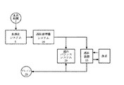
図1は、透析システムの高水準概略図である。透析システムは、複数のサブシステムを有し、これらサブシステムは、水を受取って浄化し、当該浄水を用いて透析液を準備し、当該透析液を、様々な種類の透析(例えば、血液透析、限外濾過及び血液透析濾過)を患者の血液に対して行う透析装置に供給するため、集合的に動作する。透析システムは、水、透析液及び血液が透析システムを流通するための流体流路を提供する配管、並びに、流体がシステム全体に流れ渡るよう配管とインタフェース接続された1つ又は複数のポンプを有する。透析システムはさらに、例えば、流体流れセンサ、圧力センサ及び伝導率センサ等の、システムを流通する流体に関する1つ又は複数の特徴を検知及び報告する1つ又は複数のセンサを有することができる。 FIG. 1 is a high level schematic diagram of a dialysis system. The dialysis system has a plurality of subsystems that receive and purify water, prepare dialysate using the purified water, and use the dialysate for various types of dialysis (eg, hemodialysis). Collective operation to supply a dialysis machine that performs ultrafiltration and hemodiafiltration on the patient's blood. The dialysis system has piping that provides a fluid flow path for water, dialysate, and blood to flow through the dialysis system, and one or more pumps interfaced with the piping so that fluid flows throughout the system. . The dialysis system can further include one or more sensors that detect and report one or more characteristics relating to fluid flowing through the system, such as, for example, fluid flow sensors, pressure sensors, and conductivity sensors.
一実施形態において、(水準備・水浄化システム、透析液準備システム、流れバランスシステム、透析装置並びに配管及びセンサといったハードウェアを含む)透析システム全体は、小型かつ軽便な単一のハウジングに収容されている。さらに、透析システムは、例えば、家庭又はホテルの一室の水道水を用いて透析液を準備することができる。一実施形態において、透析システム全体は、乾燥時において、約22×14×9インチ未満のスペースをとるが、これは一般的に言って、機内持ち込み荷物のサイズ制限に相当するスペースである。一実施形態において、透析システム全体の重量は、乾燥時において、約50ポンド未満である。 In one embodiment, the entire dialysis system (including hardware such as water preparation and purification system, dialysate preparation system, flow balance system, dialysis device and piping and sensors) is housed in a single housing that is small and convenient. ing. Furthermore, the dialysis system can prepare dialysate using, for example, tap water from a room in a home or hotel. In one embodiment, the entire dialysis system takes up less than about 22 x 14 x 9 inches of space when dry, which is generally a space that corresponds to the size limit of carry-on luggage. In one embodiment, the overall weight of the dialysis system is less than about 50 pounds when dry.
図1を参照すると、透析システムは、水供給源7からの水を浄化する水準備・水浄化システム5を有する。水浄化システム5は、浄水を透析液準備システム10に供給し、透析液準備システム10は、当該浄水を用いて透析液を準備する。透析システムはさらに透析装置15を有する。透析装置15は、透析液を透析液準備システム10から受取り、患者の血液に対して透析を行う。一実施形態において、透析装置15及び透析液準備システム10はいずれも、流れバランスシステム20とインタフェース接続されている。流れバランスシステム20は、詳細に後述するように、例えば血液透析、限外濾過及び血液透析濾過といった様々な種類の透析を実現するために、透析装置への透析液の流れを調節する。
Referring to FIG. 1, the dialysis system includes a water preparation / water purification system 5 that purifies water from a water supply source 7. The water purification system 5 supplies purified water to the
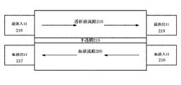
拡散は、血液透析が、血液から老廃物(中でも、尿素、クレアチニン、リン酸塩及び尿酸等)を除去する主要なメカニズムである。透析液の化学組成と透析装置内の血液の化学組成との差により、老廃物は、血液から膜を通って透析液に拡散する。限外濾過とは、流体が血液から膜を通して透析液に移動される透析の一方法であって、一般的に患者の血液流からの余剰流体の除去を目的としている。水と共に、何らかの溶液も、拡散というよりむしろ対流により膜を通して取出される。限外濾過は、透析装置における血液室と透析液室との間の圧力差により生じ、流体は、圧力が高い方から低い方へと移動する。場合によっては、設計又は意図しない成行きにより、透析液室の流体が血液室より高くなり、流体が透析液室から血液室に移動される。これは一般的に逆限外濾過と呼称される。 Diffusion is the primary mechanism by which hemodialysis removes waste products from the blood, such as urea, creatinine, phosphate and uric acid. Due to the difference between the chemical composition of the dialysate and the chemical composition of the blood in the dialyzer, the waste products diffuse from the blood through the membrane into the dialysate. Ultrafiltration is a method of dialysis in which fluid is transferred from the blood through the membrane to the dialysate and is generally aimed at removing excess fluid from the patient's blood stream. Along with water, some solution is also removed through the membrane by convection rather than by diffusion. Ultrafiltration occurs due to the pressure difference between the blood chamber and the dialysate chamber in the dialyzer, and the fluid moves from the higher pressure to the lower pressure. In some cases, due to design or unintended consequences, the fluid in the dialysate chamber is higher than the blood chamber and fluid is moved from the dialysate chamber to the blood chamber. This is commonly referred to as reverse ultrafiltration.
血液透析濾過においては、膜を通じた対流による溶液輸送を増加させることを目的として、患者の血液から除去が必要な量より多い高レベルの限外濾過が生じる。そこで、患者の血液から除去が必要な量を上回る分の流体は、逆の血行力学的反応を回避するため、血液流に戻される。これは、透析装置の透析液室における圧力を意図的に上昇させて、適量の逆限外濾過を生じさせることにより実現される。限外濾過と逆限外濾過とを交互に行う上記の方法は、しばしば「プッシュプル血液透析濾過」と呼称される。これは、透析装置の外部の場所において無菌流体が患者に投与される、より一般的な血液透析濾過の方法に比べて、著しい向上である。 In hemodiafiltration, high levels of ultrafiltration occur that exceed the amount that needs to be removed from the patient's blood, with the goal of increasing convective solution transport through the membrane. Thus, the excess of fluid that needs to be removed from the patient's blood is returned to the blood stream to avoid the reverse hemodynamic response. This is achieved by deliberately increasing the pressure in the dialysate chamber of the dialyzer to produce the appropriate amount of reverse ultrafiltration. The above method of alternating ultrafiltration and reverse ultrafiltration is often referred to as “push-pull hemodiafiltration”. This is a significant improvement over the more common hemodiafiltration methods where sterile fluid is administered to the patient at a location external to the dialyzer.
使用に際し、患者は、当業者に周知の装置及び技術を用いて透析装置15に繋げられ、患者の血液が透析装置15の内外へ流れる。透析システムは、家庭用水源(例えば、蛇口)からの水を用いて透析液を準備する。こうした水は予め、濾過及び浄化により準備され、その後様々な透析液成分と混合されて透析液を生成するものである。透析システムはそれから、血液に対して1つ又は複数の透析処理が行われるよう、透析液を、血液に連通された透析装置に流通させる。水浄化システムは、複数のサブシステムを有し、これらサブシステムは、さらに詳細に後述するように、水の殺菌等の浄水処理のために集合的に動作する。浄水はそれから、透析液原液と混合されて透析液を生成し、生成された透析液は、透析装置15及び流れバランスシステムに供給される。流れバランスシステムは、さらに詳細に後述するように、例えば血液透析、限外濾過及び血液透析濾過といった様々な種類の透析を実現するために、透析液の透析装置15への流れを調節する。透析システムは、使用済みの透析液をドレイン25へ送る。一実施形態において、システムは、使用済みの透析液がドレインに流れる前に、その透析液から熱を回収する。
In use, the patient is connected to the
I.[透析システムの例示的なサブシステム] I. [Example Subsystem of Dialysis System]
ここから、透析システムの様々な(水浄化システム5、透析液準備システム10、透析装置15及び流れバランスシステム20を含む)サブシステムに関する例示的実施形態について説明する。そうした説明は例示的であって、変形が可能であることを理解されたい。
From now on, exemplary embodiments relating to various subsystems of the dialysis system (including the water purification system 5, the
1.[水浄化システム] 1. [Water purification system]
図2は、水浄化システム5の高水準概略図である。水浄化システム5は、複数のサブシステム及び/又は図2に概略的に示されたそれぞれの部品を有する。水浄化システム5は、浄水の文脈で説明されるが、水以外の流体を浄化するためにも用いられ得る。水は、(図1の水供給源7から)流体浄化システムにエントリ位置105において入り、流路に沿って透析液準備システム10の方へ流れる際に、各サブシステム及び各部品と連通する。サブシステムは、例えば、沈殿物濾過システム115、炭素濾過システム120、逆浸透システム125、限外濾過システム130、補助ヒータシステム135、脱ガスシステム140又はこれらのいかなる組み合わせを有することができる。
FIG. 2 is a high-level schematic diagram of the water purification system 5. The water purification system 5 has a plurality of subsystems and / or respective components schematically shown in FIG. The water purification system 5 is described in the context of water purification, but can also be used to purify fluids other than water. As the water enters the fluid purification system (from the water source 7 of FIG. 1) at
流体浄化システム5を出て、透析液準備システム10に入る前に、流体は浄化された状態となる。これは、好適には、流体が殺菌された状態を含む。ただし、流体システムは必ずしも全ての場合において流体を殺菌するわけではない。図2に示された実施形態は例示的であって、図2に示された部品全てが必ずしも水浄化システム5に含まれるわけではない。システムに含まれる各部品は、必要となる浄化又は殺菌の種類及びレベルに応じて変更され得る。図2に示された流路に沿ったサブシステムの数及び順序は、例示を目的としており、当然のことながら、変更することができる。
Before leaving the fluid purification system 5 and entering the
ここから、流体浄化システム5を用いた例示的な浄水方法について、システム内の流体の流路の説明を含めて説明する。上述したように、水は、水浄化システム5にエントリ位置105から入る。エントリ位置は、流入水が少なくとも2つの水源から供給されように設定された三方弁を有することができる。そうした水源の1つは、家庭用の給水蛇口とすることができる。代替的に、弁は、予め水浄化システム5を通され、システムに再び送り込まれて、例えば、システムを洗流する再循環水を受取るように設定され得る。弁が、再循環水を受取るように設定されている場合は、再循環弁水は、水浄化システム5を流通する際に、1つ又は複数のサブシステムを迂回することとしてもよい。
From here, the example water purification method using the fluid purification system 5 is demonstrated including description of the flow path of the fluid in a system. As described above, water enters the water purification system 5 from the
弁が家庭用の給水蛇口から水を受取るよう設定されている場合は、流入水はまず、少なくとも1つの沈殿物濾過システム115を流れる。沈殿物濾過システム115は、通過させた水から沈殿物を濾過する1つ又は複数の沈殿物フィルタを有する。一実施形態において、沈殿物濾過システム115は、5ミクロンまでの粒子状物質又はさらには1ミクロンまでの粒子状物質を除去する。沈殿物フィルタの上流又は下流には、流れの状況をモニタするために、圧力センサが配置され得る。また、流路は、流体圧力を調節して、システム内で所望の流速を実現するよう構成された、1つ又は複数の圧力調節装置を有することができる。圧力調節装置は、所望範囲を上回る又は下回る流速を有する家庭用蛇口を調整するために用いられ得る。
If the valve is set to receive water from a domestic water tap, the incoming water will first flow through at least one
水はそれから、炭素濾過システム120を流通する。炭素濾過システム120は、水から、例えば、有機化学品、塩素及びクロラミンといった物質を濾過する1つ又は複数の炭素濾過フィルタを有する。一実施形態において、炭素濾過システム120は、2つの炭素フィルタを有し、当該炭素フィルタ間の流路にはサンプルポートが配置されている。サンプルポートは、例えば品質制御を目的として、オペレータがシステムを流通する水にアクセスすることを可能にする。一実施形態において、炭素濾過システム120の下流の流路には、少なくとも1つの圧力センサ及び少なくとも1つの伝導率センサが配置されている。伝導率センサは、水から除去された溶解物質のパーセンテージに関する表示を行う。また、1つ又は複数のポンプが、水の流路に沿って様々な位置(例えば、濾過サブシステムの間)に配置され得る。
The water then flows through the
水は、炭素濾過システム120から、逆浸透の手法に従って水から粒子を除去するよう構成された逆浸透システム125の方へ流れる。逆浸透システム125は通常、溶解物質の総量の95%を上回る量を水から除去する。逆浸透システム125は、廃水出口126及び純水出口127を含む2つの出口を有する。廃水出口126は、逆浸透システム125から廃水を出す。廃水は、水流路の上流位置に戻るようルートを変更され、逆浸透システム125に再び入り得る。その際、逆浸透システム125の上流には、水の含有物を確認するための手段として、センサ(例えば、伝導率センサ)が配置され得る。代替的に、廃水出口126は、廃水をドレインに供給してもよい。
Water flows from the
沈殿物濾過システム115、炭素濾過システム120及び逆浸透システム125は集合的に、溶解物質、細菌汚染及び化学汚染が生じた場合に、それらの殆どを水から除去する前処理工程を構成する。すなわち水は、前処理工程を終えた時点で、いくらかマクロ洗浄された状態となる。したがって、前処理工程は、比較的清潔な水を下流のポンプ、さらには水を殺菌する下流の熱交換システム110に供給する。前処理工程は、熱交換システム110による水の加熱時におけるスケールの付着及び腐食の可能性を低減又は排除する。
Collectively, the
熱交換システム110の流路の上流及び/又は下流には、同伴ガスを水から除去するための1つ又は複数の脱ガスシステム140が配置され得る。脱ガスシステム140は、同伴ガスを水から除去するよう構成された任意の様々な部品を有することができる。例えば、脱ガスシステム140は、スプレーチャンバ及び/又は気泡トラップを有することとしてもよい。
One or
水が前処理工程を過ぎると、水はポンプ150に流れ、ポンプ150は、水を熱交換(HEX)システム110に送る。熱交換システム110は、水の殺菌が実現される温度まで水を加熱する。一実施形態において、熱交換システム110は、マイクロ流体熱交換システムである。以下、マイクロ流体熱交換システムの例示的実施形態について、詳細に説明する。熱交換システム110は、当該システム110を流れる水の熱ロスの可能性を低減するために、断熱材に包まれ得る。
When the water passes the pretreatment process, the water flows to the
ポンプ150は、水圧を、熱交換システム110で直面する飽和圧力より高いレベルまで上昇させるために用いられ得る。これにより、熱交換システム110内の水の相変化が回避される。したがって、熱交換システム110における最高温度が摂氏150度であり、水が当業者には周知の飽和圧力を有する場合を想定すると、この場合、ポンプから出る水の圧力を、ある安全域分(例えば、10psi)だけ上記飽和圧力より高くして、確実に相変化が生じないようにすることができる。好適には、ポンプは、水圧を飽和圧力以上のレベルまで上昇させて、確実に局所沸騰が生じないようにする。このことは、熱交換システムが水の殺菌のため用いられ、水が摂氏138度を上回る高温(すなわち、大気圧における水の沸点よりはるかに高い温度)に晒される場合に重要である。
The
水は、熱交換システム110を出ると、ポンプ150から熱交換システム110の出口までの水路全体の圧力を維持する絞り弁160(例えば、流れ制限装置)に移動する。絞り弁160及びポンプ150を制御及び調節して、流速及び所望の圧力形態を実現することができる。ポンプ150及び絞り弁160は、閉ループ制御システムにおいて連通しており、それにより、確実に、所望の流速及び温度のために必要な圧力が維持される。また、1つ又は複数の温度センサ及び/又は流量センサが熱交換システムの流路の下流に沿って配置され、ポンプ150及び絞り弁160の制御のため用いられ得る。
As the water exits the
水は、絞り弁160を出ると、限外濾過(UF)システム130に移動する。限外濾過(UF)システム130は、高分子、及び殺菌工程により駆除された全て又は略全ての死細菌を水から除去して、それにより、確実に、透析液を混合される前の水に残留エンドトキシンがない状態とする。高分子の存在は、透析工程にとって不利であると考えられる。水はそれから、ヒータシステム135を通過する。ヒータシステム135は、必要又は希望があれば、水を所望の温度(例えば、通常の体温である華氏98.6度)まで加熱する。ヒータシステム135から、水は透析液準備システム10に移動する。
As the water exits the
一実施形態において、ヒータシステム135の流路の上流には、第二熱交換システムが配置される。第二熱交換システムは、熱交換システム110から排出された水が所定の所望温度(例えば、摂氏37度)を上回った場合に、水をさらに冷却するために用いられる。第二熱交換システムは、冷却媒体として作用する別個の冷却水源に接続されるか、又は、逆浸透システム125から排出された水に接続され得る。第二熱交換システムは、水源が極めて高温の水を給水する環境及び/又は熱交換システム110が透析に使用できる程十分に水を冷却することができない場合に用いられ得る。
In one embodiment, a second heat exchange system is disposed upstream of the flow path of the
2.[マイクロ流体熱交換システム] 2. [Microfluidic heat exchange system]
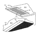
上述したように、水浄化システム5は、水を殺菌するよう構成された熱交換システム110を用い得る。図3は、例示的実施形態に係る、マイクロ流体熱交換システム110を示す概略平面図であり、マイクロ流体熱交換システム110は、当該システムを流れるある液体(例えば、水)の殺菌を、当該流体に/から熱を追加/除去するための第二流体流を必要とすること無く実現するよう構成されている。図3は、概略的であって、当然のことながら、流路の実際の実施形態(例えば、流路のサイズ及び形状)については変形が可能である。
As described above, the water purification system 5 may use the
さらに詳細に後述するように、マイクロ流体熱交換システムには、流体の流路であって、(1)少なくとも1つの流体入口と、(2)流入流体が少なくとも1つのヒータを用いて殺菌温度まで加熱されるヒータ領域と、(3)流体が所定時間の間、殺菌温度以上の状態に保たれる滞留チャンバと、(4)流入流体が、(流入流体に比べて)より高温の流出流体から熱を回収し、流出流体が、流入流体に熱を移動させることにより冷却される、熱交換セクションと、(5)流出流体が、冷却及び殺菌された状態で存在する流体出口とを有する流体の流路が規定されている。流出流体の所望温度に応じて、当該流出流体の実際の温度を、例えば、透析に用いられる所望温度に調節するために、1つ又は複数の追加的な熱交換が下流において用いられ得る。このことは、流入水が、寒冷な気候における流入水よりも何十度も高くなり、更なる冷却が施されなければ、出口においてより高い温度になり得るような温暖な気候において、特に当てはまる。 As will be described in more detail below, a microfluidic heat exchange system includes a fluid flow path comprising (1) at least one fluid inlet and (2) an inflowing fluid to a sterilization temperature using at least one heater. A heater area to be heated, (3) a dwell chamber where the fluid is kept above the sterilization temperature for a predetermined time, and (4) the incoming fluid is from a hotter outgoing fluid (compared to the incoming fluid). A heat exchange section in which heat is recovered and the effluent fluid is cooled by transferring heat to the inflow fluid, and (5) a fluid outlet having a fluid outlet where the effluent fluid exists in a cooled and sterilized state. A flow path is defined. Depending on the desired temperature of the effluent fluid, one or more additional heat exchanges can be used downstream to adjust the actual temperature of the effluent fluid to, for example, the desired temperature used for dialysis. This is especially true in warm climates where the incoming water is tens of degrees higher than the incoming water in cold climates and can be at higher temperatures at the exit if no further cooling is applied.
一実施形態において、流路は、少なくとも部分的に、1つ又は複数のマイクロチャネルから形成される。ただし、後述するようなマイクロ流体の流れ場を流体の流路のいくつかの部分(例えば、熱交換セクション)に用いることも、本発明の範囲に含まれる。マイクロチャネルの寸法を比較的小さくすれば、システムにおける向流路間の拡散路長及び材料量が減少し、熱交換システムの熱移動速度が向上する。一実施形態において、マイクロチャネルは、約1000μm未満の次元を少なくとも1つ有する。マイクロチャネルの寸法は、変更することができ、一般的には、所望の熱移動特性を実現するよう設計される。水力直径が約0.1mm〜約1mmの範囲のマイクロチャネルでは、一般的に、マイクロチャネル全体、特にマイクロチャネルの熱交換領域において、層流流体流が得られる。また、マイクロチャネルのサイズを小さくすれば、熱交換システム110はコンパクトかつ軽量になり得る。一実施形態において、マイクロチャネルは、以下に形成されるようなスタックの形に配された1つ又は複数の薄層板に形成される。
In one embodiment, the flow path is at least partially formed from one or more microchannels. However, it is also within the scope of the present invention to use a microfluidic flow field as will be described later in some parts of the fluid flow path (eg, heat exchange section). Reducing the size of the microchannels reduces the length of the diffusion path and the amount of material between the counter-flow channels in the system and improves the heat transfer rate of the heat exchange system. In one embodiment, the microchannel has at least one dimension less than about 1000 μm. The dimensions of the microchannel can be varied and are generally designed to achieve the desired heat transfer characteristics. For microchannels with a hydraulic diameter in the range of about 0.1 mm to about 1 mm, laminar fluid flow is generally obtained throughout the microchannel, particularly in the heat exchange region of the microchannel. Further, if the size of the microchannel is reduced, the
マイクロ流体熱交換システム110の流路は、向流路形態に配され得る。つまり、流路は、低温の流入流体が、高温の流出流体と熱連通状態で流れるように配されている。高温の流出流体は、低温の流入流体に熱エネルギーを移動し、それにより、流入流体を殺菌温度まで加熱するヒータを補助する。このように、流入流体を、入口における温度より高い温度まで内部で予め加熱することにより、ヒータが所望の最高温度に達するために消費するエネルギー量が低減される。また、熱エネルギーを流出流体から流入流体に移動することにより、事前に熱せられた流出流体は、流体出口から出る前に冷却される。その結果、流体は、マイクロ流体熱交換システム110に入る際は「低温」に、それから内部の流体流路を通過する際は(まず熱交換、そして次にヒータにより)加熱され、マイクロ流体熱交換システム110を出る際は再び「低温」になる。すなわち、流体は、第一温度でマイクロ流体熱交換システム110に入り、第一温度より高い第二温度まで(熱交換及びヒータにより)加熱される。流体が出口路の方へ進むと、当該(第二温度の)流体は、その温度が、第二温度よりも低く、第一温度より高い第三温度に低下するよう、流入流体に熱を移動する。
The flow path of the microfluidic
ここから、マイクロ流体熱交換システム110の流体流路及び対応する部品の例示的実施形態について、図3を参照しながらさらに詳細に説明する。図3は、片側には入口及び出口を、反対の端部側には中央熱交換部分及び加熱セクションを有する銃剣型の熱交換装置を示す。流体は、入口282を通ってマイクロ流体熱交換システム110に入る。図示された実施形態において、流体流路は、1つ又は複数の流入マイクロチャネル284と流出マイクロチャネル286とに分かれており、流入マイクロチャネル284は、流出マイクロチャネル286と向流の形で配置されている。上述したように、マイクロ流体熱交換システム110は、層状の薄層板のスタックにより形成され得る。流入マイクロチャネル284は、流出マイクロチャネル286の上又は下に交互に配される形で、流出マイクロチャネル286に対して別個の層に配置され得る。別の実施形態において、流入マイクロチャネル284及び流出マイクロチャネル286は、単一の層に配置される。
An exemplary embodiment of the fluid flow path and corresponding components of the microfluidic
流出マイクロチャネル286は、出口288に連通している。図示された実施形態において、入口282及び出口288は、マイクロ流体熱交換システム110の同じ端部側に配置されている。ただし、入口282及び出口288は、互いに異なる位置にも配置され得る。
向流配置は、流入マイクロチャネル284を流出マイクロチャネル286と熱連通させる。この場合、流入マイクロチャネル284における流体は、流出マイクロチャネル286における流体の流れの方向ベクトルに対して約180度の方向に配向された方向ベクトルに沿って流れることができる。また、流入及び流出マイクロチャネルは、流入マイクロチャネル284における流体が、流出マイクロチャネル286における流体の流れの方向ベクトルに対して約180度〜約90度の方向に配向された方向ベクトルに沿って流れ得る交差流形態であってもよい。流入マイクロチャネルの流出マイクロチャネルに対する方向は、流入及び流出マイクロチャネル間の所望の熱連通の度合いを実現するよう構成されたあらゆる方法において変更することができる。
The countercurrent arrangement places the
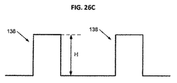
1つ又は複数のヒータ292が、当該ヒータ292がシステムにおいて流れる流体に熱を加え得るよう、少なくとも流入マイクロチャネル284と熱連通状態で配置される。ヒータ292は、流体がヒータ292のいくつかの側面を取り囲む形で流れるよう、流入マイクロチャネル284の内部に配置され得る。あるいは、ヒータ292は、流体がヒータ292の一側面に沿って流れるよう、流入マイクロチャネル284の側面に配置され得る。いずれの場合も、ヒータ292は、流体温度が所望の温度(これは、水が浄化される場合は、殺菌温度を含んでいてもよい)に達するのに十分な熱を流体に伝達する。一実施形態において、流体は水であり、ヒータ292は、流体を標準大気圧において摂氏100度以上の温度まで加熱するのを補助する。一実施形態において、流体は水であり、ヒータ292は、流体を標準大気圧において摂氏120度以上の温度まで加熱するのを補助する。一実施形態において、流体は水であり、ヒータ292は、流体を標準大気圧において摂氏130度以上の温度まで加熱するのを補助する。一実施形態において、流体は水であり、ヒータ292は、流体を標準大気圧において摂氏138度以上の温度まで加熱するのを補助する。別の実施形態において、流体は水であり、摂氏約138度〜摂氏約150度の範囲の温度まで加熱される。別の実施形態において、流体は、蒸発を生じない最高の温度まで加熱される。
One or
したがって、マイクロ流体熱交換システム110は、流体を単相液体として維持することができる。一般的に、水は、摂氏約100度で液体状態から気体状態に相を変化させるため、上述した温度まで水を加熱するには、単相液体が終始維持されるよう、熱交換システムを加圧する必要がある。流体を液体状態のまま維持するには、熱交換システムにおける最高温度に相当する飽和温度を上回る圧力があれば十分である。安全域として、圧力は一般的に、飽和圧力より高い10psi以上に保たれる。一実施形態において、マイクロ流体熱交換システムにおける水圧は、水の沸騰を回避するために、485kPaより高い状態で維持され、確実に沸騰が生じないようにするために、そのレベルを著しく上回る、例えば、620kPa又は900kPaの高い状態で維持され得る。そうした圧力は、熱交換システムにおいて、ポンプ及び絞り弁を用いて維持される。熱交換システム上流のポンプ及び熱交換システム下流の絞り弁は、ポンプ及び絞り弁が(例えば、センサを有する)閉ループ制御セットアップで動作している場合に、所望の圧力及び流速を熱交換システム全体において維持するために用いられる。
Thus, the microfluidic
流体が殺菌温度まで加熱されると、流体は、滞留チャンバ294に移動する。滞留チャンバ294において、流体は殺菌温度以上まで加熱された状態のまま一定時間保たれる。この時間は、「滞留時間」又は時に「ドウェル時間」と呼称される。一実施形態において、ドウェル時間は、流体の流路長及び流速に応じて、1秒以下、1秒〜2秒の間又は2秒以上とすることができる。温度が高いほど、細菌駆除の面で効率的であり、滞留時間が短いほど、コンパクトな装置を意味する。
As the fluid is heated to the sterilization temperature, the fluid moves to the
細菌の全てのコロニー数(コロニー形成単位:CFU)を10−6CFU/ml未満の濃度まで駆除する(例えば、不溶解性透析液と共に用いる水を浄化するための)超高温殺菌法は、水を摂氏138度〜摂氏150度まで加熱して、約2秒以上のドウェル時間設けて実行されることが規定されている。超純化透析液は、0.1CFU/ml以下の細菌量を含む。表1は、様々なレベルの殺菌を実現するために必要な温度及び滞留時間を示す。本明細書に記載の熱交換システムは、表1に示される様々なレベルの殺菌を実現するよう構成されている。

流体はそれから、滞留チャンバ294から流出マイクロチャネル286に流れ、そこから、流体出口288の方へ流れる。上述したように、流出マイクロチャネル286は、流入マイクロチャネル284と向流の関係、かつ流入マイクロチャネル284と熱連通された状態で配置されている。このように、(流出マイクロチャネル286を流れる)流出流体は、(流入マイクロチャネル284を流れる)流入流体と熱連通している。加熱された流体が流出マイクロチャネル286を流れると、加熱された流体からの熱エネルギーが、隣接する流入マイクロチャネル284を流れる、より低温の流体に移動される。熱エネルギー交換により、流体が滞留チャンバから流出マイクロチャネル286を流れると、当該流体は冷却される。さらに、流入流体は、ヒータ292に達する前に流入マイクロチャネル284を流れる際に、熱交換により予め加熱される。一実施形態において、流出マイクロチャネル284における流体は、流体への細菌の侵入を防ぐことができる最低温度以上の温度まで冷却される。熱交換システムにより流体が殺菌される場合は、流体が熱交換システムを出る際に、流体の細菌は、所望の浄化レベルまで殺菌されている。こうした場合、熱交換システムを出た後の流体の温度は、流体が透析に使用されるまで、室温の状態で維持され得る。別の実施形態において、熱交換システムを出る流体は、正常体温以下の温度まで冷却される。
The fluid then flows from the
図3には、流入チャネル間に挟まれた出口を有する一実施形態が示されているが、所望の加熱及び冷却の度合い並びに所望のヒータのエネルギー所要量を実現するための他のチャネル配置も可能である。ただし、あらゆる実施形態に共通することとして、システム内の全ての流体流路は、1つの流体が、当該1つの流体に/から熱を追加/除去するための第二の流体を必要とすること無く流れるよう設計されている。すなわち、前記1つの流体は、流体流路の諸位置において、当該流体自体に依存した形で加熱及び冷却される。 FIG. 3 shows an embodiment having an outlet sandwiched between the inflow channels, but other channel arrangements to achieve the desired degree of heating and cooling and the desired heater energy requirements are also possible. Is possible. However, as is common to all embodiments, all fluid flow paths in the system require one fluid to require a second fluid to add / remove heat to / from the one fluid. Designed to flow without any problems. That is, the one fluid is heated and cooled at various positions of the fluid flow path in a manner depending on the fluid itself.
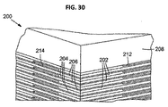
マイクロ流体熱交換システム110の寸法は、変更することができる。一実施形態において、マイクロ流体熱交換システム110は、ユーザの手に入る程十分に小さい。別の実施形態において、マイクロ流体熱交換システム110は、乾燥時に5ポンド未満の重量を有する単一本体である。別の実施形態において、全システム110のマイクロ流体熱交換部分350は、約1立方インチの体積を有する。マイクロ流体熱交換システム110の寸法は、所望の温度及びドウェル時間特性が実現されるよう選択することができる。
The dimensions of the microfluidic
上述したように、マイクロ流体熱交換システム110の一実施形態は、複数の薄層板ユニットが上下に積層され、薄層板層を形成して構成される。薄層板が上下に積層されると、これら薄層板間にマイクロ流体チャネル又は流れ場が形成されるよう、各薄層板には、所望のマイクロ流体の流路がエッチングされ得る。なお、ブラインドエッチング及び貫通エッチングの両方を、薄層板にチャネルを形成するため用いることができる。具体的に言えば、貫通エッチングは、流体が、薄層板面を変更して他の薄層板スタックの層に移動することを可能にする。このことは、一実施形態においては、後述するような、流体がヒータセクションに入る流入薄層板の出口において生じる。貫通エッチングにより、入口薄層板の面のみにおいて流体が保持されず、ヒータセクションの周辺の全ての薄層板が流体の加熱に関与することが可能となる。上記実施形態は、表面積を増加させると共に流速を全体的に低くして、流体の必要温度までの加熱を容易にし、ひいては装置の効率に寄与する。
As described above, one embodiment of the microfluidic
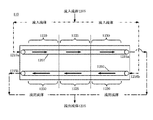
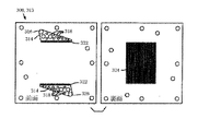
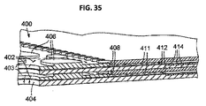
薄層板のブラインドエッチング及び/又は貫通エッチングにより生じたマイクロチャネル又は流れ場は、流体の流路を形成する。図4Aは、例示的実施形態に係る、流体が熱交換システム110を内方向(矢印307により示される方向)に流れる少なくとも1つの入口流路を形成する入口薄層板305を示す平面図である。図4Bは、例示的実施形態に係る、流体が熱交換システム110を外方向(矢印312により示される方向)に流れる少なくとも1つの出口流路を形成する出口薄層板310を示す平面図である。入口流路及び出口流路はそれぞれ、1つ又は複数のマイクロチャネルを有することができる。一実施形態において、入口流路及び出口流路は、平行の関係に配置された複数のマイクロチャネルを有する。
Microchannels or flow fields generated by blind etching and / or through-etching of thin layer plates form fluid flow paths. FIG. 4A is a plan view illustrating an
組立てられた装置においては、薄層板は、入口流路及び出口流路を見せつつ交互に上下に重ね合わされた形で積層されるが、図4A及び図4Bは、薄層板305、310を隣接配置の形で示す。入口薄層板305及び出口薄層板310は、流体が流体導管を通って入口流路から出口流路に流れ得るよう、流体導管を挟んで上下に積層される。積層時に、移動層が入口薄層板305と出口薄層板310との間に挿入され得る。移動層は、出口流路中の流体から入口流路中の流体に熱が移動され得るよう構成されている。移動層は、熱を、ある流体から別の流体へ所望の用途に適した十分な速度で移動させることが可能な任意の材料とすることができる。関連性のある要素として、下記に限定されないが、熱移動層110の熱移動性、熱移動層の厚み及び熱移動の所望速度が含まれる。適切な材料として、下記に限定されないが、金属、合金、セラミック、ポリマー又はこれらの合成物が含まれる。適切な材料として、下記に限定されないが、ステンレススチール、鉄、銅、アルミニウム、ニッケル、チタン、金、銀、錫及びこれら金属の合金が含まれる。銅は、特に好ましい材料であると言える。別の実施形態において、入口薄層板と出口薄層板との間には移動層がなく、薄層板自体が流路間の熱移動層としての役割を果たす。
In the assembled apparatus, the thin plate is laminated in the form of being stacked one above the other while showing the inlet flow channel and the outlet flow channel, but in FIGS. 4A and 4B, the
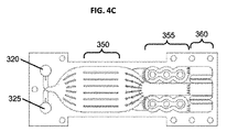
入口薄層板305及び出口薄層板310はいずれも、少なくとも1つの入口開口部320及び少なくとも1つの出口開口部325を有する。入口薄層板305及び出口薄層板310が上下に積層され、正確に位置決めされると、図4Cに示されるように、入口開口部320は一直線に並び、集合的に、スタック全体に延びて入口薄層板305の入口流路に連通する流体流路を形成する。同様に、出口開口部325も一直線に並び、集合的に、出口薄層板310の出口流路に連通する流体流路を形成する。熱交換システム110の入口流路及び出口流路の複数層を形成するため、任意の数の入口薄層板及び出口薄層板を積層することができる。層の数は、マイクロ流体熱交換システム110の所定の特徴(例えば、流体における熱交換量及びシステムにより処理可能な流体の流速を変化させること)が実現されるよう選択することができる。一実施形態において、熱交換システム110は、100ml/min以上の流入液体の流速を実現する。
Both the
別の実施形態において、熱交換システム110は、1000ml/min以上の流入液体の流速を実現する。こうした熱交換システムは、マイクロ流体の流路がマスキング/化学エッチング処理を用いて形成された複数の薄層板から作成され得る。薄層板はそれから、さらに詳しく後述するように、スタックの形で拡散接着される。一実施形態において、スタックは、40〜50の薄層板を有し、各薄層板で2〜3ml/minの流速が得られる。熱交換装置内の積層された薄層板のペア数を増やすことで、より大きな流速を得ることができる。他の実施形態において、はるかに高い流速がシステムで処理され得る。
In another embodiment, the
作動時において、流体は、入口開口部320を通って入口薄層板305の入口流路に流入する。このことは、入口薄層板305の入口領域の拡大図である図5を参照しながら、さらに詳細に説明する。入口開口部320は、流体を入口流路に誘導する入口導管405に連通している。入口開口部320は、入口導管405のサイズに対して所定のサイズとなるよう構成することができ、例えば2mmの直径を有することとしてもよい。また、例えば一実施形態において、入口開口部320は、入口導管405の水力直径に対応して、それより約10倍〜15倍大きな水力直径を有することとしてもよい。水力直径の上記の比率は、流体を複数の入口薄層板に比較的均等に分配させることが分かっている。別の実施形態において、2mmの広径入口流路の場合、スタック全体の流体の均等な分配を確実にするために、10:1より大きな水力直径比率(例えば、15:1)が用いられ得る。
In operation, fluid flows into the inlet flow path of the
図5をさらに参照すると、入口導管405の下流端部は、入口流路に開いており、入口流路のサイズは、入口導管405のサイズに比べて外方向に拡がっている。この点において、1つ又は複数の流れ剥離ガイド(例えば、フィン410)が入口流路への経路に配置され得る。流れ剥離フィンのサイズ及び形状は、流体が入口導管405から入口流路に流入する際に、均等に分配され易くなるよう作られている。当然のことながら、入口導管405及び入口流路のサイズ、形状及び輪郭は、変更することができ、図5に示された実施形態は単に例示にすぎない。また、一例にすぎないが、システムの上記領域は、(後述される)ピン形状の部材の流れ場を有し、これら部材の周辺を流体が流れることとしてもよい。
With further reference to FIG. 5, the downstream end of the
図4Aを再び参照すると、入口流路及び出口流路はそれぞれ、熱交換領域を有する。熱交換領域は、集合的には参照符号350を用いて呼称され、個別には参照符号350a(入口流路の場合)及び参照符号350b(出口流路の場合)を用いて呼称される。熱交換領域350は、入口流路の(出口流路における流体に対して)低温の流体が、出口流路の(入口流路における流体に対して)高温の流体から熱を受取るところである。上述したように、入口流路における比較的低温の流体は、出口流路における比較的温かい流体と連通状態で流れるよう配置される。この層の実施形態において、流入流路は、薄層板積層の際に、流出流路の真上(又は真下)に配置される。流入流路における流体と流出流路における流体の温度差及び当該2つの流路を隔てる材料の熱移動性により、熱は、流出流路における流体から、移動層を通って、流入流路における流体に移動する。ここでも、熱交換領域は、上述したように一連のマイクロチャネルを有する替わりにマイクロ流体流れ場を有することができる。
Referring back to FIG. 4A, the inlet and outlet channels each have a heat exchange region. The heat exchange regions are collectively referred to with
図4Aをさらに参照すると、流入流路における流体は、熱交換領域350からヒータ領域355に流入する。複数のピン357が、熱交換領域350とヒータ領域355との間の入口流路に配置され得る。ピン357は、流体の流れを中断させて混合を促進し、それにより、流体の流れ具合及び熱分布の両方の向上を図ることができる。図6は、ヒータ領域355の拡大図である。一実施形態において、流入流路は、ヒータ領域355において所望の流速に合わせて少なくとも2つの流路に分岐する。代替的には、ヒータ領域全体で、1つのみの流路を用いるか、又は、3つ以上の流路を選択することも可能である。ヒータ領域355は、当該領域を流れる流体と連通する1つ又は複数のヒータ292を有するが、流路からは気密状態で隔離されている。ヒータ292は、流入流体の温度を所望の温度(これは、殺菌温度を含んでいてもよい)まで上昇させるのに十分な熱を当該流体に加える。流入流体は、熱交換領域350を流れる際に予め加熱されたものである。このことは、効果的には、ヒータのエネルギー所要量を低減する。
Still referring to FIG. 4A, the fluid in the inflow channel flows from the
ヒータ領域に入る流体が、スタック内の全ての薄層板を通過できるよう、スタック内の薄層板は、ヒータ領域355へのエントリ位置505において貫通エッチを有することができる。貫通エッチングにより、入口薄層板の面のみにおいて流体が保持されず、ヒータセクションの周辺の全ての薄層板が流体の加熱に関与することが可能となる。このことは、流体とヒータとの間の表面積を増加させると共に、流速を全体的に低くして、流体の必要温度までの加熱を容易にする。
The lamina in the stack can have a through etch at
上述したように、流入流路は、複数の流路に分岐させることができる。各流路は1つ又は複数のヒータ292を有することとし、ヒータ292は、当該ヒータ292と流路を流れる流体との接触表面積の大きさが最大化又はさもなければ増加されるよう、流路に配置することができる。その際、ヒータ292は、流体が常に、ヒータ292の両側を、当該ヒータ292を取り囲む形で延びる半円状又はさもなければ曲線状の流路に沿って流れるよう、流路の中央寄りに配置され得る。ヒータ292の形状は変更することができる。一実施形態において、ヒータ292は、直径が1/8インチで、一実施形態において全体的な速度が約70,000W/m2〜110,000W/m2で運転され得る従来型のカートリッジ式ヒータであり、その結果、100ml/minで動作するスタック全体で、一実施形態においては100W未満、別の実施形態においては200W未満のエネルギー消費量とすることができる。一実施形態において、システムは、各流路に3つのヒータを有する形態において、6つのヒータを用いる。この場合、各ヒータは、流速が100ml/minの場合に約70Wを使用する。一実施形態において、流体は、幅1.6mmの流路において、必ずヒータの周囲を流れる。
As described above, the inflow channel can be branched into a plurality of channels. Each flow path has one or
図4Aを再び参照すると、流入流路は、ヒータセクション355から滞留チャンバ360へと遷移する。流体は、熱交換領域350における熱移動及び/又はヒータセクション355における加熱により、滞留チャンバ360に流入する際には、所望の温度(例えば、殺菌温度)まで加熱されている。複数の薄層板が積層される場合は、各入口薄層板からの流体が、滞留チャンバ360において、1つの流体となって流入するよう、滞留チャンバ360は、スタックの全ての薄層板層に拡がる単一チャンバとすることができる。滞留チャンバ360は、流体の流れの「ショートカット」が回避され、流体のいずれの部分も、特定の流速で必要な時間よりより短い間、滞留チャンバに滞留することがなく、流体の全てが必ず流路を通り、流体が、滞留チャンバ内にある時間(すなわち、ドウェル時間)、殺菌温度以上の状態で維持されるよう構成されている。実際は、滞留時間は、滞留領域を通る流路の寸法及び流速の結果である。したがって、所望の時間のために滞留流路をどう設計するかは、当業者には明らかである。
Referring back to FIG. 4A, the inflow channel transitions from the
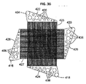
図7は、入口薄層板305及び出口薄層板310の滞留チャンバ360の領域を示す拡大図である。図示の明瞭化のため、図7は、入口薄層板305及び出口薄層板310を隣接配置の形で示している。ただし、使用時においては、薄層板は、滞留チャンバが一直線に並び、スタックに沿って上方向に拡がる滞留チャンバを形成するよう、上下に積層される。一実施形態において、滞留チャンバ360には、図7の滞留チャンバの拡大図において示されるような蛇行流路が組み込まれている。蛇行流路は、長い流路を提供し、それにより、液体滞が滞留チャンバ360内で十分な時間留まる可能性が高くなる。
FIG. 7 is an enlarged view showing the region of the
流体は、蛇行流路の終点まで達すると、(図7の矢印610により示される)出口薄層板310の出口流路に移動する。図4Bを参照すると、出口流路は、ヒータ292の間を通っており、ヒータ292は、流体が流路のこの段階において熱を失う可能性を低くするための流体の断熱材の役割を果たす。出口流路の加熱流体はそれから、熱交換領域350bの方へ流れる。出口流路は、熱交換領域350bに達するまで延びている。流体は、一連の拡張ファン367により、出口流路の拡張熱交換集合領域350bに方向付けられ、ここで、入口流路における低温の流体と熱連通する。上述したように、高温の出口流路における流体からの熱は、入口流路における低温の流体へと移動される。その結果、流出流体は冷却され、流入流体は加熱される。流体はそれから、熱交換領域350bから出口開口部325の方へ流れる。この段階で、流体は、冷却及び殺菌された状態となっている。
When the fluid reaches the end of the serpentine flow path, it moves to the exit flow path of the outlet lamina 310 (indicated by arrow 610 in FIG. 7). Referring to FIG. 4B, the outlet channel passes between the
一実施形態において、350ミクロンの厚みを有し、エッチ深さが175ミクロンであって、327ミクロンの水力直径を有する幅2.5mmのチャネルを備えた薄層板が用いられた。薄層板の各ペアは、約3.3ml/minの流体流速を処理することが可能で、この場合、全長15mmの熱交換セクションで、100ml/minの流れを促進するためには、30ペアの薄層板が必要であった。一実施形態において、流体流路は、滑らかに湾曲した曲線の形で、スタックの長手方向に沿って対称となるよう設計されている。流路が対称的に設計されていない場合は、流路のライン又は長さの差が最小限に抑えられ、流れ、流体の熱及び様々なドウェル時間が均等に分布されるよう設計されている。 In one embodiment, a thin plate with a 2.5 mm wide channel having a thickness of 350 microns, an etch depth of 175 microns, and a hydraulic diameter of 327 microns was used. Each pair of lamina can handle a fluid flow rate of about 3.3 ml / min, in this case 30 pairs to promote 100 ml / min flow in a heat exchange section with a total length of 15 mm. A thin layer plate was required. In one embodiment, the fluid flow path is designed to be symmetrical along the length of the stack in the form of a smoothly curved curve. If the flow path is not designed symmetrically, it is designed to minimize differences in flow path lines or lengths and evenly distribute flow, fluid heat and various dwell times .
熱交換部分において、チャネルを隔離するリブの幅は縮小されることができ、それにより、利用可能な熱交換領域が増加され、装置の、所望の熱効率レベルを得るために必要な熱交換部分の長さが縮小される、という効果が得られる。85%以上、又はいくつかの実施形態においては90%以上のエネルギー効率レベルが得られ、これは、流出流体からの熱エネルギーの90%が、流入流体に移動され、ロス無しに回収され得ることを意味する。 In the heat exchanging part, the width of the rib separating the channels can be reduced, thereby increasing the available heat exchanging area and of the heat exchanging part necessary to obtain the desired thermal efficiency level of the device. The effect that the length is reduced is obtained. An energy efficiency level of 85% or higher, or in some embodiments 90% or higher, is obtained, which means that 90% of the thermal energy from the effluent can be transferred to the incoming fluid and recovered without loss. Means.
このように、熱交換システムは、バッチ化された量の水を加熱、浄化又は保存したり、患者に利用するための純水や予め混合された透析液を大量に用意したりする必要無しに、透析システムにおいて透析液をリアルタイムで混合するために、殺菌水を所望の流速で連続的に提供するよう構成され得る。水浄化システムは、ノンバッチ処理にて水源(例えば、家庭用水流)を処理して、超高温の殺菌水流を生成する。 Thus, the heat exchange system eliminates the need to heat, purify or store a batched amount of water, or to prepare a large amount of pure water or premixed dialysate for use by the patient. In order to mix dialysate in a dialysis system in real time, it can be configured to provide sterile water continuously at a desired flow rate. A water purification system treats a water source (eg, a domestic water stream) in a non-batch process to produce an ultra-high temperature sterilized water stream.
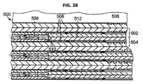
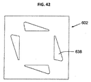
図8Aは、別の実施形態に係る、入口薄層板705の平面図である。入口薄層板705は、流体が熱交換システム110を(矢印707により示される)内方向に流れる少なくとも1つの入口流路を形成する。図8Bは、別の実施形態に係る、出口薄層板710の平面図である。出口薄層板710は、流体が熱交換システム110を(矢印712により示される)外方向に流れる少なくとも1つの出口流路を形成する。この実施形態において、流路は一般的に、図4A及び図4Bに示された実施形態の流路とは異なる経路をたどる。実際の使用時において、入口薄層板705及び出口薄層板710は、上下に積層される。
FIG. 8A is a plan view of an inlet lamina 705, according to another embodiment. The inlet laminar plate 705 forms at least one inlet channel through which fluid flows inward (indicated by arrow 707) through the
流体は、入口720において入口薄層板705の入口流路に入る。入口流路はそれから、出口薄層板710の対応する熱交換領域750bと熱連通する熱交換領域750aにおいて、複数の流路に分岐する。別の実施形態において、入口流路は、複数の流路に分岐せず、1つの流路の状態のままである。また、入口流路は、後述するように、少なくとも部分的に1つ又は複数のマイクロ流体流れ場から形成することもできる。入口流路は、熱交換領域750aを経て、ヒータ765(例えば、150WのMcMaster-Carr社製カートリッジヒータ、型番3618K451)と熱連通する弓形のヒータ領域760へと遷移する。ヒータ領域は、ヒータ765が流体を加熱する領域、及び、流体が、所定時間の間、所望の温度以上の状態で保たれる滞留チャンバの両方としての役割を果たす。
The fluid enters the inlet flow path of the inlet lamina 705 at the
流体は、入口薄層板705のヒータ領域760及び滞留チャンバから、入口位置770において、出口薄層板710に流出する。流体はそれから、出口薄層板710の熱交換領域750bに流入し、ここで、流体は、入口薄層板705の熱交換領域750aを流れる流入流体に熱を移動させる。流体はそれから、出口775において出口薄層板から出る。一実施形態において、薄層板705、710の厚みは約600μmで、マイクロ流体流路の深さは、約400μm〜600μmである。本明細書で開示されたそれぞれの実施形態において、ヒータから熱を逃がすあらゆる熱伝導性のシム材により、その上を流れる流体に熱が移動され、周囲への熱ロスが最小限となるよう、流体流路は、完全に各ヒータを取り囲んでいる。また、理想的には、各ヒータを取り囲む流路を比較的狭くして、ヒータから離れることにより生じる非均等な加熱を回避することができる。
The fluid flows from the heater region 760 and the residence chamber of the inlet lamina 705 to the
上述したように、マイクロ流体熱交換システム110は、複数の薄層板が上下に積層され拡散接着されて形成され得る。拡散接着に関する更なる情報については、米国特許出願第11/897,998号及び第12/238,404号に記載されており、これらの特許出願は、参照により本明細書に組み入れられる。一実施形態において、スタックは、一組の薄層板を複数有し、一組の薄層板は、入口薄層板305及びそれに並置された出口薄層板310を有する。並置された入口薄層板及び出口薄層板の各組は、1つの熱交換ユニットを形成する。したがって、薄層板のスタックは、各々が、出口薄層板310に連結された入口薄層板305を有する、複数の熱交換ユニットを有することができる。各薄層板の流路は、薄層板の表面をエッチングする(例えば、各薄層板の片面のみをエッチングする)ことにより形成することができる。薄層板を並置する際に、1つの薄層板のエッチング面が、隣接する隣の薄層板の非エッチング面にシールされる。これにより、好ましい熱交換状態が得られ得ると共に、(未殺菌の)流入流体と(殺菌済みの)流出流体とが隔離され得る。
As described above, the microfluidic
図9は、例示的な薄層板のスタック805を示す斜視図である。スタック805は、最上方の出口薄層板310、中間の高さの入口薄層板305a及び低い高さの入口薄層板305bを含む、スタックの様々な高さにおける部分断面図で示されている。上述したように、スタック805は、入口薄層板及び出口薄層板が交互に配されて形成されている。ヒータ292は、スタック805の全ての薄層板を通る形で、スタック805全体を貫通する切り欠きに配置されている。また、滞留チャンバ360並びに一直線に並んだ入口開口部320及び出口開口部325は、スタック805全体を貫通している。各薄層板はさらに、1つ又は複数の穴810を有することができ、これらの穴810は、薄層板の積層時に一直線に並び、位置決め支柱を挿入することが可能なシャフトを形成する。
FIG. 9 is a perspective view illustrating an exemplary stack of
スタック内の薄層板の数は、マイクロ流体熱交換システム110の所望の仕様(例えば、加熱仕様)に対応するよう変更することができる。加熱仕様は、流体の流速、ヒータの電力入力及び流入流体の最初の温度等に依存し得る。一実施形態において、スタック805は、長さ約100mm未満、最大幅寸法において幅約50mm未満、奥行き約50mm未満、そして体積約250立方センチ未満である。ただし、寸法は変更することができる。別の実施形態において、スタック805は、長さ約82mm、最大幅寸法において幅約32mm、奥行き約26mm、そして体積約69〜70立方センチ、そして乾燥時の重量約5ポンドである。ただし、寸法は変更することができる。
The number of thin plates in the stack can be varied to correspond to the desired specifications (eg, heating specifications) of the microfluidic
薄層板305及び310は、特定の用途(例えば、マイクロチャネル)に有用な形状(features)をパターン化することが可能な任意の材料とすることができる。薄層板の厚みは変更することができる。例えば、薄層板は、約200μm〜約100μmの範囲の厚みを有することとしてもよい。別の実施形態において、薄層板は、約500μm〜約100μmの範囲の厚みを有することとしてもよい。適切な薄層板の材料として、下記に限定されないが、ポリマー及び金属が含まれる。薄層板は、例えば、ステンレススチール、銅、チタン合金及び拡散接着可能なプラスチックといった、任意の拡散接着可能な金属から製造することができる。用いられる作動圧力及び動作温度及び薄層板材料の加熱流体(例えば、水)への浸出を防ぐ必要性、並びに装置は処分される前に多目的利用されるのが好ましいことから、熱交換システムは、ステンレススチール(例えば、316Lステンレススチール)から作成すれば十分であることが分かった。ただし、他の材料も、劣化すること無く、動作条件に耐えるものでありさえすれば、用いられ得る。
The
薄層板は、薄層板が正確に一直線に並ぶような形で積層される。例えば、正確に積層された場合、図9に示されるように、全ての薄層板の入口開口部320が一直線に並び、集合的に流体がシステムに流入するための入口経路を形成し、一方、出口開口部325が一直線に並び、出口経路を形成する。正確に位置決めされた薄層板のスタックはさらに、当該スタックにおいてヒータ292を連結するための、1つ又は複数のシートを有することができる。スタックにおける薄層板の正確な位置決めを補助するため、1つ又は複数の特徴(例えば、位置決め支柱及び/又は正確な位置決めの視覚的なインジケータ)が用いられ得る。スタックは、最上方の薄層板に配置された上カバー及び最下方の薄層板に配置された下カバーを有することができる。スタックはさらに、外周囲への熱ロスを防ぐための外部の断熱包装材を有することができる。
The thin plate is laminated in such a manner that the thin plate is aligned in a straight line. For example, when correctly stacked, as shown in FIG. 9, the
図10は、組立て後のマイクロ流体熱交換システム110の一例を示す斜視図である。入口/出口薄層板のスタック805は、スタック805を大気からシールするための、化学エッチングされた上カバー及び下カバーを有する。これらのカバーは、損傷及び流体を1つの状態のまま保つのに必要な動作圧力に耐えるよう、一般的に、薄層板より厚く、一実施形態においては約1mm以上の厚みとすることができる。カートリッジヒータ292は、スタック805全体にわたって延びるキャビティに取付けられる。プレート910が、スタックに(例えば、ボルトにより)固着されて、入口孔915及び出口孔920をスタック805に固定する手段となる。入口孔915及び出口孔920は、入口開口部320及び出口開口部325に連通する内腔を有する管とすることができる。
FIG. 10 is a perspective view showing an example of the microfluidic
スタックの組立て前に、カートリッジヒータを受容する各薄層板の穴は、カートリッジヒータ自体の直径よりもわずかに小さく作られている。スタック全体が組立てられた後、穴は、当該穴の内径とカートリッジヒータの外径との間の隙間嵌めにより、ヒータから殺菌装置までの最適な熱移動が実現されるような均一表面が提供されるよう、動作中のヒータの熱膨張を考慮して拡大される。上記の方法は、組立て前の時点で各シムにおける穴が厳密にカートリッジヒータのサイズに構成された場合に生じ得るシムの位置ずれの問題を防ぐ。 Prior to stack assembly, the holes in each lamina that receive the cartridge heater are made slightly smaller than the diameter of the cartridge heater itself. After the entire stack has been assembled, the holes are provided with a uniform surface that provides optimum heat transfer from the heater to the sterilizer by a clearance fit between the inner diameter of the hole and the outer diameter of the cartridge heater. Thus, the thermal expansion of the heater in operation is taken into consideration. The above method prevents shim misalignment problems that can occur if the holes in each shim are configured exactly to the size of the cartridge heater prior to assembly.
スタック805には、第二プレート925がさらに固着されている。第二プレート925は、1つ又は複数の細長いシース熱電対930をスタック805に連結するために用いられる。熱電対930は、スタック805を貫通しており、スタック805の薄層板と、ドウェルチャンバにおける流体温度をモニタするためのドウェルチャンバ領域において連通している。スタックの固体部分に挿入される熱電対は、滑り嵌めを用いて装着される。流体流路に入る熱電対は、流体漏れが起きないよう、シールされる必要がある。こうした場合、熱電対を受容する穴は、スタックが放電加工(EDM)により組立てられた後に作製される。なぜなら、こうした技術では、いくつかの流路を遮断するような大量の破片が生じ得る従来の穿孔に比べて、システムから容易に洗流することが可能な極めて少量の破片のみが生じるためである。様々なシール部材(例えば、Oリング又はガスケット)のいずれかが、スタックに取付けられた部材(例えば、プレート910及び925、熱電対930、並びに入口孔915及び出口孔920)のシール関係を実現するため、スタックに連結され得る。当然のことながら、図10に示された組立て後のマイクロ流体熱交換システム110は一例であって、他の実施形態も可能である。
A
例示的な製造工程において、薄層板のスタックは、フィクスチャ又はケーシングに配置されて、それから接着用装置(例えば、高温真空プレスオーブン又は不活性ガス炉)に配置される。こうした装置は、高温かつ高圧な環境を作り出し、それにより、薄層板同士が物理的に接着される。
In an exemplary manufacturing process, a stack of thin plates is placed in a fixture or casing and then placed in a bonding apparatus (eg, a high temperature vacuum press oven or an inert gas furnace). Such devices create a high temperature, high pressure environment whereby the thin plates are physically bonded together.
一実施形態において、スタック全体の重量は、スタックの両面から余剰材料のいくらかを除去することにより低減することができ、それにより、矩形の設置面積が、材料効率に優れた多角形の設置面積に近づく形で低減される。 In one embodiment, the weight of the entire stack can be reduced by removing some of the excess material from both sides of the stack, thereby reducing the rectangular footprint to a polygonal footprint that is more material efficient. Reduced by approaching.
図11は、別の例示的実施形態に係る、マイクロ流体熱交換システム110の概略平面図である。図11は、概略的であって、当然のことながら、流路の実際の実施形態(例えば、流路のサイズ及び形状)については変形が可能である。図11の実施形態は、移動層1115により隔離された第一流路1110及び第二流路1105を有する。流体は、入口1120において第一流路に入り、出口1125において第一流路から出る。流体は、入口1130において第二流路に入り、出口1135において第二流路から出る。第一及び第二流路は、流体が、第一方向に第一流路1110を流れ、当該第一方向とは逆の方向に第二流路1105を流れる向流の形で配されている。この場合、第一流路1110の入口1120は、装置の、第二流路1105の出口1135と同じ側に置かれている。同様に、第一流路1110の出口1125は、装置の、第二流路1105の入口1130と同じ側に置かれている。流路は、少なくとも部分的に、1つ又は複数のマイクロチャネル又は流れ場から形成することができる。
FIG. 11 is a schematic plan view of a microfluidic
図11をさらに参照すると、流体は、入口1120において第一流路1110に入り、ヒータ領域1140を通過する。ヒータは、ヒータ領域1140を通過する流体に熱を送り込むために、ヒータ領域1140と熱連通している。流体は、ヒータ領域1140を通過する前に、熱交換領域1145を通過する。熱交換領域1145は、第二流路1105を流れる流体と(移動層1115を介して)熱連通している。一実施形態において、第二流路1105を流れる流体は、それ以前に、(出口1125を通って)第一流路1110から出て、第二流路1105の入口1130に送り込まれた流体である。予め加熱された流体が第二流路1105を流れると、当該第二流路1105において、予め加熱された流体の熱エネルギーが第一流路1110を流れる流体に移動される。このように、第二流路1105における流体は、第一流路1110の熱交換領域1145における流体を、この流体がヒータ領域1140に達する前に、予め加熱する。
With further reference to FIG. 11, fluid enters
ヒータ領域1140において、ヒータは、流体を所望の温度(これは、流体の殺菌温度であってもよい)まで加熱するのに十分な熱エネルギーを出力する。ヒータ領域1140から、流体は、滞留チャンバ1150に流れ込み、ここで、滞留時間の間、所望の温度以上に加熱された状態で保たれる。流体は、好適には、滞留チャンバ1150にある間は、停滞するというよりはむしろ流動状態のまま保たれている。滞留チャンバ1150から、流体は、出口1125を通って第一流路1110から出て、第二流路1105の入口1130に送り込まれる。
In the
流体はそれから、第二流路1105を出口1135の方へ流れる。上述したように、第二流路1105は第一流路1110と、少なくとも熱交換領域1145において熱連通している。このように、予め加熱された、第二流路1105を流れる流体は、第一流路1110を流れる流体と熱連通している。予め加熱された流体が第二流路1105を流れると、当該予め加熱された流体の熱エネルギーが第一流路1110の隣接する熱交換領域1145を流れる流体に移動される。熱エネルギー交換の結果、流体は、第二流路1105を流れる際に、滞留チャンバでの温度に比べて冷却される。一実施形態において、第二流路1105における流体は、流体への細菌の侵入を防ぐことができる最低温度以上の温度まで冷却される。
The fluid then flows through the second flow path 1105 toward the
図11の装置の別の実施形態において、第二流路1105に流れ込む流体は、第一流路1110からルート変更された流体ではなく、第一流体流路1110の源と同じ又はそれと異なる源からの別個の流体の流れである。第二流路1105における流体は、第一流路1110における流体と同じ種類であっても別の種類であってもよい。例えば、水は、両方の流路を流れることとしてもよい。別の例では、水は、1つの流路を流れ、水以外の流体は、他の流路を流れることとしてもよい。第一流路に対して別の流体が第二流路を流れる本実施形態において、当該別の流体は好適には、熱交換領域1145において、第一流路1110における流体に熱を移動することができるよう予め加熱されている。
In another embodiment of the apparatus of FIG. 11, the fluid flowing into the second flow path 1105 is not fluid rerouted from the
先述した実施形態のように、図11の実施形態も、薄層板層を形成する複数の薄層板ユニットが上下に積層されて構成され得る。また、図11の実施形態は、本明細書に記載された他の実施形態と異なる又は同様の、例えば、材料、寸法、滞留時間及び温度レベルといった仕様を有することができる。
As previously described with the embodiment, the embodiment of FIG. 11 also, a plurality of thin-layer plate unit forming the thin layer plate layer may be formed by stacking vertically. Also, the embodiment of FIG. 11 can have specifications that are different or similar to other embodiments described herein, such as material, dimensions, residence time, and temperature levels.
図12に示された別の実施形態において、マイクロ流体熱交換システム110は、単一の流体を洗浄する。図12は、単一の薄層板の、例示的な流路の実施形態を示す。こうした薄層板が複数、交互配置されて、他の実施形態で先に説明したような薄層板のスタックが形成され得る。流体の浄化は、流体を殺菌するステップを含むことができる。ただし、装置が透析に用いられない場合等は、殺菌は必要ない。熱交換システムは、流入流体1205の流れを受取る。流入流体1205は、熱交換システムに入る前に分岐されている。流入流体1205aの第一部分流は、システムの一端の第一入口1210Aに入り、流入流体1205の第二部分流は、システムの反対側の他端の第二入口1210bに入る。流入流体1205の上記2つの流れは、積層された薄層板全体に、2つの流体の流れが直接接触し合わないよう交互に分配される。
In another embodiment shown in FIG. 12, the microfluidic
流入流体1205の各流れは、流路1207に入り、流路に沿って出口1215aの方へ流れる。流体の一方の流れは、入口1210aを通って入り、システムの、当該入口1210bと同じ端部に配置された出口1215aにおいて出て行き、流体の他方の流れは、入口1210bを通って入り、システムの、当該入口1210aと同じ端部に配置された出口1215bにおいて出て行く。各流路1207は、第一熱交換領域1220を有し、ここで、熱が、移動層を通って、流入流体と、スタックにおける当該薄層板の真上(又は真下)の薄層板を流れる予め加熱された流出流体との間で交換される。流体は、熱交換領域1220を流れると、熱移動により熱を受取り、ヒータ領域1225に入る前に予め加熱された状態となる。
Each flow of the inflowing fluid 1205 enters the
各流路1207で、流体はそれから、少なくとも1つのヒータ、好ましくは複数のヒータと熱連通しており、流れる流体に熱を伝達するヒータ領域1225に入る。流体は、圧力下で、他の実施形態で先に説明したように、所望の閾値の殺菌温度以上の温度まで加熱される。ヒータ領域1225はさらに、滞留チャンバとしての役割も果たす。流体は、所望の滞留時間の間、所望の温度以上の状態に保たれながら、滞留チャンバを流れる。所望の滞留時間は、例えば、流速を変化させること及び/又はヒータ領域1225内において必要な長さの蛇行流路を用いることにより実現され得る。ヒータ領域1225を出ると、流出流体は、第二熱交換領域1230に入り、ここで、流出流体は、スタックにおける当薄層板の真上(又は真下)の薄層板を流れる、流入流体との間で熱交換を行う。流出流体はそれから、出口1215A及び1215bを通って流路を出る。流出流体の2つの流れはそれから、1つの流出流体流1235に結合してから、殺菌工程により駆除された全て又は略全ての死細菌を除去する限外濾過へと進む。
In each
図13Aは、別の実施形態に係る、流体が熱交換システムを内方向に流れる入口流路を形成する螺旋状の入口薄層板を示す図である。図13Bは、流体が外方向に流れる同様の螺旋状の流路を形成する、対応する出口薄層板を示す図である。こうした入口及び出口薄層板が複数、交互配置されて、他の実施形態で先に説明したような薄層板のスタックが形成され得る。図示された薄層板は、円形の外輪郭を有する。ただし、他の実施形態と同様に、外形状は変更され得る。
FIG. 13A is a diagram showing a spiral inlet lamina forming an inlet channel through which fluid flows inwardly through a heat exchange system, according to another embodiment. FIG. 13B shows a corresponding outlet lamina that forms a similar spiral flow path through which fluid flows outward. A plurality of such inlet and outlet laminates can be interleaved to form a stack of laminates as previously described in other embodiments. The illustrated laminar plate has a circular outer contour. However, as in the other embodiments, the outer shape can be changed.
図13Aを参照すると、入口薄層板は、流入流体が入口流路に入るための入口1305を形成するヘッダを有する。入口流路は、加熱チャンバ1310が置かれた流路の中心に向かって内方向に螺旋状になっている。加熱チャンバ1310はさらに、後述するように、流体の滞留チャンバとしての役割も果たす。1つ又は複数のヒータが加熱チャンバ1310と熱連通状態で配置されて、加熱チャンバ1310において流れる流体に熱を加える。加熱チャンバ1310は、スタック内の複数の薄層板にわたって延びており、図13Bに示された出口薄層板と連通する導管を有する。流体は、加熱チャンバ1310から出口薄層板に入る。出口薄層板は、加熱チャンバ1310から出口1320の方へ外方向に螺旋状に延びる流出流路を有する。
Referring to FIG. 13A, the inlet lamina has a header that forms an
使用に際し、流体は、図13Bに示された入口1305を通って入口薄層板の入口流路に入る。流体はそれから、螺旋状の入口流路に沿ってヒータチャンバ1310の方へ流れる。先述した実施形態と同様に、流入流体の温度は、入口薄層板の真上又は真下に配置された出口薄層板を流れる予め加熱された流体より低い。流体が入口流路を流れると、流体は、出口薄層板の出口流路を流れる予め加熱された流体から熱を受取る。これは、流体を、当該流体が加熱チャンバ1310に流れ込む前に、予め加熱する働きをする。流体はそれから、加熱チャンバ1310に流れ込み、ここで、流体は1つ又は複数のヒータから熱を受取る。
In use, fluid enters the inlet flow path of the inlet lamina through the
流体は、加熱チャンバ1310において、他の実施形態で先に説明したように、圧力下で、所望の閾値の殺菌温度以上の温度まで加熱される。先述したように、加熱チャンバ1310はさらに、流体の滞留チャンバとしての役割も果たす。流体は、所望の滞留時間の間、所望の温度以上の状態に保たれながら、滞留チャンバを流れる。他の実施形態と同様に、所望の滞留時間は、例えば、流速を変化させること及び/又はヒータチャンバ1310内において必要な長さの蛇行流路を用いることにより実現され得る。ヒータチャンバを出ると、流出流体は、図13Bに示されたような出口薄層板の出口流路に入る。流出流体は、加熱チャンバ1310から、螺旋状の流路に沿って出口1320の方へ外方向に流れる。入口薄層板の螺旋状の流路は、移動層を介して、出口薄層板の螺旋状の流路と熱連通している。流出流体が螺旋状の流路に沿って流れる際、当該流出流体は、スタックにおける該当薄層板の真上(又は真下)の入口薄層板を流れる流入流体との間で、熱交換を行う。流出流体はそれから、出口1320を通って薄層板のスタックから出てから、殺菌工程により駆除された全て又は略全ての死細菌を除去する限外濾過へと進む。
The fluid is heated in the
3.[マイクロ流体熱交換システム:制御システム] 3. [Microfluidic heat exchange system: control system]
マイクロ流体熱交換システム110は、システム全体の流体の流れに関する1つ又は複数の側面(例えば、流体の流速、流体の温度及び/又は圧力並びに流体の化学的濃度等)を調節及び/又は制御するよう適合された制御システムを有するか、あるいは当該制御システムに連結することができる。図14は、マイクロ流体熱交換システム110に通信可能に連結された例示的な熱制御システムを示す概略図である。ヒータ制御システム1005は、ヒータ制御ユニット1020に通信可能に連結された少なくとも1つの電源1015を有する。ヒータ制御ユニット1020は、制御論理ユニットに連通されている。熱制御ユニット1020は、ヒータへの電力供給を、各ヒータに対して個別的に又はヒータ群に対して集合的に、制御するよう適合されている。このことにより、マイクロ流体熱交換システム110に供給される熱の一時的及び空間的な制御が可能となる。
The microfluidic
ヒータ制御システム1005は、1つ又は複数の温度センサ1010を有することができ、これらは、マイクロ流体熱交換システム110内又はその周囲に配置されて、流体流路の1つ又は複数の位置における流体温度を検知する。センサの種類は変更することができる。一実施形態において、1つ又は複数の熱電対がセンサ1010として用いられる。センサ1010は、ヒータ制御ユニット1020及び制御論理ユニット1025と連通されて、温度フィードバックループを形成する。ヒータ制御システム1005は、システムにおける流体温度のフィードバック制御を実現して、例えば、流体が必要とされる殺菌温度まで加熱されること及び/又は流体が過熱状態又は加熱不足状態にならないことを確実にする。例えば、ヒータ制御ユニット1020は、制御論理ユニット1025と共に、ヒータのうち1つ又は複数に対する電力を、検知温度に基づいて、流体流路の1つ又は複数の位置において所望の温度プロフィールが得られるように調整することができる。ヒータ制御システム1005は、必要に応じて流体の他のパラメータをモニタ及び調整するために、他の種類のセンサ(例えば、圧力センサ及び流速センサ等)を有することができる。
The
ヒータ制御システム1005はさらに、温度が望ましくないレベルになると、ユーザ又は遠隔地のシステム機能モニタに対してそれを通知するための、1つ又は複数のアラーム(例えば、視覚的並びに/あるいは聴覚的な表示及び/又は通信信号)を生成するよう構成することができる。例えば、制御ユニット1020は、例えば、滞留チャンバ温度が維持されるような1つ又は複数の温度設定リミットを有することができる。リミットを超える、すなわち、温度が最低動作リミットを下回るか、又は最高動作リミットを上回ると、制御システムは、オペレータにより問題が診断され、修復されるまで、ヒータを迂回し、アラームを鳴らして、水浄化システム全体の動作を停止させ得る。この点に関し、制御システム1005は、データベースを備えた報告ユニット1030を有することができる。報告ユニット1030は、センサからのデータをログ及び記憶し、そうしたデータをユーザ又は遠隔地のシステムモニタに送信するよう構成されている。
The
4.[流体浄化システム:起動及びシャットダウン] 4). [Fluid purification system: Startup and shutdown]
流体浄化システムが透析に用いられる場合は、熱交換システム110内及び熱交換システム110の下流の部品全体の両方において、流体流路の細菌汚染を防ぐことが重要である。この点に関し、殺菌装置としての役割を果たす熱交換システム110は、好ましくは、流体浄化システムの起動時において、清潔な流体の流れを確実にすると共に、シャットダウン時(すなわち、ヒータ292の電源遮断時)において、下流の部品の細菌汚染を防ぐか、又は、少なくとも汚染作用を緩和するよう動作される。
When a fluid purification system is used for dialysis, it is important to prevent bacterial contamination of the fluid flow path both within the
一実施形態において、起動時における清潔な流体の流れは、ヒータ292の電源投入時にまず、熱交換システム110に殺菌液を流通させることにより実現される。殺菌液体はそれから、熱交換システム110が所望の動作温度に達するまで、熱交換システム110の下流の全ての部品を流れる。熱交換システム110が所望の動作温度に達すると、熱交換システム110への流体の流れは、逆浸透システム125からの水に切り替わる。水は、(所望の動作温度に達した)熱交換システム110を通過して、熱交換システム110の流路から殺菌液を洗流する。様々な殺菌溶液を用いることができる。例えば、殺菌溶液は、1%のクロラミンを含む水混合物又は何らかの他の周知の殺菌性水添加物であってもよい。
In one embodiment, a clean fluid flow at startup is achieved by first flowing a sterilizing solution through the
流体浄化システムは、次のようにシャットダウンされ得る。ヒータ292の電源は、流体の流れが熱交換システム110で維持された状態で遮断される。代替的に、殺菌液は、熱交換システム110が略室内温度の状態に達するまで、熱交換システム110で流通され得る。このように、流路は、熱交換システム110のシャットダウン時において殺菌済みの状態のまま保たれている。熱交換システム110の流路はそれから、熱交換システム110の流路において存在する殺菌液と共に閉鎖又はロックダウンされる。殺菌液の存在により、シャットダウン時における細菌汚染の可能性が著しく低減される。
The fluid purification system can be shut down as follows. The power source of the
別の実施形態において、1つ又は複数の弁が流体浄化システムの流路に配置される。弁は、起動時における所望の殺菌状態が得られるまで、溶液が、ポンプ150、熱交換システム110及び下流の部品を通るループを、再循環ループの形で、循環的に流れることを可能にする。弁はそれから、殺菌液がシステムから洗流され得るように設定される。高温の(例えば、摂氏100度未満の)殺菌液を、下流の部品及び/又は電源の入れられていない熱交換システム110に循環させる機能を実現するために、例えば、(熱交換機能を有さない)マイクロチャネル流体ヒータといった、補助的な部品が組み込まれ得る。殺菌液は、流路及び部品を、何週間及び/又は何ヶ月もの間、清潔な状態で保つために、起動又はシャットダウンの工程において用いられ得る。熱交換システム110が動作温度に達する前に、細菌が流体洗浄システムに入ることを防ぐための別の方法として、起動時に、殺菌液の再循環ループが用いられる。また、起動又はシャットダウンの工程の間の品質制御を確実にするための方法を実現するような温度検知能力を備えたタイミング制御論理が用いられ得る。制御論理は、熱交換システム110又はヒータが予め設定された温度に達して初めて流れをスタートさせるよう構成され得る。
In another embodiment, one or more valves are placed in the fluid purification system flow path. The valve allows the solution to circulate in a loop through the
流路は、清浄用及び/又は殺菌用の流体を流路に循環することが可能な、1つ又は複数の迂回循環経路を有することができる。循環経路は、開ループの流れとすることができ、循環経路を流れる流体は、使用された後システムから放出可能である。別の実施形態において、循環経路は、閉ループの流れとすることができ、循環経路を流れる流体は、システムから放出不可能である。代替的に、システムは、開循環経路及び閉循環経路の両方を有することとしてもよい。 The flow path can have one or more detour circulation paths that can circulate cleaning and / or sterilizing fluid into the flow path. The circulation path can be an open loop flow, and the fluid flowing through the circulation path can be discharged from the system after it has been used. In another embodiment, the circulation path can be a closed loop flow and fluid flowing through the circulation path cannot be discharged from the system. Alternatively, the system may have both an open circuit path and a closed circuit path.
5.[透析液準備システム] 5. [Dialysate preparation system]
水は、水浄化システム5を出て、透析液準備システム10に流れ込む際は、殺菌された状態である。透析液準備システム10は、殺菌水を、供給される原溶液と混合して、透析液を生成するよう構成されている。図15は、透析液準備システム5を示す高水準概略図である。ただし、図15の実施形態は、例示的であって、当然のことながら、本発明の範囲には変形が含まれる。
When the water leaves the water purification system 5 and flows into the
透析液準備システム10は、浄水と混合される酸性の透析液原液の供給源と流体接続した酸ポンプ170を有する。水は、水浄化システム5から、酸ポンプ170に流れ、酸ポンプ170は、酸性原液を水に送り込む。(酸と混合された)水はそれから、第一混合チャンバ172に流れ込む。第一混合チャンバ172は、例えば、乱流を生じさせることにより、水を酸と混合する。第一混合チャンバ172から、酸性水混合物は、重炭酸ポンプ174の方へ流れる。センサ(例えば、伝導率センサCS)が、第一混合チャンバ172の下流に配置され得る。伝導率センサCSは、混合物の電解質レベルを検知するよう構成されている。伝導率センサCSは、酸ポンプ170及び制御システムと閉ループの形で連通しており、制御システムは、酸ポンプの速度を調節して、水に対する所望のレベルの酸のポンピングを実現することができる。
The
重炭酸ポンプ174は、透析液を生成するのに十分なレベルの重炭酸原液を、酸性水混合物に送り込む。結果として得られる流体の混合物は、第二混合チャンバ177に流れて、透析液として、第二混合チャンバ177から出る。また、別のセンサ(例えば、伝導率センサCS)が、第一混合チャンバ172の下流に配置され得る。第二伝導率センサCSは、重炭酸ポンプ177と閉ループの形で連通され得る。透析液はそれから、流れバランスシステム及び透析装置の方へ流れる。
6.[透析装置] 6). [Dialysis device]
図16は、透析装置15を示す概略断面図であって、透析装置15には、血液流路205を有する血液室と、半透明膜215から成る移動層により隔離された、透析液流路210を有する透析液室とが規定されている。一実施形態において、透析装置は、例えば、マイクロ流れ場及び/又はマイクロチャネルといった、1つ又は複数のマイクロ流体流路を有する。以下、マイクロ流れ場及び/又はマイクロチャネルを利用した透析装置の例示的実施形態について説明する。まず、以下に、流れ場透析装置から成る透析装置の例示的実施形態について説明する。ただし、本明細書に記載の透析システムは、様々な市販の透析装置を含む任意の様々な透析装置と用いられ得る。
FIG. 16 is a schematic cross-sectional view showing the
(患者からの)血液は、血液入口216を通って血液流路205に入り、血液流路205を流れて、血液出口217を通って出る。透析液は、流体入口218を通って透析液流路210に入り、透析液流路210を流れて、流体出口219を通って出る。半透明膜215は、1つ又は複数の物質が、血液流路205における血液から透析液流路210における透析液に、又はその逆に、移動するのを可能にするよう構成されている。
Blood (from the patient) enters blood channel 205 through blood inlet 216, flows through blood channel 205, and exits through
半透明膜215として用いられ得る材料として、例えば、ポリマー、共重合体、金属、セラミック、合成物及び/又は液体膜が含まれる。合成膜の一例として、例えば、ガンブロメディカル(Gambro Medical)社製のAN69フラットシート膜といった、ポリスルホン‐ナノ結晶セルロース合成膜が挙げられる。ガス‐液体コンタクター膜は、液体とガスとの間の物質の移動(例えば、血液の酸素化)のために用いることができ、当該膜は、酸素が、酸素又は酸素富化空気から血液に移動され、二酸化炭素が、血液からガスに移動される形での、二酸化炭素及び酸素の移動を可能にする。また、流体膜も用いられ得る。流体膜は、スルーカットマイクロチャネルを備えた薄層板を有し、マイクロチャネルは、流体並びに当該マイクロチャネルにおける流体を保持するよう配置された第一及び第二膜支持体を有する。
Materials that can be used as the
血液及び透析液は、透析装置15を流れる際に、血液がある方向に血液流路205を流れ、透析液がそれとは逆の方向に透析液流路210を流れる向流の形で流れ得る。透析装置15は、向流の文脈で説明されるが、交差流の形を用いることもできる。血液及び水が膜215の傍を流れると、血液透析が生じる。透析装置15はさらに、膜215の両側の圧力差により、流体及び溶解溶液が血液から膜215を通って透析液に移動する限外濾過を行うよう構成されている。
When blood and dialysate flow through the
透析装置15はさらに、半透明膜215を通じた溶液の移動が、拡散というよりむしろ対流に支配される血液透析濾過を行うよう構成されている。血液流路205と透析液流路210との間の流体静力学的な正の圧力差は、水及び溶液を、血液流路から半透明膜215を通って流体流路へ移動させる。小分子及び高分子の両方の溶液が、流体と共に、半透明膜215を通って移動される。一般的な血液透析濾過法において、水及び溶液の移動方向は、血液から透析液に水及び溶液を移動させる方向と、透析液から血液に水及び溶液を移動させる方向とを繰り返す。所定の時間の間、血液から透析液への流体のネットロス及びネットゲインはゼロである。ただし、上記の時間内の不連続な時間の間、血液から透析液への流体のネットロス及び透析液から血液への流体のネットゲインが生じることもある。
The
なお、透析装置15は、マイクロ流体流れ場又はマイクロ流体チャネルを利用することができる。以下、透析装置として用いられるマイクロ流体システムの例示的実施形態について説明する。
The
7.[流れバランスシステム] 7). [Flow balance system]
流れバランスシステム20は、様々な種類の透析(例えば、血液透析、限外濾過及び血液透析濾過)を実現するために、透析装置15へ/からの透析液の流れを調節するよう適合されている。流れバランスシステム20は、透析液を透析装置に送り込む第一ポンプ及び透析液を透析装置から送り出す第二ポンプを有する。システムはさらに、詳細に後述するように、限外濾過あるいは血液透析濾過又はそれら両方に対する向上された制御を行う第三ポンプを有する。
The
図17は、透析装置15を有する流れバランスシステム20を示す概略図である。システムには、実行される血液透析の種類に対して向上された制御を行うための3つ以上のポンプが配置されている。これら3つのポンプの相対的なポンプ速度を変化させることにより、オペレータは、血液濾過のレベルを変化させることができ、また、血液の限外濾過及び血液透析濾過を選択的に実施することができる。
FIG. 17 is a schematic diagram showing a
流れバランスシステム20は、複数の流体流路を形成する配管を有する。配管は、流体(例えば、透析液)が流通可能な任意の導管とすることができる。流体流路は、流体(例えば、未使用の透析液)が透析液準備システム10から透析装置15の方へ流れる入口流路250を有する。流体を透析装置15の方へ所望の流速で送り込むために、少なくとも第一ポンプ255が、入口流路250に沿って、又は入口流路250と連通状態で配置される。流体流路には、流入流体の1つ又は複数の特徴(例えば、圧力、流速、温度及び伝導率等)を検知するための1つ又は複数のセンサSが連結され得る。また、流体流路には、管を流れる流体にアクセスするための1つ又は複数のサンプルポートPが連結され得る。図17には、流体流路の特定の位置に連結されたセンサS及びサンプルポートPが示されている。ただし、センサS及びサンプルポートPの数及び位置は変更することができる。
The
流体流路はさらに、使用済みの透析液が透析装置15から出て1つ又は複数のドレイン25の方へ流れる出口流路260を有する。いくつかの実施形態において、透析装置を出る透析液は、ドレイン25に達する前に、システムにおける他の流入流体(例えば、熱交換及び浄化システムに入る水流)を予め加熱するために用いられ得る。出口流路260は、主要出口流路260a及び補助出口流路260bを含む、2つ以上の出口流路に分岐する。透析液を主要出口流路260aから透析装置15の外へ送り出すために、少なくとも第二ポンプ265が、主要出口流路260aに沿って、又は主要出口流路260aと連通状態で配置される。
The fluid flow path further includes an
第三ポンプ270は、補助出口流路の第二弁285に沿って、又は第二弁285と連通した形で配置される。第三ポンプ270は、さらに詳細に後述するように、血液透析、限外濾過及び血液透析濾過を含む、様々な種類の透析の実現に応じて、流体流路を通る流体の流れを増大させて、例えば、入口流路250と出口流路260との間の流速差を選択的に生じさせるため等に用いられ得る。第三ポンプは、システムが透析モードの時は、透析液を流体流路に送り込む。第三ポンプはさらに、システムが他のモード(例えば、キャリブレーションモード又は清浄モード)の時は、別の流体(例えば、水又は消毒剤)を送り込み得る。第三ポンプ270はさらに、さらに詳細に後述するように、第一ポンプ255及び第二ポンプ265の流速をキャリブレートするために用いられ得る。
The
図18に示された別の実施形態において、第三ポンプ270は、透析装置15の入口218上流にある入口流路250に沿って配置されている。本実施形態において、第二出口流路260は、第一ポンプ255の下流かつ第一弁280の上流の位置において、入口流路250から分岐している。第三ポンプ270は、流体を、ドレイン25の方へ送る。図18の第三ポンプ270は、新鮮な未使用の透析液をドレイン140に送り込むのに対し、図17の第三ポンプは、使用済みの透析液をドレイン25に送り込むため、図17の実施形態は、図18の実施形態よりも効率的であると考えられる。別の実施形態において、第三ポンプ270及び第二ポンプ265はいずれも、分岐を有さない1つの流出流路に沿って配置される。
In another embodiment shown in FIG. 18, the
様々な種類のポンプを、第一、第二及び第三ポンプとして用いることができる。一実施形態において、ポンプは、摂動(nutating)ポンプである。他の実施形態において、ポンプは、回転ローブポンプ、一軸ねじポンプ、回転歯車ポンプ、ピストンポンプ、ダイアフラムポンプ、ねじポンプ、歯車ポンプ、油圧ポンプ、ベーンポンプ、再生(渦流)ポンプ、ぜん動ポンプ又はこれらの組み合わせとすることができる。また、他の種類のポンプを用いてもよい。第一ポンプ255及び第二ポンプ265は、ポンプのストロークとポンプで送られる流体量との間の同期性を確実にするために、共通のシャフトにより作動され得る。ただし、理解されるように、第一ポンプ255及び第二ポンプ265は、互いに完全に独立したものとしてもよい。
Various types of pumps can be used as the first, second and third pumps. In one embodiment, the pump is a nutating pump. In other embodiments, the pump is a rotary lobe pump, single screw pump, rotary gear pump, piston pump, diaphragm pump, screw pump, gear pump, hydraulic pump, vane pump, regenerative (vortex) pump, peristaltic pump, or combinations thereof It can be. Also, other types of pumps may be used. The
上述したように、流れバランスシステム20の流体流路を形成するために、任意の様々な流体導管を用いることができる。一実施形態において、流体流路の少なくとも一部が、1/8インチ〜1/2インチの内径を有する管から形成される。管における流速は、約50ml/min〜約1000ml/minの範囲とすることができる。また、一実施形態においては、流速は、約100ml/min〜約300ml/minの範囲とすることができる。
As described above, any of a variety of fluid conduits can be used to form the fluid flow path of the
図18を再び参照すると、流体流路はさらに、入口流路250と出口流路260とを直接的に流体接続させる迂回流路275を有する。迂回流路275の例示的な目的とは、流体が、例えば、システムの洗浄、清浄又はキャリブレーションのために、透析システムに/から流れ、透析装置15を迂回可能な流体流路を提供することである。一実施形態において、入口流路250と迂回流路275との合流点は、透析装置15の流体入口120の上流に位置し、迂回流路275と出口流路との合流点は、透析装置15の流体出口125の下流に位置する。ただし、透析装置15における迂回を生じさせるために、迂回流路275の他の実施形態を用いることも可能である。
Referring back to FIG. 18, the fluid flow path further includes a
第一弁280は、入口流路250と迂回流路275との合流点に置かれている。第二弁285は、迂回流路275と出口流路260との合流点に置かれている。第一弁280及び第二弁285は、流体流路の流体の流れを選択的に調節するために用いられ得る三方弁(例えば、ソレノイド弁)である。すなわち、第一弁280は、(1)第一弁が、全ての流入流体を入口流路250に沿って(図17の矢印Aにより示される)透析装置15の方へ方向付け、当該流入流体が迂回流路275に流れ込むのを防ぐ透析設定、又は(2)第一弁280が、全ての流入流体を(図17の矢印Bにより示される)迂回流路275の方に方向転換させ、当該流入流体が第一弁を超えて透析装置15の方へ流れるのを防ぐ迂回設定を含む、2つ以上の設定のいずれかにセットされ得る。
The
また、第二弁285は、(1)第二弁285が流入流体を、迂回流路275から(図17の矢印C出口流路260により示される)出口流路260の方へ方向付けるバイパス設定、又は(2)第二弁285が、迂回経路275からの流れを遮断して、透析装置出口125からの流出流体が出口流路260に沿って(図17の矢印Dにより示される)外方向に流れ続けるようにする透析設定を含む、2つ以上の設定のいずれかにセットされ得る。第一弁280及び第二弁285は一般的に、両方が同時に、迂回設定又は透析設定のいずれかにセットされる。システムは、確実に、第一及び第二が、相容れない設定にセットされないようにするための制御・安全システムを有することができる。
Also, the
図17及び図18に示された透析システムの様々な部品の配置は、例示的であって、他の配置も可能である。例えば、流路及びポンプは、図17及び図18に示された位置とは異なる流路沿いの位置に置かれ得る。一実施形態においては、第三ポンプ270が、流路の、透析装置15の上流かつ第一弁280の下流の位置に置かれるか、又は、第三ポンプが、透析装置15の下流かつ第二弁285の上流に置かれ得る。また、システムは、3つ以上のポンプを用いることとしてもよい。
The arrangement of the various components of the dialysis system shown in FIGS. 17 and 18 is exemplary and other arrangements are possible. For example, the flow path and pump may be placed at a location along the flow path that is different from the positions shown in FIGS. In one embodiment, the
8.[流れバランスシステム:限外濾過を行わない血液透析を実現するポンプ動作] 8). [Flow balance system: pump operation to achieve hemodialysis without ultrafiltration]
図17を再び参照すると、流れバランスシステム20は、入口流路250の流速が、出口流路260の流速と同じ又は略同じである場合に、限外濾過を行わない血液透析を実現する。すなわち、限外濾過を行わない血液透析は、ある時間の間、入口流路250を通って透析装置15に流れ込む透析液量が、出口流路260を通って透析装置から流れ出る透析液量と略同じである場合に実現される。これは、入口流路250で第一流速が実現されるよう、第一ポンプ255を第一ポンプ速度で動作すると共に、出口流路260で入口流路250の流速と同じ流速が実現されるよう、第二ポンプ265及び第三ポンプ270を各々の速度で動作することにより実現することができる。
Referring again to FIG. 17, the
一実施形態において、システムは、3つのポンプ全てをアクティブ状態で略連続的に血液透析の手順全体において用いる血液透析法を行う。システムは、入口流路250及び出口流路260で、同一流速の所望の均衡が実現されるよう、第三ポンプ270のポンプ速度を調整する。本実施形態において、第一ポンプ255、第二ポンプ265及び第三ポンプ270はいずれも、血液透析の手順全体においてアクティブであり、第一及び第二ポンプは、異なるポンプ速度で動作され、第三ポンプは、入口流路250及び出口流路136の均衡のとれた流速を実現するようなポンプ速度で動作される。第三ポンプは一般的に、第一ポンプのポンプ速度と第二ポンプのポンプ速度との間の差に等しいポンプ速度で動作される。このように、第二ポンプ265及び第三ポンプ270は集合的に、入口流路250における流速と同じ流速を出口流路260において実現する。
In one embodiment, the system performs a hemodialysis method that uses all three pumps in an active state substantially continuously throughout the entire hemodialysis procedure. The system adjusts the pump speed of the
例えば、透析装置で100ml/minの所望の流速を実現するためには、第一ポンプ255は、入口流路250で100ml/minの流速を実現するようにセットされ、第二ポンプ265は、意図的に第一ポンプ255と均衡にならないよう、例えば、80ml/minのみの流速を実現するようにセットされる。これにより、第一ポンプと第二ポンプとの間に20ml/minの流速の差が生じ得る。第三ポンプ270のポンプ速度は、第一及び第二ポンプの流速の差に等しい20ml/minの流速を実現するようにセットされる。このように、流速が透析装置にわたって均衡化されるよう、第二ポンプ265及び第三ポンプ270は集合的に、入口流路250における流速と等しい100ml/minの流速を出口流路において実現する。こうした状況下では、血液透析を行う拡散により、廃液が、透析装置の血液流から半透明膜を通って透析液に移動する。
For example, to achieve a desired flow rate of 100 ml / min with a dialyzer, the
入口流路250及び出口流路260の流速は、1つ又は複数のセンサSを用いて測定され得る。一実施形態において、センサは、入口流路250及び出口流路260の流速を直接的に測定する流速センサである。別の実施形態において、センサは、入口流路250の流体圧力及び出口流路260の流体圧力に関する表示を行う圧力センサである。流体圧力は、流路の流速の関数であり、したがって、流速の非直接的な測定を可能にする。入口流路250における流体圧力が出口流路260における流体圧力と等しい場合、これは、入口流路と出口流路との間で流速の均衡がとれていることを示す。入口流路250における流体圧力が、出口流路260における流体圧力より低い場合、これは、入口流路250における流速が出口流路260における流速より小さいことを示す。入口流路250における流体圧力が、出口流路260における流体圧力より高い場合、これは、入口流路250における流速が出口流路260における流速より大きいことを示す。流体流路のシステムは、流体流路内の圧力の極端な変動を抑制するための、1つ又は複数の抑制機構を有することができる。
The flow rates of the
後者の2つの状況においては、入口流路250と出口流路260との間で均衡のとれた流速が実現されるよう、第三ポンプ270のポンプ速度が、入口及び出口流路の圧力差に応じて、例えば、キャリブレーション法により調節され得る。キャリブレーション法は、図19に示され、さらに詳細に後述されるように、キャリブレーションモードにおけるシステムにおいて、任意に行うことができ、その際、流体が迂回流路275に流れて透析装置15を迂回するよう、第一及び第二弁がセットされる。キャリブレーション法が、透析装置15を迂回させることにより実行され、圧力差が入口流路及び出口流路の間に検知された場合、第三ポンプ270の流れは、当該第三ポンプをオン又はオフする必要無しに、当該第三ポンプの速度を増加又は減少させて、出口流路260において所望の流速が実現されるよう、「オンザフライ」で調節され得る。この点において、流速の自動的な均衡化を実現するために、圧力センサS及び3つのポンプ並びに弁280及び285は、閉ループ制御システムにおいて接続され得る。
In the latter two situations, the pump speed of the
別の実施形態において、入口流路250及び出口流路260の間で均衡化された流速は、理論的には、入口流路250及び出口流路260で同じ流速が実現されるよう、少なくとも第一ポンプ255及び第二ポンプ265を同じポンプ速度で動作させることにより実現される。第一ポンプ255及び第二ポンプ265の流速を等しくすることは、理論的には可能ではあるが、様々な要因により、入口流路250における実際の流体の流速は、出口流路260における実際の流体の流速とは異なる。そうした要因には、例えば、エアトラップ、ハードウェアの摩耗及び流体漏れが含まれ、これらは、第一及び第二ポンプの流速を、時間の経過にしたがって、予め設定された値又は所望の値から逸脱させる。透析システムにおける一般的な技術は、上記の種類の要因に対して、流れバランスを修正することが不可能である。
In another embodiment, the flow rate balanced between the
したがって、第一及び第二ポンプのみを使用するだけでは、均衡化された流速が容易に実現されない場合が生じ得るため、入口流路250と出口流路260との間で流速を均衡化させるための修正が必要とされている。流体の流速が異なる場合、第三ポンプ270を用いることができる。第三ポンプ270は、アクティブ状態になると、入口流路250の流体の流速と出口流路260の流体の流速との間の変化量に等しい速度で流体を補助出口流路260bに送ることにより、上述したような異なる流速を修正する。システムは、好適には、第一ポンプ255が必ず、第二ポンプ265より高い速度で流体を送り、第一ポンプ255が第二ポンプ265より少量の流体を送るのを防ぐよう構成されている。システムは、好適には、制御システムを有し、当該制御システムは、第一ポンプ255が意図せず、第二ポンプ265より低い速度で流体を送るという事態を検知し、アラームを鳴らすか、又はそうなった場合にシステムを透析モードから切り替える。
Therefore, to use only the first and second pumps, a balanced flow rate may not be easily achieved, so that the flow rate is balanced between the
ある流速修正法によれば、センサS(図17参照)が、入口流路250及び出口流路260の流速を測定するために用いられる。入口流路250における流速と出口流路260における流速とが比較される。これらの流速が異なる場合は、第三ポンプ270が非アクティブ状態からアクティブ状態となり、流体を補助出口流路の第二弁285に、出口流路260における全体的な流速が入口流路250における流速と同じになるように選択された速度で流し込む。流速の均衡化が回復される(例えば、入口流路250及び出口流路260の両方において、同じ流体圧力が存在することにより、明らかになり得る)までの間、第一ポンプ255及び/又は第二ポンプ265のストローク量を調整するために、例えば、サーボ機構といった機構が用いられ得る。
According to one flow rate correction method, a sensor S (see FIG. 17) is used to measure the flow rates in the
上述したように、センサSは、閉ループシステムにおいて、制御システム及び3つのポンプに通信可能に連結されている。制御システムは、ハードウェア及び/又はソフトウェアを有し、当該ハードウェア及び/又はソフトウェアは、第三ポンプ270を自動的にアクティブ及び/又は非アクティブ状態にするか、又は、必要に応じて、第三ポンプのポンプ速度を、所定の値に対する検知流速の差又はそれらの変化に応じて調整し、入口流路250及び出口流路260の流速を均等にする。当然のことながら、流速は、直接的に測定される替わりに、他の測定値(例えば、入口及び出口流路における流体圧力)を用いて、非直接的に算出され得る。この点に関し、入口流路及び出口流路における流体圧力は、所定の値に対する圧力の検知可能な変化又はそれらの変動に応じて測定され得る。流路は本質的には、第一ポンプ255及び第二ポンプ265の流速にわずかな差があっても、大きさが正又は負に関わらず、高速な圧力変化が生じるようなノンコンプライアンスなものとして適合させることができる。
As described above, the sensor S is communicatively coupled to the control system and the three pumps in a closed loop system. The control system has hardware and / or software that automatically activates and / or deactivates the
システムは、最初に及び/又は定期的にキャリブレーションモード(UF確認モードとも呼称され得る)で作動され、当該モードにおいて、第一弁280及び第二弁285は、システムを流れる流体が迂回流路275を介して透析装置15を迂回する「迂回設定」にセットされた状態で、流体(透析液又はそれ以外であり得る)が流路を流れる。図19は、透析装置15が迂回される上記キャリブレーションモードで動作されたシステムを概略的に示す図である。システムが3つのポンプ全てを略連続的に血液透析の手順全てにおいて用いる本実施形態において、第一及び第二ポンプはまず、意図的に、均衡のとれていない流速を実現するようにセットされる。そして、流路において、入口流路の流体の流速又は圧力及び出口流路の流体の流速又は圧力を測定するために、センサSが用いられる。第三ポンプ270はそれから、入口流路250と出口流路260との間で略均衡のとれた流速が実現されるようなポンプ速度にセットされる。
The system is initially and / or periodically operated in a calibration mode (which may also be referred to as a UF confirmation mode), in which the
他の実施形態において、第一ポンプ255及び第二ポンプ265はまず、最初は非アクティブ状態である第三ポンプ270の補助を必ずしも必要とすること無く、等しい流速を実現するようにセットされる。そして、流路において、入口流路の流体の流速及び出口流路の流体の流速を測定するために、センサSが用いられる。流体の流速が等しい場合は、第三ポンプ270は、非アクティブ状態のまま保たれる。一方、流体の流速が等しくない場合は、第三ポンプ270は、入口流路250及び出口流路260の流速の相違を補う速度で作動される。上述したように、第三ポンプ270は、流速センサ及び/又は圧力センサを備えた閉ループ関係において動作され得る。図20には、第三ポンプ270が極めて細い線で示されており、これは、第三ポンプが、入口流路250と出口流路260との間に流速差があるか否かに応じて、作動される又はされないものであり得ることを示している。システムは、3つのポンプ全てが連続的に動作する場合に、より効率的に運転され得るため、第三ポンプのアクティブ化及び非アクティブ化を必要としないキャリブレーション法が好ましい。
In other embodiments, the
キャリブレーションの工程が完了すると、弁280及び285は、流体が源110から入口経路250を通って透析装置15に流れ透析装置を15を出て出口経路260に流れる「透析設定」にセットされ得る。システムがそのように構成された場合、入口流路及び出口流路を通して透析液を透析装置15に/から流れさせ、血液を透析装置に/から流れさせることにより、当該システムを透析に用いることができる。透析時は、先述したキャリブレーション手順が、例えば、所定の間隔で定期的に繰り返されて、確実に、入口及び出口流路の流速が所望の範囲内に保たれる。
Upon completion of the calibration process,
一実施形態において、キャリブレーションは、透析セッションの始まりのみにおいて実行される。より好ましい実施形態において、キャリブレーションは、透析セッションにおいて定期的に実行され、確実に、所望の流れの均衡がセッションを通じて保たれる。制御システムは、流入する流れを制御する弁280及び285の間で、透析設定と迂回設定とを繰り返して、透析セッションを別途遮断すること無く、キャリブレーションステップを実行することができる。キャリブレーション工程において、透析液が透析装置15を迂回する場合は、その間に新鮮な透析液が透析装置15に供給されることはないため、透析装置を通過する血液はわずかに冷却され得るものの、当該血液の透析が妨害されることはない。キャリブレーションステップが、キャリブレーションの合間の時間に比べて比較的短時間行われ得る限り、キャリブレーションは、患者に供給される透析の品質に重要な影響を与えない。一実施形態において、透析システムは、1分間のキャリブレーションの後、60分間の透析装置への透析液の供給を行う、というサイクルを繰り返すこととしてもよい。一実施形態において、透析システムは、30秒間のキャリブレーションの後、120分間の透析装置への透析液の供給を行う、というサイクルを繰り返すこととしてもよい。
In one embodiment, the calibration is performed only at the beginning of the dialysis session. In a more preferred embodiment, calibration is performed periodically in a dialysis session to ensure that the desired flow balance is maintained throughout the session. The control system can repeat the dialysis and bypass settings between the
図20は、透析モードで動作されたシステムを概略的に示す図である。第三ポンプ270及び補助出口流路の第二弁285を通る流れの矢印291は、極めて細い線で示されており、これは、第三ポンプ270が、システムが透析モードである間は、作動される又はされないものであり得ることを示している。第三ポンプ270は、当該第三ポンプ270が入口流路及び出口流路の流速を等しくするために必要な場合は、アクティブ状態にされ得る。あるいは、入口及び出口流路の流速は、第三ポンプ270の補助の必要無く、等しくすることができる。こうした場合は、第三ポンプ270は、非アクティブ状態のまま保たれる。
FIG. 20 schematically shows a system operated in dialysis mode. The
9.[流れバランスシステム:限外濾過を実行するポンプ動作] 9. [Flow balance system: Pump operation to perform ultrafiltration]
透析システムは、透析装置全体で不均衡な流速が存在し、入口流路250の流速が出口流路260の流速と異なる状況において、限外濾過を実現する。出口流路260の流速が入口流路250の流速より大きい場合は、透析装置15は、不均衡な流速を補うために、対流による手法により、血液から流体を半透明膜を通して移動させる。一実施形態において、システムは、3つのポンプ全てを略連続的に手順全体において用い、第三ポンプ270のポンプ速度は、入口流路250と出口流路260との間に、限外濾過を行うための所望の流速の差が得られるように調整される。つまり、第一ポンプ255、第二ポンプ265及び第三ポンプ270はいずれも、アクティブ状態となっており、第一及び第二ポンプは異なるポンプ速度で動作される。第三ポンプはそれから、限外濾過を生じさせるのに十分であり、入口流路250と出口流路136との間の所望の流速の不均衡が意図的に得られるようなポンプ速度で作動される。
The dialysis system achieves ultrafiltration in situations where there is an unbalanced flow rate across the dialyzer and the flow rate of the
例えば、血液流から流体を10ml/minの速度で除去するためには、第一ポンプ255は、入口流路250で100ml/minの流速を実現するようにセットされ、第二ポンプ265は、意図的に第一ポンプ255と均衡にならないよう、例えば、80ml/minのみの流速を実現するようにセットされる。それから、第二及び第三ポンプが集合的に、出口流路260で110ml/minの流速を実現するように、第三ポンプ270は、30ml/minの流速を実現するようにセットされる。入口流路250で100ml/minかつ出口流路で110ml/minの流速が得られると、透析装置15は、10ml/minの流体を血液流から透析液に移動させることにより、10ml/minの流速差を補う。
For example, to remove fluid from the blood stream at a rate of 10 ml / min, the
別の例において、血液流に流体を10ml/minの速度で追加するためには、第一ポンプ255は、入口流路250で100ml/minの流速を実現するようにセットされ、第二ポンプ265は、意図的に第一ポンプ255と均衡にならないよう、例えば、80ml/minのみの流速を実現するようにセットされる。第三ポンプ270はそれから、第二及び第三ポンプが集合的に、出口流路260で90ml/minの流速を実現するように、10ml/minのみの流速を実現するようにセットされる。入口流路250で100ml/minかつ出口流路で90ml/minの流速が得られると、その流速差を補うために、透析液が10ml/minで血液流に移動される。当然のことながら、先述した例及び後述する例における流速値は、例示を目的としたものにすぎず、相対的な流速と同様に実際の流速も、限外濾過又は逆限外濾過の所望のレベルを実現するために、変更することができる。
In another example, to add fluid to the blood stream at a rate of 10 ml / min, the
限外濾過の量を選択的に変更するために、第三ポンプ270の速度は変更することができる。例えば、流体を血液から移動させる際に、限外濾過が希望より多いと判断された場合は、例えば、第三ポンプ270のポンプ速度を減少させて、第三ポンプ270が透析装置から抜出す余剰流体の量を減少させ得る。一方、限外濾過が、所望の所定値と比べて十分でない場合であって、例えば、流体が血液から透析液に移動される時は、第三ポンプ270のポンプ速度を増加させて、透析装置(したがって、血液)から、さらに大量の流体を移動させることができる。
In order to selectively change the amount of ultrafiltration, the speed of the
別の実施形態において、図18の実施形態の場合のように、第三ポンプ270は、補助出口流路第二弁285を介して、余剰流体を流路に供給するよう、流体源に連結され得る。流路に導入された余剰流体は、半透明膜215を通って血液に移動される。
In another embodiment, as in the embodiment of FIG. 18, the
10.[流れバランスシステム:血液透析濾過を実行するポンプ動作] 10. [Flow balance system: Pump operation for hemodiafiltration]
透析システムは、第三ポンプの速度を、(1)第二及び第三ポンプが集合的に、入口流路における流速より大きな流速を出口流路において実現するような第一速度と、(2)第二及び第三ポンプが集合的に、入口流路における流速より小さな流速を出口流路において実現するような第二速度との間で往復させて、血液透析濾過を実現するよう構成されている。このように、第三ポンプ270は間欠的に、透析装置15が流体を血流から取出して透析液に移動させる状態と、透析装置15が流体を透析液から取出して血液流に移動させる状態との間で、流速差を交互に生じさせるために用いられ得る。所定時間の間、血液透析濾過処理の、血液からの流体のネットロスはゼロ(又は略ゼロ)であり、血液への流体のネットゲインはゼロ(又は略ゼロ)である。しかし、その間、透析装置15は、定期的に、流体を透析液から血液に移動させ、定期的に、流体を血液から透析液に移動させる。限外濾過を血液透析濾過と同時に行いたい場合は、時間の経過と共に流体を血液に/から循環させることに加えて、所定時間の間、血液へ/からの流体のネットゲイン又はネットロスも生じるように、ポンプを作動すればよい。
The dialysis system has a third pump speed: (1) a first speed such that the second and third pumps collectively achieve a flow rate in the outlet channel that is greater than the flow rate in the inlet channel; and (2) The second and third pumps are collectively configured to reciprocate between a second speed such that a lower flow rate is achieved in the outlet flow path than in the inlet flow path to achieve hemodiafiltration. . In this way, the
例えば、一例として10分間の間、第一ポンプ255は入口流路250で100ml/minの流速を実現するようにセットされ、第二ポンプ265はやはり、意図的に第一ポンプ255と均衡がとれないよう、例えば、80ml/minのみの流速を実現するようにセットされる。ポンプ270の速度は、速度10ml/minを30秒間及び速度30ml/minを30秒間のサイクルを繰り返すこととしてもよい。第三ポンプ270の速度が10ml/minの速度である期間において、出口流路260の全流速は90ml/minかつ入口流路250の流速は100ml/minであり、結果として、不均衡な流速が得られて、それにより、透析装置15は、10ml/minの流体を血液流に移動させる。第三ポンプ270の速度が30ml/minの速度である期間において、出口流路260の全流速は110ml/minかつ入口流路250の流速は100ml/minであり、結果として、不均衡な流速が得られて、それにより、透析装置15は、10ml/minの流体を血液流から透析液に移動させる。上述したような10分間及び交互に生じる30秒間の間、血液からの流体のネット増減無しに、透析装置全体で100ml/minのネットバランスのとれた流速が得られる。このことは、流体を膜を通して血液に移動させ、それから流体を血液から膜を通過させて透析液に移動させて、血液透析濾過を実行し、効率的に透析され得なかったはずの高分子老廃物の除去量を増加させる、という目的にとって有用である。このように、3つ以上のポンプシステムを動作することにより、第一、第二及び第三ポンプの速度をどのように制御するかに応じて、血液透析、限外濾過及び血液透析濾過の全てを実現することができる。こうした種類の動作は従来、他の透析システムにおいて可能ではなかった。
For example, for 10 minutes as an example, the
図18に示された別の実施形態において、血液透析、限外濾過及び血液透析濾過のうち1つ又は複数の実行のために、第一及び第三ポンプが集合的に、所望の入口流速を実現し、第二ポンプが所望の出口流速を実現するよう、第三ポンプは、透析装置の出口流路側ではなく入口流路側に置かれている。 In another embodiment shown in FIG. 18, the first and third pumps collectively set the desired inlet flow rate for one or more of hemodialysis, ultrafiltration and hemodiafiltration. The third pump is placed on the inlet channel side rather than on the outlet channel side of the dialyzer so that the second pump achieves the desired outlet flow rate.
透析処置の合間に、流路は、水洗い及び/又は消毒され得る。水洗い液(例えば、これに限定されないが、消毒溶液及び水)は、弁を迂回設定とした上で、流路を通される。水洗いモードにおいて、システムの流体の流れを実現するために、第三ポンプ270は、第一ポンプ255及び第二ポンプ265と一緒に動作してもしなくてもよい。
Between dialysis treatments, the flow path can be flushed and / or disinfected. A washing solution (for example, but not limited to, a disinfecting solution and water) is passed through the flow path with the valve set to be bypassed. In the flush mode, the
11.[透析装置:例示的なマイクロ流体の実施形態] 11. [Dialyzer: exemplary microfluidic embodiment]
上述したように、透析装置は、マイクロ流体移動装置を有することができる。以下、透析装置の血液流室及び透析液流室としての役割を果たすマイクロ流体チャネル又は流れ場マイクロ流体を有する装置を含む、移動装置のいくつかの例示的実施形態について説明する。一実施形態において、流れ場は、アスペクト比が約10以上のマイクロ流体流路である。ここで、アスペクト比は、マイクロ流体流路の幅とマイクロ流体流路の深さとの比で定義され、流体は実質的に、マイクロ流体流路の長さの方向に流れる。 As described above, the dialysis device can have a microfluidic transfer device. In the following, several exemplary embodiments of mobile devices are described, including devices having microfluidic channels or flow field microfluidics that serve as blood flow chambers and dialysate flow chambers of the dialyzer. In one embodiment, the flow field is a microfluidic channel having an aspect ratio of about 10 or greater. Here, the aspect ratio is defined by the ratio between the width of the microfluidic channel and the depth of the microfluidic channel, and the fluid flows substantially in the direction of the length of the microfluidic channel.
A.マイクロ流体移動装置の説明 A. Description of microfluidic transfer device
図21は、第一流体及び第二流体の向流の流れ図100を示す。流路は、マイクロチャネルの文脈で説明されるが、流れ場によっても用いられ得る。また、本明細書に記載の様々な実施形態は、マイクロチャネルの実施形態を含む形で示されているが、各実施形態は、マイクロチャネルではなく流体流れ場を用いて構成及び実施され得る。 FIG. 21 shows a flow diagram 100 of counterflow of the first fluid and the second fluid. Channels are described in the context of microchannels, but can also be used by flow fields. Also, although the various embodiments described herein are shown as including microchannel embodiments, each embodiment may be constructed and implemented using fluid flow fields rather than microchannels.
第一流体は、マイクロチャネル入口102に入り、上側薄層板104を流れて、ビア108を通過し、マイクロチャネル106まで流れる。ビア108において、流体は、透析装置の半透明膜215としての役割を果たす移動層110に接する。同時に、マイクロチャネル112における第二流体は、移動層110に接した後に、下側薄層板114を流れて、ビア118を通過し、出口116まで流れる。移動層110は、特定の用途のため選択された、1つ又は複数の物質が、マイクロチャネル106における流体からマイクロチャネル112における流体に、又はその逆に、移動するのを可能にする半透明膜とすることができる。例えば、特定の用途は、血液透析法とすることができる。
The first fluid enters the
マイクロチャネル106及び112の幅は、動作パラメータ及び構成要件(例えば、移動層110がマイクロチャネルにたわむのを実質的に防ぐという要件)を考慮して、可能な限り大きくされ得る。実際の幅は、ある特定の要因(例えば、移動層110の剛性及び移動層の両側の圧力差)に応じて変更することができる。一般的なマイクロチャネル幅は、100μm〜500μm、より一般的には、約200μm〜約400μmである。
The width of the
透析装置に用いられる移動層110は、対象となる物質を移動層を通して選択的に移動させることが可能な任意の材料とすることができる。当業者であれば理解できるように、膜の選択は、例えば、下記に限定されないが、移動される物質、流体に存在するその他の物質、移動の所望速度、物質を運ぶ流体、物質を受取る流体、動作温度及び動作圧力を含む、その他の設計基準に依存し得る。適切な膜として、下記に限定されないが、ポリマー、共重合体、金属、セラミック、合成物、ポリスルホン‐ナノ結晶セルロース合成物、ガス‐液体コンタクター膜、中空繊維膜及び液体膜が含まれ得る。移動層として適切な膜として、下記に限定されないが、ポリスルホン、ポリエーテルスルホン、ポリアクリロニトリル、アセチルセルロース、二酢酸セルロース及び三酢酸セルロースが含まれる。
The moving
薄層板104及び114は、特定の用途(例えば、ビア及びマイクロチャネル又は流れ場の支持構造体)に有用な形状にパターン化することが可能な任意の材料とすることができる。薄層板の厚みは、約200μm〜約1000μm、一般的には、約300μm〜約500μmであり得る。適切な薄層板の材料として、下記に限定されないが、ポリマー及び金属が含まれる。適切なポリマー材料の例として、ポリカーボネート、テレフタルポリエチレン(PET)、ポリエーテルイミド(PEI)、ポリ(メタクリル酸メチル)(PMMA)及びポリ(テトラフルオロエチレン)(PTFE)等のハロゲン化ポリエチレンが含まれる。金属薄層板は、当該薄層板に所望の特徴を持ち得る材料であれば、いかなるものであってもよい。例えば、光化学エッチング又は機械加工されることにより、所望の形状(例えば、ブラインド形状)を持ち得る材料とすることができる。例として、ステンレススチール、銅、チタン、ニッケル及びアルミニウムが含まれる。
The
図22は、薄層板設計の一実施形態を示す斜視図である。図22は、マイクロチャネルの文脈で説明されるが、同様のヘッダの実施形態は、流れ場に流れ込む流体にも用いられ得る。薄層板104のヘッダ側120は、流体を受取り、当該流体をビア108に方向付けるための入口102を有する。ビア108において、流体は、プレートを、当該プレートのマイクロチャネル側122(又は流れ場側)へと流れる。流体はそれから、マイクロチャネル106又は流れ場を流れ、ここで、図示されていないが、移動層と接触する。入口102は、隣接する薄層板が入口102に崩れ落ちるのを防ぐための支持構造体124を有する。図22は、マイクロチャネル106を、複数の平行なマイクロチャネルとして開示しているが、本発明は、本実施形態に限定されるわけではない。
FIG. 22 is a perspective view illustrating one embodiment of a thin plate design. Although FIG. 22 is described in the context of a microchannel, similar header embodiments can be used for fluids that flow into the flow field. The
1.流れ場 1. Flow field
上述したように、いずれの実施形態も、マイクロチャネルではなく流れ場を、1つ又は複数組み込み得る。図23は、図21及び図22の実施形態において用いられる平行なマイクロチャネルではなく、流れ場126を用いた実施形態を示す。流れ場126は一般的に、流れ場126の外周を画定する、対向する一対の壁129から成る。壁と壁の間には空間が設けられ、流体は、当該空間内を入口から出口の方へ流れる。1つ又は複数の個々の支持構造体(例えば、壁セグメント128)が、壁と壁の間の空間に置かれる。支持構造体は、少なくとも部分的に、隣接する薄層板同士を支持して、薄層板が別の薄層板に崩れ落ちるのを防ぐ働きをする。支持構造体はさらに、膜が流路に崩れ落ちて、血液又は透析液のいずれかの流れを遮断するのを防ぐ。これらの支持構造体は、相対的に見て、様々な空間配置に配置され得る。支持構造体は、様々な形状及びサイズを有することができ、ピン、壁セグメント、バンプ及び突起等の形状とすることができる。
As described above, any embodiment may incorporate one or more flow fields rather than microchannels. FIG. 23 shows an embodiment using a
支持構造体は、個々の細長い流路を画定しないという点で、マイクロチャネルを形成する細長い壁又はデバイダとは異なる。むしろ、複数の支持構造体は流体を特定の方向に明確に向けること無く、対向する壁129の間の全体的な流れ空間に位置する。支持構造体は、マイクロチャネルの精密に誘導された方向性のある流れと比べてより自由な流体の流れ方向を可能にする。
The support structure differs from the elongated walls or dividers that form the microchannels in that it does not define individual elongated channels. Rather, the plurality of support structures are located in the overall flow space between the opposing
また、それぞれが別個で、間隔が空けられているという支持構造体の特質により、連続するマイクロチャネルデバイダが使用される場合よりも多くの移動層の表面が露出される。介在する移動層の、透析の対象となる流体に対する露出が大きくなると、例えば、装置全体の効率が向上される。当業者であれば理解できるように、流体に露出される移動層の面積を最大限にする一方で、移動層が流れ場の一部に崩れ落ちないように、移動層と支持構造体との十分なインテグリティを維持することが好ましい。さらに、流れ場を用いた実施形態は、流体が気泡の周りに流れることを可能にし、それにより、トラップされた気泡によって生じる流れの閉塞を緩和する。ただし、気泡のサイズは特定のチャネルにおいて流れを著しく遮断するようなものであり得るため、上記の流れの封鎖は、容量が制限されたマイクロチャネルの場合ほど容易には起こり得ない。 Also, the nature of the support structure, each being separate and spaced, exposes more moving layer surfaces than if a continuous microchannel divider was used. When the intervening moving layer is exposed to the fluid to be dialyzed, for example, the efficiency of the entire apparatus is improved. As will be appreciated by those skilled in the art, the moving layer and the support structure must be sufficient to maximize the area of the moving layer that is exposed to the fluid while the moving layer does not collapse into part of the flow field. Maintaining good integrity. Furthermore, embodiments using a flow field allow fluid to flow around the bubbles, thereby mitigating the flow blockage caused by the trapped bubbles. However, since the size of the bubbles can be such that the flow is significantly blocked in a particular channel, the above flow blockage cannot occur as easily as in the case of a limited volume microchannel.
図23の例において、支持構造体は、薄層板の表面から上方向に延びる、矩形又はプリズム形状の本体から成る壁セグメント128の形状である。壁セグメント128は、図23の視点から見た場合に、各グループが列を形成するような形でグループ毎に配置される。流れ場126全体として、一連の列を有する。各列は、列の端から端まで、相互に間隔を空けて一直線に並べられた複数の壁セグメント128を有する。列の各々は隣接する列と間隔が空けられている。壁セグメント同士の間隔は、一つの列と隣接する列との間隔を変更することができるのと同様に、単一の列内で変更することができる。さらに、壁セグメント128は、他の空間パターンで配置することもでき、列パターンの配置に限定されない。
In the example of FIG. 23, the support structure is in the form of a
図24は、対向壁129の長軸に対してわずかに角度が付けられた壁セグメント128を有する流れ場126の別の例を示す。対向壁129に対する壁セグメントの角度の大きさは変更することができる。壁セグメント128は全て同じ角度で配向することができる。あるいは、上記角度は、一つの壁セグメント128をある角度で配向し、他の壁セグメント128を異なる角度で配向するといった具合に、壁セグメントによって変化させることができる。
FIG. 24 shows another example of a
壁セグメント128に角度を付けることで、装置を並流又は向流用に組立てる際の位置決め誤差許容度が高い設計がもたらされる。隣接する層を積層する際に、一つの壁セグメントを別のセグメントの上に少なくとも一部が重なるように置き、スタック内の層と層の間に適切な構造的支持を提供することが好ましいと考えられる。ここで、壁セグメント128は相対的なサイズ及び形状を有することができ、層が積層される際に、壁セグメントが上下に一直線に並ぶ可能性を最大限にするようなパターンに配置され得る。図25は交差流形態130及び並流形態132における隣接層が並置された状態を示し、各々は角度が付けられた壁セグメント128を有する。壁セグメントの角度の付けられた特質により、薄層板が積層される際に、壁セグメントが交差又は上下に積層される可能性が高まる。一つの層の他の層に対するx又はy方向への僅かな動きによっても、壁セグメントの交差において、膜はなお支持されるだろう。
Angling the
図26Aは流れ場136を有する薄層板134を示しており、本図において、支持構造体は複数の円筒状の支柱138を備える。壁セグメント128(図23参照)と同様に、複数の支柱138は、移動のために露出される移動層(図示せず)の表面積を増加させる。また、マイクロチャネル106(図22参照)のように、流体が狭いチャネルに閉じ込められることがないので、流体は気泡又は汚染物質などの流れの閉塞の周辺を横断することができる。図26Bは、円筒状の支柱138から成る支持構造体のセットを示す上面図である。図26Cは、一対の円筒状の支持支柱138を示す側面図である。円筒状の支柱138の寸法は、隣接する円筒状の支持支柱138間の相対的な空間と同様に、流れ場に所望の流れ特性が実現されるように、変更することができる。例えば、各支持支柱138の半径Rは、隣接する支持支柱138間の距離Sと同様に、予め定められ得る。各支柱の高さHも変更され得る。支持支柱138は、円形基部を有するプリズム(例えば、円筒)とすることができる。ただし、プリズムの基部は、例えば、矩形、三角形、楕円形、多角形又はその他の幾何学形といった、任意の形状とすることができる。例えば、図27は、滴形状の支柱138から成る支持構造体を有する流れ場136を開示している。本実施形態は、流れ場136を通る流線形の流体の流れのために構成される。
FIG. 26A shows a thin plate 134 having a
一実施形態において、支柱のサイズは、円筒状の支柱に関しては直径、矩形の柱に関しては幅において、最小限とされ、また、不規則な形状に関しては幾何学的中心までの平均距離の2倍とされる(すなわち、移動層に孔をあけることがなく、隣接層の支柱の位置合わせが可能な程十分に大きくされる)。支持構造体は一般的に、0μmより大きく、1000μmより小さい。さらに一般的には、支持構造体は、0μmより大きく、500μmより小さい(例えば、約100μm〜約400μm)。当業者であれば理解できるように、支持構造体の所望の形状及びサイズは、例えば、移動層の材料及び厚み、利用される流体、製造時の位置決め許容誤差、並びに移動層の効率といった、様々な要因に依存し得る。 In one embodiment, the column size is minimized in diameter for cylindrical columns, in width for rectangular columns, and twice the average distance to the geometric center for irregular shapes. (I.e., large enough to allow alignment of struts in adjacent layers without perforating the moving layer). The support structure is generally greater than 0 μm and less than 1000 μm. More generally, the support structure is greater than 0 μm and less than 500 μm (eg, from about 100 μm to about 400 μm). As can be appreciated by those skilled in the art, the desired shape and size of the support structure can vary, for example, the material and thickness of the moving layer, the fluid used, the positioning tolerances during manufacturing, and the efficiency of the moving layer. Can depend on various factors.
図28に示すように、流れ場136は、密度勾配及び様々なサイズを有する支持構造体138のアレイを画定することができる。例えば、流れ場136の一端は、より大きく、そしてまばらな支持構造体138を有し、これらは他端に近づくにつれてサイズが徐々に小さくなり、密度が徐々に高くなることとしてもよい。加えて、流れ場のいくつか又は全てには、流動力学を増強させるために表面処理が施され得る。例えば、流れ場の表面を処理して親水性にし、エアトラップを低減することが可能である。また、支持密度の低い領域を疎水性にし、支持密度の高い領域を親水性にするなどして表面を選択的に処理して、トラップされた空気がまばらな領域から密度の高い領域に移動するようにし、そこでウィッキング及び機械的な力でガスを外に出すことも可能である。さらに、支持構造体138は、図29に示された設計制約に従って、流れ場全体にランダムに分布され得る。
As shown in FIG. 28, the
支持構造体138間の距離Sは、動作パラメータ及び構成要件(例えば、移動層110(図21参照)が流れ場136にたわむのを実質的に防ぐという要件)を考慮して、可能な限り大きくされ得る。実際の幅は、ある特定の要因(例えば、移動層110(図21参照)の剛性及び移動層の両側の動作圧力差)に応じて変更することができる。一般的な幅は、100μm〜500μmであって、より一般的には、約200μm〜約400μmである。
The distance S between the
マイクロチャネル又は流れ場の深さは、移動効率の利点を生じさせる。ミクロンスケールの寸法は、バルク流体中の拡散長又は伝導長を減少させることによって物質移動の制限を低減し、それにより、移動層110(図21参照)の単位面積あたりの質量率が増加し、結果として、効率が向上し、装置のサイズが低減される。マイクロチャネル又は流れ場の深さは一般的には0より大きく、1000μmより小さい。より一般的には、深さは0より大きく、約400μmより小さい。さらに一般的には、深さは0より大きく、約100μmより小さい(例えば、約10μm〜90μm)。 The depth of the microchannel or flow field gives rise to a transfer efficiency advantage. Micron scale dimensions reduce mass transfer limitations by reducing the diffusion or conduction length in the bulk fluid, thereby increasing the mass per unit area of the transfer layer 110 (see FIG. 21), As a result, efficiency is improved and the size of the device is reduced. The depth of the microchannel or flow field is generally greater than 0 and less than 1000 μm. More generally, the depth is greater than 0 and less than about 400 μm. More generally, the depth is greater than 0 and less than about 100 μm (eg, about 10 μm to 90 μm).
2.透析装置として用いられる物質移動装置 2. Mass transfer device used as a dialysis machine
図30及び図31を参照すると、透析装置として働き得る、組立てられた物質移動装置200は、薄層板202、薄層板204及び移動層206から構成される。圧縮プレート208は、層状のプレート202及び204並びに移動層206に圧力を加え、実質的にシールされた流体マイクロチャネル又は流れ場を提供するために設けられる。圧縮プレート208は、例えば、圧縮プレートを連結する留め金具を用いて、又は装置200を加締め機に設置して圧力を加える。当業者であれば理解できるように、圧縮プレートに力を加えるための様々な更なる方法が当技術分野に存在する。流体ヘッダ210は、内部マイクロチャネル106及び112(図21参照)に流体を供給するために、物質移動装置200に動作可能に接続され、マイクロチャネル入口212及びマイクロチャネル出口214に流体接続される。図31は平行に配置された2つのマイクロ流体移動装置を示す。ただし、当業者であれば理解できるように、任意の数の装置が平行、直列又はこれらの両方で構成され得る。
Referring to FIGS. 30 and 31, an assembled
圧縮プレート208は、薄層板202及び204並びに移動層206を均一に圧縮するのに十分な剛性を有する材料で作製することができる。適切な材料としては、下記に限定されないが、金属、合金、セラミック又は合成物が含まれる。例示的な材料としては、例えば、アクリルがある。ただし、当業者であれば理解できるように、圧縮プレートの材料及び厚みは、例えば、スタック内の層の数、シールに影響を与えるために必要とされる形状及び動作温度といった、様々な要因に依存し得る。圧縮プレート208は、平ら又は圧力を装置200に好適に均一に分布するのに適切な湾曲を有する凸面のような曲面を有することができる。
The
図32は、一実施形態に係る、マイクロ流体移動装置300の組立て図である。物質移動装置300は、圧縮プレート302の間に保持された、薄層板の連続するスタックを有する。連続するスタックは、ヘッドガスケット304及びガスケット306によって分離された反復サブユニットを有する。反復サブユニットは、第1薄層板308、移動層310及び第2薄層板312をこの順で有する。サブユニットの数は、用途並びに必要とされる容量処理能力及び移動能力に依存し得る。加えて、装置は図31に示すように平行に接続され得る。薄層板308及び312は実質的に同じ設計である。図33を参照すると、薄層板308及び312は、流体ヘッダ314、流体入口316、支持構造体318、ビア322、反対側に位置するマイクロチャネル324(又は流れ場)及び出口326を有する。これは、後述する図36の考察において、さらに詳しく見ることが可能である。再び図32を参照すると、ガスケット304及び306は、切り欠き325を有し、ガスケットが流体ヘッダ314を覆わず、ガスケット材料がヘッダ内に崩れ落ちて流体の流れを妨げないようにされている。支持構造体318は、スタックを通して圧縮力を伝達し、スタック内の圧縮シールを容易にして隣接する薄層板がヘッダ内に崩れ落ちるのを防ぐ。支持構造体は、移動膜がヘッダ内で流体の流れを遮断するのを防ぐ。圧縮プレート302に動作可能に接続されるのは、流体コネクタ328、330、332及び334である。
FIG. 32 is an assembly diagram of the
図34は、組立てられたマイクロ流体移動装置300を示す斜視図である。圧縮プレート302は、留め金具を受容し、圧縮プレートを連結させてスタック338を圧縮するための開口336を有する。第1流体は、流体コネクタ328を通って装置300に入り、流体コネクタ330を通って装置から出る。第2流体は、流体コネクタ332を通って装置300に入り、流体コネクタ334を通って装置から出る。
FIG. 34 is a perspective view showing the assembled microfluidic moving
図35は、スタック400の2つのサブユニットの内部流路の詳細図である。流体流路402は、流体入口404から入る第1流体(例えば、血液)を示す。流体入口404は、第1流体をスタック内のサブユニットに流体接続する貫通孔である。流体は、ヘッダ405に入り、支持構造体406の周囲を流れてビア408を通ってマイクロチャネル410又は流れ場に流れ、ここで流体は移動層412と接触する。移動層412は、第1流体を含むマイクロチャネル410又は流れ場及び第2流体(例えば、透析液)を含むマイクロチャネル414又は流れ場を動作可能に接続し、熱の移動又は流体内の物質(例えば、血液老廃物)の選択を可能にする。例えば、物質移動層(例えば、膜)は、第1及び第2流体の膜透過性成分を、ある流体から別の流体へと膜を通して移動させることを可能にする。
FIG. 35 is a detailed view of the internal flow paths of the two subunits of the
図36は、双方の流体の流体流れのパターンが並置された状態を示す概略図である。流体入口404は、第1流体を入口ヘッダ422に提供し、ここで第1流体は支持構造体406の周囲をマイクロチャネル324の方へ流れ、出口ヘッダ424内のマイクロチャネルの他端において回収され、流体出口418から出る。図36の実施形態がマイクロチャネル423ではなく流れ場を含んでいたとすれば、流体は、入口ヘッダ422から流れ場を通って出口ヘッダ424へと流れるだろう。流体は、流れ場を流れる際に、流れ場内に置かれた様々な支持構造体の周囲を流れることができる。
FIG. 36 is a schematic view showing a state in which fluid flow patterns of both fluids are juxtaposed. The
第2流体は、流体入口416から入口ヘッダ426へ入り、ここで第2流体は、マイクロチャネル427又は流れ場に方向付けられ、出口ヘッダ428で回収されて、出口420から出る。図36は直交する形で流れる第1及び第2流体を有する装置を開示する。ただし、当業者であれば理解できるように、本装置は、並流、向流又は交差流のために構成することができる。図37は、別の実施形態に係る、複数の平行するマイクロチャネルではなく、流れ場430及び432を用いた隣接層が並置された状態を開示する。
The second fluid enters the
一実施形態において、物質移動装置は、第1流体が血液で第2流体が透析液の透析装置である。血液は、流体入口404に入り、入口ヘッダ422に流れる。血液はそれから、流れ場又はマイクロチャネルを出口ヘッダ424の方へと流れ、流体出口418から出る。透析液は、流体入口416を通って透析装置に入り、入口ヘッダ426に流れ、ここで透析液は、マイクロチャネル427又は流れ場に方向付けられ、出口ヘッダ428で回収されて出口420から出る。血液及び透析液がそれぞれの流れ場を流れる際に、溶質は物質移動層を通って拡散される。それぞれの流れ場の間で圧力勾配が形成され、血液の透析濾過が実現される。この場合、流体は、透析液から血液へ及び/又は血液から透析液へと周期的に移動し、それにより、対流的な溶質移動を利用して、分子を移動させる。拡散のみでは膜バリアの通過が遅くなる。限外濾過とは、流体が拡散により血液から透析装置膜を通して透析液に移動される透析の一方法であって、患者の血液流からの余剰流体の除去を目的としている。水と共に、何らかの溶液も、拡散というよりむしろ対流により膜を通して取出される。限外濾過は、血液室と透析液室との間の圧力差により生じ、流体は、圧力が高い方から低い方へと移動する。
In one embodiment, the mass transfer device is a dialysis device in which the first fluid is blood and the second fluid is dialysate. Blood enters the
図38は、一実施形態に係る、交互に配された鏡像サブユニット502及び504を有する装置500を開示する。本実施形態は、組合せた流体ヘッダ506を作製する。流体ヘッダ506は、ビア510を通ってマイクロチャネル508(又は流れ場)へと流体を方向付ける。サブユニット502及び504は、ヘッダ506用の切り欠きを有するガスケット512によって隔離される。この配置は、対向する異なる流体を含むヘッダを有する実施形態に比べて、流体の相互汚染を低減する。さらに、サブユニット502及び506をそのように配置することにより、図32に304及び306として示された2つのガスケット設計に比べて、単一の簡素なガスケット設計を可能にする。本実施形態は図38に示されるような交差流あるいは図39に示すような並流又は向流用に構成することができる。
FIG. 38 discloses an
図39を参照すると、装置520は、組合せられたヘッダ524及び526を有するサブユニット522を備える。薄層板528及び530は、移動層537によって分離された平行なマイクロチャネル532及び534(又は流れ場)を備える。平行なマイクロチャネル532及び534によって、並流流路538及び540が実現される。あるいは、流路538又は540の何れかの方向を反対にすることによって向流が実現され得る。
Referring to FIG. 39,
さらに別の実施形態において、サブユニット間におけるガスケットの必要性は全くない。図40には、物質移動装置600の部分組立て図が開示されており、図中において、薄層板604は両面にマイクロチャネル(又は流れ場)及びヘッダを有する。この構成により、装置600を同一の移動層602及び薄層板604の交互の層として組立てることが可能になる。図41は、薄層板604の前面606及び裏面608を示す平面図である。薄層板前面606は、第1流体入口ヘッダ612に流体接続された第1流体入口610を有する。第1流体入口ヘッダ612は、ビア614を介して薄層板裏面608の第1流体マイクロチャネル616(又は流れ場)へと流体を方向付ける。マイクロチャネル616は、流体をビア618へと方向付け、当該ビア618は、マイクロチャネルを薄層板前面606の第1流体出口ヘッダ620に流体接続し、ここで、第1流体は第1流体出口622から出る。同様に、薄層板裏面608は、第2流体入口624を有し、当該第2流体入口624は、第2流体入口ヘッダ626に流体接続される。第2流体入口ヘッダ626は、ビア628に流体接続され、当該ビア628は、第2流体入口ヘッダを薄層板前面606の第2流体マイクロチャネル630(又は流れ場)に流体接続する。第2流体マイクロチャネル630は、流体をビア632へと方向付け、当該ビア632は、第2流体マイクロチャネルと第2流体出口ヘッダ634とを流体接続し、当該出口ヘッダ634は、第2流体出口636に流体接続される。
In yet another embodiment, there is no need for a gasket between the subunits. FIG. 40 discloses a partial assembly view of the
図42は、マイクロ流体移動装置600(図40参照)において用いられる移動層602を開示する。移動層602は、プレート604(図41参照)上の流体ヘッダ612、620、626及び634の位置と関連付けられた4つの切り欠き638を有する。両面薄層板604は、先に開示された実施形態と比較して略半分の数の薄層板を有する装置を可能にするが、圧縮のみでは薄層板の同じ側に位置するヘッダとマイクロチャネルの間の移動層を適切にシールすることができない。
FIG. 42 discloses a moving
図43は、両面薄層板604を用いたマイクロ流体移動装置700の詳細図である。第1流体は、ヘッダ706から薄層板604を介してマイクロチャネル702(又は流れ場)に流れる。同様に、第2流体は、薄層板604の図示されていないヘッダからヘッダ706としてのプレートの同じ側に位置するマイクロチャネル704(又は流れ場)に流れる。移動層602は、固体表面ではなくマイクロチャネルデバイダ708によって隣接層に対して圧縮されるため、流体は、移動層の下に漏れ、ヘッダ706からマイクロチャネル704に入る可能性がある。これは、移動層接着710により防止される。接着剤又はレーザ溶接により移動層接着710を生成することができるが、当業者であれば理解できるように、他の方法を用いて接着を生成することも可能である。このような方法としては、下記に限定されないが、例えば、RF溶接、超音波溶接及び熱溶接が含まれる。
FIG. 43 is a detailed view of the microfluidic moving
図43は交差流を有する両面装置を開示しているが、並流又は向流を有する両面装置を構成することも可能である。例えば、図44は、組合せヘッダ726及び728を実現するように配置された両面薄層板722及び724を有する装置720を示す。マイクロチャネル730及び732は平行で、移動層734によって分離されており、並流の流路736及び738を可能とする。同様に、マイクロチャネル740及び720は相互に平行しており、移動層744によって分離され、図示されていないが並流の流路を可能とする。当業者であれば理解できるように、本実施形態は向流も可能とする。
Although FIG. 43 discloses a double-sided device having cross flow, it is also possible to construct a double-sided device having cocurrent or countercurrent. For example, FIG. 44 shows a
マイクロ流体移動装置の一実施形態は、薄層板の厚み全体に切り込まれたマイクロチャネルを用いる。図45は、スルーカット薄層板800の平面図である。薄層板800は、入口ヘッダ804に流体接続された流体入口802を有する。入口ヘッダ804は、ビア808に流体接続される。スルーカットマイクロチャネル810は、マイクロチャネル814によってビア808に流体接続される。マイクロチャネル814は、スルーカットマイクロチャネル810を出口ヘッダ816と流体接続し、当該出口ヘッダ816は、流体の流れを出口818へと方向付ける。マイクロチャネルは薄層板の厚み全体に切り込まれているため、マイクロチャネルデバイダは構造的な支持を必要とする。図46は、パーシャルシックネスデバイダ(partial thickness dividers)812によって支持されたスルーカットマイクロチャネル810を有する薄層板800を示す。頑丈な圧縮シールを可能にするために、薄層板800は、移動層を隣接層に対して圧縮するための圧縮シール面820を有する。図47には、スルーカットマイクロチャネル薄層板の別の実施形態が示されている。
One embodiment of the microfluidic transfer device uses a microchannel cut into the entire thickness of the laminar plate . FIG. 45 is a plan view of the through-cut
図47は、ヘリングボーンパターンを形成するマイクロチャネルデバイダを有する薄層板800を示す平面図である。図48を参照すると、マイクロチャネルデバイダ814は、ヘリングボーンパターンに配置された複数のパーシャルシックネス壁セグメント816を備える。パーシャルシックネス壁セグメント816は、隣接する壁セグメントが薄層板800の反対側と同一平面になるようにヘリングボーンパターンに交互に配される。この設計は、移動層(図示せず)のより大きな表面積を露出することによって装置の効率を向上させる。パーシャルシックネス壁セグメント816は本質的に、マイクロチャネルではなく流れ場を形成することができる。というのも、パーシャルシックネス壁セグメント816は、流体を必ずしも1つのチャネル内に拘束しないためである。
FIG. 47 is a plan view showing a
図49は、スルーカット薄層板906を用いたマイクロ流体移動装置900の組立て図である。ガスケット904に動作可能に接続された圧縮プレート902は、第1流体薄層板906、移動層908及び第2流体薄層板910をこの順で備える反復サブユニットを保持し、圧縮する。サブユニットは、移動層912によって分離される。本実施形態の一つの利点は、マイクロチャネル当たりの移動層の露出が増加する点である。スルーカットマイクロチャネルは、当該スルーカットマイクロチャネルを隣接するプレートに動作可能に接続する移動層908及び912によって、2つの側面に連結されるので、薄層板当たりの移動層の表面積は略2倍になる。このことにより、より層の数が少なくなり、コストの削減及び装置の小型化が可能となる。
FIG. 49 is an assembly diagram of the microfluidic moving device 900 using the through-cut
図50は、流体流路1000の詳細図である。流体は入口ヘッダ1002に入り、当該入口ヘッダ1002は、流体をビア1004へと方向付ける。流体は、ビア1004を通ってマイクロチャネル1006に移動し、それからスルーカットマイクロチャネル1008へと移動する。スルーカットマイクロチャネル1008は、スルーカットマイクロチャネル1010に対して直角に配向される。スルーカットマイクロチャネル1008及び1010は、構造的な支持のためのパーシャルシックネスデバイダ1012を有する。また、デバイダ1012は、流体の流れを実質的に妨げること無く混合を実現する。移動層1014は、マイクロチャネル1008及び1010を分離すると共に、それらを動作可能に接続して、熱又は質量が一つの流体から別の流体に移動することを可能にする。
FIG. 50 is a detailed view of the
図51は、並流及び交差流の両方を有するスルーカット装置1100の詳細図を開示する。装置1100は、複数のサブユニット1102を有する。サブユニット1102は、第1薄層板1106と第2薄層板1108との間に移動層1104を有する。薄層板1106及び1108はそれぞれ、スルーカットマイクロチャネル1110及び1112を有する。マイクロチャネル1110及び1112は互いに平行しており、隣接するサブユニット1102のマイクロチャネルに対して直角である。サブユニット1102は、移動層1114によって分離される。したがって、サブユニット1102は、サブユニット1102内で薄層板1106と1108との間に並流又は向流を有し、サブユニット間では交差流を有する。
FIG. 51 discloses a detailed view of a through-cut device 1100 having both co-current and cross-flow. The apparatus 1100 has a plurality of subunits 1102. The subunit 1102 has a moving layer 1104 between the first
開示された装置は、流体膜を利用することができる。図52は、プロセス流体流路1202及び1204並びに流体膜チャネル1206が並置された状態を示す平面図を開示する。流体流路1202及び1204は互いに略平行で、流体膜チャネル1206に対して略直角である。ここで、図53を参照すると、流体膜装置1300は、流体膜1304によって分離されたスルーカット薄層板を有する。流体膜1304は、流体1308を含むスルーカット薄層板1306及び膜支持体1310を備える。スルーカット薄層板1308は、スルーカット薄層板1302のマイクロチャネル1314に対して略直角なマイクロチャネル1312を有する。当業者であれば理解できるように、膜支持体は、液体膜利用に適切な任意の材料とすることができる。例えば、下記に限定されないが、微孔性ポリエチレンフィルムを膜支持体として使用してもよい。当業者であれば理解できるように、膜支持体の必要性、組成及び位置は、例えば、流体膜で使用される流体、プロセス流体並びに動作温度及び動作圧力に依存し得る。
The disclosed device can utilize a fluid film. FIG. 52 discloses a top view showing the process
物質移動装置は、燃料電池としても構成され得る。図54は、陰極1406及び陽極1408より成る移動層1404によって分離された複数のスルーカット薄層板1402及びスルーカット薄層板の間の高分子電極膜1412を有する燃料電池装置1400を開示する。図54の装置は、例えば、マイクロチャネル1414内に水素を、そしてマイクロチャネル1416内に酸素を含むことができる。移動層1404は、陽極1408がマイクロチャネル1414に隣接し、陰極がマイクロチャネル1416に隣接するように配向される。当業者であれば理解できるように、本装置は任意の燃料電池で使用することができ、移動層の構成は、例えば、使用する燃料並びに動作温度及び動作圧力に依存し得る。当業者であれば理解できるように、本装置は並流又は向流用にも構成され得る。
The mass transfer device can also be configured as a fuel cell. Figure 54 discloses a fuel cell system 1400 including a
図55は、一実施形態に係る、ヘッダ領域を有さないフローフィールド透析装置の薄層板を示す平面図である。本実施形態において、流れ場は、流れ場の上部に位置する入口1505及び流れ場の下部に位置する出口1510を有する多角形状である。ピンなどの複数の支持構造体が流れ場内に置かれている。説明の明瞭化のため、支持構造体は図55の流れ場に示されていない。流れ場内の支持構造体の構成は、図23〜図29を参照して上述したように変更され得る。
FIG. 55 is a plan view showing a thin layer plate of a flow field dialysis apparatus having no header region according to one embodiment. In this embodiment, the flow field is polygonal with an
流れ場は、流体の流れのための空間を挟んで対向する壁1517によって画定される。壁1517は、入口1505から分岐し、流れ場が入口1505の領域では比較的小さな横方向のサイズを有し、中央部1520では広い横方向の大きさを有するようになっている。中央部1520は、図55においては略楕円形に表示されているが、中央部の形状は変更することができる。中央部1520から、壁1517は出口1510に向かって収束し、流れ場は、出口1510では中央部1510と比べてより小さなサイズとなっている。入口1505は、流体が流れ場に入る前に当該流体に比較的均一な分布を持たせるための特定の流体領域を持たずに、流体を流れ場に供給する。
The flow field is defined by opposing walls 1517 across the space for fluid flow. The wall 1517 branches off from the
中央部1520に対して比較的限られた入口1505のサイズにより、中央部1520を流れる流体と入口を流れる流体の間に圧力差が生じる。つまり、流体が幅の広い中央部を流れる際、圧力は降下する。圧力はそれから、流体が出口1510の、より小さな領域の方へ流れるにつれて上昇する。その結果、流体が入口1505から中央部1520の方へ流れる際には流体速度の増加が生じ、流体が中央部1520から出口1510の方へ流れる際には流体速度の減少が生じる。流れ場の形状は変更することができ、入口/出口領域及び中央部との間でサイズの違いを実現させる任意の様々な形状とすることができる。例えば、図56は、入口/出口領域及び中央部の間のサイズの違いを実現させる円形の流れ場を示す。例えば、楕円形及びダイアモンド形等といった、その他の形状も可能である。
Due to the relatively limited size of the
上記のような実施形態においては、ヘッダの必要が無くなる可能性がある。なぜなら、流れ場自体が、当該流れ場のヘッダ領域として働き、流体が衝突してその周りを流れ、均一な流れの分布を生じさせる様々な支持体(例えば、ピン)と組合されて、入口1505に直接隣接する流入流体の流れに対応する、高速の流体領域の比較的高い圧力と、流れ場の中央部1520に向かう低速の領域1520の比較的低い圧力との間の圧力降下の作用のみにより、比較的均一な流れ分布を実現するためである。より多くの流体が入口1505を通って流れ場に入るので、既に流れ場にある流体は出口1510の方に押されて排出される。さらに、流体が中央部1520に流れる際の流体速度が減少すると、流れ場における流体の滞留時間が増える。滞留時間が増えると、透析装置膜を通過する拡散量が増加して、透析装置の効率が向上され得る。
In the above embodiment, there is a possibility that a header is not necessary. This is because the flow field itself acts as a header area for the flow field, combined with various supports (eg, pins) that cause fluid to collide and flow around it, creating a uniform flow distribution, and
一実施形態において、ピン1512が一列に配置されて、実質的に流れ場にチャネルを形成する。公知の技術を用いて、ピンの列の間に、ある深さのチャネルを下記のように実現することができる。まず、例えば、アルミニウムといった適切な材料を所望する大きさに機械加工すること又は例えば、ポリイミドシートといった適切な材料のシートをレーザエッチングすることにより、主薄層板を作製することができる。一実施形態において、約10cm×約10cmの矩形の流れ場を形成するのに十分な量の薄層板が使用される。ただし、変形も可能である。それから、先に作製した主薄層板でポリエーテルイミドシートをエンボス加工するか、又はレーザエッチングと先に作製した主薄層板でのエンボス加工とを組合せて行うことにより、主薄層板からエンボス加工主薄層板を作製する。最後に、各薄層板をエンボス加工主薄層板から作製する。当然のことながら、製造方法の変形は可能である。
In one embodiment, pins 1512 are arranged in a row to substantially form a channel in the flow field. Using known techniques, a channel of a certain depth between the rows of pins can be realized as follows. First, the main thin layer plate can be made, for example, by machining a suitable material such as aluminum to the desired size or laser etching a sheet of suitable material such as a polyimide sheet. In one embodiment, a sufficient amount of lamina is used to form a rectangular flow field of about 10 cm x about 10 cm. However, deformation is also possible. Then, by performing a combination of the embossing in the main thin layer plate produced polyetherimide sheet main thin layer plate previously prepared or embossing or laser etching before, the main thin layer plate An embossed main thin plate is produced. Finally, each thin plate is made from an embossed main thin plate . Naturally, variations in the manufacturing method are possible.
レーザエッチングを用いて主薄層板を作製する際は、レーザ光線の光路により、基板内に比較的均一な深さの経路が切断される。これは図57に模式的に示されており、本図において、直線1610はチャネルを形成するレーザ光線の連続する光路を表す。薄層板内の比較的均一な深さのチャネルは、各レーザ経路の長さに沿って形成される。しかし、レーザ経路が交差するところ(例えば、交差点1615)では、薄層板はレーザ経路が交差しない場所の2倍の深さに切断される。交差点1615において深さが増すのは、少なくとも部分的には、2つのレーザが交差するところでレーザエネルギーが増えることに因る。結果として、各チャネルは起伏のある経路となり、チャネルの長さ部分に沿っては比較的均一した深さであり、交差点1615ではより深くなる。
When the main thin layer plate is manufactured using laser etching, a path having a relatively uniform depth is cut in the substrate by the optical path of the laser beam. This is schematically illustrated in FIG. 57, where straight line 1610 represents the continuous optical path of the laser beam forming the channel. A relatively uniform depth channel in the lamina is formed along the length of each laser path. However, where the laser paths intersect (eg, intersection 1615), the thin plate is cut to twice the depth where the laser paths do not intersect. The increase in depth at the intersection 1615 is due, at least in part, to increased laser energy where the two lasers intersect. As a result, each channel has a rough path, a relatively uniform depth along the length of the channel, and deeper at the intersection 1615.
図58は、レーザ形成されたチャネルが交差し、レーザエッチング切断から生じる起伏のある床チャネルを有する薄層板の一部分を示す拡大図である。図59は、起伏のあるチャネル及びチャネル間に形成されたピンを示す薄層板表面の拡大図である。図59に示される実施形態は、側面と上面が全体的に平らな隆起表面を有する。別の実施形態において、隆起表面は、側面と上面で丸みをおびている。起伏のあるチャネル流路床は、例えば、アルミニウムを機械加工する際に一般的に作製されるような、比較的等しい深さのピンそれぞれの間の流路床で得られるものよりも、より流れが混合された状態となる。つまり起伏のあるチャネル経路床は、より深い各領域における流れ速度と流れ方向に局所的なばらつきを生じさせる。これにより、流体は、より深い領域を流れる際に、局所的に混合される。こうした混合は、移動膜の表面近くに新鮮な透析液を繰り返し運ぶことにより、装置の効率を向上させる傾向がある。
FIG. 58 is an enlarged view showing a portion of a laminar plate having undulating floor channels intersected by laser-formed channels and resulting from laser etch cutting. FIG. 59 is an enlarged view of the thin plate surface showing the undulating channels and the pins formed between the channels. The embodiment shown in FIG. 59 has a raised surface with generally flat sides and top. In another embodiment, the raised surface is rounded on the side and top. An undulating channel channel bed is more flowable than that obtained with a channel bed between each of the relatively equal depth pins, such as is typically produced when machining aluminum, for example. Are mixed. That is, the undulating channel path floor causes local variations in flow velocity and flow direction in each deeper region. This allows the fluid to be mixed locally as it flows through deeper regions. Such mixing tends to improve the efficiency of the device by repeatedly carrying fresh dialysate near the surface of the moving membrane.
図60は、例えば、透析液を処理する交互配置された薄層板の入口1505b及び出口1510bから透析される流体を処理する薄層板の入口1505a及び出口1510aを隔離するために、交互の左右対称な薄層板が交差流の形で積層された実施形態を示す。このような実施形態では、均一な積層を実現できるよう、各薄層板は、例えば、四角形又は円形といった中心軸に対して略対称とすることができる。ヘッダを有さない流れ場を有する、略あらゆる角度の向流、交差流又は並流及び適切に位置付けられた入口及び出口を構成することが可能であり、これらは本発明の範囲に含まれ得る。
Figure 60 is, for example, to isolate the inlet 1505a and outlet 1510a of the thin layer plate for treating a fluid to be dialyzed from the inlet 1505b and the outlet 1510b of interleaved lamina plate to process the dialysate, alternating left and right Fig. 3 shows an embodiment in which symmetrical thin layer plates are stacked in a cross-flow manner. In such an embodiment, each thin layer plate can be substantially symmetric with respect to a central axis such as, for example, a quadrangle or a circle so that uniform lamination can be achieved. It is possible to configure nearly any angle of countercurrent, crossflow or cocurrent and appropriately positioned inlets and outlets with a flow field without a header, and these may be included within the scope of the present invention. .
血液透析用の開示された装置を用いた実行可能性を判定するために、1層、3層、及び5層のマイクロチャネルベースの装置及び単一層の流れ場装置を作製した。マイクロチャネルベースの装置は、深さ100μm、幅400μm、幅200μmのマイクロチャネルを有するものであった。アレイには51のチャネルがあり、層(又は移動ユニット)毎に比較的小さな膜移動面積4.2cm2を与えた。流れ場の設計は、膜移動面積が6.3cm2で、流れ場の深さが60μmだった。薄層板は、ホットエンボス加工を用いて作製及びパターン形成した。全ての装置は交差流用に構成し、圧縮によりシールした。移動層は、ガンブロメディカル社製のAN69フラットシート膜だった。
To determine feasibility using the disclosed device for hemodialysis, one-layer, three-layer, and five-layer microchannel-based devices and single-layer flow field devices were made. The microchannel-based device had a microchannel with a depth of 100 μm, a width of 400 μm, and a width of 200 μm. There were 51 channels in the array, giving a relatively small membrane transfer area of 4.2 cm 2 per layer (or transfer unit). The design of the flow field was a membrane moving area of 6.3 cm 2 and a flow field depth of 60 μm. The thin layer plate was produced and patterned using hot embossing. All devices were configured for cross flow and sealed by compression. The moving layer was an AN69 flat sheet membrane manufactured by Gambro Medical.
開示された様々なマイクロ流体実施形態の流体の流速は、個々の薄層板を通る流速及びスタック内の薄層板の数に依存する。透析システム内で透析に使用されるマイクロ流体装置において、マイクロ流体透析装置の流速は、透析装置の上流で生成される透析液の流速と略一致する。このようにして、最大1000ml/minの流速が実現され得るが、自宅又は夜間透析などの臨床現場以外の透析用途には、例えば、膜の両側で10ml/分といった、小さな流速が好ましいと考えられる。
The fluid flow rate of the various disclosed microfluidic embodiments depends on the flow rate through the individual laminae and the number of laminae in the stack. In a microfluidic device used for dialysis in a dialysis system, the flow rate of the microfluidic dialysis device is approximately the same as the flow rate of the dialysate produced upstream of the dialysis device. In this way, a flow rate of up to 1000 ml / min can be achieved, but for non-clinical dialysis applications such as home or night dialysis, a low flow rate, for example 10 ml / min on both sides of the membrane, may be preferred. .
B.マイクロ流体移動装置の作製 B. Fabrication of microfluidic transfer device
本明細書に開示された装置は、マイクロ積層として知られる製作手法に関連した多くの技術によって作製することができる。マイクロ積層法は、オレゴン州立大学に譲渡されたいくつかの特許又は係属中の出願に記載されている。これらには例えば、米国特許第6,793,831号、同第6,672,502号、発明の名称が「High Volume Microlamination Production of MECS Devices」である米国特許出願公開第2007/0029365号、及び発明の名称が「Microchemical Nanofactories」である米国特許出願公開第2008/0108122号があり、これらの特許又は係属中の出願は全て、参照により本明細書に全体的に組み入れられる。 The devices disclosed herein can be made by a number of techniques associated with a fabrication technique known as microstacking. The microlaminating method is described in several patents or pending applications assigned to Oregon State University. These include, for example, U.S. Patent Nos. 6,793,831, 6,672,502, U.S. Patent Application Publication No. 2007/0029365 whose title is "High Volume Microlamination Production of MECS Devices", and There is US Patent Application Publication No. 2008/0108122, entitled “Microchemical Nanofactories”, all of which are hereby incorporated by reference in their entirety.
マイクロ積層法は、埋込み形状を有するモノリシック装置を生成するための薄層板と呼称される材料の薄層のパターン形成及び接着を含む。マイクロ積層法は、生産技術の少なくとも3つのレベル、すなわち、1)薄層板のパターン形成、2)薄層板の位置合わせ及び3)薄層板の接着を含む。したがって、装置を作製する本発明の方法には、複数の薄層板の提供、薄層板の位置合わせ及び薄層板の接着が含まれる。ただし、位置合わせされた薄層板は圧縮プレートの間で保持されて圧縮シールを提供するため、薄層板の接着は開示された実施形態全てに必要なわけではない。さらに別の代替方法として、ある実施形態は、圧縮と組合せて接着された少なくともいくつかの薄層板を有することとしてもよい。この方法は、装置を構成する部品へ分離(すなわち、構造からサブ構造へ分離)することも含み得る。部品の分離は、薄層板の接着の前、後又は同時に行われ得る。
Microlaminating involves the patterning and bonding of a thin layer of material, referred to as a thin plate , to produce a monolithic device having an embedded shape. Micro lamination method includes at least three levels of production technology, i.e., 1) patterning of the thin layer plate, 2) the adhesion of alignment and 3) the thin layer plate of thin layer plate. Thus, the method of the present invention to produce a device, providing a plurality of thin lamellae include bonding alignment and thin layer plates of thin layer plate. However, because the aligned laminae are held between the compression plates to provide a compression seal, lamina adhesion is not necessary for all disclosed embodiments. As yet another alternative, certain embodiments, may have at least some of the thin layer plate bonded in combination with compression. The method may also include separating into components that make up the device (ie, separating from structure to substructure). Separation of the parts can be done before, after or simultaneously with the bonding of the thin-layer plates .
本発明の一態様において、薄層板は様々な材料から形成される。具体的な材料として、金属;金属間金属及び超合金を含む合金;例えば、下記に限定されないが、ポリカーボネート、テレフタル酸ポリエチレン(PET),ポリエーテルイミド(PEI)、ポリ(メタクリル酸メチル)(PMMA)及びポリ(テトラフルオロエチレン)(PTFE)等のハロゲン化ポリエチレンを含むポリマー材料、セラミック及びこれらの材料の組合せが挙げられる。特定の用途のための材料の適切な選択は、例えば、金属又は合金の物理的特性及び費用といった、様々な要因によって決定され得る。金属のマイクロ積層法に特に有用な金属又は合金の例としては、下記に限定されないが、ステンレススチール、銅、チタン、ニッケル及びアルミニウムがある。本発明のマイクロ積層法に有用な薄層板は、様々なサイズを有することができる。一般的に、薄層板の厚みは約25μm〜約1000μm、好ましい構成として約25μm〜約500μm、さらに好ましい構成として約25μm〜約250μmである。スタック内の個々の薄層板は異なる厚みを有することができる。
In one aspect of the present invention, the thin plate is formed from a variety of materials. Specific materials include metals; alloys including intermetallic metals and superalloys; for example, but not limited to, polycarbonate, polyethylene terephthalate (PET), polyetherimide (PEI), poly (methyl methacrylate) (PMMA) And polymeric materials including halogenated polyethylenes such as poly (tetrafluoroethylene) (PTFE), ceramics and combinations of these materials. The appropriate choice of material for a particular application can be determined by various factors, such as, for example, the physical properties and cost of the metal or alloy. Examples of metals or alloys that are particularly useful for metal microlaminating include, but are not limited to, stainless steel, copper, titanium, nickel, and aluminum. Thin layer plates useful in the microlaminating method of the present invention can have various sizes. In general, the thickness of the thin plate is from about 25 μm to about 1000 μm, preferably from about 25 μm to about 500 μm, and more preferably from about 25 μm to about 250 μm. The individual laminae in the stack can have different thicknesses.
1.薄層板のパターン
1. Thin board pattern
薄層板のパターン形成は、薄層板におけるパターンの機械加工又はエッチングを含み得る。薄層板のパターン形成はさらに、エンボス加工、ロールエンボス加工及び/又は打抜き加工を含むことができる。生成されるパターンは作製される装置に依存する。下記に限定されないが、加工、エッチングの技術としては、レーザ光線、電子ビーム、イオンビーム、電気化学、放電加工、化学材料及び機械材料の蒸着又は除去がある。薄層板は、例えば、リソグラフィー工程及び非リソグラフィー工程といった技術の組合せによってパターン形成され得る。リソグラフィー工程として、微小成形、電気めっき法(例えば、LIGA)及びその他のネットシェイプ製作技術がある。リソグラフィー技術のいくつかの更なる例として、化学マイクロマシニング(すなわち、ウェットエッチング)、光化学加工、透過マスク電気化学マイクロマシニング(EMM)、プラズマエッチング並びに例えば、化学蒸着、スパッタリング、蒸着及び電気めっきといった蒸着技術が含まれる。非リソグラフィー工程として、放電加工(EDM)、機械微細加工及びレーザ微細加工(すなわちレーザ光剥離)が含まれる。大量生産される装置にはおそらく、光化学的及び電気化学的な微細加工が好ましい。
Patterning the thin layer plate may include machining or etching of the pattern in the thin-layer plate. The patterning of the thin plate can further comprise embossing, roll embossing and / or stamping. The pattern generated depends on the device being made. Although not limited to the following, processing and etching techniques include laser beam, electron beam, ion beam, electrochemical, electrical discharge machining, vapor deposition or removal of chemical materials and mechanical materials. The thin plate can be patterned by a combination of techniques, for example, a lithographic process and a non-lithographic process. Lithography processes include microforming, electroplating (eg, LIGA) and other net shape fabrication techniques. Some further examples of lithographic techniques include chemical micromachining (ie wet etching), photochemical processing, transmission mask electrochemical micromachining (EMM), plasma etching and deposition such as chemical vapor deposition, sputtering, vapor deposition and electroplating. Technology is included. Non-lithographic processes include electrical discharge machining (EDM), mechanical micromachining, and laser micromachining (ie, laser beam peeling). Photochemical and electrochemical microfabrication is probably preferred for mass produced equipment.
開示された装置実施形態の薄層板のパターン形成のための一つの方法として、微細エンボス加工がある。例えば、本発明のある実施形態は下記の技術を使って作製した。マスターからポリマー部分へ微小パターンを転写するために、Obducatナノインプリントリソグラフィーシステム(Obducat Nano Imprint Lithography System)を用いた。マスターの製作は、例えば、アルミニウムといった金属内でマスターを微小フライス加工することによって行った。中間体として、例えば、ポリエーテルイミド(PEI)といった別の材料を用いる二重転写工程も使用した。パターン形成されたフォトレジストを開始マスターとして使用する三重転写工程も使用した。パターンは、フォトレジスト(一般的には、SU−8)からポリジメチルシロキサン(PDMS)に転写され、それから熱硬化性エポキシ(例えば、ConapoxyFR−1080)に転写され、当該熱硬化性エポキシは、Obducatツールにおいてエンボスマスターとして使用され、パターンを融解温度がより低いポリマー(例えば、テレフタル酸ポリエチレン(PET))に転写した。SU−8は、複数の層に蒸着及びパターン形成されることができ、精密な多面マスターの生成が可能となる。これらの面は、圧縮シールを有する面の上であっても下であってもよく、例えば、シールボスや複数の深さを有するチャネルといった形状の隆起形成が可能となる。薄層板も2つのマスターを使って両面に同時にエンボス加工することができる。例えば、マーク及びピンといった位置決め技術がプロトタイピング中に用いられた。視覚システムを使った自動位置決めを含む変換工程としても知られるロールエンボス加工及び積層技術を用いて、大量生産が実現されることが予想される。
One method for patterning the thin plate of the disclosed apparatus embodiment is microembossing. For example, an embodiment of the present invention was made using the following technique. An Obducat Nano Imprint Lithography System was used to transfer the micropattern from the master to the polymer part. The master was manufactured by micro-milling the master in a metal such as aluminum. As an intermediate, a double transfer process using another material such as polyetherimide (PEI) was also used. A triple transfer process using a patterned photoresist as the starting master was also used. The pattern is transferred from a photoresist (generally SU-8) to polydimethylsiloxane (PDMS) and then transferred to a thermosetting epoxy (eg, ConaoxyFR-1080), the thermosetting epoxy being an Obducat. Used as an embossing master in the tool, the pattern was transferred to a lower melting polymer (eg, polyethylene terephthalate (PET)). SU-8 can be vapor-deposited and patterned in a plurality of layers, enabling the creation of a precise multi-sided master. These surfaces may be above or below the surface having the compression seal, and for example, it is possible to form a bulge in the shape of a seal boss or a channel having a plurality of depths. Thin layer boards can also be embossed on both sides simultaneously using two masters. For example, positioning techniques such as marks and pins were used during prototyping. It is expected that mass production will be realized using roll embossing and laminating techniques, also known as conversion processes, including automatic positioning using a vision system.
開示された実施形態を作製する別の方法として、金属薄層板、例えば316/316Lステンレススチールの光化学エッチングがある。パターン化されたフォトレジストは、薄層板の前面及び裏面をそれぞれ異なるマスキングでマスクするために用いられた。各側面からの部分エッチングによって、片面からもう片面へのビア、及び両面に開いたチャネルを含む入り組んだ流路を生成した。チャネルデバイダを安定させるための小さな支持構造体も生成した。このような構造は、セグメント化されたチャネルデバイダ構造を生成するために使用されることができ、それにより、移動層の活性表面積が増える。
Another method of making the disclosed embodiments is photochemical etching of a thin metal plate , such as 316 / 316L stainless steel. The patterned photoresist was used to mask the front and back surfaces of the thin plate with different masks. Partial etching from each side created an intricate channel containing vias from one side to the other and channels open on both sides. A small support structure was also created to stabilize the channel divider. Such a structure can be used to create a segmented channel divider structure, thereby increasing the active surface area of the moving layer.
また、レーザ加工が、薄層板及びエンボス加工マスターのビア、入口及び出口ポート並びに位置決めピンホールの切断に使用された。355nm波長のESI5330をレーザ加工に使用した。大量生産においても、レーザはビアやその他の貫通物の切断に使用され得る。ビアの生成に際して、非直角のビアを生成して、それにより、流路内のデッドボリュームを削減するために、レーザの角度は非直角であることが好ましい。代替的に、ビア及びその他の貫通物を打ち抜き加工によって生成することも可能である。打ち抜き加工は、適切なエンボス/打ち抜きマスターの設計全体にわたるエンボス加工の一部として行われ得る。特に、非直角ビアも適切なエンボス/打ち抜きマスターを設計することによって生成される。
Laser machining was also used to cut the thin plate and embossing master vias, inlet and outlet ports and positioning pinholes. ESI 5330 with a wavelength of 355 nm was used for laser processing. Even in mass production, lasers can be used to cut vias and other penetrations. In creating the vias, it is preferred that the laser angle be non-perpendicular to produce non-perpendicular vias, thereby reducing dead volume in the flow path. Alternatively, vias and other penetrations can be produced by stamping. The stamping can be done as part of an embossing throughout the design of a suitable embossing / punching master. In particular, non-right angle vias are also created by designing a suitable embossing / punching master.
レーザ微小加工は、パルス状又は連続するレーザ作用によって行われてきた。Nd:YAG及びエキシマレーザに基づく加工システムは一般的にパルス状であり、CO2レーザシステムは連続的なものである。エレクトロサイエンティフィックインダストリーズ(Electro Scientific Industries)社製のモデル4420は、Nd:YAG用の典型的なシステムである。この微小加工システムは、デジタル制御のXY動作で集束レーザ光束を部品上で動かすことによる2つの自由度を利用する。切断作用は、加工される材料や使用される波長に応じて、熱的又は化学的な切除となる。Nd:YAGレーザの駆動機構は、約2μmの分解能を有するデジタル制御のサーボアクチュエータであり得る。しかし、スルーカットの幅は集束ビームの直径に依存する。 Laser micromachining has been performed by pulsed or continuous laser action. Processing systems based on Nd: YAG and excimer lasers are generally pulsed and CO 2 laser systems are continuous. Model 4420, manufactured by Electro Scientific Industries, is a typical system for Nd: YAG. This microfabrication system uses two degrees of freedom by moving the focused laser beam on the part in a digitally controlled XY operation. The cutting action is thermal or chemical ablation depending on the material being processed and the wavelength used. The drive mechanism of the Nd: YAG laser can be a digitally controlled servo actuator having a resolution of about 2 μm. However, the width of the through cut depends on the diameter of the focused beam.
また、薄層板もCO2レーザシステムで加工されてきた。市販のCO2レーザのほとんどは、切断される材料を半切除又は液化する。高速ガスジェットは、破片の除去を補助するためにしばしば使用されるNd:YAGシステムと同様に、レーザ(又はワークピース)は、材料に所望のパターンを得るために、X−Y方向に移動される。
Thin layer plates have also been processed with CO 2 laser systems. Most commercial CO 2 lasers semi-ablate or liquefy the material to be cut. A high-speed gas jet, similar to the Nd: YAG system often used to assist debris removal, the laser (or workpiece) is moved in the XY direction to obtain the desired pattern in the material. The
Nd:YAGパルスレーザは、例えば、厚さ90μmのスチールシムの切断に使用されてきた。これらの切断の線幅は約35μmであるが、スチールではいくらか先細りが見られた。前面の切断端に何らかの破片や隆起が発生し得る。こうした材料は、薄層板の準備中に、例えば、表面研磨によって表面から簡単に除去され得る。
Nd: YAG pulsed lasers have been used, for example, for cutting steel shims with a thickness of 90 μm. The line width of these cuts was about 35 μm, but some taper was seen with steel. Some debris and bumps may occur at the cut end of the front surface. Such materials can be easily removed from the surface during preparation of the lamina , for example by surface polishing.
さらに、薄層板もCO2レーザを用いてパターン形成され得る。CO2スルーカットは、幅が約200μmであって、僅かなテーパを呈した。CO2レーザ切断の幅は、用いられたシステムを使って実現され得る最小のものだった。その部分は、破片を除去する表面研磨を用いた薄層板準備ステップにおいて処理することができる。
Furthermore, the thin layer plate can be patterned using a CO 2 laser. The CO 2 through cut had a width of about 200 μm and a slight taper. The width of the CO 2 laser cut was the smallest that could be achieved using the system used. That portion can be processed in a thin plate preparation step using surface polishing to remove debris.
また、パルスNd:YAGレーザもポリイミドから生成される薄層板などの、ポリマー材料から作製された薄層板の微細加工を行うことが可能である。パルスNd:YAGレーザは、これらの材料を、高分解能かつ破片のリキャスト無しに微細加工することが可能である。化学的アブレーションが明らかに材料の除去に含まれるメカニズムである場合には、この種の作業には紫外線波長が最適であろう。直径範囲25〜50μmの汚れのない鋭い穴が生成される。
A pulsed Nd: YAG laser can also perform fine processing on a thin layer plate made of a polymer material such as a thin layer plate made of polyimide. The pulsed Nd: YAG laser can finely process these materials with high resolution and without recasting of fragments. If chemical ablation is clearly the mechanism involved in material removal, ultraviolet wavelengths would be optimal for this type of work. A sharp, clean hole with a diameter range of 25-50 μm is produced.
2.薄層板の準備
2. Preparation of thin layer board
使用される薄層板及びパターン形成技術に応じて、薄層板パターン形成は、薄層板の準備を含み得る。薄層板は様々な技術によって準備され得る。例えば、パターン形成後の薄層板の表面研磨は有益であり得る。さらに、金属又は合金の薄層板から酸化物を除去するために、酸エッチングが使用され得る。
薄層板の準備は、薄層板の一部又は全体に酸化物を含まないコーティングを施す処理を含み得る。一例として、薄層板に金の電気めっきを施すことによる周囲条件の酸化防止があり得る。
Depending on the lamina used and the patterning technique used, lamina patterning can include preparation of the lamina . The lamina can be prepared by various techniques. For example, surface polishing of the thin plate after patterning can be beneficial. In addition, acid etching can be used to remove oxides from thin metal or alloy sheets .
Preparation of the thin layer plate may include a process of applying a coating containing no oxide part or all of the thin layer plate. As an example, there may be oxidation prevention of ambient conditions by applying gold electroplating to a thin layer plate .
3.位置合わせ 3. Alignment
薄層板の位置合わせには、(1)装置を作製するために使用されるスタック内の複数の薄層板の各々がスタック内の適切な位置に置かれるよう薄層板を積層すること及び(2)隣接する薄層板を、当該薄層板が装置設計により定められた形で適切に位置決めされるよう設置することが含まれる。薄層板を適切に位置決めするには、手作業又は視覚的な薄層板の位置合わせを含む、様々な方法があることを理解されたい。
The alignment of the thin layer plate, (1) that each of the plurality of thin layer plates in the stack that is used to make the device are stacked a thin layer plate to be placed in position in the stack and (2) It includes installing adjacent thin plates so that the thin plates are properly positioned in a manner determined by the device design. To properly position the thin layer plate includes a positioning manual or visual thin layer plate is to be understood that there are a variety of ways.
薄層板を相互にどれだけ精密に位置決めできるかによって、最終的な装置が機能するかどうかが決まり得る。複雑性は、ある程度の位置ずれに許容性のある、例えば、マイクロチャネルアレイといった構造から、高精度な位置決めを必要とする、より洗練された装置までの範囲に及ぶ。当業者であれば理解できるように、相互に平行に隣接する薄層板のマイクロチャネルは、交差流を有する実施形態よりもより高い位置決め精度を必要とする。
所望の精度を実現するために、いくつかの位置決め法が用いられ得る。位置合わせは、例えば、薄層板のスタックを受容して、各薄層板を何らかの埋込み形状(例えば、隅及び端部)を用いて一直線上に並べる位置決め治具を使って実現され得り、これは、そのような形状が全ての薄層板に共通する場合に最も有効である。別の手法として、例えば、穴などの位置決め形状を、他の形状が加工されるのと同時に各薄層板に組込むものがある。位置決め治具は、位置決め穴を貫通するピンを組込むために使用される。薄層板の端部がこうした精度で正確であるならば、端部位置決め手法によって、薄層板を10μ以内の精度で位置合わせすることができる。位置決めピン及び高精度な薄層板加工技術を使って、マイクロレベルの位置決めが実行可能となる。
The precise positioning of the thin plates relative to each other can determine whether the final device functions. Complexity ranges from structures that are tolerable to some degree of misalignment, such as microchannel arrays, to more sophisticated devices that require high precision positioning. As can be appreciated by those skilled in the art, the microchannels in the thin plates adjacent to each other in parallel require higher positioning accuracy than the embodiment with crossflow.
Several positioning methods can be used to achieve the desired accuracy. Positioning, for example, by receiving a stack of thin layer plates, each thin layer plates some embedded shapes (e.g., corners and edges) using the implemented using positioning jigs to align on a straight line Tokuri, This is most effective when such a shape is common to all thin layer plates . As another method, for example, there is a method in which a positioning shape such as a hole is incorporated into each thin plate at the same time as another shape is processed. The positioning jig is used for assembling a pin that penetrates the positioning hole. If the end of the thin layer plate is accurate with such accuracy, the thin layer plate can be aligned with an accuracy within 10 μm by the end positioning method. Micro-level positioning can be performed using positioning pins and high-precision thin layer processing technology.
さらに、視覚システムと熱アシスト薄層板による位置合わせも必要に応じて使用され得る。熱アシスト薄層板の位置合わせに関する更なる詳細は、米国特許出願公開第2007/0029365号に記載されている。この特許出願公開は、参照により本明細書に全体的に組み入れられる。また、当業者であれば理解できるように、位置合わせ工程は自動化され得る。
In addition, alignment with a vision system and a heat-assisted thin plate can be used as needed. Further details regarding the alignment of the heat-assisted laminate are described in US Patent Application Publication No. 2007/0029365. This patent application publication is hereby incorporated by reference in its entirety. Also, as will be appreciated by those skilled in the art, the alignment process can be automated.
4.装置の製造 4). Equipment manufacturing
薄層板の接着には、複数の薄層板のうちの少なくともいくつかを相互接着してモノリシック装置(積層物とも呼称される)を生成することも含まれる。薄層板の接着は、下記に限定されないが、拡散はんだ付け/接着、熱ろう付け、接着剤ボンディング、伝熱接着剤ボンディング、硬化接着剤ボンディング、静電接着、抵抗溶接、マイクロ突起溶接及びこれらの組合せを含む、様々な方法によって行われ得る。位置合せされた薄層板の接着に加えて、又はその代わりとして、開示された装置を圧縮プレートの間に取付けることも可能である。しかし、いくつかの用途では、移動層への薄層板の接着が好ましい。加えて、例えば、接着又はレーザタック溶接といった溶接を、製造中の取付けを容易にするために使用することができる。
The bonding of thin layer plates includes bonding at least some of the plurality of thin layer plates together to produce a monolithic device (also referred to as a laminate). The adhesion of the thin layer plate is not limited to the following, but is diffusion soldering / adhesion, heat brazing, adhesive bonding, heat transfer adhesive bonding, cured adhesive bonding, electrostatic bonding, resistance welding, microprotrusion welding, and the like. It can be done by various methods, including combinations of In addition to or as an alternative to the alignment of the laminated lamina , the disclosed device can be mounted between the compression plates. However, for some applications, adhesion of the thin plate to the moving layer is preferred. In addition, welding such as gluing or laser tack welding can be used to facilitate attachment during manufacturing.
装置製作の好ましい方法として、高スループット、低コストの製作技術が含まれる。薄層板パターン形成はとりわけ、エンボス加工、打ち抜き加工及び光化学エッチングを含む、いくつかの技術を使って実現される。好ましい一実施形態において、組立ては、例えば、ウェブ加工又は変換産業で使用されるようなロール技術によって実現される。ポリマーフィルムはロールエンボス加工及びロール打ち抜き加工され、積層されてサブ組立て体が形成される。金属の薄層板は光化学エッチングを使ってパターン形成される。現在開発中のアブレシブウォータージェット技術も金属薄層板のパターン形成のために将来使用され得るだろう。サブ組立て体は圧縮フレーム内で分離され、スタックされ、そして組立てられる。主要なシール方法は外部フレームからの圧縮によるものであるが、接着技術(例えば、レーザ溶接や接着材)はいくつかの実施形態のいくつかの部分に使用することができる。シーラント又はシール方法を端部に適用して、膜から外部への漏出を防ぐことができる。
Preferred methods of device fabrication include high throughput and low cost fabrication techniques. Thin layer patterning is achieved using several techniques, including embossing, stamping and photochemical etching, among others. In a preferred embodiment, the assembly is achieved by roll technology such as used in the web processing or conversion industry, for example. The polymer film is roll embossed and punched and laminated to form a subassembly. The thin metal plate is patterned using photochemical etching. Abrasive water jet technology currently under development could also be used in the future for patterning thin metal plates . The subassemblies are separated, stacked and assembled in a compression frame. Although the primary sealing method is by compression from the outer frame, bonding techniques (eg, laser welding or adhesives) can be used for some parts of some embodiments. Sealants or sealing methods can be applied to the edges to prevent leakage from the membrane to the outside.
C.熱移動動作 C. Heat transfer operation
他の実施形態において、本明細書で開示されたマイクロ流体移動装置は、様々な熱移動動作で使用され得る。本明細書で開示された物質移動装置のように、熱移動装置は複数のサブユニットのスタックを備え、所望の容積に合わせて縮小又は拡大され得る。熱伝導層はそのような(例えば、サブユニットの間に位置する)装置に組込まれて、熱がある流体から別の流体に移動することを可能にする。 In other embodiments, the microfluidic transfer devices disclosed herein can be used in various heat transfer operations. Like the mass transfer device disclosed herein, the heat transfer device comprises a stack of subunits and can be reduced or enlarged to fit a desired volume. A thermally conductive layer is incorporated into such a device (eg, located between subunits) to allow heat to be transferred from one fluid to another.
例えば、図21を参照すると、熱移動実施形態において、移動層110は、熱をマイクロチャネル106内の流体からマイクロチャネル112内の流体に、又はその逆に、移動するための熱移動層であり得る。本実施形態において、移動層110は、熱を、ある流体から別の流体へ所望の用途に適した十分な速度で移動させることが可能な任意の材料とすることができる。関連性のある要素として、下記に限定されないが、熱移動層109の熱移動性、熱移動層の厚み及び熱移動の所望速度が含まれる。適切な材料として、下記に限定されないが、金属、合金、セラミック、ポリマー又はこれらの合成物が含まれる。適切な材料として、下記に限定されないが、鉄、銅、アルミニウム、ニッケル、チタン、金、銀又は錫が含まれる。銅は、特に好ましい材料であると考えられる。
For example, referring to FIG. 21, in the heat transfer embodiment, the
本明細書に記載の物質移動装置と同様に、マイクロ流体熱移動装置のミクロン規模の寸法は、バルク流体内の拡散又は伝導長さを減少させて熱移動の制限を低減させ、それにより、移動層109(図21参照)の単位面積当たりの熱移動率を向上させる。その結果、効率が向上され、装置のサイズが縮小される。 Similar to the mass transfer devices described herein, the micron-scale dimensions of the microfluidic heat transfer device reduce the diffusion or conduction length in the bulk fluid to reduce heat transfer limitations and thereby transfer The heat transfer rate per unit area of the layer 109 (see FIG. 21) is improved. As a result, efficiency is improved and the size of the device is reduced.
また、開示された実施形態は、熱移動要素及び物質移動要素の双方を組込むことができる。当業者であれば理解できるように、多くの構成が可能であり、所望の用途によって最適な構成を決定することができる。 The disclosed embodiments can also incorporate both heat and mass transfer elements. As can be appreciated by those skilled in the art, many configurations are possible, and the optimal configuration can be determined by the desired application.
以上の記載は多くの詳細を含むが、これらの詳細は、特許請求の範囲又は特許請求可能な範囲を制限するものではなく、むしろ、具体的な実施形態の特定の特徴に関する説明と見なされるべきである。本明細書において、別個の実施の形態に関連付けて説明されたいくつかの特徴を組み合わせて、単一の実施の形態として実施してもよい。逆に、単一の実施の形態に関連付けて開示された様々な特徴は、複数の実施の形態として別個に実施してもよく、適切な如何なる部分的組合せとして実施してもよい。さらに、ここまで、幾つかの特徴を、ある組合せで機能するものと説明してきたが、初期的には、そのように特許請求している場合であっても、特許請求された組合せからの1つ以上の特徴は、いくつかの場合において、組合せから除外でき、特許請求された組合せは、部分的組合せ又は部分的な組合せの変形に変更してもよい。同様に、図面では、動作を具体的な順序で示しているが、このような動作は、所望の結果を実現するために、図示された具体的な順序又は順次的な順序で行う必要はなく、また、図示された全ての動作を行う必要もない。 Although the foregoing description includes many details, these details should not be construed as limiting the scope of the claims or the claims, but rather should be regarded as descriptions of specific features of the specific embodiments. It is. In this specification, a number of features described in connection with separate embodiments may be combined and implemented in a single embodiment. Conversely, various features disclosed in connection with a single embodiment may be implemented separately as multiple embodiments or in any suitable subcombination. Furthermore, although some features have been described so far as functioning in a certain combination, initially, even if so claimed, one from the claimed combination. One or more features may be excluded from the combination in some cases, and the claimed combination may be changed to a partial combination or a variation of a partial combination. Similarly, in the drawings, the operations are shown in a specific order, but such operations need not be performed in the specific order shown or sequential in order to achieve a desired result. Also, it is not necessary to perform all the operations shown in the figure.
本明細書においては、様々な方法及び装置の実施形態について、特定の改造例を参照しながら詳細に説明されているが、当然のことながら、他の改造例、実施形態、使用方法及びこれらの組合せも可能である。したがって、添付の特許請求の趣旨及び範囲は、明細書中の実施形態の内容に限定されるべきではない。 Although various method and apparatus embodiments are described in detail herein with reference to specific modifications, it should be understood that other modifications, embodiments, methods of use, and the like may be used. Combinations are possible. Therefore, the spirit and scope of the appended claims should not be limited to the content of the embodiments in the specification.
Claims (29)
水流を濾過することが可能な濾過システムと、
前記水流をノンバッチ処理にて浄化することが可能な水浄化システムと、
1つ又は複数の透析液成分と前記水流とをノンバッチ処理にて混合することにより、透析液流を生成することが可能な混合システムと、
透析装置システムと
を備え、
前記透析装置システムは、
前記透析液流を血液流から分離して前記血液流の透析を促進する膜を有し、前記透析液流及び前記血液流に流体連結可能な透析装置と、
前記透析液流を前記透析装置に送ることが可能な複数のポンプと、
前記血液流の透析時に、当該血液流に対して限外濾過処理及び血液透析濾過処理の一方又は両方を行うため、前記複数のポンプに動作可能に連結され、当該複数のポンプのうち1つ又は複数のポンプを介して前記透析液流の流速を制御することが可能な制御装置と
を有し、
前記水浄化システムは、滞留チャンバを含むマイクロ流体熱交換システムを含み、前記滞留チャンバにおいて、前記水流は、当該水流を殺菌するのに効果的な所定時間の間殺菌温度以上で維持される、
システム。 A system,
A filtration system capable of filtering the water stream;
A water purification system capable of purifying the water stream by non-batch treatment;
A mixing system capable of generating a dialysate stream by mixing one or more dialysate components and the water stream in a non-batch process;
A dialysis machine system,
The dialyzer system comprises:
Has a membrane that promotes dialysis of the blood flow by separating the dialysate flow from the blood flow, and dialyzer fluid connectable to the dialysate flow and the blood flow,
A plurality of pumps capable of sending the dialysate stream to the dialyzer;
At the time of dialysis of the blood flow, in order to perform one or both of ultrafiltration treatment and hemodiafiltration processing on the blood flow, the blood flow is operatively connected to one of the plurality of pumps, or possess a capable controller to control the flow rate of the dialysate flow through a plurality of pumps,
The water purification system includes a microfluidic heat exchange system that includes a residence chamber, where the water stream is maintained above a sterilization temperature for a predetermined time effective to sterilize the water stream.
system.
前記水浄化システムは、超高温度の殺菌水流を生成し、ここで前記超高温度は、摂氏138度〜摂氏150度である、
システム。 The system of claim 1, wherein
The water purification system generates an ultra high temperature sterilizing water stream , wherein the ultra high temperature is between 138 degrees Celsius and 150 degrees Celsius.
system.
前記マイクロ流体熱交換システムはさらに、
水入口及び水出口を有する流体流路を有し、当該流体流路はさらに、
(a)水が第一温度で第一方向に流れる第一領域と、
(b)前記第一領域の下流のヒータ領域であり、当該ヒータ領域を流れる水に熱を伝達して、当該ヒータ領域を流れる水の温度を、前記第一温度より高い第二温度まで上昇させる少なくとも1つのヒータを有するヒータ領域と、
(c)水が前記第一温度より高い温度で第二方向に流れる、前記ヒータ領域の下流の第二領域と
を有し、
前記第二領域を流れる水は、前記第一領域を流れる水と熱連通しており、水が前記第二領域を流れると、当該第二領域を流れる水から前記第一領域を流れる水に熱が移動して、当該第二領域を流れる水の温度が低下し、
水は、前記第二温度より低い温度で、前記出口を通って前記流体流路から流出する
システム。 The system of claim 1, wherein
The microfluidic heat exchange system further includes
A fluid channel having a water inlet and a water outlet, the fluid channel further comprising:
(A) a first region in which water flows in a first direction at a first temperature;
(B) a heater region downstream of the first region, which transfers heat to the water flowing through the heater region to raise the temperature of the water flowing through the heater region to a second temperature higher than the first temperature. A heater region having at least one heater;
(C) having a second region downstream of the heater region in which water flows in a second direction at a temperature higher than the first temperature;
The water flowing through the second region is in thermal communication with the water flowing through the first region. When water flows through the second region, the water flowing from the second region is heated to the water flowing through the first region. Moves, the temperature of the water flowing through the second region decreases,
A system in which water flows out of the fluid flow path through the outlet at a temperature lower than the second temperature.
前記流体流路の少なくとも一部は、少なくとも1つのマイクロチャネルである
システム。 The system of claim 3, wherein
A system wherein at least a portion of the fluid flow path is at least one microchannel.
前記滞留チャンバは、前記ヒータ領域の下流かつ前記第二領域の上流の流体経路中に存在する、システム。 The system of claim 3, wherein
The dwell chamber is in a fluid path downstream of the heater region and upstream of the second region.
前記水入口の上流のポンプと、
前記水出口の下流の絞り弁と
をさらに有し、
前記ポンプ及び前記絞り弁は、閉ループ制御の形で配置されており、前記流体流路内の水を、当該水の状態がシステム内のどこにおいても変化しないよう、飽和圧力より高い状態に保つ
システム。 4. The system of claim 3, wherein the system is
A pump upstream of the water inlet;
A throttle valve downstream of the water outlet,
The pump and the throttle valve are arranged in a closed loop control, and keep the water in the fluid flow path above the saturation pressure so that the state of the water does not change anywhere in the system .
前記第一領域、前記ヒータ領域、前記滞留チャンバ及び前記第二領域は、単一の薄層板により画定される
システム。 The system of claim 3, wherein
The system wherein the first region, the heater region, the residence chamber and the second region are defined by a single thin plate .
前記第一領域、前記ヒータ領域、前記滞留チャンバ及び前記第二領域は、複数の薄層板により画定される
システム。 The system of claim 3, wherein
The first area, the heater area, the residence chamber, and the second area are defined by a plurality of thin-layer plates .
前記第一領域、前記ヒータ領域、前記滞留チャンバ及び前記第二領域は、単一本体である
システム。 The system of claim 3, wherein
The first area, the heater area, the dwell chamber and the second area are a single body .
前記透析装置は、
動作中にその周囲を前記血液流が流れる第一の支持構造体のセットを有する第一流れ場と、
動作中にその周囲を前記透析液流が流れる第二の支持構造体のセットを有する第二流れ場と
を有し、
前記膜は、
前記第一及び第二流れ場の間に配された物質移動層であり、当該物質移動層を介して動作時は血液透析が行われる物質移動層
を有する
システム。 The system of claim 1, wherein
The dialysis machine
A first flow field having a first set of support structures through which the blood flow flows during operation;
A second flow field having a second set of support structures around which the dialysate stream flows during operation;
The membrane is
A system comprising a mass transfer layer disposed between the first and second flow fields, wherein hemodialysis is performed during operation via the mass transfer layer.
前記複数のポンプは、
前記透析液流に流体連結され、当該透析液流を、流体入口流路を通して前記透析装置に送るよう構成された第一ポンプと、
前記透析装置からの流体出口流路に連結され、前記流体を、当該流体出口流路を通して前記透析装置から送り出すよう構成された第二ポンプと、
前記流体出口流路に連結された第三ポンプと
を含む
システム。 The system of claim 1, wherein
The plurality of pumps are:
A first pump fluidly coupled to the dialysate stream and configured to send the dialysate stream to the dialyzer through a fluid inlet channel;
A second pump coupled to a fluid outlet channel from the dialyzer and configured to pump the fluid from the dialyzer through the fluid outlet channel;
And a third pump coupled to the fluid outlet channel.
前記制御装置は、動作中に血液への流体の追加及び血液からの流体の除去が実質的に行われないよう、前記第一、第二及び第三ポンプを作動させて、前記入口流路及び前記出口流路における流体の流速のバランスを保つ
システム。 The system of claim 11 , wherein
The controller activates the first, second, and third pumps so that substantially no fluid is added to or removed from the blood during operation. A system for maintaining a balance of fluid flow rates in the outlet channel.
前記制御装置は、動作中に血液から所望量の流体が除去されるよう、前記第一、第二及び第三ポンプを作動させて、前記入口流路及び前記出口流路における流体の流速のバランスを保つ
システム。 The system of claim 11 , wherein
The controller activates the first, second and third pumps so that a desired amount of fluid is removed from the blood during operation to balance the fluid flow rates in the inlet and outlet channels. Keep system.
前記制御装置は、動作期間中に血液に所望量の流体が追加されるよう、前記第一、第二及び第三ポンプを作動させて、前記入口流路及び前記出口流路における流体の流速のバランスを保つ
システム。 The system of claim 11 , wherein
The controller activates the first, second and third pumps so that a desired amount of fluid is added to the blood during the operation period, and controls the flow rate of the fluid in the inlet channel and the outlet channel. A system that maintains balance.
前記制御装置は、前記第一、第二及び第三ポンプを作動させて、当該第三ポンプには低速及び高速を繰り返させることにより、前記血液に対するネット増加を実質的に生じさせること無く、所望の血液透析濾過レベルを実現する
システム。 The system of claim 11 , wherein
The control device operates the first, second, and third pumps, and causes the third pump to repeat a low speed and a high speed, thereby causing a desired increase in net without substantially increasing the blood. A system that realizes the hemodiafiltration level.
前記制御装置は、前記第一、第二及び第三ポンプを作動させて、当該第三ポンプには低速及び高速を繰り返させることにより、所望の血液透析濾過レベル及び前記血液への流体追加の所望速度を実現する
システム。 The system of claim 11 , wherein
The controller activates the first, second, and third pumps, causing the third pump to repeat low and high speeds to provide a desired hemodiafiltration level and desired addition of fluid to the blood. A system that realizes speed.
前記制御装置は、前記第一、第二及び第三ポンプを作動させて、前記第三ポンプには低速及び高速を繰り返させることにより、所望の血液透析濾過レベル及び前記血液からの流体除去の所望速度を実現する
システム。 The system of claim 11 , wherein
The controller activates the first, second and third pumps and causes the third pump to repeat low and high speeds to provide a desired hemodiafiltration level and desired removal of fluid from the blood. A system that realizes speed.
家庭用水流をノンバッチ処理にて処理し、超高温度の殺菌水流を生成するよう適合された水浄化システムと、ここで前記超高温度は、摂氏138度〜摂氏150度であり、
前記超高温度の殺菌水流を透析液成分と混合して、透析液を生成するよう適合された透析液準備システムと、
血液が流れる血液流路及び前記透析液が流れる透析液流路を有し、血液透析を行うよう適合された透析装置と
を有し、
前記水浄化システムは、滞留チャンバを含むマイクロ流体熱交換システムを含み、前記滞留チャンバにおいて、前記水流は、当該水流を殺菌するのに効果的な所定時間の間殺菌温度以上で維持される、
透析システム。 A dialysis system,
A water purification system adapted to treat a domestic water stream in a non-batch process to produce an ultra high temperature sterilized water stream , wherein the ultra high temperature is between 138 degrees Celsius and 150 degrees Celsius;
A dialysate preparation system adapted to mix the ultra-high temperature sterile water stream with a dialysate component to produce a dialysate;
It has a dialysate flow path of blood flow path and the dialysate blood flows flowing, possess the adapted dialyzer to perform hemodialysis,
The water purification system includes a microfluidic heat exchange system that includes a residence chamber, where the water stream is maintained above a sterilization temperature for a predetermined time effective to sterilize the water stream.
Dialysis system.
前記透析装置への透析液流れ及び前記透析装置からの透析液流れを調節する流れバランスシステムをさらに有し、
前記流れバランスシステムはさらに、
前記透析装置への流体入口流路に連結され、透析液を、当該流体入口流路を通して前記透析装置に送るよう構成された第一ポンプと、
前記透析装置からの流体出口流路に連結され、前記流体を、当該流体出口流路を通して前記透析装置から送り出すよう構成された第二ポンプと、
前記流体出口流路に連結され、前記第二ポンプと協働して、前記透析装置を流れる前記血液へと流れる所望の流体流速及び前記血液から流れる所望の流体流速を実現するよう構成された第三ポンプと
を有する
システム。 19. The system of claim 18 , wherein the system is
A flow balance system that regulates the dialysate flow to and from the dialyzer;
The flow balance system further includes:
A first pump coupled to a fluid inlet channel to the dialyzer and configured to send dialysate through the fluid inlet channel to the dialyzer;
A second pump coupled to a fluid outlet channel from the dialyzer and configured to pump the fluid from the dialyzer through the fluid outlet channel;
A first fluid flow rate coupled to the fluid outlet channel and configured to achieve a desired fluid flow rate to and from the blood flowing through the dialyzer in cooperation with the second pump. System with three pumps.
前記流体出口流路は、主要出口流路と補助出口流路とに分岐しており、前記第二ポンプは、当該主要出口流路に連結され、前記第三ポンプは、当該補助出口流路に連結されている
システム。 The system of claim 19 , wherein
The fluid outlet channel is branched into a main outlet channel and an auxiliary outlet channel, the second pump is connected to the main outlet channel, and the third pump is connected to the auxiliary outlet channel. Linked system.
前記マイクロ流体熱交換システムはさらに、
水入口及び水出口を有する流体流路を有し、当該流体流路はさらに、
(a)水が第一温度で第一方向に流れる第一領域と、
(b)前記第一領域の下流のヒータ領域であり、当該ヒータ領域を流れる水に熱を伝達して、当該ヒータ領域を流れる水の第一温度を、前記第一温度より高い第二温度まで上昇させる少なくとも1つのヒータを含むヒータ領域と、
(c)水が前記第一温度より高い温度で第二方向に流れる、前記ヒータ領域の下流の第二領域と
を含み、
前記第二領域を流れる水は、前記第一領域を流れる水と熱連通しており、水が前記第二領域を流れると、当該第二領域を流れる水から前記第一領域を流れる水に熱が移動して、当該第二領域を流れる水の温度が低下し、
水は、前記第二温度より低い温度で、前記出口を通って前記流体流路から流出する
システム。 The system of claim 18 , wherein
The microfluidic heat exchange system further includes
A fluid channel having a water inlet and a water outlet, the fluid channel further comprising:
(A) a first region in which water flows in a first direction at a first temperature;
(B) a heater region downstream of the first region, transferring heat to the water flowing through the heater region, and setting a first temperature of water flowing through the heater region to a second temperature higher than the first temperature A heater region comprising at least one heater to be raised;
(C) a second region downstream of the heater region in which water flows in a second direction at a temperature higher than the first temperature;
The water flowing through the second region is in thermal communication with the water flowing through the first region. When water flows through the second region, the water flowing from the second region is heated to the water flowing through the first region. Moves, the temperature of the water flowing through the second region decreases,
A system in which water flows out of the fluid flow path through the outlet at a temperature lower than the second temperature.
前記流体流路の少なくとも一部は、少なくとも1つのマイクロチャネルまたは少なくとも一つの流れ場である
システム。 The system of claim 21 , wherein
The system wherein at least a portion of the fluid flow path is at least one microchannel or at least one flow field.
前記滞留チャンバは、前記ヒータ領域の下流かつ前記第二領域の上流の流体経路中に存在する、システム。 The system of claim 21 , wherein
The dwell chamber is in a fluid path downstream of the heater region and upstream of the second region.
前記熱交換システムのポンプ上流と、
前記水出口の下流の絞り弁と
をさらに有する
システム。 The system of claim 21 , wherein the system is
Upstream of the heat exchange system pump;
And a throttle valve downstream of the water outlet.
前記ポンプ及び前記絞り弁は、閉ループ制御の形で配置されており、前記流体流路内の水を、当該水の状態がシステム内のどこにおいても変化しないよう、飽和圧力より高い状態に保つ
システム。 25. The system of claim 24 .
The pump and the throttle valve are arranged in a closed loop control, and keep the water in the fluid flow path above the saturation pressure so that the state of the water does not change anywhere in the system .
前記第一領域、前記ヒータ領域、前記滞留チャンバ及び前記第二領域は、単一の薄層板により画定される
システム。 The system of claim 21 , wherein
The system wherein the first region, the heater region, the residence chamber and the second region are defined by a single thin plate .
前記第一領域、前記ヒータ領域、前記滞留チャンバ及び前記第二領域は、複数の薄層板により画定される
システム。 The system of claim 21 , wherein
The first area, the heater area, the residence chamber, and the second area are defined by a plurality of thin-layer plates .
前記第一領域、前記ヒータ領域、前記滞留チャンバ及び前記第二領域は、単一本体である
システム。 The system of claim 21 , wherein
The first area, the heater area, the dwell chamber and the second area are a single body .
乾燥時に2267.9グラム(5ポンド)未満の重量を有する
システム。
The system of claim 18 , comprising:
A system having a weight of less than 2267.9 grams ( 5 pounds ) when dried.
Applications Claiming Priority (3)
| Application Number | Priority Date | Filing Date | Title |
|---|---|---|---|
| US12/795,444 | 2010-06-07 | ||
| US12/795,444 US8801922B2 (en) | 2009-06-24 | 2010-06-07 | Dialysis system |
| PCT/US2011/039295 WO2011156279A1 (en) | 2010-06-07 | 2011-06-06 | Dialysis system |
Publications (3)
| Publication Number | Publication Date |
|---|---|
| JP2013534840A JP2013534840A (en) | 2013-09-09 |
| JP2013534840A5 JP2013534840A5 (en) | 2015-11-05 |
| JP5879338B2 true JP5879338B2 (en) | 2016-03-08 |
Family
ID=43379565
Family Applications (1)
| Application Number | Title | Priority Date | Filing Date |
|---|---|---|---|
| JP2013514253A Active JP5879338B2 (en) | 2010-06-07 | 2011-06-06 | Dialysis system |
Country Status (8)
| Country | Link |
|---|---|
| US (3) | US8801922B2 (en) |
| EP (1) | EP2576024B1 (en) |
| JP (1) | JP5879338B2 (en) |
| CN (2) | CN105288762B (en) |
| CA (1) | CA2801196C (en) |
| ES (1) | ES2780348T3 (en) |
| HK (1) | HK1218519A1 (en) |
| WO (1) | WO2011156279A1 (en) |
Families Citing this family (104)
| Publication number | Priority date | Publication date | Assignee | Title |
|---|---|---|---|---|
| US7759113B2 (en) * | 1999-04-30 | 2010-07-20 | The General Hospital Corporation | Fabrication of tissue lamina using microfabricated two-dimensional molds |
| US7776021B2 (en) * | 2000-04-28 | 2010-08-17 | The Charles Stark Draper Laboratory | Micromachined bilayer unit for filtration of small molecules |
| EP1523350B1 (en) | 2002-07-19 | 2011-04-13 | Baxter International Inc. | System for performing peritoneal dialysis |
| EP1636351A4 (en) | 2003-05-21 | 2007-04-04 | Gen Hospital Corp | Microfabricated compositions and processes for engineering tissues containing multiple cell types |
| US8097456B2 (en) | 2003-08-18 | 2012-01-17 | The Charles Stark Draper Laboratory | Nanotopographic compositions and methods for cellular organization in tissue engineered structures |
| US9636115B2 (en) * | 2005-06-14 | 2017-05-02 | Stryker Corporation | Vaso-occlusive delivery device with kink resistant, flexible distal end |
| CA2630823C (en) | 2005-12-13 | 2015-02-10 | Exthera Ab | Method for extracorporeal removal of a pathogenic microbe, an inflammatory cell or an inflammatory protein from blood |
| WO2008127732A2 (en) | 2007-04-12 | 2008-10-23 | The General Hospital Corporation | Biomimetic vascular network and devices using the same |
| US7736328B2 (en) | 2007-07-05 | 2010-06-15 | Baxter International Inc. | Dialysis system having supply container autoconnection |
| US8597505B2 (en) | 2007-09-13 | 2013-12-03 | Fresenius Medical Care Holdings, Inc. | Portable dialysis machine |
| US9308307B2 (en) | 2007-09-13 | 2016-04-12 | Fresenius Medical Care Holdings, Inc. | Manifold diaphragms |
| US8240636B2 (en) | 2009-01-12 | 2012-08-14 | Fresenius Medical Care Holdings, Inc. | Valve system |
| US9199022B2 (en) | 2008-09-12 | 2015-12-01 | Fresenius Medical Care Holdings, Inc. | Modular reservoir assembly for a hemodialysis and hemofiltration system |
| US9358331B2 (en) | 2007-09-13 | 2016-06-07 | Fresenius Medical Care Holdings, Inc. | Portable dialysis machine with improved reservoir heating system |
| US8137553B2 (en) | 2007-11-29 | 2012-03-20 | Fresenius Medical Care Holdings, Inc. | Priming system and method for dialysis systems |
| US8105487B2 (en) | 2007-09-25 | 2012-01-31 | Fresenius Medical Care Holdings, Inc. | Manifolds for use in conducting dialysis |
| US8535522B2 (en) | 2009-02-12 | 2013-09-17 | Fresenius Medical Care Holdings, Inc. | System and method for detection of disconnection in an extracorporeal blood circuit |
| WO2009073567A1 (en) | 2007-11-29 | 2009-06-11 | Xcorporeal. Inc. | System and method for conducting hemodialysis and hemofiltration |
| US10973968B2 (en) | 2008-02-14 | 2021-04-13 | Baxter International Inc. | Control of a water device via a dialysis machine user interface |
| US8057679B2 (en) | 2008-07-09 | 2011-11-15 | Baxter International Inc. | Dialysis system having trending and alert generation |
| WO2010042667A2 (en) | 2008-10-07 | 2010-04-15 | Xcorporeal, Inc. | Thermal flow meter |
| NZ614023A (en) | 2008-10-30 | 2014-11-28 | Fresenius Med Care Hldg Inc | Modular, portable dialysis system |
| US8801922B2 (en) | 2009-06-24 | 2014-08-12 | State Of Oregon Acting By And Through The State Board Of Higher Education On Behalf Of Oregon State University | Dialysis system |
| US8685251B2 (en) | 2009-12-05 | 2014-04-01 | Home Dialysis Plus, Ltd. | Ultra-pasteurization for dialysis machines |
| KR101716241B1 (en) | 2009-12-01 | 2017-03-14 | 엑스테라 메디컬 코퍼레이션 | Method for removing cytokines from blood with surface immobilized polysaccharides |
| US8753515B2 (en) | 2009-12-05 | 2014-06-17 | Home Dialysis Plus, Ltd. | Dialysis system with ultrafiltration control |
| US8501009B2 (en) | 2010-06-07 | 2013-08-06 | State Of Oregon Acting By And Through The State Board Of Higher Education On Behalf Of Oregon State University | Fluid purification system |
| US9585810B2 (en) | 2010-10-14 | 2017-03-07 | Fresenius Medical Care Holdings, Inc. | Systems and methods for delivery of peritoneal dialysis (PD) solutions with integrated inter-chamber diffuser |
| US20120183802A1 (en) * | 2011-01-13 | 2012-07-19 | Bruck Gerald J | Resistance weld additive manufacturing |
| US20120199205A1 (en) | 2011-02-03 | 2012-08-09 | Fresenius Medical Care Deutschland Gmbh | System for preparing a medical fluid and method for preparing a medical fluid |
| WO2012112724A1 (en) * | 2011-02-15 | 2012-08-23 | Exthera Medical, Llc | Device and method for removal of blood-borne pathogens, toxins and inflammatory cytokines |
| WO2012129501A2 (en) | 2011-03-23 | 2012-09-27 | Nxstage Medical, Inc. | Peritoneal dialysis systems, devices, and methods |
| DE102011109093A1 (en) * | 2011-08-01 | 2013-02-07 | Manfred Völker | Combination of a single-user RO device with a hemodialysis machine |
| US20130056419A1 (en) * | 2011-08-30 | 2013-03-07 | James R. Curtis | Dialysate mixing and dialyzer control for dialysis system |
| US9328969B2 (en) | 2011-10-07 | 2016-05-03 | Outset Medical, Inc. | Heat exchange fluid purification for dialysis system |
| DK2861273T3 (en) | 2012-06-13 | 2017-11-27 | Exthera Medical Corp | Use of heparin and carbohydrates for the treatment of cancer. |
| US9421315B2 (en) | 2012-09-05 | 2016-08-23 | The Charles Stark Draper Laboratory, Inc. | Compact hydraulic manifold structure for shear sensitive fluids |
| KR101376531B1 (en) * | 2012-11-22 | 2014-03-19 | 주식회사 코헥스 | Liquefied natural gas evaporating system for natural gas fueled ship |
| US9201036B2 (en) | 2012-12-21 | 2015-12-01 | Fresenius Medical Care Holdings, Inc. | Method and system of monitoring electrolyte levels and composition using capacitance or induction |
| US9157786B2 (en) | 2012-12-24 | 2015-10-13 | Fresenius Medical Care Holdings, Inc. | Load suspension and weighing system for a dialysis machine reservoir |
| US9656212B2 (en) | 2013-01-08 | 2017-05-23 | The Charles Stark Draper Laboratory, Inc. | Compact hydraulic manifold structure for shear sensitive fluids |
| US10478543B2 (en) | 2013-01-11 | 2019-11-19 | The Charles Stark Draper Laboratory, Inc. | Systems and methods for increasing convective clearance of undesired particles in a microfluidic device |
| US10342909B2 (en) | 2013-01-11 | 2019-07-09 | The Charles Stark Draper Laboratory Inc. | Systems and methods for increasing convective clearance of undesired particles in a microfluidic device |
| US10603419B2 (en) | 2013-01-11 | 2020-03-31 | The Charles Stark Draper Laboratories, Inc. | Systems and methods for increasing convective clearance of undesired particles in a microfluidic device |
| US20150064153A1 (en) | 2013-03-15 | 2015-03-05 | The Trustees Of Princeton University | High efficiency microfluidic purification of stem cells to improve transplants |
| EP3569313A1 (en) | 2013-03-15 | 2019-11-20 | GPB Scientific, LLC | On-chip microfluidic processing of particles |
| US10324011B2 (en) | 2013-03-15 | 2019-06-18 | The Trustees Of Princeton University | Methods and devices for high throughput purification |
| WO2014209782A1 (en) | 2013-06-24 | 2014-12-31 | Exthera Medical Corporation | Blood filtration system containing mannose coated substrate |
| US9731059B2 (en) | 2013-07-02 | 2017-08-15 | Fresenius Medical Care Holdings, Inc. | Sensor and method of sensing for dialysis machine |
| CA2928866C (en) | 2013-11-08 | 2021-11-09 | Exthera Medical Corporation | Methods for diagnosing infectious diseases using adsorption media |
| US9354640B2 (en) | 2013-11-11 | 2016-05-31 | Fresenius Medical Care Holdings, Inc. | Smart actuator for valve |
| US10773012B2 (en) | 2014-02-17 | 2020-09-15 | Humanity Life Extension Llc | Systems and methods for treating blood |
| US11033673B2 (en) | 2014-02-17 | 2021-06-15 | Humanity Life Extension Llc | Systems and methods for treating blood |
| US9784396B2 (en) | 2014-02-17 | 2017-10-10 | The Charles Stark Draper Laboratory, Inc. | Microfluidic manifold for shear sensitive fluids |
| US10946134B2 (en) | 2014-02-17 | 2021-03-16 | Humanity Life Extension Llc | Systems and methods for treating blood |
| JP2017513636A (en) | 2014-04-24 | 2017-06-01 | エクスセラ メディカル コーポレイション | Method for removing bacteria from blood using high flow rate |
| ES2864727T3 (en) | 2014-04-29 | 2021-10-14 | Outset Medical Inc | Dialysis system and methods |
| ES2839998T3 (en) * | 2014-08-01 | 2021-07-06 | Gpb Scient Inc | Methods and systems for processing particles |
| KR20170060062A (en) | 2014-09-22 | 2017-05-31 | 엑스테라 메디컬 코퍼레이션 | Wearable hemoperfusion device |
| US10415903B2 (en) * | 2014-10-15 | 2019-09-17 | Hamilton Sundstrand Corporation | Prevention of cooling flow blockage |
| CN104437137A (en) * | 2014-11-10 | 2015-03-25 | 苏州蔻美新材料有限公司 | Rare earth element containing hemodialysis membrane and preparation method thereof |
| JP2016183811A (en) * | 2015-03-26 | 2016-10-20 | 株式会社富士通ゼネラル | Micro flow passage heat exchanger |
| US9925319B2 (en) * | 2015-04-02 | 2018-03-27 | Purdue Research Foundation | Methods and apparatuses for impedance-based gas detection for microfluidic systems |
| WO2016183231A1 (en) | 2015-05-12 | 2016-11-17 | Baker Group, LLP | Method and system for a bioartificial organ |
| WO2016207206A1 (en) | 2015-06-25 | 2016-12-29 | Gambro Lundia Ab | Medical device system and method having a distributed database |
| US10976232B2 (en) | 2015-08-24 | 2021-04-13 | Gpb Scientific, Inc. | Methods and devices for multi-step cell purification and concentration |
| DE102015012604A1 (en) * | 2015-09-28 | 2017-03-30 | Fresenius Medical Care Deutschland Gmbh | dialysis machine |
| WO2017062892A1 (en) * | 2015-10-09 | 2017-04-13 | Theranos, Inc. | Bodily fluid sample collection and transport |
| US10668206B2 (en) | 2015-10-09 | 2020-06-02 | Nxstage Medical, Inc. | Body temperature measurement devices, methods, and systems |
| US11911551B2 (en) | 2016-03-02 | 2024-02-27 | Exthera Medical Corporation | Method for treating drug intoxication |
| US10786615B2 (en) | 2016-03-02 | 2020-09-29 | Exthera Medical Corporation | Method for treating drug intoxication |
| CA3017222A1 (en) | 2016-03-14 | 2017-09-21 | Microfluidics International Corporation | High-pressure fluid processing device configured for batch processing |
| WO2017193073A1 (en) | 2016-05-06 | 2017-11-09 | Gambro Lundia Ab | Systems and methods for peritoneal dialysis having point of use dialysis fluid preparation including mixing and heating therefore |
| JP7025408B2 (en) | 2016-08-19 | 2022-02-24 | アウトセット・メディカル・インコーポレイテッド | Peritoneal dialysis system and method |
| DE102016117600A1 (en) * | 2016-09-19 | 2018-03-22 | B. Braun Avitum Ag | Method for disinfecting a hydraulic system of a device for extracorporeal blood treatment by means of hot disinfection and such device |
| DE102016013875A1 (en) | 2016-11-19 | 2018-05-24 | Fresenius Medical Care Deutschland Gmbh | Dialysis machine and cleaning method for the dialysis machine |
| BR112019012719A2 (en) | 2016-12-21 | 2019-11-26 | Gambro Lundia Ab | medical device system including information technology infrastructure having secure cluster domain supporting external domain |
| EP3634523A1 (en) * | 2017-06-08 | 2020-04-15 | Case Western Reserve University | Devices and methods for nitrosylation of blood |
| CN107224624B (en) * | 2017-06-12 | 2023-12-15 | 谢华南 | Hemodialysis device, hemodialysis apparatus, and hemodialysis method |
| US10812021B2 (en) | 2017-08-22 | 2020-10-20 | Qorvo Us, Inc. | Antenna waveguide transitions for solid state power amplifiers |
| US10844353B2 (en) | 2017-09-01 | 2020-11-24 | Gpb Scientific, Inc. | Methods for preparing therapeutically active cells using microfluidics |
| WO2019055933A2 (en) * | 2017-09-17 | 2019-03-21 | Keller Steven Paul | Systems, devices, and methods for extracorporeal removal of carbon dioxide |
| WO2019079274A1 (en) | 2017-10-17 | 2019-04-25 | Mar Cor Purification, Inc. | Reverse osmosis water system with heat forward function |
| WO2019079283A1 (en) | 2017-10-17 | 2019-04-25 | Mar Cor Purification, Inc. | Universal heating power management system |
| CA3078639A1 (en) | 2017-10-17 | 2019-04-25 | Mar Cor Purification, Inc. | Portable multimode reverse osmosis water purification system |
| DE102017126136A1 (en) * | 2017-11-08 | 2019-05-09 | Fresenius Medical Care Deutschland Gmbh | Method and device for degassing liquids |
| AU2019228526B2 (en) | 2018-02-28 | 2021-11-25 | Nxstage Medical, Inc. | Fluid preparation and treatment devices, methods, and systems |
| EP3829668A2 (en) * | 2018-07-27 | 2021-06-09 | Terumo BCT Biotechnologies, LLC | Fluid flow-through |
| US11255608B2 (en) | 2018-08-06 | 2022-02-22 | Qorvo Us, Inc. | Heat exchanger assemblies for electronic devices |
| US11219709B2 (en) | 2018-12-10 | 2022-01-11 | Humanity Life Extension Llc | Systems and methods for treating blood |
| US11147907B2 (en) | 2018-12-10 | 2021-10-19 | Humanity Life Extension Llc | Systems and methods for treating blood |
| US20210060229A1 (en) * | 2019-09-04 | 2021-03-04 | The Regents Of The University Of Michigan Office Of Technology Transfer | Indwelling intravascular aphaeretic system for in vivo enrichment of circulating tumor cells |
| US11577013B2 (en) | 2019-09-10 | 2023-02-14 | Fresenius Medical Care Holdings, Inc. | In-line heating of dialysis fluids |
| CN110841125A (en) * | 2019-11-05 | 2020-02-28 | 武汉市中医医院 | Peritoneal dialysis solution supply system |
| EP4054668A4 (en) * | 2019-11-05 | 2023-12-13 | Diality Inc. | Hemodialysis system incorporating dialysate generator |
| CN111085740B (en) * | 2019-12-25 | 2020-12-01 | 江西师范高等专科学校 | Metal part precision finishing equipment |
| JP6970360B2 (en) * | 2020-02-10 | 2021-11-24 | ダイキン工業株式会社 | Heat exchanger and heat pump system with it |
| US11564337B2 (en) | 2020-03-17 | 2023-01-24 | Qorvo Us, Inc. | Thermal structures for heat transfer devices and spatial power-combining devices |
| US11387791B2 (en) | 2020-03-17 | 2022-07-12 | Qorvo Us, Inc. | Spatial power-combining devices with reduced size |
| US11621469B2 (en) | 2021-02-01 | 2023-04-04 | Qorvo Us, Inc. | Power-combining devices with increased output power |
| JP2023006644A (en) * | 2021-06-30 | 2023-01-18 | 日機装株式会社 | Blood purification device |
| US20240100232A1 (en) * | 2021-09-15 | 2024-03-28 | Outset Medical, Inc. | Dialysis system having remote monitoring and control |
| US11955687B2 (en) | 2022-01-10 | 2024-04-09 | Qorvo Us, Inc. | Structural arrangements for spatial power-combining devices |
| CN115715829B (en) * | 2022-11-18 | 2024-05-17 | 中国船舶集团有限公司第七一六研究所 | Portable extracorporeal circulation system |
Family Cites Families (142)
| Publication number | Priority date | Publication date | Assignee | Title |
|---|---|---|---|---|
| US3356360A (en) | 1964-08-25 | 1967-12-05 | Task Corp | Apparatus for supporting stacked and bonded laminations for electrical apparatus |
| DE1926907C3 (en) | 1968-12-05 | 1975-07-10 | Veb Filmfabrik Wolfen, X 4440 Wolfen | Multi-chamber cell for electrodialysis |
| US3809309A (en) | 1970-08-14 | 1974-05-07 | Trw Inc | Diffusion bonding apparatus |
| US3762032A (en) | 1971-08-19 | 1973-10-02 | Gen Motors Corp | Bonding |
| US3965008A (en) | 1974-03-15 | 1976-06-22 | Dawson Gerald C | Portable water sterilization device |
| SE396887B (en) | 1976-02-16 | 1977-10-10 | Gambro Ab | DEVICE FOR DIFFUSION OF THE SUBJECT BETWEEN TWO FLUIDA VIA SEMIPERMEABLE MEMBRANE |
| JPS5555731Y2 (en) | 1976-10-12 | 1980-12-24 | ||
| US4115273A (en) | 1976-11-15 | 1978-09-19 | Extracorporeal Medical Specialties, Inc. | Wave patterned support for dialyzer membrane |
| US4100068A (en) | 1977-01-13 | 1978-07-11 | The United States Of America As Represented By The Secretary Of The Interior | System for the dielectrophoretic separation of particulate and granular material |
| US4089456A (en) | 1977-06-28 | 1978-05-16 | United Technologies Corporation | Controlled-pressure diffusion bonding and fixture therefor |
| GB2003053B (en) | 1977-08-19 | 1982-07-14 | Kuraray Co | Plate type fluid treatment apparatus |
| JPS568686Y2 (en) | 1977-08-30 | 1981-02-25 | ||
| US4155157A (en) | 1978-03-06 | 1979-05-22 | United Aircraft Products, Inc. | Braze fixture |
| US4204628A (en) | 1978-07-24 | 1980-05-27 | General Electric Company | Method for thermo-compression diffusion bonding |
| FR2493707A1 (en) | 1980-11-13 | 1982-05-14 | Hospal Sodip | APPARATUS, USEFUL AS AN ARTIFICIAL REINFORCEMENT, HAVING DISCOVERED CHANNEL PLATES |
| JPS60143803A (en) | 1983-12-27 | 1985-07-30 | Asahi Chem Ind Co Ltd | Spacer for dialysis |
| US4647748A (en) | 1984-05-17 | 1987-03-03 | Smith International, Inc. | Graphite electrode construction and method of making |
| US4689108A (en) | 1985-11-04 | 1987-08-25 | Gte Government Systems Corporation | Apparatus for assembling electrochemical batteries and similar articles |
| US5868930A (en) | 1986-11-26 | 1999-02-09 | Kopf; Henry B. | Filtration cassette article and filter comprising same |
| US5094749A (en) | 1987-05-29 | 1992-03-10 | Terumo Kabushiki Kaisha | Knurled sheetlike permeable membrane, for production thereof, and body fluid filtering apparatus |
| SE457605B (en) | 1988-01-18 | 1989-01-16 | Gambro Ab | DEVICE FOR DIFFUSION OF THE SUBSTANCES BETWEEN TWO FLUIDS |
| US5015379A (en) | 1988-03-16 | 1991-05-14 | Mordeki Drori | Coiled filter strip with upstream and downstream butt ends |
| US4869421A (en) | 1988-06-20 | 1989-09-26 | Rohr Industries, Inc. | Method of jointing titanium aluminide structures |
| US4875619A (en) | 1988-09-01 | 1989-10-24 | Anderson Jeffrey J | Brazing of ink jet print head components using thin layers of braze material |
| JPH0630764B2 (en) | 1989-03-06 | 1994-04-27 | 森田化学工業株式会社 | Ultrapure water line sterilization method |
| US5087930A (en) | 1989-11-01 | 1992-02-11 | Tektronix, Inc. | Drop-on-demand ink jet print head |
| US5232145A (en) | 1991-03-29 | 1993-08-03 | Watkins-Johnson Company | Method of soldering in a controlled-convection surface-mount reflow furnace |
| US5313023A (en) | 1992-04-03 | 1994-05-17 | Weigh-Tronix, Inc. | Load cell |
| US5385623A (en) | 1992-05-29 | 1995-01-31 | Hexcel Corporation | Method for making a material with artificial dielectric constant |
| JP3392417B2 (en) | 1992-10-07 | 2003-03-31 | 日水製薬株式会社 | Optical measuring device |
| US5749226A (en) | 1993-02-12 | 1998-05-12 | Ohio University | Microminiature stirling cycle cryocoolers and engines |
| US5534328A (en) | 1993-12-02 | 1996-07-09 | E. I. Du Pont De Nemours And Company | Integrated chemical processing apparatus and processes for the preparation thereof |
| US5610645A (en) | 1993-04-30 | 1997-03-11 | Tektronix, Inc. | Ink jet head with channel filter |
| US5580523A (en) | 1994-04-01 | 1996-12-03 | Bard; Allen J. | Integrated chemical synthesizers |
| US5595712A (en) | 1994-07-25 | 1997-01-21 | E. I. Du Pont De Nemours And Company | Chemical mixing and reaction apparatus |
| US6129973A (en) | 1994-07-29 | 2000-10-10 | Battelle Memorial Institute | Microchannel laminated mass exchanger and method of making |
| US5611214A (en) | 1994-07-29 | 1997-03-18 | Battelle Memorial Institute | Microcomponent sheet architecture |
| US6126723A (en) | 1994-07-29 | 2000-10-03 | Battelle Memorial Institute | Microcomponent assembly for efficient contacting of fluid |
| US5811062A (en) | 1994-07-29 | 1998-09-22 | Battelle Memorial Institute | Microcomponent chemical process sheet architecture |
| US6635226B1 (en) | 1994-10-19 | 2003-10-21 | Agilent Technologies, Inc. | Microanalytical device and use thereof for conducting chemical processes |
| US5591344A (en) * | 1995-02-13 | 1997-01-07 | Aksys, Ltd. | Hot water disinfection of dialysis machines, including the extracorporeal circuit thereof |
| EP0732735B1 (en) | 1995-03-16 | 2005-12-14 | Murata Manufacturing Co., Ltd. | Monolithic ceramic electronic device and method of manufacturing same |
| US6329139B1 (en) | 1995-04-25 | 2001-12-11 | Discovery Partners International | Automated sorting system for matrices with memory |
| US5648684A (en) | 1995-07-26 | 1997-07-15 | International Business Machines Corporation | Endcap chip with conductive, monolithic L-connect for multichip stack |
| US5779833A (en) | 1995-08-04 | 1998-07-14 | Case Western Reserve University | Method for constructing three dimensional bodies from laminations |
| DE19540292C1 (en) | 1995-10-28 | 1997-01-30 | Karlsruhe Forschzent | Static micromixer |
| US5689966A (en) | 1996-03-22 | 1997-11-25 | Battelle Memorial Institute | Method and apparatus for desuperheating refrigerant |
| US5932940A (en) | 1996-07-16 | 1999-08-03 | Massachusetts Institute Of Technology | Microturbomachinery |
| US5885456A (en) | 1996-08-09 | 1999-03-23 | Millipore Corporation | Polysulfone copolymer membranes and process |
| JP3168927B2 (en) | 1996-11-19 | 2001-05-21 | 住友金属工業株式会社 | Method for manufacturing duplex stainless steel joint |
| US6109994A (en) | 1996-12-12 | 2000-08-29 | Candescent Technologies Corporation | Gap jumping to seal structure, typically using combination of vacuum and non-vacuum environments |
| AU5895898A (en) | 1996-12-20 | 1998-07-17 | Gamera Bioscience Corporation | An affinity binding-based system for detecting particulates in a fluid |
| EP1030733A4 (en) | 1997-02-05 | 2000-08-30 | California Inst Of Techn | Microfluidic sub-millisecond mixers |
| US5974867A (en) | 1997-06-13 | 1999-11-02 | University Of Washington | Method for determining concentration of a laminar sample stream |
| US6514412B1 (en) | 1998-06-18 | 2003-02-04 | 3M Innovative Properties Company | Microstructured separation device |
| US6375871B1 (en) | 1998-06-18 | 2002-04-23 | 3M Innovative Properties Company | Methods of manufacturing microfluidic articles |
| US6100463A (en) | 1997-11-18 | 2000-08-08 | The Boeing Company | Method for making advanced thermoelectric devices |
| US6030472A (en) | 1997-12-04 | 2000-02-29 | Philip Morris Incorporated | Method of manufacturing aluminide sheet by thermomechanical processing of aluminide powders |
| DE19800529A1 (en) | 1998-01-09 | 1999-07-15 | Bayer Ag | Process for phosgenation of amines in the gas phase using microstructure mixers |
| US6167910B1 (en) | 1998-01-20 | 2001-01-02 | Caliper Technologies Corp. | Multi-layer microfluidic devices |
| US6048432A (en) | 1998-02-09 | 2000-04-11 | Applied Metallurgy Corporation | Method for producing complex-shaped objects from laminae |
| US6212333B1 (en) | 1998-02-13 | 2001-04-03 | M. Joseph Olk | Medical unit water line sterilization system |
| US6123798A (en) | 1998-05-06 | 2000-09-26 | Caliper Technologies Corp. | Methods of fabricating polymeric structures incorporating microscale fluidic elements |
| US6616909B1 (en) | 1998-07-27 | 2003-09-09 | Battelle Memorial Institute | Method and apparatus for obtaining enhanced production rate of thermal chemical reactions |
| US6357332B1 (en) | 1998-08-06 | 2002-03-19 | Thew Regents Of The University Of California | Process for making metallic/intermetallic composite laminate materian and materials so produced especially for use in lightweight armor |
| US6793831B1 (en) | 1998-08-06 | 2004-09-21 | State Of Oregon Acting By And Through The State Board Of Higher Education On Behalf Of Oregon State University | Microlamination method for making devices |
| US6121539A (en) | 1998-08-27 | 2000-09-19 | International Business Machines Corporation | Thermoelectric devices and methods for making the same |
| US6148635A (en) | 1998-10-19 | 2000-11-21 | The Board Of Trustees Of The University Of Illinois | Active compressor vapor compression cycle integrated heat transfer device |
| US6334301B1 (en) | 1999-02-25 | 2002-01-01 | Vacco Industries, Inc. | Assembly of etched sheets forming a fluidic module |
| US6488842B2 (en) | 1999-02-26 | 2002-12-03 | Tadayoshi Nagaoka | Filtering device |
| US6749814B1 (en) | 1999-03-03 | 2004-06-15 | Symyx Technologies, Inc. | Chemical processing microsystems comprising parallel flow microreactors and methods for using same |
| US6192596B1 (en) | 1999-03-08 | 2001-02-27 | Battelle Memorial Institute | Active microchannel fluid processing unit and method of making |
| US6202312B1 (en) | 1999-03-08 | 2001-03-20 | Levelite Technology, Inc. | Laser tool for generating perpendicular lines of light on floor |
| JP2003501639A (en) | 1999-06-03 | 2003-01-14 | ユニバーシティ オブ ワシントン | Microfluidic devices for transverse and isoelectric focusing |
| US6616877B2 (en) | 1999-06-10 | 2003-09-09 | Nicholas H. Danna | Resilient article and method of manufacturing same using recycled material |
| WO2001007506A2 (en) | 1999-07-23 | 2001-02-01 | The Board Of Trustees Of The University Of Illinois | Microfabricated devices and method of manufacturing the same |
| DE19945604A1 (en) | 1999-09-23 | 2003-08-07 | Aclara Biosciences Inc | Method of joining workpieces made of plastic and its use in microstructure and nanostructure technology |
| DE19961257C2 (en) | 1999-12-18 | 2002-12-19 | Inst Mikrotechnik Mainz Gmbh | micromixer |
| US6537506B1 (en) | 2000-02-03 | 2003-03-25 | Cellular Process Chemistry, Inc. | Miniaturized reaction apparatus |
| AU2001240104A1 (en) | 2000-03-07 | 2001-09-17 | Symyx Technologies, Inc. | Parallel flow process optimization reactor |
| US7776021B2 (en) | 2000-04-28 | 2010-08-17 | The Charles Stark Draper Laboratory | Micromachined bilayer unit for filtration of small molecules |
| US6688381B2 (en) | 2000-06-05 | 2004-02-10 | The State Of Oregon Acting By And Through The State Board Of Higher Education On Behalf Of Oregon State University | Multiscale transport apparatus and methods |
| US6666909B1 (en) | 2000-06-06 | 2003-12-23 | Battelle Memorial Institute | Microsystem capillary separations |
| WO2002011888A2 (en) | 2000-08-07 | 2002-02-14 | Nanostream, Inc. | Fluidic mixer in microfluidic system |
| US6913877B1 (en) | 2000-09-11 | 2005-07-05 | State Of Oregon Acting By And Through The State Board Of Higher Education On Behalf Of Oregon State University | Methods for detecting bioactive compounds |
| AU2001296551A1 (en) | 2000-10-05 | 2002-04-15 | E.I. Du Pont De Nemours And Company | Polymeric microfabricated fluidic device suitable for ultraviolet detection |
| US6623860B2 (en) | 2000-10-10 | 2003-09-23 | Aclara Biosciences, Inc. | Multilevel flow structures |
| US6607644B1 (en) | 2000-10-31 | 2003-08-19 | Agilent Technolgoies, Inc. | Microanalytical device containing a membrane for molecular identification |
| EP1341668A2 (en) | 2000-11-10 | 2003-09-10 | Gentex Corporation | Visibly transparent dyes for through-transmission laser welding |
| US6744038B2 (en) | 2000-11-13 | 2004-06-01 | Genoptix, Inc. | Methods of separating particles using an optical gradient |
| US20020108859A1 (en) | 2000-11-13 | 2002-08-15 | Genoptix | Methods for modifying interaction between dielectric particles and surfaces |
| WO2002040874A1 (en) | 2000-11-16 | 2002-05-23 | California Institute Of Technology | Apparatus and methods for conducting assays and high throughput screening |
| JP2002143298A (en) | 2000-11-16 | 2002-05-21 | Toray Ind Inc | Blood treatment apparatus |
| US6672502B1 (en) | 2000-11-28 | 2004-01-06 | The State Of Oregon Acting By And Through The State Board Of Higher Education On Behalf Of Oregon State University | Method for making devices having intermetallic structures and intermetallic devices made thereby |
| US20020108869A1 (en) * | 2001-02-09 | 2002-08-15 | Alex Savtchenko | Device and technique for multiple channel patch clamp recordings |
| NL1017570C2 (en) | 2001-03-12 | 2002-09-13 | Stichting Hogeschool Van Utrec | Blood treatment device. |
| DE10123093A1 (en) | 2001-05-07 | 2002-11-21 | Inst Mikrotechnik Mainz Gmbh | Method and static micromixer for mixing at least two fluids |
| US20040208751A1 (en) | 2001-05-22 | 2004-10-21 | Lazar Juliana M | Microchip integrated multi-channel electroosmotic pumping system |
| JP3942945B2 (en) | 2001-05-31 | 2007-07-11 | 株式会社神戸製鋼所 | Injection compression molding apparatus, injection compression molding method and injection compression molded product by the method |
| US6477058B1 (en) | 2001-06-28 | 2002-11-05 | Hewlett-Packard Company | Integrated circuit device package including multiple stacked components |
| WO2003016075A1 (en) | 2001-08-15 | 2003-02-27 | Florida State University | Method of manufacturing and design of microreactors, including microanalytical and separation devices |
| US20030047288A1 (en) | 2001-09-12 | 2003-03-13 | Thaddeus Soberay | Low profile vacuum press |
| AU2002336504A1 (en) | 2001-09-12 | 2003-03-24 | The State Of Oregon, Acting By And Through The State Board Of Higher Education On Behalf Of Oregon S | Method and system for classifying a scenario |
| ATE369202T1 (en) | 2001-09-20 | 2007-08-15 | Millipore Corp | METHOD FOR PRODUCING A FLUID TREATMENT MODULE |
| US20030156991A1 (en) | 2001-10-23 | 2003-08-21 | William Marsh Rice University | Optomechanically-responsive materials for use as light-activated actuators and valves |
| DE10158924B4 (en) | 2001-11-30 | 2006-04-20 | Bruker Daltonik Gmbh | Pulser for time-of-flight mass spectrometers with orthogonal ion injection |
| US6852231B2 (en) | 2002-02-15 | 2005-02-08 | Denco, Inc. | Spin-hemodialysis assembly and method |
| US7312085B2 (en) | 2002-04-01 | 2007-12-25 | Fluidigm Corporation | Microfluidic particle-analysis systems |
| US6892781B2 (en) | 2002-05-28 | 2005-05-17 | International Business Machines Corporation | Method and apparatus for application of pressure to a workpiece by thermal expansion |
| US20040035452A1 (en) | 2002-08-22 | 2004-02-26 | Joen-Shen Ma | Umbrella having worm-gear based driving system |
| US7279134B2 (en) | 2002-09-17 | 2007-10-09 | Intel Corporation | Microfluidic devices with porous membranes for molecular sieving, metering, and separations |
| US7118920B2 (en) | 2002-10-22 | 2006-10-10 | Battelle Memorial Institute | Multiphasic microchannel reactions |
| US6652627B1 (en) | 2002-10-30 | 2003-11-25 | Velocys, Inc. | Process for separating a fluid component from a fluid mixture using microchannel process technology |
| US7932098B2 (en) | 2002-10-31 | 2011-04-26 | Hewlett-Packard Development Company, L.P. | Microfluidic system utilizing thin-film layers to route fluid |
| US7264723B2 (en) | 2002-11-01 | 2007-09-04 | Sandia Corporation | Dialysis on microchips using thin porous polymer membranes |
| US6989134B2 (en) | 2002-11-27 | 2006-01-24 | Velocys Inc. | Microchannel apparatus, methods of making microchannel apparatus, and processes of conducting unit operations |
| US20050129580A1 (en) | 2003-02-26 | 2005-06-16 | Swinehart Philip R. | Microfluidic chemical reactor for the manufacture of chemically-produced nanoparticles |
| ATE510605T1 (en) | 2003-03-14 | 2011-06-15 | Univ Columbia | SYSTEMS AND METHODS FOR BLOOD BASED THERAPY USING A MEMBRANELESS MICROFLUID EXCHANGE DEVICE |
| US6986428B2 (en) | 2003-05-14 | 2006-01-17 | 3M Innovative Properties Company | Fluid separation membrane module |
| US7289335B2 (en) | 2003-07-08 | 2007-10-30 | Hewlett-Packard Development Company, L.P. | Force distributing spring element |
| WO2005045894A2 (en) | 2003-10-24 | 2005-05-19 | State Of Oregon Acting By And Through The State Board Of Higher Education On Behalf Of Oregon State University | High volume microlamination production of devices |
| US7434411B2 (en) | 2003-12-15 | 2008-10-14 | Drost Kevin M | Droplet desorption process and system |
| US7507380B2 (en) | 2004-03-19 | 2009-03-24 | State Of Oregon Acting By And Through The State Board Of Higher Education On Behalf Of Oregon State University | Microchemical nanofactories |
| ITMO20040191A1 (en) * | 2004-07-23 | 2004-10-23 | Gambro Lundia Ab | MACHINE AND METHOD FOR EXTRA-BODY BLOOD TREATMENT. |
| US8128822B2 (en) | 2004-10-06 | 2012-03-06 | State Of Oregon Acting By And Through The State Board Of Higher Education On Behalf Of Oregon State University | MECS dialyzer |
| US20060079698A1 (en) * | 2004-10-07 | 2006-04-13 | Glenmark Pharmaceuticals Limited | Process for the preparation of intermediates of trandolapril and use thereof for the preparation of trandolapril |
| SE532147C2 (en) * | 2005-02-16 | 2009-11-03 | Triomed Ab | Portable dialysis system |
| CN1939544A (en) * | 2005-03-24 | 2007-04-04 | 彭罗民 | Artifical kidney liquid treater |
| MX2007013729A (en) * | 2005-05-06 | 2008-03-14 | Imi Vision Ltd | Dialysis machine. |
| US20060266692A1 (en) | 2005-05-25 | 2006-11-30 | Innovative Micro Technology | Microfabricated cross flow filter and method of manufacture |
| US7794593B2 (en) | 2005-11-30 | 2010-09-14 | 3M Innovative Properties Company | Cross-flow membrane module |
| US8034017B2 (en) * | 2005-12-29 | 2011-10-11 | Flexdialysis Aps | Method and apparatus for home dialysis |
| AU2007211317B2 (en) * | 2006-01-30 | 2012-05-31 | The Regents Of The University Of California | Peritoneal dialysis methods and apparatus |
| US8926550B2 (en) * | 2006-08-31 | 2015-01-06 | Fresenius Medical Care Holdings, Inc. | Data communication system for peritoneal dialysis machine |
| US20080108122A1 (en) | 2006-09-01 | 2008-05-08 | State of Oregon acting by and through the State Board of Higher Education on behalf of Oregon | Microchemical nanofactories |
| EP3533481B1 (en) * | 2007-02-27 | 2024-04-03 | DEKA Products Limited Partnership | Hemodialysis systems |
| US8357298B2 (en) * | 2007-02-27 | 2013-01-22 | Deka Products Limited Partnership | Hemodialysis systems and methods |
| US20090211977A1 (en) | 2008-02-27 | 2009-08-27 | Oregon State University | Through-plate microchannel transfer devices |
| ES2446543T3 (en) * | 2008-05-26 | 2014-03-10 | Gambro Lundia Ab | Hemodialysis machine or heme (day) filtration |
| US20100051552A1 (en) * | 2008-08-28 | 2010-03-04 | Baxter International Inc. | In-line sensors for dialysis applications |
| EP2193839B1 (en) * | 2008-11-28 | 2019-03-13 | Corning Incorporated | Devices for microreactor fluid distribution |
| US8801922B2 (en) * | 2009-06-24 | 2014-08-12 | State Of Oregon Acting By And Through The State Board Of Higher Education On Behalf Of Oregon State University | Dialysis system |
-
2010
- 2010-06-07 US US12/795,444 patent/US8801922B2/en active Active
-
2011
- 2011-06-06 WO PCT/US2011/039295 patent/WO2011156279A1/en active Application Filing
- 2011-06-06 ES ES11792960T patent/ES2780348T3/en active Active
- 2011-06-06 EP EP11792960.4A patent/EP2576024B1/en active Active
- 2011-06-06 CN CN201510603541.8A patent/CN105288762B/en active Active
- 2011-06-06 CN CN201180033721.7A patent/CN103153442B/en active Active
- 2011-06-06 JP JP2013514253A patent/JP5879338B2/en active Active
- 2011-06-06 CA CA2801196A patent/CA2801196C/en active Active
-
2014
- 2014-06-19 US US14/309,494 patent/US9895480B2/en active Active
-
2016
- 2016-06-06 HK HK16106463.7A patent/HK1218519A1/en unknown
-
2018
- 2018-01-09 US US15/865,547 patent/US10668201B2/en active Active
Also Published As
| Publication number | Publication date |
|---|---|
| US10668201B2 (en) | 2020-06-02 |
| US8801922B2 (en) | 2014-08-12 |
| CN105288762A (en) | 2016-02-03 |
| ES2780348T3 (en) | 2020-08-25 |
| EP2576024B1 (en) | 2019-10-16 |
| EP2576024A4 (en) | 2017-05-03 |
| US20180126056A1 (en) | 2018-05-10 |
| CN103153442B (en) | 2015-11-25 |
| US9895480B2 (en) | 2018-02-20 |
| US20100326916A1 (en) | 2010-12-30 |
| CA2801196C (en) | 2017-03-21 |
| US20140299545A1 (en) | 2014-10-09 |
| EP2576024A1 (en) | 2013-04-10 |
| JP2013534840A (en) | 2013-09-09 |
| CN103153442A (en) | 2013-06-12 |
| CA2801196A1 (en) | 2011-12-15 |
| WO2011156279A1 (en) | 2011-12-15 |
| HK1218519A1 (en) | 2017-02-24 |
| CN105288762B (en) | 2017-10-24 |
Similar Documents
| Publication | Publication Date | Title |
|---|---|---|
| JP5879338B2 (en) | Dialysis system | |
| US8685251B2 (en) | Ultra-pasteurization for dialysis machines | |
| JP2013534840A5 (en) | ||
| EP2445615B1 (en) | Microfluidic devices for dialysis | |
| EP2763719B1 (en) | Heat exchange fluid purification for dialysis system | |
| US11724013B2 (en) | Fluid purification system | |
| US20150354906A1 (en) | Through-plate microchannel transfer devices | |
| JP2008515551A (en) | MECS dialyzer |
Legal Events
| Date | Code | Title | Description |
|---|---|---|---|
| A521 | Request for written amendment filed |
Free format text: JAPANESE INTERMEDIATE CODE: A523 Effective date: 20140605 |
|
| A621 | Written request for application examination |
Free format text: JAPANESE INTERMEDIATE CODE: A621 Effective date: 20140605 |
|
| A977 | Report on retrieval |
Free format text: JAPANESE INTERMEDIATE CODE: A971007 Effective date: 20150320 |
|
| A131 | Notification of reasons for refusal |
Free format text: JAPANESE INTERMEDIATE CODE: A131 Effective date: 20150324 |
|
| A601 | Written request for extension of time |
Free format text: JAPANESE INTERMEDIATE CODE: A601 Effective date: 20150622 |
|
| A601 | Written request for extension of time |
Free format text: JAPANESE INTERMEDIATE CODE: A601 Effective date: 20150723 |
|
| A601 | Written request for extension of time |
Free format text: JAPANESE INTERMEDIATE CODE: A601 Effective date: 20150818 |
|
| A524 | Written submission of copy of amendment under article 19 pct |
Free format text: JAPANESE INTERMEDIATE CODE: A524 Effective date: 20150908 |
|
| TRDD | Decision of grant or rejection written | ||
| A01 | Written decision to grant a patent or to grant a registration (utility model) |
Free format text: JAPANESE INTERMEDIATE CODE: A01 Effective date: 20160105 |
|
| A61 | First payment of annual fees (during grant procedure) |
Free format text: JAPANESE INTERMEDIATE CODE: A61 Effective date: 20160201 |
|
| R150 | Certificate of patent or registration of utility model |
Ref document number: 5879338 Country of ref document: JP Free format text: JAPANESE INTERMEDIATE CODE: R150 |
|
| R250 | Receipt of annual fees |
Free format text: JAPANESE INTERMEDIATE CODE: R250 |
|
| R250 | Receipt of annual fees |
Free format text: JAPANESE INTERMEDIATE CODE: R250 |
|
| R250 | Receipt of annual fees |
Free format text: JAPANESE INTERMEDIATE CODE: R250 |
|
| R250 | Receipt of annual fees |
Free format text: JAPANESE INTERMEDIATE CODE: R250 |
|
| R250 | Receipt of annual fees |
Free format text: JAPANESE INTERMEDIATE CODE: R250 |
|
| S111 | Request for change of ownership or part of ownership |
Free format text: JAPANESE INTERMEDIATE CODE: R313117 |
|
| S531 | Written request for registration of change of domicile |
Free format text: JAPANESE INTERMEDIATE CODE: R313531 |
|
| R350 | Written notification of registration of transfer |
Free format text: JAPANESE INTERMEDIATE CODE: R350 |
|
| R250 | Receipt of annual fees |
Free format text: JAPANESE INTERMEDIATE CODE: R250 |