JP5876655B2 - Recording device - Google Patents
Recording device Download PDFInfo
- Publication number
- JP5876655B2 JP5876655B2 JP2011026867A JP2011026867A JP5876655B2 JP 5876655 B2 JP5876655 B2 JP 5876655B2 JP 2011026867 A JP2011026867 A JP 2011026867A JP 2011026867 A JP2011026867 A JP 2011026867A JP 5876655 B2 JP5876655 B2 JP 5876655B2
- Authority
- JP
- Japan
- Prior art keywords
- paper
- medium
- recording
- roller
- holding
- Prior art date
- Legal status (The legal status is an assumption and is not a legal conclusion. Google has not performed a legal analysis and makes no representation as to the accuracy of the status listed.)
- Active
Links
Images


Landscapes
- Handling Of Cut Paper (AREA)
- Sheets, Magazines, And Separation Thereof (AREA)
Description
本発明は、記録済みの記録媒体を起立姿勢で保持する記録装置に関するものである。 The present invention relates to a recording apparatus that holds a recorded recording medium in an upright posture.
従来、記録装置として、記録媒体に対し記録を行う記録部と、記録済みの記録媒体を搬送する排出側搬送機構と、上下方向に延び、排出側搬送機構によって搬送された記録済みの記録媒体を収容する排出側収容部と、排出側搬送機構によって搬送された記録媒体を排出側収容部に押し込む押し込み体と、を備えたものが知られている(特許文献1参照)。排出側搬送機構は、駆動ローラー及び対向ローラーを有し、これにより排出側収容部に向かって記録媒体を送り出す。一方、押し込み体は、排出側収容部に近接可動する移動体もしくは回動体で構成されており、記録媒体の後端部(下端部)を、排出側収容部の右側板(保持面)に押し込む。これによって、記録媒体の後端部が駆動ローラー及び対向ローラーの近傍に止まることによるジャムを防止している。 Conventionally, as a recording apparatus, a recording unit that performs recording on a recording medium, a discharge-side conveyance mechanism that conveys a recorded recording medium, and a recorded recording medium that extends in the vertical direction and is conveyed by the discharge-side conveyance mechanism There is known one including a discharge-side storage unit for storing and a push-in body that pushes a recording medium transported by a discharge-side transport mechanism into the discharge-side storage unit (see Patent Document 1). The discharge-side transport mechanism includes a driving roller and a counter roller, and thereby feeds the recording medium toward the discharge-side storage unit. On the other hand, the push-in body is configured by a moving body or a rotating body that can move in proximity to the discharge-side storage unit, and pushes the rear end (lower end) of the recording medium into the right side plate (holding surface) of the discharge-side storage unit. . This prevents jamming due to the trailing edge of the recording medium stopping near the drive roller and the opposing roller.
しかしながら、このような構成では、押し込み体を可動式の移動体または回動体で構成するため、これらを可動するための駆動源が必要である。よって、記録装置が複雑になってしまうという問題があった。また、可動式の移動体または回転体によって記録媒体の後端部を押し込む場合には、記録媒体が駆動ローラーおよび対向ローラーから外れた後に、押し込み体を可動する必要がある。すなわち、煩雑な制御が必要であるという問題があった。 However, in such a structure, since the pushing body is comprised with a movable movable body or a rotary body, the drive source for moving these is required. Therefore, there is a problem that the recording apparatus becomes complicated. Further, when the rear end of the recording medium is pushed in by a movable moving body or rotating body, it is necessary to move the pushing body after the recording medium is detached from the driving roller and the opposing roller. That is, there is a problem that complicated control is required.
本発明は、簡単な構成で且つ煩雑な制御を必要とせずに、記録媒体の下端部を、媒体排出手段の近傍から保持面側に送り込むことができる記録装置を提供することを課題としている。 SUMMARY OF THE INVENTION An object of the present invention is to provide a recording apparatus that can feed the lower end portion of a recording medium from the vicinity of the medium discharging means to the holding surface side with a simple configuration and without requiring complicated control.
本発明の記録装置は、記録媒体に画像を記録する画像記録部と、画像記録部により記録された記録媒体を上方に向って送り出す媒体排出手段と、媒体排出手段により送り出された記録媒体を上方に向かう姿勢に保持する保持部と、媒体排出手段の上方に配設され、媒体排出手段により送り出された記録媒体を保持部に向けて押圧する媒体押圧手段と、を備え、保持部は、上方に延びる面と、面の上部側に設けられて記録媒体を上方に向かう姿勢に保持するホルダーと、を有し、媒体押圧手段は、装置本体に軸支され、媒体排出手段によって送り出された記録媒体に接触して自由に回転する自由回転ローラーを有し、自由回転ローラーは、媒体排出手段による記録媒体の送り出し方向となる仮想面に対して保持部側に突出した状態で配設されるとともに、軸心が仮想面に対して保持部側とは反対側に軸支され、媒体排出手段により送り出された記録媒体を保持部に向けて押圧することを特徴とする。 The recording apparatus of the present invention includes an image recording unit that records an image on a recording medium, a medium discharge unit that sends the recording medium recorded by the image recording unit upward, and a recording medium that is sent by the medium discharge unit. And a medium pressing means that is disposed above the medium discharging means and presses the recording medium fed by the medium discharging means toward the holding section. And a holder that is provided on the upper side of the surface and holds the recording medium in an upward posture. The medium pressing means is pivotally supported by the apparatus main body and is sent out by the medium discharging means. has a free rotating roller free to rotate in contact with the medium, the free rotating rollers are arranged so as to protrude to the holding portion with respect to a virtual plane serving as the delivering direction of the recording medium by the medium discharging means Both axis is rotatably supported on the opposite side to the holding portion with respect to the imaginary plane, characterized in that it pressed toward the holding portion of the recording medium fed out by the medium discharge means.
この構成によれば、媒体押圧手段は、装置本体に軸支され、媒体排出手段によって送り出された記録媒体に接触して自由に回転する自由回転ローラーを有する。そして、自由回転ローラーは、媒体排出手段による記録媒体の送り出し方向となる仮想面に対して保持部側に突出した状態で配設されるとともに、軸心が仮想面に対して保持部側とは反対側に軸支され、媒体排出手段により送り出された記録媒体を保持部に向けて押圧する。このように、記録媒体を媒体排出手段から保持部に向けて送り込むことができる。 According to this configuration, the medium pressing unit has the free rotating roller that is pivotally supported by the apparatus main body and rotates freely in contact with the recording medium fed by the medium discharging unit. The free rotating roller is disposed in a state of projecting toward the holding unit side with respect to the virtual surface that is the feeding direction of the recording medium by the medium discharging unit, and the axis is the holding unit side with respect to the virtual surface. The recording medium that is pivotally supported on the opposite side and sent out by the medium discharge means is pressed toward the holding portion . In this way, the recording medium can be fed from the medium discharge means toward the holding unit.
さらに、媒体押圧手段の自由回転ローラーは、軸心が仮想面に対して保持部側とは反対側に軸支され、仮想面に対して保持部側に突出状態で記録媒体の送り出しを許容する構造を有しているため、媒体押圧手段を可動式にすることなく重ねて保持でき、簡単な構成で且つ煩雑な制御を必要としない記録装置を提供することができる。また、媒体押圧手段の自由回転ローラーにより、媒体押圧手段による送り出しに抗した摩擦抵抗を低減することができる。そのため、先行する記録媒体に重ねつつ、記録媒体を安定して送り出すことができる。
Furthermore, the free rotating roller of the medium pressing means is pivotally supported on the side opposite to the holding unit side with respect to the virtual surface, and allows the recording medium to be fed out in a state of protruding toward the holding unit side with respect to the virtual surface. Since it has a structure, it is possible to provide a recording apparatus that can hold the medium pressing means without making it movable, and has a simple configuration and does not require complicated control. Further, the frictional resistance against the feeding by the medium pressing means can be reduced by the free rotating roller of the medium pressing means. Therefore, the recording medium can be sent out stably while being superimposed on the preceding recording medium.
この場合、自由回転ローラーは、スターホイールで構成されていることが好ましい。
In this case, it is preferable that the free rotating roller is constituted by a star wheel .
この構成によれば、記録媒体への接触面積を小さくすることができるため、インクのローラーへの付着を抑制しつつ、送り出しにおける摩擦抵抗をより低減することができる。
According to this configuration, since the contact area with the recording medium can be reduced, it is possible to further reduce the frictional resistance during feeding while suppressing the adhesion of the ink to the roller .
この場合、送り出し方向に直交する方向に、自由回転ローラーが複数配設されていることが好ましい。 In this case, it is preferable that a plurality of free rotating rollers are arranged in a direction perpendicular to the feeding direction.
この構成によれば、幅方向の複数個所で記録媒体を押圧することができるため、幅領域全域で記録媒体を押圧することができる。よって、記録媒体を保持部に向けて確実に送り込むことができる。
According to this configuration , since the recording medium can be pressed at a plurality of locations in the width direction, the recording medium can be pressed over the entire width region. Therefore, it is possible to reliably feed the recording medium toward the holding unit .
この場合、媒体排出手段は、保持部側に駆動ローラーを配置したニップローラーを有していることが好ましい。
In this case, it is preferable that the medium discharging unit has a nip roller having a driving roller disposed on the holding unit side .
この構成によれば、駆動ローラーは、送り出された直後の記録媒体の下端部に転接し、媒体押圧手段と協働して、記録媒体の下部を保持部に送り込むことができる。
According to this configuration, the driving roller can be brought into rolling contact with the lower end portion of the recording medium immediately after being sent out, and can feed the lower portion of the recording medium into the holding portion in cooperation with the medium pressing unit .
この場合、保持部は、媒体押圧手段の押圧により、下部が保持部側に移動した記録媒体を、さらに保持位置に導く傾斜部と、傾斜部に連なり、保持位置に移動した記録媒体を下側から支持する支持部と、を有していることが好ましい。 In this case, the holding unit is configured to guide the recording medium whose lower part has moved to the holding unit side by the pressing of the medium pressing unit to the holding position, and the recording medium that has been moved to the holding position. It is preferable to have a support part that supports the above.
この構成によれば、傾斜部により、記録媒体の下部を、保持位置に円滑に導くことができると共に、支持部により、記録媒体を保持位置で適切に保持することができる。また、保持後の記録媒体と媒体排出手段との接触を有効に防止することができる。 According to this configuration, the lower portion of the recording medium can be smoothly guided to the holding position by the inclined portion, and the recording medium can be appropriately held at the holding position by the support portion. Further, it is possible to effectively prevent contact between the recording medium after being held and the medium discharge means.
また、画像記録部により記録を行う前の記録媒体を下方に向かう姿勢で収容すると共に着脱自在に構成された媒体カセットを、更に備え、保持部は、媒体カセットに形成されていることが好ましい。
Further, it is preferable that the recording medium before recording by the image recording unit is accommodated in a downward posture and further configured to be detachable, and the holding unit is formed in the medium cassette .
画像記録部により記録が行われた記録媒体を上方に向かう姿勢で保持する記録装置では、一般的に、記録媒体の上部を装置外部に露出させた状態で保持し、この露出部分によって記録媒体を装置本体から引き出す構成を有している。しかしながら、葉書のような寸法の小さい記録媒体を保持する場合、記録媒体の上部が装置外部に露出せず、取り出し不能になってしまう。
これに対し、上記構成によれば、保持部を媒体カセットと一体として取り外すことができるため、寸法の小さい記録媒体を保持した際にも、容易に取り出すことができる。
In a recording apparatus that holds a recording medium on which recording has been performed by the image recording unit in an upward posture , generally, the upper part of the recording medium is held in an exposed state outside the apparatus, and the recording medium is held by this exposed portion. It has a structure that is pulled out from the apparatus main body. However, when holding a recording medium with a small size such as a postcard, the upper part of the recording medium is not exposed to the outside of the apparatus and cannot be taken out.
On the other hand, according to the above configuration, since the holding portion can be detached as a unit with the medium cassette, it can be easily taken out even when a recording medium having a small size is held.
以下、添付の図面を参照しながら、本発明の一実施形態に係る記録装置について説明する。この記録装置は、起立姿勢で保持した用紙(記録媒体)を搬送しながら所望の記録を行い、排紙した印刷済みの用紙を起立状態で重ねて保持(ストック、蓄積)するものである。なお、各図に示す通り、X軸(左右)方向、Y軸(前後)方向およびZ軸(上下)方向を規定して、以降説明する。また、本記録装置1は、縦置き配置および横置き配置(水平な状態で用紙に印刷を行い、水平な状態で排紙するような配置)が可能に構成されているが、以降の説明では、縦置き配置した場合について説明する。なお、縦置き配置だけを目的に作られた記録装置であっても構わない。
Hereinafter, a recording apparatus according to an embodiment of the present invention will be described with reference to the accompanying drawings. This recording apparatus performs desired recording while conveying a sheet (recording medium) held in an upright posture, and stacks and holds (stocks and accumulates) discharged printed sheets in an upright state. In addition, as shown in each drawing, the X axis (left and right) direction, the Y axis (front and rear) direction, and the Z axis (up and down) direction are defined and described below. In addition, the
図1は、記録装置1を示した外観斜視図である。図1に示すように、記録装置1は、X軸およびY軸方向よりもZ軸方向の寸法が大きく形成された薄型の箱状体を成す筐体2によって外観が構成されている。筐体2の上面には、操作ボタン等が配置された操作パネル21と、PC等に接続するためのケーブルが接続されるケーブル端子22と、複数のインクカートリッジ(図示省略)を着脱可能に装着するカートリッジ装着部(図示省略)を開閉するカートリッジカバー23と、が設けられている。また、筐体2の上面には、記録が行われた用紙Pを排出するための用紙排出口24(図2参照)を開閉する用紙排出口カバー25が設けられている。なお、用紙排出口カバー25は、ユーザーによって開閉されるものであるが、仮に閉じた状態で記録が実行された場合でも、図外の開閉機構によって自動的に開くようになっている。さらに、筐体2の前面には、後述の用紙カセット5を着脱自在に装着するためのカセット装着部26が広く設けられている。
FIG. 1 is an external perspective view showing the
ここで図2を参照して、記録装置1の内部構造について詳細に説明する。図2は、記録装置1の内部構造を示した側方断面図である。図2に示すように、記録装置1は、カセット装着部26に対し着脱自在に装着されると共に、枚葉の用紙Pを起立状態で収容する用紙カセット5と、記録装置1の下部で用紙Pを反転させて上方に送る搬送路Rに沿って、収容された用紙Pを送る搬送部4と、搬送路Rに面し且つ記録装置1の上下中間位置に配設されると共に、用紙Pにインクジェット方式で印刷処理を行う印刷部(画像記録部)3と、搬送部4および印刷部3を支持する装置フレーム(図示省略)と、を備えている。なお、用紙Pに印刷処理を行なう印刷部3は、記録媒体上に画像を記録する画像記録部の一例であり、記録媒体上への画像の記録は、インクジェット方式に限らず、他の方式によるものであっても構わない。
Here, the internal structure of the
印刷部3は、装置フレームに支持されると共に、X軸方向に幅一杯に延在するキャリッジガイド軸34およびキャリッジガイド板36と、キャリッジガイド軸34およびキャリッジガイド板36に往復動自在に支持されたキャリッジユニット30と、キャリッジガイド軸34およびキャリッジガイド板36に沿って、キャリッジユニット30を往復動させるキャリッジ移動機構37(図3参照)と、を備えている。キャリッジガイド軸34は、キャリッジユニット30の下端を支持し、キャリッジガイド板36は、キャリッジガイド軸34を中心として回動しようとする力に抗して、キャリッジユニット30の上端を支えている。すなわち、キャリッジユニット30は、キャリッジガイド軸34およびキャリッジガイド板36によって、傾斜姿勢に保持されている。
The
図3は、記録装置1の内部構造を示した裏面斜視図である。なお、図3では、一部の部材を省略して図示している。図3に示すように、キャリッジユニット30は、キャリッジガイド軸34およびキャリッジガイド板36に往復動自在に支持された箱状のキャリッジ31と、キャリッジ31に搭載されたインクジェットヘッド32(図2参照)と、インクジェットヘッド32に上側から接続されると共に、インクチューブ(図示省略)を介してインクカートリッジに接続された接続アダプター38と、を備えている。インクジェットヘッド32は、複数色のインク滴を吐出する複数のノズル列(図示省略)を有しており、用紙Pに対し所定のギャップを介して対面する。
FIG. 3 is a rear perspective view showing the internal structure of the
キャリッジ移動機構37は、キャリッジガイド軸34に沿って延在するタイミングベルト71と、タイミングベルト71を架け渡した主動プーリ72および従動プーリ(図示省略)と、タイミングベルト71とキャリッジユニット30(キャリッジ31)とを連結する連結固定部(図示省略)と、主動プーリ72を駆動するキャリッジモーター73と、を備えている。キャリッジモーター73が正逆回転すると、タイミングベルト71を介してキャリッジユニット30がX軸方向(左右方向)に往復動する。この往復動に伴って、キャリッジユニット30のインクジェットヘッド32が吐出駆動することにより、いわゆる主走査が行われる。
The
なお、本実施形態は、インクカートリッジがキャリッジ31から独立して設けられたいわゆるオフキャリッジ型であるが、インクカートリッジがキャリッジ31に搭載された、いわゆるオンキャリッジ型であってもよい。また、本実施形態では、キャリッジ31がX軸方向に移動しながら記録を行ういわゆるシリアルプリンターであるが、用紙P幅をカバーする固定式のインクジェットヘッド32を用いてもよい。さらに、インクジェット方式に限らず、その他の記録方式であってもよい。
The present embodiment is a so-called off-carriage type in which the ink cartridge is provided independently of the
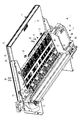
図4は、用紙カセット5を示した裏面斜視図である。図2および図4に示すように、用紙カセット5は、未印刷(未記録)の用紙Pを起立姿勢で収容するカセット本体(媒体カセット)51と、カセット本体51の外面(装置内部側)に設けられ、印刷済み(記録済み)の用紙Pを起立姿勢で且つ保持面61に重ねて保持する排紙保持部(保持部)52と、を備えている。すなわち、カセット本体51から未印刷の用紙Pが供給され、排紙保持部52に印刷済みの用紙Pが排出される。そして、用紙カセット5を装置本体から取り外すことで、カセット本体51と共に、保持した印刷済みの用紙Pを取り出すことができる。また、用紙カセット5を取り外すことで記録装置1の内部が露出させることができ、搬送路Rに用紙Pが詰まった等の不具合を容易に解消することができる。なお、図示は省略するが、用紙カセット5は、筐体2に対してZ軸方向にスライド自在に構成されており、その着脱操作は、用紙カセット5をスライドさせることで行われる。
FIG. 4 is a rear perspective view showing the
カセット本体51は、装着時に筐体2の前面と面一になり(図1参照)、記録装置1の概観をなすカセット筐体部53と、カセット筐体部53側を収容面とし、全体としてトレイ状に形成された本体トレイ54と、本体トレイ54の上部に対面し、用紙Pを収容する用紙収容空間を開閉する上部カバー55と、本体トレイ54の下部に位置し、用紙収容空間に収容した用紙Pの先端を揺動させる可動トレイ59と、を備えている。
The
また、上部カバー55の外面、すなわち、筐体2に装着した際に装置内部側に向く面は、印刷済みの用紙Pを保持する(蓄える)ための保持面61として機能している(詳細は後述する。)。
Further, the outer surface of the
可動トレイ59は、用紙カセット5が装着された状態において用紙送り方向下流側となる本体トレイ54の下側に設けられ、いわゆるホッパーとして機能するものである。可動トレイ59は、本体トレイ54の上下方向略中央部に設けられた左右一対の揺動支点59aを中心に回動可能になっており、図外の駆動機構により揺動するようになっている。これにより、収容された用紙Pの先端を、後述の給送ローラー41に圧接させる状態(図2参照)と、離間させる状態(図示省略)と、にすることができる。
The
図2に示すように、搬送部4は、可動トレイ59の先端部に対向し、収容された用紙Pに転接して引き出すと共に、用紙Pを湾曲反転させて上方に送る大形の給送ローラー41と、給送ローラー41に対向し、反転送りをガイドするガイド部材45および補助従動ローラー46と、給送ローラー41からの用紙Pを印刷部3に送る搬送ローラー42と、印刷部3に対面する案内部材33と、案内部材33の下流側に配設され、用紙Pの上反りを矯正する拍車状のガイドローラー43と、ガイドローラー43の下流側に配設され、用紙Pを排紙保持部52に排紙する排紙ローラー(媒体排出手段)44と、排紙ローラー44の下流側に配設され、用紙Pを排紙保持部52側に押圧する用紙押圧機構47と、を備えている。なお、用紙押圧機構47は、送り出された直後の用紙Pの下端部を、排紙ローラー44近傍から、排紙保持部52の保持面61側に送り込む役割を担っている。
As shown in FIG. 2, the
給送ローラー41は、駆動ローラーで構成されており、カセット本体51から引き出した用紙Pを、外周面に沿って円弧状に搬送する。ガイド部材45は、給送ローラー41の外周面に対面して湾曲形状に形成され、用紙Pを外側からガイドする。補助従動ローラー46は、自由回転ローラーで構成されており、用紙Pを挟んで給送ローラー41に転接して、反転送りを補助する。搬送ローラー42は、前方側の搬送駆動ローラー42aと後方側の搬送従動ローラー42bとを有するニップローラーで構成されており、用紙Pの送り(副走査)を制御するメインローラーとして機能する。なお、給送ローラー41、搬送ローラー42およびガイドローラー43は、それぞれ用紙Pの幅方向(X軸方向)に適宜の間隔で配設された複数個の分割ローラーで構成されている。
The feeding
案内部材33は、搬送路Rの一部を構成すると共に、用紙Pの記録面とインクジェットヘッド32との間のギャップ(ワークギャップ)を規定する(いわゆるプラテンとして機能する)。また、案内部材33には、インクジェットヘッド32と対向する位置に縁無し印刷の際、用紙P端から外れた領域に吐出されるインクを受ける凹部が形成されている。この凹部の中には、インクを吸収するインク吸収材(図示省略)が設けられている。そして更に、案内部材33の下方には、打ち捨てられたインクを貯留する廃液タンク(図示省略)が配置されている。
The
排紙ローラー44は、前方側(保持面61側)の排紙駆動ローラー(駆動ローラー)44aと後方側の排紙従動ローラー44bとを有するニップローラーで構成されており、案内部材33の上側に位置する用紙Pに張力(tension)を付与するテンションローラーとして機能する。また、排紙保持部52の下部近傍に配設され、用紙Pを排紙保持部52の保持面61に沿わせるように送り出す。具体的には、排紙ローラー44による用紙Pの送り出し方向は、用紙カセット5に向かう様に斜め上方に設定されている(図5参照)。そのため、排出される用紙Pは、排紙保持部52の保持面61(後述する。)に摺接しながら上方に移動し、排紙保持部52の保持面61に保持される。
The
排紙駆動ローラー44aは、ゴムローラーにより構成され、排紙従動ローラー44bは、スターホイール(拍車状のローラー)により構成されている。さらに、排紙駆動ローラー44aおよび排紙従動ローラー44bは、それぞれ用紙Pの幅方向(X軸方向)に適宜の間隔で配設された複数個の分割ローラーで構成されている(図3参照)。なお、詳細は後述するが、送り出された直後の用紙Pの下端部に、排紙駆動ローラー44aが下側から転接する。その結果、排紙駆動ローラー44aの外周面に下端部が支持される形で、用紙Pに保持面61側への送り込み力を付与する。これによって、用紙押圧機構47による送り込みを補助している。また、この構成であれば、排紙駆動ローラー44aが用紙Pの印刷面側に直接接触することがないので、印刷面を汚したり、傷つけたりすることも少なくなる。
The paper
給送ローラー41により下方へと引き出された用紙Pは、給送ローラー41、ガイド部材45および補助従動ローラー46によって上向きに反転させられ、搬送ローラー42へと送られる。さらに、用紙Pは、搬送ローラー42の間に挟圧搬送されて、印刷部3に送られる。印刷部3で記録の行われた用紙Pは、ガイドローラー43および排紙ローラー44を介して、用紙カセット5の排紙保持部52に排紙される。
The paper P drawn downward by the feeding
印刷処理では、搬送部4によって用紙Pを略Z軸方向に間欠送り(副走査)すると共に、インクジェットヘッド32を駆動しつつ、キャリッジ移動機構37によって、キャリッジユニット30をX軸方向に往復させて(主走査)、用紙Pに画像データを印刷する。
In the printing process, the paper P is intermittently fed (sub-scanned) in the substantially Z-axis direction by the
次に図4、図5および図6を参照して、排紙保持部52および用紙押圧機構47について詳細に説明する。図5は、排紙保持部52廻りを示した断面図である。図4および図5に示すように、排紙保持部52は、上部カバー55の外面(装置内部側)によって構成された保持面61と、排紙された用紙Pの下端部を受容する受容部62と、保持面61に設けられ、用紙Pを起立姿勢に保持するホルダー63と、を有している。
Next, the paper
保持面61は、用紙カセット5を筐体2に装着した際に、一対の排紙ローラー44の近傍から用紙排出口24までの間に位置する略平坦な面であり、且つ鉛直方向に延在する面である。排紙ローラー44により排出された用紙Pは、保持面61に沿って摺接しながら用紙排出口24に向かって移動する。そして、保持面61に重ねて保持される。また、用紙Pのサイズによっては、用紙排出口24から上方に突出して排紙される。そのため、これを受けるべく、上部カバー55は、上下方向に伸縮自在に可動することが好ましい。
The holding
受容部62は、保持面61から排紙ローラー44側に突出し、用紙Pの下端部を支持する支持部62aと、支持部62aの先端に連なり、排紙駆動ローラー44a側を先上がりにして傾斜した複数の用紙導入部(傾斜部)62bと、を有している。複数の用紙導入部62bは、分割ローラーである排紙駆動ローラー44aの間に入り込むようにして、X軸方向に適宜の間隔で配置されている。つまり、受容部62は、全体として略櫛歯形状に形成されている。また、用紙導入部62bは、用紙押圧機構47により排紙駆動ローラー44aの頂部を越えて保持面61側に送り込まれた用紙Pの下端部を、さらに、保持位置に適切かつ円滑に導く。一方、支持部62aは、保持位置に移動した用紙Pを支持する。このように、一対の排紙ローラー44から送り出された用紙Pは、保持面61および受容部62によって、全体として起立姿勢で重ねて受容(保持)される。
The receiving
図6は、用紙押圧機構47廻りを示した裏面図である。図5および図6に示すように、用紙押圧機構47は、排紙ローラー44によって、送り出される用紙Pを保持面61側に押圧する左右一対の押圧ローラー(媒体押圧手段)81と、装置フレームに支持されると共に、一対の押圧ローラー81を回転自在に支持する一対のローラーフレーム82と、を備えている。なお、一対の押圧ローラー81は、一方の押圧ローラー81が、想定される最小幅の用紙Pを中央で押圧し、一対の押圧ローラー81が、想定される最大幅の用紙Pを、左右バランスよく押圧する位置に配設されている。
FIG. 6 is a rear view showing the periphery of the
各押圧ローラー81は、用紙Pに接触して回転する自由回転ローラーである共に、スターホイール(拍車状のローラー)で構成されている。また、各押圧ローラー81は、送り出された直後の用紙Pの下部に対面する位置に配設され、且つ排紙ローラー44の送り出し方向となる仮想面Sに対し、排紙従動ローラー44b側から排紙駆動ローラー44a側に突出して配設されている。すなわち、押圧ローラー81は、用紙Pの送り出しを許容しつつ、送り出された直後の用紙Pの下部を保持面61側に押圧する構成となっている。この押圧力によって、用紙Pが湾曲状態となり、この湾曲を平坦にしようとする反力が発生する。この反力が用紙P下端部を保持面61側への送り込むための、送り込み力となる。なお、仮想面Sは、排紙駆動ローラー44aの軸心と排紙従動ローラー44bの軸心との結ぶ面に直交し、且つ排紙駆動ローラー44aと排紙従動ローラー44bとのニップ点を通る面である。
Each pressing
図7は、用紙押圧機構47による用紙P下端部の送り込み動作を示した遷移図である。図7に示すように、用紙Pの送り出し最中には、押圧ローラー81の表面(印刷面)に用紙Pに転接し、排紙ローラー44による送り出しを許容しつつ、用紙Pを保持面側に押圧している(図7(a)参照)。そして、用紙Pの送り出し直後には、押圧ローラー81が用紙Pの下部に接触し、保持面61側に押圧する。また、これと共に、排紙駆動ローラー44aを駆動し続け、用紙Pの下端部に下側から転接する(図7(b)参照)。押圧ローラー81の押圧によって、用紙P下端部に送り込み力が付与され、一方、排紙駆動ローラー44aが、用紙P下端部を、その外周面で支持しつつ回転して、用紙P下端部に送り込み力を付与する。これら押圧ローラー81と排紙駆動ローラー44aとの協働によって、用紙P下端部が、排紙ローラー44近傍から、保持面61側に送り込まれる。排紙駆動ローラー44aの頂部を越えた用紙P下端部は、用紙導入部62bに導かれて支持部62aに到達し、用紙Pが保持面61に沿わせる保持される(図7(c)参照)。このような送り込み動作によって、複数枚の用紙Pが適切に重ねて保持される。
FIG. 7 is a transition diagram showing the feeding operation of the lower end portion of the paper P by the
図8は、送り込み精度と、押圧ローラー81の位置および用紙Pの腰の強さと、の関係を示した図である。図8に示すように、用紙Pの送り込み精度には、仮想面Sに対する押圧ローラー81の突出量と、送り出し方向における押圧ローラー81の排紙ローラー44(厳密には、そのニップ点)からの距離と、用紙Pの腰(剛性)の強さと、が大きく関わっている。具体的には、基本的に、突出量が大きいほど、排紙ローラー44からの距離が短いほど、用紙Pの腰が強いほど、送り込み精度が高くなるが、一方で、用紙Pの剛性に伴う弾性限界点を超えるほどに、これらが進行すると、送り込み精度が低くなってしまう。よって、これらを考慮し、想定される用紙Pの剛性に応じて、突出量および排紙ローラー44からの距離を設定し、押圧ローラー81を配設することが好ましい。なお、用紙Pの上端部が押圧ローラー81の後方側に入り込まないように、押圧ローラー81の突出量は、押圧ローラー81の軸心が、仮想面Sを超えない量である必要がある。
FIG. 8 is a diagram showing the relationship between the feeding accuracy and the position of the
以上のような構成によれば、押圧ローラー81により、用紙Pの下端部を、排紙ローラー44の近傍から保持面61側に確実に送り込むことができる。一方、用紙押圧機構47は、突出状態で用紙Pの送り出しを許容する構造を有しているため、用紙押圧機構47を可動式にすることなく用紙Pを重ねて保持でき、簡単な構成で且つ煩雑な制御を必要としない記録装置1を提供することができる。特に記録装置1のように縦置き配置するものであれば、Y軸方向の長さをできるだけ短くした方が設置面積を少なくする上で好ましい。Y軸方向の長さをできるだけ短くするには、排紙ローラー44による用紙Pの送り出し方向である仮想面Sを、用紙Pが用紙カセット5に安定して向かうために斜めにしておく必要はあるが、できるだけZ軸方向と平行になるようにした方がよい。しかし記録装置1の設置面積を少なくするために、仮想面SをZ軸方向に近づけるほど、用紙Pの下端部の送り込みが難しく、排紙ローラー44で用紙Pの下端部が停滞しやすくなる。これは、仮想面SをZ軸方向に近づける、つまり用紙Pを鉛直に近い角度で送り出すことになると、排紙ローラー44のニップ点が、排紙駆動ローラー44aの頂部から極端に低くなってしまうので、ニップ点から外れた用紙Pの下端部に対し、排紙駆動ローラー44aが滑って(摩擦不足)、排紙駆動ローラー44aの頂部を越えることができず、その場に止まってしまうからである。しかしながら本発明であれば用紙Pの保持面61側への送り込みを簡単な構成で確実に実現することが可能となる。
According to the above configuration, the lower end portion of the paper P can be reliably fed from the vicinity of the
また、排紙駆動ローラー44aが、送り出された直後の用紙Pの下端部に転接して、用紙P下端部の送り込みを補助する構成であるため、用紙Pを保持面61側により確実に送り込むことができる。
In addition, since the
さらに、用紙押圧機構47において、用紙Pを押圧する部材(押圧ローラー81)を、自由回転ローラーで構成することにより、用紙押圧機構47による送り出しに抗した摩擦抵抗を低減することができる。そのため、先行する用紙Pに重ねつつ、用紙Pを安定して送り出すことができる。
Furthermore, in the
またさらに、押圧ローラー81をスターホイールで構成することにより、用紙Pへの接触面積を小さくすることができるため、押圧ローラー81へのインクの付着を抑制しつつ、送り出しにおける摩擦抵抗をより低減することができる。
Furthermore, since the contact area to the paper P can be reduced by configuring the
また、押圧ローラー81を左右一対設けることにより、幅方向の2個所で用紙Pを押圧することができるため、幅領域全域で用紙Pを押圧することができる。よって、用紙Pの下端部を保持面61側により確実に送り込むことができる。
In addition, by providing a pair of left and right
さらに、排紙保持部52において、支持部62aおよび用紙導入部62bを設けることにより、支持部62aにより、用紙Pを保持位置で適切に保持することができると共に、用紙導入部62bにより、用紙Pの下部を、保持位置に円滑に導くことができる。また、保持後の用紙Pと排紙ローラー44との接触を有効に防止することができる。
Further, by providing the
またさらに、排紙保持部52を、カセット本体51の外面に形成することにより、排紙保持部52をカセット本体51と一体として取り外すことができるため、寸法の小さい用紙P(葉書等)を保持した際にも、容易に取り出すことができる。
Further, by forming the paper
なお、本実施形態においては、用紙Pを押圧する部材(押圧ローラー81)を、自由回転ローラーで構成したが、これに限るものではなく、排紙ローラー44の送り出しを許容しつつ、用紙Pを保持面61側に押圧可能な部材であれば、これに限るものではない。例えば、円柱形の固定部材や、半円柱形の固定部材、保持面61側を先端とする三角柱形の固定部材であっても良い。すなわち、仮想面Sに対し、保持面61側を先上がりとして傾斜する傾斜面または湾曲面を当接面とする固定部材を用いることも考えられる。
In the present embodiment, the member (pressing roller 81) that presses the paper P is configured by a free rotation roller. However, the invention is not limited thereto, and the paper P can be fed while allowing the
また、本実施形態においては、押圧ローラー81を用紙Pの幅方向(送り出し方向に直交する方向)に並列して2個設ける構成であったが、押圧ローラー81を1個のみ設ける構成であっても良いし、幅方向に並列して3個以上設ける構成であっても良い。
Further, in the present embodiment, the two
なお、本実施形態において、各押圧ローラー81は、各ローラーフレーム82に突出方向に直動付勢あるいは回動付勢されている構成であっても良い。
In the present embodiment, each
1:記録装置、 3:印刷部、 44:排紙ローラー、 44a:排紙駆動ローラー、 51:カセット本体、 52:排紙保持部、 61:保持面、 62a:支持部、 62b:用紙導入部、 81:押圧ローラー、 P:用紙、 S:仮想面
DESCRIPTION OF SYMBOLS 1: Recording apparatus 3: Printing part 44:
Claims (6)
前記画像記録部により記録された前記記録媒体を上方に向って送り出す媒体排出手段と、
前記媒体排出手段により送り出された前記記録媒体を上方に向かう姿勢に保持する保持部と、
前記媒体排出手段の上方に配設され、前記媒体排出手段により送り出された前記記録媒体を前記保持部に向けて押圧する媒体押圧手段と、
を備え、
前記保持部は、上方に延びる面と、前記面の上部側に設けられて前記記録媒体を上方に向かう姿勢に保持するホルダーと、を有し、
前記媒体押圧手段は、装置本体に軸支され、前記媒体排出手段によって送り出された前記記録媒体に接触して自由に回転する自由回転ローラーを有し、
前記自由回転ローラーは、前記媒体排出手段による前記記録媒体の送り出し方向となる仮想面に対して前記保持部側に突出した状態で配設されるとともに、軸心が前記仮想面に対して前記保持部側とは反対側に軸支され、前記媒体排出手段により送り出された前記記録媒体を前記保持部に向けて押圧する、
ことを特徴とする記録装置。 An image recording unit for recording an image on a recording medium;
Medium discharge means for feeding the recording medium recorded by the image recording unit upward;
A holding unit for holding the recording medium sent out by the medium discharging unit in an upward direction;
Medium pressing means disposed above the medium discharging means and pressing the recording medium sent out by the medium discharging means toward the holding portion;
With
The holding portion has a surface extending upward, and a holder provided on the upper side of the surface to hold the recording medium in an upward posture.
The medium pressing means has a free rotating roller that is pivotally supported by the apparatus main body and freely rotates in contact with the recording medium fed by the medium discharging means,
The free rotating roller is disposed in a state of projecting toward the holding portion with respect to a virtual surface that is a feeding direction of the recording medium by the medium discharging means, and an axis is held with respect to the virtual surface. Is supported on the side opposite to the part side, and presses the recording medium sent out by the medium discharging means toward the holding part,
A recording apparatus.
前記自由回転ローラーは、スターホイールで構成されている、
ことを特徴とする記録装置。 The recording apparatus according to claim 1,
The free rotating roller is composed of a star wheel,
A recording apparatus.
前記送り出し方向に直交する方向に、前記自由回転ローラーが複数配設されている、
ことを特徴とする記録装置。 The recording apparatus according to claim 1 or 2, wherein
A plurality of the free rotating rollers are arranged in a direction perpendicular to the feeding direction,
A recording apparatus.
前記媒体排出手段は、前記保持部側に駆動ローラーを配置したニップローラーを有している、
ことを特徴とする記録装置。 The recording apparatus according to any one of claims 1 to 3, wherein
The medium discharging means has a nip roller having a driving roller disposed on the holding part side,
A recording apparatus.
前記保持部は、
前記媒体押圧手段の押圧により、下部が前記保持部側に移動した前記記録媒体を、さらに保持位置に導く傾斜部と、
前記傾斜部に連なり、前記保持位置に移動した前記記録媒体を下側から支持する支持部と、を有している、
ことを特徴とする記録装置。 The recording apparatus according to any one of claims 1 to 4, wherein
The holding part is
An inclined portion that further guides the recording medium whose lower portion has moved to the holding portion side by pressing of the medium pressing means to a holding position;
A support portion that is connected to the inclined portion and supports the recording medium moved to the holding position from below.
A recording apparatus.
前記画像記録部により記録を行う前の前記記録媒体を下方に向かう姿勢で収容すると共に着脱自在に構成された媒体カセットを、更に備え、
前記保持部は、前記媒体カセットに形成されている、
ことを特徴とする記録装置。 The recording apparatus according to any one of claims 1 to 5,
A medium cassette configured to detachably store the recording medium before being recorded by the image recording unit in a downward direction; and
The holding portion is formed on the medium cassette.
A recording apparatus.
Priority Applications (3)
| Application Number | Priority Date | Filing Date | Title |
|---|---|---|---|
| JP2011026867A JP5876655B2 (en) | 2011-02-10 | 2011-02-10 | Recording device |
| US13/365,694 US8528897B2 (en) | 2011-02-10 | 2012-02-03 | Recording apparatus |
| CN201210030417.3A CN102632724B (en) | 2011-02-10 | 2012-02-10 | Tape deck |
Applications Claiming Priority (1)
| Application Number | Priority Date | Filing Date | Title |
|---|---|---|---|
| JP2011026867A JP5876655B2 (en) | 2011-02-10 | 2011-02-10 | Recording device |
Publications (3)
| Publication Number | Publication Date |
|---|---|
| JP2012166359A JP2012166359A (en) | 2012-09-06 |
| JP2012166359A5 JP2012166359A5 (en) | 2014-02-13 |
| JP5876655B2 true JP5876655B2 (en) | 2016-03-02 |
Family
ID=46971015
Family Applications (1)
| Application Number | Title | Priority Date | Filing Date |
|---|---|---|---|
| JP2011026867A Active JP5876655B2 (en) | 2011-02-10 | 2011-02-10 | Recording device |
Country Status (1)
| Country | Link |
|---|---|
| JP (1) | JP5876655B2 (en) |
Family Cites Families (5)
| Publication number | Priority date | Publication date | Assignee | Title |
|---|---|---|---|---|
| JP2605710B2 (en) * | 1987-04-07 | 1997-04-30 | セイコーエプソン株式会社 | Inkjet printer |
| JP3281463B2 (en) * | 1993-10-19 | 2002-05-13 | ブラザー工業株式会社 | Paper feed / discharge device in image forming apparatus |
| JPH08169616A (en) * | 1994-12-15 | 1996-07-02 | Citizen Watch Co Ltd | Storing device for ink jut printer discharge recording sheet |
| JPH11147642A (en) * | 1997-11-18 | 1999-06-02 | Canon Inc | Sheet material support and image forming device |
| JP5038467B2 (en) * | 2010-06-10 | 2012-10-03 | 東芝テック株式会社 | Printer |
-
2011
- 2011-02-10 JP JP2011026867A patent/JP5876655B2/en active Active
Also Published As
| Publication number | Publication date |
|---|---|
| JP2012166359A (en) | 2012-09-06 |
Similar Documents
| Publication | Publication Date | Title |
|---|---|---|
| JP2014156088A (en) | Transport device and image recording apparatus | |
| JP2011156736A (en) | Image recorder | |
| JP5673126B2 (en) | Image recording device | |
| JP5876655B2 (en) | Recording device | |
| US8528897B2 (en) | Recording apparatus | |
| CN113291058A (en) | Printing device | |
| JP4065857B2 (en) | Inkjet recording device | |
| JP2007245599A (en) | Medium carrier, liquid injection apparatus and recorder | |
| JP2012030452A (en) | Inkjet printer | |
| JP5728989B2 (en) | Recording device | |
| US20120193864A1 (en) | Recording Apparatus | |
| JP6288422B2 (en) | Recording device | |
| JP2012166360A (en) | Recording apparatus | |
| JP6119539B2 (en) | Inkjet recording device | |
| JP2012192548A (en) | Recording apparatus | |
| JP2013112459A (en) | Image recorder | |
| JP4433161B2 (en) | Inkjet recording device | |
| JP5894730B2 (en) | Recording device | |
| JP5724276B2 (en) | Recording device | |
| JP6065082B2 (en) | Recording device | |
| JP5772056B2 (en) | Medium transport mechanism and recording apparatus provided with the same | |
| JP2023095336A (en) | Sheet feeder and recording device | |
| JP5776211B2 (en) | Recording media cassette | |
| JP2012076397A (en) | Recording device | |
| JP2012162060A (en) | Recording apparatus |
Legal Events
| Date | Code | Title | Description |
|---|---|---|---|
| A521 | Written amendment |
Free format text: JAPANESE INTERMEDIATE CODE: A523 Effective date: 20131225 |
|
| A621 | Written request for application examination |
Free format text: JAPANESE INTERMEDIATE CODE: A621 Effective date: 20131225 |
|
| A977 | Report on retrieval |
Free format text: JAPANESE INTERMEDIATE CODE: A971007 Effective date: 20140811 |
|
| A131 | Notification of reasons for refusal |
Free format text: JAPANESE INTERMEDIATE CODE: A131 Effective date: 20140819 |
|
| A521 | Written amendment |
Free format text: JAPANESE INTERMEDIATE CODE: A523 Effective date: 20141014 |
|
| A02 | Decision of refusal |
Free format text: JAPANESE INTERMEDIATE CODE: A02 Effective date: 20141104 |
|
| RD04 | Notification of resignation of power of attorney |
Free format text: JAPANESE INTERMEDIATE CODE: A7424 Effective date: 20150106 |
|
| A521 | Written amendment |
Free format text: JAPANESE INTERMEDIATE CODE: A523 Effective date: 20150130 |
|
| A911 | Transfer of reconsideration by examiner before appeal (zenchi) |
Free format text: JAPANESE INTERMEDIATE CODE: A911 Effective date: 20150206 |
|
| A912 | Removal of reconsideration by examiner before appeal (zenchi) |
Free format text: JAPANESE INTERMEDIATE CODE: A912 Effective date: 20150227 |
|
| A521 | Written amendment |
Free format text: JAPANESE INTERMEDIATE CODE: A523 Effective date: 20151124 |
|
| A61 | First payment of annual fees (during grant procedure) |
Free format text: JAPANESE INTERMEDIATE CODE: A61 Effective date: 20160122 |
|
| R150 | Certificate of patent (=grant) or registration of utility model |
Ref document number: 5876655 Country of ref document: JP Free format text: JAPANESE INTERMEDIATE CODE: R150 |
|
| S531 | Written request for registration of change of domicile |
Free format text: JAPANESE INTERMEDIATE CODE: R313531 |
|
| R350 | Written notification of registration of transfer |
Free format text: JAPANESE INTERMEDIATE CODE: R350 |