JP5847014B2 - Head-mounted display device - Google Patents
Head-mounted display device Download PDFInfo
- Publication number
- JP5847014B2 JP5847014B2 JP2012113341A JP2012113341A JP5847014B2 JP 5847014 B2 JP5847014 B2 JP 5847014B2 JP 2012113341 A JP2012113341 A JP 2012113341A JP 2012113341 A JP2012113341 A JP 2012113341A JP 5847014 B2 JP5847014 B2 JP 5847014B2
- Authority
- JP
- Japan
- Prior art keywords
- head
- unit
- battery
- display device
- display unit
- Prior art date
- Legal status (The legal status is an assumption and is not a legal conclusion. Google has not performed a legal analysis and makes no representation as to the accuracy of the status listed.)
- Expired - Fee Related
Links
- 230000005484 gravity Effects 0.000 claims description 24
- 210000003128 head Anatomy 0.000 description 42
- 230000003287 optical effect Effects 0.000 description 10
- 239000011521 glass Substances 0.000 description 9
- 238000004891 communication Methods 0.000 description 6
- 210000001747 pupil Anatomy 0.000 description 4
- 230000000694 effects Effects 0.000 description 3
- 238000005286 illumination Methods 0.000 description 3
- 238000013459 approach Methods 0.000 description 2
- 230000008878 coupling Effects 0.000 description 2
- 238000010168 coupling process Methods 0.000 description 2
- 238000005859 coupling reaction Methods 0.000 description 2
- 238000010586 diagram Methods 0.000 description 2
- 230000013011 mating Effects 0.000 description 2
- 239000000758 substrate Substances 0.000 description 2
- 238000007792 addition Methods 0.000 description 1
- 238000012217 deletion Methods 0.000 description 1
- 230000037430 deletion Effects 0.000 description 1
- 230000002349 favourable effect Effects 0.000 description 1
- 238000012423 maintenance Methods 0.000 description 1
- 230000002093 peripheral effect Effects 0.000 description 1
Images


Classifications
-
- G—PHYSICS
- G02—OPTICS
- G02B—OPTICAL ELEMENTS, SYSTEMS OR APPARATUS
- G02B27/00—Optical systems or apparatus not provided for by any of the groups G02B1/00 - G02B26/00, G02B30/00
- G02B27/01—Head-up displays
- G02B27/017—Head mounted
- G02B27/0172—Head mounted characterised by optical features
-
- G—PHYSICS
- G02—OPTICS
- G02B—OPTICAL ELEMENTS, SYSTEMS OR APPARATUS
- G02B27/00—Optical systems or apparatus not provided for by any of the groups G02B1/00 - G02B26/00, G02B30/00
- G02B27/01—Head-up displays
- G02B27/017—Head mounted
- G02B27/0176—Head mounted characterised by mechanical features
-
- G—PHYSICS
- G02—OPTICS
- G02B—OPTICAL ELEMENTS, SYSTEMS OR APPARATUS
- G02B27/00—Optical systems or apparatus not provided for by any of the groups G02B1/00 - G02B26/00, G02B30/00
- G02B27/01—Head-up displays
- G02B27/017—Head mounted
-
- G—PHYSICS
- G02—OPTICS
- G02B—OPTICAL ELEMENTS, SYSTEMS OR APPARATUS
- G02B27/00—Optical systems or apparatus not provided for by any of the groups G02B1/00 - G02B26/00, G02B30/00
- G02B27/01—Head-up displays
- G02B27/0149—Head-up displays characterised by mechanical features
- G02B2027/0152—Head-up displays characterised by mechanical features involving arrangement aiming to get lighter or better balanced devices
-
- G—PHYSICS
- G02—OPTICS
- G02B—OPTICAL ELEMENTS, SYSTEMS OR APPARATUS
- G02B27/00—Optical systems or apparatus not provided for by any of the groups G02B1/00 - G02B26/00, G02B30/00
- G02B27/01—Head-up displays
- G02B27/017—Head mounted
- G02B2027/0178—Eyeglass type
Landscapes
- Physics & Mathematics (AREA)
- General Physics & Mathematics (AREA)
- Optics & Photonics (AREA)
- Eyeglasses (AREA)
Description
本発明は、頭部装着型表示装置に関するものである。 The present invention relates to a head-mounted display device.
近年、頭部装着型表示装置として、頭部の片側に装着し、片目に対してのみ画像や映像の表示を行うものがある。 In recent years, there is a head-mounted display device that is mounted on one side of the head and displays an image or video only to one eye.
このような頭部装着型表示装置として、頭部に装着可能な眼鏡フレームに取り付ける構成が開示されている(特許文献1〜4参照。)。このような構成においては、いずれも、表示ユニットは、眼鏡フレームのテンプル(ツル)に固定し、表示ユニットをレンズの前方に配置している。
As such a head-mounted display device, a configuration for mounting on a spectacle frame that can be mounted on the head is disclosed (see
しかしながら、頭部装着型表示装置を眼鏡フレームに取り付ける場合、頭部装着型表示装置の重量が眼鏡フレームの片側のテンプルにかかるため、使用者が装着した眼鏡が傾いてしまうことがある。
また、使用者の瞳に向けて映像を映し出す表示ユニットは眼鏡のレンズの前方に配置されているため、頭部装着型表示装置を装着した眼鏡は重心が前方に集中し、眼鏡が鼻からずり落ちてしまいやすくなる。
このように、これまでの頭部装着型表示装置は、重量バランスが悪く、使用者にとっては、装着感が良くないという問題がある。
However, when the head-mounted display device is attached to the spectacle frame, the weight of the head-mounted display device is applied to the temple on one side of the spectacle frame, and the spectacles worn by the user may be tilted.
In addition, the display unit that projects the image toward the user's pupil is located in front of the eyeglass lens, so the center of gravity of the eyeglasses equipped with a head-mounted display device is concentrated forward, and the eyeglasses are displaced from the nose. It tends to fall.
As described above, the conventional head-mounted display devices have a problem that the weight balance is poor and the feeling of wearing is not good for the user.
また、近年、頭部装着型表示装置を、無線を介して映像信号等を受信することによってワイヤレスとしたものもある。この場合、頭部装着型表示装置には、無線通信回路や、電源を確保するためにバッテリを搭載する。特に、バッテリは、頭部装着型表示装置を構成する他の部品に比較すると重量が大きいために、上記したような重量バランスに与える影響が大きく、上記問題は顕著なものとなってしまう。 In recent years, some head-mounted display devices are made wireless by receiving video signals or the like via radio. In this case, the head-mounted display device is equipped with a wireless communication circuit and a battery for securing a power source. In particular, since the battery is heavier than other components constituting the head-mounted display device, the battery has a large influence on the weight balance as described above, and the above problem becomes remarkable.
本発明は、このような事情に鑑みてなされたものであって、重量バランスを改善し、使用者の装着感を向上させることのできる頭部装着型表示装置を提供することを目的とする。 The present invention has been made in view of such circumstances, and an object of the present invention is to provide a head-mounted display device that can improve a weight balance and improve a user's wearing feeling.
上記課題を解決するために、本発明は以下の手段を採用する。
本発明の一態様は、表示素子を有する表示ユニットと、前記表示ユニットを制御する回路基板と、前記回路基板および前記表示ユニットに電力を供給するバッテリ部と、これらを使用者の頭部に支持させる支持部とを備え、前記バッテリ部が、前記支持部による支持位置を挟み、前記表示ユニットとは反対側に配置され、使用者の頭部に装着した状態で、頭部に接近する側に傾いて配置されている頭部装着型表示装置を提供する。
これにより、使用者の頭部により支持される支持部の支持位置の一方の側に位置する表示ユニットに対し、他方の側に位置するバッテリ部がカウンタバランスとして機能し、頭部装着型表示装置の前後方向のバランスを改善することができる。また、平面視した状態での頭部装着型表示装置の重心位置を頭部に接近させることができ、重量バランスをさらに改善することができる。
In order to solve the above problems, the present invention employs the following means.
One embodiment of the present invention includes a display unit having a display element, a circuit board that controls the display unit, a battery unit that supplies power to the circuit board and the display unit, and supports these on the user's head And the battery unit is disposed on the opposite side of the display unit with the support position by the support unit interposed therebetween, and is attached to the user's head, on the side approaching the head. Provided is a head-mounted display device that is disposed at an angle .
Thereby, the battery unit located on the other side functions as a counter balance with respect to the display unit located on one side of the support position of the support portion supported by the user's head, and the head-mounted display device The balance in the front-rear direction can be improved. Further, the center of gravity of the head-mounted display device in a plan view can be brought closer to the head, and the weight balance can be further improved.
上記態様においては、前記支持部による支持位置から前記バッテリ部までの長さよりも、前記支持部による支持位置から前記表示ユニットまでの長さの方が長くなるよう配置されていてもよい。
支持位置もしくは装置全体の重心位置が後方に配置されることで、眼鏡フレームの前方にかかる重量を軽減することができる。
In the said aspect, you may arrange | position so that the length from the support position by the said support part to the said display unit may become longer than the length from the support position by the said support part to the said battery part.
Since the support position or the center of gravity position of the entire apparatus is disposed rearward, the weight applied to the front of the spectacle frame can be reduced.
上記態様においては、前記支持部が、使用者の頭部または使用者の頭部に装着された眼鏡のテンプルへの取付部であり、該取付部が、前記表示ユニットと前記バッテリ部とを結ぶ前後方向における重心位置の近傍に配置されていてもよい。
頭部装着型表示装置の重心が、使用者の頭部または眼鏡のテンプルへの取付部近傍となることで、頭部装着型表示装置の前後方向のバランスが特に優れたものとなる。
In the above aspect, the support part is a user's head or an attachment part to a temple of a spectacle attached to the user's head, and the attachment part connects the display unit and the battery part. You may arrange | position in the vicinity of the gravity center position in the front-back direction.
Since the center of gravity of the head-mounted display device is in the vicinity of the attachment portion of the user's head or glasses to the temple, the balance in the front-rear direction of the head-mounted display device is particularly excellent.
上記態様においては、前記回路基板が、前記表示ユニットと前記バッテリ部との間に設けられていてもよい。
これにより、表示ユニットに回路基板を一体に備える構成に比較し、表示ユニットを軽量化することができ、頭部装着型表示装置の前端部への荷重集中を回避することができる。
In the above aspect, the circuit board may be provided between the display unit and the battery unit.
Accordingly, the display unit can be reduced in weight as compared with a configuration in which the circuit board is integrally provided in the display unit, and load concentration on the front end portion of the head-mounted display device can be avoided.
上記態様においては、前記回路基板が、使用者の頭部により支持される前記支持位置の近傍に設けられていることが好ましい。
これにより、頭部装着型表示装置の重量バランスを良好に保てる。
In the said aspect, it is preferable that the said circuit board is provided in the vicinity of the said support position supported by a user's head.
Thereby, the weight balance of the head-mounted display device can be kept good.
上記態様においては、前記バッテリ部が、前記表示ユニットと前記バッテリ部とを結ぶ前後方向における重心位置よりも後方に配置されることが好ましい。
これにより、頭部装着型表示装置の重量バランスを良好に保てる。
In the said aspect, it is preferable that the said battery part is arrange | positioned back rather than the gravity center position in the front-back direction which connects the said display unit and the said battery part.
Thereby, the weight balance of the head-mounted display device can be kept good.
上記態様においては、前記表示ユニットと前記バッテリ部とを結ぶ前後方向における重心位置から前記バッテリ部の重心位置までの長さよりも、前記表示ユニットと前記バッテリ部とを結ぶ前後方向における重心位置から前記表示ユニットの重心位置までの長さの方が長くなるよう配置されていることが好ましい。
これにより、支持位置もしくは装置全体の重心位置が後方に配置されることで、眼鏡フレームの前方にかかる重量を軽減することができる。
In the above aspect, rather than the length from the center of gravity in the front-rear direction connecting the display unit and the battery unit to the center of gravity of the battery unit, the center of gravity in the front-rear direction connecting the display unit and the battery unit is It is preferable that the display unit is arranged so that the length to the center of gravity is longer.
Thereby, the weight applied to the front of the spectacle frame can be reduced by arranging the support position or the center of gravity of the entire apparatus behind.
上記態様においては、前記バッテリ部が、前記表示ユニットと前記バッテリ部とを結ぶ前後方向における重心位置よりも後方位置にて着脱可能であってもよい。 In the said aspect, the said battery part may be detachable in the back position rather than the gravity center position in the front-back direction which connects the said display unit and the said battery part.
上記態様においては、前記バッテリ部は、その長手方向が、前記表示ユニットと前記バッテリ部を結ぶ方向に沿うよう配置されていてもよい。
これによって、頭部装着型表示装置の重心位置を中心とした、バッテリ部によるモーメントを大きくすることができ、頭部装着型表示装置の前後方向のバランスを取りやすくなる。
In the said aspect, the said battery part may be arrange | positioned so that the longitudinal direction may follow the direction which connects the said display unit and the said battery part.
This makes it possible to increase the moment due to the battery unit around the center of gravity of the head-mounted display device, making it easier to balance the head-mounted display device in the front-rear direction.
本発明の他の態様においては、表示素子を有する表示ユニットと、前記表示ユニットを制御する回路基板と、前記回路基板および前記表示ユニットに電力を供給するバッテリ部と、これらを使用者の頭部に支持させる支持部とを備え、前記バッテリ部は、前記支持部による支持位置を挟み、前記表示ユニットとは反対側に配置され、使用者の頭部に装着した状態で、頭部に接近する側に傾動可能に設けられていてもよい。これにより、使用者の頭部の大きさや髪型等に応じ、バッテリ部の角度を調整することが可能となる。 In another aspect of the present invention, a display unit having a display element, a circuit board that controls the display unit, a battery unit that supplies electric power to the circuit board and the display unit, and a user's head The battery unit is disposed on the opposite side of the display unit with the support position by the support unit interposed therebetween, and approaches the head while being mounted on the user's head. It may be provided to be tiltable to the side. Thereby, the angle of the battery unit can be adjusted according to the size of the user's head, the hairstyle, and the like.
本発明によれば、頭部装着型表示装置の重量バランスを改善し、使用者の装着感を向上させるという効果を奏することができる。 ADVANTAGE OF THE INVENTION According to this invention, there can exist an effect of improving the weight balance of a head mounting type display apparatus and improving a user's wearing feeling.
以下に、本発明に係る頭部装着型表示装置の一実施形態について、図面を参照して説明する。
〔第1実施形態〕
以下、本発明の第1実施形態について、図1〜図3を用いて説明する。
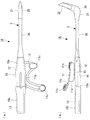
図1は、頭部装着型表示装置1Aの外観を示す平面図および側面図であり、図2は、頭部装着型表示装置1Aの部品レイアウト構成を示すブロック図、図3は、頭部装着型法事装置1Aを眼鏡100のテンプルに装着した状態を示す平面図である。
図1に示すように、頭部装着型表示装置1Aは、表示ユニット21と、表示ユニット21を支持し、使用者の頭部に装着されるホルダ5と、を有する。
Hereinafter, an embodiment of a head-mounted display device according to the present invention will be described with reference to the drawings.
[First Embodiment]
Hereinafter, a first embodiment of the present invention will be described with reference to FIGS.
FIG. 1 is a plan view and a side view showing the appearance of the head-mounted
As shown in FIG. 1, the head-mounted
ホルダ5は、使用者の頭部(例えば耳)に係止するための頭部支持部材(支持部)11を有した第一の筐体10と、表示ユニット21が設けられた第二の筐体20と、第一の筐体10と第二の筐体20とを連結する連結支持部30と、を有している。
The
第一の筐体10は、連結支持部30側に位置する電装部10aと、電装部10aに連続し、ほぼ一定の断面積を有したバッテリ部10bと、を有している。
The
図1、図2に示すように、電装部10aには、外部からブルートゥース、Wi−Fi等の無線通信を介して送信される信号を受信する無線通信回路12a、表示ユニット21を駆動する信号を生成・出力する駆動回路12bおよび制御回路12c等を含む電子基板12が収容されている。また、バッテリ部10bには、電子基板12に電力を供給するバッテリ13が収容されている。
As shown in FIG. 1 and FIG. 2, a signal for driving a
図1に示したように、頭部支持部材11は、第一の筐体10との間に使用者が装着した眼鏡のテンプル部を挟み込むクランプ部11aと、使用者の頭部、例えば使用者の耳に係止可能なフック11bと、耳の前後で頭部に突き当たるパッド11cと、を備えている。
クランプ部11aは、クランプ部11aよりも断面積の小さな連結部(支持位置)15を介して第一の筐体10の電装部10aの外周面に取り付けられている。
As shown in FIG. 1, the
The
図3に示すように、このような頭部支持部材11では、クランプ部11aと第一の筐体10との間に眼鏡100のテンプル101を押し当てると、連結部15が弾性変形することによって、クランプ部11aと第一の筐体10との隙間が拡がり、テンプル101がこの隙間に挿入される。そして、クランプ部11aと第一の筐体10との間でテンプル101を挟み込むことで、頭部装着型表示装置1Aが眼鏡100のテンプル101に支持される。なお、頭部支持部材11の細部の形状や構成については、上記したものに何ら限るものではない。
As shown in FIG. 3, in such a
このようにして、頭部支持部材11が第一の筐体10の電装部10aに設けられ、重量の大きなバッテリ13は、第二の筐体20とは頭部支持部材11を挟んで反対側に位置する第一の筐体10のバッテリ部10bに設けられている。
In this way, the
第二の筐体20は、連結支持部30側の端部からその断面積が漸次増大し、その反対側の端部に、表示ユニット21を構成する接眼光学系22が設けられている。
この接眼光学系22は、連結支持部30および第二の筐体20が延びる方向に対し、使用者が頭部装着型表示装置1Aを頭部に装着した状態で、使用者の視界の範囲内に位置するよう設けられている。
The cross-sectional area of the
The eyepiece
図2に示すように、第二の筐体20は、表示ユニット21を構成するLCD等の表示素子23、照明系24を内蔵している。
As shown in FIG. 2, the
図1に示すように、連結支持部30は、第一の筐体10側から第二の筐体20側に向けて、ほぼ一定の外径を有した棒状をなしている。なお、この連結支持部30は、第一の筐体10側の端部において、第一の筐体10に対して着脱可能とすることができる。
また、図2に示すように、この連結支持部30には、第一の筐体10内の電子基板12と第二の筐体20内の表示素子23とを電気的に接続する配線32が内蔵されている。
As shown in FIG. 1, the
In addition, as shown in FIG. 2, the
この連結支持部30は、使用者が手で自在に曲げることのできる柔軟性と、手を離せば、そのままの形状を維持できる形状維持性と、を有したものとするのが好ましい。これにより、使用者が連結支持部30を曲げることによって、第一の筐体10に対する第二の筐体20の位置や向きを適宜調整できる。具体的には、接眼光学系22の光軸の使用者の瞳への位置合わせ、使用者の瞳に対する接眼光学系22の光軸角度を変えることによる、使用者の視界における表示画面位置の変更、不使用時に使用者の視界の邪魔にならない位置への接眼光学系22の退避、等のために、第二の筐体20の位置や向きを調整する。
The
そして、頭部装着型表示装置1Aは、全体として、連結部15からバッテリ部10bまでの長さよりも、連結部15から表示ユニット21までの長さの方が長くなるように構成されると共に、表示ユニット21とバッテリ部10bとを結ぶ前後方向における重心位置からバッテリ部10bの重心位置までの長さよりも、表示ユニット21とバッテリ部10bとを結ぶ前後方向における重心位置から表示ユニット21の重心位置までの長さの方が長くなるように構成されている。
The head-mounted
このような頭部装着型表示装置1Aにおいては、外部の、例えばパーソナルコンピュータ装置、テレビジョン、HDD(Hard disk drive)やDVD(Digital Versatile Disc)等を用いた映像再生装置等から、無線を介して送信される映像(画像を含む)信号を、第一の筐体10内に設けられた電子基板12の無線通信回路12aで受信する。無線通信回路12aで受信した映像信号は、駆動回路12bにおいて、表示ユニット21の表示素子23を駆動するための駆動信号に変換される。このようにして駆動回路12bで生成された駆動信号は、連結支持部30の配線を介して第二の筐体20の表示ユニット21に伝送される。
表示ユニット21においては、伝送された駆動信号により表示素子23が駆動され、表示素子23は、駆動信号に応じた映像を表示する。表示素子23に表示された映像は、照明系24で発する光により、接眼光学系22に導かれ、接眼光学系22では、導かれた映像を拡大して使用者の瞳に導光し、これによって使用者は、その拡大虚像を視認することができる。
In such a head-mounted
In the
上述したような頭部装着型表示装置1Aによれば、頭部支持部材11が第一の筐体10の電装部10aに設けられ、重量の大きなバッテリ13は、第二の筐体20とは連結部15を挟んで反対側に位置する第一の筐体10のバッテリ部10bに設けられている。これによって、バッテリ13を、表示ユニット21のカウンタバランスとすることができ、頭部装着型表示装置1Aの前後方向における重心位置を、頭部支持部材11の連結部15近傍に位置させることが可能となる。その結果、表示ユニット21とバッテリ13との重量バランスを良好なものとし、頭部装着型表示装置1Aを使用者が装着したときに眼鏡100の前端部に頭部装着型表示装置1Aの重量が集中するのを防ぐ。また、眼鏡100の左右方向においても、頭部装着型表示装置1Aの重心位置を連結部15の近傍に設定することで、頭部装着型表示装置1Aの重量のほとんどを、使用者の耳によって支持することができるので、その重量によって眼鏡100が傾くのを防ぐことができる。
このようにして、使用者が、上記頭部装着型表示装置1Aを眼鏡100に取り付けて頭部に装着したときの装着感、使用感を優れたものとすることができる。
According to the head-mounted
In this way, it is possible to improve the feeling of wearing and usability when the user attaches the head-mounted
また、第一の筐体10に駆動回路12b、制御回路12cを内蔵することにより、第二の筐体20の重量を抑えることができる。これによって、頭部装着型表示装置1Aの重心位置を、頭部支持部材11の近傍に、より一層集中させやすく、上記効果をより確実に得ることができる。
Further, by incorporating the
さて、上記第1実施形態において、頭部装着型表示装置1Aの構成を例示したが、上記に例示したもの以外にも、以下に示す複数例のような構成とすることもできる。なお、以下の説明において、頭部装着型表示装置1Aの全体構成については、上記第1実施形態と同様であり、細部の構成が異なるのみであるので、上記第1実施形態と共通する構成については同符号を付してその説明を省略する。
In the first embodiment, the configuration of the head-mounted
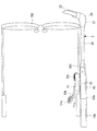
〔第2実施形態〕
図4に示すように、本実施形態における頭部装着型表示装置1Bは、第一の筐体10のバッテリ部10bが、電装部10aおよび連結支持部30の中心軸Cに対し、使用者がこの頭部装着型表示装置1を装着した状態で使用者の頭部に近い側(電装部10aに頭部支持部材11が設けられている側)に傾斜して設けられている。
[Second Embodiment]
As shown in FIG. 4, in the head-mounted
このような構成とすることで、頭部装着型表示装置1Bの重心位置を、平面視した状態で、使用者の頭部に近い位置に設定することができ、より一層安定した装着感を得ることができる。
By setting it as such a structure, the gravity center position of the head mounted
さらに、第一の筐体10に対し、連結部15を前後方向(第一の筐体10と第二の筐体20とを結ぶ方向)に沿ってスライド可能とすることもできる。これには、第一の筐体10に前後方向に延びる溝を形成し、連結部15を、この溝に沿ってスライド移動可能とすれば良い。
このようにすると、使用者の頭部のサイズに応じて、表示ユニット21の前後方向の位置調整を行うことができる。
Further, the connecting
In this way, the position of the
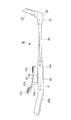
〔第3実施形態〕
図5に示すように、本実施形態における頭部装着型表示装置1Cは、第一の筐体10のバッテリ部10bが、電装部10aに対し、頭部支持部材11が設けられた側の側面に設けられたヒンジ16を介し、使用者の頭部に接近する方向に傾動可能に連結されている。
なお、ヒンジ16の部分においては、バッテリ部10bのバッテリ13と電装部10aの電子基板12とが、図示しない配線により電気的に接続されている。
[Third Embodiment]
As shown in FIG. 5, in the head-mounted
In addition, in the part of the
このような構成によれば、使用者の頭部サイズは髪型等に応じて、バッテリ部10bの角度を適宜変更することができ、可能な範囲内でバッテリ部10bを使用者の頭部側に接近させて、重量バランスを良好なものとすることができる。
According to such a configuration, the user's head size can appropriately change the angle of the
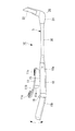
〔第4実施形態〕
図6に示すように、本実施形態における頭部装着型表示装置1Dは、第一の筐体10のバッテリ部10bが、電装部10aに対し、着脱可能とされている。ここで、バッテリ部10bと電装部10aとの接続部19は、連結部15よりも後方(バッテリ部10b側)とするのが好ましい。
[Fourth Embodiment]
As shown in FIG. 6, in the head-mounted
そして、バッテリ部10bは、バッテリ13とともに一体化されてバッテリユニットとすることもできる。そして、バッテリ部10bと電装部10aが、その接続部19に設けられたコネクタ14a、14bにより、互いに機械的および電気的に接続することができる。
The
また、バッテリ部10bと電装部10aは、接続部19において互いに噛み合う同一断面形状とされ、その合わせ面における防水性を確保できるようになっている。
Moreover, the
このような構成においては、上記第1、第2実施形態と同様の作用効果が得られるのに加え、バッテリ部10bのみを着脱できるので、バッテリ部10bのバッテリ13を適宜取り外して充電することができる。また、不使用時には、バッテリ部10bを取り外すことで、コンパクトに収容することもできる。
さらに、予備のバッテリ部10bや、より大容量のバッテリ部10bと交換することもできる。
後者の、大容量のバッテリ部10bと交換する場合、大容量のバッテリ部10bの重量が大きくなるのであれば、上記第2実施形態で示した連結部15のスライド構造を採用し、頭部装着型表示装置1Cの重心位置を前後方向に調整できるようにするのが好ましい。
In such a configuration, in addition to the same effects as those of the first and second embodiments, only the
Further, it can be replaced with a
When the latter is replaced with a large-
〔第5実施形態〕
図7に示すように、本実施形態における頭部装着型表示装置1Eは、第一の筐体10のバッテリ部10bが、電装部10aに対し、ヒンジ17を介して回動可能とされ、バッテリ部10bに収容されるバッテリ13を、バッテリ部10bに対して挿抜できるようになっている。なお、本実施形態においては、ヒンジ17によるバッテリ部10bの回動方向はいかなる方向であっても良い。
このとき、バッテリ13と、電装部10a側の端面には、それぞれ電極18a、18bが設けられ、バッテリ部10bを閉じたときに、双方が接触して電気的に導通されるようになっている。
また、バッテリ部10bと電装部10aは、その接続部において互いに噛み合う同一断面形状とされ、その合わせ面における防水性を確保できるようになっている。
[Fifth Embodiment]
As shown in FIG. 7, in the head-mounted
At this time,
Moreover, the
これにより、バッテリ部10bを開くことで、バッテリ13を適宜着脱したり交換したりできるようになっている。
Thereby, by opening the
なお、上記各実施形態で示した構成以外にも、本発明の主旨を逸脱しない範囲内であれば、適宜の変更、構成の追加・削除を行うことができる。
例えば、頭部装着型表示装置1A〜1Eにおいて、側面視したときに、バッテリ部10bは、電装部10aや連結支持部30の長手方向とほぼ同じ方向に延びるよう設ける構成としたが、バッテリ部10bは、例えば電装部10a側から斜め下方、あるいは鉛直下方に延びるよう設けても良い。ただし、上記実施形態で示したごとく、バッテリ部10bを、電装部10aや連結支持部30の長手方向とほぼ同じ方向に延びるよう設けることで、頭部装着型表示装置1A〜1Eの重心位置に対するバッテリ部10bによるモーメントを大きくすることができ、バッテリ部10bによる重量バランスの改善を効率よく行うことが可能である。
また、頭部装着型表示装置1A〜1Eは、眼鏡100のテンプル101ではなく、使用者の耳等に直接係止させる構成とすることもできる。
また、上記各実施形態で示した構成を適宜組み合わせることも可能である。
In addition to the configurations shown in the above embodiments, appropriate changes and additions / deletions of configurations can be made within the scope not departing from the gist of the present invention.
For example, in the head-mounted
Further, the head-mounted
Moreover, it is also possible to combine suitably the structure shown by said each embodiment.
1A〜1E 頭部装着型表示装置
5 ホルダ
10 第一の筐体
10a 電装部
10b バッテリ部
11 頭部支持部材(支持部)
11a クランプ部
11b フック
11c パッド
12 電子基板(回路基板)
12a 無線通信回路
12b 駆動回路
12c 制御回路
13 バッテリ
14a,14b コネクタ
15 連結部(支持位置)
16 ヒンジ
17 ヒンジ
18a,18b 電極
19 接続部
20 第二の筐体
21 表示ユニット
22 接眼光学系
23 表示素子
24 照明系
30 連結支持部
100 眼鏡
101 テンプル
1A to 1E Head-mounted
12a
16
Claims (10)
前記表示ユニットを制御する回路基板と、
前記回路基板および前記表示ユニットに電力を供給するバッテリ部と、
これらを使用者の頭部に支持させる支持部とを備え、
前記バッテリ部は、前記支持部による支持位置を挟み、前記表示ユニットとは反対側に配置され、使用者の頭部に装着した状態で、頭部に接近する側に傾いて配置されている頭部装着型表示装置。 A display unit having a display element;
A circuit board for controlling the display unit;
A battery unit for supplying power to the circuit board and the display unit;
A support part for supporting these on the user's head,
The battery unit is disposed on the opposite side of the display unit with the support position by the support unit interposed therebetween, and is tilted toward the side approaching the head while being mounted on the user's head. Part-mounted display device.
該取付部が、前記頭部装着型表示装置において前記表示ユニットと前記バッテリ部とを結ぶ前後方向における重心位置の近傍に配置されている請求項1に記載の頭部装着型表示装置。 The support part is a user's head or an attachment part to a temple of eyeglasses attached to the user's head;
The head-mounted display device according to claim 1, wherein the attachment portion is disposed in the vicinity of a center of gravity in the front-rear direction connecting the display unit and the battery unit in the head-mounted display device.
前記表示ユニットを制御する回路基板と、
前記回路基板および前記表示ユニットに電力を供給するバッテリ部と、
これらを使用者の頭部に支持させる支持部とを備え、
前記バッテリ部は、前記支持部による支持位置を挟み、前記表示ユニットとは反対側に配置され、使用者の頭部に装着した状態で、頭部に接近する側に傾動可能に設けられている頭部装着型表示装置。 A display unit having a display element;
A circuit board for controlling the display unit;
A battery unit for supplying power to the circuit board and the display unit;
A support part for supporting these on the user's head,
The battery unit is disposed on the opposite side of the display unit with a support position by the support unit interposed therebetween, and is provided so as to be tiltable to the side approaching the head while being mounted on the user's head. Head-mounted display device.
Priority Applications (4)
| Application Number | Priority Date | Filing Date | Title |
|---|---|---|---|
| JP2012113341A JP5847014B2 (en) | 2012-05-17 | 2012-05-17 | Head-mounted display device |
| PCT/JP2013/062888 WO2013172224A1 (en) | 2012-05-17 | 2013-05-08 | Head-mounted display device |
| CN201380024438.7A CN104272169B (en) | 2012-05-17 | 2013-05-08 | Head mounted display device |
| US14/533,587 US20150054717A1 (en) | 2012-05-17 | 2014-11-05 | Head-mounted display device |
Applications Claiming Priority (1)
| Application Number | Priority Date | Filing Date | Title |
|---|---|---|---|
| JP2012113341A JP5847014B2 (en) | 2012-05-17 | 2012-05-17 | Head-mounted display device |
Publications (2)
| Publication Number | Publication Date |
|---|---|
| JP2013238813A JP2013238813A (en) | 2013-11-28 |
| JP5847014B2 true JP5847014B2 (en) | 2016-01-20 |
Family
ID=49583631
Family Applications (1)
| Application Number | Title | Priority Date | Filing Date |
|---|---|---|---|
| JP2012113341A Expired - Fee Related JP5847014B2 (en) | 2012-05-17 | 2012-05-17 | Head-mounted display device |
Country Status (4)
| Country | Link |
|---|---|
| US (1) | US20150054717A1 (en) |
| JP (1) | JP5847014B2 (en) |
| CN (1) | CN104272169B (en) |
| WO (1) | WO2013172224A1 (en) |
Cited By (1)
| Publication number | Priority date | Publication date | Assignee | Title |
|---|---|---|---|---|
| US10268042B2 (en) | 2016-08-19 | 2019-04-23 | Seiko Epson Corporation | Head-mounted image display device |
Families Citing this family (7)
| Publication number | Priority date | Publication date | Assignee | Title |
|---|---|---|---|---|
| KR102176364B1 (en) * | 2014-03-19 | 2020-11-09 | 엘지전자 주식회사 | Glass type terminal |
| JP6281455B2 (en) | 2014-09-12 | 2018-02-21 | ブラザー工業株式会社 | Head mounted display |
| JP6455520B2 (en) * | 2014-09-30 | 2019-01-23 | コニカミノルタ株式会社 | Head mounted display and wearable computer |
| KR102318788B1 (en) * | 2014-11-12 | 2021-10-29 | 삼성전자주식회사 | Wearable electronic device |
| JP6534292B2 (en) * | 2015-04-24 | 2019-06-26 | パナソニック インテレクチュアル プロパティ コーポレーション オブ アメリカPanasonic Intellectual Property Corporation of America | Head mounted display and control method of head mounted display |
| JP2018007050A (en) * | 2016-07-04 | 2018-01-11 | 株式会社日立エルジーデータストレージ | Head-mounted display |
| CN115343847A (en) * | 2021-05-12 | 2022-11-15 | 所乐思(深圳)科技有限公司 | Intelligent glasses and positioning pile head thereof |
Family Cites Families (13)
| Publication number | Priority date | Publication date | Assignee | Title |
|---|---|---|---|---|
| US4869575A (en) * | 1986-05-12 | 1989-09-26 | Iota Instrumentation Company | Headwear-mounted periscopic display device |
| TW422965B (en) * | 1998-03-09 | 2001-02-21 | Shimadzu Corp | Head-mounted display device |
| US6181304B1 (en) * | 1998-08-12 | 2001-01-30 | Virtual Vision | Convertible right eye/left eye monocular head mounted display system |
| JP2004233899A (en) * | 2003-01-31 | 2004-08-19 | Nikon Corp | Head mounted display device |
| KR20050025083A (en) * | 2003-09-03 | 2005-03-11 | 휴먼센스 주식회사 | Hmd apparatus having a memory slot built-in thereof |
| JP2006060774A (en) * | 2004-07-20 | 2006-03-02 | Olympus Corp | Mobile information apparatus |
| JP5023755B2 (en) * | 2007-03-26 | 2012-09-12 | ブラザー工業株式会社 | Image display device |
| CN101583898B (en) * | 2007-11-20 | 2011-12-07 | 松下电器产业株式会社 | Beam scanned type display device, display method, and automobile |
| EP2372431A3 (en) * | 2010-03-24 | 2011-12-28 | Olympus Corporation | Head-mounted type display device |
| JP5678460B2 (en) * | 2010-04-06 | 2015-03-04 | ソニー株式会社 | Head-mounted display |
| JP5436678B2 (en) * | 2010-08-09 | 2014-03-05 | パナソニック株式会社 | Optical device and charging system including the same |
| CN102445768B (en) * | 2010-10-01 | 2014-10-08 | 奥林巴斯株式会社 | Device-mounting support member |
| JP2012078588A (en) * | 2010-10-01 | 2012-04-19 | Olympus Corp | Spectacle instrument attachment device |
-
2012
- 2012-05-17 JP JP2012113341A patent/JP5847014B2/en not_active Expired - Fee Related
-
2013
- 2013-05-08 CN CN201380024438.7A patent/CN104272169B/en active Active
- 2013-05-08 WO PCT/JP2013/062888 patent/WO2013172224A1/en active Application Filing
-
2014
- 2014-11-05 US US14/533,587 patent/US20150054717A1/en not_active Abandoned
Cited By (1)
| Publication number | Priority date | Publication date | Assignee | Title |
|---|---|---|---|---|
| US10268042B2 (en) | 2016-08-19 | 2019-04-23 | Seiko Epson Corporation | Head-mounted image display device |
Also Published As
| Publication number | Publication date |
|---|---|
| WO2013172224A1 (en) | 2013-11-21 |
| JP2013238813A (en) | 2013-11-28 |
| CN104272169A (en) | 2015-01-07 |
| US20150054717A1 (en) | 2015-02-26 |
| CN104272169B (en) | 2017-04-05 |
Similar Documents
| Publication | Publication Date | Title |
|---|---|---|
| JP5847014B2 (en) | Head-mounted display device | |
| US9933623B2 (en) | Wearable device with input and output structures | |
| US9429772B1 (en) | Eyeglass frame with input and output functionality | |
| JP6021582B2 (en) | Glasses-type wearable device and front part of glasses-type wearable device | |
| US10288888B2 (en) | Eyeglass-type wearable device, and front part and temple part of eyeglass-type wearable device | |
| CN104094592B (en) | Head-mount type display unit, glasses display device and display device eyeglass leg | |
| US9039169B2 (en) | Support member for wearable instrument and head-mounted wearable device | |
| US20130250503A1 (en) | Wearable computing device frame | |
| US20130176626A1 (en) | Wearable device assembly with input and output structures | |
| US20120075169A1 (en) | Head-mounted display | |
| JP2017147520A (en) | Head mounted type image display device | |
| KR20120078310A (en) | Glasses for three dimension display apparatus | |
| JP6723383B2 (en) | Image display | |
| US7500748B1 (en) | Spectacles capable of magnifying an image displayed on a portable multimedia player | |
| JP2014007460A (en) | Head mounted display device |
Legal Events
| Date | Code | Title | Description |
|---|---|---|---|
| A621 | Written request for application examination |
Free format text: JAPANESE INTERMEDIATE CODE: A621 Effective date: 20150312 |
|
| A131 | Notification of reasons for refusal |
Free format text: JAPANESE INTERMEDIATE CODE: A131 Effective date: 20150908 |
|
| A521 | Request for written amendment filed |
Free format text: JAPANESE INTERMEDIATE CODE: A523 Effective date: 20151009 |
|
| TRDD | Decision of grant or rejection written | ||
| A01 | Written decision to grant a patent or to grant a registration (utility model) |
Free format text: JAPANESE INTERMEDIATE CODE: A01 Effective date: 20151104 |
|
| A61 | First payment of annual fees (during grant procedure) |
Free format text: JAPANESE INTERMEDIATE CODE: A61 Effective date: 20151124 |
|
| R151 | Written notification of patent or utility model registration |
Ref document number: 5847014 Country of ref document: JP Free format text: JAPANESE INTERMEDIATE CODE: R151 |
|
| S531 | Written request for registration of change of domicile |
Free format text: JAPANESE INTERMEDIATE CODE: R313531 |
|
| R350 | Written notification of registration of transfer |
Free format text: JAPANESE INTERMEDIATE CODE: R350 |
|
| R250 | Receipt of annual fees |
Free format text: JAPANESE INTERMEDIATE CODE: R250 |
|
| LAPS | Cancellation because of no payment of annual fees |