JP5846763B2 - Endoscope device - Google Patents
Endoscope device Download PDFInfo
- Publication number
- JP5846763B2 JP5846763B2 JP2011116140A JP2011116140A JP5846763B2 JP 5846763 B2 JP5846763 B2 JP 5846763B2 JP 2011116140 A JP2011116140 A JP 2011116140A JP 2011116140 A JP2011116140 A JP 2011116140A JP 5846763 B2 JP5846763 B2 JP 5846763B2
- Authority
- JP
- Japan
- Prior art keywords
- pattern
- test object
- light
- projection
- unit
- Prior art date
- Legal status (The legal status is an assumption and is not a legal conclusion. Google has not performed a legal analysis and makes no representation as to the accuracy of the status listed.)
- Expired - Fee Related
Links
Images


Classifications
-
- A—HUMAN NECESSITIES
- A61—MEDICAL OR VETERINARY SCIENCE; HYGIENE
- A61B—DIAGNOSIS; SURGERY; IDENTIFICATION
- A61B1/00—Instruments for performing medical examinations of the interior of cavities or tubes of the body by visual or photographical inspection, e.g. endoscopes; Illuminating arrangements therefor
- A61B1/06—Instruments for performing medical examinations of the interior of cavities or tubes of the body by visual or photographical inspection, e.g. endoscopes; Illuminating arrangements therefor with illuminating arrangements
- A61B1/0605—Instruments for performing medical examinations of the interior of cavities or tubes of the body by visual or photographical inspection, e.g. endoscopes; Illuminating arrangements therefor with illuminating arrangements for spatially modulated illumination
-
- A—HUMAN NECESSITIES
- A61—MEDICAL OR VETERINARY SCIENCE; HYGIENE
- A61B—DIAGNOSIS; SURGERY; IDENTIFICATION
- A61B1/00—Instruments for performing medical examinations of the interior of cavities or tubes of the body by visual or photographical inspection, e.g. endoscopes; Illuminating arrangements therefor
- A61B1/00002—Operational features of endoscopes
- A61B1/00004—Operational features of endoscopes characterised by electronic signal processing
- A61B1/00009—Operational features of endoscopes characterised by electronic signal processing of image signals during a use of endoscope
- A61B1/000095—Operational features of endoscopes characterised by electronic signal processing of image signals during a use of endoscope for image enhancement
-
- A—HUMAN NECESSITIES
- A61—MEDICAL OR VETERINARY SCIENCE; HYGIENE
- A61B—DIAGNOSIS; SURGERY; IDENTIFICATION
- A61B1/00—Instruments for performing medical examinations of the interior of cavities or tubes of the body by visual or photographical inspection, e.g. endoscopes; Illuminating arrangements therefor
- A61B1/00002—Operational features of endoscopes
- A61B1/00043—Operational features of endoscopes provided with output arrangements
- A61B1/00045—Display arrangement
-
- A—HUMAN NECESSITIES
- A61—MEDICAL OR VETERINARY SCIENCE; HYGIENE
- A61B—DIAGNOSIS; SURGERY; IDENTIFICATION
- A61B1/00—Instruments for performing medical examinations of the interior of cavities or tubes of the body by visual or photographical inspection, e.g. endoscopes; Illuminating arrangements therefor
- A61B1/00064—Constructional details of the endoscope body
- A61B1/00071—Insertion part of the endoscope body
- A61B1/0008—Insertion part of the endoscope body characterised by distal tip features
- A61B1/00096—Optical elements
-
- A—HUMAN NECESSITIES
- A61—MEDICAL OR VETERINARY SCIENCE; HYGIENE
- A61B—DIAGNOSIS; SURGERY; IDENTIFICATION
- A61B1/00—Instruments for performing medical examinations of the interior of cavities or tubes of the body by visual or photographical inspection, e.g. endoscopes; Illuminating arrangements therefor
- A61B1/04—Instruments for performing medical examinations of the interior of cavities or tubes of the body by visual or photographical inspection, e.g. endoscopes; Illuminating arrangements therefor combined with photographic or television appliances
- A61B1/05—Instruments for performing medical examinations of the interior of cavities or tubes of the body by visual or photographical inspection, e.g. endoscopes; Illuminating arrangements therefor combined with photographic or television appliances characterised by the image sensor, e.g. camera, being in the distal end portion
-
- A—HUMAN NECESSITIES
- A61—MEDICAL OR VETERINARY SCIENCE; HYGIENE
- A61B—DIAGNOSIS; SURGERY; IDENTIFICATION
- A61B1/00—Instruments for performing medical examinations of the interior of cavities or tubes of the body by visual or photographical inspection, e.g. endoscopes; Illuminating arrangements therefor
- A61B1/06—Instruments for performing medical examinations of the interior of cavities or tubes of the body by visual or photographical inspection, e.g. endoscopes; Illuminating arrangements therefor with illuminating arrangements
- A61B1/0661—Endoscope light sources
-
- A—HUMAN NECESSITIES
- A61—MEDICAL OR VETERINARY SCIENCE; HYGIENE
- A61B—DIAGNOSIS; SURGERY; IDENTIFICATION
- A61B1/00—Instruments for performing medical examinations of the interior of cavities or tubes of the body by visual or photographical inspection, e.g. endoscopes; Illuminating arrangements therefor
- A61B1/06—Instruments for performing medical examinations of the interior of cavities or tubes of the body by visual or photographical inspection, e.g. endoscopes; Illuminating arrangements therefor with illuminating arrangements
- A61B1/0655—Control therefor
Landscapes
- Life Sciences & Earth Sciences (AREA)
- Health & Medical Sciences (AREA)
- Surgery (AREA)
- Engineering & Computer Science (AREA)
- Biophysics (AREA)
- Medical Informatics (AREA)
- Nuclear Medicine, Radiotherapy & Molecular Imaging (AREA)
- Optics & Photonics (AREA)
- Pathology (AREA)
- Radiology & Medical Imaging (AREA)
- Veterinary Medicine (AREA)
- Biomedical Technology (AREA)
- Heart & Thoracic Surgery (AREA)
- Physics & Mathematics (AREA)
- Molecular Biology (AREA)
- Animal Behavior & Ethology (AREA)
- General Health & Medical Sciences (AREA)
- Public Health (AREA)
- Signal Processing (AREA)
- Endoscopes (AREA)
- Instruments For Viewing The Inside Of Hollow Bodies (AREA)
Description
本発明は、内視鏡装置、より詳しくは、被検物に縞等のパターンを投影して被検物表面の三次元形状を計測する内視鏡装置に関する。 The present invention relates to an endoscope apparatus, and more particularly to an endoscope apparatus that measures a three-dimensional shape of a surface of a test object by projecting a pattern such as a stripe onto the test object.
従来、被検物を検査するために、光学系や撮像素子等を有する撮像部を長尺な挿入部の先端に備える内視鏡装置が使用されている。このような内視鏡装置の中には、被検物に対して縞パターンを投影した縞画像を、当該縞パターンの位相をずらしつつ複数取得し、これら複数の縞画像を用いて被検物の三次元形状を算出するものが知られている。たとえば、特許文献1には、縞を投影するための2つの投影窓が挿入部の先端面に設けられた内視鏡装置が記載されている。特許文献1に記載の内視鏡装置では、撮像部によって取得される縞画像の全面に縞パターンが表示されるようになっている。 2. Description of the Related Art Conventionally, in order to inspect a test object, an endoscope apparatus that includes an imaging unit having an optical system, an imaging element, and the like at the distal end of a long insertion unit has been used. In such an endoscope apparatus, a plurality of fringe images obtained by projecting a fringe pattern onto a test object are obtained while shifting the phase of the fringe pattern, and the test object is obtained using the plurality of fringe images. One that calculates the three-dimensional shape is known. For example, Patent Document 1 describes an endoscope apparatus in which two projection windows for projecting stripes are provided on the distal end surface of an insertion portion. In the endoscope apparatus described in Patent Literature 1, a fringe pattern is displayed on the entire surface of a fringe image acquired by an imaging unit.
しかしながら、特許文献1に記載の内視鏡装置では、被検物に投影された縞パターンのうち、撮像部の画角からはみ出した一部の縞が撮像されない場合がある。この場合、撮像部において撮像された縞が、被検物に投影された縞パターンにおけるどの縞に対応するかを縞画像から判断することができない。そのため、特許文献1に記載の内視鏡装置では、被検物との間の距離を測定するためのセンサーを別途設ける必要があり、内視鏡装置の挿入部を細径化するのに限界があった。 However, in the endoscope apparatus described in Patent Document 1, some stripes that protrude from the angle of view of the imaging unit among the stripe patterns projected onto the test object may not be captured. In this case, it cannot be determined from the fringe image which fringe imaged by the imaging unit corresponds to the fringe pattern in the fringe pattern projected onto the test object. For this reason, in the endoscope apparatus described in Patent Document 1, it is necessary to separately provide a sensor for measuring the distance to the object to be measured, which is a limit to reducing the diameter of the insertion portion of the endoscope apparatus. was there.
本発明は、上述した事情に鑑みてなされたものであって、その目的は、明暗パターンを被検物に投影して被検物の計測を行うことができ、且つ挿入部がより細径化された内視鏡装置を提供することである。 The present invention has been made in view of the above-described circumstances, and the object thereof is to project a light and dark pattern onto a test object and to measure the test object, and to further reduce the diameter of the insertion portion. It is providing the endoscope apparatus made.
上記課題を解決するために、この発明は以下の手段を提案している。
本発明の内視鏡装置は、被検物に明暗パターンが投影された縞画像を用いて前記被検物の計測を行う内視鏡装置であって、長尺の挿入部と、前記挿入部の先端部に設けられ、前記被検物の画像を取得する撮像部と、前記撮像部の観察視野を照明する照明部と、前記被検物に前記明暗パターンを投影するための投影光を発する光源が設けられたパターン投影部と、前記被検物の画像を表示する表示画面を有する表示部と、を備え、前記パターン投影部は、前記被検物に対して前記明暗パターンが投影されている状態において、前記撮像部の撮像視野内で前記明暗パターンの縞が並ぶ方向の少なくとも一端に前記明暗パターンが投影されていない領域を生じさせ、前記表示部は、前記被検物に投影される前記縞パターンの前記表示画面上における投影予定位置を示す枠を前記表示画面上に表示することを特徴とする内視鏡装置である。
In order to solve the above problems, the present invention proposes the following means.
An endoscope apparatus according to the present invention is an endoscope apparatus that measures the test object using a fringe image in which a light and dark pattern is projected onto the test object, and includes a long insertion unit and the insertion unit An imaging unit that obtains an image of the test object, an illuminating unit that illuminates an observation field of view of the imaging unit, and a projection light for projecting the light / dark pattern onto the test object A pattern projection unit provided with a light source; and a display unit having a display screen for displaying an image of the test object , wherein the pattern projection unit projects the light and dark pattern onto the test object. In the imaging field of the imaging unit, an area where the bright / dark pattern is not projected is generated at least at one end in the direction in which the stripes of the bright / dark pattern are arranged , and the display unit is projected onto the test object The stripe pattern on the display screen An endoscope apparatus and displaying a frame indicating a shadow predetermined position on the display screen.
また、前記撮像部は、被検物の画像を撮像する撮像素子と、前記被検物の像を前記撮像素子に結像させる対物光学系と、を備え、前記投影部は、前記明暗パターンを生成するパターン生成部と、前記挿入部の先端部に設けられ、前記明暗パターンを介して前記光源から前記被検物に前記投影光を照射する投影光学系と、を備え、前記対物光学系の画角よりも前記投影光学系における前記投影光の照射角度の方が狭いことが好ましい。 In addition, the imaging unit includes an imaging device that captures an image of the test object, and an objective optical system that forms an image of the test object on the imaging device, and the projection unit displays the light / dark pattern. A pattern generation unit for generating, and a projection optical system that is provided at a distal end portion of the insertion unit and that irradiates the projection light from the light source to the test object via the light / dark pattern, It is preferable that an irradiation angle of the projection light in the projection optical system is narrower than an angle of view.
また、前記撮像部の撮像視野内で前記明暗パターンの縞が並ぶ方向の少なくとも一端に前記明暗パターンが投影されていない領域が生じている状態において、前記対物光学系の焦点が合っていることが好ましい。 Further, the objective optical system may be in focus in a state where there is a region where the bright / dark pattern is not projected at least at one end in the direction in which the bright / dark pattern stripes are arranged in the imaging field of view of the imaging unit. preferable.
また、前記被検物に前記明暗パターンを投影するための投影窓が、前記挿入部の先端面に1つだけ設けられていることが好ましい。 Moreover, it is preferable that only one projection window for projecting the bright / dark pattern on the test object is provided on the distal end surface of the insertion portion.
また、本発明の内視鏡装置は、前記表示画面に表示された画像上で前記枠内に位置する領域のみに対して前記被検物の三次元形状の計測を行う制御部をさらに備えることが好ましい。 In addition, the endoscope apparatus according to the present invention further includes a control unit that measures the three-dimensional shape of the test object only for the region located within the frame on the image displayed on the display screen. Is preferred.
本発明の内視鏡装置によれば、縞パターンを投影して被検物の計測を行う内視鏡装置における挿入部をより細径にすることができる。 According to the endoscope apparatus of the present invention, the insertion portion of the endoscope apparatus that measures a test object by projecting a fringe pattern can have a smaller diameter.
以下、本発明の一実施形態の内視鏡装置および計測方法について説明する。
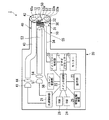
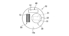
まず、本実施形態の内視鏡装置1の構成について説明する。図1は、内視鏡装置1の構成を示すブロック図である。図2は、内視鏡装置1における挿入部10の先端面を示す正面図である。
Hereinafter, an endoscope apparatus and a measurement method according to an embodiment of the present invention will be described.
First, the configuration of the endoscope apparatus 1 according to the present embodiment will be described. FIG. 1 is a block diagram showing a configuration of the endoscope apparatus 1. FIG. 2 is a front view showing the distal end surface of the
内視鏡装置1は、被検物に明暗パターンが投影されたパターン投影画像を用いて被検物の計測を行う計測内視鏡である。また、内視鏡装置1は、被検物の内部観察や、通常の観察装置がアクセス困難な位置にある被検物の観察などに使用される。 The endoscope apparatus 1 is a measurement endoscope that performs measurement of a test object using a pattern projection image in which a light and dark pattern is projected onto the test object. The endoscope apparatus 1 is used for internal observation of a test object, observation of a test object at a position where a normal observation apparatus is difficult to access, and the like.
図1に示すように、内視鏡装置1は、長尺の挿入部10と、挿入部10の基端が接続された本体部20とを備える。
挿入部10は、管状に形成されており、被検物の内部または被検物へのアクセス経路に挿入される。挿入部10には、被検物の画像を取得する撮像部30と、挿入部10前方の観察視野を照明する照明部40と、被検物に明暗パターンを投影するパターン投影部50とが設けられている。本実施形態では、パターン投影部50は明暗パターンとして、縞パターンを披検物に投影するものとする。
図2に示すように、挿入部10の先端面10aには、撮像部30の対物光学系32に外光を入射させるための開口11と、照明部40からの照明光を挿入部10の前方に照射するための照明窓12と、パターン投影部50からの縞パターンを挿入部10の前方に照射するための投影窓13とが設けられている。
As shown in FIG. 1, the endoscope apparatus 1 includes a
The
As shown in FIG. 2, the
撮像部30は、挿入部10の先端付近に配置されたイメージャー31と、イメージャー31の前方に配置された対物光学系32と、イメージャー31と接続されたイメージャー制御部33とを備える。
The
イメージャー31としては、例えば正方形状の画素が格子状に配列された長方形状のセンサー領域を有し、センサー領域に入射する光量を画素ごとに検出して画像を撮像するエリアイメージセンサーを採用することができる。本明細書では、イメージャー31によって撮像される画像について、イメージャー31のセンサー領域における短辺側を縦、長辺側を横と表記する。イメージャー31の具体例としては、CCD、CMOS等の各種イメージセンサを含む公知の各種構成を適宜選択して用いることができる。
As the
対物光学系32は、挿入部10の開口11内に配置されている。対物光学系32は、所定の画角(視野角)を有し、当該画角により規定される観察視野内の反射光をイメージャー31に入射させ、被検物の像を結像させる。また、対物光学系32は、開口11を封止する光透過性のカバー部材32aを有する。
The objective
イメージャー制御部33は、本体部20内に設けられており、挿入部10内を延びる配線34によりイメージャー31と接続されている。イメージャー制御部33は、イメージャー31の駆動および映像信号を取得する設定等の各種制御を行う。
The
照明部40は、第一光源41と、照明光学系42と、第一光源41の光を照明光学系42に導く第一ファイバーバンドル43と、第一光源41と第一ファイバーバンドル43との間に配置される第一入射光学系44とを備える。
The
第一光源41は、白色光を発する光源であり、本体部20の内部に配置されている。第一光源41としては、ハロゲンランプや水銀ランプなど、公知の光源を適宜選択して採用することができる。本実施形態では、第一光源41として、ハロゲンランプが採用されている。第一光源41から発せられる光は、被検物を照明するための照明光となる。
The
照明光学系42は、挿入部10の先端または先端付近に取り付けられている。照明光学系42は、挿入部10の照明窓12内に設けられた光透過性のカバー部材42aと、図示しないレンズ群とを有する。照明光学系42は、第一光源41から照射された光を対物光学系32の画角に適した視野範囲に広げて照明窓12から出射させ、観察視野をまんべんなく照明する。
The illumination
第一ファイバーバンドル43は、照明光学系42の近傍から挿入部10を通って本体部20内の第一光源41近傍まで延びている。第一ファイバーバンドル43の種類には特に制限はなく、一般的なライトガイドを使用可能である。
The
第一入射光学系44は、第一光源41から発せられる光を第一ファイバーバンドル43の径と同程度まで収束させて効率よく第一ファイバーバンドル43内に導入する。
The first incident
パターン投影部50は、第二光源51と、投影光学系52と、第二光源51の光を投影光学系52に導く第二ファイバーバンドル53と、第二光源51と第二ファイバーバンドル53との間に配置される第二入射光学系54と、第二光源51から出射された光の光路上に配置されたパターン生成部55とを備える。
The
第二光源51は、第一光源41とは異なる光を発する光源であり、本体部20の内部に配置されている。第二光源51としては、LED光源やレーザー光源などを採用することができる。本実施形態では、第二光源51としてLED光源が採用されている。第二光源51から発せられる光は、縞パターンを投影するための投影光となる。
The second
投影光学系52は、挿入部10の先端または先端付近に取り付けられている。投影光学系52は、挿入部10の投影窓13内に設けられた光透過性のカバー部材52aを有する。図2に示すように、投影窓13は、挿入部10の先端面10a側から見たときに、イメージャー31の短辺側に隣接する位置に配置されている。
なお、投影窓13に設けられたカバー部材52aはレンズ形状であっても構わない。投影光学系52は、第二光源51から照射された光を、対物光学系32の画角に対応した所定の照射角度で1つの投影窓13から観察視野内に投影する。
The projection
Note that the
ここで、本実施形態における対物光学系32の画角と投影光学系52による投影光の照射角度の関係について詳述する。
図3は、対物光学系32の画角と投影光学系52の照射角度との関係を示す模式図である。図3において、符号Oは対物光学系32の位置を示し、符号Pは投影光学系52の位置を示す。
Here, the relationship between the angle of view of the objective
FIG. 3 is a schematic diagram showing the relationship between the field angle of the objective
図3に示すように、本実施形態では、対物光学系32の画角θvは、対物光学系32の深度方向(物体距離の方向)を中心線(図3に符号A1で示す。)として等角度に広がっている。また、投影光学系52の照射角度θpは、中心線A1と平行な中心線A2を中心として等角度に広がっている。さらに、対物光学系32の画角θvと投影光学系52の照射角度θpは、θv>θpを満たす。
As shown in FIG. 3, in the present embodiment, the angle of view θv of the objective
また、対物光学系32における近点側の深度をLnとし、遠点側の深度をLfとしたときに、投影される全ての縞が視野内に入る最短の物体距離L1は、Ln≧L1を満たす。
このような関係であれば、焦点が合っている物体距離(LnからLfまでの深度内)であるときには、縞パターンはすべて対物光学系32の画角内に位置している。
Further, when the depth on the near point side in the objective
With such a relationship, all the fringe patterns are located within the angle of view of the objective
また、本実施形態では、対物光学系32の中心と投影光学系52の中心との距離dは、計測可能な物体距離の最小値である深度L1よりも小さく設定されている。このため、距離dは、物体距離Lnよりも十分に小さい。このため、撮像部30において焦点が合っている範囲では画像に写る縞の位置は大きくは変わらない。
In the present embodiment, the distance d between the center of the objective
図1に示すように、第二ファイバーバンドル53は、投影光学系52の近傍から挿入部10を通って本体部20内の第二光源51近傍まで延びている。第二ファイバーバンドル53としては、第一ファイバーバンドル43と同様に一般的なライトガイドを使用することができる。
As shown in FIG. 1, the
第二入射光学系54は、第二光源51から発せられた光を、第二ファイバーバンドル53の径と同程度まで収束させて効率よく第二ファイバーバンドル53内に導入する。
The second incident
パターン生成部55は、縞パターンを形成可能なもので、例えば複数のスリットを有するスリット板や、ガラスや樹脂等からなる透明な板に縞パターンが描かれたものなどを用いることができる。縞パターンは、縞の輝度がなだらかに周期的に変化するような帯状の縞模様であることが好ましい。また、縞パターンは、白または黒など矩形状に輝度が変化するような縞模様であってもよい。
The
本実施形態における縞パターンは、イメージャー31のセンサー領域の短辺方向に延びイメージャー31のセンサー領域の長辺方向に所定間隔おきに平行に配置されるパターンとなっている(図2参照)。すなわち、本実施形態では、縞パターンは、挿入部の先端と正対する平面に投影されたときに、撮像部30によって取得された画像の縦方向に延びて横方向に並ぶ互いに平行な線として写る(図4参照)。
The stripe pattern in the present embodiment is a pattern that extends in the short side direction of the sensor region of the
このほか、素子ごとに光の透過と不透過を切り替え可能な液晶シャッターモジュールや、素子ごとに微細な反射ミラーを備えるMEMS(マイクロ電子機器システム)ミラーモジュール等がパターン生成部55として用いられてもよい。この場合、素子ごとの制御を行うので、パターン生成部55全体を移動させずに適切な位相の縞パターンを形成することができるため、パターン投影部50の構成を簡素にすることができる利点がある。縞パターンの切り替えは、パターン生成部55に接続されたパターン制御部56によって行われる。
In addition, a liquid crystal shutter module that can switch between transmission and non-transmission of light for each element, a MEMS (microelectronic device system) mirror module that includes a fine reflection mirror for each element, and the like may be used as the
図4は、被検物に投影された縞パターンの一例を示す模式図である。
図3および4に示すように、対物光学系32の画角θvと投影光学系52の照射角度θpとが上述の関係となっていることにより、パターン投影部50は、被検物に対して縞パターン(図4に符号100で示す)が投影されている状態において、撮像部30の撮像視野内で縞パターンの縞が並ぶ方向の両端に、縞パターンが投影されていない未投影領域X(右側未投影領域X1および左側未投影領域X2)を生じさせる。
また、対物光学系32の画角と投影光学系52における投影光の照射角度の関係は、θp≧θvとなっていても良い。この場合は、全ての縞パターンが対物光学系32の画角内に位置しないが、撮像視野内で縞パターンの縞が並ぶ方向のどちらか一方に、縞パターンが投影されていない未投影領域X(右側未投影領域X1または左側未投影領域X2)を生じさせる。
FIG. 4 is a schematic diagram illustrating an example of a fringe pattern projected onto the test object.
As shown in FIGS. 3 and 4, since the angle of view θv of the objective
Further, the relationship between the field angle of the objective
本体部20内には、上述のイメージャー制御部33と、照明部40から照明光を出射する動作およびパターン投影部50から投影光を出射する動作を制御する光源制御部21と、メイン制御部22とが設けられている。
In the
イメージャー制御部33には、イメージャー31の取得した映像信号を処理するビデオプロセッサー27と、イメージャー制御部33の動作を制御するメイン制御部22とが接続されている。ビデオプロセッサー27およびメイン制御部22は本体部20内に設けられている。
Connected to the
ビデオプロセッサー27には、ビデオプロセッサー27によって処理された映像信号を画像として表示する表示画面を有するモニター(表示部)28が接続されている。ビデオプロセッサー27は、被検物に投影される縞パターンの表示画面上における投影予定位置を示す枠Fとなる画像を生成し、撮像部30によって取得された画像に重ねてモニター28へ出力する。
図3に示す距離dは、物体距離Lnや物体距離Lfに比べて十分に小さいので、モニター28上に写る縞パターンの位置は大きくは変わらず、ある程度の範囲内で左右に移動する。つまり、縞パターンの位置は、モニター28に表示される画像上において、被検物に対する物体距離に応じて僅かに横方向に移動する。
The
Since the distance d shown in FIG. 3 is sufficiently smaller than the object distance Ln and the object distance Lf, the position of the stripe pattern on the
図5(A)および図5(B)は、内視鏡装置1のモニターに表示される枠Fを示す模式図である。図5(A)および図5(B)に示すように、本実施形態では、縞パターン100が横方向に最大限移動しても縞パターン100が表示される領域を囲むように枠Fの位置が設定される。これにより、モニター28に表示される画像における実際の縞パターン100の位置に係わらず、枠F内には縞パターン100が位置することとなる。このように枠Fの位置を設定した場合には、縞パターン100の位置に対応させて枠Fの位置を調整する必要がないので、枠Fを表示させるための処理が簡単である。
モニター28は、被検物の画像と、縞パターンの投影予定位置を示す枠Fとを表示画面に表示する。また、モニター28には、三次元形状の計測結果や、内視鏡装置1の使用中に検出される各種情報が表示される。
FIG. 5A and FIG. 5B are schematic views showing a frame F displayed on the monitor of the endoscope apparatus 1. As shown in FIG. 5A and FIG. 5B, in the present embodiment, the position of the frame F so as to surround the area where the
The
図1に示すように、光源制御部21は、第一光源41および第二光源51、並びにメイン制御部22に接続されており、メイン制御部22による制御に基づいて第一光源41および第二光源51のオン/オフを制御する。
As shown in FIG. 1, the light
メイン制御部22は、さらに、操作部23、RAM24、ROM26、補助記憶装置25、およびパターン制御部56に接続されている。
The
操作部23は、使用者が内視鏡装置1に各種入力を行うためのスイッチなどを有する。また、操作部23として、モニター28の表示画面と重ねて設けられたタッチパネルが採用されてもよい。
The
RAM24は、内視鏡装置1を用いた被検物の撮像や三次元形状の計測などの際に使用されるワークエリアとして機能する。
ROM26は、たとえばファームウェア等が記録されており、内視鏡装置1の起動時にファームウェア等が読み出されるようになっている。
補助記憶装置25は、たとえば書き換え可能な不揮発メモリを有する記憶装置や磁気記憶装置などを採用することができる。
The
The
As the
メイン制御部22は、ビデオプロセッサー27によって生成された枠Fによって囲まれる画像上の領域を、三次元形状を計測するための対象領域T(図4参照)に設定し、対象領域T内のみに対して被検物の三次元形状を求める。
メイン制御部22によって被検物の三次元形状を計測するための計測方法としては、位相シフト法やフーリエ変換法などによって縞パターンの位相を求めて、縞パターンの位相に基づいて被検物の三次元形状を計算する方法を用いることができる。
The
As a measurement method for measuring the three-dimensional shape of the test object by the
以上に説明した構成の内視鏡装置の作用について説明する。
内視鏡装置1の使用時には、まず、使用者は、図1に示す挿入部10を被検物の内部や管路等の被検物へのアクセス経路等に挿入し、所定の観察部位まで挿入部10の先端を進める。使用者は、被検物の所望の部位を観察する観察モードと、当該部位の三次元形状を計測する計測モードとを必要に応じて切り替えることにより、被検物の検査等を行う。
The operation of the endoscope apparatus having the above-described configuration will be described.
When using the endoscope apparatus 1, first, the user inserts the
観察モードでは、図2に示すメイン制御部22の指令を受けて光源制御部21が第一光源41をオン制御し、第二光源51をオフ制御する。その結果、パターン投影部50からは縞パターンが投影されずに照明部40から観察視野に白色光が照射され、観察視野が照明される(以下、この照明状態を「観察状態」と称する。)。照明された被検物の像は、対物光学系32を通してイメージャー31に結像される。イメージャー31から送られた映像信号は、ビデオプロセッサー27で処理されてモニター28に表示される。使用者は、モニター28に表示される被検物の画像により被検物を観察したり、必要に応じて画像を保存したりすることができる。
In the observation mode, the
観察モードから計測モードへ切り替える場合には、モードを切り替える指示を使用者が入力する。観察モードから計測モードへ切り替える入力が使用者によって行われると、メイン制御部22からビデオプロセッサー27へ、枠Fの画像をモニター28に表示させるための制御信号が出力される。これにより、モニター28には、縞パターンの投影予定位置に対応した枠Fの画像が表示される(図5(A)および図5(B)参照。)。
なお、この状態では、縞パターン100はまだ投影されておらず、使用者は、照明光によって照明された被検物の映像を観察することができる。
When switching from the observation mode to the measurement mode, the user inputs an instruction to switch the mode. When an input for switching from the observation mode to the measurement mode is performed by the user, a control signal for displaying the image of the frame F on the
In this state, the
使用者は、被検物において三次元形状の計測を所望する部位がモニター28上の枠F内に入るように、挿入部10の位置などを調整する。モニター28上に表示された枠F内に所望の部位が位置している状態で、使用者は操作部23における図示しないスイッチなどを用いて三次元形状の計測を開始させる。
The user adjusts the position of the
三次元形状の計測が開始されると、まず、図1に示す照明部40からの照明光が照射されている状態で少なくとも1枚の画像が撮像部30によって取得される。続いて、照明部40の第一光源41からの照明光の出射が光源制御部21によって停止され、パターン投影部50の第二光源51からの投影光の出射が光源制御部21によって開始される。
投影光が出射されると、投影光はパターン生成部55および投影光学系52を透過し、縞パターンが被検物に投影される。
図3に示すように、被写体に縞パターンを投影した場合には、対物光学系32の画角内の一部に縞パターンが投影され、撮像部30の撮像視野内で縞パターンの縞が並ぶ方向の両端に、縞パターンが投影されていない未投影領域Xが生じる。
When the measurement of the three-dimensional shape is started, first, at least one image is acquired by the
When the projection light is emitted, the projection light passes through the
As shown in FIG. 3, when a fringe pattern is projected onto the subject, the fringe pattern is projected onto a part of the angle of view of the objective
なお、物体距離に応じて、対物光学系32の画角内における縞パターンの位置は異なる。しかし、本実施形態では、対物光学系32の中心と投影光学系52の中心との距離dが、計測可能な物体距離よりも十分に小さく設定されているので、縞が画面上に写る位置は大きくは変化しない。このため、縞パターンの位置が移動しても縞パターンの位置はあらかじめ設定した略枠F内に収まるようになっている(図5(A)および図5(B)参照)。
Note that the position of the fringe pattern within the angle of view of the objective
縞パターンが被検物に投影されている状態で、撮像部30は被検物の画像を取得する。縞パターンが投影された状態の被検物の画像は、縞画像として、図1に示すビデオプロセッサー27を介してメイン制御部22へと出力され、RAM24などに一時記憶される。
The
そして、メイン制御部22によって、撮像部30で取得した1枚のパターン投影画像から上述の位相シフト法やフーリエ変換法などによって縞パターンの位相を求める。
Then, the
また、時間的位相シフト法を用いて三次元形状の計測を行う場合には、位相が異なる複数のパターン投影画像を撮像部30が撮像し、メイン制御部22によって、複数のパターン投影画像に写った縞パターンの位相を求める。本実施形態の内視鏡装置1では、撮影された複数のパターン投影画像の各々は、縞パターンが投影されていない未投影領域Xが少なくとも一部に生じているので、縞パターンが投影されている領域と上記未投影領域Xとの境界を起点として、パターン投影画像上に写っている縞と投影された縞パターンの縞とを対応付けることが比較的容易にできる。これにより、求められた前記位相から実空間上の三次元座標を計算することができる。そして、被検物の三次元形状を計測する対象となる対象領域T(つまり、計測可能な視野範囲)が、枠Fの内側の領域に設定されている場合は、対象領域T内における三次元座標の分布を求めることで、被検物の三次元形状を求めることができる。なお、被検物の三次元形状を計測する演算は、対象領域T内に限定せずに、明暗パターンが写っている範囲で行ってもよい。
Further, when measuring a three-dimensional shape using the temporal phase shift method, the
メイン制御部22によって演算した結果は、モニター28上に数値若しくは画像として表示するためにビデオプロセッサー27へ出力される。また、演算した結果を補助記憶装置25にファイルとして格納してもよい。
The result calculated by the
モニター28上に演算した結果が表示されることにより、使用者は、枠F内における被検物の三次元形状を知ることができる。
By displaying the calculation result on the
以上説明したように、本実施形態の内視鏡装置1によれば、撮像部30の撮像視野内で縞パターンの縞が並ぶ方向の両端、あるいは一方に、縞パターンが投影されていない未投影領域Xを生じさせることにより、パターン投影画像に写っている縞と、被検物に投影された縞とを容易に対応付けることができる。これにより、被検物の物体距離をパターン投影画像の計測により得ることができる。
パターン投影画像に写っている縞パターンと、被検物に投影された縞パターンとを容易に対応付ける別の方法としては、投影光学系52が配置される開口を2つ設けて、2つの方向から縞パターンをそれぞれ投影する方法が知られているが、本実施形態では、挿入部10の先端部には投影光学系52が配置される開口を1つだけ設ければよいため、挿入部10をより細径にすることができる。あるいは、被検物へ投影された縞パターンと、被検物の物体距離を別途測定するセンサーを併用して、被検物の三次元形状を測定する方法も知られているが、本実施形態では、被検物の物体距離を別途測定するセンサーを搭載する必要がなくなるので、挿入部10をより細径にすることができる。
As described above, according to the endoscope apparatus 1 of the present embodiment, the non-projection in which the fringe pattern is not projected on both ends or one side in the direction in which the stripes of the fringe pattern are arranged within the imaging field of view of the
As another method for easily associating the fringe pattern reflected in the pattern projection image with the fringe pattern projected on the test object, two openings for arranging the projection
また、被検物に焦点が合っていればパターン投影画像上に未投影領域Xが必ず生じるので、使用者は、被検物に焦点を合わせて三次元形状の計測を開始させるだけでよく、内視鏡装置1の操作が簡便である。 In addition, since the unprojected region X is necessarily generated on the pattern projection image if the object is in focus, the user only has to start the measurement of the three-dimensional shape by focusing on the object. The operation of the endoscope apparatus 1 is simple.
また、撮像部の撮像視野内で縞パターンの縞が並ぶ方向の両端、あるいは一方に未投影領域を生じさせるので、パターン投影画像上に写っている縞パターンと投影された縞パターンとを対応付けることが比較的容易にできるため、縞パターン解析時の誤認識を低減することができ、計測値の信頼性や計測性能の悪化を防ぐことができる。 In addition, an unprojected area is generated at both ends or one side in the direction in which the stripes of the stripe pattern are arranged in the imaging field of the imaging unit, so that the stripe pattern reflected on the pattern projection image is associated with the projected stripe pattern. Therefore, it is possible to reduce the misrecognition during the fringe pattern analysis and to prevent the reliability of the measurement value and the deterioration of the measurement performance.
また、メイン制御部22およびビデオプロセッサー27によって、モニター28の表示画面に、被検物に投影される縞パターンの投影予定位置を示す枠Fを表示するので、内視鏡装置1の使用時に、三次元形状の計測をすることができる領域を使用者に知らせることができる。
Further, since the
また、物体距離に応じて縞パターンの位置が変わっても縞パターンは略枠F内に投影されるので、三次元形状の計測をすることができる領域を確認するために実際に縞パターンを投影する必要がなく、内視鏡装置による計測操作を簡単にすることができる。 Even if the position of the fringe pattern changes according to the object distance, the fringe pattern is projected almost in the frame F, so the fringe pattern is actually projected to confirm the area where the three-dimensional shape can be measured. It is not necessary to perform this, and the measurement operation by the endoscope apparatus can be simplified.
また、メイン制御部22が、枠F内を対象領域Tとして対象領域Tのみに対して三次元形状の計測を行う場合は、画像全体に縞パターンを写して画像の全領域で三次元形状を演算する場合よりも演算量を減らすことができ、三次元形状の演算結果を迅速に得ることができる。
In addition, when the
また、対物光学系32の画角より投影光の照射角度が小さいので、投影光の照射角度を対物光学系32の画角以上とする場合と比較して、投影窓13を小型化しやすい。このため、挿入部10をさらに細径化することができる。
Further, since the irradiation angle of the projection light is smaller than the angle of view of the objective
(変形例1)
次に、上述の実施形態で説明した内視鏡装置1の変形例について説明する。
図6は、本変形例における対物光学系32の画角θvと投影光学系52の照射角度θpとの関係を示す模式図である。
図6において、符号αおよび符号βは、投影光学系52による投影光の照射角度を示している。具体的には、符号αは対物光学系32の深度方向に対する左側の照射角度を示し、符号βは対物光学系32の深度方向に対する右側の照射角度を示している。図6に示されたその他の符号については上述の実施形態で説明した通りである。
(Modification 1)
Next, a modified example of the endoscope apparatus 1 described in the above embodiment will be described.
FIG. 6 is a schematic diagram showing the relationship between the angle of view θv of the objective
In FIG. 6, reference symbols α and β indicate irradiation angles of projection light by the projection
図6に示すように、投影光学系52による投影光の照射角度θpの大きさは、左側の照射角度αと、右側の照射角度βとの和となっている。本変形例では、投影光の照射角度θpが、深度方向の中心線に対して左右等角度ではない点で上述の実施形態と構成が異なっている。
本変形例では、投影される全ての縞が対物光学系32の画角内に入る物体距離をL1からL2の範囲内とすると、Ln≧L1かつLf≦L2となっている場合であり、さらに物体距離が深度内(Ln〜Lfの範囲)であれば、全ての縞を視野内に写すことができる。また、このとき、対物光学系32の画角θvおよび縞投影の照射角度θpは、θv>θpの関係も満たしている。
As shown in FIG. 6, the projection light irradiation angle θp by the projection
This modification is a case where Ln ≧ L1 and Lf ≦ L2, where the object distance where all projected fringes fall within the angle of view of the objective
対物光学系32の画角θvと投影光の照射角度θpがこのような関係にある場合にも、上述の実施形態と同様に、撮像部30の撮像視野内で縞パターンの縞が並ぶ方向の一端に、縞パターンが投影されていない未投影領域Xを生じさせることができる。
Even in the case where the angle of view θv of the objective
(変形例2)
次に、上述の実施形態で説明した内視鏡装置1の他の変形例について説明する。
本変形例では、枠Fの画像を生成するビデオプロセッサー27が、枠Fの位置を調整する手段をさらに備えていることを特徴としている。
(Modification 2)
Next, another modified example of the endoscope apparatus 1 described in the above embodiment will be described.
This modification is characterized in that the
上述の実施形態の内視鏡装置1における枠Fの設定方法では、枠Fの外側の領域においても縞パターンが実際には表示される場合がある。実際の縞パターンの投影位置にあわせて枠Fの位置を変更する手段をさらに備えることにより、三次元形状の計測をすることができる領域をより正確に使用者に示すことができる。 In the setting method of the frame F in the endoscope apparatus 1 of the above-described embodiment, a stripe pattern may actually be displayed even in an area outside the frame F. By further providing means for changing the position of the frame F in accordance with the actual projection position of the fringe pattern, the area where the three-dimensional shape can be measured can be shown to the user more accurately.
具体的には、枠Fの形状を調整する手段は、縞パターンにおける複数の縞の左右両端を高速に検出して、縞パターンの輪郭に合わせて枠Fを表示する。その際、縞パターンが常時投影されていると、その縞パターンが被検物の観察において邪魔になるため、例えば、1秒間のうちたとえば1/30秒だけ縞パターンを被検物に投影する等、観察に支障がない範囲で短時間だけ縞パターンの投影を行う。縞の左右両端を高速に検出する方法としては、縞パターンが投影された状態で被検物の画像を取得し、取得された画像から縞のエッジ検出によって行う。 Specifically, the means for adjusting the shape of the frame F detects the left and right ends of the plurality of stripes in the stripe pattern at high speed and displays the frame F in accordance with the outline of the stripe pattern. At that time, if the fringe pattern is always projected, the fringe pattern becomes an obstacle in observing the test object. For example, the fringe pattern is projected onto the test object for 1/30 sec in one second, for example. The fringe pattern is projected for a short time within a range that does not hinder observation. As a method of detecting the left and right ends of the stripe at high speed, an image of the test object is acquired in a state where the stripe pattern is projected, and the edge of the stripe is detected from the acquired image.
エッジ検出は、画像中央部の1ラインのみ、あるいは所定の複数ラインのみなど、一部分に限ってもよい。これにより、エッジ検出のための演算量を少なくすることができる。また、エッジ検出のための演算速度が十分に得られるのであれば、より正確に枠Fを表示するために、画像上の全ラインでエッジ検出した結果から、枠Fを表示するようにしてもよい。 The edge detection may be limited to a part such as only one line at the center of the image or only a predetermined plurality of lines. Thereby, the calculation amount for edge detection can be reduced. Further, if the calculation speed for edge detection is sufficiently obtained, in order to display the frame F more accurately, the frame F may be displayed from the result of edge detection in all the lines on the image. Good.
また、この枠Fの表示は、例えば1秒毎など、所定の間隔で更新される。縞パターンの投影自体は、被検物に照明光を照射して被検物を観察する場合の妨げにならない程度の短時間だけ行われているので、被写体を画面上で観察する上で支障とならずに枠Fをモニター28に略リアルタイムで表示することができる。
The display of the frame F is updated at a predetermined interval, for example, every second. The projection of the fringe pattern itself is performed for a short period of time that does not interfere with the observation of the test object by illuminating the test object, which is an obstacle to observing the subject on the screen. Instead, the frame F can be displayed on the
このように、本変形例では、実際に被検物に投影された縞パターンに基づいて枠Fの形状が設定される。このため、上述の実施形態で説明した方法によって枠Fを設定する場合と比較して、三次元形状を計測できる領域を正しく使用者に示すことができる。
また、枠Fの表示が所定の間隔で更新されるので、縞パターンが実際に投影される領域を所定の間隔で最新の状態とすることができる。このため、枠F内であっても縞パターンが投影されないという事態が生じることを軽減することができる。
Thus, in this modification, the shape of the frame F is set based on the fringe pattern actually projected onto the test object. For this reason, compared with the case where the frame F is set by the method demonstrated in the above-mentioned embodiment, the area | region which can measure a three-dimensional shape can be shown correctly to a user.
In addition, since the display of the frame F is updated at a predetermined interval, the region where the fringe pattern is actually projected can be updated to the latest state at the predetermined interval. For this reason, even if it exists in the frame F, it can reduce that the situation where a fringe pattern is not projected arises.
以上、本発明の実施形態について図面を参照して詳述したが、具体的な構成はこの実施形態に限られるものではなく、本発明の要旨を逸脱しない範囲の設計変更等も含まれる。
たとえば、上述の実施形態では、対物光学系が配置される開口、照明光学系が配置される開口、投影光学系が配置される開口がそれぞれ1つ設けられている例を用いて説明したが、これらの開口は2つ以上設けられていてもよい。
As mentioned above, although embodiment of this invention was explained in full detail with reference to drawings, the concrete structure is not restricted to this embodiment, The design change etc. of the range which does not deviate from the summary of this invention are included.
For example, in the above-described embodiment, the description has been given using the example in which one opening provided with the objective optical system, one opening provided with the illumination optical system, and one opening provided with the projection optical system are provided. Two or more of these openings may be provided.
また、上述の実施形態では、撮像部によって撮像される画像の縦方向に延びる縞を投影する投影部が対物光学系に対して左右方向に並んでいる例を示したが、撮像部によって撮像される画像の横方向に延びる縞を投影する投影部が対物光学系に対して上下方向に並んでいてもよい。あるいは、明暗パターンの形状は、帯状の縞ではなく、複数の縦帯と横帯が交差した格子状のパターンや、等間隔に縦横に並んだ複数の点であってもよい。 In the above-described embodiment, the example in which the projection unit that projects the stripe extending in the vertical direction of the image captured by the imaging unit is arranged in the left-right direction with respect to the objective optical system is shown. Projectors that project stripes extending in the horizontal direction of the image may be arranged in the vertical direction with respect to the objective optical system. Alternatively, the shape of the light / dark pattern may not be a striped stripe, but may be a lattice pattern in which a plurality of vertical and horizontal bands intersect, or a plurality of points arranged vertically and horizontally at equal intervals.
また、上述の実施形態では、照明光を照射するための第一光源と投影光を照射するための第二光源とが本体部内に配置された例を示したが、第一光源および第二光源は、挿入部の先端に設けられていてもよい。 Moreover, in the above-mentioned embodiment, although the 1st light source for irradiating illumination light and the 2nd light source for irradiating projection light were shown in the main-body part, the 1st light source and the 2nd light source were shown. May be provided at the tip of the insertion portion.
また、第一光源および第二光源は、光の出射状態を切り替えるシャッターやミラーモジュール等を備えていてもよい。この場合、点灯や消灯に時間がかかる光源であっても好適に光源として使用することができる。 The first light source and the second light source may include a shutter, a mirror module, and the like that switch the light emission state. In this case, even a light source that takes time to turn on and off can be suitably used as a light source.
また、枠の形状は、上述の実施形態で示した形状以外にも、丸型、四角型、その他多角形など、適宜の形状に設定することができる。 Further, the shape of the frame can be set to an appropriate shape such as a round shape, a square shape, and other polygons other than the shapes shown in the above-described embodiments.
また、上述の実施形態では、未投影領域を、撮像部の撮像視野内で縞パターンの縞が並ぶ方向の両端に生じさせる構成について例示したが、未投影領域を、撮像部の撮像視野内で縞パターンの縞が並ぶ方向の一端に生じさせる構成としてもよい。撮像部の撮像視野内で縞パターンの縞が並ぶ方向の一端に未投影領域が生じていれば、未投影領域と縞パターンとの境界をエッジ検出などによって検出することができ、未投影領域と縞パターンとの境界を起点として、投影された縞パターンの縞と画像上の縞とを対応付けることができる。 Further, in the above-described embodiment, an example in which the unprojected areas are generated at both ends in the direction in which the stripes of the stripe pattern are arranged in the imaging field of the imaging unit is illustrated. However, the unprojected areas are generated in the imaging field of the imaging unit. It is good also as a structure produced in the end of the direction where the stripe of a stripe pattern arranges. If there is an unprojected area at one end in the direction in which the stripes of the stripe pattern are arranged within the imaging field of the imaging unit, the boundary between the unprojected area and the stripe pattern can be detected by edge detection or the like. Starting from the boundary with the stripe pattern, the stripe of the projected stripe pattern and the stripe on the image can be associated with each other.
また、上述の実施形態で説明した縞パターン生成部に代えて、格子状や点状の模様などのパターンを生成する生成部を有していてもよい。 Moreover, it may replace with the striped pattern production | generation part demonstrated by the above-mentioned embodiment, and may have the production | generation part which produces | generates patterns, such as a grid | lattice form and a dot-like pattern.
1 内視鏡装置
10 挿入部
28 モニター(表示部)
30 撮像部
31 イメージャー(撮像素子)
32 対物光学系
40 照明部
41 第一光源
42 照明光学系
50 パターン投影部
51 第二光源
52 投影光学系
55 パターン生成部
F 枠
T 対象領域
X 未投影領域
1
30
32 Objective
Claims (5)
長尺の挿入部と、
前記挿入部の先端部に設けられ、前記被検物の画像を取得する撮像部と、
前記撮像部の観察視野を照明する照明部と、
前記被検物に前記明暗パターンを投影するための投影光を発する光源が設けられたパターン投影部と、
前記被検物の画像を表示する表示画面を有する表示部と、
を備え、
前記パターン投影部は、
前記被検物に対して前記明暗パターンが投影されている状態において、前記撮像部の撮像視野内で前記明暗パターンの縞が並ぶ方向の少なくとも一端に前記明暗パターンが投影されていない領域を生じさせ、
前記表示部は、
前記被検物に投影される前記縞パターンの前記表示画面上における投影予定位置を示す枠を前記表示画面上に表示する
ことを特徴とする内視鏡装置。 An endoscope apparatus for measuring the test object using a fringe image in which a light and dark pattern is projected on the test object,
A long insertion part,
An imaging unit that is provided at a distal end of the insertion unit and acquires an image of the test object;
An illumination unit that illuminates the observation field of view of the imaging unit;
A pattern projection unit provided with a light source that emits projection light for projecting the bright and dark pattern onto the test object;
A display unit having a display screen for displaying an image of the test object;
With
The pattern projection unit
In a state where the light / dark pattern is projected onto the test object, a region where the light / dark pattern is not projected is generated at least at one end in a direction in which the stripes of the light / dark pattern are arranged in the imaging field of view of the imaging unit. ,
The display unit
An endoscope apparatus , wherein a frame indicating a projected position on the display screen of the stripe pattern projected onto the test object is displayed on the display screen .
前記撮像部は、
被検物の画像を撮像する撮像素子と、
前記被検物の像を前記撮像素子に結像させる対物光学系と、
を備え、
前記投影部は、
前記明暗パターンを生成するパターン生成部と、
前記挿入部の先端部に設けられ、前記明暗パターンを介して前記光源から前記被検物に前記投影光を照射する投影光学系と、
を備え、
前記対物光学系の画角よりも前記投影光学系における前記投影光の照射角度の方が狭いことを特徴とする内視鏡装置。 The endoscope apparatus according to claim 1,
The imaging unit
An image sensor for capturing an image of the test object;
An objective optical system that forms an image of the test object on the imaging device;
With
The projection unit
A pattern generator for generating the light and dark pattern;
A projection optical system that is provided at a distal end portion of the insertion portion and that irradiates the projection light from the light source to the test object via the brightness pattern;
With
An endoscope apparatus, wherein an irradiation angle of the projection light in the projection optical system is narrower than an angle of view of the objective optical system.
前記撮像部の撮像視野内で前記明暗パターンの縞が並ぶ方向の少なくとも一端に前記明暗パターンが投影されていない領域が生じている状態において、前記対物光学系の焦点が合っていることを特徴とする内視鏡装置。 The endoscope apparatus according to claim 1 or 2, wherein
The objective optical system is in focus in a state in which a region where the light / dark pattern is not projected is generated at least at one end in the direction in which the stripes of the light / dark pattern are arranged in the imaging field of view of the imaging unit. Endoscope device.
前記被検物に前記明暗パターンを投影するための投影窓が、前記挿入部の先端面に1つだけ設けられていることを特徴とする内視鏡装置。 The endoscope apparatus according to any one of claims 1 to 3,
An endoscope apparatus, wherein only one projection window for projecting the light / dark pattern onto the test object is provided on a distal end surface of the insertion portion.
前記表示画面に表示された画像上で前記枠内に位置する領域のみに対して前記被検物の三次元形状の計測を行う制御部をさらに備えることを特徴とする内視鏡装置。 The endoscope apparatus according to claim 1 ,
An endoscope apparatus, further comprising a control unit that measures a three-dimensional shape of the test object only for a region located within the frame on an image displayed on the display screen.
Priority Applications (5)
| Application Number | Priority Date | Filing Date | Title |
|---|---|---|---|
| JP2011116140A JP5846763B2 (en) | 2011-05-24 | 2011-05-24 | Endoscope device |
| PCT/JP2012/063258 WO2012161239A1 (en) | 2011-05-24 | 2012-05-24 | Endoscope |
| EP12789379.0A EP2700348B1 (en) | 2011-05-24 | 2012-05-24 | Endoscope |
| US14/078,223 US9622644B2 (en) | 2011-05-24 | 2013-11-12 | Endoscope |
| US15/450,741 US10368721B2 (en) | 2011-05-24 | 2017-03-06 | Endoscope |
Applications Claiming Priority (1)
| Application Number | Priority Date | Filing Date | Title |
|---|---|---|---|
| JP2011116140A JP5846763B2 (en) | 2011-05-24 | 2011-05-24 | Endoscope device |
Publications (2)
| Publication Number | Publication Date |
|---|---|
| JP2012239834A JP2012239834A (en) | 2012-12-10 |
| JP5846763B2 true JP5846763B2 (en) | 2016-01-20 |
Family
ID=47217313
Family Applications (1)
| Application Number | Title | Priority Date | Filing Date |
|---|---|---|---|
| JP2011116140A Expired - Fee Related JP5846763B2 (en) | 2011-05-24 | 2011-05-24 | Endoscope device |
Country Status (4)
| Country | Link |
|---|---|
| US (2) | US9622644B2 (en) |
| EP (1) | EP2700348B1 (en) |
| JP (1) | JP5846763B2 (en) |
| WO (1) | WO2012161239A1 (en) |
Families Citing this family (17)
| Publication number | Priority date | Publication date | Assignee | Title |
|---|---|---|---|---|
| CN103501678B (en) * | 2011-01-28 | 2017-04-05 | 皇家飞利浦电子股份有限公司 | For the optical sensing of the relative tracking of endoscope |
| WO2012147679A1 (en) | 2011-04-27 | 2012-11-01 | オリンパス株式会社 | Endoscopic device and measurement method |
| JP5846763B2 (en) | 2011-05-24 | 2016-01-20 | オリンパス株式会社 | Endoscope device |
| JP5830270B2 (en) | 2011-05-24 | 2015-12-09 | オリンパス株式会社 | Endoscope apparatus and measuring method |
| JP6581083B2 (en) * | 2013-11-13 | 2019-09-25 | ダンマークス テクニスケ ユニバーシテト | Surface scanning method and related apparatus in medical imaging |
| EP3228254B1 (en) | 2014-02-21 | 2020-01-01 | 3DIntegrated ApS | A set comprising a surgical instrument |
| DE102014204243A1 (en) * | 2014-03-07 | 2015-09-10 | Siemens Aktiengesellschaft | Endoscope with depth determination |
| WO2016208664A1 (en) | 2015-06-25 | 2016-12-29 | オリンパス株式会社 | Endoscope device |
| US11020144B2 (en) | 2015-07-21 | 2021-06-01 | 3Dintegrated Aps | Minimally invasive surgery system |
| EP3145419B1 (en) | 2015-07-21 | 2019-11-27 | 3dintegrated ApS | Cannula assembly kit, trocar assembly kit and minimally invasive surgery system |
| DK178899B1 (en) | 2015-10-09 | 2017-05-08 | 3Dintegrated Aps | A depiction system |
| JP6549021B2 (en) * | 2015-11-17 | 2019-07-24 | 富士フイルム株式会社 | Endoscope system and operation method of measurement apparatus |
| FR3047076A1 (en) * | 2016-01-26 | 2017-07-28 | Commissariat Energie Atomique | DISTRIBUTED DEVICE FOR DETECTING A SUBSTANCE |
| CN109475270B (en) * | 2016-11-01 | 2021-04-27 | 奥林巴斯株式会社 | Living body observation system |
| KR102545980B1 (en) | 2018-07-19 | 2023-06-21 | 액티브 서지컬, 인크. | Systems and methods for multi-modal sensing of depth in vision systems for automated surgical robots |
| CA3132350A1 (en) | 2019-04-08 | 2020-10-15 | Stephen Tully | Systems and methods for medical imaging |
| EP4017340A4 (en) | 2019-08-21 | 2023-12-13 | Activ Surgical, Inc. | Systems and methods for medical imaging |
Family Cites Families (34)
| Publication number | Priority date | Publication date | Assignee | Title |
|---|---|---|---|---|
| JPH07104493B2 (en) | 1987-02-17 | 1995-11-13 | オリンパス光学工業株式会社 | Endoscope device |
| JPH07104491B2 (en) | 1988-02-17 | 1995-11-13 | 株式会社東芝 | Endoscope with measuring function |
| JPH0285706A (en) | 1988-09-22 | 1990-03-27 | Toshiba Corp | Measurable endoscope |
| JPH02287311A (en) | 1989-04-28 | 1990-11-27 | Toshiba Corp | Endoscope device with measuring mechanism |
| JPH03128043A (en) * | 1989-10-16 | 1991-05-31 | Toshiba Corp | Shape measurement endoscope device |
| US5434669A (en) * | 1990-10-23 | 1995-07-18 | Olympus Optical Co., Ltd. | Measuring interferometric endoscope having a laser radiation source |
| JPH0545132A (en) | 1991-08-15 | 1993-02-23 | Olympus Optical Co Ltd | Endoscope device for measurement |
| US5436655A (en) | 1991-08-09 | 1995-07-25 | Olympus Optical Co., Ltd. | Endoscope apparatus for three dimensional measurement for scanning spot light to execute three dimensional measurement |
| JP3126065B2 (en) * | 1991-12-09 | 2001-01-22 | オリンパス光学工業株式会社 | Measurement endoscope device |
| JPH0961132A (en) * | 1995-08-28 | 1997-03-07 | Olympus Optical Co Ltd | Three-dimensional-shape measuring apparatus |
| JP3816624B2 (en) | 1997-02-28 | 2006-08-30 | オリンパス株式会社 | 3D measuring device |
| JP3670789B2 (en) | 1997-02-28 | 2005-07-13 | オリンパス株式会社 | 3D shape measuring device |
| US6419626B1 (en) * | 1998-08-12 | 2002-07-16 | Inbae Yoon | Surgical instrument endoscope with CMOS image sensor and physical parameter sensor |
| US6464633B1 (en) | 1999-08-23 | 2002-10-15 | Olympus Optical Co., Ltd. | Light source device for endoscope using DMD |
| DE10104483A1 (en) | 2001-01-31 | 2002-10-10 | Forschungszentrum Fuer Medizin | Device for 3D measurement of surfaces in especially organic hollow volumes has optical imaging channel(s), projection channel(s) in endoscope shaft, fed out of shaft laterally at distal end |
| WO2003105289A2 (en) * | 2002-06-07 | 2003-12-18 | University Of North Carolina At Chapel Hill | Methods and systems for laser based real-time structured light depth extraction |
| JP4229791B2 (en) * | 2003-09-19 | 2009-02-25 | 真 金子 | Endoscope device |
| JP4916160B2 (en) | 2005-11-14 | 2012-04-11 | オリンパス株式会社 | Endoscope device |
| JP2007144024A (en) * | 2005-11-30 | 2007-06-14 | National Univ Corp Shizuoka Univ | Three-dimensional measurement endoscope using self-mixing laser |
| WO2007102195A1 (en) | 2006-03-07 | 2007-09-13 | Fujitsu Limited | Imaging apparatus and imaging method |
| JP5436757B2 (en) | 2007-03-20 | 2014-03-05 | オリンパス株式会社 | Fluorescence observation equipment |
| JP2009019941A (en) | 2007-07-11 | 2009-01-29 | Nikon Corp | Shape measuring method |
| JP2009061014A (en) * | 2007-09-05 | 2009-03-26 | Fujifilm Corp | Hardness measuring apparatus, hardness measuring method and endoscopic system |
| US7821649B2 (en) | 2008-03-05 | 2010-10-26 | Ge Inspection Technologies, Lp | Fringe projection system and method for a probe suitable for phase-shift analysis |
| US8107083B2 (en) | 2008-03-05 | 2012-01-31 | General Electric Company | System aspects for a probe system that utilizes structured-light |
| JP2009240621A (en) * | 2008-03-31 | 2009-10-22 | Hoya Corp | Endoscope apparatus |
| JP5073564B2 (en) | 2008-04-15 | 2012-11-14 | オリンパス株式会社 | Endoscope device for measurement and program |
| US8334900B2 (en) * | 2008-07-21 | 2012-12-18 | The Hong Kong University Of Science And Technology | Apparatus and method of optical imaging for medical diagnosis |
| JP5127639B2 (en) | 2008-09-10 | 2013-01-23 | 富士フイルム株式会社 | Endoscope system and method of operating the same |
| EP2272417B1 (en) * | 2009-07-10 | 2016-11-09 | GE Inspection Technologies, LP | Fringe projection system for a probe suitable for phase-shift analysis |
| JP2011229850A (en) | 2010-04-30 | 2011-11-17 | Fujifilm Corp | Endoscopic system, method and program |
| WO2012147679A1 (en) | 2011-04-27 | 2012-11-01 | オリンパス株式会社 | Endoscopic device and measurement method |
| JP5830270B2 (en) | 2011-05-24 | 2015-12-09 | オリンパス株式会社 | Endoscope apparatus and measuring method |
| JP5846763B2 (en) | 2011-05-24 | 2016-01-20 | オリンパス株式会社 | Endoscope device |
-
2011
- 2011-05-24 JP JP2011116140A patent/JP5846763B2/en not_active Expired - Fee Related
-
2012
- 2012-05-24 EP EP12789379.0A patent/EP2700348B1/en active Active
- 2012-05-24 WO PCT/JP2012/063258 patent/WO2012161239A1/en unknown
-
2013
- 2013-11-12 US US14/078,223 patent/US9622644B2/en active Active
-
2017
- 2017-03-06 US US15/450,741 patent/US10368721B2/en active Active
Also Published As
| Publication number | Publication date |
|---|---|
| JP2012239834A (en) | 2012-12-10 |
| US9622644B2 (en) | 2017-04-18 |
| US20140071257A1 (en) | 2014-03-13 |
| EP2700348B1 (en) | 2016-05-18 |
| US10368721B2 (en) | 2019-08-06 |
| EP2700348A4 (en) | 2014-05-14 |
| US20170172384A1 (en) | 2017-06-22 |
| WO2012161239A1 (en) | 2012-11-29 |
| EP2700348A1 (en) | 2014-02-26 |
Similar Documents
| Publication | Publication Date | Title |
|---|---|---|
| JP5846763B2 (en) | Endoscope device | |
| US10898110B2 (en) | Endoscope apparatus and measuring method | |
| JP5830270B2 (en) | Endoscope apparatus and measuring method | |
| JP5841353B2 (en) | Endoscope apparatus and image acquisition method | |
| JP6253527B2 (en) | Endoscope device | |
| JP6794371B2 (en) | Device for optical 3D measurement of objects | |
| JP2018515760A (en) | Method and camera for 3D measurement of dental objects | |
| WO2016208664A1 (en) | Endoscope device | |
| JP6706026B2 (en) | Endoscope system and operating method of endoscope apparatus | |
| JP6032870B2 (en) | Measuring method | |
| JP6574101B2 (en) | Endoscope system | |
| JP2012228459A (en) | Endoscopic apparatus, and measuring method | |
| JP2004012192A (en) | Measuring microscope device, its display method, and its display program | |
| JP5484505B2 (en) | Ophthalmic imaging equipment | |
| JP5787060B2 (en) | Fundus photographing device | |
| JP6253526B2 (en) | Endoscope device | |
| JP2014038015A (en) | Three-dimensional measuring device | |
| JP2012117920A (en) | Visual inspection apparatus and printed solder inspection apparatus | |
| JP2013176652A (en) | Ophthalmologic photographing apparatus |
Legal Events
| Date | Code | Title | Description |
|---|---|---|---|
| A621 | Written request for application examination |
Free format text: JAPANESE INTERMEDIATE CODE: A621 Effective date: 20140522 |
|
| A131 | Notification of reasons for refusal |
Free format text: JAPANESE INTERMEDIATE CODE: A131 Effective date: 20150609 |
|
| A521 | Request for written amendment filed |
Free format text: JAPANESE INTERMEDIATE CODE: A523 Effective date: 20150805 |
|
| A521 | Request for written amendment filed |
Free format text: JAPANESE INTERMEDIATE CODE: A821 Effective date: 20150806 |
|
| TRDD | Decision of grant or rejection written | ||
| A01 | Written decision to grant a patent or to grant a registration (utility model) |
Free format text: JAPANESE INTERMEDIATE CODE: A01 Effective date: 20151027 |
|
| A61 | First payment of annual fees (during grant procedure) |
Free format text: JAPANESE INTERMEDIATE CODE: A61 Effective date: 20151124 |
|
| R151 | Written notification of patent or utility model registration |
Ref document number: 5846763 Country of ref document: JP Free format text: JAPANESE INTERMEDIATE CODE: R151 |
|
| S531 | Written request for registration of change of domicile |
Free format text: JAPANESE INTERMEDIATE CODE: R313531 |
|
| R350 | Written notification of registration of transfer |
Free format text: JAPANESE INTERMEDIATE CODE: R350 |
|
| R250 | Receipt of annual fees |
Free format text: JAPANESE INTERMEDIATE CODE: R250 |
|
| R250 | Receipt of annual fees |
Free format text: JAPANESE INTERMEDIATE CODE: R250 |
|
| R250 | Receipt of annual fees |
Free format text: JAPANESE INTERMEDIATE CODE: R250 |
|
| R250 | Receipt of annual fees |
Free format text: JAPANESE INTERMEDIATE CODE: R250 |
|
| LAPS | Cancellation because of no payment of annual fees | ||
| S111 | Request for change of ownership or part of ownership |
Free format text: JAPANESE INTERMEDIATE CODE: R313111 |
|
| R371 | Transfer withdrawn |
Free format text: JAPANESE INTERMEDIATE CODE: R371 |
|
| S111 | Request for change of ownership or part of ownership |
Free format text: JAPANESE INTERMEDIATE CODE: R313111 |
|
| R371 | Transfer withdrawn |
Free format text: JAPANESE INTERMEDIATE CODE: R371 |