JP4916160B2 - Endoscope device - Google Patents
Endoscope device Download PDFInfo
- Publication number
- JP4916160B2 JP4916160B2 JP2005329370A JP2005329370A JP4916160B2 JP 4916160 B2 JP4916160 B2 JP 4916160B2 JP 2005329370 A JP2005329370 A JP 2005329370A JP 2005329370 A JP2005329370 A JP 2005329370A JP 4916160 B2 JP4916160 B2 JP 4916160B2
- Authority
- JP
- Japan
- Prior art keywords
- light source
- led light
- light
- adjustment value
- unit
- Prior art date
- Legal status (The legal status is an assumption and is not a legal conclusion. Google has not performed a legal analysis and makes no representation as to the accuracy of the status listed.)
- Expired - Fee Related
Links
Images


Description
本発明は、複数の種類の照明光により検査対象物を検査する内視鏡装置に関する。 The present invention relates to an endoscope apparatus that inspects an inspection object with a plurality of types of illumination light.
一般に、内視鏡装置では、従来より内視鏡とは別体に光源装置が設けられることが多い。さらに、内視鏡の内部には例えば光ファイバ等のライトガイドが配設される。そして、このライトガイドの基端部が光源装置に連結され、光源装置からの照明光をライトガイドを介して内視鏡の挿入部先端まで導光し、ライトガイドの先端より内視鏡の外部に照射させて、観察部位を照明するようになっている。 Generally, in an endoscope apparatus, a light source device is often provided separately from an endoscope conventionally. Furthermore, a light guide such as an optical fiber is disposed inside the endoscope. The base end of the light guide is connected to the light source device, and the illumination light from the light source device is guided to the distal end of the insertion portion of the endoscope through the light guide. To illuminate the observation site.
また、特開平11−225952号公報には、管内に挿入される内視鏡挿入部の先端にCCD等の撮像部を配置し、該撮像部の近傍に複数の白色LEDからなる光源ユニットを配置した内視鏡と、該光源ユニットの複数の白色LEDの光量を調節すると共に、撮像部からの出力信号を信号処理するカメラコントロールユニットからなる、管内検査用の内視鏡装置が提案されている。 Japanese Patent Application Laid-Open No. 11-225952 discloses an imaging unit such as a CCD at the tip of an endoscope insertion unit that is inserted into a tube, and a light source unit that includes a plurality of white LEDs in the vicinity of the imaging unit. An endoscopic device for in-tube inspection is proposed that includes an endoscope and a camera control unit that adjusts the amount of light of a plurality of white LEDs of the light source unit and processes an output signal from the imaging unit. .
一方、上記のような管内検査用の内視鏡装置を用いた工業用の非破壊検査の1つに蛍光探傷がある。この蛍光探傷は、例えば航空機のエンジンブレード等の検査対象物の表面にできた、通常観察光による目視では発見が困難な微細な亀裂等の欠陥を発見するための検査である。具体的には、蛍光探傷においては、検査対象物の表面に蛍光剤を塗布して、表面の欠陥部分に浸透した蛍光剤に紫外光を照射することで、蛍光剤から紫外光により励起された光(蛍光)を観察し、欠陥の有無を検査する。
しかしながら、従来の蛍光探傷を管内検査用の内視鏡装置を用いて実施する際には、検査対象全体の状態が把握できる通常光観察画像と、欠陥等の問題箇所を明確に判定できる蛍光観察画像を別々に撮像し、別々に撮像した通常光観察画像及び蛍光観察画像を、例えば空間的に同期させてモニタ等に表示させる必要がある。つまりこのような通常光観察画像及び蛍光観察画像からなる空間的同期画像を表示することで、欠陥等の問題箇所の状況及び位置等の把握が可能となる。 However, when performing conventional fluorescence flaw detection using an endoscopic device for in-tube inspection, normal light observation images that can grasp the state of the entire inspection object and fluorescence observation that can clearly determine problem areas such as defects It is necessary to capture images separately and display the normal light observation image and the fluorescence observation image separately captured, for example, on a monitor or the like in a spatially synchronized manner. That is, by displaying such a spatially synchronized image made up of the normal light observation image and the fluorescence observation image, it is possible to grasp the situation and position of the problem location such as a defect.
ところが、通常光観察画像及び蛍光観察画像からなる空間的同期画像を表示させるためには、各画像を記憶する画像メモリや各画像のマッチング処理等を行うマッチング処理回路が必要となり、管内検査用の内視鏡装置の構成が煩雑化すると共に、通常光観察画像及び蛍光観察画像を別々のタイミングで撮像する必要があるため、欠陥等の問題箇所の状態及び検査対象上の問題箇所の位置をリアルタイムで検査することができないといった問題がある。 However, in order to display a spatially synchronized image composed of a normal light observation image and a fluorescence observation image, an image memory for storing each image and a matching processing circuit for performing a matching process for each image are required. The configuration of the endoscope apparatus becomes complicated, and it is necessary to capture the normal light observation image and the fluorescence observation image at different timings. Therefore, the state of the problem part such as a defect and the position of the problem part on the inspection target are real-time. There is a problem that it cannot be inspected.
さらに、通常光観察画像及び蛍光観察画像を得るためには、異なる波長特性の光源装置が必要となり、検査中に光源装置の交換が必要になる等検査工程が複雑になるばかりではなく、高価な光源装置を波長特性に応じて複数準備する必要があるといった問題もある。 Furthermore, in order to obtain a normal light observation image and a fluorescence observation image, a light source device with different wavelength characteristics is required, and not only the inspection process becomes complicated, such as the need to replace the light source device during inspection, but also an expensive operation. There is also a problem that it is necessary to prepare a plurality of light source devices according to wavelength characteristics.
本発明は、上述した点に鑑みてなされたもので、簡単かつ確実に欠陥等の問題箇所の状態及び検査対象上の問題箇所の位置をリアルタイムで検査することのできる内視鏡装置を提供することを目的としている。 The present invention has been made in view of the above-described points, and provides an endoscope apparatus that can easily and reliably inspect the state of a problem location such as a defect and the position of the problem location on an inspection target in real time. The purpose is that.
本発明の内視鏡装置は、撮像手段によって撮像された観察像により、検査対象物の観察画像データを生成する内視鏡装置であって、前記検査対象物を照明するものであり、可視光を発光する可視光LED光源と、不可視光を発光する不可視光LED光源とを含む少なくとも2系統のLED光源手段と、少なくとも前記可視光と前記不可視光とを同時照明しているときに各系統毎の前記LED光源の出射光量を独立して調節する光量調節手段と、前記光量調節手段が前記LED光源の各系統毎に調節する調節値を示す調節値情報と、前記観察画像データとを表示する表示手段とを有する。 An endoscope apparatus according to the present invention is an endoscope apparatus that generates observation image data of an inspection object from an observation image picked up by an image pickup unit, and illuminates the inspection object , and includes visible light. For each system when simultaneously illuminating at least the visible light and the invisible light, and at least two systems of LED light source means including a visible LED light source that emits invisible light and an invisible LED light source that emits invisible light. A light amount adjusting unit that independently adjusts the amount of light emitted from the LED light source, adjustment value information indicating an adjustment value that the light amount adjusting unit adjusts for each system of the LED light source, and the observation image data. Display means.
本発明によれば、簡単かつ確実に欠陥等の問題箇所の状態及び検査対象上の問題箇所の位置をリアルタイムで検査することができるという効果がある。 According to the present invention, there is an effect that the state of a problem part such as a defect and the position of the problem part on the inspection object can be inspected in real time easily and reliably.
以下、図面を参照しながら本発明の実施例について述べる。 Embodiments of the present invention will be described below with reference to the drawings.
図1ないし図9は本発明の実施例1に係わり、図1は内視鏡装置の構成を示す構成図、図2は図1の可視光LED光源及び紫外光LED光源の配置を示す図、図3は図1の内視鏡装置の作用を説明するモニタの第1の表示例を示す図、図4は図1の内視鏡装置の作用を説明するモニタの第2の表示例を示す図、図5は図1の内視鏡装置の作用を説明するモニタの第3の表示例を示す図、図6は図4のモニタ表示の変形例を示す図、図7は図1の内視鏡装置の第1の変形例の構成を示す構成図、図8は図1の内視鏡装置の第2の変形例の構成を示す構成図、図9は図8の可視光LED光源及び紫外光LED光源の配置を示す図、図10は図1の内視鏡装置の第3の変形例の構成を示す構成図である。 1 to 9 relate to the first embodiment of the present invention, FIG. 1 is a configuration diagram showing the configuration of the endoscope apparatus, FIG. 2 is a diagram showing the arrangement of the visible light LED light source and the ultraviolet LED light source of FIG. FIG. 3 is a diagram showing a first display example of the monitor for explaining the operation of the endoscope apparatus of FIG. 1, and FIG. 4 is a second display example of the monitor for explaining the action of the endoscope apparatus of FIG. 5 is a diagram showing a third display example of the monitor for explaining the operation of the endoscope apparatus of FIG. 1, FIG. 6 is a diagram showing a modification of the monitor display of FIG. 4, and FIG. FIG. 8 is a configuration diagram showing a configuration of a second modification of the endoscope apparatus of FIG. 1, and FIG. 9 is a configuration of a visible light LED light source of FIG. The figure which shows arrangement | positioning of an ultraviolet light LED light source, FIG. 10: is a block diagram which shows the structure of the 3rd modification of the endoscope apparatus of FIG.
図1に示すように、本実施例の内視鏡装置1は、ジェットエンジンのブレード等の検査対象物3に至る管賂に挿入され、検査対象物3に照明光を照射するLED光源手段としての光源ユニット5及び検査対象物3を撮像する撮像部8を挿入部先端内に有する内視鏡2と、内視鏡2の光源ユニット5の光量調節及び撮像部8からの出力信号を信号処理する装置本体部4とから構成される。
As shown in FIG. 1, an
内視鏡2の光源ユニット5は、可視光を発光する可視光LED光源6と、紫外光を発光する紫外光LED光源7とから構成され、図2に示すように内視鏡2の挿入部先端内に配置される。
The
なお、光源ユニット5は、内視鏡2の挿入部先端内に限らず、内視鏡2の挿入部先端に着脱自在に設けられる、図示しない光学アダプタと一体的に形成しても良い。
The
また、例えば、図示はしないが、可視光LED光源6は同一構成の複数の可視光LED素子からなり、また、紫外光LED光源7は同一構成の複数の紫外光LED素子からなる。
For example, although not shown, the visible light
装置本体部4は、内視鏡2の撮像部8からの出力信号を信号処理し内視鏡画像を生成する信号処理部18と、信号処理部18が生成した内視鏡画像に、例えば後述するインジケータ画像等の重畳画像をスーパーインポーズするスーパーインポーズ部19と、スーパーインポーズ部19で重畳画像がスーパーインポーズされた内視鏡画像を表示する表示部20とを有して構成される。なお、表示部20は装置本体部4と別体で構成してもよい。
The apparatus body 4 performs signal processing on an output signal from the
また、装置本体部4はメモリ14を作業空間とするCPU13を備え、CPU13は信号処理部18を制御され、また、スーパーインポーズ部19にインジケータ画像等の重畳画像を出力する。なお、インジケータ画像等の重畳画像はメモリ14に予め格納されている。
In addition, the apparatus main body 4 includes a
さらに、装置本体部4は、内視鏡2の光源ユニット5の可視光LED光源6及び紫外光LED光源7の光量を、それぞれ独立に調節する可視光量調節部11及び紫外光量調節部12を有している。可視光量調節部11及び紫外光量調節部12は、例えば装置本体部4のフロントパネル等に設けられた可視光量調節ボタン部15、紫外光量調節ボタン部16及びモード切替ボタン部17の操作状態に応じて、CPU13により制御される。
Furthermore, the apparatus main body unit 4 includes a visible light
本実施例では、例えば、CPU13、可視光量調節部11及び紫外光量調節部12により光量調節手段が構成され、また可視光量調節ボタン部15、紫外光量調節ボタン部16により調節値設定手段が構成される。
In this embodiment, for example, the
なお、可視光量調節ボタン部15、紫外光調節ボタン部16及びモード切替ボタン部17は、装置本体部4のフロントパネル等に設けられるとしたが、内視鏡2の基端側に設けられる内視鏡2を把持する図示しない把持部に設けてもよいし、表示部20にタッチパネル機能を持たせ、表示部20の該タッチパネル機能により各ボタン機能を実現しても良い。さらに、ボタンに限らず、キーボード、マウスやジョイスティック等から構成されるポインティングデバイス、あるいはボリューム等から構成される調光ツマミ等により可視光量調節ボタン部15、紫外光調節ボタン部16及びモード切替ボタン部17の各ボタン機能を実現しても良い。
The visible light amount
可視光量調節ボタン部15は可視光LED光源6の発光光量の増減を指示するボタンからなり、紫外光量調節ボタン部16は紫外光LED光源7の発光光量の増減を指示するボタンからなる。
The visible light amount
また、モード切替ボタン部17は、検査対象を設定する対象設定ボタン、CPU13の制御モードを通常観察モード及び蛍光観察モードを設定するモード設定ボタンからなる。対象設定ボタンは、例えば検査対象物3が、ジェットエンジンのブレード、発電機のブレード、あるいは自動車のエンジン等検査対象に基づき、検査環境に応じた可視光量調節部11及び紫外光量調節部12のデフォルト調節値を設定する。
The mode
また、装置本体部4は、例えばバッテリ21により電力供給がなされ、バッテリ21には電源部9及び光源用電源部10が接続されている。電源部9では、バッテリ21からの電力供給により装置本体部4内に回路電圧 Vcc1を供給すると共に内視鏡2内に回路電圧 Vcc2供給する。また、光源用電源部10は、可視光量調節部11及び紫外光量調節部12に駆動電力を供給し、可視光量調節部11及び紫外光量調節部12は、CPU13により駆動電圧を可変させることで可視光LED光源6及び紫外光LED光源7の光量をそれぞれ調節するようになっている。
Further, the apparatus main body 4 is supplied with power by, for example, a
このように構成された本実施例の内視鏡装置1の作用を、検査対象物3をジェットエンジンのブレードとした蛍光探傷を例に説明する。なお、ジェットエンジンのブレードには、予め蛍光剤が塗布されたのち、水等で蛍光剤が洗い流されることで、ブレード上の傷のみに蛍光剤が浸透した状態となっている。
The operation of the
まず、モード切替ボタン部17において、対象設定ボタンにより検査対象をジェットエンジンブレード検査に設定し、モード設定ボタンによりCPU13の制御モードを通常観察モードに設定する。このモード切替ボタン部17での設定により、CPU13は可視光量調節部11及び紫外光量調節部12の駆動電圧を制御し、可視光LED光源6のみをジェットエンジンブレード検査に最適な所定の光量で駆動する。この状態、すなわち可視光LED光源6のみによる通常観察によりジェットエンジン外装から内部に至る管路に内視鏡2の挿入部を挿入し、図3に示すように、可視光による通常観察画像を表示部20に表示させることで、内視鏡2の挿入部先端をジェットエンジンのブレード24の観察位置に配置させる。
First, in the mode
なお、図3では、ジェットエンジンのブレード24の傷25が可視光下では確認が困難な状態を示している。また、このとき、スーパーインポーズ部19により内視鏡画像上に重畳画像としてインジケータ画像26が重畳される。インジケータ画像26は、可視光LED光源6及び紫外光LED光源7の光量をアナログ的なレベル表示で示している。
FIG. 3 shows a state in which it is difficult to confirm the
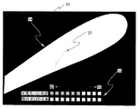
そして、内視鏡2の挿入部先端をジェットエンジンのブレード24の観察位置に配置された状態で蛍光探傷検査を開始するために、モード切替ボタン部17においてモード設定ボタンによりCPU13の制御モードを通常観察モードから蛍光観察モードに変更/設定する。この蛍光観察モードでは、CPU13は可視光量調節部11及び紫外光量調節部12をそれぞれ所定の駆動電圧を制御することで、図4に示すように、所定光量の可視光による検査対象物3であるブレード24の通常観察画像と、所定光量の紫外光により励起されたブレード24上の探傷対象である傷25からの蛍光観察画像とがリアルタイムに表示部20の同一画面上に表示される。
Then, in order to start the fluorescent flaw inspection with the distal end of the insertion portion of the
このときのインジケータ画像26は、図4に示すように、蛍光観察モードにおけるジェットエンジンブレード検査での、可視光LED光源6及び紫外光LED光源7のデフォルトの光量をアナログ的にレベル表示する。可視光LED光源6及び紫外光LED光源7のデフォルトの光量は、可視光量調節ボタン部15、紫外光調節ボタン部16をそれぞれ操作することで、個別に任意に増減できる。図5は、可視光量調節ボタン部15により可視光LED光源6の光量を最小にし、紫外光調節ボタン部16により紫外光LED光源7の光量を最大にした状態を示しており、ブレード24の形状は不明瞭になるが、傷25を強調して表示することができる。
As shown in FIG. 4, the
このように本実施例によれば、可視光による観察下で検査対象物3に内視鏡2の挿入部先端を導くと共に、内視鏡2の挿入部先端を検査対象物3の所定の位置に配置した後に、蛍光探傷検査を可視光よる通常観察画像及び紫外光による蛍光画像の2つの画像でリアルタイムに行うことができるので、簡単かつ確実に欠陥等の問題箇所である傷25の状態及び傷25の検査対象物3であるブレード24上の位置をリアルタイムで検査することができる。また、可視光及び紫外光を任意に増減することができるので、所望の明るさの通常観察画像及び蛍光画像で蛍光探傷検査を行うことが可能となる。さらに、モード切替ボタン部17の対象設定ボタンにより検査対象を設定することで、検査環境に応じた可視光量調節部11及び紫外光量調節部12のデフォルト調節値を設定することができるので、検査前の装置設定が容易になるといった効果もある。
As described above, according to the present embodiment, the distal end of the insertion portion of the
なお、可視光LED光源6及び紫外光LED光源7の光量をインジケータ画像26によりアナログ的に表示するとしたが、これに限らず、図6に示すように、可視光LED光源6及び紫外光LED光源7の光量を数値画像27によりデジタル的なレベルで表示するようにしてもよい。また、インジケータ画像26を検査対象物3の画像に重畳させて表示しているが、これに限らず、表示部20とは別体に、インジケータ画像26の表示専用の表示手段、例えばLCDや、インジケータ画像26に相当するLEDインジケータを設けても良い。
Although the light amounts of the visible light
また、図1に示したように、可視光LED光源6及び紫外光LED光源7を内視鏡2の挿入部先端内に配置するとしたが、これに限らず、図7に示すように、内視鏡2の挿入部内にライトガイド30を配置すると共に、可視光LED光源6及び紫外光LED光源7を装置本体4内に設け、可視光LED光源6及び紫外光LED光源7からの光をライトガイド30を介して検査対象物3に照射するように構成しても、図1の構成と同様に、可視光LED光源6及び紫外光LED光源7の光量を制御することで、同様な作用・効果が得られることはいうまでもない。
Further, as shown in FIG. 1, the visible light
さらに、本実施例では、可視光LED光源6及び紫外光LED光源7をそれぞれ1つから構成したが、これに限らず、図8に示すように、例えば可視光LED光源6a,6b及び紫外光LED光源7a,7bのようにそれぞれ2つ設け、図9に示すように左右に分離してそれぞれ配置してもよい。
Furthermore, in this embodiment, the visible LED
この場合、それぞれ4つのLED光源6a,6b及び7a,7bの光量を独立に制御することで、可視光LED光源6a,6bにより独立に光量が調節された可視光を左右よりブレード24を照射することでハレーションや影の影響を受けない全体像が通常観察画像として得られると共に、紫外光LED光源7a,7bにより独立に光量が調節された紫外光左右より照射することで傷25からの蛍光画像を立体的な画像として得ることが可能となる。
In this case, by independently controlling the light amounts of the four
なお、紫外光LED光源7a,7bが発光する紫外光を異なる波長とすることで、検査対象物3に塗布する蛍光剤を検査環境に応じて変えることが可能となり、塗布された蛍光剤に基づいた紫外光LED光源のみを駆動することで、本実施例と同様な作用・効果を得ることができる。
In addition, it becomes possible to change the fluorescent agent apply | coated to the test target object 3 according to a test | inspection environment by making the ultraviolet light which ultraviolet light
また、可視光LED光源及び紫外光LED光源の数は、図1及び図8に限定されず、任意に数だけぞれぞれ可視光LED光源及び紫外光LED光源を構成してもよい。 Moreover, the number of visible light LED light sources and ultraviolet light LED light sources is not limited to FIG.1 and FIG.8, You may comprise visible light LED light sources and ultraviolet light LED light sources arbitrarily, respectively.
また、実施例では、可視光LED光源6及び紫外光LED光源7から構成したが、これに限らず、図10に示すように、可視光LED光源6及び紫外光LED光源7の他に、赤外光LED光源50を設け、装置本体4の赤外光量調節部51により独立に、赤外光LED光源50の光量を調節することが可能に構成しても良い。
Moreover, in the Example, although comprised from the visible light
なお、本実施例では、可視光LED光源及び紫外光LED光源の光量は、可視光量調節ボタン部15、紫外光量調節ボタン部16により増減設定されるとしたが、これに限らず、予め可視光LED光源及び紫外光LED光源の光量の各比率を複数組、設定した光量比率設定テーブルをメモリ14に格納し、この光量比率設定テーブルに従って、可視光LED光源及び紫外光LED光源の光量を設定するようにしてもよい。
In this embodiment, the light amounts of the visible light LED light source and the ultraviolet light LED light source are set to increase / decrease by the visible light amount
複数組の可視光LED光源及び紫外光LED光源の光量の比率組の一例を以下に示す。 An example of the ratio set of the light amounts of a plurality of sets of visible LED light sources and ultraviolet LED light sources is shown below.
比率組1:可視光LED光源光量、紫外光LED光源光量)=(100%、0%)
比率組2:可視光LED光源光量、紫外光LED光源光量)=(70%、20%)
比率組3:可視光LED光源光量、紫外光LED光源光量)=(50%、50%)
比率組4:可視光LED光源光量、紫外光LED光源光量)=(30%、80%)
比率組5:可視光LED光源光量、紫外光LED光源光量)=(0%、100%)
上記各比率組を光量比率設定テーブルとして記憶し、可視光量調節ボタン部15、紫外光量調節ボタン部16に代わる図示しない光量選択ボタン等を用いて比率組を選択し、比率組に応じて可視光LED光源及び紫外光LED光源の光量を設定するようにしてもよい。
Ratio group 1: Visible LED light source light quantity, UV light LED light source light quantity) = (100%, 0%)
Ratio group 2: Visible light LED light source light quantity, UV light LED light source light quantity) = (70%, 20%)
Ratio group 3: Visible light LED light source light quantity, UV light LED light source light quantity) = (50%, 50%)
Ratio group 4: Visible light LED light source light quantity, UV light LED light source light quantity) = (30%, 80%)
Ratio group 5: Visible LED light source light amount, UV light LED light source light amount) = (0%, 100%)
Each ratio set is stored as a light quantity ratio setting table, and a ratio set is selected using a light quantity selection button (not shown) instead of the visible light quantity
本発明は、上述した実施例に限定されるものではなく、本発明の要旨を変えない範囲において、種々の変更、改変等が可能である。 The present invention is not limited to the above-described embodiments, and various changes and modifications can be made without departing from the scope of the present invention.
1…内視鏡装置
2…内視鏡
3…検査対象物
4…装置本体部
5…光源ユニット
6…可視光LED光源
7…紫外光LED光源
8…撮像部
9…電源部
10…光源用電源部
11…可視光量調節部
12…紫外光量調節部
13…CPU
14…メモリ
15…可視光量調節ボタン部
16…紫外光量調節ボタン部
17…モード切替ボタン部
18…信号処理部
19…スーパーインポーズ部
20…表示部
21…バッテリ
DESCRIPTION OF
DESCRIPTION OF
Claims (7)
前記検査対象物を照明するものであり、可視光を発光する可視光LED光源と、不可視光を発光する不可視光LED光源とを含む少なくとも2系統のLED光源手段と、
少なくとも前記可視光と前記不可視光とを同時照明しているときに各系統毎の前記LED光源の出射光量を独立して調節する光量調節手段と、
前記光量調節手段が前記LED光源の各系統毎に調節する調節値を示す調節値情報と、前記観察画像データとを表示する表示手段と
を有することを特徴とする内視鏡装置。 In an endoscope apparatus that generates observation image data of an inspection object based on an observation image captured by an imaging unit,
At least two LED light source means for illuminating the inspection object and including a visible LED light source that emits visible light and an invisible LED light source that emits invisible light ;
A light amount adjusting means for independently adjusting the emitted light amount of the LED light source for each system when simultaneously illuminating at least the visible light and the invisible light ;
An endoscope apparatus comprising: adjustment value information indicating an adjustment value to be adjusted for each system of the LED light source by the light amount adjustment means; and display means for displaying the observation image data.
前記光量調節手段は、前記調節値設定手段によって指示された前記調節値に基づいて各系統毎の前記LED光源の出射光量を調節し、
前記表示手段は、前記調節値設定手段によって指示された前記調節値を示す前記調節値情報と、前記調節値に基づいて前記光量調節手段によって調節された出射光量で撮像された前記観察画像データとを同一画面上に表示することを特徴とする請求項1に記載の内視鏡装置。 Adjustment value setting means for indicating the adjustment value ;
The light amount adjusting means adjusts the emitted light amount of the LED light source for each system based on the adjustment value instructed by the adjustment value setting means ,
The display means includes the adjustment value information indicating the adjustment value instructed by the adjustment value setting means , and the observation image data imaged with the emitted light quantity adjusted by the light quantity adjustment means based on the adjustment value. The endoscope apparatus according to claim 1, wherein: is displayed on the same screen.
Priority Applications (1)
| Application Number | Priority Date | Filing Date | Title |
|---|---|---|---|
| JP2005329370A JP4916160B2 (en) | 2005-11-14 | 2005-11-14 | Endoscope device |
Applications Claiming Priority (1)
| Application Number | Priority Date | Filing Date | Title |
|---|---|---|---|
| JP2005329370A JP4916160B2 (en) | 2005-11-14 | 2005-11-14 | Endoscope device |
Publications (3)
| Publication Number | Publication Date |
|---|---|
| JP2007139822A JP2007139822A (en) | 2007-06-07 |
| JP2007139822A5 JP2007139822A5 (en) | 2009-01-08 |
| JP4916160B2 true JP4916160B2 (en) | 2012-04-11 |
Family
ID=38202812
Family Applications (1)
| Application Number | Title | Priority Date | Filing Date |
|---|---|---|---|
| JP2005329370A Expired - Fee Related JP4916160B2 (en) | 2005-11-14 | 2005-11-14 | Endoscope device |
Country Status (1)
| Country | Link |
|---|---|
| JP (1) | JP4916160B2 (en) |
Families Citing this family (53)
| Publication number | Priority date | Publication date | Assignee | Title |
|---|---|---|---|---|
| JP5062414B2 (en) * | 2007-11-27 | 2012-10-31 | セイコーインスツル株式会社 | Inspection apparatus, inspection method, rolling bearing manufacturing apparatus, and rolling bearing manufacturing method |
| JP5767775B2 (en) | 2009-07-06 | 2015-08-19 | 富士フイルム株式会社 | Endoscope device |
| JP5364520B2 (en) * | 2009-09-24 | 2013-12-11 | 富士フイルム株式会社 | Endoscope apparatus and method for operating endoscope apparatus |
| JP2011147757A (en) * | 2009-09-29 | 2011-08-04 | Fujifilm Corp | Medical apparatus and endoscope apparatus |
| JP2011156339A (en) * | 2010-01-08 | 2011-08-18 | Fujifilm Corp | Medical apparatus and endoscope apparatus |
| JP2012016545A (en) * | 2010-07-09 | 2012-01-26 | Fujifilm Corp | Endoscope apparatus |
| JP5431294B2 (en) * | 2010-11-16 | 2014-03-05 | 富士フイルム株式会社 | Endoscope device |
| JP5631764B2 (en) * | 2011-01-25 | 2014-11-26 | 富士フイルム株式会社 | Endoscope system and operating method thereof |
| EP2689708B1 (en) | 2011-04-27 | 2016-10-19 | Olympus Corporation | Endoscopic apparatus and measurement method |
| JP5893264B2 (en) * | 2011-04-27 | 2016-03-23 | オリンパス株式会社 | Endoscope device |
| JP5830270B2 (en) | 2011-05-24 | 2015-12-09 | オリンパス株式会社 | Endoscope apparatus and measuring method |
| JP5846763B2 (en) | 2011-05-24 | 2016-01-20 | オリンパス株式会社 | Endoscope device |
| JP5450527B2 (en) | 2011-08-10 | 2014-03-26 | 富士フイルム株式会社 | Endoscope device |
| US11871901B2 (en) | 2012-05-20 | 2024-01-16 | Cilag Gmbh International | Method for situational awareness for surgical network or surgical network connected device capable of adjusting function based on a sensed situation or usage |
| JP2014121630A (en) * | 2014-02-10 | 2014-07-03 | Fujifilm Corp | Endoscope device |
| JP6039606B2 (en) | 2014-06-24 | 2016-12-07 | 富士フイルム株式会社 | Endoscope system, light source device, operation method of endoscope system, and operation method of light source device |
| JP5922209B2 (en) * | 2014-11-10 | 2016-05-24 | 富士フイルム株式会社 | Endoscope device |
| JP2015091351A (en) * | 2014-12-24 | 2015-05-14 | 富士フイルム株式会社 | Endoscope device |
| JP2016105824A (en) * | 2016-02-08 | 2016-06-16 | 富士フイルム株式会社 | Endoscope apparatus |
| JP6155367B2 (en) * | 2016-06-17 | 2017-06-28 | 富士フイルム株式会社 | Endoscope device |
| JP6550420B2 (en) * | 2017-06-02 | 2019-07-24 | 富士フイルム株式会社 | Endoscope device |
| JP6379260B2 (en) * | 2017-07-04 | 2018-08-22 | 富士フイルム株式会社 | Endoscope device |
| JP6353962B2 (en) * | 2017-07-12 | 2018-07-04 | 富士フイルム株式会社 | Endoscope device |
| US11911045B2 (en) | 2017-10-30 | 2024-02-27 | Cllag GmbH International | Method for operating a powered articulating multi-clip applier |
| US10980560B2 (en) | 2017-10-30 | 2021-04-20 | Ethicon Llc | Surgical instrument systems comprising feedback mechanisms |
| US11801098B2 (en) | 2017-10-30 | 2023-10-31 | Cilag Gmbh International | Method of hub communication with surgical instrument systems |
| US11771487B2 (en) | 2017-12-28 | 2023-10-03 | Cilag Gmbh International | Mechanisms for controlling different electromechanical systems of an electrosurgical instrument |
| US20190200906A1 (en) * | 2017-12-28 | 2019-07-04 | Ethicon Llc | Dual cmos array imaging |
| US11818052B2 (en) | 2017-12-28 | 2023-11-14 | Cilag Gmbh International | Surgical network determination of prioritization of communication, interaction, or processing based on system or device needs |
| US11864728B2 (en) | 2017-12-28 | 2024-01-09 | Cilag Gmbh International | Characterization of tissue irregularities through the use of mono-chromatic light refractivity |
| US11896443B2 (en) | 2017-12-28 | 2024-02-13 | Cilag Gmbh International | Control of a surgical system through a surgical barrier |
| US11744604B2 (en) | 2017-12-28 | 2023-09-05 | Cilag Gmbh International | Surgical instrument with a hardware-only control circuit |
| US10758310B2 (en) | 2017-12-28 | 2020-09-01 | Ethicon Llc | Wireless pairing of a surgical device with another device within a sterile surgical field based on the usage and situational awareness of devices |
| US11132462B2 (en) | 2017-12-28 | 2021-09-28 | Cilag Gmbh International | Data stripping method to interrogate patient records and create anonymized record |
| US11832899B2 (en) | 2017-12-28 | 2023-12-05 | Cilag Gmbh International | Surgical systems with autonomously adjustable control programs |
| US11844579B2 (en) | 2017-12-28 | 2023-12-19 | Cilag Gmbh International | Adjustments based on airborne particle properties |
| US11857152B2 (en) | 2017-12-28 | 2024-01-02 | Cilag Gmbh International | Surgical hub spatial awareness to determine devices in operating theater |
| US11969142B2 (en) | 2017-12-28 | 2024-04-30 | Cilag Gmbh International | Method of compressing tissue within a stapling device and simultaneously displaying the location of the tissue within the jaws |
| US11389164B2 (en) | 2017-12-28 | 2022-07-19 | Cilag Gmbh International | Method of using reinforced flexible circuits with multiple sensors to optimize performance of radio frequency devices |
| US11786251B2 (en) | 2017-12-28 | 2023-10-17 | Cilag Gmbh International | Method for adaptive control schemes for surgical network control and interaction |
| US11013563B2 (en) | 2017-12-28 | 2021-05-25 | Ethicon Llc | Drive arrangements for robot-assisted surgical platforms |
| US11109866B2 (en) | 2017-12-28 | 2021-09-07 | Cilag Gmbh International | Method for circular stapler control algorithm adjustment based on situational awareness |
| US11969216B2 (en) | 2017-12-28 | 2024-04-30 | Cilag Gmbh International | Surgical network recommendations from real time analysis of procedure variables against a baseline highlighting differences from the optimal solution |
| US11672605B2 (en) | 2017-12-28 | 2023-06-13 | Cilag Gmbh International | Sterile field interactive control displays |
| US11166772B2 (en) | 2017-12-28 | 2021-11-09 | Cilag Gmbh International | Surgical hub coordination of control and communication of operating room devices |
| US11896322B2 (en) | 2017-12-28 | 2024-02-13 | Cilag Gmbh International | Sensing the patient position and contact utilizing the mono-polar return pad electrode to provide situational awareness to the hub |
| US11259830B2 (en) | 2018-03-08 | 2022-03-01 | Cilag Gmbh International | Methods for controlling temperature in ultrasonic device |
| US11399858B2 (en) | 2018-03-08 | 2022-08-02 | Cilag Gmbh International | Application of smart blade technology |
| US11090047B2 (en) | 2018-03-28 | 2021-08-17 | Cilag Gmbh International | Surgical instrument comprising an adaptive control system |
| US11298130B2 (en) | 2019-02-19 | 2022-04-12 | Cilag Gmbh International | Staple cartridge retainer with frangible authentication key |
| JP7208876B2 (en) * | 2019-09-11 | 2023-01-19 | 富士フイルム株式会社 | Endoscope system and its operating method |
| JP2020078667A (en) * | 2020-02-28 | 2020-05-28 | 富士フイルム株式会社 | Endoscope apparatus |
| JP2022031393A (en) * | 2020-02-28 | 2022-02-18 | 富士フイルム株式会社 | Endoscope apparatus |
Family Cites Families (8)
| Publication number | Priority date | Publication date | Assignee | Title |
|---|---|---|---|---|
| JPS63240191A (en) * | 1987-03-27 | 1988-10-05 | Toshiba Corp | Electron endoscope device |
| JP3868050B2 (en) * | 1997-02-06 | 2007-01-17 | オリンパス株式会社 | Endoscope |
| JPH11225952A (en) * | 1998-02-12 | 1999-08-24 | Olympus Optical Co Ltd | Endoscope device |
| JP4454801B2 (en) * | 2000-06-19 | 2010-04-21 | オリンパス株式会社 | Endoscope |
| JP2002112959A (en) * | 2000-10-06 | 2002-04-16 | Asahi Optical Co Ltd | Lighting device for electronic endoscope |
| JP2002301027A (en) * | 2001-04-04 | 2002-10-15 | Asahi Optical Co Ltd | Portable endoscope system |
| JP2005156651A (en) * | 2003-11-21 | 2005-06-16 | Olympus Corp | Scanning optical microscope |
| JP4507596B2 (en) * | 2003-12-26 | 2010-07-21 | 株式会社ニコン | Laser modulation confocal microscope system |
-
2005
- 2005-11-14 JP JP2005329370A patent/JP4916160B2/en not_active Expired - Fee Related
Also Published As
| Publication number | Publication date |
|---|---|
| JP2007139822A (en) | 2007-06-07 |
Similar Documents
| Publication | Publication Date | Title |
|---|---|---|
| JP4916160B2 (en) | Endoscope device | |
| US10898110B2 (en) | Endoscope apparatus and measuring method | |
| KR100954475B1 (en) | Endoscope | |
| US7907169B2 (en) | Electronic endoscope system for fluorescence observation | |
| US7811229B2 (en) | Electronic endoscope system for fluorescence observation | |
| US7632227B2 (en) | Electronic endoscope system | |
| US7625336B2 (en) | Electronic endoscope system with functionally alterable operable members | |
| WO2012161246A1 (en) | Endoscope and image acquisition method | |
| JP5959768B2 (en) | Endoscope system | |
| JP2010113312A (en) | Endoscope apparatus and endoscope processor | |
| JP2006223850A (en) | Electronic endoscope system | |
| JP2008032645A (en) | Magnifying observation device | |
| JPWO2019225074A1 (en) | Endoscope system, endoscope processor, endoscope system control method, and program | |
| JPH1038539A (en) | Wafer shape recognizing device | |
| JP4459709B2 (en) | Fluorescence observation endoscope device | |
| JP2008125989A (en) | Endoscope point beam illumination position adjusting system | |
| JP2011149814A (en) | Coating inspection device and coating inspection method | |
| US8132951B2 (en) | Endoscope system | |
| WO2016098449A1 (en) | Endoscope, and endoscope system including said endoscope | |
| JP4654351B2 (en) | Electronic endoscope system and electronic endoscope | |
| WO2016098444A1 (en) | Endoscope and endoscope system including endoscope | |
| WO2018220930A1 (en) | Image processing device | |
| JP2005168828A (en) | Autologous fluorescence electronic endoscope apparatus | |
| JPH09540A (en) | Fluorescent image diagnostic device for operation | |
| KR20180070133A (en) | Electronic endoscope system |
Legal Events
| Date | Code | Title | Description |
|---|---|---|---|
| A521 | Written amendment |
Free format text: JAPANESE INTERMEDIATE CODE: A523 Effective date: 20081113 |
|
| A621 | Written request for application examination |
Free format text: JAPANESE INTERMEDIATE CODE: A621 Effective date: 20081113 |
|
| A977 | Report on retrieval |
Free format text: JAPANESE INTERMEDIATE CODE: A971007 Effective date: 20111013 |
|
| A131 | Notification of reasons for refusal |
Free format text: JAPANESE INTERMEDIATE CODE: A131 Effective date: 20111018 |
|
| A521 | Written amendment |
Free format text: JAPANESE INTERMEDIATE CODE: A523 Effective date: 20111124 |
|
| TRDD | Decision of grant or rejection written | ||
| A01 | Written decision to grant a patent or to grant a registration (utility model) |
Free format text: JAPANESE INTERMEDIATE CODE: A01 Effective date: 20120117 |
|
| A01 | Written decision to grant a patent or to grant a registration (utility model) |
Free format text: JAPANESE INTERMEDIATE CODE: A01 |
|
| A61 | First payment of annual fees (during grant procedure) |
Free format text: JAPANESE INTERMEDIATE CODE: A61 Effective date: 20120124 |
|
| FPAY | Renewal fee payment (event date is renewal date of database) |
Free format text: PAYMENT UNTIL: 20150203 Year of fee payment: 3 |
|
| R151 | Written notification of patent or utility model registration |
Ref document number: 4916160 Country of ref document: JP Free format text: JAPANESE INTERMEDIATE CODE: R151 |
|
| FPAY | Renewal fee payment (event date is renewal date of database) |
Free format text: PAYMENT UNTIL: 20150203 Year of fee payment: 3 |
|
| S531 | Written request for registration of change of domicile |
Free format text: JAPANESE INTERMEDIATE CODE: R313531 |
|
| R350 | Written notification of registration of transfer |
Free format text: JAPANESE INTERMEDIATE CODE: R350 |
|
| R250 | Receipt of annual fees |
Free format text: JAPANESE INTERMEDIATE CODE: R250 |
|
| LAPS | Cancellation because of no payment of annual fees |