JP5820210B2 - IMAGING DEVICE AND IMAGING DEVICE CONTROL METHOD - Google Patents
IMAGING DEVICE AND IMAGING DEVICE CONTROL METHOD Download PDFInfo
- Publication number
- JP5820210B2 JP5820210B2 JP2011202337A JP2011202337A JP5820210B2 JP 5820210 B2 JP5820210 B2 JP 5820210B2 JP 2011202337 A JP2011202337 A JP 2011202337A JP 2011202337 A JP2011202337 A JP 2011202337A JP 5820210 B2 JP5820210 B2 JP 5820210B2
- Authority
- JP
- Japan
- Prior art keywords
- subject
- detected
- imaging
- detection
- image
- Prior art date
- Legal status (The legal status is an assumption and is not a legal conclusion. Google has not performed a legal analysis and makes no representation as to the accuracy of the status listed.)
- Expired - Fee Related
Links
Images


Landscapes
- Stereoscopic And Panoramic Photography (AREA)
- Accessories Of Cameras (AREA)
- Studio Circuits (AREA)
- Studio Devices (AREA)
Description
本発明は、撮像装置に関し、特に、移動機構を持ち、撮影方向を移動させることが可能な撮像装置に関するものである。 The present invention relates to an imaging apparatus, and more particularly to an imaging apparatus having a moving mechanism and capable of moving a shooting direction.
近年、ネットワークや専用線を介して、遠隔操作によりカメラを制御し、映像を監視するネットワークカメラが知られている。ネットワークカメラは多機能化しており、AF(自動合焦)や電動ズーム可能なレンズを搭載したものや、パン(水平方向回転)、チルト(垂直方向回転)機構を有し、撮影方向を移動できるものもある。 2. Description of the Related Art In recent years, network cameras that monitor a video by controlling the camera by remote operation via a network or a dedicated line are known. The network camera is multi-functional and has a lens equipped with AF (automatic focus) and electric zoom, pan (horizontal rotation), and tilt (vertical rotation) mechanism, and can move the shooting direction. There are also things.
パン・チルト(以下PTと略す)機構を有したネットワークカメラには、プリセット撮影機能が備えられているものが多い。プリセット撮影では、事前に任意の撮影方向を設定しておくことで、その設定された撮影方向に自動で移動を行い撮影することができる。また、監視エリアにおけるプライバシーや機密情報の保護のため、撮影画像の中の任意の箇所を隠すことができるマスキング機能を有したものがある。また、画像解析により監視エリアにおける物の持ち去りや置き去り等の異常をカメラ自身が検出するインテリジェント機能を有していたものもある。 Many network cameras having a pan / tilt (hereinafter abbreviated as PT) mechanism have a preset shooting function. In preset shooting, by setting an arbitrary shooting direction in advance, it is possible to automatically move in the set shooting direction and perform shooting. In addition, there is a masking function that can hide an arbitrary portion in a captured image in order to protect privacy and confidential information in a monitoring area. Some cameras have an intelligent function for detecting abnormalities such as removal or leaving of objects in the monitoring area by image analysis.
これらの機能を利用する際の設定、例えばプリセット撮影機能でのプリセット位置の設定においては、プリセット位置として登録したい撮影方向の設定を行う。撮影方向を操作する方法としては、パン位置、チルト位置を示したスクロールバーを用いた操作方法や、撮影範囲全域を一つの広域画像として示したパノラマ画像を利用した操作方法等が一般的である。 In the setting when using these functions, for example, the setting of the preset position in the preset shooting function, the shooting direction to be registered as the preset position is set. As a method for operating the shooting direction, an operation method using a scroll bar indicating a pan position and a tilt position, an operation method using a panoramic image showing the entire shooting range as one wide area image, and the like are common. .
パノラマ画像を利用した操作方法では、まずPT機構の可動範囲内を順次移動して撮影を行った後、各方向にて撮影した画像を合成し、撮影範囲全域を一つの広域画像として示したパノラマ画像を生成する。そのパノラマ画像の中で撮影箇所を指定し、撮影方向を操作する。例えばパノラマ画像中に撮影画角を示した枠を表示し、この枠を任意の位置、画角に設定することで撮影方向を操作する。 In the operation method using the panorama image, first, the images are taken by sequentially moving within the movable range of the PT mechanism, and then the images taken in each direction are combined, and the panorama showing the entire shooting range as one wide-area image. Generate an image. The shooting location is designated in the panorama image, and the shooting direction is operated. For example, a frame indicating the shooting angle of view is displayed in the panoramic image, and the shooting direction is operated by setting the frame to an arbitrary position and angle of view.
これらの方法における課題として、スクロールバーを用いた方法では、操作にある程度慣れが必要であり、また撮影したい被写体を探しながら操作する必要があるため、撮影したい方向までカメラを導くのに時間を要してしまうことがあった。またパノラマ画像を利用した方法では、撮影位置を指定することで瞬時に撮影方向を移動させることはできるが、パノラマ画像の中でどこに何が映っているのかといった被写体の位置を認識しづらいことがあった。さらには、ユーザが注視の必要性を意識して設定を行った撮影箇所以外にも、ユーザが気付いていない注視が必要な撮影箇所がある場合もあり、注視を要する撮影箇所が抜けてしまう可能性もあった。 As a problem with these methods, the method using the scroll bar requires some experience in operation, and it is necessary to operate while searching for the subject to be photographed, so it takes time to guide the camera to the direction to be photographed. I had to do it. In the method using panoramic images, it is possible to move the shooting direction instantly by specifying the shooting position, but it is difficult to recognize the position of the subject such as what is shown in the panoramic image. there were. Furthermore, in addition to the shooting locations that the user has set with awareness of the need for gaze, there may be shooting locations that require gaze that the user is not aware of, and the shooting locations that require gaze may be missed. There was also sex.
パノラマ画像を利用した撮像装置として特許文献1は、生成したパノラマ画像を構成する一つの画像と先に撮像された同一撮影方向の画像との間で差異を順次検出し、検出した結果に基づき生成したパノラマ画像と共に所定情報を表示することを開示している。
As an imaging device using a panoramic image,
また、特許文献2には次のようなことが開示されている。即ちプリセット撮影機能を有した撮像装置において、登録されたプリセット位置にて撮影した画像のサムネイル画像を表示し、サムネイル画像を選択することで、該選択サムネイル画像に対応するプリセット位置へ撮像装置の姿勢を制御する方法を開示している。
しかしながら、上述の特許文献1に開示された従来技術では、撮影画像の差分により被写体の変化は検出するが、撮影範囲の被写体位置の認識を容易化するものではない。また、複数回パノラマ撮影を行った画像同士の差分検出では、比較する画像の撮影された時間差が大きいため画像の変化も大きくなり、誤検出が生じる可能性が高い。
However, in the conventional technique disclosed in
また、特許文献2に開示された従来技術では、登録したプリセット位置のサムネイル画像表示により、登録したプリセット位置の撮影方向を把握しやすくするもので、プリセット位置登録時の設定を容易化するものではない。
Further, in the prior art disclosed in
本発明はこのような問題に鑑みてなされたものであり、撮影方向を移動することができる撮像装置において、撮影範囲内の被写体位置の認識を容易に行う為の技術を提供することを目的とする。 The present invention has been made in view of such problems, and an object of the present invention is to provide a technique for easily recognizing a subject position within a shooting range in an imaging apparatus capable of moving the shooting direction. To do.
本発明の目的を達成するために、例えば、本発明の撮像装置は、撮像方向を変化させながら撮像を行うことで、複数の撮像方向における撮像画像を取得する取得手段と、
前記取得手段が取得した撮像画像から被写体を検出する検出処理を行う検出手段と、
前記取得手段が取得した複数の撮像画像を連結してパノラマ画像を生成し、前記検出手段によって検出された被写体を報知するための情報を、前記パノラマ画像上に合成して出力する出力手段と
を備え、
前記検出手段は、規定の被写体が検出された撮像画像に対しては第1の時間の前記検出処理を行い、該規定の被写体が検出されなかった撮像画像に対しては該第1の時間よりも短い第2の時間の前記検出処理を行う
ことを特徴とする。
In order to achieve the object of the present invention, for example, an imaging apparatus of the present invention includes an acquisition unit that acquires captured images in a plurality of imaging directions by performing imaging while changing the imaging direction;
Detection means for performing detection processing for detecting a subject from the captured image acquired by the acquisition means;
Output means for connecting a plurality of captured images acquired by the acquisition means to generate a panoramic image, and combining and outputting information for notifying the subject detected by the detection means on the panoramic image; Prepared ,
The detection means performs the detection process for a first time for a captured image in which a specified subject is detected, and for the captured image in which the specified subject is not detected, from the first time. The detection process is performed for a short second time .
本発明の構成によれば、撮影方向を移動することができる撮像装置において、撮影範囲内の被写体位置の認識を容易に行うことができる。 According to the configuration of the present invention, it is possible to easily recognize the subject position within the shooting range in the imaging apparatus capable of moving the shooting direction.
以下、添付図面を参照し、本発明の好適な実施形態について説明する。なお、以下説明する実施形態は、本発明を具体的に実施した場合の一例を示すもので、特許請求の範囲に記載の構成の具体的な実施例の1つである。 Preferred embodiments of the present invention will be described below with reference to the accompanying drawings. The embodiment described below shows an example when the present invention is specifically implemented, and is one of the specific examples of the configurations described in the claims.
[第1の実施形態]
先ず、本実施形態に係るネットワークカメラシステムの構成例について、図1を用いて説明する。図1に示す如く、本実施形態に係るネットワークカメラシステムは、撮像装置としてのネットワークカメラ100と、情報処理装置としてのクライアント装置120と、を有している。そして、ネットワークカメラ100とクライアント装置120とは、LANやインターネットなどのネットワーク110に接続されており、互いにデータ通信が可能な状態となっている。もちろん、このネットワーク110は有線、無線の何れであってもよい。また、ネットワークカメラ100とクライアント装置120との間は2種類以上のネットワークを介してもよいし、ネットワークカメラ100とクライアント装置120との間に1以上の装置を介してもよい。即ち、ネットワークカメラ100とクライアント装置120とが互いにデータ通信を行うことができるのであれば、ネットワークカメラ100とクライアント装置120との間のネットワーク構成は特定のネットワーク構成に限るものではない。
[First Embodiment]
First, a configuration example of the network camera system according to the present embodiment will be described with reference to FIG. As shown in FIG. 1, the network camera system according to the present embodiment includes a
先ず、ネットワークカメラ100の構成例について説明する。なお、ネットワークカメラ100の構成について、図1には以下の説明で使用する主要な構成しか示していない。
First, a configuration example of the
撮像部101は、レンズ及び撮像素子から構成され、被写体を含む外界の光を電気信号に変換し、変換した電気信号を画像信号として画像処理部102に転送する。
The
画像処理部102は、撮像部101から順次送出される各フレームの画像信号に対して適当な画像処理を施すことで、ディジタルデータとしての撮像画像を生成する。
The
システム制御部103は、ネットワークカメラ100を構成する各部の動作制御を行うと共に、ネットワーク110を介したクライアント装置120とのデータ通信(データの送受信)を制御する。
The
例えば、システム制御部103は、画像処理部122から順次送出される各フレームの撮像画像を順次、ネットワーク110を介してクライアント装置120に対して送信する。
For example, the
また、システム制御部103は、ネットワーク110を介してクライアント装置120から送信された各種のコマンドを受信すると、該受信したコマンドに応じた処理も実行する。
Further, when the
例えば、クライアント装置120からカメラ制御コマンドを受信すると、システム制御部103は、ネットワークカメラ100の撮像条件の設定や、撮像方向におけるパン角及びチルト角の制御を行う。より詳しくは、システム制御部103は、カメラ制御コマンドを受信すると、レンズ制御コマンドをレンズ制御部105に送出する。これによりレンズ制御部105は、レンズ制御コマンドに従ってレンズ駆動部104を制御することで、撮像部101の画角などを制御する。またシステム制御部103は、カメラ制御コマンドを受信すると、PT動作コマンドをパンチルト制御部107に送出する。これによりパンチルト制御部107は、PT動作コマンドに従ってパン駆動部106やチルト駆動部108を制御することで、撮像部101のパン角及びチルト角を制御する。
For example, when a camera control command is received from the
また例えば、クライアント装置120から被写体位置解析コマンドを受信すると、システム制御部103は、後述する被写体位置解析処理を実行する。この被写体位置解析処理の詳細については後述する。
For example, when a subject position analysis command is received from the
レンズ駆動部104は、フォーカスレンズ及びズームレンズの駆動系及びその駆動源のモータにより構成され、その動作はレンズ制御部105によりレンズ制御コマンドに従って制御される。
The
パン駆動部106は、撮像部101のパン角を変更する為のメカ駆動系及び駆動源のモータにより構成され、その動作はパンチルト制御部107によりPT動作コマンドに従って制御される。
The
チルト駆動部108は、撮像部101のチルト角を変更する為のメカ駆動系及び駆動源のモータにより構成され、その動作はパンチルト制御部107によりPT動作コマンドに従って制御される。
The
記憶装置109は、後述する各処理を実行する際に一時的に若しくは恒久的に情報を格納しておくためのものである。例えば、記憶装置109には、後述するプリセット撮影機能におけるプリセット位置や被写体位置解析処理におけるパノラマ画像、解析結果、被写体ライブラリ等を記憶する。
The
次に、クライアント装置120の構成例について説明する。
Next, a configuration example of the
ネットワーク処理部121は、ネットワーク110を介してネットワークカメラ100とのデータの送受信を行う。例えば、ネットワークカメラ100からネットワーク110を介して撮像画像等の情報が送信された場合、ネットワーク処理部121は、この情報を受信して画像処理部122に転送する。また、ネットワーク処理部121は、カメラ制御UI処理部124から各種のコマンドを受けると、このコマンドをネットワーク110を介してネットワークカメラ100に送信する。
The
画像処理部122は、ネットワーク処理部121から撮像画像を受けると、この撮像画像に対して各種の画像処理を行った後、画像処理済みの撮像画像を表示装置123に送出する。これにより表示装置123の表示画面上にはこの画像処理済みの撮像画像が表示される。
Upon receiving the captured image from the
表示装置123は、CRTや液晶画面などにより構成されており、画像処理部122から受けた撮像画像や、後述する様々なUI(ユーザインターフェース)等、様々な情報を表示する。
The
カメラ制御UI処理部124は、ネットワークカメラ100の撮影条件の設定やパン角やチルト角等を指示するとともに、後述するプリセット位置の設定や被写体解析処理などのUIを表示装置123の表示画面上に表示させる。
The camera control
ユーザは、キーボードやマウスなどにより構成されている入力装置125を操作することで、このUIを操作することができると共に、各種のコマンドを入力することができる。
The user can operate the UI and input various commands by operating the
このように、クライアント装置120は、ネットワークカメラ100からネットワーク110を介して送信された撮像画像を取得することができると共に、ネットワーク110を介してネットワークカメラ100を制御することができる。
As described above, the
次に、パン角及びチルト角が制御可能なネットワークカメラ100の機構例を図2に示す。図2(A)はネットワークカメラ100の上面図、図2(B)はネットワークカメラ100の側面図である。
Next, FIG. 2 shows a mechanism example of the
パンの回転部はボトムケース201とターンテーブル202とで構成され、パン回転軸206を中心にターンテーブル202が水平面内で回転する。カメラヘッド204a、カメラヘッド204bは、パン回転した際のカメラヘッド204(レンズ205付き)の動きを示す。
The rotating part of the pan is composed of a
チルトの回転部はカメラヘッド支柱203とカメラヘッド204で構成され、チルト回転軸207を中心にカメラヘッド204が垂直方向に回転する。カメラヘッド204c、カメラヘッド204dは、チルト回転した際のカメラヘッド204の動きを示す。
The tilt rotation unit includes a
このように、カメラヘッドを水平方向及び垂直方向に回転移動させることで、撮影方向を変えることができ、これにより、広範囲を撮影することができる。 Thus, by rotating and moving the camera head in the horizontal direction and the vertical direction, the shooting direction can be changed, and thus a wide range can be shot.
本実施形態におけるネットワークカメラ100は、事前に任意の撮像方向を設定しておくことで、その設定された撮像方向に自動で移動を行うことができるプリセット撮影機能を有している。そして、プリセット撮影機能におけるプリセット位置を設定する際には、事前に撮影範囲内の被写体位置の認識を容易化するための被写体位置解析処理を行うことができる。
The
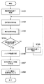
次に、クライアント装置120から被写体位置解析コマンドを受信した場合に、ネットワークカメラ100が行う処理について、同処理のフローチャートを示す図4を用いて説明する。
Next, processing performed by the
ステップS101でシステム制御部103は、撮像部101の撮像方向のパン角及びチルト角を規定範囲内で変化させながら撮像を行うための最初のパン角及びチルト角に撮像部101の姿勢を移動させるべく、パンチルト制御部107を制御する。
In step S101, the
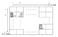
ステップS101で行う処理について、図3(A)を用いて説明する。図3(A)において太線Aで示す枠が、撮像部101が(現在設定されている画角で)撮像可能な撮像範囲である。本実施形態では、この撮像部101のパン角及びチルト角を変更させながら撮像を行うことで、点線Bで示す枠内の撮像範囲を撮像して、この撮像範囲内の撮像画像であるパノラマ画像を生成する。
The process performed in step S101 will be described with reference to FIG. A frame indicated by a thick line A in FIG. 3A is an imaging range in which the
より詳しくは、パン方向については各撮像位置(パン位置)1〜mで撮像が行えるように、パン角を変更する(パン位置pで撮像を行った後にパン角を変更してパン位置(p+1)で撮像を行うことを繰り返す)。チルト方向については各撮像位置(チルト位置)1〜nで撮像が行えるように、チルト角を変更する(チルト位置qで撮像を行った後にチルト角を変更してチルト位置(q+1)で撮像を行うことを繰り返す)。このように、m個のパン位置とn個のチルト位置の組み合わせ(m×n)個の撮像位置(撮像方向)で撮像を行うことで、点線Bで示す枠内の撮像範囲の撮像(パノラマ画像の撮像)を実現することができる。 More specifically, in the pan direction, the pan angle is changed so that the image can be picked up at each image pickup position (pan position) 1 to m (the pan angle is changed after the image pickup at the pan position p and the pan position (p + 1)). ) To repeat the imaging). As for the tilt direction, the tilt angle is changed so that imaging can be performed at each imaging position (tilt position) 1 to n (after imaging at the tilt position q, the tilt angle is changed and imaging is performed at the tilt position (q + 1). Repeat what you do). In this manner, by imaging at a combination (m × n) imaging positions (imaging directions) of m pan positions and n tilt positions, imaging of the imaging range within the frame indicated by the dotted line B (panorama) Image pickup) can be realized.
本実施形態では、点線Bで示す枠内の撮像範囲を撮像するために、次のようにして撮像部101のパン角及びチルト角を制御する。パン位置をP、チルト位置をT、撮像位置を(P,T)とすると、先ず(1,1)の撮像位置(開始位置)で撮像を行い、その後、パン角を変更しながら、(2,1)、(3,1)、…、(m、1)の各撮像位置で撮像を行う。そしてその後、撮像位置(m、2)で撮像を行うべくチルト角を変更する。そして、撮像位置(m、2)で撮像を行った後、パン角を変更しながら、(m−1,2)、(m−2,2)、…、(1、2)の各撮像位置で撮像を行う。そしてその後、撮像位置(1、3)で撮像を行うべくチルト角を変更する。そしてその後、(2,3)、(3,3)、…、(m、3)(m、4)、(m−1,4)、(m−2,4)、…、(1、4)のようにジグザグに移動していき、チルト位置1〜nにおいて、パン位置1〜mにおける撮像を行う。
In the present embodiment, in order to capture the imaging range within the frame indicated by the dotted line B, the pan angle and tilt angle of the
然るにステップS101では、システム制御部103は、撮像部101のパン角及びチルト角を、上記開始位置への撮像方向のパン角及びチルト角に変更すべく、パンチルト制御部107を制御する。これによりパンチルト制御部107は、撮像部101のパン角及びチルト角が、上記開始位置への撮像方向のパン角及びチルト角となるように、パン駆動部106及びチルト駆動部108を制御する。
However, in step S101, the
次に、ステップS102では、システム制御部103は、現在のパン角及びチルト角で撮像部101が撮像した撮像画像を画像処理部102から取得し、該取得した撮像画像中に映っている被写体の種別を識別する。
Next, in step S102, the
例えば、先ず、撮像画像から被写体の特徴量を抽出する。この特徴量は、例えば、撮像画像中のエッジである。撮像画像中の不連続となっている部分、例えば隣り合う画素の輝度値が大きく変化する部分をエッジとして抽出し、このエッジを境界線として撮像画像中の連続領域を抽出する。 For example, first, the feature amount of the subject is extracted from the captured image. This feature amount is, for example, an edge in the captured image. A discontinuous portion in the captured image, for example, a portion where the luminance value of adjacent pixels changes greatly is extracted as an edge, and a continuous region in the captured image is extracted using this edge as a boundary line.
そして、「ドア」、「窓」、「人」等のそれぞれ異なる種別の被写体の特徴量を保持するデータベース(被写体ライブラリ)を参照し、データベースに登録されているそれぞれの被写体の特徴量と、撮像画像から抽出した特徴量とのパターンマッチングを行う。パターンマッチングでは、データベースに登録されているそれぞれの被写体の特徴量と、撮像画像から抽出した特徴量との相関を評価する。そして、撮像画像から抽出した特徴量との相関評価値が最も高い特徴量の被写体の種別を、撮像画像中の被写体の種別として特定する。もちろん、撮像画像中の被写体の種別の識別方法はこれに限るものではなく、他の技術を用いてもよい。 Then, referring to a database (subject library) that holds feature amounts of different types of subjects such as “doors”, “windows”, and “people”, the feature amounts of each subject registered in the database and imaging Pattern matching with the feature amount extracted from the image is performed. In pattern matching, the correlation between the feature amount of each subject registered in the database and the feature amount extracted from the captured image is evaluated. Then, the type of the subject having the feature value having the highest correlation evaluation value with the feature amount extracted from the captured image is specified as the type of the subject in the captured image. Of course, the method for identifying the type of subject in the captured image is not limited to this, and other techniques may be used.
このとき、ユーザがデータベース中の各種被写体の中から検出を必要とする被写体を選択し、選択された被写体のみ検出処理を行うようにしてもよい。これにより、必要のない処理を省くことができ、処理時間を短縮することができる。 At this time, the user may select a subject that needs to be detected from various subjects in the database, and only the selected subject may be detected. Thereby, unnecessary processing can be omitted, and processing time can be shortened.
ステップS103では、システム制御部103は、現在のパン角及びチルト角で撮像部101が撮像した撮像画像を画像処理部102から取得し、該取得した撮像画像中に映っている動体としての被写体の種別を識別する。ステップS103における処理の詳細を、図5を用いて説明する。
In step S103, the
ステップS301では、システム制御部103は、画像処理部102を介して順次送出される複数枚の撮像画像の差分(フレーム間差分)を求め、求めたフレーム間差分から、動体としての被写体が映っているであろう部分(差分部)を検出する。ステップS302では、システム制御部103は、上記差分部の特徴量を抽出する。
In step S301, the
ステップS303では、システム制御部103は、ステップS302で抽出した特徴量を用いて上記パターンマッチングにより、ステップS301で検出した差分部における被写体の種別を特定する。
In step S303, the
ステップS304では、システム制御部103は、ステップS102の処理を開始してから所定時間が経過したか否かを判断する。この判断の結果、経過している場合は、処理はステップS104に進み、経過していない場合は、処理はステップS301に戻る。この所定時間は、被写体を検出するために、撮像画像を監視して検出処理を継続する時間であり、ユーザにより設定できるようにしてもかまわない。
In step S304, the
ステップS104では、システム制御部103は、最終撮像位置での撮像が完了したか否か(図3(A)の例では、点線Bの枠内の各撮像位置について撮像が完了したか否か)を判断する。この判断の結果、完了した場合は処理はステップS106に進み、完了していない場合は、処理はステップS105に進む。
In step S104, the
ステップS105では、システム制御部103は、撮像部101のパン角及びチルト角を、次の撮像位置への撮像方向のパン角及びチルト角に変更すべく、パンチルト制御部107を制御する。これによりパンチルト制御部107は、撮像部101のパン角及びチルト角が、次の撮像位置への撮像方向のパン角及びチルト角となるように、パン駆動部106及びチルト駆動部108を制御する。
In step S105, the
一方、処理がステップS106に進んだ時点で、点線Bの枠内の各撮像位置における撮像は完了しているので、ステップS106でシステム制御部103は、各撮像位置で撮像した撮像画像を連結することで、点線Bの枠内の画像、即ちパノラマ画像を生成する。
On the other hand, since the imaging at each imaging position within the frame of the dotted line B is completed when the process proceeds to step S106, the
ステップS107でシステム制御部103は、パノラマ画像上における被写体について、該被写体を囲む枠と、ステップS102及びステップS103で識別した該被写体の種別を示す情報と、をパノラマ画像上に合成して、クライアント装置120に送信する。
In step S107, for the subject on the panoramic image, the
ステップS107における処理について、図3(B)を用いて説明する。上記の通り、パノラマ画像は各撮像位置で撮像した撮像画像を連結して成るものであるため、パノラマ画像上のいくつかの撮像画像には被写体が登場している。そしてこの被写体の種別は、ステップS102及びステップS103の処理で特定されている。図3(B)の場合、撮像位置(1,2)で撮像した撮像画像には被写体として「ドア」が映っており、撮像位置(2,2)で撮像した撮像画像には被写体として「人」が映っている。然るにこの場合、「ドア」である被写体を囲む枠を、撮像位置(2,1)で撮像した撮像画像上に合成すると共に、この枠の周辺位置に、この被写体の種別を示す情報として「ドア」の文字を合成する。また、「人」である被写体を囲む枠を、撮像位置(2,2)で撮像した撮像画像上に合成すると共に、この枠の周辺位置に、この被写体の種別を示す情報として「人」の文字を合成する。 The process in step S107 will be described with reference to FIG. As described above, since the panoramic image is formed by connecting the captured images captured at the respective imaging positions, the subject appears in some captured images on the panoramic image. The type of the subject is specified by the processes in steps S102 and S103. In the case of FIG. 3B, the captured image captured at the imaging position (1, 2) shows a “door” as the subject, and the captured image captured at the imaging position (2, 2) has “person” as the subject. "Is reflected. In this case, however, a frame surrounding the subject which is the “door” is synthesized on the captured image captured at the imaging position (2, 1), and “door” is displayed at the peripheral position of the frame as information indicating the type of the subject. "Is synthesized. In addition, a frame surrounding the subject “person” is synthesized on the captured image captured at the imaging position (2, 2), and “person” is displayed as information indicating the type of the subject at the peripheral position of the frame. Synthesize characters.
なお、撮像画像中における被写体の領域は、周知の如く、撮像画像中における被写体の種類の識別処理の過程で特定済みであるため、この領域を包含する枠をパノラマ画像上に合成すればよい。 As is well known, the area of the subject in the captured image has already been specified in the process of identifying the type of subject in the captured image, and therefore a frame including this area may be synthesized on the panoramic image.
もちろん、被写体の種別を表現する方法はこれに限るものではなく、枠の色や形等の表示形態でもって被写体の種別を表してもよいし、文字の代わりにアイコンなどを表示してもよい。 Of course, the method of expressing the type of the subject is not limited to this, and the type of the subject may be represented by a display form such as a frame color or shape, or an icon or the like may be displayed instead of characters. .
このように、パノラマ画像上のどの位置にどのような被写体が位置しているのかを明示的に表示することで、次のような効果を奏することができる。即ち、ユーザがネットワークカメラ100のプリセット位置を設定する際に、監視対象の候補となる撮影範囲内における被写体の種別や位置、あるいは「人」の流れが多い箇所等を容易に認識することができ、ユーザの利便性を向上させることができる。
Thus, by explicitly displaying what kind of subject is located at which position on the panoramic image, the following effects can be obtained. That is, when the user sets the preset position of the
なお、パノラマ画像上における被写体の数が規定数以上であるがために、パノラマ画像上に被写体の種別を示す情報が数多く表示されてしまい、パノラマ画像上の情報が見づらくなってしまうなどの問題が生じうる。このような場合、例えば、被写体のサイズの大きいものから順に優先度を高くする、あるいはユーザが被写体の優先度を指定することで、上位X番目までの優先度の被写体について、枠及び種別を示す情報を合成するようにしてもよい。このように、何らかの基準を用いて、枠及び種別を示す情報を合成する対象となる被写体を選択することで、その数を制限するようもしてもよい。 In addition, since the number of subjects on the panoramic image is greater than or equal to the specified number, a large amount of information indicating the type of subject is displayed on the panoramic image, making it difficult to see information on the panoramic image. Can occur. In such a case, for example, the priority and the priority are increased in descending order of the subject size, or the user designates the priority of the subject, so that the frames and types are indicated for the top X priority subjects. You may make it synthesize | combine information. As described above, the number may be limited by selecting a subject to be combined with information indicating the frame and the type using some standard.
また、被写体位置解析処理にて全ての撮影方向での解析処理を行うのに、一定の時間を要する。そのため、被写体位置解析処理中に他のクライアント装置からの操作要求があった場合には、この被写体位置解析処理を変更してもかまわない。例えば、被写体位置解析処理を中断する、あるいは被写体位置解析処理を一部省略する。また、クライアント装置に対して優先度を設定し、クライアント装置の優先度に応じて対応を決定する等、被写体位置解析処理中に他のクライアント装置からの操作要求への対応のため処理を変更してもかまわない。 In addition, it takes a certain time to perform analysis processing in all shooting directions in subject position analysis processing. Therefore, if there is an operation request from another client device during the subject position analysis process, the subject position analysis process may be changed. For example, the subject position analysis process is interrupted or a part of the subject position analysis process is omitted. In addition, processing is changed in order to respond to an operation request from another client device during subject position analysis processing, such as setting priority for the client device and determining the response according to the priority of the client device. It doesn't matter.
次に、クライアント装置120側のカメラ制御UI処理部124が表示装置123の表示画面上に表示するUIについて、その一例を示す図6を用いて説明する。図6に示したUIは、クライアント装置120側でプリセット位置を設定するためのUIである。
Next, a UI displayed on the display screen of the
ユーザが入力装置125を操作して、プリセット位置の設定指示を入力すると、カメラ制御UI処理部124は、図6に例示するようなUIを表示装置123の表示画面上に表示させる。なお、以下の説明において、UIの表示制御は何れも、カメラ制御UI処理部124が行うものとする。
When the user operates the
領域301内には、ネットワーク処理部121がネットワーク110を介してネットワークカメラ100から受信した撮像画像が表示される。
In the
パンスクロールバー302は撮像部101のパン可動範囲を示しており、パンスクロールノブ303はパン可動範囲における現在の撮像部101のパン位置を示している。ユーザは入力装置125を操作してこのパンスクロールノブ303をパンスクロールバー302の範囲内で左右に操作することで、撮像部101のパン角を操作することができる。カメラ制御UI処理部124は、パンスクロールノブ303が操作されたことを検知すると、パンスクロールノブ303の現在位置に対応するパン角に移動させるためのコマンドを生成する。ネットワーク処理部121は、この生成されたコマンドをカメラ制御コマンドに含めてからネットワーク信号に変換し、変換したネットワーク信号をネットワーク110を介してネットワークカメラ100に送信する。
A
チルトスクロールバー304は撮像部101のチルト可動範囲を示しており、チルトスクロールノブ305はチルト可動範囲における現在の撮像部101のチルト位置を示している。ユーザは入力装置125を操作してこのチルトスクロールノブ305をチルトスクロールバー304の範囲内で上下に操作することで、撮像部101のチルト角を操作することができる。カメラ制御UI処理部124は、チルトスクロールノブ305が操作されたことを検知すると、チルトスクロールノブ305の現在位置に対応するチルト角に移動させるためのコマンドを生成する。ネットワーク処理部121は、この生成されたコマンドをカメラ制御コマンドに含めてからネットワーク信号に変換し、変換したネットワーク信号をネットワーク110を介してネットワークカメラ100に送信する。
A
これにより、このカメラ制御コマンドを受信したシステム制御部103は、このカメラ制御コマンドに含まれているパン角変更用コマンドやチルト角変更用コマンドに応じたPT動作コマンドをパンチルト制御部107に送出することができる。
As a result, the
ズームスクロールバー306は撮像部101のズーム範囲を示しており、ズームスクロールノブ307はズーム範囲における現在の撮像部101の画角を示している。ユーザは入力装置125を操作してこのズームスクロールノブ307をズームスクロールバー306の範囲内で上下に操作することで、撮像部101の画角を操作することができる。カメラ制御UI処理部124は、ズームスクロールノブ307が操作されたことを検知すると、ズームスクロールノブ307の現在位置に対応する画角に変更させるためのコマンドを生成する。ネットワーク処理部121は、この生成されたコマンドをカメラ制御コマンドに含めてからネットワーク信号に変換し、変換したネットワーク信号をネットワーク110を介してネットワークカメラ100に送信する。
A
これにより、このカメラ制御コマンドを受信したシステム制御部103は、このカメラ制御コマンドに含まれている画角変更用コマンドに応じたレンズ制御コマンドをレンズ制御部105に送出することができる。
Accordingly, the
このように、クライアント装置120のユーザは、領域301内に映っている映像を確認しながら、撮像部101の撮像方向や画角を指示することができる。そして、ユーザがこのような操作により、プリセット位置として登録したい撮影アングルを指示した後、入力装置125を操作してプリセット位置登録ボタン308aを指示したとする。このときカメラ制御UI処理部124は、現在UIにて設定されているパン角、チルト角、画角をプリセット位置としてクライアント装置120内の不図示のメモリに登録する。そしてカメラ制御UI処理部124は、このプリセット位置からプリセット位置登録コマンドを生成し、ネットワーク処理部121はこのプリセット位置登録コマンドをネットワーク信号に変換してから、ネットワークカメラ100に送信する。
As described above, the user of the
ユーザが入力装置125を操作して、被写体位置解析ボタン311を指示すると、カメラ制御UI処理部124は、被写体位置解析コマンドをネットワーク処理部121を介してネットワークカメラ100に送信する。これによりネットワークカメラ100は、図4のフローチャートに従った処理を実行するので、ネットワークカメラ100からは、図4のフローチャートに従って生成されたパノラマ画像が送信される。然るに、ネットワーク処理部121はこのパノラマ画像を受信すると、これを画像処理部122に送出するので、表示装置123の表示画面(領域309)上には、画像処理部122による画像処理が施されたパノラマ画像が表示されることになる。
When the user operates the
領域309内に表示されている撮影範囲枠310は、現在の撮像部101のパン角、チルト角、画角を表している。より詳しくは、領域309内における撮影範囲枠310の位置は、現在の撮像部101のパノラマ画像における撮像位置(パン位置、チルト位置)を表しており、撮影範囲枠310の縦横サイズが、現在の撮像部101の画角を表している。そしてこの領域309に占める撮影範囲枠310内の領域の撮像結果が領域301内に表示されている。
A
この撮影範囲枠310の領域309内における位置は、ユーザが入力装置125を操作して移動させることができる。カメラ制御UI処理部124は、撮影範囲枠310の移動を検知すると、撮像部101のパン角及びチルト角を、領域309内における撮影範囲枠310の位置を撮像するためのパン角及びチルト角に変更するためのコマンドを生成する。ネットワーク処理部121は、この生成されたコマンドをカメラ制御コマンドに含めてからネットワーク信号に変換し、変換したネットワーク信号をネットワーク110を介してネットワークカメラ100に送信する。
The position of the photographing
また、この撮影範囲枠310の領域309内におけるサイズは、ユーザが入力装置125を操作して変更することができる。カメラ制御UI処理部124は、撮影範囲枠310のサイズの変更を検知すると、撮像部101の画角を、領域309内における撮影範囲枠310のサイズに応じた画角に変更するためのコマンドを生成する。ネットワーク処理部121は、この生成されたコマンドをカメラ制御コマンドに含めてからネットワーク信号に変換し、変換したネットワーク信号をネットワーク110を介してネットワークカメラ100に送信する。
The size of the
このように、クライアント装置120のユーザは、領域309の撮影範囲枠310の位置やサイズを変更することで、撮像部101の撮像方向や画角を指示することができる。そして、ユーザがこのような操作により、プリセット位置として登録したい撮影アングルを指示した後、入力装置125を操作してプリセット位置登録ボタン308bを指示したとする。このときカメラ制御UI処理部124は、現在UIにて設定されているパン角、チルト角、画角をプリセット位置としてクライアント装置120内の不図示のメモリに登録する。そしてカメラ制御UI処理部124は、このプリセット位置からプリセット位置登録コマンドを生成し、ネットワーク処理部121はこのプリセット位置登録コマンドをネットワーク信号に変換してから、ネットワークカメラ100に送信する。
As described above, the user of the
また、ユーザが入力装置125を操作して被写体種類選択設定ボタン312を指示すると、カメラ制御UI処理部124は、図7(A)に例示する検出被写体選択の設定を行う為のサブユーザインタフェース画面を表示装置123の表示画面上に表示する。図7(A)のサブユーザインタフェース画面では、データベース(被写体ライブラリ)に登録されている被写体の名称323が一覧表示されており、それぞれの名称の左隣にはチェックボックス321が表示されている。ユーザが入力装置125を操作して、検出を必要とする被写体の名称の左隣にあるチェックボックスを指示すると、そのチェックボックスにはチェックマーク322が付される。図7(A)では、「ドア」、「人」、「窓」のそれぞれに対するチェックボックスにチェックマークが付されているため、検出を必要とする被写体として、「ドア」、「人」、「窓」のそれぞれの被写体が選択されていることになる。検出を必要とする被写体の選択を完了する場合は、ユーザは入力装置125を操作して完了ボタン324を指示する。この完了ボタン324が指示されると、カメラ制御UI処理部124は、このサブユーザインターフェース画面にて設定された内容(検出を必要とする被写体を示す情報)から設定変更コマンドを生成する。ネットワーク処理部121は、この生成されたコマンドをネットワーク信号に変換し、変換したネットワーク信号をネットワーク110を介してネットワークカメラ100に送信する。これによりネットワークカメラ100は、このコマンドによる設定に基づいて被写体位置解析処理を行うことができる。
When the user operates the
また、ユーザが入力装置125を操作して被写体優先度設定ボタン313を指示すると、カメラ制御UI処理部124は、図7(B)に例示する検出被写体優先度の設定を行う為のサブユーザインタフェース画面を表示装置123の表示画面上に表示する。図7(B)のサブユーザインタフェース画面における領域325内には、図7(A)のサブユーザインターフェース画面にて選択した被写体の名称323が上から優先度が高い順に一覧表示されている。即ち、より上部に表示されているものほど優先度が高く、より下部に表示されているものほど優先度が低い。ユーザは入力装置125を操作して、表示されている名称のうち任意のものを上下に移動させることで、この名称の被写体の優先度を変更することができる。図7(B)では、「人」、「ドア」、「窓」の順に優先度が高く設定されている。被写体の優先度の設定を完了する場合は、ユーザは入力装置125を操作して完了ボタン324を指示する。この完了ボタン324が指示されると、カメラ制御UI処理部124は、このサブユーザインターフェース画面にて設定された内容(検出を必要とする被写体のそれぞれの優先度を示す情報)から設定変更コマンドを生成する。ネットワーク処理部121は、この生成されたコマンドをネットワーク信号に変換し、変換したネットワーク信号をネットワーク110を介してネットワークカメラ100に送信する。これによりネットワークカメラ100は、このコマンドによる設定に基づいて被写体位置解析処理を行うことができる。
When the user operates the
また、ユーザが入力装置125を操作して被写体検出時間ボタン314を指示すると、カメラ制御UI処理部124は、被写体を検出するために要する時間を設定するためのサブユーザインタフェース画面を表示装置123の表示画面上に表示する。然るにユーザが入力装置125を操作してこのサブユーザインターフェース画面にて時間を入力し、その後、設定を完了する旨の指示を入力装置125を操作して入力すると、カメラ制御UI処理部124は、設定した時間から設定変更コマンドを生成する。ネットワーク処理部121は、この生成されたコマンドをネットワーク信号に変換し、変換したネットワーク信号をネットワーク110を介してネットワークカメラ100に送信する。これによりネットワークカメラ100は、このコマンドによる設定に基づいて被写体位置解析処理を行うことができる。
When the user operates the
また、ユーザが入力装置125を操作して表示数制限ボタン315を指示すると、カメラ制御UI処理部124は、枠及び種別を示す情報を合成する対象となる被写体の数を設定する為のサブユーザインタフェース画面を表示装置123の表示画面上に表示する。然るにユーザが入力装置125を操作してこのサブユーザインターフェース画面にて数を入力し、その後、設定を完了する旨の指示を入力装置125を操作して入力すると、カメラ制御UI処理部124は、設定した数から設定変更コマンドを生成する。ネットワーク処理部121は、この生成されたコマンドをネットワーク信号に変換し、変換したネットワーク信号をネットワーク110を介してネットワークカメラ100に送信する。これによりネットワークカメラ100は、このコマンドによる設定に基づいて被写体位置解析処理を行うことができる。
When the user operates the
以上の説明のとおり、本実施形態では、PT機構の可動範囲内を移動しながら順次撮影し、それぞれの撮影位置にて撮影した画像に対して画像解析を行い、「ドア」、「窓」、「絵画」、「人」等の被写体を検出する。全方向での撮影及び検出処理が終了した後、各方向の撮影画像を合成し撮影範囲全域を一つの広角画像に示したパノラマ画像を生成し、パノラマ画像とともに、被写体の位置を示す枠や被写体の種類などの被写体情報を出力する。これにより、プリセット位置を設定する際にも、撮影範囲内の被写体位置を容易に把握することができ、ユーザの利便性を向上させることができる。 As described above, in the present embodiment, images are sequentially captured while moving within the movable range of the PT mechanism, image analysis is performed on images captured at the respective imaging positions, and “door”, “window”, Detect subjects such as “pictures” and “people”. After the omnidirectional shooting and detection process is completed, the panorama image is generated by combining the shot images in each direction to show the entire shooting range as a single wide-angle image. The subject information such as the type of the subject is output. Thereby, also when setting a preset position, the subject position within the shooting range can be easily grasped, and the convenience for the user can be improved.
なお、上記の説明では、プリセット撮影機能におけるプリセット位置の設定において利用する方法について説明しているが、これに限定されない。例えば、マスキング機能におけるマスク位置設定や、インテリジェント機能における検出エリア設定にて利用する場合においても、あるいは通常のPT機構の操作を行う場合にも上記の方法を利用することで同様の効果が得られる。 In the above description, the method used for setting the preset position in the preset photographing function has been described. However, the present invention is not limited to this. For example, the same effect can be obtained by using the above method when used for mask position setting in the masking function, detection area setting in the intelligent function, or when operating the normal PT mechanism. .
また、上記の説明では、検出する被写体として、「ドア」、「窓」、「絵画」、「人」の例を挙げて説明しているが、これに限定されない。これら以外の被写体を検出する方法でもかまわない。 In the above description, examples of the subject to be detected include “door”, “window”, “painting”, and “person”, but the subject is not limited thereto. A method of detecting a subject other than these may be used.
また、上記の説明では、動体としての被写体を検出する方法では、複数フレーム画像間の差分を検出する方法を用いて説明しているが、これに限定されない。例えば、所定のフレーム数の画像より生成した基準となる背景画像との差分を検出する背景差分を利用する方法を利用してもかまわない。 In the above description, the method for detecting a subject as a moving object is described using a method for detecting a difference between a plurality of frame images, but is not limited thereto. For example, a method using a background difference that detects a difference from a reference background image generated from an image having a predetermined number of frames may be used.
また、上記の説明では、解析結果の出力において、被写体位置枠や被写体種類を示す情報を出力する方法について説明しているが、これに限定されない。それら以外の被写体に関する情報を出力する方法でもかまわない。 In the above description, the method of outputting information indicating the subject position frame and the subject type in the output of the analysis result has been described. However, the present invention is not limited to this. Any other method for outputting information about the subject may be used.
また、上記の説明では、解析結果の出力において、表示装置に表示する方法について説明しているが、これに限定されない。例えば、解析結果を記録装置に記録する方法でもかまわない。 In the above description, the method of displaying the analysis result on the display device is described. However, the present invention is not limited to this. For example, a method of recording the analysis result in a recording device may be used.
また、上記の説明では、PT可動範囲全域について被写体位置を解析する方法について説明しているが、これに限定されない。例えば、PT可動範囲のある範囲内に限定して被写体位置解析を行ってもかまわない。 In the above description, the method of analyzing the subject position for the entire PT movable range is described, but the present invention is not limited to this. For example, the subject position analysis may be limited to a certain range of the PT movable range.
また、上記の説明からも分かるように、本実施形態に係る撮像装置は、次の構成の一例過ぎない。即ち、撮像方向を変化させながら撮像を行うことで、それぞれの撮像方向における撮像画像を取得し、撮像画像を取得するたびに、該取得した撮像画像から被写体を検出する。そして、取得したそれぞれの撮像画像を連結してパノラマ画像を生成すると共に、該パノラマ画像上における被写体を報知するための情報を、パノラマ画像上に合成して出力する、という構成である。然るにこの構成と同等の効果を奏する構成であれば、ネットワークカメラ100の構成は図1の構成に限るものではない。また、本実施形態では、この「被写体を報知するための情報」として、枠と種別を示す情報の両方を用いているが、一方だけでもよいし、上記の通り、他の情報を用いてもよい。
As can be seen from the above description, the imaging apparatus according to the present embodiment is merely an example of the following configuration. That is, by performing imaging while changing the imaging direction, a captured image in each imaging direction is acquired, and each time a captured image is acquired, a subject is detected from the acquired captured image. Then, the acquired captured images are connected to generate a panoramic image, and information for notifying the subject on the panoramic image is synthesized and output on the panoramic image. However, the configuration of the
[第2の実施形態]
以下では、本実施形態において、第1の実施形態と異なる点について説明する。本実施形態に係わるネットワークカメラは、第1の実施形態の構成と同様に、パン動作、チルト動作が可能なPT機構を持つ。また、LAN等のネットワークに接続されたクライアント装置から送信されたカメラ制御コマンドに応じて所定のカメラ制御及びPT動作を行う。
[Second Embodiment]
Hereinafter, differences of the present embodiment from the first embodiment will be described. The network camera according to the present embodiment has a PT mechanism that can perform a pan operation and a tilt operation, as in the configuration of the first embodiment. Further, predetermined camera control and PT operation are performed in accordance with a camera control command transmitted from a client device connected to a network such as a LAN.
第1の実施形態で示した被写体検出処理では、検出時間を一定の時間としていた。その場合、人のような動く被写体が検出された場合も、停止している被写体が検出された場合も一定の時間検出処理を行う。何も検出物がない場合や停止している被写体が検出された場合、その後を注目する必要性は少ない。しかし、人が検出された場合には、その検出された人がその後どのように移動するかを注目することは重要である。検出時間が一定であり、その検出時間を長く設定した場合、検出する必要がない場合も一定の時間を要し、不要な検出時間が増える場面もある。しかし、反対に検出時間を短く設定すると、上記のように人のような動的被写体の動向を確認するための検出時間が足りなくなってしまう。 In the subject detection process shown in the first embodiment, the detection time is a fixed time. In that case, detection processing is performed for a certain period of time both when a moving subject such as a person is detected and when a stopped subject is detected. When there is no detected object or when a stopped subject is detected, there is little need to pay attention to the subsequent object. However, if a person is detected, it is important to note how the detected person subsequently moves. If the detection time is constant and the detection time is set to be long, even if it is not necessary to detect, a certain time is required, and there are cases where unnecessary detection time increases. However, if the detection time is set to be short, the detection time for confirming the trend of a dynamic subject such as a person becomes insufficient as described above.
そこで本実施形態では、検出された被写体に応じて適切な検出時間を設定することにより、各種被写体に応じた適切な検出処理を行う。これにより、効率良く被写体位置解析処理を進めることができる。 Therefore, in the present embodiment, an appropriate detection process corresponding to various subjects is performed by setting an appropriate detection time according to the detected subject. Thereby, the subject position analysis process can be efficiently performed.
本実施形態では、上記ステップS103では、以下に説明する処理を実行する。先ず、図5のステップS301〜S303の処理を実行する。そして次に、システム制御部103は、被写体検出の結果から検出時間を設定する。例えば、検出時間の初期値を3秒と設定し、検出処理開始後3秒間は検出処理を実行する。その時間内で動的被写体が検出されなければ検出処理を終える。動的被写体が検出された場合には、検出時間を10秒間追加して設定する。追加した検出時間の間、検出処理を継続し、検出された動的被写体がどのように行動するかを確認する。
In the present embodiment, the process described below is executed in step S103. First, the processes of steps S301 to S303 in FIG. 5 are executed. Next, the
このとき、動的被写体の種類に応じてその時間を設定してもよい。例えば、人の動作は注目する必要があるが、動物の動作は特に注目しなくてよい場合、動的被写体の種類判別処理の結果により、「人」と判別された場合は検出時間を追加するが、「動物」と判別された場合には検出時間を追加しないとしてもよい。 At this time, the time may be set according to the type of the dynamic subject. For example, when it is necessary to pay attention to the movement of a person but it is not necessary to pay attention to the movement of an animal, the detection time is added when it is determined as “person” based on the result of the dynamic object type determination process However, when it is determined as “animal”, the detection time may not be added.
また、追加した検出時間の中で検出された動的被写体が検出されなくなれば、つまり検出された動的被写体が撮影画面から外れた場合には、再度検出時間を短く設定し直し、追加した検出時間の経過を待たずに検出処理を終えてもよい。 In addition, if the detected dynamic subject is not detected within the added detection time, that is, if the detected dynamic subject is off the shooting screen, the detection time is set again shorter and the added detection is performed. The detection process may be completed without waiting for the passage of time.
また、これらの検出被写体の条件と検出時間の設定をユーザが設定できるようにしてもかまわない。例えば、動的被写体の流動を検出するには一定の時間を要するので、その検出を必要としないユーザに対しては、その検出処理を省略してもよい。 In addition, the user may be able to set the conditions of the detection subject and the detection time. For example, since it takes a certain time to detect the flow of the dynamic subject, the detection process may be omitted for a user who does not require the detection.
以上の説明のとおり、本実施形態では、検出された被写体に応じて適切な検出時間を設定することにより、被写体に応じた適切な検出処理を行う。これにより、効率よく被写体位置解析処理を進めることができ、ユーザの利便性をさらに向上させることができる。 As described above, in the present embodiment, an appropriate detection process corresponding to the subject is performed by setting an appropriate detection time according to the detected subject. Thereby, the subject position analysis process can be advanced efficiently, and the convenience for the user can be further improved.
[第3の実施形態]
以下では、本実施形態において、第1の実施形態と異なる点について説明する。本実施形態に係わるネットワークカメラは、第1の実施形態の構成と同様に、パン動作、チルト動作が可能なPT機構を持つ。また、LAN等のネットワークに接続されたクライアント装置から送信されたカメラ制御コマンドに応じて所定のカメラ制御及びPT動作を行う。さらに本実施形態のネットワークカメラはプリセット撮影機能を有している。
[Third Embodiment]
Hereinafter, differences of the present embodiment from the first embodiment will be described. The network camera according to the present embodiment has a PT mechanism that can perform a pan operation and a tilt operation, as in the configuration of the first embodiment. Further, predetermined camera control and PT operation are performed in accordance with a camera control command transmitted from a client device connected to a network such as a LAN. Furthermore, the network camera of the present embodiment has a preset shooting function.
第1の実施形態で示したように、被写体位置解析処理により出力された被写体位置情報をユーザが利用してプリセット位置の設定を行った後、再度被写体位置解析処理を行った場合に、その解析結果に前回利用した情報が反映されている方が分かりやすい。例えば、1回目の解析処理時に撮影画像に存在しなかった被写体が2回目の解析処理で新たに出現していることを知ることができれば、再度プリセット位置を設定する際にその差異部分を中心に注目すればよい。また、解析処理で検出したいくつかの被写体の中で、プリセット位置として登録された被写体と登録されなかった被写体が区別できれば、登録が漏れていた被写体を把握することができる。 As shown in the first embodiment, when the user uses the subject position information output by the subject position analysis process to set the preset position and then performs the subject position analysis process again, the analysis is performed. It is easier to understand if the information used last time is reflected in the result. For example, if it is possible to know that a subject that did not exist in the captured image at the time of the first analysis process has newly appeared in the second analysis process, the difference portion will be centered when setting the preset position again. Pay attention. In addition, if a subject registered as a preset position and a subject not registered can be distinguished from among a plurality of subjects detected in the analysis process, the subject that has been registered can be grasped.
本実施形態では、複数回解析処理を行った際の過去の解析結果、及びプリセット位置登録情報を、新しい解析処理の結果に反映させる。これにより、ユーザの利便性をさらに向上することができる。 In the present embodiment, past analysis results and preset position registration information when performing analysis processing a plurality of times are reflected in the results of new analysis processing. Thereby, the convenience for the user can be further improved.
クライアント装置120から被写体位置解析コマンドを受信した場合に、ネットワークカメラ100が行う処理について、同処理のフローチャートを示す図8を用いて説明する。なお、図8において、図4と同じ処理ステップには同じ参照番号を付しており、その説明は省略する。
A process performed by the
ステップS507では、システム制御部103は、ステップS102及びステップS103における処理結果、即ち、どの撮像画像からどの種別の被写体を検出したのかを示す情報(被写体情報)を記憶装置109に格納する。そしてシステム制御部103は、この格納した被写体情報と、過去に記憶装置109に格納した被写体情報と、プリセット位置登録コマンドに含まれているプリセット位置で撮像した撮像画像から識別された被写体を示す情報とから解析結果の出力情報を作成する。
In step S507, the
より詳しくは、先ず、今回格納した被写体情報と、過去に記憶装置109に格納した被写体情報との比較を行い、その差分を求める。この差分は、過去にすでに識別した被写体、今回新たに識別した被写体、が含まれる。
More specifically, first, the subject information stored this time is compared with the subject information stored in the
次に、今回の格納した被写体情報のうち、クライアント装置120から送信されたプリセット位置登録コマンドに含まれているプリセット位置で撮像した撮像画像から今回識別された被写体を示す情報を抽出する。
Next, from the currently stored subject information, information indicating the subject identified this time is extracted from the captured image captured at the preset position included in the preset position registration command transmitted from the
そしてステップS508では、システム制御部103は、パノラマ画像上に解析結果の出力情報に従った表示を合成して、クライアント装置120に送信する。この合成結果を図9に示す。図9では、過去にすでに識別した被写体には点線枠を付し、今回新たに識別した被写体には実践枠を付し、今回検出されている被写体の中でプリセット位置での撮像画像から識別された被写体には二重実線枠を付している。このように、検出された被写体をそれぞれの状態を反映して表示枠を区別する。これら被写体を区別する方法としては、線の色を変える、ある条件の被写体は枠を表示しない等により区別してもかまわない。
In step S <b> 508, the
以上の説明の通り、本実施形態では、過去の被写体解析処理にて検出した被写体情報、及びプリセット位置登録情報を反映して、解析結果の出力情報を作成し、パノラマ画像とともにその解析結果を出力する。即ち、新たに検出した被写体を報知するための情報と、該被写体以外の被写体を報知するための情報と、を識別可能に、パノラマ画像上に合成して出力する。これにより、ユーザは前回の解析結果及び現在のプリセット位置の登録状況を一目で認識することができ、ユーザの利便性をさらに向上させることができる。 As described above, in the present embodiment, the analysis result output information is created by reflecting the subject information detected in the past subject analysis processing and the preset position registration information, and the analysis result is output together with the panoramic image. To do. That is, the information for notifying the newly detected subject and the information for notifying the subject other than the subject are combined and output on the panoramic image so as to be distinguishable. Thereby, the user can recognize at a glance the previous analysis result and the registration status of the current preset position, and can further improve the convenience for the user.
尚、上記の説明では、プリセット撮影機能におけるプリセット位置の設定において利用する方法について説明しているが、これに限定されない。例えば、マスキング機能におけるマスク位置設定や、インテリジェント機能における検出エリア設定にて利用する場合においても上記の方法を利用することで同様の効果が得られる。 In the above description, the method used for setting the preset position in the preset photographing function has been described. However, the present invention is not limited to this. For example, the same effect can be obtained by using the above method even when the mask position setting in the masking function or the detection area setting in the intelligent function is used.
以上、本発明の好ましい実施形態について説明したが、本発明はこれらの実施形態に限定されず、その要旨の範囲内で種々の変形及び変更が可能である。また、上記の各実施形態は適宜組み合わせて用いてもよいし、その組み合わせの際に、適宜構成を追加、削除してもかまわない。 As mentioned above, although preferable embodiment of this invention was described, this invention is not limited to these embodiment, A various deformation | transformation and change are possible within the range of the summary. In addition, the above embodiments may be used in combination as appropriate, and the configuration may be added or deleted as appropriate in the combination.
(その他の実施例)
また、本発明は、以下の処理を実行することによっても実現される。即ち、上述した実施形態の機能を実現するソフトウェア(プログラム)を、ネットワーク又は各種記憶媒体を介してシステム或いは装置に供給し、そのシステム或いは装置のコンピュータ(またはCPUやMPU等)がプログラムを読み出して実行する処理である。
(Other examples)
The present invention can also be realized by executing the following processing. That is, software (program) that realizes the functions of the above-described embodiments is supplied to a system or apparatus via a network or various storage media, and a computer (or CPU, MPU, or the like) of the system or apparatus reads the program. It is a process to be executed.
Claims (12)
前記取得手段が取得した撮像画像から被写体を検出する検出処理を行う検出手段と、
前記取得手段が取得した複数の撮像画像を連結してパノラマ画像を生成し、前記検出手段によって検出された被写体を報知するための情報を、前記パノラマ画像上に合成して出力する出力手段と
を備え、
前記検出手段は、規定の被写体が検出された撮像画像に対しては第1の時間の前記検出処理を行い、該規定の被写体が検出されなかった撮像画像に対しては該第1の時間よりも短い第2の時間の前記検出処理を行う
ことを特徴とする撮像装置。 An acquisition means for acquiring captured images in a plurality of imaging directions by performing imaging while changing the imaging direction;
Detection means for performing detection processing for detecting a subject from the captured image acquired by the acquisition means;
Output means for connecting a plurality of captured images acquired by the acquisition means to generate a panoramic image, and combining and outputting information for notifying the subject detected by the detection means on the panoramic image; Prepared ,
The detection means performs the detection process for a first time for a captured image in which a specified subject is detected, and for the captured image in which the specified subject is not detected, from the first time. An imaging apparatus characterized by performing the detection process for a short second time .
ことを特徴とする請求項1乃至6の何れか1項に記載の撮像装置。 The output means synthesizes and outputs the information for notifying the subject newly detected by the detection means and the information for notifying the subject other than the subject on the panoramic image so as to be distinguishable. the imaging apparatus according to any one of claims 1 to 6, characterized in that.
前記撮像装置の取得手段が、撮像方向を変化させながら撮像を行うことで、複数の撮像方向における撮像画像を取得する取得工程と、
前記撮像装置の検出手段が、前記取得工程で取得した撮像画像から被写体を検出する検出処理を行う検出工程と、
前記撮像装置の出力手段が、前記取得工程で取得した複数の撮像画像を連結してパノラマ画像を生成し、前記検出工程で検出された被写体を報知するための情報を、前記パノラマ画像上に合成して出力する出力工程と
を備え、
前記検出工程では、規定の被写体が検出された撮像画像に対しては第1の時間の前記検出処理を行い、該規定の被写体が検出されなかった撮像画像に対しては該第1の時間よりも短い第2の時間の前記検出処理を行う
ことを特徴とする撮像装置の制御方法。 A method for controlling an imaging apparatus,
An acquisition step in which the acquisition unit of the imaging apparatus acquires captured images in a plurality of imaging directions by performing imaging while changing the imaging direction;
A detection step in which the detection means of the imaging device performs a detection process of detecting a subject from the captured image acquired in the acquisition step;
The output unit of the imaging device generates a panoramic image by connecting a plurality of captured images acquired in the acquisition step, and combines information on the panoramic image for notifying the subject detected in the detection step. and an output step of outputting,
In the detection step, the detection process for the first time is performed on the captured image in which the specified subject is detected, and the captured image in which the specified subject is not detected is determined from the first time. A method for controlling an imaging apparatus, wherein the detection process is performed for a short second time .
Priority Applications (1)
| Application Number | Priority Date | Filing Date | Title |
|---|---|---|---|
| JP2011202337A JP5820210B2 (en) | 2011-09-15 | 2011-09-15 | IMAGING DEVICE AND IMAGING DEVICE CONTROL METHOD |
Applications Claiming Priority (1)
| Application Number | Priority Date | Filing Date | Title |
|---|---|---|---|
| JP2011202337A JP5820210B2 (en) | 2011-09-15 | 2011-09-15 | IMAGING DEVICE AND IMAGING DEVICE CONTROL METHOD |
Publications (3)
| Publication Number | Publication Date |
|---|---|
| JP2013065971A JP2013065971A (en) | 2013-04-11 |
| JP2013065971A5 JP2013065971A5 (en) | 2014-11-06 |
| JP5820210B2 true JP5820210B2 (en) | 2015-11-24 |
Family
ID=48189097
Family Applications (1)
| Application Number | Title | Priority Date | Filing Date |
|---|---|---|---|
| JP2011202337A Expired - Fee Related JP5820210B2 (en) | 2011-09-15 | 2011-09-15 | IMAGING DEVICE AND IMAGING DEVICE CONTROL METHOD |
Country Status (1)
| Country | Link |
|---|---|
| JP (1) | JP5820210B2 (en) |
Families Citing this family (5)
| Publication number | Priority date | Publication date | Assignee | Title |
|---|---|---|---|---|
| JP6261191B2 (en) * | 2013-05-31 | 2018-01-17 | キヤノン株式会社 | Display control apparatus, display control method, and program |
| WO2015098418A1 (en) * | 2013-12-27 | 2015-07-02 | 富士フイルム株式会社 | Imaging device and time-lapse imaging method |
| CN104216214A (en) * | 2014-09-23 | 2014-12-17 | 长春理工大学 | Novel special film |
| JP6532217B2 (en) * | 2014-11-19 | 2019-06-19 | キヤノン株式会社 | IMAGE PROCESSING APPARATUS, IMAGE PROCESSING METHOD, AND IMAGE PROCESSING SYSTEM |
| JP6980450B2 (en) * | 2017-08-09 | 2021-12-15 | キヤノン株式会社 | Controls, control methods, and programs |
Family Cites Families (3)
| Publication number | Priority date | Publication date | Assignee | Title |
|---|---|---|---|---|
| JP4614653B2 (en) * | 2003-12-12 | 2011-01-19 | ソニー株式会社 | Monitoring device |
| JP4582212B2 (en) * | 2008-06-24 | 2010-11-17 | カシオ計算機株式会社 | Imaging apparatus and program |
| JP5338498B2 (en) * | 2009-06-09 | 2013-11-13 | ソニー株式会社 | Control device, camera system and program used in surveillance camera system |
-
2011
- 2011-09-15 JP JP2011202337A patent/JP5820210B2/en not_active Expired - Fee Related
Also Published As
| Publication number | Publication date |
|---|---|
| JP2013065971A (en) | 2013-04-11 |
Similar Documents
| Publication | Publication Date | Title |
|---|---|---|
| US8638372B2 (en) | Image capture unit with changeable image capture direction | |
| JP5867424B2 (en) | Image processing apparatus, image processing method, and program | |
| US20120105647A1 (en) | Control device, control method, program, and control system | |
| CN108965656B (en) | Display control apparatus, display control method, and storage medium | |
| JP2008206018A (en) | Imaging apparatus and program | |
| JP5820210B2 (en) | IMAGING DEVICE AND IMAGING DEVICE CONTROL METHOD | |
| JP2020008904A (en) | Learning data collection apparatus, learning data collection system and learning data collection method | |
| US9743048B2 (en) | Imaging apparatus, camera unit, display unit, image-taking method, display method and computer readable recording medium recording program thereon | |
| US20170251139A1 (en) | Image capturing apparatus, external device, image capturing system, method for controlling image capturing apparatus, method for controlling external device, method for controlling image capturing system, and program | |
| JP6624800B2 (en) | Image processing apparatus, image processing method, and image processing system | |
| JP7150456B2 (en) | IMAGING SYSTEM, INFORMATION PROCESSING DEVICE, CONTROL METHOD OF INFORMATION PROCESSING DEVICE, AND PROGRAM | |
| KR20140061226A (en) | Method and apparatus for displaying image | |
| WO2022061541A1 (en) | Control method, handheld gimbal, system, and computer-readable storage medium | |
| JP2008288797A (en) | Imaging apparatus | |
| JP2011259384A (en) | Imaging apparatus, display device, program, and recording media | |
| JP2011188258A (en) | Camera system | |
| WO2022137928A1 (en) | Image processing device, image processing method, and program | |
| JP2012015660A (en) | Imaging device and imaging method | |
| JP3711119B2 (en) | Imaging apparatus, imaging system, and imaging method | |
| JP7027171B2 (en) | Information processing equipment, information processing methods and programs | |
| EP3595287A1 (en) | Capturing video content with at least two cameras of a multi-camera rig | |
| JP2011097502A (en) | Photographing control device, and photographing control method | |
| US10051203B2 (en) | Composite image creating apparatus | |
| JP2013012848A (en) | Camera device and control method therefor | |
| JP2019101783A (en) | Information processing device and method |
Legal Events
| Date | Code | Title | Description |
|---|---|---|---|
| A521 | Request for written amendment filed |
Free format text: JAPANESE INTERMEDIATE CODE: A523 Effective date: 20140916 |
|
| A621 | Written request for application examination |
Free format text: JAPANESE INTERMEDIATE CODE: A621 Effective date: 20140916 |
|
| A977 | Report on retrieval |
Free format text: JAPANESE INTERMEDIATE CODE: A971007 Effective date: 20150527 |
|
| A131 | Notification of reasons for refusal |
Free format text: JAPANESE INTERMEDIATE CODE: A131 Effective date: 20150608 |
|
| A521 | Request for written amendment filed |
Free format text: JAPANESE INTERMEDIATE CODE: A523 Effective date: 20150710 |
|
| TRDD | Decision of grant or rejection written | ||
| A01 | Written decision to grant a patent or to grant a registration (utility model) |
Free format text: JAPANESE INTERMEDIATE CODE: A01 Effective date: 20150904 |
|
| A61 | First payment of annual fees (during grant procedure) |
Free format text: JAPANESE INTERMEDIATE CODE: A61 Effective date: 20151002 |
|
| LAPS | Cancellation because of no payment of annual fees |