JP6624800B2 - Image processing apparatus, image processing method, and image processing system - Google Patents
Image processing apparatus, image processing method, and image processing system Download PDFInfo
- Publication number
- JP6624800B2 JP6624800B2 JP2015076526A JP2015076526A JP6624800B2 JP 6624800 B2 JP6624800 B2 JP 6624800B2 JP 2015076526 A JP2015076526 A JP 2015076526A JP 2015076526 A JP2015076526 A JP 2015076526A JP 6624800 B2 JP6624800 B2 JP 6624800B2
- Authority
- JP
- Japan
- Prior art keywords
- image
- setting
- information
- camera
- image processing
- Prior art date
- Legal status (The legal status is an assumption and is not a legal conclusion. Google has not performed a legal analysis and makes no representation as to the accuracy of the status listed.)
- Active
Links
Images


Classifications
-
- G—PHYSICS
- G06—COMPUTING; CALCULATING OR COUNTING
- G06K—GRAPHICAL DATA READING; PRESENTATION OF DATA; RECORD CARRIERS; HANDLING RECORD CARRIERS
- G06K7/00—Methods or arrangements for sensing record carriers, e.g. for reading patterns
- G06K7/10—Methods or arrangements for sensing record carriers, e.g. for reading patterns by electromagnetic radiation, e.g. optical sensing; by corpuscular radiation
- G06K7/14—Methods or arrangements for sensing record carriers, e.g. for reading patterns by electromagnetic radiation, e.g. optical sensing; by corpuscular radiation using light without selection of wavelength, e.g. sensing reflected white light
- G06K7/1404—Methods for optical code recognition
- G06K7/1439—Methods for optical code recognition including a method step for retrieval of the optical code
- G06K7/1443—Methods for optical code recognition including a method step for retrieval of the optical code locating of the code in an image
-
- G—PHYSICS
- G06—COMPUTING; CALCULATING OR COUNTING
- G06K—GRAPHICAL DATA READING; PRESENTATION OF DATA; RECORD CARRIERS; HANDLING RECORD CARRIERS
- G06K19/00—Record carriers for use with machines and with at least a part designed to carry digital markings
- G06K19/06—Record carriers for use with machines and with at least a part designed to carry digital markings characterised by the kind of the digital marking, e.g. shape, nature, code
- G06K19/06009—Record carriers for use with machines and with at least a part designed to carry digital markings characterised by the kind of the digital marking, e.g. shape, nature, code with optically detectable marking
- G06K19/06037—Record carriers for use with machines and with at least a part designed to carry digital markings characterised by the kind of the digital marking, e.g. shape, nature, code with optically detectable marking multi-dimensional coding
-
- G—PHYSICS
- G06—COMPUTING; CALCULATING OR COUNTING
- G06K—GRAPHICAL DATA READING; PRESENTATION OF DATA; RECORD CARRIERS; HANDLING RECORD CARRIERS
- G06K7/00—Methods or arrangements for sensing record carriers, e.g. for reading patterns
- G06K7/10—Methods or arrangements for sensing record carriers, e.g. for reading patterns by electromagnetic radiation, e.g. optical sensing; by corpuscular radiation
- G06K7/14—Methods or arrangements for sensing record carriers, e.g. for reading patterns by electromagnetic radiation, e.g. optical sensing; by corpuscular radiation using light without selection of wavelength, e.g. sensing reflected white light
- G06K7/1404—Methods for optical code recognition
- G06K7/1408—Methods for optical code recognition the method being specifically adapted for the type of code
- G06K7/1417—2D bar codes
-
- H—ELECTRICITY
- H04—ELECTRIC COMMUNICATION TECHNIQUE
- H04N—PICTORIAL COMMUNICATION, e.g. TELEVISION
- H04N1/00—Scanning, transmission or reproduction of documents or the like, e.g. facsimile transmission; Details thereof
-
- H—ELECTRICITY
- H04—ELECTRIC COMMUNICATION TECHNIQUE
- H04N—PICTORIAL COMMUNICATION, e.g. TELEVISION
- H04N23/00—Cameras or camera modules comprising electronic image sensors; Control thereof
- H04N23/60—Control of cameras or camera modules
- H04N23/66—Remote control of cameras or camera parts, e.g. by remote control devices
- H04N23/661—Transmitting camera control signals through networks, e.g. control via the Internet
- H04N23/662—Transmitting camera control signals through networks, e.g. control via the Internet by using master/slave camera arrangements for affecting the control of camera image capture, e.g. placing the camera in a desirable condition to capture a desired image
-
- H—ELECTRICITY
- H04—ELECTRIC COMMUNICATION TECHNIQUE
- H04N—PICTORIAL COMMUNICATION, e.g. TELEVISION
- H04N23/00—Cameras or camera modules comprising electronic image sensors; Control thereof
- H04N23/60—Control of cameras or camera modules
- H04N23/69—Control of means for changing angle of the field of view, e.g. optical zoom objectives or electronic zooming
-
- G—PHYSICS
- G06—COMPUTING; CALCULATING OR COUNTING
- G06K—GRAPHICAL DATA READING; PRESENTATION OF DATA; RECORD CARRIERS; HANDLING RECORD CARRIERS
- G06K19/00—Record carriers for use with machines and with at least a part designed to carry digital markings
- G06K19/06—Record carriers for use with machines and with at least a part designed to carry digital markings characterised by the kind of the digital marking, e.g. shape, nature, code
- G06K2019/06215—Aspects not covered by other subgroups
- G06K2019/06225—Aspects not covered by other subgroups using wavelength selection, e.g. colour code
Landscapes
- Engineering & Computer Science (AREA)
- Physics & Mathematics (AREA)
- General Physics & Mathematics (AREA)
- Theoretical Computer Science (AREA)
- Multimedia (AREA)
- Signal Processing (AREA)
- Health & Medical Sciences (AREA)
- Electromagnetism (AREA)
- General Health & Medical Sciences (AREA)
- Toxicology (AREA)
- Artificial Intelligence (AREA)
- Computer Vision & Pattern Recognition (AREA)
- Closed-Circuit Television Systems (AREA)
- Studio Devices (AREA)
- Alarm Systems (AREA)
Description
本発明は、画像を解析処理する画像処理装置、画像処理方法及び画像処理システムに関する。 The present invention relates to an image processing device that analyzes an image, an image processing method, and an image processing system.
従来、商品や物品の識別情報を受け渡す手段として、バーコードが用いられている。バーコードとしては、1次元バーコードよりも扱える情報量の多い2次元バーコードが広く普及している。さらに、近年では、色の配列で情報を表現する多色のカラーコードも注目されている。このように、2次元化やカラー化などによって、単なる識別情報だけでなく、さらに多くの情報をバーコードに埋め込むことが可能となっている。
特許文献1には、バーコードに記録された設定情報を用いて、記録媒体に記録されている画像データを処理するディジタル・スチル・カメラが開示されている。このディジタル・スチル・カメラは、無線LANを利用した送信に用いられる無線LAN設定情報が記録されたバーコードを撮像し、撮像したバーコードの画像から無線LAN設定情報を検出する。そして、当該ディジタル・スチル・カメラは、検出した無線LAN設定情報を用いて、記録媒体に記録されている画像データを無線送信する。ここで、無線LAN設定情報は、アクセス・ポイント情報や送信先情報である。
2. Description of the Related Art Conventionally, barcodes have been used as a means for delivering identification information of products and articles. As the barcode, a two-dimensional barcode that has a larger amount of information than a one-dimensional barcode has widely spread. Furthermore, in recent years, attention has been paid to a multi-color code for expressing information in a color array. As described above, it is possible to embed not only identification information but also much more information in a barcode by two-dimensionalization or colorization.
上記特許文献1に記載の技術にあっては、バーコードに埋め込まれた設定情報を用いて画像データを無線送信することはできるが、画像データを解析する画像解析処理に関する設定を行うことはできない。
例えば、店舗、駅構内、道路等には、監視カメラが設置される。監視カメラの設置時には、被写体の顔認識、動き検出、人数のカウント等、目的に応じた画像解析機能を実現するために、画像解析処理に関する設定を行う必要がある。画像解析処理に関する設定としては、例えば、有効にする画像解析機能の選択や、画像解析処理の実行に必要なパラメータの設定等がある。当該パラメータとしては、例えば、動体の通過を検出するための線、動体の侵入を検出するための領域、監視対象範囲など、位置に関するパラメータがある。このようなパラメータは、ユーザが、管理端末上の設定画面に表示されたカメラ映像等を見ながら設定しなければならない。
そこで、本発明は、監視カメラ等の撮像装置の設置時における画像解析処理に関する設定を容易に行うことを目的としている。
In the technology described in
For example, surveillance cameras are installed in stores, stations, roads, and the like. When the surveillance camera is installed, it is necessary to make settings related to image analysis processing in order to realize an image analysis function according to the purpose, such as face recognition of the subject, motion detection, and counting of the number of persons. The settings relating to the image analysis processing include, for example, selection of an image analysis function to be enabled, setting of parameters required for executing the image analysis processing, and the like. The parameters include, for example, parameters related to position, such as a line for detecting the passage of a moving object, a region for detecting the invasion of the moving object, and a monitoring target range. Such parameters must be set by the user while watching a camera image or the like displayed on the setting screen on the management terminal.
Therefore, an object of the present invention is to easily perform settings related to image analysis processing when an imaging device such as a monitoring camera is installed.
上記課題を解決するために、本発明に係る画像処理装置の一態様は、監視カメラの撮像画像から、画像解析機能を指定する情報を有する所定の特徴を認識し前記情報を取得する取得手段と、前記取得手段で取得した前記情報に基づいて前記画像解析機能を実行するための設定を行う設定手段と、を備え、前記情報は、前記画像解析機能の実行に必要なパラメータとして、実空間上の位置に関する設定を行うためのパラメータを有し、前記設定手段は、前記パラメータに基づいて、前記画像解析機能に関する設定を行う。 In order to solve the above-described problem, an aspect of an image processing apparatus according to the present invention includes an acquisition unit configured to recognize a predetermined feature having information specifying an image analysis function from an image captured by a monitoring camera and obtain the information. Setting means for performing settings for executing the image analysis function based on the information acquired by the acquisition means , wherein the information is a parameter required for execution of the image analysis function in real space. And a setting unit for setting the image analysis function based on the parameter.
本発明によれば、監視カメラ等の撮像装置の設置時における画像解析処理に関する設定を容易に行うことができる。 ADVANTAGE OF THE INVENTION According to this invention, the setting regarding the image analysis processing at the time of installation of an imaging device such as a monitoring camera can be easily performed.
以下、添付図面を参照して、本発明を実施するための形態について詳細に説明する。
なお、以下に説明する実施の形態は、本発明の実現手段としての一例であり、本発明が適用される装置の構成や各種条件によって適宜修正又は変更されるべきものであり、本発明は以下の実施の形態に限定されるものではない。
図1は、本実施形態における画像処理システムの一例を示す概略構成図である。本実施形態では、画像処理システムを店舗内の監視を行うネットワークカメラシステムに適用する例を説明する。
Hereinafter, an embodiment for carrying out the present invention will be described in detail with reference to the accompanying drawings.
The embodiment described below is an example as a means for realizing the present invention, and should be appropriately modified or changed depending on the configuration of the apparatus to which the present invention is applied and various conditions. However, the present invention is not limited to the embodiment.
FIG. 1 is a schematic configuration diagram illustrating an example of an image processing system according to the present embodiment. In the present embodiment, an example will be described in which the image processing system is applied to a network camera system that monitors a store.
ネットワークカメラシステム100は、複数のネットワークカメラ(以下、単に「カメラ」ともいう)10A〜10Eを備える。なお、図1においてはカメラを5台設置しているが、カメラは1台以上であればよく、台数は図1に示す数に限定されない。カメラ10A〜10Eは、ハブ30を介して管理端末50に接続されている。カメラ10A〜10Eとハブ30、及びハブ30と管理端末50は、それぞれネットワーク回線であるLAN(Local Area Network)によって接続されている。なお、ネットワーク回線はLANに限定されるものではなく、インターネットやWAN(Wide Area Network)などであってもよい。また、LANへの物理的な接続形態は、有線であってもよいし、無線であってもよい。
The
本実施形態のカメラ10A〜10Eは、画像処理装置として動作する。なお、カメラ10A〜10Eは、それぞれ同様の構成を有する。したがって、以下の説明では、カメラ10A〜10Eを総称してカメラ10として説明する。
カメラ10は、パン機構、チルト機構およびズーム機構を有するPTZカメラであり、パン位置、チルト位置およびズーム位置の制御によって撮像範囲を調整可能である。また、カメラ10は、撮像により得られた画像を解析して所定の条件に合致した特定物体(例えば、人物など)を認識する画像解析機能(認識機能)を有する。画像解析機能としては、例えば、被写体の中から動体を検出する動体検出機能、被写体の中から人体を検出する人体検出機能、人物の顔(向き、大きさ、年齢等)を検出する顔検出機能等の状況解析機能がある。また、画像解析機能としては、他にも、特定物体が所定の位置を通過したことを検出する通過検出機能、特定物体が所定の領域内に侵入したことを検出する侵入検出機能等がある。カメラ10は、撮像画像をもとに上記画像解析機能を実現するための画像解析処理を実施し、その処理結果を、管理端末50に送信可能である。
The
The
カメラ10は、撮像現場(本実施形態では店舗内)に設置された少なくとも1つの画像コード200を撮像し、撮像画像から画像コード200に埋め込まれた上記画像解析処理に関する設定情報を検出可能である。また、カメラ10は、ユーザが当該カメラ10を設定モードで起動した場合に、画像解析処理に関する設定を行うためのカメラ設定処理を実行可能である。カメラ設定処理は、画像コード200に記録された設定情報をもとに、有効にする画像解析機能の選択(起動)および画像解析処理の実行に必要なパラメータの設定を行う処理である。このカメラ設定処理については後で詳述する。
The
ここで、画像コード200とは、1次元バーコードや2次元バーコード、バーコードの白黒の2色を拡張した図2に示す多色のカラーコード(1次元及び2次元を含む)等である。上記カラーコードとしては、例えば、カメレオンコード(登録商標)を用いることができる。画像コード200には、上記の設定情報が埋め込まれている。設定情報は、有効にする画像解析機能を指定する機能設定情報や、画像解析処理の実行に必要なパラメータ(撮像パラメータ等を含む)を設定するためのパラメータ設定情報等を含む。すなわち、本実施形態の画像コード200は、画像解析処理の設定に関する設定情報を識別するための識別情報であると言うことができる。
Here, the
画像コード200は、紙媒体に印刷された印刷物であってもよいし、タブレットや、LEDディスプレイ、電子ペーパー等の電子表示媒体に表示させた表示物であってもよい。画像コード200は、監視対象物に関連する位置に設置する。例えば、画像コード200は、撮像現場の監視対象範囲内に存在する棚や通路の壁等に掲示したり、貼り付けたりすることで設置する。カメラ10は、画像コード200を撮像した撮像画像と、当該撮像画像を撮像したときの撮像アングルとから、画像コード200の設置位置(空間位置:縦、横、高さ)を検出可能である。検出された設置位置情報は、画像解析処理に関する設定に用いることができる。すなわち、画像コード200を撮像現場に直接設置することで、上記設定に用いる実空間上の位置を指定することができる。また、画像コード200を印刷物とする場合、容易に大きさを変更することができる。そのため、画像コード200を撮像するカメラ10のズーム倍率を指定することが可能となる。
管理端末50は、例えばパーソナルコンピューター(PC)により構成されており、ユーザ(例えば、監視員)が操作可能である。この管理端末50は、カメラ10A〜10Eから配信される画像フレームの再生や、画像解析処理結果の表示を行う表示制御機能を有する。
The
The
以下、カメラ10の構成について具体的に説明する。
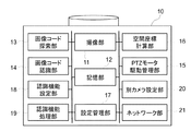
図3に示すように、カメラ10は、撮像部11と、記憶部12と、画像コード探索部13と、画像コード認識部14と、PTZモータ駆動管理部15と、空間座標計算部16と、設定管理部17と、を備える。さらに、カメラ10は、認識機能設定部18と、認識機能処理部19と、別カメラ設定部20と、ネットワーク部21と、を備える。
撮像部11は、被写体の撮像を行うためのものであり、CMOS(Complementary Metal Oxide Semiconductor)、CCD(Charge Coupled Device)等の撮像素子を含んで構成される。記憶部12は、撮像部11が撮像した画像フレーム、及び当該画像フレームを圧縮して構成した動画データを記憶する。画像コード探索部13は、記憶部12に記憶された画像フレームを読み出し、画像フレームから規定の画像コードを探索する。画像コード認識部14は、画像コード探索部13によって探索された画像コードに埋め込まれた設定情報を認識する。
Hereinafter, the configuration of the
As shown in FIG. 3, the
The
PTZモータ駆動管理部15は、カメラ10の方向(パン位置、チルト位置)と画角(ズーム位置)とを設定する。PTZモータ駆動管理部15は、パン位置、チルト位置、ズーム位置をそれぞれ表す数値に基づいて、パン、チルト、ズームの駆動用モータを制御する。なお、パン位置、チルト位置、ズーム位置の数値を、PTZモータ駆動管理部15から読み出すことも可能である。空間座標計算部16は、PTZモータ駆動管理部15からパン位置、チルト位置、ズーム位置の数値を読み出し、カメラ10の姿勢(方向、画角)を取得する。また、空間座標計算部16は、取得したカメラ10の姿勢と、画像フレーム中における画像コードの位置とに基づいて、画像コードの空間位置(ワールド座標)を計算する。
The PTZ motor
設定管理部17は、設定情報の管理と設定モードの管理とを行う。設定管理部17は、ユーザの指示によりカメラ10が設定モードで起動された場合に、カメラ設定処理を実行可能な状態とする。また、このとき設定管理部17は、画像コード認識部14が画像コードから認識した設定情報と、空間座標計算部16が計算した画像コードの空間位置情報とを取得する。設定管理部17は、これらの情報をもとに、画像解析処理で用いるパラメータの設定を行う。
例えば、何歳位の人が商品を手に取ったかを検出する場合、商品が陳列された棚等を含む所定の領域内に人が侵入したことを検出するための侵入検出機能や、商品を見る人の顔の角度や大きさ、年齢を検出するための顔検出機能を起動する必要がある。設定情報の中に、侵入検出領域を設定するためのパラメータ設定情報が含まれている場合、設定管理部17は、当該パラメータ設定情報に基づいて、上記パラメータとして侵入検出領域を決定する。
The
For example, when detecting the age of a person who picked up a product, an intrusion detection function for detecting that a person has entered a predetermined area including a shelf or the like on which the product is displayed, or a It is necessary to activate a face detection function for detecting the angle, size, and age of the viewer's face. If the setting information includes parameter setting information for setting an intrusion detection area, the
また、例えば、店舗内の人数をカウントする場合、人物が所定の線を通過したことを検出するための通過検出機能を起動する必要がある。設定情報の中に、通過検出線を設定するためのパラメータ設定情報が含まれている場合、設定管理部17は、当該パラメータ設定情報に基づいて、上記パラメータとして通過検出線を決定する。
さらに、設定情報の中に、カメラ10による監視対象範囲を設定するためのパラメータ設定情報が含まれている場合、設定管理部17は、当該パラメータ設定情報に基づいて、上記パラメータとして監視対象範囲および撮像条件を決定する。ここで、撮像条件とは、上記監視対象範囲を撮像するためのカメラ10の姿勢等である。
このように、パラメータ設定情報は、侵入検出領域や通過検出線、撮像範囲等、実空間上の位置に関するパラメータを設定するための情報である。
For example, when counting the number of people in a store, it is necessary to activate a passage detection function for detecting that a person has passed a predetermined line. If the setting information includes parameter setting information for setting the passage detection line, the
Further, when the setting information includes parameter setting information for setting the monitoring target range by the
As described above, the parameter setting information is information for setting parameters related to positions in the real space, such as an intrusion detection area, a passage detection line, and an imaging range.
認識機能設定部18は、画像コード認識部14が画像コードから認識した設定情報の中に含まれる機能設定情報をもとに、起動すべき画像解析機能(認識機能)を選択し、当該画像解析機能を起動するための設定を行う。認識機能処理部19は、認識機能設定部18が設定した画像解析機能(認識機能)を実現するための画像解析処理を実行する。
別カメラ設定部20は、他のカメラに対して、ネットワーク部21を介して設定コマンド等を送信する。ネットワーク部21は、ネットワークを介して他のカメラや、管理端末50もしくはVMS(Video Management Software)端末との間で、設定コマンドや画像データのやり取りを仲介する。
図3に示す各要素は、それぞれ別個のハードウェアとしてカメラ10を構成させることができる。この場合、図4に示すCPU101の制御に基づいて、図3の各要素が別個のハードウェアとして動作する。ただし、各要素の一部または全部の機能が図4に示すCPU101によって実行されてもよい。
The recognition
The different
Each element shown in FIG. 3 can configure the
図4に示すように、カメラ10は、CPU101と、ROM102と、RAM103と、外部メモリ104と、撮像部105と、入力部106と、ネットワーク部(通信I/F)107と、システムバス108とを備える。CPU101は、カメラ10における動作を統括的に制御するものであり、システムバス108を介して、各構成部(102〜107)を制御する。ROM102は、CPU101が処理を実行するために必要な制御プログラム等を記憶する不揮発性メモリである。なお、当該プログラムは、外部メモリ104や着脱可能な記憶媒体(不図示)に記憶されていてもよい。RAM103は、CPU101の主メモリ、ワークエリア等として機能する。すなわち、CPU101は、処理の実行に際してROM102から必要なプログラム等をRAM103にロードし、当該プログラム等を実行することで各種の機能動作を実現する。
As shown in FIG. 4, the
外部メモリ104は、例えば、CPU101がプログラムを用いた処理を行う際に必要な各種データや各種情報等を記憶している。また、外部メモリ104には、例えば、CPU101がプログラム等を用いた処理を行うことにより得られた各種データや各種情報等が記憶される。撮像部105は、図3の撮像部11に対応する。入力部106は電源ボタンなどから構成され、カメラ10のユーザは、入力部106を介して当該カメラ10に指示を与えることができるようになっている。ネットワーク部107は、図3のネットワーク部21に対応する。図3に示すカメラ10の各要素の一部または全部の機能は、CPU101がROM102もしくは外部メモリ104に記憶されたプログラムを実行することで実現されてもよい。
なお、本実施形態では、カメラ10が画像処理装置として動作する例を説明するが、管理端末50が画像処理装置として動作してもよいし、一般のPCや他の機器が画像処理装置として動作してもよい。
The
In the present embodiment, an example in which the
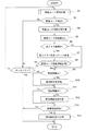
図5は、カメラ10の動作を説明するためのフローチャートである。なお、本実施形態では、図3で示す各要素がそれぞれ別個のハードウェアとして動作することで、図5の処理が実行される場合の例を中心に説明する。ただし、図3の各要素の一部又は全部の機能が、カメラ10のCPU101により実現されるようにしてもよい。本実施形態の他のフローチャートについても、同様である。この図5の処理は、例えば、カメラ10が設定モードで起動されたときに開始される。ただし、図5の処理の開始タイミングは、上記のタイミングに限らない。
FIG. 5 is a flowchart for explaining the operation of the
S1において、画像コード探索部13は、画像コード探索処理を行う。画像コード探索処理は、撮像部11によって所定の探索対象範囲を撮像し、その撮像画像から画像コードを探索する処理である。本実施形態では、カメラ10の撮像可能範囲を探索対象範囲とし、パン機構、チルト機構及びズーム機構を用いてカメラ10の姿勢を制御しながら、画像コードを探索する。このS1では、図6に示す処理を実行する。
先ずS101において、画像コード探索部13は、カメラ10のズームレンズをWide端(広角端)に移動する。次にS102において、画像コード探索部13は、撮像部11を制御して撮像した画像フレームを取得する。S103では、画像コード探索部13は、撮像部11によって撮像した画像フレーム内において画像コードの有無を探索する。
In S1, the image
First, in S101, the image
S104では、画像コード探索部13は、画像フレームから画像コードを検出できたか否かを判定する。画像コード探索部13は、画像コードを検出できなかったと判定した場合、S105に移行し、画像コードを検出できたと判定した場合、図5に戻る。
S105では、画像コード探索部13は、ズーム位置を固定した状態で、パン位置及びチルト位置を可動範囲内で1単位移動させる。本実施形態では、最小画像コードの大きさに応じて、上記の移動単位を決定する。S106では、画像コード探索部13は、パン位置及びチルト位置が、パン、チルトの可動範囲を移動し終わった位置であるか否かを判定する。そして、可動範囲を移動し終わっていない場合はS102に戻り、可動範囲を移動し終わっている場合はS107に移行する。
In S104, the image
In S105, the image
S107では、画像コード探索部13は、ズーム位置を1段階Tele端(望遠端)側に移動し、S108に移行する。S108では、画像コード探索部13は、ズーム位置がTele端に達しているか否かを判定する。そして、Tele端に達していない場合はS102に戻り、Tele端に達している場合は、図5に戻る。
図5のS2では、CPU101は、S1の画像コード探索処理において画像コードを検出できたか否かを判定する。そして、画像コードが非検出である場合にはS3に移行し、画像コードを検出できている場合にはS4に移行する。S3では、CPU101は、探索時間をタイムアウト判定する。このとき、タイムアウトしていない場合は、画像コード探索処理を再度行うとしてS1に戻る。一方、タイムアウトした場合は、そのまま処理を終了する。
In S107, the image
In S2 of FIG. 5, the
S4では、空間座標計算部16は、検出した画像コードの実空間上の位置を計算する。先ず、PTZモータ駆動管理部15は、当該画像コードが画像フレーム内の中心に位置するように、カメラ10の姿勢を制御する。次に、空間座標計算部16は、PTZモータ駆動管理部15より、カメラ10のパン位置、チルト位置、ズーム位置の各数値を読み出し、カメラ10の姿勢情報を取得する。そして、空間座標計算部16は、取得したカメラ10の姿勢情報をもとに、画像コードの位置を計算する。ここで、画像コードの位置としては、画像フレーム内位置(カメラ座標)と空間位置(ワールド座標)の両方を計算する。空間位置(ワールド位置)の導出に際しては、例えば光線交差法を用いることができる。
In S4, the space coordinate
S5では、画像コード認識部14は、検出した画像コードに埋め込まれた設定情報を読み出し、S6に移行する。
S6では、設定管理部17は、画像コード中の設定情報に含まれる機能設定情報を確認する。また、設定管理部17は、機能設定情報が、複数台のカメラによって監視対象範囲を監視する多カメラ監視機能を起動することを示す情報であるか否かを判定する。そして、多カメラ監視であると判定した場合にはS7に移行し、多カメラ監視ではないと判定した場合にはS9に移行する。
In S5, the image
In S6, the
S7では、別カメラ設定部20は、検出した画像コードを他のカメラに探索させるための探索コマンドを、ネットワーク部21を介してカメラに対して送信する。探索コマンドは、自カメラで検出した画像コードの空間位置を示す情報、及び当該画像コードに埋め込まれた設定情報を含む。探索コマンドを受信したカメラは、探索コマンドによって指定された空間位置に画像コードが存在するか否かを探索する。そして、画像コードを検出(認識)できた場合、探索コマンドを送信してきたカメラに対して画像コード認識情報を送信する。探索コマンドを受信したカメラが実行する処理については後述する。
S8では、設定管理部17は、ネットワーク部21を介して他のカメラが送信した画像コード認識情報を受信したか否かを判定する。そして、設定管理部17は、当該認識情報を受信したと判定した場合にはS9に移行し、認識情報を受信していないと判定した場合にはS3に移行する。
In S7, the different
In S8, the
S9では、設定管理部17は、画像コード中の設定情報に含まれるパラメータ設定情報を確認する。また、設定管理部17は、パラメータ設定情報が、実空間上に設定する仮想線分の端点に関する情報(端点情報)であるか否かを判定する。そして、設定管理部17は、パラメータ設定情報が端点情報であると判定した場合、S10に移行し、端点情報ではないと判定した場合、S11に移行する。S10では、設定管理部17は、上記端点情報に基づいて、画像解析処理で用いるパラメータとして、仮想線分(検出線)を決定する。このとき、設定管理部17は、画像コードの空間位置を仮想線分の端点位置として設定する。そして、設定管理部17は、2つの端点を結んだ線分を検出線として決定する。
In S9, the
S11では、設定管理部17は、パラメータ設定情報が、実空間上に設定する仮想閉領域の頂点に関する情報(頂点情報)であるか否かを判定する。そして、設定管理部17は、パラメータ設定情報が頂点情報であると判定した場合、S12に移行し、頂点情報ではないと判定した場合、S13に移行する。S12では、設定管理部17は、上記頂点情報に基づいて、画像解析処理で用いるパラメータとして、仮想閉領域(検出領域)を決定する。このとき、設定管理部17は、画像コードの空間位置を仮想閉領域の頂点位置として設定する。そして、設定管理部17は、複数の頂点を結んだ閉領域を検出領域として決定する。
In S11, the
S13では、設定管理部17は、画像コード中の設定情報に機能設定情報が含まれているか否かを判定する。そして、設定管理部17は、機能設定情報が含まれていると判定した場合、画像解析機能(認識機能)を設定すると判断し、認識機能設定部18に対して認識機能設定を依頼してからS14に移行する。一方、設定管理部17は、機能設定情報が含まれていないと判定した場合、そのまま処理を終了する。
In S13, the
S14では、認識機能設定部18は、設定依頼を受けた画像解析機能(認識機能)の設定を実施する。認識機能設定部18は、例えば通過検出機能の設定を依頼されている場合、S10において決定した検出線を通過検出線とした通過検出機能の設定を行う。また、認識機能設定部18は、例えば侵入検出機能の設定を依頼されている場合、S12において決定した検出領域を侵入検出領域とした侵入検出機能の設定を行う。さらに、認識機能設定部18は、例えば状況解析機能の設定を依頼されている場合、S12において決定した検出領域を監視対象範囲(カメラ10の撮像範囲)として設定する。認識機能設定部18は、S4において計算した画像コードの空間位置を含む領域を監視対象範囲として設定することもできる。そして、認識機能設定部18は、設定した監視対象範囲を撮像できるようにカメラ10のアングルを調整し、画像解析処理を実行可能な状態とする。また、認識機能設定部18は、認識機能処理部19に画像解析処理の開始を指示する。
In S14, the recognition
次に、上記の探索コマンドを受信した際のカメラの動作について説明する。以下、カメラ10が他のカメラから探索コマンドを受信したときの動作について、図7を参照しながら説明する。本実施形態では、図3で示す各要素がそれぞれ別個のハードウェアとして動作することで、図7の処理が実行される場合の例を中心に説明する。ただし、図3の各要素の一部又は全部の機能が、カメラ10のCPU101により実現されるようにしてもよい。
先ずS21において、CPU101は、ネットワーク部21を介して探索コマンドを受信したか否かを判定する。そして、探索コマンドを受信していない場合には当該探索コマンドを受信するまで待機し、探索コマンドを受信したらS22に移行する。S22では、画像コード探索部13は、上述した図6に示す画像コード探索処理を行う。
Next, the operation of the camera when receiving the above search command will be described. Hereinafter, an operation when the
First, in S21, the
次にS23では、CPU101は、S21の画像コード探索処理において、探索コマンドとして受信した空間位置(ワールド座標点)に画像コードを検出できたか否かを判定する。そして、画像コードが非検出である場合にはS24に移行し、画像コードを検出できている場合にはS25に移行する。S24では、CPU101は、探索時間をタイムアウト判定する。このとき、タイムアウトしていない場合は、画像コード探索処理を再度行うとしてS22に戻る。一方、タイムアウトした場合は、そのまま処理を終了する。
Next, in S23, the
S25では、別カメラ設定部20は、探索コマンドを送信してきたカメラに対して、画像コードを検出(認識)できたことを示す画像コード認識情報を、ネットワーク部21を介して送信する。S26〜S31においては、上述した図5のS9〜S14と同様の処理を実施する。すなわち、設定管理部17は、探索コマンドとして受信した画像コード中の設定情報に基づいて、画像解析処理に関する設定を行う。
これにより、監視対象範囲を、異なる角度や画角あるいはズーム倍率によって複数のカメラ10が監視することができる。したがって、例えば侵入検出機能を有効とした場合、所定の検出領域に侵入した人物の検出漏れを抑制し、当該人物の追尾精度等の向上が期待できる。
In S25, the separate
Thereby, the plurality of
図8において、画像コード201及び202は、パラメータ設定情報として、共通の検出線の端点であることを示す端点情報が埋め込まれたカラーコードである。画像コード203及び204も同様である。これらの画像コード201〜204を、図8に示すように撮像現場である店舗内に配置し、カメラ10Aを設定モードで起動すると、カメラ10Aはカメラ設定処理を開始する。
先ず、カメラ10Aは、画像コード探索処理により、画像コード201〜204を検出する。そして、カメラ10Aは、画像コード201〜204の空間位置を計算し、画像コード201〜204に埋め込まれた設定情報を読み出す。各画像コードには端点情報が埋め込まれているため、カメラ10Aは、当該端点情報をもとに検出線を決定する。このとき、カメラ10Aは、検出線として、画像コード201の空間位置と画像コード202の空間位置とをそれぞれ端点位置とした検出線211を決定する。また、カメラ10Aは、画像コード203の空間位置と画像コード204の空間位置とをそれぞれ端点位置とした検出線212を決定する。そして、カメラ10Aは、検出線211及び212を通過検出線として用いた通過検出機能を起動する。
8,
First, the
また、図9において、画像コード205〜208は、パラメータ設定情報として、共通の検出領域の頂点であることを示す頂点情報が埋め込まれたカラーコードである。これらの画像コード205〜208を、図9に示すように撮像現場である店舗内に配置し、カメラ10Aを設定モードで起動すると、カメラ10Aはカメラ設定処理を開始する。
先ず、カメラ10Aは、画像コード探索処理により、画像コード205〜208を検出する。そして、カメラ10Aは、画像コード205〜208の空間位置を計算し、画像コード205〜208に埋め込まれた設定情報を読み出す。各画像コードには頂点情報が埋め込まれているため、カメラ10Aは、当該頂点情報をもとに検出領域を決定する。このとき、カメラ10Aは、検出領域として、画像コード205〜208の各空間位置を頂点位置とした検出領域221を決定する。そして、カメラ10Aは、検出領域221を侵入検出領域として用いた侵入検出機能を起動する。
In FIG. 9,
First, the
以上説明したとおり、本実施形態では、カメラ10は、撮像画像から画像コードを検出し、当該画像コードに含まれる設定情報を取得する。そして、カメラ10は、取得した設定情報に基づいて、画像解析処理に関する設定を行う。
ここで、画像解析処理に関する設定とは、画像解析処理の実行に必要なパラメータの設定である。画像コードに埋め込まれた上記パラメータを設定するためのパラメータ設定情報に基づいて当該パラメータを設定するので、画像解析処理に関する設定を容易に行うことができる。
As described above, in the present embodiment, the
Here, the setting relating to the image analysis processing is the setting of parameters necessary for executing the image analysis processing. Since the parameters are set based on the parameter setting information for setting the parameters embedded in the image code, the settings relating to the image analysis processing can be easily performed.
特に、監視対象領域や動体の通過検出のための検出線、動体の侵入検出のための検出領域等の実空間上の位置に関するパラメータを設定することができる。そのため、ユーザは、カメラ設置時に、設定画面に表示されたカメラ映像等を見ながら検出線や検出領域の枠を引く操作を行う必要がない。このように、設定画面を見て操作することなく画像解析処理に関する設定が可能となる。
また、パラメータ設定情報として、実空間上に設定する仮想線分の端点や仮想閉領域の頂点に関する情報を画像コードに埋め込むことで、上記パラメータを容易に設定することができる。
In particular, it is possible to set parameters relating to positions in the real space, such as a monitoring target area, a detection line for detecting the passage of a moving object, and a detection area for detecting intrusion of a moving object. Therefore, at the time of installing the camera, the user does not need to perform an operation of drawing a frame of the detection line or the detection area while viewing the camera image or the like displayed on the setting screen. In this way, it is possible to make settings relating to the image analysis processing without looking at the setting screen and performing operations.
Further, the parameter can be easily set by embedding information regarding the end point of the virtual line segment set in the real space and the vertex of the virtual closed area into the image code as the parameter setting information.
例えば、パラメータ設定情報は、画像コードの設置位置が仮想線分の端点位置や仮想閉領域の頂点位置であることを示す情報とすることができる。この場合、画像コードの撮像画像内における位置と、当該撮像画像を撮像したカメラ10の撮像条件とに基づいて、画像コードの実空間上の位置を導出することで、検出線や検出領域等のパラメータを設定することができる。すなわち、画像コードを、画像解析処理に関する設定に用いる実空間位置に対応した位置に直接配置することで、位置に関するパラメータを容易且つ適切に設定することができる。
For example, the parameter setting information may be information indicating that the installation position of the image code is an end position of a virtual line segment or a vertex position of a virtual closed area. In this case, by deriving the position of the image code in the real space based on the position of the image code in the captured image and the imaging conditions of the
このように、画像コードを実空間上に配置することで、管理端末等の設定画面上で行わなければならなかった設定操作を、設定画面を操作することなく容易に行うことができる。例えば、実空間上の仮想線分の端点位置にそれぞれ画像コードを配置する。そして、各画像コードの撮像画像と撮像条件とに基づいて、各画像コードの実空間位置を導出する。これにより、2つの端点を結ぶ仮想線分を容易に決定することができる。したがって、決定した仮想線分を動体の通過検出のための検出線として設定すれば、通過検出機能の実現が可能となる。 Thus, by arranging the image codes in the real space, the setting operation that had to be performed on the setting screen of the management terminal or the like can be easily performed without operating the setting screen. For example, the image code is arranged at each end position of the virtual line segment in the real space. Then, a real space position of each image code is derived based on a captured image of each image code and an imaging condition. This makes it possible to easily determine a virtual line segment connecting the two end points. Therefore, if the determined virtual line segment is set as a detection line for detecting passage of a moving object, a passage detection function can be realized.
また、同様に、実空間上の例えば矩形状の仮想閉領域の頂点位置にそれぞれ画像コードを配置すれば、4つの頂点を結ぶ仮想閉領域を容易に決定することができる。したがって、決定した仮想閉領域を動体の侵入検出のための検出領域として設定すれば、侵入検出機能の実現が可能となる。さらに、決定した仮想閉領域をカメラ10による監視対象領域として設定すれば、各種状況解析機能の実現が可能となる。また、実空間上の監視対象位置に画像コードを配置し、当該監視対象位置が含まれる所定領域をカメラ10の監視対象領域として設定することもできる。
Similarly, if image codes are respectively arranged at the vertices of a virtual closed area in a real space, for example, a virtual closed area connecting four vertices can be easily determined. Therefore, if the determined virtual closed area is set as a detection area for detecting intrusion of a moving object, an intrusion detection function can be realized. Furthermore, if the determined virtual closed area is set as a monitoring target area by the
また、画像解析処理に関する設定として、カメラ10の監視対象範囲を設定した場合、カメラ10が当該監視対象範囲を撮像するように撮像条件(撮像方向や画角等)を制御することができる。このように、設定画面上でカメラ映像を確認しながら監視対象範囲を設定しなくてよいため、煩雑な設定操作が不要となる。
さらに、画像解析処理に関する設定として、複数の画像解析機能のうち、有効にする画像解析機能を指定する機能設定情報を用いることもできる。これにより、実行する画像解析処理の選択を容易に行うことができる。したがって、所望の画像解析機能を適切に実現することができる。
以上のように、本実施形態では、カメラ10の設置時にユーザが管理画面を見て操作することなく、カメラ機能やカメラアングル等を設定することが可能となるため、カメラ設置時の利便性を向上させることができる。
In addition, when a monitoring target range of the
Further, as the setting relating to the image analysis processing, function setting information for designating an image analysis function to be enabled among a plurality of image analysis functions can be used. This makes it easy to select an image analysis process to be executed. Therefore, a desired image analysis function can be appropriately realized.
As described above, in the present embodiment, since the user can set the camera function, the camera angle, and the like without installing the
(変形例)
なお、上記実施形態においては、画像コードが存在する空間位置(ワールド座標点)の計算に、画像データの仮想床面を設定した光線交差法を用いているが、これに限定するものではない。例えば、赤外線深度センサと赤外光とを用いて赤外光画像を撮像し、当該赤外光画像と可視光画像とにより空間位置を計算してもよい。また、カメラ10とは別体のTOF(Time Of Flight)方式の距離画像カメラを用いて空間位置を計算してもよい。
また、上記実施形態においては、人物の顔検出、顔認証、人体の軌跡情報の取得機能設定を画像コードに埋め込んでもよい。
(Modification)
In the above embodiment, the ray intersection method in which the virtual floor of the image data is set is used for calculating the spatial position (world coordinate point) where the image code exists, but the present invention is not limited to this. For example, an infrared light image may be captured using an infrared depth sensor and infrared light, and the spatial position may be calculated based on the infrared light image and the visible light image. Alternatively, the spatial position may be calculated by using a distance image camera of a TOF (Time Of Flight) system separate from the
Further, in the above-described embodiment, the setting of the function of detecting the face of a person, authenticating the face, and acquiring the trajectory information of the human body may be embedded in the image code.
さらに、上記実施形態においては、侵入検出機能で用いる検出領域を、図9に示すように矩形としているが、これに限定するものではない。例えば、楕円や円形等の任意の閉領域を画像コードで指定してもよい。また、画像コードの空間位置を検出線の端点位置や検出領域の頂点位置とする場合について説明したが、画像コードに検出線の端点の空間位置情報や検出領域の頂点の空間位置情報を直接埋め込んでもよい。この場合、画像コードに埋め込まれた設定情報のみに基づいて検出線や検出領域等のパラメータを設定することができ、画像コードの空間位置を導出する処理が不要となる。
また、上記実施形態においては、他の画像解析機能として、置き去りや持ち去りの対象物を特定するために画像コードを用いてもよい。
さらに、上記実施形態においては、画像コードに埋め込む設定情報として、カメラ10の姿勢(方向、画角)を自動で移動させる自動巡回機能(オートパイロット)に関する設定情報を用いることもできる。
Furthermore, in the above embodiment, the detection area used in the intrusion detection function is rectangular as shown in FIG. 9, but is not limited to this. For example, an arbitrary closed area such as an ellipse or a circle may be designated by an image code. Also, the case has been described where the spatial position of the image code is used as the end point position of the detection line or the vertex position of the detection region. However, the spatial position information of the end point of the detection line or the spatial position information of the vertex of the detection region is directly embedded in the image code. May be. In this case, parameters such as a detection line and a detection area can be set based only on the setting information embedded in the image code, and the process of deriving the spatial position of the image code becomes unnecessary.
Further, in the above-described embodiment, as another image analysis function, an image code may be used to specify an object to be left or carried away.
Further, in the above embodiment, as the setting information to be embedded in the image code, setting information regarding an automatic cruising function (autopilot) for automatically moving the attitude (direction, angle of view) of the
また、上記実施形態においては、カメラ10としてPTZカメラを用いる場合について説明したが、これに限定されるものではなく、以下の変形が可能である。例えば、ズームのみできる機構を有するカメラや、固定点監視のカメラを用い、画像フレーム内の画像コード検出を行うように構成してもよい。
さらに、上記実施形態においては、複数のカメラ10によって、複数の監視対象箇所をカバーできるように各カメラアングルを調整することもできる。例えば、画像コードを複数の監視対象箇所にそれぞれ設置し、複数のカメラ10によって一斉に画像コードの探索処理を行う。そして、複数のカメラ10で相互に通信して認識した画像コードの情報を交換し、実空間に設置した画像コードをそれぞれ複数のカメラ10の少なくとも1台で撮像できるように、各カメラ10の向きと撮像範囲とを自動で設定する。これにより、複数カメラの設定を容易に行うことができる。
In the above embodiment, the case where the PTZ camera is used as the
Further, in the above embodiment, each camera angle can be adjusted so that a plurality of monitoring targets can be covered by the plurality of
(その他の実施形態)
本発明は、上述の実施形態の1以上の機能を実現するプログラムを、ネットワーク又は記憶媒体(または記録媒体)を介してシステム又は装置に供給し、そのシステム又は装置のコンピュータにおける1つ以上のプロセッサーがプログラムを読出し実行する処理でも実現可能である。また、1以上の機能を実現する回路(例えば、ASIC)によっても実現可能である。
(Other embodiments)
The present invention supplies a program for realizing one or more functions of the above-described embodiments to a system or an apparatus via a network or a storage medium (or a recording medium), and executes one or more processors in a computer of the system or the apparatus. Can read out and execute a program. Further, it can be realized by a circuit (for example, an ASIC) that realizes one or more functions.
10…カメラ、11…撮像部、12…記憶部、13…画像コード探索部、14…画像コード認識部、15…PTZモータ駆動管理部、16…空間座標計算部、17…設定管理部、18…認識機能設定部、19…認識機能処理部、20…別カメラ設定部、21…ネットワーク部、30…ハブ、50…管理端末、100…ネットワークカメラシステム、200〜208…画像コード、211,212…検出線、221…検出領域
DESCRIPTION OF
Claims (11)
前記取得手段で取得した前記情報に基づいて前記画像解析機能を実行するための設定を行う設定手段と、を備え、
前記情報は、前記画像解析機能の実行に必要なパラメータとして、実空間上の位置に関する設定を行うためのパラメータを有し、
前記設定手段は、前記パラメータに基づいて、前記画像解析機能に関する設定を行うことを特徴とする画像処理装置。 Acquisition means for recognizing a predetermined feature having information specifying an image analysis function from a captured image of the surveillance camera, and acquiring the information,
Setting means for performing settings for executing the image analysis function based on the information acquired by the acquiring means ,
The information, as a parameter necessary for the execution of the image analysis function, has a parameter for performing settings related to the position in the real space,
The image processing apparatus according to claim 1, wherein the setting unit performs setting related to the image analysis function based on the parameter .
前記設定手段は、前記情報と、前記導出手段で導出した前記所定の特徴の実空間上の位置とに基づいて、前記画像解析機能を実行するための設定を行うことを特徴とする請求項1乃至3のいずれか1項に記載の画像処理装置。 Deposition means for deriving a position of the predetermined feature in a real space based on position information of the predetermined feature in the captured image and an imaging condition of the monitoring camera which has captured the captured image,
The setting means, and the information, based on the position in the real space of the predetermined feature derived by the deriving means, claim 1, characterized in that the setting for executing the image analysis function The image processing device according to any one of claims 1 to 3 .
前記設定手段は、前記導出手段で導出した複数の所定の特徴の実空間上の位置を仮想線分の端点の位置とし、当該端点を結んだ仮想線分を、前記パラメータである動体の通過検出のための検出線として設定することを特徴とする請求項4に記載の画像処理装置。 The deriving unit derives the positions of the plurality of predetermined features in the real space,
The setting unit sets a position in the real space of the plurality of predetermined features derived by the deriving unit as a position of an end point of a virtual line segment, and determines a virtual line segment connecting the end points as a moving object passing detection which is the parameter. The image processing apparatus according to claim 4 , wherein the detection line is set as a detection line.
前記設定手段は、前記導出手段で導出した複数の所定の特徴の実空間上の位置を仮想閉領域の頂点の位置とし、当該頂点を結んだ仮想閉領域を、前記パラメータである動体の侵入検出のための検出領域として設定することを特徴とする請求項4に記載の画像処理装置。 The deriving unit derives the positions of the plurality of predetermined features in the real space,
The setting unit sets a position in the real space of the plurality of predetermined features derived by the deriving unit as a position of a vertex of the virtual closed region, and determines a virtual closed region connecting the vertices as a moving object intrusion detection which is the parameter. The image processing apparatus according to claim 4 , wherein the image processing apparatus is set as a detection area.
取得した前記情報に基づいて、前記画像解析機能を実行するための設定を行う設定ステップと、を有し、
前記情報は、前記画像解析機能の実行に必要なパラメータとして、実空間上の位置に関する設定を行うためのパラメータを有し、
前記設定ステップでは、前記パラメータに基づいて、前記画像解析機能に関する設定を行うことを特徴とする画像処理方法。 From a captured image of the surveillance camera, recognizing a predetermined feature having information specifying an image analysis function, an obtaining step of obtaining the information,
Based on the acquired information, have a, a setting step of performing setting for executing the image analysis function,
The information, as a parameter necessary for the execution of the image analysis function, has a parameter for performing settings related to the position in the real space,
The image processing method , wherein in the setting step, setting relating to the image analysis function is performed based on the parameter .
Priority Applications (3)
| Application Number | Priority Date | Filing Date | Title |
|---|---|---|---|
| JP2015076526A JP6624800B2 (en) | 2015-04-03 | 2015-04-03 | Image processing apparatus, image processing method, and image processing system |
| US15/086,848 US9773143B2 (en) | 2015-04-03 | 2016-03-31 | Image processing apparatus, image processing method, and image processing system |
| US15/691,445 US10127424B2 (en) | 2015-04-03 | 2017-08-30 | Image processing apparatus, image processing method, and image processing system |
Applications Claiming Priority (1)
| Application Number | Priority Date | Filing Date | Title |
|---|---|---|---|
| JP2015076526A JP6624800B2 (en) | 2015-04-03 | 2015-04-03 | Image processing apparatus, image processing method, and image processing system |
Publications (3)
| Publication Number | Publication Date |
|---|---|
| JP2016197797A JP2016197797A (en) | 2016-11-24 |
| JP2016197797A5 JP2016197797A5 (en) | 2018-05-10 |
| JP6624800B2 true JP6624800B2 (en) | 2019-12-25 |
Family
ID=57015218
Family Applications (1)
| Application Number | Title | Priority Date | Filing Date |
|---|---|---|---|
| JP2015076526A Active JP6624800B2 (en) | 2015-04-03 | 2015-04-03 | Image processing apparatus, image processing method, and image processing system |
Country Status (2)
| Country | Link |
|---|---|
| US (2) | US9773143B2 (en) |
| JP (1) | JP6624800B2 (en) |
Families Citing this family (5)
| Publication number | Priority date | Publication date | Assignee | Title |
|---|---|---|---|---|
| JP6909083B2 (en) * | 2017-07-18 | 2021-07-28 | キヤノン株式会社 | Information processing equipment, information processing methods, and programs |
| JP6907079B2 (en) * | 2017-09-14 | 2021-07-21 | キヤノン株式会社 | Imaging device, control method and program of imaging device |
| JP2019086310A (en) * | 2017-11-02 | 2019-06-06 | 株式会社日立製作所 | Distance image camera, distance image camera system and control method thereof |
| JP7071861B2 (en) * | 2018-03-30 | 2022-05-19 | セコム株式会社 | Marker detection system |
| US11558539B2 (en) * | 2019-03-13 | 2023-01-17 | Smart Supervision System LLC | Systems and methods of detecting and identifying an object |
Family Cites Families (8)
| Publication number | Priority date | Publication date | Assignee | Title |
|---|---|---|---|---|
| JP4416550B2 (en) | 2004-03-29 | 2010-02-17 | 富士フイルム株式会社 | Digital still camera and control method thereof |
| JP2007282100A (en) * | 2006-04-11 | 2007-10-25 | Canon Inc | Image processing system and image processing method |
| JPWO2008149709A1 (en) * | 2007-06-04 | 2010-08-26 | シャープ株式会社 | Portable terminal, portable terminal control method, portable terminal control program, and computer-readable recording medium recording the same |
| JP4663767B2 (en) * | 2008-09-01 | 2011-04-06 | 株式会社日立製作所 | Image surveillance system |
| JPWO2011046127A1 (en) * | 2009-10-14 | 2013-03-07 | 日本電気株式会社 | Data collection system, portable terminal, seal, and data collection method |
| JP2011097284A (en) * | 2009-10-28 | 2011-05-12 | Panasonic Corp | Monitoring device |
| JP6226538B2 (en) * | 2013-03-15 | 2017-11-08 | キヤノン株式会社 | Display control apparatus, display control method, and program |
| JP2014236264A (en) * | 2013-05-31 | 2014-12-15 | ソニー株式会社 | Image processing apparatus, image processing method and program |
-
2015
- 2015-04-03 JP JP2015076526A patent/JP6624800B2/en active Active
-
2016
- 2016-03-31 US US15/086,848 patent/US9773143B2/en not_active Expired - Fee Related
-
2017
- 2017-08-30 US US15/691,445 patent/US10127424B2/en active Active
Also Published As
| Publication number | Publication date |
|---|---|
| US20170364724A1 (en) | 2017-12-21 |
| JP2016197797A (en) | 2016-11-24 |
| US9773143B2 (en) | 2017-09-26 |
| US10127424B2 (en) | 2018-11-13 |
| US20160292484A1 (en) | 2016-10-06 |
Similar Documents
| Publication | Publication Date | Title |
|---|---|---|
| US9805265B2 (en) | Surveillance camera control device and video surveillance system | |
| JP6532217B2 (en) | IMAGE PROCESSING APPARATUS, IMAGE PROCESSING METHOD, AND IMAGE PROCESSING SYSTEM | |
| JP4478510B2 (en) | Camera system, camera, and camera control method | |
| JP6624800B2 (en) | Image processing apparatus, image processing method, and image processing system | |
| US8410441B2 (en) | Thermal imaging camera for taking thermographic images | |
| US20080075334A1 (en) | Combined face and iris recognition system | |
| JP2010086336A (en) | Image control apparatus, image control program, and image control method | |
| CN105100596B (en) | Camera apparatus and the method for using camera apparatus tracking object | |
| KR20170041636A (en) | Display control apparatus, display control method, and program | |
| JP2019129410A (en) | Monitoring camera, control method thereof, and program | |
| JP2019054369A (en) | Imaging device, control method of imaging device, and program | |
| EP2648406B1 (en) | Method for switching viewing modes in a camera | |
| KR101452342B1 (en) | Surveillance Camera Unit And Method of Operating The Same | |
| JP2011109630A (en) | Universal head for camera apparatus | |
| KR101410985B1 (en) | monitoring system and monitoring apparatus using security camera and monitoring method thereof | |
| JP2013065971A (en) | Imaging device and control method for imaging device | |
| CN112514366A (en) | Image processing method, image processing apparatus, and image processing system | |
| JP2020088840A (en) | Monitoring device, monitoring system, monitoring method, and monitoring program | |
| KR101738514B1 (en) | Monitoring system employing fish-eye thermal imaging camera and monitoring method using the same | |
| JPH10188145A (en) | Automatic zoom monitoring device | |
| WO2020111053A1 (en) | Monitoring device, monitoring system, monitoring method, and monitoring program | |
| JP2018051669A (en) | Robot system and program | |
| KR101332820B1 (en) | System and Method for Tracking Object, Apparatus for Object Management and Driving Method Thereof, Image Device and Driving Method Thereof | |
| JP2020198468A (en) | Imaging apparatus, imaging method, and program | |
| JP7374692B2 (en) | Imaging device, imaging device control method, and program |
Legal Events
| Date | Code | Title | Description |
|---|---|---|---|
| A521 | Request for written amendment filed |
Free format text: JAPANESE INTERMEDIATE CODE: A523 Effective date: 20180326 |
|
| A621 | Written request for application examination |
Free format text: JAPANESE INTERMEDIATE CODE: A621 Effective date: 20180326 |
|
| A977 | Report on retrieval |
Free format text: JAPANESE INTERMEDIATE CODE: A971007 Effective date: 20181207 |
|
| A131 | Notification of reasons for refusal |
Free format text: JAPANESE INTERMEDIATE CODE: A131 Effective date: 20190108 |
|
| A521 | Request for written amendment filed |
Free format text: JAPANESE INTERMEDIATE CODE: A523 Effective date: 20190308 |
|
| A131 | Notification of reasons for refusal |
Free format text: JAPANESE INTERMEDIATE CODE: A131 Effective date: 20190709 |
|
| A521 | Request for written amendment filed |
Free format text: JAPANESE INTERMEDIATE CODE: A523 Effective date: 20190905 |
|
| TRDD | Decision of grant or rejection written | ||
| A01 | Written decision to grant a patent or to grant a registration (utility model) |
Free format text: JAPANESE INTERMEDIATE CODE: A01 Effective date: 20191029 |
|
| A61 | First payment of annual fees (during grant procedure) |
Free format text: JAPANESE INTERMEDIATE CODE: A61 Effective date: 20191126 |
|
| R151 | Written notification of patent or utility model registration |
Ref document number: 6624800 Country of ref document: JP Free format text: JAPANESE INTERMEDIATE CODE: R151 |