JP5766150B2 - Endoscope operation system - Google Patents
Endoscope operation system Download PDFInfo
- Publication number
- JP5766150B2 JP5766150B2 JP2012122489A JP2012122489A JP5766150B2 JP 5766150 B2 JP5766150 B2 JP 5766150B2 JP 2012122489 A JP2012122489 A JP 2012122489A JP 2012122489 A JP2012122489 A JP 2012122489A JP 5766150 B2 JP5766150 B2 JP 5766150B2
- Authority
- JP
- Japan
- Prior art keywords
- endoscope
- unit
- rotation
- angular velocity
- operation system
- Prior art date
- Legal status (The legal status is an assumption and is not a legal conclusion. Google has not performed a legal analysis and makes no representation as to the accuracy of the status listed.)
- Expired - Fee Related
Links
Images


Classifications
-
- A—HUMAN NECESSITIES
- A61—MEDICAL OR VETERINARY SCIENCE; HYGIENE
- A61B—DIAGNOSIS; SURGERY; IDENTIFICATION
- A61B1/00—Instruments for performing medical examinations of the interior of cavities or tubes of the body by visual or photographical inspection, e.g. endoscopes; Illuminating arrangements therefor
- A61B1/00002—Operational features of endoscopes
- A61B1/00004—Operational features of endoscopes characterised by electronic signal processing
- A61B1/00006—Operational features of endoscopes characterised by electronic signal processing of control signals
-
- A—HUMAN NECESSITIES
- A61—MEDICAL OR VETERINARY SCIENCE; HYGIENE
- A61B—DIAGNOSIS; SURGERY; IDENTIFICATION
- A61B1/00—Instruments for performing medical examinations of the interior of cavities or tubes of the body by visual or photographical inspection, e.g. endoscopes; Illuminating arrangements therefor
- A61B1/00002—Operational features of endoscopes
- A61B1/00043—Operational features of endoscopes provided with output arrangements
- A61B1/00045—Display arrangement
- A61B1/00048—Constructional features of the display
-
- A—HUMAN NECESSITIES
- A61—MEDICAL OR VETERINARY SCIENCE; HYGIENE
- A61B—DIAGNOSIS; SURGERY; IDENTIFICATION
- A61B1/00—Instruments for performing medical examinations of the interior of cavities or tubes of the body by visual or photographical inspection, e.g. endoscopes; Illuminating arrangements therefor
- A61B1/00147—Holding or positioning arrangements
- A61B1/00149—Holding or positioning arrangements using articulated arms
-
- A—HUMAN NECESSITIES
- A61—MEDICAL OR VETERINARY SCIENCE; HYGIENE
- A61B—DIAGNOSIS; SURGERY; IDENTIFICATION
- A61B1/00—Instruments for performing medical examinations of the interior of cavities or tubes of the body by visual or photographical inspection, e.g. endoscopes; Illuminating arrangements therefor
- A61B1/00147—Holding or positioning arrangements
- A61B1/0016—Holding or positioning arrangements using motor drive units
-
- A—HUMAN NECESSITIES
- A61—MEDICAL OR VETERINARY SCIENCE; HYGIENE
- A61B—DIAGNOSIS; SURGERY; IDENTIFICATION
- A61B1/00—Instruments for performing medical examinations of the interior of cavities or tubes of the body by visual or photographical inspection, e.g. endoscopes; Illuminating arrangements therefor
- A61B1/04—Instruments for performing medical examinations of the interior of cavities or tubes of the body by visual or photographical inspection, e.g. endoscopes; Illuminating arrangements therefor combined with photographic or television appliances
- A61B1/045—Control thereof
-
- A—HUMAN NECESSITIES
- A61—MEDICAL OR VETERINARY SCIENCE; HYGIENE
- A61B—DIAGNOSIS; SURGERY; IDENTIFICATION
- A61B1/00—Instruments for performing medical examinations of the interior of cavities or tubes of the body by visual or photographical inspection, e.g. endoscopes; Illuminating arrangements therefor
- A61B1/04—Instruments for performing medical examinations of the interior of cavities or tubes of the body by visual or photographical inspection, e.g. endoscopes; Illuminating arrangements therefor combined with photographic or television appliances
- A61B1/05—Instruments for performing medical examinations of the interior of cavities or tubes of the body by visual or photographical inspection, e.g. endoscopes; Illuminating arrangements therefor combined with photographic or television appliances characterised by the image sensor, e.g. camera, being in the distal end portion
-
- A—HUMAN NECESSITIES
- A61—MEDICAL OR VETERINARY SCIENCE; HYGIENE
- A61B—DIAGNOSIS; SURGERY; IDENTIFICATION
- A61B17/00—Surgical instruments, devices or methods, e.g. tourniquets
- A61B2017/00017—Electrical control of surgical instruments
- A61B2017/00216—Electrical control of surgical instruments with eye tracking or head position tracking control
-
- A—HUMAN NECESSITIES
- A61—MEDICAL OR VETERINARY SCIENCE; HYGIENE
- A61B—DIAGNOSIS; SURGERY; IDENTIFICATION
- A61B17/00—Surgical instruments, devices or methods, e.g. tourniquets
- A61B2017/00973—Surgical instruments, devices or methods, e.g. tourniquets pedal-operated
-
- A—HUMAN NECESSITIES
- A61—MEDICAL OR VETERINARY SCIENCE; HYGIENE
- A61B—DIAGNOSIS; SURGERY; IDENTIFICATION
- A61B34/00—Computer-aided surgery; Manipulators or robots specially adapted for use in surgery
- A61B34/30—Surgical robots
- A61B2034/301—Surgical robots for introducing or steering flexible instruments inserted into the body, e.g. catheters or endoscopes
-
- A—HUMAN NECESSITIES
- A61—MEDICAL OR VETERINARY SCIENCE; HYGIENE
- A61B—DIAGNOSIS; SURGERY; IDENTIFICATION
- A61B90/00—Instruments, implements or accessories specially adapted for surgery or diagnosis and not covered by any of the groups A61B1/00 - A61B50/00, e.g. for luxation treatment or for protecting wound edges
- A61B90/50—Supports for surgical instruments, e.g. articulated arms
- A61B2090/502—Headgear, e.g. helmet, spectacles
-
- A—HUMAN NECESSITIES
- A61—MEDICAL OR VETERINARY SCIENCE; HYGIENE
- A61B—DIAGNOSIS; SURGERY; IDENTIFICATION
- A61B34/00—Computer-aided surgery; Manipulators or robots specially adapted for use in surgery
- A61B34/30—Surgical robots
-
- A—HUMAN NECESSITIES
- A61—MEDICAL OR VETERINARY SCIENCE; HYGIENE
- A61B—DIAGNOSIS; SURGERY; IDENTIFICATION
- A61B5/00—Measuring for diagnostic purposes; Identification of persons
- A61B5/06—Devices, other than using radiation, for detecting or locating foreign bodies ; determining position of probes within or on the body of the patient
- A61B5/065—Determining position of the probe employing exclusively positioning means located on or in the probe, e.g. using position sensors arranged on the probe
- A61B5/067—Determining position of the probe employing exclusively positioning means located on or in the probe, e.g. using position sensors arranged on the probe using accelerometers or gyroscopes
Landscapes
- Life Sciences & Earth Sciences (AREA)
- Health & Medical Sciences (AREA)
- Surgery (AREA)
- Engineering & Computer Science (AREA)
- Biophysics (AREA)
- Medical Informatics (AREA)
- Nuclear Medicine, Radiotherapy & Molecular Imaging (AREA)
- Optics & Photonics (AREA)
- Pathology (AREA)
- Radiology & Medical Imaging (AREA)
- Veterinary Medicine (AREA)
- Biomedical Technology (AREA)
- Heart & Thoracic Surgery (AREA)
- Physics & Mathematics (AREA)
- Molecular Biology (AREA)
- Animal Behavior & Ethology (AREA)
- General Health & Medical Sciences (AREA)
- Public Health (AREA)
- Signal Processing (AREA)
- Endoscopes (AREA)
- Instruments For Viewing The Inside Of Hollow Bodies (AREA)
- Closed-Circuit Television Systems (AREA)
Description
本発明は、内視鏡操作システムに関する。 The present invention relates to an endoscope operation system.
外科手術において、術後の回復が速く、手術の際の傷口が小さい等の利点から開腹手術に代えて内視鏡手術が広く行われている。このような内視鏡手術においては、遠隔操作が可能なマスタスレーブ型の内視鏡操作システムが提案されている。このような内視鏡操作システムは、例えば、特許文献1にも示されるように、内視鏡のズームレンズの拡大率が、ヘッドマウントディスプレイ(以下、HMDともいう)内に設けられ手術者の頭の移動を検出する姿勢センサからの検出出力に基づいて制御されるものとされる。また、手術者の頭の移動は、磁界を発生する磁気ソースに対する姿勢センサの変位として取り出される。これにより、例えば、手術者が患者に対し左を向けば、内視鏡の固体撮像素子を通じて得られた撮像データに基づく左の画像がHMD内の一対の液晶モニタに映され、手術者が患者に近づいた場合、ズームレンズにより拡大された視野が得られることとなる。従って、手術者は、内視鏡が挿入された体腔内を立体的に観察できることとなる。
In surgery, endoscopic surgery is widely performed instead of laparotomy because of the advantages such as fast recovery after surgery and small wounds at the time of surgery. In such endoscopic surgery, a master-slave type endoscope operation system capable of remote operation has been proposed. In such an endoscope operation system, for example, as disclosed in
また、従来の内視鏡把持装置においては、5節リンク機構と、腹壁を貫通するトロッカーを腹壁部で保持するボールジョイント部と、リンク機構を駆動させる駆動部および操作部とにより内視鏡把持装置が構成されているものが提案されている。斯かる構成においては、内視鏡の一種である腹腔鏡は、ズーム式で、画面の遠近を素早く切り替えることができ、また、コントローラスイッチにより、ズーム式の腹腔鏡が手術者の欲する位置に迅速に移動可能とされる。 Further, in a conventional endoscope gripping device, an endoscope is gripped by a five-node link mechanism, a ball joint portion that holds a trocar penetrating the abdominal wall at the abdominal wall portion, and a drive unit and an operation unit that drive the link mechanism. What the apparatus is comprised is proposed. In such a configuration, the laparoscope, which is a kind of endoscope, is a zoom type and can quickly switch between the perspective of the screen, and the zoom type laparoscope can be quickly moved to a position desired by the operator by a controller switch. It can be moved to.
磁気共鳴画像装置(MRI)が設置されている環境においては、磁気共鳴画像装置における強力な磁石の影響により、上述のような内視鏡操作システムにおける磁界を発生する磁気ソースを並設することは困難となる場合がある。また、上述の内視鏡把持装置において、腹腔鏡を迅速に移動させるとき、安全面の観点から体内における腹腔鏡の挿入量に応じて体内の腹腔鏡の移動速度を制御することが要望されるが、そのような装置は、未だ見当たらない。 In an environment where a magnetic resonance imaging apparatus (MRI) is installed, it is not possible to arrange magnetic sources that generate a magnetic field in the endoscope operation system as described above due to the influence of a strong magnet in the magnetic resonance imaging apparatus. It can be difficult. Moreover, in the endoscope holding apparatus described above, when the laparoscope is moved quickly, it is desired to control the moving speed of the laparoscope in the body in accordance with the insertion amount of the laparoscope in the body from the viewpoint of safety. However, such a device has not yet been found.
以上の問題点を考慮し、本発明は、内視鏡操作システムであって、強力な磁石の影響も受けることなく、安全面の観点から体内の内視鏡の移動速度を内視鏡の挿入量に応じて制御できる内視鏡操作システムを提供することを目的とする。 In consideration of the above problems, the present invention is an endoscope operation system that is not affected by a powerful magnet, and the endoscope moving speed is inserted from the viewpoint of safety in terms of safety. An object of the present invention is to provide an endoscope operation system that can be controlled according to the amount.
上述の目的を達成するために、本発明に係る内視鏡操作システムは、往復動および自転可能に支持され、その姿勢情報を送出可能な保持アームユニット部と、保持アームユニットに支持され、先端部に撮像部を有する内視鏡部と、内視鏡部の画像撮像部からの画像信号に基づくヘッドマウントディスプレイにより画像を表示する表示部と、操作者の姿勢状態を検出するセンサからなる姿勢検出部と、フットスイッチとから構成される内視鏡操作システムにおいて、姿勢検出部からの姿勢の動き情報と、保持アームユニットの姿勢情報と、内視鏡部内の撮像部のカメラ情報とから、内視鏡部の先端部の移動方向および速度を制御することを特徴とする。 In order to achieve the above-described object, an endoscope operation system according to the present invention is supported so as to be capable of reciprocating and rotating, a holding arm unit part capable of sending posture information thereof, and a holding arm unit, An endoscope unit having an imaging unit in the unit, a display unit that displays an image by a head-mounted display based on an image signal from an image imaging unit of the endoscope unit, and a sensor that detects a posture state of the operator In an endoscope operation system composed of a detection unit and a foot switch, from posture movement information from the posture detection unit, posture information of the holding arm unit, and camera information of the imaging unit in the endoscope unit, The moving direction and speed of the distal end portion of the endoscope unit are controlled.
本発明に係る内視鏡操作システムは、姿勢検出部からの姿勢の動き情報と、保持アームユニットの姿勢情報と、内視鏡部内の撮像部のカメラ情報とから、内視鏡部の先端部の移動方向および速度を制御するので安全面の観点から体内の内視鏡の移動速度を内視鏡の挿入量に応じて制御できる。また、例えば、保持アームユニットが、複数の空気圧式アクチュエータにより駆動される場合、磁場と干渉しにくいので強力な磁石の影響も受けることもないという効果を奏する。 An endoscope operation system according to the present invention includes a distal end portion of an endoscope unit based on posture movement information from a posture detection unit, posture information of a holding arm unit, and camera information of an imaging unit in the endoscope unit. Therefore, the moving speed of the endoscope in the body can be controlled according to the insertion amount of the endoscope from the viewpoint of safety. Further, for example, when the holding arm unit is driven by a plurality of pneumatic actuators, there is an effect that the holding arm unit is not affected by a strong magnet because it does not easily interfere with the magnetic field.
図2は、本発明に係る内視鏡操作システムの一例の構成を、手術者とともに示す。
図2において、内視鏡操作システムは、内視鏡24と、内視鏡24を保持するとともに内視鏡24の姿勢を制御する保持アームユニット10と、手術者OPの頭部に着脱可能に装着されるヘッドマウントディスプレイ30(以下、HMD30ともいう)と、を主な要素として含んで構成されている。
FIG. 2 shows a configuration of an example of an endoscope operation system according to the present invention together with an operator.
In FIG. 2, the endoscope operation system is detachable from the
内視鏡24は、例えば、体内に挿入される先端部に撮像部を有する柔軟な挿入部と、光学系の制御を行う操作部62と(図1参照)、操作部に接続され光源等を操作部に接続する接続部とを含んで構成されている。
The
撮像部は、対物レンズ等からなる光学部と、固体撮像素子と、撮像部により得られる画像を拡大または縮小すべく光学部のレンズを制御するアクチュエータを含むズーム機構部とを含んで構成される。その撮像部のズーム機構部は、後述する内視鏡制御ユニット64により制御される。挿入部の先端部における対物レンズに隣接してライトガイドが設けられている。ライトガイドは、上述の光源から導かれた光により体内を照らすものとされる。
なお、内視鏡としては、硬性内視鏡及び軟性内視鏡を採用することができる。
The imaging unit includes an optical unit including an objective lens, a solid-state imaging device, and a zoom mechanism unit including an actuator that controls the lens of the optical unit to enlarge or reduce an image obtained by the imaging unit. . The zoom mechanism unit of the imaging unit is controlled by an
Note that a rigid endoscope and a flexible endoscope can be adopted as the endoscope.
HMD30は、図2に示されるように、手術者OPの頭部に装着されている。HMD30は、手術者OPの顔の正面に向き合って手術者OPの両眼に対応した位置にそれぞれ左右一対の表示部32(図1参照)を備えている。表示部32は、例えば、3D形式のカラー画像を表示するものとされる。なお、表示部は、斯かる例に限られることなく、例えば、2D形式の白黒画像を表示するものでもよい。
As shown in FIG. 2, the HMD 30 is attached to the head of the operator OP. The HMD 30 includes a pair of left and right display units 32 (see FIG. 1) at positions corresponding to the eyes of the operator OP and facing the front of the face of the operator OP. The
HMD30全体が、手術者OPの頭部の動きに追従することとなる。即ち、HMD30においては、図2において矢印で示されるように、手術者OP側から見た場合、首を中心軸線とした右向き(時計回り方向)の回転(右回旋)、首を中心軸線とした左向き(反時計回り方向)の回転(左回旋)、首に対し縦方向の回転(屈曲、伸展)、首に対し右方向への傾動(右側屈)、首に対し左方向への傾動(左側屈)の移動が可能とされる。
The entire HMD 30 follows the movement of the head of the operator OP. That is, in the
また、HMD30は、上述したHMD30の回旋、側屈、屈曲、および、伸展を検出するジャイロセンサ(以下、ジャイロスコープともいう)36、および、地磁気センサ34(図1参照)を備えている。ジャイロセンサ36、および、地磁気センサ34からの検出出力は、後述する制御ユニット40に供給される。なお、地磁気センサ34に代えて、加速度センサでもよい。
The HMD 30 includes a gyro sensor (hereinafter also referred to as a gyroscope) 36 that detects rotation, lateral bending, bending, and extension of the
保持アームユニット10は、手術者から離隔した手術台に隣接した架台(不図示)に後述するベーンモータユニット16のブラケット(不図示)を介して支持されている。保持アームユニット10は、図2および図3に示されるように、内視鏡24を回動可能に支持するベーンモータ20を移動可能に支持するシャーシと、そのシャーシに固定され内視鏡24およびベーンモータ20を患者に対し近接または離隔させる空気圧シリンダー18と、上述のシャーシに一端部が支持される平行リンク機構14を介して支持されるベーンモータユニット16と、ベーンモータユニット16の出力軸に連結されるタイミングベルトプーリ、および、タイミングベルトを介して回動されることにより、上述のシャーシ全体を回動させる回転軸部と、平行リンク機構14を駆動させる空気圧シリンダー12を主な要素として含んで構成されている。
The
平行リンク機構14は、一部を構成するリンク部材の一端が回転軸部に連結され他端部がシャーシに連結されている。これにより、例えば、平行リンク機構14に連結される空気圧シリンダー12のロッドが伸長状態のとき、図3においてシャーシが回転軸部の下端を中心として時計回り方向に回動され、一方、空気圧シリンダー12のロッドが縮小状態のとき、図3においてシャーシが回転軸部の下端の回転中心に対し反時計回り方向に回動される。即ち、後述するように、内視鏡24の撮像部がHMD30における手術者の首に対し頭部の縦方向の回転(屈曲、伸展)に対応した方向に回転中心点GPを中心として移動可能とされる。回転中心点GPは、後述する回転軸部の回転軸線Gと共通の直線上にあって患者の体壁近傍に位置する。回転軸線Gは、保持アームユニット10においてとられる図3における直交座標系のLx座標軸に対し平行となるように設定されている。Lx座標軸は、患者の体壁に直交する方向に設定され、座標軸Lzは、Lx座標軸に対し直角となるように設定されている。
The
空気圧シリンダー18は、そのロッドが内視鏡24の中心軸線と略平行となるようにシャーシに支持されている。空気圧シリンダー18のロッドが伸長状態のとき、図3において内視鏡24の撮像部およびベーンモータ20が患者に対し離隔する方向にシャーシに対し移動せしめられ、一方、空気圧シリンダー18のロッドが縮小状態のとき、図3において内視鏡24の撮像部およびベーンモータ20が患者に対し近接する方向にシャーシに対し移動せしめられる。
The
ベーンモータユニット16に並設される回転軸部におけるその中心軸線に沿った所定の間隔、離隔した位置には、平行リンク機構14を構成するリンク部材の一端がそれぞれ連結されている。その回転軸部は、回転軸線Gの回りにベーンモータユニット16に回動可能に支持されている。これにより、ベーンモータユニット16が作動状態とされる場合、内視鏡24の撮像部およびベーンモータ20が回転軸線Gの回りに回動可能とされる。即ち、後述するように、内視鏡24の撮像部がHMD30における手術者の頭部の首回りの回旋に対応した方向に移動可能とされる。
One end of a link member constituting the
また、内視鏡24における操作部近傍は、ベーンモータ20により回動可能に支持されている。これにより、内視鏡24の撮像部がベーンモータ20の回転中心軸線回りに所定の角度だけ自転(ロール)可能とされる。即ち、後述するように、内視鏡24の撮像部がHMD30における手術者の側屈に対応した方向に移動せしめられる。
Further, the vicinity of the operation unit in the
さらに、本発明に係る内視鏡操作システムの一例においては、図1に示されるように、保持アームユニット10の動作制御を行う制御ユニット40および内視鏡制御システム60を備えている。
Furthermore, in the example of the endoscope operation system according to the present invention, as shown in FIG. 1, a
内視鏡制御システム60は、操作部62からの指令信号群に基づいて内視鏡24のズーム機構部、光源の動作制御を行う内視鏡制御ユニット64と、内視鏡制御ユニット64を通じて内視鏡24の固体撮像素子から得られた撮像データDDに基づいて所定の画像処理を行う画像処理PC66と、を含んで構成されている。
The
画像処理PC66は、撮像データDDに基づいて所定の画像処理を行い画像データIDを形成しそれを制御ユニット40およびHMD30に供給する。これにより、画像処理PC66からの画像データIDに基づく画像が、HMD30の表示部32に3D形式で表示される。
The
制御ユニット40には、HMD30におけるジャイロセンサ36からの手術者の頭部の上述した各方向の角速度ベクトルをあらわす信号群GS、手術者の頭部の上述した各方向の各地磁気センサ34からの傾き角度をあらわす信号群EM、オンオフ切替用フットスイッチ50からの保持アームユニット10の動作停止命令をあらわす指令信号Cf、および、ズーム操作用フットスイッチ52からの内視鏡24の挿入部の体内への挿入量を所定量、増大させる命令をあらわす指令信号Cz1または内視鏡24の挿入部の挿入量を所定量、減少させる命令をあらわす指令信号Cz2が供給される。
The
制御ユニット40は、ベーンモータユニット16、ベーンモータ20、空気圧シリンダー12および空気圧シリンダー18の空気圧制御についてのプログラムデータ、画像処理PC66からの画像データID、後述するドリフト補償用演算部46の演算結果をあらわすデータ、速度制御用演算部48の演算結果をあらわすデータ、地磁気センサ34からのからの傾き角度をあらわす信号群EM等を格納する記憶部40Mを備えている。
The
制御ユニット40は、バルブユニットコントローラ56の通信部54と制御データCDについての送受信を双方向方式で行う通信部42を有している。バルブユニットコントローラ56は、上述の保持アームユニット10におけるベーンモータユニット16、ベーンモータ20、空気圧シリンダー12および空気圧シリンダー18を制御すべく、制御ユニット40からの制御データCDに基づいて制御信号DM1、DM2、DC1、および、DC2をそれぞれ、形成し、それらをバルブユニット58に供給する。これにより、バルブユニット58は、制御信号DM1、DM2、DC1、および、DC2に基づいて各バルブを制御し、空気供給源からの作動空気を保持アームユニット10におけるベーンモータユニット16、ベーンモータ20、空気圧シリンダー12および空気圧シリンダー18に供給する。
The
なお、上述の例においては、バルブユニットコントローラ56が設けられているが、斯かる例に限られることなく、例えば、バルブユニットコントローラ56を用いることなく、制御ユニット40とバルブユニット58とが直接的に配線され、保持アームユニット10が制御ユニット40により制御されてもよいことは勿論である。
In the above example, the
制御ユニット40は、内視鏡24の挿入部における患者の体内への挿入量および速度制御を行うとともに、内視鏡24の撮像部の姿勢制御を行うように、保持アームユニット10に動作を行わせるものとされる。また、制御ユニット40は、HMD30におけるジャイロセンサ36からの手術者の頭部の上述した各方向の角速度ベクトルをあらわす信号群GSについてドリフト補償を所定のタイミングで行う。
The
制御ユニット40における速度制御用演算部48は、HMD30におけるズーム操作用フットスイッチ52からの内視鏡24の挿入部の体内への挿入量を所定量、増大させる命令をあらわす指令信号Cz1または内視鏡24の挿入部の挿入量を所定量、減少させる命令をあらわす指令信号Cz2と、HMD30におけるジャイロセンサ36からの手術者の頭部の上述した各方向の角速度ベクトルをあらわす信号群GSに基づいて内視鏡24の撮像部の目標速度値Prefオーバードットを設定する。制御データ形成部44は、目標速度値Prefオーバードットに基づいて内視鏡24の撮像部がその目標速度値に追従するように、保持アームユニット10の空気圧シリンダー12、18、および、ベーンモータ16に動作を行わせるべく、制御データCDを形成しそれを通信部42に供給する。
The speed
速度制御用演算部48は、数1に示される各演算ステップに従い後述する演算式により演算を行う。
The speed

速度制御用演算部48は、先ず、ジャイロスコープ36からの角速度ベクトルをあらわす信号群GSに基づいて角速度指令ベクトルωcmdを次式により算出する。
First, the speed
なお、Krは、後述する行列であらわされる速度ゲインをあらわし、ωsは、下記の角速度ベクトルをあらわす。ωsは、ジャイロスコープから得られた頭部の角速度ベクトルであり、この角速度ベクトルがドリフト補償(後述する)されたときはドリフト補償後の角速度ベクトルである。 Kr represents a speed gain represented by a matrix described later, and ωs represents an angular velocity vector described below. ωs is an angular velocity vector of the head obtained from the gyroscope. When this angular velocity vector is drift-compensated (described later), it is an angular velocity vector after drift compensation.
ここで、座標系は、頭部に固定された座標系を用いる。図2に示す手術者OPの首の中心軸をy軸とし、手術者OPの左右方向をx軸とし、手術者OPの前後方向をz軸とする。 Here, a coordinate system fixed to the head is used as the coordinate system. The center axis of the neck of the operator OP shown in FIG. 2 is the y-axis, the left-right direction of the operator OP is the x-axis, and the front-rear direction of the operator OP is the z-axis.
また、角速度に定数Krをかけることで動きの感度をユーザの好みに合わせて設定することができる。この定数Krは、各方向ごとに異なる値を設定することができる。なお、Krは、関数でもよい。 Also, by applying a constant Kr to the angular velocity, the sensitivity of movement can be set according to the user's preference. The constant Kr can be set to a different value for each direction. Kr may be a function.
次に、速度制御用演算部48は、角速度指令ベクトルωcmdをリミッタにより所定の制限値ωlimに設定する。即ち、角速度指令ベクトルωcmdが制限値ωlimよりも超える場合、角速度指令ベクトルω´cmdを制限値ωlimに設定され、角速度指令ベクトルωcmdが制限値ωlim以下の場合、角速度指令ベクトルω´cmdが、その角速度指令ベクトルωcmdに設定される。これは、保持アームユニット10の動作が過剰な速度で動作し、撮像部により内臓を傷めないようにするためである。なお、角速度指令ベクトルω´cmdの値のデータは、記憶部40Mに格納される。
Next, the speed
続いて、速度制御用演算部48は、次式に従い角速度指令ベクトルω´cmdを変換行列Tで保持アームのローカル座標(Lx,Ly,Lz)(図3参照)に変換し、さらに行列Rを乗算して、内視鏡24の先端部における直交座標系(Cx,Cy,Cz)(図3参照)の角速度指令ベクトルω´´cmdを求める。直交座標系において座標軸Czは、内視鏡24の挿入部の中心軸線に沿って、即ち、内視鏡24の撮像部の進行方向または後退方向に沿ってとられている。
Subsequently, the speed
行列Rは、内視鏡24の姿勢を表し、保持アームユニット10の関節変位q(図3におけるq1、q2、q4参照)から順運動学演算によって逐次得られる。ここで、Eは回転行列を表す。
The matrix R represents the posture of the
これにより、HMD30における表示部の画面内の上下左右方向と手術者の頭部の上下左右が常に一致することとなる。即ち、HMD30における頭部に固定された座標系と内視鏡先端に固定された座標系が一致することとなる。従って、HMD30における表示部に表示される画像が、手術者の頭部の動きに追従することとなる。
Thereby, the vertical and horizontal directions in the screen of the display unit in the
なお、上述の例においては、角速度指令ベクトルω´cmdを変換行列Tで保持アームのローカル座標(Lx,Ly,Lz)に変換し、さらに行列Rを乗算して、内視鏡24の先端部における直交座標系(Cx,Cy,Cz)の角速度指令ベクトルω´´cmdを求めていたが、斯かる例に限られることはない。保持アームのローカル座標(Lx,Ly,Lz)から、内視鏡24の先端部における直交座標系(Cx,Cy,Cz)への変換を省略することもできる。例えば、HMD30における表示部に表示される画像を外部のCRT画像として見る場合などで、このCRT画像とCT画像との重ね合わせができるようにするために、保持アームのローカル座標(Lx,Ly,Lz)から、内視鏡24の先端部における直交座標系(Cx,Cy,Cz)への変換を省略することもできる。
In the above-described example, the angular velocity command vector ω′cmd is converted into the local coordinates (Lx, Ly, Lz) of the holding arm by the conversion matrix T, and further multiplied by the matrix R, so that the distal end portion of the
続いて、速度制御用演算部48は、次式に従い角速度指令ベクトルω´´cmdを内視鏡24の先端(撮像部)の目標速度ベクトルVxyに変換する。即ち、角速度指令ベクトルは、保持アームユニット10の回転中心GPから内視鏡の先端までのベクトルl3と外積をとることで直交座標系(Cx,Cy,Cz)における内視鏡の先端の目標速度の上下、左右方向の成分Vxyに変換される。
Subsequently, the speed
続いて、速度制御用演算部48は、内視鏡の撮像部における体内への挿入量に応じて撮像部の速度を変更可能とするように調節するために目標速度ベクトルVxyに対し演算を次式により行う。これにより、内視鏡の撮像部における体内への進行方向の挿入量が増大するとき、内視鏡の撮像部の目標速度ベクトルV´xyが大となり、一方、内視鏡の撮像部における挿入量が減少するとき、即ち、内視鏡の撮像部が体内から引き抜かれるとき、内視鏡の撮像部の目標速度ベクトルV´xyが小となる。
Subsequently, the speed
内視鏡の先端の挿入量をあらわすq3(図3参照)に依存した係数rxyを上式のようにそれぞれのVxyの値に乗算することで、画面の移動量の挿入度に対する依存度が調節される。これにより、頭の回転による視界の移動量を調節できる。例えば、頭を回転させたときの注視対象物の画面上での移動量を、ズーム位置によらずほぼ一定にすることなどができる。そのため操作の直感性が向上する。 By multiplying the value of Vxy by the coefficient r xy depending on q3 (see FIG. 3) representing the insertion amount of the distal end of the endoscope, as shown in the above equation, the dependence of the screen movement amount on the insertion degree is increased. Adjusted. Thereby, the movement amount of the visual field by the rotation of the head can be adjusted. For example, the amount of movement of the gaze object on the screen when the head is rotated can be made substantially constant regardless of the zoom position. Therefore, the intuitiveness of operation is improved.
ここで、rxyは、定数であり、Vxyの値の正負が反転しない範囲で設定される。但し、q3は、中間位置から内視鏡を挿入する方向を正、引き抜く方向を負とする。図3におけるq3の可動範囲の中央を中間位置とし、中間位置を0にとっている。なお、rxyは、関数でもよい。 Here, r xy is a constant and is set in a range in which the sign of Vxy does not invert. However, q3 is positive in the direction in which the endoscope is inserted from the intermediate position, and negative in the direction in which it is pulled out. The center of the movable range of q3 in FIG. 3 is the intermediate position, and the intermediate position is 0. Note that r xy may be a function.
また、速度制御用演算部48は、次式に従いズーム操作用フットスイッチ52からの指令信号Cz1およびCz2があらわす変数dに基づいて内視鏡24の撮像部におけるCz座標軸(図3参照)に沿った目標速度ベクトルVzを算出する。なお、変数dは、指令信号Cz1のみがあったときは1であり、指令信号Cz2のみがあったときは−1であり、指令信号Cz1およびCz2の双方ともないときは0である。
The speed
但し、Kzは、ユーザが設定したゲインをあらわす。dが1の場合、ズームインをあらわし、dが−1の場合、ズームアウトをあらわす。dが0の場合、不変をあらわす。 Here, Kz represents a gain set by the user. When d is 1, it indicates zoom-in, and when d is -1, it indicates zoom-out. When d is 0, it indicates invariance.
次に、速度制御用演算部48は、目標速度指令ベクトルVzをリミッタにより所定の制限値Vzlimに設定する。即ち、目標速度指令ベクトルVzが制限値Vzlimよりも超える場合、目標速度指令ベクトルV´zが制限値Vzlimに設定され、目標速度指令ベクトルVzが制限値Vzlim以下の場合、目標速度指令ベクトルV´zが、その目標速度指令ベクトルVzに設定される。これは、保持アームユニット10の動作が過剰な速度で動作しないようにするためである。保持アームユニット10の動作が過剰な速度とならないように抑制することにより、内視鏡がぶつかって内臓を傷めないよう安全性を図ることができる。
Next, the speed
続いて、速度制御用演算部48は、得られた目標速度指令ベクトルV´zを、次式に従い内視鏡24の先端(撮像部)の目標速度ベクトルV´´zに変換する。これにより、頭の前後の動きと内視鏡の前後の動きを一致させることができる。
Subsequently, the speed
但し、行列Rおよび変換行列Tは、上述の式と同様である。 However, the matrix R and the transformation matrix T are the same as the above formula.
速度制御用演算部48は、内視鏡の撮像部における体内への挿入量に応じて撮像部の速度を変更可能とするように調節するために目標速度ベクトルV´´zに対し演算を次式により行う。
The speed
上下左右の動作(保持アームユニット10の回転q1 、q2の動き)(図3参照) については、ズームインした場合(深く挿入した場合)には拡大され、ズームアウトした場合は縮小される。前後の動き(保持アームの内視鏡挿入q3の動き)は、その逆のふるまいとなる。これにより、ズームしたときの注視対象物の画面上での拡大量を、ズーム位置によらずほぼ一定にすることができる。また、深く挿入している時のズーム移動量が小さくなるので、内視鏡と臓器の予期せぬ接触を避けることができる。
なお、rzは、定数であっても、関数であってもよい。
The up / down / left / right movements (movements of the rotation q1 and q2 of the holding arm unit 10) (see FIG. 3) are enlarged when zoomed in (inserted deeply), and reduced when zoomed out. The back-and-forth movement (the movement of the endoscope insertion q3 of the holding arm) has the opposite behavior. As a result, the amount of enlargement of the gaze object on the screen when zoomed can be made substantially constant regardless of the zoom position. In addition, since the amount of zoom movement when inserted deeply becomes small, unexpected contact between the endoscope and the organ can be avoided.
Note that r z may be a constant or a function.
そして、速度制御用演算部48は、次式に従い上下左右方向と前後方向の速度成分を加算し、最終的な内視鏡の先端(撮像部)の目標速度値Prefオーバードットとする。
Then, the speed
なお、上述の例においては、手術者の頭部の回転速度のうちロール成分(首を傾げる動作)は、上述の角速度指令ベクトルω´cmdのロール成分を、直接、内視鏡のロールq4の目標速度として与えられているが、斯かる例に限られることない。また、この動作は無効にしてもよい。 In the above-described example, the roll component (the operation of tilting the neck) of the rotational speed of the operator's head is directly related to the roll component of the angular velocity command vector ω′cmd described above. Although given as the target speed, the present invention is not limited to such an example. This operation may be disabled.
上述した説明では、前後方向の指令はフットスイッチによって行ったが、この方法に限定されるものではない。この他の方法としては、加速度センサ、オプティカルフロー、眉間付近の皮膚変位または筋電位計測などによる前後方向指令値の生成がある。 In the above description, the front-rear direction command is performed by the foot switch, but the present invention is not limited to this method. Other methods include generation of front-rear direction command values by acceleration sensors, optical flow, skin displacement near the eyebrows, or myoelectric potential measurement.
オンオフ切替用フットスイッチ50を使用することにより発生する効果は、つぎのようなものがある。内視鏡を動作させたくないときにはスイッチをオフにしておけば、頭を自由に動かすことができる。また、例えば、スイッチをオンにして内視鏡を右に動かす際、自分の頭が右の可動限界に達した場合でも、スイッチをオフにして頭を左に戻してからスイッチをオンにすることで、さらに内視鏡を右に動かすことができる。また、スイッチをオンにしない限り内視鏡が頭の動きに連動することはないので、予期せぬ動作を避けることができる。
The effects generated by using the on / off switching
さらに、制御ユニット40のドリフト補償用演算部46は、例えば、マイクロコンピュータにより構成されるが、斯かるマイクロコンピュータが実行するプログラムを図5に示されるフローチャートを参照して説明する。
Furthermore, the drift
図5において、スタート後、ステップS1において、オフセット値を所定の値ADVに設定し、ステップS2において、HMD30におけるジャイロセンサ36からの手術者の頭部の上述した各方向の角速度ベクトルをあらわす信号群GS、手術者の頭部の上述した各方向の各地磁気センサ34からの傾き角度をあらわす信号群EMを取り込み、続くステップS3において信号群EMに基づいて微分演算を行い、角速度を得てステップS4に進む。ステップS4において、得られた角速度の絶対値|Dw|が所定の閾値Dα以下であるか否かを判断する。即ち、ドリフト補償用演算部46は、HMD30が静止状態であるか否かを判断する。
In FIG. 5, after starting, in step S1, the offset value is set to a predetermined value ADV, and in step S2, a signal representing the above-described angular velocity vectors of the operator's head from the
ステップS4において、得られた角速度の絶対値|Dw|が所定の閾値Dα以下でない場合、即ち、HMD30が静止状態でない場合、続くステップS5において、後述する積分値GIVを零に設定し、ステップS6に進み、静止カウンタのカウント値CNを零に設定し、続くステップS7において、静止カウンタのカウント値CNが所定の計測時間に対応する閾値T以上であるか否かを判断する。
If the absolute value | Dw | of the obtained angular velocity is not less than or equal to the predetermined threshold value Dα in step S4, that is, if the
ステップS7において静止カウンタのカウント値CNが閾値T未満であると判断された場合、ステップS8に進み、ジャイロセンサ36からの信号群GSに基づく角速度ベクトルωsからオフセット値としての所定の値ADVを引き算し、ステップS9に進み、フィルタ処理プログラムを実行し、続くステップS10において角速度ベクトルωsを速度制御用演算部48に送出し、続くステップS11に進む。ステップS11において、終了フラグが設定されているか否かを判断し、終了フラグが設定されている場合、プログラムを終了し、終了フラグが設定されていない場合、ステップS2に戻る。そして、ステップ2において上述と同様に実行しそれ以降のステップも同様に実行する。
If it is determined in step S7 that the count value CN of the stationary counter is less than the threshold value T, the process proceeds to step S8, and a predetermined value ADV as an offset value is subtracted from the angular velocity vector ωs based on the signal group GS from the
また、ステップS4において、得られた角速度の絶対値|Dw|が所定の閾値Dα以下である場合、即ち、HMD30が静止状態である場合、ステップS12に進み、信号群GSに基づき角速度ベクトルωsを積分し積分値GIVを算出し、続くステップS13において静止カウンタのカウント値CNをインクリメントし、ステップS7に進み、それ以降の各ステップを上述と同様に実行する。
In step S4, if the absolute value | Dw | of the obtained angular velocity is equal to or less than the predetermined threshold value Dα, that is, if the
さらに、ステップS7において、静止カウンタのカウント値CNが閾値T以上であると判断された場合、ステップS14に進み、積分値GIVをカウント値CNで割ることにより平均値ADVを算出した後、記憶し、続くステップS8に進み、更新された値ADVを引き算する。それ以降の各ステップを上述と同様に実行する。 Further, when it is determined in step S7 that the count value CN of the stationary counter is equal to or greater than the threshold value T, the process proceeds to step S14, where the average value ADV is calculated by dividing the integral value GIV by the count value CN and then stored. In step S8, the updated value ADV is subtracted. The subsequent steps are executed in the same manner as described above.
従って、制御ユニット40のドリフト補償用演算部46により、ジャイロセンサ36からの信号群GSに起因したゼロ点ドリフトの問題が解消される。従って、HMD30の表示部32に表示される画像は、頭部が停止状態であっても動くということがなくなり、また、頭部の右回旋および左回旋により、画像の移動速度(角速度)が異なるといった事態が解消される。さらに、HMD30のより正確な位置情報を得ることができるので手術の安全性を高めることとなる。
Therefore, the problem of zero point drift caused by the signal group GS from the
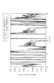
図4は、ドリフト補償用演算部46によってジャイロセンサ36からの信号群GSに基づく角速度の出力値についてドリフト補償演算がなされた場合の効果をあらわす特性線を示す。図4において、縦軸に角速度をとり、横軸に時間をとって示されており、特性線L1が、ドリフト補償演算がなされた場合を示し、特性線L2が、ドリフト補償演算が行われていない場合を示す。
FIG. 4 shows characteristic lines representing the effect when the drift compensation calculation is performed on the output value of the angular velocity based on the signal group GS from the
図4の特性線L1において、特性線L2に比して38秒近傍において明らかなように、角速度が確実に零近傍に収斂している。 In the characteristic line L1 of FIG. 4, the angular velocity is surely converged to near zero as clearly seen in the vicinity of 38 seconds as compared with the characteristic line L2.
なお、数8に示した演算方法に限定されるものではない。例えば、以下に示すいずれかの演算方法が採用できる。このほか、Vxyにかかる係数としては、 q3が0のとき1であり、かつq3に対して単調増加するものを採用できる。 Note that the present invention is not limited to the calculation method shown in Formula 8. For example, any of the following calculation methods can be employed. In addition, as a coefficient relating to Vxy, a coefficient that is 1 when q3 is 0 and monotonously increases with respect to q3 can be employed.
また、数11に示した演算方法に限定されるものではない。例えば、以下に示すいずれかの演算方法が採用できる。このほか、V´´zにかかる係数としては、 q3が0のとき1であり、かつq3に対して単調増加するものを採用できる。
Also, the calculation method shown in
また、内視鏡部内の撮像部のカメラ情報から、内視鏡部の先端部の移動速度を制御することができる。ここで、内視鏡部内の撮像部のカメラ情報は、カメラのズーム倍率である。 Further, the moving speed of the distal end portion of the endoscope unit can be controlled from the camera information of the imaging unit in the endoscope unit. Here, the camera information of the imaging unit in the endoscope unit is the zoom magnification of the camera.
速度制御用演算部48は、カメラのズーム倍率に応じて撮像部の速度を変更可能とするように調節するために目標速度ベクトルVxyに対し演算を行う。これにより、頭の回転による視界の移動量を調節できる。そのため操作の直感性が向上する。
The speed
また、速度制御用演算部48は、カメラのズーム倍率に応じて撮像部の速度を変更可能とするように調節するために目標速度ベクトルV´´zに対し演算を行う。この演算により、内視鏡の前後移動による視界の移動量を調節できる。そのため操作の直感性が向上する。
Further, the speed
また、上述の例において、万一、内視鏡24の撮像部が体内の臓器に接触した場合、安全性の観点からHMD30で手術者に知らせるとともに、本システムを自動停止させるように構成されてもよい。
In the above example, if the imaging unit of the
また、上述した説明では、頭部に固定された座標系から保持アームのローカル座標に変換したが、この方法に限定されるわけではない。座標系の取り方は任意なので、例えば頭の前後方向をy軸、上下方向をz軸に設定してもよい。また、座標変換を経ずにq4の計算と同様に、頭の角速度から直接q1、q2を算出してもよい。 In the above description, the coordinate system fixed to the head is converted into the local coordinates of the holding arm, but the present invention is not limited to this method. Since the method of taking the coordinate system is arbitrary, for example, the front-rear direction of the head may be set to the y-axis and the vertical direction may be set to the z-axis. Further, q1 and q2 may be calculated directly from the angular velocity of the head, similarly to the calculation of q4, without performing coordinate conversion.
したがって、本発明の一例においては、以下のような効果を奏する。
1.空気圧シリンダーなどの空気圧アクチュエータの駆動によって、受動的な柔らかさを実現し、過度な駆動力を生じない。また、柔らかさは、圧力の調整によって容易に実現できる。
2.内視鏡の一部が万一臓器等に接触した場合、接触力を空気圧アクチュエータの差圧から推定有することも可能である。
3.腹壁の挿入点が機構的に不動点となるように設計されている。スライダクランク機構によって空気圧シリンダーの直動運動を回転に変換し、上下方向の動作を実現し、左右、回転は、空気圧揺動アクチュエータで実現している。前後方向の動作は空気圧シリンダーの直動を用いて、合計4 自由度を実現できる。
Therefore, in the example of the present invention, the following effects can be obtained.
1. Passive softness is achieved by driving a pneumatic actuator such as a pneumatic cylinder, and no excessive driving force is generated. Softness can be easily realized by adjusting the pressure.
2. If a part of the endoscope contacts an organ or the like, the contact force can be estimated from the differential pressure of the pneumatic actuator.
3. It is designed so that the insertion point of the abdominal wall is mechanically fixed. The linear motion of the pneumatic cylinder is converted into rotation by the slider crank mechanism, and the vertical motion is realized, and the left and right and rotation are realized by the pneumatic swing actuator. A total of 4 degrees of freedom can be achieved using the linear motion of the pneumatic cylinder for the longitudinal movement.
なお、本発明は上述の発明を実施するための形態に限らず本発明の要旨を逸脱することなくその他種々の構成を採り得ることはもちろんである。 It is to be noted that the present invention is not limited to the embodiment for carrying out the above-described invention, and various other configurations can be adopted without departing from the gist of the present invention.
10 保持アームユニット
24 内視鏡
30 HMD
34 地磁気センサ
36 ジャイロセンサ
40 制御ユニット
46 ドリフト補償用演算部
48 速度制御用演算部
52 ズーム操作用フットスイッチ
60 内視鏡制御システム
10
34
Claims (5)
前記内視鏡部を回動、内視鏡軸まわりの自転(ロール)、および内視鏡軸方向の並進が可能に支持され、その姿勢情報を送出可能な保持アームユニット部と、
前記内視鏡部の前記撮像部からの画像信号に基づく画像を表示する表示部と、
操作者の首周りの姿勢状態を検出するセンサからなる姿勢検出部と、
制御ユニットとから構成される内視鏡操作システムにおいて、
前記姿勢検出部からの、首を中心軸線とした右向き(時計回り方向)の回転(右回旋)、首を中心軸線とした左向き(反時計回り方向)の回転(左回旋)、首に対し縦方向の回転(屈曲、伸展)、首に対し右方向への傾動(右側屈)、首に対し左方向への傾動(左側屈)の移動姿勢の動き情報を、前記センサで検出し、前記保持アームユニットの内視鏡を、それぞれ右回旋、左回旋、屈曲/伸展、右周りの自転、及び左周りの自転を行い、
前記保持アームユニットの前記姿勢情報と、前記内視鏡部内の前記撮像部のカメラ情報とから、前記内視鏡部の速度または角速度を制御し、
前記制御ユニットは、前記内視鏡部の先端の挿入量をあらわす係数に基づいて、前記内視鏡部の目標速度または目標角速度を算出することを特徴とする内視鏡操作システム。 An endoscope unit having an imaging unit at the tip, and
Rotation around rotation, the endoscope shaft said endoscope portion (rolls), and the translation of the endoscope axis direction is rotatably supported, and transmittable holding arm unit section the posture information,
A display unit for displaying an image based on an image signal from the imaging unit of the endoscope unit;
A posture detection unit comprising a sensor for detecting a posture state around the neck of the operator;
In an endoscope operation system composed of a control unit ,
From the posture detection unit, rotation (right rotation) in the right direction (clockwise direction) with the neck as the center axis, rotation (left rotation) in the left direction (counterclockwise direction) with the neck as the center axis, vertical to the neck Rotation direction (bending, stretching), tilting rightward with respect to the neck (bending right), and movement information of moving posture such as tilting left with respect to the neck (bending left) are detected by the sensor and retained. The arm unit endoscope is rotated clockwise, counterclockwise, bent / extended, rotated clockwise, and rotated counterclockwise.
From the posture information of the holding arm unit and the camera information of the imaging unit in the endoscope unit, the speed or angular velocity of the endoscope unit is controlled ,
The endoscope operation system , wherein the control unit calculates a target velocity or a target angular velocity of the endoscope unit based on a coefficient representing an insertion amount of the distal end of the endoscope unit .
Priority Applications (4)
| Application Number | Priority Date | Filing Date | Title |
|---|---|---|---|
| JP2012122489A JP5766150B2 (en) | 2012-05-29 | 2012-05-29 | Endoscope operation system |
| US14/404,341 US20150148594A1 (en) | 2012-05-29 | 2013-02-16 | Endoscope operation system |
| PCT/JP2013/053772 WO2013179693A1 (en) | 2012-05-29 | 2013-02-16 | Endoscope operation system |
| EP13797833.4A EP2856923A4 (en) | 2012-05-29 | 2013-02-16 | Endoscope operation system |
Applications Claiming Priority (1)
| Application Number | Priority Date | Filing Date | Title |
|---|---|---|---|
| JP2012122489A JP5766150B2 (en) | 2012-05-29 | 2012-05-29 | Endoscope operation system |
Publications (3)
| Publication Number | Publication Date |
|---|---|
| JP2013244377A JP2013244377A (en) | 2013-12-09 |
| JP2013244377A5 JP2013244377A5 (en) | 2015-01-08 |
| JP5766150B2 true JP5766150B2 (en) | 2015-08-19 |
Family
ID=49672909
Family Applications (1)
| Application Number | Title | Priority Date | Filing Date |
|---|---|---|---|
| JP2012122489A Expired - Fee Related JP5766150B2 (en) | 2012-05-29 | 2012-05-29 | Endoscope operation system |
Country Status (4)
| Country | Link |
|---|---|
| US (1) | US20150148594A1 (en) |
| EP (1) | EP2856923A4 (en) |
| JP (1) | JP5766150B2 (en) |
| WO (1) | WO2013179693A1 (en) |
Families Citing this family (13)
| Publication number | Priority date | Publication date | Assignee | Title |
|---|---|---|---|---|
| JP5737796B2 (en) * | 2013-03-29 | 2015-06-17 | 国立大学法人東京工業大学 | Endoscope operation system and endoscope operation program |
| JP2015156938A (en) | 2014-02-24 | 2015-09-03 | ソニー株式会社 | Image processing device and image processing method |
| KR101601021B1 (en) * | 2014-03-10 | 2016-03-08 | (주)아솔 | Three dimension endoscope system using giro sensor |
| WO2015146850A1 (en) | 2014-03-28 | 2015-10-01 | ソニー株式会社 | Robot arm device, and method and program for controlling robot arm device |
| KR101545654B1 (en) * | 2014-06-26 | 2015-08-20 | 주식회사 아이파이브 | Customized by individual exercise system and customized by individual exercise method |
| JPWO2017038241A1 (en) | 2015-08-28 | 2018-06-14 | 富士フイルム株式会社 | Device operating device, device operating method, and electronic device system |
| CN108471931A (en) * | 2016-02-12 | 2018-08-31 | 奥林巴斯株式会社 | Photographic device, stereo endoscope and stereoscopic endoscope system |
| EP3603476A4 (en) * | 2017-03-24 | 2020-03-25 | Sony Corporation | Medical system control device, medical system control method, and medical system |
| EP3612123A4 (en) * | 2017-04-20 | 2021-01-13 | Intuitive Surgical Operations, Inc. | Systems and methods for constraining a virtual reality surgical system |
| JP6965085B2 (en) * | 2017-10-05 | 2021-11-10 | キヤノン株式会社 | Operating device, system, and imaging device |
| AT522029B1 (en) * | 2018-12-19 | 2021-03-15 | Ronald Kefurt Dr | Camera motion control |
| US20200215376A1 (en) * | 2019-01-07 | 2020-07-09 | Spencer Bishop | Smartbell |
| JP7370007B2 (en) | 2020-02-21 | 2023-10-27 | 国立大学法人 長崎大学 | Endoscope operation support system and endoscope system |
Family Cites Families (17)
| Publication number | Priority date | Publication date | Assignee | Title |
|---|---|---|---|---|
| JP3540362B2 (en) * | 1994-06-14 | 2004-07-07 | オリンパス株式会社 | Surgical manipulator control system and control method |
| US5876325A (en) * | 1993-11-02 | 1999-03-02 | Olympus Optical Co., Ltd. | Surgical manipulation system |
| US5436542A (en) * | 1994-01-28 | 1995-07-25 | Surgix, Inc. | Telescopic camera mount with remotely controlled positioning |
| JP3506809B2 (en) * | 1995-06-08 | 2004-03-15 | オリンパス株式会社 | Body cavity observation device |
| JP3618413B2 (en) * | 1995-05-15 | 2005-02-09 | オリンパス株式会社 | Endoscope device |
| JP3628743B2 (en) * | 1995-02-22 | 2005-03-16 | オリンパス株式会社 | Medical manipulator |
| JP3986099B2 (en) * | 1995-05-02 | 2007-10-03 | オリンパス株式会社 | Surgical manipulator system |
| JP3717552B2 (en) * | 1995-09-01 | 2005-11-16 | オリンパス株式会社 | Medical manipulator system |
| JPH10309258A (en) | 1997-05-13 | 1998-11-24 | Olympus Optical Co Ltd | Body cavity examination device |
| JP2001145634A (en) * | 1999-11-19 | 2001-05-29 | Olympus Optical Co Ltd | Endoscope holder |
| JP2002136471A (en) * | 2000-10-30 | 2002-05-14 | Olympus Optical Co Ltd | Endoscope apparatus |
| JP4377827B2 (en) * | 2004-03-30 | 2009-12-02 | 株式会社東芝 | Manipulator device |
| JP4488312B2 (en) * | 2005-07-08 | 2010-06-23 | オリンパス株式会社 | Medical manipulator system |
| JP5327687B2 (en) * | 2007-03-01 | 2013-10-30 | 国立大学法人東京工業大学 | Maneuvering system with haptic function |
| JP5452813B2 (en) * | 2008-05-28 | 2014-03-26 | 国立大学法人東京工業大学 | Maneuvering system with haptic function |
| JP5814938B2 (en) * | 2010-01-08 | 2015-11-17 | コーニンクレッカ フィリップス エヌ ヴェKoninklijke Philips N.V. | Calibration-free visual servo using real-time speed optimization |
| JP5537204B2 (en) * | 2010-03-23 | 2014-07-02 | オリンパス株式会社 | Medical manipulator system |
-
2012
- 2012-05-29 JP JP2012122489A patent/JP5766150B2/en not_active Expired - Fee Related
-
2013
- 2013-02-16 US US14/404,341 patent/US20150148594A1/en not_active Abandoned
- 2013-02-16 WO PCT/JP2013/053772 patent/WO2013179693A1/en active Application Filing
- 2013-02-16 EP EP13797833.4A patent/EP2856923A4/en not_active Withdrawn
Also Published As
| Publication number | Publication date |
|---|---|
| WO2013179693A1 (en) | 2013-12-05 |
| EP2856923A4 (en) | 2016-02-24 |
| US20150148594A1 (en) | 2015-05-28 |
| JP2013244377A (en) | 2013-12-09 |
| EP2856923A1 (en) | 2015-04-08 |
Similar Documents
| Publication | Publication Date | Title |
|---|---|---|
| JP5766150B2 (en) | Endoscope operation system | |
| JP5737796B2 (en) | Endoscope operation system and endoscope operation program | |
| JP5846385B2 (en) | Endoscope operation system | |
| JP7248554B2 (en) | Systems and methods for controlling the orientation of an imaging instrument | |
| JP6026515B2 (en) | Estimating the position and orientation of the frame used to control the tool's movement | |
| WO2014073121A1 (en) | Manipulation system for manipulable device and manipulation input device | |
| WO2018159338A1 (en) | Medical support arm system and control device | |
| EP2822445B1 (en) | Overall endoscopic control system | |
| KR101705921B1 (en) | Synthetic representation of a surgical robot | |
| US8335590B2 (en) | System and method for adjusting an image capturing device attribute using an unused degree-of-freedom of a master control device | |
| CA3010896A1 (en) | Graphical user interface for a robotic surgical system | |
| JP7115493B2 (en) | Surgical arm system and surgical arm control system | |
| JP7480477B2 (en) | Medical observation system, control device and control method | |
| CN111991085A (en) | Surgical robot, graphical control device thereof and graphical display method | |
| EP2862497B1 (en) | Manipulator system | |
| WO2020054566A1 (en) | Medical observation system, medical observation device and medical observation method | |
| JP2022514635A (en) | Endoscope with dual image sensors | |
| JP6053358B2 (en) | Surgery support device | |
| CN111991084B (en) | Surgical robot, virtual imaging control method thereof and virtual imaging control device thereof | |
| JP2022048245A (en) | Imaging system and observation method | |
| JPH08196541A (en) | Manipulator for operation | |
| US20240062499A1 (en) | Image processing device, manipulator system, image processing method and display method | |
| WO2015110929A1 (en) | Robotic control of an endoscope orientation |
Legal Events
| Date | Code | Title | Description |
|---|---|---|---|
| A521 | Request for written amendment filed |
Free format text: JAPANESE INTERMEDIATE CODE: A523 Effective date: 20141117 |
|
| A621 | Written request for application examination |
Free format text: JAPANESE INTERMEDIATE CODE: A621 Effective date: 20141117 |
|
| A871 | Explanation of circumstances concerning accelerated examination |
Free format text: JAPANESE INTERMEDIATE CODE: A871 Effective date: 20141117 |
|
| A975 | Report on accelerated examination |
Free format text: JAPANESE INTERMEDIATE CODE: A971005 Effective date: 20141225 |
|
| A131 | Notification of reasons for refusal |
Free format text: JAPANESE INTERMEDIATE CODE: A131 Effective date: 20150127 |
|
| A521 | Request for written amendment filed |
Free format text: JAPANESE INTERMEDIATE CODE: A523 Effective date: 20150322 |
|
| TRDD | Decision of grant or rejection written | ||
| A01 | Written decision to grant a patent or to grant a registration (utility model) |
Free format text: JAPANESE INTERMEDIATE CODE: A01 Effective date: 20150520 |
|
| A61 | First payment of annual fees (during grant procedure) |
Free format text: JAPANESE INTERMEDIATE CODE: A61 Effective date: 20150616 |
|
| R150 | Certificate of patent or registration of utility model |
Ref document number: 5766150 Country of ref document: JP Free format text: JAPANESE INTERMEDIATE CODE: R150 |
|
| R250 | Receipt of annual fees |
Free format text: JAPANESE INTERMEDIATE CODE: R250 |
|
| LAPS | Cancellation because of no payment of annual fees |