JP5760465B2 - Virtual image display device - Google Patents
Virtual image display device Download PDFInfo
- Publication number
- JP5760465B2 JP5760465B2 JP2011022445A JP2011022445A JP5760465B2 JP 5760465 B2 JP5760465 B2 JP 5760465B2 JP 2011022445 A JP2011022445 A JP 2011022445A JP 2011022445 A JP2011022445 A JP 2011022445A JP 5760465 B2 JP5760465 B2 JP 5760465B2
- Authority
- JP
- Japan
- Prior art keywords
- light
- display device
- image
- light guide
- reflecting surface
- Prior art date
- Legal status (The legal status is an assumption and is not a legal conclusion. Google has not performed a legal analysis and makes no representation as to the accuracy of the status listed.)
- Active
Links
- 230000003287 optical effect Effects 0.000 claims description 117
- 230000005540 biological transmission Effects 0.000 claims description 13
- 239000011347 resin Substances 0.000 claims description 10
- 229920005989 resin Polymers 0.000 claims description 10
- 238000002347 injection Methods 0.000 claims description 7
- 239000007924 injection Substances 0.000 claims description 7
- 239000000463 material Substances 0.000 claims description 6
- 238000001746 injection moulding Methods 0.000 claims description 5
- 238000006116 polymerization reaction Methods 0.000 claims description 2
- 239000004973 liquid crystal related substance Substances 0.000 description 55
- 239000010410 layer Substances 0.000 description 26
- 238000010586 diagram Methods 0.000 description 12
- 238000005286 illumination Methods 0.000 description 12
- 210000001747 pupil Anatomy 0.000 description 11
- 238000002834 transmittance Methods 0.000 description 7
- 230000001154 acute effect Effects 0.000 description 6
- 229910052751 metal Inorganic materials 0.000 description 6
- 239000002184 metal Substances 0.000 description 6
- 239000011248 coating agent Substances 0.000 description 5
- 238000000576 coating method Methods 0.000 description 5
- 230000004907 flux Effects 0.000 description 5
- 230000004048 modification Effects 0.000 description 5
- 238000012986 modification Methods 0.000 description 5
- 230000002093 peripheral effect Effects 0.000 description 4
- 229920001187 thermosetting polymer Polymers 0.000 description 4
- 238000000465 moulding Methods 0.000 description 3
- 230000010287 polarization Effects 0.000 description 3
- 230000015572 biosynthetic process Effects 0.000 description 2
- 238000000151 deposition Methods 0.000 description 2
- 210000003128 head Anatomy 0.000 description 2
- 238000000034 method Methods 0.000 description 2
- 230000001902 propagating effect Effects 0.000 description 2
- 239000013585 weight reducing agent Substances 0.000 description 2
- 101100272626 Drosophila melanogaster BomBc1 gene Proteins 0.000 description 1
- 239000000853 adhesive Substances 0.000 description 1
- 230000001070 adhesive effect Effects 0.000 description 1
- 229910052782 aluminium Inorganic materials 0.000 description 1
- XAGFODPZIPBFFR-UHFFFAOYSA-N aluminium Chemical compound [Al] XAGFODPZIPBFFR-UHFFFAOYSA-N 0.000 description 1
- 230000000903 blocking effect Effects 0.000 description 1
- 230000015556 catabolic process Effects 0.000 description 1
- 239000003086 colorant Substances 0.000 description 1
- 239000002131 composite material Substances 0.000 description 1
- 230000007547 defect Effects 0.000 description 1
- 238000006731 degradation reaction Methods 0.000 description 1
- 230000006866 deterioration Effects 0.000 description 1
- 238000007598 dipping method Methods 0.000 description 1
- 230000001747 exhibiting effect Effects 0.000 description 1
- 239000011521 glass Substances 0.000 description 1
- 238000010030 laminating Methods 0.000 description 1
- 230000000644 propagated effect Effects 0.000 description 1
- 239000011241 protective layer Substances 0.000 description 1
- 238000005507 spraying Methods 0.000 description 1
- 238000003786 synthesis reaction Methods 0.000 description 1
- 238000011144 upstream manufacturing Methods 0.000 description 1
- 238000007740 vapor deposition Methods 0.000 description 1
Images


Classifications
-
- G—PHYSICS
- G02—OPTICS
- G02B—OPTICAL ELEMENTS, SYSTEMS OR APPARATUS
- G02B27/00—Optical systems or apparatus not provided for by any of the groups G02B1/00 - G02B26/00, G02B30/00
- G02B27/01—Head-up displays
- G02B27/017—Head mounted
- G02B27/0172—Head mounted characterised by optical features
-
- G—PHYSICS
- G02—OPTICS
- G02B—OPTICAL ELEMENTS, SYSTEMS OR APPARATUS
- G02B27/00—Optical systems or apparatus not provided for by any of the groups G02B1/00 - G02B26/00, G02B30/00
- G02B27/01—Head-up displays
- G02B27/0101—Head-up displays characterised by optical features
- G02B2027/0118—Head-up displays characterised by optical features comprising devices for improving the contrast of the display / brillance control visibility
-
- G—PHYSICS
- G02—OPTICS
- G02B—OPTICAL ELEMENTS, SYSTEMS OR APPARATUS
- G02B27/00—Optical systems or apparatus not provided for by any of the groups G02B1/00 - G02B26/00, G02B30/00
- G02B27/01—Head-up displays
- G02B27/0101—Head-up displays characterised by optical features
- G02B2027/0123—Head-up displays characterised by optical features comprising devices increasing the field of view
-
- G—PHYSICS
- G02—OPTICS
- G02B—OPTICAL ELEMENTS, SYSTEMS OR APPARATUS
- G02B27/00—Optical systems or apparatus not provided for by any of the groups G02B1/00 - G02B26/00, G02B30/00
- G02B27/01—Head-up displays
- G02B27/017—Head mounted
- G02B2027/0178—Eyeglass type
-
- G—PHYSICS
- G02—OPTICS
- G02B—OPTICAL ELEMENTS, SYSTEMS OR APPARATUS
- G02B6/00—Light guides; Structural details of arrangements comprising light guides and other optical elements, e.g. couplings
Landscapes
- Physics & Mathematics (AREA)
- General Physics & Mathematics (AREA)
- Optics & Photonics (AREA)
- Optical Elements Other Than Lenses (AREA)
Description
本発明は、頭部に装着して使用するヘッドマウントディスプレイ等の虚像表示装置に関する。 The present invention relates to a virtual image display device such as a head mounted display that is used by being mounted on a head.
近年、ヘッドマウントディスプレイのように虚像の形成及び観察を可能にする虚像表示装置として、導光板によって表示素子からの画像光を観察者の瞳に導くタイプのものが種々提案されている。 2. Description of the Related Art In recent years, various types of virtual image display devices capable of forming and observing virtual images such as a head-mounted display have been proposed that guide image light from a display element to an observer's pupil using a light guide plate.
このような虚像表示装置において、画像光と外界光とを重畳させるために、シースルー光学系の提案がなされている(特許文献1、2参照)。
In such a virtual image display device, a see-through optical system has been proposed to superimpose image light and external light (see
しかし、特許文献1等に記載の装置では、瞳サイズよりも射出開口が小さい導光光学系を用いる瞳分割方式によってシースルーを実現しているため、虚像の表示サイズを大きくすることが困難である。また、瞳サイズよりも小さい導光光学系を用いるため、人間の個々の眼幅に対応するために有効瞳径(虚像の取り込みを可能にする採光径であり、アイリング径とも呼ぶ)を大きくすることが困難である。また、物理的に瞳付近に導光光学系の射出開口や筐体が配置されるため、死角が生じてしまい完全なシースルーとはいえなくなる。
However, in the apparatus described in
なお、頭部装着ディスプレイ用の光学システムとして、導光角度の異なる複数の光モードを進行させることができる導光パイプを備えるものが存在する(特許文献3参照)。このような光学システムをおいて、射出側の第3光学面をハーフミラーとし第3光学面の透過光が直進するような工夫をすることで、シースルー型の表示装置にすることも考えられる。 There is an optical system for a head-mounted display that includes a light guide pipe that can advance a plurality of light modes having different light guide angles (see Patent Document 3). In such an optical system, it is conceivable to make a see-through display device by devising such that the third optical surface on the emission side is a half mirror and the transmitted light of the third optical surface goes straight.
しかし、特許文献3の光学システムでは、複数の光モードによる像が互いに位置ずれしていることを前提として、光モードごとに異なる入射角度に設定されたコリメート光で液晶パネルを照明する。そして、各光モードで表示内容を変更するとともに各光モードの表示をシーケンシャルに実行することで、各光モードの画像をつなぎ合わせて全体画像を得るようにしている。この場合、1つの液晶パネルによって、全体画像を構成する中央の画像と左右の画像とを時間差で変更しつつ表示しなければならず、虚像表示装置が複雑化し観察画像も暗くなる。 However, in the optical system of Patent Document 3, the liquid crystal panel is illuminated with collimated light set at different incident angles for each light mode on the premise that images in a plurality of light modes are displaced from each other. Then, the display contents are changed in each light mode and the display in each light mode is executed sequentially, so that images in the respective light modes are connected to obtain an entire image. In this case, the central image and the left and right images constituting the entire image must be displayed while being changed with a time difference by one liquid crystal panel, which complicates the virtual image display device and darkens the observation image.
以上とは別に、眼前を覆うような光射出部を有する導光部材によって外界光に重ねて虚像の観察を可能にする虚像表示装置であって、時間差で画像をつなぎ合わせる必要のないものも考えられるが、大きな画像を表示することは容易でなく、横の導光方向に関して画像に欠けや輝度斑が発生しやすい。 Apart from the above, a virtual image display device that enables observation of a virtual image superimposed on external light by a light guide member having a light emitting part that covers the front of the eye, which does not need to join images with a time difference However, it is not easy to display a large image, and the image is easily chipped and luminance spots are easily generated in the horizontal light guide direction.
本発明は、上記背景技術の問題に鑑みてなされたものであり、画像の欠けや輝度斑を抑制して高品位の虚像を表示できる虚像表示装置を提供することを目的とする。 The present invention has been made in view of the above problems of the background art, and an object of the present invention is to provide a virtual image display device capable of displaying a high-quality virtual image while suppressing image defects and luminance spots.
上記課題を解決するため、本発明に係る虚像表示装置は、(a)画像光を形成する画像表示装置と、(b)画像表示装置から射出された画像光を入射させる投射光学系と、(c)導光部と、導光部に画像光を入射させる光入射部と、導光部によって導かれた画像光を外部に射出させる光射出部とを有し、光射出部を介して画像光の観察を可能にする導光部材とを備え、(d)導光部は、互いに平行に配置され全反射による導光を可能にする第1反射面と第2反射面とを有し、(e)光入射部は、第1反射面に対して所定の角度をなす第3反射面を有し、(f)光射出部は、第1反射面に対して所定の角度をなす第4反射面を有し、(g)投射光学系は、第1反射面の平面と平行であり、第1反射面と第3反射面の交線に垂直な方向において、第3反射面の開口幅よりも広い射出開口幅を有し、前記射出開口幅の前記交線に垂直な方向の前記光射出部側の一方のエッジは、前記第3反射面の開口幅の前記第3反射面と前記第2反射面との境界から前記光射出部側に前記射出開口幅の他方のエッジより比較的大きくはみ出している。
In order to solve the above problems, a virtual image display device according to the present invention includes (a) an image display device that forms image light, (b) a projection optical system that makes the image light emitted from the image display device enter, c) a light guide unit, a light incident unit that causes the image light to enter the light guide unit, and a light emission unit that emits the image light guided by the light guide unit to the outside. A light guide member that enables observation of light, and (d) the light guide unit includes a first reflection surface and a second reflection surface that are arranged in parallel to each other and enable light guide by total reflection, (E) The light incident portion has a third reflection surface that forms a predetermined angle with respect to the first reflection surface, and (f) the light emission portion includes a fourth angle that forms a predetermined angle with respect to the first reflection surface. (G) the projection optical system is parallel to the plane of the first reflecting surface and is perpendicular to the line of intersection of the first reflecting surface and the third reflecting surface; 3 have a large exit opening width than the opening width of the reflecting surface, one edge of the light exit portion side in a direction perpendicular to the line of intersection of the injection opening width, the opening width of the third reflecting surface It protrudes relatively larger than the other edge of the exit opening width from the boundary between the third reflecting surface and the second reflecting surface to the light emitting part side .
上記虚像表示装置では、投射光学系が、導光に際して反射によって折り返される合成方向に関して第3反射面の開口幅よりも広い射出開口幅を有するので、投射光学系から射出された画像光が第3反射面に入射する際に、境界近くまで画像光GLを十分に入射させることができ部分的な欠けが生じることを防止でき、画像に欠けや大きな輝度斑が発生することを防止できる。 In the virtual image display device, the projection optical system has an exit aperture width wider than the aperture width of the third reflecting surface with respect to the composite direction that is folded back by reflection when the light is guided. Therefore, the image light emitted from the projection optical system is the third. When entering the reflecting surface, the image light GL can be sufficiently incident to the vicinity of the boundary, so that partial chipping can be prevented and chipping and large luminance spots can be prevented from occurring.
本発明の具体的な側面では、上記虚像表示装置において、投射光学系の最も光射出側のレンズから導光部材の第1反射面までの距離が例えば3mm以下である。この場合、投射光学系の最も光射出側のレンズから射出された画像光を、第1反射面を介して効率的に第2反射面に入射させることができる。 In a specific aspect of the present invention, in the virtual image display device, a distance from the most light emitting side lens of the projection optical system to the first reflecting surface of the light guide member is, for example, 3 mm or less. In this case, the image light emitted from the lens closest to the light emission side of the projection optical system can be efficiently incident on the second reflection surface via the first reflection surface.
本発明の別の側面では、投射光学系の射出開口幅は、第1反射面と第3反射面との交線に平行な第1の方向よりも、第1反射面と平行で第1反射面と第3反射面との交線に垂直な第2の方向において、小さくなっている。 In another aspect of the present invention, the exit aperture width of the projection optical system is parallel to the first reflection surface and is the first reflection rather than the first direction parallel to the intersection line of the first reflection surface and the third reflection surface. In the second direction perpendicular to the line of intersection between the surface and the third reflecting surface, it is smaller.
本発明のさらに別の側面では、画像表示装置の有効サイズが、第1の方向よりも第2の方向において大きくなっている。 In still another aspect of the present invention, the effective size of the image display device is larger in the second direction than in the first direction.
本発明の別の側面では、画像表示装置における第1部分領域から射出される第1画像光の導光部における反射回数と、導光に際して反射によって光路の折り返しが生じる閉じ込め方向に関して第1部分領域とは異なる第2部分領域から射出される第2画像光の導光部における反射回数とが、互いに異なる。この場合、反射回数の異なる画像光を利用することで、光射出部から射出される画像光の射出角度の角度幅を広くとることができる。つまり、画像表示装置における異なる部分領域からの画像光を比較的広い視野角で取り込むことができるようになり、光射出部越しに観察される虚像の表示サイズを大きく確保することができる。このように反射回数が異なる画像光を取り出す構造とすることにより、導光部をあまり厚くすることなく瞳を覆うように光射出部を大きくすることができる。なお、以上の閉じ込め方向は、板状の導光部内においては、第1反射面の平面と垂直であって、第1反射面と第3反射面の交線に垂直な方向を意味する。また、閉じ込め方向は、光入射部よりも光路的に上流側すなわち投射光学系等において、第1反射面の平面と平行であって、第1反射面と第3反射面の交線に垂直な方向に相当するものとなる。 In another aspect of the present invention, the first partial region in terms of the number of reflections of the first image light emitted from the first partial region in the image display device in the light guide and the confinement direction in which the optical path is turned back by the reflection during the light guide. The number of reflections of the second image light emitted from the second partial region different from the number of times of reflection in the light guide portion is different from each other. In this case, by using image light having a different number of reflections, it is possible to increase the angle width of the emission angle of the image light emitted from the light emitting unit. That is, image light from different partial areas in the image display device can be captured with a relatively wide viewing angle, and a large display size of the virtual image observed through the light emitting unit can be secured. By adopting a structure for extracting image light having different numbers of reflections in this way, the light emitting part can be enlarged so as to cover the pupil without making the light guide part too thick. The above confinement direction means a direction perpendicular to the plane of the first reflection surface and perpendicular to the intersection of the first reflection surface and the third reflection surface in the plate-like light guide. The confinement direction is upstream of the light incident portion on the optical path, that is, in the projection optical system or the like, parallel to the plane of the first reflecting surface and perpendicular to the intersection of the first reflecting surface and the third reflecting surface. It corresponds to the direction.
本発明のさらに別の側面では、閉じ込め方向が、投射光学系を通る第1光軸と第3反射面の法線とを含む断面に平行な方向である。上記断面方向に関して異なる位置からの画像光は、射出角度すなわち光入射部への入射角度を互いに異なるものとすることで、導光部における反射回数を異なるものとできる。 In still another aspect of the invention, the confinement direction is a direction parallel to a cross section including the first optical axis passing through the projection optical system and the normal line of the third reflecting surface. Image light from different positions with respect to the cross-sectional direction can be made to have a different number of reflections in the light guide portion by making the emission angle, that is, the incident angle to the light incident portion, different from each other.
本発明のさらに別の側面では、第4反射面に、ハーフミラーが施されており、第4反射面に対向する透過面を有する楔状の光透過部材をさらに備える。第4反射面と光透過部材とを介して外界光を瞳に導くことができ、外界の自然な観察が可能になる。 In still another aspect of the present invention, the fourth reflecting surface is further provided with a half mirror, and further includes a wedge-shaped light transmitting member having a transmitting surface facing the fourth reflecting surface. External light can be guided to the pupil via the fourth reflecting surface and the light transmitting member, and natural observation of the external environment is possible.
本発明のさらに別の側面では、光透過部材が、第1反射面と第2反射面とに対してそれぞれ平行に配置される第1面と第2面とを有する。これにより、光透過部材によるシースルー観察が歪みなく平坦性の高いものとなる。 In still another aspect of the present invention, the light transmissive member has a first surface and a second surface that are arranged in parallel to the first reflecting surface and the second reflecting surface, respectively. As a result, see-through observation with the light transmitting member has high flatness without distortion.
本発明のさらに別の側面では、導光部材は、射出成型によって独立して一体的に成型される。この場合、射出成型技術を利用して導光部材と光透過部材とを高精度で量産することができる。 In still another aspect of the present invention, the light guide member is independently and integrally molded by injection molding. In this case, the light guide member and the light transmissive member can be mass-produced with high accuracy using an injection molding technique.
本発明のさらに別の側面では、導光部材が、熱重合型の樹脂材料によって成型される。この場合、樹脂によって軽量化や安全性を高めることができ、熱硬化によって安定した高精度の成型が可能になる。 In still another aspect of the present invention, the light guide member is molded from a heat polymerization type resin material. In this case, weight reduction and safety can be increased by the resin, and stable and highly accurate molding can be performed by thermosetting.
以下、図面を参照しつつ、本発明の一実施形態に係る虚像表示装置について詳細に説明する。 Hereinafter, a virtual image display device according to an embodiment of the present invention will be described in detail with reference to the drawings.
〔A.虚像表示装置の外観〕
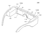
図1に示す実施形態の虚像表示装置100は、眼鏡のような外観を有するヘッドマウントディスプレイであり、この虚像表示装置100を装着した観察者に対して虚像による画像光を認識させることができるとともに、観察者に外界像をシースルーで観察させることができる。虚像表示装置100は、観察者の眼前を覆う光学パネル110と、光学パネル110を支持するフレーム121と、フレーム121のヨロイからテンプルにかけての部分に付加された第1及び第2駆動部131,132とを備える。ここで、光学パネル110は、第1パネル部分111と第2パネル部分112とを有し、両パネル部分111,112は、中央で一体的に連結された板状の部品となっている。図面上で左側の第1パネル部分111と第1駆動部131とを組み合わせた第1表示装置100Aは、左眼用の虚像を形成する部分であり、単独でも虚像表示装置として機能する。また、図面上で右側の第2パネル部分112と第2駆動部132とを組み合わせた第2表示装置100Bは、右眼用の虚像を形成する部分であり、単独でも虚像表示装置として機能する。なお、第1駆動部131と第2駆動部132とは、遮光用及び保護用のケース141に個別に収納されている。
[A. Appearance of virtual image display device)
A virtual
〔B.表示装置の構造〕
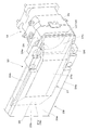
図2(A)等に示すように、第1表示装置100Aは、画像形成装置10と、導光装置20とを備える。ここで、画像形成装置10は、図1における第1駆動部131に相当し、導光装置20は、図1における第1パネル部分111に相当する。画像形成装置10については、図1におけるケース141を除いた本体部分を図示している。図2(A)において、導光装置20の部分は、図2(B)のAA矢視断面図となっている。なお、図1に示す第2表示装置100Bは、第1表示装置100Aと同様の構造を有し左右を反転させただけであるので、第2表示装置100Bの詳細な説明は省略する。
[B. Display device structure]
As shown in FIG. 2A and the like, the
画像形成装置10は、画像表示装置11と、投射光学系12とを有する。このうち、画像表示装置11は、2次元的な照明光SLを射出する照明装置31と、透過型の空間光変調装置である液晶表示デバイス32と、照明装置31及び液晶表示デバイス32の動作を制御する駆動制御部34とを有する。
The
照明装置31は、赤、緑、青の3色を含む光を発生する光源31aと、光源31aからの光を拡散させて矩形断面の光束にするバックライト導光部31bとを有する。液晶表示デバイス32は、照明装置31からの照明光SLを空間的に変調して動画像等の表示対象となるべき画像光を形成する。駆動制御部34は、光源駆動回路34aと、液晶駆動回路34bとを備える。光源駆動回路34aは、照明装置31の光源31aに電力を供給して安定した輝度の照明光SLを射出させる。液晶駆動回路34bは、液晶表示デバイス32に対して画像信号又は駆動信号を出力することにより、透過率パターンとして動画や静止画の元になるカラーの画像光を形成する。なお、液晶駆動回路34bに画像処理機能を持たせることができるが、外付けの制御回路に画像処理機能を持たせることもできる。投射光学系12は、液晶表示デバイス32上の各点から射出された画像光を平行状態の光束にするコリメートレンズである。
The illuminating
液晶表示デバイス32において、第1方向D1は、投射光学系12を通る第1光軸AX1と、後述する導光部材21の第3反射面21cに平行な特定線とを含む縦断面の延びる方向に対応し、第2方向D2は、上記第1光軸AX1と、上記第3反射面21cの法線とを含む横断面の延びる方向に対応する。言い換えれば、第1方向D1は、後述する導光部材21の第1反射面21aと第3反射面21cとの交線に平行な方向であり、第2方向D2は、上記第1反射面21aの平面と平行であり、上記第1反射面21aと第3反射面21cとの交線に垂直な方向となっている。つまり、液晶表示デバイス32の位置において、第1方向D1は、縦のY方向に相当し、第2方向D2は、横のX方向に相当する。ここで、液晶表示デバイス32の縦の第1方向D1における有効サイズES1は、液晶表示デバイス32の横の第2方向D2における有効サイズES2よりも小さくなっている(図2(B)等参照)。つまり、液晶表示デバイス32の表示領域DAは、横長となっている。
In the liquid
投射光学系12は、3つのレンズ群L1〜L3を有しており、これらのレンズ群L1〜L3は、鏡筒12a内に支持されている。鏡筒12aは、図1のケース141内に収納させている。鏡筒12aに支持された各レンズ群L1〜L3は、複数の樹脂製のレンズ等を組み合わせたものであり、第1光軸AX1に垂直な第1方向D1と第2方向D2とでサイズが異なったものとなっている。ただし、各レンズ群L1〜L3を構成する各レンズの光学面は、第1光軸AX1のまわりに回転対称な球面又は非球面形状を有しており、第1方向D1の集光特性と第2方向D2の集光特性とに特別な差を設けていない。レンズ群L1〜L3を収納する鏡筒12aの最も光射出側の射出開口EAには、図3にも示すように、レンズ群L3の光学面12fが露出している。ここで、射出開口EAの第1方向D1の射出開口幅E1は、射出開口EAの第2方向D2の射出開口幅E2よりも大きくなっている(図2(B)等参照)。つまり、投射光学系12の射出開口EAは、縦長となっている。これは、後述するように、縦の第1方向D1すなわちY方向に関しては、画像光GLを比較的広い光束幅としても画像光GLを導光装置20に入射させることができるが、横の第2方向D2に関しては、比較的狭い光束幅としなければ画像光GLを導光装置20に入射させることができないからである。
The projection
導光装置20は、導光部材21と光透過部材23とを接合したものであり、全体としてXY面に平行に延びる平板状の光学部材を構成している。
The
導光装置20のうち、導光部材21は、平面視において台形のプリズム状部材であり、側面として、第1反射面21aと、第2反射面21bと、第3反射面21cと、第4反射面21dとを有する。また、導光部材21は、第1、第2、第3、及び第4反射面21a,21b,21c,21dに隣接するとともに互いに対向する上面21eと下面21fとを有する。ここで、第1及び第2反射面21a,21bは、XY面に沿って延び、導光部材21の厚みtだけ離間する。また、第3反射面21cは、XY面に対して45°以下の鋭角αで傾斜しており、第4反射面21dは、XY面に対して例えば45°以下の鋭角βで傾斜している。第3反射面21cを通る第1光軸AX1と第4反射面21dを通る第2光軸AX2とは平行に配置され距離Dだけ離間している。なお、以下に詳述するが、第1反射面21aと第3反射面21cとの間には、稜を除去するように端面21hが設けられている。また、第1反射面21aと第4反射面21dとの間には、稜を除去するように端面21iが設けられている。導光部材21は、これらの端面21h,21iも含めると、8面の多面体状の外形を有するものとなっている。
In the
導光部材21は、第1及び第2反射面21a,21bによる全反射を利用して導光を行うものであり、導光に際して反射によって折り返される方向と、導光に際して反射によって折り返されない方向とがある。導光部材21で導光される画像について考えた場合、導光に際して複数回の反射によって折り返される横方向すなわち閉じ込め方向は、第1及び第2反射面21a,21bに垂直(Z軸に平行)で、後述するように光源側まで光路を展開した場合に、液晶表示デバイス32の第2方向D2に相当するものとなり、導光に際して反射によって折り返されない縦方向すなわち自由伝搬方向は、第1及び第2反射面21a,21b及び第3反射面21cに平行(Y軸に平行)で、後述するように光源側まで光路を展開した場合に、液晶表示デバイス32の第1方向D1に相当する。
The
導光部材21は、可視域で高い光透過性を示す樹脂材料で形成されている。導光部材21は、射出成型によって一体的に成型されたブロック状部材であり、例えば熱重合型の樹脂材料を成型金型内に射出させ熱硬化させることで形成されている。このように導光部材21は、一体形成品であるが、機能的に、光入射部B1と導光部B2と光射出部B3とに分けて考えることができる。
The
光入射部B1は、三角プリズム状の部分であり、第1反射面21aの一部である光入射面ISと、光入射面ISに対向する第3反射面21cとを有する。光入射面ISは、画像形成装置10からの画像光GLを取り込むための裏側又は観察者側の平面であり、投射光学系12に対向してその第1光軸AX1に垂直に延びている。第3反射面21cは、光入射面ISを通過した画像光GLを反射して導光部B2内に導くための矩形の全反射ミラーである。
The light incident part B1 is a triangular prism-shaped part, and includes a light incident surface IS that is a part of the first
図4(A)は、第3反射面21cを説明する図であり、光入射部B1における表面部分P1の部分拡大断面図である。第3反射面21cは、ミラー層25を有し保護層26で被覆されている。このミラー層25は、全反射のコーティングであり、導光部材21の斜面RS上にアルミ等の蒸着によって成膜を施すことにより形成される。第3反射面21cは、投射光学系12の第1光軸AX1又はXY面に対して例えば鋭角α=25°〜27°で傾斜しており、光入射面ISから入射し全体として+Z方向に向かう画像光GLを、全体として−Z方向寄りの−X方向に向かわせるように折り曲げることで、画像光GLを導光部B2内に確実に結合させる。
FIG. 4A is a diagram illustrating the third reflecting
図2(A)等に戻って、第3反射面21cは、略矩形の平面である。ここで、縦の第1方向D1における第3反射面21cの有効な開口幅F1は、投射光学系12の第1方向D1における射出開口幅E1と略等しいものとなっている。一方、横の第2方向(閉じ込め方向)D2における第3反射面21cの有効な開口幅F2は、投射光学系12の第2方向(閉じ込め方向)D2における射出開口幅E2よりも狭くなっている。つまり、投射光学系12は、その横の射出開口幅E2を第3反射面21cの開口幅F2よりも大きくすることで、画像光GLが第3反射面21cのX方向の周辺部まで入射するようにしている。第3反射面21cのX方向の開口幅F2は、具体的な実施例において例えば18mm程度とされており、投射光学系12のX方向の射出開口幅E2は、具体的な実施例において例えば19mm程度かそれ以上とされている。ここで、図2(B)に示すように、投射光学系12の射出開口EAのうち導光部B2寄りである−X側のエッジEG1の方が、第3反射面21cと第2反射面21bとの境界BAから比較的大きくはみ出しており、射出開口EAのうち導光部B2から離れた+X側のエッジEG2の方が、第3反射面21cと第1反射面21aとの境界に設けた端面21hから比較的小さくはみ出している。これは、投射光学系12から見ると、境界BAの方が端面21hよりも距離的に離れており、境界BA近くまで画像光GLを十分に入射させることができるように考慮したものである。
Returning to FIG. 2A and the like, the third reflecting
なお、投射光学系12の最も光射出側のレンズ群L3の光学面12fから光入射部B1の光入射面IS又は第1反射面21aまでの距離GAは、例えば3mm以下に設定されている。このように投射光学系12を光入射面ISに近接させることで、投射光学系12の最も光射出側のレンズ群L3から射出された画像光GLを、光入射面ISを介して効率的に第2反射面21cに入射させることができる。
The distance GA from the
導光部B2は、互いに対向しXY面に平行に延びる2平面として、光入射部B1で折り曲げられた画像光をそれぞれ全反射させる第1反射面21aと第2反射面21bとを有している。第1及び第2反射面21a,21bの間隔すなわち導光部材21の厚みtは、例えば9mm程度とされている。ここでは、第1反射面21aが画像形成装置10に近い裏側又は観察者側にあるものとし、第2反射面21bが画像形成装置10から遠い表側又は外界側にあるものとする。この場合、第1反射面21aは、上記の光入射面ISや後述する光射出面OSと共通の面部分となっている。第1及び第2反射面21a,21bは、屈折率差を利用する全反射面であり、ミラー層等の反射コートが施されていない。
The light guide B2 has first and second reflecting
図3(B)は、第1反射面21aを説明する図であり、導光部材21の導光部B2における表面部分P1の部分拡大断面図である。また、図3(C)は、第1反射面21aを説明する図であり、導光部材21の導光部B2における表面部分P1の部分拡大断面図である。第1及び第2反射面21a,21bは、表面の損傷を防止し映像の解像度低下を防止するため、ハードコート層27で被覆されている。このハードコート層27は、導光部材21の平坦面FS上にUV硬化性樹脂や熱硬化性樹脂等をディップ処理やスプレーコート処理によって成膜することによって形成される。光入射部B1の第3反射面21cで反射された画像光GLは、まず、第1反射面21aに入射し、全反射される。次に、当該画像光GLは、第2反射面21bに入射し、全反射される。以下この動作が繰り返されることで、画像光は、導光装置20の奥側即ち光射出部B3を設けた−X側に導かれる。なお、第1及び第2反射面21a,21bには反射コートが施されていないため、外界側から第2反射面21bに入射する外界光又は外光は、高い透過率で導光部B2を通過する。つまり、導光部B2は、外界像の透視が可能なシースルータイプになっている。
FIG. 3B is a diagram illustrating the first reflecting
以上の第1及び第2反射面21a,21bでの全反射は、ハードコート層27の屈折率の設定によっており、ハードコート層27の表面SSの内側で生じさせることができるが、平坦面FSの内側で生じさせることもできる。
The total reflection on the first and second reflecting
図2(A)等に戻って、光射出部B3は、三角プリズム状の部分であり、第1反射面21aの一部である光射出面OSと、光射出面OSに対向する第4反射面21dとを有する。光射出面OSは、画像光GLを観察者の眼EYに向けて射出するための裏側の平面であり、光入射面ISと同様に第1反射面21aの一部となっており、第2光軸AX2に垂直に延びている。光射出部B3を通る第2光軸AX2と光入射部B1を通る第1光軸AX1との距離Dは、観察者の頭部の幅等を考慮して例えば50mmに設定されている。第4反射面21dは、第1及び第2反射面21a,21bを経て入射してきた画像光GLを反射して光射出部B3外に射出させるための略矩形の平坦面である。第4反射面21dには、ハーフミラー層28が付随している。このハーフミラー層28は、光透過性を有する反射膜(すなわち半透過反射膜)であり、その表面は半透過反射面となっている。ハーフミラー層(光透過性の反射膜)28は、導光部材21の斜面RS上に金属反射膜や誘電体多層膜を成膜することにより形成される。ハーフミラー層28の画像光GLに対する反射率は、シースルーによる外界光GL'の観察を容易にする観点で、想定される画像光GLの入射角範囲において10%以上50%以下とする。具体的な実施例のハーフミラー層28の画像光GLに対する反射率は、例えば20%に設定され、画像光GLに対する透過率は、例えば80%に設定される。
Returning to FIG. 2A and the like, the light emission part B3 is a triangular prism-like part, and a light emission surface OS that is a part of the
図3(D)は、第4反射面21d及びその周辺の構造を説明する図であり、ハーフミラー層(光透過性の反射膜)28の断面の拡大図を付随させている。図からも明らかなように、ハーフミラー層(反射膜)28は、偏光特性を有しない金属反射膜28aと、偏光特性を有する第1誘電体多層膜28bと、偏光特性を有する第2誘電体多層膜28cとを含む。ここで、金属反射膜28aは、第1誘電体多層膜28bと第2誘電体多層膜28cとの間に挟まれている。つまり、ハーフミラー層28は、金属反射膜28aを中央に配置したサンドイッチ構造を有している。金属反射膜28aは、例えばAg膜、Al膜等である。下側の第1誘電体多層膜28bや上側の第2誘電体多層膜28cは、透明な誘電体層を数層以上積層したものであり、金属反射膜28aの角度特性等を改善する。これらの誘電体多層膜28b,28cについては省略することもできる。
FIG. 3D is a view for explaining the structure of the fourth reflecting
図2(B)等に戻って、第4反射面21dは、第1反射面21aに垂直な第2光軸AX2又はXY面に対して例えば鋭角α=25°〜27°で傾斜しており、上記ハーフミラー層28により、導光部B2の第1及び第2反射面21a,21bを経て入射してきた画像光GLを部分的に反射して全体として−Z方向に向かわせるように折り曲げることで、光射出面OSを通過させる。なお、第4反射面21dを透過した画像光GLは、光透過部材23に入射し、映像の形成には利用されない。
Returning to FIG. 2B and the like, the fourth reflecting
フレーム部分29は、光透過部23と、上側支持部材24bと、下側支持部材24cとを有している。これらのうち、上下一対の上側支持部材24bと下側支持部材24cとは、左側の導光部材21を上下から挟んで光透過部23に固定している。これらの支持部材24b,24cと光透過部23との協働により、導光部材21は、光透過部23に対して、上下のY方向に関してだけでなく、左右のX方向及び前後のZ方向に関しても正確に位置決めされて固定される。
The
光透過部材23は、導光部材21の本体と同一の屈折率を有し、第1面23aと、第2面23bと、第3面23cとを有する。第1及び第2面23a,23bは、XY面に沿って延びる。また、第3面23cは、XY面に対して傾斜しており、導光部材21の第4反射面21dに対向して平行に配置されている。つまり、光透過部材23は、第2面23bと第3面23cとに挟まれた楔状の部分23mを有する部材となっている。光透過部材23は、導光部材21と同様に、可視域で高い光透過性を示す樹脂材料で形成されている。光透過部材23は、射出成型によって一体的に成型されたブロック状部材であり、例えば熱重合型の樹脂材料を成型金型内に射出させ熱硬化させることで形成されている。
The
光透過部材23において、第1面23aは、導光部材21に設けた第1反射面21aの延長平面上に配置され、観察者の眼EYに近い裏側にあり、第2面23bは、導光部材21に設けた第2反射面21bの延長平面上に配置され、観察者の眼EYから遠い表側にある。第3面23cは、接着剤によって導光部材21の第4反射面21dに接合される矩形の透過面である。以上の第1面23aと第3面23cとなす角度は、導光部材21の第2反射面21bと第4反射面21dとのなす角度εと等しくなっており、第2面23bと第3面23cとなす角度は、導光部材21の第1反射面21aと第3反射面21cとのなす角度βと等しくなっている。
In the
光透過部材23と導光部材21とは、両者の接合部分及びその近傍において、観察者の眼前に対向する部位において、透視部B4を構成している。光透過部材23のうち、互いに鋭角を成す第2面23bと第3面23cとに挟まれて−X方向に広がる楔状の部材23mは、同様に楔状の光射出部B3と接合されることにより、全体として平板状の透視部B4におけるX方向に関する中央部分を構成する。第1及び第2面23a,23bには、ミラー層等の反射コートが施されていないため、導光部材21の導光部B2と同様に外界光GL'を高い透過率で透過させる。第3面23cも、外界光GL'を高い透過率で透過可能であるが、導光部材21の第4反射面21dがハーフミラー層28を有していることから、第3面23cを通過する外界光GL'は、例えば20%減光される。つまり、観察者は、20%に減光された画像光GLと80%に減光された外界光GL'とを重畳させたものを観察することになる。
The
上側支持部材24bの端部と下側支持部材24cの端部とにそれぞれ設けた連結部24e,24fは、投射光学系12の鏡筒12aをフレーム部分29に固定するために用いられるだけでなく、図1のケース141を取り付けるために利用される。
The connecting
〔C.画像光の光路の概要〕
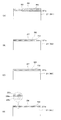
図5(A)は、液晶表示デバイス32の縦断面CS1に対応する第1方向D1の光路を説明する図である。第1方向D1に沿った縦断面すなわちYZ面(展開後のY'Z'面)において、液晶表示デバイス32から射出された画像光のうち、図中一点鎖線で示す表示領域32bの上端側(+Y側)から射出される成分を画像光GLaとし、図中二点差線で示す表示領域32bの下端側(−Y側)から射出される成分を画像光GLbとする。
[C. Overview of optical path of image light)
FIG. 5A is a diagram illustrating an optical path in the first direction D1 corresponding to the longitudinal section CS1 of the liquid
上側の画像光GLaは、投射光学系12によって平行光束化され、展開された光軸AX'に沿って、導光部材21の光入射部B1、導光部B2、及び光射出部B3を通り、観察者の眼EYに対して平行光束状態で、角度φ1の上方向から傾いて入射する。一方、下側の画像光GLbは、投射光学系12によって平行光束化され、展開された光軸AX'に沿って、導光部材21の光入射部B1、導光部B2、及び光射出部B3を通り、観察者の眼EYに対して平行光束状態で、角度φ2(|φ2|=|φ1|)の下方向から傾いて入射する。以上の角度φ1,φ2は、上下の半画角に相当し、例えば6.5°に設定される。
The upper image light GLa is converted into a parallel light flux by the projection
図5(B)は、液晶表示デバイス32の横断面CS2に対応する第2方向(閉じ込め方向)D2の光路を説明する図である。第2方向(閉じ込め方向又は合成方向)D2に沿った横断面すなわちXZ面(展開後のX'Z'面)において、液晶表示デバイス32から射出された画像光のうち、図中一点鎖線で示す表示領域32bに向かって右端側(+X側)の第1表示点P1から射出される成分を画像光GLcとし、図中二点差線で示す表示領域32bに向かって左端側(−X側)の第2表示点P2から射出される成分を画像光GLdとする。図5(B)中には、参考のため、右寄り内側から射出される画像光GLeと、左寄り内側から射出される画像光GLfとを追加している。
FIG. 5B is a diagram illustrating an optical path in the second direction (confinement direction) D2 corresponding to the cross section CS2 of the liquid
右側の第1表示点P1からの画像光GLcは、投射光学系12によって平行光束化され、展開された光軸AX'に沿って、導光部材21の光入射部B1、導光部B2、及び光射出部B3を通り、観察者の眼EYに対して平行光束状態で、角度θ1の右方向から傾いて入射する。一方、左側の第2表示点P2からの画像光GLdは、投射光学系12によって平行光束化され、展開された光軸AX'に沿って、導光部材21の光入射部B1、導光部B2、及び光射出部B3を通り、観察者の眼EYに対して平行光束状態で、角度θ2(|θ2|=|θ1|)の左方向から傾いて入射する。以上の角度θ1,θ2は、左右の半画角に相当し、例えば10°に設定される。
The image light GLc from the first display point P1 on the right side is converted into a parallel light beam by the projection
なお、第2方向D2の横方向に関しては、導光部材21中で画像光GLc,GLdが反射によって折り返され、反射の回数も異なることから、各画像光GLc,GLdが導光部材21中で不連続に表現されている。また、観察者の眼EYについては、図2(A)の場合と比較して見ている方向が上下反対となっている。結果的に、横方向に関しては、全体として画面が左右反転するが、後に詳述するように導光部材21を高精度に加工することで、液晶表示デバイス32の右半分の画像と液晶表示デバイス32の左半分の画像とが切れ目なく連続してズレなくつなぎ合わされたものとなる。なお、両画像光GLc,GLdの導光部材21内での反射回数が互いに異なることを考慮して、右側の画像光GLcの射出角度θ1'と左側の画像光GLdの射出角度θ2'とは異なるものに設定されている。
Note that, in the horizontal direction of the second direction D2, the image lights GLc and GLd are folded back by reflection in the
以上により、観察者の眼EYに入射する画像光GLa,GLb,GLc,GLdは、無限遠からの虚像となっており、縦の第1方向D1に関しては液晶表示デバイス32に形成された映像が正立し、横の第2方向D2に関しては液晶表示デバイス32に形成された映像が反転する。
As described above, the image lights GLa, GLb, GLc, and GLd incident on the observer's eye EY are virtual images from infinity, and the image formed on the liquid
〔D.横方向に関する画像光の光路〕
図6は、第1表示装置100Aにおける具体的な光路を説明する断面図である。投射光学系12は、3つのレンズL1,L2,L3を有している。
[D. (The optical path of image light in the horizontal direction)
FIG. 6 is a cross-sectional view illustrating a specific optical path in the
液晶表示デバイス32の右側の第1表示点P1からの画像光GL11,GL12は、投射光学系12のレンズL1,L2,L3を通過することで平行光束化され、導光部材21の光入射面ISに入射する。導光部材21内に導かれた画像光GL11,GL12は、第1及び第2反射面21a,21bにおいて等しい角度で全反射を繰り返して、最終的に光射出面OSから平行光束として射出される。具体的には、画像光GL11,GL12は、平行光束として導光部材21の第3反射面21cで反射された後、第1反射角γ1で導光部材21の第1反射面21aに入射し、全反射される(第1回目の全反射)。その後、画像光GL11,GL12は、第1反射角γ1を保った状態で、第2反射面21bに入射して全反射され(第2回目の全反射)、次いで再度第1反射面21aに入射して全反射される(第3回目の全反射)。結果的に、画像光GL11,GL12は、第1反射角γ1を保った状態で、第1及び第2反射面21a,21bで全反射を繰り返す。画像光GL11,GL12は、第1及び第2反射面21a,21bにおいて計3回全反射され、第4反射面21dに入射する。画像光GL11,GL12は、この第4反射面21dで第3反射面21cと同一の角度で反射され、光射出面OSからこの光射出面OSに垂直な第2光軸AX2方向に対して角度θ1の傾きで平行光束として射出される。
The image lights GL11 and GL12 from the first display point P1 on the right side of the liquid
液晶表示デバイス32の左側の第2表示点P2からの画像光GL21,GL22は、投射光学系12のレンズL1,L2,L3を通過することで平行光束化され、導光部材21の光入射面ISに入射する。導光部材21内に導かれた画像光GL21,GL22は、第1及び第2反射面21a,21bにおいて等しい角度で全反射を繰り返して、最終的に光射出面OSから平行光束として射出される。具体的には、画像光GL21,GL22は、平行光束として導光部材21の第3反射面21cで反射された後、第2反射角γ2(γ2<γ1)で導光部材21の第1反射面21aに入射し、全反射される(第1回目の全反射)。その後、画像光GL21,GL22は、第2反射角γ2を保った状態で、第2反射面21bに入射して全反射され(第2回目の全反射)、再度第1反射面21aに入射して全反射され(第3回目の全反射)、再度第2反射面21bに入射して全反射され(第4回目の全反射)、再々度第1反射面21aに入射して全反射される(第5回目の全反射)。結果的に、画像光GL21,GL22は、第1及び第2反射面21a,21bにおいて計5回全反射され、第4反射面21dに入射する。画像光GL21,GL22は、この第4反射面21dで第3反射面21cと同一の角度で反射され、光射出面OSからこの光射出面OSに垂直な第2光軸AX2方向に対して角度θ2の傾きで平行光束として射出される。
The image lights GL21 and GL22 from the second display point P2 on the left side of the liquid
図6において、導光部材21を展開した場合に第1反射面21aに対応する仮想的な第1面121aと、導光部材21を展開した場合に第2反射面21bに対応する仮想的な第2面121bとを描いている。このように展開することにより、第1表示点P1からの画像光GL11,GL12は、光入射面ISに対応する入射等価面IS'を通過した後、第1面121aを2回通過し第2面121bを1回通過して光射出面OSから射出されて観察者の眼EYに入射することが分かり、第2表示点P2からの画像光GL21,GL22は、光入射面ISに対応する入射等価面IS"を通過した後、第1面121aを3回通過し第2面121bを2回通過して光射出面OSから射出されて観察者の眼EYに入射することが分かる。見方を変えると、観察者は、2つの位置の異なる入射等価面IS',IS"の近傍に存在する投射光学系12のレンズL3を重ねて観察していることになる。
In FIG. 6, when the
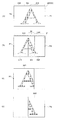
図7(A)は、液晶表示デバイス32の表示面を概念的に説明する図であり、図7(B)は、観察者に見える液晶表示デバイス32の虚像を概念的に説明する図であり、図7(C)及び7(D)は、虚像を構成する部分画像を説明する図である。図7(A)に示す液晶表示デバイス32に設けた矩形の画像形成領域ADは、図7(B)に示す虚像表示領域AIとして観察される。虚像表示領域AIの左側には、液晶表示デバイス32の画像形成領域ADのうち中央から右側にかけての部分に相当する第1投射像IM1が形成され、この第1投射像IM1は、図7(C)に示すように右側が欠けた部分画像となっている。また、虚像表示領域AIの右側には、液晶表示デバイス32の画像形成領域ADのうち中央から左側にかけての部分に相当する投射像IM2が虚像として形成され、この第2投射像IM2は、図7(D)に示すように左側が欠けた部分画像となっている。
7A is a diagram for conceptually explaining the display surface of the liquid
図7(A)に示す液晶表示デバイス32のうち第1投射像(虚像)IM1のみを形成する第1部分領域A10は、例えば液晶表示デバイス32の右端の第1表示点P1を含んでおり、導光部材21の導光部B2において合計3回全反射される画像光GL11,GL12を射出する。液晶表示デバイス32のうち第2投射像(虚像)IM2のみを形成する第2部分領域A20は、例えば液晶表示デバイス32の左端の第2表示点P2を含んでおり、導光部材21の導光部B2において合計5回全反射される画像光GL21,GL22を射出する。液晶表示デバイス32の画像形成領域ADの中央寄りにおいて第1及び第2部分領域A10,A20に挟まれて縦長に延びる帯域SAからの画像光は、図7(B)に示す重複画像ISを形成している。つまり、液晶表示デバイス32の帯域SAからの画像光は、導光部B2において計3回全反射される画像光GL11,GL12によって形成される第1投射像IM1と、導光部B2において計5回全反射される画像光GL11,GL12によって形成される第2投射像IM2となって、虚像表示領域AI上で重畳していることになる。導光部材21の加工が精密で、投射光学系12によって正確にコリメートされた光束が形成されているならば、重複画像ISについて、2つの投射像IM1,IM2の重畳によるズレや滲みを防止することができる。
The first partial area A10 that forms only the first projection image (virtual image) IM1 in the liquid
〔E.画像の劣化防止〕
以下、図7(B)に示す重複画像IS等における画像の劣化について説明する。重複画像ISは、図7(C)に示す第1投射像IM1の周辺部と、図7(D)に示す第2投射像IM2の周辺部とを重ね合わせたものと考えることができ、投射光学系12の画角サイズが小さい場合、周辺でケラレと呼ばれる部分的遮光が生じる。本実施形態の画像形成装置10の場合、上記の画像形成領域ADの中央は、重複画像ISであり光量の加算があるにも関わらず、第1及び第2投射像IM1,IM2の周辺減光によって、輝度低下が生じやすい。さらに、本実施形態の画像形成装置10の場合、重複画像ISを形成する画像光GLは、投射光学系12の射出開口EAのうち第2方向D2の両端側から射出される傾向が高い。
[E. (Preventing image deterioration)
Hereinafter, image degradation in the overlapping image IS shown in FIG. 7B will be described. The overlapping image IS can be considered as a superposition of the peripheral portion of the first projection image IM1 shown in FIG. 7C and the peripheral portion of the second projection image IM2 shown in FIG. When the field angle size of the
図8は、重複画像ISを形成する画像光GLが投射光学系12の射出開口EAのうち第2方向D2の両端側から射出される傾向が高い理由を説明する図である。第2方向(閉じ込め方向)D2に沿った横断面において、液晶表示デバイス32の中央から射出された画像光のうち、図中一点鎖線で示す+X側に傾いた成分を画像光GL31,GL32とし、液晶表示デバイス32の中央から射出された画像光のうち、図中一点鎖線で示す−X側に傾いた成分を画像光GL41,GL42とする。前者の画像光GL31,GL32は、第2光軸AX2に平行な平行光束として眼EYの左側に入射し、後者の画像光GL41,GL42は、第2光軸AX2に平行な平行光束として眼EYの右側に入射する。これらの画像光GL31,GL32,GL41,GL42、特に大きな傾斜角の画像光GL32,GL42は、投射光学系12の外側を通って、導光部材21の光入射部B1に設けた第3反射面21cのうち境界BA及び端面21h寄りに入射する。したがって、第3反射面21cを十分カバーするように、投射光学系12のうち特にレンズ群L3の第2方向(閉じ込め方向)D2の幅を十分に広くして、画像光GLを導光装置20に効率よく入射させることとしている。つまり、図2(B)等に示すように、投射光学系12の第2方向(閉じ込め方向)D2における射出開口幅E2を第3反射面21cの開口幅F2よりも広くして、画像光の欠落が生じることを防止している。なお、投射光学系12の第2方向(閉じ込め方向)D2における射出開口幅E2を第3反射面21cの開口幅F2よりも狭くした場合、大きな傾斜角の画像光GL32,GL42等の中心側光束の欠落が顕著となって、画像の左右中央付近で画像の欠けが生じたり、画像の左右中央付近で顕著な減光が生じるといった画像劣化が生じたりする。
FIG. 8 is a diagram for explaining the reason why the image light GL forming the overlapping image IS has a high tendency to be emitted from both ends in the second direction D2 in the emission aperture EA of the projection
なお、以上のような現象は、一般に投射光学系12の第2方向(閉じ込め方向)D2の幅を第1方向D1の幅と同程度とすれば解消するが、本実施形態のような眼鏡型のヘッドマウントディスプレイでは、軽量化が重要となるので、投射光学系12の第2方向(閉じ込め方向)D2の幅を可能な限り短縮することが望まれる。結果的に、投射光学系12のX方向の射出開口幅E2は、第3反射面21cのX方向の開口幅F2に数mm加算した程度以下のものとすることが望ましい。
The phenomenon as described above is generally eliminated by setting the width of the projection
なお、図7(B)において重畳の生じている帯域SAの横幅又は重畳幅は、液晶表示デバイス32を照明する照明光SLの角度範囲を制御することである程度調整可能である。本実施形態では、照明光SLの角度範囲を特に調節していないので、バックライト導光部31b等の発散特性に応じた横幅又は重畳幅の帯域SAが存在することになる。
In FIG. 7B, the horizontal width or the overlap width of the band SA where the overlap occurs can be adjusted to some extent by controlling the angle range of the illumination light SL that illuminates the liquid
以上では、液晶表示デバイス32の右側の第1表示点P1を含む第1部分領域A10から射出された画像光GL11,GL12の第1及び第2反射面21a,21bによる全反射回数が計3回で、液晶表示デバイス32の左側の第2表示点P2を含む第1部分領域A10から射出された画像光GL21,GL22の第1及び第2反射面21a,21bによる全反射回数が計5回であるとしたが、全反射回数については適宜変更することができる。つまり、導光部材21の外形(すなわち厚みt、距離D、鋭角α,β)の調整によって、画像光GL11,GL12の全反射回数を計5回とし、画像光GL21,GL22の全反射回数を計7回とすることもできる。また、以上では、画像光GL11,GL12,GL21,GL22の全反射回数が奇数となっているが、光入射面ISと光射出面OSとを反対側に配置するならば、すなわち導光部材21を平面視で平行四辺形型にすれば、画像光GL11,GL12,GL21,GL22の全反射回数が偶数となる。
In the above, the total number of reflections of the image light GL11 and GL12 emitted from the first partial area A10 including the first display point P1 on the right side of the liquid
〔F.ゴースト光の処理〕
図9(A)は、図2(A)等に示す導光部材21に稜を除去するような第1の端面21hを設けている理由を説明する拡大図である。導光部材21の稜121hに近い位置に入射した画像光GLは、第3反射面21cで反射された後に第1反射面21aで反射されるが、第1反射面21aでの反射後に第3反射面21cで再度反射されてしまう。このような再反射光としての不要光HLは、第3反射面21cでの反射によって元の画像光GLと平行でなくなってしまい想定外の光路に導かれるが、その一部が光射出部B3に導かれて光射出面OSから射出される可能性がある。つまり、稜121hで発生する不要光HLは、望まれないゴースト光GGとなるので、予め除去することが望ましい。このため、稜121hを除去して迷光阻止用の端面21hを設け、不要光HLの光路に制限を設けている。
[F. (Processing of ghost light)
FIG. 9A is an enlarged view for explaining the reason why a
図9(B)は、図2(A)等に示す導光部材21に稜を除去するような第2の端面21iを設けている理由を説明する拡大図である。この場合、端面21iは、導光部材21の第4反射面21d側において稜121iを除去するように設けられている。端面21iには、例えば比較的高い反射率のコート又は粗面が施され、光透過部材23にも端面21iにフィットする段差を設けている。このような端面21iを設けることで、導光部材21を伝播する正規の画像光GLが第4反射面21dで2度以上反射される不要光HLや、3回未満の反射で導光部B2を通過して第4反射面21dで反射される不要光HLが光射出面OSを介して外部に射出されることを防止できる。つまり、端面21iは、想定外の経路を経ることで元の画像光GLに対して傾いた不要光HLが望まれないゴースト光GGとなるのを防止している。
FIG. 9B is an enlarged view for explaining the reason why the
〔G.その他〕
図10(A)は、図2(A)等に示す導光部材21の変形例を説明する図である。以上の説明では、導光部材21を伝播する画像光が第1及び第2反射面21a,21bに対して2つの反射角γ1,γ2のみで全反射されるとしたが、図10(A)に示す変形例の導光部材21のように、3つの成分の画像光GL31,GL32,GL33が反射角γ1,γ2,γ3(γ1>γ2>γ3)でそれぞれ全反射されることを許容することもできる。この場合、液晶表示デバイス32から射出される画像光GLは、3つのモードで伝搬され、観察者の眼EYの位置において合成されて虚像として認識される。この場合、図10(B)に示すように、有効表示領域A0の左側に例えば計3回全反射の投射像IM21が形成され、有効表示領域A0の中央寄りに例えば計5回全反射の投射像IM22が形成され、有効表示領域A0の右側に例えば計7回全反射の投射像IM23が形成される。
[G. Others]
FIG. 10A is a diagram illustrating a modification of the
以上説明した実施形態の虚像表示装置100では、光入射部B1の第3反射面21cで反射された画像光GLが導光部の第1及び第2反射面21a,21bで全反射されつつ伝搬され、光射出部B3の第4反射面21dで反射されて観察者の眼EYに入射する。この際、画像表示装置11の第1表示点P1を含む第1部分領域A10から射出される第1画像光GL11,GL12の導光部における反射回数と、画像表示装置11の第2表示点P2を含む第2部分領域A20から射出される第2画像光GL21,GL22の導光部B2における反射回数とが異なるので、光射出部B3から射出される画像光GLの射出角度の角度幅を広くとることができる。つまり、画像表示装置11における異なる部分領域A10,A20からの画像光GLを比較的広い視野角で取り込むことができるようになり、光射出部B3越しに観察される虚像の表示サイズを大きく確保することができる。このように、反射回数が異なる画像光GLを取り出す構造とすることにより、導光部B2をあまり厚くすることなく瞳を覆うように光射出部B3を大きくすることができるので、光射出部B3を瞳に近づけて瞳分割を行う必要がなくなり、アイリング径を大きく確保することができ、良好なシースルー観察も可能になる。
In the virtual
また、上記実施形態の虚像表示装置100では、投射光学系12が、導光に際して反射によって折り返される第2方向(閉じ込め方向)D2に関して第3反射面21cの開口幅F2よりも広い射出開口幅E21を有するので、投射光学系12から射出された画像光GLが第3反射面21cに入射する際に部分的な欠けが生じることを防止でき、画像に欠けや大きな輝度斑が発生することを防止できる。
Further, in the virtual
以上実施形態に即して本発明を説明したが、本発明は、上記の実施形態に限られるものではなく、その要旨を逸脱しない範囲において種々の態様において実施することが可能であり、例えば次のような変形も可能である。 Although the present invention has been described based on the above embodiments, the present invention is not limited to the above embodiments, and can be implemented in various modes without departing from the gist thereof. Such modifications are also possible.
上記実施形態では、導光部材21の第4反射面21dに設けたハーフミラー層28の反射率を20%としてシースルーを優先しているが、ハーフミラー層28の反射率を50%以上として画像光を優先することもできる。なお、ハーフミラー層28は、第4反射面21dの全面に形成されなくてもよく、一部の必要領域にのみ形成されるものとできる。また、ハーフミラー層28は、光透過部材23の第3面23c上に形成することもできる。
In the above embodiment, the see-through is given priority by setting the reflectance of the
光透過部材23の形状は、導光部材21を横すなわちX方向に延長するものに限らず、導光部材21を上下から挟むように拡張した部分を含むものとできる。
The shape of the
上記実施形態では、照明装置31からの照明光SLに特に指向性を持たせていないが、照明光SLに液晶表示デバイス32の位置に応じた指向性を持たせることができる。これにより、液晶表示デバイス32を効率的に照明することができ、画像光GLの位置による輝度ムラを低減できる。
In the above embodiment, the illumination light SL from the
上記実施形態では、液晶表示デバイス32の表示輝度を特に調整していないが、図7(B)に示すような投射像IM1,IM2の範囲や重複に応じて表示輝度の調整を行うことができる。
In the above embodiment, the display brightness of the liquid
上記実施形態では、画像表示装置11として、透過型の液晶表示デバイス32等を用いているが、画像表示装置11としては、透過型の液晶表示デバイス32に限らず種々のものを利用可能である。例えば、反射型の液晶表示デバイスを用いた構成も可能であり、液晶表示デバイス32に代えてデジタル・マイクロミラー・デバイス等を用いることもできる。また、画像表示装置11として、LEDアレイやOLED(有機EL)などに代表される自発光型素子を用いることもできる。
In the above-described embodiment, the transmissive liquid
上記実施形態の虚像表示装置100では、右眼及び左眼の双方に対応して、一組ずつ画像形成装置10及び導光装置20設ける構成としているが、右眼又は左眼のいずれか一方に対してのみ画像形成装置10と導光装置20とを設け画像を片眼視する構成にしてもよい。
In the virtual
上記実施形態では、光入射面ISを通る第1光軸AX1と光入射面ISを通る第2光軸AX2とが平行であるとしたが、これらの光軸AX1,AX2を非平行とすることもできる。 In the above embodiment, the first optical axis AX1 passing through the light incident surface IS and the second optical axis AX2 passing through the light incident surface IS are parallel, but these optical axes AX1 and AX2 are made non-parallel. You can also.
上記の説明では、虚像表示装置100がヘッドマウントディスプレイであるとして具体的な説明を行ったが、虚像表示装置100は、ヘッドアップディスプレイに改変することもできる。
In the above description, the virtual
上記の説明では、第1及び第2反射面21a,21bにおいて、表面上にミラーやハーフミラー等を施すことなく空気との界面により画像光を全反射させて導くものとしているが、本願発明における全反射については、第1及び第2反射面21a,21b上の全体又は一部にミラーコートや、ハーフミラー膜が形成されてなされる反射も含むものとする。例えば、画像光の入射角度が全反射条件を満たした上で、第1及び第2反射面21a,21bの全体又は一部にミラーコート等が施され、実質的に全ての画像光を反射する場合も含まれる。また、十分な明るさの画像光を得られるのであれば、多少透過性のあるミラーによって第1及び第2反射面21a,21bの全体又は一部がコートされていてもよい。
In the above description, in the first and second reflecting
上記の説明では、導光部材21が眼EYの並ぶ横方向に延びているが、導光部材21は、縦方向に延びるものとできる。この場合、光学パネル110は、直列的ではなく並列的に平行配置されることになる。
In the above description, the
10…画像形成装置、 11…画像表示装置、 12…投射光学系、 20…導光装置、 21…導光部材、 21a,21b,21c,21d…第1〜第4反射面、 21e…上面、 21f…下面、 21h,21i…端面、 23…光透過部材、 23a,23b,23c…面、 25…ミラー層、 27…ハードコート層、 28…ハーフミラー層(反射膜)、 31…照明装置、 32…液晶表示デバイス、 32b…表示領域、 34…駆動制御部、 100…虚像表示装置、 100A,100B…表示装置、 110…光学パネル、 121…フレーム、 131,132…駆動部、 A10…第1部分領域、 A20…第2部分領域、 AX1…第1光軸、 AX2…第2光軸、 B1…光入射部、 B2…導光部、 B3…光射出部、 B4…透視部、 EY…眼、 FS…平坦面、 GL…画像光、 GL'…外界光、 GL11,GL12,GL21,GL22…画像光、 IM1,IM2…投射像、 IS…光入射面、 L1,L2,L3…レンズ、 OS…光射出面、 P1…表示点、 P2…表示点、SL…照明光、 E2…射出開口幅、 F2…開口幅
DESCRIPTION OF
Claims (10)
前記画像表示装置から射出された前記画像光を入射させる投射光学系と、
導光部と、前記導光部に画像光を入射させる光入射部と、前記導光部によって導かれた画像光を外部に射出させる光射出部とを有し、前記光射出部を介して前記画像光の観察を可能にする導光部材とを備え、
前記導光部は、互いに平行に配置され全反射による導光を可能にする第1反射面と第2反射面とを有し、
前記光入射部は、前記第1反射面に対して所定の角度をなす第3反射面を有し、
前記光射出部は、前記第1反射面に対して所定の角度をなす第4反射面を有し、
前記投射光学系は、前記第1反射面の平面と平行であり、前記第1反射面と前記第3反射面の交線に垂直な方向において、前記第3反射面の開口幅よりも広い射出開口幅を有し、
前記射出開口幅の前記交線に垂直な方向の前記光射出部側の一方のエッジは、前記第3反射面の開口幅の前記第3反射面と前記第2反射面との境界から前記光射出部側に前記射出開口幅の他方のエッジより比較的大きくはみ出している、
虚像表示装置。 An image display device for forming image light;
A projection optical system for making the image light emitted from the image display device incident;
A light guide unit; a light incident unit that causes image light to enter the light guide unit; and a light emission unit that emits image light guided by the light guide unit to the outside. A light guide member that enables observation of the image light,
The light guide unit has a first reflection surface and a second reflection surface that are arranged in parallel to each other and enable light guide by total reflection,
The light incident portion has a third reflecting surface that forms a predetermined angle with respect to the first reflecting surface;
The light emitting portion has a fourth reflecting surface that forms a predetermined angle with respect to the first reflecting surface,
The projection optical system is parallel to a plane of the first reflecting surface, and has an emission width wider than an opening width of the third reflecting surface in a direction perpendicular to an intersection line of the first reflecting surface and the third reflecting surface. have a opening width,
One edge on the light emitting portion side in the direction perpendicular to the intersecting line of the exit opening width is the light from the boundary between the third reflecting surface and the second reflecting surface of the opening width of the third reflecting surface. It protrudes relatively larger than the other edge of the injection opening width on the injection part side,
Virtual image display device.
Priority Applications (3)
| Application Number | Priority Date | Filing Date | Title |
|---|---|---|---|
| JP2011022445A JP5760465B2 (en) | 2011-02-04 | 2011-02-04 | Virtual image display device |
| US13/357,205 US8576491B2 (en) | 2011-02-04 | 2012-01-24 | Virtual image display device |
| CN201210023938.6A CN102628993B (en) | 2011-02-04 | 2012-02-03 | Virtual image display device |
Applications Claiming Priority (1)
| Application Number | Priority Date | Filing Date | Title |
|---|---|---|---|
| JP2011022445A JP5760465B2 (en) | 2011-02-04 | 2011-02-04 | Virtual image display device |
Publications (3)
| Publication Number | Publication Date |
|---|---|
| JP2012163660A JP2012163660A (en) | 2012-08-30 |
| JP2012163660A5 JP2012163660A5 (en) | 2014-03-13 |
| JP5760465B2 true JP5760465B2 (en) | 2015-08-12 |
Family
ID=46587280
Family Applications (1)
| Application Number | Title | Priority Date | Filing Date |
|---|---|---|---|
| JP2011022445A Active JP5760465B2 (en) | 2011-02-04 | 2011-02-04 | Virtual image display device |
Country Status (3)
| Country | Link |
|---|---|
| US (1) | US8576491B2 (en) |
| JP (1) | JP5760465B2 (en) |
| CN (1) | CN102628993B (en) |
Families Citing this family (112)
| Publication number | Priority date | Publication date | Assignee | Title |
|---|---|---|---|---|
| US9158116B1 (en) | 2014-04-25 | 2015-10-13 | Osterhout Group, Inc. | Temple and ear horn assembly for headworn computer |
| US9229233B2 (en) | 2014-02-11 | 2016-01-05 | Osterhout Group, Inc. | Micro Doppler presentations in head worn computing |
| US9366867B2 (en) | 2014-07-08 | 2016-06-14 | Osterhout Group, Inc. | Optical systems for see-through displays |
| US9400390B2 (en) | 2014-01-24 | 2016-07-26 | Osterhout Group, Inc. | Peripheral lighting for head worn computing |
| US9715112B2 (en) | 2014-01-21 | 2017-07-25 | Osterhout Group, Inc. | Suppression of stray light in head worn computing |
| US20150277120A1 (en) | 2014-01-21 | 2015-10-01 | Osterhout Group, Inc. | Optical configurations for head worn computing |
| US20150205111A1 (en) | 2014-01-21 | 2015-07-23 | Osterhout Group, Inc. | Optical configurations for head worn computing |
| US9952664B2 (en) | 2014-01-21 | 2018-04-24 | Osterhout Group, Inc. | Eye imaging in head worn computing |
| US9965681B2 (en) | 2008-12-16 | 2018-05-08 | Osterhout Group, Inc. | Eye imaging in head worn computing |
| US9298007B2 (en) | 2014-01-21 | 2016-03-29 | Osterhout Group, Inc. | Eye imaging in head worn computing |
| JP5633406B2 (en) | 2011-02-04 | 2014-12-03 | セイコーエプソン株式会社 | Virtual image display device |
| JP2012163656A (en) | 2011-02-04 | 2012-08-30 | Seiko Epson Corp | Virtual image display device |
| JP5742263B2 (en) | 2011-02-04 | 2015-07-01 | セイコーエプソン株式会社 | Virtual image display device |
| JP5720290B2 (en) | 2011-02-16 | 2015-05-20 | セイコーエプソン株式会社 | Virtual image display device |
| US9854196B2 (en) | 2012-11-28 | 2017-12-26 | Beijing Lenovo Software Ltd. | Head-mounted electronic device and audio processing method |
| CN107203046B (en) * | 2012-11-28 | 2020-08-25 | 联想(北京)有限公司 | Head-mounted electronic device and audio processing method |
| JP6207850B2 (en) * | 2013-03-13 | 2017-10-04 | 株式会社日立エルジーデータストレージ | Virtual image display device |
| CN105247861B (en) | 2013-03-22 | 2017-11-10 | 精工爱普生株式会社 | Infrared video shows glasses |
| US9299194B2 (en) | 2014-02-14 | 2016-03-29 | Osterhout Group, Inc. | Secure sharing in head worn computing |
| US9366868B2 (en) | 2014-09-26 | 2016-06-14 | Osterhout Group, Inc. | See-through computer display systems |
| US9671613B2 (en) | 2014-09-26 | 2017-06-06 | Osterhout Group, Inc. | See-through computer display systems |
| US10649220B2 (en) | 2014-06-09 | 2020-05-12 | Mentor Acquisition One, Llc | Content presentation in head worn computing |
| US9829707B2 (en) | 2014-08-12 | 2017-11-28 | Osterhout Group, Inc. | Measuring content brightness in head worn computing |
| US20160019715A1 (en) | 2014-07-15 | 2016-01-21 | Osterhout Group, Inc. | Content presentation in head worn computing |
| US10684687B2 (en) | 2014-12-03 | 2020-06-16 | Mentor Acquisition One, Llc | See-through computer display systems |
| US9810906B2 (en) | 2014-06-17 | 2017-11-07 | Osterhout Group, Inc. | External user interface for head worn computing |
| US9746686B2 (en) | 2014-05-19 | 2017-08-29 | Osterhout Group, Inc. | Content position calibration in head worn computing |
| US9841599B2 (en) | 2014-06-05 | 2017-12-12 | Osterhout Group, Inc. | Optical configurations for head-worn see-through displays |
| US9529195B2 (en) | 2014-01-21 | 2016-12-27 | Osterhout Group, Inc. | See-through computer display systems |
| US9575321B2 (en) | 2014-06-09 | 2017-02-21 | Osterhout Group, Inc. | Content presentation in head worn computing |
| US10254856B2 (en) | 2014-01-17 | 2019-04-09 | Osterhout Group, Inc. | External user interface for head worn computing |
| US20150228119A1 (en) | 2014-02-11 | 2015-08-13 | Osterhout Group, Inc. | Spatial location presentation in head worn computing |
| US11227294B2 (en) | 2014-04-03 | 2022-01-18 | Mentor Acquisition One, Llc | Sight information collection in head worn computing |
| US20150277118A1 (en) | 2014-03-28 | 2015-10-01 | Osterhout Group, Inc. | Sensor dependent content position in head worn computing |
| US9448409B2 (en) | 2014-11-26 | 2016-09-20 | Osterhout Group, Inc. | See-through computer display systems |
| US10191279B2 (en) | 2014-03-17 | 2019-01-29 | Osterhout Group, Inc. | Eye imaging in head worn computing |
| US9594246B2 (en) | 2014-01-21 | 2017-03-14 | Osterhout Group, Inc. | See-through computer display systems |
| US11103122B2 (en) | 2014-07-15 | 2021-08-31 | Mentor Acquisition One, Llc | Content presentation in head worn computing |
| US9939934B2 (en) | 2014-01-17 | 2018-04-10 | Osterhout Group, Inc. | External user interface for head worn computing |
| US9651784B2 (en) | 2014-01-21 | 2017-05-16 | Osterhout Group, Inc. | See-through computer display systems |
| US20150205135A1 (en) | 2014-01-21 | 2015-07-23 | Osterhout Group, Inc. | See-through computer display systems |
| US9532714B2 (en) | 2014-01-21 | 2017-01-03 | Osterhout Group, Inc. | Eye imaging in head worn computing |
| US9766463B2 (en) | 2014-01-21 | 2017-09-19 | Osterhout Group, Inc. | See-through computer display systems |
| US11487110B2 (en) | 2014-01-21 | 2022-11-01 | Mentor Acquisition One, Llc | Eye imaging in head worn computing |
| US11669163B2 (en) | 2014-01-21 | 2023-06-06 | Mentor Acquisition One, Llc | Eye glint imaging in see-through computer display systems |
| US9753288B2 (en) | 2014-01-21 | 2017-09-05 | Osterhout Group, Inc. | See-through computer display systems |
| US11737666B2 (en) | 2014-01-21 | 2023-08-29 | Mentor Acquisition One, Llc | Eye imaging in head worn computing |
| US11892644B2 (en) | 2014-01-21 | 2024-02-06 | Mentor Acquisition One, Llc | See-through computer display systems |
| US9523856B2 (en) | 2014-01-21 | 2016-12-20 | Osterhout Group, Inc. | See-through computer display systems |
| US9836122B2 (en) | 2014-01-21 | 2017-12-05 | Osterhout Group, Inc. | Eye glint imaging in see-through computer display systems |
| US9494800B2 (en) | 2014-01-21 | 2016-11-15 | Osterhout Group, Inc. | See-through computer display systems |
| US9811159B2 (en) | 2014-01-21 | 2017-11-07 | Osterhout Group, Inc. | Eye imaging in head worn computing |
| US9310610B2 (en) | 2014-01-21 | 2016-04-12 | Osterhout Group, Inc. | See-through computer display systems |
| US9846308B2 (en) | 2014-01-24 | 2017-12-19 | Osterhout Group, Inc. | Haptic systems for head-worn computers |
| WO2015117023A1 (en) * | 2014-01-31 | 2015-08-06 | Mack Corey | Augmented reality eyewear and methods for using same |
| US20150241964A1 (en) | 2014-02-11 | 2015-08-27 | Osterhout Group, Inc. | Eye imaging in head worn computing |
| US9852545B2 (en) | 2014-02-11 | 2017-12-26 | Osterhout Group, Inc. | Spatial location presentation in head worn computing |
| US9401540B2 (en) | 2014-02-11 | 2016-07-26 | Osterhout Group, Inc. | Spatial location presentation in head worn computing |
| US20160187651A1 (en) | 2014-03-28 | 2016-06-30 | Osterhout Group, Inc. | Safety for a vehicle operator with an hmd |
| US9651787B2 (en) | 2014-04-25 | 2017-05-16 | Osterhout Group, Inc. | Speaker assembly for headworn computer |
| US9672210B2 (en) | 2014-04-25 | 2017-06-06 | Osterhout Group, Inc. | Language translation with head-worn computing |
| US20150309534A1 (en) | 2014-04-25 | 2015-10-29 | Osterhout Group, Inc. | Ear horn assembly for headworn computer |
| US10853589B2 (en) | 2014-04-25 | 2020-12-01 | Mentor Acquisition One, Llc | Language translation with head-worn computing |
| US9423842B2 (en) | 2014-09-18 | 2016-08-23 | Osterhout Group, Inc. | Thermal management for head-worn computer |
| US20160137312A1 (en) | 2014-05-06 | 2016-05-19 | Osterhout Group, Inc. | Unmanned aerial vehicle launch system |
| US10663740B2 (en) | 2014-06-09 | 2020-05-26 | Mentor Acquisition One, Llc | Content presentation in head worn computing |
| JP6368579B2 (en) | 2014-08-05 | 2018-08-01 | 株式会社日立エルジーデータストレージ | Video projection apparatus and head mounted display using the same |
| CN104216120B (en) * | 2014-08-29 | 2016-11-02 | 中国科学院长春光学精密机械与物理研究所 | Semipermeable membrane Array Plate waveguide type head mounted display optical system |
| US9684172B2 (en) | 2014-12-03 | 2017-06-20 | Osterhout Group, Inc. | Head worn computer display systems |
| USD743963S1 (en) | 2014-12-22 | 2015-11-24 | Osterhout Group, Inc. | Air mouse |
| USD751552S1 (en) | 2014-12-31 | 2016-03-15 | Osterhout Group, Inc. | Computer glasses |
| USD753114S1 (en) | 2015-01-05 | 2016-04-05 | Osterhout Group, Inc. | Air mouse |
| US10878775B2 (en) | 2015-02-17 | 2020-12-29 | Mentor Acquisition One, Llc | See-through computer display systems |
| US20160239985A1 (en) | 2015-02-17 | 2016-08-18 | Osterhout Group, Inc. | See-through computer display systems |
| US10139966B2 (en) | 2015-07-22 | 2018-11-27 | Osterhout Group, Inc. | External user interface for head worn computing |
| US10850116B2 (en) | 2016-12-30 | 2020-12-01 | Mentor Acquisition One, Llc | Head-worn therapy device |
| US10591728B2 (en) | 2016-03-02 | 2020-03-17 | Mentor Acquisition One, Llc | Optical systems for head-worn computers |
| US10667981B2 (en) | 2016-02-29 | 2020-06-02 | Mentor Acquisition One, Llc | Reading assistance system for visually impaired |
| US9826299B1 (en) | 2016-08-22 | 2017-11-21 | Osterhout Group, Inc. | Speaker systems for head-worn computer systems |
| US9880441B1 (en) | 2016-09-08 | 2018-01-30 | Osterhout Group, Inc. | Electrochromic systems for head-worn computer systems |
| US10466491B2 (en) | 2016-06-01 | 2019-11-05 | Mentor Acquisition One, Llc | Modular systems for head-worn computers |
| US10684478B2 (en) | 2016-05-09 | 2020-06-16 | Mentor Acquisition One, Llc | User interface systems for head-worn computers |
| US9910284B1 (en) | 2016-09-08 | 2018-03-06 | Osterhout Group, Inc. | Optical systems for head-worn computers |
| US10824253B2 (en) | 2016-05-09 | 2020-11-03 | Mentor Acquisition One, Llc | User interface systems for head-worn computers |
| WO2017187690A1 (en) * | 2016-04-28 | 2017-11-02 | 京セラ株式会社 | Bonding structure, imaging device, and vehicle-mounted camera |
| US10690936B2 (en) | 2016-08-29 | 2020-06-23 | Mentor Acquisition One, Llc | Adjustable nose bridge assembly for headworn computer |
| USD840395S1 (en) | 2016-10-17 | 2019-02-12 | Osterhout Group, Inc. | Head-worn computer |
| JP6369530B2 (en) * | 2016-12-20 | 2018-08-08 | セイコーエプソン株式会社 | Virtual image display device |
| USD864959S1 (en) | 2017-01-04 | 2019-10-29 | Mentor Acquisition One, Llc | Computer glasses |
| US10578869B2 (en) | 2017-07-24 | 2020-03-03 | Mentor Acquisition One, Llc | See-through computer display systems with adjustable zoom cameras |
| US11409105B2 (en) | 2017-07-24 | 2022-08-09 | Mentor Acquisition One, Llc | See-through computer display systems |
| US10422995B2 (en) | 2017-07-24 | 2019-09-24 | Mentor Acquisition One, Llc | See-through computer display systems with stray light management |
| US10969584B2 (en) | 2017-08-04 | 2021-04-06 | Mentor Acquisition One, Llc | Image expansion optic for head-worn computer |
| US10152141B1 (en) | 2017-08-18 | 2018-12-11 | Osterhout Group, Inc. | Controller movement tracking with light emitters |
| JP2019082531A (en) * | 2017-10-30 | 2019-05-30 | ソニー株式会社 | Head-mounted display |
| USD899494S1 (en) * | 2019-03-22 | 2020-10-20 | Lucyd Ltd. | Smart glasses |
| USD900203S1 (en) * | 2019-03-22 | 2020-10-27 | Lucyd Ltd. | Smart glasses |
| USD900204S1 (en) * | 2019-03-22 | 2020-10-27 | Lucyd Ltd. | Smart glasses |
| USD899496S1 (en) * | 2019-03-22 | 2020-10-20 | Lucyd Ltd. | Smart glasses |
| USD899497S1 (en) * | 2019-03-22 | 2020-10-20 | Lucyd Ltd. | Smart glasses |
| USD899500S1 (en) * | 2019-03-22 | 2020-10-20 | Lucyd Ltd. | Smart glasses |
| USD899495S1 (en) * | 2019-03-22 | 2020-10-20 | Lucyd Ltd. | Smart glasses |
| USD900205S1 (en) * | 2019-03-22 | 2020-10-27 | Lucyd Ltd. | Smart glasses |
| USD899493S1 (en) * | 2019-03-22 | 2020-10-20 | Lucyd Ltd. | Smart glasses |
| USD899498S1 (en) * | 2019-03-22 | 2020-10-20 | Lucyd Ltd. | Smart glasses |
| USD900920S1 (en) * | 2019-03-22 | 2020-11-03 | Lucyd Ltd. | Smart glasses |
| USD899499S1 (en) * | 2019-03-22 | 2020-10-20 | Lucyd Ltd. | Smart glasses |
| USD900206S1 (en) * | 2019-03-22 | 2020-10-27 | Lucyd Ltd. | Smart glasses |
| EP3757658B1 (en) * | 2019-06-26 | 2023-02-22 | Coretronic Corporation | Optical lens and head-mounted display device |
| CN112147782B (en) * | 2019-06-26 | 2022-09-30 | 中强光电股份有限公司 | Optical lens and head-mounted display device |
| CN114125424B (en) * | 2020-08-26 | 2022-10-04 | 华为技术有限公司 | Image processing method and related equipment thereof |
| CN113126304B (en) * | 2021-04-29 | 2023-04-07 | 闪耀现实(无锡)科技有限公司 | Optical device |
Family Cites Families (17)
| Publication number | Priority date | Publication date | Assignee | Title |
|---|---|---|---|---|
| JP4921634B2 (en) | 2000-01-31 | 2012-04-25 | グーグル インコーポレイテッド | Display device |
| US7018057B2 (en) * | 2000-08-23 | 2006-03-28 | Vtec Technologies, Llc | Transparent plastic optical components and abrasion resistant polymer substrates and methods for making the same |
| ITTO20020625A1 (en) * | 2002-07-17 | 2004-01-19 | Fiat Ricerche | LIGHT GUIDE FOR "HEAD-MOUNTED" OR "HEAD-UP" TYPE DISPLAY DEVICES |
| JP4766913B2 (en) | 2004-05-17 | 2011-09-07 | オリンパス株式会社 | Head-mounted image display device |
| WO2005111693A1 (en) * | 2004-05-17 | 2005-11-24 | Olympus Corporation | Head-mounted type image display device |
| IL163361A (en) * | 2004-08-05 | 2011-06-30 | Lumus Ltd | Optical device for light coupling into a guiding substrate |
| CA2601155A1 (en) | 2005-03-22 | 2006-09-28 | Myvu Corporation | Optical system using total internal reflection images |
| JP2008035208A (en) * | 2006-07-28 | 2008-02-14 | Nikon Corp | Eyeglasses display |
| JP4994912B2 (en) * | 2007-03-29 | 2012-08-08 | キヤノン株式会社 | Head-mounted video display device |
| US8052308B2 (en) | 2007-04-18 | 2011-11-08 | Seiko Epson Corporation | Light source having wavelength converter and wavelength separating member for reflecting converted light |
| JP4858512B2 (en) | 2008-08-21 | 2012-01-18 | ソニー株式会社 | Head-mounted display |
| JP4636164B2 (en) * | 2008-10-23 | 2011-02-23 | ソニー株式会社 | Head-mounted display |
| JP5389492B2 (en) | 2009-03-25 | 2014-01-15 | オリンパス株式会社 | Head-mounted image display device |
| JP5633406B2 (en) | 2011-02-04 | 2014-12-03 | セイコーエプソン株式会社 | Virtual image display device |
| JP5742263B2 (en) | 2011-02-04 | 2015-07-01 | セイコーエプソン株式会社 | Virtual image display device |
| JP2012163656A (en) | 2011-02-04 | 2012-08-30 | Seiko Epson Corp | Virtual image display device |
| JP5720290B2 (en) | 2011-02-16 | 2015-05-20 | セイコーエプソン株式会社 | Virtual image display device |
-
2011
- 2011-02-04 JP JP2011022445A patent/JP5760465B2/en active Active
-
2012
- 2012-01-24 US US13/357,205 patent/US8576491B2/en active Active
- 2012-02-03 CN CN201210023938.6A patent/CN102628993B/en active Active
Also Published As
| Publication number | Publication date |
|---|---|
| JP2012163660A (en) | 2012-08-30 |
| CN102628993B (en) | 2014-12-03 |
| US20120200936A1 (en) | 2012-08-09 |
| US8576491B2 (en) | 2013-11-05 |
| CN102628993A (en) | 2012-08-08 |
Similar Documents
| Publication | Publication Date | Title |
|---|---|---|
| JP5760465B2 (en) | Virtual image display device | |
| JP5633406B2 (en) | Virtual image display device | |
| JP5742263B2 (en) | Virtual image display device | |
| JP5720290B2 (en) | Virtual image display device | |
| JP5747538B2 (en) | Virtual image display device | |
| JP6127359B2 (en) | Virtual image display device and method of manufacturing virtual image display device | |
| JP5879886B2 (en) | Virtual image display device and manufacturing method thereof | |
| JP2012163656A (en) | Virtual image display device | |
| JP6733255B2 (en) | Optical element, display device, and method for manufacturing optical element | |
| JP2013083745A (en) | Virtual image display device, and method of manufacturing virtual image display device | |
| JP5929031B2 (en) | Virtual image display device | |
| JP5754154B2 (en) | Virtual image display device | |
| JP2012168425A (en) | Virtual image display device | |
| JP5682348B2 (en) | Virtual image display device | |
| JP2013061594A (en) | Virtual image display device and method for manufacturing virtual image display device | |
| JP2012163663A (en) | Virtual image display device | |
| JP6024780B2 (en) | Virtual image display device | |
| JP2015127828A (en) | Virtual image display device | |
| JP5754159B2 (en) | Virtual image display device | |
| JP6020624B2 (en) | Virtual image display device | |
| JP2017161563A (en) | Light guide device and virtual image display device |
Legal Events
| Date | Code | Title | Description |
|---|---|---|---|
| A521 | Written amendment |
Free format text: JAPANESE INTERMEDIATE CODE: A523 Effective date: 20140123 |
|
| A621 | Written request for application examination |
Free format text: JAPANESE INTERMEDIATE CODE: A621 Effective date: 20140123 |
|
| A977 | Report on retrieval |
Free format text: JAPANESE INTERMEDIATE CODE: A971007 Effective date: 20140924 |
|
| A131 | Notification of reasons for refusal |
Free format text: JAPANESE INTERMEDIATE CODE: A131 Effective date: 20141007 |
|
| A521 | Written amendment |
Free format text: JAPANESE INTERMEDIATE CODE: A523 Effective date: 20141204 |
|
| RD04 | Notification of resignation of power of attorney |
Free format text: JAPANESE INTERMEDIATE CODE: A7424 Effective date: 20150106 |
|
| TRDD | Decision of grant or rejection written | ||
| A01 | Written decision to grant a patent or to grant a registration (utility model) |
Free format text: JAPANESE INTERMEDIATE CODE: A01 Effective date: 20150512 |
|
| A61 | First payment of annual fees (during grant procedure) |
Free format text: JAPANESE INTERMEDIATE CODE: A61 Effective date: 20150525 |
|
| R150 | Certificate of patent or registration of utility model |
Ref document number: 5760465 Country of ref document: JP Free format text: JAPANESE INTERMEDIATE CODE: R150 |
|
| S531 | Written request for registration of change of domicile |
Free format text: JAPANESE INTERMEDIATE CODE: R313531 |
|
| R350 | Written notification of registration of transfer |
Free format text: JAPANESE INTERMEDIATE CODE: R350 |