JP5758898B2 - Ventilation assist system and ventilator including an unsealed ventilation interface with free space nozzle features - Google Patents
Ventilation assist system and ventilator including an unsealed ventilation interface with free space nozzle features Download PDFInfo
- Publication number
- JP5758898B2 JP5758898B2 JP2012528111A JP2012528111A JP5758898B2 JP 5758898 B2 JP5758898 B2 JP 5758898B2 JP 2012528111 A JP2012528111 A JP 2012528111A JP 2012528111 A JP2012528111 A JP 2012528111A JP 5758898 B2 JP5758898 B2 JP 5758898B2
- Authority
- JP
- Japan
- Prior art keywords
- nozzle
- gas
- nasal
- patient
- nostril
- Prior art date
- Legal status (The legal status is an assumption and is not a legal conclusion. Google has not performed a legal analysis and makes no representation as to the accuracy of the status listed.)
- Active
Links
- NLPHDWWWQUIHBM-UHFFFAOYSA-N C1[O]2=CC=CC2=C1 Chemical compound C1[O]2=CC=CC2=C1 NLPHDWWWQUIHBM-UHFFFAOYSA-N 0.000 description 1
Images


Classifications
-
- A—HUMAN NECESSITIES
- A61—MEDICAL OR VETERINARY SCIENCE; HYGIENE
- A61M—DEVICES FOR INTRODUCING MEDIA INTO, OR ONTO, THE BODY; DEVICES FOR TRANSDUCING BODY MEDIA OR FOR TAKING MEDIA FROM THE BODY; DEVICES FOR PRODUCING OR ENDING SLEEP OR STUPOR
- A61M16/00—Devices for influencing the respiratory system of patients by gas treatment, e.g. mouth-to-mouth respiration; Tracheal tubes
- A61M16/0051—Devices for influencing the respiratory system of patients by gas treatment, e.g. mouth-to-mouth respiration; Tracheal tubes with alarm devices
-
- A—HUMAN NECESSITIES
- A61—MEDICAL OR VETERINARY SCIENCE; HYGIENE
- A61M—DEVICES FOR INTRODUCING MEDIA INTO, OR ONTO, THE BODY; DEVICES FOR TRANSDUCING BODY MEDIA OR FOR TAKING MEDIA FROM THE BODY; DEVICES FOR PRODUCING OR ENDING SLEEP OR STUPOR
- A61M16/00—Devices for influencing the respiratory system of patients by gas treatment, e.g. mouth-to-mouth respiration; Tracheal tubes
- A61M16/021—Devices for influencing the respiratory system of patients by gas treatment, e.g. mouth-to-mouth respiration; Tracheal tubes operated by electrical means
- A61M16/022—Control means therefor
- A61M16/024—Control means therefor including calculation means, e.g. using a processor
-
- A—HUMAN NECESSITIES
- A61—MEDICAL OR VETERINARY SCIENCE; HYGIENE
- A61M—DEVICES FOR INTRODUCING MEDIA INTO, OR ONTO, THE BODY; DEVICES FOR TRANSDUCING BODY MEDIA OR FOR TAKING MEDIA FROM THE BODY; DEVICES FOR PRODUCING OR ENDING SLEEP OR STUPOR
- A61M16/00—Devices for influencing the respiratory system of patients by gas treatment, e.g. mouth-to-mouth respiration; Tracheal tubes
- A61M16/06—Respiratory or anaesthetic masks
- A61M16/0605—Means for improving the adaptation of the mask to the patient
-
- A—HUMAN NECESSITIES
- A61—MEDICAL OR VETERINARY SCIENCE; HYGIENE
- A61M—DEVICES FOR INTRODUCING MEDIA INTO, OR ONTO, THE BODY; DEVICES FOR TRANSDUCING BODY MEDIA OR FOR TAKING MEDIA FROM THE BODY; DEVICES FOR PRODUCING OR ENDING SLEEP OR STUPOR
- A61M16/00—Devices for influencing the respiratory system of patients by gas treatment, e.g. mouth-to-mouth respiration; Tracheal tubes
- A61M16/06—Respiratory or anaesthetic masks
- A61M16/0666—Nasal cannulas or tubing
- A61M16/0672—Nasal cannula assemblies for oxygen therapy
- A61M16/0677—Gas-saving devices therefor
-
- A—HUMAN NECESSITIES
- A61—MEDICAL OR VETERINARY SCIENCE; HYGIENE
- A61M—DEVICES FOR INTRODUCING MEDIA INTO, OR ONTO, THE BODY; DEVICES FOR TRANSDUCING BODY MEDIA OR FOR TAKING MEDIA FROM THE BODY; DEVICES FOR PRODUCING OR ENDING SLEEP OR STUPOR
- A61M16/00—Devices for influencing the respiratory system of patients by gas treatment, e.g. mouth-to-mouth respiration; Tracheal tubes
- A61M16/08—Bellows; Connecting tubes ; Water traps; Patient circuits
- A61M16/0816—Joints or connectors
- A61M16/0833—T- or Y-type connectors, e.g. Y-piece
-
- A—HUMAN NECESSITIES
- A61—MEDICAL OR VETERINARY SCIENCE; HYGIENE
- A61M—DEVICES FOR INTRODUCING MEDIA INTO, OR ONTO, THE BODY; DEVICES FOR TRANSDUCING BODY MEDIA OR FOR TAKING MEDIA FROM THE BODY; DEVICES FOR PRODUCING OR ENDING SLEEP OR STUPOR
- A61M16/00—Devices for influencing the respiratory system of patients by gas treatment, e.g. mouth-to-mouth respiration; Tracheal tubes
- A61M16/08—Bellows; Connecting tubes ; Water traps; Patient circuits
- A61M16/0816—Joints or connectors
- A61M16/0841—Joints or connectors for sampling
- A61M16/085—Gas sampling
-
- A—HUMAN NECESSITIES
- A61—MEDICAL OR VETERINARY SCIENCE; HYGIENE
- A61M—DEVICES FOR INTRODUCING MEDIA INTO, OR ONTO, THE BODY; DEVICES FOR TRANSDUCING BODY MEDIA OR FOR TAKING MEDIA FROM THE BODY; DEVICES FOR PRODUCING OR ENDING SLEEP OR STUPOR
- A61M16/00—Devices for influencing the respiratory system of patients by gas treatment, e.g. mouth-to-mouth respiration; Tracheal tubes
- A61M16/08—Bellows; Connecting tubes ; Water traps; Patient circuits
- A61M16/0816—Joints or connectors
- A61M16/0841—Joints or connectors for sampling
- A61M16/0858—Pressure sampling ports
-
- A—HUMAN NECESSITIES
- A61—MEDICAL OR VETERINARY SCIENCE; HYGIENE
- A61M—DEVICES FOR INTRODUCING MEDIA INTO, OR ONTO, THE BODY; DEVICES FOR TRANSDUCING BODY MEDIA OR FOR TAKING MEDIA FROM THE BODY; DEVICES FOR PRODUCING OR ENDING SLEEP OR STUPOR
- A61M16/00—Devices for influencing the respiratory system of patients by gas treatment, e.g. mouth-to-mouth respiration; Tracheal tubes
- A61M16/10—Preparation of respiratory gases or vapours
- A61M16/12—Preparation of respiratory gases or vapours by mixing different gases
- A61M16/122—Preparation of respiratory gases or vapours by mixing different gases with dilution
- A61M16/125—Diluting primary gas with ambient air
- A61M16/127—Diluting primary gas with ambient air by Venturi effect, i.e. entrainment mixers
-
- A—HUMAN NECESSITIES
- A61—MEDICAL OR VETERINARY SCIENCE; HYGIENE
- A61M—DEVICES FOR INTRODUCING MEDIA INTO, OR ONTO, THE BODY; DEVICES FOR TRANSDUCING BODY MEDIA OR FOR TAKING MEDIA FROM THE BODY; DEVICES FOR PRODUCING OR ENDING SLEEP OR STUPOR
- A61M16/00—Devices for influencing the respiratory system of patients by gas treatment, e.g. mouth-to-mouth respiration; Tracheal tubes
- A61M16/0057—Pumps therefor
- A61M16/0063—Compressors
-
- A—HUMAN NECESSITIES
- A61—MEDICAL OR VETERINARY SCIENCE; HYGIENE
- A61M—DEVICES FOR INTRODUCING MEDIA INTO, OR ONTO, THE BODY; DEVICES FOR TRANSDUCING BODY MEDIA OR FOR TAKING MEDIA FROM THE BODY; DEVICES FOR PRODUCING OR ENDING SLEEP OR STUPOR
- A61M16/00—Devices for influencing the respiratory system of patients by gas treatment, e.g. mouth-to-mouth respiration; Tracheal tubes
- A61M16/06—Respiratory or anaesthetic masks
- A61M16/0683—Holding devices therefor
-
- A—HUMAN NECESSITIES
- A61—MEDICAL OR VETERINARY SCIENCE; HYGIENE
- A61M—DEVICES FOR INTRODUCING MEDIA INTO, OR ONTO, THE BODY; DEVICES FOR TRANSDUCING BODY MEDIA OR FOR TAKING MEDIA FROM THE BODY; DEVICES FOR PRODUCING OR ENDING SLEEP OR STUPOR
- A61M16/00—Devices for influencing the respiratory system of patients by gas treatment, e.g. mouth-to-mouth respiration; Tracheal tubes
- A61M16/10—Preparation of respiratory gases or vapours
- A61M16/1045—Devices for humidifying or heating the inspired gas by using recovered moisture or heat from the expired gas
-
- A—HUMAN NECESSITIES
- A61—MEDICAL OR VETERINARY SCIENCE; HYGIENE
- A61M—DEVICES FOR INTRODUCING MEDIA INTO, OR ONTO, THE BODY; DEVICES FOR TRANSDUCING BODY MEDIA OR FOR TAKING MEDIA FROM THE BODY; DEVICES FOR PRODUCING OR ENDING SLEEP OR STUPOR
- A61M16/00—Devices for influencing the respiratory system of patients by gas treatment, e.g. mouth-to-mouth respiration; Tracheal tubes
- A61M16/10—Preparation of respiratory gases or vapours
- A61M16/14—Preparation of respiratory gases or vapours by mixing different fluids, one of them being in a liquid phase
- A61M16/16—Devices to humidify the respiration air
- A61M16/161—Devices to humidify the respiration air with means for measuring the humidity
-
- A—HUMAN NECESSITIES
- A61—MEDICAL OR VETERINARY SCIENCE; HYGIENE
- A61M—DEVICES FOR INTRODUCING MEDIA INTO, OR ONTO, THE BODY; DEVICES FOR TRANSDUCING BODY MEDIA OR FOR TAKING MEDIA FROM THE BODY; DEVICES FOR PRODUCING OR ENDING SLEEP OR STUPOR
- A61M16/00—Devices for influencing the respiratory system of patients by gas treatment, e.g. mouth-to-mouth respiration; Tracheal tubes
- A61M16/0003—Accessories therefor, e.g. sensors, vibrators, negative pressure
- A61M2016/0015—Accessories therefor, e.g. sensors, vibrators, negative pressure inhalation detectors
- A61M2016/0018—Accessories therefor, e.g. sensors, vibrators, negative pressure inhalation detectors electrical
- A61M2016/0021—Accessories therefor, e.g. sensors, vibrators, negative pressure inhalation detectors electrical with a proportional output signal, e.g. from a thermistor
-
- A—HUMAN NECESSITIES
- A61—MEDICAL OR VETERINARY SCIENCE; HYGIENE
- A61M—DEVICES FOR INTRODUCING MEDIA INTO, OR ONTO, THE BODY; DEVICES FOR TRANSDUCING BODY MEDIA OR FOR TAKING MEDIA FROM THE BODY; DEVICES FOR PRODUCING OR ENDING SLEEP OR STUPOR
- A61M16/00—Devices for influencing the respiratory system of patients by gas treatment, e.g. mouth-to-mouth respiration; Tracheal tubes
- A61M16/0003—Accessories therefor, e.g. sensors, vibrators, negative pressure
- A61M2016/0015—Accessories therefor, e.g. sensors, vibrators, negative pressure inhalation detectors
- A61M2016/0018—Accessories therefor, e.g. sensors, vibrators, negative pressure inhalation detectors electrical
- A61M2016/0024—Accessories therefor, e.g. sensors, vibrators, negative pressure inhalation detectors electrical with an on-off output signal, e.g. from a switch
-
- A—HUMAN NECESSITIES
- A61—MEDICAL OR VETERINARY SCIENCE; HYGIENE
- A61M—DEVICES FOR INTRODUCING MEDIA INTO, OR ONTO, THE BODY; DEVICES FOR TRANSDUCING BODY MEDIA OR FOR TAKING MEDIA FROM THE BODY; DEVICES FOR PRODUCING OR ENDING SLEEP OR STUPOR
- A61M16/00—Devices for influencing the respiratory system of patients by gas treatment, e.g. mouth-to-mouth respiration; Tracheal tubes
- A61M16/0003—Accessories therefor, e.g. sensors, vibrators, negative pressure
- A61M2016/0027—Accessories therefor, e.g. sensors, vibrators, negative pressure pressure meter
-
- A—HUMAN NECESSITIES
- A61—MEDICAL OR VETERINARY SCIENCE; HYGIENE
- A61M—DEVICES FOR INTRODUCING MEDIA INTO, OR ONTO, THE BODY; DEVICES FOR TRANSDUCING BODY MEDIA OR FOR TAKING MEDIA FROM THE BODY; DEVICES FOR PRODUCING OR ENDING SLEEP OR STUPOR
- A61M16/00—Devices for influencing the respiratory system of patients by gas treatment, e.g. mouth-to-mouth respiration; Tracheal tubes
- A61M16/10—Preparation of respiratory gases or vapours
- A61M16/1005—Preparation of respiratory gases or vapours with O2 features or with parameter measurement
- A61M2016/102—Measuring a parameter of the content of the delivered gas
- A61M2016/1025—Measuring a parameter of the content of the delivered gas the O2 concentration
-
- A—HUMAN NECESSITIES
- A61—MEDICAL OR VETERINARY SCIENCE; HYGIENE
- A61M—DEVICES FOR INTRODUCING MEDIA INTO, OR ONTO, THE BODY; DEVICES FOR TRANSDUCING BODY MEDIA OR FOR TAKING MEDIA FROM THE BODY; DEVICES FOR PRODUCING OR ENDING SLEEP OR STUPOR
- A61M2202/00—Special media to be introduced, removed or treated
- A61M2202/02—Gases
- A61M2202/0208—Oxygen
-
- A—HUMAN NECESSITIES
- A61—MEDICAL OR VETERINARY SCIENCE; HYGIENE
- A61M—DEVICES FOR INTRODUCING MEDIA INTO, OR ONTO, THE BODY; DEVICES FOR TRANSDUCING BODY MEDIA OR FOR TAKING MEDIA FROM THE BODY; DEVICES FOR PRODUCING OR ENDING SLEEP OR STUPOR
- A61M2202/00—Special media to be introduced, removed or treated
- A61M2202/03—Gases in liquid phase, e.g. cryogenic liquids
-
- A—HUMAN NECESSITIES
- A61—MEDICAL OR VETERINARY SCIENCE; HYGIENE
- A61M—DEVICES FOR INTRODUCING MEDIA INTO, OR ONTO, THE BODY; DEVICES FOR TRANSDUCING BODY MEDIA OR FOR TAKING MEDIA FROM THE BODY; DEVICES FOR PRODUCING OR ENDING SLEEP OR STUPOR
- A61M2205/00—General characteristics of the apparatus
- A61M2205/02—General characteristics of the apparatus characterised by a particular materials
- A61M2205/0216—Materials providing elastic properties, e.g. for facilitating deformation and avoid breaking
-
- A—HUMAN NECESSITIES
- A61—MEDICAL OR VETERINARY SCIENCE; HYGIENE
- A61M—DEVICES FOR INTRODUCING MEDIA INTO, OR ONTO, THE BODY; DEVICES FOR TRANSDUCING BODY MEDIA OR FOR TAKING MEDIA FROM THE BODY; DEVICES FOR PRODUCING OR ENDING SLEEP OR STUPOR
- A61M2205/00—General characteristics of the apparatus
- A61M2205/02—General characteristics of the apparatus characterised by a particular materials
- A61M2205/0238—General characteristics of the apparatus characterised by a particular materials the material being a coating or protective layer
-
- A—HUMAN NECESSITIES
- A61—MEDICAL OR VETERINARY SCIENCE; HYGIENE
- A61M—DEVICES FOR INTRODUCING MEDIA INTO, OR ONTO, THE BODY; DEVICES FOR TRANSDUCING BODY MEDIA OR FOR TAKING MEDIA FROM THE BODY; DEVICES FOR PRODUCING OR ENDING SLEEP OR STUPOR
- A61M2205/00—General characteristics of the apparatus
- A61M2205/35—Communication
- A61M2205/3546—Range
- A61M2205/3561—Range local, e.g. within room or hospital
-
- A—HUMAN NECESSITIES
- A61—MEDICAL OR VETERINARY SCIENCE; HYGIENE
- A61M—DEVICES FOR INTRODUCING MEDIA INTO, OR ONTO, THE BODY; DEVICES FOR TRANSDUCING BODY MEDIA OR FOR TAKING MEDIA FROM THE BODY; DEVICES FOR PRODUCING OR ENDING SLEEP OR STUPOR
- A61M2205/00—General characteristics of the apparatus
- A61M2205/42—Reducing noise
-
- A—HUMAN NECESSITIES
- A61—MEDICAL OR VETERINARY SCIENCE; HYGIENE
- A61M—DEVICES FOR INTRODUCING MEDIA INTO, OR ONTO, THE BODY; DEVICES FOR TRANSDUCING BODY MEDIA OR FOR TAKING MEDIA FROM THE BODY; DEVICES FOR PRODUCING OR ENDING SLEEP OR STUPOR
- A61M2230/00—Measuring parameters of the user
- A61M2230/40—Respiratory characteristics
- A61M2230/42—Rate
-
- A—HUMAN NECESSITIES
- A61—MEDICAL OR VETERINARY SCIENCE; HYGIENE
- A61M—DEVICES FOR INTRODUCING MEDIA INTO, OR ONTO, THE BODY; DEVICES FOR TRANSDUCING BODY MEDIA OR FOR TAKING MEDIA FROM THE BODY; DEVICES FOR PRODUCING OR ENDING SLEEP OR STUPOR
- A61M2230/00—Measuring parameters of the user
- A61M2230/40—Respiratory characteristics
- A61M2230/43—Composition of exhalation
- A61M2230/432—Composition of exhalation partial CO2 pressure (P-CO2)
-
- A—HUMAN NECESSITIES
- A61—MEDICAL OR VETERINARY SCIENCE; HYGIENE
- A61M—DEVICES FOR INTRODUCING MEDIA INTO, OR ONTO, THE BODY; DEVICES FOR TRANSDUCING BODY MEDIA OR FOR TAKING MEDIA FROM THE BODY; DEVICES FOR PRODUCING OR ENDING SLEEP OR STUPOR
- A61M2230/00—Measuring parameters of the user
- A61M2230/63—Motion, e.g. physical activity
-
- A—HUMAN NECESSITIES
- A61—MEDICAL OR VETERINARY SCIENCE; HYGIENE
- A61M—DEVICES FOR INTRODUCING MEDIA INTO, OR ONTO, THE BODY; DEVICES FOR TRANSDUCING BODY MEDIA OR FOR TAKING MEDIA FROM THE BODY; DEVICES FOR PRODUCING OR ENDING SLEEP OR STUPOR
- A61M2230/00—Measuring parameters of the user
- A61M2230/65—Impedance, e.g. conductivity, capacity
Landscapes
- Health & Medical Sciences (AREA)
- Pulmonology (AREA)
- Emergency Medicine (AREA)
- Heart & Thoracic Surgery (AREA)
- Anesthesiology (AREA)
- Biomedical Technology (AREA)
- Engineering & Computer Science (AREA)
- Hematology (AREA)
- Life Sciences & Earth Sciences (AREA)
- Animal Behavior & Ethology (AREA)
- General Health & Medical Sciences (AREA)
- Public Health (AREA)
- Veterinary Medicine (AREA)
- Otolaryngology (AREA)
- Measurement Of The Respiration, Hearing Ability, Form, And Blood Characteristics Of Living Organisms (AREA)
Description
(関連出願の相互引用)
本出願は、2009年9月3日に出願された米国仮特許出願第61/239,728号、2009年10月28日に出願された米国仮特許出願第61/255,760号、2010年1月12日に出願された米国仮特許出願第61/294,363号、および、2010年2月19日に出願された米国仮特許出願第61/306,370号の優先権を主張するものであり、これらの内容はその全体が参照により本明細書に組み込まれる。また、本出願は、2010年4月2日に出願された米国非仮特許出願12/753,846号、2010年4月2日に出願されたPCT特許出願PCT/US2010/029871、2010年4月2日に出願された米国非仮特許出願第12/753,851号、2010年4月2日に出願されたPCT特許出願PCT/US2010/029873、2010年4月2日に出願された米国非仮特許出願第12/753,853号、2010年4月2日に出願された米国非仮特許出願第12/753,854号、2010年4月2日に出願されたPCT特許出願PCT/US2010/029874、2010年4月2日に出願された米国非仮特許出願第12/753,856号、および、2010年4月2日に出願されたPCT特許出願PCT/US2010/029875の優先権を主張し、これらの内容はその全体が参照により本明細書に組み込まれる。本出願は、「METHODS,SYSTEMS AND DEVICES FOR NON−INVASIVE VENTILATION INCLUDING A NON−SEALING VENTILATION INTERFACE WITH AN ENTRAINMENT PORT AND/OR PRESSURE FEATURE」と題される、2010年9月3日に出願された米国仮特許出願第_号、および、「METHODS,SYSTEMS AND DEVICES FOR NON−INVASIVE VENTILATION INCLUDING A NON−SEALING VENTILATION INTERFACE WITH AN ENTRAINMENT PORT AND/OR PRESSURE FEATURE」と題される、2010年に9月3日に出願されたPCT特許出願第_号を参照により組み込む。
(Mutual citation of related applications)
This application is based on US Provisional Patent Application No. 61 / 239,728 filed on September 3, 2009, US Provisional Patent Application No. 61 / 255,760 filed on October 28, 2009, 2010 Claims priority to US provisional patent application 61 / 294,363 filed on January 12, and US provisional patent application 61 / 306,370 filed February 19, 2010 The contents of which are hereby incorporated by reference in their entirety. In addition, the present application includes US non-provisional patent application 12 / 753,846 filed on April 2, 2010, PCT patent application PCT / US2010 / 029871, filed April 2, 2010, and April 2010. No. 12 / 753,851 filed on May 2, PCT patent application PCT / US2010 / 029873 filed on April 2, 2010, US filed on April 2, 2010 Non-provisional patent application No. 12 / 753,853, US non-provisional patent application No. 12 / 753,854 filed on April 2, 2010, PCT patent application PCT / filed on April 2, 2010 US 2010/029874, US Non-Provisional Patent Application No. 12 / 753,856 filed on April 2, 2010, and PCT Patent Application filed on April 2, 2010 Claims priority to CT / US2010 / 029875, the contents of which are both incorporated herein by reference. This application is filed as “METHODS, SYSTEMS AND DEVICES FOR NON-INVASIVE VENTILATION INCLUDING A NON-SEALING VENTILATION MONTH OF THE tentative application in the United States. Application No., and “METHODS, SYSTEMS AND DEVICES FOR NON-INVASIVE VENTILATION INCLUDING A NON-SEALING VENTILATION INTERFACE WITH ANENTREMENT PORTURE / PCT Patent Application No. _ filed on September 3rd in
本発明は、呼吸不全および睡眠時無呼吸などの、呼吸疾患(respiratory and breathing disorder)に苦しむ人の換気治療の分野に関する。より詳細には、本発明は、非密封式・非侵襲性鼻換気患者インターフェイスを使用する方法およびデバイスにより開放気道換気を実現することに関する。 The present invention relates to the field of ventilation therapy for persons suffering from respiratory and breathing disorder, such as respiratory failure and sleep apnea. More particularly, the present invention relates to achieving open airway ventilation with methods and devices that use an unsealed, non-invasive nasal ventilation patient interface.
機械的換気補助すなわち気道陽圧を提供する、患者に負担を与えないような、最小限に目立つ鼻マスクおよび換気システムが必要とされている。このようなマスクおよびシステムの恩恵を受ける換気治療を必要とする、呼吸不全、気道疾患または睡眠障害、鬱血性心不全、神経筋疾患などの、様々な臨床的症候群があり、また、慢性的状況、急性的状況、緊急の状況、集団外傷の状況、および、汎流行の状況など、恩恵を受ける状況も様々ある。 What is needed is a minimally conspicuous nasal mask and ventilation system that provides mechanical ventilation assistance or positive airway pressure and does not burden the patient. There are various clinical syndromes, such as respiratory failure, respiratory tract disease or sleep disorder, congestive heart failure, neuromuscular disease, and chronic situations that require ventilation treatment to benefit from such masks and systems, There are a variety of situations that can benefit from acute situations, emergency situations, mass trauma situations, and pandemic situations.
患者に負担を与えないデバイスを用いて酸素治療を行うことは可能である。しかし、酸素治療は、換気治療と比較してそれほど深刻ではない形の臨床的症候群に対して使用される。例えば、鼻マスクによる一部の酸素治療システムは、空気をマスク内に取り込むことにより空気と酸素との混合気を運搬することを目的として開発されてきたが、これらは、呼吸の動作を機械的に助けるものではないので、換気治療または呼吸補助とは考えられない。最近、高流量酸素治療(high flow oxygen therapy (HFOT))として知られる、酸素治療の変形形態が利用されている。この場合、酸素流量は、標準的な長期酸素療法(long term oxygen therapy(LTOT))を超えて、例えば15LPM以上にまで上昇する。高い流量率により患者の気道が乾くのを防ぐために、酸素を湿らせなければならない。HFOTは、自発呼吸中に患者の絶対の胸腔内圧(absolute pleural pressure)をわずかに下げることができ、したがって、呼吸の動作に与える影響はわずかであることが報告されている。これらのシステムは、かなりの量の酸素を消費し、システムが移動可能ではなくまた患者に負担を与えるという点において、非効率的である。 It is possible to perform oxygen therapy using a device that does not burden the patient. However, oxygen therapy is used for a less severe form of clinical syndrome compared to ventilation therapy. For example, some oxygen therapy systems with nasal masks have been developed with the goal of carrying a mixture of air and oxygen by entraining air into the mask, but these are mechanical movements of breathing. It is not considered to be ventilation treatment or respiratory assistance because it does not help. Recently, a variation of oxygen therapy known as high flow oxygen therapy (HFOT) has been utilized. In this case, the oxygen flow rate rises beyond standard long term oxygen therapy (LTOT), for example to 15 LPM or more. Oxygen must be moistened to prevent the patient's airways from drying out due to high flow rates. HFOT has been reported to be able to slightly lower the patient's absolute pleural pressure during spontaneous breathing, and therefore has a minimal effect on breathing behavior. These systems consume a significant amount of oxygen and are inefficient in that the system is not mobile and burdens the patient.
患者に機械呼吸(mechanical ventilation (MV))を提供し、呼吸の動作に機械的に貢献するような呼吸補助および換気治療が存在する。MV治療は、患者にカフ付きまたはカフなしの気管チューブまたは密封式フェイス・マスクまたは密封鼻マスクあるいは密封鼻カニューレを挿管することによって患者に繋がれる。呼吸の動作を補助するのに有用であるが、MVに使用される患者インターフェイスは、ユーザに対して邪魔なものであり、および/または、ユーザ侵襲性があり、また、MV治療は日常生活の移動性および活動を容易にはせず、したがって患者に負担を与え、多くの潜在的なユーザにとって欠点となるものである。挿管を必要とすることなくフェイス・マスクまたは鼻マスクを用いて患者を換気する非侵襲性換気(non−invasive ventilation(NIV))が存在し、これは、多くの状況において有利である可能性がある。しかし、インターフェイスが鼻および/または口に対して外部シールを形成することから、患者は上気道を使用することができず、また、システムは移動可能ではなく、この組合せは日常生活の活動を可能にするものではない。 There are respiratory assistance and ventilation therapies that provide mechanical ventilation (MV) to the patient and contribute mechanically to the movement of the breath. MV therapy is linked to the patient by intubating the patient with a cuffed or uncuffed tracheal tube or a sealed face mask or a sealed nasal mask or a sealed nasal cannula. Although useful for assisting breathing movements, the patient interface used for MVs is bothersome to the user and / or user invasive, and MV therapy is an everyday life It does not facilitate mobility and activity, thus burdening the patient and a disadvantage for many potential users. There is a non-invasive ventilation (NIV) that ventilates a patient with a face or nasal mask without the need for intubation, which may be advantageous in many situations. is there. However, because the interface forms an external seal against the nose and / or mouth, the patient cannot use the upper airway, and the system is not mobile and this combination allows activities in daily life It is not something to be done.
閉塞性睡眠時無呼吸(obstructive sleep apnea(OSA))の治療では、代表的な換気治療は、持続的気道陽圧法(continuous positive airway pressure(CPAP))または二相性気道陽圧法(bilevel positive airway pressure(BiPAP))であり、これは、MVにおいて、患者が、呼気回路を通してではなく、マスク内の排気ポートを通して部分的に息を吐き出して大型の気体運搬管に戻すという点において、NIVに対する変更形態である。鼻または顔を密封する鼻マスクまたはフェイス・マスクにより患者に加えられる換気装置による連続陽圧により、上気道が閉塞することが防止される。この治療は、効果的ではあるが、低い患者コンプライアンスを有する。というのは、患者インターフェイスが患者にとって邪魔なものであり、また、患者がマスクおよび気体運搬回路の両方を通して不自然に呼吸するからである。 In the treatment of obstructive sleep apnea (OSA), typical ventilatory treatment is continuous positive airway pressure (CPAP) or biphasic positive airway pressure (bivalent air pressure) (BiPAP)), which is a modification to NIV in that in MV, the patient exhales partially through the exhaust port in the mask and back to the large gas delivery tube rather than through the exhalation circuit. It is. The continuous positive pressure by the ventilator applied to the patient by a nasal mask or face mask that seals the nose or face prevents the upper airway from becoming obstructed. This treatment is effective but has low patient compliance. This is because the patient interface is distracting to the patient and the patient breathes unnaturally through both the mask and the gas delivery circuit.
要するに、既存の治療および従来技術は以下のような欠点を有する。(1)日常生活の移動性および活動を可能にするように非侵襲性であり、目立たず、(2)通常通りに周囲環境からの呼吸を知覚するのを可能にし、(3)容易に携帯し得るシステムすなわち患者が容易に運搬または着用することができるシステム内で実施される、ような、患者に負担を与えない形で、呼吸補助または気道補助を提供しない。 In short, existing treatments and prior art have the following disadvantages. (1) Non-invasive and inconspicuous to allow mobility and activity in everyday life, (2) Perceived breathing from the surrounding environment as usual, (3) Easy to carry It does not provide respiratory assistance or airway assistance in a manner that does not burden the patient, such as is done in a system that can be easily carried or worn by the patient.
本発明は、非侵襲性開放気道換気(non−invasive open−airway ventilation(NIOV))、および、患者の口または鼻の開口部を完全に覆ったりまたは密封したりしないノズルを自由空間内に備える非密封式鼻マスク・インターフェイスを使用して、患者に換気を行う。 The present invention provides non-invasive open-airway ventilation (NIOV) and a nozzle in the free space that does not completely cover or seal the patient's mouth or nose opening The patient is ventilated using an unsealed nasal mask interface.
本発明の実施形態は換気補助を提供するためのシステムを含むことができ、このシステムは:気体供給源と;気体運搬回路と;鼻インターフェイスを通って流れない周囲空気で患者が直接に呼吸するのを可能にしながら患者の鼻に連通されるように構成される鼻インターフェイスと;気体運搬回路および気体供給源に接続可能である、鼻から一定の距離のところにある鼻インターフェイスに付随するノズルとを有し、ここでは、ノズルが、ノズルの近くに陰圧領域を形成して鼻の入口の近くに陽圧領域を形成することにより鼻道内に気体を運搬することができ、ここでは、気体供給源からの気体とノズルから出る気体から取り込まれる空気との組合せが換気補助を行う。 Embodiments of the invention can include a system for providing ventilatory assistance, the system breathing directly with ambient air that does not flow through the nose interface: a gas source; a gas delivery circuit; A nasal interface configured to communicate with the patient's nose while allowing for; a nozzle associated with the nasal interface at a distance from the nose, connectable to a gas delivery circuit and a gas source; Where the nozzle can carry gas into the nasal passage by forming a negative pressure region near the nozzle and forming a positive pressure region near the nasal inlet, wherein the gas The combination of gas from the source and air taken from the gas exiting the nozzle provides ventilation assistance.
本発明の実施形態には換気補助を行うための方法が含まれてよく、この方法は:患者が鼻インターフェイスを通して周囲空気で呼吸するのを可能にする鼻インターフェイスを用意するステップと;鼻から一定の距離のところにある鼻のインターフェイスの近位端に付随するノズルを自由空間内に用意するステップと;ノズルを気体運搬回路および気体供給源に流体連通させるように適合させるステップとを含み、ここでは、ノズルが、ノズルの近くに陰圧領域を形成して鼻の入口の近くに陽圧領域を形成するために鼻インターフェイス内に気体を運搬することができ、ここでは、気体供給源からの気体とノズルによって取り込まれる空気との組合せが換気補助を行う。 Embodiments of the invention may include a method for providing ventilation assistance, the method comprising: providing a nasal interface that allows the patient to breathe with ambient air through the nasal interface; Providing in a free space a nozzle associated with the proximal end of the nasal interface at a distance of; and adapting the nozzle in fluid communication with a gas delivery circuit and a gas source, wherein The nozzle can carry gas into the nasal interface to form a negative pressure region near the nozzle and a positive pressure region near the nasal inlet, where A combination of gas and air taken in by the nozzle provides ventilation assistance.
また、システムおよび方法の特定の実施形態には、鼻の外側の位置でその位置の遠位側に形成され得る陽圧領域が含まれてよい。陽圧領域は、鼻孔の縁のへりのところで縁の遠位側に形成され得る。陽圧領域は、鼻孔気道内の位置でその位置の遠位側に形成され得る。鼻インターフェイスはマニホールドを有することができ、このマニホールドはノズルを有する。このマニホールドは、鼻孔入口から一定距離離れたところにノズルを配置するように構成されてよく、また、鼻孔気道の中心線に対して角度を付けてノズルを配置するように構成されてよい。本発明の実施形態は1つまたは複数のセンサを有することができ、ここでは、この1つまたは複数のセンサは、ノズルから鼻に向かって延在して陽圧領域内で終端する感知チャネルを有し、および/または、ここでは、この1つまたは複数のセンサはノズルから離れるように遠位側に延在する感知チャネルを有する。この感知チャネルは鼻の中まで延在してよい。この感知チャネルは鼻孔入口から+/−約5mmの範囲まで延在してよい。本発明の実施形態は鼻孔ごとに2つ以上のノズルを有することができる。ノズルは長円形の気体運搬ノズル・オリフィスであってよい。ノズルは、円形パターンまたは長円形パターンに配置される複数の気体運搬ノズルのアレイを有することができる。本発明の実施形態は、流れ経路を含む噴射ポンプ咽喉を有することができる。この噴射ポンプ咽喉はマニホールドに連結されてよく、ノズルは、噴射ポンプ咽喉を通る噴射ポンプ咽喉流れ経路に連結されてよい。マニホールドは、噴射ポンプ咽喉流れ経路に連通される取込みポートを有することができる。ノズルは内側に角度付けされてよい。ノズルは約1〜20度の角度で内側に角度付けされてよい。ノズルは、鼻孔気道内に長円形の気体運搬流れプロファイルを作ることができる。ノズルは回転式に調節可能である。ノズルは少なくとも1つの左側ノズルおよび少なくとも1つの右側ノズルを有することができ、少なくとも1つの左側ノズルと少なくとも1つの右側ノズルとの間の間隔が調節可能である。少なくとも1つの左側ノズルおよび少なくとも1つの右側ノズルは回転式に調節可能である。鼻孔入口とノズルとの間の間隔は調節可能であってよい。鼻インターフェイスは複数のサイズで利用可能であってよく、ノズルの間隔、ノズルの回転方向、および、鼻孔入口までのノズルの距離は多様であってよい。陰圧領域は、ノズルから、鼻の入口の近位側の位置まで延在してよい。陰圧は周囲圧力未満であってよい。陰圧は約−5から−28cmH2O(−490から2746Pa)であってよい。陽圧領域は、ノズルの遠位側の位置から鼻の入口まで延在してよい。陽圧は周囲圧力より大きくてよい。陽圧は約0.01〜0.50psi(69〜3447Pa)であってよい。気体供給源からの気体とノズルから出る気体から取り込まれる空気との組合せは鼻内で層流であってよい。ノズルは鼻の入口の約0〜1.5インチ(0〜3.81cm)外側に配置されてよい。ノズルを通した気体の運搬は患者の呼吸パターンに同期してよい。気体供給源からの気体は着用可能な換気装置によって制御され得る。換気補助には、呼吸不全を治療するために呼吸の動作を減少させることが含まれてよい。換気補助には、睡眠時無呼吸を治療するために気道圧力を増大させることが含まれてよい。鼻インターフェイスは、システムを鼻梁に結合させさらには少なくとも1つの気体運搬噴射ノズルを鼻の入口に位置合わせするためのコネクタを有してよい。このコネクタは、鼻孔の縁のへりを基準に鼻インターフェイスを位置決めするための突起を有してよい。コネクタは、鼻孔気道の中心線に位置合わせするようにノズルの角度を調節することができる。 Also, certain embodiments of the system and method may include a positive pressure region that may be formed at a location outside the nose and distal to that location. The positive pressure region may be formed distal to the edge of the nostril edge. The positive pressure region may be formed at a location within the nostril airway and distal to that location. The nasal interface can have a manifold, which has a nozzle. The manifold may be configured to position the nozzle at a distance from the nostril inlet and may be configured to position the nozzle at an angle with respect to the centerline of the nostril airway. Embodiments of the present invention can have one or more sensors, wherein the one or more sensors have a sensing channel that extends from the nozzle toward the nose and terminates in a positive pressure region. And / or wherein the one or more sensors have a sensing channel extending distally away from the nozzle. This sensing channel may extend into the nose. This sensing channel may extend from the nostril entrance to a range of +/− about 5 mm. Embodiments of the present invention can have more than one nozzle per nostril. The nozzle may be an oval gas carrying nozzle orifice. The nozzle can have an array of a plurality of gas carrying nozzles arranged in a circular or oval pattern. Embodiments of the invention can have an injection pump throat that includes a flow path. The jet pump throat may be connected to a manifold and the nozzle may be connected to a jet pump throat flow path through the jet pump throat. The manifold can have an intake port in communication with the jet pump throat flow path. The nozzle may be angled inward. The nozzle may be angled inwardly at an angle of about 1-20 degrees. The nozzle can create an oval gas carrying flow profile in the nostril airway. The nozzle can be adjusted rotationally. The nozzle may have at least one left nozzle and at least one right nozzle, and the spacing between the at least one left nozzle and the at least one right nozzle is adjustable. The at least one left nozzle and the at least one right nozzle are rotationally adjustable. The spacing between the nostril inlet and the nozzle may be adjustable. The nasal interface may be available in multiple sizes, and the nozzle spacing, nozzle rotation direction, and nozzle distance to the nostril entrance may vary. The negative pressure region may extend from the nozzle to a location proximal to the nasal inlet. The negative pressure may be less than ambient pressure. The negative pressure may be about −5 to −28 cmH 2 O (−490 to 2746 Pa). The positive pressure region may extend from a location distal to the nozzle to the nasal inlet. The positive pressure may be greater than the ambient pressure. The positive pressure may be about 0.01-0.50 psi (69-3447 Pa). The combination of gas from the gas source and air taken from the gas exiting the nozzle may be laminar in the nose. The nozzle may be located about 0-1.5 inches (0-3.81 cm) outside the nasal entrance. The delivery of gas through the nozzle may be synchronized to the patient's breathing pattern. The gas from the gas source can be controlled by a wearable ventilator. Ventilation assistance may include reducing respiratory activity to treat respiratory failure. Ventilation assistance may include increasing airway pressure to treat sleep apnea. The nasal interface may include a connector for coupling the system to the nasal bridge and for aligning at least one gas carrying spray nozzle with the nasal inlet. The connector may have a protrusion for positioning the nasal interface relative to the edge of the nostril edge. The connector can adjust the angle of the nozzle to align with the centerline of the nostril airway.
本発明の実施形態には、換気補助を行うためのシステムが含まれてよく、このシステムは:気体供給源と;気体運搬回路と;鼻インターフェイスを通って流れない周囲空気で患者が直接に呼吸するのを可能にしながら患者の鼻に連通されるように構成される鼻インターフェイスと;鼻から一定の距離のところにある鼻インターフェイスに付随するノズルであって、気体運搬回路および気体供給源に接続可能である、ノズルと;噴射ポンプ咽喉を通る流れ経路を有する噴射ポンプ咽喉であって、噴射ポンプ咽喉がマニホールドに付随し、ノズルが噴射ポンプ咽喉を通る噴射ポンプ咽喉流れ経路に付随する、噴射ポンプ咽喉と;噴射ポンプ咽喉流れ経路に連通される取込みポートと、を有し、ここでは、ノズルが、噴射ポンプ咽喉流れ経路内のノズルの近くに陰圧領域を形成してノズルの遠位側の噴射ポンプ咽喉流れ経路内に陽圧領域を形成することにより鼻道内に気体を運搬することができ、ここでは、気体供給源からの気体と取込みポートを通して取り込まれる空気との組合せが換気補助を行う。これらのシステムおよび方法の特定の実施形態には、呼吸不全を治療するために呼吸の動作を減少させることを含む換気補助が含まれてよい。換気補助には、睡眠時無呼吸を治療するために気道圧力を増大させることが含まれてよい。 Embodiments of the present invention may include a system for providing ventilatory assistance, which includes: a gas source; a gas delivery circuit; and a patient directly breathing with ambient air that does not flow through the nasal interface. A nasal interface configured to communicate with the patient's nose while being able to: a nozzle associated with the nasal interface at a distance from the nose, connected to a gas delivery circuit and a gas source An injection pump having a flow path through the injection pump throat, wherein the injection pump throat is associated with the manifold and the nozzle is associated with the injection pump throat flow path through the injection pump throat A throat; and an intake port in communication with the jet pump throat flow path, wherein the nozzle is a nozzle in the jet pump throat flow path. Gas can be carried into the nasal passage by forming a negative pressure region near the nozzle and forming a positive pressure region in the injection pump throat flow path on the distal side of the nozzle, from the gas source The combination of gas and air taken in through the intake port provides ventilation assistance. Certain embodiments of these systems and methods may include ventilatory assistance that includes reducing respiratory activity to treat respiratory failure. Ventilation assistance may include increasing airway pressure to treat sleep apnea.
本発明の追加の特徴、利点および実施形態は、以下の詳細な説明、図面および特許請求の範囲に記載されているか、あるいは、これらを考慮することにより明らかとなる。また、本発明の上記の要約および以下の詳細な説明が共に例示的なものであり、特許請求される本発明の範囲を限定することなくさらなる説明を行うことを意図するものであることを理解されたい。 Additional features, advantages, and embodiments of the invention are described in, or will be apparent from, consideration of the following detailed description, drawings, and claims. It is also understood that both the foregoing summary of the invention and the following detailed description are exemplary and are intended to be further described without limiting the scope of the invention as claimed. I want to be.
本発明のさらなる理解のために含まれ、本明細書の一部に組み込まれかつ本明細書の一部を構成する添付の図面は、本発明の好適な実施形態を示しており、詳細な記述と併せて、本発明の原理を説明する役割を果たす。 The accompanying drawings, which are included for further understanding of the present invention and are incorporated in and constitute a part of this specification, illustrate preferred embodiments of the present invention and are described in detail. Together with the role of explaining the principle of the present invention.
図1は、酸素治療を行うための従来技術の通常の酸素運搬カニューレ101を示している。カニューレ101上の延長部105は鼻孔(naris)103に入るように構成される。カニューレ101の近位端(図示せず)は酸素運搬デバイスに接続され、この酸素運搬デバイスはユーザの鼻に1〜6LPMの連続流酸素を運搬するか、または、吸気努力を検知した際に酸素のボーラスを運搬する。図1のシステムは患者の呼吸の動作を機械的には補助せず、中程度から重度の形のOSAを防ぐのに効果的であるとは考えられない。図1のカニューレはまた、別の酸素運搬治療である高流量酸素治療(high flow oxygen therapy(HFOT))でも使用され、ここでは、15LPMを超える加湿酸素がユーザの鼻に連続的な流量率で運搬される。HFOTには高流量が必要とされることからこのシステムは携帯不可能であり、また、酸素は加湿されなければならない。
FIG. 1 shows a conventional
図2は、二相性気道陽圧法(BiPAP)の換気モードにおける、鼻マスク201を使用する従来技術の非侵襲性換気(NIV)の呼吸補助治療を示している。NIVは患者を呼吸させるのに使用され、または、患者の呼吸を補助するのに使用されてもよく、この場合、患者の自発呼吸努力が、圧力または容量ベースの機械呼吸(MV)を提供するように換気装置を作動させる。肺に運搬されるまたは肺から運搬される量のすべてが換気回路203および鼻マスク201から運搬および除去される。
FIG. 2 illustrates prior art non-invasive ventilation (NIV) respiratory support treatment using a
図2と同様のシステムがOSAに使用され得、ここでは、換気気体が換気装置によって提供されかつ呼気気体の一部が排気ベント205を通して吐き出されるようにするために、マスクが顔に対して密封される。NIV、持続的気道陽圧法(CPAP)およびBiPAPは自発呼吸する患者には臨床的に効果的な形態および治療であると考えられる。しかし、これらの形態および治療は、日常生活の活動(activities of daily living(ADL))を促進しない。例えば、患者は換気装置を運ぶことができず、また、患者は密封式マスクのために室内空気で自然かつ自由に呼吸することができず、また、外部マスク・シールで密閉されるため、患者の上気道は通常通りに自然に機能することができず、また、さらには、気体運搬管が大きすぎるため、移動性およびADLは実質的に補助されない。
A system similar to FIG. 2 may be used for OSA where the mask is sealed against the face so that ventilation gas is provided by the ventilator and a portion of the exhalation gas is exhaled through the
次に、残りの図を参照して本発明の実施形態を説明する。患者に負担がかからない方式および手法で呼吸補助および気道補助が実施される。非侵襲性で非密封式の目立たないシステムおよび方法により、移動および日常生活の活動を可能にすることができる。このシステムおよび方法により、通常通りに周囲環境から呼吸するのを知覚することが可能になる。これらのシステムおよび方法は、患者が容易に運搬または着用することができる容易に携帯し得るシステムと、患者に負担を与えない気体運搬管とを提供する。 Next, an embodiment of the present invention will be described with reference to the remaining drawings. Respiratory and airway assistance is performed in a manner and method that does not burden the patient. Non-invasive, non-sealing, inconspicuous systems and methods can enable mobile and daily life activities. This system and method makes it possible to perceive breathing from the surrounding environment as usual. These systems and methods provide an easily portable system that can be easily carried or worn by the patient and a gas carrying tube that does not burden the patient.
システムおよび方法は、気体供給源と、気体運搬回路と、鼻インターフェイスを通して周囲空気で呼吸するのを可能にする鼻インターフェイスとを含んでよい。鼻インターフェイスを通る気体流路は遠位側気体流路開口を有してよい。遠位端気体流路開口から一定の距離のところで鼻インターフェイスの近位端にノズルが付随していてよい。特定の実施形態では、取込みポートの少なくとも一部分がノズルと遠位端気体流開口との間にあってよい。ノズルは鼻インターフェイス内に気体を運搬することができ、それにより気体流路内の取込みポートのところに陰圧領域が形成される。鼻インターフェイスおよびノズルは取込みポートと鼻インターフェイスの遠位端との間に陽圧領域を形成することができる。気体供給源からの気体および取込みポートを通して取り込まれる空気が気道圧力を増大させることができる。 The system and method may include a gas source, a gas delivery circuit, and a nasal interface that allows breathing with ambient air through the nasal interface. The gas flow path through the nasal interface may have a distal gas flow path opening. A nozzle may be associated with the proximal end of the nasal interface at a distance from the distal end gas channel opening. In certain embodiments, at least a portion of the intake port may be between the nozzle and the distal end gas flow opening. The nozzle can carry gas into the nasal interface, thereby creating a negative pressure region at the intake port in the gas flow path. The nasal interface and nozzle can form a positive pressure region between the intake port and the distal end of the nasal interface. Gas from the gas source and air taken in through the intake port can increase airway pressure.
図3は、移動時に機械的換気補助または呼吸の動作の補助を行うために本発明の一実施形態を使用する患者301を示している。従来の換気装置では、換気補助を受けている間は患者が止まっていることまたは患者が従来の換気装置に必要である大きくて重い装置を運ぶために車椅子を使用することが必要となる。また、従来の換気装置では、負担となる密封式マスクおよび大口径気体運搬管が必要となる。また、患者が換気装置モジュール307を着用する場合もあり、この換気装置モジュール307は、本発明が呼吸不全に使用される場合に移動することを可能にするために非常に小さくてよい。換気装置は管または別の手段309により空気および/または酸素の供給装置311に連結され得る。換気装置モジュール307はディスプレイ313および/または入力デバイスを有することができる。
FIG. 3 illustrates a
本発明は、小口径気体運搬管により換気装置に接続される非密封式鼻マスクの患者インターフェイスを有することができる。鼻マスクは独特な形で非密封式となることができ、それにより、患者は、換気補助を受けながらマスクを通して直接に周囲空気を吸ったり吐き出したりすることができ、ここでは、マスク内のデッドスペースの大きさは無視できる程度である。マスクは、比較的高レベルの換気補助すなわち気道圧力を実現するために換気装置が比較的少量の気体を運搬するのを可能にする独自のベンチュリ・システムを有することができる。このベンチュリ・マスクは図6〜13で詳細に説明される。 The present invention can have an unsealed nasal mask patient interface connected to a ventilator by a small diameter gas delivery tube. The nasal mask can be uniquely unsealed, allowing the patient to breathe and exhale ambient air directly through the mask with ventilation assistance, where the dead in the mask The size of the space is negligible. The mask may have a unique venturi system that allows the ventilator to carry a relatively small amount of gas to achieve a relatively high level of ventilation assistance or airway pressure. This venturi mask is described in detail in FIGS.
以下の開示では、鼻インターフェイス303の種々の実施形態を詳細に説明する。鼻インターフェイス303は標準的なマスクと比較して最小限に目立たないようにすることができ、それにより、患者は治療を受ける間も通常通りの感覚を得ることができ、また通常通りに活動することができる。例えば、患者は、鼻インターフェイスを付けて治療を受けながら、話したり、飲み込んだり、食事を食べたり飲み物を飲んだりすることができ、通常通りに呼吸していると感じることができる。必要となる気体運搬管は標準的な換気装置の管と比較して極めて小さくすることができ、それにより、患者がこのシステムと共に動き回ることがより容易に可能となり、また、治療に必要な装置および管を隠すこともより容易に可能となる。低レベルの気体量を使用して治療レベルの肺圧力または気道圧力を達成することにおけるこのベンチュリ・システムの有効性により、気体供給装置を比較的小型にすることが可能となり、さらにそれにより患者が移動することが可能となり、および/または、換気用の装置を小型化することが可能となる。鼻インターフェイスは、鼻インターフェイスを通って流れない周囲空気で患者が直接に呼吸するのを可能にしながら患者の鼻に連通されるように構成されてよい。
In the following disclosure, various embodiments of the
図3は移動するために本発明を使用する患者を示しているが、本発明は睡眠呼吸障害にも適用され得る。後者の場合の本発明の利点は、マスクおよび管が睡眠時無呼吸の治療ための標準的なマスクおよび管より小さいことである。加えて、患者は、睡眠時無呼吸の標準的な換気用のデバイスを使用するときに感じるように機械を通して呼吸しているのではなく、周囲空気で呼吸していることをより直接的に知覚することができ、それにより患者が治療を許容できるようになる。 Although FIG. 3 shows a patient using the present invention to move, the present invention can also be applied to sleep disordered breathing. The advantage of the present invention in the latter case is that the mask and tube are smaller than standard masks and tubes for the treatment of sleep apnea. In addition, patients more directly perceive that they are breathing in ambient air rather than breathing through the machine as they would feel when using a standard device for sleep apnea. Can be tolerated by the patient.
図4は本発明の例示のシステムを説明するブロック図である。図4の例示のシステムは図3に示されるような携帯可能な気体源を備える着用可能な換気装置であってよく、または、別の換気装置および/または気体源であってよい。このシステムに付随する換気装置フィーチャおよび患者インターフェイス・フィーチャが概略的に示されている。図4は非侵襲性開放鼻インターフェイス400を示している。この非侵襲性開放鼻インターフェイスを、本明細書に記載される種々の実施形態、例えば、図5〜8B(湾曲した鼻マスク)、図9〜15(弾性継手)、および、図16〜25および29〜31(人間工学的構成)において説明する。
FIG. 4 is a block diagram illustrating an exemplary system of the present invention. The exemplary system of FIG. 4 may be a wearable ventilator with a portable gas source as shown in FIG. 3, or may be another ventilator and / or gas source. The ventilator and patient interface features associated with this system are shown schematically. FIG. 4 shows a non-invasive open
換気装置モジュール401は他の複数の機能的アクセサリを有していてよく、または、他の複数の機能的アクセサリに連通されてよい。図4では、図3の換気装置および患者の内部生体構造が概略的な形で示されている。通常、鼻気道圧力センサ429が含まれる。検討、分析、遠隔処置、双方向通信およびアーカイブのための、患者、患者の治療、および、換気装置性能に関する情報を遠隔位置に伝達するために、伝達装置403が含まれてよい。例えば、治療に対する患者のコンプライアンスまたは治療の利用を監視および評価することができる。例えば、患者の呼吸数、I:E比、酸素の使用、活動レベル、呼吸の深さなどの重要な情報の傾向が示され得る。また、例えば、換気装置の出力が患者の需要に合うように滴定オプションを設定するためのプログラム命令を送るといったように、または、患者に指示を送るといったように、換気装置433に情報が送られ得る。また、患者は、換気装置および伝達装置403を通して遠くにいる臨床医に情報または質問を送ることができる。
The
通常は換気装置モジュール401の外部に、酸素源407および/または圧縮空気源409が含まれてよい。しかし、特定の実施形態では、この治療が例えば家の中などで静止した状態で使用される場合、酸素源407および/または圧縮空気源409は換気装置モジュール401の内部にあってよい。気体運搬回路413内の分別運搬O2を制御するために、ブレンダ411が含まれてよい。例えば、酸素ブレンダの設定値または換気装置の容量出力を適切に設定するといったように、患者の生理学的需要に合うように換気装置モジュール401の設定を滴定するために、パルス・オキシメータ415が使用され得る。酸素および空気ガスの圧縮供給に加えて、換気装置モジュール401は、加圧空気を作り出すための圧縮装置、ポンプまたは送風装置、加圧酸素ガスを作り出すための酸素発生装置および/またはポンプ、ならびに/あるいは、圧縮気体蓄積装置などの、内部または外部の空気・酸素発生システム417を有してよい。酸素源は、液体酸素、または、液体酸素発生システムであってもよい。治療の拡張使用のために、または乾燥した気候で使用する場合に、内部または外部加湿装置405が含まれてよい。
Usually, an
この治療はADLを補助したり活動を促進したりするために頻繁に利用されることから、歩数計419および/またはアクティグラフィ・センサ421が換気装置モジュール401の内部または外部に含まれてよい。任意選択のセンサには、CO2センサ425および/または外部呼吸センサ・ユニット437が含まれてよい。CO2感知ライン439および/または気道圧力感知ライン411が存在してもよい。1つまたは複数の別の外部センサが含まれてもよい。例えば、別の外部センサには、呼吸筋肉努力センサなどの外部呼吸センサまたは呼吸努力センサ427、胸部インピーダンス・センサ435、あるいは、気管センサまたは別のマイク・センサまたは振動センサ443または音響センサまたは超音波センサなどの別のタイプのセンサ、が含まれてよい。この1つまたは複数の外部センサは、鼻空気流センサまたは鼻圧力センサ429に重複するセンサとして、あるいは、鼻空気流センサまたは鼻圧力センサ429から得られる情報を補完するために、あるいは、鼻空気流センサまたは鼻圧力センサ429の代わりに、使用されてよい。経口空気流呼吸センサが使用されてもよく、例えば、別法として、鼻空気流センサまたは鼻圧力センサ429が経口空気流センサであってもよい。
Since this therapy is frequently used to assist ADL or promote activity, a pedometer 419 and / or an actigraphic sensor 421 may be included inside or outside the
薬物運搬モジュール431が換気装置モジュール401の内部または外部に組み込まれ得る。現在のエアロゾル化された薬物の運搬吸入器では問題があることから、担体推進剤なしで呼吸システム内深くに薬剤粒子を推進および堆積させるために、この薬剤運搬モジュール431が使用され得る。この治療を使用している患者は処方箋薬剤を必要とする場合も多いことから、このことは薬剤を投与するための便利で効率的な方法となり得る。
A
呼吸補助のためにこの治療が使用されている場合、ユーザは2つの選択肢を有し得る。(1)ユーザが移動可能となるようにまたは日常生活の活動を楽しむことができるように、換気装置モジュール401を着用するか持ち運ぶ、あるいは、(2)患者が移動することを予定していない場合または患者が歩行する能力を有さない場合、静止状態で使用する。後者の場合、運搬回路を任意選択で25〜100フィート(7.62〜30.5メートル)の長さで設けることができ、それにより、気体源および換気装置モジュール401が患者の家に固定されたままでよく、患者はインターフェイスを着用して治療を受けながら家の中を移動することができる。あるいは、気体源は、固定されたままで25〜100フィート(7.62〜30.5メートル)のホースにより換気装置モジュール401に接続されてよく、それにより患者は換気装置を着用するか持ち運ぶことができ、ホースの範囲内で移動することができる。
If this treatment is being used for respiratory assistance, the user may have two options. (1) Wear or carry
換気装置モジュール401は、情報および行われる治療(output therapy)を分析するために1つまたは複数のプロセッサ445および1つまたは複数のメモリ447を有してよい。
The
換気気体449は周囲空気451を取り込む速度で出ることができ、それにより、患者が自発呼吸をしている場合、換気気体449と取り込まれた周囲空気451と自発吸入空気との組合せが、肺および気道に対して臨床的に有効な効果を作り出すように力を受けて、鼻腔455、口腔咽喉気道457、気管459、肺461およびその他、の患者の気道に運ばれる(453)。患者は鼻または口を通して息を吐き出すことができる(463)。種々の気道には、さらに、鼻孔気道473、鼻気道475、口気道481、上気道477および下気道479などが含まれる。
本発明を使用する場合、患者は、インターフェイスを通して機械的補助を受けながら、上気道を通してさらには鼻を通して通常通りに呼吸する。息を吐き出している間、吐き出された気体は好適には気体運搬回路に入らず、周囲空気へと直接に、あるいは、鼻インターフェイス400を通るか横断するかまたはその周りで周囲空気に向かって口または鼻から出る。患者は、例えば吸気時などの使用時に口を閉じたままにして、機械的補助を下気道に誘導して口腔465、舌467の根元、口蓋469および食道471を通過するように誘導するのを補助することができ、または必要に応じて口ガードまたは顎バンドを使用することができる。この治療を使用する場合、患者は口を通して息を吐き出すことができる。
When using the present invention, the patient breathes normally through the upper airway and then through the nose with mechanical assistance through the interface. While exhaling, the exhaled gas preferably does not enter the gas delivery circuit, and directly into the ambient air, or through or across or around the
図5乃至図26は、自由空間にあるノズルを備える非侵襲性開放気道鼻マスクの実施形態を説明している。鼻換気患者インターフェイスと、そのインターフェイスの周りの周囲空気でユーザが呼吸するのを可能にするシステムとを使用することにより、ユーザに負担を与えない形で患者を換気するためのシステムおよび方法を説明する。気体運搬ノズルが鼻から一定の距離のところで鼻インターフェイスに付随していてよい。このノズルは気体運搬回路および換気装置に接続可能であり、鼻に向かうように鼻インターフェイスの前で気体を運搬する。鼻インターフェイスおよびノズルはノズルの近くに陰圧領域を形成し、鼻の入口の近くに陽圧領域を形成する。換気装置からの気体と取り込まれる空気との組合せが呼吸の動作を補助するために患者に運搬される。 FIGS. 5 through 26 illustrate an embodiment of a non-invasive open airway nasal mask with a nozzle in free space. Describes a system and method for ventilating a patient in a manner that does not burden the user by using a nasal ventilation patient interface and a system that allows the user to breathe with ambient air around the interface To do. A gas carrying nozzle may be associated with the nasal interface at a distance from the nose. This nozzle can be connected to a gas delivery circuit and a ventilator, and carries the gas in front of the nasal interface towards the nose. The nasal interface and nozzle form a negative pressure region near the nozzle and a positive pressure region near the nose inlet. A combination of gas from the ventilator and entrained air is delivered to the patient to assist in breathing.
図5は本発明の一実施形態を説明しており、ユーザの鼻503の下に配置されるように構成される鼻マスク501を備える換気鼻マスク・アセンブリ500を示しており、ここでは密封されておらず、すなわち、周囲空気が鼻503の中へまたは鼻503から外へ自由に流れることが妨害されない。鼻マスク501はマニホールド505を有してよい。鼻マスク501はまた、鼻孔の入口に接近して配置される1つまたは複数の呼吸圧力感知ポート507またはセンサを有してよい。鼻マスク501は、鼻503の入口から一定の距離で離間される1つまたは複数の気体運搬ノズル509を有してよい。この1つまたは複数の気体運搬ノズル509は換気気体を鼻気道内に誘導することができ、周囲空気を鼻気道内へと取り込むことができる。
FIG. 5 illustrates one embodiment of the present invention and shows a ventilated
図4に示される換気装置からの気体運搬管511および圧力感知管515は、マニホールド505の近位端のところでマニホールド505に連結され得る。気体運搬管511および圧力感知管515は両側においてマニホールド505から離れてユーザの耳513の周りを通っていてよい。
A
図6は鼻マスク・アセンブリ500の等角図を示しており、この鼻マスク・アセンブリ500は、鼻マスク・アセンブリ500の遠位端にある鼻マスク501と、遠位端のところでマニホールド505に取り付けられる気体運搬管511および圧力感知管515と、気体運搬管511および圧力感知管515の各アームの近位端のところで気体運搬管511と圧力感知管515とを接合させるYコネクタ601と、Yコネクタ601から換気装置コネクタ605まで延在する組み合わされた気体運搬・圧力感知管603とを含む。
FIG. 6 shows an isometric view of a
特定の実施形態では、気体運搬管511とマニホールド503との間の回転可能継手517および/または圧力感知管515とマニホールド503との間の回転可能継手519が、デテント式の設定を有してよい。これらのデテント式の設定の継手517、519(detent setting joint)は、患者の鼻孔気道に位置合わせするように気体運搬ノズル507の角度を調節するために、マニホールド503の角度を調節するのに使用され得る。別法として、気体運搬管511および圧力感知管515は、同様に気体運搬ノズル507を患者の鼻孔気道に位置合わせするために、別の回転方向においてマニホールド503に接続可能であってよい。
In certain embodiments, the rotatable joint 517 between the
図7は鼻マスク701の正面から見た概略断面図を説明しており、例えば左側の、鼻マスク701の例示の一方側を示している。図7は、鼻孔気道703と、鼻孔壁面705と、鼻孔入口707と、気体運搬ノズル713と、気体運搬ノズル713を通る気体流チャネル711と、気体運搬ノズル713を組み込むマニホールド709と、呼吸圧力感知カニューレ715と、気体運搬ノズル713と鼻孔入口707との間の距離717と、を示している。気体運搬ノズル713の円形の遠位先端部が、気体運搬ノズル713から出る気体が発生する音を減少させるのを補助するのに使用され得る。
FIG. 7 illustrates a schematic cross-sectional view of the
図7は、ノズル先端部が音を緩和するためにフレアまたは丸みを有してよいことを説明するために、ノズル先端部を具体的に示している。このフレアは任意選択であってよい。 FIG. 7 specifically shows the nozzle tip to illustrate that the nozzle tip may have flares or rounds to mitigate sound. This flare may be optional.
(ノズルから鼻までの距離)
気体運搬ノズル713はマニホールド709に組み込まれてよく、マニホールド709は、気体運搬ノズル713を鼻孔入口707の下の理想的な位置に配置させるような形状、寸法および構成であってよい。鼻孔入口707までの気体運搬ノズル713の距離は、気体運搬ノズル713および鼻孔(naris)によって形成されるベンチュリの機能を最適化するように選択され得る。最適な機能とは、気体の運搬が快適でありユーザに許容される状態のままで鼻孔気道703内に最大圧力を発生させるものとして説明され得る。
(Distance from nozzle to nose)
The
通常、空気流が鼻孔内の深くに到達する前に層流の陽圧の流れが発生しなければならない。この陽圧の流れは、気体運搬ノズル713から出る気体によって画定される気体流円錐の遠位側の内側の領域により画定され得る。この円錐の外側の領域はベンチュリによって形成される陰圧であり、これは、周囲空気を鼻および鼻道内に取り込み、それにより機械的な換気補助に必要となるエネルギーが得られる。この円錐が鼻孔の内壁に交差すると、交差箇所の遠位側が陽圧となる。
Normally, a laminar positive pressure flow must occur before the air flow reaches deep within the nostril. This positive pressure flow may be defined by a region inside the distal side of the gas flow cone defined by the gas exiting the
別法として、気体運搬ノズル713の位置および別の動作パラメータならびにデバイスの寸法によっては、この円錐は鼻孔に到達する場合は鼻孔の入口より広くてよい。この場合、陽圧は鼻孔の外側に発生し、遠位側に延在する。また、別法として、この円錐は鼻孔の内側のある距離のところで鼻孔壁面に交差してよく、それにより、鼻孔の入口のところの鼻孔のわずかに内側に陰圧領域を発生させることが可能となるが、この交差箇所の遠位側は陽圧へと転移される。この断面の幾何形状は一定ではなく、例えば完全な円形ではないことから、円錐の円周および鼻孔の周りにおける、気体流円錐と鼻孔壁面が交差する箇所は多様である。後で説明するように、鼻マスクの特定の実施形態は、より均一で予測可能な性能が得られるようにするためにこのような微妙な差異に対処することができる。
Alternatively, depending on the position of the
図7の実施形態では、鼻孔入口707は噴射ポンプ入口として機能することができ、鼻道は噴射ポンプ咽喉として機能することができる。直感的に、最適な機能には気体運搬ノズル713を鼻孔入口707のところまたは鼻孔(naris)のわずかに内側に配置することが必要となることが予期されるであろうが、平均的な大人のユーザでは、最適なベンチュリ機能を得るための気体運搬ノズル713の最適な位置は、気体運搬ノズル713を鼻孔入口707から約0.950インチ(2.41cm)のところに配置することであることが、実験的試験(empirical testing)から分かっている。
In the embodiment of FIG. 7, the
(呼吸圧力感知ポートの位置)
本発明の実施形態を有効にするためには、臨床的に所望されるように換気装置の気体運搬制御システムを患者の自発呼吸パターンに適切に同期させるために患者の呼吸を測定および監視する必要がある可能性がある。したがって、気体運搬ノズル713をユーザの鼻孔入口707から一定距離離れた位置に理想的に配置させ、かつ、呼吸圧力感知カニューレ715、呼吸圧力感知ポートまたは別のセンサが鼻孔入口707の近く、鼻孔入口707のところ、または鼻孔入口707の内側に配置する必要が生じる可能性がある。例えば、圧力感知カニューレ715の遠位端は、ベンチュリ・システムによって陽圧が形成されている領域内の鼻のわずかに内側に配置されてよい。
(Position of respiratory pressure sensing port)
In order for embodiments of the present invention to be effective, it is necessary to measure and monitor patient respiration in order to properly synchronize the ventilator gas delivery control system to the patient's spontaneous breathing pattern as clinically desired. There is a possibility. Thus, the
圧力を測定するための位置を複数有することが有利である場合がある。例えば、1つの箇所が患者の自発呼吸圧力を感知および測定するために使用されてよく、別の1つの箇所が換気システムにより発生する圧力を測定するために使用されてよい。例えば、呼吸圧力感知ポートが鼻孔入口707のわずかに内側に配置されてよく、換気気体圧力センサが鼻孔入口707の外側に、または別法として鼻孔気道703の内側深くに配置されてよい。
It may be advantageous to have multiple locations for measuring pressure. For example, one location may be used to sense and measure a patient's spontaneous breathing pressure, and another location may be used to measure the pressure generated by the ventilation system. For example, the respiratory pressure sensing port may be located slightly inside the
呼吸圧力感知カニューレ715などの圧力感知ポートの位置は精度および忠実度を最適化するように選択されてよい。例えば、呼吸圧力感知カニューレ715などの呼吸圧力感知ポートは鼻孔気道703の内側面の近くまたは鼻孔気道703の後面に位置するように構成されてよい。呼吸圧力を感知する箇所も複数使用されてよい。例えば、鼻孔気道703の内側・後面のところにある感知ポートが吸入圧力を正確に測定するのに使用されてよく、鼻孔気道703の前面のところにある感知ポートが呼気圧力(exhalation pressure)を正確に測定するのに使用されてよい。
The location of the pressure sensing port, such as the respiratory
鼻孔気道呼吸圧力センサに加えて、別のタイプのセンサまたは位置が使用されてよい。例えば、マイク・センサまたは超音波センサが、気管内の空気の動きを感知するためにユーザの首の上に配置されて、呼吸の段階を感知するのに使用されてよい。別のセンサおよびセンサの位置が使用されてもよい。 In addition to the nasal airway respiratory pressure sensor, other types of sensors or locations may be used. For example, a microphone sensor or an ultrasonic sensor may be placed on the user's neck to sense air movement in the trachea and used to sense the stage of breathing. Other sensors and sensor locations may be used.
鼻の外側、鼻孔入口のところ、または、鼻孔気道の内側において、圧力感知ポートにより換気圧力を測定することに加えて、別の装置および方法により換気圧力を導き出すこともできる。例えば、気体運搬回路内の気体運搬圧力は、気道耐性および気道コンプライアンス(respiratory track compliance)などの関連する重要な患者パラメータを測定し、気体運搬圧力に基づいて、それらのパラメータを得られる圧力に関連付けることにより、換気システムにより患者にもたらされる換気圧力に相互に関連付けられ得る。 In addition to measuring the ventilation pressure with a pressure sensing port at the outside of the nose, at the nostril entrance, or inside the nostril airway, the ventilation pressure can be derived by another device and method. For example, the gas delivery pressure in the gas delivery circuit measures relevant patient parameters such as airway tolerance and respiratory track compliance, and correlates those parameters to the available pressure based on the gas delivery pressure Can be correlated to the ventilation pressure provided to the patient by the ventilation system.
図8は、図5の代替の実施形態の鼻マスク800の上面図を示しており、気体運搬ノズル809および圧力感知カニューレ803を示している。気体運搬ノズル809は、左側および右側の両方の気体運搬ノズル809に対して一対の出口ポート801を有することができる。後で考察するように、これらの二重出口ポート801はデバイスの機能およびデバイスのユーザの耐性を向上させることができる。
FIG. 8 shows a top view of the alternative embodiment
図9は、図8に示される鼻マスク800およびマニホールド805の隠れ線図を示しており、これらは、マニホールド805の第1の近位端903からそれぞれの圧力感知カニューレ803を通って延びる圧力感知管腔901と、マニホールド805の第2の近位端907からそれぞれの出口801まで貫通するように延びる気体運搬管腔905とを含む。図10は図8に示される鼻マスク800の上面図を示しており、図11は図10に示される鼻マスク800の隠れ線図を示している。図12は図8に示される鼻マスク800の前側・上側から見た図を示しており、図13は図12に示される鼻マスク800の隠れ線図を示している。
FIG. 9 shows a hidden line view of the
換気鼻マスクの重要な寸法および値が表1に示されている。換気鼻マスクおよびシステムによってもたらされるパラメータが表2に示されている。換気鼻マスクの追加の例示の寸法、値および材料が表3に示されている。 The important dimensions and values of the ventilated nasal mask are shown in Table 1. The parameters provided by the ventilated nasal mask and system are shown in Table 2. Additional exemplary dimensions, values and materials for the ventilation nasal mask are shown in Table 3.
(ノズル・パターン)
特定の状況では、1つの左側気体運搬ノズルおよび1つの右側気体運搬ノズルを通した患者への換気気体の運搬は、患者の鼻孔および鼻通気道(nasal air passage)の幾何形状に見られる多様性により、所望の層流を発生させることができない場合がある。したがって、本発明の特定の実施形態では、マスクの左側および右側での気体の運搬は複数のノズルによってそれぞれ実施されてよい。
(Nozzle pattern)
In certain circumstances, the delivery of ventilation gas to the patient through one left gas delivery nozzle and one right gas delivery nozzle is the diversity seen in the patient's nares and nasal air passage geometry For this reason, a desired laminar flow may not be generated. Thus, in certain embodiments of the present invention, gas transport on the left and right sides of the mask may each be performed by a plurality of nozzles.
例えば、図8に示されるように、左側および右側の一対の気体出口ポート801がマニホールド805に組み込まれてよく、それにより、出口ポート801から出る気体によって形成されるパターンが鼻孔気道の断面に近いパターンで広がり、それにより層流の陽圧の流れが形成されることが促進される。出口ポート801から流れが排出されることにより作られるパターン1401が図14および15に示されている。この流れプロファイルおよび圧力ヘッド・プロファイル(pressure head profile)は広がって流れプロファイルを滑らかにし、それにより流れ特性を最適化することができ、乱流および抵抗が最小である層流の陽圧の流れを作ることが促進される。別の実施形態が使用されてもよい。例えば、図16に示される長円形の気体運搬ノズル・オリフィス1601、または、図17に示されるように例えば円形パターンまたは長円形パターンで配置される個別の気体運搬ノズル1703の気体運搬ノズル・アレイ1701が使用されてよい。任意のノズル・パターンが使用されてよい。
For example, as shown in FIG. 8, a pair of left and right
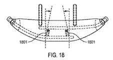
気体運搬ノズル・パターンに加えて、左側および右側のノズルまたはノズル・パターンによって形成される気体流路の軸の間の挟まれた角度は非平行であってよい。例えば、図18に示されるように、ノズル気体流路1801および出口軸は内側に角度付けされてよく、例えば内側に約0.5〜20度の角度、好適には内側に約2〜6度の角度で角度付けされてよい。この角度により、鼻孔気道に入る換気気体流を鼻孔気道に位置合わせすることができ、それにより流れ特性を最適化することができ、乱流および抵抗が最小である層流の陽圧の流れの形成を促進することができる。
In addition to the gas carrying nozzle pattern, the sandwiched angle between the left and right nozzles or the axis of the gas flow path formed by the nozzle pattern may be non-parallel. For example, as shown in FIG. 18, the nozzle
図14および図15は鼻に入る気体流路パターンを説明している。この記述では、例として、左側および右側の二重の気体運搬ノズル・パターンが使用される。示されるように、二重のノズル構成により鼻孔気道内に形成される組合せの気体流パターンが鼻孔気道経路の固有の断面全体にわたって運搬される流れおよび速度プロファイルを一様に分布させることができる。これにより、気体が鼻気道内に深く入る前で陽圧が形成されるのを改善することができ、層流が改善され、ユーザを刺激する可能性がある乱流を減少させることができる。例えば、流れプロファイルがより集中している場合、高速の流れが鼻道の内側の神経受容体に衝突する可能性があり、ユーザがそれを許容できない場合がある。試験では、より集中した流れプロファイルがユーザを刺激し、より分散した流れプロファイルが許容され得ることが分かった。ノズルによって形成される流れパターンがユーザの鼻の生体構造のサイズおよび形状に適合するように、ノズルの間隔、角度、回転位置および/または方向は調節可能であってよく、または、マスクが多様なサイズで利用可能であってよい。例えば、二重のノズルが使用される場合、ノズルの位置は、一対のノズルによって形成される長円形パターンの回転位置を回転させるように、回転され得、それにより、長円形パターンがユーザの鼻孔気道の長円形方向に適合するようになる。 14 and 15 illustrate the gas flow path pattern entering the nose. In this description, the left and right dual gas carrying nozzle patterns are used as an example. As shown, the dual nozzle configuration allows the combined gas flow pattern formed in the nostril airway to evenly distribute the flow and velocity profile carried across the unique cross section of the nostril airway path. This can improve the formation of positive pressure before gas enters deeply into the nasal airway, improving laminar flow and reducing turbulence that can irritate the user. For example, if the flow profile is more concentrated, the high velocity flow may impinge on the neural receptors inside the nasal passage and the user may not tolerate it. In testing, it was found that a more concentrated flow profile stimulates the user and a more distributed flow profile can be tolerated. The spacing, angle, rotational position and / or orientation of the nozzles may be adjustable or the masks may be varied so that the flow pattern formed by the nozzles matches the size and shape of the user's nasal anatomy. May be available in sizes. For example, if dual nozzles are used, the position of the nozzles can be rotated to rotate the rotational position of the oval pattern formed by the pair of nozzles so that the oval pattern is in the user's nostril Fits in the oval direction of the airway.
(噴射ポンプ咽喉を備える鼻マスク)
さらに、図19および図20に示されるように、マスクは噴射ポンプ咽喉区間1901を有してよい。図19は、マニホールド1907の底部で開いている取込みポート1905を有する。図20は同じ咽喉区間1901を示しているが、咽喉区間1901の基部のところで、マニホールドの頂部上にある取込みポート1905を有する。図19では、周囲空気はマニホールド1907の底部を通して取り込まれ得る。図20では、周囲空気はマニホールド1907の頂部を通過して取り込まれ得る。
(Nasal mask with jet pump throat)
Further, as shown in FIGS. 19 and 20, the mask may have a jet
噴射ポンプ咽喉区間1901は、性能に対する患者の生体構造の影響を最小にすることにより個人ごとの換気システムの性能を一定にするのに有用となり得る。噴射ポンプ咽喉区間1901はまた、気体運搬ノズル1903から出る高速気体および取り込まれる周囲空気が発する音を減衰するのに有用となり得る。噴射ポンプ咽喉区間1901は、別法として、図20に示されるように、噴射ポンプ咽喉区間1901の基部のところに取込みポート1905を有してよく、または、マニホールド1907が、図19に示されるように取込みアパーチャとして機能する貫通孔1909を有してよく、この貫通孔1909はマニホールド1907の底部からマニホールド1907の頂部までマニホールド1907の厚さを通って延在し、気体運搬ノズル1903に連通される。図19に示されるマスクの咽喉区間1901はまた、ベンチュリが発する音を減少させるのにも使用され得、したがってこの実施形態は、音を最小にすることが重要な性能要件であるような睡眠時無呼吸の用途で有用となり得る。図19では取込みポート1905はマニホールド1907の底部に示されているが、例えば、ノズル1903の近くの、噴射ポンプ咽喉区間1901の側面上にあってもよい。気体運搬管腔1911はマニホールド1907のいずれの近位端に含まれてもよい。
The jet
図19のノズルは任意のタイプのノズルであってよい。図19では、鼻の外側に、マニホールドの一部としての咽喉のオプションが存在してよい。 The nozzle of FIG. 19 may be any type of nozzle. In FIG. 19, there may be a throat option as part of the manifold outside the nose.
(その他のマスク形態ファクタ)
図21は代替の実施形態の鼻マスク2101を説明しており、ここでは、鼻の前部分に配置されて鼻の前部分に固定されるように構成される鼻部位2109から下方向に延在する垂直延長アーム2107に取り付けられた水平延長アーム2105を使用することにより、気体運搬ノズル2103が鼻の下に適切な位置に配置される。鼻部位2109は多様な手段により鼻に固定されてよく、鼻部位2109を顔に固定するために、鼻マスク2101に接続される気体運搬チューブ2115および圧力感知チューブ2111などが使用されてよい。鼻部位2109はまた、ストラップ、接着剤、摩擦係合、またはこれらの組合せなどの、別の手段により鼻に固定されてもよい。
(Other mask form factors)
FIG. 21 illustrates an alternative embodiment
垂直延長アーム2107は、気体運搬ノズル2103をユーザから適切な距離のところに配置するために調節可能であってよく、水平延長アーム2105は、鼻孔気道に正確に位置合わせされるように気体運搬ノズル2103を角度付けするために、回転式に調節可能であってよい。気体運搬ノズル2103の間の間隔は、例えば水平アームを直線的に調節することにより、調節可能であってよい。
The
呼吸圧力感知ポート(図示せず)が鼻部位2109から上方向に延在してよく、鼻の入口のところ、鼻の入口の近く、または鼻の入口の内側に確実に配置される。鼻部位2109はその底端部にシェルフ2113を有してよく、このシェルフ2113は鼻孔の縁の外側に面して位置決めされるのに使用される。呼吸圧力感知チューブ2111は、鼻部位2109の一方の側に取り付けられてよく、図21ではユーザの右側に取り付けられており、また、気体運搬チューブ2115が反対側に取り付けられてよい。
A respiratory pressure sensing port (not shown) may extend upward from the
鼻マスク2101はまた、CO2ガス抽出ポート(図示せず)、および、カプノメーター(図示せず)まで延在する導管などの、追加の感知機能を有することができ、これらは、二次チャネルを気体運搬管または圧力感知管に組み込みさらに必要不可欠なチャネルをマスクの鼻部位および/または延長アームに組み込むことにより、存在し得る。鼻部位2109はまた、鼻マスク2101がユーザに適切に装着されていない場合に気体運搬ノズル2103から運搬される気体が目の方に誘導されるのを防止することができる。
The
鼻マスク2101はまた、CO2ガス抽出ポート(図示せず)、および、カプノメーター(図示せず)まで延在する導管などの、追加の感知機能を有することができる。鼻部位2109はまた、鼻マスク2101がユーザに適切に装着されていない場合に気体運搬ノズル2103から運搬される気体が目の方に誘導されるのを防止することができる。
The
本発明のこの実施形態は、患者に対してこの治療を位置合わせするために鼻梁の中心の角度を使用することができる。試験において、換気気体の噴射を鼻孔(naris)に位置合わせするために気体運搬ノズル2103が鼻梁と平行となるように方向を定められる場合に最適な性能が達成されることが分かった。鼻部位2109を鼻梁の上に配置することにより気体運搬ノズル2103を鼻梁と平行とすることができるように、鼻マスク2101の気体運搬ノズル2103は鼻部位2109と平行となるように方向を定められてよい。
This embodiment of the invention can use the angle of the center of the nasal bridge to align this treatment with the patient. In testing, it has been found that optimal performance is achieved when the
なんらかの位置合わせ不良が生じた場合、性能が劣化する可能性がある。気体運搬ノズル2103は、好適には、鼻開口および鼻孔(naris)の軸に適切に位置合わせされた角度から10度以内に維持される。したがって、患者が鼻を左または右に移動させると(例えば、顎を過度に移動させることにより)、鼻マスク2101は鼻と共に移動することができることから、気体運搬ノズル2103は鼻の中心線に位置合わせされた状態で維持され、したがって鼻孔に位置合わせされた状態で維持される。図22では、気体運搬パターン2205は、効果的な長円形パターンを形成するために2つの交差する円形を有することができ、これらは例えば、上で説明したように鼻孔気道内に層状の断面の流れおよび陽圧を発生させることを目的として、二重のノズルによって作られる。
If any misalignment occurs, performance may be degraded. The
図22は鼻2201の底面図を示しており、図21の鼻マスク2101がいかにして鼻2201に位置合わせされるかを示している。呼吸圧力感知箇所2203および気体運搬パターン2205は、2つの大きな長円形によって示されているように、鼻2201および鼻孔気道2207の底面図の絵では重なっている。気体運搬パターン2205および鼻空気圧感知箇所2203がそれぞれ大きい円形および小さい円形によって示されている。この実施例ではパターン2205は左側および右側の鼻孔用の2つの気体運搬ノズルによって作られ、これは、図22のマスクに加えて、本発明の別のマスクの実施形態にも適用される。
FIG. 22 shows a bottom view of the
鼻空気圧感知ポートは、鼻孔(naris)内の呼吸経路内に感知ポートの明確な位置を得るのを補助するために突出していてよい。気体運搬ポートは、気体運搬経路が鼻孔気道への明確な経路を有するように、位置決めされ得る。感知ポートおよび気体運搬領域が鼻気道経路に適切に位置合わせされるように、2つ以上のサイズの鼻マスク2201が存在してよくおよび/またはマスク内に調節フィーチャが存在してよい。上の図は、感知箇所が鼻孔入口の近位側において、その入口の内側または同一面上に存在しなければならないか、または、外側にある場合にはその入口の5mm以内のわずかに外側に存在しなければならないことを説明しており、一方で気体運搬ノズルの先端部が鼻孔の入口から一定の距離、例えば10〜25mm離れて配置されることを説明している。この構成により、鼻マスク2201が感知精度を犠牲にすることなく噴射ポンプの幾何形状を利用することが可能となり、それにより換気装置が患者に適切に同期するようになる。また、気体流プロファイルは患者の鼻孔に入る前により規則的になることができ、患者にとって極めて不快で許容できないような乱流噴射が鼻孔に入ることはない。
The nasal air pressure sensing port may protrude to assist in obtaining a well-defined position of the sensing port in the respiratory path within the naris. The gas delivery port can be positioned so that the gas delivery path has a clear path to the nares airway. More than one size of
図23は図21に示される鼻マスク2201の患者回路アセンブリ2301の等角図を示している。呼吸圧力感知チューブ2111と気体運搬チューブ2115とを接合させるYコネクタ2303が示されており、患者回路の近位端のところで組み合わされた管2305および換気装置コネクタ2307が示されている。
FIG. 23 shows an isometric view of the
図24および図25は、図21に示される、見た目のために流線形のバージョンである鼻マスクを説明している。鼻部位2401、2501のフィーチャは、快適性を最適化するためにさらにはユーザにとっての目立ち度を最小にするために余分な箇所が取り除かれていてよい。図24では、気体運搬ノズル2403は、図21のマスクの垂直延長アームに対する鼻部位2401自体の延長部2405により、鼻の下に配置され得る。図25では、鼻部位2501は鼻梁の頂部の上にあるストリップであってよく、気体運搬ノズル2503は流線形の垂直アーム2505および流線形の水平アーム2507を使用することによって位置決めされ得る。
24 and 25 illustrate the nasal mask shown in FIG. 21, which is a streamlined version for appearance. The features of the
図26は図21に示されるマスクの1バージョンを示しており、ここでは、気体運搬ノズル2601が、延長アーム2605を備えるヘッドギア2603を使用して、鼻の下の適切な位置に配置されている。ヘッドギア2603および延長アーム2605は、気体運搬ノズル2601および呼吸圧力感知ポート(図示せず)を適切な位置に配置するために、調節可能であってよい。
FIG. 26 shows one version of the mask shown in FIG. 21, where a
以下の表は単に例示の値を列記しており、本開示を限定するものとして解釈されない。 The following table lists exemplary values only and is not to be construed as limiting the present disclosure.

図27は、本発明の作動機構を説明しており、さらに、本発明が肺疾患または神経筋疾患の用途に使用される場合に、本発明により患者の呼吸の動作がいかにして有利に影響を受けるかを説明している。患者の肺容量は、肺圧力の関数としてグラフ化することができ、曲線の内側の領域は動作を示し、通常はジュール毎リットル(J/L)で示され、通常の健康な成人では0.3〜0.6J/Lであってよい。呼吸障害がある患者では、例えば、COPDの場合に静的および動的過膨張を克服したりまたは繊維症またはARDSの場合に高い気道抵抗を克服したりするといったように、組織の疫病状態を克服するために、休息中さらには激しい運動中に呼吸するために4〜10倍の作業が必要である可能性がある。 FIG. 27 illustrates the operating mechanism of the present invention and how the patient's breathing behavior is advantageously affected by the present invention when the present invention is used for pulmonary or neuromuscular disease applications. Explaining what to receive. The patient's lung volume can be graphed as a function of lung pressure, with the area inside the curve showing movement, usually expressed in joules per liter (J / L), and 0. 0 for normal healthy adults. It may be 3 to 0.6 J / L. In patients with respiratory impairment, for example, overcoming tissue epidemic conditions such as overcoming static and dynamic hyperinflation in the case of COPD or high airway resistance in the case of fibrosis or ARDS To do so, it may require 4 to 10 times more work to breathe during rest and during intense exercise.
示されるグラフでは、圧力軸の下にある曲線の内側の領域は吸気WOBであり、圧力軸の上にある曲線の内側によって画定される領域は呼気WOBである。矢印は、RVからVTに始まり、その後VTからRVに戻る、時間経過での1回の呼吸の経過を示している。RV1およびVT1は、治療なしでの残留量および1回換気量である。線3201は非侵襲性開放鼻換気なしでの自発呼吸を示している。線3203は非侵襲性開放鼻換気を用いた自発呼吸を示しており、吸気の増大および終末呼気陽圧(positive end−expiratory pressure(PEEP))治療が用いられている。RV2およびVT2は治療を行った場合の残留量および1回換気量である。示されるように、この例では、残留量を増加させることができる呼吸流が治療の一部として与えられることから、治療によりRVが増加する。重要なことは、治療によりVTが増加し、RVの増加よりもより大幅に増加することであり、これは、治療の効果としてより多くの量が肺に入ったり肺から出たりすることを示している。1回換気量の増加は、臨床的に有効であると考えられるが、開放換気式で非侵襲性の最小限に目立たないシステムで実現するのは技術的に難しい。グラフに示されるように、本発明を作動させた場合の患者の吸気WOBは、本発明を停止させた場合の患者の吸気WOBより約25%少ない可能性がある。また、吸気肺圧力が増加し(上昇する)、1回換気量が増加し、呼気中に治療が行われる場合には任意選択で呼気圧力が増加する。示される例では、換気装置が呼気段階中に気体を提供しているので、残留量が増加する一方で、残留量に影響を与えないように換気パラメータが滴定され得、また、治療の受けているときの肺筋を働かせる患者の能力により、患者の肺機能はCOPDの場合にはリモデルされ得、それにより実際に残留量の減少をより通常の値にすることができる。示されるグラフでは、治療の波形は、換気装置吸気段階治療出力(ventilator inspiratory phase therapy output)に対する早期吸気トリガ時間を想定しており、さらに、容量出力が患者の吸気時間内に運ばれることを想定している。しかし、任意選択で、異なる運搬波形および運搬同期が実行され得、それによりWOB曲線が調節され得る。例えば、換気装置吸気段階治療は、吸気の終了時に運搬を終了させて人の呼吸サイクルの後で実施され得、方形または上昇波形プロファイルで実施され得る。この場合、肺圧力ゼロ軸の上方の点において吸気が終了して呼気に移行するように、治療のWOB曲線は曲線の右側上向きに傾斜する。
In the graph shown, the area inside the curve below the pressure axis is the inspiration WOB and the area defined by the inside of the curve above the pressure axis is the exhalation WOB. The arrows indicate the course of one breath over time starting from RV to VT and then back from VT to RV. RV1 and VT1 are residual volume and tidal volume without treatment.
図28は、従来の換気と比較して、肺シミュレータ・ベンチ・モデル上でNIOVにより達成される肺容量をグラフで示している。すべての波形で、シミュレーションした患者は245mlの1回換気量が得られるように同じ呼気努力で自発呼吸をし、この臨床的目標は、患者の1回換気量を245ml(3301)から380ml(3303)まで増加させることである。グラフの左から右への第1の波形では、患者の呼吸3305は補助を受けてなく、したがって患者は245mlの1回換気量を受ける。次の波形では、同じ努力でシミュレーションした患者が、密封呼吸マスクまたはカフ付き気道チューブなどの従来のクローズ型システム換気装置の補助を受ける。換気装置出力3309は380mlの所望される「補助」1回換気量を実現するレベルに設定される。換気装置により肺に運搬される気体と、換気装置によって運搬されるが肺には到達せずに周囲に廃棄される気体3307との間に差異があることから、換気装置はこの目標を達成するために420mlに設定される。第3の波形では、換気装置が患者から引き離されている場合に行われるように、従来の換気装置システムにわずかな漏洩が導入される。380mlの所望の「補助」1回換気量を達成するために、次に換気装置は705mlに設定されなければならない。第2および第3の波形ではさらに、患者の肺が受ける容量がすべて、これらの従来のシステム内に存在しなければならない換気装置から発生することが分かる。第4の波形では、患者はNIOVで補助されており、示されるように、NIOV換気装置出力は、380mlの所望の「補助」レベルを達成するのに、90mlに設定されるだけでよい。この場合、380mlの1回換気量の一部のみが換気装置から来て、380mlの大部分は取込みおよび自発吸気された周囲空気3311から来ることから、NIOVシステムは、他のシステムよりはるかに、より効率的であり、より快適であり、より健康的である。
FIG. 28 graphically illustrates lung volume achieved by NIOV on a lung simulator bench model compared to conventional ventilation. For all waveforms, the simulated patient spontaneously breathed with the same expiratory effort to obtain 245 ml tidal volume, and this clinical goal is to change the patient's tidal volume from 245 ml (3301) to 380 ml (3303). ). In the first waveform from left to right of the graph, the patient's
図29は、肺シミュレータ・ベンチ・モデルを使用して、酸素治療と比較したNIOVをグラフで示している。左側の第1の波形では、患者は補助を受けておらず、−0.8cmH2O(78Pa)の努力で呼吸して、248mlの吸気される1回換気量3401を生み出す。第2の波形および第3の波形では、患者は、鼻カニューレを介して酸素の連続流3403およびパルス流3405をそれぞれ受け、ここでは肺圧力および1回換気量への影響は存在しないか無視できる程度である。第4の波形では、NIOV3407が使用されており、肺圧力および1回換気量における際立った増加を示しており、したがって、NIOVが開放気道システムであるにも関わらず、上で説明したようにNIOVが呼吸の動作を補助することが示されている。
FIG. 29 graphically illustrates NIOV compared to oxygen therapy using a lung simulator bench model. In the first waveform on the left, the patient is not assisted and breathes with an effort of -0.8 cm H2O (78 Pa) to produce 248 ml of inspiratory tidal volume 3401. In the second and third waveforms, the patient receives a continuous flow of
図30A乃至図30Lは、本発明の例示の換気気体運搬プロファイルならびにそれらのそれぞれの肺容量および肺圧力への影響を示している。 FIGS. 30A-30L illustrate exemplary ventilation gas delivery profiles of the present invention and their effect on lung volume and lung pressure, respectively.
図30A、図30D、図30Gおよび図30Jは、換気装置によって得られる例示の圧力および/または流れの波形を示している。図30Aは、完全な吸気サイクルで得られる方形波形3501を説明している。図30Dは上昇・下降波形3503を説明している。図30Gは、患者の自発吸気の時間の第1の部分において得られる方形波形3507を説明している。図30Jは、吸気段階で得られる第1の振幅3511と呼気段階で得られる第2の振幅3513とを有する多レベル振幅波形3509を示しており、ここでは、第2の振幅3513は例えば終末呼気陽圧(PEEP)を提供するのに使用され、これは一部の臨床用途において有効である。本発明には、下降するまたは上昇する台形の方形波などの別の波形が含まれてもよい。換気装置から気体運搬管への圧力および流量出力は通常5〜40psi(34〜275kPa)および6〜30lpmの範囲内にある。
30A, 30D, 30G, and 30J illustrate exemplary pressure and / or flow waveforms obtained by the ventilator. FIG. 30A illustrates a
図30B、図30E、図30Hおよび図30Kは、換気装置出力3515および取込み量3517を含む治療によって得られる肺容量を説明している。
FIGS. 30B, 30E, 30H, and 30K illustrate the lung volume that can be obtained by treatment including
図30C、図30F、図30Iおよび図30Lは、破線3519で示される治療なしの肺圧力と、実線3521で示される治療により得られる肺圧力とを示しており、図30Cでは吸気段階全体の吸気陽圧が示されており、図30Fおよび30Iでは吸気段階の一部分での吸気陽圧が示されており、ここでは治療が呼気3523まで拡張されており、また、図30Lでは上昇した陰圧の吸気圧力が示されている。
30C, FIG. 30F, FIG. 30I, and FIG. 30L show the lung pressure without treatment indicated by the dashed
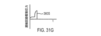
図36A乃至図36Lは、本発明の追加の例示的な換気気体運搬プロファイルならびにそれらのそれぞれの肺容量および肺圧力への影響を説明している。 Figures 36A-36L illustrate additional exemplary ventilation gas delivery profiles of the present invention and their impact on their respective lung volumes and pressures.
図31Aは上昇波形3601を説明している。図31Dは下降波形3603を説明している。図31Gは、例えば、呼吸段階の初期段階で必要な酸素分子を肺へと運搬するための、吸気段階の第1の部分における低振幅と、例えば呼吸の動作を補助するために治療の機械的補助部分を実現するための、吸気段階の第2の部分における高振幅と、を有する多レベル波形3605を説明している。図31Jは、ほぼ同じベンチュリ、取込み量、および治療効果を有する一方で、気体供給装置をより効率的に使用することができる振動波形3607を説明している。
FIG. 31A illustrates the rising
図31B、図31E、図31Hおよび31Kは、換気装置出力3609および取込み量3611を含む治療によって得られる肺容量を説明している。
FIGS. 31B, 31E, 31H and 31K illustrate the lung volume obtained by treatment including
図31C、図31F、図31Iおよび図31Lは、破線3613によって示される治療なしの肺圧力と、実線3615によって示される治療により得られる肺圧力とを示している。
31C, FIG. 31F, FIG. 31I and FIG. 31L show the lung pressure without treatment indicated by the dashed
この治療により得られる肺圧力は以下の要因の組合せによって制御され得る。気体運搬回路圧力、噴射ポンプのデザインおよび構成、患者の肺コンプライアンスおよび気道耐性、患者の呼吸努力、患者の吸気段階に対する換気装置出力のタイミング、ならびに、換気装置出力波形。しかし、通常、患者の吸気段階の開始時に始まる500ミリ秒で得られる、100mlを運搬する方形波形の30psi(207kPa)の気体運搬回路圧力が、肺圧力を5〜15cmH2O(490〜1471Pa)だけ増加させることができる。また、通常、患者の吸気段階の大部分の700ミリ秒の間に得られる、250mlを運搬する台形波形の30psi(207kPa)の気体運搬回路圧力が、肺圧力を10〜25cmH2O(981〜2452Pa)だけ増加させることができる。換気装置によって運搬される気体は、酸素、空気、酸素と空気との混合気、または、ヘリウムなどの治療気体であってよい。本発明の主要な作動機構では、患者の肺圧力および肺容量が増加し、それにより患者が疲労および呼吸困難により制限を受けることなく、自力で呼吸することが可能となる。本発明の別の作動機構では、この治療によって提供される圧力補助および量的補助を受けて、患者は呼吸努力を軽減することができ、したがって、治療による合計の肺容量は変化しないが、呼吸動作は軽減される。本発明の別の主要な実施形態では、上記の2つの作動機構の組合せが行われてよい。
The lung pressure obtained with this treatment can be controlled by a combination of the following factors: Gas delivery circuit pressure, injection pump design and configuration, patient lung compliance and airway tolerance, patient breathing effort, timing of ventilator output relative to patient inspiratory phase, and ventilator output waveform. However, a 30 psi (207 kPa) square wave gas delivery circuit pressure carrying 100 ml, typically obtained at the beginning of the patient's inspiratory phase, increases the lung pressure by 5-15 cm H2O (490-1471 Pa). Can be made. Also, a
図32は、一実施形態によるタイミングおよび気体流運搬の図である。気体流運搬率3701の振幅は気道圧力3703に影響するように呼吸数によって調整される。呼吸数が増加すると、振幅が増大する。容量運搬は、静止状態と動作状態との間で、ユーザによって変更されない限り一定の率で維持され得る。しかし、動作状態では、より高い流量率によりより多くの気体が取り込まれることから、システムによって得られる出力量はより大きくてよく、それにより、吸気段階でより大きい出力および肺圧力が得られる。また、運搬される流れの運搬の時間は、呼吸期間の割合として、ユーザによって調節され得る。例えば、呼吸期間が3秒である場合、運搬時間設定値の25%が、得られる0.75秒の流れパルスに等しくなる。得られる流れパルス幅は呼吸数により変化するが、このパルス幅は呼吸期間の25%であり続ける(ユーザによって変更されない限り)。この設定値は、例えば、呼吸期間の15%から70%の範囲内で設定されてよい。この設定値は容量の設定値とは無関係であってよい。例えば、25%対40%の設定値は同じ設定量を運搬することができ、異なる流量率でもその設定量を運搬しているにすぎない場合がある。得られる流れパルス時間を調節するためのアルゴリズムは、例えば、その時点の呼吸期間を測定するのに直前の3回から5回の呼吸を調べることができ、また、異常値の呼吸を排除するための修正係数を有してよい。
FIG. 32 is a diagram of timing and gas flow delivery according to one embodiment. The amplitude of the
上述の説明は本発明の好適な実施形態を対象としているが、別の変形形態および修正形態が当業者には明白であり、本発明の精神および範囲から逸脱することなく作られ得ることに留意されたい。さらに、本発明の一実施形態に関連させて説明した特徴は、上で明確に述べられていなくても、別の実施形態と併せて使用され得る。 While the above description is directed to preferred embodiments of the invention, it is noted that other variations and modifications will be apparent to those skilled in the art and may be made without departing from the spirit and scope of the invention. I want to be. Furthermore, features described in connection with one embodiment of the invention may be used in conjunction with another embodiment, even if not explicitly stated above.
Claims (23)
気体供給源と;
気体運搬回路と;
非密封式の鼻インターフェイスを通って流れない周囲空気を患者が鼻道内に直接吸ったり吐き出したりすることを可能にしながら患者の鼻に連通されるように構成される、前記非密封式の鼻インターフェイスと;
前記気体運搬回路および前記気体供給源に接続可能であり、鼻から一定の距離のところにある、前記非密封式の鼻インターフェイスに付随し自由空間にあるノズルとを有し、
前記ノズルは、前記ノズルの近くに陰圧領域を形成して鼻の入口の近くに陽圧領域を形成することにより鼻道内に気体を運搬することができ、
前記気体供給源からの気体と前記ノズルから出る気体から取り込まれる空気との組合せが換気補助を行う、ことを特徴とするシステム。 A system for providing ventilation assistance,
A gas source;
A gas carrying circuit;
Configured ambient air does not flow through the non-sealing of the nasal interface so that the patient communicates with the patient's nose while allowing or discharging inhaling directly into the nasal tract, nasal interface of the unsealed When;
Said gas Ri conveying circuit and connectable der to said gas source, located at the nose of the fixed distance, and a nozzle in the in unsealed concomitant free space nasal interface,
The nozzle can carry gas into the nasal passage by creating a negative pressure area near the nozzle and a positive pressure area near the nasal entrance,
A combination of gas from the gas supply and air taken from the gas exiting the nozzle provides ventilation assistance.
鼻孔の縁のへりのところで前記縁の遠位側に形成され、
鼻孔気道内の位置でその位置の遠位側に形成される、請求項1に記載のシステム。 The positive pressure region is formed at one location outside the nose and distal to that location;
Formed at the edge of the nostril edge distal to the edge;
The system of claim 1, wherein the system is formed at a location within the nostril airway and distal to that location.
前記マニホールドは、鼻孔入口から一定距離離れたところに前記ノズルを配置するように構成され、また、鼻孔気道の中心線に対して角度を付けて前記ノズルを配置するように構成される、請求項1に記載のシステム。 The non-sealed nasal interface has a manifold, the manifold has the nozzle;
The manifold is configured to position the nozzle at a distance from a nostril inlet and is configured to position the nozzle at an angle with respect to a nostril airway centerline. The system according to 1.
前記1つまたは複数のセンサは、前記ノズルから鼻に向かって延在して前記陽圧領域内で終端する少なくとも1つの感知チャネルを有し、
前記ノズルから離れるように遠位側に延在する感知チャネルを有し、
前記感知チャネルは鼻の中まで延在し、
鼻孔入口から+/−約5mmの範囲まで延在する、請求項1に記載のシステム。 Further comprising one or more sensors;
The one or more sensors have at least one sensing channel extending from the nozzle toward the nose and terminating in the positive pressure region;
Having a sensing channel extending distally away from the nozzle;
The sensing channel extends into the nose;
The system of claim 1, extending from the nostril entrance to a range of +/− about 5 mm.
円形パターンまたは長円形パターンに配置される複数の気体運搬ノズルのアレイを有する、請求項1に記載のシステム。 The nozzle is one of an oval gas carrying nozzle orifice,
The system of claim 1, comprising an array of a plurality of gas carrying nozzles arranged in a circular or oval pattern.
前記噴射ポンプ咽喉はマニホールドに連結され、前記ノズルは前記噴射ポンプ咽喉を通る噴射ポンプ咽喉流れ経路に連結され
前記マニホールドは前記噴射ポンプ咽喉流れ経路に連通される取込みポートを有する、請求項1に記載のシステム。 Further having a jet throat including a flow path;
The injection pump throat is connected to a manifold, the nozzle is connected to an injection pump throat flow path through the injection pump throat, and the manifold has an intake port in communication with the injection pump throat flow path. System.
前記コネクタは、鼻孔の縁のへりを基準に前記非密封式の鼻インターフェイスを位置決めするための突起を有し、
前記コネクタは、鼻孔気道の中心線に位置合わせするように前記ノズルの角度を調節する、請求項1に記載のシステム。 The unsealed nasal interface has a connector for coupling the system to the nasal bridge and for aligning the at least one gas carrying spray nozzle to the nasal inlet;
The connector has a protrusion for positioning the non-sealing nasal interface relative to the edge of the nostril edge;
The system of claim 1, wherein the connector adjusts the angle of the nozzle to align with a nostril airway centerline.
Applications Claiming Priority (27)
| Application Number | Priority Date | Filing Date | Title |
|---|---|---|---|
| US23972809P | 2009-09-03 | 2009-09-03 | |
| US61/239,728 | 2009-09-03 | ||
| US25576009P | 2009-10-28 | 2009-10-28 | |
| US61/255,760 | 2009-10-28 | ||
| US29436310P | 2010-01-12 | 2010-01-12 | |
| US61/294,363 | 2010-01-12 | ||
| US30637010P | 2010-02-19 | 2010-02-19 | |
| US61/306,370 | 2010-02-19 | ||
| USPCT/US2010/029874 | 2010-04-02 | ||
| PCT/US2010/029871 WO2010115166A1 (en) | 2009-04-02 | 2010-04-02 | Methods, systems and devices for non-invasive open ventilation with gas delivery nozzles in free space |
| US12/753,846 US9675774B2 (en) | 2009-04-02 | 2010-04-02 | Methods, systems and devices for non-invasive open ventilation with gas delivery nozzles in free space |
| US12/753,854 US10046133B2 (en) | 2009-04-02 | 2010-04-02 | Methods, systems and devices for non-invasive open ventilation for providing ventilation support |
| US12/753,853 | 2010-04-02 | ||
| US12/753,854 | 2010-04-02 | ||
| USPCT/US2010/029875 | 2010-04-02 | ||
| USPCT/US2010/029873 | 2010-04-02 | ||
| US12/753,853 US10695519B2 (en) | 2009-04-02 | 2010-04-02 | Methods, systems and devices for non-invasive open ventilation with gas delivery nozzles within nasal pillows |
| PCT/US2010/029875 WO2010115170A2 (en) | 2009-04-02 | 2010-04-02 | Methods, systems and devices for non-invasive open ventilation for treating airway obstructions |
| USPCT/US2010/029871 | 2010-04-02 | ||
| PCT/US2010/029873 WO2010115168A1 (en) | 2009-04-02 | 2010-04-02 | Methods, systems and devices for non-invasive open ventilation with gas delivery nozzles within an outer tube |
| US12/753,851 | 2010-04-02 | ||
| PCT/US2010/029874 WO2010115169A1 (en) | 2009-04-02 | 2010-04-02 | Methods, systems and devices for non-invasive open ventilation for providing ventilation support |
| US12/753,851 US9180270B2 (en) | 2009-04-02 | 2010-04-02 | Methods, systems and devices for non-invasive open ventilation with gas delivery nozzles within an outer tube |
| US12/753,856 | 2010-04-02 | ||
| US12/753,856 US9227034B2 (en) | 2009-04-02 | 2010-04-02 | Methods, systems and devices for non-invasive open ventilation for treating airway obstructions |
| US12/753,846 | 2010-04-02 | ||
| PCT/US2010/047920 WO2011029073A1 (en) | 2009-09-03 | 2010-09-03 | Methods, systems and devices for non-invasive ventilation including a non-sealing ventilation interface with a free space nozzle feature |
Publications (3)
| Publication Number | Publication Date |
|---|---|
| JP2013503719A JP2013503719A (en) | 2013-02-04 |
| JP2013503719A5 JP2013503719A5 (en) | 2013-10-24 |
| JP5758898B2 true JP5758898B2 (en) | 2015-08-05 |
Family
ID=70049795
Family Applications (2)
| Application Number | Title | Priority Date | Filing Date |
|---|---|---|---|
| JP2012528112A Active JP6153725B2 (en) | 2009-09-03 | 2010-09-03 | Ventilation assistance system and ventilator including an unsealed ventilation interface with intake ports and / or pressure features |
| JP2012528111A Active JP5758898B2 (en) | 2009-09-03 | 2010-09-03 | Ventilation assist system and ventilator including an unsealed ventilation interface with free space nozzle features |
Family Applications Before (1)
| Application Number | Title | Priority Date | Filing Date |
|---|---|---|---|
| JP2012528112A Active JP6153725B2 (en) | 2009-09-03 | 2010-09-03 | Ventilation assistance system and ventilator including an unsealed ventilation interface with intake ports and / or pressure features |
Country Status (4)
| Country | Link |
|---|---|
| EP (1) | EP2473220B1 (en) |
| JP (2) | JP6153725B2 (en) |
| CA (1) | CA2773048C (en) |
| WO (1) | WO2011029073A1 (en) |
Families Citing this family (28)
| Publication number | Priority date | Publication date | Assignee | Title |
|---|---|---|---|---|
| US7588033B2 (en) | 2003-06-18 | 2009-09-15 | Breathe Technologies, Inc. | Methods, systems and devices for improving ventilation in a lung area |
| EP1660004A4 (en) | 2003-08-18 | 2017-05-31 | Breathe Technologies, Inc. | Method and device for non-invasive ventilation with nasal interface |
| CA2623756A1 (en) | 2005-09-20 | 2007-03-29 | Lutz Freitag | Systems, methods and apparatus for respiratory support of a patient |
| WO2007142812A2 (en) | 2006-05-18 | 2007-12-13 | Breathe Technologies, Inc. | Tracheotomy method and device |
| WO2008019102A2 (en) | 2006-08-03 | 2008-02-14 | Breathe Technologies, Inc. | Methods and devices for minimally invasive respiratory support |
| WO2008144589A1 (en) | 2007-05-18 | 2008-11-27 | Breathe Technologies, Inc. | Methods and devices for sensing respiration and providing ventilation therapy |
| JP5513392B2 (en) | 2007-09-26 | 2014-06-04 | ブリーズ・テクノロジーズ・インコーポレーテッド | Method and apparatus for treating sleep apnea |
| CA2700878C (en) | 2007-09-26 | 2018-07-24 | Breathe Technologies, Inc. | Methods and devices for providing inspiratory and expiratory flow relief during ventilation therapy |
| WO2009151791A2 (en) | 2008-04-18 | 2009-12-17 | Breathe Technologies, Inc. | Methods and devices for sensing respiration and controlling ventilator functions |
| US8770193B2 (en) | 2008-04-18 | 2014-07-08 | Breathe Technologies, Inc. | Methods and devices for sensing respiration and controlling ventilator functions |
| US8677999B2 (en) | 2008-08-22 | 2014-03-25 | Breathe Technologies, Inc. | Methods and devices for providing mechanical ventilation with an open airway interface |
| US10252020B2 (en) | 2008-10-01 | 2019-04-09 | Breathe Technologies, Inc. | Ventilator with biofeedback monitoring and control for improving patient activity and health |
| US9132250B2 (en) | 2009-09-03 | 2015-09-15 | Breathe Technologies, Inc. | Methods, systems and devices for non-invasive ventilation including a non-sealing ventilation interface with an entrainment port and/or pressure feature |
| CA2757588C (en) | 2009-04-02 | 2017-01-03 | Breathe Technologies, Inc. | Methods, systems and devices for non-invasive open ventilation with gas delivery nozzles in free space |
| US9962512B2 (en) | 2009-04-02 | 2018-05-08 | Breathe Technologies, Inc. | Methods, systems and devices for non-invasive ventilation including a non-sealing ventilation interface with a free space nozzle feature |
| CN102762250B (en) | 2009-09-03 | 2017-09-26 | 呼吸科技公司 | Mthods, systems and devices for including the invasive ventilation with entrainment port and/or the non-tight vented interface of pressure characteristic |
| AU2011292111B2 (en) | 2010-08-16 | 2015-03-26 | Breathe Technologies, Inc. | Methods, systems and devices using LOX to provide ventilatory support |
| WO2012045051A1 (en) | 2010-09-30 | 2012-04-05 | Breathe Technologies, Inc. | Methods, systems and devices for humidifying a respiratory tract |
| EP2670491B1 (en) * | 2011-01-31 | 2019-06-05 | Breathe Technologies, Inc. | System for ventilation using a nasal ventilation mask with a manifold and internal compliant tube and nasal sealing cushion assembly |
| WO2014042862A1 (en) | 2012-09-12 | 2014-03-20 | Silverbow Development Llc | Nasal interface apparatus and systems for use with a respiratory assist device |
| US11904096B2 (en) | 2012-09-12 | 2024-02-20 | Inogen, Inc. | Nasal interface apparatus and systems for use with a respiratory assist device |
| AU2014335018B2 (en) * | 2013-10-16 | 2019-06-13 | Fisher & Paykel Healthcare Limited | A patient interface |
| CN113144364A (en) | 2014-09-19 | 2021-07-23 | 费雪派克医疗保健有限公司 | Patient interface |
| GB201510384D0 (en) * | 2015-06-13 | 2015-07-29 | Young Peter J | Medical gas delivery system |
| WO2018071699A1 (en) * | 2016-10-13 | 2018-04-19 | Vyaire Medical Capital Llc | Nasal cannula systems |
| US10792449B2 (en) | 2017-10-03 | 2020-10-06 | Breathe Technologies, Inc. | Patient interface with integrated jet pump |
| DE102018112903A1 (en) | 2018-03-16 | 2019-09-19 | Fritz Stephan Gmbh Medizintechnik | Oxygen therapy unit |
| EP3914326A4 (en) * | 2019-01-24 | 2022-10-19 | Inogen, Inc. | Nasal interface apparatus and systems for use with a respiratory assist device |
Family Cites Families (16)
| Publication number | Priority date | Publication date | Assignee | Title |
|---|---|---|---|---|
| SE462614B (en) * | 1988-12-06 | 1990-07-30 | Conny Peder Gunnar Moa | DEVICE TO GENERATE CONTINUOUS POSITIVE AIR PRESSURE IN SPONTANEOUS THROUGH EJECTOR EFFECTS |
| US20050121033A1 (en) * | 1998-02-25 | 2005-06-09 | Ric Investments, Llc. | Respiratory monitoring during gas delivery |
| US6938619B1 (en) * | 2000-06-13 | 2005-09-06 | Scott Laboratories, Inc. | Mask free delivery of oxygen and ventilatory monitoring |
| US6851425B2 (en) * | 2001-05-25 | 2005-02-08 | Respironics, Inc. | Exhaust port assembly for a pressure support system |
| WO2003068301A1 (en) * | 2002-02-15 | 2003-08-21 | Oridion Medical 1987 Ltd. | Dual function nasal cannula |
| GB0204117D0 (en) * | 2002-02-21 | 2002-04-10 | E M E Electro Medical Equipmen | Breathing device |
| NZ626589A (en) * | 2003-02-21 | 2016-01-29 | Resmed Ltd | Nasal assembly |
| US20050011524A1 (en) * | 2003-07-17 | 2005-01-20 | Marguerite Thomlinson | Nasal interface apparatus |
| WO2005007056A2 (en) * | 2003-07-22 | 2005-01-27 | Zinder, Oren | A respiratory aid system and method |
| US8225796B2 (en) * | 2003-07-28 | 2012-07-24 | Salter Labs | Respiratory therapy system including a nasal cannula assembly |
| US8100125B2 (en) * | 2005-09-30 | 2012-01-24 | Carefusion 207, Inc. | Venturi geometry design for flow-generator patient circuit |
| US7578294B2 (en) * | 2005-12-02 | 2009-08-25 | Allegiance Corporation | Nasal continuous positive airway pressure device and system |
| JP2009519759A (en) * | 2005-12-14 | 2009-05-21 | マージェネット メディカル,インコーポレイテッド | High flow therapy device and related method utilizing non-hermetic respiratory interface |
| US20070163600A1 (en) * | 2006-01-11 | 2007-07-19 | Leslie Hoffman | User interface and head gear for a continuous positive airway pressure device |
| JP2007229207A (en) * | 2006-03-01 | 2007-09-13 | Saitama Univ | Nasal cpap element |
| US8210182B2 (en) * | 2007-12-28 | 2012-07-03 | Carefusion 207, Inc. | Continuous positive airway pressure device |
-
2010
- 2010-09-03 JP JP2012528112A patent/JP6153725B2/en active Active
- 2010-09-03 EP EP10814608.5A patent/EP2473220B1/en active Active
- 2010-09-03 JP JP2012528111A patent/JP5758898B2/en active Active
- 2010-09-03 WO PCT/US2010/047920 patent/WO2011029073A1/en active Application Filing
- 2010-09-03 CA CA2773048A patent/CA2773048C/en active Active
Also Published As
| Publication number | Publication date |
|---|---|
| WO2011029073A1 (en) | 2011-03-10 |
| CA2773048A1 (en) | 2011-03-10 |
| EP2473220A1 (en) | 2012-07-11 |
| EP2473220A4 (en) | 2014-10-01 |
| CA2773048C (en) | 2017-01-03 |
| JP6153725B2 (en) | 2017-06-28 |
| JP2013503720A (en) | 2013-02-04 |
| EP2473220B1 (en) | 2018-11-07 |
| JP2013503719A (en) | 2013-02-04 |
Similar Documents
| Publication | Publication Date | Title |
|---|---|---|
| JP5758898B2 (en) | Ventilation assist system and ventilator including an unsealed ventilation interface with free space nozzle features | |
| US20210353884A1 (en) | Methods, systems and devices for non-invasive ventilation including a non-sealing ventilation interface with an entrainment port and/or pressure feature | |
| US9962512B2 (en) | Methods, systems and devices for non-invasive ventilation including a non-sealing ventilation interface with a free space nozzle feature | |
| US10265486B2 (en) | Methods, systems and devices for non-invasive ventilation including a non-sealing ventilation interface with an entrainment port and/or pressure feature | |
| US11896766B2 (en) | Methods, systems and devices for non-invasive ventilation with gas delivery nozzles in free space | |
| US9199053B1 (en) | Methods, systems and devices for ventilation using a nasal ventilation mask with a manifold and internal compliant tube and nasal sealing cushion assembly | |
| CN102625720B (en) | For including the mthods, systems and devices with the invasive ventilation of non-tight vented interface of free space nozzle characteristics |
Legal Events
| Date | Code | Title | Description |
|---|---|---|---|
| A521 | Request for written amendment filed |
Free format text: JAPANESE INTERMEDIATE CODE: A523 Effective date: 20130903 |
|
| A621 | Written request for application examination |
Free format text: JAPANESE INTERMEDIATE CODE: A621 Effective date: 20130903 |
|
| A977 | Report on retrieval |
Free format text: JAPANESE INTERMEDIATE CODE: A971007 Effective date: 20140729 |
|
| A131 | Notification of reasons for refusal |
Free format text: JAPANESE INTERMEDIATE CODE: A131 Effective date: 20140805 |
|
| A521 | Request for written amendment filed |
Free format text: JAPANESE INTERMEDIATE CODE: A523 Effective date: 20141105 |
|
| TRDD | Decision of grant or rejection written | ||
| A01 | Written decision to grant a patent or to grant a registration (utility model) |
Free format text: JAPANESE INTERMEDIATE CODE: A01 Effective date: 20150507 |
|
| A61 | First payment of annual fees (during grant procedure) |
Free format text: JAPANESE INTERMEDIATE CODE: A61 Effective date: 20150604 |
|
| R150 | Certificate of patent or registration of utility model |
Ref document number: 5758898 Country of ref document: JP Free format text: JAPANESE INTERMEDIATE CODE: R150 |
|
| R250 | Receipt of annual fees |
Free format text: JAPANESE INTERMEDIATE CODE: R250 |
|
| R250 | Receipt of annual fees |
Free format text: JAPANESE INTERMEDIATE CODE: R250 |
|
| R250 | Receipt of annual fees |
Free format text: JAPANESE INTERMEDIATE CODE: R250 |
|
| R250 | Receipt of annual fees |
Free format text: JAPANESE INTERMEDIATE CODE: R250 |
|
| R250 | Receipt of annual fees |
Free format text: JAPANESE INTERMEDIATE CODE: R250 |
|
| R250 | Receipt of annual fees |
Free format text: JAPANESE INTERMEDIATE CODE: R250 |