JP5750697B2 - Display device and display program - Google Patents
Display device and display program Download PDFInfo
- Publication number
- JP5750697B2 JP5750697B2 JP2011102004A JP2011102004A JP5750697B2 JP 5750697 B2 JP5750697 B2 JP 5750697B2 JP 2011102004 A JP2011102004 A JP 2011102004A JP 2011102004 A JP2011102004 A JP 2011102004A JP 5750697 B2 JP5750697 B2 JP 5750697B2
- Authority
- JP
- Japan
- Prior art keywords
- unit
- image
- display
- display device
- imaging
- Prior art date
- Legal status (The legal status is an assumption and is not a legal conclusion. Google has not performed a legal analysis and makes no representation as to the accuracy of the status listed.)
- Expired - Fee Related
Links
Images


Landscapes
- Studio Devices (AREA)
- Indication In Cameras, And Counting Of Exposures (AREA)
- Camera Data Copying Or Recording (AREA)
- Television Signal Processing For Recording (AREA)
Description
本発明は、画像を表示可能な表示装置および表示プログラムに関する。 The present invention relates to a display device and a display program capable of displaying an image.
従来、撮影した画像に対し、測位によって取得した位置情報に対応する地名等を記憶するカメラが知られている。このようなカメラとして、GPS(Global Positioning System)の測位処理を撮像と並行して行いながら被写体の位置に対応する地名等の名称を抽出し、この抽出した名称を被写体に重ねて表示する技術が開示されている(例えば、特許文献1を参照)。この技術では、カメラがGPSの測位処理によってカメラ位置を取得するとともに、被写体の測距および方位計測を行い、これらの量をもとに被写体の位置を算出する。その後、カメラは、算出した被写体の位置を用いてデータベースを検索し、撮影時のズーム値に応じた名称を抽出して撮影画像とともに表示する。 2. Description of the Related Art Conventionally, a camera that stores a place name corresponding to position information acquired by positioning for a captured image is known. As such a camera, there is a technique for extracting a name such as a place name corresponding to the position of the subject while performing GPS (Global Positioning System) positioning processing in parallel with imaging, and displaying the extracted name on the subject. It is disclosed (see, for example, Patent Document 1). In this technique, the camera acquires the camera position by GPS positioning processing, performs distance measurement and azimuth measurement of the subject, and calculates the position of the subject based on these amounts. Thereafter, the camera searches the database using the calculated position of the subject, extracts a name corresponding to the zoom value at the time of shooting, and displays it together with the shot image.
しかしながら、上述した従来技術は、ユーザが静止した状態で撮影を行うことが前提となっていた。このため、ユーザが飛行機や船などの乗り物に乗って移動しながら撮像を行う場合、被写体の情報などの画像に関連する情報を表示することができなかった。 However, the above-described prior art is based on the premise that the user performs shooting with the user stationary. For this reason, when a user takes an image while moving on a vehicle such as an airplane or a ship, information related to an image such as subject information cannot be displayed.
より一般に、従来の技術では、移動しながらその移動状況に応じた画像を表示する際に、表示する画像に関連する情報を抽出して表示することができなかった。 More generally, in the related art, when displaying an image according to the movement state while moving, it is impossible to extract and display information related to the image to be displayed.
本発明は、上記に鑑みてなされたものであって、移動しながらその移動状況に応じた画像を表示する際に、表示する画像に関連する情報を抽出して表示することができる表示装置および表示プログラムを提供することを目的とする。 The present invention has been made in view of the above, and a display device capable of extracting and displaying information related to an image to be displayed when displaying an image according to the movement state while moving, and An object is to provide a display program.
上述した課題を解決し、目的を達成するために、本発明に係る表示装置は、画像を表示可能な表示部を備えた表示装置であって、当該表示装置の位置を定期的に測定する測位部と、前記測位部が異なる2つの時刻に測定した位置を用いて当該表示装置の所定時刻における位置を算出する位置算出部と、前記位置算出部が算出した位置に応じた情報を該情報と対応する画像に合成する画像合成部と、前記画像合成部が合成した合成画像を前記表示部に表示させる表示制御部と、を備えたことを特徴とする。 In order to solve the above-described problems and achieve the object, a display device according to the present invention is a display device including a display unit capable of displaying an image, and is a positioning device that periodically measures the position of the display device. A position calculating unit that calculates a position of the display device at a predetermined time using positions measured at two different times by the positioning unit, and information according to the position calculated by the position calculating unit An image composition unit that composes a corresponding image, and a display control unit that displays the composite image synthesized by the image composition unit on the display unit.
また、本発明に係る表示装置は、上記発明において、複数のGPS衛星によって送信されるGPS信号を受信するGPS信号受信部をさらに備え、前記測位部は、前記GPS信号受信部が受信したGPS信号を用いて当該表示装置の位置を測定することを特徴とする。 The display device according to the present invention further includes a GPS signal receiving unit that receives GPS signals transmitted by a plurality of GPS satellites, and the positioning unit receives the GPS signal received by the GPS signal receiving unit. Is used to measure the position of the display device.
また、本発明に係る表示装置は、上記発明において、被写体を撮像して該被写体の画像データを生成する撮像部をさらに備え、前記位置算出部は、前記測位部が異なる2つの時刻に測定した位置を用いて撮像時の当該表示装置の位置を算出するとともに、この算出結果を用いて前記被写体の位置を算出し、前記画像合成部は、前記位置算出部が算出した前記被写体の位置に応じた情報を前記被写体の画像に合成することを特徴とする。 The display device according to the present invention further includes an imaging unit that captures an image of the subject and generates image data of the subject in the above invention, and the position calculation unit performs measurement at two different times of the positioning unit. The position of the display device at the time of imaging is calculated using the position, the position of the subject is calculated using the calculation result, and the image composition unit is responsive to the position of the subject calculated by the position calculation unit. The information is combined with the image of the subject.
また、本発明に係る表示装置は、上記発明において、複数のランドマークの位置および名称に関する情報を記憶するランドマーク情報記憶部と、前記位置算出部が算出した前記被写体の位置に対応するランドマークを前記ランドマーク情報記憶部から検索する検索部と、をさらに備え、前記画像合成部は、前記検索部が検索して取得したランドマークの名称に関する情報を前記被写体の画像に合成することを特徴とする。 In the display device according to the present invention, in the above invention, a landmark information storage unit that stores information on positions and names of a plurality of landmarks, and a landmark corresponding to the position of the subject calculated by the position calculation unit. A search unit that searches the landmark information storage unit, and the image synthesis unit synthesizes information on the landmark name retrieved by the search unit into the subject image. And
また、本発明に係る表示装置は、上記発明において、前記画像合成部が合成に用いる前記被写体の画像は、前記撮像部が生成する画像データに対応してリアルタイムで前記表示部に表示されるスルー画像であることを特徴とする。 In the display device according to the present invention, in the above invention, the image of the subject used for composition by the image composition unit is displayed on the display unit in real time corresponding to the image data generated by the imaging unit. It is an image.
また、本発明に係る表示装置は、上記発明において、撮影指示信号を入力可能な操作入力部を備え、前記画像合成部が合成に用いる前記被写体の画像は、前記操作入力部による撮影指示信号の入力に応じて前記撮像部が生成した画像データに対応するレックビュー画像であることを特徴とする。 The display device according to the present invention further includes an operation input unit capable of inputting a shooting instruction signal in the above invention, and the image of the subject used by the image combining unit for combining is an image of the shooting instruction signal generated by the operation input unit. It is a REC view image corresponding to image data generated by the imaging unit in response to an input.
また、本発明に係る表示装置は、上記発明において、前記撮像部が生成した画像データを含む情報を記憶する記憶部を備え、前記画像合成部が合成に用いる前記被写体の画像は、前記記憶部が記憶する画像データに対応する画像であることを特徴とする。 The display device according to the present invention further includes a storage unit that stores information including the image data generated by the imaging unit in the above-described invention, and the image of the subject that the image synthesis unit uses for the synthesis is the storage unit. Is an image corresponding to the image data stored.
また、本発明に係る表示装置は、上記発明において、地図を含む地図情報を記憶する地図情報記憶部と、当該表示装置の姿勢を検出する姿勢検出部と、前記姿勢検出部が検出した結果に基づいて、当該表示装置が前記地図上の当該表示装置の位置を表示する位置表示姿勢をとっているか否かを少なくとも判定する姿勢判定部と、をさらに備え、前記画像合成部は、前記姿勢判定部が判定した結果、当該表示装置が位置表示姿勢をとっている場合、前記地図情報記憶部が記憶する地図情報に基づいて、当該表示装置の位置を含む領域の地図および該地図上の当該表示装置の位置を示す画像を合成することを特徴とする。 Further, in the display device according to the present invention, in the above invention, a map information storage unit that stores map information including a map, a posture detection unit that detects a posture of the display device, and a result detected by the posture detection unit. And a posture determination unit that at least determines whether or not the display device has a position display posture for displaying the position of the display device on the map, and the image composition unit includes the posture determination If the display device is in the position display orientation as a result of the determination by the unit, based on the map information stored in the map information storage unit, the map of the area including the position of the display device and the display on the map An image showing the position of the apparatus is synthesized.
また、本発明に係る表示プログラムは、画像を表示可能な表示装置に、当該表示装置の位置を定期的に測定する測位ステップと、前記測位ステップで異なる2つの時刻に測定した位置を用いて当該表示装置の所定時刻における位置を算出する位置算出ステップと、前記位置算出ステップで算出した位置に応じた情報を所定の画像に合成する画像合成ステップと、前記画像合成ステップで合成した合成画像を表示する表示ステップと、を実行させることを特徴とする。 In addition, the display program according to the present invention uses a positioning step for periodically measuring the position of the display device on a display device capable of displaying an image, and a position measured at two different times in the positioning step. A position calculating step for calculating a position of the display device at a predetermined time, an image combining step for combining information corresponding to the position calculated in the position calculating step with a predetermined image, and a combined image combined in the image combining step are displayed. And a display step for executing the display step.
本発明によれば、異なる2つの時刻に測定した位置を用いて当該表示装置の所定時刻における位置を算出し、算出した位置に応じた情報を該情報と対応する画像に合成して表示するため、移動しながらその移動状況に応じた画像を表示する際に、表示する画像に関連する情報を抽出して表示することができる。 According to the present invention, a position at a predetermined time of the display device is calculated using positions measured at two different times, and information corresponding to the calculated position is combined with an image corresponding to the information and displayed. When displaying an image according to the movement state while moving, information related to the image to be displayed can be extracted and displayed.
以下、添付図面を参照して、本発明を実施するための形態(以下、「実施の形態」という)を説明する。 DESCRIPTION OF EMBODIMENTS Hereinafter, embodiments for carrying out the present invention (hereinafter referred to as “embodiments”) will be described with reference to the accompanying drawings.
(実施の形態1)
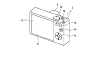
図1は、本発明の実施の形態1に係る表示装置である撮像装置の被写体に面する側(前面側)の構成を示す図である。図2は、本実施の形態1に係る表示装置である撮像装置のユーザに面する側(背面側)の構成を示す図である。図3は、本実施の形態1に係る表示装置である撮像装置の構成を示すブロック図である。
(Embodiment 1)
FIG. 1 is a diagram illustrating a configuration of a side facing the subject (front side) of an imaging apparatus that is a display apparatus according to
図1〜図3に示すように、撮像装置1は、撮像部2と、発光部3と、姿勢検出部4と、タイマー5と、方位検出部6と、操作入力部7と、GPS信号受信部8と、表示部9と、タッチパネル10と、記憶部11と、制御部12と、を備える。
As shown in FIGS. 1 to 3, the
撮像部2は、レンズ部21と、レンズ駆動部22と、絞り23と、絞り駆動部24と、シャッター25と、シャッター駆動部26と、撮像素子27と、撮像駆動部28と、信号処理部29と、を有する。
The
レンズ部21は、フォーカスおよびズーム可能な複数のレンズ群によって構成され、所定の視野領域から光を集光する。
レンズ駆動部22は、ステッピングモータまたはDCモータを用いて構成され、レンズ部21のレンズ群を光軸L1上に沿って移動させることにより、レンズ部21のピント位置および焦点距離等の変更を行う。
The
The
絞り23は、レンズ部21が集光した光の入射量を制限することにより露出の調整を行う。
絞り駆動部24は、ステッピングモータ等によって構成され、絞り23を駆動する。
The
The
シャッター25は、撮像素子27の状態を露光状態または遮光状態に設定する。
シャッター駆動部26は、ステッピングモータ等によって構成され、操作入力部7から入力されるレリーズ信号に応じてシャッター25を駆動する。
The
The
撮像素子27は、CCD(Charge Coupled Device)またはCMOS(Complementary Metal Oxide Semiconductor)等によって構成される。撮像素子27は、レンズ部21が集光した光を受光して光電変換を行うことによって、光を電気信号(アナログ信号)に変換する。
The
撮像駆動部28は、撮像素子27を駆動するタイミングパルスを生成し、撮像素子27が光電変換した電気信号を信号処理部29に出力させる。
The
信号処理部29は、アナログアンプやA/D変換器等によって構成される。信号処理部29は、撮像素子27から出力される電気信号に増幅(ゲイン調整)等の信号処理を施した後、A/D変換を行うことによってデジタルの画像データに変換して制御部12に出力する。
The
発光部3は、撮像装置1が撮像する視野領域へ向けて補助光を照射する。発光部3は、キセノンランプまたはLED(Light Emitting Diode)等を用いて構成される。
The
姿勢検出部4は、加速度センサを用いて構成される。姿勢検出部4は、撮像装置1の加速度を検出することにより、水平面を基準としたときの撮像装置1の姿勢(傾斜角度)を検出する。
The
タイマー5は、計時機能および日時判定機能を有する。
The
方位検出部6は、地磁気センサを用いて構成され、レンズ部21の光軸が向いている方位を検出する。
The
操作入力部7は、撮像装置1の外部から操作入力信号を受け付ける。操作入力部7は、撮像装置1の電源状態をオン状態またはオフ状態に切換える電源スイッチ71と、撮影の指示を与えるレリーズ信号の入力を受け付けるレリーズスイッチ72と、撮像装置1で設定可能な各種動作モードの切換えを行うモード切換スイッチ73と、撮像装置1の各種設定を切換える操作スイッチ74と、撮像装置1の各種設定を表示部9に表示させるメニュースイッチ75と、撮像装置1の画角を変更する指示信号の入力を受け付けるズームスイッチ76と、を有する。
The operation input unit 7 receives an operation input signal from the outside of the
GPS信号受信部8は、複数のGPS衛星100によって送信されるGPS信号を受信する。GPS信号受信部8は、GPS衛星100の軌道情報やGPS衛星100に搭載された原子時計の時刻情報などを含むGPS信号(電波)を受信可能なアンテナと、このアンテナで受信したGPS信号に対する信号処理を行う信号処理回路とを有する。
The GPS
表示部9は、液晶または有機EL(Electro Luminescence)等からなる表示パネルを用いて実現される。表示部9は、撮像部2が生成した画像データに対応する画像を表示する。表示部9は、撮像装置1の操作情報および撮影に関する情報を適宜表示する。
The
タッチパネル10は、表示部9の表示画面上に重ねて設けられる(図2を参照)。タッチパネル10は、ユーザが表示部9に表示される情報に基づいて接触した位置を検出し、この接触位置に応じた指示信号の入力を受け付ける。タッチパネル10としては、一般に知られている抵抗膜方式、静電容量方式、光学式等のうち、いずれの方式のタッチパネルであっても適用可能である。
The
記憶部11は、撮像装置1の内部に固定的に設けられえるフラッシュメモリおよびRAM(Random Access Memory)等の半導体メモリを用いて実現される。記憶部11は、撮像部2が撮像した画像データを記憶する画像データ記憶部111と、撮像装置1が実行する各種プログラムおよび本実施の形態1に係る表示プログラムを記憶するプログラム記憶部112と、各地点の緯度および経度の情報を含む地図情報を記憶する地図情報記憶部113と、複数のランドマークの位置(緯度、経度)および名称(ランドマーク名)を含むランドマーク情報を記憶するランドマーク情報記憶部114と、を有する。ここでいうランドマークには、例えば山、海、浜などの自然物や、建物などの人工物が含まれる。なお、記憶部11は、外部から装着されるメモリカード等のコンピュータ読み取り可能な記録媒体を含むものであってもよい。
The storage unit 11 is realized using a flash memory that can be fixedly provided inside the
制御部12は、CPU(Central Processing Unit)等を用いて構成される。制御部12は、操作入力部7やタッチパネル10からの指示信号または切換信号等に応じて撮像装置1を構成する各部に対応する指示やデータの転送等を行って撮像装置1の動作を統括的に制御する。
The
制御部12の詳細な構成について説明する。制御部12は、画像処理部121と、測位部122と、位置算出部123と、姿勢判定部124と、撮像制御部125と、検索部126と、方向判定部127と、画像合成部128と、表示制御部129と、を有する。
A detailed configuration of the
画像処理部121は、撮像部2の信号処理部29から出力される画像データに対して、エッジ強調、ホワイトバランスおよびγ補正を含む画像処理を行う。また、画像処理部121は、JPEG(Joint Photographic Experts Group)圧縮方式等に基づいて画像データの圧縮処理や伸長処理を行う。
The
測位部122は、GPS信号受信部8が受信したGPS信号に基づいて撮像装置1の位置や高度を定期的に測定する。この際、測位部122は、4つ以上のGPS衛星から受信したGPS信号を用いて撮像装置1の位置や高度を定期的に測定する。
The
位置算出部123は、測位部122が異なる2つの時刻で測定した撮像装置1の位置およびタイマー5の時刻情報などを用いて撮像装置1および撮像装置1が撮像する被写体の位置を算出する。
The
姿勢判定部124は、姿勢検出部4の検出結果に基づいて撮像装置1の姿勢を判定する。具体的には、姿勢判定部124は、撮像装置1が撮像動作を行う姿勢(撮像姿勢)をとっているか、または撮像装置1が地図情報記憶部113が記憶する地図上の撮像装置1の位置を表示する動作を行う姿勢(位置表示姿勢)をとっているかを判定する。ここで、位置表示姿勢とは、表示部9の表示画面の表面が略水平な状態(水平面と10°以内の角度をなす状態)にある姿勢を意味する。また、撮像姿勢は、位置表示姿勢以外の姿勢を意味する。
The
撮像制御部125は、レリーズスイッチ72が撮影指示信号(レリーズ信号)の入力を受け付けた場合、撮像装置1における撮影動作を開始する制御を行う。ここで、撮像装置1における撮影動作とは、シャッター駆動部26および撮像駆動部28の駆動によって撮像素子27が出力した画像データに対し、信号処理部29および画像処理部121が所定の処理を施す動作をいう。このようにして処理が施された画像データは、制御部12によって撮影日時情報等と関連付けられて画像データ記憶部111に記憶される。
When the
検索部126は、画像に写っている被写体の位置に対応するランドマークをランドマーク情報記憶部114から検索する。
The
方向判定部127は、位置算出部123における撮像装置1の位置の時間変化に基づいて撮像装置1の移動方向を判定する。
The
画像合成部128は、画像の合成を行う。例えば、画像合成部128は、撮像部2が撮像した画像に含まれる被写体に関連する情報を、その画像に合成する。被写体に関連する情報としては、例えばその被写体の位置(緯度、経度)や名称などを挙げることができる。
The
表示制御部129は、表示部9における表示を制御する。例えば、表示制御部129は、画像データ記憶部111が記憶する複数の画像データの各々に対応する画像を表示部9に表示させる。また、表示制御部129は、複数の画像をそれぞれ縮小した縮小画像(サムネイル画像)を表示部9に表示させる。
The
以上の構成を有する撮像装置1では、動作モードとして、画像を撮影する撮影モードと、画像を再生する再生モードとを設定することができる。このうち、撮影モードとして、通常撮影モードの他に、飛行機の機内での撮影に対応した機内撮影モードを設定することが可能である。この機内撮影モードは、飛行中の機内で飛行機の窓から見える風景を撮影する状況を想定した撮影モードである。
In the
図4は、撮像装置1が行う処理の概要を示すフローチャートである。まず、撮像装置1の電源がオンになっている場合(ステップS1:Yes)、ステップS2へ進む。一方、撮像装置1の電源がオンになっていない場合(ステップS1:No)、撮像装置1は処理を終了する。
FIG. 4 is a flowchart illustrating an outline of processing performed by the
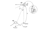
撮像装置1が撮影モードに設定されている場合(ステップS2:撮影モード)を説明する。この場合において、機内撮影モードに設定されているとき(ステップS3:Yes)、制御部12は、姿勢検出部4および方位検出部6による撮像装置1の状態検出、およびGPS信号受信部8によるGPS信号の受信を開始する制御を行う(ステップS4)。機内撮影モードは、飛行機に搭乗している撮影者が、飛行機の窓から眼下に広がる風景を撮影するような状況で設定することが想定される。図5は、機内撮影モードに設定された撮像装置1が撮像する状況を模式的に示す図である。図5において、飛行機200に搭乗している撮影者300は、被写体400の周辺の風景を撮影しようとしている。
A case where the
続いて、表示制御部129は、表示部9にスルー画像を表示させる(ステップS5)。ここでいうスルー画像とは、レリーズスイッチ72が押されない状態で撮像部2が生成する画像データに対応する画像のことである。
Subsequently, the
この後、測位部122がGPS信号に基づいて異なる2つの時刻における撮像装置1の位置を測定済みである場合(ステップS6:Yes)、位置算出部123は、測定済みの2つの位置(測定位置)を用いて撮像装置1の撮像時の位置(以下、「現在位置」という)を算出する(ステップS7)。なお、測位部122が3つ以上の異なる時刻における撮像装置1の位置を測定済みである場合、位置算出部123は、直近の2つの測定位置を用いて撮像装置1の現在位置を算出する。
After this, when the
ここで、位置算出部123が行う具体的な位置の算出方法を説明する。図6は、撮像装置1および被写体の位置の算出方法を説明する図である。図6では、図5に示す被写体400の位置を算出する場合を示している。図6では、測位部122が直近に測定した2つの測定位置をP1,P2としている。位置P1は時刻T1に測定された位置であり、その緯度はI1,経度はK1である。位置P2は時刻T2(>T1)に測定された位置であり、その緯度はI2,経度はK2である。また、図6では、現在位置をP0としている。現在位置P0の時刻はT0(>T2)であり、その緯度をI0とし、経度をK0としている。また、図6では、被写体400の位置PLの緯度をILとし、経度をKLとしている。ここで、緯度は、北緯を正で表す一方、南緯を負で表すものとする。すなわち、緯度は、−90度(南緯90度)〜+90度(北緯90度)で表される。また、経度は、東経を正で表す一方、西経を負で表すものとする。すなわち、経度は、−180度(西経180度)〜+180度(東経180度)で表される。
Here, a specific position calculation method performed by the
まず、位置算出部123は、位置P1,P2の緯度経度情報および時刻情報を用いて、飛行機200の緯度方向の速さBIおよび経度方向の速さBKをそれぞれ算出する。
BI=(I2−I1)/(T2−T1) ・・・(1)
BK=(K2−K1)/(T2−T1) ・・・(2)
続いて、位置算出部123は、式(1)、(2)の算出結果と現在位置P0の時刻情報を用いて、現在位置P0の緯度I0,経度K0をそれぞれ算出する。
I0=I2+BI・(T0−T2)
=I2+(I2−I1)・(T0−T2)/(T2−T1) ・・・(3)
K0=K2+BK・(T0−T2)
=K2+(K2−K1)・(T0−T2)/(T2−T1) ・・・(4)
First, the
BI = (I 2 −I 1 ) / (T 2 −T 1 ) (1)
BK = (K 2 −K 1 ) / (T 2 −T 1 ) (2)
Subsequently, the
I 0 = I 2 + BI · (T 0 −T 2 )
= I 2 + (I 2 −I 1 ) · (T 0 −T 2 ) / (T 2 −T 1 ) (3)
K 0 = K 2 + BK · (T 0 −T 2 )
= K 2 + (K 2 -K 1) · (T 0 -T 2) / (T 2 -T 1) ··· (4)
その後、姿勢判定部124は、撮像装置1の姿勢を判定する(ステップS8)。まず、姿勢判定部124による姿勢判定の結果、撮像装置1が撮像姿勢をとっている場合(ステップS8:Yes)を説明する。図7は、撮像装置1が撮像姿勢をとっている状況を示す図である。図7に示すように、撮影者300は、撮像装置1を構えて飛行機200の窓201から見える風景を撮影しようとしている。
Thereafter, the
撮像装置1が撮像姿勢をとっている場合(ステップS8:Yes)、姿勢判定部124は撮像装置1の俯角を判定する(ステップS9)。ここでいう俯角とは、レンズ部21の光軸L1の方向とレンズ部21の中心位置を通過する水平面とがなす角のことである。
When the
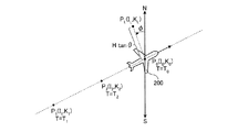
続いて、位置算出部123は、撮影時の被写体の位置を算出する(ステップS10)。図5および図6において、被写体400の位置PLの緯度IL、経度KLは、レンズ部21の光軸L1の方向とレンズ部21の中心位置を通過する鉛直面とのなす傾斜角をθとし、飛行機200の高度をHとし、方位検出部6が検出した被写体の方位を示す方位角として経線の北向きを基準とする方位角をφ(北向きに対して反時計回りを正)とするとき、以下の式(5),(6)にしたがってそれぞれ算出される。
IL=I0+Htanθcosφ ・・・(5)
KL=K0−Htanθsinφ ・・・(6)
ここで、位置算出部123は、式(5)の右辺のI0および式(6)の右辺のK0に対し、式(3)、(4)の算出結果をそれぞれ代入する。なお、ステップS9で姿勢判定部124が判定した俯角をαとおくと、俯角αと傾斜角θとは、度(°)を単位としてα+θ=90°を満たす。
Subsequently, the
I L = I 0 + H tan θ cos φ (5)
K L = K 0 −H tan θ sin φ (6)
Here, the
続いて、検索部126は、ランドマーク情報記憶部114から被写体の位置に対応するランドマークを検索する(ステップS11)。具体的には、検索部126は、図5および図6に示す場合、被写体400の位置PL(IL,KL)を中心とする領域D={(I,K)|IL−ΔI≦I≦IL+ΔI,KL−ΔK≦K≦KL+ΔK}に含まれるランドマークをランドマーク情報記憶部114から検索する。領域Dの大きさを決めるパラメータΔI,ΔKは、ユーザが操作入力部7からの入力によって所望の値を設定することが可能である。なお、領域D内に複数のランドマークが存在する場合、検索部126は、被写体400の位置PL(IL,KL)に最も近いランドマークを選択する。
Subsequently, the
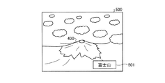
検索部126が検索した結果、被写体の位置に対応するランドマークを取得した場合(ステップS12:Yes)、画像合成部128は、スルー画像にランドマーク名を合成した合成スルー画像を生成する。この後、表示制御部129は、その合成スルー画像を表示部9に表示させ(ステップS13)、後述するステップS14へ移行する。図8は、表示部9における合成スルー画像の表示例を示す図である。同図に示す合成スルー画像500は、被写体400の画像と、被写体400に対応するランドマーク名(図8の場合は「富士山」)を表示するランドマーク名表示画像501とが合成されている。
As a result of the search by the
ステップS12において、検索部126が被写体の位置に対応するランドマークを取得できなかった場合(ステップS12:No)、撮像装置1は後述するステップS14へ移行する。
In step S12, when the
ステップS14において、レリーズスイッチ72が押されて撮影指示信号が入力されると(ステップS14:Yes)、撮像制御部125は撮影動作を開始する制御を行う(ステップS15)。
In step S14, when the
続いて、表示制御部129は、撮影指示信号の入力に応じて撮像部2が生成した画像データに対応する画像(レックビュー画像)を表示部9に表示させる(ステップS16)。また、撮像制御部125は、その画像データを画像データ記憶部111に記憶させる(ステップS17)。なお、ステップS16とステップS17との順序を逆にして実行してもよいし、ステップS16とステップS17とを並行して実行してもよい。
Subsequently, the
この後、モード切換スイッチ73またはタッチパネル10によってモード切換指示が入力された場合(ステップS18:Yes)、撮像装置1は動作モードを切換えて(ステップS19)、ステップS1へ戻る。一方、モード切換スイッチ73またはタッチパネル10によってモード切換指示が入力されない場合(ステップS18:No)、撮像装置1はステップS1へ戻る。
Thereafter, when a mode switching instruction is input by the
ステップS14でレリーズスイッチ72が押されない場合(ステップS14:No)、撮像装置1はステップS18へ移行する。
If the
次に、ステップS8における姿勢判定の結果、撮像装置1が撮像姿勢をとっていない場合、すなわち撮像装置1が位置表示姿勢をとっている場合(ステップS8:No)を説明する。図9は、撮像装置1が位置表示姿勢をとっている状況を模式的に示す図である。図9において、撮影者300は、表示部9の表示画面を略水平にした状態で撮像装置1を把持している。撮像装置1が位置表示姿勢をとっている場合、方向判定部127は、位置算出部123が算出した2つの位置から飛行機200の飛行方向(撮像装置1の移動方向)を判定する(ステップS20)。具体的には、方向判定部127は、上述した緯度方向の速さBIおよび経度方向の速さBKを用いることによって飛行機200の飛行方向を判定する。
Next, as a result of the posture determination in step S8, the case where the
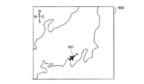
続いて、画像合成部128は、ステップS7で求めた現在位置(I0,K0)、およびステップS9で判定した飛行方向をもとに、被写体400が含まれる地図画像に飛行機像を合成した現在位置表示画像を生成する。この後、表示制御部129は、その現在位置表示画像を表示部9に表示させる(ステップS21)。図10は、表示部9における現在位置表示画像の表示例を示す図である。同図に示す現在位置表示画像600には、地図に飛行機像601が重ねて表示されている。飛行機像601には、飛行機の進行方向が矢印で表示されている。この後、撮像装置1は、ステップS18へ移行する。
Subsequently, the
ステップS6において、測位部122が異なる2つの時刻における撮像装置1の位置を測定済みでない場合(ステップS6:No)を説明する。この場合には、1つの位置のみを測定済みである場合も含まれるものとする。測位部122が異なる2つの時刻における撮像装置1の位置を測定済みでない場合、画像合成部128は、スルー画像に警告を重ねた警告スルー画像を生成する。表示制御部129は、画像合成部128が生成した警告スルー画像を表示部9に表示させる(ステップS22)。ここで表示する警告の内容は、例えば「現在測位中です。電源を切らないで下さい。」というものである。なお、撮像装置1に音声出力部を設けておき、この音声出力部によって警告を音声出力するようにしてもよい。この後、撮像装置1は、ステップS14へ移行する。
In step S6, the case where the
次に、ステップS3において、撮像装置1が機内撮影モードに設定されていない場合、すなわち撮像装置1が通常の撮影モードに設定されている場合(ステップS3:No)を説明する。この場合、表示制御部129は、表示部9にスルー画像を表示させる(ステップS23)。この後、撮像装置1はステップS14へ移行する。
Next, the case where the
次に、ステップS2で撮像装置1が再生モードに設定されている場合(ステップS2:再生モード)を説明する。この場合、表示制御部129は、表示部9に画像選択画面を表示させる(ステップS24)。この画像選択画面では、複数の再生候補画像が一覧表示されている。
Next, the case where the
続いて、操作入力部7またはタッチパネル10の入力によって画像が選択された場合(ステップS25:Yes)、表示制御部129は、選択された画像を表示部9に全画面で表示させる(ステップS26)。一方、画像が選択されない場合(ステップS25:No)、撮像装置1は後述するステップS28へ移行する。
Subsequently, when an image is selected by the input of the operation input unit 7 or the touch panel 10 (step S25: Yes), the
その後、操作入力部7またはタッチパネル10の入力によって画像の切換指示が入力された場合(ステップS27:Yes)、撮像装置1はステップS26へ戻り、表示部9での表示を選択された画像に切り換えて全画面で表示する(ステップS26)。一方、画像の切換指示が入力されない場合(ステップS27:No)、撮像装置1は後述するステップS28へ移行する。
Thereafter, when an image switching instruction is input by the operation input unit 7 or the touch panel 10 (step S27: Yes), the
ステップS28において、操作入力部7またはタッチパネル10によって画像再生の終了指示が入力された場合(ステップS28:Yes)、撮像装置1はステップS18へ移行する。これに対して、画像再生の終了指示が入力されない場合(ステップS28:No)、撮像装置1はステップS25へ戻る。
In step S28, when an instruction to end image reproduction is input through the operation input unit 7 or the touch panel 10 (step S28: Yes), the
以上説明した本発明の実施の形態1によれば、異なる2つの時刻に測定した位置を用いて当該表示装置の所定時刻における位置を算出し、算出した位置に応じた情報を該情報と対応する画像に合成して表示するため、移動しながらその移動状況に応じた画像を表示する際に、表示する画像に関連する情報を抽出して表示することができる。 According to the first embodiment of the present invention described above, the position at the predetermined time of the display device is calculated using the positions measured at two different times, and the information corresponding to the calculated position is associated with the information. Since the image is synthesized and displayed, information related to the image to be displayed can be extracted and displayed when the image corresponding to the movement state is displayed while moving.
また、本実施の形態1によれば、異なる2つの時刻に測定した当該表示装置の位置を用いて算出した被写体の位置に応じた情報をその被写体の画像に合成して表示することにより、撮影者が移動しながら撮影を行う場合に被写体の情報を表示することができる。 Further, according to the first embodiment, information corresponding to the position of the subject calculated using the position of the display device measured at two different times is combined with the subject image and displayed. Information about the subject can be displayed when a person moves while taking a picture.
また、本実施の形態1によれば、表示装置が位置表示姿勢をとっている場合、当該表示装置の位置を含む地図を生成し、この生成した地図に当該表示装置の位置を合成した現在位置表示画像を生成するため、ユーザは所望のタイミングで現在位置を把握することができる。 Further, according to the first embodiment, when the display device is in the position display posture, a map including the position of the display device is generated, and the current position where the position of the display device is combined with the generated map Since the display image is generated, the user can grasp the current position at a desired timing.
なお、以上の説明においては、被写体の画像にランドマーク名を合成して表示する場合を説明したが、ランドマーク名に加えてそのランドマークの簡単な説明を表示するようにしてもよい。この場合には、ランドマーク情報記憶部114に、予めランドマークの説明も記憶しておけばよい。
In the above description, the case where the landmark name is synthesized and displayed on the image of the subject has been described. However, in addition to the landmark name, a brief description of the landmark may be displayed. In this case, the landmark
(実施の形態2)
本発明の実施の形態2は、撮影後のレックビュー画像を表示する際にランドマーク名を重ねて表示したり、再生時の再生画像にランドマーク名を重ねて表示したりすることを特徴とする。なお、本実施の形態2に係る表示装置である撮像装置の構成は、実施の形態1で説明した撮像装置1と同様である。
(Embodiment 2)
図11は、撮像装置1が行う処理の概要を示すフローチャートである。まず、撮像装置1の電源がオンになっている場合(ステップS31:Yes)、ステップS32へ進む。一方、撮像装置1の電源がオンになっていない場合(ステップS31:No)、撮像装置1は処理を終了する。
FIG. 11 is a flowchart illustrating an outline of processing performed by the
撮像装置1が撮影モードに設定され(ステップS32:撮影モード)、かつ機内撮影モードに設定されている場合(ステップS33:Yes)、制御部12は、姿勢検出部4および方位検出部6による撮像装置1の状態検出動作、およびGPS信号受信部8によるGPS信号の受信を開始する制御を行う(ステップS34)。
When the
この後、表示制御部129は、表示部9にスルー画像を表示させる(ステップS35)。
Thereafter, the
続いて、レリーズスイッチ72が押されて撮影指示信号が入力された場合(ステップS36:Yes)、撮像制御部125は、撮影動作を開始する制御を行う(ステップS37)。その後、制御部12は、撮影した画像データおよび撮影情報を画像データ記憶部111に記憶させる(ステップS38)。ここでいう撮影情報は、例えば撮像装置1の俯角である。
Subsequently, when the
続くステップS39において、測位部122が異なる2つの時刻における撮像装置1の位置を測定済みである場合(ステップS39:Yes)、位置算出部123は、2つの測定位置を用いて撮像装置1の現在位置を算出する(ステップS40)。このステップS40における現在位置の具体的な算出方法は、実施の形態1と同様である(式(3),(4)を参照)。
In subsequent step S39, if the
この後、撮像装置1は、撮影時の被写体の位置を算出する(ステップS41)。ここでの被写体の位置の具体的な算出方法も実施の形態1と同様である(式(5),(6)を参照)。
Thereafter, the
続いて、検索部126は、ランドマーク情報記憶部114から被写体の位置に対応するランドマークの検索を行う(ステップS42)。
Subsequently, the
検索部126が検索した結果、被写体の位置に対応するランドマークを取得した場合(ステップS43:Yes)、画像合成部128は、レックビュー画像にランドマーク名を合成した合成レックビュー画像を生成する。この後、表示制御部129は、その合成レックビュー画像を表示部9に表示させる(ステップS44)。合成レックビュー画像は、図8に示す合成スルー画像500と同様に表示される。
As a result of the search by the
続いて、制御部12は、撮影した画像データとその画像データに対応するランドマーク情報とを関連付けて画像データ記憶部111に記憶させる(ステップS45)。
Subsequently, the
この後、モード切換スイッチ73またはタッチパネル10によってモード切換指示が入力された場合(ステップS46:Yes)、撮像装置1は動作モードを切換えて(ステップS47)、ステップS1へ戻る。一方、モード切換スイッチ73またはタッチパネル10によってモード切換指示が入力されない場合(ステップS46:No)、撮像装置1はステップS1へ戻る。
Thereafter, when a mode switching instruction is input through the
ステップS42で検索部126が検索した結果、被写体の位置に対応するランドマークを取得できなかった場合(ステップS43:No)、撮像装置1は上述したステップS46へ移行する。
If the landmark corresponding to the position of the subject cannot be acquired as a result of the search by the
次に、ステップS39において、測位部122が異なる2つの時刻における撮像装置1の位置を測定済みでない場合(ステップS39:No)を説明する。ここで、「異なる2つの時刻における撮像装置1の位置を測定済みでない場合」には、1つの位置のみを測定済みである場合も含まれるものとする。測位部122が異なる2つの時刻における撮像装置1の位置を測定済みでない場合、画像合成部128は、スルー画像に警告を合成した警告スルー画像を生成する。表示制御部129は、画像合成部128が生成した警告スルー画像を表示部9に表示させる(ステップS48)。ここで表示する警告の内容は、例えば「現在測位中です。電源を切らないで下さい。」というものである。
Next, a case where the position of the
続いて、測位部122が、警告を表示してから所定時間内に2つの位置の測定を完了した場合(ステップS49:Yes)、位置算出部123は、2つの測定位置を用いて撮影時の被写体400の位置PLを算出する(ステップS50)。なお、ステップS39において、測位部122が1つの位置のみを算出している場合、ステップS49において、測位部122は警告を表示してから所定時間内に少なくとも1つの位置を測定できればよい。ここでの所定時間は、1分程度である。
Subsequently, when the
ここで、ステップS50における具体的な位置の算出方法を説明する。図12は、撮像装置1および被写体の位置の算出方法を説明する図である。図12では、測位部122が直近に測定した2つの測定位置をP3,P4としている。位置P3は時刻T3に測定された位置であり、その緯度はI3,経度はK3である。位置P4は時刻T4(>T3)に測定された位置であり、その緯度はI4,経度はK4である。また、図12では、撮像時の撮像装置1の位置(撮像位置)をP0'としている。撮像位置P0'の時刻はT0'(<T3)であり、その緯度をI0'とし,経度をK0'としている。また、図12では、図5に示す被写体400の位置をPL'とし、その緯度をIL'とし,経度をKL'としている。なお、緯度Iおよび経度Kの表し方は、実施の形態1と同様である。
Here, a specific method of calculating the position in step S50 will be described. FIG. 12 is a diagram illustrating the
まず、位置算出部123は、位置P3,P4の緯度経度情報および時刻情報を用いて、飛行機200の緯度方向の速さBI'および経度方向の速さBK'をそれぞれ算出する。
BI’=(I4−I3)/(T4−T3) ・・・(7)
BK’=(K4−K3)/(T4−T3) ・・・(8)
続いて、位置算出部123は、式(7)、(8)の算出結果と撮像位置P0'の時刻情報を用いて、撮像位置P0'の緯度I0',経度K0'をそれぞれ算出する。
I0'=I3−BI'・(T3−T0')
=I3−(I4−I3)・(T3−T0')/(T4−T3) ・・・(9)
K0'=K3−BK'・(T3−T0')
=K3−(K4−K3)・(T3−T0')/(T4−T3) ・・・(10)
最後に、位置算出部123は、レンズ部21の光軸L1の方向とレンズ部21の中心位置を通過する鉛直面とのなす傾斜角θ、飛行機200の高度H、方位検出部6が検出した被写体400の方位を示す方位角として経線の北向きを基準とする方位角φ'(北向きに対して反時計回りを正)を用いることにより、被写体の緯度IL'、経度KL'をそれぞれ算出する。
IL'=I0'+Htanθcosφ' ・・・(11)
KL'=K0'−Htanθsinφ' ・・・(12)
ここで、位置算出部123は、式(11)の右辺のI0'および式(12)の右辺のK0'に対し、式(9)、(10)の算出結果をそれぞれ代入する。
First, the
BI ′ = (I 4 −I 3 ) / (T 4 −T 3 ) (7)
BK ′ = (K 4 −K 3 ) / (T 4 −T 3 ) (8)
Subsequently, the
I 0 '= I 3 −BI ′ · (T 3 −T 0 ′)
= I 3 − (I 4 −I 3 ) · (T 3 −T 0 ′) / (T 4 −T 3 ) (9)
K 0 '= K 3 -BK' · (T 3 -T 0 ')
= K 3 - (K 4 -K 3) · (T 3 -T 0 ') / (T 4 -T 3) ··· (10)
Finally, the
I L '= I 0 ' + H tan θ cos φ '(11)
K L '= K 0 ' -Htanθsinφ '(12)
Here, the
なお、図12および式(9)〜(12)は、測位部122が異なる2つの位置をステップS37の撮影後に測定した場合を示しているが、それ以外にも、ステップS37の撮影の前後で測位部122が測定した異なる2つの位置を用いることもありうる。この場合にも、式(9)〜(12)はそのまま成立する。
Note that FIG. 12 and equations (9) to (12) show the case where two different positions of the
このステップS50の後、撮像装置1は上述したステップS42へ移行する。
After step S50, the
次に、ステップS33において、撮像装置1が機内撮影モードに設定されていない場合、すなわち撮像装置1が通常の撮影モードに設定されている場合(ステップS33:No)を説明する。この場合、表示制御部129は、表示部9にスルー画像を表示させる(ステップS51)。
Next, the case where the
続いて、レリーズスイッチ72が押されて撮影指示信号が入力されると(ステップS52:Yes)、撮像制御部125は撮影動作を開始する制御を行う(ステップS53)。その後、表示制御部129は、撮影指示信号の入力に応じて撮像部2が生成した画像データに対応するレックビュー画像を表示部9に表示させる(ステップS54)。また撮像制御部125は、その画像データを画像データ記憶部111に記憶させる(ステップS55)。なお、ステップS54とステップS55との順序を逆にして実行してもよいし、ステップS54とステップS55とを並行して実行してもよい。この後、撮像装置1は、ステップS46へ移行する。
Subsequently, when the
ステップS52でレリーズスイッチ72が押されない場合(ステップS52:No)、撮像装置1はステップS46へ移行する。
If the
次に、ステップS2で撮像装置1が再生モードに設定されている場合(ステップS2:再生モード)を説明する。この場合、表示制御部129は、表示部9に画像選択画面を表示させる(ステップS56)。この画像選択画面では、複数の再生候補画像が一覧表示されている。
Next, the case where the
続いて、操作入力部7またはタッチパネル10によって画像が選択された場合(ステップS57:Yes)において、選択された画像に関連付けられたランドマーク情報が存在するとき(ステップS58:Yes)、表示制御部129は、選択された画像にランドマーク名を合成した合成再生画像を表示部9に全画面で表示させる(ステップS59)。この合成再生画像も、図8に示す合成スルー画像と同様に表示される。
Subsequently, when an image is selected by the operation input unit 7 or the touch panel 10 (step S57: Yes), when landmark information associated with the selected image exists (step S58: Yes), the display control unit In step S59, the composite reproduction image in which the landmark name is combined with the selected image is displayed on the
その後、画像の切換指示が入力された場合(ステップS60:Yes)、撮像装置1はステップS58へ戻り、選択された画像に関連付けられたランドマーク情報の有無を判定する(ステップS58)。一方、画像の切換指示が入力されない場合(ステップS60:No)において、操作入力部7またはタッチパネル10によって画像再生の終了指示が入力されたとき(ステップS61:Yes)、撮像装置1はステップS46へ移行する。ステップS60で画像の終了指示が入力されないとき(ステップS61:No)、撮像装置1はステップS57へ戻る。
Thereafter, when an image switching instruction is input (step S60: Yes), the
ステップS57で操作入力部7またはタッチパネル10によって画像が選択されない場合(ステップS57:No)、撮像装置1はステップS61へ移行する。
If no image is selected by the operation input unit 7 or the
次に、ステップS58において選択された画像に関連付けられたランドマーク情報が存在しない場合(ステップS58:No)を説明する。この場合、その選択された画像の撮影時刻からの経過時間が所定時間以内であれば(ステップS62:Yes)、制御部12は、姿勢検出部4および方位検出部6による撮像装置1の状態検出動作、およびGPS信号受信部8によるGPS信号の受信動作を開始する制御を行う(ステップS63)。ここでの所定時間は、再生時のタイムラグがなるべく少なくなるような時間であることが好ましく、たかだか1分程度である。
Next, a case where landmark information associated with the image selected in step S58 does not exist (step S58: No) will be described. In this case, if the elapsed time from the shooting time of the selected image is within a predetermined time (step S62: Yes), the
この後、測位部122が、画像が選択されてから所定時間内に2つの位置の測定を完了した場合(ステップS64:Yes)、位置算出部123は、2つの測定位置を用いて撮影時の被写体の位置を算出する(ステップS65)。ここでの被写体の位置の算出方法は、ステップS50で説明した方法と同様である。また、ステップS65における所定時間は、できるだけ短い方が好ましく、例えば1分程度である。
Thereafter, when the
続いて、検索部126は、ランドマーク情報記憶部114から被写体の位置情報に応じたランドマークの検索を行う(ステップS66)。検索部126が検索した結果、被写体の位置に対応するランドマークを取得した場合(ステップS67:Yes)、画像合成部128は、再生画像にランドマーク名を合成した合成再生画像を生成する。この後、表示制御部129は、その合成再生画像を表示部9に全画面表示させる(ステップS68)。
Subsequently, the
続いて、制御部12は、ランドマーク情報を画像データと関連付けて画像データ記憶部111に記憶させる(ステップS69)。ステップS69の後、撮像装置1は、ステップS60へ移行する。
Subsequently, the
ステップS62で撮影時刻からの経過時間が所定時間以内でない場合(ステップS62:No)、ステップS64で測位部122が所定時間内に2つの位置の測定を完了しなかった場合(ステップS64:No)、またはステップS67で検索部126がランドマーク情報を取得できなかった場合(ステップS67:No)、表示制御部129は、選択された画像を表示部9に全画面表示させる(ステップS70)。この後、撮像装置1は、ステップS60へ移行する。
When the elapsed time from the photographing time is not within the predetermined time in step S62 (step S62: No), or when the
以上説明した本発明の実施の形態2によれば、異なる2つの時刻に測定した位置を用いて当該表示装置の所定時刻における位置を算出し、算出した位置に応じた情報を該情報と対応する画像に合成して表示するため、移動しながらその移動状況に応じた画像を表示する際に、表示する画像に関連する情報を抽出して表示することができる。 According to the second embodiment of the present invention described above, the position at the predetermined time of the display device is calculated using the positions measured at two different times, and the information corresponding to the calculated position is associated with the information. Since the image is synthesized and displayed, information related to the image to be displayed can be extracted and displayed when the image corresponding to the movement state is displayed while moving.
また、本実施の形態2によれば、異なる2つの時刻に測定した当該表示装置の位置を用いて算出した被写体の位置に応じた情報をその被写体の画像に合成して表示することにより、撮影者が移動しながら撮影を行う場合に被写体の情報を表示することができる。 Further, according to the second embodiment, information corresponding to the position of the subject calculated using the position of the display device measured at two different times is combined with the subject image and displayed. Information about the subject can be displayed when a person moves while taking a picture.
また、本実施の形態2によれば、撮影時には撮像装置の位置を算出することができなかったとしても、その後に算出した位置を用いることによって撮影時の位置を算出することができる。このため、撮影後に被写体の名称を認識することも可能となる。このように、本実施の形態2によれば、撮影という短い時間で行われる行為と、ランドマーク検索という比較的長い時間を必要とする行為とを切り離して処理を行うことにより、撮影者は撮影に集中することができるだけでなく、撮影後に被写体に関連した情報を得ることができ、被写体に対する理解を深めることができる。 Further, according to the second embodiment, even when the position of the imaging device cannot be calculated at the time of shooting, the position at the time of shooting can be calculated by using the position calculated thereafter. For this reason, it is possible to recognize the name of the subject after shooting. As described above, according to the second embodiment, the photographer can shoot by separating the action that is performed in a short time of shooting and the action that requires a relatively long time of landmark search. In addition to being able to concentrate on the subject, information related to the subject can be obtained after shooting, and the understanding of the subject can be deepened.
ここまで、本発明を実施するための形態として、2つの実施の形態を説明してきたが、本発明は、上述した実施の形態1、2によってのみ限定されるべきものではない。例えば、測位部は位置のみを測定することとし、高度については、半導体圧力センサまたは気圧センサを用いて検出するかまたは飛行機の平均高度とするようにしてもよい。このような構成を有する表示装置によれば、3個のGPS衛星からのGPS信号を用いればよくなるため、測位部の処理時間を短縮することができる。 Up to this point, two embodiments have been described as modes for carrying out the present invention. However, the present invention should not be limited only by the above-described first and second embodiments. For example, the positioning unit may measure only the position, and the altitude may be detected using a semiconductor pressure sensor or a barometric sensor, or may be the average altitude of the airplane. According to the display device having such a configuration, it is only necessary to use GPS signals from three GPS satellites, so that the processing time of the positioning unit can be shortened.
また、本発明に係る表示装置に対して、インターネット等の通信ネットワークを介して通信を行う機能を具備させ、地図情報やランドマーク情報を通信ネットワーク経由で外部から取得することができるようにしてもよい。 Further, the display device according to the present invention has a function of performing communication via a communication network such as the Internet so that map information and landmark information can be acquired from the outside via the communication network. Good.
このように、本発明は、ここでは記載していない様々な実施の形態等を含みうるものである。 As described above, the present invention can include various embodiments and the like not described herein.
1 撮像装置(表示装置)
2 撮像部
3 発光部
4 姿勢検出部
5 タイマー
6 方位検出部
7 操作入力部
8 GPS信号受信部
9 表示部
10 タッチパネル
11 記憶部
12 制御部
21 レンズ部
22 レンズ駆動部
23 絞り
24 絞り駆動部
25 シャッター
26 シャッター駆動部
27 撮像素子
28 撮像駆動部
29 信号処理部
100 GPS衛星
111 画像データ記憶部
112 プログラム記憶部
113 地図情報記憶部
114 ランドマーク情報記憶部
121 画像処理部
122 測位部
123 位置算出部
124 姿勢判定部
125 撮像制御部
126 検索部
127 方向判定部
128 画像合成部
129 表示制御部
200 飛行機
300 撮影者
400 被写体
500 合成スルー画像
501 ランドマーク名表示画像
600 現在位置表示画像
601 飛行機像
1 Imaging device (display device)
DESCRIPTION OF
Claims (5)
所定の視野領域から光を集光するレンズ部を有し、被写体を撮像して該被写体の画像データを生成する撮像部と、
GPS信号を受信するGPS信号受信部と、
前記GPS信号受信部が受信したGPS信号を用いて当該表示装置の位置および高度を定期的に測定する測位部と、
水平面を基準としたときの当該表示装置の姿勢を検出する姿勢検出部と、
前記レンズ部の光軸が向いている方位を検出する方位検出部と、
前記測位部が異なる2つの時刻に測定した位置に基づいて、撮像時の当該表示装置の位置を算出するとともに、この算出結果と、前記撮像部が前記被写体を撮像した撮像時に前記測位部が測定した当該表示装置の高度と、前記姿勢検出部が検出した検出結果と、前記方位検出部が検出した検出結果とを用いて前記被写体の位置を算出する位置算出部と、
複数のランドマークの位置および名称に関する情報を記憶するランドマーク情報記憶部と、
前記位置算出部が算出した前記被写体の位置に対応するランドマークを前記ランドマーク情報記憶部から検索する検索部と、
前記検索部が検索して取得したランドマークの名称に関する情報を前記画像データに対応する画像に合成した合成画像データを生成する画像合成部と、
当該表示装置が移動しながら前記撮像部が前記被写体を撮像した場合、前記画像合成部が生成した前記合成画像データに対応する合成画像を前記表示部に表示させる表示制御部と、
を備えたことを特徴とする表示装置。 A display device including a display unit capable of displaying an image,
An imaging unit that has a lens unit that collects light from a predetermined field of view , images the subject, and generates image data of the subject;
A GPS signal receiver for receiving GPS signals;
A positioning unit that periodically measures the position and altitude of the display device using the GPS signal received by the GPS signal receiving unit;
An attitude detection unit that detects the attitude of the display device with respect to the horizontal plane;
An azimuth detecting unit for detecting an azimuth in which the optical axis of the lens unit is oriented;
Based on the positions measured by the positioning unit at two different times, the position of the display device at the time of imaging is calculated, and the calculation result and the positioning unit measure at the time of imaging when the imaging unit images the subject. A position calculation unit that calculates the position of the subject using the altitude of the display device, the detection result detected by the posture detection unit, and the detection result detected by the azimuth detection unit ;
A landmark information storage unit for storing information on positions and names of a plurality of landmarks;
A search unit that searches the landmark information storage unit for a landmark corresponding to the position of the subject calculated by the position calculation unit;
An image compositing unit that generates composite image data in which the information related to the name of the landmark acquired by the search unit is combined with an image corresponding to the image data ;
A display control unit that causes the display unit to display a synthesized image corresponding to the synthesized image data generated by the image synthesizing unit when the imaging unit images the subject while the display device is moving ;
A display device comprising:
前記画像合成部が合成に用いる前記画像は、前記撮像部が生成する前記画像データに対応してリアルタイムで前記表示部に表示されるスルー画像または前記操作入力部による撮影指示信号の入力に応じて前記撮像部が生成した前記画像データに対応する画像であることを特徴とする請求項1に記載の表示装置。 It has an operation input unit that can input a shooting instruction signal.
The image used by the image synthesis unit for synthesis is in response to a through image displayed in real time on the display unit corresponding to the image data generated by the imaging unit or an input of a shooting instruction signal from the operation input unit. The display device according to claim 1, wherein the display device is an image corresponding to the image data generated by the imaging unit .
前記姿勢検出部が検出した結果に基づいて、当該表示装置が前記地図上の当該表示装置の位置を表示する位置表示姿勢をとっているか否かを少なくとも判定する姿勢判定部と、
をさらに備え、
前記画像合成部は、
前記姿勢判定部が判定した結果、当該表示装置が位置表示姿勢をとっている場合、前記地図情報記憶部が記憶する地図情報に基づいて、当該表示装置の位置を含む領域の地図および該地図上の当該表示装置の位置を示す画像を合成することによって前記合成画像データを生成することを特徴とする請求項1〜3のいずれか一項に記載の表示装置。 A map information storage unit for storing map information including a map;
Based on the prior SL results posture detection section detects, at least it determines the posture determining unit whether taking position display orientation for displaying the position of the display device is the display device on the map,
Further comprising
The image composition unit
As a result of the determination by the posture determination unit, when the display device takes a position display posture, a map of an area including the position of the display device and the map on the map based on the map information stored in the map information storage unit The display device according to claim 1 , wherein the combined image data is generated by combining images indicating the position of the display device.
GPS信号を受信するGPS信号受信ステップと、
前記GPS信号受信ステップで受信したGPS信号を用いて当該表示装置の位置および高度を定期的に測定する測位ステップと、
水平面を基準としたときの当該表示装置の姿勢を検出する姿勢検出ステップと、
前記レンズ部の光軸が向いている方位を検出する方位検出ステップと、
前記測位ステップで異なる2つの時刻に測定した位置に基づいて、撮像時の当該表示装置の位置を算出するとともに、この算出結果と、前記撮像部が前記被写体を撮像した撮像時に前記測位ステップにおいて測定した当該表示装置の高度と、前記姿勢検出ステップにおいて検出した検出結果と、前記方位検出ステップにおいて検出した検出結果とを用いて前記被写体の位置を算出する位置算出ステップと、
前記位置算出ステップで算出した前記被写体の位置に対応するランドマークを、複数のランドマークの位置および名称に関する情報を記憶するランドマーク情報記憶部から検索する検索ステップと、
前記検索ステップで検索して取得したランドマークの名称に関する情報を前記画像データに対応する画像に合成した合成画像データを生成する画像合成ステップと、
当該表示装置が移動しながら前記撮像部が前記被写体を撮像した場合、前記画像合成ステップで生成した前記合成画像データに対応する合成画像を表示する表示ステップと、
を実行させることを特徴とする表示プログラム。 It has a lens unit that collects light from a predetermined field of view, has an imaging unit that captures the subject and generates image data of the subject, and can display an image corresponding to the image data generated by the imaging unit In the display device
A GPS signal receiving step for receiving a GPS signal;
A positioning step of periodically measuring the position and altitude of the display device using the GPS signal received in the GPS signal receiving step;
An attitude detection step for detecting the attitude of the display device with respect to the horizontal plane;
An azimuth detection step for detecting an azimuth in which the optical axis of the lens unit is oriented;
Based on the positions measured at two different times in the positioning step, the position of the display device at the time of imaging is calculated, and the calculation result and the measurement at the positioning step at the time of imaging when the imaging unit images the subject. A position calculation step of calculating the position of the subject using the altitude of the display device, the detection result detected in the posture detection step, and the detection result detected in the orientation detection step ;
A search step of searching for a landmark corresponding to the position of the subject calculated in the position calculation step from a landmark information storage unit that stores information on positions and names of a plurality of landmarks;
An image synthesis step for generating synthesized image data obtained by synthesizing information related to the name of the landmark obtained by searching in the search step with an image corresponding to the image data ;
A display step of displaying a composite image corresponding to the composite image data generated in the image composition step when the imaging unit images the subject while the display device is moving ;
A display program characterized in that the program is executed.
Priority Applications (2)
| Application Number | Priority Date | Filing Date | Title |
|---|---|---|---|
| JP2011102004A JP5750697B2 (en) | 2011-04-28 | 2011-04-28 | Display device and display program |
| CN201210046512.2A CN102761703B (en) | 2011-04-28 | 2012-02-24 | Display device and display packing |
Applications Claiming Priority (1)
| Application Number | Priority Date | Filing Date | Title |
|---|---|---|---|
| JP2011102004A JP5750697B2 (en) | 2011-04-28 | 2011-04-28 | Display device and display program |
Publications (3)
| Publication Number | Publication Date |
|---|---|
| JP2012235285A JP2012235285A (en) | 2012-11-29 |
| JP2012235285A5 JP2012235285A5 (en) | 2014-06-05 |
| JP5750697B2 true JP5750697B2 (en) | 2015-07-22 |
Family
ID=47056015
Family Applications (1)
| Application Number | Title | Priority Date | Filing Date |
|---|---|---|---|
| JP2011102004A Expired - Fee Related JP5750697B2 (en) | 2011-04-28 | 2011-04-28 | Display device and display program |
Country Status (2)
| Country | Link |
|---|---|
| JP (1) | JP5750697B2 (en) |
| CN (1) | CN102761703B (en) |
Families Citing this family (1)
| Publication number | Priority date | Publication date | Assignee | Title |
|---|---|---|---|---|
| JP6919718B2 (en) * | 2017-11-15 | 2021-08-18 | 村田機械株式会社 | Management server, management system, management method, and program |
Family Cites Families (10)
| Publication number | Priority date | Publication date | Assignee | Title |
|---|---|---|---|---|
| JP2001094916A (en) * | 1999-09-17 | 2001-04-06 | Sony Corp | Method and unit for information processing, and program storage medium |
| JP4274656B2 (en) * | 1999-12-08 | 2009-06-10 | カシオ計算機株式会社 | Camera device and subject name display method |
| JP4292682B2 (en) * | 2000-04-19 | 2009-07-08 | ソニー株式会社 | GPS receiver, GPS positioning method, and storage medium |
| JP2006186542A (en) * | 2004-12-27 | 2006-07-13 | Konica Minolta Photo Imaging Inc | Imaging apparatus and navigation system |
| JP4264099B2 (en) * | 2006-09-26 | 2009-05-13 | Sky株式会社 | Mobile device with camera |
| KR101364534B1 (en) * | 2006-11-16 | 2014-02-18 | 삼성전자주식회사 | System for inputting position information in image and method thereof |
| KR101396344B1 (en) * | 2007-06-25 | 2014-05-19 | 삼성전자주식회사 | System for inputting position information in captured image and method thereof |
| US20090115862A1 (en) * | 2007-11-05 | 2009-05-07 | Sony Ericsson Mobile Communications Ab | Geo-tagging of moving pictures |
| JP2009141644A (en) * | 2007-12-06 | 2009-06-25 | Casio Comput Co Ltd | Image data management apparatus |
| CN101753807B (en) * | 2009-12-16 | 2012-11-28 | 惠州Tcl移动通信有限公司 | Image pick-up device |
-
2011
- 2011-04-28 JP JP2011102004A patent/JP5750697B2/en not_active Expired - Fee Related
-
2012
- 2012-02-24 CN CN201210046512.2A patent/CN102761703B/en not_active Expired - Fee Related
Also Published As
| Publication number | Publication date |
|---|---|
| CN102761703B (en) | 2016-02-03 |
| CN102761703A (en) | 2012-10-31 |
| JP2012235285A (en) | 2012-11-29 |
Similar Documents
| Publication | Publication Date | Title |
|---|---|---|
| US9438806B2 (en) | Photographing apparatus and photographing method for displaying combined avatar and map information related to a subject | |
| JP5194650B2 (en) | Electronic camera | |
| JP4984044B2 (en) | Image capturing system, image capturing condition setting method, terminal and server used therefor | |
| JP6659130B2 (en) | Image processing apparatus, imaging apparatus, image processing method, and program | |
| JP2011249981A (en) | Photographing apparatus and its control method | |
| JP5425341B2 (en) | Imaging apparatus and program | |
| US9215340B2 (en) | Display apparatus, display method, and computer-readable recording medium | |
| JP2008301230A (en) | Imaging system and imaging apparatus | |
| JP5750697B2 (en) | Display device and display program | |
| JP2009008842A (en) | Photographing system, photographing device, method and program | |
| JP2004032286A (en) | Camera and system, method and program for calculating altitude of object | |
| JP5176934B2 (en) | Electronic camera | |
| JP2012085228A (en) | Photographing condition setting device, imaging device, image processing device, and photographing condition setting program | |
| JP2008011346A (en) | Imaging system | |
| JP2008152374A (en) | Image system, photographing direction specifying device, photographing direction specifying method and program | |
| JP6222170B2 (en) | Imaging device | |
| JP2012227717A (en) | Display device, display program, and display method | |
| JP2014180036A (en) | Photographing device, control method thereof, and program | |
| JP5764907B2 (en) | Imaging device | |
| JP6057142B2 (en) | Imaging apparatus, control method thereof, and program | |
| JP2010130590A (en) | Imaging apparatus and imaging method | |
| JP2015213338A5 (en) | ||
| JP2014224861A (en) | Display device and imaging device | |
| JP5292781B2 (en) | Electronic camera | |
| JP2014236319A (en) | Imaging apparatus, control method therefor and program |
Legal Events
| Date | Code | Title | Description |
|---|---|---|---|
| A521 | Request for written amendment filed |
Free format text: JAPANESE INTERMEDIATE CODE: A523 Effective date: 20140417 |
|
| A621 | Written request for application examination |
Free format text: JAPANESE INTERMEDIATE CODE: A621 Effective date: 20140417 |
|
| A977 | Report on retrieval |
Free format text: JAPANESE INTERMEDIATE CODE: A971007 Effective date: 20141126 |
|
| A131 | Notification of reasons for refusal |
Free format text: JAPANESE INTERMEDIATE CODE: A131 Effective date: 20141216 |
|
| A521 | Request for written amendment filed |
Free format text: JAPANESE INTERMEDIATE CODE: A523 Effective date: 20150209 |
|
| TRDD | Decision of grant or rejection written | ||
| A01 | Written decision to grant a patent or to grant a registration (utility model) |
Free format text: JAPANESE INTERMEDIATE CODE: A01 Effective date: 20150407 |
|
| A711 | Notification of change in applicant |
Free format text: JAPANESE INTERMEDIATE CODE: A712 Effective date: 20150423 |
|
| A61 | First payment of annual fees (during grant procedure) |
Free format text: JAPANESE INTERMEDIATE CODE: A61 Effective date: 20150422 |
|
| R151 | Written notification of patent or utility model registration |
Ref document number: 5750697 Country of ref document: JP Free format text: JAPANESE INTERMEDIATE CODE: R151 |
|
| S531 | Written request for registration of change of domicile |
Free format text: JAPANESE INTERMEDIATE CODE: R313531 |
|
| R350 | Written notification of registration of transfer |
Free format text: JAPANESE INTERMEDIATE CODE: R350 |
|
| R250 | Receipt of annual fees |
Free format text: JAPANESE INTERMEDIATE CODE: R250 |
|
| LAPS | Cancellation because of no payment of annual fees |