JP5743198B2 - Multi-touch multi-user detection device - Google Patents
Multi-touch multi-user detection device Download PDFInfo
- Publication number
- JP5743198B2 JP5743198B2 JP2011100348A JP2011100348A JP5743198B2 JP 5743198 B2 JP5743198 B2 JP 5743198B2 JP 2011100348 A JP2011100348 A JP 2011100348A JP 2011100348 A JP2011100348 A JP 2011100348A JP 5743198 B2 JP5743198 B2 JP 5743198B2
- Authority
- JP
- Japan
- Prior art keywords
- user
- indicator
- touch
- signal
- detection
- Prior art date
- Legal status (The legal status is an assumption and is not a legal conclusion. Google has not performed a legal analysis and makes no representation as to the accuracy of the status listed.)
- Active
Links
Images


Classifications
-
- G—PHYSICS
- G06—COMPUTING; CALCULATING OR COUNTING
- G06F—ELECTRIC DIGITAL DATA PROCESSING
- G06F3/00—Input arrangements for transferring data to be processed into a form capable of being handled by the computer; Output arrangements for transferring data from processing unit to output unit, e.g. interface arrangements
- G06F3/01—Input arrangements or combined input and output arrangements for interaction between user and computer
- G06F3/03—Arrangements for converting the position or the displacement of a member into a coded form
- G06F3/041—Digitisers, e.g. for touch screens or touch pads, characterised by the transducing means
- G06F3/044—Digitisers, e.g. for touch screens or touch pads, characterised by the transducing means by capacitive means
- G06F3/0446—Digitisers, e.g. for touch screens or touch pads, characterised by the transducing means by capacitive means using a grid-like structure of electrodes in at least two directions, e.g. using row and column electrodes
-
- G—PHYSICS
- G06—COMPUTING; CALCULATING OR COUNTING
- G06F—ELECTRIC DIGITAL DATA PROCESSING
- G06F3/00—Input arrangements for transferring data to be processed into a form capable of being handled by the computer; Output arrangements for transferring data from processing unit to output unit, e.g. interface arrangements
- G06F3/01—Input arrangements or combined input and output arrangements for interaction between user and computer
- G06F3/03—Arrangements for converting the position or the displacement of a member into a coded form
- G06F3/041—Digitisers, e.g. for touch screens or touch pads, characterised by the transducing means
- G06F3/0412—Digitisers structurally integrated in a display
-
- G—PHYSICS
- G06—COMPUTING; CALCULATING OR COUNTING
- G06F—ELECTRIC DIGITAL DATA PROCESSING
- G06F3/00—Input arrangements for transferring data to be processed into a form capable of being handled by the computer; Output arrangements for transferring data from processing unit to output unit, e.g. interface arrangements
- G06F3/01—Input arrangements or combined input and output arrangements for interaction between user and computer
- G06F3/03—Arrangements for converting the position or the displacement of a member into a coded form
- G06F3/041—Digitisers, e.g. for touch screens or touch pads, characterised by the transducing means
-
- G—PHYSICS
- G01—MEASURING; TESTING
- G01R—MEASURING ELECTRIC VARIABLES; MEASURING MAGNETIC VARIABLES
- G01R27/00—Arrangements for measuring resistance, reactance, impedance, or electric characteristics derived therefrom
- G01R27/02—Measuring real or complex resistance, reactance, impedance, or other two-pole characteristics derived therefrom, e.g. time constant
- G01R27/26—Measuring inductance or capacitance; Measuring quality factor, e.g. by using the resonance method; Measuring loss factor; Measuring dielectric constants ; Measuring impedance or related variables
- G01R27/2605—Measuring capacitance
-
- G—PHYSICS
- G01—MEASURING; TESTING
- G01R—MEASURING ELECTRIC VARIABLES; MEASURING MAGNETIC VARIABLES
- G01R27/00—Arrangements for measuring resistance, reactance, impedance, or electric characteristics derived therefrom
- G01R27/02—Measuring real or complex resistance, reactance, impedance, or other two-pole characteristics derived therefrom, e.g. time constant
- G01R27/26—Measuring inductance or capacitance; Measuring quality factor, e.g. by using the resonance method; Measuring loss factor; Measuring dielectric constants ; Measuring impedance or related variables
- G01R27/2611—Measuring inductance
-
- G—PHYSICS
- G06—COMPUTING; CALCULATING OR COUNTING
- G06F—ELECTRIC DIGITAL DATA PROCESSING
- G06F3/00—Input arrangements for transferring data to be processed into a form capable of being handled by the computer; Output arrangements for transferring data from processing unit to output unit, e.g. interface arrangements
- G06F3/01—Input arrangements or combined input and output arrangements for interaction between user and computer
- G06F3/03—Arrangements for converting the position or the displacement of a member into a coded form
- G06F3/041—Digitisers, e.g. for touch screens or touch pads, characterised by the transducing means
- G06F3/0416—Control or interface arrangements specially adapted for digitisers
-
- G—PHYSICS
- G06—COMPUTING; CALCULATING OR COUNTING
- G06F—ELECTRIC DIGITAL DATA PROCESSING
- G06F3/00—Input arrangements for transferring data to be processed into a form capable of being handled by the computer; Output arrangements for transferring data from processing unit to output unit, e.g. interface arrangements
- G06F3/01—Input arrangements or combined input and output arrangements for interaction between user and computer
- G06F3/03—Arrangements for converting the position or the displacement of a member into a coded form
- G06F3/041—Digitisers, e.g. for touch screens or touch pads, characterised by the transducing means
- G06F3/045—Digitisers, e.g. for touch screens or touch pads, characterised by the transducing means using resistive elements, e.g. a single continuous surface or two parallel surfaces put in contact
-
- G—PHYSICS
- G06—COMPUTING; CALCULATING OR COUNTING
- G06F—ELECTRIC DIGITAL DATA PROCESSING
- G06F3/00—Input arrangements for transferring data to be processed into a form capable of being handled by the computer; Output arrangements for transferring data from processing unit to output unit, e.g. interface arrangements
- G06F3/01—Input arrangements or combined input and output arrangements for interaction between user and computer
- G06F3/03—Arrangements for converting the position or the displacement of a member into a coded form
- G06F3/041—Digitisers, e.g. for touch screens or touch pads, characterised by the transducing means
- G06F3/046—Digitisers, e.g. for touch screens or touch pads, characterised by the transducing means by electromagnetic means
-
- G—PHYSICS
- G06—COMPUTING; CALCULATING OR COUNTING
- G06F—ELECTRIC DIGITAL DATA PROCESSING
- G06F3/00—Input arrangements for transferring data to be processed into a form capable of being handled by the computer; Output arrangements for transferring data from processing unit to output unit, e.g. interface arrangements
- G06F3/01—Input arrangements or combined input and output arrangements for interaction between user and computer
- G06F3/048—Interaction techniques based on graphical user interfaces [GUI]
- G06F3/0487—Interaction techniques based on graphical user interfaces [GUI] using specific features provided by the input device, e.g. functions controlled by the rotation of a mouse with dual sensing arrangements, or of the nature of the input device, e.g. tap gestures based on pressure sensed by a digitiser
- G06F3/0488—Interaction techniques based on graphical user interfaces [GUI] using specific features provided by the input device, e.g. functions controlled by the rotation of a mouse with dual sensing arrangements, or of the nature of the input device, e.g. tap gestures based on pressure sensed by a digitiser using a touch-screen or digitiser, e.g. input of commands through traced gestures
-
- G—PHYSICS
- G06—COMPUTING; CALCULATING OR COUNTING
- G06F—ELECTRIC DIGITAL DATA PROCESSING
- G06F2203/00—Indexing scheme relating to G06F3/00 - G06F3/048
- G06F2203/041—Indexing scheme relating to G06F3/041 - G06F3/045
- G06F2203/04104—Multi-touch detection in digitiser, i.e. details about the simultaneous detection of a plurality of touching locations, e.g. multiple fingers or pen and finger
Landscapes
- Engineering & Computer Science (AREA)
- General Engineering & Computer Science (AREA)
- Theoretical Computer Science (AREA)
- Physics & Mathematics (AREA)
- General Physics & Mathematics (AREA)
- Human Computer Interaction (AREA)
- Electromagnetism (AREA)
- Position Input By Displaying (AREA)
- User Interface Of Digital Computer (AREA)
- Electronic Switches (AREA)
Description
この発明は、複数のユーザがペンや指等の複数の指示体を用いて同時に情報の入力を可能にするために、当該複数の指示体が近接あるいは接触する位置のそれぞれを、ユーザ毎に検出可能なマルチタッチ・マルチユーザ検出装置に関する。 In order to enable a plurality of users to input information simultaneously using a plurality of indicators such as pens and fingers, the present invention detects each position where the plurality of indicators approach or contact each other. It relates to a possible multi-touch multi-user detection device.
タッチパネル等の指示体検出装置が広く用いられるようになり、指示体検出装置に関する種々の発明がなされている。本願の発明者等は先に、指等の複数の指示体による複数の指示位置の検出(多点検出)を可能にしたクロスポイント型静電結合方式の指示体検出装置に関する発明を行い、本願の出願人によって既に出願している。 An indicator detection device such as a touch panel has been widely used, and various inventions related to the indicator detection device have been made. The inventors of the present application first invented a cross-point type electrostatic coupling type indicator detection apparatus that enables detection of a plurality of indication positions (multi-point detection) using a plurality of indicators such as fingers. Already filed by the applicant.
図11の指示体検出装置1Xは、クロスポイント型静電結合方式の指示体検出装置の構成例を示している。指示体検出装置1Xは、センサ部100を有している。当該センサ部100は、下層側から順に、送信導体群11、絶縁層、受信導体群12を積層して形成したものである。送信導体群11は、図11において、X軸方向に延在した線状の複数の送信導体11Y1、11Y2、…を互いに所定間隔離して並列配置したものである。また、受信導体群12は、送信導体11Y1、11Y2、…に対して交差する方向(図11のY軸方向)に延在した線状の複数の受信導体12X1、12X2、…を互いに所定間隔離して並列配置したものである。
A pointer detection apparatus 1X in FIG. 11 illustrates a configuration example of a cross-point type electrostatic coupling type pointer detection apparatus. The pointer detection apparatus 1X includes a sensor unit 100. The sensor unit 100 is formed by laminating a
指示体検出装置1Xでは、送信信号供給回路21が、制御回路40の制御に応じて、クロック信号発生回路22からのクロック信号に応じたタイミングで、送信導体11Y1、11Y2、…のそれぞれに、異なる所定の信号を供給する。具体的に、送信信号供給回路21は、送信導体毎に異なる周波数の信号を供給したり(周波数多重方式)、所定の符号化パターンの信号から送信導体毎に位相シフトさせた信号を生成して供給したり(位相シフト方式)、送信導体毎に異なる符号パターンの信号を供給したり(符号多重方式)することができるものである。
In the indicator detection apparatus 1X, the transmission
そして、受信部300において、送信導体11Y1、11Y2、…のそれぞれと受信導体12X1、12X2、…のそれぞれとの交差点(クロスポイント)に流れる電流の変化を各クロスポイントで検出する。この場合、センサ部100上において、指等の指示体が置かれた位置では、電流が指示体を介して分流されることで、電流が変化する。このため、電流が変化するクロスポイントを検出することにより、指示体により指示されたセンサ部100上の位置を検出することができるのである。
Then, in the
具体的に、受信部300においては、図11に示すように、各受信導体12X1、12X2、…の信号を、増幅回路31において増幅し、A/D変換回路32においてデジタル信号に変換して、演算処理回路33に供給する。演算処理回路33は、制御部40の制御に応じて、A/D変換回路32からのデジタル信号に対し、送信導体11Y1、11Y2、…のそれぞれに供給された所定の信号に応じた演算処理を施すことにより、各クロスポイントにおける電流変化を検出する。
Specifically, in the
例えば、送信信号供給回路21が周波数多重方式のものであれば、演算処理回路33は、送信信号供給回路21から各送信導体11Y1、11Y2、…に供給された信号と同じ周波数の信号を用いた同期検波演算を行うことにより、目的とする周波数の信号を検出する。この目的とする周波数の信号のレベルに応じて、位置検出回路34が制御部40の制御に応じて動作して、指示体による指示位置が検出される。
For example, if the transmission
また、送信信号供給回路21が位相シフト方式や符号多重方式のものであれば、演算処理回路33は、送信信号供給回路21から各送信導体11Y1、11Y2、…に供給された符号に対応した符号を用いた相関演算を行うことにより、目的とする符号に対応した相関演算値を算出する。位置検出回路34は制御部40の制御に応じて動作して、算出された相関演算値に基づいて、指示体による指示位置が検出される。
If the transmission
そして、クロスポイント型静電結合方式の指示体検出装置の場合、上述したように、センサ部100上に複数のクロスポイントが設けられる構成を有するので、複数の指示体による指示位置の検出(多点検出)が可能となる。 In the case of the cross-point type electrostatic coupling type indicator detection device, as described above, the sensor unit 100 has a configuration in which a plurality of cross-points are provided. Point detection).
なお、周波数多重方式を用いたクロスポイント型静電結合方式の指示体検出装置についての発明は、後に記す特許文献1に開示されており、位相シフト方式を用いたクロスポイント型静電結合方式の指示体検出装置についての発明は、後に記す特許文献2に開示されている。また、符号多重方式を用いたクロスポイント型静電結合方式の指示体検出装置についての発明は、2009年12月18日付で出願した特願2009−288273の出願書類に記載されている。
The invention of the cross-point type electrostatic coupling type indicator detecting device using the frequency multiplexing method is disclosed in
また、後に記す特許文献3及び特許文献4には、複数のユーザが同時にタッチ表面に接触した場合に、ユーザ毎のタッチ表面上の接触位置を検出するマルチユーザタッチシステムに関する発明が開示されている。例えば、引用文献3に記載のマルチユーザタッチシステムは、図12に示すように、ディスプレイユニットT200、透明基板410、接触検出エレメント420、透明導電層450、電極EA〜EDを備えたテーブル型のものである。なお、図12には図示しないが、透明導電層450には、所定の信号を透明導電層450に供給する送信機が接続され、また、テーブルトップT100上の4つの電極EA〜EDのそれぞれには、それぞれ毎に受信機が接続されている。 Patent Document 3 and Patent Document 4 described later disclose an invention related to a multi-user touch system that detects a contact position on a touch surface for each user when a plurality of users simultaneously touch the touch surface. . For example, as shown in FIG. 12, the multi-user touch system described in the cited document 3 is a table type including a display unit T200, a transparent substrate 410, a contact detection element 420, a transparent conductive layer 450, and electrodes EA to ED. It is. Although not shown in FIG. 12, a transmitter for supplying a predetermined signal to the transparent conductive layer 450 is connected to the transparent conductive layer 450, and each of the four electrodes EA to ED on the table top T100 is connected to the transmitter. Each has a receiver connected to it.
そして、図12に示すように、ユーザUA、UBのそれぞれが一方の手の指をディスプレイユニットT200の表示画面上の透明電極層450に接触させると共に、他方の手の指を自己の近くの電極EA、EBに接触させる。この場合、透明導電層450に接続された送信機からの信号が、当該透明導電層450及びユーザUA、UBの身体を通じて、電極EA、EBに供給され、さらに電極EA、EBのそれぞれに接続された受信機に供給される。 Then, as shown in FIG. 12, each of the users UA and UB brings the finger of one hand into contact with the transparent electrode layer 450 on the display screen of the display unit T200, and the finger of the other hand is made an electrode near the self. Contact EA and EB. In this case, a signal from a transmitter connected to the transparent conductive layer 450 is supplied to the electrodes EA and EB through the transparent conductive layer 450 and the bodies of the users UA and UB, and further connected to each of the electrodes EA and EB. Supplied to the receiver.
これにより、電極EA〜EDのそれぞれ毎に予めユーザを割り当てておくことにより、電極EA〜EBのそれぞれに接続された受信機の受信結果に基づいて、どのユーザがディスプレイユニットの表示画面上の透明電極層450に指等を接触させているのかを検知することができる。さらに、接触検出エレメント420を通じて、接触検出エレメント上のユーザの接触位置をも検出することができる。 Accordingly, by assigning a user to each of the electrodes EA to ED in advance, which user is transparent on the display screen of the display unit based on the reception result of the receiver connected to each of the electrodes EA to EB. Whether a finger or the like is in contact with the electrode layer 450 can be detected. Further, the contact position of the user on the contact detection element can be detected through the contact detection element 420.
また、これとは逆の構成とすることもできる。すなわち、電極EA〜EDのそれぞれ毎に異なる信号を発生させる送信機を接続し、透明導電層450には、受信機を接続しておくようにする。そして、図12に示したように、ユーザUA、UBのそれぞれが一方の手の指を自己の近くの電極EA、EBに接触させると共に、他方の手の指をディスプレイユニットT200の表示画面上の透明電極層450に接触させる。この場合、電極EAに接続された送信機からの信号が、ユーザUAの身体を通じて透明導電層450に供給され、さらに透明導電層を通じて受信機に供給される。同様に、電極EBに接続された送信機からの信号が、ユーザUBの身体を通じて透明導電層450に供給され、さらに透明導電層を通じて受信機に供給される。 Moreover, it can also be set as the reverse structure. That is, a transmitter that generates a different signal is connected to each of the electrodes EA to ED, and a receiver is connected to the transparent conductive layer 450. Then, as shown in FIG. 12, each of the users UA and UB brings the finger of one hand into contact with the nearby electrodes EA and EB, and the finger of the other hand is placed on the display screen of the display unit T200. The transparent electrode layer 450 is brought into contact. In this case, the signal from the transmitter connected to the electrode EA is supplied to the transparent conductive layer 450 through the body of the user UA and further supplied to the receiver through the transparent conductive layer. Similarly, a signal from a transmitter connected to the electrode EB is supplied to the transparent conductive layer 450 through the body of the user UB and further supplied to the receiver through the transparent conductive layer.
これにより、この場合には、接触検出エレメント420を通じて、ユーザUA、UBの接触位置を検出することができる。そして、各電極EA〜EDのそれぞれに接続された送信機毎に予めユーザを割り当てておくことにより、透明導電層450を通じて受信機が受信した信号に応じて、どのユーザがディスプレイユニットの表示画面上の透明電極層450に指等を接触させているのかを検知することができるようにされる。 Thereby, in this case, the contact positions of the users UA and UB can be detected through the contact detection element 420. Then, by assigning a user in advance to each transmitter connected to each of the electrodes EA to ED, which user is on the display screen of the display unit according to the signal received by the receiver through the transparent conductive layer 450. It is possible to detect whether a finger or the like is in contact with the transparent electrode layer 450 .
近年においては、タッチパネル等の指示体検出装置と、比較的大きな表示画面を有するディスプレイ装置とを組み合わせることにより、従来にない電子黒板やゲーム機等を実現することが考えられている。このような電子黒板やゲーム機の場合、より柔軟な操作性を実現すると共に、操作と表示との連携も柔軟に行うようにすることが望まれる。 In recent years, it has been considered to realize an unprecedented electronic blackboard, game machine, and the like by combining an indicator detection device such as a touch panel with a display device having a relatively large display screen. In the case of such an electronic blackboard or game machine, it is desired to realize more flexible operability and to flexibly link the operation and the display.
このためには、まず、複数のユーザが複数の指示体を用いて同時にタッチパネル等の指示体検出装置のセンサ部上の位置を指示するようにした場合に、ユーザ毎にその指示位置のそれぞれを把握できるようにすることが望まれる。さらに、ユーザ毎であって指示位置毎に、表示させる情報を制御できるなどのことも望まれる。 For this purpose, first, when a plurality of users indicate a position on the sensor unit of an indicator detection device such as a touch panel at the same time using a plurality of indicators, each of the indicated positions is indicated for each user. It is desirable to be able to grasp. Furthermore, it is also desired that information to be displayed can be controlled for each user and for each indicated position.
しかしながら、上述した特許文献1、2等に記載のクロスポイント型静電結合方式を用いた指示体検出装置の発明の場合には、複数のユーザによる同時使用を想定していないために、多点検出はできても、ユーザ判別まではできない。また、上述した特許文献3、4に記載のマルチユーザタッチシステムの発明の場合には、複数のユーザが同時に複数の指示体を用いることを想定していないために、ユーザの検出はできても、ユーザ毎の多点検出(マルチタッチの検出)を行うことはできないか、あるいは、ユーザ毎の多点検出(マルチタッチの検出)を精度よく行うことはできないものである。
However, in the case of the invention of the pointer detection apparatus using the cross-point type electrostatic coupling method described in
そもそも、特許文献3に記載のマルチユーザタッチシステムの発明の場合、ユーザの一方の手は、テーブルトップT100上に設けられた電極EA〜EDのいずれかに接触させなければならないために、両手を用いた操作入力を行うことができない。したがって、柔軟な操作性を実現するという観点からは難がある。 In the first place, in the case of the invention of the multi-user touch system described in Patent Document 3, one hand of the user must touch either one of the electrodes EA to ED provided on the table top T100. The operation input used cannot be performed. Therefore, there is a difficulty from the viewpoint of realizing flexible operability.
また、上述した特許文献4に記載のマルチユーザタッチシステムの発明の場合には、段落[0025]に記載されているように、ユーザによる各指示位置の指示のタイミング情報をも考慮しないと、ユーザ毎の多点検出はできない。この場合、当該タイミング情報が正確に取得できないと、ユーザ毎の多点検出の検出精度が低下してしまうという問題がある。 Further, in the case of the invention of the multi-user touch system described in Patent Document 4 described above, as described in paragraph [0025], the user needs to take into account the timing information of the indication of each indicated position. Multipoint detection cannot be performed every time. In this case, if the timing information cannot be accurately acquired, there is a problem that the detection accuracy of multipoint detection for each user is lowered.
したがって、多点検出が可能な特許文献1、2に記載の技術と、マルチユーザ検出が可能な特許文献3、4に記載の技術とを単に組み合わせたとしても、構成が複雑になるばかりで、多点検出(マルチタッチの検出)とユーザの検出(マルチユーザの検出)との両方を精度よく行うことはできない。このため、複数のユーザのそれぞれが複数の指等の指示体を用いて同時に操作した場合、ユーザ毎の操作と表示とを連携させることも難しい。
Therefore, even if the technology described in
以上のことに鑑み、この発明は、複数のユーザが複数の指示体を用いて同時に操作した場合であっても、多点検出(マルチタッチの検出)とユーザの検出(マルチユーザの検出)との両方を精度よく行えるようにすると共に、操作と表示との連携も柔軟に行えるようにすることを目的とする。 In view of the above, the present invention provides multipoint detection (multitouch detection) and user detection (multiuser detection) even when a plurality of users operate simultaneously using a plurality of indicators. It is an object to be able to perform both of the above with high accuracy and to be able to flexibly link the operation and the display.
上記課題を解決するため、請求項1に記載の発明のマルチタッチ・マルチユーザ検出装置は、
第1の方向に配置された複数の第1の導体と、前記第1の方向に対して交差する第2の方向に配置された複数の第2の導体からなるセンサ導体と、
前記第1の方向に配置された前記複数の第1の導体のうち2本以上の導体に所定の信号を同時に供給するための信号送信回路と、
前記第2の方向に配置された前記複数の第2の導体からの信号を受信する信号受信回路と、
前記信号受信回路から出力された信号に基づいて、前記センサ導体に対する複数の指示体のそれぞれの位置を検出する位置検出回路と、
前記センサ導体からの信号に基づいて、前記信号送信回路から前記第1の方向に配置された複数の第1の導体に供給される信号とは識別可能な指示体識別情報を検出する第1の指示体識別情報検出回路と、
前記位置検出回路により検出された前記指示体の位置情報と、前記第1の指示体識別情報検出回路により検出された前記指示体識別情報に基づいて、前記複数の指示体によって指示された位置がいずれの指示体による指示であるかの対応関係を特定するための対応関係特定回路と、
を備えることで、
前記センサ導体に対する前記複数の指示体のそれぞれの位置と、前記複数の指示体との対応関係が特定できるようにしたことを特徴とする。
In order to solve the above-described problem, a multi-touch / multi-user detection device according to
A plurality of first conductors arranged in a first direction and a sensor conductor composed of a plurality of second conductors arranged in a second direction intersecting the first direction;
A signal transmission circuit for simultaneously supplying a predetermined signal to two or more of the plurality of first conductors arranged in the first direction;
A signal receiving circuit for receiving signals from the plurality of second conductors arranged in the second direction;
A position detection circuit that detects positions of a plurality of indicators with respect to the sensor conductor based on a signal output from the signal receiving circuit;
Based on a signal from the sensor conductor, a first indicator identifying information that is distinguishable from signals supplied from the signal transmission circuit to the plurality of first conductors arranged in the first direction is detected. An indicator identification information detection circuit;
Based on the position information of the indicator detected by the position detection circuit and the indicator identification information detected by the first indicator identification information detection circuit, the positions indicated by the plurality of indicators are A correspondence specifying circuit for specifying the correspondence of which indicator is an instruction;
By providing
The position of each of the plurality of indicators with respect to the sensor conductor and the correspondence relationship between the plurality of indicators can be specified.
この請求項1に記載の発明のマルチタッチ・マルチユーザ検出装置によれば、センサ導体は、複数の第1の導体と複数の第2の導体とが交差するように配置され、複数の第1の導体と複数の第2の導体とにより複数の交差点(クロスポイント)が形成される。複数の第1の導体と複数の第2の導体とは静電結合しており、複数の第1の導体のうち2本以上の導体に信号送信回路からの所定の信号が同時に供給されると、これに応じて第2の導体に信号が誘起され、この信号が信号受信回路で受信される。 According to the multi-touch / multi-user detection device of the first aspect, the sensor conductor is arranged so that the plurality of first conductors and the plurality of second conductors intersect, and the plurality of first conductors are arranged. A plurality of intersections (cross points) are formed by the plurality of conductors and the plurality of second conductors. The plurality of first conductors and the plurality of second conductors are electrostatically coupled, and when a predetermined signal from the signal transmission circuit is simultaneously supplied to two or more of the plurality of first conductors. Accordingly, a signal is induced in the second conductor, and this signal is received by the signal receiving circuit.
そして、信号受信回路からの信号に基づいて、指示位置検出回路により、センサ導体に対して複数の指示体のそれぞれが指示する位置が検出される。また、センサ導体からの信号に基づいて、信号送信回路により第1の導体に供給される信号とは識別可能な指示体識別情報が、指示体識別情報検出回路により検出される。そして、指示位置検出回路からの位置情報と指示体識別情報検出回路からの指示体識別情報に基づき、対応関係特定回路により、複数の指示体が指示するそれぞれの位置と指示体との対応関係が特定される。 Based on the signal from the signal receiving circuit, the indicated position detection circuit detects the position indicated by each of the plurality of indicators with respect to the sensor conductor. In addition, based on the signal from the sensor conductor, indicator identification information that can be distinguished from the signal supplied to the first conductor by the signal transmission circuit is detected by the indicator identification information detection circuit. Then, based on the position information from the pointing position detection circuit and the pointer identification information from the pointer identification information detection circuit, the correspondence between the positions indicated by the plurality of pointers and the pointer is determined by the correspondence specifying circuit. Identified.
これにより、複数の指示体によって指示されたそれぞれの位置の検出(マルチタッチの検出)と、各指示体を用いたユーザの検出(マルチユーザの検出)との両方を、複雑な処理を行うことなく、簡単かつ精度よく行うことができるようにされる。 Thereby, both the detection of each position instructed by a plurality of indicators (multi-touch detection) and the user detection using each indicator (multi-user detection) are performed in a complex process. It can be performed easily and accurately.
この発明によれば、複数のユーザが複数の指示体を用いて同時に操作した場合であっても、多点検出(マルチタッチの検出)とユーザの検出(マルチユーザの検出)との両方を精度よく行なうことができる。これにより、操作と表示との連携も柔軟に行うことができる。 According to this invention, even when a plurality of users operate simultaneously using a plurality of indicators, both multipoint detection (multitouch detection) and user detection (multiuser detection) are accurate. Can be done well. Thereby, cooperation with operation and a display can also be performed flexibly.
以下、図を参照しながら、この発明によるマルチタッチ・マルチユーザ検出装置の一実施の形態について説明する。 Hereinafter, an embodiment of a multi-touch / multi-user detection device according to the present invention will be described with reference to the drawings.
[マルチタッチ・マルチユーザ検出装置の概要]
図1は、この発明の一実施の形態が適用されて構成されたマルチタッチ・マルチユーザ検出装置の概要について説明するための図である。図1に示すように、この実施の形態のマルチタッチ・マルチユーザ検出装置1は、ディスプレイ装置3の表示画面上に積層するように配置され、ディスプレイ装置3と一体となって用いられるようにされる。
[Outline of Multi-Touch / Multi-User Detection Device]
FIG. 1 is a diagram for explaining an outline of a multi-touch / multi-user detection apparatus to which an embodiment of the present invention is applied. As shown in FIG. 1, the multi-touch /
すなわち、マルチタッチ・マルチユーザ検出装置1の操作面と、ディスプレイ装置3の表示画面とは、その大きさ、形状がほぼ一致しているものである。そして、マルチタッチ・マルチユーザ検出装置1の操作面上の位置とディスプレイ装置3の表示画面上の位置とは、1対1に対応するようになっている。
That is, the operation surface of the multi-touch /
このため、マルチタッチ・マルチユーザ検出装置1は、透過性を有し、マルチタッチ・マルチユーザ検出装置1を通してディスプレイ装置3の表示画面に表示された画像を視認性よく観視できるようになっている。なお、ディスプレイ装置3は、LCD(Liquid Crystal Display)、有機ELディスプレイ(organic electroluminescence display)、PDP(Plasma Display Panel)などの薄型の表示素子が適用し得る。また、CRT(cathode Ray Tube)を用いることもできる。
For this reason, the multi-touch /
また、マルチタッチ・マルチユーザ検出装置1とディスプレイ装置3とは、表示制御装置4に接続される。この表示制御装置4は、コンピュータ装置であり、マルチタッチ・マルチユーザ検出装置1からの検出出力に応じて、ディスプレイ装置3の表示画面に表示する表示情報や表示態様を制御する。
The multi-touch /
このように、この実施の形態においては、図1に示したように、マルチタッチ・マルチユーザ検出装置1とディスプレイ装置3と表示制御装置4とにより、いわゆるテーブル型の構成とされた情報処理装置を形成している。
As described above, in this embodiment, as shown in FIG. 1, the multi-touch /
そして、この実施の形態のマルチタッチ・マルチユーザ検出装置1は、詳しくは後述するが、クロスポイント型静電結合方式を採用することにより、多点検出(マルチタッチの検出)を行うことができるものである。上述したように、クロスポイント型静電結合方式には、周波数多重方式と、位相シフト方式と、符号多重方式などがある。この実施の形態においては説明を簡単にするため、送信導体毎に異なる周波数の信号を供給する周波数多重方式を用いる場合を例にして説明する。
As will be described in detail later, the multi-touch /
さらに、この実施の形態のマルチタッチ・マルチユーザ検出装置1は、図1において、ユーザA、Bが同時に指示操作を行っている場合を示しているように、複数のユーザからの指示操作を同時に受け付けることが可能な比較的に広い操作領域を有するものである。このため、この実施の形態のマルチタッチ・マルチユーザ検出装置1においては、複数のユーザが同時に指示操作を行った場合であっても、各指示位置がどのユーザによって指示されたかの検出(マルチユーザの検出)もできるようにしている。
Furthermore, the multi-touch /
具体的に、マルチユーザの検出を実現するために、マルチタッチ・マルチユーザ検出装置1に対して指示操作を行うユーザのそれぞれは、ユーザ毎に固有の信号を発生させる信号発生器を身につけている。図1においては、ユーザAは信号発生器2Aを身に付け、ユーザBは信号発生器2Bを身に付けている場合を示している。そして、信号発生器2A、2Bからの信号が、ユーザA、Bの身体及び指示体を通じてマルチタッチ・マルチユーザ検出装置1に供給されることで、指示体により指示された指示位置が、どのユーザによって指示されたかの識別(検出)が行われる。
Specifically, in order to realize multi-user detection, each user who performs an instruction operation on the multi-touch /
ユーザが使用する信号発生器2A、2Bもまた、ユーザ毎に異なる周波数の信号を出力したり、ユーザ毎に異なる符号パターンの信号を出力したりするものとして実現される。なお、この実施の形態においては説明を簡単にするため、信号発生器2A、2Bは、ユーザ毎に異なる周波数の信号を出力するものである場合を例にして説明する。
The signal generators 2 </ b> A and 2 </ b> B used by the user are also realized as outputting signals having different frequencies for each user or outputting signals having different code patterns for each user. In this embodiment, in order to simplify the description, the
但し、この実施の形態のマルチタッチ・マルチユーザ検出装置1は、上述したように、マルチタッチの検出も実現するものである。このため、周波数多重方式を採用する場合には、信号発生器2A、2Bのそれぞれは、マルチタッチ・マルチユーザ検出装置1の複数の送信導体のそれぞれに供給される送信信号とは異なる周波数の信号であって、かつ、ユーザ毎に異なる周波数の信号を出力するものである。
However, as described above, the multi-touch /
なお、ユーザが用いるそれぞれの信号発生器2A、2Bは、基本的に互いに同様の構成を有するものである。このため、以下においては特に区別して示す場合を除き、ユーザが用いる信号発生器2A、2Bを総称して信号発生器2という。また、信号発生器2は、発振器によって目的とする周波数の信号を発信させ、目的とする電圧レベルにまで昇圧してユーザの身体に伝搬可能な種々の構成を採用し得る。
Note that the
このように、この実施の形態のマルチタッチ・マルチユーザ検出装置1は、多点検出(マルチタッチの検出)と同時に、各指示位置はどのユーザによって指示されたものかについての検出(マルチユーザの検出)をも行うことができるものである。そして、上述したように、マルチタッチ・マルチユーザ検出装置1からの検出出力に基づいて、表示制御装置4が、ディスプレイ装置3の表示画面に表示する表示情報や表示態様を制御することができるようにしている。
As described above, the multi-touch /
なお、マルチタッチ・マルチユーザ検出装置1に対して指示操作を行う指示体は、ユーザの指等の他、ユーザ毎に1以上のタッチペンを用いることも可能である。しかし、この実施の形態においては、説明を簡単にするため、指示体は、ユーザの指である場合を例にして説明する。
In addition, the indicator which performs instruction operation with respect to the multi-touch
[マルチタッチ・マルチユーザ検出装置1の構成例]
次に、マルチタッチ・マルチユーザ検出装置1の構成例について説明する。図2は、この実施の形態のマルチタッチ・マルチユーザ検出装置1の構成例を説明するためのブロック図である。図2に示すように、この実施の形態のマルチタッチ・マルチユーザ検出装置1は、タッチセンサ(検出センサ)を備えるセンサ部100と、送信部200と、受信部300Aと、これらの動作を制御する制御部40とからなる。制御回路40は、この実施の形態のマルチタッチ・マルチユーザ検出装置1の各部を制御するための回路であり、例えばマイクロコンピュータを搭載して構成されている。
[Configuration Example of Multi-Touch / Multi-User Detection Device 1]
Next, a configuration example of the multi-touch /
センサ部100は、図11に示した従来のクロスポイント型静電結合方式の指示体検出装置のセンサ部100と同様に構成される部分である。すなわち、センサ部100は、送信部200に接続される複数の第1の導体と、受信部300Aに接続される複数の第2の導体とを備える。以下の説明では、例えば64本の送信導体11Y1〜11Y64からなる第1の導体が送信導体であり、送信導体群11を構成する。また、例えば、64本の受信導体12X1〜12X64からなる第2の導体は、受信導体であり、受信導体群12を構成する。なお、送信導体群11を構成する送信導体の本数、受信導体群12を構成する受信導体の本数、配列間隔等は、指示入力画面100Sのサイズなど、実施の態様に応じて適宜設定される。
The sensor unit 100 is a part configured in the same manner as the sensor unit 100 of the conventional cross-point type electrostatic coupling type indicator detection device shown in FIG. That is, the sensor unit 100 includes a plurality of first conductors connected to the
送信導体群11を構成する64本の送信導体のそれぞれは、センサ部100のX軸方向(図2の横方向)に延伸して配置された直線状の導体である。受信導体群12を構成する64本の受信導体のそれぞれは、センサ部100のY軸方向(図2の縦方向)に延伸して配置された直線状の導体である。送信導体群11と受信導体群12は、絶縁材を介して対向配置されている。送信導体と受信導体とが交差する点がクロスポイントと称される。
Each of the 64 transmission conductors constituting the
送信導体11Yおよび受信導体12Xは、例えば、銀パターンやITO(Indium Tin Oxide:酸化インジウムスズ)膜からなる透明電極膜、あるいは銅箔等で形成される。なお、図示しないが、この例のセンサ部100は、下側から順に(Z軸方向に)、下側基板、送信導体群11、絶縁材、受信導体群12、上側基板の順に積層されて形成されている。また、下側基板及び上側基板は、例えば透明の合成樹脂等からなるシート状(フィルム状)のもの、あるいは、ガラス基板や銅箔パターン基板で構成される。
The
受信導体群12側(上側基板側)が、図2に示したように、ユーザによって指等の指示体が用いられて指示操作入力が行われる指示入力面100Sとされる。そして、この実施の形態のマルチタッチ・マルチユーザ検出装置1は、図1に示したように、例えば液晶パネル等のディスプレイ装置3と一体構成される。この場合、マルチタッチ・マルチユーザ検出装置1のセンサ部100が、ディスプレイ装置3の表示画面上に重ねられて設けられる。
The receiving conductor group 12 side (upper substrate side) is an
送信部200もまた、図11に示した従来のクロスポイント型静電結合方式の指示体検出装置の送信部200と同様に構成される部分である。すなわち、送信部200は、センサ部100の指示入力面100Sに対する指示体による指示位置の検出を可能にするための信号を、送信導体群11の各送信導体に供給する。送信部200は、図2に示したように、送信信号供給回路21とクロック発生回路22とを備えている。送信信号供給回路21は、制御部40からの制御に応じて、クロック発生回路22からのクロック信号CLKのタイミングで、送信導体11Y1〜11Y64のそれぞれに対して異なる周波数の信号(周期信号)を同時供給(多重送信)する。このような信号の供給形態を「周波数多重方式」と称し、供給される複数の周期信号を総称して「多周波信号」という。
The
受信部300Aは、受信導体群12を構成する各受信導体から得られる受信信号(電流信号)に対して信号処理をすることにより、指示体による指示入力面100S上の指示位置の検出(識別)と、指示体毎のユーザの検出(識別)を行うためのものである。そして、受信部300Aは、図2に示すように、増幅回路31と、A/D(Analog/Digital)変換回路32と、ユーザ及び位置識別回路33Aと、位置検出回路34Aとを備えている。
The receiving
増幅回路31は、受信導体群を構成する各受信導体から得られる受信信号を増幅し、A/D変換回路32に供給するものである。A/D変換回路32は、増幅回路31において増幅された各受信導体からの受信信号をデジタル信号に変換し、これらをユーザ及び位置識別回路33Aに供給するものである。
The
ユーザ及び位置識別回路33Aは、センサ部100に対して指示体を用いて指示操作が行われた場合に、指示体により指示された指示位置の検出(識別)と各指示位置を指示したユーザの検出(識別)とを行う。この場合、指等の複数の指示体が同時に用いられた場合には、複数の指示体のそれぞれの指示位置を識別でき、また、複数のユーザが同時に指示操作を行った場合には、各指示位置はどのユーザによって指示されたかを識別できるようにしている。すなわち、ユーザ及び位置識別回路33Aは、マルチタッチの検出とマルチユーザの検出との両方を実現するものである。
When an instruction operation is performed on the sensor unit 100 using an indicator, the user and
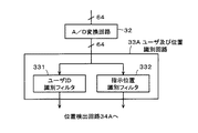
図3は、ユーザ及び位置識別回路33Aの構成例を説明するためのブロック図である。図3に示すように、ユーザ及び位置識別回路33Aは、各受信導体に対して、ユーザID識別フィルタ331と、指示位置識別フィルタ332とが設けられたものである。そして、ユーザID識別フィルタ331がマルチユーザの検出を実現する部分であり、指示位置識別フィルタ332がマルチタッチの検出を実現する部分である。
FIG. 3 is a block diagram for explaining a configuration example of the user and
ユーザID識別フィルタ331は、A/D変換回路32を通じて供給される各受信導体からのデジタル化された受信信号のそれぞれに対して、各ユーザが備える信号発生器2からの信号と同じ周波数の信号を用いて同期検波演算を行う。これによって、指示操作を行ったユーザがあるときには、指示体を用いて指示操作を行ったユーザを、ユーザID識別フィルタ331を介して、受信導体毎に識別(検出)することができる。
For each digitized reception signal from each reception conductor supplied through the A /
具体的には、ユーザID識別フィルタ331は、受信導体毎に、DCT演算を用いた同期検波処理を行う演算回路が、同時に操作が可能とされるユーザの数だけ並列に設けられる。各演算回路には、ユーザ毎に周波数が異なるようにされる信号発生器2で発生させる信号と同じ周波数の信号が1対1に対応するように割り当てられる。 Specifically, as many user ID identification filters 331 as the number of users that can be operated simultaneously are provided in parallel for each reception conductor, with arithmetic circuits that perform synchronous detection processing using DCT arithmetic. Each arithmetic circuit is assigned a signal having the same frequency as the signal generated by the signal generator 2 whose frequency is different for each user in a one-to-one correspondence.
そして、ユーザID識別フィルタ331に並列に設けられる各演算回路のそれぞれでは、デジタル信号に変換された所定の受信導体からの信号に対して、自らの回路に割り当てられた所定の周波数の信号を乗算して積分する。この場合に、各演算回路のそれぞれは、例えば、当該所定の周波数の信号が存在する場合にはハイレベルとなり、存在しない場合にはローレベルとなる信号を出力する。これにより、各演算回路において自らの回路に割り当てられた周波数の信号が検出できた場合には、処理対象の信号の供給元の受信導体に対して、その周波数の信号を発生させている信号発生器2を用いているユーザが指示体を用いて指示入力を行っていると判別できる。
Each of the arithmetic circuits provided in parallel with the user
このように、この実施の形態において、ユーザが備える信号発生器2からの信号の周波数がユーザを識別するためのID情報になっている。そして、ユーザID識別フィルタ331は、上述したように、どの受信導体に対して、どのユーザが指示体を用いて指示入力を行っているのかを示す情報を出力することができるようにされている。
Thus, in this embodiment, the frequency of the signal from the signal generator 2 included in the user is ID information for identifying the user. As described above, the user
一方、指示位置識別フィルタ332は、A/D変換回路32を通じて供給される各受信導体からのデジタル化された受信信号のそれぞれに対して、送信導体群11の各送信導体に供給された信号と同じ周波数の信号を用いた同期検波演算を行う。これにより、指示位置識別フィルタ332は、各クロスポイントにおける電流変化を検出する。なお、この電流変化は電圧の変化に変換して検出することもできる。
On the other hand, the indication
具体的には、指示位置識別フィルタ332は、受信導体毎に、DCT演算を用いた同期検波処理を行う演算回路が、送信導体の数と同じ64個設けられる。そして、受信導体毎に設けられる各演算回路には、送信導体毎に周波数が異なるようにされる各送信導体に供給された信号と同じ周波数の信号が1対1に対応するように割り当てられる。
Specifically, the indication
このように、指示位置識別フィルタ332には、64本の受信導体毎に、64本の送信導体に対応して64個の演算回路が設けられる。換言すれば、指示位置識別フィルタ332に設けられる各演算回路は、指示入力面100S上の64個×64個のクロスポイントに対応するように、設けられている。
As described above, the indication
そして、指示位置識別フィルタ332において、受信導体毎に設けられる64個の演算回路のそれぞれにおいては、対応する受信導体からのデジタル信号とされた信号に対して、自らの回路に割り当てられた所定の周波数の信号を乗算して積分する。これにより、受信導体毎に設けられる64個の演算回路のそれぞれにおいて、受信信号の供給元の受信導体と、各送信導体とが形成するクロスポイントにおける電流変化が検出される。
In the pointing
上述したように、送信導体群11の各送信導体には、送信信号供給回路21により、送信導体毎に異なる周波数の信号が供給されている。したがって、指示体であるユーザの指がセンサ部100の指示入力面100Sに接触または近接すると、近隣のクロスポイントでは送信導体からの送信信号が指示体へも流れこみ、送信導体から受信導体へ流れ込む電流が減少する。
As described above, a signal having a different frequency for each transmission conductor is supplied to each transmission conductor of the
このため、指示位置識別フィルタ332において、各クロスポイントに対応して設けられる演算回路は、対応するクロスポイントに指示体が接触あるいは近接している場合には、指示体が接触も近接もしていない通常レベルよりも低いレベルの検出信号を出力する。これにより、指示位置識別フィルタ332の各演算回路からの検出出力に基づいて、指示体が接触あるいは近接しているクロスポイントを識別(検出)することができる。そして、クロスポイントは、上述したように、受信導体と送信導体との交差点であるので、指示入力面100S上における指示体の接触位置または近接位置を、指示入力面100S上のクロスポイントにおいて把握することができる。
For this reason, in the indication
このように、指示位置識別フィルタ332は、指示入力面100S上のどのクロスポイントに対して指示体により指示操作が行われているのかを示す情報を出力することができるようにされる。
As described above, the indication
そして、受信部300Aの位置検出回路34Aは、ユーザID識別フィルタ331からの、どの受信導体に対してどのユーザが指示体を用いて指示入力を行っているのかを示す情報の提供を受ける。また、位置検出回路34Aは、指示位置識別フィルタ332から、指示入力面100S上のどのクロスポイントに対して指示体により指示操作が行われているのかを示す情報の提供を受ける。
The
位置検出回路34Aは、ユーザID識別フィルタ331からの情報と指示位置識別フィルタ332からの情報とに基づいて、1以上の指示体による指示位置のそれぞれを検出すると共に、各指示位置は、どのユーザによって指示されたかを検出して出力する。すなわち、位置検出回路34Aは、指示入力面100S上の指示体による指示位置を示す2次元座標データ(X軸データとY軸データ)と、ユーザ識別情報とが対応付けられた情報を出力する。
The
具体的には、例えば、図2に示したように、センサ部100上の受信導体12X6と送信導体11Y61とが交差するクロスポイントに、ユーザAが指(指示体)を接触させていたとする。この場合、上述した指示位置識別フィルタ332の機能により、受信導体12X6と送信導体11Y61とが交差するクロスポイントが指示体により指示されていることが識別される。同時に、上述したユーザID識別フィルタ331の機能により、受信導体12X6をユーザAが指示体により指示していることが識別される。これらの識別結果は受信導体12Xにより対応付け(紐付け)することができる。
Specifically, for example, as illustrated in FIG. 2, the user A is in contact with a finger (indicator) at a cross point where the receiving
したがって、この例の場合、位置検出回路34Aは、指示体の指示位置を示す2次元座標データ(受信導体12X6、送信導体11Y61)と、ユーザ識別情報(ユーザAのユーザID)とを対応付けた、例えば、(受信導体12X6、送信導体11Y61、ユーザA)という情報を形成して出力する。そして、複数のユーザが、両方の手の5本の指の全てを指示体として用いて、センサ部100に対して指示操作を行っても、ユーザ及び位置識別回路33Aの機能により、指示体毎に、その指示位置(クロスポイント)と、その指示体を使用したユーザとを把握することができる。このため、位置検出回路34Aは、指示体毎に、指示体の指示位置を示す2次元座標データと、ユーザ識別情報とを対応付けた情報を形成して出力することができる。また、ユーザBの指がセンサ部100上の位置を指示していた場合にも、同様にして、指示体の指示位置を示す2次元座標データと、ユーザ識別情報とを対応付けた情報を出力することができる。
Therefore, in this example, the
位置検出回路34Aからの出力情報は、図1に示した表示制御装置4に供給される。これにより、表示制御装置4は、以下に具体的に説明するように、ユーザ毎の指示位置に応じた、ディスプレイ装置3の表示画面上の対応する位置に、各ユーザを識別可能な態様で情報を表示するなどのことができるようにされる。
Output information from the
[マルチタッチ・マルチユーザ検出装置1を有する情報処理装置の利用態様]
次に、この実施の形態のマルチタッチ・マルチユーザ検出装置1が用いられて形成された図1に示した情報処理装置の利用態様について具体的に説明する。
[Usage Mode of Information Processing Device Having Multi-Touch / Multi-User Detection Device 1]
Next, a usage mode of the information processing apparatus shown in FIG. 1 formed by using the multi-touch /
図4は、この実施の形態のマルチタッチ・マルチユーザ検出装置1が用いられて形成された情報処理装置の利用態様の一例を説明するための図であり、マルチタッチ・マルチユーザ検出装置1の指示入力面(操作面)100Sの上方から見た場合を示している。図4に示した例においては、ユーザA、Bは、マルチタッチ・マルチユーザ検出装置1の指示入力面100Sを挟んで、斜めに向かい合うように位置している。
FIG. 4 is a diagram for explaining an example of a usage mode of the information processing apparatus formed by using the multi-touch /
そして、図4に示すように、ユーザA、Bのそれぞれが、所定の四角形の対角線上の2点を指示するように、指示入力面100Sに対して自己の両手を接触あるいは近接させるようにしたとする。マルチタッチ・マルチユーザ検出装置1は、上述したように、マルチタッチの検出とマルチユーザの検出とを行って、その検出出力を表示制御装置4に対して供給する。
Then, as shown in FIG. 4, each of the users A and B touches or approaches their own hands to the instruction input surface 100 </ b> S so as to indicate two points on a predetermined rectangular diagonal line. And As described above, the multi-touch /
このように、指示入力面100Sに対して、ユーザが対角線上の2点を同時に指示する操作が行われた場合には、表示制御装置4は、ユーザ操作領域の設定指示が行われたと判別する。そして、表示制御装置4は、指示された2点を結ぶ直線を対角線とする四角形の領域をユーザ操作領域として設定する。そして、表示制御装置4は、指示された領域部分に対応するディスプレイ装置3の表示画面上の領域部分に枠線を表示したり、表示画面上の当該領域部分を反転表示したりすることにより、ユーザにより指示されたユーザ操作領域を認識できるようにする。 As described above, when the user performs an operation for simultaneously instructing two points on the diagonal line on the instruction input surface 100 </ b> S, the display control device 4 determines that the user operation area setting instruction has been performed. . Then, the display control device 4 sets a quadrangular area whose diagonal is a straight line connecting the instructed two points as a user operation area. Then, the display control device 4 displays a frame line in the region portion on the display screen of the display device 3 corresponding to the designated region portion, or reversely displays the region portion on the display screen, thereby The user operation area designated by the user can be recognized.
図4に示した例の場合には、マルチタッチ・マルチユーザ検出装置1の指示入力面100Sの左側にユーザAが指定したユーザ操作領域ArAが設定され、指示入力面100Sの右側にユーザBが指定したユーザ操作領域ArBが設定された場合を示している。そして、ユーザ操作領域に対しては、ユーザが指示体を用いて直接に文字、記号、絵、図形などを描くようにすることにより、表示制御装置4が当該入力情報を認識する。そして、表示制御装置4は、認識した入力情報を入力操作が行われた当該ユーザ操作領域に一致するディスプレイ装置3の表示画面の表示領域に表示することができる。
In the case of the example shown in FIG. 4, the user operation region ArA user A specifies the left side of the pointing
また、情報の別の入力方法として、いわゆるソフトウェアキーボードなどの表示情報を通じて行う方法がある。具体的には、表示制御装置4の制御により、ユーザ操作領域に対して、数字キー、アルファベットキー(50音文字キー)、記号キー等からなるソフトウェアキーボードを表示し、当該ソフトウェアキーボードに対して、ユーザが指示体を通じて指示操作を行う。そして、表示制御装置4が、ユーザが指示した位置に対応するソフトウェアキーボードの表示情報を認識することにより、ユーザによって指示された文字等の情報の入力を受け付けることができるようにされる。この場合にも、表示制御装置4は、認識した入力情報を入力操作が行われた当該ユーザ操作領域に一致するディスプレイ装置3の表示画面の表示領域の所定の位置に表示することができる。 As another method for inputting information, there is a method using display information such as a so-called software keyboard. Specifically, under the control of the display control device 4, a software keyboard composed of numeric keys, alphabet keys (50-character keys), symbol keys, etc. is displayed for the user operation area. The user performs an instruction operation through the indicator. Then, the display control device 4 recognizes the display information of the software keyboard corresponding to the position instructed by the user, so that the input of information such as characters instructed by the user can be accepted. Also in this case, the display control device 4 can display the recognized input information at a predetermined position in the display area of the display screen of the display device 3 that matches the user operation area where the input operation has been performed.
そして、表示制御装置4は、マルチタッチ・マルチユーザ検出装置1からの検出出力に基づいて、ユーザ操作領域ArAはユーザAにより設定され、ユーザ操作領域ArBはユーザBにより設定されたことを認識し、これを管理することができる。このため、ユーザ操作領域ArAに対しては、ユーザAからの操作入力を有効にし、ユーザ操作領域ArBに対しては、ユーザBからの操作入力を有効にする。
Then, the display control device 4 recognizes that the user operation area ArA is set by the user A and the user operation area ArB is set by the user B based on the detection output from the multi-touch /
そして、表示制御装置4は、各ユーザ操作領域に対して入力された情報を、自機に内蔵する半導体メモリやハードディスクなどの記録媒体や自機に接続される記録装置の記録媒体に、ユーザ毎(ユーザ操作領域毎)にファイルを分けて記録し、保持することができる。例えば、ユーザ操作領域ArAに対して入力された情報はファイルAに記録し、ユーザ操作領域ArBに対して入力された情報はファイルBに記録するといったことができる。 Then, the display control device 4 stores the information input to each user operation area on a recording medium such as a semiconductor memory or a hard disk built in the own device or a recording medium of a recording device connected to the own device. Files can be recorded and stored separately for each user operation area. For example, information input to the user operation area ArA can be recorded in the file A, and information input to the user operation area ArB can be recorded in the file B.
また、ユーザは自己のユーザ操作領域の対角線上の2点を、両手を用いて指示し、狭めたり、広げたりする操作を行うことによって、ユーザ操作領域の大きさを調整することができる。また、ユーザは、自己のユーザ操作領域内に指を接触させて、その指の接触状態を維持したまま指を引きずるようにするいわゆるドラッグ操作を行うことによって、指示入力面100S上において当該ユーザ操作領域の形成位置を移動させることもできる。この場合、ディスプレイ装置3の表示画面上の表示領域もユーザ操作領域の移動に対応して移動する。したがって、ユーザ操作領域と対応する表示領域とがずれることはない。
In addition, the user can adjust the size of the user operation area by instructing two points on the diagonal line of his / her user operation area using both hands and performing an operation of narrowing or widening. In addition, the user performs a so-called drag operation in which the finger is brought into contact with the user operation area and the finger is dragged while maintaining the contact state of the finger, thereby performing the user operation on the
また、ユーザ操作領域に入力された情報を、他のユーザ操作領域にコピーすることもできる。図5は、ユーザ操作領域間の入力情報のコピー処理を説明するための図である。図5(A)に示すように、指示入力面100S上に、ユーザAが形成するようにしたユーザ操作領域ArAと、ユーザBが形成するようにしたユーザ操作領域ArBとが設けられているとする。そして、ユーザ操作領域ArBには、ユーザBによって情報「○○△○○」が入力されて、これがディスプレイ装置3の表示画面上のユーザ操作領域ArBに対応する表示領域に表示されているとする。
In addition, information input to the user operation area can be copied to another user operation area. FIG. 5 is a diagram for explaining a process of copying input information between user operation areas. As shown in FIG. 5A, a user operation area ArA formed by the user A and a user operation area ArB formed by the user B are provided on the
そして、ユーザ操作領域ArBに表示されている情報「○○△○○」を、ユーザ操作領域ArAにコピーする必要が生じたとする。この場合には、ユーザ操作領域ArBに、例えばユーザBが指を接触させてドラック操作を行うことにより、図5(B)に示すように、ユーザ操作領域ArBの指示入力面100S上の形成位置を変更させる。そして、ユーザ操作領域ArAの一部に、ユーザ操作領域ArBの一部を重ね合わせるようにする。
Then, it is assumed that it is necessary to copy the information “◯◯ △ ◯◯” displayed in the user operation area ArB to the user operation area ArA. In this case, when the user B touches the user operation area ArB, for example, and performs a drag operation, the formation position on the
このように、ユーザによる指示操作によって、ユーザ操作領域ArAの一部に、ユーザ操作領域ArBの一部が重ね合わせるようにされた場合に、表示制御装置4は、ユーザ操作領域ArBからユーザ表示領域ArAへの情報のコピーが指示されたと判別する。そして、表示制御装置4は、図5(B)に示すように、ユーザ操作領域ArBに表示されている情報「○○△○○」を、ユーザBが指示体によってユーザ操作領域ArAに移動操作することで、ユーザ操作領域ArAに対応する表示領域にも表示させる。これにより、ユーザ操作領域ArBに表示されている情報は、ユーザ操作領域ArAにコピーされる。 As described above, when a part of the user operation area ArB is overlapped with a part of the user operation area ArA by an instruction operation by the user, the display control device 4 changes from the user operation area ArB to the user display area. It is determined that copying of information to ArA is instructed. Then, as shown in FIG. 5B, the display control device 4 moves the information “◯◯ △ ◯◯” displayed in the user operation area ArB to the user operation area ArA by the indicator. By doing so, it is also displayed in the display area corresponding to the user operation area ArA. Thereby, the information displayed in the user operation area ArB is copied to the user operation area ArA.
なお、ユーザ操作領域には、種々の情報が多数入力されて、これらが対応する表示領域に表示されている場合に、その中の一部の情報だけを他のユーザ操作領域にコピーするようにしたい場合もある。このような場合には、まず、ユーザが、自己のユーザ操作領域において、コピーしたい情報が表示されている表示領域上の部分を、指等を用いてドラックするなどして、コピー対象の情報を指定する。 In addition, when a lot of various information is input to the user operation area and displayed in the corresponding display area, only a part of the information is copied to the other user operation area. Sometimes you want to. In such a case, first, the user drags the part on the display area where the information to be copied is displayed in his / her user operation area by using a finger or the like, so that the information to be copied is displayed. specify.
この後、上述したように、例えばユーザBが指を接触させてドラック操作を行うことにより、図5(B)に示したように、コピー元のユーザ操作領域の表示位置を移動させ、コピー先のユーザ操作領域の一部に、コピー元のユーザ操作領域の一部を重ね合わせるようにする。これにより、コピー元のユーザ操作領域の指示した部分の情報を、コピー先のユーザ操作領域にコピーすることができる。 Thereafter, as described above, for example, when the user B performs a drag operation by touching the finger, the display position of the copy source user operation area is moved as shown in FIG. A part of the copy source user operation area is superimposed on a part of the user operation area. As a result, it is possible to copy the information of the designated part of the copy source user operation area to the copy destination user operation area.
なお、情報のコピーだけでなく、コピーの場合と同様にして情報の移動を行うこともできる。この場合には、コピーしたい情報や移動したい情報を指定した後に、アイコンなどを通じてコピーするか移動するかを選択できるようにしておけばよい。そして、移動することが選択された場合には、移動元の表示領域から該当情報が消去され、移動先の表示領域に該当情報が表示するようにされることになる。 Note that not only information copying but also information movement can be performed in the same manner as copying. In this case, after specifying the information to be copied or the information to be moved, it may be possible to select whether to copy or move through an icon or the like. When moving is selected, the corresponding information is erased from the display area of the movement source, and the corresponding information is displayed in the display area of the movement destination.
また、別の操作により入力情報のコピーや移動を行うようにすることもできる。例えば、コピー元や移動元のユーザ操作領域に対応する表示領域に表示されている情報の内、コピーや移動の対象となる情報を、その表示位置をなぞる(ドラッグ操作)するなどして指定する。この後、当該情報の指定を行ったユーザが、コピー先や移動先のユーザ操作領域の目的とする位置に指等を接触させ、コピー位置や移動位置を指示することにより、情報のコピーや移動を行うようにすることもできる。 Also, the input information can be copied or moved by another operation. For example, the information to be copied or moved among the information displayed in the display area corresponding to the copy-source or move-source user operation area is specified by tracing the display position (drag operation) or the like. . Thereafter, the user who has designated the information touches the target position in the user operation area of the copy destination or the move destination, and designates the copy position or the move position, thereby copying or moving the information. It is also possible to perform.
この他、ユーザ領域内において、コピーや移動を行う情報を選択した後、コピー位置や移動位置を指示する操作を行うことにより、ユーザ領域内における情報のコピーや移動を行うこともできる。ユーザ領域内において、削除する情報を選択した後、所定の削除の実行を指示する操作を行うことにより、ユーザ領域内における情報の削除を行うこともできる。もちろん、目的とする情報を変更したり、目的とする位置に情報を追加したりすることもできる。このように、各ユーザは、マルチタッチ・マルチユーザ検出装置1の指示入力面100Sに対して、種々の指示操作を行うことにより、目的とする種々の処理を行うようにすることができる。
In addition, after selecting information to be copied or moved in the user area, the user can copy or move the information in the user area by performing an operation for instructing the copy position or the moving position. It is also possible to delete information in the user area by selecting the information to be deleted in the user area and then performing an operation to instruct execution of predetermined deletion. Of course, the target information can be changed, or information can be added to the target position. In this way, each user can perform various target processes by performing various instruction operations on the instruction input surface 100 </ b> S of the multi-touch /
ところで、図4に示したように、複数のユーザのユーザ操作領域のそれぞれが、他のユーザのユーザ操作領域と重複することなく設定される場合、各ユーザは自分のユーザ操作領域を適切に認識し、指示入力面100S上の自分の指示位置をも的確に認識できる。しかし、複数のユーザの指示位置が入り組む場合もある。このような場合であっても、この実施の形態のマルチタッチ・マルチユーザ検出装置1を用いた情報処理装置においては、各ユーザの指示位置を明確に示すことができるようにしている。
By the way, as shown in FIG. 4, when each of the user operation areas of a plurality of users is set without overlapping with the user operation areas of other users, each user appropriately recognizes his / her user operation area. In addition, the user's designated position on the
図6は、ユーザA、Bのマルチタッチ・マルチユーザ検出装置1の指示入力面100Sに対する指示位置が入り組むために、それぞれのユーザ操作領域の一部が重複するようにされた場合について説明するための図である。図6に示すように、ユーザA、Bのそれぞれが、マルチタッチ・マルチユーザ検出装置1の指示入力面100S上において、両手を用いて対角線上の2点を指示し自己のユーザ操作領域を設定する操作を行うようにしたとする。
FIG. 6 illustrates a case where the user A and B have a plurality of pointing positions with respect to the pointing
この場合に、図6に示すように、ユーザA、Bのそれぞれの右手が、指示入力面100S上の近接する位置を指示した場合、ユーザA、Bのそれぞれが、自己の右手の指示位置を見間違うなどといった不都合を生じさせる場合があると考えられる。このような不都合は、マルチタッチ・マルチユーザ検出装置1に対して同時に操作を行うユーザが多くなることによって、発生する可能性が高くなる。
In this case, as shown in FIG. 6, when the right hands of the users A and B indicate the positions close to each other on the instruction input surface 100 </ b> S, the users A and B respectively indicate their right hand pointing positions. It is thought that inconveniences such as mistakes may occur. Such inconvenience increases as the number of users who simultaneously operate the multi-touch /
そこで、この実施の形態のマルチタッチ・マルチユーザ検出装置1を用いた情報処理装置では、ユーザ毎の指示位置を、ユーザ毎に異なるマーク(タッチマーク)を用いて表示することによって、ユーザの指示位置の誤認識を防止するようにしている。この実施の形態のマルチタッチ・マルチユーザ検出装置1は、上述したように、指示入力面100S上の指示位置と、各指示位置はどのユーザによって指示されたかを検出し、表示制御装置4に通知することができる。
Therefore, in the information processing apparatus using the multi-touch /
そこで、表示制御装置4は、指示入力面100S上の指示位置に対応するディスプレイ装置3の表示画面上の位置に、ユーザ毎に異なる態様のマーク(タッチマーク)を表示することにより、各ユーザの指示位置を、互いに識別可能に、明確に示すことができるようにしている。図6に示した例においては、ユーザAの指示位置に対応するディスプレイ装置3の表示画面上の位置には、四角形のタッチマークMAを表示するようにしている。また、図6に示した例においては、ユーザBの指示位置に対応するディスプレイ装置3の表示画面上の位置には、円形のタッチマークMBを表示するようにしている。
Therefore, the display control device 4 displays a mark (touch mark) of a different mode for each user at a position on the display screen of the display device 3 corresponding to the indication position on the
これにより、各ユーザは、指示体として用いた自分の指の指示位置に表示されるタッチマークMA、MBによって、自分の指による指示位置を明確に認識することができるようにされる。なお、ここでは、指示体による指示位置をユーザ毎に形の異なるタッチマークを用いて示すようにしたが、これに限るものではない。指示体による指示位置をユーザ毎に異なる色の表示により示すようにしてもよい。この場合、色を異ならせる部分の形状は、ユーザ毎に異なるようにしてもよいし、共通の形状とするようにしてもよい。 Thus, each user can clearly recognize the designated position by his / her finger by the touch marks MA and MB displayed at the designated position of his / her finger used as the indicator. Here, the indication position by the indicator is indicated by using touch marks having different shapes for each user, but the present invention is not limited to this. You may make it show the indication position by a pointer by the display of a different color for every user. In this case, the shape of the portion that changes the color may be different for each user, or may be a common shape.
また、図6において、ユーザA、Bのそれぞれの掌を囲むように円形で示された部分(各ユーザの手の複数の指によって指示された部分)をユーザ毎に異なる色によって示すようにしてもよい。当該部分は、ユーザ毎に異なる形状としてもよいし、共通の形状としてもよい。このように、指示体による指示位置をユーザ毎に異なる態様で示すことにより、ユーザ毎の指示位置を明確に示すことができる。 Further, in FIG. 6, a portion (a portion indicated by a plurality of fingers of each user's hand) shown in a circle so as to surround each palm of the users A and B is indicated by a different color for each user. Also good. The said part is good also as a different shape for every user, and is good also as a common shape. Thus, the indication position for each user can be clearly shown by indicating the indication position by the indicator in a different manner for each user.
また、図6に示した例の場合には、ユーザAによりユーザ操作領域ArAが形成するようにされ、ユーザBによりユーザ操作領域ArBが形成するようにされた場合を示している。そして、このユーザ操作領域についても、どの領域がどのユーザの領域かを明確にするために、ユーザ操作領域ArAを囲むように表示される枠線とユーザ操作領域ArBを囲むように表示される枠線とで、表示色や枠線の種類を変えるようにすることもできる。 In the case of the example shown in FIG. 6, the user operation area ArA is formed by the user A, and the user operation area ArB is formed by the user B. Also, for this user operation area, in order to clarify which area is which user's area, a frame line displayed so as to surround the user operation area ArA and a frame displayed so as to surround the user operation area ArB It is also possible to change the display color and the type of the frame line.
また、ユーザ操作領域ArAとユーザ操作領域ArBとで、背景色を異ならせるようにすることもできる。例えば、ユーザ操作領域ArAの背景色を白色とし、ユーザ操作領域ArBの背景色を黒色とし、両領域が重なり合う部分を灰色とすることにより、各ユーザ操作領域を明確に示すことができると共に、両領域が重複する部分についても明確に示すことができる。 Also, the user operation area ArA and the user operation area ArB can have different background colors. For example, by setting the background color of the user operation area ArA to white, the background color of the user operation area ArB to black, and the portion where both areas overlap to be gray, each user operation area can be clearly shown, It is possible to clearly show the overlapping area.
また、指示入力面100Sを通じて入力された情報を、ユーザ毎に異なる色で表示するようにしたり、ユーザ毎に反転表示と非反転表示とを異ならせるようにしたりするなど、種々の異なる態様で表示することもできる。また、指示入力面100S上の指示位置の軌跡をユーザ毎に異なる色で表示したり、軌跡を示す線種を異なるようにしたりするなど、種々の異なる態様で表示することもできる。
In addition, the information input through the
[マルチタッチ・マルチユーザ検出装置1を用いた情報処理装置の他の例]
図1に示したように、上述した実施の形態の情報処理装置は、マルチタッチ・マルチユーザ検出装置1をディスプレイ装置3の表示画面上に積層して一体に形成したものである。しかし、マルチタッチ・マルチユーザ検出装置とディスプレイ装置とを別体とした情報処理装置を構成することもできる。
[Another example of the information processing apparatus using the multi-touch / multi-user detection apparatus 1]
As shown in FIG. 1, the information processing apparatus according to the embodiment described above is formed by integrally stacking a multi-touch /
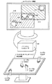
図7は、マルチタッチ・マルチユーザ検出装置とディスプレイ装置とを別体とした情報処理装置の例を説明するための図である。図7に示すように、この例の情報処理装置は、マルチタッチ・マルチユーザ検出装置1と、パーソナルコンピュータ4Aと、ディスプレイ装置3Aとが、それぞれ別体のものとして設けられたものである。
FIG. 7 is a diagram for explaining an example of an information processing device in which a multi-touch / multi-user detection device and a display device are separated. As shown in FIG. 7, the information processing apparatus of this example is provided with a multi-touch /
図7において、マルチタッチ・マルチユーザ検出装置1は、図2、図3を用いて説明したものと同様に構成されたものである。しかし、図7に示した例の場合には、マルチタッチ・マルチユーザ検出装置1とディスプレイ装置とは別体である。このため、マルチタッチ・マルチユーザ検出装置1のセンサ部100は透過性を有する必要はない。
In FIG. 7, the multi-touch /
また、図7において、パーソナルコンピュータ4Aは、図1に示した情報処理装置における表示制御装置4と同様の機能を実現するものである。すなわち、パーソナルコンピュータ4Aは、マルチタッチ・マルチユーザ検出装置1からの検出出力に応じて、ディスプレイ装置3Aの表示画面に種々の情報を表示することができるものである。また、図7において、ディスプレイ装置3Aは、LCD、有機ELディスプレイ、PDPなどの薄型の表示素子やCRTが適用し得る。
In FIG. 7, the personal computer 4A realizes the same function as the display control device 4 in the information processing apparatus shown in FIG. That is, the personal computer 4 </ b> A can display various information on the display screen of the display device 3 </ b> A according to the detection output from the multi-touch /
そして、図7に示した例の場合にも、マルチタッチ・マルチユーザ検出装置1は、1以上の指示体による指示位置のそれぞれを検出すると共に、各指示位置は、どのユーザによって指示されたかを検出して、パーソナルコンピュータ4Aに通知する。具体的に、マルチタッチ・マルチユーザ検出装置1は、指示入力面100S上の指示体による指示位置を示す2次元座標データ(X軸データとY軸データ)と、ユーザ識別情報とを対応付けた情報をパーソナルコンピュータ4Aに供給する。
In the case of the example shown in FIG. 7, the multi-touch /
パーソナルコンピュータ4Aは、マルチタッチ・マルチユーザ検出装置1からの検出出力に応じて、指示体による指示位置に対応するディスプレイ装置3Aの表示画面上の位置に、ユーザ毎に異なる態様の表示を行うなどのことができるようにされる。図7に示した例では、図6の場合と同様に、ユーザAによる指示位置を四角形のタッチマークMAにより示し、ユーザBによる指示位置を、円形のタッチマークMBにより示している。
In response to the detection output from the multi-touch /
また、図7において、ユーザAが指を指示体として用いて指示した部分を四角形の表示を用いて示したり、ユーザBが指を指示体として用いて指示した部分を円形の表示を用いて示したりすることもできるようにされる。これらの部分にユーザ毎に異なる色を付すようにすることもできる。また、ユーザAが設定するようにしたユーザ操作領域ArAとユーザBが設定するようにしたユーザ操作領域ArBとの区別についても、図6を用いて説明した場合と同様に、枠線や背景色を異ならせるようにして、明確に示すようにすることもできる。 Further, in FIG. 7, a portion indicated by user A using a finger as an indicator is shown using a square display, and a portion indicated by user B using a finger as an indicator is shown using a circular display. You can also do. It is also possible to add different colors to these portions for each user. As for the distinction between user operation region ArB a user operation region ArA and the user B that the user A has to be set has to be set, similarly to the case described with reference to FIG. 6, borders, background color It is also possible to make them clearly shown by making them different.
この他、図7に示したように、各装置が別体とされた情報処理装置の場合であっても、図1に示した一体型の情報処理装置の場合と同様に、ユーザからの指示操作を受け付けて、これに応じた表示制御処理を行うことができる。そして、図7に示した別体型の情報処理装置の場合には、ユーザの手などの指示体が、ディスプレイ装置3Aの表示画面上に位置することはない。このため、図7に示した別体型の情報処理装置の場合には、マルチタッチ・マルチユーザ検出装置1に対して指示操作を行いながら、ディスプレイ装置3Aの表示画面の全体を確認できる。
In addition, as shown in FIG. 7, even if each device is a separate information processing device, as in the case of the integrated information processing device shown in FIG. It is possible to receive an operation and perform display control processing corresponding to the operation. In the case of the separate information processing apparatus shown in FIG. 7, an indicator such as a user's hand is not positioned on the display screen of the display device 3A. For this reason, in the case of the separate information processing apparatus shown in FIG. 7, the entire display screen of the display apparatus 3 </ b> A can be confirmed while performing an instruction operation on the multi-touch /
[マルチタッチ・マルチユーザ検出装置1の構成の変形例]
マルチタッチ・マルチユーザ検出装置1は、図2、図3を用いて説明したように、受信部300Aのユーザ及び位置識別回路33Aにおいて、マルチユーザの検出(識別)とマルチタッチの検出(識別)とを行うようにした。しかし、これに限るものではない。例えば、受信導体群12の各受信導体からの信号に基づいてマルチユーザの検出を行う回路部分を、受信部300Aに設けない構成とすることもできる。また、送信導体群11の各送信導体からの信号に基づいてマルチユーザの検出を行う回路部分を設けるようにすることもできる。
[Modification of Configuration of Multi-Touch / Multi-User Detection Device 1]
As described with reference to FIGS. 2 and 3, the multi-touch /
図8は、マルチユーザの検出を行う回路部分を設ける箇所についての変形例を説明するためのブロック図である。図8において、センサ部100及び送信部200は、図2を用いて説明したものと同様に構成された部分である。また、受信部300は、図11を用いて説明したように、従来のクロスポイント型静電結合方式の指示体検出装置の場合と同様に、マルチタッチの検出(多点検出)のみを行う部分として構成された部分であり、図11に示したように、増幅回路31、A/D変換回路32、演算処理回路33、位置検出回路34からなる部分である。なお、演算処理回路33は、図3に示した指示位置識別フィルタ332と同様に構成されるものである。
FIG. 8 is a block diagram for explaining a modified example of a place where a circuit portion for performing multi-user detection is provided. In FIG. 8, the sensor unit 100 and the
そして、X軸方向ユーザID検出部400が、受信部300に対して並列に設けられるようにされた、受信導体群12の各受信導体からの信号に基づいてマルチユーザの検出を行う回路部分である。具体的に、X軸方向ユーザID検出部400は、図示しないが、増幅回路と、A/D変換回路と、ユーザID識別フィルタと、ユーザ検出回路とからなる部分である。
The X-axis direction user
ここで、X軸方向ユーザID検出部400の増幅回路は、受信部300の増幅回路31と同様に構成された部分であり、X軸方向ユーザID検出部400のA/D変換回路は、受信部300のA/D変換回路32と同様に構成された部分である。また、X軸方向ユーザID検出部400のユーザID識別フィルタは、図2を用いて説明したユーザID識別フィルタと同様に構成された部分である。また、X軸方向ユーザID検出部400のユーザ検出回路は、ユーザID識別フィルタからの検出出力に基づいて、どの受信導体に対してどのユーザが指示を行っているかを示す情報を出力し、表示制御装置に供給するようにするものである。
Here, the amplification circuit of the X-axis direction user
このようにすれば、センサ部100と、送信部200と、受信部300とからなる従来のクロスポイント型静電結合方式の指示体検出装置に対して、X軸方向ユーザID検出部400を設けることにより、この発明のマルチタッチ・マルチユーザ検出装置1を実現することができる。
In this way, the X-axis direction user
また、マルチユーザの検出を、送信導体群11を構成する送信導体を通じて行うようにすることもできる。すなわち、マルチユーザの検出は、各ユーザの指示体を通じてセンサ部100に供給される各ユーザが備える信号発生器2からの信号を検出することにより行うことができる。このため、送信導体群11を構成する各送信導体に供給される各ユーザの信号発生器2からの信号を検出することにより、マルチユーザの検出を行うことができる。
Further, multi-user detection can be performed through the transmission conductors constituting the
そこで、図8に示すように、送信導体群11を構成する各送信導体からの信号の供給を受けるY軸方向ユーザID検出部500を設け、ここでマルチユーザの検出を行うようにする。このY軸方向ユーザID検出部500の具体的な構成は、入力信号が異なるだけで、基本的には、X軸方向ユーザID検出部400と同様に構成することができる。すなわち、Y軸方向ユーザID検出部500は、図示しないが、増幅回路と、A/D変換回路と、ユーザID識別フィルタと、ユーザ検出回路とからなる。
Therefore, as shown in FIG. 8, a Y-axis direction user
そして、Y軸方向ユーザID検出部500の増幅回路もまた、受信部300の増幅回路31と同様に構成される部分であり、Y軸方向ユーザID検出部500のA/D変換回路は、受信部300のA/D変換回路32と同様に構成される部分である。また、Y軸方向ユーザID検出部500のユーザID識別フィルタもまた、図2を用いて説明したユーザID識別フィルタと同様に構成される部分である。そして、Y軸方向ユーザID検出部500のユーザ検出回路は、ユーザID識別フィルタからの検出出力に基づいて、どの送信導体に対してどのユーザが指示を行っているかを示す情報を出力し、表示制御装置に供給するようにするものである。
The amplification circuit of the Y-axis direction user
このような構成のY軸方向ユーザID検出部500を備えることにより、送信導体群11を構成するどの送信導体に対して、どのユーザが指示体を用いて指示操作を行っているのかを検出することができる。そして、マルチタッチの検出は、受信部300において行うことができるので、受信部300の検出出力と、Y軸方向ユーザID検出部500の検出出力に基づいて、各指示位置は、どのユーザによる指示かを把握することができるようにされる。
By including the Y-axis direction user
なお、上述したように、送信導体群11を構成する各送信導体に対しては、マルチタッチの検出(多点検出)を実現するために、送信導体毎に異なる周波数の信号(多周波信号)が供給される。このため、多周波信号が供給されている各送信導体から、各ユーザの信号発生器2から供給される信号を検出することは難しい。
As described above, with respect to each transmission conductor constituting the
そこで、送信導体群11の各送信導体に供給する多周波信号の周波数帯域と、各ユーザの信号発生器2が発生させる信号の周波数帯域とをある程度はなれた帯域となるようにする。そして、Y軸方向ユーザID検出部500の前段に、各送信導体から各ユーザの信号発生器2が発生させる信号の周波数帯域の信号を通過させる帯域フィルタを設けることにより、各送信導体に供給される多周波信号の影響を除去して、Y軸方向のマルチユーザの検出を行うことができる。
Therefore, the frequency band of the multi-frequency signal supplied to each transmission conductor of the
また、別の方法として、送信導体群11の各送信導体に対して多周波信号を供給する期間と、Y軸方向ユーザID検出部500により、各送信導体からユーザが備える信号発生器2からの信号を検出する期間とを分けるようにしてもよい。この場合、各送信導体に対して多周波信号を供給する期間において、受信部300におけるマルチタッチの検出が行うようにされる。
As another method, the period from which the multi-frequency signal is supplied to each transmission conductor of the
このように時分割処理を行うことによって、マルチタッチの検出とY軸方向におけるマルチユーザの検出とを精度よく行うようにすることができる。そして、この場合にも、センサ部100と、送信部200と、受信部300とからなる従来のクロスポイント型静電結合方式の指示体検出装置に対して、Y軸方向ユーザID検出部500を設けても、この発明のマルチタッチ・マルチユーザ検出装置1を実現することができる。
By performing the time division processing in this way, multi-touch detection and multi-user detection in the Y-axis direction can be accurately performed. In this case as well, the Y-axis direction user
なお、上述したように、X軸方向ユーザID検出部400は、どの受信導体に対して、どのユーザが指示操作を行っているのかを検出する。これに対して、Y軸方向ユーザID検出部500は、どの送信導体に対して、どのユーザが指示操作を行っているのかを検出する。そして、受信部300では、クロスポイント型静電結合方式により、複数の指示体のそれぞれによる指示入力面100S上の指示位置を検出することができる。このため、X軸方向ユーザID検出部400やY軸方向ユーザID検出部500のマルチユーザの検出結果に加えて、受信部300のマルチタッチの検出結果を考慮することにより、どのユーザが指示入力面100Sの何処を指示しているのかを特定することができる。
As described above, the X-axis direction user
例えば、図8に示すように、センサ部100上の受信導体12X6と送信導体11Y61とが交差するクロスポイントに、ユーザAが指(指示体)を接触させていたとする。この場合、受信部300において、受信導体12X6と送信導体11Y61とが交差するクロスポイントに指示体が接触されていることが検出される。また、X軸方向ユーザID検出部400により、受信導体12X6にはユーザAが指示体を用いて接触していることが検出される。これにより、受信導体12X6と送信導体11Y61とが交差するクロスポイントには、ユーザAが指示体を用いて指示していることが把握できる。
For example, as illustrated in FIG. 8, it is assumed that the user A is in contact with a finger (indicator) at a cross point where the
また、同様の場合に、X軸方向ユーザID検出部400に替えて、Y軸方向ユーザID検出部500を用いるようにしたとする。この場合には、受信部300において、受信導体12X6と送信導体11Y61とが交差するクロスポイントに指示体が接触されていることが検出される。また、Y軸方向ユーザID検出部500により、送信導体11Y61にはユーザAが指示体を用いて接触していることが検出される。これにより、受信導体12X6と送信導体11Y61とが交差するクロスポイントには、ユーザAが指示体を用いて指示していることが把握できる。
In the same case, it is assumed that the Y-axis direction user
ところで、マルチタッチ・マルチユーザ検出装置1を、図2及び図3を用いて説明した構成とした場合、同じ受信導体に対して複数のユーザが同時に指示操作を行うようにしたときには、指示位置とユーザとを正確に対応付けることができない。ユーザID識別フィルタ331においては、どの受信導体に対してどのユーザが指示操作を行っているかを検出することができるだけで、受信導体上のY軸方向の指示位置は検出できないためである。同様のことは、マルチタッチ・マルチユーザ検出装置1を、図8に示したように、センサ部100と、送信部200と、受信部300と、X軸方向ユーザID検出部400とを有する構成とした場合にも言える。
By the way, when the multi-touch /
また、マルチタッチ・マルチユーザ検出装置1を、図8に示したように、センサ部100と、送信部200と、受信部300と、Y軸方向ユーザID検出部500とからなる構成とした場合にも同様の問題が生じる。すなわち、Y軸方向ユーザID検出部500においては、どの送信導体に対してどのユーザが指示操作を行っているかを検出することができるだけで、送信導体上のX軸方向の指示位置は検出することはできないためである。
Further, when the multi-touch /
このような問題に対処するには、受信導体(X軸方向)と送信導体(Y軸方向)との双方において、マルチユーザの検出を行い、その両方の結果を考慮するようにすればよい。具体的には、図2及び図3を用いて説明した構成のマルチタッチ・マルチユーザ検出装置1の場合には、さらに、図8を用いて説明したY軸方向ユーザID検出部500を設ける。そして、どの受信導体に対してどのユーザが指示操作を行っているかの検出結果に加えて、どの送信導体に対してどのユーザが指示操作を行っているかの検出結果をも考え合わせ、各指示体による各指示位置がどのユーザによるものかを判別する。
In order to cope with such a problem, it is only necessary to perform multi-user detection on both the reception conductor (X-axis direction) and the transmission conductor (Y-axis direction) and consider the results of both. Specifically, in the case of the multi-touch /
また、図8を用いて説明したように、受信部300とX軸方向ユーザID検出部400とを設ける構成とする場合には、さらにY軸方向ユーザID検出部500をも設けるようにする。逆に、受信部300とY軸方向ユーザID検出部500とを設ける構成とする場合には、さらにX軸方向ユーザID検出部400をも設ける構成とする。このようにすることによって、どの受信導体とどの送信導体に対して、どのユーザが指示操作を行っているのかを検出することができるので、各指示体による各指示位置がどのユーザによるものかを適切に判別することができる。
Further, as described with reference to FIG. 8, when the receiving
例えば、図8に示すように、センサ部100上の受信導体12X6と送信導体11Y61とが交差するクロスポイントに、ユーザAが指(指示体)を接触させていたとする。また、センサ部100上の受信導体12X6と送信導体11Y5とが交差するクロスポイントに、ユーザBが指(指示体)を接触させていたとする。この場合、受信部300では、受信導体12X6と送信導体11Y61とが交差するクロスポイントと、受信導体12X6と送信導体11Y5とが交差するクロスポイントが指示体により指示されていることが検出(識別)される。また、X軸方向ユーザID検出部400により、受信導体12X6に対してユーザAとユーザBとが指示体を用いて指示していることが検出(識別)される。
For example, as illustrated in FIG. 8, it is assumed that the user A is in contact with a finger (indicator) at a cross point where the
しかし、ここまでの識別結果だけでは、受信導体12X6と送信導体11Y61とが交差するクロスポイントと、受信導体12X6と送信導体11Y5とが交差するクロスポイントのそれぞれは、ユーザA、ユーザBのどちらにより指示されているのかが識別できない。そこで、Y軸方向ユーザID検出部500の検出(識別)結果を用いる。この例の場合、Y軸方向ユーザID検出部500により、送信導体11Y 61 に対してユーザAが指示体を用いて指示していることが検出(識別)され、送信導体11Y 5 に対してユーザBが指示体を用いて指示していることが検出(識別)される。
However, according to the identification results so far, the cross points where the
このY軸方向ユーザID検出部500の検出(識別)結果を考慮することにより、受信導体12X6と送信導体11Y61とが交差するクロスポイントは、ユーザAにより指示されていることが特定できる。同様にして、受信導体12X6と送信導体11Y5とが交差するクロスポイントは、ユーザBにより指示されていることが特定できる。したがって、センサ部100上における複数の指示体による各指示位置(各クロスポイント)は、どのユーザにより指示されているかを正確に把握することができるようにされる。
By considering the detection (identification) results of the Y-axis direction user
なお、上述したが、送信導体群11の各送信導体には、送信導体毎に周波数が異なるようにされた多周波信号が供給される。このため、各送信導体に多周波信号が供給された状態では、各ユーザの信号発生器2から送信導体に供給される信号の検出がし難くなる。そこで、X軸方向のマルチユーザの検出及びマルチタッチの検出を行う期間と、Y軸方向のマルチユーザの検出を行う期間とを交互に設ける時分割処理を行う。
As described above, the transmission conductors of the
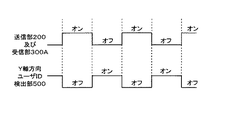
図9は、受信部300AとY軸方向ユーザID検出部500とを有するマルチタッチ・マルチユーザ検出装置の場合の各部の動作期間を説明するための図である。図9に示すように、送信部200及び受信部300Aを動作させると共にY軸方向ユーザID検出部500を停止させる期間と、送信部200及び受信部300Aを停止させると共にY軸方向ユーザID検出部500を動作させる期間とを交互に設ける。当該制御は、制御部40が各部を制御することにより行うことができる。
FIG. 9 is a diagram for explaining an operation period of each unit in the case of a multi-touch / multi-user detection apparatus including the
このようにすれば、送信部200と受信部300Aが動作する期間では、X軸方向のマルチユーザの検出とマルチタッチの検出とを確実に行うことができる。そして、Y軸方向ユーザID検出部500が動作する期間では、多周波信号が邪魔になることなく、Y軸方向のマルチユーザの検出を正確に行うことができる。
In this way, it is possible to reliably perform multi-user detection and multi-touch detection in the X-axis direction during the period in which the
また、図8を用いて説明した受信部300とX軸方向ユーザID検出部400とY軸方向ユーザID検出部500とを設ける構成の場合にも、同様の制御を行うようにすればよい。すなわち、送信部200を動作させると共にY軸方向ユーザID検出部500を停止させる期間と、送信部200を停止させると共にY軸方向ユーザID検出部500を動作させる期間とを交互に設けるようにすればよい。この場合、送信部200を動作させる期間では、受信部300とX軸方向ユーザID検出部400とについても動作させ、送信部200を停止させる期間では、受信部300とX軸方向ユーザID検出部400とについても停止させる。
Further, similar control may be performed even in the case of the configuration in which the receiving
このようにすれば、送信部200と受信部300とX軸方向ユーザID検出部400が動作する期間では、X軸方向のマルチユーザの検出とマルチタッチの検出とを確実に行うことができる。そして、Y軸方向ユーザID検出部500が動作する期間では、多周波信号が邪魔になることなく、Y軸方向のマルチユーザの検出を正確に行うことができる。
In this way, it is possible to reliably perform multi-user detection and multi-touch detection in the X-axis direction during the period in which the
また、図8を用いて説明したように、X軸方向ユーザID検出部400とY軸方向ユーザID検出部500との機能を、図2、図3を用いて説明した受信部300Aによって実現することもできる。すなわち、上述したように、X軸方向ユーザID検出部400のユーザID識別フィルタとY軸方向ユーザID検出部500のユーザID識別フィルタとは、図3を用いて説明したユーザID識別フィルタ331と同様に構成することができるものである。
In addition, as described with reference to FIG. 8, the functions of the X-axis direction user
このため、受信部300Aのユーザ及び位置識別回路33AのユーザID識別フィルタ331を、X軸方向のマルチユーザの検出とY軸方向のマルチユーザの検出とで兼用する。このため、図2に示したマルチタッチ・マルチユーザ検出装置1において、増幅回路31の前段に、受信導体群12の各受信導体からの信号と送信導体群11の各送信導体からの信号とのどちらを増幅回路31に供給するかを切り換える切換回路を設ける。
For this reason, the user of the receiving
そして、送信部200を動作させる期間と停止させる期間とを設けるようにする。この場合、受信部300Aは常時動作状態とされる。そして、送信部200を動作させる期間では、受信導体群12を構成する各受信導体からの信号を増幅回路31に供給し、送信部200を停止させる期間では、送信導体群11を構成する各送信導体からの信号を増幅回路31に供給するように当該切換回路を切り換えるようにする。
Then, a period for operating the
これにより、送信部200を動作させる期間では、受信部300Aにおいて、X軸方向のマルチユーザの検出とマルチタッチの検出とを行うことができる。一方、送信部200を停止させる期間では、受信部300Aにおいて、Y軸方向のマルチユーザの検出を行うことができる。このようにすれば、X軸方向ユーザID検出部400とY軸方向ユーザID検出部500とを設けることなく、これらを設けた場合と同様の検出結果を、受信部300Aによって得ることができるようにされる。
Thereby, in the period during which the
また、図2を用いて説明した受信部300Aと図8に示したY軸方向ユーザID検出部500とを設ける場合、受信部300Aにおいて複数のユーザによる位置指示操作が検出されたときには、Y軸方向ユーザID検出部500を動作させるようにすればよい。つまり、受信部300Aのユーザ及び位置識別回路33Aの検出結果に基づいて、位置検出回路33Aにおいて、複数のユーザにより位置指示操作が行われたことを検出した場合に、当該検出結果に基づいて、制御部40がY軸方向ユーザID検出部500を動作させる。
Further, when the receiving
これにより、複数のユーザが位置指示操作を行った場合にのみ、Y軸方向ユーザID検出部500を動作させ、各ユーザの指示を正確に検出することができる。換言すれば、1人のユーザしか位置指示操作を行っていない場合には、Y軸方向ユーザID検出部500を動作させるまでもなく、各指示体により指示された位置は、誰により指示されたかは明らかである。このような場合にまで、無駄にY軸方向ユーザID検出部500を動作させることもないようにされる。
Thereby, only when a plurality of users perform a position instruction operation, the Y-axis direction user
同様に、図8を用いて説明したように、受信部300と、X軸方向ユーザID検出部400と、Y軸方向ユーザID検出部500とを設けた構成にする場合にも同様のことが言える。この場合には、X軸方向ユーザID検出部400のユーザID識別フィルタによるユーザIDの検出結果に基づいて、X軸方向ユーザID検出部400のユーザ検出回路において、複数のユーザにより位置指示操作が行われたことを検出した場合に、当該検出結果に基づいて、制御部40がY軸方向ユーザID検出部500を動作させる。
Similarly, as described with reference to FIG. 8, the same applies to a configuration in which the receiving
これにより、複数のユーザが位置指示操作を行った場合にのみ、Y軸方向ユーザID検出部500を動作させ、各ユーザの指示を正確に検出することができる。換言すれば、1人のユーザしか位置指示操作を行っていない場合には、Y軸方向ユーザID検出部500を動作させるまでもなく、各指示体により指示された位置は、誰により指示されたかは明らかである。このような場合にまで、無駄にY軸方向ユーザID検出部500を動作させることもないようにされる。
Thereby, only when a plurality of users perform a position instruction operation, the Y-axis direction user
このように、図2に示した受信部300Aの位置検出回路34Aはユーザ及び位置識別回路33Aの検出結果に基づいて、マルチユーザによる操作状態にあるか単一ユーザによる操作状態にあるか否かを示す情報を生成して、制御部40に通知できるようにする。また、図8に示したX軸方向ユーザID検出部400のユーザ検出回路は、ユーザID識別フィルタによるユーザIDの検出結果に基づいて、マルチユーザによる操作状態にあるか単一ユーザによる操作状態にあるか否かを示す情報を生成して、制御部40に通知できるようにする。このようにすれば、無駄にY軸方向ユーザID検出部500を動作させることもないようにすることができる。
As described above, the
[信号発生器2の実施態様]
上述したように、この実施の形態のマルチタッチ・マルチユーザ検出装置1に対して指示操作を行う各ユーザは、マルチユーザの検出を可能にするため、ユーザ毎に異なる周波数の信号を発生させる信号発生器2を備える。この信号発生器2は、所定電圧レベル以上の信号を発生させることができればよいので、種々の形態で実現することができる。
[Embodiment of Signal Generator 2]
As described above, each user who performs an instruction operation on the multi-touch /
図10は、信号発生器2の実施態様を説明するための図である。信号発生器2は、ユーザが身に付けることにより、ユーザの身体及び指示体を通じて、マルチタッチ・マルチユーザ検出装置1に対してユーザ毎に異なる周波数の信号を供給するものである。このため、信号発生器2は、図10に示すように、ユーザの腕に装着される腕輪2aの構成としたり、ユーザの首に装着されるネックレス2bやペンダントの構成としたり、ユーザの指に装着される指輪2cの構成としたりすることができる。また、信号発生器2は、図10に示すように、ユーザの腕に装着される腕時計2dの構成としたり、ユーザの顔面部に装着される眼鏡2eの構成としたりすることもできる。
FIG. 10 is a diagram for explaining an embodiment of the signal generator 2. When the user wears the signal generator 2, the signal generator 2 supplies a signal having a different frequency for each user to the multi-touch /
この他、図示しないが、信号発生器2は、名刺入れや手帳サイズの箱型のものとし、これをユーザの衣服のポケットなどに入れて用いる構成とするなどのことも可能である。また、信号発生器2自体は、マルチタッチ・マルチユーザ検出装置1が設けられる情報処理装置側に設け、この情報処理装置側に設けた信号発生器2からの信号を、ケーブル等を通じてユーザに供給し、当該ユーザの身体及び指示体を通じてマルチタッチ・マルチユーザ検出装置1に供給する構成とすることも可能である。
In addition, although not shown, the signal generator 2 can be a business card holder or a notebook-sized box, and can be used by putting it in a pocket of a user's clothes. The signal generator 2 itself is provided on the information processing apparatus side where the multi-touch /
[変形例等]
[基本的な構成]
上述した実施の形態においては、図2、図3を用いて説明したように、複数の第1の導体に所定の信号を供給し、複数の第2の導体からの信号を受信し、複数の指示位置と、指示体識別情報とを検出して、どの位置がどの指示体により指示されたかを検出した。この場合、増幅回路31やA/D変換回路32を有する受信部300Aにおいて、指示体識別情報(ユーザID)を検出できるようにした。また、複数の第1の導体には周波数の異なる信号を供給すると共に、これらとは異なる周波数の信号を各指示体から供給するようにして、マルチタッチとマルチユーザの検出を可能にした。
[Modifications, etc.]
[Basic configuration]
In the above-described embodiment, as described with reference to FIGS. 2 and 3, a predetermined signal is supplied to a plurality of first conductors, a signal from the plurality of second conductors is received, and a plurality of signals are received. The indicated position and the indicator identification information are detected to detect which position is indicated by which indicator . In this case, the indicator identification information (user ID) can be detected in the receiving
[符号多重方式、位相シフト方式の利用]
しかし、これに限るものではない。複数の第1の導体に供給する信号や各指示体から第2の導体に供給される信号は、周波数の異なる信号に替えて、コードパターンが異なる複数のコードを使用するようにすることもできる。ここで、コードパターンが異なる複数のコードの例としては、異なるPN(pseudorandom noise)符号などの拡散符号を用いるようにしたり、同一のコードパターンで互いに位相が異なる複数のコードを用いるようにしたりすることもできる。このようにコードパターンが異なる複数のコードを用いるようにする場合、マルチタッチやマルチユーザの検出は、使用するコードに対応したコードとの相関値を検出することにより行うことが可能である。
[Use of code multiplex method and phase shift method]
However, it is not limited to this. A signal supplied to a plurality of first conductors or a signal supplied from each indicator to the second conductor can be replaced with a signal having a different frequency, and a plurality of codes having different code patterns can be used. . Here, as examples of a plurality of codes having different code patterns, spread codes such as different PN (pseudorandom noise) codes may be used, or a plurality of codes having the same code pattern and different phases may be used. You can also When a plurality of codes having different code patterns are used as described above, multi-touch and multi-user detection can be performed by detecting a correlation value with a code corresponding to the code to be used.
より具体的には、上述したように、符号多重方式を用いたクロスポイント型静電結合方式の指示体検出装置についての出願である特願2009−288273の出願書類や、位相シフト方式を用いたクロスポイント型静電結合方式の指示体検出装置についての出願の公開公報である特許文献2(特開2011−3036号公報)に詳しく開示されている。そして、マルチユーザの検出についても、マルチタッチの検出と同様にして行うことができる。 More specifically, as described above, the application document of Japanese Patent Application No. 2009-288273, which is an application for a cross-point type electrostatic coupling type indicator detection apparatus using a code multiplexing method, or a phase shift method was used. This is disclosed in detail in Patent Document 2 (Japanese Patent Application Laid-Open No. 2011-3036), which is a publication of an application regarding a cross-point type electrostatic coupling type indicator detection device. Multi-user detection can be performed in the same manner as multi-touch detection.
また、上述したように、複数の第1の導体のそれぞれ毎に、周波数の異なる信号やコードパターンが異なる信号を供給するようにしてもよいが、これに限るものではない。複数の第1の導体と、複数の第2の導体とのそれぞれについて、所定の数の導体毎にグループ化する。そして、複数の第1の導体については、グループ毎に異なる信号を用いるようにし、当該信号を供給する第1の導体を順次に切り換えるようにする。また、複数の第2の導体についても、グループ毎に受信した信号を出力する導体を切り換え、受信した信号の検出を導体毎に順次に行うようにする。 Further, as described above, a signal having a different frequency or a signal having a different code pattern may be supplied to each of the plurality of first conductors, but the present invention is not limited to this. Each of the plurality of first conductors and the plurality of second conductors is grouped for each predetermined number of conductors. And about a some 1st conductor, a different signal is used for every group, and the 1st conductor which supplies the said signal is switched sequentially. In addition, for the plurality of second conductors, the conductor that outputs the received signal is switched for each group, and the detection of the received signal is sequentially performed for each conductor.
このように、第1、第2の導体をグループ化して、グループ単位で処理を行うようにすることにより、第1の導体に供給すべき信号の種類を少なくすることができ、また、回路構成の単純化を図ることができるようにされる。なお、グループ化の具体的な手法についても、上述した特許文献1、2、及び、特願2009−288273の出願書類に開示されている方式を用いるようにすることができる。
Thus, by grouping the first and second conductors and performing processing in units of groups, the types of signals to be supplied to the first conductor can be reduced, and the circuit configuration can be reduced. It will be possible to simplify. In addition, also about the specific method of grouping, the system currently disclosed by the
[センサ導体の一面側に表示装置を配置、EMR方式の使用]
また、図7を用いて説明したように、ディスプレイ装置(表示装置)3Aをマルチタッチ・マルチユーザ検出装置1のセンサ導体の一面側、具体的には、指示体が位置を指示する側と同じ側に設けるようにすることができる。この場合、ディスプレイ装置3Aの表示面側とは反対に位置する裏面側にマルチタッチ・マルチユーザ検出装置1を設けることができるので、マルチタッチ・マルチユーザ検出装置1としては、EMR(Electromagnetic resonator)方式のものを用いることができる。
[Display device placed on one side of sensor conductor, using EMR method]
Further, as described with reference to FIG. 7, the display device (display device) 3 </ b> A is the same as the one side of the sensor conductor of the multi-touch /
ここで、EMR方式の検出装置は、よく知られているように、指示体としての電子ペンによって指示される位置を検出するセンサボードとコントロールボードとにより構成されるものである。センサボードは、縦横方向に多数のループコイルが配置された薄いフィルム形状をしている。センサボードの背面には、マザーボードなどの他の基板や回路からのノイズを遮蔽するシールド板が設けられている。また、コントロールボードは、センサボードに配置されたループコイルの順次に切り替えて交流電流を流すことができるものである。これにより、ループコイルから磁界が発生し、この磁界の中を指示体としての電子ペンが通過すると当該電子ペンの共振回路により当該電子ペンにエネルギーが蓄えられる。 Here, as is well known, the EMR detection device is configured by a sensor board and a control board that detect a position indicated by an electronic pen as an indicator. The sensor board has a thin film shape in which a large number of loop coils are arranged in the vertical and horizontal directions. On the back surface of the sensor board, there is provided a shield plate for shielding noise from other substrates such as a mother board and circuits. In addition, the control board is capable of flowing an alternating current by sequentially switching the loop coils arranged on the sensor board. As a result, a magnetic field is generated from the loop coil, and when the electronic pen as the indicator passes through the magnetic field, energy is stored in the electronic pen by the resonance circuit of the electronic pen.
次に、コントロールボードはループコイルへの電流供給を停止し、ループコイルを受信回路に接続する。すると、電子ペンの共振回路の自由振動により、電子ペンに蓄えられたエネルギーがペン先のコイルからセンサボードへと送り返される。電子ペンからのエネルギーはセンサボードにより受信され、受信回路を経由してA/D変換され、情報として検出される。コントロールボードは、センサボード上のループコイルを順次に切り替えて検出信号を計算することにより、センサボード上の電子ペンの座標値を精度良く算出し、特定することができる。 Next, the control board stops supplying current to the loop coil, and connects the loop coil to the receiving circuit. Then, the energy stored in the electronic pen is sent back from the pen tip coil to the sensor board by the free vibration of the resonance circuit of the electronic pen. The energy from the electronic pen is received by the sensor board, A / D converted via the receiving circuit, and detected as information. The control board can calculate and specify the coordinate value of the electronic pen on the sensor board with high accuracy by sequentially switching the loop coils on the sensor board and calculating the detection signal.
そして、このEMR方式を用いてマルチタッチ、マルチユーザ検出装置を構成した場合、電子ペンからセンサボードに送り返す信号を、電子ペン毎に異なるようにすることにより、指示位置だけでなく、電子ペン毎の識別をも行うことができる。すなわち、EMR方式の検出方式を用いることによっても、この発明のマルチタッチ、マルチユーザ検出装置を実現できる。なお、EMR方式の座標入力装置に関する基本的な技術は、例えば、特開昭64−53223号公報等に開示されている。 When a multi-touch, multi-user detection device is configured using this EMR method, the signal sent back from the electronic pen to the sensor board is made different for each electronic pen, so that not only the indicated position but also each electronic pen. Can also be identified. That is, the multi-touch and multi-user detection device of the present invention can be realized by using an EMR detection method. A basic technique related to an EMR type coordinate input apparatus is disclosed in, for example, Japanese Patent Application Laid-Open No. 64-53223.
[検出装置と表示装置との積層]
また、図1を用いて説明したように、マルチタッチ・マルチユーザ検出装置1のセンサ導体の一面側に指示体が対向し、他面側に表示装置を配設することもできる。簡単には、マルチタッチ・マルチユーザ検出装置1の下側にディスプレイ装置(表示装置)3を設けた重畳構造とすることができる。
[Lamination of detection device and display device]
In addition, as described with reference to FIG. 1, the indicator may be opposed to one surface side of the sensor conductor of the multi-touch /
[静電方式、抵抗膜方式の利用]
この場合に、マルチタッチ・マルチユーザ検出装置1としては、上述したクロスポイント型静電結合方式等のいわゆる静電方式を用いる他に、透過性を有する検出装置として、抵抗膜方式を用いてマルチタッチ・マルチユーザ検出装置を実現することもできる。
[Use of electrostatic system and resistive film system]
In this case, as the multi-touch /
ここで、抵抗膜方式のタッチセンサは、簡単にはベースとなるガラス面の表面に非常に小さなスペーサ(数μm(マイクロメートル))を挟み、その表面にしなやかなフィルム(200μm程度)を貼り付けて構成する。当該ガラスと当該フィルムの向かい合う面には、例えばITO(Indium Tin Oxide)の透明な電極格子(複数の第1、第2の導体)が設けられる。 Here, the touch sensor of the resistive film type simply puts a very small spacer (several μm (micrometer)) on the surface of the glass surface as a base, and attaches a flexible film (about 200 μm) on the surface. Configure. For example, ITO (Indium Tin Oxide) transparent electrode grids (a plurality of first and second conductors) are provided on the opposing surfaces of the glass and the film.
このように構成される抵抗膜方式のタッチセンサにおいては、指示体によりタッチされていない状態では、微小なスペーサにより対向する電極は接触していないために電流は流れない。しかし、フィルム面を指等の指示体によりタッチすると圧力によりフィルムが撓み、対向する電極が接触し電流が流れる。そして、ガラス面及びフィルム面のそれぞれの透明電極の抵抗による分圧比を測定することで指示体の接触位置を検出することができるようにされる。 In the resistive film type touch sensor configured as described above, when the electrode is not touched by the indicator, no current flows because the opposing electrodes are not in contact with each other by the minute spacer. However, when the film surface is touched with an indicator such as a finger, the film is bent by the pressure, the opposing electrodes come into contact with each other, and a current flows. The contact position of the indicator can be detected by measuring the partial pressure ratio due to the resistance of the transparent electrodes on the glass surface and the film surface.
この場合に、指示体から指示体毎に異なる信号(周波数やコードパターンが異なる信号)を供給し、これを格子状に配設される電極に対応して検出すれば、指示位置毎に指示体の識別も行うことができる。すなわち、抵抗膜方式の検出方式を用いることによっても、この発明のマルチタッチ、マルチユーザ検出装置を実現できる。 In this case, if a different signal (a signal having a different frequency or code pattern) is supplied from the indicator to each indicator, and this is detected corresponding to the electrodes arranged in a grid pattern, the indicator for each indicated position Can also be identified. That is, the multi-touch, multi-user detection device of the present invention can be realized also by using a resistance film type detection method.
[第2の指示体識別情報検出回路の利用]
また、図8、図9を用いて説明したように、Y軸方向ユーザID検出部500を設け、当該Y軸方向ユーザID検出部500での検出処理を行う期間においては、第1の導体には信号を供給しないようにすることを説明した。この場合、第1の導体に信号を供給する期間と、第1の導体への信号の供給を停止して、Y軸方向ユーザID検出部500で検出処理を実行する期間は、必ずしも等しい時間期間とする必要はない。Y軸方向ユーザID検出部500の動作期間よりも、第1の導体に信号を供給し、受信部300Aや受信部300及びX軸方向ユーザID検出部400を動作させる期間を長くしたり、また、その逆としたりすることもできる。
[Use of Second Indicator Identification Information Detection Circuit]
In addition, as described with reference to FIGS. 8 and 9, the Y-axis direction user
第1の導体に信号を供給する期間は、受信部300A、あるいは、受信部300A及びX軸方向ユーザID検出部400での処理が適正に実行可能な期間とすればよい。また、第1の導体に信号を供給しない期間は、Y軸方向ユーザID検出部500での処理が適正に実行可能な期間とすればよい。
The period during which the signal is supplied to the first conductor may be a period in which the processing in the receiving
[第1、第2の指示体識別情報検出回路の利用]
また、上述したように、受信部300AとY軸方向ユーザID検出部500とを常時一緒に用いるようにしたり、受信部300及びX軸方向ユーザID検出部400とY軸方向ユーザID検出部500とを常時一緒に用いるようにしたりすることも可能である。また、受信部300AまたはX軸方向ユーザID検出部400において、複数のユーザが指示体を用いた指示操作を行っていることを検出した場合に、Y軸方向ユーザID検出部500を機能させるようにすることもできる。
[Use of first and second indicator identification information detection circuits]
Further, as described above, the receiving
[指示位置の形状、色による識別]
また、図6、図7を用いて説明したように、指示位置を指示体毎に形状、色によって互いに識別できるようにすることができる。この場合、形状は四角形や円形の他、星型、三角形以上の多角形などを用いることができるし、色もディスプレイ装置3、3Aが表現可能な種々の色を用いることが可能である。
[Identification of the indicated position by shape and color]
In addition, as described with reference to FIGS. 6 and 7, it is possible to distinguish the pointing positions from each other by shape and color for each pointer. In this case, the shape may be a square or a circle, a star shape, a polygon more than a triangle, and the like, and the colors may be various colors that can be expressed by the display devices 3 and 3A.
[領域の枠線、背景色による識別]
また、指示体により操作が行われる領域を枠線や背景色を変えることにより示すようにすることもできる。この場合、枠線の線種や背景色も、ディスプレイ3、3Aにおいて表示可能な種々のものを用いることができる。
[Identification by area border and background color]
It is also possible to indicate the area operated by the indicator by changing the frame line or the background color. In this case, various line types and background colors that can be displayed on the displays 3 and 3A can be used.
[領域の移動、情報のコピー、移動等]
また、ユーザによって設定される表示領域自体をディスプレイ装置3、3Aの表示画面において適宜の位置に移動させるようにしたり、表示領域に表示されている情報の他の表示領域へのコピー、移動のほか、追加や削除など、種々の編集作業を行えるようにしたりすることも可能である。当該処理は、マルチタッチ・マルチユーザ検出装置1へのユーザの操作入力に基づいて、表示制御装置(パーソナルコンピュータ)4、4Aが実現する。
[Move areas, copy information, move, etc.]
In addition to moving the display area itself set by the user to an appropriate position on the display screens of the display devices 3 and 3A, copying the information displayed in the display area to other display areas, moving the display area, etc. It is also possible to perform various editing operations such as addition and deletion. The processing is realized by the display control devices (personal computers) 4 and 4A based on user operation input to the multi-touch /
[マルチユーザか単一ユーザかの検出出力]
また、上述したように、受信部300やX軸方向ユーザID検出部400においては、各指示体を用いているユーザの検出が可能である。このため、受信部300やX軸方向ユーザID検出部400は、指示体を用いて操作入力を行っているのは、単独ユーザか複数ユーザの別を出力するようにしたり、指示体を用いて操作入力を行っているユーザの数を出力したりすることができる。
[Detection output of multi-user or single user]
Further, as described above, the
[第1、第2の導体の他の構成例]
なお、直線状に形成された送信導体11Yと受信導体12Xとを直交するように配置した場合を例示して説明したが、送信導体11Yおよび受信導体12Xの形状は、実施の態様に応じて適宜設定される。また、送信導体11Yと受信導体12Xとは直交以外の角度、例えば、送信導体11Yと受信導体12Xとが斜めに交差する構成としても良い。
[Other configuration examples of the first and second conductors]
In addition, although the case where the
また、電気特性上、受信導体12Xの幅は送信導体11Yの幅より細く形成すると良い。浮遊容量が減ることにより、受信導体12Xに混入するノイズを低減できるからである。
Further, in terms of electrical characteristics, the width of the
また、送信導体11Y及び受信導体12Xの少なくとも一方を曲線状あるいは同心円状に形成した導体で構成してもよい。例えば複数の送信導体11Yをそれぞれ径の異なる円形状に形成し、これを同心円状に配置すると共に、複数の受信導体12Xを前記同心円の中心から放射状に延伸した直線形状の複数の導体により形成し、その複数の直線形状の導体を周方向に等角間隔で配置するようにしても良い。
Further, at least one of the
すなわち、送信導体11Y及び受信導体12Xの構成は、例えば、特開2011−3035公報の図15〜図20に開示されているような種々のものすることが可能である。
That is, the configurations of the
[その他]
なお、上述した実施の形態においては、ユーザ毎に信号発生器2を設けるものとして説明した。この場合、1人のユーザが自分の複数の指を指示体として用いて同時にセンサ部100に接触した場合であっても、同じユーザの異なる指によって指示された指示位置は、同じユーザによって指示された指示位置として検出することができる。
[Others]
In the above-described embodiment, it has been described that the signal generator 2 is provided for each user. In this case, even when one user uses his / her multiple fingers as an indicator and touches the sensor unit 100 at the same time, the indicated position indicated by different fingers of the same user is indicated by the same user. The detected position can be detected.
また、例えば、タッチペンなどの指示体毎に発振回路を設けるようにした場合には、同じユーザが異なる指示体を用いて指示入力を行うと、それぞれの指示体毎に指示位置を区別して検出することができる。つまり、1人のユーザが異なる指示体(タッチペン)を用いて指示入力を行った場合には、ユーザ毎ではなく、指示体毎に指示位置を特定することができる。 Also, for example, when an oscillation circuit is provided for each indicator such as a touch pen, when the same user inputs an instruction using different indicators, the indication position is detected for each indicator separately. be able to. That is, when one user inputs an instruction using a different indicator (touch pen), the indicated position can be specified for each indicator, not for each user.
1…マルチタッチ・マルチユーザ検出装置、100…センサ部、100S…指示入力面、11…送信導体群、11Y1〜11Y64…送信導体、12…受信導体群、12X 1 〜12X 64 …受信導体、200…送信部、21…送信信号供給回路、22…クロック生成回路、300…受信部、31…増幅回路、32…A/D変換回路、33A…ユーザ及び位置識別回路、331…ユーザID識別フィルタ、332…指示位置識別フィルタ、34A…位置検出回路、40…制御回路、2、2A、2B…信号発生器、3、3A…ディスプレイ装置(表示装置)、4、4A…表示制御装置、300…受信部、400…X軸方向ユーザID検出部、500…Y軸方向ユーザID検出部
1 ... Multi-touch and multi-user detection device, 100 ... sensor unit, 100S ... pointing input surface, 11 ...
Claims (17)
前記第1の方向に配置された前記複数の第1の導体のうち2本以上の導体に所定の信号を同時に供給するための信号送信回路と、
前記第2の方向に配置された前記複数の第2の導体からの信号を受信する信号受信回路と、
前記信号受信回路から出力された信号に基づいて、前記センサ導体に対する複数の指示体のそれぞれの位置を検出する位置検出回路と、
前記センサ導体からの信号に基づいて、前記信号送信回路から前記第1の方向に配置された複数の第1の導体に供給される信号とは識別可能な指示体識別情報を検出する第1の指示体識別情報検出回路と、
前記位置検出回路により検出された前記指示体の位置情報と、前記第1の指示体識別情報検出回路により検出された前記指示体識別情報に基づいて、前記複数の指示体によって指示された位置がいずれの指示体による指示であるかの対応関係を特定するための対応関係特定回路と、
を備えることで、
前記センサ導体に対する前記複数の指示体のそれぞれの位置と、前記複数の指示体との対応関係が特定できるようにしたことを特徴とするマルチタッチ・マルチユーザ検出装置。 A plurality of first conductors arranged in a first direction and a sensor conductor composed of a plurality of second conductors arranged in a second direction intersecting the first direction;
A signal transmission circuit for simultaneously supplying a predetermined signal to two or more of the plurality of first conductors arranged in the first direction;
A signal receiving circuit for receiving signals from the plurality of second conductors arranged in the second direction;
A position detection circuit that detects positions of a plurality of indicators with respect to the sensor conductor based on a signal output from the signal receiving circuit;
Based on a signal from the sensor conductor, a first indicator identifying information that is distinguishable from signals supplied from the signal transmission circuit to the plurality of first conductors arranged in the first direction is detected. An indicator identification information detection circuit;
Based on the position information of the indicator detected by the position detection circuit and the indicator identification information detected by the first indicator identification information detection circuit, the positions indicated by the plurality of indicators are A correspondence specifying circuit for specifying the correspondence of which indicator is an instruction;
By providing
A multi-touch / multi-user detection apparatus characterized in that a correspondence relationship between each position of the plurality of indicators with respect to the sensor conductor and the plurality of indicators can be specified.
前記信号送信回路から前記センサ導体に供給される信号とは識別可能な前記指示体識別情報を送出する信号発生手段を備える、
ことを特徴とする指示体。 A signal transmission circuit that simultaneously supplies a predetermined signal to two or more conductors of a plurality of sensor conductors arranged in a predetermined direction, and the sensor conductor based on a signal received from the sensor conductor Multi-touch for identifying the position of each of the plurality of pointers and the correspondence of which pointer is the direction by detecting indicator identification information that can be distinguished from the predetermined signal supplied An indicator used in a multi-user detection device,
Comprising signal generating means for sending the indicator identification information identifiable from the signal supplied from the signal transmission circuit to the sensor conductor;
An indicator characterized by that.
前記複数の指示体は、それぞれが固有の指示体識別情報を送出する信号発生器を有し、
前記検出装置は、
第1の方向に配置された複数の第1の導体と、前記第1の方向に対して交差する第2の方向に配置された複数の第2の導体からなるセンサ導体と、
前記センサ導体のうち2本以上の導体に所定の信号を同時に供給するための信号送信回路と、
前記センサ導体からの信号を受信する信号受信回路と、
前記信号受信回路から出力された信号に基づいて、前記センサ導体に対する複数の指示体のそれぞれの位置を検出する位置検出回路と、
前記センサ導体からの信号に基づいて、前記信号送信回路から前記センサ導体に供給される信号とは識別可能な指示体識別情報を検出する指示体識別情報検出回路と、
前記位置検出回路により検出された前記指示体の位置情報と、前記指示体識別情報検出回路により検出された前記指示体識別情報に基づいて、前記複数の指示体によって指示された位置がいずれの指示体による指示であるかの対応関係を特定するための対応関係特定回路と、
を備えることで、前記センサ導体に対する前記複数の指示体のそれぞれの位置と、前記複数の指示体との対応関係が特定できるようにした、
ことを特徴とするマルチタッチ・マルチユーザ検出システム。 A multi-touch multi-user detection system comprising a plurality of indicators and a detection device,
Each of the plurality of indicators has a signal generator for transmitting unique indicator identification information,
The detection device includes:
A plurality of first conductors arranged in a first direction and a sensor conductor composed of a plurality of second conductors arranged in a second direction intersecting the first direction;
A signal transmission circuit for simultaneously supplying a predetermined signal to two or more of the sensor conductors;
A signal receiving circuit for receiving a signal from the sensor conductor;
A position detection circuit that detects positions of a plurality of indicators with respect to the sensor conductor based on a signal output from the signal receiving circuit;
An indicator identification information detection circuit for detecting indicator identification information identifiable from a signal supplied from the signal transmission circuit to the sensor conductor based on a signal from the sensor conductor;
Based on the position information of the indicator detected by the position detection circuit and the indicator identification information detected by the indicator identification information detection circuit, the position indicated by the plurality of indicators is any indication. A correspondence identifying circuit for identifying the correspondence of whether it is an instruction by the body;
By providing the position of each of the plurality of indicators relative to the sensor conductor, the correspondence relationship between the plurality of indicators can be specified,
A multi-touch multi-user detection system.
Priority Applications (9)
| Application Number | Priority Date | Filing Date | Title |
|---|---|---|---|
| JP2011100348A JP5743198B2 (en) | 2011-04-28 | 2011-04-28 | Multi-touch multi-user detection device |
| IL218563A IL218563A (en) | 2011-04-28 | 2012-03-08 | Device and method for detecting multi-touch of multi-user |
| US13/419,107 US9081437B2 (en) | 2011-04-28 | 2012-03-13 | Multi-touch and multi-user detecting device |
| TW101109848A TWI563421B (en) | 2011-04-28 | 2012-03-22 | Multi-touch and multi-user detecting device, indicators, and system |
| EP12163728.4A EP2518603B1 (en) | 2011-04-28 | 2012-04-11 | Multi-touch and multi-user detecting device |
| KR1020120040288A KR101898291B1 (en) | 2011-04-28 | 2012-04-18 | Multi-touch and multi-user detecting device |
| CN201210132306.3A CN102760007B (en) | 2011-04-28 | 2012-04-28 | Multi-contact and multi-user detection device |
| CN201610902141.1A CN107015681B (en) | 2011-04-28 | 2012-04-28 | Multi-touch and multi-user detection apparatus and method |
| US14/732,405 US10031634B2 (en) | 2011-04-28 | 2015-06-05 | Multi-touch and multi-user detecting device |
Applications Claiming Priority (1)
| Application Number | Priority Date | Filing Date | Title |
|---|---|---|---|
| JP2011100348A JP5743198B2 (en) | 2011-04-28 | 2011-04-28 | Multi-touch multi-user detection device |
Publications (3)
| Publication Number | Publication Date |
|---|---|
| JP2012234230A JP2012234230A (en) | 2012-11-29 |
| JP2012234230A5 JP2012234230A5 (en) | 2014-12-04 |
| JP5743198B2 true JP5743198B2 (en) | 2015-07-01 |
Family
ID=46027628
Family Applications (1)
| Application Number | Title | Priority Date | Filing Date |
|---|---|---|---|
| JP2011100348A Active JP5743198B2 (en) | 2011-04-28 | 2011-04-28 | Multi-touch multi-user detection device |
Country Status (7)
| Country | Link |
|---|---|
| US (2) | US9081437B2 (en) |
| EP (1) | EP2518603B1 (en) |
| JP (1) | JP5743198B2 (en) |
| KR (1) | KR101898291B1 (en) |
| CN (2) | CN102760007B (en) |
| IL (1) | IL218563A (en) |
| TW (1) | TWI563421B (en) |
Families Citing this family (99)
| Publication number | Priority date | Publication date | Assignee | Title |
|---|---|---|---|---|
| JP5929572B2 (en) * | 2012-07-09 | 2016-06-08 | コニカミノルタ株式会社 | Operation display device and program |
| US20140043277A1 (en) * | 2012-08-09 | 2014-02-13 | Nokia Corporation | Apparatus and associated methods |
| KR20140021899A (en) * | 2012-08-13 | 2014-02-21 | 삼성전자주식회사 | Method for moving contents and an electronic device thereof |
| TWI485610B (en) * | 2012-12-28 | 2015-05-21 | Egalax Empia Technology Inc | Method and device for detecting touch or proximity |
| CN103838414B (en) * | 2012-11-27 | 2018-10-12 | 联想(北京)有限公司 | A kind of recognition methods and a kind of electronic equipment |
| CN103870041B (en) * | 2012-12-14 | 2017-09-22 | 联想(北京)有限公司 | terminal device and its user identification method |
| JP2014160415A (en) * | 2013-02-20 | 2014-09-04 | Fuji Xerox Co Ltd | Browsing device, browsing system, information processing apparatus, and program |
| JP2014178790A (en) * | 2013-03-14 | 2014-09-25 | Ricoh Co Ltd | Projection system, projection device, projection program, and projection method |
| US9710113B2 (en) | 2013-03-15 | 2017-07-18 | Tactual Labs Co. | Fast multi-touch sensor with user identification techniques |
| SG10201606730SA (en) * | 2013-03-15 | 2016-10-28 | Tactual Labs Co | Fast multi-touch noise reduction |
| US9830015B2 (en) * | 2013-03-15 | 2017-11-28 | Tactual Labs Co. | Orthogonal frequency scan scheme in touch system |
| US9507464B2 (en) | 2013-03-15 | 2016-11-29 | Elo Touch Solutions, Inc. | Acoustic touch apparatus and methods using touch sensitive lamb waves |
| KR102138512B1 (en) * | 2013-03-26 | 2020-07-28 | 엘지전자 주식회사 | Display Device And Controlling Method Thereof |
| CN103218075B (en) * | 2013-03-26 | 2016-12-28 | 深圳市金立通信设备有限公司 | The touch-control monitoring method of a kind of Touch Screen and terminal |
| US9182867B2 (en) * | 2013-04-25 | 2015-11-10 | Anapass Inc. | Apparatus and method for detecting adjacent object and method of driving electronic device |
| KR102131257B1 (en) | 2013-07-02 | 2020-07-07 | 삼성전자주식회사 | Electronic device and method for controlling multi- window in the electronic device |
| JP5882270B2 (en) * | 2013-08-29 | 2016-03-09 | 東芝テック株式会社 | Information processing apparatus and program |
| US11392221B2 (en) | 2013-11-08 | 2022-07-19 | Egalax_Empia Technology Inc. | Touch sensitive processing apparatus, system and operating method thereof for receiving electrical signals carrying pressure information |
| US11409379B2 (en) | 2013-11-08 | 2022-08-09 | Egalax_Empia Technology Inc. | Stylus and operating method thereof for transmitting electrical signals carrying pressure information |
| US10890987B2 (en) | 2013-11-08 | 2021-01-12 | Egalax_Empia Technology Inc. | Stylus and operating method thereof for transmitting electrical signals carrying pressure information |
| US10895921B2 (en) | 2013-11-08 | 2021-01-19 | Egalax_Empia Technology Inc. | Touch sensitive processing apparatus, system and operating method thereof for receiving electrical signals carrying pressure information |
| KR101460104B1 (en) * | 2014-01-24 | 2014-11-20 | 주식회사 아나패스 | Method for Driving an Electronic Device having A Touch Panel |
| WO2015129112A1 (en) * | 2014-02-28 | 2015-09-03 | 凸版印刷株式会社 | Lcd device |
| JP6269227B2 (en) | 2014-03-25 | 2018-01-31 | セイコーエプソン株式会社 | Display device, projector, and display control method |
| TWI641986B (en) * | 2014-06-01 | 2018-11-21 | 美商英特爾公司 | Method for determining a number of users and their respective positions relative to a device, electronic device and computer readable medium |
| US10867149B2 (en) | 2014-06-12 | 2020-12-15 | Verizon Media Inc. | User identification through an external device on a per touch basis on touch sensitive devices |
| US9396378B2 (en) * | 2014-06-12 | 2016-07-19 | Yahoo! | User identification on a per touch basis on touch sensitive devices |
| KR101538791B1 (en) * | 2014-06-18 | 2015-07-24 | 한국산업은행 | Interactive white board |
| EP3163421A4 (en) * | 2014-06-24 | 2018-06-13 | Sony Corporation | Information processing device, information processing method, and program |
| FR3027126B1 (en) * | 2014-10-10 | 2017-12-01 | Thales Sa | IDENTIFICATION AND DATA EXCHANGE SYSTEM COMPRISING A PORTABLE CAPACITIVE DEVICE AND A CAPACITIVE TOUCH SCREEN |
| US9720539B2 (en) * | 2014-11-25 | 2017-08-01 | Robert Dennis Kennedy | Tablet computer screen and mobile phone screen to digital I/O converter |
| JP6350261B2 (en) * | 2014-12-17 | 2018-07-04 | コニカミノルタ株式会社 | Object operation system, object operation control program, and object operation control method |
| CN104598071B (en) * | 2014-12-29 | 2018-04-27 | 联想(北京)有限公司 | A kind of information processing method and electronic equipment |
| CN107407983A (en) * | 2015-02-02 | 2017-11-28 | 坦吉阿莫触摸技术公司 | Multi-touch user interface for electronic equipment |
| EP3267293B1 (en) * | 2015-03-02 | 2019-09-18 | Wacom Co., Ltd. | Active capacitive stylus, sensor controller, system comprising these, and method executed by these |
| CN106257383B (en) * | 2015-06-16 | 2019-03-29 | 禾瑞亚科技股份有限公司 | Touch processing device, system and method for resolving spread spectrum signal |
| US10664098B2 (en) | 2015-06-22 | 2020-05-26 | Sigmasense, Llc. | Channel driver circuit |
| US11269455B1 (en) | 2020-10-23 | 2022-03-08 | Sigmasense, Llc. | Enhanced mutual capacitance touch screen display with noise compensation and methods for use therewith |
| JP6745808B2 (en) | 2015-06-22 | 2020-08-26 | シグマセンス,エルエルシー | Multi-touch sensor and electrostatic pen digitization system utilizing simultaneous features for improved performance |
| US11397492B2 (en) | 2015-06-22 | 2022-07-26 | Sigmasense, Llc. | Enhanced mutual capacitance touch screen display with shape detection and methods for use therewith |
| US11907484B2 (en) | 2015-06-22 | 2024-02-20 | Sigmasense, Llc. | Function and orientation identification for input/output (I/O) operative touch sensor device (TSD) |
| KR101948453B1 (en) | 2015-07-06 | 2019-02-14 | 시그마센스, 엘엘씨. | Pen system with internal pressure tilt rotation |
| JP2017102894A (en) * | 2015-10-30 | 2017-06-08 | パナソニックIpマネジメント株式会社 | Detection device |
| JP6426639B2 (en) * | 2016-02-25 | 2018-11-21 | ファナック株式会社 | Data transmission system, touch panel device, and data transmission method |
| KR102523154B1 (en) | 2016-04-22 | 2023-04-21 | 삼성전자주식회사 | Display apparatus, input device and control method thereof |
| US11129547B2 (en) | 2016-08-18 | 2021-09-28 | Athalonz, Llc | Wireless in-shoe physical activity monitoring |
| US10871896B2 (en) * | 2016-12-07 | 2020-12-22 | Bby Solutions, Inc. | Touchscreen with three-handed gestures system and method |
| KR102318808B1 (en) * | 2017-05-26 | 2021-10-28 | 삼성전자주식회사 | Method for using various type of electronic pen and electronic device thereof |
| CN107479820B (en) * | 2017-08-24 | 2021-01-08 | 深圳恒远智信科技有限公司 | Identification method of touch device, terminal equipment and server |
| US10838530B2 (en) | 2017-09-15 | 2020-11-17 | Sigmasense, Llc. | Touchscreen display with concurrent touch and display operations |
| US11099032B2 (en) | 2018-08-27 | 2021-08-24 | Sigmasense, Llc. | Drive sense circuit with drive-sense line |
| US11550426B2 (en) | 2018-08-27 | 2023-01-10 | Sigmasense, Llc. | Sensor monitoring system |
| US11644860B2 (en) | 2018-08-27 | 2023-05-09 | Sigmasense, Llc. | Configuring a programmable drive sense unit |
| US10895867B2 (en) | 2018-08-27 | 2021-01-19 | Sigmasense, Llc. | Analog world interfacing for automated systems |
| US11822358B2 (en) | 2018-08-27 | 2023-11-21 | Sigmasense, Llc. | Drive-sense circuit to determine effects of different electrical characteristics on load |
| US11513543B2 (en) | 2018-08-27 | 2022-11-29 | Sigmasense, Llc. | Impedance detect drive sense circuit |
| US11914812B2 (en) | 2018-08-27 | 2024-02-27 | Sigmasense, Llc. | Current reference operative drive-sense circuit (DSC) |
| US11429226B2 (en) | 2018-08-27 | 2022-08-30 | Sigmasense, Llc. | Analog-digital drive sense circuit |
| US11635396B2 (en) | 2018-08-27 | 2023-04-25 | Sigmasense, Llc. | Sensing device with drive sense circuit and particle sensor and methods for use therewith |
| US11789555B2 (en) | 2018-09-14 | 2023-10-17 | Sigmasense, Llc. | Touch sense control circuit with noise suppression |
| US10845985B2 (en) | 2018-09-14 | 2020-11-24 | Sigmasense, Llc. | Identification in touch systems |
| US11875005B2 (en) | 2018-09-14 | 2024-01-16 | Sigmasense, Llc. | Touch screen display with touchless indications and methods for use therewith |
| US10908718B2 (en) | 2018-09-14 | 2021-02-02 | Sigmasense, Llc. | Large touch screen display with integrated electrodes |
| US11899867B2 (en) | 2018-09-14 | 2024-02-13 | Sigmasense, Llc. | Touch screen display with touchless gestures and methods for use therewith |
| US11372510B2 (en) | 2018-11-02 | 2022-06-28 | Sigmasense, Llc. | Multi-conductor touch system |
| US10935585B2 (en) | 2018-11-19 | 2021-03-02 | Sigmasense, Llc. | Drive sense circuit with transient suppression |
| US10852857B2 (en) | 2018-11-19 | 2020-12-01 | Sigmasense, Llc. | Frequency diverse e-pen for touch sensor and e-pen systems |
| US10884967B2 (en) | 2019-01-14 | 2021-01-05 | Sigmasense, Llc. | Low voltage drive circuit with variable frequency characteristics and methods for use therewith |
| JP7152979B2 (en) * | 2019-03-28 | 2022-10-13 | シャープ株式会社 | Information processing equipment |
| US11029782B2 (en) | 2019-05-03 | 2021-06-08 | Sigmasense, Llc. | Light emitting diode (LED) touch display circuit |
| US11131714B2 (en) | 2019-05-31 | 2021-09-28 | Sigmasense, Llc. | Battery monitoring and characterization during charging |
| US11216133B2 (en) | 2019-06-10 | 2022-01-04 | Sigmasense, Llc. | Device for use with a touch screen |
| US11054920B2 (en) | 2019-06-10 | 2021-07-06 | Sigmasense, Llc. | Pen for use with a touch screen |
| US11029769B2 (en) | 2019-06-10 | 2021-06-08 | Sigmasense, Llc. | Pen for use with a touch screen |
| US11126297B2 (en) | 2019-06-10 | 2021-09-21 | Sigmasense, Llc. | Electronic pen with ring-back and other functionalities |
| US11221709B2 (en) | 2019-06-10 | 2022-01-11 | Sigmasense, Llc. | Electronic writing apparatus with ring-back and other functionalities |
| US11555687B2 (en) | 2019-08-08 | 2023-01-17 | Sigmasense, Llc. | Capacitive imaging glove |
| US10908641B1 (en) | 2019-10-09 | 2021-02-02 | Sigmasense, Llc. | Display generated data transmission from user device to touchscreen via user |
| US11216109B2 (en) | 2020-01-07 | 2022-01-04 | Sigmasense, Llc. | Drive-sense control for extended sensor panels |
| US11221704B2 (en) | 2020-02-05 | 2022-01-11 | Sigmasense, Llc. | Screen-to-screen communication via touch sense elements |
| TWI727662B (en) * | 2020-02-14 | 2021-05-11 | 李尚禮 | Resistive touch device and resistive touch-sensing method |
| US11079888B1 (en) | 2020-02-18 | 2021-08-03 | Sigmasense, Llc. | Sensitivity region of interest processing (ROIP) for input/output (I/O) operative touch sensor device (TSD) |
| US11144160B1 (en) | 2020-03-30 | 2021-10-12 | Sigmasense, Llc. | Three-dimensional data reduction method and system |
| US11182038B2 (en) | 2020-04-08 | 2021-11-23 | Sigmasense, Llc. | Encoded data pattern touchscreen sensing system |
| US11340995B2 (en) | 2020-05-21 | 2022-05-24 | Sigmasense, Llc. | Integrated circuit with programmable input/output module |
| WO2022014441A1 (en) * | 2020-07-16 | 2022-01-20 | ソニーグループ株式会社 | Display device, display method, and program |
| US11304002B2 (en) | 2020-08-12 | 2022-04-12 | Sigmasense, Llc. | Single transducer audio in/out device |
| US11287926B1 (en) * | 2020-09-25 | 2022-03-29 | Apple Inc. | System and machine learning method for detecting input device distance from touch sensitive surfaces |
| US11374587B1 (en) | 2021-02-25 | 2022-06-28 | Sigmasense, Llc. | Batteryless wireless sensor system |
| US20220342513A1 (en) * | 2021-04-23 | 2022-10-27 | Sigmasense, Llc. | Processing z-direction pressure indication of a passive pen |
| US11575851B2 (en) | 2021-05-28 | 2023-02-07 | Sigmasense, Llc. | Handheld communication device with drive-sense circuit based imaging array and methods for use therewith |
| US11575850B2 (en) | 2021-05-28 | 2023-02-07 | Sigmasense, Llc. | Imaging device with drive-sense circuit(s) and methods for use therewith |
| US11679678B2 (en) | 2021-06-28 | 2023-06-20 | Sigmasense, Llc. | Vehicle system for detecting and visually conveying vehicle button interaction |
| US20220413596A1 (en) * | 2021-06-28 | 2022-12-29 | Sigmasense, Llc. | Vehicle sensor system |
| US11556298B1 (en) | 2021-07-30 | 2023-01-17 | Sigmasense, Llc | Generation and communication of user notation data via an interactive display device |
| US11592874B1 (en) | 2021-08-04 | 2023-02-28 | Sigmasense, Llc. | Touch sensing in a flexible/foldable touch screen display |
| US11797139B2 (en) | 2021-09-21 | 2023-10-24 | Sigmasense, Llc. | Fingerprint scanning device incorporating drive-sense circuitry |
| US11709563B2 (en) | 2021-10-26 | 2023-07-25 | Sigmasense, Llc. | Touch-based device with interlaced electrode grids |
| US11740752B1 (en) | 2022-07-13 | 2023-08-29 | Sigmasense, Llc. | Device with signal generator |
Family Cites Families (29)
| Publication number | Priority date | Publication date | Assignee | Title |
|---|---|---|---|---|
| JP2608895B2 (en) | 1987-08-24 | 1997-05-14 | 株式会社ワコム | Coordinate input method and device |
| US5236199A (en) * | 1991-06-13 | 1993-08-17 | Thompson Jr John W | Interactive media system and telecomputing method using telephone keypad signalling |
| JPH05233127A (en) * | 1992-02-21 | 1993-09-10 | Graphtec Corp | Cordless digitizer |
| JP3225716B2 (en) * | 1993-10-28 | 2001-11-05 | ぺんてる株式会社 | Information input device |
| JPH0822355A (en) * | 1994-07-08 | 1996-01-23 | Sharp Corp | Signal transmission system of coordinate input device |
| JP2000148396A (en) * | 1998-11-06 | 2000-05-26 | Canon Inc | Information inputting device and method therefor |
| US6777922B2 (en) * | 2001-05-14 | 2004-08-17 | Sony Corporation | Information processing apparatus for inputting a signal, and method therefor |
| US6498590B1 (en) | 2001-05-24 | 2002-12-24 | Mitsubishi Electric Research Laboratories, Inc. | Multi-user touch surface |
| US8125459B2 (en) * | 2007-10-01 | 2012-02-28 | Igt | Multi-user input systems and processing techniques for serving multiple users |
| US20070139371A1 (en) * | 2005-04-04 | 2007-06-21 | Harsham Bret A | Control system and method for differentiating multiple users utilizing multi-view display devices |
| JP2006302046A (en) * | 2005-04-21 | 2006-11-02 | Fuji Xerox Co Ltd | Electronic white board system, information processing program, information processing device, and information processing method |
| US8970502B2 (en) | 2006-05-26 | 2015-03-03 | Touchtable Ab | User identification for multi-user touch screens |
| US8686964B2 (en) * | 2006-07-13 | 2014-04-01 | N-Trig Ltd. | User specific recognition of intended user interaction with a digitizer |
| TW200937268A (en) | 2008-02-26 | 2009-09-01 | Egalax Empia Technology Inc | Touch panel device capable of being used by multiple persons at the same time and its control device and method |
| CN101576770B (en) * | 2008-05-07 | 2011-09-21 | 联想(北京)有限公司 | System and method for multi-contact interaction |
| EP2300899A4 (en) * | 2008-05-14 | 2012-11-07 | 3M Innovative Properties Co | Systems and methods for assessing locations of multiple touch inputs |
| JP5137690B2 (en) | 2008-05-27 | 2013-02-06 | 株式会社ジャパンディスプレイウェスト | Electro-optical device and electronic apparatus equipped with the same |
| US20100083109A1 (en) * | 2008-09-29 | 2010-04-01 | Smart Technologies Ulc | Method for handling interactions with multiple users of an interactive input system, and interactive input system executing the method |
| US8683390B2 (en) * | 2008-10-01 | 2014-03-25 | Microsoft Corporation | Manipulation of objects on multi-touch user interface |
| US8477103B2 (en) | 2008-10-26 | 2013-07-02 | Microsoft Corporation | Multi-touch object inertia simulation |
| CN101441539B (en) * | 2008-12-30 | 2013-06-12 | 华为终端有限公司 | Electronic white board system, input device, processing device and processing method |
| TW201030568A (en) * | 2009-02-10 | 2010-08-16 | Taipei Nat University Of The Arts | Multi-person, multi-point touch-control stepping interactive system |
| JP5396167B2 (en) | 2009-06-18 | 2014-01-22 | 株式会社ワコム | Indicator detection apparatus and indicator detection method |
| JP5295008B2 (en) | 2009-06-18 | 2013-09-18 | 株式会社ワコム | Indicator detection device |
| CN102473059B (en) * | 2009-08-12 | 2015-06-24 | 瑟克公司 | Synchronous timed orthogonal measurement pattern for multi-touch sensing on touchpad |
| WO2011036710A1 (en) * | 2009-09-24 | 2011-03-31 | 株式会社 東芝 | Touch-type input device |
| JP5295090B2 (en) | 2009-12-18 | 2013-09-18 | 株式会社ワコム | Indicator detection device |
| CN101763198B (en) * | 2009-12-25 | 2012-03-28 | 中国船舶重工集团公司第七○九研究所 | Back projection type multi-point touch positioning method |
| JP2012022543A (en) | 2010-07-15 | 2012-02-02 | Panasonic Corp | Touch panel system |
-
2011
- 2011-04-28 JP JP2011100348A patent/JP5743198B2/en active Active
-
2012
- 2012-03-08 IL IL218563A patent/IL218563A/en active IP Right Grant
- 2012-03-13 US US13/419,107 patent/US9081437B2/en active Active
- 2012-03-22 TW TW101109848A patent/TWI563421B/en active
- 2012-04-11 EP EP12163728.4A patent/EP2518603B1/en active Active
- 2012-04-18 KR KR1020120040288A patent/KR101898291B1/en active IP Right Grant
- 2012-04-28 CN CN201210132306.3A patent/CN102760007B/en active Active
- 2012-04-28 CN CN201610902141.1A patent/CN107015681B/en active Active
-
2015
- 2015-06-05 US US14/732,405 patent/US10031634B2/en active Active
Also Published As
| Publication number | Publication date |
|---|---|
| US20120278031A1 (en) | 2012-11-01 |
| CN102760007A (en) | 2012-10-31 |
| EP2518603A2 (en) | 2012-10-31 |
| KR101898291B1 (en) | 2018-09-12 |
| IL218563A (en) | 2015-10-29 |
| EP2518603B1 (en) | 2021-04-07 |
| US10031634B2 (en) | 2018-07-24 |
| US20150268769A1 (en) | 2015-09-24 |
| TW201308151A (en) | 2013-02-16 |
| EP2518603A3 (en) | 2017-08-09 |
| JP2012234230A (en) | 2012-11-29 |
| IL218563A0 (en) | 2012-07-31 |
| US9081437B2 (en) | 2015-07-14 |
| CN107015681A (en) | 2017-08-04 |
| CN102760007B (en) | 2016-12-07 |
| KR20120122900A (en) | 2012-11-07 |
| CN107015681B (en) | 2020-03-20 |
| TWI563421B (en) | 2016-12-21 |
Similar Documents
| Publication | Publication Date | Title |
|---|---|---|
| JP5743198B2 (en) | Multi-touch multi-user detection device | |
| KR102450301B1 (en) | Device and method for force and proximity sensing employing an intermediate shield electrode layer | |
| US7843438B2 (en) | Notebook-sized computer and input system of notebook-sized computer | |
| CN106462303B (en) | The input unit of borderline region with reduction | |
| TW201201084A (en) | Position detection apparatus | |
| JP2016164795A (en) | Input device and control method for touch panel | |
| US20160041677A1 (en) | Position detecting unit | |
| US10698510B2 (en) | Touch screen, touch panel and electronic device having same | |
| CN106325591A (en) | Avoidance of bending effects in a touch sensor device | |
| US10528185B2 (en) | Floating touch method and touch device | |
| JP2006179035A (en) | User input device and user input method | |
| JP2014191560A (en) | Input device, input method, and recording medium | |
| CN105549893A (en) | Rapid cursor positioning method and positioning device | |
| JPWO2019021572A1 (en) | Position detection sensor, position detection device, and information processing system | |
| US20170255316A1 (en) | Specified position detection unit | |
| CN202887140U (en) | Composite type touch digital board | |
| KR20190025472A (en) | Electronic device having multi functional human interface and method for controlling the same | |
| KR20190108747A (en) | Touch Sensor Integrated Digitizer | |
| CN108121473A (en) | It touches display device, touch driving circuit and its driving method | |
| KR102015313B1 (en) | Electronic device having multi functional human interface and method for controlling the same | |
| KR102015309B1 (en) | Electronic device having multi functional human interface and method for controlling the same | |
| JP2014075022A (en) | Input device | |
| TWM450784U (en) | Hybrid touch tablet | |
| KR20150054489A (en) | Structure of circuit pattern for digitizer sensor | |
| KR20190047848A (en) | Digitizer and Display Device Including the Same |
Legal Events
| Date | Code | Title | Description |
|---|---|---|---|
| A521 | Request for written amendment filed |
Free format text: JAPANESE INTERMEDIATE CODE: A523 Effective date: 20140224 |
|
| A621 | Written request for application examination |
Free format text: JAPANESE INTERMEDIATE CODE: A621 Effective date: 20140224 |
|
| A521 | Request for written amendment filed |
Free format text: JAPANESE INTERMEDIATE CODE: A523 Effective date: 20141022 |
|
| A977 | Report on retrieval |
Free format text: JAPANESE INTERMEDIATE CODE: A971007 Effective date: 20141031 |
|
| A131 | Notification of reasons for refusal |
Free format text: JAPANESE INTERMEDIATE CODE: A131 Effective date: 20141210 |
|
| A521 | Request for written amendment filed |
Free format text: JAPANESE INTERMEDIATE CODE: A523 Effective date: 20150204 |
|
| TRDD | Decision of grant or rejection written | ||
| A01 | Written decision to grant a patent or to grant a registration (utility model) |
Free format text: JAPANESE INTERMEDIATE CODE: A01 Effective date: 20150422 |
|
| A61 | First payment of annual fees (during grant procedure) |
Free format text: JAPANESE INTERMEDIATE CODE: A61 Effective date: 20150423 |
|
| R150 | Certificate of patent or registration of utility model |
Ref document number: 5743198 Country of ref document: JP Free format text: JAPANESE INTERMEDIATE CODE: R150 |
|
| R250 | Receipt of annual fees |
Free format text: JAPANESE INTERMEDIATE CODE: R250 |
|
| R250 | Receipt of annual fees |
Free format text: JAPANESE INTERMEDIATE CODE: R250 |
|
| R250 | Receipt of annual fees |
Free format text: JAPANESE INTERMEDIATE CODE: R250 |
|
| R250 | Receipt of annual fees |
Free format text: JAPANESE INTERMEDIATE CODE: R250 |
|
| R250 | Receipt of annual fees |
Free format text: JAPANESE INTERMEDIATE CODE: R250 |
|
| R250 | Receipt of annual fees |
Free format text: JAPANESE INTERMEDIATE CODE: R250 |