JP5736207B2 - Test pattern effective for precise registration of inkjet print head and method of analyzing image data corresponding to test pattern of inkjet printer - Google Patents
Test pattern effective for precise registration of inkjet print head and method of analyzing image data corresponding to test pattern of inkjet printer Download PDFInfo
- Publication number
- JP5736207B2 JP5736207B2 JP2011064766A JP2011064766A JP5736207B2 JP 5736207 B2 JP5736207 B2 JP 5736207B2 JP 2011064766 A JP2011064766 A JP 2011064766A JP 2011064766 A JP2011064766 A JP 2011064766A JP 5736207 B2 JP5736207 B2 JP 5736207B2
- Authority
- JP
- Japan
- Prior art keywords
- test pattern
- image data
- dash line
- printhead
- identifying
- Prior art date
- Legal status (The legal status is an assumption and is not a legal conclusion. Google has not performed a legal analysis and makes no representation as to the accuracy of the status listed.)
- Expired - Fee Related
Links
Images


Classifications
-
- B—PERFORMING OPERATIONS; TRANSPORTING
- B41—PRINTING; LINING MACHINES; TYPEWRITERS; STAMPS
- B41J—TYPEWRITERS; SELECTIVE PRINTING MECHANISMS, i.e. MECHANISMS PRINTING OTHERWISE THAN FROM A FORME; CORRECTION OF TYPOGRAPHICAL ERRORS
- B41J29/00—Details of, or accessories for, typewriters or selective printing mechanisms not otherwise provided for
- B41J29/38—Drives, motors, controls or automatic cut-off devices for the entire printing mechanism
- B41J29/393—Devices for controlling or analysing the entire machine ; Controlling or analysing mechanical parameters involving printing of test patterns
-
- B—PERFORMING OPERATIONS; TRANSPORTING
- B41—PRINTING; LINING MACHINES; TYPEWRITERS; STAMPS
- B41J—TYPEWRITERS; SELECTIVE PRINTING MECHANISMS, i.e. MECHANISMS PRINTING OTHERWISE THAN FROM A FORME; CORRECTION OF TYPOGRAPHICAL ERRORS
- B41J3/00—Typewriters or selective printing or marking mechanisms characterised by the purpose for which they are constructed
- B41J3/54—Typewriters or selective printing or marking mechanisms characterised by the purpose for which they are constructed with two or more sets of type or printing elements
- B41J3/543—Typewriters or selective printing or marking mechanisms characterised by the purpose for which they are constructed with two or more sets of type or printing elements with multiple inkjet print heads
Landscapes
- Ink Jet (AREA)
Description
本開示は、全般的には、1つまたは複数のプリントヘッドを有するインクジェットプリンタにおけるプリントヘッドの配向の特定に関し、さらに詳細には、プリントヘッドの配向を特定するための画像データの分析に関する。 The present disclosure relates generally to identifying printhead orientation in an inkjet printer having one or more printheads, and more particularly to analyzing image data to identify printhead orientation.
通常のインクジェットプリンタは1つまたは複数のプリントヘッドを使用する。各プリントヘッドは、通常、開放された空白箇所の端から端まで画像受容部材へとインク液滴を射出し画像を形成するための、個々のノズルのアレイを備える。画像受容部材は、記録媒体の連続ウェブまたは一連の媒体シートであってもよい。また、画像受容部材は、印刷ドラム等の回転表面またはエンドレスベルトであってもよい。回転表面上に印刷された画像は、後に、回転表面および定着ローラにより形成された定着ニップにおいて、機械的力により記録媒体上に転写される。インクジェットプリントヘッドにおいて、個々の圧電アクチュエータ、熱アクチュエータ、または音響アクチュエータは、噴射信号とも称される電圧信号に応答して、インクが充填された導管からオリフィスを通ってインクを放出する機械的力を生成する。信号の強度すなわち電圧レベルは、各液滴において射出されるインク量に影響を与える。噴射信号は、画像データに応じて、プリントヘッド制御器により生成される。インクジェットプリンタは、画像受容部材上の特定の位置に個々のインク滴のパターンを印刷することにより、画像データに応じた印刷画像を形成する。インク滴が着地する場所は、「インク落下場所」、「インク落下位置」、または「ピクセル」と称されることもある。このように、印刷動作は、画像データに応じて画像受容部材上にインク滴を塗布することであるとみなし得る。 A typical ink jet printer uses one or more printheads. Each printhead typically comprises an array of individual nozzles for ejecting ink droplets onto the image receiving member to form an image across the open blank. The image receiving member may be a continuous web of recording media or a series of media sheets. The image receiving member may be a rotating surface such as a printing drum or an endless belt. The image printed on the rotating surface is later transferred onto the recording medium by mechanical force at a fixing nip formed by the rotating surface and the fixing roller. In an inkjet printhead, individual piezoelectric actuators, thermal actuators, or acoustic actuators, in response to voltage signals, also called ejection signals, generate mechanical forces that eject ink through orifices from ink-filled conduits. Generate. The signal strength or voltage level affects the amount of ink ejected in each drop. The ejection signal is generated by the print head controller according to the image data. The ink jet printer forms a print image corresponding to image data by printing a pattern of individual ink droplets at a specific position on the image receiving member. The place where the ink droplet lands is sometimes referred to as “ink drop place”, “ink drop position”, or “pixel”. Thus, the printing operation can be regarded as applying ink droplets on the image receiving member according to the image data.
画像対象に対する忠実性および画像データにより表される色に対する忠実性の両方の観点で、印刷画像が画像データに対して対応する度合いを高めるためには、プリントヘッドが、画像表面に対して、およびプリンタの他のプリントヘッドに対して、正しく見当合わせされていなければならない。プリントヘッドの見当合わせとは、プリントヘッドが既知のパターンでインクを射出するよう操作され、次に、射出されたインクの印刷画像を分析し、画像表面に対する、およびプリンタの他のプリントヘッドに対する、プリントヘッドの偏向を判定するプロセスである。プリンタ内のプリントヘッドを操作して画像データに応じてインクを射出するということは、プリントヘッドが、画像受容部材を横断する幅に対して水平であるものと、およびプリントヘッド内のインクジェット排出器のすべてが稼働状態にあるものと、想定しているということである。しかしプリントヘッドの配向についての係る想定は、単に仮定するのみではなく、実際に検証する必要がある。加えて、プリントヘッドが適切に稼働するための条件が検証できないなら、印刷画像の分析は、プリントヘッドが印刷に想定される条件に対しよりよく一致するようプリントヘッドを調節するために用いることができるデータ、または想定される条件からのプリントヘッドの逸脱を補正するために用いることができるデータを生成すべきである。 In order to increase the degree to which the printed image corresponds to the image data, both in terms of fidelity to the image object and to the color represented by the image data, the print head is It must be properly registered with the other printheads of the printer. Printhead registration means that the printhead is operated to eject ink in a known pattern, and then the printed image of the ejected ink is analyzed to the image surface and to other printheads of the printer. A process for determining the deflection of a printhead. Operating the print head in the printer to eject ink in accordance with the image data means that the print head is horizontal to the width across the image receiving member, and an inkjet ejector in the print head It is assumed that all of these are in operation. However, such assumptions about the orientation of the printhead need to be verified, not just assumed. In addition, if the conditions for proper operation of the printhead cannot be verified, analysis of the printed image can be used to adjust the printhead so that the printhead better matches the conditions expected for printing. Should be generated, or data that can be used to correct the deviation of the printhead from the assumed conditions.
印刷画像の分析は、2つの方向に対して実行される。「処理方向」とは、射出されたインクを受容するために画像表面がプリントヘッドを通り過ぎる際に画像受容部材が移動する方向である。また「処理交差方向」とは、画像部材の幅を横断する方向である。印刷画像を分析するためには、インクジェットが実際にインクを射出するよう動作したかの判定、および、プリントヘッドが、画像受容部材に対しておよびプリンタ内の他のプリントヘッドに対して正しく配向されている場合に、射出されたインクが着地するであろう地点に、射出されたインクが実際に着地したかどうかの判定を可能にするテストパターンが生成される必要がある。いくつかの印刷システムでは、印刷画像の画像は、印刷画像を媒体上に印刷することにより、または印刷画像を媒体上に転写し、その媒体をシステムからイジェクトさせ、次に、フラットベッドスキャナまたは他の既知のオフライン撮像装置を用いてその画像をスキャンすることにより、生成される。印刷画像の画像を生成するこの方法には、本来の印刷画像を分析できないという問題点、および外部スキャナに付随する不正確さという問題点が存在する。いくつかのプリンタでは、スキャナは、プリンタと一体化され、プリンタ内に配置される。これにより、画像がプリンタ内の媒体上にある間に、またはインク画像が回転撮像部材上にある間に、インク画像から画像の生成が可能となる。これらの一体型スキャナは、通常、1つまたは複数の照射源と、画像受容表面から反射した照射源からの発光を受容する複数の光学検出器とを備える。照射源からの発光は、通常は可視光であるが、発光が、可視光スペクトルのいずれかの境界上にあることも、またその境界を超えることも、あり得る。光が白色表面により反射されると、反射光は、照射光と同一のスペクトルを有する。いくつかのシステムでは、画像表面のインクは、入射光の一部を吸収し、それにより反射光が異なるスペクトルを有することもある。加えて、いくつかのインクは、例えば、インクが誘導放射に応答して蛍光を発する場合等に、照射光とは異なる波長の反射光を発することもある。各光学センサは、検出器により受容された反射の強度に対応する電気信号を生成する。光学検出器からの電気信号は、アナログ/デジタル変換器によりデジタル信号に変換され、デジタル画像データとして画像プロセッサに提供されることもある。 Analysis of the printed image is performed in two directions. The “processing direction” is the direction in which the image receiving member moves as the image surface passes the print head to receive the ejected ink. The “process crossing direction” is a direction that crosses the width of the image member. To analyze the printed image, determine whether the inkjet has actually worked to eject the ink, and the printhead is correctly oriented relative to the image receiving member and to other printheads in the printer. If so, a test pattern needs to be generated that makes it possible to determine whether the ejected ink has actually landed at a point where the ejected ink will land. In some printing systems, the image of the printed image is printed by printing the printed image onto a medium, or transferring the printed image onto the medium, ejecting the medium from the system, and then a flatbed scanner or other Is generated by scanning the image using a known off-line imaging device. This method of generating an image of a print image has the problem that the original print image cannot be analyzed and the inaccuracy associated with the external scanner. In some printers, the scanner is integrated with the printer and placed in the printer. This allows an image to be generated from the ink image while the image is on the media in the printer or while the ink image is on the rotating imaging member. These integrated scanners typically comprise one or more illumination sources and a plurality of optical detectors that receive light emitted from the illumination sources reflected from the image receiving surface. The emission from the illumination source is usually visible light, but the emission can be on or beyond any boundary of the visible light spectrum. When the light is reflected by the white surface, the reflected light has the same spectrum as the illumination light. In some systems, the ink on the image surface absorbs some of the incident light so that the reflected light has a different spectrum. In addition, some inks may emit reflected light at a wavelength different from the irradiated light, for example, when the ink fluoresces in response to stimulated radiation. Each optical sensor generates an electrical signal corresponding to the intensity of the reflection received by the detector. The electrical signal from the optical detector may be converted to a digital signal by an analog / digital converter and provided to the image processor as digital image data.
画像データが生成される環境は、ノイズが存在しないわけではない。このシナリオでは、いくつかのノイズ源が存在し、ノイズ源は見当合わせプロセスにおいて解決されるべきである。例えば、プリントヘッドの整列は、特に、異なる種類の画像表面が用いられた場合に、またはプリントヘッドが置換された場合に、期待される位置から著しく逸脱することもある。加えて、プリントヘッドのすべてのインクジェットが、メンテナンスなしで稼働状態を維持するとは限らない。したがって、メンテナンスにより損失ジェットが回復され得る前に、ヘッドの見当合わせを続けることが必要となる。また、いくつかのインクジェットは不連続である。これは、インクジェットがときには噴射しときには噴射しないことを意味する。インクジェットが、プリントヘッドの表面に対し垂直にインクを射出しないこともある。これら角度が逸脱したインク滴は、期待される着地場所以外の場所に着地する。いくつかのプリントヘッドは、画像受容部材の幅に対して、一定の角度で配向されている。この角度は、当該技術分野では、プリントヘッドロール(printhead roll)と称されることもある。画像受容部材もまたノイズの発生に寄与する。特に、画像受容表面における構造および/または画像受容表面における着色汚染物は、画像データにおいて混乱したインク滴であり得、また、淡色に着色したインクおよび微弱に行われたインクジェットは、暗色に着色したインクまたは適切なインク滴塊を用いて形成されたインク滴よりも、画像受容部材に対するコントラストが弱い液滴を提供する。したがって、印刷画像の改善およびプリンタ画像に対応する画像データの改善は、プリントヘッドからのインクの射出に影響を与える、プリントヘッド配向の逸脱と、プリントヘッド特性とを特定するにあたり有用である。さらに、プリントヘッド問題の訂正またはプリントヘッド問題の補正を可能とする画像データ分析も有益である。 The environment in which image data is generated is not without noise. In this scenario, there are several noise sources that should be resolved in the registration process. For example, printhead alignment can deviate significantly from expected positions, particularly when different types of image surfaces are used or when the printhead is replaced. In addition, not all ink jets in the printhead will remain operational without maintenance. Therefore, it is necessary to continue registering the head before the lost jet can be recovered by maintenance. Also, some ink jets are discontinuous. This means that ink jets are sometimes jetted and not jetted. Ink jets may not eject ink perpendicular to the printhead surface. Ink droplets deviating from these angles land at a place other than the expected landing place. Some printheads are oriented at an angle relative to the width of the image receiving member. This angle is sometimes referred to in the art as a printhead roll. The image receiving member also contributes to noise generation. In particular, structures on the image receiving surface and / or colored contaminants on the image receiving surface can be confused ink drops in the image data, and lightly colored inks and weakly performed ink jets are darkly colored. Providing droplets with less contrast to the image receiving member than ink droplets formed using ink or a suitable ink droplet mass. Therefore, the improvement of the print image and the improvement of the image data corresponding to the printer image are useful in identifying print head orientation deviations and print head characteristics that affect ink ejection from the print head. In addition, image data analysis that enables correction of printhead problems or correction of printhead problems is also beneficial.
1つの方法は、プリンタにより画像受容部材上に生成されたテストパターンに対応する画像データを分析して、プリンタ内のプリントヘッドの位置の特定およびプリントヘッド間の見当合わせの特定を行う。この方法は、画像受容部材上に印刷されるテストパターンであって、複数列のダッシュ線内の各列のダッシュ線内の少なくとも1つのダッシュ線を形成するプリンタ内の各プリントヘッドにより形成されるテストパターンの画像データにおいて複数列のダッシュ線内の各列のダッシュ線に対する処理方向位置を特定することと、処理交差方向における各ダッシュ線の中心を特定することと、列のダッシュ線内の各ダッシュ線を形成したインクジェット排出器を特定することと、プリンタ内の各プリントヘッドに対する処理方向位置を特定することと、各行のプリントヘッドに対する処理交差変位を特定することと、同一色のインクを印刷する印字バーユニット内の隣接するプリントヘッド間の処理交差方向のステッチ変位を特定することと、アクチュエータを操作して、プリンタ内の少なくともいくつかのプリントヘッドを、特定された処理方向位置、処理交差変位、および特定されたステッチ変位に対して移動させることと、を含む。 One method analyzes image data corresponding to the test pattern generated on the image receiving member by the printer to determine the position of the print heads in the printer and the registration between the print heads. The method is a test pattern printed on an image receiving member, formed by each printhead in a printer that forms at least one dash line in each column of dash lines in a plurality of columns. In the image data of the test pattern, specify the processing direction position for each line of the dash line in the multi-line dash line, specify the center of each dash line in the process crossing direction, Identify the inkjet ejector that forms the dash line, identify the processing direction position for each printhead in the printer, identify the process cross displacement for each row printhead, and print the same color ink Identifying stitch displacement in the cross-process direction between adjacent print heads in the print bar unit to By operating the actuator, including at least some of the print head within the printer, the specified process direction position, cross-process displacements, and a moving relative to the identified stitching displacement, a.
プリントヘッドの配向および特性をより良く特定し且つ生成されたテストパターンに対応する画像データを分析するテストパターンを生成するプリンタに関する上述の態様および他の特徴は、添付の図面とあわせて以下の記載に説明される。 The above aspects and other features relating to printers that generate test patterns for better specifying printhead orientation and characteristics and analyzing image data corresponding to the generated test patterns are described below in conjunction with the accompanying drawings. Explained.
テストパターンの画像データを分析するためのプロセス105が図1に示されている。プロセス105はセンサを使用して、印刷システムにおいて画像受容部材の表面から取得した画像データを分析する。この分析により、ダッシュ線の位置をより正確に判定することが可能となり、ダッシュ線の位置情報を用いるとプリントヘッドの位置および配向をより正確に判定し得る。画像受容部材上に印刷されたテストパターンに対応する画像データは、光学センサにより生成され得る。光学センサは、画像受容部材上の画像エリアの幅を横断するように延長するバーまたは他の長手構造に取り付けられた光学検出器のアレイを備えてもよい。画像エリアが処理交差方向に約20インチ(約50.8cm)でありプリントヘッドが処理交差方向に600dpiの解像度で印刷する1つの実施形態において、12,000個より多数の光学検出器が、撮像部材を横断する単一の走査線を生成するために、バーに沿って単一列に配列されてもよい。光学検出器は、画像受容部材の表面に光を向ける1つまたは複数の光源と関連して構成される。光学検出器は、光が画像受容部材から反射された後、光源により生成された光を受容する。画像受容部材の露出面により反射された光に応答して光学検出器により生成される電気信号の強度は、画像受容部材上のインク滴から反射された光に応答して生成された信号の強度よりも高い。生成された信号の強度のこの差異は、用紙シート、媒体ウェブ、または印刷ドラム等の画像受容部材上のインク滴の位置を特定するために使用し得る。しかし、イエロー等の淡色インクは、ブラック等の暗色インクにより画像受容部材の覆われていない部分に対して生成されるコントラスト信号よりも、画像受容部材の覆われていない部分に対してより低いコントラスト信号を生成することに、読者は注意されたい。このように、コントラスト信号の差異は、異なる色のダッシュ線を区別するために使用し得る。光学検出器により生成された電気信号の強度は、適切なアナログ/デジタル変換器によりデジタル値に変換され得る。これらのデジタル値は、本明細書においては、画像データを指し、以下に説明されるように、これらのデータを分析すると、画像受容部材上のダッシュ線に関する位置データが特定される。
A
異なるインク色のダッシュ線を区別する能力は、欠損インクジェット排出器または微弱インクジェット排出器の現象に支配される。微弱インクジェット排出器とは、インクジェット排出器に与えられた噴射信号の強度または周波数に対応するインク量を射出することによる噴射信号に対する応答を、行わない排出器を指す。一方、微弱インクジェット排出器は、より少量のインクを供給する。したがって、微弱ジェットにより射出されるより少量のインクは、画像受容部材をより少なく覆う。その結果、画像受容部材の覆われていない部分に対して光学検出器により生成された信号のコントラストはより低くなる。したがって、微弱インクジェット排出器により射出されたダッシュ線のインク滴は、期待される強度とは異なる強度を有する電気信号を生じさせ得る。欠損インクジェット排出器とは、噴射信号の供給に応答して射出するインク量がほとんどないかまたはまったくないインクジェット排出器である。テストパターンのためのインク滴の射出に失敗するインクジェット排出器を特定するプロセスは、以下でより詳細に説明される。 The ability to distinguish between different ink color dash lines is governed by the phenomenon of defective or weak inkjet ejectors. A weak inkjet ejector refers to an ejector that does not respond to an ejection signal by ejecting an ink amount corresponding to the intensity or frequency of the ejection signal applied to the inkjet ejector. On the other hand, the weak inkjet ejector supplies a smaller amount of ink. Thus, the smaller amount of ink ejected by the weak jet covers less of the image receiving member. As a result, the contrast of the signal generated by the optical detector relative to the uncovered portion of the image receiving member is lower. Thus, a dash-line ink drop ejected by a weak inkjet ejector can produce an electrical signal having an intensity different from that expected. A defective inkjet ejector is an inkjet ejector that has little or no amount of ink ejected in response to the supply of an ejection signal. The process of identifying inkjet ejectors that fail to eject ink drops for a test pattern is described in more detail below.
プロセス105等の画像分析プロセスとともに使用されるに適したテストパターンの1例が図2に示されている。テストパターン300は複数のダッシュ線を含む。これらのダッシュ線のそれぞれは、プリントヘッド内の単一のインクジェット排出器から射出されたインクから形成される。ダッシュ線302は、複数列のダッシュ線が処理交差方向軸336に沿って配列された状態で、印刷処理方向332に形成される。テストパターン300は、シアン、マゼンタ、イエロー、およびブラック(CMYK)カラーステーションを使用するプリンタとともに使用されるよう構成されている。テストパターン300はさらに、CMYK色のそれぞれに対して2つのプリントヘッドアレイを使用するインターレース印刷用に構成されている。各カラーステーション内の整列したプリントヘッドのそれぞれのうちの1色である同色のダッシュ線は、シアン・ダッシュ線304、マゼンタ・ダッシュ線308、イエロー・ダッシュ線312、およびブラック・ダッシュ線316に見られるように、テストパターン300の各列で互いに隣接して離間する。図2において、テストパターン300の各列のダッシュ線は、7つのインクジェット排出器を含む梯子状に配列されており、インクジェットプリントヘッド内の1つのインクジェット排出器が1つのダッシュ線を形成し、同じ列内の次のダッシュ線は処理交差軸336において6つの位置分だけ偏位したインクジェット排出器から出たものとなっている。テストパターン300の1つの列内の連続したダッシュ線間のスペース320は、印刷しないインクジェット排出器の6個分の幅である。代替的テストパターンは、複数列のダッシュ線を有する同様のテストパターンを形成する各群内で、より多い個数のまたはより少ない個数のインクジェット排出器を有する梯子を用いてもよい。
An example of a test pattern suitable for use with an image analysis process such as
ダッシュ線302の長さは、1つのダッシュ線を形成するために用いられる液滴数に対応する。ダッシュ線が、処理方向における光学検出器の解像度よりも十分に長くなるよう、液滴数が選択される。光学検出器により撮像される距離は、検出器を通り過ぎる撮像部材の速度および光学検出器のライン率(line rate)に依存する。画像受容部材上の画像エリアの幅を横断するように延長する単一の列の光学検出器は、本明細書で走査線と称される。ダッシュ線画像が撮像プロセスにおいて解像できるよう、処理方向において単一の走査線よりも長いダッシュ線が生成される。したがって、処理方向においてダッシュ線の長さ全体を撮像するためには、複数の走査線が必要となる。
The length of the
テストパターン300における列は、群324Aから群324Dに見られるように、ダッシュ線302を離間するために用いられる梯子情報にしたがって、グループ化され得る。群324Aから群324Dにおける各列は、処理交差軸336において先行する列から1つのインクジェット排出器分だけ偏位する。各群は7つの列を有し、それにより、7つの連続するインクジェット排出器のうちの各インクジェット排出器が1つのダッシュ線を形成することができる。群の数は、印刷システムが生成するユニークな色の数によって決定される。テストパターン300は、324A、324B、324C、および324Dの4つの群を提供するCMYK印刷システムの1例を示す。324Aから324Dの4つの群は、各色(CMYK)に対するプリントヘッド内の各インクジェット排出器がテストパターン300におけるダッシュ線を印刷することを可能にする。したがって、処理方向332に平行なライン340は、同一の処理交差位置における各色のダッシュ線の中心を通るように整列し得る。ライン340は、ブラック・ダッシュ線344Aの中心を通り抜け、ブラック・ダッシュ線344Bの縁部を通り過ぎる。相対的には、ブラック・ダッシュ線344Aは、第1プリントヘッド内の7つの連続するインクジェット排出器群の第1位置における第1ブラック・プリントヘッド内のインク排出器により形成される。ダッシュ線344Bは、第2ブラック・プリントヘッドから以前の群の第7番目の最終インクジェット排出器に対応する。ここで、第2ブラック・プリントヘッドは、処理交差軸336において、各プリントヘッド内の排出器を離間する幅の1/2分だけ偏位する。この偏位は、印刷領域内のプリントヘッド下のすべての場所を完全にカバーするために、2つのブラック・プリントヘッドがダッシュ線をインターレースすることを可能にする。
The columns in the
ライン340は、ブラック・ダッシュ線344Aおよび344Bのときと同様に、イエロー・ダッシュ線344Cおよび344Dと、マゼンタ・ダッシュ線344Eおよび344Fと、シアン・ダッシュ線344Gおよび344Hとを通り抜ける。処理交差方向に整列すると、様々な色のインクの液滴は、CMYK色のインクを混合することにより2次色を生成するカラー印刷のために、同一の場所に塗布される。加えて、プリントヘッドをインターレース方式で配列すると、プリンタで利用可能な色域および色域の拡大を可能にする、インク滴の並列(side−by−side)印刷が可能となる。図2のテストパターン300を処理交差軸に沿って反復すると、各プリントヘッドのインクジェット排出器の一部または全部を、印刷領域を通り抜ける画像受容部材上に画像を形成するために用いられる印刷領域に含めることができる。
図1に示すプロセス105は、テストパターンにおけるダッシュ線と交わる走査線を特定することにより開始する(ブロック110)。ダッシュ線の位置に対応する信号を抽出する方法の1つは、処理交差方向における光学検出器の信号プロファイルを、ダッシュ線プロファイルの期待される周期を有するコサインおよびサイン関数で畳み込み積分することである。次に、個々の畳み込み積分の2乗を合計し、所定の閾値と比較して、ダッシュ線の存在を検出する。本明細書で用いる「畳み込み積分」とは、2つの関数の積の合計を指す。したがって、プロファイル関数およびサイン関数の積の合計を算出し、プロファイル関数とコサイン関数の積の合計を算出する。次に、これら2つの畳み込み積分の大きさの2乗を加算し、合計を算出する。この合計が、所定の閾値と比較される。図3に示すように、走査線67に先行する走査線に対する光学検出器の応答は、比較的低い振幅となっている。走査線67から走査線81あたりに対しては、振幅は、低い振幅値に戻る前に、1列のダッシュ線が存在することを示す。1つの列内のダッシュ線間の間隔に対応する周期を有するサインおよびコサイン関数が、畳み込み積分の演算のために選択される。1つの実施形態では、畳み込み積分の演算は、処理交差方向で7ピクセルの周期が選択されると、最大の応答を与える。畳み込み積分の2乗を合計し、閾値と比較することは、検出器プロファイルの振幅が、画像データにおけるノイズではなく、ダッシュ線を十分に示すことを確実にすることを支援する。検出器プロファイルに関して説明された演算は、検出器プロファイルのフーリエ変換および梯子チャートの周期におけるピークの検出と等価である。プロファイルデータが所定の範囲の期待される周波数を示す場合、画像データはテストパターンにおけるダッシュ線に対応し、各ダッシュ線の頂部および底部は、走査線に対して判定可能である。
The
次に、ダッシュ線プロファイルが、光学検出器の応答に対して、特定される(ブロック114)。各検出されたダッシュ線の頂部と底部との間の光学検出器のグレーレベルの応答を平均し、これらの平均が光学検出器アレイにわたって割り当てられる。この割り当ての1例が図4に示されている。図4に示す部分において、グレーレベル関数の極小値に対応する光学検出器は、処理交差方向におけるダッシュ線位置に対応するものとして特定される。すなわち、グレーレベルは、インクがほとんど存在しないかまたは全く存在しない画像受容部材の1部分を検出する検出器においてより高く、より低い値は、インク滴が存在しない位置で生じる。したがって、イエロー・ダッシュ線Y1およびY2は、より高いコントラストを提供する他のインクC1、C2、M1、M2、B1、およびB2に対する平均グレーレベルよりも高い平均グレーレベルを有する極小値を提供する。図4の割り当ては、ダッシュ線にわたるプロファイルを示し、ダッシュ線プロファイルとも呼ばれる。 A dash line profile is then identified for the response of the optical detector (block 114). The gray level response of the optical detector between the top and bottom of each detected dash line is averaged and these averages are assigned across the optical detector array. An example of this assignment is shown in FIG. In the portion shown in FIG. 4, the optical detector corresponding to the minimum value of the gray level function is identified as corresponding to the dash line position in the process crossing direction. That is, the gray level is higher in detectors that detect a portion of the image receiving member that has little or no ink, with lower values occurring at locations where there are no ink drops. Thus, the yellow dash lines Y 1 and Y 2 are higher than the average gray level for the other inks C 1 , C 2 , M 1 , M 2 , B 1 , and B 2 that provide higher contrast. Provide a local minimum with The assignment of FIG. 4 shows a profile across the dash line, also called a dash line profile.
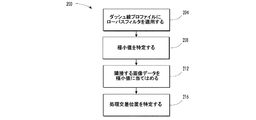
生成されたダッシュ線プロファイルをさらに分析して、ダッシュ線プロファイルにおける各ダッシュ線の中心に対応する処理交差位置を判定する(ブロック118)。図5に示すようなフィルタリングおよび補間プロセスを用いて、各ダッシュ線の中心を求めてもよい。図5において、プロセス200は、ダッシュ線プロファイルをローパスフィルタ核関数で畳み込み積分することにより開始する(ブロック204)。ローパスフィルタで畳み込み積分することは、走査線データをさらに平滑化する役割を果たし、画像データ中のダッシュ線による突然の突起は排除せず、ノイズによる突然の突起を排除する。一連の極小値の位置が、フィルタされた画像データ中で特定される(ブロック208)。図3の点により特定される各極小値は、光学検出器の解像度におけるフィルタされた画像データ中のダッシュ線の中心に対応する。ダッシュ線の中心をさらに明確に特定するために、極小値は、特定された極小値の両側における近傍ピクセルからのグレーレベル値に対して補間される(ブロック212)。この補間は、これら3つのデータ値を1つの曲線に当てはめ、より正確に極小値を特定することにより実行され得る。1つの補間方式では、2次曲線を用いて補間が行われる。当てはめられた曲線の極小値の処理交差位置は、テストパターン内のダッシュ線の中心として計算され記憶される(ブロック216)。ブロック208からブロック216の処理は、フィルタされた画像データにおいて特定された各極小値に対して実行される。
The generated dash line profile is further analyzed to determine a processing intersection location corresponding to the center of each dash line in the dash line profile (block 118). The center of each dash line may be determined using a filtering and interpolation process as shown in FIG. In FIG. 5,
図1のプロセス105は、検出されたダッシュ線指数を欠損ダッシュ線に対して訂正することにより継続する(ブロック122)。ダッシュ線は、様々な理由から、画像データから欠損し得る。しかし、ダッシュ線を印刷しようと意図したインクジェット排出器が、噴射信号に応答してダッシュ線を印刷することに失敗することにより、ダッシュ線が欠損することがしばしばある。欠損ダッシュ線の不在および特定は、テストパターンの既知の特性を用いることにより、獲得し得る。欠損ダッシュ線(単数または複数)の近傍では、例えば、期待されるよりも大きい距離が、検出されたダッシュ線の中心を離間する。ダッシュ線間の距離が、期待される距離よりも十分に広い余裕をもって大きい場合、1つまたは複数の排出器がテストパターンから欠損していると考えられる。用い得る他の特性は、ダッシュ線プロファイルにより示されるコントラストである。上述のように、ダッシュ線の中心は、インク色によって異る極小値に対応する。このように、このプロセスは、これらの異なるコントラスト値を用いて、欠損ダッシュ線の色を特定することが可能である。したがって、1つのエリア内のダッシュ線の数、そのエリア内のダッシュ線間の距離、およびそのエリア内のダッシュ線に対するコントラスト値を用いて、欠損ダッシュ線、および、その欠損ダッシュ線(単数または複数)を印刷したであろうインクジェット排出器を特定し得る。特定されたインクジェット排出器指数は、欠損ダッシュ線を考慮に入れて調節される。例えば、指数4および指数5のダッシュ線が欠損すると期待される、7つのダッシュ線のアレイにおいて、ダッシュ線3およびダッシュ線6の中心は、通常期待される距離の約3倍の距離で隔てられる。排出器6を不正確に排出器4として特定するのではなく、プロセス105は、欠損ダッシュ線を検出し、排出器6に対して正しい指数を割り当てる。検出されたダッシュ線を生成しないインクジェット排出器は、作動状態にないインクジェット排出器に対して補正するために、またはプリントヘッドが故障中であることを表示するために、別の指数が付されてもよい。
The
図2に見られるように、各プリントヘッド内のすべてのインクジェット排出器を含む完全なテストパターン配列は、テストパターン300に示される28個の列のように、複数の列を有する。テストパターンを受容する画像受容部材は、印刷領域内のインクステーション下で処理方向332に移動する。しかし、画像受容部材は、テストパターンに対するダッシュ線が形成されると、処理交差軸336に沿って漂動することもある。処理交差漂動エラーはテストパターン内の列間で蓄積し得る。その結果、異なる列内のダッシュ線の処理交差位置の測定値が不正確となり得る。
As can be seen in FIG. 2, the complete test pattern array, including all inkjet ejectors in each printhead, has multiple rows, such as the 28 rows shown in
プロセス105は、画像受容部材における漂動に起因する処理交差変位を測定し、補正する(ブロック126)。媒体漂動の大きさおよび方向を測定するために、1つの列のテストダッシュ線における各ダッシュ線の平均検出処理交差位置を、第1列のダッシュ線に対するダッシュ線の期待される平均位置と比較する。処理交差変位とは、測定された平均位置と期待される平均位置との差異である。すべての列のダッシュ線の位置を平均することにより、媒体漂動に起因するテストパターン撮像時のエラーと、より小さい群の排出器または単一のプリントヘッドにおける整列不良により生じ得るエラーとを区別することができる。 Process 105 measures and corrects the process cross displacement due to drift in the image receiving member (block 126). To measure the magnitude and direction of media drift, compare the average detection processing crossover position of each dash line in one column of test dash lines to the expected average position of the dash line relative to the dash line in the first column To do. The processing cross displacement is the difference between the measured average position and the expected average position. Distinguish between errors in test pattern imaging due to media drift and errors that can be caused by misalignment in a smaller group of ejectors or a single printhead by averaging the position of the dash lines in all columns can do.
処理交差媒体漂動により変位した列を有するテストパターンの1部分の1例が図6に示されている。テストパターン列404が画像受容部材上に形成され、後続の処理交差方向漂動が、列408および列412を含むすべての後続列に対して偏位を生じさせる。列408は、矢印416により示されるように、偏位している。処理交差偏位の計算は、列408内のダッシュ線が互いに対しては正確な位置にあるのに対し、列408内のダッシュ線の平均位置が期待される平均位置から偏位していることを判定する。こうして、列412等の後続の列は列408と整列する相対位置にある。
An example of a portion of a test pattern having columns displaced by process cross media drift is shown in FIG. A test pattern row 404 is formed on the image receiving member, and subsequent process cross direction drift causes deviations for all subsequent rows, including row 408 and
プロセス105は、ダッシュ線の検出された処理交差位置を逆の方向へと調節すること、および検出された偏位の大きさを調節することにより、媒体漂動の効果を無効化する。図6に示す例では、列408が矢印416の方向に30μmの処理交差偏位を有する場合、列408における各ダッシュ線の中心位置は、矢印416の逆方向に30μmだけ調節される。同一の訂正を列412等の後続の列に適用し、テストパターンの残りの部分に対して、処理交差漂動から導入されるエラーを取り除き得る。
ブロック114からブロック126に詳細に示される、印刷システムにおける各排出器に対する処理交差位置の判定により、処理方向に移動する画像受容部材を横断する各小滴の位置調節が可能となる。テストパターンにおける各ダッシュ線も処理方向の位置を占める。各排出器に対する絶対位置が判定される処理交差方向とは異なり、処理方向におけるプリントヘッド位置の判定はそれぞれのプリントヘッドの相対位置に基づく。相対位置が判定されるのは、画像受容部材が印刷領域において処理方向にプリントヘッドを通り過ぎ、そのために、各インク滴が射出されるタイミングによって処理方向に沿う任意の位置にプリントヘッドがインクを射出することができるためである。適切なタイミングは、複数のプリントヘッドからの小滴が平坦な列に整列することを可能にし、意図せずに過剰に印刷することを、または異なるプリントヘッドの噴射が早すぎるかまたは遅すぎるために列が不均一となることを、防ぐ。処理方向に整列したプリントヘッドは、意図的な過剰印刷を、または1つのプリントヘッドからのインク滴が異なるプリントヘッドからのインク滴と混合し新しい色を生成する重ね刷り(drop−on−drop)印刷を、可能にする。例えば、シアン・プリントヘッドからのインク滴が最初に射出され、その後、対応するイエロー・プリントヘッドからのインク滴がシアンのインク滴上に沈着すると、緑色に見えるインク塊が形成され得る。プリントヘッドの相対位置が既知である場合、印刷システムは、シアン排出器およびイエロー排出器の操作を調節して、重ね刷りの結果を生成し得る。
Determining the processing cross position for each ejector in the printing system, shown in detail in
見当合わせプロセス105は、処理方向における各プリントヘッドの相対位置を判定する(ブロック130)。図2のテストパターン300等のテストパターンを用いると、処理方向における、各プリントヘッドの、他のプリントヘッドに対する偏位を検出し得る。処理方向における各プリントヘッドの相対位置を判定するための1例としてのプロセス600が、図7に示されている。プロセス600は、図2のテストパターン300等のテストパターンにおいて単一のプリントヘッドに属するすべてのダッシュ線を特定することにより、開始する(ブロック604)。1つの例として、1つのペアとして示される2つのシアン・ダッシュ線304は、異なるシアン・プリントヘッドから出たもので、ダッシュ線ペア304がテストパターン300の全域で反復されている。テストパターンに存在するシアン・ダッシュ線の各ペアのうち最も左側にある検出されたダッシュ線は、1つの単一シアン・プリントヘッドに属し、最も右側のダッシュ線は別のシアン・プリントヘッドに属する。1つの単一プリントヘッドに属する各ダッシュ線が一度特定されると、各ダッシュ線の中心に最も近接する光学検出器のプロファイルは、例えば以前に図4の極小値の周辺での補間により特定されたように、処理方向において得られる(ブロック608)。各プロファイルを縁部検出核で畳み込み積分すると、処理方向における核ダッシュ線の頂部または底部が特定される。本明細書で用いられる「縁部検出核」とは、ダッシュ線と縁部検出核関数との畳み込み積分が処理方向において行内のダッシュ線の開始点において最小となるよう定義される関数を指す。縁部検出核で畳み込み積分を行うと、ダッシュ線の開始位置が光学検出器の下方にある画像受容部材の部分で生じる極小値が特定される。同様に、核ダッシュ線の端部分は、端縁部検出核で畳み込み積分を行うことにより特定し得る。端縁部核は、開始縁部核の逆関数である。同一の列のプリントヘッドインクジェットノズルにより生成されたダッシュ線を評価するためには、ダッシュ線の検出された縁部位置を平均して、個々の排出器における不整列の影響を低減する(ブロック612)。これらの列位置から、処理方向におけるプリントヘッドの中心が算出される(ブロック614)。他のプリントヘッドに対して、追加のプリントヘッドの処理方向位置を算出する必要がある場合(ブロック618)、プロセスは継続される(ブロック604)。さもなければ、図1に示す画像分析プロセスが継続する(ブロック622)。
一度、プリントヘッドの処理方向位置が判定されると、分析プロセス105は、印刷領域における異なるプリントヘッドの系列整列が特定される(ブロック134)。系列整列は、印刷領域において対応するプリントヘッドで使用される対応する排出器の処理交差整列であると定義される。図2に示すテストパターンにおいて、ライン340は、ブラック・ダッシュ線344A、イエロー・ダッシュ線344C、マゼンタ・ダッシュ線344E、およびシアン・ダッシュ線344Gの中心を含む単一の行を通り抜ける。これらダッシュ線のそれぞれは、CMYK色のそれぞれのプリントヘッドにおいて同一の目標位置を有するインクジェット排出器により生成される。1つの印刷行におけるダッシュ線は、ダッシュ線のそれぞれが同一の処理交差位置を有し、ライン340は各ダッシュ線の中心を通り抜けることができるため、系列整列状態にある。
Once the printhead processing direction position is determined, the
テストパターン300が、処理交差軸336に沿って整列するダッシュ線を示す間、1つの印刷行内の対応するインクジェット排出器に属するダッシュ線は、異なるプリントヘッドの処理交差位置の相違により整列不良であり得る。テストパターンのダッシュ線の検出された処理交差プロファイルを用いて、プロセス105は、基準プリントヘッドからの処理交差位置を、1つの印刷行における第2プリントヘッドの処理交差プロファイルと比較する。印刷行は、画像受容部材のほぼ同一部分と逆の処理方向に配列されたプリントヘッドに対応する。2つのプリントヘッドの間で不整列が存在する場合、プリントヘッドのインクジェット排出器の1部分は互いに重なり合う。系列整列を判定するために、1つのプリントヘッドを基準プリントヘッドとして選択し、基準ヘッドと他の任意のヘッドとの間で印刷された共通の組のノズルを特定する。例えば、各ヘッドが880個のノズルを有し、基準ヘッド上のノズル1は別のヘッドのノズル11と整列する場合、各プリントヘッドにおいて870個のノズルは重複領域に存在する。次に、測定されたノズル間隔と期待されるノズル間隔との差異が、重複領域における2つのプリントヘッドの各ペアのノズルに対して計算される。これらの測定された差異を平均すると、各印刷行における相対ヘッド偏位が得られる。印刷行における各ヘッドと基準ヘッドとの間の相対ヘッド偏位を調節し、相対ヘッド偏位の合計の平均値がゼロとなるようにする。相対ヘッド偏位は、印刷行における1つまたは複数のプリントヘッドの位置を変更することにより、調節される。
While the
プリントヘッドは、プリントヘッドに対してまたはプリントヘッドが取り付けられた取り付け部材に対して動作可能に接続された、電動モータ等の、アクチュエータを用いて、処理交差方向で調節され得る。これらのアクチュエータは、通常は、プロセス105を実行するよう構成された制御器により生成され得る制御信号に応答する電気機械的装置である。1つの実施形態において、各プリントヘッドは、独立したアクチュエータに対して動作可能に接続されてもよい。代替的な実施形態において、通常は単一のプリントヘッドバーに取り付けられた2つ以上のプリントヘッドのグループが、単一のアクチュエータを用いてプリントヘッド群を動かせるように、単一のアクチュエータに取り付けられてもよい。さらに、1つを除くすべてのプリントヘッドが独立した第2アクチュエータに機械的に接続され、この1つのプリントヘッドは、独立したアクチュエータを有さず、第1アクチュエータのみにより調節されてもよい。係る構成を用いると、第1アクチュエータが接続されたすべてのプリントヘッドを同時に調節し、第2独立アクチュエータが、それぞれのプリントヘッドにさらなる調節を提供することが可能となる。
The print head can be adjusted in the cross-process direction using an actuator, such as an electric motor, operatively connected to the print head or to a mounting member to which the print head is attached. These actuators are typically electromechanical devices that respond to control signals that can be generated by a controller configured to perform
処理交差方向における他の形のプリントヘッド整列は、ステッチ整列として知られる。ステッチ整列は、印刷アレイにおいて近接するプリントヘッド間の界面境界において生じる。多くのプリントヘッド構成は、印刷領域を通り抜ける画像受容部材の処理交差幅全体を覆うために、複数のプリントヘッドを単一アレイで異なる列上に配列する。複数のプリントヘッドは、処理交差方向において継ぎ目のないラインを形成するために、「ステッチ」される。例えば、図11に示すプリントヘッド1040の最も右側のインクジェット排出器は、プリントヘッド1036の最も左側のインクジェット排出器により射出されるインク滴に近接するインク滴を射出することができる。ステッチエラーは、同一色の隣接ヘッドの縁部ノズル間に間隔または重複が存在するときに生じる。 Another form of printhead alignment in the cross-process direction is known as stitch alignment. Stitch alignment occurs at the interface boundary between adjacent print heads in the print array. Many printhead configurations arrange multiple printheads on different columns in a single array to cover the entire processing cross-width of the image receiving member that passes through the print area. Multiple printheads are “stitched” to form a seamless line in the cross-process direction. For example, the rightmost inkjet ejector of printhead 1040 shown in FIG. 11 can eject ink drops that are close to the ink drops ejected by the leftmost inkjet ejector of printhead 1036. Stitch errors occur when there is a spacing or overlap between edge nozzles of adjacent heads of the same color.
図1に示すプロセス105において、Xステッチ整列は処理交差方向におけるダッシュ線位置測定値から計算される(ブロック138)。この整列の、1つの計算方法が図8に説明されている。プリントヘッド間の各ステッチ界面に対して、ステッチ界面の左側のプリントヘッドの16個のノズルのうち最も右側のノズルの処理交差位置がノズル指数に対してプロットされている。ノズル指数とは、各インクジェット排出器を一意的に特定するためにインクジェット排出器に割り当てられる番号である。例えば、880個のインクジェット排出器を有するプリントヘッドにおいて、インクジェット排出器は1から880の範囲の番号が一意的に割り当てられ得る。このグラフにおいて、ステッチ界面の右側のプリントヘッドの16個のノズルの処理交差位置は、ノズル指数に対してプロットされている。1本のラインが16個のノズルの各群を通り、界面へと外挿されている。2つの外挿されたラインの差異が、ステッチ変位と定義される。
In the
ステッチ変位の代替的な計算が図9に示されている。このプロセスにおいて、ステッチ界面の左側のプリントヘッド上の16個のノズルのうちの最も右側の平均位置904が計算され得、ステッチ界面の右側のプリントヘッド上の16個のノズルのうちの最も左側の平均位置908も計算され得る。これら平均位置間の期待される間隔は、16個のジェットに対応するはずである。測定された間隔912と期待される間隔との差異がステッチ変位である。ステッチ変位を算出するための2つのプロセスが説明されたが、他のプロセスも可能である。ステッチ方法の算出方法を、ステッチ界面の両側の各プリントヘッドにおける16個のノズルの群に関して説明してきたが、それ以外の個数のノズルも使用してよい。方法に関わりなく、ステッチ変位の計算はプリンタの各ステッチ界面に対して行われる(ブロック138、図1)。
An alternative calculation of stitch displacement is shown in FIG. In this process, the rightmost
動作中、図1に示す画像分析プロセス105は、通常動作の間に生じる漂動をプリントヘッドが補正するよう、規則的な周期で実行されてもよい。ユーザにより生成された、テストパターンを印刷し、プリンタのプリントヘッドを調節する信号に応答して、調節プロセスが行われてもよい。いくつかの実施形態において、本明細書で説明されたテストパターンの配列は、印刷プロセスの終了後に通常は廃棄される画像受容部材の部分上に印刷されてもよい。例えば、ウェブ印刷システムにおいて、ドキュメント間空白が、プリントヘッドの見当合わせのために用いられるテストパターン配列を含んでもよい。ドキュメント間空白は、ドキュメント領域間の狭い領域であり、この領域は、用紙の連続ウェブが個々のシートへと切断されるとき、切り落とされ得る。テストパターンの列は、切り落とされる個々の領域に分配されてもよい。1つまたは複数のテストパターンの列が、切り落とされる領域に印刷されてもよい。
In operation, the
Claims (4)
前記画像受容部材上の前記テストパターンの前記画像データにおける前記複数のダッシュ線列の各列にあるダッシュ線についての処理方向位置を特定することと、
前記処理交差方向における前記各ダッシュ線の中心を特定することと、
前記ダッシュ線列内の各ダッシュ線を形成したインクジェット排出器を特定することと、
前記画像受容部材によって反射された光に対する光学検出器の応答に対応する前記テストパターンの画像データの部分を、1つのダッシュ線列内のダッシュ線間の間隔に対応する周期を有するコサイン関数及びサイン関数で畳み込み積分し、各畳み込み積分の2乗を合計し、前記ダッシュ線の位置を前記畳み込み積分の2乗の和が閾値より大きくなる位置に対応するとして特定することで前記プリンタ内の各プリントヘッドについての処理交差位置を特定することと、
前記各プリントヘッドについての処理交差変位を特定することと、
同一色のインクを印刷する印字バーユニット内の隣接するプリントヘッド間の前記処理交差方向におけるステッチ変位を特定することと、
アクチュエータを操作して、少なくともいくつかの前記プリントヘッドを、前記特定された処理方向位置、処理交差変位、及び前記特定されたステッチ変位に対して、移動することと、
を含む、プリンタにより生成されたテストパターンの画像データを分析するための方法。 Image data of a test pattern having a plurality of dashed lines string as columns of dashes of multiple generated using an optical sensor, an image received by wherein each printhead of the plurality of print heads of the test pattern in the printer formed on the member, and wherein the plurality of printheads is to form the test pattern with at least one dash line in each column of the dashed row of the multiple,
And identifying a process direction position of the dashed line in each column of the multiple dashed row in the image data of the test pattern on said image receiving member,
Identifying the center of each dash line in the process crossing direction;
And identifying a pre inkjet ejectors forming the respective dashed lines of Kida Mesh lines in a column,
A portion of the image data of the test pattern corresponding to the response of the optical detector to the light reflected by the image receiving member is converted into a cosine function and a sine having a period corresponding to the spacing between the dash lines in one dash line row. Each print in the printer is convolved with a function, the squares of the respective convolution integrals are summed, and the position of the dash line is specified as corresponding to a position where the sum of the squares of the convolution integrals is greater than a threshold value. and identifying the cross-process position about the head,
And identifying the cross-process displacement with the each printhead,
Identifying stitch displacement in the cross-process direction between adjacent print heads in a print bar unit that prints the same color ink;
Manipulating an actuator to move at least some of the printheads relative to the identified process direction position, process cross displacement, and the identified stitch displacement;
A method for analyzing test pattern image data generated by a printer.
1つのダッシュ線列の全てのダッシュ線についてのプロファイルを生成することと、
処理交差方向における前記生成されたプロファイルの各ダッシュ線についての最小画像データ値と、前記最小画像データ値を生成した光学検出器とを特定することと、
前記特定された最小画像データ値と2つの画像データとに曲線を当てはめることと、ここで前記2つの画像データ値は前記最小画像データ値を生成した前記光学検出器の両側に配置される2つの光学検出器の応答に対応するものであり、
前記当てはめられた曲線の最小値を、前記最小画像データ値に対応する前記ダッシュ線の前記中心として特定することと、
をさらに含む、請求項1に記載の方法。 Identifying the center of each dash line is
Generating a profile about the entire dashes one dashed line column,
Identifying a minimum image data value for each dash line of the generated profile in a process cross direction and an optical detector that generated the minimum image data value;
Fitting a curve to the identified minimum image data value and the two image data, wherein the two image data values are arranged on two sides of the optical detector that generated the minimum image data value; It corresponds to the response of the optical detector,
Identifying the minimum value of the fitted curve as the center of the dash line corresponding to the minimum image data value;
The method of claim 1, further comprising:
前記ダッシュ線列内における欠損ダッシュ線の位置を特定することと、
前記欠損ダッシュ線に対してインクを射出するのに失敗したインクジェット排出器を特定することと、
を含む、方法。 The method of claim 1, and further to identify the position of the defect dashed before Kida Mesh lines in a column,
Identifying an inkjet ejector that has failed to eject ink against the missing dash line;
Including a method.
第1プリントヘッドの最も左側にあるインクジェット排出器における処理交差位置に、それぞれ最も左側にあるインクジェット排出器としての指数を関連付けることと、
前記処理交差方向において前記第1プリントヘッドの左側の次に最も近いプリントヘッドである第2プリントヘッドの最も右側にあるインクジェット排出器における処理交差位置に、それぞれ最も右側にあるインクジェット排出器としての指数に関連付けることと、
前記第1及び第2プリントヘッド間の界面における2つの関連付け指数間の処理交差位置変位を算出することによって前記ステッチ変位を特定することと、
を含む、請求項1に記載の方法。 Identifying the stitch displacement between adjacent printheads is
Associating an index as the leftmost inkjet ejector with each of the processing intersections in the leftmost inkjet ejector of the first printhead;
The index as the inkjet ejector on the rightmost side at the process intersection position in the inkjet ejector on the rightmost side of the second printhead, which is the next closest printhead on the left side of the first printhead in the process crossing direction. Associated with
Identifying the stitch displacement by calculating a process cross-position displacement between two association indices at the interface between the first and second printheads;
The method of claim 1 comprising:
Applications Claiming Priority (2)
| Application Number | Priority Date | Filing Date | Title |
|---|---|---|---|
| US12/754,735 US20110242187A1 (en) | 2010-04-06 | 2010-04-06 | Test Pattern Effective For Fine Registration Of Inkjet Printheads And Method Of Analysis Of Image Data Corresponding To The Test Pattern In An Inkjet Printer |
| US12/754,735 | 2010-04-06 |
Publications (3)
| Publication Number | Publication Date |
|---|---|
| JP2011218802A JP2011218802A (en) | 2011-11-04 |
| JP2011218802A5 JP2011218802A5 (en) | 2014-07-24 |
| JP5736207B2 true JP5736207B2 (en) | 2015-06-17 |
Family
ID=44709155
Family Applications (1)
| Application Number | Title | Priority Date | Filing Date |
|---|---|---|---|
| JP2011064766A Expired - Fee Related JP5736207B2 (en) | 2010-04-06 | 2011-03-23 | Test pattern effective for precise registration of inkjet print head and method of analyzing image data corresponding to test pattern of inkjet printer |
Country Status (2)
| Country | Link |
|---|---|
| US (2) | US20110242187A1 (en) |
| JP (1) | JP5736207B2 (en) |
Families Citing this family (36)
| Publication number | Priority date | Publication date | Assignee | Title |
|---|---|---|---|---|
| US8477165B2 (en) * | 2011-11-21 | 2013-07-02 | Electronics For Imaging, Inc. | Method and apparatus for thermal expansion based print head alignment |
| US8662625B2 (en) | 2012-02-08 | 2014-03-04 | Xerox Corporation | Method of printhead calibration between multiple printheads |
| EP2626209B1 (en) * | 2012-02-12 | 2018-04-11 | Baumer Inspection GmbH | Method and device for detecting malfunctions of nozzles of an ink-jet printer |
| US8646862B2 (en) * | 2012-02-28 | 2014-02-11 | Xerox Corporation | System and method for detection and compensation of inoperable inkjets in an inkjet printing apparatus |
| US8767233B2 (en) * | 2012-08-30 | 2014-07-01 | Eastman Kodak Company | Multi-resolution segmented image sensor |
| US8985725B2 (en) * | 2012-11-19 | 2015-03-24 | Xerox Corporation | Method and apparatus for alignment of a low contrast ink printhead in an inkjet printer |
| US8814305B2 (en) | 2012-11-26 | 2014-08-26 | Xerox Corporation | System and method for full-bleed and near full-bleed printing |
| US8767246B2 (en) | 2012-11-29 | 2014-07-01 | Xerox Corporation | System and method for page alignment in a printer |
| US8764149B1 (en) | 2013-01-17 | 2014-07-01 | Xerox Corporation | System and method for process direction registration of inkjets in a printer operating with a high speed image receiving surface |
| US8934133B2 (en) * | 2013-03-25 | 2015-01-13 | Eastman Kodak Company | High-speed multi-color printing |
| US9050840B2 (en) | 2013-09-05 | 2015-06-09 | Canon Kabushiki Kaisha | Printing apparatus and method for correcting printing position shift |
| US9067445B2 (en) * | 2013-09-17 | 2015-06-30 | Xerox Corporation | System and method of printhead calibration with reduced number of active inkjets |
| JP6287075B2 (en) * | 2013-11-01 | 2018-03-07 | セイコーエプソン株式会社 | Liquid ejector |
| US9415546B2 (en) | 2014-01-29 | 2016-08-16 | Xerox Corporation | System and method for controlling material drop volume in three dimensional object printing |
| GB2524230A (en) * | 2014-02-14 | 2015-09-23 | Asda Stores Ltd | Transaction processing system and transaction processing method |
| CN103984964B (en) * | 2014-06-05 | 2017-11-24 | 爱威科技股份有限公司 | A kind of test strips image-recognizing method and system |
| US10052823B2 (en) | 2014-10-08 | 2018-08-21 | Xerox Corporation | System and method for test pattern formation during three-dimensional object printing |
| US10291816B2 (en) | 2015-01-23 | 2019-05-14 | Xerox Corporation | System and method for identification and control of z-axis printhead position in a three-dimensional object printer |
| US9216603B1 (en) * | 2015-01-23 | 2015-12-22 | Xerox Corporation | System and method for generation of test patterns for measurement of printhead to substrate separation in a printer |
| EP3233504B1 (en) * | 2015-04-17 | 2020-09-09 | Hewlett-Packard Development Company, L.P. | Random wave mask generation |
| US9375962B1 (en) * | 2015-06-23 | 2016-06-28 | Xerox Corporation | System and method for identification of marks in printed test patterns |
| US9707785B2 (en) * | 2015-07-16 | 2017-07-18 | Xerox Corporation | System and method for analysis of compact printed test patterns |
| DE102017207304A1 (en) * | 2016-05-25 | 2017-11-30 | Heidelberger Druckmaschinen Ag | Method of detecting printing nozzle defects in an inkjet printing machine |
| US10946659B2 (en) | 2016-07-29 | 2021-03-16 | Hewlett-Packard Development Company, L.P. | Applying first and second weaving masks |
| DE102016117211A1 (en) * | 2016-09-13 | 2018-03-15 | Schmid Rhyner Ag | Method and device for ink-jet application on flat substrates |
| US9844961B1 (en) | 2016-10-27 | 2017-12-19 | Xerox Corporation | System and method for analysis of low-contrast ink test patterns in inkjet printers |
| US9956799B1 (en) | 2017-01-24 | 2018-05-01 | Ricoh Company, Ltd. | Test patterns for optimizing nozzle alignment of an ink-jet marking engine |
| US9908324B1 (en) | 2017-02-27 | 2018-03-06 | Eastman Kodak Company | Printing with overlapping printheads |
| US10545844B2 (en) * | 2017-09-29 | 2020-01-28 | Ricoh Company, Ltd. | Print verification system that reports defective printheads |
| JP7041498B2 (en) * | 2017-11-16 | 2022-03-24 | 株式会社Screenホールディングス | Printing equipment and printing method |
| KR102282482B1 (en) | 2018-02-06 | 2021-07-26 | 주식회사 엘지에너지솔루션 | Battery module and battery pack including the same |
| DE102018204312B3 (en) * | 2018-03-21 | 2019-02-21 | Heidelberger Druckmaschinen Ag | Threshold calculation with weighting |
| CN110682684B (en) * | 2018-07-06 | 2021-04-20 | 海德堡印刷机械股份公司 | Two-dimensional printing of nozzle test patterns |
| CN112693231B (en) * | 2019-10-23 | 2021-12-21 | 南通深南电路有限公司 | Ink jet monitoring system and ink jet monitoring method |
| US10919310B1 (en) * | 2019-12-05 | 2021-02-16 | Xerox Corporation | Methods for operating printhead inkjets to attenuate ink drying in the inkjets during printing operations |
| US11934712B2 (en) | 2021-11-17 | 2024-03-19 | Xerox Corporation | System and method for automatically diagnosing media handling defects in a printing device |
Family Cites Families (76)
| Publication number | Priority date | Publication date | Assignee | Title |
|---|---|---|---|---|
| US4675696A (en) | 1982-04-07 | 1987-06-23 | Canon Kabushiki Kaisha | Recording apparatus |
| US4401024A (en) | 1982-04-07 | 1983-08-30 | Milliken Research Corporation | Electronic patterning with registration control |
| USRE32967E (en) | 1982-11-24 | 1989-06-27 | Xerox Corporation | Web tracking system |
| US4887530A (en) | 1986-04-07 | 1989-12-19 | Quad/Tech, Inc. | Web registration control system |
| JP2950950B2 (en) | 1990-08-31 | 1999-09-20 | キヤノン株式会社 | Image recording device |
| US5325159A (en) | 1992-09-30 | 1994-06-28 | Phoenix Precision Graphics, Inc. | Printer in closed housing |
| US5451990A (en) | 1993-04-30 | 1995-09-19 | Hewlett-Packard Company | Reference pattern for use in aligning multiple inkjet cartridges |
| EP0622239B1 (en) | 1993-04-30 | 1998-08-26 | Hewlett-Packard Company | Multiple ink jet print cartridge alignment system |
| US5539498A (en) | 1993-06-18 | 1996-07-23 | Xeikon Nv | Paper receptor material conditioning apparatus and method |
| US5796414A (en) | 1996-03-25 | 1998-08-18 | Hewlett-Packard Company | Systems and method for establishing positional accuracy in two dimensions based on a sensor scan in one dimension |
| US6352331B1 (en) * | 1997-03-04 | 2002-03-05 | Hewlett-Packard Company | Detection of non-firing printhead nozzles by optical scanning of a test pattern |
| JP3310574B2 (en) | 1997-03-19 | 2002-08-05 | 富士通株式会社 | Image forming device |
| US6310637B1 (en) * | 1997-07-31 | 2001-10-30 | Seiko Epson Corporation | Method of printing test pattern and printing apparatus for the same |
| US6467867B1 (en) | 1997-09-03 | 2002-10-22 | Macdermid Acumen, Inc. | Method and apparatus for registration and color fidelity control in a multihead digital color print engine |
| US6109722A (en) * | 1997-11-17 | 2000-08-29 | Hewlett-Packard Company | Ink jet printing system with pen alignment and method |
| US6089693A (en) | 1998-01-08 | 2000-07-18 | Xerox Corporation | Pagewidth ink jet printer including multiple pass defective nozzle correction |
| US6072587A (en) | 1998-03-02 | 2000-06-06 | Accent Color Sciences, Inc. | Method of detecting position on a continuous print receiving elastic web |
| US6164750A (en) | 1998-03-04 | 2000-12-26 | Hewlett-Packard Company | Automated test pattern technique using accelerated sequence of color printing and optical scanning |
| US6196652B1 (en) | 1998-03-04 | 2001-03-06 | Hewlett-Packard Company | Scanning an inkjet test pattern for different calibration adjustments |
| US6275600B1 (en) | 1998-03-09 | 2001-08-14 | I.Data International, Inc. | Measuring image characteristics of output from a digital printer |
| US6049680A (en) | 1998-05-08 | 2000-04-11 | Agfa Gevaert N.V. | Apparatus for conditioning moisture content temperature of media |
| US6076915A (en) | 1998-08-03 | 2000-06-20 | Hewlett-Packard Company | Inkjet printhead calibration |
| US6266437B1 (en) | 1998-09-04 | 2001-07-24 | Sandia Corporation | Sequential detection of web defects |
| US5992973A (en) | 1998-10-20 | 1999-11-30 | Eastman Kodak Company | Ink jet printing registered color images |
| JP2000127360A (en) | 1998-10-23 | 2000-05-09 | Canon Inc | Recorder and print position correcting method |
| US6347856B1 (en) | 1999-03-05 | 2002-02-19 | Hewlett-Packard Company | Test pattern implementation for ink-jet printhead alignment |
| US6637853B1 (en) | 1999-07-01 | 2003-10-28 | Lexmark International, Inc. | Faulty nozzle detection in an ink jet printer by printing test patterns and scanning with a fixed optical sensor |
| US6847465B1 (en) | 2000-03-17 | 2005-01-25 | Hewlett-Packard Development Company, L.P. | Dynamic ink-jet print mode adjustment |
| US6655771B2 (en) * | 2000-06-27 | 2003-12-02 | Fuji Photo Film Co., Ltd. | Head position detecting method, recording head, image recording apparatus and storage medium |
| US6300968B1 (en) | 2000-11-02 | 2001-10-09 | Xerox Corporation | Color printing process direction color registration system with expanded chevrons |
| US6377758B1 (en) | 2000-11-06 | 2002-04-23 | Xerox Corporation | Method and system for analyzing imaging problems |
| US6466764B2 (en) | 2001-03-19 | 2002-10-15 | Hewlett-Packard Company | Electrophotographic printer employing heated presser rollers to precondition print media |
| US20020135629A1 (en) | 2001-03-26 | 2002-09-26 | Sam Sarmast | Pen alignment using a color sensor |
| US6770356B2 (en) | 2001-08-07 | 2004-08-03 | The Procter & Gamble Company | Fibers and webs capable of high speed solid state deformation |
| US6639669B2 (en) | 2001-09-10 | 2003-10-28 | Xerox Corporation | Diagnostics for color printer on-line spectrophotometer control system |
| JP2003219158A (en) | 2002-01-17 | 2003-07-31 | Ricoh Co Ltd | Image forming apparatus |
| JP2004074510A (en) | 2002-08-13 | 2004-03-11 | Canon Inc | Recorder and test pattern recording method |
| US6883892B2 (en) | 2002-10-31 | 2005-04-26 | Hewlett-Packard Development Company, L.P. | Printing apparatus calibration |
| KR100490427B1 (en) | 2003-02-14 | 2005-05-17 | 삼성전자주식회사 | Calibrating method of print alignment error |
| JP4567296B2 (en) | 2003-03-11 | 2010-10-20 | 株式会社リコー | Electrophotographic image position detection method and recording apparatus using the same |
| US7391525B2 (en) | 2003-03-14 | 2008-06-24 | Lexmark International, Inc. | Methods and systems to calibrate media indexing errors in a printing device |
| EP1473662B1 (en) | 2003-04-30 | 2009-08-26 | Hewlett-Packard Development Company, L.P. | Printing apparatus and method |
| JP4590841B2 (en) | 2003-08-07 | 2010-12-01 | 富士ゼロックス株式会社 | Image forming apparatus |
| US7073883B2 (en) | 2003-10-16 | 2006-07-11 | Eastman Kodak Company | Method of aligning inkjet nozzle banks for an inkjet printer |
| TWI274669B (en) | 2003-11-11 | 2007-03-01 | Ind Tech Res Inst | Method and apparatus for detecting faulty nozzles |
| US7090324B2 (en) * | 2003-12-19 | 2006-08-15 | Xerox Corporation | System and methods for compensating for streaks in images |
| JP4543703B2 (en) * | 2004-03-01 | 2010-09-15 | ソニー株式会社 | Printing apparatus, information processing apparatus, printing control method, program, test pattern data, and recording medium |
| JP2005246650A (en) * | 2004-03-01 | 2005-09-15 | Sony Corp | Printer, image processor, printing control method, program, test pattern data, and recording medium |
| CN101415555B (en) | 2004-07-10 | 2011-07-13 | 克劳佩塑料制品有限公司 | Method for correcting print repeat length variability in printed extensible materials and product |
| US20060072939A1 (en) | 2004-09-23 | 2006-04-06 | Kremer Karl H | Print correction for paper shrinkage |
| JP2006150961A (en) | 2004-11-25 | 2006-06-15 | Oce Technol Bv | Method of handling image receiving sheet, and heat melting inkjet printer adopting the method |
| JP2006150959A (en) | 2004-11-25 | 2006-06-15 | Oce Technol Bv | Printer with reel which supplies endless web of recording medium |
| JP2006151692A (en) | 2004-11-25 | 2006-06-15 | Oce Technol Bv | Printer having paper processing system |
| US7309118B2 (en) | 2004-11-30 | 2007-12-18 | Xerox Corporation | Systems and methods for reducing cross process direction registration errors of a printhead using a linear array sensor |
| US7552986B2 (en) | 2004-11-30 | 2009-06-30 | Xerox Corporation | Systems and methods for reducing process direction registration errors of a printhead using a linear array sensor |
| US7515305B2 (en) | 2005-03-18 | 2009-04-07 | Xerox Corporation | Systems and methods for measuring uniformity in images |
| US7254254B2 (en) | 2005-03-29 | 2007-08-07 | Brother Kogyo Kabushiki Kaisha | Method of evaluating quality of image and use thereof |
| US7380897B2 (en) | 2005-06-06 | 2008-06-03 | Lexmark International, Inc. | Method and apparatus for calibrating a printhead |
| US7647018B2 (en) | 2005-07-26 | 2010-01-12 | Xerox Corporation | Printing system |
| US7390073B2 (en) | 2005-07-29 | 2008-06-24 | Lexmark International, Inc. | Method and apparatus for performing alignment for printing with a printhead |
| US7549721B2 (en) | 2005-08-31 | 2009-06-23 | Seiko Epson Corporation | Printing method, printing system and method for determining correction value |
| US7630519B2 (en) | 2005-09-29 | 2009-12-08 | Xerox Corporation | Systems and methods for printing on pre-printed forms |
| KR101320849B1 (en) * | 2006-08-14 | 2013-10-21 | 삼성전자주식회사 | Array type inkjet printer and method for determinating nozzle condition thereof |
| US7607752B2 (en) | 2006-11-17 | 2009-10-27 | Hewlett-Packard Development Company, L.P. | Misfiring print nozzle compensation |
| US7665817B2 (en) | 2006-11-29 | 2010-02-23 | Xerox Corporation | Double reflex printing |
| US7630653B2 (en) | 2007-02-14 | 2009-12-08 | Xerox Corporation | System and method for in-line sensing and measuring image on paper registration in a printing device |
| JP4985255B2 (en) * | 2007-09-12 | 2012-07-25 | コニカミノルタIj株式会社 | Nozzle position adjustment chart creation method, nozzle position adjustment method, and image forming apparatus |
| US7686298B2 (en) | 2007-11-05 | 2010-03-30 | Xerox Corporation | Method and system for correcting lateral position error |
| JP2009241441A (en) * | 2008-03-31 | 2009-10-22 | Fujifilm Corp | Position detection device, image processor, position detection method and position detection program |
| US7878617B2 (en) | 2008-04-23 | 2011-02-01 | Xerox Corporation | Registration system for a web printer |
| ATE544605T1 (en) | 2008-05-28 | 2012-02-15 | Digital Information Ltd Ag | APPARATUS AND METHOD FOR PRODUCING PROOF PRINTS |
| US8200131B2 (en) | 2008-06-25 | 2012-06-12 | Xerox Corporation | Use of registration marks and a linear array sensor for in-situ raster output scanner scan line nonlinearity detection |
| US7837290B2 (en) | 2008-07-18 | 2010-11-23 | Xerox Corporation | Continuous web printing system alignment method |
| US8371674B2 (en) | 2010-09-08 | 2013-02-12 | Xerox Corporation | Method and printing system for implementing jet detection |
| KR101838671B1 (en) | 2010-12-20 | 2018-03-15 | 에스프린팅솔루션 주식회사 | Image forming apparatus and auto color registration method of the same |
| US8585173B2 (en) * | 2011-02-14 | 2013-11-19 | Xerox Corporation | Test pattern less perceptible to human observation and method of analysis of image data corresponding to the test pattern in an inkjet printer |
-
2010
- 2010-04-06 US US12/754,735 patent/US20110242187A1/en not_active Abandoned
-
2011
- 2011-03-23 JP JP2011064766A patent/JP5736207B2/en not_active Expired - Fee Related
-
2013
- 2013-09-09 US US14/021,408 patent/US8721033B2/en not_active Expired - Fee Related
Also Published As
| Publication number | Publication date |
|---|---|
| JP2011218802A (en) | 2011-11-04 |
| US20140009527A1 (en) | 2014-01-09 |
| US8721033B2 (en) | 2014-05-13 |
| US20110242187A1 (en) | 2011-10-06 |
Similar Documents
| Publication | Publication Date | Title |
|---|---|---|
| JP5736207B2 (en) | Test pattern effective for precise registration of inkjet print head and method of analyzing image data corresponding to test pattern of inkjet printer | |
| EP3300907B1 (en) | Image inspection method, image inspection device, program, and image recording system | |
| EP3305532B1 (en) | Image inspection device, image inspection method, program, and ink jet printing system | |
| US9227442B2 (en) | Printing apparatus and registration adjustment method | |
| US6942308B2 (en) | Compensation of lateral position changes in printing | |
| JP6569302B2 (en) | Image forming apparatus, method for adjusting image forming apparatus, and program | |
| JP5848978B2 (en) | A test pattern that is difficult to perceive by human observation and an image data analysis method that corresponds to the test pattern of an inkjet printer | |
| JP5670883B2 (en) | Method for adjusting a substrate and a print array in a printing apparatus | |
| JP2013147003A (en) | Method and apparatus for detecting discharge defect, image processing apparatus, program, and printing system | |
| US20060158476A1 (en) | Method and system for aligning ink ejecting elements in an image forming device | |
| KR101727754B1 (en) | System and method for correcting stitch error in a staggered printhead assembly | |
| US8727474B2 (en) | Inkjet printer and correction value acquisition method | |
| JP4756842B2 (en) | Print position adjusting method and printing apparatus | |
| US7891757B2 (en) | Marking element registration | |
| JP7147386B2 (en) | How to obtain the amount of impact deviation | |
| US20090237740A1 (en) | Method for Obtaining Correction Values and Liquid Ejecting Apparatus | |
| JP4270799B2 (en) | Image recording device | |
| JP4270780B2 (en) | Image recording device | |
| US20080143768A1 (en) | Adjustment of print arrays in a printing device | |
| CN110682684B (en) | Two-dimensional printing of nozzle test patterns | |
| Mizes et al. | Active alignment of print heads | |
| JP2020037209A (en) | Ink jet recorder, ink jet recording method, and program | |
| JP2006240060A (en) | Image correcting method |
Legal Events
| Date | Code | Title | Description |
|---|---|---|---|
| RD04 | Notification of resignation of power of attorney |
Free format text: JAPANESE INTERMEDIATE CODE: A7424 Effective date: 20130515 |
|
| A621 | Written request for application examination |
Free format text: JAPANESE INTERMEDIATE CODE: A621 Effective date: 20140320 |
|
| A521 | Written amendment |
Free format text: JAPANESE INTERMEDIATE CODE: A523 Effective date: 20140605 |
|
| A871 | Explanation of circumstances concerning accelerated examination |
Free format text: JAPANESE INTERMEDIATE CODE: A871 Effective date: 20140605 |
|
| A975 | Report on accelerated examination |
Free format text: JAPANESE INTERMEDIATE CODE: A971005 Effective date: 20140619 |
|
| A131 | Notification of reasons for refusal |
Free format text: JAPANESE INTERMEDIATE CODE: A131 Effective date: 20140902 |
|
| A521 | Written amendment |
Free format text: JAPANESE INTERMEDIATE CODE: A523 Effective date: 20141106 |
|
| A131 | Notification of reasons for refusal |
Free format text: JAPANESE INTERMEDIATE CODE: A131 Effective date: 20141209 |
|
| A521 | Written amendment |
Free format text: JAPANESE INTERMEDIATE CODE: A523 Effective date: 20150219 |
|
| TRDD | Decision of grant or rejection written | ||
| A01 | Written decision to grant a patent or to grant a registration (utility model) |
Free format text: JAPANESE INTERMEDIATE CODE: A01 Effective date: 20150324 |
|
| A61 | First payment of annual fees (during grant procedure) |
Free format text: JAPANESE INTERMEDIATE CODE: A61 Effective date: 20150420 |
|
| R150 | Certificate of patent or registration of utility model |
Ref document number: 5736207 Country of ref document: JP Free format text: JAPANESE INTERMEDIATE CODE: R150 |
|
| R250 | Receipt of annual fees |
Free format text: JAPANESE INTERMEDIATE CODE: R250 |
|
| R250 | Receipt of annual fees |
Free format text: JAPANESE INTERMEDIATE CODE: R250 |
|
| R250 | Receipt of annual fees |
Free format text: JAPANESE INTERMEDIATE CODE: R250 |
|
| LAPS | Cancellation because of no payment of annual fees |