JP5645031B2 - Data transmission / reception method - Google Patents
Data transmission / reception method Download PDFInfo
- Publication number
- JP5645031B2 JP5645031B2 JP2012255202A JP2012255202A JP5645031B2 JP 5645031 B2 JP5645031 B2 JP 5645031B2 JP 2012255202 A JP2012255202 A JP 2012255202A JP 2012255202 A JP2012255202 A JP 2012255202A JP 5645031 B2 JP5645031 B2 JP 5645031B2
- Authority
- JP
- Japan
- Prior art keywords
- data
- node
- transmission
- standby
- information
- Prior art date
- Legal status (The legal status is an assumption and is not a legal conclusion. Google has not performed a legal analysis and makes no representation as to the accuracy of the status listed.)
- Active
Links
- 230000005540 biological transmission Effects 0.000 title claims description 236
- 238000000034 method Methods 0.000 title claims description 54
- 230000000737 periodic effect Effects 0.000 claims description 21
- 230000004044 response Effects 0.000 description 41
- 239000000872 buffer Substances 0.000 description 15
- 239000002699 waste material Substances 0.000 description 12
- 238000010586 diagram Methods 0.000 description 9
- 238000001514 detection method Methods 0.000 description 7
- 230000002093 peripheral effect Effects 0.000 description 4
- 230000015572 biosynthetic process Effects 0.000 description 1
- 239000000284 extract Substances 0.000 description 1
- 230000004622 sleep time Effects 0.000 description 1
Images


Classifications
-
- H—ELECTRICITY
- H04—ELECTRIC COMMUNICATION TECHNIQUE
- H04L—TRANSMISSION OF DIGITAL INFORMATION, e.g. TELEGRAPHIC COMMUNICATION
- H04L12/00—Data switching networks
- H04L12/02—Details
- H04L12/12—Arrangements for remote connection or disconnection of substations or of equipment thereof
-
- H—ELECTRICITY
- H04—ELECTRIC COMMUNICATION TECHNIQUE
- H04L—TRANSMISSION OF DIGITAL INFORMATION, e.g. TELEGRAPHIC COMMUNICATION
- H04L12/00—Data switching networks
- H04L12/28—Data switching networks characterised by path configuration, e.g. LAN [Local Area Networks] or WAN [Wide Area Networks]
- H04L12/40—Bus networks
- H04L12/403—Bus networks with centralised control, e.g. polling
-
- H—ELECTRICITY
- H04—ELECTRIC COMMUNICATION TECHNIQUE
- H04L—TRANSMISSION OF DIGITAL INFORMATION, e.g. TELEGRAPHIC COMMUNICATION
- H04L12/00—Data switching networks
- H04L12/28—Data switching networks characterised by path configuration, e.g. LAN [Local Area Networks] or WAN [Wide Area Networks]
- H04L12/44—Star or tree networks
-
- H—ELECTRICITY
- H04—ELECTRIC COMMUNICATION TECHNIQUE
- H04L—TRANSMISSION OF DIGITAL INFORMATION, e.g. TELEGRAPHIC COMMUNICATION
- H04L41/00—Arrangements for maintenance, administration or management of data switching networks, e.g. of packet switching networks
- H04L41/12—Discovery or management of network topologies
-
- H—ELECTRICITY
- H04—ELECTRIC COMMUNICATION TECHNIQUE
- H04L—TRANSMISSION OF DIGITAL INFORMATION, e.g. TELEGRAPHIC COMMUNICATION
- H04L67/00—Network arrangements or protocols for supporting network services or applications
- H04L67/01—Protocols
- H04L67/10—Protocols in which an application is distributed across nodes in the network
- H04L67/104—Peer-to-peer [P2P] networks
-
- H—ELECTRICITY
- H04—ELECTRIC COMMUNICATION TECHNIQUE
- H04W—WIRELESS COMMUNICATION NETWORKS
- H04W28/00—Network traffic management; Network resource management
- H04W28/02—Traffic management, e.g. flow control or congestion control
- H04W28/04—Error control
-
- H—ELECTRICITY
- H04—ELECTRIC COMMUNICATION TECHNIQUE
- H04W—WIRELESS COMMUNICATION NETWORKS
- H04W28/00—Network traffic management; Network resource management
- H04W28/02—Traffic management, e.g. flow control or congestion control
- H04W28/06—Optimizing the usage of the radio link, e.g. header compression, information sizing, discarding information
- H04W28/065—Optimizing the usage of the radio link, e.g. header compression, information sizing, discarding information using assembly or disassembly of packets
-
- H—ELECTRICITY
- H04—ELECTRIC COMMUNICATION TECHNIQUE
- H04W—WIRELESS COMMUNICATION NETWORKS
- H04W52/00—Power management, e.g. TPC [Transmission Power Control], power saving or power classes
- H04W52/02—Power saving arrangements
-
- H—ELECTRICITY
- H04—ELECTRIC COMMUNICATION TECHNIQUE
- H04W—WIRELESS COMMUNICATION NETWORKS
- H04W52/00—Power management, e.g. TPC [Transmission Power Control], power saving or power classes
- H04W52/02—Power saving arrangements
- H04W52/0209—Power saving arrangements in terminal devices
- H04W52/0212—Power saving arrangements in terminal devices managed by the network, e.g. network or access point is master and terminal is slave
- H04W52/0216—Power saving arrangements in terminal devices managed by the network, e.g. network or access point is master and terminal is slave using a pre-established activity schedule, e.g. traffic indication frame
-
- H—ELECTRICITY
- H04—ELECTRIC COMMUNICATION TECHNIQUE
- H04W—WIRELESS COMMUNICATION NETWORKS
- H04W52/00—Power management, e.g. TPC [Transmission Power Control], power saving or power classes
- H04W52/02—Power saving arrangements
- H04W52/0209—Power saving arrangements in terminal devices
- H04W52/0212—Power saving arrangements in terminal devices managed by the network, e.g. network or access point is master and terminal is slave
- H04W52/0219—Power saving arrangements in terminal devices managed by the network, e.g. network or access point is master and terminal is slave where the power saving management affects multiple terminals
-
- H—ELECTRICITY
- H04—ELECTRIC COMMUNICATION TECHNIQUE
- H04W—WIRELESS COMMUNICATION NETWORKS
- H04W52/00—Power management, e.g. TPC [Transmission Power Control], power saving or power classes
- H04W52/02—Power saving arrangements
- H04W52/0209—Power saving arrangements in terminal devices
- H04W52/0225—Power saving arrangements in terminal devices using monitoring of external events, e.g. the presence of a signal
- H04W52/0229—Power saving arrangements in terminal devices using monitoring of external events, e.g. the presence of a signal where the received signal is a wanted signal
-
- H—ELECTRICITY
- H04—ELECTRIC COMMUNICATION TECHNIQUE
- H04W—WIRELESS COMMUNICATION NETWORKS
- H04W56/00—Synchronisation arrangements
-
- H—ELECTRICITY
- H04—ELECTRIC COMMUNICATION TECHNIQUE
- H04W—WIRELESS COMMUNICATION NETWORKS
- H04W68/00—User notification, e.g. alerting and paging, for incoming communication, change of service or the like
-
- H—ELECTRICITY
- H04—ELECTRIC COMMUNICATION TECHNIQUE
- H04W—WIRELESS COMMUNICATION NETWORKS
- H04W84/00—Network topologies
- H04W84/18—Self-organising networks, e.g. ad-hoc networks or sensor networks
-
- Y—GENERAL TAGGING OF NEW TECHNOLOGICAL DEVELOPMENTS; GENERAL TAGGING OF CROSS-SECTIONAL TECHNOLOGIES SPANNING OVER SEVERAL SECTIONS OF THE IPC; TECHNICAL SUBJECTS COVERED BY FORMER USPC CROSS-REFERENCE ART COLLECTIONS [XRACs] AND DIGESTS
- Y02—TECHNOLOGIES OR APPLICATIONS FOR MITIGATION OR ADAPTATION AGAINST CLIMATE CHANGE
- Y02D—CLIMATE CHANGE MITIGATION TECHNOLOGIES IN INFORMATION AND COMMUNICATION TECHNOLOGIES [ICT], I.E. INFORMATION AND COMMUNICATION TECHNOLOGIES AIMING AT THE REDUCTION OF THEIR OWN ENERGY USE
- Y02D30/00—Reducing energy consumption in communication networks
- Y02D30/70—Reducing energy consumption in communication networks in wireless communication networks
Description
本発明は、電力の浪費を効果的に抑制することのできるデータ送受信方法に関するものである。 The present invention relates to a data transmission / reception method capable of effectively suppressing power consumption.
ワイヤレスパーソナルエリアネットワークは、個人の作業環境にあるデバイスと、その周辺にあるデバイスとの相互接続を可能にする近距離ネットワークである。 A wireless personal area network is a short-range network that allows devices in a personal work environment to interconnect with devices in their vicinity.
近年、こうしたワイヤレスパーソナルエリアネットワークにおいて、小型で安価であり、かつ低出力のデジタル無線通信を行うことのできる、IEEE802.15.4の規格に準拠する通信デバイスが用いられている。 In recent years, in such wireless personal area networks, communication devices conforming to the IEEE802.15.4 standard that are small, inexpensive, and capable of performing low-power digital wireless communication have been used.
IEEE802.15.4の規格に準拠するネットワークは、大別すると、FFD(Full Function Device)とRFD(Reduced Function Device)の2種類のデバイスから構成されている。 A network conforming to the IEEE802.15.4 standard is roughly composed of two types of devices, FFD (Full Function Device) and RFD (Reduced Function Device).
FFDは、自らが属するパーソナルエリアネットワーク(PAN)に加入しようとする新規デバイスに対するPANへの加入承認機能および他のデバイスとの通信において用いられるスーパーフレームの定義機能を有する全機能搭載型デバイスである。このようなFFDのうち、各ネットワーク中に1つ存在し、ネットワーク全体のIDを決める機能を更に有するものを、PANコーディネータという。 The FFD is a full-featured device having a function for approving a PAN to a new device that intends to join a personal area network (PAN) to which the FFD belongs, and a function for defining a superframe used in communication with other devices. . Among such FFDs, one that exists in each network and further has a function of determining the ID of the entire network is called a PAN coordinator.
RFDは、FFDが有する上記加入承認機能およびスーパーフレームの定義機能を有していないデバイスであり、これらの機能を有していない以外は、FFDと同じ機能を有する機能制限型デバイスである。 The RFD is a device that does not have the above-described subscription approval function and superframe definition function that the FFD has, and is a function-restricted device that has the same functions as the FFD except that these functions are not provided.
図7は、FFDおよびRFDにより構成される従来のネットワークのトポロジーを示す模式図である。図7に示すように、こうしたネットワークのトポロジーとして、スター型ネットワーク(図7(A))、ピアツーピアネットワーク(図7(B))等のトポロジーが存在する。 FIG. 7 is a schematic diagram showing the topology of a conventional network configured by FFD and RFD. As shown in FIG. 7, as the topology of such a network, there are topologies such as a star network (FIG. 7A), a peer-to-peer network (FIG. 7B), and the like.
スター型ネットワークは、PANコーディネータおよび複数のFFDまたはRFDにより構成される。全てのデバイス間にはマスター・スレイブの関係が構築されている(特許文献1参照)。そして、上位に位置するマスターであるFFDから、下位にあるスレイブであるFDDまたはRFDに対し、定期的に同期用信号(ビーコン)が送信されることで、マスター・スレイブ間の同期が確立され、TDMA(Time Division Multiple Access)方式による情報の送受信が行われる。 The star network is composed of a PAN coordinator and a plurality of FFDs or RFDs. A master-slave relationship is established between all devices (see Patent Document 1). Then, a synchronization signal (beacon) is periodically transmitted from the FFD, which is the master located at the upper level, to the FDD or RFD, which is the slave at the lower level, thereby establishing synchronization between the master and the slave. Information is transmitted and received by a TDMA (Time Division Multiple Access) method.
一方、ピアツーピアネットワークは、PANコーディネータ、および複数のFFDまたはRFDにより構成される点は上述したスター型ネットワークと同様であるが、全てのデバイスは対等、すなわち、デバイス間にマスター・スレイブの関係が構築されないという点で異なっている。ピアツーピアネットワークを構成する各デバイス間では、CSMA(Carrier Sense Multiple Access)方式による情報の送受信が行われる。 On the other hand, the peer-to-peer network is similar to the star network described above in that it is composed of a PAN coordinator and a plurality of FFDs or RFDs, but all devices are equivalent, that is, a master-slave relationship is established between the devices. It is different in that it is not. Information is transmitted / received between the devices constituting the peer-to-peer network by a CSMA (Carrier Sense Multiple Access) method.
ところで、上述したいずれのネットワークトポロジーにおいては、FFDが通信網における通信のための時間同期、通信網への加入承認、離脱承認を行い、さらに、省電力のためのスリープ時間の設定までも一元的に管理している。そのため、通信網には少なくとも1台のFFDの存在が必須であり、このことが柔軟な通信網の形成を阻害する要因となっていた。 By the way, in any of the network topologies described above, the FFD performs time synchronization for communication in the communication network, approval for participation in the communication network, and approval for removal from the communication network, and also centralizes the setting of the sleep time for power saving. To manage. Therefore, it is essential for the communication network to have at least one FFD, and this has been a factor that hinders the formation of a flexible communication network.
また、FFDが存在しない場合、各デバイス間で予め同期を取ることは難しく、その状況下で情報の送受信を可能とするためには、従来各デバイスは常に待ち受け状態にある必要があるが、これでは電力の浪費を招いてしまう。 In addition, when there is no FFD, it is difficult to synchronize each device in advance, and in order to enable transmission and reception of information under the circumstances, each device conventionally needs to always be in a standby state. Then, waste of electric power is invited.
一方、各デバイスの電力の浪費を防止するため、所定の間隔で待ち受け状態となる、いわゆる間欠待ち受けを行う場合は、各デバイス間で間欠待ち受けの間隔や待ち受け時間にばらつきがあるため、情報の送受信を行えない場合があった。 On the other hand, in order to prevent the waste of power of each device, when performing so-called intermittent standby that enters a standby state at a predetermined interval, the interval and standby time of intermittent standby varies among devices, so that information is transmitted and received There was a case that could not be performed.
そこで、本発明は、上述した問題点に鑑みて案出されたものであり、FFDが存在しない場合にも情報の送受信を行うことができるとともに、電力の浪費を効果的に抑制することのできるデータ送受信方法を提供することを目的とする。 Therefore, the present invention has been devised in view of the above-described problems, and can transmit and receive information even when no FFD exists, and can effectively suppress waste of power. An object is to provide a data transmission / reception method.
本発明者は、上述した課題を解決するために、電力の浪費を効果的に抑制することのできるデータ送受信方法を発明した。 In order to solve the above-described problems, the present inventors have invented a data transmission / reception method capable of effectively suppressing power consumption.
本願請求項1に係るデータ送受信方法は、複数のノード間のデータ送受信方法であって、一のノードにおいて行われる、送信対象データのデータサイズについて、送信しうるデータサイズ以下か否かの判定を行う判定工程と、送信しうるデータサイズよりも大きい前記送信対象データを、送信しうるデータサイズ以下のデータサイズになる複数の中間データに分割する分割工程と、複数の前記中間データのそれぞれに分割ヘッダを付加し、複数の送信データを生成する送信データ生成工程と、複数の前記送信データを他のノードに送信する送信工程と、前記他のノードにおいて行われる、前記一のノードから送信された複数の前記送信データを受信する受信工程と、受信した複数の前記送信データについて、前記分割ヘッダの情報に基づき前記送信データを統合し、前記送信対象データを復元する復元工程と、を備えることを特徴とする。 The data transmission / reception method according to claim 1 of the present application is a data transmission / reception method between a plurality of nodes, and is performed in one node to determine whether or not the data size of transmission target data is equal to or smaller than a transmittable data size. A determination step to perform, a division step of dividing the transmission target data larger than the transmittable data size into a plurality of intermediate data having a data size equal to or smaller than the transmittable data size, and a plurality of the intermediate data A transmission data generation step of adding a header and generating a plurality of transmission data; a transmission step of transmitting the plurality of transmission data to another node; and the transmission from the one node performed in the other node A reception step for receiving a plurality of the transmission data, and a plurality of the transmission data received based on the information of the division header. Integrated transmission data, characterized by and a restoration step of restoring the transmitted data.
また、本願請求項2に係るデータ送受信方法は、請求項1に記載のデータ送受信方法であって、前記分割ヘッダには、前記中間データの並び順を規定する情報が含まれることを特徴とする。 A data transmission / reception method according to claim 2 of the present application is the data transmission / reception method according to claim 1, wherein the division header includes information defining an arrangement order of the intermediate data. .
また、本願請求項3に係るデータ送受信方法は、ノード間のデータ送受信方法であって、一のノードにおいて行われる、複数の送信対象データのそれぞれのデータサイズについて、送信しうるデータサイズ以下であるか否かの判定を行う判定工程と、データサイズが送信しうるデータサイズ以下である複数の前記送信対象データを、送信しうるデータサイズ以下になるように結合して送信データを生成する結合工程と、前記送信データを他のノードに送信する送信工程と、前記他のノードにおいて行われる、前記一のノードから送信された前記送信データを受信する受信工程と、受信した前記送信データについて、当該送信データに含まれる複数の前記送信対象データのヘッダ部の情報に基づき前記送信データを分割し複数の前記送信対象データを復元する復元工程と、を備えることを特徴とする。 In addition, the data transmission / reception method according to claim 3 of the present application is a data transmission / reception method between nodes, and the data size of each of a plurality of transmission target data performed in one node is equal to or less than a transmittable data size. A determining step for determining whether or not, and a combining step for generating a transmission data by combining a plurality of the transmission target data whose data size is equal to or less than a transmittable data size so as to be equal to or less than a transmittable data size A transmission step of transmitting the transmission data to another node, a reception step of receiving the transmission data transmitted from the one node performed in the other node, and the received transmission data, The transmission data is divided based on information of header parts of the plurality of transmission target data included in the transmission data, and a plurality of the transmission target data is divided. Characterized in that it comprises a restoring step of restoring the data, the.
本願請求項1に係るデータ送受信方法は、複数のノードが各々固有の間隔で周期的な待ち受けを行うノード間のデータ送受信方法であって、一のノードが、通信可能な他のノードを検出する検出工程と、前記一のノードが、データ送信タイミングを示す予告情報を所定の間隔を置いて複数回、前記他のノードの前記周期的な待ち受けの1つの周期に亘るように連続して前記他のノードに送信する連続送信工程と、前記周期的な待ち受け中に前記予告情報を受信した前記他のノードが、前記予告情報に示されている前記データ送信タイミングに従いデータを待ち受ける予告待受工程と、前記一のノードが、送信対象データのデータサイズについて、送信しうるデータサイズ以下か否かの判定を行う判定工程と、前記一のノードが、送信しうるデータサイズよりも大きい前記送信対象データを、送信しうるデータサイズ以下のデータサイズになる複数の中間データに分割する分割工程と、前記一のノードが、複数の前記中間データのそれぞれに分割ヘッダを付加し、複数の送信データを生成する送信データ生成工程と、前記一のノードが、前記他のノードに、前記予告情報の前記データ送信タイミングに従い複数の前記送信データを送信する予告送信工程と、前記他のノードが、前記予告データ送信タイミングに従い前記一のノードから送信された前記送信データを受信する予告受信工程と、前記他のノードが、受信した複数の前記送信データについて、前記分割ヘッダの情報に基づき統合し、前記送信対象データを復元する復元工程と、を備えることを特徴とする。 A data transmission / reception method according to claim 1 of the present application is a data transmission / reception method between nodes in which a plurality of nodes periodically waits at a specific interval, and one node detects other nodes that can communicate with each other. A step of detecting, and the one node continuously providing the notice information indicating the data transmission timing a plurality of times at predetermined intervals so as to cover one period of the periodic standby of the other node. A continuous transmission step of transmitting to the other node, and a standby standby step of waiting for data in accordance with the data transmission timing indicated by the previous information, in which the other node that has received the advance notice information during the periodical waiting is provided. A determination step of determining whether or not the data size of the transmission target data is equal to or smaller than a data size that can be transmitted; and a data that can be transmitted by the one node. A division step of dividing the transmission target data larger than the data size into a plurality of intermediate data having a data size equal to or smaller than a transmittable data size, and the one node adds a division header to each of the plurality of intermediate data A transmission data generation step of generating a plurality of transmission data, and the one node transmitting a plurality of the transmission data to the other node according to the data transmission timing of the notification information, A notice receiving step in which another node receives the transmission data transmitted from the one node according to the notice data transmission timing, and information on the division header for the plurality of transmission data received by the other node. And a restoration step of restoring the transmission target data.
また、本願請求項2に係るデータ送受信方法は、複数のノードが各々固有の間隔で周期的な待ち受けを行うノード間のデータ送受信方法であって、一のノードが、通信可能な他のノードを検出する検出工程と、前記一のノードが、前記他のノードが前記周期的な待ち受けを行うタイミングを示す待受情報を要求する待受情報要求を、所定の間隔を置いて複数回、前記他のノードの前記周期的な待ち受けの1つの周期に亘るように連続して前記他のノードに送信する連続送信工程と、前記一のノードが、複数回の前記待受情報要求の送信にそれぞれ連続して、前記他のノードからの待受情報の待ち受けを行う受信待受工程と、前記一のノードからの前記待受情報要求を受信した前記他のノードが、前記待受情報を前記一のノードに送信する待受情報送信工程と、前記一のノードが、前記他のノードから送信された前記待受情報を受信する待受情報受信工程と、前記一のノードが、送信対象データのデータサイズについて、送信しうるデータサイズ以下か否かの判定を行う判定工程と、前記一のノードが、送信しうるデータサイズよりも大きい前記送信対象データを、送信しうるデータサイズ以下のデータサイズになる複数の中間データに分割する分割工程と、前記一のノードが、複数の前記中間データのそれぞれに分割ヘッダを付加し、複数の送信データを生成する送信データ生成工程と、前記一のノードが、前記他のノードに、受信した前記待受情報に示されている前記タイミングに従い複数の前記送信データの送信を行うデータ送信工程と、前記他のノードが、前記周期的な待ち受け中に前記一のノードから送信された複数の前記送信データを受信するデータ受信工程と、前記他のノードが、受信した複数の前記送信データについて、前記分割ヘッダの情報に基づき前記送信データを統合し、前記送信対象データを復元する復元工程と、を備えることを特徴とする。 In addition, the data transmission / reception method according to claim 2 of the present application is a data transmission / reception method between nodes in which a plurality of nodes periodically waits at a specific interval, and one node can communicate with other nodes that can communicate with each other. A detection step for detecting, and a standby information request for requesting standby information indicating a timing at which the one node performs the periodic standby by the other node, at a predetermined interval, and the other node A continuous transmission step of continuously transmitting to the other nodes over one period of the periodic standby of the node, and the one node continuously transmitting the standby information request a plurality of times. A reception standby step of waiting for standby information from the other node, and the other node receiving the standby information request from the one node receives the standby information from the one node. Standby to send to the node The information transmission step, the standby information receiving step in which the one node receives the standby information transmitted from the other node, and the one node can transmit the data size of the transmission target data. A determination step of determining whether the data size is equal to or smaller than the data size, and the transmission target data larger than the data size that can be transmitted by the one node into a plurality of intermediate data having a data size equal to or smaller than the data size that can be transmitted A dividing step of dividing, a transmission node generating step of generating a plurality of transmission data by adding a division header to each of the plurality of intermediate data, and the one node being connected to the other node A data transmission step of transmitting a plurality of the transmission data according to the timing indicated in the received standby information, and the other node A data reception step of receiving a plurality of the transmission data transmitted from the one node during the transmission, and the other node, for the plurality of transmission data received, the transmission data based on the information of the division header And a restoration step of integrating and restoring the transmission target data.
本願請求項1に係る発明によれば、下位層が送信しうるデータサイズが小さいときに、大きなデータを分割して送信することにより、生成データのサイズに関わらず、データ送信をスムーズかつ確実に行うことができるとともに、不必要な再送信処理を繰り返すことが無くなり、電力の浪費を効果的に抑制することができる。また、FFDが存在せず、各ノード間で同期が確立されていない状況下においても、情報の送受信を行うことができる。さらに、各ノードは常時待ち受けを行わず、間欠的に待ち受けを行うとともに、データの送受信時にもデータ送信タイミングに示した時間帯においてのみ起動し、データの待ち受け、送信及び受信を行えばよいため、電力の浪費を効果的に抑制することができる。 According to the invention of claim 1 of the present application, when the data size that can be transmitted by the lower layer is small, large data is divided and transmitted so that data transmission can be performed smoothly and reliably regardless of the size of the generated data. This can be performed, and unnecessary retransmission processing is not repeated, so that waste of power can be effectively suppressed. In addition, information can be transmitted and received even in a situation where there is no FFD and synchronization is not established between the nodes. In addition, each node does not always wait, intermittently waits, and only activates in the time zone indicated in the data transmission timing at the time of data transmission and reception, because it is only necessary to wait for data, transmit and receive data, The waste of electric power can be effectively suppressed.
本願請求項2に係る発明によれば、下位層が送信しうるデータサイズが小さいときに、大きなデータを分割して送信することにより、生成データのサイズに関わらず、データ送信をスムーズかつ確実に行うことができるとともに、不必要な再送信処理を繰り返すことが無くなり、電力の浪費を効果的に抑制することができる。また、FFDが存在せず、各ノード間で同期が確立されていない状況下においても、情報の送受信を行うことができる。さらに、各ノードは常時待ち受けを行わず、間欠的に待ち受けを行うとともに、データの送受信時にもデータ受信タイミングに示した時間帯においてのみ起動し、データの待ち受け、送信及び受信を行う。そのため、電力の浪費を効果的に抑制することができる。 According to the invention of claim 2 of the present application, when the data size that can be transmitted by the lower layer is small, large data is divided and transmitted, so that data transmission can be performed smoothly and reliably regardless of the size of the generated data. This can be performed, and unnecessary retransmission processing is not repeated, so that waste of power can be effectively suppressed. In addition, information can be transmitted and received even in a situation where there is no FFD and synchronization is not established between the nodes. Furthermore, each node does not always wait, but intermittently waits, and is activated only during the time period indicated in the data reception timing during data transmission / reception, and waits for data transmission and reception. Therefore, waste of electric power can be effectively suppressed.
以下、本発明に係るデータ送受信方法の各実施形態ついて詳細に説明する。 Hereinafter, embodiments of the data transmission / reception method according to the present invention will be described in detail.
<第1実施形態>
まず、本発明の第1実施形態に係るデータ送受信方法について説明する。
<First Embodiment>
First, the data transmission / reception method according to the first embodiment of the present invention will be described.
図1は、実施形態に係るデータ送受信方法におけるノードの構造を示す図である。ノード1は、無線部2、通信制御部3および上位層処理部4を備えて構成されている。なお、ノードとは、FFDとRFDとを含めたデータの発信、中継等、データの送受信を行うデバイスの総称である。 FIG. 1 is a diagram illustrating a node structure in the data transmission / reception method according to the embodiment. The node 1 includes a radio unit 2, a communication control unit 3, and an upper layer processing unit 4. Note that a node is a generic name for devices that transmit and receive data, such as data transmission and relay including FFD and RFD.
無線部2は、受信用アンテナ21を介してデータを受信する受信部22、送信用アンテナ23を介してデータを送信する送信部24、各種データをバッファするメインバッファ25、およびメインバッファ25と送信部24との間に設けられ、メインバッファ25から送信部24に送られる送信データをバッファする送信バッファ26を有している。
The radio unit 2 includes a receiving
通信制御部3は、無線部2と上位層処理部4との間に設けられ、無線部2による無線通信全体を制御する。通信制御部3は、受信用アンテナ21を介して受信部22が受信したデータに含まれるペイロードを抽出し、当該ペイロードのそれぞれについて行われるべき処理を判定し、当該判定結果に応じて各ペイロードをメインバッファ25や上位層処理部4に送信する。
The communication control unit 3 is provided between the radio unit 2 and the upper layer processing unit 4 and controls the entire radio communication by the radio unit 2. The communication control unit 3 extracts the payload included in the data received by the
上位層処理部4は、受信したデータに各種処理を加えるとともに、新たなペイロード等、データの送受信に関する各種データの生成を行う。 The upper layer processing unit 4 applies various processes to the received data and generates various data related to data transmission / reception such as a new payload.
次に、上述したノード1により行われる待ち受けの様子を説明する。図2は、本発明の各実施形態に係るデータ送受信方法において、各ノード1が周期的に待ち受けを行う様子を示す図である。なお、図2に示す各ノードの周期的な待ち受けは、後述する他の実施形態においても行われるものである。 Next, the standby state performed by the node 1 described above will be described. FIG. 2 is a diagram illustrating a state in which each node 1 periodically waits in the data transmission / reception method according to each embodiment of the present invention. Note that the periodic standby of each node shown in FIG. 2 is also performed in other embodiments described later.
図2に示すように、各ノードは、各々固有の待受期間および固有の間隔で、周期的な待ち受けを行っている。こうして各ノードが常に待受状態、すなわち常に電源が投入されている状態ではなく、間欠的に待受状態になることで、電力の浪費を防止することができる。 As shown in FIG. 2, each node waits periodically with a unique standby period and a specific interval. In this way, each node is not always in a standby state, that is, not always in a power-on state, but intermittently enters a standby state, thereby preventing waste of power.
なお、図2に示すように、各ノード間で同期は確立されていないが、本発明に係るデータ送受信方法は、こうした状況下においてもノード間でのデータの送受信を可能とする。 As shown in FIG. 2, although synchronization is not established between the nodes, the data transmission / reception method according to the present invention enables data transmission / reception between the nodes even under such circumstances.
次に、こうしたノードによる周辺のノードの検出方法について説明する。図3は、本実施形態に係るデータ送受信方法において、周辺のノードの検出が行われる様子を示す図である。 Next, a method for detecting neighboring nodes using such nodes will be described. FIG. 3 is a diagram illustrating a manner in which peripheral nodes are detected in the data transmission / reception method according to the present embodiment.
まず、周辺のノードにデータを送信するため、周辺にある通信可能なノードの検出を行うノード(以下「要求ノード」という。)は、採用しているデータの変調方式やデータの受信待ち受けを行うタイミング等、要求ノードの固有の情報(以下、「ノード情報」という。)の送信と、データの受信待ち受けと、を所定の間隔で繰り返す(ステップS1)。以下、このノード情報の送信とデータの受信待ち受けを合わせてディスカバリー動作という。 First, in order to transmit data to a peripheral node, a node that detects a communicable node in the vicinity (hereinafter referred to as a “request node”) waits for a data modulation method and data reception employed. Transmission of information unique to the request node (hereinafter referred to as “node information”) such as timing and data reception standby are repeated at predetermined intervals (step S1). Hereinafter, the node information transmission and the data reception standby are collectively referred to as a discovery operation.
次に、要求ノードの周辺にある、自らに固有の間隔で周期的な待ち受けを行っている別のノードは、この周期的な待ち受け中に要求ノードから送信されたノード情報を受信する(ステップS2)。なお、図2には、要求ノードの周辺に2つのノード(以下、「応答ノード1、2」という。)が存在し、これら2つの応答ノード1、2が要求ノードからのノード情報を受信する。 Next, another node in the vicinity of the request node and periodically waiting at its own interval receives the node information transmitted from the request node during this periodic waiting (step S2). ). In FIG. 2, there are two nodes (hereinafter referred to as “response nodes 1 and 2”) around the request node, and these two response nodes 1 and 2 receive node information from the request node. .
ここで、応答ノードと要求ノード1、2との間には同期は確立されていないが、要求ノードが定期的に行うディスカバリー動作においてノード情報を繰り返して送信する一方、応答ノード1、2が定期的に待ち受けを繰り返すことにより、要求ノードからのノード情報の送信タイミングと、応答ノード1、2の待ち受けのタイミングが一致する場合がある。こうして両タイミングの一致が生じることで、同期が確立していないノード間においても、情報の送受信を行うことができる。 Here, although synchronization is not established between the response node and the request nodes 1 and 2, node information is repeatedly transmitted in a discovery operation periodically performed by the request node, while the response nodes 1 and 2 If the standby is repeated repeatedly, the transmission timing of the node information from the requesting node may coincide with the standby timing of the response nodes 1 and 2. As a result of the coincidence of both timings, information can be transmitted and received even between nodes where synchronization is not established.
次に、要求ノードから送信されたノード情報を受信した応答ノード1、2は、それぞれ自らのノード情報を要求ノードに対して送信するとともに、要求ノードは、応答ノード1、2から送信されたノード情報を上述したディスカバリー動作に含まれる受信待ち受け中に受信する(ステップS3)。 Next, the response nodes 1 and 2 having received the node information transmitted from the request node transmit their own node information to the request node, and the request node is a node transmitted from the response nodes 1 and 2. Information is received while waiting for reception included in the above-described discovery operation (step S3).
こうして要求ノードと応答ノード1、2との間でノード情報の交換が行われることで、要求ノードによる応答ノード1、2の検出が完了する。そして、以後、要求ノードと応答ノード1、2との間で情報の送受信が行われる場合には、各ノード間に適したデータの変調方式等が、ノード情報を基に選択される。 Thus, the exchange of node information between the request node and the response nodes 1 and 2 completes the detection of the response nodes 1 and 2 by the request node. Thereafter, when information is transmitted and received between the request node and the response nodes 1 and 2, a data modulation method suitable for each node is selected based on the node information.
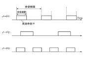
次に、ノード検出後の要求ノードと応答ノードとの間における、実際のデータの送受信について説明する。図4は、本発明の第1実施形態に係るデータ送受信方法におけるノード間のデータ送受信の様子を示す図である。 Next, actual data transmission / reception between the request node and the response node after node detection will be described. FIG. 4 is a diagram illustrating a state of data transmission / reception between nodes in the data transmission / reception method according to the first embodiment of the present invention.
まず、要求ノードは、今から何秒後にデータを送信する等、データ送信タイミングを示す予告情報を、所定の間隔を置いて複数回連続して応答ノードに送信する(ステップS11)。このとき、予告情報の連続送信回数は、応答ノードの周期的な待ち受けの1つの周期に亘る程度の十分な回数行われることが好ましい。これは、応答ノードが予告情報を受信する確立を高めるためであり、上述したように予告情報の連続送信が1つの周期に亘る回数行われた場合には、応答ノードは予告情報を確実に受信することができるようになる。 First, the request node transmits notice information indicating the data transmission timing to the response node continuously several times at predetermined intervals, such as how many seconds from now on, for example, data transmission (step S11). At this time, it is preferable that the number of continuous transmissions of the advance notice information is performed a sufficient number of times over one period of periodic waiting of the response node. This is to increase the probability that the response node receives the advance notice information. As described above, if the advance transmission of the advance notice information is performed a number of times in one cycle, the response node reliably receives the advance notice information. Will be able to.
ここで、各予告情報中に含まれるデータ送信タイミングは、最初に送信された予告情報中のものから順に短いものとなっていく。例えば、最初に送信された予告情報の送信開始時点を基準とし、当該最初の予告情報中に含まれるデータ送信タイミングが「現時点から10秒後」であり、0.5秒後に予告情報の送信が終了し、0.5秒の間隔を空けた後、1秒後に次の予告情報の送信が開始される場合には、当該次の予告情報中に含まれるデータ送信タイミングは「現時点から9秒後」となる。 Here, the data transmission timing included in each piece of advance notice information becomes shorter in order from the one in the notice information transmitted first. For example, on the basis of the transmission start time of the first notice information transmitted, the data transmission timing included in the first notice information is “10 seconds after the current time”, and the notice information is transmitted after 0.5 seconds. When the transmission of the next notice information is started after one second after the interval of 0.5 seconds, the data transmission timing included in the next notice information is “9 seconds after the current time. "
次に、上述したように固有の間隔で周期的な待ち受けを行っている応答ノードは、要求ノードから送信された予告情報を受信する(ステップS12)。上述したように、予告情報の連続送信回数が応答ノードの周期的な待ち受けの1つの周期に亘る程度の回数行われることで、応答ノードは予告情報を確実に受信することができるため好ましい。 Next, the response node that periodically waits at a specific interval as described above receives the advance notice information transmitted from the request node (step S12). As described above, it is preferable that the number of continuous transmissions of the notice information is performed as many times as one period of the periodic standby of the response node, so that the response node can reliably receive the notice information.
次に、予告情報を受信した応答ノードは、受信した予告情報に示されているデータ送信タイミングに従い、データの待ち受けを行うとともに、送信ノードは、予告情報に示したデータ送信タイミングに従いデータ送信を行い、応答ノードが当該データを受信する(ステップS13)。こうして一連のデータの送受信が完了する。 Next, the response node that has received the advance notice information waits for data according to the data transmission timing indicated in the received advance notice information, and the transmission node performs data transmission according to the data transmission timing indicated in the advance notice information. The response node receives the data (step S13). Thus, transmission / reception of a series of data is completed.
上述した本実施形態に係るデータ送受信方法によると、FFDが存在せず、各ノード1間で同期が確立されていない状況下においても、情報の送受信を行うことができる。 According to the data transmission / reception method according to the present embodiment described above, information can be transmitted / received even in a situation where no FFD exists and synchronization is not established between the nodes 1.
また、各ノード1は常時待ち受けを行わず、間欠的に待ち受けを行うとともに、データの送受信時にもデータ送信タイミングに示した時間帯においてのみ起動し、データの待ち受け、送信及び受信を行えばよいため、電力の浪費を効果的に抑制することができる。 In addition, each node 1 does not always wait, but waits intermittently, and is activated only during the time indicated in the data transmission timing during data transmission / reception, so that data can be waited, transmitted, and received. The waste of electric power can be effectively suppressed.
<第2実施形態>
次に、本発明の第2実施形態に係るデータ送受信方法について説明する。
Second Embodiment
Next, a data transmission / reception method according to the second embodiment of the present invention will be described.
本実施形態に係るデータ送受信方法においても、図2で示したように、各ノード1は、第1実施形態と同様に各々固有の待受期間および固有の間隔で、周期的な待ち受けを行っている。そして、本実施形態における周辺のノード1の検出方法は上述した第1実施形態におけるものと同様にして行われ、要求ノードと応答ノードが発生する。 Also in the data transmission / reception method according to the present embodiment, as shown in FIG. 2, each node 1 performs periodic standby with a specific standby period and a specific interval, as in the first embodiment. Yes. And the detection method of the surrounding node 1 in this embodiment is performed like the thing in 1st Embodiment mentioned above, and a request | requirement node and a response node generate | occur | produce.
次に、周辺ノードの検出後に行われるデータの送受信の様子について以下に説明する。図5は、本発明の第2実施形態に係るデータ送受信方法におけるノード1間のデータ送受信の様子を示す図である。 Next, the state of data transmission / reception performed after detection of peripheral nodes will be described below. FIG. 5 is a diagram illustrating a state of data transmission / reception between nodes 1 in the data transmission / reception method according to the second embodiment of the present invention.
まず、応答ノードは、周期的な待ち受けの前に連続して、自らの周期的な待ち受けを行うタイミングを示す待受情報を要求ノードに送信する(ステップS21)。待受情報は、周期的な待ち受けに連続して送信されることで、周期的な待ち受けと同じ周期で繰り返し送信されることになる。 First, the response node continuously transmits standby information indicating the timing of performing its own periodic standby to the requesting node before the periodic standby (step S21). The standby information is transmitted repeatedly in the same cycle as the periodic standby by continuously transmitting the periodic standby.
一方、要求ノードは、要求ノードに送信するデータの生成を行うと同時に、待ち受けを行う(ステップS22)。 On the other hand, the request node waits at the same time as generating data to be transmitted to the request node (step S22).
そして、この待ち受けの最中に要求ノードが応答ノードから送信される待受情報を受信すると、要求ノードは、受信した待受情報に示されている応答ノードの、周期的な待ち受けを行うタイミングに従い、応答ノードに対し、生成したデータを送信するとともに、応答ノードは当該データを受信する(ステップS23)。 Then, when the request node receives the standby information transmitted from the response node during the standby, the request node follows the timing of performing the periodic standby of the response node indicated in the received standby information. The generated data is transmitted to the response node, and the response node receives the data (step S23).
このとき、要求ノードから送信されたデータは、応答ノードの周期的な待ち受け中に送信されることになるため、応答ノードはこの周期的な待ち受け中に当該データを受信することになる。こうして一連のデータの送受信が完了する。 At this time, since the data transmitted from the request node is transmitted during the periodical waiting of the response node, the response node receives the data during the periodical waiting. Thus, transmission / reception of a series of data is completed.
上述した本実施形態に係るデータ送受信方法によると、FFDが存在せず、各ノード1間で同期が確立されていない状況下においても、情報の送受信を行うことができる。 According to the data transmission / reception method according to the present embodiment described above, information can be transmitted / received even in a situation where no FFD exists and synchronization is not established between the nodes 1.
また、各ノード1は常時待ち受けを行わず、間欠的に待ち受けを行うとともに、データの送受信時にもデータ受信タイミングに示した時間帯においてのみ起動し、データの待ち受け、送信及び受信を行う。そのため、電力の浪費を効果的に抑制することができる。 In addition, each node 1 does not always wait, but intermittently waits, and is activated only during the time indicated by the data reception timing during data transmission / reception, and waits for, transmits, and receives data. Therefore, waste of electric power can be effectively suppressed.
<第3実施形態>
次に、本発明の第3実施形態に係るデータ送受信方法について説明する。
<Third Embodiment>
Next, a data transmission / reception method according to the third embodiment of the present invention will be described.
本実施形態に係るデータ送受信方法においても、図2で示したように、各ノード1は、第1実施形態と同様に各々固有の待受期間および固有の間隔で、周期的な待ち受けを行っている。そして、本実施形態における周辺のノード1の検出方法は上述した第1実施形態におけるものと同様にして行われ、要求ノードと応答ノードが発生する。 Also in the data transmission / reception method according to the present embodiment, as shown in FIG. 2, each node 1 performs periodic standby with a specific standby period and a specific interval, as in the first embodiment. Yes. And the detection method of the surrounding node 1 in this embodiment is performed like the thing in 1st Embodiment mentioned above, and a request | requirement node and a response node generate | occur | produce.
次に、周辺ノードの検出後に行われるデータの送受信の様子について以下に説明する。図6は、本発明の第3実施形態に係るデータ送受信方法におけるノード1間のデータ送受信の様子を示す図である。 Next, the state of data transmission / reception performed after detection of peripheral nodes will be described below. FIG. 6 is a diagram illustrating a state of data transmission / reception between nodes 1 in the data transmission / reception method according to the third embodiment of the present invention.
まず、要求ノードは、応答ノードが周期的な待ち受けを行うタイミングを示す待受情報を要求する待受情報要求を、所定の間隔を置いて複数回連続して応答ノードに送信するとともに、複数回の待受情報要求の送信にそれぞれ連続して、後述する応答ノードからの待受情報の待ち受けを行う(ステップS31)。 First, the request node transmits a standby information request for requesting standby information indicating the timing at which the response node periodically performs standby to the response node several times at predetermined intervals, and multiple times. Next to the transmission of the standby information request, standby information is waited for from a response node described later (step S31).
このとき、待受情報要求の連続送信回数が、応答ノードの周期的な待ち受けの1つの周期に亘る程度の回数行われることで、応答ノードは待受情報要求を確実に受信することができるため好ましい。 At this time, the response node can reliably receive the standby information request by performing the number of continuous transmissions of the standby information request for the number of times over one cycle of the periodic standby of the response node. preferable.
次に、要求ノードからの待受情報要求を受信した応答ノードは、これに応答して、待受情報を要求ノードに送信する(ステップS32)。こうして要求ノードは、応答ノードから受信した待受情報に基づき、応答ノードの周期的な待ち受けのタイミングを把握することができる。 Next, the response node that has received the standby information request from the request node transmits the standby information to the request node in response to the request (step S32). In this way, the requesting node can grasp the periodic standby timing of the response node based on the standby information received from the response node.
こうして把握した応答ノードの周期的な待ち受けのタイミングで、要求ノードは、応答ノードに対してデータの送信を行うとともに、応答ノードは、周期的な待ち受け中に要求ノードから送信されたデータを受信する(ステップS33)。 The request node transmits data to the response node at the periodic standby timing of the response node thus grasped, and the response node receives data transmitted from the request node during the periodic standby. (Step S33).
上述した本実施形態に係るデータ送受信方法によると、FFDが存在せず、各ノード1間で同期が確立されていない状況下においても、情報の送受信を行うことができる。 According to the data transmission / reception method according to the present embodiment described above, information can be transmitted / received even in a situation where no FFD exists and synchronization is not established between the nodes 1.
また、各ノード1は常時待ち受けを行わず、間欠的に待ち受けを行うとともに、データの送受信時にもデータ受信タイミングに示した時間帯においてのみ起動し、データの待ち受け、送信及び受信を行う。そのため、電力の浪費を効果的に抑制することができる。 In addition, each node 1 does not always wait, but intermittently waits, and is activated only during the time indicated by the data reception timing during data transmission / reception, and waits for, transmits, and receives data. Therefore, waste of electric power can be effectively suppressed.
なお、上述した各実施形態に係るデータ送受信方法においては、当初規定されている待ち受け時間内にノード間でのデータの送受信が完了しない場合がある。このような場合には、データの送受信は待ち受け時間内に完了する必要は無く、データの送受信が待ち受け時間内に完了しなかった場合には、待ち受け時間終了後でも、データの送受信はその完了まで継続して行われる。 In the data transmission / reception method according to each of the above-described embodiments, transmission / reception of data between nodes may not be completed within an initially specified standby time. In such a case, the data transmission / reception does not need to be completed within the standby time. If the data transmission / reception is not completed within the standby time, the data transmission / reception is completed until the completion of the standby time. Continued.
これにより、待ち受け時間を短くすることができるため、各ノードがスリープモードでいられる時間を長くすることができるため、各ノードの電力消費を効果的に抑制することができる。 As a result, the standby time can be shortened, and the time during which each node can be in the sleep mode can be lengthened, so that the power consumption of each node can be effectively suppressed.
ところで、上述した各実施形態に係るデータ送受信方法において、データの送信を行うそれぞれのノード1の、上位層処理部4において生成される送信データのデータサイズと、データ送信を行う際の周波数や電力等により下位層である無線部2が送信しうるデータサイズとが異なる場合がある(図1参照)。 By the way, in the data transmission / reception method according to each of the embodiments described above, the data size of the transmission data generated in the upper layer processing unit 4 of each node 1 that performs data transmission, and the frequency and power when performing data transmission. For example, the data size that can be transmitted by the wireless unit 2 as a lower layer may be different (see FIG. 1).
こうした場合に、必要に応じてデータの分割や結合を行うことで、ノード1間のデータの送受信をスムーズに行うことができる。以下、こうしたデータの分割、結合について説明する。 In such a case, data transmission / reception between the nodes 1 can be performed smoothly by dividing and combining data as necessary. Hereinafter, such division and combination of data will be described.
図7は、本発明の各実施形態に係るデータ送受信方法における、(A)データ分割の様子を示す図、(B)データ結合の様子を示す図である。 FIG. 7 is a diagram showing (A) a state of data division and (B) a state of data combination in the data transmission / reception method according to each embodiment of the present invention.
まず、下位層である無線部2の送信部24が送信しうるデータサイズが小さいときに、大きなデータを分割して送信する場合について説明する。図7(A)に示すように、上位層処理部4において生成された送信対象データである、無線部2の送信バッファ26に蓄えられている生成データ11は、上位処理部4における各種処理の用に供されるヘッダ部11aと、他のノードに送信すべきデータ本体である情報部11bとにより構成されている。なお、この例では送信対象データとして上位層処理部4により生成された生成データ11を例に説明しているが、本発明においてはこれに限らず、このノードにおいて生成されたものではないデータ、すなわち他のノードから受信し、更に他のノードに送信される中継対象データであっても良い。
First, a case where large data is divided and transmitted when the data size that can be transmitted by the
通信制御部3は、この生成データ11について、送信部24が送信しうるデータサイズ12以下であるか否かの判定を行う。この生成データ11は、送信部24が送信しうるデータサイズ12よりも大きいため、このままではデータ送信をスムーズに行えないか、あるいは送信することができない。そして、この送信処理を成功まで繰り返すことにより、電力消費の増大を招いてしまう。
The communication control unit 3 determines whether or not the generated
そこで、各ノードの通信制御部3は、生成データ11を複数の中間データに分割する。図7(A)に示す例では、通信制御部3は、生成データ11を、送信しうるデータサイズ以下のデータサイズになる2つの中間データ13、14に分割している。
Therefore, the communication control unit 3 of each node divides the generated
中間データ13は、情報部11bの部分で2分割されるようにして生成される2つのデータのうち、ヘッダ部13aを有するものであり、分割して生成された他方のデータは、中間データ14となる。
The
次に、通信制御部3は、中間データ13、14にそれぞれ分割ヘッダ部15a、15bを付加し、実際に送信される形式の分割データである、送信データ15、16を生成する。
Next, the communication control unit 3 adds the divided
分割ヘッダ部15a、15bは、中間データの並び順を規定する情報である、送信データの後続情報の有無を示すデータ151、生成データ11がいくつの送信データ15、16…に分割されたかを示す分割数を示すデータ152、およびヘッダ部11aから見て何番目の分割かを示すデータ153を含むとともに、情報部13b、14bの、元の情報部11bのシーケンス番号を示す情報154の、4つのデータを含んで構成されている。
The
こうして各ノードの通信制御部3は、生成データ11を分割して送信データ15、16を生成する。このとき、通信制御部3は、生成された送信データ15、16が実際の情報の送信をつかさどる送信部24が要求するデータサイズ以下のサイズとなるよう、中間データ及び送信データを順次生成していく。
In this way, the communication control unit 3 of each node divides the
そして、生成された送信データ15、16は、再び通信制御部3からメインバッファ25、送信バッファ26を経て送信部24へと送られ、他のノード1に送信される。このとき、各データは、送信部24が要求するデータサイズ以下のサイズであるため、これらのデータの送信は滞ることなくスムーズに行われる。
The generated
なお、送信データ15、16を受信した他のノード1の通信制御部3は、送信データ15、16に含まれる分割ヘッダ部15a、16aの情報に基づき、これらのデータを結合し、元の生成データ11を復元する。このデータの結合について、以下に具体的に説明する。
Note that the communication control unit 3 of the other node 1 that has received the
送信データ15の分割ヘッダ部15aについては、後続情報の有無を示すデータ151については「有り」、分割数を示すデータ152については2分割されていることから「2」、何番目の分割かを示すデータ153については「1」と規定されている。
As for the divided
送信データ16の分割ヘッダ部15bについては、後続情報の有無を示すデータ151については「無し」、分割数を示すデータ152については2分割されていることから「2」、何番目の分割かを示すデータ153については「2」と規定されている。
As for the divided
そこで、まず通信制御部3は、送信データ16の後続情報の有無を示すデータ151が「無し」となっていることから、送信データ16が最後部の分割データであると判定する。また、通信制御部3は、送信データ16の分割数を示すデータが「2」であることから、2分割されたデータの最後部であり、他方の分割データである送信データ15が先の分割データであると判定する。このことは、送信データ16の、何番目の分割かを示すデータ153が「2」となっていることからも判定することができる。
Therefore, first, the communication control unit 3 determines that the
一方、通信制御部3は、送信データ15の後続情報の有無を示すデータ151が「有り」となっていることから、送信データ15が最後部のデータではないと判定する。また、通信制御部3は、送信データ15の分割数を示すデータが「2」であることから、2分割されたデータの最後部ではないと判定するとともに、この例においては当該データが最先部に位置するデータであると判定する。このことは、送信データ15の、何番目の分割化を示すデータ153が「1」となっていることからも判定することができる。
On the other hand, the communication control unit 3 determines that the
こうして送信データ15、16に含まれる分割ヘッダ部15a、16aの情報に基づき、通信制御部3はこれらのデータを結合し、元の生成データ11を復元することができる。
Thus, based on the information of the divided
このように、下位層が送信しうるデータサイズが小さいときに、大きなデータを分割して送信することにより、生成データのサイズに関わらず、データ送信をスムーズかつ確実に行うことができるとともに、不必要な再送信処理を繰り返すことが無くなり、電力の浪費を効果的に抑制することができる。 In this way, when the data size that can be transmitted by the lower layer is small, by dividing and transmitting large data, data transmission can be performed smoothly and reliably regardless of the size of the generated data. The necessary retransmission process is not repeated, and waste of power can be effectively suppressed.
次に、下位層である無線部2の送信部24が送信しうるデータサイズが十分に大きいときに、それよりも小さなデータサイズを有するデータを結合して送信する場合について説明する。
Next, a case where data having a smaller data size is combined and transmitted when the data size that can be transmitted by the
図7(B)に示すように、上位層処理部4において生成され、無線部2の送信バッファ26に蓄えられている生成データ110、120、130も、図7(A)の場合と同様に、それぞれ他のノード1の上位層処理部4における各種処理の用に供されるヘッダ部110a、120a、130aと、他のノード1に送信すべきデータ本体である情報部110b、120b、130bとにより構成されている。
As shown in FIG. 7B, the generated
そして、通信制御部3は、まず、この生成データ110、120、130のそれぞれについて、送信部24が送信しうるデータサイズ12以下であるか否かの判定を行う。ここでは、各生成データ110、120、130は、無線部2の送信部24が送信しうるデータサイズ140よりも十分に小さいため、当然に別個に送信を行うことができる。しかし、これらのデータを個別に送信すると、それだけの回数送信と受信の処理を行う必要があるため、処理効率が悪く、処理時間の増大を招くとともに、消費電力の増大を招いてしまう。
The communication control unit 3 first determines whether or not each of the generated
そこで、各生成データ110、120、130について、送信部24が送信しうるデータサイズ12よりも小さいと判定した場合、通信制御部3は、各生成データ110、120、130のそれぞれを結合した場合に、各結合データが、送信部24の送信しうるデータサイズ12以下になるか否かの判定を行う。
Therefore, when it is determined that the generated
そして、通信制御部3は、送信部24の送信しうるデータサイズ12以下になる組合せとなるよう、複数の生成データを結合した中間データを生成する。図7(B)に示す例では、通信制御部3は、生成データ11を2つの中間データ110、120を結合して生成される送信データ150は、送信部24の送信しうるデータサイズ12以下になると判定する。そこで、通信制御部3は、この判定結果に基づき、実際に送信データ150を生成する。
And the communication control part 3 produces | generates the intermediate data which combined several production | generation data so that it may become the combination used as the
送信データ150は、生成データ110の情報部110bの最後部に連続して、生成データ120の先頭部分、すなわちヘッダ部120aが結合されることで生成される。
The
なお、この例では、送信データ150に生成データ130まで結合してしまうと、結合データのデータサイズが送信可能なデータサイズ140を上回ってしまう。そのため、情報制御部3は、生成データ130は結合せず、そのまま単独で送信するよう判定している。
In this example, if the generated
生成された送信データは、他のノードに送信される。そして、送信データを受信した他のノード1の通信制御部3は、送信データに含まれる複数の送信対象データ110、120のヘッダ部110a、120aの情報に基づき、複数の送信対象データ110、120が含まれていると判定する。そして、通信制御部3は、送信データ150を分割し、複数の送信対象データ110、120を復元する。
The generated transmission data is transmitted to other nodes. And the communication control part 3 of the other node 1 which received transmission data is based on the information of the
このように、下位層が送信しうるデータサイズが大きいときに、小さなデータを結合して送信することにより、送信処理の回数を減らし、各ノードにおけるデータの送信処理の効率を高めることで、一連のデータ送信処理を迅速に行うことができるとともに、電力消費を抑制することができる。 In this way, when the data size that can be transmitted by the lower layer is large, by combining and transmitting small data, the number of transmission processes is reduced, and the efficiency of the data transmission process in each node is increased. The data transmission process can be performed quickly and power consumption can be suppressed.
1 ノード
2 無線部
3 通信制御部
4 上位層処理部
11、110、120、130 生成データ
11a、13a、110a、120a、130a ヘッダ部
11b、13b、14b、110b、120b、130b 情報部
12、140 送信データサイズ
13、14 中間データ
15、16、150 送信データ
15a、15b 分割ヘッダ部
21 受信用アンテナ
22 受信部
23 送信用アンテナ
24 送信部
25 メインバッファ
26 送信バッファ
1 node 2 radio unit 3 communication control unit 4 upper
Claims (2)
一のノードが、通信可能な他のノードを検出する検出工程と、
前記一のノードが、データ送信タイミングを示す予告情報を所定の間隔を置いて複数回、前記他のノードの前記周期的な待ち受けの1つの周期に亘るように連続して前記他のノードに送信する連続送信工程と、
前記周期的な待ち受け中に前記予告情報を受信した前記他のノードが、前記予告情報に示されている前記データ送信タイミングに従いデータを待ち受ける予告待受工程と、
前記一のノードが、送信対象データのデータサイズについて、送信しうるデータサイズ以下か否かの判定を行う判定工程と、
前記一のノードが、送信しうるデータサイズよりも大きい前記送信対象データを、送信しうるデータサイズ以下のデータサイズになる複数の中間データに分割する分割工程と、
前記一のノードが、複数の前記中間データのそれぞれに分割ヘッダを付加し、複数の送信データを生成する送信データ生成工程と、
前記一のノードが、前記他のノードに、前記予告情報の前記データ送信タイミングに従い複数の前記送信データを送信する予告送信工程と、
前記他のノードが、前記予告データ送信タイミングに従い前記一のノードから送信された前記送信データを受信する予告受信工程と、
前記他のノードが、受信した複数の前記送信データについて、前記分割ヘッダの情報に基づき統合し、前記送信対象データを復元する復元工程と、
を備えることを特徴とするデータ送受信方法。 A data transmission / reception method between nodes in which a plurality of nodes each periodically waits at a specific interval,
A detecting step in which one node detects another node capable of communicating;
The one node continuously transmits the notice information indicating the data transmission timing to the other node a plurality of times at predetermined intervals so as to cover one period of the periodic standby of the other node. A continuous transmission process,
The other node that has received the notice information during the periodical waiting, waits for a notice in accordance with the data transmission timing indicated in the notice information;
A determination step of determining whether or not the one node has a data size of data to be transmitted that is equal to or smaller than a data size that can be transmitted;
A division step in which the one node divides the transmission target data larger than the transmittable data size into a plurality of intermediate data having a data size equal to or smaller than the transmittable data size;
A transmission data generation step in which the one node adds a division header to each of the plurality of intermediate data to generate a plurality of transmission data;
The one node transmits a plurality of the transmission data to the other node according to the data transmission timing of the announcement information;
The other node receives the transmission data transmitted from the one node according to the notification data transmission timing;
The other node integrates the received plurality of transmission data based on the information of the division header, and restores the transmission target data; and
A data transmission / reception method comprising:
一のノードが、通信可能な他のノードを検出する検出工程と、
前記一のノードが、前記他のノードが前記周期的な待ち受けを行うタイミングを示す待受情報を要求する待受情報要求を、所定の間隔を置いて複数回、前記他のノードの前記周期的な待ち受けの1つの周期に亘るように連続して前記他のノードに送信する連続送信工程と、
前記一のノードが、複数回の前記待受情報要求の送信にそれぞれ連続して、前記他のノードからの待受情報の待ち受けを行う受信待受工程と、
前記一のノードからの前記待受情報要求を受信した前記他のノードが、前記待受情報を前記一のノードに送信する待受情報送信工程と、
前記一のノードが、前記他のノードから送信された前記待受情報を受信する待受情報受信工程と、
前記一のノードが、送信対象データのデータサイズについて、送信しうるデータサイズ以下か否かの判定を行う判定工程と、
前記一のノードが、送信しうるデータサイズよりも大きい前記送信対象データを、送信しうるデータサイズ以下のデータサイズになる複数の中間データに分割する分割工程と、
前記一のノードが、複数の前記中間データのそれぞれに分割ヘッダを付加し、複数の送信データを生成する送信データ生成工程と、
前記一のノードが、前記他のノードに、受信した前記待受情報に示されている前記タイミングに従い複数の前記送信データの送信を行うデータ送信工程と、
前記他のノードが、前記周期的な待ち受け中に前記一のノードから送信された複数の前記送信データを受信するデータ受信工程と、
前記他のノードが、受信した複数の前記送信データについて、前記分割ヘッダの情報に基づき前記送信データを統合し、前記送信対象データを復元する復元工程と、
を備えることを特徴とするデータ送受信方法。 A data transmission / reception method between nodes in which a plurality of nodes each periodically waits at a specific interval,
A detecting step in which one node detects another node capable of communicating;
The one node makes a standby information request for requesting standby information indicating the timing at which the other node performs the periodic standby, a plurality of times at predetermined intervals, and the periodicity of the other node. A continuous transmission step of continuously transmitting to the other nodes over one period of standby ,
A reception standby step in which the one node waits for standby information from the other node, each continuously with the transmission of the standby information request a plurality of times;
A standby information transmission step in which the other node that has received the standby information request from the one node transmits the standby information to the one node;
A standby information receiving step in which the one node receives the standby information transmitted from the other node;
A determination step of determining whether or not the one node has a data size of data to be transmitted that is equal to or smaller than a data size that can be transmitted;
A division step in which the one node divides the transmission target data larger than the transmittable data size into a plurality of intermediate data having a data size equal to or smaller than the transmittable data size;
A transmission data generation step in which the one node adds a division header to each of the plurality of intermediate data to generate a plurality of transmission data;
A data transmission step in which the one node transmits a plurality of the transmission data to the other node according to the timing indicated in the received standby information;
A data receiving step in which the other node receives a plurality of the transmission data transmitted from the one node during the periodic standby;
For the plurality of transmission data received by the other nodes, a restoration step of integrating the transmission data based on the information of the division header and restoring the transmission target data;
A data transmission / reception method comprising:
Priority Applications (5)
| Application Number | Priority Date | Filing Date | Title |
|---|---|---|---|
| JP2012255202A JP5645031B2 (en) | 2012-11-21 | 2012-11-21 | Data transmission / reception method |
| US14/443,840 US9509517B2 (en) | 2012-11-21 | 2013-10-21 | Method for transmitting and receiving data |
| EP13857539.4A EP2925047B1 (en) | 2012-11-21 | 2013-10-21 | Method for transmitting and receiving data |
| PCT/JP2013/006200 WO2014080568A1 (en) | 2012-11-21 | 2013-10-21 | Method for transmitting and receiving data |
| CN201380060607.2A CN104798399B (en) | 2012-11-21 | 2013-10-21 | Data receiving-transmitting method |
Applications Claiming Priority (1)
| Application Number | Priority Date | Filing Date | Title |
|---|---|---|---|
| JP2012255202A JP5645031B2 (en) | 2012-11-21 | 2012-11-21 | Data transmission / reception method |
Publications (3)
| Publication Number | Publication Date |
|---|---|
| JP2014103580A JP2014103580A (en) | 2014-06-05 |
| JP2014103580A5 JP2014103580A5 (en) | 2014-07-17 |
| JP5645031B2 true JP5645031B2 (en) | 2014-12-24 |
Family
ID=50775766
Family Applications (1)
| Application Number | Title | Priority Date | Filing Date |
|---|---|---|---|
| JP2012255202A Active JP5645031B2 (en) | 2012-11-21 | 2012-11-21 | Data transmission / reception method |
Country Status (5)
| Country | Link |
|---|---|
| US (1) | US9509517B2 (en) |
| EP (1) | EP2925047B1 (en) |
| JP (1) | JP5645031B2 (en) |
| CN (1) | CN104798399B (en) |
| WO (1) | WO2014080568A1 (en) |
Families Citing this family (8)
| Publication number | Priority date | Publication date | Assignee | Title |
|---|---|---|---|---|
| JP5645032B2 (en) | 2012-11-21 | 2014-12-24 | 独立行政法人情報通信研究機構 | Data transmission / reception method |
| JP5645031B2 (en) | 2012-11-21 | 2014-12-24 | 独立行政法人情報通信研究機構 | Data transmission / reception method |
| CN107949838B (en) * | 2015-09-10 | 2021-02-19 | 富士胶片株式会社 | Information processing system, information processing method, and storage medium |
| JP6594365B2 (en) | 2017-03-22 | 2019-10-23 | 株式会社東芝 | Wireless communication apparatus and wireless communication system |
| US11218981B2 (en) * | 2018-09-20 | 2022-01-04 | Kabushiki Kaisha Toshiba | Wireless mesh network and data transmission method |
| JP6823133B2 (en) * | 2019-09-17 | 2021-01-27 | 株式会社東芝 | Wireless communication equipment and wireless communication system |
| US11706682B2 (en) | 2020-12-22 | 2023-07-18 | Google Llc | Switchable communication transport for communication between primary devices and vehicle head units |
| US11477626B2 (en) * | 2020-12-22 | 2022-10-18 | Google Llc | Method and system for segmenting and transmiting data between computing devices and vehicle head units |
Family Cites Families (16)
| Publication number | Priority date | Publication date | Assignee | Title |
|---|---|---|---|---|
| JP3297763B2 (en) | 1993-02-01 | 2002-07-02 | ソニー株式会社 | Data transmission method, concentrator, and terminal device |
| KR100532274B1 (en) * | 1999-09-08 | 2005-11-29 | 삼성전자주식회사 | Apparatus for transfering long message in portable terminal and method therefor |
| JP2005101756A (en) | 2003-09-22 | 2005-04-14 | Sony Corp | Wireless communication system, wireless communication apparatus, wireless communications method, and computer program |
| US7768988B2 (en) * | 2005-02-22 | 2010-08-03 | Intel Corporation | Method and apparatus to perform network medium reservation in a wireless network |
| ATE410874T1 (en) * | 2005-09-20 | 2008-10-15 | Matsushita Electric Ind Co Ltd | METHOD AND DEVICE FOR PACKET SEGMENTATION AND LINK SIGNALING IN A COMMUNICATIONS SYSTEM |
| CN103401663B (en) * | 2006-01-05 | 2017-05-17 | 诺基亚技术有限公司 | Flexible segmentation scheme for communication system |
| CN101611434B (en) * | 2007-02-14 | 2012-01-25 | 三菱电机株式会社 | Vehicular communication device |
| KR100932909B1 (en) * | 2007-11-09 | 2009-12-21 | 한국전자통신연구원 | Coordinator device and its operation method in wireless sensor network |
| JP5200826B2 (en) | 2008-09-29 | 2013-06-05 | 株式会社国際電気通信基礎技術研究所 | Wireless device and wireless network provided with the same |
| US20110038313A1 (en) * | 2009-08-12 | 2011-02-17 | Electronics And Telecommunications Research Institute | Enhanced communication apparatus for providing enhanced concatenation, segmentation and reassembly of service data units |
| CN102845100B (en) * | 2010-03-16 | 2016-04-20 | Abb研究有限公司 | Energy efficient method for communication in the wireless sensor network of industrial control system |
| JP5569452B2 (en) * | 2011-03-30 | 2014-08-13 | 沖電気工業株式会社 | Wireless communication apparatus, method and program |
| JP6024064B2 (en) * | 2012-07-23 | 2016-11-09 | 国立研究開発法人情報通信研究機構 | Data transmission / reception method |
| JP6020994B2 (en) * | 2012-07-23 | 2016-11-02 | 国立研究開発法人情報通信研究機構 | Data transmission / reception method |
| JP5645031B2 (en) | 2012-11-21 | 2014-12-24 | 独立行政法人情報通信研究機構 | Data transmission / reception method |
| JP5645032B2 (en) | 2012-11-21 | 2014-12-24 | 独立行政法人情報通信研究機構 | Data transmission / reception method |
-
2012
- 2012-11-21 JP JP2012255202A patent/JP5645031B2/en active Active
-
2013
- 2013-10-21 EP EP13857539.4A patent/EP2925047B1/en active Active
- 2013-10-21 CN CN201380060607.2A patent/CN104798399B/en active Active
- 2013-10-21 US US14/443,840 patent/US9509517B2/en active Active
- 2013-10-21 WO PCT/JP2013/006200 patent/WO2014080568A1/en active Application Filing
Also Published As
| Publication number | Publication date |
|---|---|
| EP2925047A1 (en) | 2015-09-30 |
| US20150319001A1 (en) | 2015-11-05 |
| CN104798399B (en) | 2019-01-11 |
| WO2014080568A1 (en) | 2014-05-30 |
| EP2925047A4 (en) | 2016-07-13 |
| JP2014103580A (en) | 2014-06-05 |
| US9509517B2 (en) | 2016-11-29 |
| CN104798399A (en) | 2015-07-22 |
| EP2925047B1 (en) | 2020-04-15 |
Similar Documents
| Publication | Publication Date | Title |
|---|---|---|
| JP5645031B2 (en) | Data transmission / reception method | |
| EP2115965B1 (en) | Low-power wireless multi-hop networks | |
| JP2023075220A (en) | Multi-hop networking protocol for wide-area energy harvesting sensor network deployment | |
| US20130016641A1 (en) | Mesh network control using common designation wake-up | |
| JP2015505206A (en) | Wireless sensor network, method and computer program for routing at least one data packet within a wireless sensor network | |
| KR20060007009A (en) | Radio communication system, radio communication device, radio communication method, and computer program | |
| JPWO2008149598A1 (en) | COMMUNICATION SYSTEM, COMMUNICATION DEVICE, COMMUNICATION METHOD, AND COMPUTER PROGRAM | |
| JP6020994B2 (en) | Data transmission / reception method | |
| JP5120012B2 (en) | COMMUNICATION DEVICE, COMMUNICATION METHOD, AND COMPUTER PROGRAM | |
| JP6024064B2 (en) | Data transmission / reception method | |
| Bhatia et al. | A distributed TDMA slot scheduling algorithm for spatially correlated contention in WSNs | |
| Bernard et al. | A low energy consumption MAC protocol for WSN | |
| JP5645032B2 (en) | Data transmission / reception method | |
| CN106471747B (en) | Method for node synchronization in frequency hopping wireless networks | |
| CN102067712B (en) | communication signal transmission method | |
| CN109413706A (en) | Reserve the implementation method of the synchronization RM-MAC agreement of multi-hop node | |
| Goudjil et al. | COSFI-RIMAC: A Cooperative Short Frame Identifier Receiver Initiated MAC Protocol for Wireless Sensor Network | |
| JP2015179992A (en) | Communication device, radio communication system, communication method, and program | |
| Movassaghi et al. | Hierarchical collision-free addressing protocol (HCAP) for body area networks | |
| JP6041257B2 (en) | Direct data transmission / reception method between devices via an IEEE 802.15.4 network | |
| Balasubramanian et al. | Adaptive online scheduling for asymmetric wireless sensor networks | |
| Sheikh et al. | Distributive and self-sustainable scheduling algorithm for wireless sensor networks | |
| JP2006345449A (en) | Wireless communication system, wireless communication device, and communication method |
Legal Events
| Date | Code | Title | Description |
|---|---|---|---|
| A521 | Request for written amendment filed |
Free format text: JAPANESE INTERMEDIATE CODE: A523 Effective date: 20140403 |
|
| A621 | Written request for application examination |
Free format text: JAPANESE INTERMEDIATE CODE: A621 Effective date: 20140416 |
|
| A871 | Explanation of circumstances concerning accelerated examination |
Free format text: JAPANESE INTERMEDIATE CODE: A871 Effective date: 20140516 |
|
| A975 | Report on accelerated examination |
Free format text: JAPANESE INTERMEDIATE CODE: A971005 Effective date: 20140623 |
|
| A131 | Notification of reasons for refusal |
Free format text: JAPANESE INTERMEDIATE CODE: A131 Effective date: 20140701 |
|
| A521 | Request for written amendment filed |
Free format text: JAPANESE INTERMEDIATE CODE: A523 Effective date: 20140814 |
|
| TRDD | Decision of grant or rejection written | ||
| A01 | Written decision to grant a patent or to grant a registration (utility model) |
Free format text: JAPANESE INTERMEDIATE CODE: A01 Effective date: 20140930 |
|
| A61 | First payment of annual fees (during grant procedure) |
Free format text: JAPANESE INTERMEDIATE CODE: A61 Effective date: 20141021 |
|
| R150 | Certificate of patent or registration of utility model |
Ref document number: 5645031 Country of ref document: JP Free format text: JAPANESE INTERMEDIATE CODE: R150 |
|
| S533 | Written request for registration of change of name |
Free format text: JAPANESE INTERMEDIATE CODE: R313533 |
|
| R350 | Written notification of registration of transfer |
Free format text: JAPANESE INTERMEDIATE CODE: R350 |
|
| R250 | Receipt of annual fees |
Free format text: JAPANESE INTERMEDIATE CODE: R250 |
|
| R250 | Receipt of annual fees |
Free format text: JAPANESE INTERMEDIATE CODE: R250 |
|
| R250 | Receipt of annual fees |
Free format text: JAPANESE INTERMEDIATE CODE: R250 |
|
| R250 | Receipt of annual fees |
Free format text: JAPANESE INTERMEDIATE CODE: R250 |
|
| R250 | Receipt of annual fees |
Free format text: JAPANESE INTERMEDIATE CODE: R250 |
|
| R250 | Receipt of annual fees |
Free format text: JAPANESE INTERMEDIATE CODE: R250 |
|
| R250 | Receipt of annual fees |
Free format text: JAPANESE INTERMEDIATE CODE: R250 |