JP5575391B2 - Holographic recording medium and pickup for the recording medium - Google Patents
Holographic recording medium and pickup for the recording medium Download PDFInfo
- Publication number
- JP5575391B2 JP5575391B2 JP2008321166A JP2008321166A JP5575391B2 JP 5575391 B2 JP5575391 B2 JP 5575391B2 JP 2008321166 A JP2008321166 A JP 2008321166A JP 2008321166 A JP2008321166 A JP 2008321166A JP 5575391 B2 JP5575391 B2 JP 5575391B2
- Authority
- JP
- Japan
- Prior art keywords
- holographic
- layer
- servo
- recording medium
- light beam
- Prior art date
- Legal status (The legal status is an assumption and is not a legal conclusion. Google has not performed a legal analysis and makes no representation as to the accuracy of the status listed.)
- Expired - Fee Related
Links
Images


Classifications
-
- G—PHYSICS
- G11—INFORMATION STORAGE
- G11B—INFORMATION STORAGE BASED ON RELATIVE MOVEMENT BETWEEN RECORD CARRIER AND TRANSDUCER
- G11B7/00—Recording or reproducing by optical means, e.g. recording using a thermal beam of optical radiation by modifying optical properties or the physical structure, reproducing using an optical beam at lower power by sensing optical properties; Record carriers therefor
- G11B7/24—Record carriers characterised by shape, structure or physical properties, or by the selection of the material
- G11B7/2403—Layers; Shape, structure or physical properties thereof
- G11B7/24035—Recording layers
- G11B7/24044—Recording layers for storing optical interference patterns, e.g. holograms; for storing data in three dimensions, e.g. volume storage
-
- G—PHYSICS
- G11—INFORMATION STORAGE
- G11B—INFORMATION STORAGE BASED ON RELATIVE MOVEMENT BETWEEN RECORD CARRIER AND TRANSDUCER
- G11B7/00—Recording or reproducing by optical means, e.g. recording using a thermal beam of optical radiation by modifying optical properties or the physical structure, reproducing using an optical beam at lower power by sensing optical properties; Record carriers therefor
- G11B7/08—Disposition or mounting of heads or light sources relatively to record carriers
- G11B7/09—Disposition or mounting of heads or light sources relatively to record carriers with provision for moving the light beam or focus plane for the purpose of maintaining alignment of the light beam relative to the record carrier during transducing operation, e.g. to compensate for surface irregularities of the latter or for track following
- G11B7/0938—Disposition or mounting of heads or light sources relatively to record carriers with provision for moving the light beam or focus plane for the purpose of maintaining alignment of the light beam relative to the record carrier during transducing operation, e.g. to compensate for surface irregularities of the latter or for track following servo format, e.g. guide tracks, pilot signals
-
- G—PHYSICS
- G03—PHOTOGRAPHY; CINEMATOGRAPHY; ANALOGOUS TECHNIQUES USING WAVES OTHER THAN OPTICAL WAVES; ELECTROGRAPHY; HOLOGRAPHY
- G03H—HOLOGRAPHIC PROCESSES OR APPARATUS
- G03H2250/00—Laminate comprising a hologram layer
- G03H2250/34—Colour layer
-
- G—PHYSICS
- G11—INFORMATION STORAGE
- G11B—INFORMATION STORAGE BASED ON RELATIVE MOVEMENT BETWEEN RECORD CARRIER AND TRANSDUCER
- G11B7/00—Recording or reproducing by optical means, e.g. recording using a thermal beam of optical radiation by modifying optical properties or the physical structure, reproducing using an optical beam at lower power by sensing optical properties; Record carriers therefor
- G11B7/004—Recording, reproducing or erasing methods; Read, write or erase circuits therefor
- G11B7/0065—Recording, reproducing or erasing by using optical interference patterns, e.g. holograms
Landscapes
- Optical Recording Or Reproduction (AREA)
- Optical Head (AREA)
- Optical Record Carriers And Manufacture Thereof (AREA)
Description
本発明は、ホログラフィー記録媒体(holographic recording medium)及びその記録媒体用ピックアップに関し、より具体的には、改良されたサーボ構造を有するホログラフィーディスク媒体に関する。特に、ホログラフィー記録媒体用の光ピックアップ(optical pickup)に関する。 The present invention relates to a holographic recording medium and a pickup for the recording medium, and more particularly to a holographic disk medium having an improved servo structure. In particular, it relates to an optical pickup for a holographic recording medium.
ホログラフィーデータ記憶(holographic data strage)では、ディジタルデータが、2つのコヒーレントなレーザービームの重ね合わせによって生成された干渉縞を記録(record)することによって記憶(strage)される。ホログラフィーデータ記憶の1つの利点は、例えば、2つのビーム間の角度又は波長を変化させること、位相符号化された参照ビームを使用することなどによって、多データを同じ容積の中に記憶できることである。情報を確実に取り出すためには、読み出し時におけるホログラフィー記憶システムの物理的特性が、記録時におけるものと同じでなければならない。これは、参照ビームが、同じ波長、同じ波面誤差、同じビームプロファイル(beam profile)、同じ位相符号(位相符号化多重方式が使用される場合には)などを有する必要があることを意味する。しかも、ホログラムは、同じ角度の下でかつ同じ位置で照明されなければならない。必要なフォーカス及びトラックサーボ(focusing and tracking servo)を厳密に制御するためには、ホログラフィー記録媒体のホログラフィー材料の下部に、追加的な層としてサーボ層を有することが有利である。 In holographic data storage, digital data is stored by recording interference fringes generated by superposition of two coherent laser beams. One advantage of holographic data storage is that multiple data can be stored in the same volume, for example, by changing the angle or wavelength between the two beams, using a phase-encoded reference beam, etc. . In order to reliably retrieve information, the physical characteristics of the holographic storage system at the time of reading must be the same as at the time of recording. This means that the reference beams need to have the same wavelength, the same wavefront error, the same beam profile, the same phase code (if phase encoding multiplexing is used), etc. Moreover, the holograms must be illuminated at the same angle and at the same position. In order to strictly control the required focus and tracking servo, it is advantageous to have a servo layer as an additional layer below the holographic material of the holographic recording medium.
ホリマイ(Horimai)らが、ホログラフィーディスク媒体のホログラフィー材料の下部に、案内構造としてDVD(ディジタル多用途ディスク)と同様の基板を有するという構想を開示している(例えば、特許文献1参照)。この場合では、サーボ光ビームが、ホログラフィービーム、すなわち、ホログラフィー記録又は読み出し用に使用される光ビームと同じ対物レンズで、ホログラフィーディスク媒体の上に合焦される。ホログラフィービーム及びサーボビームが相互に相対的に固定されるとき、サーボビームは、ホログラフィー記録用に使用されるビームに対する参照の役割を果たすことができる。サーボビームが案内構造の上に合焦されるのに対して、ホログラフィービームは、選択されたホログラフィー記録過程に適切であるように合焦される。この方策は、記録されたホログラムの取り出しを容易にするけれども、欠点は、サーボ層の案内構造が、ホログラムの記録又は読み出し用の光に干渉することである。したがって、この層は、二色性ミラー層及びいわゆる平坦化層(flattening layer)で、ホログラム層から分離されなければならない。これは、ホログラフィーディスク媒体の製造を複雑にし、したがって、高価なものにする。 Horimai et al. Discloses a concept of having a substrate similar to a DVD (Digital Versatile Disc) as a guide structure under the holographic material of a holographic disc medium (see, for example, Patent Document 1). In this case, the servo light beam is focused on the holographic disk medium with the same objective lens as the holographic beam, ie the light beam used for holographic recording or reading. When the holographic beam and the servo beam are fixed relative to each other, the servo beam can serve as a reference for the beam used for holographic recording. The servo beam is focused on the guide structure, while the holographic beam is focused as appropriate for the selected holographic recording process. Although this strategy facilitates the removal of the recorded hologram, the disadvantage is that the servo layer guide structure interferes with the light for recording or reading the hologram. This layer must therefore be separated from the hologram layer by a dichroic mirror layer and a so-called flattening layer. This complicates the manufacture of holographic disc media and is therefore expensive.
本発明は、このような状況に鑑みてなされたもので、その目的とするところは、ホログラフィー記録媒体及びその記録媒体用ピックアップを提供することにある。 The present invention has been made in view of such circumstances, and an object thereof is to provide a holographic recording medium and a pickup for the recording medium.
本発明によれば、この目的は、複数のホログラムを記憶するためのホログラム層(hologram layer)と、ホログラフィー記録媒体に対して前記ホログラムの読み出し及び/又は記録のための光ビームを位置決めするためのサーボ層(servo layer)とを有するホログラフィー記録媒体であって、前記サーボ層が、本質的に平坦な色素記録層(dye recording layer)であることを特徴とするホログラフィー記録媒体によって実現される。 According to the invention, the object is to position a hologram layer for storing a plurality of holograms and a light beam for reading and / or recording said holograms relative to a holographic recording medium. A holographic recording medium having a servo layer, wherein the servo layer is an essentially flat dye recording layer.
本発明は、専用の色素記録層と組み合わせて空白のディスク基板を使用することによって、上述した平坦化層を作製する必要性を排除する。これは、ホログラフィー記録媒体の製造を大幅に簡素化する。色素記録層をミラーのようなフォーマットされていない表面上に施すことによって、予めフォーマットされた基板によって引き起こされる波面歪みが発生しない。同時に、任意のサーボ構造が、色素記録層、例えば、DVDのようなサーボ層の中へ記録されうる。色素記録層の他の方法が、位相変化材料を使用する色素記録層である。サーボ構造の記録後であっても色素記録層を平坦に維持するために、色素記録層の材料が、記録時に伸張を被らないか又はほんの僅かしか被らなければ有利である。 The present invention eliminates the need to produce the planarization layer described above by using a blank disk substrate in combination with a dedicated dye recording layer. This greatly simplifies the production of holographic recording media. By applying the dye recording layer on an unformatted surface such as a mirror, wavefront distortion caused by a preformatted substrate does not occur. At the same time, any servo structure can be recorded in a dye recording layer, eg, a servo layer such as a DVD. Another method of the dye recording layer is a dye recording layer using a phase change material. In order to keep the dye recording layer flat even after recording of the servo structure, it is advantageous if the material of the dye recording layer does not suffer from stretching or only little during recording.
サーボ情報は、好都合なことに媒体の製造後に提供される。ホログラフィーディスクの場合では、サーボ情報が、有利なことに、螺旋トラック又は同心トラックの一方を含む。これらのトラックは、高精度記録器システムがディスク原盤作製のために同様に使用されるように、この記録器システム、例えば、スピンスタンド(spin−stand)で記録される。多ビーム技術を使えば、この種の媒体初期化が十分に速く実行され、特に、簡素なトラック構造が施される場合に、十分な低いサイクル時間で記録媒体を製造することを妨げない。 Servo information is conveniently provided after production of the media. In the case of a holographic disk, the servo information advantageously includes one of a spiral track or a concentric track. These tracks are recorded with this recorder system, for example a spin-stand, so that a high-precision recorder system can be used for disc master production as well. With multi-beam technology, this type of media initialization is performed fast enough and does not prevent the production of the recording medium with a sufficiently low cycle time, especially when a simple track structure is applied.
記録用のホログラフィー記録媒体を準備するために、サーボ情報が色素記録層の中に記録される。これが記録媒体の製造直後に行われない場合には、有利なことに、ホログラフィーピックアップが、この目的のためにホログラフィー記憶システムの中に設けられる。ホログラフィー記録媒体からホログラムを読み出し、かつ/又はこの記録媒体の中にホログラムを記録するホログラフィー光ビームを生成する光源の他に、このピックアップは、サーボ情報を記録する色素記録層と相互作用する光ビームを生成する光源をさらに含んでいる。 In order to prepare a holographic recording medium for recording, servo information is recorded in the dye recording layer. If this is not done immediately after production of the recording medium, a holographic pickup is advantageously provided in the holographic storage system for this purpose. In addition to a light source that reads a hologram from a holographic recording medium and / or generates a holographic light beam that records a hologram in the recording medium, the pickup is a light beam that interacts with a dye recording layer that records servo information. Further includes a light source for generating
色素記録層の材料は、第1の波長に対して感応性であるが、第2の波長に対して非感応性であることが好ましい。このような様態で、サーボ情報は、例えば、サーボ光ビームの出力を増大することによって、サーボ光ビームで記録されうるが、ホログラフィー光ビームによって影響されない状態に留まる。他の方法では、色素記録層は、合焦された光ビームがサーボ情報を記録できるのに対して、非合焦又は合焦不良の光ビームがサーボ情報を記録できないような様態で堆積される。さらなる他の方法として、色素記録層の材料は、サーボ光ビームの波長に対しても感応性ではなく、ホログラフィー光ビームの波長に対しても感応性ではないが、第3の波長に対して感応性である。この場合では、サーボ情報は、第3の波長にある光ビームを放出する専用の光源で記録される。当然のことであるが、合焦された光ビームでサーボ情報を記録するのではなく、全色素記録層を照明するためにマスクを使用して、単一の工程でサーボ情報を記録することも可能である。 The material of the dye recording layer is sensitive to the first wavelength, but is preferably insensitive to the second wavelength. In this manner, servo information can be recorded with the servo light beam, for example, by increasing the output of the servo light beam, but remains unaffected by the holographic light beam. In other methods, the dye recording layer is deposited in such a way that a focused light beam can record servo information, whereas a non-focused or poorly focused light beam cannot record servo information. . As yet another method, the dye recording layer material is not sensitive to the wavelength of the servo light beam and not sensitive to the wavelength of the holographic light beam, but is sensitive to the third wavelength. It is sex. In this case, the servo information is recorded with a dedicated light source that emits a light beam at the third wavelength. Of course, instead of recording servo information with a focused light beam, it is also possible to record servo information in a single step using a mask to illuminate the entire dye recording layer. Is possible.
他の方法では、サーボ情報の一部が単一の照明工程で記録されるのに対して、他の部分が、合焦された光ビームを使用して記録される。これは、とりわけ、ある程度の一般的なサーボ情報を媒体製造の一部として記録することを可能にするのに対して、より特定的な又は使用者作成サーボ情報が、ホログラフィー記録媒体の使用時に記録される。 In other methods, some of the servo information is recorded in a single illumination process, while other parts are recorded using a focused light beam. This allows, among other things, some general servo information to be recorded as part of the media manufacture, while more specific or user-created servo information is recorded when using the holographic recording media. Is done.
有利なことに、色素記録層は、サーボ光ビームに使用される波長とホログラフィー光ビームに使用される波長とに関して、二色性の特性を有する。これは、色素記録層の中に記録された情報が、ホログラフィー光ビームの反射率又は位相の変調を引き起こさないことを意味する。このような様態で、二色性層はもはや不必要になって割愛可能であり、これは、ホログラフィー記録媒体の製造をさらに簡素化する。 Advantageously, the dye recording layer has dichroic properties with respect to the wavelength used for the servo light beam and the wavelength used for the holographic light beam. This means that the information recorded in the dye recording layer does not cause a modulation or phase modulation of the holographic light beam. In this manner, the dichroic layer is no longer necessary and can be omitted, which further simplifies the production of holographic recording media.
有利なことに、ホログラフィー記録媒体は、ホログラフィーディスクである。しかし、本発明は、ホログラフィー記憶カードなどのような、他の種類のホログラフィー記録媒体にも同様に応用可能である。 Advantageously, the holographic recording medium is a holographic disk. However, the present invention is equally applicable to other types of holographic recording media, such as holographic storage cards.
より適切な理解のために、ここで図を参照して、本発明を以下の説明においてさらに詳細に説明する。本発明は、この例示的な実施形態に限定されるものではなく、特定された特徴構造も、本発明の範囲から逸脱することなく適切に組合せ可能でありかつ/又は変更可能であることが理解される。 For a better understanding, the invention will now be described in more detail in the following description, with reference to the figures. It is understood that the present invention is not limited to this exemplary embodiment, and that the specified features can be combined and / or modified appropriately without departing from the scope of the present invention. Is done.
ホログラフィーデータ記憶では、ディジタルデータが、2つのコヒーレントなレーザービームの重ね合わせによって生成された干渉縞を記録することによって記憶される。 In holographic data storage, digital data is stored by recording interference fringes generated by the superposition of two coherent laser beams.
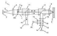
図1は、ホログラフィー記憶システムで使用されるホログラフィーピックアップを模式的に示す図で、ホログラフィー記憶システムで使用するためのホログラフィーピックアップ1の例示的な構成が示されている。コヒーレント光源、例えば、レーザーダイオード2が光ビーム3を放出し、この光ビーム3は、コリメーティングレンズ4によってコリメートされる(collimated)。典型的には、光ビーム3は、青又は緑の波長域にある。次いで光ビーム3は、2つの他の光ビーム6,7に分割される。実施例では、光ビーム3の分割が、ビーム分割器BSを使用して達成される。しかし、この目的のために他の光学的構成要素を使用することも同様に可能である。空間光変調器(SLM)5が、2次元データ模様を印すために、2つの光ビームの一方、すなわち、いわゆる「物体ビーム」6を変調する。物体ビーム6及び他方の光ビーム、すなわち、いわゆる「参照ビーム」7は共に、対物レンズ8によって、ホログラフィー記録媒体9、例えば、ホログラフィーディスクの中へ合焦される。物体ビーム6と参照ビーム7との交差部分に干渉縞が出現し、これがホログラフィー記録媒体9の光感応層の中に記録される。
FIG. 1 schematically shows a holographic pickup used in a holographic storage system, showing an exemplary configuration of a holographic pickup 1 for use in a holographic storage system. A coherent light source, for example a laser diode 2, emits a light beam 3, which is collimated by a collimating lens 4. Typically, the light beam 3 is in the blue or green wavelength range. The light beam 3 is then split into two other light beams 6,7. In an embodiment, the splitting of the light beam 3 is achieved using a beam splitter BS. However, it is equally possible to use other optical components for this purpose. A spatial light modulator (SLM) 5 modulates one of the two light beams, the so-called “object beam” 6, in order to mark a two-dimensional data pattern. Both the object beam 6 and the other light beam, ie the so-called “reference beam” 7, are focused by an
記憶されたデータは、記録されたホログラムを参照ビーム7のみで照明することによって、ホログラフィー記録媒体9から取り出される。参照ビーム7は、ホログラム構造によって回折されて、元の物体ビーム6の複写、すなわち、再現された物体ビーム10を生成する。この再現された物体ビーム10は、対物レンズ8によってコリメートされ、第1のビーム分割器11によって、2次元アレイ検出器12、例えば、CCDアレイの上に誘導される。アレイ検出器12は、記録されたデータの再現を可能にする。
The stored data is retrieved from the holographic recording medium 9 by illuminating the recorded hologram with only the reference beam 7. The reference beam 7 is diffracted by the hologram structure to produce a copy of the original object beam 6, ie a reproduced object beam 10. This reproduced object beam 10 is collimated by the
ホログラフィー記録媒体9に対する物体ビーム6及び参照ビーム7の位置決めを簡素化するために、ホログラフィー記録媒体9にはサーボ層が設けられる。ホログラフィーピックアップ1は、サーボ光ビーム14を生成するためのさらなる光源13を具備する。サーボ光ビーム14は、通常では赤の波長域にある。サーボ光ビーム14は、さらなるコリメーティングレンズ15によってコリメートされ、第2のビーム分割器17によって物体ビーム6及び参照ビーム7のビーム経路の中へ結合される。次いで、サーボ光ビーム14は、対物レンズ8によってサーボ層の上に合焦される。サーボ層によって反射された光ビームは、対物レンズ8によって再びコリメートされ、第2のビーム分割器17及び第3のビーム分割器18によって検出器20に向かって誘導される。レンズ19が、反射された光ビームを検出器20の上に合焦する。サーボ光ビーム14は、有利なことに、物体ビーム6及び参照ビーム7とは異なる波長を有する。この場合では、波長選択ビーム分割器が、第2のビーム分割器17として使用可能である。サーボ光ビーム14は、さらに、線形偏光された光ビームであることが好ましく、これは、第3のビーム分割器18を偏光選択ビーム分割器として実施することを可能にする。次に、サーボ光ビーム14の経路は、反射されたサーボ光ビーム14の偏光方向を、光源13によって放出されたサーボ光ビーム14の偏光方向に対して90度回転させるために、1/4波長板16を含んでいる。
In order to simplify the positioning of the object beam 6 and the reference beam 7 with respect to the holographic recording medium 9, the holographic recording medium 9 is provided with a servo layer. The holographic pickup 1 comprises a further
上述したように、サーボ光ビーム14は、ホログラフィー記録用に使用された光ビーム6,7と同じ対物レンズ8で、ホログラフィー記録媒体9の上に合焦される。ホログラフィー光ビーム6,7及びサーボ光ビーム14は相互に相対的に固定され、サーボ光ビーム14は、ホログラフィー記録用に使用された光ビーム6,7に対する参照としての役割を果たす。ホログラフィー光ビーム6,7及びサーボ光ビーム14は、それらの異なる波長とそれらの異なるコリメーション(collimation)とにより、異なる焦点を有する。
As described above, the
図2は、従来のホログラフィー記録媒体を示す断面図で、ホログラフィー記録媒体9の断面図が示されている。このホログラフィー記録媒体9は、ホログラム層96及びサーボ層92を有する。サーボ光ビーム14は、サーボ層92の案内構造の上に合焦されており、この構造が、サーボ層92と平坦化層93との間の鋸歯様の境界によって図示されている。この図2では、案内構造のサイズが図示目的のために誇張されている。対照的に、ホログラフィー光ビーム6,7は、ホログラム層96及びスペーサ層95を透過して、サーボ光ビーム14の波長に関して透明であるが、ホログラフィー光ビーム6,7の波長に関して反射性である二色性ミラー層(dichroic mirror layer)94の上に、選択されたホログラフィー記録過程に適切であるように合焦される。サーボ層92は、基板91の上に配置され、平坦化層93によってミラー層94から分離される。被覆層97がホログラム層96の上に配置される。適合された平坦化層93によって分離されたサーボ層92をホログラム層96の上に配置することも同様に可能である。しかし、この場合では、サーボ層92によって引き起こされるホログラフィー光ビーム6,7の歪みは、ホログラフィービーム6,7が、サーボ層92を通過するときに比較的に大きな直径を有するように、例えば、ホログラム層96とサーボ層92との間の距離を増大させることによって補償されなければならない。
FIG. 2 is a cross-sectional view showing a conventional holographic recording medium, and shows a cross-sectional view of the holographic recording medium 9. The holographic recording medium 9 has a
図3は、本発明に係るホログラフィー記録媒体を示す断面図で、ホログラフィー記録媒体9の断面図を示している。サーボ層92及び平坦化層93は、専用の色素記録層98によって置き換えられている。他の方法では、色素記録層98が位相変化材料から作製される。色素記録層98は、本質的に平坦な(フォーマットされていない)基板91の上に配置され、よって同様に本質的に平坦である。したがって、色素記録層98には穴又は凹みがない。色素記録層98は、例えば、位相変化材料又は色素材料で実現される。サーボ情報99が色素記録層98の中へ記録される。色素記録層98は、特に、ホログラフィー光ビーム6,7の反射率又は位相の変調が、サーボ情報99によって引き起こされないような様態で有利に設計される。これは、例えば、位相変化時にサーボ光ビームの波長ではその反射率を変化させるのに対して、ホログラフィー光ビームの波長では反射率が変化しない材料を使用することによって達成される。この場合では、図3に示されたように、二色性ミラー層94も割愛可能である。
FIG. 3 is a sectional view showing a holographic recording medium according to the present invention, and shows a sectional view of the holographic recording medium 9. The
専用の色素記録層98がミラー様表面の上に施されるので、予めフォーマットされた基板からの波面歪みが発生しない。したがって、色素記録層98は、平坦化層93の必要性を排除する。その結果として、任意のトラック又はサーボ構造、例えば、トラックを有するDVD様サーボ構造が、色素記録層98の中へ記録されうる。有利なことに、サーボ情報99は、媒体の製造後に施される。光ディスクの場合では、サーボ情報99が、螺旋データトラック又は同心データトラックを含んでいる。これらのトラックは、高精度記録器システムがディスク原盤作製のために同様に使用されるように、この記録器システムで記録されることが好ましい。
Since a dedicated
1 ホログラフィーピックアップ
2 レーザーダイオード
3 光ビーム
4 コリメーティングレンズ
5 空間光変調器(SLM)
6,7 ホログラフィー光ビーム
8 対物レンズ
9 ホログラフィー記録媒体
10 物体ビーム
11 第1のビーム分割器
12 2次元アレイ検出器
13 光源
14 サーボ光ビーム
15 コリメーティングレンズ
16 1/4波長板
17 第2のビーム分割器
18 第3のビーム分割器
19レンズ
20 検出器
91 基板
92 サーボ層
93 平坦化層
94 二色性ミラー層
95 スペーサ層
96 ホログラム層
97 被覆層
98 色素記録層
99 サーボ情報
1 Holographic pickup 2 Laser diode 3 Light beam 4 Collimating lens 5 Spatial light modulator (SLM)
6,7
Claims (2)
平坦な基板と、
前記平坦な基板上に配置され、ホログラフィー記録媒体に対して前記ホログラムの読み出し又は記録のための光ビームを位置決めするためのサーボ層と
を備え、該サーボ層が平坦な色素記録層であり、かつどのような浮き出し模様の案内構造も有していない、ホログラフィー記録媒体であって、
前記平坦な色素記録層は、サーボ光ビームに使用される波長とホログラフィー光ビームに使用される波長とに関して二色性の特性を有し、前記平坦な色素記録層の中に記録されたサーボ情報は、前記ホログラフィー光ビームの反射率又は位相の変調を引き起こさない、ホログラフィー記録媒体。 A hologram layer for storing a plurality of holograms;
A flat substrate;
A servo layer disposed on the flat substrate for positioning a light beam for reading or recording the hologram with respect to a holographic recording medium, the servo layer being a flat dye recording layer, and A holographic recording medium that does not have any raised guide structure,
The flat dye recording layer has dichroic characteristics with respect to the wavelength used for the servo light beam and the wavelength used for the holographic light beam, and servo information recorded in the flat dye recording layer Is a holographic recording medium that does not cause modulation of the reflectivity or phase of the holographic light beam.
Applications Claiming Priority (2)
| Application Number | Priority Date | Filing Date | Title |
|---|---|---|---|
| EP07123971.9 | 2007-12-21 | ||
| EP07123971A EP2073202A1 (en) | 2007-12-21 | 2007-12-21 | Holographic recording medium and pickup for this medium |
Publications (3)
| Publication Number | Publication Date |
|---|---|
| JP2009176404A JP2009176404A (en) | 2009-08-06 |
| JP2009176404A5 JP2009176404A5 (en) | 2011-12-15 |
| JP5575391B2 true JP5575391B2 (en) | 2014-08-20 |
Family
ID=39387318
Family Applications (1)
| Application Number | Title | Priority Date | Filing Date |
|---|---|---|---|
| JP2008321166A Expired - Fee Related JP5575391B2 (en) | 2007-12-21 | 2008-12-17 | Holographic recording medium and pickup for the recording medium |
Country Status (6)
| Country | Link |
|---|---|
| US (1) | US8077579B2 (en) |
| EP (2) | EP2073202A1 (en) |
| JP (1) | JP5575391B2 (en) |
| KR (1) | KR20090068145A (en) |
| CN (1) | CN101465140B (en) |
| DE (1) | DE602008003182D1 (en) |
Families Citing this family (2)
| Publication number | Priority date | Publication date | Assignee | Title |
|---|---|---|---|---|
| CN104700851B (en) * | 2014-12-26 | 2018-03-09 | 青岛泰谷光电工程技术有限公司 | A kind of full figure storage disc construction |
| CN115547366A (en) * | 2021-06-11 | 2022-12-30 | 华为技术有限公司 | Data writing method for multi-layer recording medium and its read-write device |
Family Cites Families (11)
| Publication number | Priority date | Publication date | Assignee | Title |
|---|---|---|---|---|
| US6574174B1 (en) * | 2000-04-15 | 2003-06-03 | Siros Technologies, Inc. | Optical data storage system with multiple layer media |
| JP2003151143A (en) | 2001-11-13 | 2003-05-23 | Minebea Co Ltd | Optical information recorder |
| JP4162511B2 (en) * | 2003-03-03 | 2008-10-08 | Tdk株式会社 | Hologram recording / reproducing method and hologram recording medium |
| JP4050656B2 (en) * | 2003-05-09 | 2008-02-20 | 株式会社東芝 | Hologram recording medium and hologram recording / reproducing method |
| JP4445963B2 (en) * | 2004-03-29 | 2010-04-07 | パイオニア株式会社 | Hologram record carrier and recording / reproducing method and apparatus |
| WO2005098829A1 (en) * | 2004-03-30 | 2005-10-20 | Pioneer Corporation | Hologram record carrier, hologram apparatus and recording method |
| JP2006155797A (en) * | 2004-11-30 | 2006-06-15 | Fujitsu Ltd | Hologram recording medium |
| JP4456527B2 (en) * | 2005-05-20 | 2010-04-28 | 株式会社日立製作所 | Optical information recording medium, and information recording method and information reproducing method using the same |
| JP2008116896A (en) * | 2006-04-18 | 2008-05-22 | Victor Co Of Japan Ltd | Holographic recording medium, recording method thereof, reproducing method thereof, recording apparatus and reproducing apparatus |
| JP4203091B2 (en) * | 2006-09-28 | 2008-12-24 | 株式会社東芝 | Optical recording medium and optical recording / reproducing apparatus using holography |
| WO2008099705A1 (en) * | 2007-02-16 | 2008-08-21 | Sanyo Electric Co., Ltd. | Recording medium and recording/reproducing device |
-
2007
- 2007-12-21 EP EP07123971A patent/EP2073202A1/en not_active Withdrawn
-
2008
- 2008-12-03 US US12/315,462 patent/US8077579B2/en not_active Expired - Fee Related
- 2008-12-09 DE DE602008003182T patent/DE602008003182D1/en active Active
- 2008-12-09 EP EP08305902A patent/EP2073203B1/en not_active Expired - Fee Related
- 2008-12-17 JP JP2008321166A patent/JP5575391B2/en not_active Expired - Fee Related
- 2008-12-18 KR KR1020080129247A patent/KR20090068145A/en not_active Application Discontinuation
- 2008-12-19 CN CN2008101841884A patent/CN101465140B/en not_active Expired - Fee Related
Also Published As
| Publication number | Publication date |
|---|---|
| KR20090068145A (en) | 2009-06-25 |
| US20090161518A1 (en) | 2009-06-25 |
| US8077579B2 (en) | 2011-12-13 |
| EP2073203B1 (en) | 2010-10-27 |
| EP2073203A1 (en) | 2009-06-24 |
| JP2009176404A (en) | 2009-08-06 |
| CN101465140B (en) | 2013-03-13 |
| CN101465140A (en) | 2009-06-24 |
| EP2073202A1 (en) | 2009-06-24 |
| DE602008003182D1 (en) | 2010-12-09 |
Similar Documents
| Publication | Publication Date | Title |
|---|---|---|
| JP5037391B2 (en) | Optical pickup, optical information recording / reproducing apparatus, and optical information recording / reproducing method | |
| JP2005293630A (en) | Hologram recording device, hologram reproducing device, hologram recording method, hologram reproducing method, and hologram recording medium | |
| JP4506679B2 (en) | Holographic disc media with servo marks | |
| US20080137494A1 (en) | Holographic Recording Medium and Pickup For This Medium | |
| JP5096191B2 (en) | Optical pickup, optical information reproducing apparatus and optical information recording / reproducing apparatus using the same | |
| JP2005322382A (en) | Hologram recording device and hologram recording method | |
| JP4881914B2 (en) | Optical information recording / reproducing apparatus and optical information recording method | |
| JP2009252287A (en) | Volume type information recording medium, information recorder, information reproducer and optical pickup | |
| JP5125351B2 (en) | Optical information recording / reproducing apparatus | |
| JP2005148700A (en) | Holographic recording apparatus, holographic reconstructing apparatus, and mask | |
| JP2007234111A (en) | Optical information recording apparatus and optical information recording medium | |
| JP5575391B2 (en) | Holographic recording medium and pickup for the recording medium | |
| US8391119B2 (en) | Apparatus and method for recording/reproducing optical information, and data fetching by reference to optical information recording medium | |
| JP4631473B2 (en) | Hologram recording / reproducing apparatus and hologram recording / reproducing method | |
| JP2007537479A (en) | Holographic master production and replication | |
| JP2006259519A (en) | Hologram recording apparatus | |
| JP4258624B2 (en) | Optical information recording device | |
| JP4548762B2 (en) | Optical information recording medium | |
| JP4882802B2 (en) | Hologram recording apparatus and hologram reproducing apparatus | |
| JP5211816B2 (en) | Optical information recording / reproducing apparatus | |
| JP4461894B2 (en) | Hologram information recording medium | |
| JP2006171416A (en) | Medium for recording hologram and apparatus for recording and reproducing hologram | |
| JP2009277272A (en) | Hologram recording and reproducing device | |
| JP4882803B2 (en) | Hologram recording apparatus and hologram reproducing apparatus | |
| JP4617487B2 (en) | Hologram recording device |
Legal Events
| Date | Code | Title | Description |
|---|---|---|---|
| A521 | Written amendment |
Free format text: JAPANESE INTERMEDIATE CODE: A523 Effective date: 20111031 |
|
| A621 | Written request for application examination |
Free format text: JAPANESE INTERMEDIATE CODE: A621 Effective date: 20111031 |
|
| A977 | Report on retrieval |
Free format text: JAPANESE INTERMEDIATE CODE: A971007 Effective date: 20121015 |
|
| A131 | Notification of reasons for refusal |
Free format text: JAPANESE INTERMEDIATE CODE: A131 Effective date: 20121019 |
|
| A521 | Written amendment |
Free format text: JAPANESE INTERMEDIATE CODE: A523 Effective date: 20130121 |
|
| A131 | Notification of reasons for refusal |
Free format text: JAPANESE INTERMEDIATE CODE: A131 Effective date: 20130802 |
|
| A521 | Written amendment |
Free format text: JAPANESE INTERMEDIATE CODE: A523 Effective date: 20131101 |
|
| TRDD | Decision of grant or rejection written | ||
| A01 | Written decision to grant a patent or to grant a registration (utility model) |
Free format text: JAPANESE INTERMEDIATE CODE: A01 Effective date: 20140603 |
|
| A61 | First payment of annual fees (during grant procedure) |
Free format text: JAPANESE INTERMEDIATE CODE: A61 Effective date: 20140702 |
|
| R150 | Certificate of patent or registration of utility model |
Ref document number: 5575391 Country of ref document: JP Free format text: JAPANESE INTERMEDIATE CODE: R150 |
|
| LAPS | Cancellation because of no payment of annual fees |