JP5211816B2 - Optical information recording / reproducing apparatus - Google Patents
Optical information recording / reproducing apparatus Download PDFInfo
- Publication number
- JP5211816B2 JP5211816B2 JP2008103026A JP2008103026A JP5211816B2 JP 5211816 B2 JP5211816 B2 JP 5211816B2 JP 2008103026 A JP2008103026 A JP 2008103026A JP 2008103026 A JP2008103026 A JP 2008103026A JP 5211816 B2 JP5211816 B2 JP 5211816B2
- Authority
- JP
- Japan
- Prior art keywords
- information recording
- optical information
- recording medium
- light
- optical
- Prior art date
- Legal status (The legal status is an assumption and is not a legal conclusion. Google has not performed a legal analysis and makes no representation as to the accuracy of the status listed.)
- Expired - Fee Related
Links
- 230000003287 optical effect Effects 0.000 title claims description 226
- 230000007547 defect Effects 0.000 claims description 64
- 238000000034 method Methods 0.000 claims description 36
- 238000001093 holography Methods 0.000 claims description 15
- 230000001678 irradiating effect Effects 0.000 claims description 5
- 230000002950 deficient Effects 0.000 claims description 4
- 238000011417 postcuring Methods 0.000 claims 1
- 230000008569 process Effects 0.000 description 18
- 238000012545 processing Methods 0.000 description 11
- 230000010287 polarization Effects 0.000 description 10
- 238000001514 detection method Methods 0.000 description 6
- 239000012535 impurity Substances 0.000 description 6
- 238000006243 chemical reaction Methods 0.000 description 4
- 239000000428 dust Substances 0.000 description 4
- 230000007274 generation of a signal involved in cell-cell signaling Effects 0.000 description 4
- 230000008901 benefit Effects 0.000 description 3
- 230000006870 function Effects 0.000 description 3
- 230000007246 mechanism Effects 0.000 description 3
- 238000002360 preparation method Methods 0.000 description 2
- 235000005811 Viola adunca Nutrition 0.000 description 1
- 240000009038 Viola odorata Species 0.000 description 1
- 235000013487 Viola odorata Nutrition 0.000 description 1
- 235000002254 Viola papilionacea Nutrition 0.000 description 1
- 230000004075 alteration Effects 0.000 description 1
- 238000000149 argon plasma sintering Methods 0.000 description 1
- 230000008859 change Effects 0.000 description 1
- 238000013036 cure process Methods 0.000 description 1
- 238000009792 diffusion process Methods 0.000 description 1
- 238000006073 displacement reaction Methods 0.000 description 1
- 230000003760 hair shine Effects 0.000 description 1
- 238000011160 research Methods 0.000 description 1
- 239000004065 semiconductor Substances 0.000 description 1
- 238000012795 verification Methods 0.000 description 1
Images


Classifications
-
- G—PHYSICS
- G11—INFORMATION STORAGE
- G11B—INFORMATION STORAGE BASED ON RELATIVE MOVEMENT BETWEEN RECORD CARRIER AND TRANSDUCER
- G11B7/00—Recording or reproducing by optical means, e.g. recording using a thermal beam of optical radiation by modifying optical properties or the physical structure, reproducing using an optical beam at lower power by sensing optical properties; Record carriers therefor
- G11B7/004—Recording, reproducing or erasing methods; Read, write or erase circuits therefor
- G11B7/0065—Recording, reproducing or erasing by using optical interference patterns, e.g. holograms
-
- G—PHYSICS
- G11—INFORMATION STORAGE
- G11B—INFORMATION STORAGE BASED ON RELATIVE MOVEMENT BETWEEN RECORD CARRIER AND TRANSDUCER
- G11B7/00—Recording or reproducing by optical means, e.g. recording using a thermal beam of optical radiation by modifying optical properties or the physical structure, reproducing using an optical beam at lower power by sensing optical properties; Record carriers therefor
- G11B7/004—Recording, reproducing or erasing methods; Read, write or erase circuits therefor
- G11B7/0045—Recording
- G11B7/00458—Verification, i.e. checking data during or after recording
Landscapes
- Optical Recording Or Reproduction (AREA)
- Signal Processing For Digital Recording And Reproducing (AREA)
- Optical Head (AREA)
- Optical Record Carriers And Manufacture Thereof (AREA)
Description
本発明は、ホログラフィを用いて、光情報記録媒体に情報を記録する、および/または光情報記録媒体から情報を再生する、装置に関する。 The present invention relates to an apparatus for recording information on and / or reproducing information from an optical information recording medium using holography.
現在、青紫色半導体レーザを用いた、Blu−ray Disc(BD)規格やHigh Definition Digital Versatile Disc(HD DVD)規格などにより、民生用においても50GB程度の記録密度を持つ光ディスクの商品化が可能となってきた。 Currently, it is possible to commercialize optical discs with a recording density of about 50 GB even for consumer use by the Blu-ray Disc (BD) standard and the High Definition Digital Versatile Disc (HD DVD) standard using a blue-violet semiconductor laser. It has become.
今後は、光ディスクでも100GB〜1TBというHDD(Hard Disc Drive)容量と同程度まで大容量化が望まれる。 In the future, it is desired to increase the capacity of an optical disk to the same level as an HDD (Hard Disc Drive) capacity of 100 GB to 1 TB.
しかしながら、このような超高密度を光ディスクで実現するためには、今までの様な短波長化と対物レンズ高NA化による従来の高密度技術のトレンドとは異なった新しいストレージ技術が必要となる。 However, in order to realize such an ultra-high density with an optical disk, a new storage technology different from the trend of the conventional high-density technology due to the shorter wavelength and the higher objective lens NA is required. .
次世代のストレージ技術に関する研究が行われる中、ホログラフィを利用してデジタル情報を記録するホログラム記録技術が注目を集めている。 While research on next-generation storage technology is underway, hologram recording technology that records digital information using holography is attracting attention.
ホログラム記録技術とは、空間光変調器により2次元的に変調されたページデータの情報を有する信号光と、参照光とを記録媒体の内部で重ね合わせ、その時に生じる干渉縞パターンによって記録媒体内に屈折率変調を生じさせることで情報を記録する技術である。 The hologram recording technique is a method in which a signal light having page data information two-dimensionally modulated by a spatial light modulator and a reference light are superimposed inside the recording medium, and an interference fringe pattern generated at that time causes the inside of the recording medium. This is a technique for recording information by causing refractive index modulation in the optical disk.
また情報の再生時には、記録時に用いた参照光を同じ配置で記録媒体に照射すると、記録媒体中に記録されているホログラムが回折格子のように作用して回折光を生じる。この回折光が記録した信号光と位相情報を含めて同一の光として再生される。 When reproducing the information, if the recording medium is irradiated with the reference light used for recording in the same arrangement, the hologram recorded in the recording medium acts like a diffraction grating to generate diffracted light. This diffracted light is reproduced as the same light including the recorded signal light and phase information.
再生された信号光は、CMOSやCCDなどの光検出器を用いて2次元的に高速に検出される。このようにホログラム記録では、1つのホログラムで2次元的な情報を同時に記録/再生され、また同じ場所に複数のページデータを重ね書きすることができるため、大容量かつ高速な情報の記録再生に有効である。 The reproduced signal light is detected two-dimensionally at high speed using a photodetector such as a CMOS or CCD. Thus, in hologram recording, two-dimensional information can be simultaneously recorded / reproduced by one hologram, and a plurality of page data can be overwritten at the same location, so that large-capacity and high-speed information can be recorded / reproduced. It is valid.
ホログラム記録技術として、例えば特許文献1がある。本公報には、信号光束をレンズで光情報記録媒体に集光すると同時に、平行光束の参照光を照射して干渉させてホログラムの記録を行い、さらに参照光の光記録媒体への入射角度を変えながら異なるページデータを空間光変調器に表示して多重記録を行う、いわゆる角度多重記録方式が記載されている。さらに本公報には、信号光をレンズで集光してそのビームウエストに開口(空間フィルタ)を配することにより、隣接するホログラムの間隔を短くすることができ、従来の角度多重記録方式に比べて記録密度/容量を増大させる技術が記載されている。
As a hologram recording technique, there is, for example,
また、ホログラム記録技術として、例えば特許文献2がある。本公報には、1つの空間光変調器において内側の画素からの光を信号光、外側の輪帯状の画素からの光を参照光として、両光束を同じレンズで光記録媒体に集光し、レンズの焦点面付近で信号光と参照光を干渉させてホログラムを記録するシフト多重方式を用いた例が記述されている。 As a hologram recording technique, for example, there is Patent Document 2. In this publication, in one spatial light modulator, light from an inner pixel is signal light, light from an outer ring-shaped pixel is reference light, and both light beams are condensed on an optical recording medium with the same lens. An example is described in which a shift multiplexing method is used in which a hologram is recorded by causing signal light and reference light to interfere with each other in the vicinity of the focal plane of the lens.
ところで、BDに代表される従来の光情報記録装置においては、光情報記録媒体に光情報記録媒体についたゴミや傷、もしくは光情報記録媒体の内部にある、気泡や不純物等の欠陥があった場合に対処する為に、記録直後にベリファイ処理を行い記録の信頼性を高めている。 By the way, in the conventional optical information recording apparatus represented by BD, the optical information recording medium has dust or scratches on the optical information recording medium, or defects such as bubbles or impurities inside the optical information recording medium. In order to deal with the case, a verify process is performed immediately after recording to improve the reliability of recording.
この時、読み出し処理に使用する光は、光情報記録媒体が変質しない強度の光を使用している。 At this time, the light used for the reading process is light having an intensity that does not alter the optical information recording medium.
しかしながら、ホログラフィを利用した光情報記録媒体の場合、光の強度によらず変質を起こしてしまう。そのため、光情報記録媒体についたゴミや傷、もしくは光情報記録媒体の内部にある、気泡や不純物等の欠陥の有る位置で記録や再生を行おうとすると、傷や欠陥、光情報記録媒体や光情報記録再生装置による光の拡散、反射により記録再生位置近辺の記録媒体が変質してしまい記録可能量の低下といった影響を与えてしまう。そのため、欠陥部分での記録や再生は情報記録媒体の信頼性を低下させる。 However, in the case of an optical information recording medium using holography, alteration occurs regardless of the light intensity. Therefore, if recording or reproduction is performed at a position where there is a defect such as a bubble or an impurity inside the optical information recording medium, or when there is a defect such as a bubble or an impurity inside the optical information recording medium, the optical information recording medium or optical The recording medium in the vicinity of the recording / reproducing position is altered by the diffusion and reflection of light by the information recording / reproducing apparatus, and the recording capacity is reduced. For this reason, recording or reproduction at a defective portion reduces the reliability of the information recording medium.
本発明は、上記問題を鑑みなされたものであり、光情報記録媒体に付いた光情報記録媒体についたゴミや傷、もしくは光情報記録媒体の内部にある、気泡や不純物等の欠陥のある光情報記録媒体であっても、欠陥を早期に発見することにより欠陥周辺の光情報記録媒体に影響を与えない記録や再生方式を提供することを目的とする。 The present invention has been made in view of the above problems, and is a light with defects such as dust and scratches on the optical information recording medium attached to the optical information recording medium, or bubbles and impurities inside the optical information recording medium. An object of the present invention is to provide a recording and reproducing method that does not affect the optical information recording medium around the defect by detecting the defect at an early stage even for the information recording medium.
本発明の目的は、以下で解決できる。 The object of the present invention can be solved as follows.
例えば一例として、参照光と信号光を光情報記録媒体に照射し、ホログラフィを利用してデジタル情報を記録および再生する光情報記録再生装置であって、参照光と信号光を光情報記録媒体に照射するピックアップと、前記光ピックアップから照射された前記参照光の位相共役光を生成する位相共役光学系と、前記光情報記録媒体のプリキュア及びポストキュアに用いる光ビームを生成するキュア光学系と、前記光情報記録媒体の欠陥の識別に用いる光ビームを生成する欠陥識別光学系と、前記欠陥識別光学系から出射され光情報記録媒体を透過もしくは反射した光を受ける光検出器とを備え、前記光情報記録媒体に記録されるデータを受け取った後、及び、受け取ったデータを前記光情報記録媒体に記録する前に、前記欠陥識別光学系から出射した光に基づいて、欠陥があるかどうかを決定する事を特徴とする光情報記録再生装置等を用いる。 For example, as an example, an optical information recording / reproducing apparatus that irradiates an optical information recording medium with reference light and signal light and records and reproduces digital information using holography, and the reference light and signal light are applied to the optical information recording medium. A pickup that irradiates; a phase conjugate optical system that generates phase conjugate light of the reference light emitted from the optical pickup; a cure optical system that generates a light beam used for pre-cure and post-cure of the optical information recording medium; A defect identifying optical system that generates a light beam used for identifying a defect in the optical information recording medium, and a photodetector that receives light emitted from the defect identifying optical system and transmitted or reflected by the optical information recording medium, After receiving the data to be recorded on the optical information recording medium and before recording the received data on the optical information recording medium, from the defect identification optical system Shines was based on the light, using an optical information recording and reproducing apparatus or the like, characterized in that to determine whether there is a defect.
本発明によれば、ホログラフィを利用したデジタル情報の記録時に光情報記録媒体についたゴミや傷、もしくは光情報記録媒体の内部にある、気泡や不純物等の欠陥のある光情報記録媒体であっても、欠陥周辺に影響を与える事無く信頼性の高い記録を行う事ができる。 According to the present invention, there is provided an optical information recording medium having defects such as dust and scratches attached to the optical information recording medium at the time of recording digital information using holography, or bubbles and impurities inside the optical information recording medium. However, highly reliable recording can be performed without affecting the periphery of the defect.
以下、本発明の実施例について説明する。 Examples of the present invention will be described below.
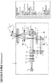
図1はホログラフィを利用してデジタル情報を記録および/または再生する光情報記録再生装置の全体的な構成を示したものである。 FIG. 1 shows the overall configuration of an optical information recording / reproducing apparatus that records and / or reproduces digital information using holography.
光情報記録再生装置10は、ピックアップ11、位相共役光学系12、ディスクキュア光学系13、ディスク回転角度検出用光学系14、欠陥識別光学系15ならびに回転モータ50を備えており、光情報記録媒体1は回転モータ50によって回転可能な構成となっている。
The optical information recording / reproducing
ピックアップ11は、参照光と信号光を光情報記録媒体1に出射してホログラフィを利用してデジタル情報を記録する役割を果たす。
The
この際、記録する情報信号はコントローラ89によって信号生成回路86を介してピックアップ11内の後述する空間光変調器に送り込まれ、信号光は該空間光変調器によって変調される。
At this time, an information signal to be recorded is sent by a controller 89 to a spatial light modulator (to be described later) in the
光情報記録媒体1に記録した情報を再生する場合は、ピックアップ11から出射された参照光の位相共役光を位相共役光学系12によって生成する。ここで位相共役光とは、入力光と同一の波面を保ちながら逆方向に進む光波のことである。該位相共役光によって再生される再生光をピックアップ11内の後述する光検出器によって検出し、信号処理回路85によって信号を再生する。
When reproducing the information recorded on the optical
光情報記録媒体1に照射する参照光と信号光の照射時間は、ピックアップ11内の後述するシャッタの開閉時間をコントローラ89によってシャッタ制御回路87を介して制御することで調整できる。
The irradiation time of the reference light and the signal light applied to the optical
ディスクキュア光学系13は、光情報記録媒体1のプリキュアおよびポストキュアに用いる光ビームを生成する役割を果たす。ここでプリキュアとは、光情報記録媒体1内の所望の位置に情報を記録する際、該所望位置に参照光と信号光を照射する前に予め所定の光ビームを照射する前工程の事である。またポストキュアとは、光情報記録媒体1内の所望の位置に情報を記録した後、該所望の位置に追記不可能とするために所定の光ビームを照射する後工程の事である。
図2は、欠陥識別光学系の光学系構成の一例である。
The disc cure
FIG. 2 shows an example of the optical system configuration of the defect identification optical system.
欠陥識別光学系15は例えば図2のようになっており、光情報記録媒体1の欠陥の識別に用いる光ビームを生成する、光源401と、光ビームを任意の広がりのあるビームにするコリメートレンズ402。さらに、光情報記録媒体1を透過もしくは反射する光ビームの光量を測定可能な光検出器403を備えている。
ここで欠陥とは、光情報記録媒体1についたゴミや傷、もしくは光情報記録媒体1の内部にある、気泡や不純物等当該部周辺のホログラフィ記録を不可能とする異物の事である。
図3は欠陥の有無による欠陥識別光学系で識別する光情報記録媒体1の透過もしくは反射光の光量の一例である。
The defect identification optical system 15 is, for example, as shown in FIG. 2, and generates a light beam used for identifying a defect in the optical
Here, the term “defect” refers to dust or scratches on the optical
FIG. 3 shows an example of the amount of transmitted or reflected light of the optical
光情報記録媒体に欠陥が有った場合、入射した光ビームが欠陥に反射及び吸収され、光検出器403で検出される光量が図3に示すように、本来光情報記録媒体1を透過する光量と比較して小さくなる。
ここで欠陥の識別とは、前記原理を利用し、光記録媒体1内の所望の位置に記録に障害となる欠陥が無いかを光情報記録媒体1に入射もしくは反射させた光の光量に閾値を持たせ、検出した光量が閾値を越えたかどうかにより欠陥の有無の識別を行う工程の事である。
When the optical information recording medium has a defect, the incident light beam is reflected and absorbed by the defect, and the amount of light detected by the
Here, the defect identification is based on the principle described above, and whether or not there is a defect that hinders recording at a desired position in the
図1のディスク回転角度検出用光学系14は、光情報記録媒体1の回転角度を検出するために用いられる。光情報記録媒体1を所定の回転角度に調整する場合は、ディスク回転角度検出用光学系14によって回転角度に応じた信号を検出し、検出された信号を用いてコントローラ89によってディスク回転モータ制御回路88を介して光情報記録媒体1の回転角度を制御する事が出来る。
The disc rotation angle detection
光源駆動回路82からは所定の光源駆動電流がピックアップ11、ディスクキュア光学系13、ディスク回転角度検出用光学系14、欠陥識別光学系15内の光源に供給され、各々の光源からは所定の光量で光ビームを発光することができる。
A predetermined light source driving current is supplied from the light source driving circuit 82 to the light sources in the
また、ピックアップ11、位相共役光学系12、ディスクキュア光学系13、欠陥識別光学系15は、光情報記録媒体1の半径方向に位置をスライドできる機構が設けられており、アクセス制御回路81を介して位置制御がおこなわれる。
The
ところでホログラフィを利用した記録技術は、超高密度な情報を記録可能な技術であるがゆえに、例えば光情報記録媒体1の傾きや位置ずれに対する許容誤差が極めて小さくなる傾向がある。それゆえピックアップ11内に、例えば光情報記録媒体1の傾きや位置ずれ等、許容誤差が小さいずれ要因のずれ量を検出する機構を設けて、サーボ信号生成回路83にてサーボ制御用の信号を生成し、サーボ制御回路84を介して該ずれ量を補正するためのサーボ機構を光情報記録再生装置10内に備えても良い。
By the way, since the recording technique using holography is a technique capable of recording ultra-high-density information, for example, an allowable error with respect to the inclination or displacement of the optical
またピックアップ11、位相共役光学系12、ディスクキュア光学系13、ディスク回転角度検出用光学系14、欠陥識別光学系15は、いくつかの光学系構成または全ての光学系構成をひとつに纏めて簡素化しても構わない。
The
図4は、光情報記録再生装置10におけるピックアップ11の光学系構成の一例を示したものである。
FIG. 4 shows an example of the optical system configuration of the
光源301を出射した光ビームはコリメートレンズ302を透過し、シャッタ303に入射する。シャッタ303が開いている時は、光ビームはシャッタ303を通過した後、例えば2分の1波長板などで構成される光学素子304によってP偏光とS偏光の光量比が所望の比になるように偏光方向を制御された後、PBS(Polarization Beam Splitter)プリズム305に入射する。
The light beam emitted from the
PBSプリズム305を透過した光ビームは、ビームエキスパンダ309によって光ビーム経を拡大された後、位相マスク311、リレーレンズ310、PBSプリズム307を経由して空間光変調器308に入射する。
The light beam transmitted through the
空間光変調器308によって情報を付加された信号光ビームはPBSプリズム307を透過し、リレーレンズ312ならびに空間フィルタ313を伝播する。その後、信号光ビームは対物レンズ325によって光情報記録媒体1に集光する。
The signal light beam to which information is added by the spatial
一方、PBSプリズム305を反射した光ビームは参照光ビームとして働き、偏光方向変換素子324によって記録時または再生時に応じて所定の偏光方向に設定された後、ミラー314ならびにミラー315を経由してガルバノミラー316に入射する。ガルバノミラー316はアクチュエータ317によって角度を調整可能のため、レンズ319とレンズ320を通過した後に情報記録媒体1に入射する参照光ビームの入射角度を、所望の角度に設定することができる。
On the other hand, the light beam reflected by the
このように信号光ビームと参照光ビームを光情報記録媒体1において、互いに重ね合うように入射させることで、記録媒体内には干渉縞パターンが形成され、このパターンを記録媒体に書き込むことで情報を記録する。またガルバノミラー316によって光情報記録媒体1に入射する参照光ビームの入射角度を変化させることができるため、角度多重による記録が可能である。
In this way, the signal light beam and the reference light beam are incident on the optical
記録した情報を再生する場合は、前述したように参照光ビームを光情報記録媒体1に入射し、光情報記録媒体1を透過した光ビームをガルバノミラー321にて反射させることで、その位相共役光を生成する。
When reproducing the recorded information, the reference light beam is incident on the optical
この位相共役光によって再生された再生光ビームは、対物レンズ325、リレーレンズ312ならびに空間フィルタ313を伝播する。その後、再生光ビームはPBSプリズム307を反射して光検出器318に入射し、記録した信号を再生することができる。
The reproduced light beam reproduced by the phase conjugate light propagates through the
なお、ピックアップ11の光学系構成は図4に限定されるものではなく、例えば図5に示すような構成であっても構わない。
図5は、光情報記録再生装置10におけるピックアップ11の光学系構成の図4とは別の一例を示したものである。
Note that the optical system configuration of the
FIG. 5 shows another example of the optical system configuration of the
図5について説明する。 FIG. 5 will be described.
光源201を出射した光ビームはコリメートレンズ202を透過し、シャッタ203に入射する。シャッタ203が開いている時は、光ビームはシャッタ203を通過した後、例えば2分の1波長板などで構成される光学素子204によってP偏光とS偏光の光量比が所望の比になるように偏光方向を制御された後、PBSプリズム205に入射する。
The light beam emitted from the
PBSプリズム205を透過した光ビームは、PBSプリズム207を経由して空間光変調器208に入射する。
The light beam that has passed through the
空間光変調器208によって情報を付加された信号光ビーム206はPBSプリズム207を反射し、所定の入射角度の光ビームのみを通過させるアングルフィルタ209を伝播する。その後、信号光ビームは対物レンズ210によって光情報記録媒体1に集光する。
The signal light beam 206 to which information is added by the spatial
一方、PBSプリズム205を反射した光ビームは参照光ビーム212として働き、偏光方向変換素子219によって記録時または再生時に応じて所定の偏光方向に設定された後、ミラー213ならびにミラー214を経由してレンズ215に入射する。
On the other hand, the light beam reflected from the
レンズ215は参照光ビーム212を対物レンズ210のバックフォーカス面に集光させる役割を果たしており、対物レンズ210のバックフォーカス面にて一度集光した参照光ビームは、対物レンズ210によって再度、平行光となって光情報記録媒体1に入射する。
The
ここで対物レンズ210または光学ブロック221は、例えば符号220に示す方向に駆動可能であり、対物レンズ210または光学ブロック221の位置を駆動方向220に沿ってずらすことにより、対物レンズ210と対物レンズ210のバックフォーカス面における集光点の相対位置関係が変化するため、光情報記録媒体1に入射する参照光ビームの入射角度を所望の角度に設定することができる。
このように信号光ビームと参照光ビームを光情報記録媒体1において、互いに重ね合うように入射させることで、記録媒体内には干渉縞パターンが形成され、このパターンを記録媒体に書き込むことで情報を記録する。また対物レンズ210または光学ブロック221の位置を駆動方向220に沿ってずらす事によって、光情報記録媒体1に入射する参照光ビームの入射角度を変化させることができるため、角度多重による記録が可能である。
Here, the
In this way, the signal light beam and the reference light beam are incident on the optical
記録した情報を再生する場合は、前述したように参照光ビームを光情報記録媒体1に入射し、光情報記録媒体1を透過した光ビームをガルバノミラー216にて反射させることで、その位相共役光を生成する。
When reproducing the recorded information, the reference light beam is incident on the optical
この位相共役光によって再生された再生光ビームは、対物レンズ210、アングルフィルタ209を伝播する。その後、再生光ビームはPBSプリズム207を透過して光検出器218に入射し、記録した信号を再生することができる。
The reproduced light beam reproduced by the phase conjugate light propagates through the
図5で示した光学系は、信号光ビームと参照光ビームを同一の対物レンズに入射させる構成とすることで、図4で示した光学系構成に比して、大幅に小型化できる利点を有する。 The optical system shown in FIG. 5 has the advantage that the signal light beam and the reference light beam are made incident on the same objective lens, so that the size can be greatly reduced as compared with the optical system configuration shown in FIG. Have.
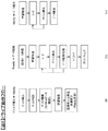
図6は、光情報記録再生装置10における記録、再生の動作フローを示したものである。ここでは、特にホログラフィを利用した記録再生に関するフローを説明する。
FIG. 6 shows an operation flow of recording and reproduction in the optical information recording / reproducing
図6(a)は、光情報記録再生装置10に光情報記録媒体1を挿入した後、記録または再生の準備が完了するまでの動作フローを示し、図6(b)は準備完了状態から光情報記録媒体1に情報を記録するまでの動作フロー、図6(c)は準備完了状態から光情報記録媒体1に記録した情報を再生するまでの動作フローを示したものである。
FIG. 6A shows an operation flow from when the optical
図6(a)に示すように媒体を挿入すると、光情報記録再生装置10は、例えば挿入された媒体がホログラフィを利用してデジタル情報を記録または再生する媒体であるかどうかディスク判別を行う。
When a medium is inserted as shown in FIG. 6A, the optical information recording / reproducing
ディスク判別の結果、ホログラフィを利用してデジタル情報を記録または再生する光情報記録媒体であると判断されると、光情報記録再生装置10は光情報記録媒体1に設けられたコントロールデータを読み出し、例えば光情報記録媒体に関する情報や、例えば記録や再生時における各種設定条件に関する情報を取得する。
As a result of disc discrimination, when it is determined that the optical information recording medium records or reproduces digital information using holography, the optical information recording / reproducing
コントロールデータの読み出し後は、コントロールデータに応じた各種調整やピックアップ11に関わる学習処理を行い、光情報記録再生装置10は、記録または再生の準備が完了する。
After reading out the control data, various adjustments according to the control data and learning processing related to the
準備完了状態から情報を記録するまでの動作フローは図6(b)に示すように、まず記録するデータを受信して、該データに応じた情報をピックアップ11内の空間光変調器に送り込む。
As shown in FIG. 6B, the operation flow from the preparation completion state to recording of information first receives data to be recorded, and sends information corresponding to the data to the spatial light modulator in the
その後、光情報記録媒体1に高品質の情報を記録できるように、必要に応じて各種学習処理を事前に行い、シーク動作ならびにアドレス再生を繰り返しながらピックアップ11ならびにディスクキュア光学系13ならびに欠陥識別光学系15の位置を光情報記録媒体の所定の位置に配置する。
その後、後述するデータ記録処理を行い光情報記録媒体1にデータを記録する。
データを記録した後は、必要に応じてデータをベリファイし、ディスクキュア光学系から出射する光ビームを用いてポストキュアを行う。
After that, various learning processes are performed in advance so that high-quality information can be recorded on the optical
Thereafter, data recording processing described later is performed to record data on the optical
After the data is recorded, the data is verified as necessary, and post cure is performed using a light beam emitted from the disk cure optical system.
準備完了状態から記録された情報を再生するまでの動作フローは図6(c)に示すように、光情報記録媒体から高品質の情報を再生できるように、必要に応じて各種学習処理を事前に行う。その後、シーク動作ならびにアドレス再生を繰り返しながらピックアップ11ならびに位相共役光学系12の位置を光情報記録媒体の所定の位置に配置する。
As shown in FIG. 6C, the operation flow from the ready state to the reproduction of recorded information is performed in advance with various learning processes as necessary so that high-quality information can be reproduced from the optical information recording medium. To do. Thereafter, the positions of the
その後、ピックアップ11から参照光を出射し、光情報記録媒体に記録された情報を読み出す。
Thereafter, reference light is emitted from the
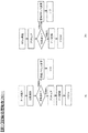
ここで、図6(b)のデータ記録処理動作について詳細に説明する。
図7(a)に、図6(b)の、データ記録処理の内部動作フローを示す。
シーク動作ならびにアドレス再生を繰り返しながらピックアップ11ならびにディスクキュア光学系13ならびに欠陥識別光学系15の位置を光情報記録媒体の所定の位置に配置した後、欠陥識別光学系15から出射する光ビームの光情報記録媒体1への透過もしくは反射光の光量より光情報記録媒体1の欠陥の有無を識別する。欠陥ありと識別した場合、目標記録アドレスを変更し再度シーク処理から行う。
欠陥なしと識別した場合は、その後、ディスクキュア光学系13から出射する光ビームを用いて所定の領域をプリキュアし、ピックアップ11から出射する参照光と信号光を用いてデータを記録する。
Here, the data recording processing operation of FIG. 6B will be described in detail.
FIG. 7A shows an internal operation flow of the data recording process of FIG.
The light of the light beam emitted from the defect identification optical system 15 after the positions of the
If it is identified that there is no defect, then a predetermined area is pre-cured using the light beam emitted from the disk cure
ここで、記録開始初期に欠陥を識別する処理を入れることにより従来の記録手法では欠陥識別までにプリキュア データ記録 ベリファイと全ての処理を行う必要のあった処理を短縮する事が出来る。この為、欠陥の存在する光情報記録媒体1に情報を記録する場合に記録速度が向上するという利点がある。また欠陥は光の散乱や反射を起こし、欠陥周辺の記録部に不要の光を当ててしまい、欠陥部周辺の記録容量を少なくしてしまうがプリキュア前に検出処理を行う事により欠陥部周辺への影響を少なくする事が出来るという利点もある。
Here, by inserting a process for identifying a defect at the beginning of recording, the conventional recording method can shorten the process that required the pre-cure data recording verification and all the processes before the defect identification. For this reason, there is an advantage that the recording speed is improved when information is recorded on the optical
ここで図7(b)は、ディスクキュア光学系13と欠陥識別光学系15の光学系をまとめてしまいプリキュア時に欠陥の識別を行うこととした場合の図6(b)の、データ記録処理の内部動作フローである。
Here, FIG. 7B shows the data recording process of FIG. 6B when the optical systems of the disc cure
シーク動作ならびにアドレス再生を繰り返しながらピックアップ11ならびにディスクキュア光学系13ならびに欠陥識別光学系15の位置を光情報記録媒体の所定の位置に配置した後、ディスクキュア光学系13から出射する光ビームを用いて所定の領域をプリキュアし同時に光情報記録媒体1への透過もしくは反射光の光量より光情報記録媒体1の欠陥の有無を識別する。欠陥ありと識別した場合、即座にプリキュア処理を止め、目標記録アドレスを変更し再度シーク処理から行う。
欠陥なしと識別した場合は、その後、ピックアップ11から出射する参照光と信号光を用いてデータを記録する。
The light beam emitted from the disk cure
If it is identified that there is no defect, then data is recorded using reference light and signal light emitted from the
ここで、図7(b)の処理はプリキュア動作と欠陥識別を同時に行うことが出来る為、図7(a)での記録動作より処理の速度を速める事が出来る。
また、欠陥識別の為の光ビームをキュア部から出射される光ビームを使用することにより欠陥識別光学系に光ビームを出射する機能を省く事が出来る為装置を簡略化する事が出来る。
Here, since the precuring operation and the defect identification can be performed simultaneously in the processing of FIG. 7B, the processing speed can be increased compared to the recording operation of FIG.
Further, by using the light beam emitted from the cure portion as the light beam for defect identification, the function of emitting the light beam to the defect identification optical system can be omitted, and the apparatus can be simplified.
また、光情報記録媒体1の記録処理にプリキュア、ポストキュアの必要が無く記録する事が可能な場合の記録処理フローを図8(a)に示す。
シーク動作ならびにアドレス再生を繰り返しながらピックアップ11ならびに欠陥識別光学系15の位置を光情報記録媒体の所定の位置に配置した後、ピックアップ11から出射する参照光と信号光を用いて1多重分のデータを記録する。この時参照光もしくは信号光の透過もしくは反射光の光量を欠陥識別光学系に備えた光検出器により受光し欠陥の有無を識別する。
FIG. 8A shows a recording process flow in the case where recording can be performed without the need for pre-cure and post-cure in the recording process of the optical
After the seek operation and the address reproduction are repeated, the position of the
ここで、欠陥ありと識別した場合、即座にプリキュア処理を止め、目標記録アドレスを変更し再度シーク処理から行う。
欠陥なしと識別した場合は、所定の位置に追加で多重記録を行うかを判断する。
多重で記録を行う場合は、ピックアップ11を次の多重記録を行える位置に配置し、ピックアップ11から出射する参照光と信号光を用いて1多重分のデータの記録を繰り返す。
これ以上の多重記録を行う必要がなくなった場合、必要があればベリファイ処理へ移動する。
Here, when it is identified that there is a defect, the precure process is immediately stopped, the target recording address is changed, and the seek process is performed again.
When it is identified that there is no defect, it is determined whether or not multiple recording is additionally performed at a predetermined position.
In the case of performing multiplex recording, the
If it is no longer necessary to perform multiple recording, the process moves to verify processing if necessary.
ここで、前述した、図7(a)、図7(b)及び図8(a)の欠陥識別により、欠陥があったとして記録を行わなかった位置情報を光情報記録媒体1に設けられたコントロールデータに記録を行うと、以降のディスク挿入時にコントロールデータ読み出し欠陥位置を識別する事が出来、当該位置での記録再生動作を制御できる。
Here, according to the defect identification shown in FIGS. 7A, 7B, and 8A described above, position information that was not recorded as having a defect was provided in the optical
ここで、一般に欠陥の位置情報はホログラムの1つの位置に記録出来る情報量に比べると小さいデータ量である。また、ホログラムの記録は1ページ毎に行う為、記録する情報の量が小さくても一定量以上の記録容量を使用してしまう事になる。 Here, in general, the position information of the defect is a small amount of data compared to the amount of information that can be recorded at one position of the hologram. Further, since hologram recording is performed for each page, a recording capacity of a certain amount or more is used even if the amount of information to be recorded is small.
その為、記録を行わなかった位置情報の記録を欠陥発見毎に行っているとコントロールデータの記録容量を無駄遣いしてしまう。 Therefore, if the recording of the position information that has not been recorded is performed every time a defect is found, the recording capacity of the control data is wasted.
そこで、記録を行わなかった位置情報は、記録が終了した後や、ディスクの取り出し操作が行われた時に行うと、ホログラム管理領域の使用量を削減する事が出来る為良い。 Therefore, if the position information that has not been recorded is recorded after the recording is completed or when the disk is ejected, the amount of use of the hologram management area can be reduced.
1・・・光情報記録媒体、10・・・光情報記録再生装置、11・・・ピックアップ、
12・・・位相共役光学系、13・・・ディスクキュア光学系、
14・・・ディスク回転角度検出用光学系、15・・・欠陥識別光学系、
50・・・回転モータ、81・・・アクセス制御回路、
82・・・光源駆動回路、83・・・サーボ信号生成回路、
84・・・サーボ制御回路、85・・・信号処理回路、86・・・信号生成回路、
87・・・シャッタ制御回路、88・・・ディスク回転モータ制御回路、
89・・・コントローラ、
201・・・光源、202・・・コリメートレンズ、203・・・シャッタ、
204・・・光学素子、205・・・偏光ビームスプリッタ、206・・・信号光、
207・・・偏光ビームスプリッタ、208・・・空間光変調器、
209・・・アングルフィルタ、210・・・対物レンズ、
211・・・対物レンズアクチュエータ、212・・・参照光、213・・・ミラー、
214・・・ミラー、215・・・レンズ、216・・・ミラー、217・・・アクチュエータ、
218・・・光検出器、219・・・偏光方向変換素子、220・・・駆動方向、
221・・・光学ブロック、
301・・・光源、302・・・コリメートレンズ、303・・・シャッタ、
304・・・光学素子、305・・・偏光ビームスプリッタ、
306・・・信号光、307・・・偏光ビームスプリッタ、308・・・空間光変調器、
309・・・ビームエキスパンダ、310・・・リレーレンズ、
311・・・フェーズ(位相)マスク、312・・・リレーレンズ、
313・・・空間フィルタ、314・・・ミラー、315・・・ミラー、
316・・・ミラー、317・・・アクチュエータ、318・・・光検出器、
319・・・レンズ、320・・・レンズ、321・・・ミラー、322・・・アクチュエータ、
323・・・参照光、324・・・偏光方向変換素子、325・・・対物レンズ、
401・・・光源、402・・・コリメートレンズ、403・・・光検出器。
DESCRIPTION OF
12 ... Phase conjugate optical system, 13 ... Disc cure optical system,
14 ... Optical system for detecting disk rotation angle, 15 ... Defect identification optical system,
50 ... Rotary motor, 81 ... Access control circuit,
82... Light source drive circuit, 83... Servo signal generation circuit,
84 ... Servo control circuit, 85 ... Signal processing circuit, 86 ... Signal generation circuit,
87 ... Shutter control circuit, 88 ... Disc rotation motor control circuit,
89 ... Controller,
201 ... light source, 202 ... collimating lens, 203 ... shutter,
204... Optical element, 205... Polarizing beam splitter, 206.
207 ... Polarizing beam splitter, 208 ... Spatial light modulator,
209 ... Angle filter, 210 ... Objective lens,
211 ... Objective lens actuator, 212 ... Reference beam, 213 ... Mirror,
214 ... mirror, 215 ... lens, 216 ... mirror, 217 ... actuator,
218 ... photodetector, 219 ... polarization direction conversion element, 220 ... drive direction,
221: Optical block,
301 ... Light source, 302 ... Collimating lens, 303 ... Shutter,
304 ... Optical element, 305 ... Polarizing beam splitter,
306... Signal light, 307... Polarization beam splitter, 308... Spatial light modulator,
309 ... Beam expander, 310 ... Relay lens,
311 ... Phase mask, 312 ... Relay lens,
313 ... Spatial filter, 314 ... Mirror, 315 ... Mirror,
316 ... mirror, 317 ... actuator, 318 ... photodetector,
319 ... lens, 320 ... lens, 321 ... mirror, 322 ... actuator,
323 ... reference light, 324 ... polarization direction conversion element, 325 ... objective lens,
401 ... light source, 402 ... collimating lens, 403 ... light detector.
Claims (6)
参照光と信号光を光情報記録媒体に照射するピックアップと、
前記光ピックアップから照射された前記参照光の位相共役光を生成する位相共役光学系と、
前記光情報記録媒体のプリキュア及びポストキュアに用いる光ビームを生成するキュア光学系と、
前記キュア光学系から出射され光情報記録媒体を透過もしくは反射した光を受ける光検出器と、
前記参照光の前記光情報記録媒体に照射する角度を変更する角度変更手段と、
を備え、
前記光情報記録媒体の同一箇所に、前記参照光の照射角度を変える事で角度多重記録を行う光情報記録再生装置であって、
前記光情報記録媒体に記録されるデータを受け取った後、及び、受け取ったデータを前記光情報記録媒体に角度多重記録する前に、前記キュア光学系から出射し、前記光情報記録媒体の角度多重記録位置に対して最初に透過もしくは反射した光に基づいて、欠陥があるかどうかを決定する事を特徴とする光情報記録再生装置。 An optical information recording / reproducing apparatus that irradiates an optical information recording medium with reference light and signal light and records and reproduces digital information using holography,
A pickup that irradiates the optical information recording medium with reference light and signal light;
A phase conjugate optical system that generates phase conjugate light of the reference light emitted from the optical pickup;
A curing optical system for generating a light beam used for pre-curing and post-curing of the optical information recording medium;
A photodetector for receiving light emitted from the cure optical system and transmitted or reflected by the optical information recording medium;
Angle changing means for changing the angle of the reference light applied to the optical information recording medium;
With
An optical information recording / reproducing apparatus that performs angle multiplex recording by changing the irradiation angle of the reference light at the same location of the optical information recording medium,
After receiving the data to be recorded on the optical information recording medium and before angle-multiplexing the received data on the optical information recording medium, the data is emitted from the cure optical system, and the angle multiplexing of the optical information recording medium is performed. An optical information recording / reproducing apparatus characterized by determining whether or not there is a defect based on light transmitted or reflected first with respect to a recording position .
参照光と信号光を光情報記録媒体に照射するピックアップと、
前記光ピックアップから照射された前記参照光の位相共役光を生成する位相共役光学系と、
前記参照光の前記光情報記録媒体に照射する角度を変更する角度変更手段と、
を備え、
前記光情報記録媒体の同一箇所に、前記参照光の照射角度を変える事で角度多重記録を行う光情報記録再生装置であって、
前記光情報記録媒体に記録されるデータを受け取った後、及び、受け取ったデータを前記光情報記録媒体に角度多重記録する前に、前記光情報記録媒体上の角度多重記録位置に対して最初に照射された参照光又は信号光のどちらかの透過光又は反射光に基づいて、前記光情報記録媒体に欠陥があるかどうかを決定し、
記録時に情報記録媒体へ出射された参照光もしくは信号光の透過光もしくは反射光の光量に基づき情報の記録を続けるか、中断するかを判断することを特徴とする光情報記録再生装置。 An optical information recording / reproducing apparatus that irradiates an optical information recording medium with reference light and signal light and records and reproduces digital information using holography,
A pickup that irradiates the optical information recording medium with reference light and signal light;
A phase conjugate optical system that generates phase conjugate light of the reference light emitted from the optical pickup;
Angle changing means for changing the angle of the reference light applied to the optical information recording medium;
With
An optical information recording / reproducing apparatus that performs angle multiplex recording by changing the irradiation angle of the reference light at the same location of the optical information recording medium,
After receiving the data to be recorded on the optical information recording medium and before angle-multiplexing the received data on the optical information recording medium, first , the angle multiplexing recording position on the optical information recording medium is first Based on the transmitted light or reflected light of either the irradiated reference light or signal light, determine whether the optical information recording medium is defective,
An optical information recording / reproducing apparatus for determining whether to continue or stop recording information based on the amount of transmitted light or reflected light of reference light or signal light emitted to an information recording medium during recording.
参照光と信号光を光情報記録媒体に照射するステップと、
前記光ピックアップから照射された前記参照光の位相共役光を生成するステップと、
前記光情報記録媒体のプリキュア及びポストキュアに用いる光ビームを生成するステップと、
前記キュア光生成ステップで生成され、光情報記録媒体を透過もしくは反射した光を検出するステップと含み、
前記光情報記録媒体に記録されるデータを受け取った後、及び、受け取ったデータを前記光情報記録媒体に角度多重で記録する前に、前記キュア光生成ステップで生成され、光情報記録媒体の角度多重記録位置に対して最初に透過もしくは反射した光に基づいて、欠陥があるかどうかを決定する事を特徴とする光情報記録再生方法。 The optical information recording medium is irradiated with reference light and signal light, digital information is recorded and reproduced using holography, and angle-multiplexed recording and recording are performed by changing the irradiation angle of the reference light at the same location of the optical information recording medium. An information recording / reproducing method for reproducing,
Irradiating the optical information recording medium with reference light and signal light;
Generating phase conjugate light of the reference light irradiated from the optical pickup;
Generating a light beam used for pre-cure and post-cure of the optical information recording medium;
Detecting the light generated in the curing light generation step and transmitted or reflected by the optical information recording medium,
After receiving the data to be recorded in said optical information recording medium, and, before recording the received data in the angular multiplexing in the optical information recording medium, generated by the curing light generating step, the angle of the optical information recording medium An optical information recording / reproducing method characterized by determining whether or not there is a defect based on light transmitted or reflected first with respect to a multiple recording position .
参照光と信号光を光情報記録媒体に照射するステップと、
前記光情報記録媒体に照射された前記参照光の位相共役光を生成するステップと、
前記光情報記録媒体に記録されるデータを受け取った後、及び、受け取ったデータを前記光情報記録媒体に角度多重で記録する前に、前記光情報記録媒体上の角度多重記録位置に対して最初に照射された参照光又は信号光のどちらかの透過光又は反射光に基づいて、前記光情報記録媒体に欠陥があるかどうかを決定するステップと、
ホログラフィ記録時に情報記録媒体へ出射された参照光もしくは信号光の透過光もしくは反射光の光量に基づき情報の記録を続けるか、中断するかを判断するステップとを含む光情報記録再生方法。 The optical information recording medium is irradiated with reference light and signal light, digital information is recorded and reproduced using holography, and angle-multiplexed recording and recording are performed by changing the irradiation angle of the reference light at the same location of the optical information recording medium. An optical information recording / reproducing method for reproducing,
Irradiating the optical information recording medium with reference light and signal light;
Generating phase conjugate light of the reference light irradiated on the optical information recording medium;
After receiving the data to be recorded on the optical information recording medium, and before recording the received data on the optical information recording medium by angle multiplexing, the first time with respect to the angle multiplexing recording position on the optical information recording medium Determining whether the optical information recording medium is defective based on the transmitted light or reflected light of either the reference light or the signal light irradiated to
An optical information recording / reproducing method including a step of determining whether or not to continue recording information based on the amount of transmitted light or reflected light of reference light or signal light emitted to an information recording medium during holographic recording.
Priority Applications (3)
| Application Number | Priority Date | Filing Date | Title |
|---|---|---|---|
| JP2008103026A JP5211816B2 (en) | 2008-04-11 | 2008-04-11 | Optical information recording / reproducing apparatus |
| CN200910118355.XA CN101556805B (en) | 2008-04-11 | 2009-02-27 | Optical information recording and reproducing apparatus |
| US12/420,205 US8077580B2 (en) | 2008-04-11 | 2009-04-08 | Optical information recording and reproducing apparatus |
Applications Claiming Priority (1)
| Application Number | Priority Date | Filing Date | Title |
|---|---|---|---|
| JP2008103026A JP5211816B2 (en) | 2008-04-11 | 2008-04-11 | Optical information recording / reproducing apparatus |
Publications (3)
| Publication Number | Publication Date |
|---|---|
| JP2009252339A JP2009252339A (en) | 2009-10-29 |
| JP2009252339A5 JP2009252339A5 (en) | 2011-03-17 |
| JP5211816B2 true JP5211816B2 (en) | 2013-06-12 |
Family
ID=41163890
Family Applications (1)
| Application Number | Title | Priority Date | Filing Date |
|---|---|---|---|
| JP2008103026A Expired - Fee Related JP5211816B2 (en) | 2008-04-11 | 2008-04-11 | Optical information recording / reproducing apparatus |
Country Status (3)
| Country | Link |
|---|---|
| US (1) | US8077580B2 (en) |
| JP (1) | JP5211816B2 (en) |
| CN (1) | CN101556805B (en) |
Families Citing this family (2)
| Publication number | Priority date | Publication date | Assignee | Title |
|---|---|---|---|---|
| JP5647965B2 (en) * | 2011-09-30 | 2015-01-07 | 日立コンシューマエレクトロニクス株式会社 | Optical information recording / reproducing apparatus, optical information recording apparatus, optical information recording / reproducing method, and optical information recording medium |
| CN104798134B (en) * | 2012-11-19 | 2017-06-09 | 日立民用电子株式会社 | Device for optical information recording, optical information recording/reproducing device, light information recording method, optical information recording/reproducing method and optical element |
Family Cites Families (28)
| Publication number | Priority date | Publication date | Assignee | Title |
|---|---|---|---|---|
| JPH0782667B2 (en) | 1984-10-26 | 1995-09-06 | 東芝イ−エムアイ株式会社 | Non-contact type defect detection method and apparatus for recording medium |
| JPH0782668B2 (en) | 1984-10-26 | 1995-09-06 | 東芝イ−エムアイ株式会社 | Non-contact type defect detection method and apparatus for recording medium |
| JPH04168638A (en) | 1990-11-01 | 1992-06-16 | Seiko Epson Corp | Defect inspection device |
| JPH04271076A (en) | 1991-02-26 | 1992-09-28 | Dainippon Ink & Chem Inc | Scratch defect checking method for optical disk |
| JPH05325187A (en) * | 1992-05-25 | 1993-12-10 | Kuraray Co Ltd | Optical disk apparatus |
| JPH07176049A (en) | 1993-12-20 | 1995-07-14 | Idemitsu Material Kk | Detection and detector of defect of disk-shaped recording medium |
| JPH07249240A (en) | 1994-03-10 | 1995-09-26 | Nippon Kagaku Kogyo Kk | Optical disk defect inspecting method and optical disc defect inspecting device |
| JPH09190628A (en) | 1996-01-10 | 1997-07-22 | Sony Corp | Method and device for inspecting optical disk defect |
| JP2003178538A (en) | 2001-12-10 | 2003-06-27 | Nippon Telegr & Teleph Corp <Ntt> | Optical recording medium recording and reproducing method and apparatus thereof |
| JP2004227632A (en) * | 2003-01-21 | 2004-08-12 | Nippon Telegr & Teleph Corp <Ntt> | Method and device for recording/reproducing optical recording medium |
| US7092133B2 (en) | 2003-03-10 | 2006-08-15 | Inphase Technologies, Inc. | Polytopic multiplex holography |
| EP1624451B1 (en) | 2003-05-13 | 2011-01-26 | Optware Corporation | Optical information recording/reproduction device and method |
| JP4544578B2 (en) * | 2004-09-10 | 2010-09-15 | 株式会社キーエンス | Defect inspection method and defect inspection apparatus using computer |
| JP2006112991A (en) * | 2004-10-18 | 2006-04-27 | Toppan Printing Co Ltd | Lighting method for imaging, hologram image acquisition method, and hologram defect extraction method |
| JP2006139834A (en) * | 2004-11-11 | 2006-06-01 | Sony Corp | Disk recording apparatus and recording control method |
| JP2006235261A (en) * | 2005-02-25 | 2006-09-07 | Alps Electric Co Ltd | Hologram information regenerative apparatus |
| JP4701751B2 (en) * | 2005-03-02 | 2011-06-15 | ソニー株式会社 | Hologram recording apparatus and hologram recording method |
| JP2006252699A (en) | 2005-03-11 | 2006-09-21 | Fujitsu Ltd | Recording and reproducing apparatus |
| JP4384614B2 (en) | 2005-03-31 | 2009-12-16 | 日本電信電話株式会社 | Laminated waveguide hologram memory, hologram reproducing apparatus and information recording method |
| US7742211B2 (en) * | 2005-05-26 | 2010-06-22 | Inphase Technologies, Inc. | Sensing and correcting angular orientation of holographic media in a holographic memory system by partial reflection, the system including a galvano mirror |
| JP2006343533A (en) * | 2005-06-09 | 2006-12-21 | Sony Corp | Hologram device and incoherent light generation method |
| KR20080083634A (en) | 2005-11-10 | 2008-09-18 | 체크플릭스, 인코포레이티드 | Apparatus and method for analysis of optical storage media |
| JP4544164B2 (en) | 2006-01-24 | 2010-09-15 | ソニー株式会社 | Recording / reproducing apparatus, defect determination method |
| JP2007248595A (en) | 2006-03-14 | 2007-09-27 | Victor Co Of Japan Ltd | Optical disk and optical information recording method |
| KR100738984B1 (en) * | 2006-06-07 | 2007-07-13 | 주식회사 대우일렉트로닉스 | Apparatus for processing optical information, method of recoding and reading optical information thereof |
| US20080059144A1 (en) * | 2006-09-01 | 2008-03-06 | Inphase Technologies | Emulation of dissimilar removable medium storage device types assisted by information embedded in the logical format |
| JP2008112482A (en) * | 2006-10-30 | 2008-05-15 | Hitachi Ltd | Optical disk recording device |
| JP4697813B2 (en) * | 2007-03-22 | 2011-06-08 | 船井電機株式会社 | Hologram recording / reproducing apparatus and hologram recording apparatus |
-
2008
- 2008-04-11 JP JP2008103026A patent/JP5211816B2/en not_active Expired - Fee Related
-
2009
- 2009-02-27 CN CN200910118355.XA patent/CN101556805B/en not_active Expired - Fee Related
- 2009-04-08 US US12/420,205 patent/US8077580B2/en not_active Expired - Fee Related
Also Published As
| Publication number | Publication date |
|---|---|
| CN101556805B (en) | 2013-01-16 |
| CN101556805A (en) | 2009-10-14 |
| US8077580B2 (en) | 2011-12-13 |
| US20090257337A1 (en) | 2009-10-15 |
| JP2009252339A (en) | 2009-10-29 |
Similar Documents
| Publication | Publication Date | Title |
|---|---|---|
| US8300511B2 (en) | Optical information record/reproduction apparatus and reproduction apparatus | |
| JP5037391B2 (en) | Optical pickup, optical information recording / reproducing apparatus, and optical information recording / reproducing method | |
| JP2009070475A (en) | Optical information recording/reproducing system | |
| JP4881914B2 (en) | Optical information recording / reproducing apparatus and optical information recording method | |
| JP5096191B2 (en) | Optical pickup, optical information reproducing apparatus and optical information recording / reproducing apparatus using the same | |
| JP5125351B2 (en) | Optical information recording / reproducing apparatus | |
| JP4969558B2 (en) | Optical information reproducing apparatus, optical information recording / reproducing apparatus | |
| WO2014199504A1 (en) | Optical information recording/reproduction device and adjustment method | |
| JP5320343B2 (en) | Optical information recording / reproducing apparatus and optical information recording / reproducing method | |
| JP5211816B2 (en) | Optical information recording / reproducing apparatus | |
| JP5238209B2 (en) | Optical information recording / reproducing apparatus and method, and optical information recording medium | |
| JP2013109794A (en) | Optical information recording/reproducing apparatus, optical information recording/reproducing method, and optical information recording medium | |
| JP5557787B2 (en) | Optical information reproducing apparatus, optical information recording / reproducing apparatus | |
| JP5049988B2 (en) | Signal quality evaluation apparatus, signal quality evaluation method, and information recording medium | |
| US8144557B2 (en) | Optical information recording/reproducing apparatus and disk distinction method | |
| JP2012069207A (en) | Holographic memory using holography | |
| JP5647965B2 (en) | Optical information recording / reproducing apparatus, optical information recording apparatus, optical information recording / reproducing method, and optical information recording medium | |
| JP5802494B2 (en) | Holographic memory reproducing device, holographic memory reproducing method and hologram recording medium | |
| JP2011187101A (en) | Optical information recording/reproducing device and optical information reproducing method | |
| JP5542739B2 (en) | Holographic memory reproducing apparatus and holographic memory reproducing method | |
| JP6078634B2 (en) | Optical information reproducing apparatus and optical information recording / reproducing apparatus | |
| WO2012160733A1 (en) | Optical information recording/reproduction device and optical information recording/reproduction method | |
| JP2010225245A (en) | Optical information reproducing method, optical information reproducing device, and optical information recording medium | |
| JP2016009508A (en) | Optical information reproducing device and optical information reproducing method |
Legal Events
| Date | Code | Title | Description |
|---|---|---|---|
| A521 | Request for written amendment filed |
Free format text: JAPANESE INTERMEDIATE CODE: A523 Effective date: 20110131 |
|
| A621 | Written request for application examination |
Free format text: JAPANESE INTERMEDIATE CODE: A621 Effective date: 20110131 |
|
| A977 | Report on retrieval |
Free format text: JAPANESE INTERMEDIATE CODE: A971007 Effective date: 20110920 |
|
| A131 | Notification of reasons for refusal |
Free format text: JAPANESE INTERMEDIATE CODE: A131 Effective date: 20111004 |
|
| A521 | Request for written amendment filed |
Free format text: JAPANESE INTERMEDIATE CODE: A523 Effective date: 20111130 |
|
| A131 | Notification of reasons for refusal |
Free format text: JAPANESE INTERMEDIATE CODE: A131 Effective date: 20120605 |
|
| A521 | Request for written amendment filed |
Free format text: JAPANESE INTERMEDIATE CODE: A523 Effective date: 20120724 |
|
| A02 | Decision of refusal |
Free format text: JAPANESE INTERMEDIATE CODE: A02 Effective date: 20121002 |
|
| A521 | Request for written amendment filed |
Free format text: JAPANESE INTERMEDIATE CODE: A523 Effective date: 20121219 |
|
| A911 | Transfer to examiner for re-examination before appeal (zenchi) |
Free format text: JAPANESE INTERMEDIATE CODE: A911 Effective date: 20121228 |
|
| TRDD | Decision of grant or rejection written | ||
| A01 | Written decision to grant a patent or to grant a registration (utility model) |
Free format text: JAPANESE INTERMEDIATE CODE: A01 Effective date: 20130129 |
|
| A61 | First payment of annual fees (during grant procedure) |
Free format text: JAPANESE INTERMEDIATE CODE: A61 Effective date: 20130211 |
|
| R151 | Written notification of patent or utility model registration |
Ref document number: 5211816 Country of ref document: JP Free format text: JAPANESE INTERMEDIATE CODE: R151 |
|
| FPAY | Renewal fee payment (event date is renewal date of database) |
Free format text: PAYMENT UNTIL: 20160308 Year of fee payment: 3 |
|
| S111 | Request for change of ownership or part of ownership |
Free format text: JAPANESE INTERMEDIATE CODE: R313111 |
|
| R350 | Written notification of registration of transfer |
Free format text: JAPANESE INTERMEDIATE CODE: R350 |
|
| LAPS | Cancellation because of no payment of annual fees |