JP5565082B2 - Transmission power determination method, communication apparatus, and program - Google Patents
Transmission power determination method, communication apparatus, and program Download PDFInfo
- Publication number
- JP5565082B2 JP5565082B2 JP2010110012A JP2010110012A JP5565082B2 JP 5565082 B2 JP5565082 B2 JP 5565082B2 JP 2010110012 A JP2010110012 A JP 2010110012A JP 2010110012 A JP2010110012 A JP 2010110012A JP 5565082 B2 JP5565082 B2 JP 5565082B2
- Authority
- JP
- Japan
- Prior art keywords
- communication service
- communication
- transmission power
- node
- radio signal
- Prior art date
- Legal status (The legal status is an assumption and is not a legal conclusion. Google has not performed a legal analysis and makes no representation as to the accuracy of the status listed.)
- Active
Links
Images


Classifications
-
- H—ELECTRICITY
- H04—ELECTRIC COMMUNICATION TECHNIQUE
- H04W—WIRELESS COMMUNICATION NETWORKS
- H04W24/00—Supervisory, monitoring or testing arrangements
-
- H—ELECTRICITY
- H04—ELECTRIC COMMUNICATION TECHNIQUE
- H04W—WIRELESS COMMUNICATION NETWORKS
- H04W24/00—Supervisory, monitoring or testing arrangements
- H04W24/02—Arrangements for optimising operational condition
-
- H—ELECTRICITY
- H04—ELECTRIC COMMUNICATION TECHNIQUE
- H04W—WIRELESS COMMUNICATION NETWORKS
- H04W52/00—Power management, e.g. TPC [Transmission Power Control], power saving or power classes
- H04W52/04—TPC
- H04W52/06—TPC algorithms
- H04W52/14—Separate analysis of uplink or downlink
- H04W52/146—Uplink power control
-
- H—ELECTRICITY
- H04—ELECTRIC COMMUNICATION TECHNIQUE
- H04W—WIRELESS COMMUNICATION NETWORKS
- H04W52/00—Power management, e.g. TPC [Transmission Power Control], power saving or power classes
- H04W52/04—TPC
- H04W52/06—TPC algorithms
- H04W52/16—Deriving transmission power values from another channel
-
- H—ELECTRICITY
- H04—ELECTRIC COMMUNICATION TECHNIQUE
- H04W—WIRELESS COMMUNICATION NETWORKS
- H04W52/00—Power management, e.g. TPC [Transmission Power Control], power saving or power classes
- H04W52/04—TPC
- H04W52/18—TPC being performed according to specific parameters
- H04W52/24—TPC being performed according to specific parameters using SIR [Signal to Interference Ratio] or other wireless path parameters
- H04W52/241—TPC being performed according to specific parameters using SIR [Signal to Interference Ratio] or other wireless path parameters taking into account channel quality metrics, e.g. SIR, SNR, CIR, Eb/lo
-
- H—ELECTRICITY
- H04—ELECTRIC COMMUNICATION TECHNIQUE
- H04W—WIRELESS COMMUNICATION NETWORKS
- H04W52/00—Power management, e.g. TPC [Transmission Power Control], power saving or power classes
- H04W52/04—TPC
- H04W52/18—TPC being performed according to specific parameters
- H04W52/24—TPC being performed according to specific parameters using SIR [Signal to Interference Ratio] or other wireless path parameters
- H04W52/242—TPC being performed according to specific parameters using SIR [Signal to Interference Ratio] or other wireless path parameters taking into account path loss
-
- H—ELECTRICITY
- H04—ELECTRIC COMMUNICATION TECHNIQUE
- H04W—WIRELESS COMMUNICATION NETWORKS
- H04W52/00—Power management, e.g. TPC [Transmission Power Control], power saving or power classes
- H04W52/04—TPC
- H04W52/18—TPC being performed according to specific parameters
- H04W52/24—TPC being performed according to specific parameters using SIR [Signal to Interference Ratio] or other wireless path parameters
- H04W52/245—TPC being performed according to specific parameters using SIR [Signal to Interference Ratio] or other wireless path parameters taking into account received signal strength
-
- H—ELECTRICITY
- H04—ELECTRIC COMMUNICATION TECHNIQUE
- H04W—WIRELESS COMMUNICATION NETWORKS
- H04W52/00—Power management, e.g. TPC [Transmission Power Control], power saving or power classes
- H04W52/04—TPC
- H04W52/38—TPC being performed in particular situations
- H04W52/46—TPC being performed in particular situations in multi hop networks, e.g. wireless relay networks
-
- H—ELECTRICITY
- H04—ELECTRIC COMMUNICATION TECHNIQUE
- H04W—WIRELESS COMMUNICATION NETWORKS
- H04W16/00—Network planning, e.g. coverage or traffic planning tools; Network deployment, e.g. resource partitioning or cells structures
- H04W16/14—Spectrum sharing arrangements between different networks
-
- H—ELECTRICITY
- H04—ELECTRIC COMMUNICATION TECHNIQUE
- H04W—WIRELESS COMMUNICATION NETWORKS
- H04W52/00—Power management, e.g. TPC [Transmission Power Control], power saving or power classes
- H04W52/04—TPC
- H04W52/06—TPC algorithms
- H04W52/14—Separate analysis of uplink or downlink
- H04W52/143—Downlink power control
-
- H—ELECTRICITY
- H04—ELECTRIC COMMUNICATION TECHNIQUE
- H04W—WIRELESS COMMUNICATION NETWORKS
- H04W52/00—Power management, e.g. TPC [Transmission Power Control], power saving or power classes
- H04W52/04—TPC
- H04W52/18—TPC being performed according to specific parameters
- H04W52/24—TPC being performed according to specific parameters using SIR [Signal to Interference Ratio] or other wireless path parameters
- H04W52/243—TPC being performed according to specific parameters using SIR [Signal to Interference Ratio] or other wireless path parameters taking into account interferences
Description
本発明は、送信電力決定方法、通信装置及びプログラムに関する。 The present invention relates to a transmission power determination method, a communication device, and a program.
近年、一次利用される周波数帯(スペクトラム)の利用状況に応じて、その周波数帯を二次的な通信サービスに利用できるようにするための議論が進められている。例えば、米国のデジタルTV放送の周波数帯に含まれる未使用のチャネル(TVホワイトスペース)を無線通信に開放するための標準規格がIEEE802.22ワーキンググループにおいて検討されている(下記非特許文献1参照)。
In recent years, discussions have been underway to make it possible to use a frequency band for a secondary communication service in accordance with the usage status of a frequency band (spectrum) used primarily. For example, a standard for opening unused channels (TV white space) included in the frequency band of digital TV broadcasting in the United States to wireless communication is being studied by the IEEE 802.22 working group (see Non-Patent
また、2008年11月のFCC(Federal Communications Commission)からの勧告によれば、一定の条件を満たして許可を受けた通信装置を用いてTVホワイトスペースを二次利用することが認められる方向にある。このFCCの勧告は、TVホワイトスペースの二次利用の標準化の先駆けであるIEEE802.22の上記標準規格を容認すると共に、IEEEのNew Study Groupの動きもカバーするものであった。技術的な内容としては、例えば、既存の技術を用いて−114[dBm](例えばNF(Noise Figure)=11[dB]だとすると、SNR=−19[dB]程度)レベルの信号検知を行うことが要求されるため、地理位置情報データベースアクセス(Geo-location Database Access)のような補助的な機能が必要となる見込みである(下記非特許文献2参照)。また、FCCは、新たな二次利用のためのチャネルとして、5GHz帯の一部の250MHzの帯域を開放することを模索している。 Also, according to a recommendation from the FCC (Federal Communications Commission) in November 2008, secondary use of the TV white space is permitted using a communication device that satisfies certain conditions and is permitted. . This FCC recommendation allowed the IEEE 802.22 standard, which was a pioneer in standardizing secondary use of TV white space, and also covered the movement of the IEEE New Study Group. As a technical content, for example, signal detection at a level of −114 [dBm] (for example, assuming that NF (Noise Figure) = 11 [dB] is about SNR = −19 [dB]) using existing technology is performed. Therefore, it is expected that an auxiliary function such as geo-location database access (Geo-location Database Access) is required (see Non-Patent Document 2 below). In addition, the FCC is seeking to open a part of the 250 GHz band of the 5 GHz band as a channel for new secondary use.
また、EUでは、長期的な戦略の下、DSA(Dynamic Spectrum Access)を実現するためのCPC(Cognitive Pilot Channel)と呼ばれる専用の制御チャネルを全世界共通で割当てようとする動きもある。CPCの割当てについては、2011年のITU(International Telecommunication Union)−WP11のアジェンダに組み込まれている。さらに、DSAを行う二次利用システムのための技術検討は、IEEEのSCC(Standards Coordinating Committee)41においても進められている。 Also, in the EU, there is a movement to assign a dedicated control channel called CPC (Cognitive Pilot Channel) for realizing DSA (Dynamic Spectrum Access) in common throughout the world under a long-term strategy. The CPC allocation is incorporated in the 2011 ITU (International Telecommunication Union) -WP11 agenda. Furthermore, technical studies for the secondary usage system that performs DSA are also being carried out in IEEE Standards Coordinating Committee (SCC) 41.
このような背景において、近年、放送システム、衛星通信システム又は移動体通信システムなどを一次システム(Primary System)と仮定した場合の周波数帯の二次利用(Secondary Usage)に関するいくつかの研究報告がなされている。例えば、下記非特許文献3は、UHF(Ultra High Frequency)のTVホワイトスペース上でIEEE802.11a標準を使用して無線システムを運用する場合のシステムアーキテクチャを提案している。また、下記非特許文献4は、同様にTVホワイトスペースを対象とし、一次システムのサービスエリアの位置情報を外部情報として活用する形態を提案している。 Against this background, in recent years, some research reports have been made on secondary usage of frequency bands when a broadcasting system, satellite communication system, or mobile communication system is assumed to be a primary system. ing. For example, the following Non-Patent Document 3 proposes a system architecture for operating a wireless system using the IEEE 802.11a standard on a UHF (Ultra High Frequency) TV white space. Non-Patent Document 4 below also proposes a form in which the position information of the service area of the primary system is used as external information, similarly targeting TV white space.
周波数帯の二次利用に際しては、二次利用する側のシステム(二次システム(Secondary System))には、通常、一次システムの通信の品質を低下させることのないような運用が求められる。そのため、二次システムにおいて無線信号を送信する場合、その送信電力を制御して一次システムのノードに干渉を与えることを避けることが望ましい。 During secondary use of a frequency band, the secondary use system (secondary system) is usually required to operate so as not to degrade the communication quality of the primary system. Therefore, when transmitting a radio signal in the secondary system, it is desirable to control the transmission power to avoid interference with the node of the primary system.
このような送信電力の制御に関し、下記非特許文献3又は4のようなTVホワイトスペースの二次利用のケースでは、二次利用されるチャネルが完全に使用されてないことを事前に確認できるため、多くの場合最大のレベルの送信電力を使用してよいと判断され得る。一方、下記非特許文献5は、優先度の低いシステムにおける送信電力を適応的に制御し、優先度の高いシステムのノードを保護することを提案している。 With regard to such transmission power control, in the case of secondary use of TV white space as in Non-Patent Document 3 or 4 below, it is possible to confirm in advance that the secondary used channel is not completely used. It can often be determined that the maximum level of transmit power may be used. On the other hand, Non-Patent Document 5 below proposes to adaptively control transmission power in a system with low priority to protect nodes in the system with high priority.
さらに、下記非特許文献6は、場所に応じてフェージングなどの影響により端末の受信環境が変化する移動体通信システムなどのシステムを一次システムとした場合に、その一次システムにおける二次利用前後の通信容量の比(通信容量保持率)を保護基準として採用し、その通信容量保持率を充足するための送信電力制御の手法を提案している。 Further, Non-Patent Document 6 below describes communication before and after secondary use in a primary system when a system such as a mobile communication system in which the reception environment of a terminal changes due to the influence of fading or the like depending on the location is used as the primary system. The ratio of capacity (communication capacity retention rate) is adopted as a protection standard, and a technique of transmission power control for satisfying the communication capacity retention ratio is proposed.
ここで、限りある周波数帯を十分に有効利用するためには、上述したようなホワイトスペース、即ち一次利用に係る通信サービス(以下、第1の通信サービスという)が提供されていない領域における周波数帯の二次利用を実現するだけでは十分でない。その1つの理由は、ホワイトスペースの二次利用が、特定の地域において中長期的に見て明らかに空いている周波数帯を活用しようとするものであって、事実上の利用機会は第1の通信サービスのユーザが少ないエリアに限定されるためである。また、例えば、米国におけるTVホワイトスペースの二次利用については、その周波数帯の一部がオークションの対象となり、二次利用のために残される帯域は小さいものとなることが予測されている。 Here, in order to use the limited frequency band sufficiently effectively, the above-described white space, that is, a frequency band in a region where a communication service related to primary use (hereinafter referred to as a first communication service) is not provided. It is not enough to realize secondary use of. One reason for this is that secondary use of white space seeks to make use of frequency bands that are clearly vacant in the medium to long term in a specific area. This is because the communication service is limited to an area where there are few users. In addition, for example, regarding secondary use of TV white space in the United States, it is predicted that a part of the frequency band will be auctioned and the band left for secondary use will be small.
そこで、例えば、第1の通信サービスのコーディネータ(例えば基地局)の許可を受けて当該第1の通信サービスのサービスエリアの内部で周波数帯を二次利用することが考えられる。また、例えば、第1の通信サービスのサービスエリアの内部又は周辺部の領域であって、シャドウイング(遮蔽)又はフェージングなどの影響により信号の受信状況が比較的良好でない領域において、第1の通信サービスには使用できない周波数帯を二次利用することも考えられる。このような二次利用のケースでは、一次システムのノード(以下、一次利用ノードという)と二次システムのノード(以下、二次利用ノードという)とが互いにより近い位置にいることが想定される。そのため、より適応性を向上させて干渉を抑える送信電力制御の仕組みが望まれる。例えば、上記非特許文献6に記載の手法では、1つのセルにおける一次システムの全体の通信容量を一定の割合で減少させ、その減少分を二次システムに割当てるため、結果として、1つの一次利用ノードにおける無線信号(一次信号(Primary Signal)の受信が周囲の二次利用ノードからの干渉によって局所的に困難となるリスクが残されている。 Thus, for example, it is conceivable that the frequency band is secondarily used within the service area of the first communication service with the permission of the coordinator (for example, base station) of the first communication service. In addition, for example, in the area inside or around the service area of the first communication service, the first communication is performed in an area where the signal reception status is relatively poor due to the influence of shadowing (fading) or fading. It is also conceivable to use secondary frequency bands that cannot be used for services. In such a secondary usage case, it is assumed that the primary system node (hereinafter referred to as the primary usage node) and the secondary system node (hereinafter referred to as the secondary usage node) are closer to each other. . Therefore, a transmission power control mechanism that further improves adaptability and suppresses interference is desired. For example, in the method described in Non-Patent Document 6, the overall communication capacity of the primary system in one cell is reduced at a certain rate, and the reduced amount is allocated to the secondary system. There remains a risk that reception of a radio signal (primary signal) at a node is locally difficult due to interference from a surrounding secondary usage node.
従って、本発明は、周波数帯の二次利用に際しての送信電力制御の適応性を向上させて一次システムに与える干渉を抑制することのできる、新規かつ改良された送信電力決定方法、通信装置及びプログラムを提供しようとするものである。 Accordingly, the present invention provides a new and improved transmission power determination method, communication apparatus, and program capable of suppressing the interference given to the primary system by improving the adaptability of the transmission power control in the secondary use of the frequency band. Is to provide.
本発明のある実施形態によれば、第1の通信サービスに割当てられた周波数帯を二次利用する第2の通信サービスに許容される送信電力を決定するための方法であって、上記第1の通信サービスにおいて要求される無線信号の品質と、上記第1の通信サービスにおける干渉レベル又は雑音レベルと、上記第2の通信サービスの無線信号を送信する1以上の二次利用ノードについての通信経路上の経路損失とに基づいて、上記許容される送信電力を決定するステップ、を含む方法が提供される。 According to an embodiment of the present invention, there is provided a method for determining transmission power allowed for a second communication service that secondary uses a frequency band allocated to a first communication service, the first Communication path for one or more secondary usage nodes transmitting the radio signal quality of the first communication service, the interference level or noise level of the first communication service, and the radio signal of the second communication service Determining the allowable transmit power based on the path loss above.
かかる構成によれば、周波数帯を二次利用する第2の通信サービスに許容される送信電力は、上記第1の通信サービスにおいて要求される無線信号の品質と、上記第1の通信サービスにおける干渉レベル又は雑音レベルと、上記第2の通信サービスの無線信号を送信する1以上の二次利用ノードについての通信経路上の経路損失とに基づいて、適応的に決定される。 According to this configuration, the transmission power allowed for the second communication service that secondarily uses the frequency band is the quality of the radio signal required in the first communication service and the interference in the first communication service. It is determined adaptively based on the level or noise level and the path loss on the communication path for one or more secondary usage nodes that transmit the radio signal of the second communication service.
また、上記第1の通信サービスにおいて要求される無線信号の上記品質は、当該第1の通信サービスにおいて要求される無線信号の受信レベルと信号対干渉及び雑音比を用いて表されてもよい。 Further, the quality of the radio signal required in the first communication service may be expressed using the reception level of the radio signal required in the first communication service, the signal-to-interference, and the noise ratio.
また、上記方法は、上記第1の通信サービスの無線信号を受信する一次利用ノードの位置を表す位置データを保持しているデータベースから当該位置データを取得するステップと、上記位置データにより表される上記一次利用ノードの位置、及び上記1以上の二次利用ノードの位置に基づいて、上記1以上の二次利用ノードについての通信経路における上記経路損失を算出するステップと、をさらに含んでもよい。 The method is represented by the step of obtaining the position data from a database holding position data representing the position of the primary usage node that receives the radio signal of the first communication service, and the position data. And calculating the path loss in the communication path for the one or more secondary usage nodes based on the position of the primary usage node and the positions of the one or more secondary usage nodes.
また、上記方法は、上記データベースにアクセス可能な一次利用ノードにより実行され、当該一次利用ノードから、決定された上記許容される送信電力を上記1以上の二次利用ノードのうちのいずれかのノードへ通知するステップ、をさらに含んでもよい。 In addition, the method is executed by a primary usage node that can access the database, and the allowable transmission power determined from the primary usage node is any one of the one or more secondary usage nodes. May be further included.
また、上記方法は、上記1以上の二次利用ノードのうち上記第2の通信サービスのコーディネータの役割を有するノードにより実行されてもよい。 The method may be executed by a node having a role of a coordinator of the second communication service among the one or more secondary usage nodes.
また、上記方法は、上記1以上の二次利用ノードのうち上記第2の通信サービスのコーディネータの役割を有するノードにより実行され、上記許容される送信電力の決定の際に上記コーディネータの役割を有するノードが上記第1の通信サービスの無線信号を受信する一次利用ノードの位置を表す位置データを取得できない場合には、上記許容される送信電力は、さらに上記一次利用ノードに干渉を与える可能性を低減するためのマージンを算入して決定されてもよい。 The method is executed by a node having a role of a coordinator of the second communication service among the one or more secondary usage nodes, and has the role of the coordinator in determining the allowable transmission power. If the node cannot obtain the position data indicating the position of the primary usage node that receives the radio signal of the first communication service, the allowable transmission power further increases the possibility of causing interference to the primary usage node. It may be determined by including a margin for reduction.
また、上記マージンは、上記二次利用ノードの想定される数に依存した値をとってもよい。 The margin may take a value depending on the assumed number of secondary usage nodes.
また、本発明の別の実施形態によれば、第1の通信サービスに割当てられた周波数帯を二次利用する第2の通信サービスの無線信号を送信可能な通信部と、上記第2の通信サービスに許容される送信電力を決定する制御部と、を備え、上記制御部は、上記第1の通信サービスにおいて要求される無線信号の品質と、上記第1の通信サービスにおける干渉レベル又は雑音レベルと、上記第2の通信サービスの無線信号を送信する1以上の二次利用ノードについての通信経路上の経路損失とに基づいて、上記許容される送信電力を決定する、通信装置が提供される。 According to another embodiment of the present invention, a communication unit capable of transmitting a radio signal of a second communication service that secondarily uses a frequency band assigned to the first communication service, and the second communication A control unit that determines a transmission power allowed for the service, wherein the control unit is a radio signal quality required in the first communication service, and an interference level or a noise level in the first communication service. And a communication device that determines the allowable transmission power based on a path loss on a communication path for one or more secondary usage nodes that transmit a radio signal of the second communication service. .
また、本発明の別の実施形態によれば、第1の通信サービスに割当てられた周波数帯を二次利用する第2の通信サービスの無線信号を送信可能な通信部、を備える通信装置を制御するコンピュータを、上記第1の通信サービスにおいて要求される無線信号の品質と、上記第1の通信サービスにおける干渉レベル又は雑音レベルと、上記第2の通信サービスの無線信号を送信する1以上の二次利用ノードについての通信経路上の経路損失とに基づいて、上記第2の通信サービスに許容される送信電力を決定する制御部、として機能させるためのプログラムが提供される。 In addition, according to another embodiment of the present invention, a communication apparatus including a communication unit capable of transmitting a radio signal of a second communication service that secondarily uses a frequency band allocated to the first communication service is controlled. One or more two or more computers that transmit the quality of the radio signal required in the first communication service, the interference level or noise level in the first communication service, and the radio signal of the second communication service. A program for functioning as a control unit that determines transmission power allowed for the second communication service based on the path loss on the communication path for the next usage node is provided.
また、本発明の別の実施形態によれば、第1の通信サービスに割当てられた周波数帯を二次利用する第2の通信サービスの無線信号を送信する二次利用ノードとの間で通信可能な通信部と、上記第2の通信サービスに許容される送信電力を決定する制御部と、を備え、上記制御部は、上記第1の通信サービスにおいて要求される無線信号の品質と、上記第1の通信サービスにおける干渉レベル又は雑音レベルと、1以上の二次利用ノードについての通信経路上の経路損失とに基づいて、上記許容される送信電力を決定する、通信装置が提供される。 Further, according to another embodiment of the present invention, communication is possible with a secondary usage node that transmits a radio signal of a second communication service that secondary uses the frequency band allocated to the first communication service. A communication unit and a control unit for determining transmission power allowed for the second communication service, the control unit comprising: a quality of a radio signal required in the first communication service; There is provided a communication device that determines the allowable transmission power based on an interference level or a noise level in one communication service and a path loss on a communication path for one or more secondary usage nodes.
また、本発明の別の実施形態によれば、第1の通信サービスに割当てられた周波数帯を二次利用する第2の通信サービスの無線信号を送信する二次利用ノードとの間で通信可能な通信部、を備える通信装置を制御するコンピュータを、上記第1の通信サービスにおいて要求される無線信号の品質と、上記第1の通信サービスにおける干渉レベル又は雑音レベルと、1以上の二次利用ノードについての通信経路上の経路損失とに基づいて、上記第2の通信サービスに許容される送信電力を決定する制御部、として機能させるためのプログラムが提供される。 Further, according to another embodiment of the present invention, communication is possible with a secondary usage node that transmits a radio signal of a second communication service that secondary uses the frequency band allocated to the first communication service. A computer for controlling a communication device comprising a communication unit, a quality of a radio signal required in the first communication service, an interference level or a noise level in the first communication service, and one or more secondary uses A program is provided for functioning as a control unit that determines transmission power allowed for the second communication service based on a path loss on a communication path for a node.
以上説明したように、本発明に係る送信電力決定方法、通信装置及びプログラムによれば、周波数帯の二次利用に際しての送信電力制御の適応性を向上させて一次システムに与える干渉を抑制することができる。 As described above, according to the transmission power determination method, the communication apparatus, and the program according to the present invention, it is possible to improve the adaptability of the transmission power control in the secondary usage of the frequency band and suppress the interference given to the primary system. Can do.
以下に添付図面を参照しながら、本発明の好適な実施の形態について詳細に説明する。なお、本明細書及び図面において、実質的に同一の機能構成を有する構成要素については、同一の符号を付すことにより重複説明を省略する。 Exemplary embodiments of the present invention will be described below in detail with reference to the accompanying drawings. In addition, in this specification and drawing, about the component which has the substantially same function structure, duplication description is abbreviate | omitted by attaching | subjecting the same code | symbol.
また、以下の順序にしたがって当該「発明を実施するための形態」を説明する。
1.一実施形態に係る干渉制御モデル
1−1.周波数帯の二次利用による干渉の例
1−2.干渉制御モデルの説明
1−3.二次利用のためのチャネルの比較
1−4.第2の通信サービス間の干渉の検討
1−5.第2の通信サービス間の送信電力の分配
1−6.二次利用という用語の範囲
2.第1の実施形態
2−1.通信システムの概要
2−2.管理ノードの構成例
2−3.端末装置の構成例
2−4.第1の実施形態のまとめ
2−5.変形例
3.第2の実施形態
3−1.通信システムの概要
3−2.管理ノードの構成例
3−3.端末装置の構成例
3−4.第2の実施形態のまとめ
4.TVバンドへの適用
Further, the “DETAILED DESCRIPTION OF THE INVENTION” will be described in the following order.
1. 1. Interference control model according to one embodiment 1-1. Example of interference due to secondary use of frequency band 1-2. Explanation of interference control model 1-3. Comparison of channels for secondary use 1-4. Examination of interference between second communication services 1-5. Distribution of transmission power between second communication services 1-6. Scope of the term secondary use First embodiment 2-1. Overview of communication system 2-2. Configuration example of management node 2-3. Configuration example of terminal device 2-4. Summary of first embodiment 2-5. Modified example 2. Second embodiment 3-1. Overview of communication system 3-2. Configuration example of management node 3-3. Configuration example of terminal device 3-4. Summary of Second Embodiment 4. Application to TV band
<1.一実施形態に係る干渉制御モデル>
[1−1.周波数帯の二次利用による干渉の例]
まず、図1A及び図1Bを参照しながら、周波数帯の二次利用により一次利用ノードが干渉を受ける簡略化された事例について説明する。図1A及び図1Bは、それぞれ、周波数帯の二次利用により一次システムに含まれるいずれかの一次利用ノードが干渉を受ける一例を示す模式図である。
<1. Interference Control Model According to One Embodiment>
[1-1. Example of interference due to secondary use of frequency band]
First, with reference to FIG. 1A and FIG. 1B, a simplified example in which a primary usage node receives interference due to secondary usage of a frequency band will be described. FIG. 1A and FIG. 1B are schematic diagrams illustrating an example in which any primary usage node included in the primary system receives interference due to secondary usage of a frequency band.
図1Aを参照すると、第1の通信サービスのセル10の内部に、一次利用ノードPn1及びPn2が位置している。このうち、一次利用ノードPn1は、セル10の内部に位置する端末装置(ユーザ機器(UE:User Equipment)ともいう)に第1の通信サービスを提供する基地局(PBS:Primary Base Station)である。第1の通信サービスは、例えば、デジタルTV放送サービス、衛星通信サービス、又は移動体通信サービスなどを含む任意の通信サービスであってよい。一方、一次利用ノードPn2は、第1の通信サービスの提供を受ける端末装置(PUE:Primary User Equipment)である。一次利用ノードPn1と一次利用ノードPn2及び図中の他の一次利用ノードは、第1の通信サービスに割当てられた周波数帯を使用して無線信号を送受信することにより、一次システムを形成する。
Referring to FIG. 1A, primary usage nodes Pn 1 and Pn 2 are located inside the
また、図1Aには、セル10の内部に位置する複数の二次利用ノードSn1、Sn2、Sn3及びSn4も示されている。これら二次利用ノードは、所定のスペクトラムポリシー(周波数利用規定)に従って、第1の通信サービスに割当てられた周波数帯の一部又は全部を使用して(即ち、当該周波数帯を二次利用して)第2の通信サービスを運用し、二次システムを形成する。第2の通信サービスは、例えば、IEEE802.11a/b/g/n/s、Zigbee、又はWiMediaなどの任意の無線通信プロトコルに従って実現される無線通信サービスであってよい。1つのセル内において複数の二次システムが形成されてもよく、図1Aの例では、セル10の内部の領域12a、領域12b、及び領域12cにおいてそれぞれ異なる二次システムが形成されている。なお、ここでは説明の明瞭さの観点から一次利用ノードと二次利用ノードとを分けて説明しているが、一次利用ノードの一部が二次利用ノードとして動作してもよい。
FIG. 1A also shows a plurality of secondary usage nodes Sn 1 , Sn 2 , Sn 3 and Sn 4 located inside the
図1Aに示したように、第1の通信サービスのセル10の内部で第2の通信サービスが運用される場合、その第2の通信サービスのために送信される無線信号が第1の通信サービスに干渉するおそれがある。図1Aの例は、二次利用ノードSn1、Sn2及びSn3から送信された無線信号が一次利用ノードPn2から一次利用ノードPn1へ送信されたアップリンク信号に干渉する可能性を示している。この場合、一次利用ノードPn1は、アップリンク信号を正常に受信できず、又は受信できたとしても所望のサービス品質を得られないおそれがある。
As shown in FIG. 1A, when the second communication service is operated inside the
図1Aと同様に、図1Bにおいても、第1の通信サービスのセル10の内部に、一次利用ノードPn1及びPn2が位置し、基地局である一次利用ノードPn1から端末装置である一次利用ノードPn2に第1の通信サービスが提供されている。また、第1の通信サービスのセル10の内部に、二次利用ノードSn1、Sn2、Sn3及びSn4が示されている。図1Bの例では、二次利用ノードSn1、Sn2、Sn3及びSn4から送信された無線信号が一次利用ノードPn1から一次利用ノードPn2へ送信されたダウンリンク信号に干渉する可能性を示している。この場合、一次利用ノードPn2は、ダウンリンク信号を正常に受信できず、又は受信できたとしてもやはり所望のサービス品質を得られないおそれがある。
Similar to FIG. 1A, also in FIG. 1B, the primary usage nodes Pn 1 and Pn 2 are located inside the
周波数帯の二次利用によるこのような干渉を防ぎ、第1の通信サービスに通信品質の低下などの悪影響を与えないための1つの解決策は、二次利用ノードからの無線信号の送信に使用される送信電力を低くすることである。その反面、送信電力が低いと第2の通信サービスの通信容量が減少し通信品質も低下する。そのため、第1の通信サービスへの干渉を与えない範囲で、第2の通信サービスのための送信電力を可能な限り高めることが有益である。そこで、次に、周波数帯の二次利用による第1の通信サービスへの干渉と二次利用ノードにおいて使用される送信電力との間の関係について説明する。 One solution to prevent such interference due to secondary use of the frequency band and not to adversely affect the first communication service, such as degradation of communication quality, is used for transmission of radio signals from the secondary use node. Is to reduce the transmission power to be transmitted. On the other hand, if the transmission power is low, the communication capacity of the second communication service decreases and the communication quality also deteriorates. Therefore, it is beneficial to increase the transmission power for the second communication service as much as possible without causing interference to the first communication service. Then, next, the relationship between the interference to the 1st communication service by the secondary usage of a frequency band and the transmission power used in a secondary usage node is demonstrated.
[1−2.干渉制御モデルの説明]
二次利用により干渉を与える側の二次利用ノードと干渉を受ける側の一次利用ノード(以下、被干渉ノードという)との1対1の関係に着目した場合に、その干渉が当該被干渉ノードにおいて許容されるためには、次の関係式(1)が満たされている必要がある。なお、被干渉ノードとは、例えば、図1Aの一次利用ノードPn1又は図1Bの一次利用ノードPn2に相当し得る。
[1-2. Explanation of interference control model]
When attention is paid to a one-to-one relationship between a secondary usage node that gives interference by secondary usage and a primary usage node that receives interference (hereinafter referred to as an interfered node), the interference is the affected node. In order to be permitted, the following relational expression (1) needs to be satisfied. The interfered node may correspond to, for example, the primary usage node Pn 1 in FIG. 1A or the primary usage node Pn 2 in FIG. 1B.

ここで、SINRrequiredは、被干渉ノードにおいて要求される最小のSINR(信号対干渉及び雑音比:Signal to Interference and Noise Ratio)を表す。SINRrequiredは、例えば、被干渉ノードの最小受信感度、又はQoS(Quality of Service)に応じて与えられる最小のSINRなどであってよい。また、Prx_primary,primaryは第1の通信サービスにおいて要求される無線信号の受信レベル、Prx_primary,secondaryは二次利用ノードから送信される無線信号の被干渉ノードにおける受信レベルをそれぞれ表す。また、Nprimaryは、被干渉ノードに適用され得る干渉又は雑音レベル(干渉レベル及び雑音レベルの一方又は双方を含む)を表す。 Here, SINR required represents the minimum SINR (Signal to Interference and Noise Ratio) required in the interfered node. SINR required may be, for example, the minimum reception sensitivity of the interfered node or the minimum SINR given according to QoS (Quality of Service). P rx_primary and primary represent the reception level of the radio signal required in the first communication service, and P rx_primary and secondary represent the reception level of the radio signal transmitted from the secondary usage node at the interfered node. N primary represents interference or noise level (including one or both of interference level and noise level) that can be applied to the interfered node.
また、無線信号の受信レベルは、次の式(2)及び(3)に示したように、無線信号の送信電力と経路損失とにより表される。 Further, the reception level of the radio signal is represented by the transmission power and path loss of the radio signal, as shown in the following formulas (2) and (3).
ここで、Ptx_secondaryは二次利用ノードにおける無線信号の送信電力、Lpath_tx_secondaryは二次利用ノードから被干渉ノードまでの通信経路上の経路損失を表す。また、Ptx_primaryは第1の通信サービスにおける無線信号の送信電力、Lpath_tx_primaryは第1の通信サービスにおける無線信号の通信経路上の経路損失を表す。よって、上記関係式(1)は、次式のように変形される。 Here, P tx_secondary represents the transmission power of the radio signal in the secondary usage node, and L path_tx_secondary represents the path loss on the communication path from the secondary usage node to the interfered node. P tx_primary represents the transmission power of the radio signal in the first communication service, and L path_tx_primary represents the path loss on the communication path of the radio signal in the first communication service. Therefore, the relational expression (1) is transformed as the following expression.
なお、式(1)、式(4)に含まれる干渉又は雑音レベルNprimaryは、一例として、ボルツマン定数k=1.38×10⁻²³[J/K]、絶対温度T[K]、雑音指数(ノイズ・フィギュア)NF及び帯域BW[Hz]を用いて、次式のように計算され得る。 The interference or noise level N primary included in the equations (1) and (4) is, for example, the Boltzmann constant k = 1.38 × 10 −23 [J / K], the absolute temperature T [K], noise Using the exponent (noise figure) NF and the band BW [Hz], it can be calculated as:
![]()
![]()
ここで、Iprimaryは、第1の通信サービスにおける隣接セル間干渉、並びにフェムトセル、小規模セル若しくはリレーノードがマクロセルにオーバレイされるようなヘテロジーニアス環境下におけるセル内の干渉、又は帯域外放射による干渉などを含み得る。また、無線信号の通信経路上の経路損失は通常は2つのノード間の距離dに依存し、一例として、次式のように計算され得る。 Here, I primary is interference between adjacent cells in the first communication service, and interference in a cell in a heterogeneous environment in which a femto cell, a small cell or a relay node is overlaid on a macro cell, or out-of-band radiation. Interference may be included. Further, the path loss on the communication path of the radio signal usually depends on the distance d between the two nodes, and can be calculated as the following equation as an example.
ここで、d0は参照距離、λはキャリア周波数の波長、nは伝播係数である。 Here, d 0 is the reference distance, λ is the wavelength of the carrier frequency, and n is the propagation coefficient.
次に、関係式(4)はさらに次式のように変形される。 Next, the relational expression (4) is further transformed as the following expression.
この関係式(7)が充足されるように二次利用ノードの送信電力が制御されれば、少なくとも二次利用ノードと被干渉ノードとの局所的な1対1の関係においては、その干渉は被干渉ノードにおいて許容され得る。さらに、複数の二次利用ノードが存在する場合には、干渉源となる二次利用ノードの総数をnとすると、次の関係式を満たすことが求められる。 If the transmission power of the secondary usage node is controlled so that this relational expression (7) is satisfied, at least in the local one-to-one relationship between the secondary usage node and the interfered node, the interference is It can be tolerated at the interfered node. Furthermore, when there are a plurality of secondary usage nodes, it is required to satisfy the following relational expression, where n is the total number of secondary usage nodes that are interference sources.
従って、第2の通信サービスにおいても可能な限り大きな通信容量又は高い通信品質を確保することを前提とすれば、全体として第2の通信サービスに許容される干渉電力レベルIacceptableは、次式で与えられる。 Therefore, assuming that the largest possible communication capacity or high communication quality is ensured even in the second communication service, the interference power level I acceptable that is generally allowed for the second communication service is given by the following equation. Given.
ここで、式(9)における右辺のパラメータ及び左辺の経路損失Lpath_tx_secondary,iの値は既知であるため、干渉電力レベルIacceptableに応じた送信電力Ptx_secondary,iのみが決定すべきパラメータとなる。式(9)は、二次システムが一次システムに与えることが許容される干渉電力の総和量を評価するための評価式であると理解されてもよい。 Here, since the parameter on the right side and the value of the path loss L path_tx_secondary, i on the left side in Expression (9) are known, only the transmission power P tx_secondary, i corresponding to the interference power level I acceptable is a parameter to be determined. . Equation (9) may be understood as an evaluation equation for evaluating the total amount of interference power allowed to be given to the primary system by the secondary system.
即ち、第1の通信サービスに割当てられた周波数帯を二次利用する二次利用ノードは、個々の被干渉ノードに着目した場合に、送信電力が全体として式(9)を満たす範囲で、送信電力を制御することが望ましい。 That is, the secondary usage node that secondary uses the frequency band allocated to the first communication service transmits the transmission power within a range that satisfies the formula (9) as a whole when focusing on each interfered node. It is desirable to control power.
[1−3.二次利用のためのチャネルの比較]
図2A〜図2Dは、第1の通信サービスに使用される通信方式及びチャネル方向に応じた、二次利用の際の干渉の影響について説明するための模式図である。
[1-3. Comparison of channels for secondary use]
FIG. 2A to FIG. 2D are schematic diagrams for explaining the influence of interference at the time of secondary use according to the communication method used for the first communication service and the channel direction.
各図には、基地局である一次利用ノードPn1、並びにPUEである3つの一次利用ノードPn2、Pn3及びPn4が示されている。これら一次利用ノードPn1、Pn2、Pn3及びPn4は、図2A及び図2Bの例では、OFDMA(Orthogonal Frequency Division Multiple Access:直交周波数分割多重アクセス)方式を使用して一次システムを形成する。その場合の一次システムは、例えば、WiMAX(登録商標)システム、LTE(Long Term Evolution)システム、又はLTE−A(LTE−Advanced)システムなどであってよい。また、一次利用ノードPn1、Pn2、Pn3及びPn4は、図2C及び図2Dの例では、CDMA(Code Division Multiple Access:符号分割多重アクセス)方式を使用して一次システムを形成する。その場合の一次システムは、例えば、UMTS(Universal Mobile Telecommunications System)又はW−CDMA(Wideband-CDMA)などであってよい。 Each figure shows a primary usage node Pn 1 as a base station and three primary usage nodes Pn 2 , Pn 3 and Pn 4 as PUEs. These primary usage nodes Pn 1 , Pn 2 , Pn 3 and Pn 4 form a primary system using an OFDMA (Orthogonal Frequency Division Multiple Access) scheme in the example of FIGS. 2A and 2B. . The primary system in that case may be, for example, a WiMAX (registered trademark) system, an LTE (Long Term Evolution) system, or an LTE-A (LTE-Advanced) system. In addition, the primary usage nodes Pn 1 , Pn 2 , Pn 3, and Pn 4 form a primary system using a CDMA (Code Division Multiple Access) method in the examples of FIGS. 2C and 2D. The primary system in that case may be, for example, UMTS (Universal Mobile Telecommunications System) or W-CDMA (Wideband-CDMA).
また、各図には、二次利用ノードSn1も示されている。二次利用ノードSn1は、領域12d内に位置する他の二次利用ノードとの間で第2の通信サービスのための無線信号(二次信号(Secondary Signal))を送受信し、それにより一次利用ノードPn1、Pn2、Pn3及びPn4への干渉が生じ得る。その干渉の影響範囲は、以下に説明するように、二次利用の対象となる第1の通信サービスの通信方式及びチャネル方向に依存する。
Each figure also shows the secondary usage node Sn 1 . The secondary usage node Sn 1 transmits / receives a radio signal (Secondary Signal) for the second communication service to / from another secondary usage node located in the
まず、図2Aに関し、OFDMA方式のアップリンクチャネルが二次利用される場合、干渉は、一次システムのいずれか1つのPUEから基地局へのアップリンク信号についてのみ生じ得る。図2Aの例では、一次利用ノードPn2から一次利用ノード(基地局)Pn1へのアップリンク信号に、二次利用ノードSn1からの二次信号が干渉している。この場合、他のPUEからのアップリンク信号は、異なるリソースブロック(又は異なる周波数スロット若しくは時間スロット)に予め割当てられるため、二次信号の影響を受けない。 First, referring to FIG. 2A, when an OFDMA based uplink channel is secondarily used, interference may only occur for uplink signals from any one PUE of the primary system to the base station. In the example of FIG. 2A, the secondary signal from the secondary usage node Sn 1 interferes with the uplink signal from the primary usage node Pn 2 to the primary usage node (base station) Pn 1 . In this case, uplink signals from other PUEs are pre-assigned to different resource blocks (or different frequency slots or time slots) and thus are not affected by the secondary signal.
次に、図2Bに関し、OFDMA方式のダウンリンクチャネルが二次利用される場合、干渉は、一次システムの基地局から各PUEへのダウンリンク信号について生じ得る。図2Bの例では、一次利用ノード(基地局)Pn1から一次利用ノードPn2、Pn3及びPn4へのダウンリンク信号に、二次利用ノードSn1からの二次信号が干渉している。これは、ダウンリンク信号(例えば制御チャネルの信号)が、複数のPUEについて共通的なリソースブロック等を用いて送信され得るためである。 Next, with reference to FIG. 2B, if the OFDMA based downlink channel is secondarily utilized, interference may occur for the downlink signal from the base station of the primary system to each PUE. In the example of FIG. 2B, the secondary signal from the secondary usage node Sn 1 interferes with the downlink signal from the primary usage node (base station) Pn 1 to the primary usage nodes Pn 2 , Pn 3 and Pn 4 . . This is because a downlink signal (for example, a control channel signal) can be transmitted using a common resource block or the like for a plurality of PUEs.
次に、図2Cに関し、CDMA方式のアップリンクチャネルが二次利用される場合、干渉は、一次システムの各PUEから基地局へのアップリンク信号について生じ得る。図2Cの例では、一次利用ノードPn2、Pn3及びPn4から一次利用ノード(基地局)Pn1へのアップリンク信号に、二次利用ノードSn1からの二次信号が干渉している。一般的に、CDMA方式においては、一次信号が各PUEに割当てられる拡散符号を用いて帯域全体に拡散され同時に送信されるため、このように複数のPUEからの一次信号に二次信号が干渉し得る。 Next, with reference to FIG. 2C, if a CDMA based uplink channel is secondary utilized, interference may occur for the uplink signal from each PUE of the primary system to the base station. In the example of FIG. 2C, the secondary signal from the secondary usage node Sn 1 interferes with the uplink signal from the primary usage nodes Pn 2 , Pn 3 and Pn 4 to the primary usage node (base station) Pn 1 . . In general, in the CDMA system, since the primary signal is spread over the entire band using a spreading code assigned to each PUE and transmitted simultaneously, the secondary signal interferes with the primary signals from a plurality of PUEs in this way. obtain.
次に、図2Dに関し、CDMA方式のダウンリンクチャネルが二次利用される場合、干渉は、一次システムの基地局から各PUEへのダウンリンク信号について生じ得る。図2Dの例では、一次利用ノード(基地局)Pn1から一次利用ノードPn2、Pn3及びPn4へのダウンリンク信号に、二次利用ノードSn1からの二次信号が干渉している。これは、ダウンリンク信号(例えば制御チャネルの信号)が、複数のPUEに共通的に受信され得ること、及びCDMA方式のアップリンクチャネルと同様に一次信号が帯域全体に拡散され同時に送信されることが原因である。 Next, with reference to FIG. 2D, if a CDMA downlink channel is secondarily utilized, interference may occur for the downlink signal from the primary system base station to each PUE. In the example of FIG. 2D, the secondary signal from the secondary usage node Sn 1 interferes with the downlink signal from the primary usage node (base station) Pn 1 to the primary usage nodes Pn 2 , Pn 3 and Pn 4 . . This is because downlink signals (for example, control channel signals) can be commonly received by a plurality of PUEs, and primary signals are spread over the entire band and transmitted at the same time as CDMA uplink channels. Is the cause.
上述した4種類のチャネルを二次利用のために使用する場合の、干渉の影響範囲及び技術的要件を、表1にまとめる。 Table 1 summarizes the range of influence of interference and technical requirements when the four types of channels described above are used for secondary use.
表1を参照すると、上で述べたように、干渉の影響範囲はOFDMA方式のアップリンクチャネルが最も小さい。即ち、OFDMA方式のアップリンクチャネルを二次利用する場合には、1つのUE(“a UE”)から基地局へのリンクに干渉が生じ得るのみであるのに対し、他のチャネルを二次利用する場合には、複数のUEに関連するリンクに干渉が生じ得る。機能要件の観点では、CDMA方式では一次信号のセンシングのために拡散符号を検知することが必要となるのに対し、OFDMA方式ではUL(Uplink)又はDL(Downlink)同期のみでよいため、OFDM方式の方が実現が容易である。さらに、最小受信感度は、例えばCDMA方式では−120dBm(UMTSの場合)であるのに対し、OFDMA方式では−90dBm(WiMAXの場合)であり、OFDMA方式の方が干渉を受け難いと言える。従って、周波数帯の二次利用に際しては、OFDMA方式を使用する第1の通信サービスの周波数帯のうち、特にアップリンクチャネルの周波数帯を二次利用するのが望ましいと言うことができる。そこで、本明細書で後述する一実施形態では、OFDMA方式のアップリンクチャネルを二次利用することを前提として説明を行う。但し、本発明は、OFDMA方式のダウンリンクチャネル、又はOFDMA方式以外の通信方式を使用するチャネルにも適用可能である。 Referring to Table 1, as described above, the influence range of interference is the smallest in the uplink channel of the OFDMA scheme. That is, when the OFDMA uplink channel is secondarily used, interference may only occur in the link from one UE (“a UE”) to the base station, while the other channel is used as the secondary channel. When utilized, interference may occur on links associated with multiple UEs. From the viewpoint of functional requirements, in the CDMA system, it is necessary to detect a spreading code for sensing the primary signal, whereas in the OFDMA system, only UL (Uplink) or DL (Downlink) synchronization is required. Is easier to implement. Furthermore, the minimum receiving sensitivity is, for example, -120 dBm (in the case of UMTS) in the CDMA system, and -90 dBm (in the case of WiMAX) in the OFDMA system, and it can be said that the OFDMA system is less susceptible to interference. Therefore, it can be said that, in the secondary use of the frequency band, it is desirable to secondary use the frequency band of the uplink channel among the frequency bands of the first communication service using the OFDMA scheme. Therefore, in an embodiment described later in this specification, description will be made on the premise that secondary use of an OFDMA-type uplink channel is performed. However, the present invention is also applicable to an OFDMA downlink channel or a channel using a communication method other than the OFDMA method.
[1−4.第2の通信サービス間の干渉の検討]
ここまで、周波数帯の二次利用が第1の通信サービスに与える干渉について説明した。次に、第1の通信サービスに割当てられた周波数帯を二次利用する第2の通信サービスが複数存在する場合の、第2の通信サービス間の干渉について説明する。
[1-4. Examination of interference between second communication services]
So far, the interference that the secondary use of the frequency band gives to the first communication service has been described. Next, interference between the second communication services when there are a plurality of second communication services that secondarily use the frequency band assigned to the first communication service will be described.
図3A及び図3Bは、第2の通信サービス間の干渉について説明するための模式図である。このうち、図3Aは、隣接する異なるセルにおいてそれぞれ第2の通信サービスが運用される例を示している。一方、図3Bは、同一のセルにおいて2つの第2の通信サービスが運用される例を示している。 3A and 3B are schematic diagrams for explaining interference between second communication services. Among these, FIG. 3A shows an example in which the second communication service is operated in each of the adjacent different cells. On the other hand, FIG. 3B shows an example in which two second communication services are operated in the same cell.
図3Aを参照すると、セル10dの内部に位置する基地局である一次利用ノードPn1d、及びセル10eの内部に位置する基地局である一次利用ノードPn1eが示されている。また、セル10dの内部には、二次利用ノードSn1d及びSn2d、並びに二次利用ノードSn2eが含まれる。セル10eの内部には、二次利用ノードSn1e及びSn2e、並びに二次利用ノードSn2dが含まれる。このうち、二次利用ノードSn1d及びSn2dは、領域12dの内部において第2の通信サービスを運用する。また、二次利用ノードSn1e及びSn2eは、領域12eの内部において第2の通信サービスを運用する。
Referring to FIG. 3A, a primary usage node Pn 1d that is a base station located inside the
ここで、第1の通信サービスが例えばOFDMA方式を使用する場合、典型的には、隣接セル間の干渉回避アルゴリズムにより、隣接セル間において使用されるチャネル周波数には異なる周波数が割当てられる。図3Aの例では、セル10dのアップリンクチャネル周波数はF1、セル10eのアップリンクチャネル周波数はF2である。そのため、OFDMA方式のアップリンクチャネルを二次利用の対象とする場合、二次利用ノードSn1dとSn2dとの間の通信に使用される周波数はF1、二次利用ノードSn1eとSn2eとの間の通信に使用される周波数はF2となる。その結果、図3Aの例では領域12dと領域12eとが互いに重複しているものの、重複した場所に位置する二次利用ノードSn2d及び二次利用ノードSn2eがそれぞれ送受信する二次信号は、互いに干渉(又は衝突)することがない。
Here, when the first communication service uses, for example, the OFDMA scheme, typically, different frequencies are assigned to channel frequencies used between adjacent cells by an interference avoidance algorithm between adjacent cells. In the example of FIG. 3A, the uplink channel frequency of the
一方、図3Bを参照すると、セル10dの内部に位置する基地局である一次利用ノードPn1dが示されている。また、セル10dの内部には、二次利用ノードSn1d及びSn2d、並びに二次利用ノードSn1f及びSn2fが含まれる。このうち、二次利用ノードSn1d及びSn2dは、領域12dの内部において第2の通信サービスを運用する。また、二次利用ノードSn1f及びSn2fは、領域12fの内部において第2の通信サービスを運用する。この場合、二次利用ノードSn1dとSn2dとの間の通信に使用される周波数、及び二次利用ノードSn1fとSn2fとの間の通信に使用される周波数は、共にF1である。その結果、領域12dと領域12fとが重複する場所に位置している二次利用ノードSn2d及び二次利用ノードSn2fにおいて、両者が送受信する二次信号が干渉(又は衝突)する可能性がある。
On the other hand, referring to FIG. 3B, a primary usage node Pn 1d, which is a base station located inside the
従って、第1の通信サービスに割当てられた周波数帯のうち、例えばOFDMA方式のアップリンクチャネルを二次利用して第2の通信サービスを運用する場合、少なくとも同一セル内の他の第2の通信サービスの存在を考慮することが望ましいことが理解される。 Therefore, when the second communication service is operated by secondary use of, for example, an OFDMA uplink channel among the frequency bands allocated to the first communication service, at least another second communication in the same cell. It is understood that it is desirable to consider the existence of services.
[1−5.第2の通信サービス間の送信電力の分配]
上述した干渉制御モデルに従って第2の通信サービスの許容送信電力を決定したとき、同一セル内に2以上の第2の通信サービスが存在する場合には、それら第2の通信サービスの間で、許容送信電力をさらに分配する必要がある。例えば、複数の二次利用ノードがコーディネータとして周波数帯の二次利用を開始する場合には、各コーディネータが送信するビーコンの送信電力の総和が上記許容送信電力を超えないように、それぞれの送信電力が制御されるべきである。また、第2の通信サービスに加入する二次利用ノードの間でさらに上記許容送信電力が分配されることも考えられる。そのような送信電力の分配の基準として、均等型、非均等型、及び与干渉マージン低減型の3つの基準を提案する。
[1-5. Distribution of transmission power between second communication services]
When the allowable transmission power of the second communication service is determined according to the above-described interference control model, if two or more second communication services exist in the same cell, the allowable communication power is determined between the second communication services. It is necessary to further distribute the transmission power. For example, when a plurality of secondary usage nodes start secondary usage of a frequency band as a coordinator, the transmission power of each beacon is set so that the total transmission power of beacons transmitted by each coordinator does not exceed the allowable transmission power. Should be controlled. It is also conceivable that the allowable transmission power is further distributed among secondary usage nodes that subscribe to the second communication service. Three standards of equality, non-uniformity, and interference margin reduction are proposed as such transmission power distribution criteria.
(均等型)
均等型とは、上述した干渉制御モデルに従って決定した許容干渉電力に応じた送信電力を、2以上の第2の通信サービスに均等に割当てる分配基準である。均等型の分配基準では、n個の第2の通信サービスのうちi番目(i=1,…,n)の第2の通信サービスに割当てられる送信電力の値Ptx_secondary,iは、次式に従って導かれる。
(Equal type)
The equal type is a distribution criterion that equally assigns transmission power according to the allowable interference power determined according to the above-described interference control model to two or more second communication services. In the uniform distribution standard, the transmission power value P tx_secondary, i allocated to the i-th (i = 1,..., N) second communication service among the n second communication services is expressed by the following equation. Led.
式(10)の右辺は、式(9)の右辺を経路損失Lpath_tx_secondary,iに基づく係数Kで割ったものである。このような送信電力の分配基準によれば、個々の第2の通信サービスのコーディネータに均等に通信機会を与えることができるため、ユーザの視点からはサービスとして公平かつ明瞭である。但し、二次利用ノードが一次利用ノードへ与える個々の干渉レベルは不均一となる。なお、送信電力を第2の通信サービスに加入する二次利用ノードの間で分配する場合には、係数のKの決定におけるnの値は、第2の通信サービスの総数の代わりに、第2の通信サービスに加入する二次利用ノードの総数であってよい。 The right side of Expression (10) is obtained by dividing the right side of Expression (9) by a coefficient K based on path loss L path_tx_secondary, i . According to such a transmission power distribution standard, communication opportunities can be equally provided to the coordinators of the individual second communication services, so that the service is fair and clear from the user's point of view. However, the individual interference levels that the secondary usage node gives to the primary usage node are non-uniform. When the transmission power is distributed among the secondary usage nodes that subscribe to the second communication service, the value of n in the determination of the coefficient K is the second value instead of the total number of the second communication services. It may be the total number of secondary usage nodes that subscribe to the communication service.
(非均等型)
非均等型とは、上述した干渉制御モデルに従って決定した許容干渉電力に応じた送信電力を、2以上の第2の通信サービスに非均等に割当てる分配基準である。非均等型の分配基準では、送信電力の値Ptx_secondary,iは、二次利用ノードと被干渉ノードとの間の距離に依存し、次式に従って導かれる。
(Non-uniform type)
The non-equal type is a distribution criterion that non-uniformly allocates transmission power according to the allowable interference power determined according to the above-described interference control model to two or more second communication services. In the non-uniform distribution criterion, the transmission power value P tx_secondary, i depends on the distance between the secondary usage node and the interfered node, and is derived according to the following equation.
式(11)の右辺は、式(9)の右辺を第2の通信サービスの総数nで割った値を、さらに経路損失の総和に対する個々の二次利用ノードについての経路損失の割合で重み付けしたものである。このような送信電力の分配基準によれば、被干渉ノードまでの距離が遠い二次利用ノードほど、多くの通信機会又は通信距離を得ることができる。それにより、全体としての通信範囲も最大化され得る。 In the right side of equation (11), the value obtained by dividing the right side of equation (9) by the total number n of the second communication services is further weighted by the ratio of the path loss for each secondary usage node to the total path loss. Is. According to such a transmission power distribution standard, a secondary usage node having a longer distance to the interfered node can obtain more communication opportunities or communication distances. Thereby, the communication range as a whole can also be maximized.
(与干渉マージン低減型)
与干渉マージン低減型とは、干渉源となる二次利用ノードの数を余剰数を含むように見積もることで、一次利用ノードに干渉を与えるリスクをさらに低減させる(即ち、“干渉マージン”を設ける)分配基準である。与干渉マージン低減型の分配基準では、送信電力の値Ptx_secondary,iは、次式に従って導かれる。
(Interference margin reduction type)
The interference margin reduction type further reduces the risk of causing interference to the primary usage node by estimating the number of secondary usage nodes serving as interference sources to include the surplus number (that is, providing an “interference margin”). ) Distribution standard. In the distribution criterion of the interference margin reduction type, the transmission power value P tx_secondary, i is derived according to the following equation.
式(12)のNestimationは、干渉源となる二次利用ノードの総数を余剰数を含むように見積もった値を表す。例えば、Nestimationの値を、干渉源となる二次利用ノードの総数が10個であれば送信電力が10[dB]減少し、100個であれば送信電力が20[dB]減少するように設定することができる。 N estimation in Expression (12) represents a value obtained by estimating the total number of secondary usage nodes serving as interference sources so as to include the surplus number. For example, the value of N estimation is such that if the total number of secondary usage nodes as interference sources is 10, the transmission power is reduced by 10 [dB], and if it is 100, the transmission power is reduced by 20 [dB]. Can be set.
このような3つの送信電力分配基準の特徴を、表2にまとめる。 The characteristics of these three transmission power distribution standards are summarized in Table 2.
なお、送信電力を分配するノードは、上述した3つの送信電力分配基準のうち、予め選択した1つの基準に従って送信電力を分配してもよい。その代わりに、送信電力を分配するノードは、全ての二次利用ノード(若しくは優先度の高い二次利用ノード)に与えられる通信容量の合計、又は確立される二次リンクの総数などの評価値が結果的に最大となる基準を適応的に選択して送信電力を分配してもよい。 Note that the node that distributes the transmission power may distribute the transmission power according to one criterion selected in advance among the three transmission power distribution criteria described above. Instead, the nodes that distribute the transmission power are evaluated values such as the total communication capacity given to all secondary usage nodes (or secondary usage nodes with high priority), or the total number of secondary links established. The transmission power may be distributed by adaptively selecting the criterion that results in the maximum.
[1−6.二次利用という用語の範囲]
ここで、本明細書において、“二次利用”という用語は、典型的には、上述したように、第1の通信サービスに割当てられた周波数帯の一部又は全部を使用して追加的あるいは代替的な通信サービス(第2の通信サービス)を利用することをいう。そして、“二次利用”という用語の意味において、第1の通信サービスと第2の通信サービスとは、異なる種類の通信サービスであってもよく、又は同一の種類の通信サービスであってもよい。異なる種類の通信サービスとは、例えば、デジタルTV放送サービス、衛星通信サービス、移動体通信サービス、無線LANアクセスサービス、又はP2P(Peer To Peer)接続サービスなどの任意の通信サービスから選択し得る2以上の異なる種類の通信サービスをいう。一方、同一の種類の通信サービスとは、例えば、移動体通信サービスにおける、通信事業者により提供されるマクロセルによるサービスと、ユーザ又はMVNO(Mobile Virtual Network Operator)により運用されるフェムトセルによるサービスとの間の関係を含み得る。また、同一の種類の通信サービスとは、WiMAX、LTE(Long Term Evolution)又はLTE−A(LTE−Advanced)などに準拠した通信サービスにおける、基地局により提供されるサービスと、スペクトラムホールをカバーするために中継局(リレーノード)により提供されるサービスとの間の関係をも含み得る。さらに、第2の通信サービスは、スペクトラムアグリゲーション技術を用いて集約された複数の断片的な周波数帯を利用するものであってもよい。さらに、第2の通信サービスは、基地局により提供されるサービスエリア内に存在する、フェムトセル群、中継局群、基地局よりも小さなサービスエリアを提供する中小基地局群により提供される補助的な通信サービスであってもよい。本明細書において説明する本発明の各実施形態の要旨は、このようなあらゆる種類の二次利用の形態に広く適用可能なものである。
[1-6. Scope of the term secondary use]
Here, in the present specification, the term “secondary use” is typically used additionally or partially using all or part of the frequency band allocated to the first communication service, as described above. The use of an alternative communication service (second communication service). In the meaning of the term “secondary use”, the first communication service and the second communication service may be different types of communication services, or may be the same type of communication services. . The different types of communication services are, for example, two or more that can be selected from any communication service such as a digital TV broadcast service, a satellite communication service, a mobile communication service, a wireless LAN access service, or a P2P (Peer To Peer) connection service. Refers to different types of communication services. On the other hand, the same type of communication service is, for example, a service by a macro cell provided by a communication carrier in a mobile communication service and a service by a femto cell operated by a user or a mobile virtual network operator (MVNO). The relationship between can be included. The same type of communication service covers a spectrum hall and a service provided by a base station in a communication service compliant with WiMAX, LTE (Long Term Evolution), LTE-A (LTE-Advanced), or the like. Therefore, the relationship between services provided by a relay station (relay node) may also be included. Furthermore, the second communication service may use a plurality of fragmented frequency bands aggregated using a spectrum aggregation technique. Further, the second communication service is provided by the femtocell group, the relay station group, and the small / medium base station group that provides a smaller service area than the base station, which exist in the service area provided by the base station. It may be a simple communication service. The gist of each embodiment of the present invention described in the present specification is widely applicable to all kinds of secondary usage forms.
ここまで、提案する干渉制御モデルについて説明すると共に、関連する技術的な検討事項についてその要点を順に述べた。次に、これらに基づいて、周波数帯の二次利用に際しての送信電力制御の適応性を向上させて一次システムに与える干渉を抑制するための、送信電力制御方法の2つの実施形態について説明する。 So far, the proposed interference control model has been described, and the relevant technical considerations have been described in order. Next, based on these, two embodiments of the transmission power control method for improving the adaptability of the transmission power control at the time of secondary use of the frequency band and suppressing interference given to the primary system will be described.
<2.第1の実施形態>
[2−1.通信システムの概要]
図4は、本発明の第1の実施形態に係る通信システムの概要について説明するための説明図である。
<2. First Embodiment>
[2-1. Overview of communication system]
FIG. 4 is an explanatory diagram for explaining an overview of the communication system according to the first embodiment of the present invention.
図4を参照すると、第1の通信サービスが運用される一次システム102、並びにそれぞれ第2の通信サービスが運用される二次システム202a及び202bが示されている。このうち、一次システム102は、管理ノード100及び複数の一次利用ノード104を含む。
Referring to FIG. 4, a
管理ノード100は、第1の通信サービスに割当てられた周波数帯の二次利用を管理する役割を有する一次利用ノードである。図4の例では、管理ノード100として基地局を示しているが、管理ノード100は、かかる例に限定されない。即ち、管理ノード100は、基地局以外の一次利用ノードであってもよく、又は基地局と有線若しくは無線で接続される他のノード(例えばデータサーバなど)であってもよい。本実施形態において、管理ノード100は、一次システム102に含まれる一次利用ノードの位置を表す位置データを保持しているデータベース106にアクセスすることができる。
The
一次利用ノード104は、一次システム102において、第1の通信サービスのための無線信号を送受信するノードである。一次利用ノード104が一次システム102に加入すると、その位置を表す位置データがデータベース106に登録される。
The
データベース106は、典型的には、地理位置情報データベースとして実装される。本実施形態において、データベース106は、管理ノード100からの要求に応じて、一次利用ノードごとの位置データを管理ノード100へ出力する。なお、データベース106は、管理ノード100と一体に構成されてもよく、又は管理ノード100とは別体の装置として構成されてもよい。
一方、二次システム202aは、端末装置200a及び複数の二次利用ノード204aを含む。同様に、二次システム202bは、端末装置200b及び複数の二次利用ノード204bを含む。
On the other hand, the
端末装置200a及び200bは、第1の通信サービスに割当てられた周波数帯の二次利用を開始するために動作するコーディネータ(SSC:Secondary Spectrum Coordinator)の役割を有する二次利用ノードである。即ち、端末装置200a及び200bは、それぞれ、所定のスペクトラムポリシーに従って二次利用の可否を判断し、管理ノード100から送信電力の割当てを受けて、二次利用ノード204a又は204bと共に第2の通信サービスを開始する。端末装置200a及び200bは、例えば、コグニティブ無線のためのエンジン(CE:Cognitive Engine)として動作してもよい。
The
二次利用ノード204a及び204bは、二次システム202a及び202bにおいてそれぞれ第2の通信サービスのための無線信号を送受信するノードである。
The
なお、本明細書の以降の説明においては、特に端末装置200aと200bとを相互に区別する必要がない場合には、符号の末尾のアルファベットを省略して端末装置200と総称する。また、二次システム202aと202b(二次システム202)、二次利用ノード204aと204b(二次利用ノード204)についても同様とする。
In the following description of the present specification, the
[2−2.管理ノードの構成例]
(各機能ブロックの説明)
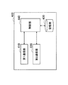
図5は、図4に示した管理ノード100の論理的な構成の一例を示すブロック図である。図5を参照すると、管理ノード100は、通信部110、データベース入出力部120、記憶部130、及び制御部140を備える。
[2-2. Example of management node configuration]
(Description of each functional block)
FIG. 5 is a block diagram illustrating an example of a logical configuration of the
通信部110は、第1の通信サービスの所定の通信方式に従い、アンテナ、RF回路、及びベースバンド回路等を含み得る通信インタフェースを用いて、一次利用ノード104との間で無線信号を送受信する。また、通信部110は、後にさらに説明するように、端末装置200から当該端末装置200の位置データを受信し、受信した位置データを制御部140へ出力する。
The
データベース入出力部120は、制御部140によるデータベース106へのアクセスを仲介する。即ち、データベース入出力部120は、制御部140からの要求に応じて一次利用ノード104の位置を表す位置データをデータベース106から取得し、取得した位置データを制御部140へ出力する。また、データベース入出力部120は、新たに一次システム102に加入した一次利用ノード104から通信部110を介して位置データが受信されると、その位置データをデータベース106に登録する。さらに、データベース入出力部120は、外部装置からの問い合わせに応じてデータベース106に記憶されている位置データを取得して出力してもよい。
The database input /
記憶部130は、例えばハードディスク又は半導体メモリなどの記録媒体を用いて、管理ノード100の各部の動作のために使用されるプログラム及びデータを記憶している。さらに、本実施形態において、記憶部130は、上述した干渉制御モデルに従った送信電力の計算に必要とされる各種パラメータを記憶する。記憶部130に記憶されるパラメータには、例えば、第1の通信サービスにおいて要求される無線信号の品質に関するパラメータ(例えば、要求される無線信号の受信レベル、及び信号対干渉及び雑音比)、及び第1の通信サービスにおける干渉又は雑音レベルに関するパラメータが含まれ得る。なお、これらパラメータの値は、動的に更新されてもよい。例えば、要求される無線信号の品質の値は、一次利用ノードに提供されるべきアプリケーションの種類などに応じて動的に更新され得る。また、例えば、干渉又は雑音レベルの値は、通信部110を介したセンシングにより動的に更新され得る。
The
制御部140は、例えばCPU(Central Processing Unit)などの制御装置を用いて、管理ノード100の機能全般を制御する。また、本実施形態において、制御部140は、端末装置200が第1の通信サービスに割当てられた周波数帯を二次利用する場合に、上述した干渉制御モデルに従って第2の通信サービスに許容する送信電力を決定する。制御部140が行う送信電力決定処理については、後により具体的に説明する。さらに、制御部140は、2以上の第2の通信サービスが存在する場合には、決定した送信電力を当該2以上の第2の通信サービスに分配する。制御部140が行う送信電力分配処理については、後により具体的に説明する。そして制御部140は、決定し又は分配した送信電力値を通信部110を介して各端末装置200に通知する。
The
(送信電力決定処理の流れ)
図6は、管理ノード100の制御部140により第2の通信サービスに許容する送信電力を決定するための送信電力決定処理の流れの一例を示すフローチャートである。
(Transmission power decision process flow)
FIG. 6 is a flowchart illustrating an example of a flow of transmission power determination processing for determining the transmission power allowed for the second communication service by the
図6を参照すると、まず、制御部140は、通信部110を介して、端末装置200から当該端末装置200の位置データを受信する(ステップS102)。本明細書において、位置データとは、例えば、GPS機能を用いて測定される緯度及び経度の値、又は到来方向推定アルゴリズムなどを応用して測定される所定の基準点を原点とした座標値などを含んでよい。また、制御部140は、端末装置200の位置データだけではなく、各二次利用ノード204の位置データを端末装置200から受信してもよい。
Referring to FIG. 6, first, the
次に、制御部140は、データベース入出力部120を介して、データベース106から一次利用ノードの位置データを取得する。また、制御部140は、記憶部130から必要なパラメータを取得する(ステップS104)。なお、図2Aに示した例のように、OFDMA方式のアップリンクチャネルが二次利用される場合には、被干渉ノードは基地局のみである。そのため、かかる場合には、ステップS104において、制御部140は、一次利用ノードの位置データとして基地局である管理ノード100の位置データのみを取得すればよい。また、ステップS104における必要なパラメータとは、例えば、上述した第1の通信サービスにおいて要求される無線信号の品質、及び第1の通信サービスにおける干渉若しくは雑音レベル(又はこれらレベルを計算するためのパラメータ)などに相当する。
Next, the
次に、制御部140は、ステップS102において受信し、ステップS104において取得した位置データ及びパラメータに基づいて、第2の通信サービスに許容される干渉電力を決定する(ステップS106)。より具体的には、制御部140は、例えば、上述した干渉制御モデルにおける式(9)に従って、第2の通信サービスに許容される干渉電力を決定することができる。その際、例えば、第1の通信サービスにおいて要求される無線信号の品質は、式(9)のPrx_primary,primary/SINRrequiredの項に対応する。また、干渉又は雑音レベルは式(9)のNPrimaryの項に対応する。さらに、式(9)の経路損失Lpath_tx_secondary,iの値は、一次利用ノードの位置データ及び各端末装置200の位置データから導かれる距離dを用いて、式(6)に従ってそれぞれ算出され得る。なお、制御部140は、例えば、個々の経路損失Lpath_tx_secondary,iの値を位置データから算出する代わりに、ステップS102において各端末装置200から個々の経路損失Lpath_tx_secondary,iの値を受信してもよい。経路損失Lpath_tx_secondary,iの値は、例えば、基地局からのダウンリンク信号の送信電力値と各端末装置200における当該ダウンリンク信号の受信レベルとの差として計算され得る。
Next, the
次に、制御部140は、送信電力の値を分配する必要があるか否かを判定する(ステップS108)。例えば、図4に例示したように、2以上の端末装置200により二次利用が行われる場合には、制御部140は、送信電力の値を当該2以上の端末装置200の間で分配する必要があると判定される。その場合、処理はステップS110へ移動し、制御部140により送信電力分配処理が行われる(ステップS110)。一方、例えば二次利用を行う端末装置200が1つのみ存在し、送信電力の値を分配する必要がない場合には、ステップS110はスキップされ得る。
Next, the
そして、制御部140は、決定され又は分配された送信電力の値を、通信部110を介して各端末装置200へ通知する(ステップ112)。なお、このとき、制御部140は、周波数帯の二次利用に際して二次利用ノードが順守すべきポリシー(例えば送信スペクトラムマスク、変調方法など)などの追加情報を、送信電力の値と共に各端末装置200へ通知してもよい。その後、端末装置200と各二次利用ノード204との間で、第2の通信サービスが開始され得る。
Then, the
(送信電力分配処理の流れ)
図7は、2以上の端末装置200が存在する場合、即ち、同一のセル内で2以上の第2の通信サービスが運用される場合の、管理ノード100の制御部140による送信電力分配処理の流れの一例を示すフローチャートである。
(Transmission power distribution process flow)
FIG. 7 illustrates the transmission power distribution process by the
図7を参照すると、まず、制御部140は、図6のステップS106において決定された許容される干渉電力に応じた送信電力を、第1の基準に従って分配する(ステップS202)。次に、制御部140は、ステップS202と同じ干渉電力に応じた送信電力を、第2の基準に従って分配する(ステップS204)。ここでの第1の基準及び第2の基準は、例えば、それぞれ上述した均等型の送信電力分配基準及び非均等型の送信電力分配基準であってよい。
Referring to FIG. 7, first,
次に、制御部140は、第1の基準に従って分配された送信電力、及び第2の基準に従って分配された送信電力を、所定の評価条件により評価する(ステップS206)。所定の評価条件とは、例えば、結果的に全ての端末装置200に与えられる合計通信容量であってもよい。その場合、合計通信容量Cは、次式に従って評価され得る。
Next, the
ここで、Ptx_secondary,iはi番目の端末装置200に分配された送信電力、Niはi番目の端末装置200の雑音レベルを表す。
Here, P tx_secondary, i is the i-th terminal transmission power distributed to the 200, N i denotes the noise level of the i th
また、制御部140は、式(13)において、n個の端末装置200のうち、優先度が高い端末装置200のみを通信容量の集計の対象としてもよい。ここでの優先度とは、例えば、第2の通信サービスの種類又は内容などによって与えられ得る。例えば、動画配信又は通信型のゲームなど、低遅延が要求されるサービスについて高い優先度が定義されてもよい。また、一定のサービス品質が保証されるようにサービス料が高く設定されたサービスについて高い優先度が定義されてもよい。そして、当該優先度は、例えば、図6のステップS102において、端末装置200の位置データと共に受信され得る。
Moreover, the
また、制御部140は、ステップS206において、式(13)のような通信容量の代わりに、分配された送信電力を使用して確立することのできる第2の通信サービスのリンクの総数を評価してもよい。その場合、まず、各端末装置200に分配された送信電力に応じて、通信を希望する個々の二次利用ノードのペアが通信を確立することができるか否かが判定される。そして、通信を確立することができると判定されたリンクの数が、第2の通信サービスのリンクの総数として集計され得る。
Further, in step S206, the
次に、制御部140は、ステップS206で評価した通信容量又はリンク総数を比較することにより、第1の基準と第2の基準のいずれが適しているかを判定する(ステップS208)。例えば、第1の基準に従って分配した送信電力の方が、第2の基準に従って分配した送信電力よりも多くの通信容量を達成できる場合には、第1の基準の方が適していると判定され得る。また、第2の基準に従って分配した送信電力の方が、第1の基準に従って分配した送信電力よりも多くの通信容量を達成できる場合には、第2の基準の方が適していると判定され得る。ここで、第1の基準の方が適していると判定された場合には、処理はステップS210へ進む。一方、第2の基準の方が適していると判定された場合には、処理はステップS212へ進む。
Next, the
ステップS210では、より適していると判定された第1の基準に従って分配された送信電力が、各端末装置200に割当てられる(ステップS210)。一方、ステップS212では、より適していると判定された第2の基準に従って分配された送信電力が、各端末装置200に割当てられる(ステップS212)。そして、図7に示した送信電力分配処理は終了する。 In step S210, the transmission power distributed according to the first criterion determined to be more suitable is allocated to each terminal device 200 (step S210). On the other hand, in step S212, transmission power distributed according to the second criterion determined to be more suitable is allocated to each terminal device 200 (step S212). Then, the transmission power distribution process shown in FIG. 7 ends.
なお、ここでは、特に均等型と非均等型とに相当し得る第1の基準と第2の基準とを、通信容量又は確立できるリンク数の観点で評価する例について説明した。しかしながら、かかる例に限定されず、例えば、均等型及び非均等型以外の送信電力分配基準が採用されてもよい。また、3つ以上の送信電力分配基準について評価がなされてもよい。 Note that, here, an example has been described in which the first standard and the second standard that can correspond to the uniform type and the non-uniform type are evaluated in terms of communication capacity or the number of links that can be established. However, the present invention is not limited to this example. For example, transmission power distribution standards other than the uniform type and the non-uniform type may be adopted. Also, evaluations may be made for three or more transmission power distribution criteria.
[2−3.端末装置の構成例]
(各機能ブロックの説明)
図8は、図4に示した端末装置200の論理的な構成の一例を示すブロック図である。図8を参照すると、端末装置200は、第1通信部210、第2通信部220、記憶部230、及び制御部240を備える。本実施形態において、端末装置200は、第1通信部210を介して管理ノード100との間で通信できると共に、第2通信部220を介して第2の通信サービスのための無線信号を送受信することができる。
[2-3. Example of terminal device configuration]
(Description of each functional block)
FIG. 8 is a block diagram illustrating an example of a logical configuration of the
第1通信部210は、所定の通信方式に従い、管理ノード100との間で通信を行う。第1通信部210と管理ノード100との間の通信に使用されるチャネルは、例えば、制御用チャネルであるコグニティブパイロットチャネル(CPC)などであってもよい。CPCは、例えば、既存の通信システム(例えば一次システム102)においてCPC情報が外挿されるインバンドCPC、又はCPC情報が内挿される専用のチャネルであるアウトバンドCPCを含み得る。
The
例えば、第1通信部210は、周波数帯の二次利用の開始等の指示(ユーザによる指示操作又は他のノードからの要求)に応じて、自装置の位置を表す位置データを管理ノード100へ送信する。その後、第1通信部210は、上述した手法に従って決定された許容送信電力の値を管理ノード100から受信し、制御部240へ出力する。
For example, the
第2通信部220は、所定の通信方式に従い、二次利用ノード204との間で無線信号を送受信する。例えば、端末装置200が第2の通信サービスのコーディネータとして動作する場合には、第2通信部220は、まず、第1の通信サービスの無線信号をセンシングし、アップリンクチャネルの同期を獲得する。そして、第2通信部220は、同期を獲得した当該アップリンクチャネルを使用して、周囲の二次利用ノード204へ定期的にビーコンを送信する。このとき、第2通信部220により使用される送信電力は、制御部240からの制御を受けて、一次利用ノードへ実質的な干渉を与えない範囲内に制限される。
The
なお、第1通信部210と管理ノード100との間の通信リンクが無線リンクである場合には、第1通信部210及び第2通信部220は、アンテナ、RF回路、及びベースバンド回路等を含み得る物理的に同一の通信インタフェースを共用してもよい。第1通信部210と管理ノード100との間の通信リンクは、バックホールリンクと呼ばれる場合がある。
When the communication link between the
記憶部230は、例えばハードディスク又は半導体メモリなどの記録媒体を用いて、端末装置200の各部の動作のために使用されるプログラム及びデータを記憶している。さらに、本実施形態において、記憶部230は、第2の通信サービスの運用及び送信電力の制御のための各種パラメータを記憶する。記憶部230に記憶されるパラメータには、例えば、自装置(及び、必要に応じて第2の通信サービスに加入する他の二次利用ノード)の位置データ、並びに管理ノード100から通知された許容送信電力、スペクトラムマスク、及び変調方法などが含まれ得る。
The
制御部240は、例えばCPUなどの制御装置を用いて、端末装置200の機能全般を制御する。例えば、本実施形態において、制御部240は、第2通信部220により無線信号の送信に使用される送信電力の値を、管理ノード100から通知された許容送信電力の範囲内に制御する。
The
(送信電力制御処理の流れ)
図9は、端末装置200による送信電力制御処理の流れの一例を示すフローチャートである。
(Transmission power control process flow)
FIG. 9 is a flowchart illustrating an example of a flow of transmission power control processing by the
図9において、例えば二次利用の開始の指示が検知されると、第1通信部210は、管理ノード100へ端末装置200の位置データを送信する(ステップS302)。このとき、端末装置200の位置データだけではなく、他の二次利用ノード204の位置データが管理ノード100へ送信されてもよい。
In FIG. 9, for example, when an instruction to start secondary usage is detected, the
次に、第1通信部210は、上述した干渉制御モデルに従って決定された許容送信電力の値を、管理ノード100から受信する(S304)。このとき、例えば、許容送信電力に加えて、例えば送信スペクトラムマスク及び変調方法などの追加情報も共に受信され得る。
Next, the
そして、制御部240は、ステップS304において受信された許容送信電力の範囲内に第2通信部220に使用される送信電力を制御しながら、第2の通信サービスを開始する(ステップS306)。なお、第2の通信サービスを開始する際、制御部240は、例えば、端末装置200から周囲の二次利用ノードへ送信されるビーコンに、当該第2の通信サービスに割当てられた上記許容送信電力の値を含めてもよい。そうすることにより、第2の通信サービスに加入する二次利用ノードも、一次利用ノードへ実質的な干渉を与えないように自ら使用する送信電力を適応させることができる。
And the
[2−4.第1の実施形態のまとめ]
ここまで、図4〜図9を用いて、本発明の第1の実施形態について説明した。本実施形態によれば、第1の通信サービスに割当てられた周波数帯を二次利用する第2の通信サービスに割当てられる送信電力(即ち、許容送信電力)が、上述した干渉制御モデルに従い、データベース106にアクセス可能な一次利用ノードである管理ノード100により決定される。そして、決定された許容送信電力は、管理ノード100から、第2の通信サービスのコーディネータの役割を有する二次利用ノードである端末装置200へ通知される。それにより、端末装置200は、第2の通信サービスに使用する送信電力を、一次システム102に与える干渉が許容される範囲内となるように抑制しながら、適応的に制御することができる。
[2-4. Summary of First Embodiment]
Up to this point, the first embodiment of the present invention has been described with reference to FIGS. According to the present embodiment, the transmission power allocated to the second communication service that secondarily uses the frequency band allocated to the first communication service (that is, the allowable transmission power) is the database according to the above-described interference control model. It is determined by the
また、上述した干渉制御モデルによれば、許容送信電力は、第1の通信サービスにおいて要求される無線信号の品質、第1の通信サービスにおける干渉又は雑音レベル、及び1以上の二次利用ノードについての通信経路上の経路損失に基づいて、被干渉ノードにおける干渉が許容される範囲内となるように決定される。それにより、一部の一次利用ノードにおいて局所的に一次信号の受信が困難となるリスクをなくす(又は少なくとも緩和する)ことができる。 Further, according to the above-described interference control model, the allowable transmission power is the radio signal quality required in the first communication service, the interference or noise level in the first communication service, and one or more secondary usage nodes. Based on the path loss on the communication path, the interference at the interfered node is determined to be within an allowable range. Thereby, it is possible to eliminate (or at least mitigate) the risk of difficulty in receiving the primary signal locally at some primary usage nodes.
また、上記通信経路上の経路損失は、一次利用ノードの位置と二次利用ノードの位置とに基づいて、動的に計算され得る。それにより、端末装置200の位置が変化した場合でも、被干渉ノードにおける干渉が許容される範囲内となるように適応的に許容送信電力を決定することができる。
The path loss on the communication path can be dynamically calculated based on the position of the primary usage node and the position of the secondary usage node. Thereby, even when the position of the
さらに、本実施形態によれば、2以上の第2の通信サービスが運用される場合には、上述した干渉制御モデルに従って決定される許容干渉電力に応じた送信電力が、第1の基準と第2の基準のうちより適切な基準に従って各第2の通信サービスに分配される。第1の基準と第2の基準とは、例えば、上述した均等型の分配基準と非均等型の分配基準であってよい。このうち、均等型の分配基準によれば、ユーザの視点から公平かつ明瞭な形で通信機会(通信容量又は通信リンク数など)を分配することができる。また、非均等型の分配基準によれば、被干渉ノードとの距離が遠い二次利用ノードに高い送信電力が割当てられるため、全体としての通信範囲が最大化されるように送信電力を分配することができる。さらに、干渉マージン低減型の分配基準によれば、一次利用ノードに干渉を与えるリスクをより低減することができる。 Further, according to the present embodiment, when two or more second communication services are operated, the transmission power according to the allowable interference power determined according to the above-described interference control model is the first reference and the first It is distributed to each second communication service according to a more appropriate one of the two criteria. The first standard and the second standard may be, for example, the above-described uniform distribution standard and non-uniform distribution standard. Among these, according to the uniform distribution standard, communication opportunities (communication capacity or the number of communication links) can be distributed in a fair and clear manner from the user's viewpoint. Also, according to the non-uniform distribution standard, high transmission power is allocated to the secondary usage node that is far from the interfered node, so that the transmission power is distributed so that the entire communication range is maximized. be able to. Furthermore, according to the interference margin reduction type distribution criterion, it is possible to further reduce the risk of causing interference to the primary usage node.
また、第1の基準と第2の基準のうちより適切な上記基準とは、例えば、分配された送信電力を使用して結果的に達成される合計通信容量がより多い基準であってもよい。その場合、周波数帯の二次利用により有効活用される通信容量を最大化することができる。 In addition, the more appropriate one of the first standard and the second standard may be a standard that has a higher total communication capacity that is achieved as a result using, for example, distributed transmission power. . In this case, the communication capacity that can be effectively utilized by secondary use of the frequency band can be maximized.
また、第1の基準と第2の基準のうちより適切な上記基準とは、例えば、分配された送信電力を使用して結果的に達成される通信容量のうち、優先度の高い第2の通信サービスに係る合計通信容量がより多い基準であってもよい。その場合、特に、個々のアプリケーションの要求、又はユーザにより合意されたQoSの要件などが充足されるように、周波数帯の二次利用による通信容量を選択的に高めることができる。 Further, the more appropriate standard among the first standard and the second standard is, for example, the second highest priority among the communication capacities achieved as a result using the distributed transmission power. The criterion may be a higher total communication capacity related to the communication service. In that case, in particular, the communication capacity by secondary use of the frequency band can be selectively increased so that the requirements of individual applications or QoS requirements agreed by the user are satisfied.
また、第1の基準と第2の基準のうちより適切な上記基準とは、例えば、分配された送信電力を使用して結果的に確立することのできるリンク数がより多い基準であってもよい。その場合、周波数帯の二次利用により通信機会を得ることのできるユーザ数を最大化することができる。 Further, the more appropriate one of the first reference and the second reference may be a reference having a larger number of links that can be established as a result using, for example, distributed transmission power. Good. In that case, the number of users who can obtain a communication opportunity by secondary use of the frequency band can be maximized.
なお、本実施形態では、第2の通信サービスの開始の際に当該第2の通信サービスにおいて使用される送信電力が制御される例について説明した。しかしながら、第2の通信サービスの開始の後、例えば二次利用ノードが移動した場合又は二次利用ノードの数が変化した場合などに、図6、図7及び図9に示した各処理が実行されてもよい。 In the present embodiment, the example in which the transmission power used in the second communication service is controlled when the second communication service is started has been described. However, after the start of the second communication service, for example, when the secondary usage node moves or the number of secondary usage nodes changes, the processes shown in FIGS. 6, 7, and 9 are executed. May be.
また、本実施形態では、第1の通信サービスのアップリンクチャネルが二次利用される場合、即ち、第1の通信サービスの基地局のみを被干渉ノードとして考慮すればよい例について説明した。しかしながら、被干渉ノードが複数存在する場合にも本発明が適用可能であることは言うまでもない。 Further, in the present embodiment, an example has been described in which the uplink channel of the first communication service is secondarily used, that is, only the base station of the first communication service may be considered as an interfered node. However, it goes without saying that the present invention is also applicable when there are a plurality of interfered nodes.
[2−5.変形例]
上述した干渉制御モデルでは、一次利用ノードのうちの被干渉ノードにおける干渉が許容される範囲内に抑制されるように、第2の通信サービスのために許容される送信電力が決定された。一方、第2の通信サービスのために使用される送信電力は、二次利用ノードにおける通信品質をも考慮して決定されてもよい。
[2-5. Modified example]
In the interference control model described above, the transmission power allowed for the second communication service is determined so that the interference in the interfered node of the primary usage nodes is suppressed within the allowable range. On the other hand, the transmission power used for the second communication service may be determined in consideration of the communication quality in the secondary usage node.
1つの二次利用ノードを被干渉ノードとみなした場合に、その干渉が許容されるためには、次の関係式(14)が満たされていことが求められる。 When one secondary usage node is regarded as an interfered node, in order to allow the interference, it is required that the following relational expression (14) is satisfied.
ここで、SINRi_required_secondaryは、被干渉ノードであるi番目の二次利用ノードにおいて要求される最小のSINRを表す。SINRi_required_secondaryは、例えば、被干渉ノードの最小受信感度、又はQoSに応じて与えられる最小のSINRなどであってよい。また、Pi_rx_secondary,j_tx_secondaryは、j番目の二次利用ノードからi番目の二次利用ノードへ送信される第2の通信サービスの無線信号(二次信号)について要求される受信レベルを表す。また、Ii,primaryは第1の通信サービスの無線信号による干渉レベル、Ii,k(k≠i,k≠j)_tx_secondaryはi番目でもj番目でもない(即ち所望の通信リンクに関連しない)他の二次利用ノードからの二次信号による干渉レベルをそれぞれ表す。また、Niは、i番目の二次利用ノードに適用され得る雑音レベルを表す。なお、他の二次利用ノードからの二次信号による干渉レベルIi,k(k≠i,k≠j)_tx_secondaryは、所望の通信リンクに関連しない二次利用ノードの送信電力の総和からそれら二次利用ノードについての経路損失の総和を減ずることにより計算され得る。 Here, SINR i_required_secondary represents the minimum SINR required in the i-th secondary usage node that is the interfered node. The SINR i_required_secondary may be, for example, the minimum reception sensitivity of the interfered node or the minimum SINR given according to the QoS. Pi_rx_secondary, j_tx_secondary represents the reception level required for the radio signal (secondary signal) of the second communication service transmitted from the jth secondary usage node to the ith secondary usage node. Also, I i, primary is the interference level due to the radio signal of the first communication service, and I i, k (k ≠ i, k ≠ j) _tx_secondary is neither i-th nor j-th (that is, not related to the desired communication link). ) Represents interference levels due to secondary signals from other secondary usage nodes. N i represents a noise level that can be applied to the i-th secondary usage node. The interference level I i, k (k ≠ i, k ≠ j) _tx_secondary due to secondary signals from other secondary usage nodes is calculated from the total transmission power of secondary usage nodes not related to the desired communication link. It can be calculated by subtracting the total path loss for the secondary usage node.
従って、上述した第1の実施形態における管理ノード100は、例えば、図6に示した送信電力決定処理のステップS110において、各端末装置200に割当てられる送信電力が上記式(14)を満たすように、送信電力を分配してもよい。
Therefore, the
<3.第2の実施形態>
本発明の第1の実施形態では、第2の通信サービスに割当てられる送信電力は、一次利用ノードの位置データを保持するデータベースにアクセス可能な一次利用ノード(管理ノード)により決定された。これは、二次利用を行う端末装置(UE)の視点からは受動的な手法である。これに対し、二次利用を行う端末装置が必要なパラメータを取得し、第2の通信サービスのために許容される送信電力を能動的に決定することもできる。そこで、本節では、本発明の第2の実施形態として、二次利用を行う端末装置が能動的に許容される送信電力を決定する例について説明する。
<3. Second Embodiment>
In the first embodiment of the present invention, the transmission power allocated to the second communication service is determined by the primary usage node (management node) that can access the database holding the location data of the primary usage node. This is a passive method from the viewpoint of a terminal apparatus (UE) that performs secondary usage. On the other hand, the terminal device that performs secondary use can acquire necessary parameters and actively determine the transmission power allowed for the second communication service. Therefore, in this section, an example in which a terminal device that performs secondary usage determines actively allowable transmission power will be described as a second embodiment of the present invention.
[3−1.通信システムの概要]
図10は、本発明の第2の実施形態に係る通信システムの概要について説明するための説明図である。
[3-1. Overview of communication system]
FIG. 10 is an explanatory diagram for explaining an overview of a communication system according to the second embodiment of the present invention.
図10を参照すると、第1の通信サービスが運用される一次システム302、並びにそれぞれ第2の通信サービスが運用される二次システム402a及び402bが示されている。このうち、一次システム302は、管理ノード300及び複数の一次利用ノード104を含む。
Referring to FIG. 10, a
管理ノード300は、第1の通信サービスに割当てられた周波数帯の二次利用を管理する役割を有する一次利用ノードである。図10の例では、管理ノード300として基地局を示しているが、管理ノード300は、かかる例に限定されない。本実施形態において、管理ノード300は、一次システム302に含まれる一次利用ノードの位置を表す位置データを保持しているデータベース106にアクセスすることができる。
The
一方、二次システム402aは、端末装置400a及び複数の二次利用ノード204aを含む。同様に、二次システム402bは、端末装置400b及び複数の二次利用ノード204bを含む。
On the other hand, the
端末装置400(400a及び400b)は、第1の通信サービスに割当てられた周波数帯の二次利用を開始するために動作するコーディネータ(SSC)の役割を有する二次利用ノードである。即ち、端末装置400は、それぞれ、所定のスペクトラムポリシーに従って二次利用の可否を判断し、管理ノード100から必要なパラメータを取得して許容される送信電力を決定した後、二次利用ノード204と共に第2の通信サービスを開始する。端末装置400は、例えば、コグニティブ無線のためのエンジン(CE)として動作してもよい。
The terminal device 400 (400a and 400b) is a secondary usage node having the role of a coordinator (SSC) that operates to start secondary usage of the frequency band allocated to the first communication service. That is, each of the
[3−2.管理ノードの構成例]
図11は、図10に示した管理ノード300の論理的な構成の一例を示すブロック図である。図11を参照すると、管理ノード300は、通信部310、データベース入出力部120、記憶部130、及び制御部340を備える。
[3-2. Example of management node configuration]
FIG. 11 is a block diagram illustrating an example of a logical configuration of the
通信部310は、第1の通信サービスの所定の通信方式に従い、アンテナ、RF回路、及びベースバンド回路等を含み得る通信インタフェースを用いて、一次利用ノード104との間で無線信号を送受信する。また、通信部310は、後にさらに説明するように、データベース106に記憶されている一次利用ノード104の位置データ、及びデータベース106又は記憶部130に記憶されている送信電力の決定に使用されるパラメータを、端末装置400へ送信する。
The
制御部340は、例えばCPUなどの制御装置を用いて、管理ノード300の機能全般を制御する。また、本実施形態において、制御部340は、端末装置400が上述した干渉制御モデルに従って許容送信電力を決定する際に使用する上記位置データ及びパラメータを、通信部310(又は他のバックホールリンク)を介して端末装置400へ送信させる。位置データ及びパラメータの送信は、例えば、CPCなどの所定のチャネルを使用して定期的に行われてもよい。その代わりに、位置データ及びパラメータの送信は、例えば、端末装置400からの送信要求への応答として行われてもよい。
The
[3−3.端末装置の構成例]
(各機能ブロックの説明)
図12は、図10に示した端末装置400の論理的な構成の一例を示すブロック図である。図12を参照すると、端末装置400は、第1通信部410、第2通信部220、記憶部430、及び制御部440を備える。
[3-3. Example of terminal device configuration]
(Description of each functional block)
12 is a block diagram illustrating an example of a logical configuration of the
第1通信部410は、所定の通信方式に従い、管理ノード300から送信される上記データ及びパラメータを含む無線信号を受信する。第1通信部410と管理ノード300との間の通信に使用されるチャネルは、制御用のチャネルである上述したCPCなどであってもよい。
The
より具体的には、第1通信部410は、例えば周波数帯の二次利用の開始等の指示に応じて、管理ノード300から送信電力の決定に使用されるデータ及びパラメータの受信を試みる。送信電力の決定に使用されるデータ及びパラメータには、例えば、被干渉ノードの位置データ、並びに第1の通信サービスにおいて要求される無線信号の品質、及び第1の通信サービスにおける干渉又は雑音レベルなどが含まれ得る。また、送信電力の決定に使用されるデータには、他の二次利用ノードの位置を表す位置データが含まれていてもよい。そして、第1通信部410は、これらデータ及びパラメータを管理ノード300から受信すると、受信した当該データ及びパラメータを制御部440へ出力する。また、第1通信部410は、信号の受信環境が良好でないなどの理由で必要なデータ及びパラメータを受信できない場合には、その旨を制御部440へ通知する。
More specifically, the
記憶部430は、例えばハードディスク又は半導体メモリなどの記録媒体を用いて、端末装置400の各部の動作のために使用されるプログラム及びデータを記憶している。さらに、本実施形態において、記憶部430は、第2の通信サービスのための送信電力の決定及び送信電力の制御のための各種パラメータを記憶する。記憶部430に記憶されるパラメータには、例えば、自装置(及び、必要に応じて第2の通信サービスに加入する他の二次利用ノード)の位置データ、並びに管理ノード300から第1通信部410を介して受信される上記パラメータなどが含まれ得る。
The
制御部440は、例えばCPUなどの制御装置を用いて、端末装置400の機能全般を制御する。例えば、本実施形態において、制御部440は、第1の通信サービスに割当てられた周波数帯を二次利用する場合に、上述した干渉制御モデルに従って決定される許容干渉電力に応じて第2の通信サービスのための許容送信電力を決定する。その際、制御部440は、管理ノード300からの無線信号を受信できず一次利用ノードの最新の位置データ及び必要なパラメータを取得できない場合には、一次利用ノードに干渉を与える可能性を低減するためのマージンを算入して許容送信電力を決定する。ここでの送信電力決定処理については、後により具体的に説明する。そして、制御部440は、第2通信部220により無線信号の送信に使用される送信電力の値を、決定した許容送信電力の範囲内に制御する。
The
(送信電力決定処理の流れ)
図13は、制御部440が第2の通信サービスに許容される送信電力を決定するための送信電力決定処理の流れの一例を示すフローチャートである。
(Transmission power decision process flow)
FIG. 13 is a flowchart illustrating an example of a flow of transmission power determination processing for the
図13を参照すると、まず、制御部440は、通信部410を介して管理ノード300から無線信号を受信することが可能か否かを判定する(ステップS402)。ここで、管理ノード300からの無線信号を受信できる場合には、処理はステップS404へ進む。一方、管理ノード300からの無線信号を受信できない場合には、処理はステップS408へ進む。
Referring to FIG. 13, first, the
ステップS404では、制御部440は、通信部410を介して管理ノード300から受信された被干渉ノードとなる一次利用ノードの位置データを取得する。また、制御部440は、同様に管理ノード300から受信されたパラメータを取得する(ステップS404)。なお、図2Aに示した例のように、OFDMA方式のアップリンクチャネルが二次利用される場合には、被干渉ノードは基地局のみである。そのため、かかる場合には、制御部440は、一次利用ノードの位置データとして基地局である管理ノード300の位置データのみを取得すればよい。また、ステップS404における必要なパラメータとは、例えば、上述した第1の通信サービスにおいて要求される無線信号の品質、及び第1の通信サービスにおける干渉若しくは雑音レベル(又はこれらレベルを計算するためのパラメータ)などに相当する。
In step S <b> 404, the
次に、制御部440は、ステップS404において受信された位置データ及びパラメータに基づいて、第2の通信サービスに許容される干渉電力に応じた送信電力を決定する(ステップS406)。より具体的には、制御部440は、例えば、上述した干渉制御モデルにおける式(9)に従って、第2の通信サービスに許容される干渉電力に応じた送信電力を決定することができる。その際、例えば、第1の通信サービスにおいて要求される無線信号の品質は、式(9)のPrx_primary,primary/SINRrequiredの項に対応する。また、干渉又は雑音レベルは式(9)のNPrimaryの項に対応する。さらに、式(9)の経路損失Lpath_tx_secondary,iの値は、一次利用ノードの位置データ及び端末装置400の位置データから導かれる距離dを用いて、式(6)に従って算出され得る。なお、制御部440は、例えば、経路損失Lpath_tx_secondary,iの値を位置データから算出する代わりに、経路損失Lpath_tx_secondary,iの値を基地局からのダウンリンク信号の送信電力値と当該ダウンリンク信号の受信レベルとの差として計算してもよい。さらに、制御部440は、他の第2の通信サービスが存在している場合には、均等型の式(10)、又は非均等型の式(11)に従って、送信電力を分配してもよい。
Next, the
一方、管理ノード300からの無線信号を受信できない場合には、ステップS408において、制御部440は、送信電力を決定するための位置データ及びパラメータを記憶部430から取得する(ステップS408)。例えば、制御部440は、管理ノード300との間の通信が可能となった時に第1通信部を介して被干渉ノードの位置データ及び必要なパラメータを受信し、それらを後の使用のために記憶部430に記憶させておくことができる。また、例えば、二次利用の対象とする第1の通信サービスの種類が予めいくつかの候補に限定されている場合には、当該第1の通信サービスにおいて要求される無線信号の品質などを表すパラメータを既定値として記憶部430に記憶させておいてもよい。
On the other hand, when the radio signal from the
次に、制御部440は、ステップS408において取得された位置データ及びパラメータに基づいて、第2の通信サービスに許容される干渉電力に応じた送信電力を決定する(ステップS410)。但し、この場合、送信電力の決定に使用できるパラメータは、最新のものではない可能性がある。そのため、制御部440は、一次利用ノードに干渉を与える可能性を低減するために、送信電力の値に所定のマージンを算入する。より具体的には、制御部440は、例えば、上述した与干渉マージン低減型の式(12)に従って送信電力を決定することができる。式(12)におけるNestimaionの値は、例えば、第2の通信サービスへの加入が見込まれる二次利用ノード204の数に応じて、余剰数を含むように決定される。
Next, the
その後、制御部440による送信電力決定処理は終了する。そして、端末装置400と各二次利用ノード204との間で、決定された許容送信電力の範囲内の電力レベルを使用しながら、第2の通信サービスが開始される。
Thereafter, the transmission power determination process by the
[3−4.第2の実施形態のまとめ]
ここまで、図10〜図13を用いて、本発明の第2の実施形態について説明した。本実施形態によれば、第1の通信サービスに割当てられた周波数帯を二次利用する第2の通信サービスにおいて許容される送信電力が、上述した干渉制御モデルに従い、第2の通信サービスのコーディネータの役割を有する端末装置400により決定される。それにより、端末装置400は、第2の通信サービスに使用する送信電力を能動的に決定した上で、一次システム302に与える干渉を抑制しながら送信電力を制御することができる。
[3-4. Summary of Second Embodiment]
Up to this point, the second embodiment of the present invention has been described with reference to FIGS. According to the present embodiment, the transmission power allowed in the second communication service that secondarily uses the frequency band allocated to the first communication service is in accordance with the above-described interference control model, and the coordinator of the second communication service. It is determined by the
また、端末装置400が管理ノード300からの無線信号を受信できず一次利用ノードの最新の位置データを取得できない場合には、送信電力の範囲は、一次利用ノードに干渉を与える可能性を低減するためのマージンを算入して決定される。それにより、端末装置400がシャドウイング(遮蔽)又はフェージングなどの影響により信号の受信状況が比較的良好でない領域に位置している場合であっても、端末装置400は、自律的かつ安全に周波数帯の二次利用を開始することができる。
In addition, when the
また、上述した与干渉マージン低減型の手法によれば、上記マージンは、二次利用ノードの実際の数ではなく、余剰数を含めて見積もられた想定の値に応じて決定される。それにより、第2の通信サービスに加入する二次利用ノードが予測される範囲内で増加した場合にも、第1の通信サービスの品質が低下することが防がれる。 Further, according to the above-described interference margin reduction method, the margin is determined according to an assumed value estimated including the surplus number, not the actual number of secondary usage nodes. Thereby, even when the number of secondary usage nodes that subscribe to the second communication service increases within the predicted range, it is possible to prevent the quality of the first communication service from deteriorating.
[4.TVバンドへの適用]
図14は、上述した第1又は第2の実施形態のTVバンドへの適用について説明するための説明図である。図14の例において、一次利用ノード900は、テレビジョン放送の放送局である。また、一次利用ノード910a〜910cは、テレビジョン放送の受信局である。一次利用ノード900は、境界902又は904の内部に位置する一次利用ノード910a〜910cに、周波数帯F1上でデジタルTV放送サービスを提供する。境界902の内部は、デジタルTV放送サービスのサービスエリアである。また、斜線で示された境界902と境界904との間の領域は、周波数帯の二次利用が制限されるガードエリアである。一方、境界904と境界906との間の領域はTVホワイトスペースである。二次利用ノード920a〜920cは、かかるTVホワイトスペースに位置し、例えば周波数帯F1とは異なる周波数帯F3上で第2の通信サービスを運用する。しかし、例えば第1の通信サービスの周波数帯F1と第2の通信サービスの周波数帯F3との間にガードバンドを設けたとしても、例えば位置P0において二次システムのみならず一次システムへの致命的な干渉が生じるリスクがある。このようなリスクは、例えば、ガードエリアの幅を拡張することにより低減される。しかし、ガードエリアの幅を拡張することは、周波数帯の二次利用機会の減少を意味する。これに対し、上述した第1又は第2の実施形態に従って第2の通信サービスの送信電力を制御することにより、ガードエリアの幅を過度に拡張することなく、一次システムに与える干渉を許容される範囲内に抑制することができる。
[4. Application to TV band]
FIG. 14 is an explanatory diagram for explaining application of the above-described first or second embodiment to a TV band. In the example of FIG. 14, the
なお、本明細書において説明した第1及び第2の実施形態に係る一連の処理をハードウェアで実現するかソフトウェアで実現するかは問わない。一連の処理又はその一部をソフトウェアで実行させる場合には、ソフトウェアを構成するプログラムが、例えばROM(Read Only Memory)などの記録媒体に予め記憶され、RAM(Random Access Memory)に読み込まれた後、CPUを用いて実行される。 Note that it does not matter whether a series of processing according to the first and second embodiments described in this specification is realized by hardware or software. When a series of processes or a part thereof is executed by software, a program constituting the software is stored in advance in a recording medium such as a ROM (Read Only Memory) and read into a RAM (Random Access Memory). , Executed using a CPU.
本明細書において説明した各実施形態の要旨は、上述したように様々な二次利用の形態に広く適用可能である。例えば、上述したように、第1の通信サービスのスペクトラムホールをカバーするためのリレーノード又はフェムトセルの運用は、周波数帯の二次利用の一形態ということができる。また、互いに共通する周波数帯を使用するマクロセル、RRH(Remote Radio Head)、Hotzone、リレーノード又はフェムトセルなどの相互の関係も、周波数帯の二次利用の一形態(例えば、ヘテロジーニアスネットワークなど)を形成し得る。 The gist of each embodiment described in the present specification can be widely applied to various secondary usage modes as described above. For example, as described above, the operation of the relay node or the femtocell for covering the spectrum hole of the first communication service can be said to be a form of secondary use of the frequency band. In addition, the mutual relationship between a macro cell, a RRH (Remote Radio Head), a Hotzone, a relay node, or a femto cell using a common frequency band is also a form of secondary use of the frequency band (for example, heterogeneous network). Can be formed.
以上、添付図面を参照しながら本発明の好適な実施形態について詳細に説明したが、本発明はかかる例に限定されない。本発明の属する技術の分野における通常の知識を有する者であれば、特許請求の範囲に記載された技術的思想の範疇内において、各種の変更例または修正例に想到し得ることは明らかであり、これらについても、当然に本発明の技術的範囲に属すものと了解される。 The preferred embodiments of the present invention have been described in detail above with reference to the accompanying drawings, but the present invention is not limited to such examples. It is obvious that a person having ordinary knowledge in the technical field to which the present invention pertains can come up with various changes or modifications within the scope of the technical idea described in the claims. These are naturally understood to belong to the technical scope of the present invention.
100,300 管理ノード
102,302 一次システム
104 一次利用ノード
106 データベース
110,310 通信部
120 データベース入出力部
130 記憶部
140,340 制御部
200,400 端末装置(二次利用ノードのうちのコーディネータ)
202,402 二次システム
204 二次利用ノード
210,410 第1通信部
220 第2通信部
230,430 記憶部
240,440 制御部
100, 300
202, 402 Secondary system 204
Claims (10)
前記第1の通信サービスにおいて要求される無線信号の品質と、前記第1の通信サービスにおける干渉レベル又は雑音レベルと、前記第2の通信サービスの無線信号を送信する1以上の二次利用ノードについての通信経路上の経路損失とに基づいて、前記許容される送信電力を決定するステップ、
を含み、
前記許容される送信電力の決定の際に前記コーディネータの役割を有するノードが前記第1の通信サービスの無線信号を受信する一次利用ノードの位置を表す位置データを取得できない場合には、前記許容される送信電力は、前記一次利用ノードに干渉を与える可能性を低減するための、前記二次利用ノードの想定される数に依存するマージンを算入して決定される、
方法。 Performed by a node having a role of a coordinator of the second communication service for determining transmission power allowed for the second communication service that secondarily uses the frequency band allocated to the first communication service A method,
One or more secondary usage nodes transmitting radio signal quality required in the first communication service, interference level or noise level in the first communication service, and radio signal of the second communication service Determining the allowable transmission power based on path loss on the communication path of:
Only including,
When the node having the role of the coordinator cannot obtain the position data indicating the position of the primary usage node that receives the radio signal of the first communication service when determining the allowable transmission power, the allowable The transmission power is determined by including a margin depending on the assumed number of secondary usage nodes to reduce the possibility of causing interference to the primary usage node.
Method.
前記第1の通信サービスの無線信号を受信する一次利用ノードの位置を表す位置データを保持しているデータベースから当該位置データを取得できる場合に、当該位置データを取得するステップと、
前記位置データにより表される前記一次利用ノードの位置、及び前記1以上の二次利用ノードの位置に基づいて、前記1以上の二次利用ノードについての通信経路における前記経路損失を算出するステップと、
をさらに含む、請求項1又は請求項2に記載の方法。 The method
Obtaining the position data when the position data can be obtained from a database holding position data representing the position of the primary usage node that receives the wireless signal of the first communication service; and
Calculating the path loss in the communication path for the one or more secondary usage nodes based on the position of the primary usage node represented by the location data and the positions of the one or more secondary usage nodes; ,
The method according to claim 1, further comprising:
をさらに含む、請求項3に記載の方法。 Notifying one of the one or more secondary usage nodes of the determined allowable transmission power from the node having the role of coordinator ;
The method of claim 3, further comprising:
前記第2の通信サービスに許容される送信電力を決定する制御部と、
を備え、
前記制御部は、
前記第1の通信サービスにおいて要求される無線信号の品質と、前記第1の通信サービスにおける干渉レベル又は雑音レベルと、前記第2の通信サービスの無線信号を送信する1以上の二次利用ノードについての通信経路上の経路損失とに基づいて、前記許容される送信電力を決定し、
前記許容される送信電力の決定の際に前記第1の通信サービスの無線信号を受信する一次利用ノードの位置を表す位置データを取得できない場合には、前記許容される送信電力を、前記一次利用ノードに干渉を与える可能性を低減するための、前記二次利用ノードの想定される数に依存するマージンを算入して決定する、
通信装置。 A communication unit capable of transmitting a radio signal of the second communication service that secondarily uses the frequency band assigned to the first communication service;
A control unit for determining transmission power allowed for the second communication service;
With
The controller is
One or more secondary usage nodes transmitting radio signal quality required in the first communication service, interference level or noise level in the first communication service, and radio signal of the second communication service based of on the path loss on the communication path, and determining the acceptable transmit power,
When the location data representing the location of the primary usage node that receives the radio signal of the first communication service cannot be obtained at the time of determining the allowable transmission power, the allowable transmission power is used as the primary usage. Determining by including a margin depending on the assumed number of secondary usage nodes to reduce the possibility of causing interference to the nodes;
Communication device.
前記第1の通信サービスにおいて要求される無線信号の品質と、前記第1の通信サービスにおける干渉レベル又は雑音レベルと、前記第2の通信サービスの無線信号を送信する1以上の二次利用ノードについての通信経路上の経路損失とに基づいて、前記第2の通信サービスに許容される送信電力を決定する制御部、
として機能させ、
前記制御部は、前記許容される送信電力の決定の際に前記第1の通信サービスの無線信号を受信する一次利用ノードの位置を表す位置データを取得できない場合には、前記許容される送信電力を、前記一次利用ノードに干渉を与える可能性を低減するための、前記二次利用ノードの想定される数に依存するマージンを算入して決定する、
プログラム。 A computer that controls a communication device including a communication unit capable of transmitting a radio signal of a second communication service that secondarily uses a frequency band assigned to the first communication service;
One or more secondary usage nodes transmitting radio signal quality required in the first communication service, interference level or noise level in the first communication service, and radio signal of the second communication service A control unit that determines transmission power allowed for the second communication service based on a path loss on the communication path of
To function as,
When the control unit cannot acquire position data indicating the position of the primary usage node that receives the radio signal of the first communication service when determining the allowable transmission power, the allowable transmission power Is determined by including a margin that depends on the assumed number of secondary usage nodes to reduce the possibility of interference to the primary usage nodes.
program.
前記第2の通信サービスに許容される送信電力を決定する制御部と、
を備え、
前記制御部は、
前記第1の通信サービスにおいて要求される無線信号の品質と、前記第1の通信サービスにおける干渉レベル又は雑音レベルと、1以上の二次利用ノードについての通信経路上の経路損失とに基づいて、前記許容される送信電力を決定し、
前記許容される送信電力の決定の際に前記第1の通信サービスの無線信号を受信する一次利用ノードの位置を表す位置データを取得できない場合には、前記許容される送信電力を、前記一次利用ノードに干渉を与える可能性を低減するための、前記二次利用ノードの想定される数に依存するマージンを算入して決定する、
通信装置。 A communication unit capable of communicating with a secondary usage node that transmits a radio signal of a second communication service that secondarily uses a frequency band assigned to the first communication service;
A control unit for determining transmission power allowed for the second communication service;
With
The controller is
Based on the quality of the radio signal required in the first communication service, the interference level or noise level in the first communication service, and the path loss on the communication path for one or more secondary usage nodes, Determining the allowable transmit power ;
When the location data representing the location of the primary usage node that receives the radio signal of the first communication service cannot be obtained at the time of determining the allowable transmission power, the allowable transmission power is used as the primary usage. Determining by including a margin depending on the assumed number of secondary usage nodes to reduce the possibility of causing interference to the nodes;
Communication device.
前記第1の通信サービスにおいて要求される無線信号の品質と、前記第1の通信サービスにおける干渉レベル又は雑音レベルと、1以上の二次利用ノードについての通信経路上の経路損失とに基づいて、前記第2の通信サービスに許容される送信電力を決定する制御部、
として機能させ、
前記制御部は、前記許容される送信電力の決定の際に前記第1の通信サービスの無線信号を受信する一次利用ノードの位置を表す位置データを取得できない場合には、前記許容される送信電力を、前記一次利用ノードに干渉を与える可能性を低減するための、前記二次利用ノードの想定される数に依存するマージンを算入して決定する、
プログラム。 A computer for controlling a communication device comprising a communication unit capable of communicating with a secondary usage node that transmits a radio signal of a second communication service that secondarily uses a frequency band assigned to the first communication service ,
Based on the quality of the radio signal required in the first communication service, the interference level or noise level in the first communication service, and the path loss on the communication path for one or more secondary usage nodes, A control unit for determining transmission power allowed for the second communication service;
To function as,
When the control unit cannot acquire position data indicating the position of the primary usage node that receives the radio signal of the first communication service when determining the allowable transmission power, the allowable transmission power Is determined by including a margin that depends on the assumed number of secondary usage nodes to reduce the possibility of interference to the primary usage nodes.
program.
前記第1の通信サービスにおいて要求される無線信号の品質と、前記第1の通信サービスにおける干渉レベル又は雑音レベルと、前記第2の通信サービスの無線信号を送信する1以上の二次利用ノードについての通信経路上の経路損失とに基づいて決定される許容送信電力の範囲内の送信電力を使用して、前記通信部に前記第2の通信サービスの無線信号を送信させる制御部、
を備え、
前記許容送信電力の決定の際に前記第1の通信サービスの無線信号を受信する一次利用ノードの位置を表す位置データを取得できない場合には、前記許容送信電力は、前記一次利用ノードに干渉を与える可能性を低減するための、前記二次利用ノードの想定される数に依存するマージンを算入して決定される、
通信装置。
A communication unit capable of transmitting a radio signal of a second communication service that secondarily uses a frequency band allocated to the first communication service; and
One or more secondary usage nodes transmitting radio signal quality required in the first communication service, interference level or noise level in the first communication service, and radio signal of the second communication service A control unit that causes the communication unit to transmit a radio signal of the second communication service using transmission power within a range of allowable transmission power determined based on a path loss on the communication path of
Equipped with a,
If the location data indicating the location of the primary usage node that receives the radio signal of the first communication service cannot be obtained at the time of determining the allowable transmission power, the allowable transmission power interferes with the primary usage node. Determined by including a margin depending on the assumed number of secondary usage nodes to reduce the possibility of giving,
Communication device.
Priority Applications (8)
| Application Number | Priority Date | Filing Date | Title |
|---|---|---|---|
| JP2010110012A JP5565082B2 (en) | 2009-07-31 | 2010-05-12 | Transmission power determination method, communication apparatus, and program |
| US12/838,605 US8639281B2 (en) | 2009-07-31 | 2010-07-19 | Transmission power determination method, communication device and program |
| CN201010238275.0A CN101990290B (en) | 2009-07-31 | 2010-07-26 | Transmission power determination method and communication device |
| US13/655,002 US9131387B2 (en) | 2009-07-31 | 2012-10-18 | Transmission power determination method, communication device and program |
| US14/810,825 US9820168B2 (en) | 2009-07-31 | 2015-07-28 | Transmission power determination method, communication device and program |
| US15/703,247 US10405200B2 (en) | 2009-07-31 | 2017-09-13 | Transmission power determination method, communication device and program |
| US16/357,883 US10779168B2 (en) | 2009-07-31 | 2019-03-19 | Transmission power determination method, communication device and program |
| US16/992,983 US11350292B2 (en) | 2009-07-31 | 2020-08-13 | Transmission power determination method, communication device and program |
Applications Claiming Priority (5)
| Application Number | Priority Date | Filing Date | Title |
|---|---|---|---|
| JP2009179367 | 2009-07-31 | ||
| JP2009179367 | 2009-07-31 | ||
| JP2010005230 | 2010-01-13 | ||
| JP2010005230 | 2010-01-13 | ||
| JP2010110012A JP5565082B2 (en) | 2009-07-31 | 2010-05-12 | Transmission power determination method, communication apparatus, and program |
Related Child Applications (1)
| Application Number | Title | Priority Date | Filing Date |
|---|---|---|---|
| JP2014118589A Division JP5737461B2 (en) | 2009-07-31 | 2014-06-09 | Transmission power determination method, communication apparatus, and program |
Publications (3)
| Publication Number | Publication Date |
|---|---|
| JP2011166721A JP2011166721A (en) | 2011-08-25 |
| JP2011166721A5 JP2011166721A5 (en) | 2013-06-20 |
| JP5565082B2 true JP5565082B2 (en) | 2014-08-06 |
Family
ID=43527512
Family Applications (1)
| Application Number | Title | Priority Date | Filing Date |
|---|---|---|---|
| JP2010110012A Active JP5565082B2 (en) | 2009-07-31 | 2010-05-12 | Transmission power determination method, communication apparatus, and program |
Country Status (3)
| Country | Link |
|---|---|
| US (6) | US8639281B2 (en) |
| JP (1) | JP5565082B2 (en) |
| CN (1) | CN101990290B (en) |
Families Citing this family (53)
| Publication number | Priority date | Publication date | Assignee | Title |
|---|---|---|---|---|
| US8737317B2 (en) * | 2008-05-13 | 2014-05-27 | Qualcomm Incorporated | Autonomous carrier selection for femtocells |
| US8725083B2 (en) * | 2008-05-13 | 2014-05-13 | Qualcomm Incorporated | Self calibration of downlink transmit power |
| US8711786B2 (en) * | 2008-05-13 | 2014-04-29 | Qualcomm Incorporated | Autonomous downlink code selection for femto cells |
| US8718696B2 (en) * | 2008-05-13 | 2014-05-06 | Qualcomm Incorporated | Transmit power selection for user equipment communicating with femto cells |
| JP5531767B2 (en) | 2009-07-31 | 2014-06-25 | ソニー株式会社 | Transmission power control method, communication apparatus, and program |
| JP5565082B2 (en) | 2009-07-31 | 2014-08-06 | ソニー株式会社 | Transmission power determination method, communication apparatus, and program |
| JP5429036B2 (en) | 2009-08-06 | 2014-02-26 | ソニー株式会社 | COMMUNICATION DEVICE, TRANSMISSION POWER CONTROL METHOD, AND PROGRAM |
| JP5617676B2 (en) | 2010-07-07 | 2014-11-05 | ソニー株式会社 | COMMUNICATION CONTROL DEVICE, COMMUNICATION CONTROL METHOD, COMMUNICATION SYSTEM, AND COMMUNICATION DEVICE |
| GB2484733A (en) * | 2010-10-22 | 2012-04-25 | Nec Corp | Detecting a primary user of a band of spectrum by a secondary user in a cognitive radio network |
| JP5821208B2 (en) | 2010-10-29 | 2015-11-24 | ソニー株式会社 | COMMUNICATION CONTROL DEVICE, COMMUNICATION CONTROL METHOD, COMMUNICATION DEVICE, COMMUNICATION METHOD, AND COMMUNICATION SYSTEM |
| US8831668B2 (en) | 2010-11-08 | 2014-09-09 | Qualcomm Incorporated | Power control for TV white space devices |
| US9392464B2 (en) | 2011-05-04 | 2016-07-12 | Google Technology Holdings LLC | Method and apparatus for providing user equipment access to TV white space resources by a broadband cellular network |
| CN102355292A (en) * | 2011-08-05 | 2012-02-15 | 中兴通讯股份有限公司 | Method and apparatus for parameter transmission, and method and apparatus for parameter generation |
| JP5765129B2 (en) * | 2011-08-11 | 2015-08-19 | ソニー株式会社 | COMMUNICATION CONTROL DEVICE, COMMUNICATION CONTROL METHOD, COMMUNICATION SYSTEM, AND TERMINAL DEVICE |
| WO2013161281A1 (en) * | 2012-04-24 | 2013-10-31 | 日本電気株式会社 | Frequency management device and frequency management method for wireless system |
| WO2013161280A1 (en) * | 2012-04-24 | 2013-10-31 | 日本電気株式会社 | Frequency management device and frequency management method for wireless system |
| WO2013160980A1 (en) | 2012-04-27 | 2013-10-31 | 日本電気株式会社 | Control device, base station, mobile station, core network node, method implemented thereon, and computer-readable medium |
| WO2013160979A1 (en) * | 2012-04-27 | 2013-10-31 | 日本電気株式会社 | Management device, base station, method for controlling usage of shared frequency, and computer-readable medium |
| US9420482B2 (en) | 2012-04-27 | 2016-08-16 | Nec Corporation | Radio terminal, radio station, radio communication system, and methods implemented therein |
| WO2013161136A1 (en) | 2012-04-27 | 2013-10-31 | 日本電気株式会社 | Control device, wireless station, wireless terminal, and method for controlling use of shared frequency |
| WO2014006802A1 (en) * | 2012-07-05 | 2014-01-09 | 日本電気株式会社 | First spectrum control device, spectrum control system, spectrum control method, and non-transitory computer-readable medium |
| US9491716B2 (en) | 2012-07-05 | 2016-11-08 | Sony Corporation | Communication control device, communication control method, program, and communication control system |
| WO2014021573A1 (en) * | 2012-08-02 | 2014-02-06 | 엘지전자 주식회사 | Method for transmitting and receiving uplink signal on basis of interference measurement in base station cooperative wireless communication system and device for same |
| WO2014029085A1 (en) * | 2012-08-22 | 2014-02-27 | Nec(China) Co., Ltd. | Method and apparatus for scheduling user equipment |
| EP3474607A1 (en) | 2012-08-31 | 2019-04-24 | Sony Corporation | Communication control apparatus, terminal apparatus, communication control method, program, and communication control system |
| CN104105141B (en) * | 2013-04-02 | 2020-03-17 | 索尼公司 | Radio resource management apparatus, method and system |
| CN104113888B (en) * | 2013-04-19 | 2019-10-15 | 索尼公司 | Device and method in wireless communication system |
| CN110149637B (en) * | 2013-05-23 | 2023-05-02 | 索尼公司 | Apparatus and method in wireless communication system |
| KR101534555B1 (en) * | 2013-06-25 | 2015-07-08 | 숭실대학교산학협력단 | Circle -Mesh overlay network construction and maintain method |
| TWI657703B (en) * | 2013-08-21 | 2019-04-21 | 新力股份有限公司 | Communication control device and wireless communication device |
| US10075547B2 (en) | 2014-10-06 | 2018-09-11 | Belkin International Inc. | Proxy device for reducing number of connections to gateway |
| CN105430660B (en) * | 2014-09-19 | 2020-11-27 | 索尼公司 | Radio resource management system and method, subsystem and storage system |
| CN106304090B (en) * | 2015-05-13 | 2021-11-23 | 索尼公司 | Method and device for suppressing interference in dynamic spectrum access system |
| DE102017222474A1 (en) * | 2016-12-12 | 2018-06-14 | Fanuc Corporation | NUMERIC CONTROL AND DATA STRUCTURE |
| CN108541056B (en) * | 2017-03-01 | 2023-02-28 | 中兴通讯股份有限公司 | Method and device for determining transmitting power |
| US10528794B2 (en) * | 2017-06-05 | 2020-01-07 | Motorola Solutions, Inc. | System and method for tailoring an electronic digital assistant inquiry response as a function of previously detected user ingestion of related video information |
| EP3648495A4 (en) * | 2017-06-26 | 2020-06-10 | Sony Corporation | Control device, base station, terminal device, method, and recording medium |
| US10536859B2 (en) | 2017-08-15 | 2020-01-14 | Charter Communications Operating, Llc | Methods and apparatus for dynamic control and utilization of quasi-licensed wireless spectrum |
| US10340976B2 (en) | 2017-10-16 | 2019-07-02 | Charter Communications Operating, Llc | Methods and apparatus for coordinated utilization of quasi-licensed wireless spectrum |
| WO2019130922A1 (en) * | 2017-12-28 | 2019-07-04 | ソニー株式会社 | Communication control device, communication control method, and computer program |
| US11432284B2 (en) | 2018-05-22 | 2022-08-30 | Charter Communications Operating, Llc | Methods and apparatus for intra-cell and inter-frequency mobility optimization and mitigation of session disruption in a quasi-licensed wireless system |
| US11129171B2 (en) | 2019-02-27 | 2021-09-21 | Charter Communications Operating, Llc | Methods and apparatus for wireless signal maximization and management in a quasi-licensed wireless system |
| US11438771B2 (en) | 2019-07-11 | 2022-09-06 | Charter Communications Operating, Llc | Apparatus and methods for heterogeneous coverage and use cases in a quasi-licensed wireless system |
| US11528748B2 (en) | 2019-09-11 | 2022-12-13 | Charter Communications Operating, Llc | Apparatus and methods for multicarrier unlicensed heterogeneous channel access |
| US11317296B2 (en) | 2019-10-02 | 2022-04-26 | Charter Communications Operating, Llc | Apparatus and methods for interference handling and switching operating frequencies for devices being supported by a wireless access node |
| US11026205B2 (en) | 2019-10-23 | 2021-06-01 | Charter Communications Operating, Llc | Methods and apparatus for device registration in a quasi-licensed wireless system |
| US11581911B2 (en) | 2019-10-28 | 2023-02-14 | Charter Communications Operating, Llc | Apparatus and methods for phase noise mitigation in wireless systems |
| US11457485B2 (en) | 2019-11-06 | 2022-09-27 | Charter Communications Operating, Llc | Methods and apparatus for enhancing coverage in quasi-licensed wireless systems |
| US11363466B2 (en) | 2020-01-22 | 2022-06-14 | Charter Communications Operating, Llc | Methods and apparatus for antenna optimization in a quasi-licensed wireless system |
| US11483715B2 (en) * | 2020-07-06 | 2022-10-25 | Charter Communications Operating, Llc | Apparatus and methods for interference management in a quasi-licensed wireless system |
| US11564104B2 (en) | 2020-11-25 | 2023-01-24 | Charter Communications Operating, Llc | Apparatus and methods for spectrum scheduling in heterogeneous wireless networks |
| US11877344B2 (en) | 2020-12-14 | 2024-01-16 | Charter Communications Operating, Llc | Apparatus and methods for wireless coverage enhancement using technology detection |
| US11690024B2 (en) | 2021-01-27 | 2023-06-27 | Qualcomm Incorporated | Configuring client device regulation modes for sidelink communications |
Family Cites Families (185)
| Publication number | Priority date | Publication date | Assignee | Title |
|---|---|---|---|---|
| US5835857A (en) * | 1990-03-19 | 1998-11-10 | Celsat America, Inc. | Position determination for reducing unauthorized use of a communication system |
| GB9013605D0 (en) | 1990-06-18 | 1990-08-08 | Stc Plc | Mobile communications |
| US6496543B1 (en) * | 1996-10-29 | 2002-12-17 | Qualcomm Incorporated | Method and apparatus for providing high speed data communications in a cellular environment |
| US6151501A (en) | 1998-12-10 | 2000-11-21 | Motorola, Inc. | Method and apparatus for alerting a communication unit of a service request in a communication system |
| JP3149928B2 (en) | 1999-02-12 | 2001-03-26 | 日本電気株式会社 | Channel selection method and channel selection device for wireless packet communication system |
| US6985750B1 (en) | 1999-04-27 | 2006-01-10 | Bj Services Company | Wireless network system |
| US6438379B1 (en) | 1999-05-28 | 2002-08-20 | Lucent Technologies, Inc. | Power control and cell site location technique for CDMA systems with hierarchical architecture |
| GB9921989D0 (en) | 1999-09-16 | 1999-11-17 | Nokia Telecommunications Oy | Power control in a communication system |
| JP3618071B2 (en) * | 1999-12-28 | 2005-02-09 | 株式会社エヌ・ティ・ティ・ドコモ | Mobile communication control method and system, base station and mobile station used therefor |
| DE60035481T2 (en) | 2000-01-19 | 2008-03-20 | Lucent Technologies Inc. | Method for allocating radio resources |
| US6865393B1 (en) | 2000-03-03 | 2005-03-08 | Motorola, Inc. | Method and system for excess resource distribution in a communication system |
| EP2094058B1 (en) | 2000-03-27 | 2013-01-16 | LGC Wireless, LLC | A radio frequency signal distribution system |
| US6385462B1 (en) | 2000-05-26 | 2002-05-07 | Motorola, Inc. | Method and system for criterion based adaptive power allocation in a communication system with selective determination of modulation and coding |
| US7146176B2 (en) * | 2000-06-13 | 2006-12-05 | Shared Spectrum Company | System and method for reuse of communications spectrum for fixed and mobile applications with efficient method to mitigate interference |
| US6845246B1 (en) | 2000-06-15 | 2005-01-18 | Nortel Networks Limited | Location based power control for mobile communications systems |
| JP2002026807A (en) * | 2000-07-03 | 2002-01-25 | Fujitsu Ltd | Base station control apparatus, radio base station apparatus, radio terminal device and mobile communication system |
| US6748246B1 (en) | 2000-07-05 | 2004-06-08 | Telefonaktiebolaget Lm Ericsson (Publ) | Method and apparatus for selecting an access technology in a multi-mode terminal |
| JP2002142249A (en) | 2000-10-30 | 2002-05-17 | Sony Corp | Radio communication system and frequency allocating method |
| JP2002171283A (en) | 2000-11-14 | 2002-06-14 | Lucent Technol Inc | Method and device used for node of packet network |
| JP2002247639A (en) | 2001-02-15 | 2002-08-30 | Ntt Docomo Inc | Wireless channel setting control method, wireless network controller, base station unit and mobile communication system |
| US20020120551A1 (en) | 2001-02-27 | 2002-08-29 | Clarkson Jones | Visual-kinesthetic interactive financial trading system |
| US20020197995A1 (en) * | 2001-06-25 | 2002-12-26 | Starkovich Alex D. | Method and apparatus for conditioning wireless transmission of messages |
| GB2381417A (en) * | 2001-10-24 | 2003-04-30 | Ipwireless Inc | Transmission power control based on path loss |
| JP2003163632A (en) | 2001-11-29 | 2003-06-06 | Hitachi Ltd | Radio communication equipment changing transmission rate of signals to be transmitted to terminal or transmission power and signal transmission method therefor |
| CA2477962C (en) | 2002-03-01 | 2013-07-16 | Enterasys Networks, Inc. | Location aware data network |
| US7590386B2 (en) | 2002-04-18 | 2009-09-15 | Interdigital Technology Corporation | Method for control of contention-based wireless access |
| US7742788B2 (en) * | 2002-10-01 | 2010-06-22 | Motorola, Inc. | Method and apparatus for using switched multibeam antennas in a multiple access communication system |
| GB2396523B (en) * | 2002-12-17 | 2006-01-25 | Motorola Inc | Method and apparatus for power control for a transmitter in a cellular communication system |
| KR20040076979A (en) | 2003-02-27 | 2004-09-04 | 삼성전자주식회사 | Wireless LAN and method for setting direct link protocol between wireless LAN stations |
| US7929921B2 (en) * | 2003-06-10 | 2011-04-19 | Motorola Mobility, Inc. | Diversity control in wireless communications devices and methods |
| US8068845B2 (en) | 2003-11-06 | 2011-11-29 | Panasonic Corporation | Transmission power level setting during channel assignment for interference balancing in a cellular wireless communication system |
| US8320951B2 (en) | 2004-03-12 | 2012-11-27 | Alcatel Lucent | Power sharing process in cellular network architecture |
| FR2869496B1 (en) | 2004-04-26 | 2006-08-11 | Nortel Networks Ltd | METHOD FOR CONTROLLING TRANSMISSION POWER ON COMMUNICATION CHANNELS AND BASE STATION FOR IMPLEMENTING THE METHOD |
| EP1605655A3 (en) * | 2004-06-07 | 2008-02-27 | Broadcom Corporation | Upstream power cutback |
| BRPI0418863A (en) | 2004-07-01 | 2007-11-20 | Ericsson Telefon Ab L M | Method for controlling wireless coverage in a wireless network with a multiple access scheme for carrier, wireless network, point of connection, and mobile station detection, wireless networking, computer program, and set for optimizing transmission coverage on a wireless network |
| JP2006094003A (en) * | 2004-09-22 | 2006-04-06 | Ntt Docomo Inc | Mobile communication system, apparatus and method for allocating frequency band |
| JP4619077B2 (en) * | 2004-09-22 | 2011-01-26 | 株式会社エヌ・ティ・ティ・ドコモ | Frequency band allocation device |
| US7487013B2 (en) * | 2004-10-15 | 2009-02-03 | Lockheed Martin Corporation | Logistics system to support deployed assets with over the horizon connectivity |
| KR100974326B1 (en) | 2004-10-28 | 2010-08-05 | 삼성전자주식회사 | Apparatus and method for a dynamic assignment of a resource in a communication system using an orthogonal frequency division multiplexing scheme |
| KR100713436B1 (en) | 2004-10-28 | 2007-05-07 | 삼성전자주식회사 | Apparatus and method for estimating CINR in communication system |
| WO2006060754A2 (en) | 2004-12-03 | 2006-06-08 | B2 Technology & Consulting Services, Inc. | Broadband multi-service, switching, transmission and distribution architecture for low-cost telecommunications networks |
| US7379750B2 (en) * | 2005-03-29 | 2008-05-27 | Qualcomm Incorporated | Communications handoff using an adaptive antenna |
| US9143950B2 (en) | 2005-05-20 | 2015-09-22 | Go Net Systems Ltd. | Method and corresponding system for spectrum management |
| KR101036043B1 (en) * | 2005-08-01 | 2011-05-19 | 샤프 가부시키가이샤 | Cellular mobile communication system, base station transmission device and mobile station reception device in cellular mobile communication system, and base station selection control method in cellular mobile communication system |
| US20070041351A1 (en) * | 2005-08-17 | 2007-02-22 | Intel Corporation | Method and system effecting communications in a wireless communication network |
| US8023955B2 (en) | 2005-08-22 | 2011-09-20 | Sony Corporation | Uplink resource allocation to control intercell interference in a wireless communication system |
| KR100863701B1 (en) | 2005-08-23 | 2008-10-15 | 삼성전자주식회사 | Apparatus and method for switching of transmit antenna in multi-antenna communication system |
| US8219075B2 (en) | 2005-09-01 | 2012-07-10 | Juergen Voss | Method for testing performance of a mobile telecommunications network |
| JP5335425B2 (en) | 2005-09-16 | 2013-11-06 | コーニンクレッカ フィリップス エヌ ヴェ | Method for recovering communication access in a dynamic spectrum access radio system |
| WO2007038281A2 (en) | 2005-09-23 | 2007-04-05 | Ramesh Balwani | Local area wireless airspace management |
| EP1932252A2 (en) * | 2005-09-28 | 2008-06-18 | Koninklijke Philips Electronics N.V. | Multiple channel communication |
| KR101152460B1 (en) | 2005-11-04 | 2012-07-03 | 인하대학교 산학협력단 | Resource management method and system in a wireless communication system |
| KR101222739B1 (en) | 2005-11-05 | 2013-01-15 | 인하대학교 산학협력단 | Initialization protocol of medium access control layer for cognitive radio systems |
| JP4449888B2 (en) * | 2005-11-16 | 2010-04-14 | ソニー株式会社 | Wireless communication device |
| US8102923B2 (en) * | 2005-12-05 | 2012-01-24 | Qualcomm Incorporated | Hierarchical coding for multicast messages |
| KR100836141B1 (en) | 2005-12-21 | 2008-06-09 | 삼성전자주식회사 | Apparatus and method for allocating power in a space division multiple access system |
| US7702353B2 (en) * | 2005-12-27 | 2010-04-20 | Nortel Networks Limited | Transmit power allocation in a distributed MIMO system |
| CN101371503B (en) * | 2006-01-11 | 2013-09-25 | 高通股份有限公司 | Method and apparatuses for sharing bandwidth between a wide area network and local area peer-to-peer network |
| US20070201412A1 (en) | 2006-02-28 | 2007-08-30 | Lusheng Ji | Protocol for improved utilization of a wireless network using interference estimation |
| JP2007235683A (en) | 2006-03-02 | 2007-09-13 | Kddi Corp | Wireless communication system, base station apparatus, mobile station apparatus, and wireless communication control method |
| FI20065269A0 (en) | 2006-04-26 | 2006-04-26 | Nokia Corp | Spectrum utilization in a radio system |
| JP4772582B2 (en) | 2006-04-28 | 2011-09-14 | 株式会社東芝 | Cognitive radio system |
| US20100061256A1 (en) | 2006-05-25 | 2010-03-11 | Agency For Science, Technology And Research | Methods of Determining Whether a Frequency Channel is Available for Data Transmission for a Communication Device |
| JP4903863B2 (en) * | 2006-07-05 | 2012-03-28 | テレフオンアクチーボラゲット エル エム エリクソン(パブル) | Method and apparatus for noise floor estimation |
| EP2039195B1 (en) * | 2006-07-07 | 2015-02-18 | Telefonaktiebolaget LM Ericsson (publ) | Resource scheduling in wireless communication systems using beam forming |
| US8195097B2 (en) | 2006-09-08 | 2012-06-05 | Qualcomm Incorporated | Serving sector interference broadcast and corresponding RL traffic power control |
| US8295225B2 (en) | 2006-09-08 | 2012-10-23 | Qualcomm Incorporated | Reverse link feedback for interference control in a wireless communication system |
| US8369800B2 (en) | 2006-09-15 | 2013-02-05 | Qualcomm Incorporated | Methods and apparatus related to power control and/or interference management in a mixed wireless communications system |
| KR100740911B1 (en) | 2006-09-20 | 2007-07-19 | 포스데이타 주식회사 | Method and apparatus for assigning down link power in wireless communication system |
| EP1914907A1 (en) | 2006-10-16 | 2008-04-23 | STMicroelectronics N.V. | Transmit power control based on path loss estimation in a multicarrier system |
| US8958810B2 (en) | 2006-11-07 | 2015-02-17 | Alcatel Lucent | Method and apparatus for spectrum allocation in wireless networks |
| US20090323641A1 (en) | 2006-11-10 | 2009-12-31 | Panasonic Corporation | Radio communication mobile station device and mcs selection method |
| US8170576B2 (en) | 2006-11-15 | 2012-05-01 | Shiquan Wu | Network oriented spectrum sharing system |
| US8208423B2 (en) | 2006-11-20 | 2012-06-26 | Telefonaktiebolaget L M Ericsson (Publ) | Method and arrangement for efficiently utilizing radio resources in a communication system |
| US8879573B2 (en) | 2006-12-01 | 2014-11-04 | Microsoft Corporation | Media access control (MAC) protocol for cognitive wireless networks |
| US7876786B2 (en) | 2006-12-01 | 2011-01-25 | Microsoft Corporation | Dynamic time-spectrum block allocation for cognitive radio networks |
| US9629096B2 (en) * | 2006-12-15 | 2017-04-18 | Alcatel-Lucent Usa Inc. | Controlling uplink power for picocell communications within a macrocell |
| US7835740B2 (en) | 2006-12-18 | 2010-11-16 | Alcatel-Lucent Usa Inc. | Establishing cell codes for picocells within a macrocell |
| KR20090098989A (en) * | 2007-01-12 | 2009-09-18 | 가부시키가이샤 엔티티 도코모 | Base station device and communication control method |
| US8072957B2 (en) * | 2007-01-18 | 2011-12-06 | Proximetry, Inc. | System and method for incorporating dynamic orthogonal frequency-division multiplexing into wireless network protocols |
| US8249647B2 (en) | 2007-01-22 | 2012-08-21 | Broadcom Corporation | Mobile communication device having multiple independent optimized physical layers |
| US7991365B2 (en) * | 2007-03-01 | 2011-08-02 | Magnolia Broadband Inc. | Method, system and apparatus for estimation of propagation path variability of a transmit diversity channel |
| US8041627B2 (en) | 2007-03-06 | 2011-10-18 | Spectrum Bridge, Inc. | System and method for identifying spectrum with transferable access rights |
| US8041380B2 (en) * | 2007-04-26 | 2011-10-18 | Lingna Holdings Pte., Llc | Power control in cognitive radio systems based on spectrum sensing side information |
| US8260324B2 (en) | 2007-06-12 | 2012-09-04 | Nokia Corporation | Establishing wireless links via orientation |
| US8446849B2 (en) * | 2007-06-20 | 2013-05-21 | Qualcomm Incorporated | Methods and apparatuses for power control |
| US9497642B2 (en) * | 2007-06-29 | 2016-11-15 | Alcatel Lucent | Method of automatically configuring a home base station router |
| KR100962115B1 (en) * | 2007-07-06 | 2010-06-10 | 삼성전자주식회사 | Method and apparatus for jointly controlling transmitt power in congitive radio communication system |
| US7881726B2 (en) | 2007-07-31 | 2011-02-01 | Motorola, Inc. | Method and apparatus for spectrum sharing between an incumbent communications system and a cognitive radio system |
| US8086258B2 (en) | 2007-09-28 | 2011-12-27 | Ntt Docomo, Inc. | Base station, receiving device, mobile terminal, and frequency sharing method |
| JP5258444B2 (en) * | 2007-09-28 | 2013-08-07 | 株式会社エヌ・ティ・ティ・ドコモ | Base station apparatus, mobile terminal, and frequency sharing method |
| CN101409921B (en) | 2007-10-10 | 2011-08-10 | 北京信威通信技术股份有限公司 | Method for united distribution of channel and signal transmission parameter in radio communication system |
| TWI384791B (en) * | 2007-10-26 | 2013-02-01 | Mstar Semiconductor Inc | Co-existing multi-radio system and method of establishing the same |
| US8238942B2 (en) | 2007-11-21 | 2012-08-07 | Trapeze Networks, Inc. | Wireless station location detection |
| EP2219398A4 (en) * | 2007-12-04 | 2014-07-02 | Fujitsu Ltd | Scheduling metho, radio base station and radio terminal |
| EP2071738B1 (en) | 2007-12-13 | 2016-09-07 | Alcatel-Lucent USA Inc. | A picocell base station and method of adjusting transmission power of pilot signals therefrom |
| US8081691B2 (en) | 2008-01-14 | 2011-12-20 | Qualcomm Incorporated | Detection of interferers using divergence of signal quality estimates |
| KR101447571B1 (en) * | 2008-01-21 | 2014-10-07 | 삼성전자주식회사 | Cognitve radio communication method for controlling sensing operation and cognitve radio device enabling the method |
| KR20090081310A (en) | 2008-01-23 | 2009-07-28 | 삼성전자주식회사 | Apparatus and method for providing host function in a multi-standby portable terminal |
| GB0801532D0 (en) | 2008-01-28 | 2008-03-05 | Fujitsu Lab Of Europ Ltd | Communications systems |
| US8682332B2 (en) | 2008-02-26 | 2014-03-25 | Qualcomm Incorporated | Efficient frequency assignment for mobile devices in coexisting wireless communication systems |
| US8179903B2 (en) | 2008-03-12 | 2012-05-15 | Qualcomm Incorporated | Providing multiple levels of service for wireless communication devices communicating with a small coverage access point |
| US8681709B2 (en) | 2008-03-27 | 2014-03-25 | At&T Mobility Ii Llc | Dynamic allocation of communications resources |
| US8428632B2 (en) | 2008-03-31 | 2013-04-23 | Motorola Solutions, Inc. | Dynamic allocation of spectrum sensing resources in cognitive radio networks |
| US20090253450A1 (en) * | 2008-04-03 | 2009-10-08 | Qualcomm Incorporated | Requested transmission of interference management messages |
| US8041335B2 (en) | 2008-04-18 | 2011-10-18 | Kineto Wireless, Inc. | Method and apparatus for routing of emergency services for unauthorized user equipment in a home Node B system |
| US8135379B2 (en) | 2008-04-18 | 2012-03-13 | Telefoanktiebolaget L M Ericsson (Publ) | Auto-control of radiation power in a portable telecommunication system |
| FI20085375A0 (en) * | 2008-04-25 | 2008-04-25 | Nokia Siemens Networks Oy | Distributed antenna system in a telecommunications network |
| KR101512465B1 (en) | 2008-05-08 | 2015-04-17 | 삼성전자주식회사 | Apparatus and method for enquiring information on channel condition cognitive radio wireless communication system |
| US8305885B2 (en) | 2008-05-08 | 2012-11-06 | At&T Intellectual Property I, L.P. | Control of quality of service in overlapping basic service sets in wireless local area networks |
| US8718696B2 (en) * | 2008-05-13 | 2014-05-06 | Qualcomm Incorporated | Transmit power selection for user equipment communicating with femto cells |
| US8280387B2 (en) | 2008-05-22 | 2012-10-02 | Ntt Docomo, Inc. | Femtocell channel assignment and power control for improved femtocell coverage and efficient cell search |
| US20090296640A1 (en) * | 2008-05-30 | 2009-12-03 | Motorola, Inc. | Method for optimizing the use of shared communication channels and dedicated communication channels in a communication system |
| US20090305665A1 (en) | 2008-06-04 | 2009-12-10 | Irwin Oliver Kennedy | Method of identifying a transmitting device |
| US20100041365A1 (en) | 2008-06-12 | 2010-02-18 | At&T Mobility Ii Llc | Mediation, rating, and billing associated with a femtocell service framework |
| US20090313674A1 (en) | 2008-06-17 | 2009-12-17 | Ictv, Inc. | PID Obfuscation |
| US9369984B2 (en) | 2008-06-20 | 2016-06-14 | Fujitsu Limited | System and method for positioning in a wireless network |
| KR101065341B1 (en) | 2008-07-11 | 2011-09-16 | 삼성전자주식회사 | Dual standbay portable terminal and method for communicating thereof |
| US7777674B1 (en) * | 2008-08-20 | 2010-08-17 | L-3 Communications, Corp. | Mobile distributed antenna array for wireless communication |
| EP2332376A1 (en) | 2008-08-27 | 2011-06-15 | Nokia Siemens Networks Oy | Multiple power control parameter sets for wireless uplink data transmission |
| JP5178915B2 (en) | 2008-09-05 | 2013-04-10 | テレフオンアクチーボラゲット エル エム エリクソン(パブル) | Adjusting transmissions for secondary use |
| KR101576911B1 (en) * | 2008-09-11 | 2015-12-11 | 삼성전자주식회사 | Cognitive radio communication system based on cooperation signal of secondary system |
| US8140017B2 (en) | 2008-09-29 | 2012-03-20 | Motorola Solutions, Inc. | Signal detection in cognitive radio systems |
| US8140085B2 (en) * | 2008-09-30 | 2012-03-20 | Motorola Solutions, Inc. | Method and apparatus for optimizing spectrum utilization by a cognitive radio network |
| US8014337B2 (en) * | 2008-10-27 | 2011-09-06 | Motorola Solutions, Inc. | Method and system for wireless multi-hopping communication |
| US8233875B2 (en) | 2008-11-07 | 2012-07-31 | Kyocera Corporation | Device beacon for handoff management of handoffs to access nodes |
| US8401030B2 (en) | 2008-12-08 | 2013-03-19 | Motorola Solutions, Inc. | Allocation of channels in a dedicated frequency spectrum on a secondary basis |
| EP2374314B1 (en) | 2008-12-17 | 2015-03-25 | Telefonaktiebolaget L M Ericsson (publ) | Method and arrangement in a wireless communication network for handling at least one primary tracking area |
| US8280376B2 (en) | 2008-12-31 | 2012-10-02 | Airvana, Corp. | Geography aware peer-to-peer overlay creation |
| US8565170B2 (en) * | 2009-01-14 | 2013-10-22 | Qualcomm Incorporated | Method and apparatus for scheduling data transmission on multiple carriers |
| JP5645847B2 (en) * | 2009-01-22 | 2014-12-24 | ウィ−ラン インコーポレイテッド | Method and system for detecting usable spectrum in a wireless communication system |
| US8219136B2 (en) | 2009-02-09 | 2012-07-10 | Intel Corporation | Techniques to determine transmitter power |
| US8179239B2 (en) | 2009-02-19 | 2012-05-15 | Automotive Research & Testing Center | Driving safety auxiliary network administration system and method thereof |
| US8688046B2 (en) * | 2009-02-25 | 2014-04-01 | General Electric Company | Quiet spectrum harvester |
| US8832797B2 (en) * | 2009-02-27 | 2014-09-09 | Motorola Solutions, Inc. | Method and system for ensuring authorized operation of a communication system as a secondary user |
| US8082303B2 (en) | 2009-03-30 | 2011-12-20 | Qualcomm Incorporated | Methods and apparatus for combined peer to peer and wide area network based discovery |
| KR101700996B1 (en) | 2009-04-06 | 2017-01-31 | 인터디지탈 패튼 홀딩스, 인크 | Method and apparatus for television band(tvbd)channel quieting across diverse radio access technologies |
| US9351340B2 (en) * | 2009-04-08 | 2016-05-24 | Nokia Technologies Oy | Apparatus and method for mode selection for device-to-device communications |
| US8463276B2 (en) | 2009-04-13 | 2013-06-11 | Industrial Technology Research | Femtocell self organization and configuration process |
| US8160599B2 (en) * | 2009-04-14 | 2012-04-17 | Spectrum Bridge, Inc. | System and method for managing spectrum allocation |
| JP4887394B2 (en) | 2009-04-22 | 2012-02-29 | テルモ株式会社 | Infusion tube set |
| US8792886B2 (en) * | 2009-04-23 | 2014-07-29 | Qualcomm Incorporated | Femto node power adjustment using requests for registration |
| KR101587542B1 (en) | 2009-05-15 | 2016-01-21 | 삼성전자주식회사 | Method of allocating resource for hierachical celluar system and transport frame for performing the method |
| GB2470891B (en) * | 2009-06-05 | 2013-11-27 | Picochip Designs Ltd | A method and device in a communication network |
| US8937872B2 (en) | 2009-06-08 | 2015-01-20 | Wi-Lan, Inc. | Peer-to-peer control network for a wireless radio access network |
| US8331965B2 (en) | 2009-06-12 | 2012-12-11 | Qualcomm Incorporated | Methods and apparatus for controlling resource use in a wireless communications system |
| US8660498B2 (en) | 2009-06-29 | 2014-02-25 | Motorola Solutions, Inc. | Method for database driven channel quality estimation in a cognitive radio network |
| US8175630B2 (en) * | 2009-07-10 | 2012-05-08 | Telefonaktiebolaget L M Ericsson (Publ) | Method of closed loop power control adjusted by self-interference |
| US8521087B2 (en) | 2009-07-15 | 2013-08-27 | Lg Electronics Inc. | System and method for cognitive radio transmission |
| US8725192B2 (en) | 2009-07-24 | 2014-05-13 | Qualcomm Incorporated | Beacon transmit power schemes |
| US8275407B2 (en) | 2009-07-24 | 2012-09-25 | Qualcomm Incorporated | Methods and apparatus for communicating using multiple transmission power levels |
| JP5565082B2 (en) * | 2009-07-31 | 2014-08-06 | ソニー株式会社 | Transmission power determination method, communication apparatus, and program |
| JP5531767B2 (en) | 2009-07-31 | 2014-06-25 | ソニー株式会社 | Transmission power control method, communication apparatus, and program |
| JP5609252B2 (en) | 2009-07-31 | 2014-10-22 | ソニー株式会社 | Transmission power allocation method, communication apparatus, and program |
| JP5429036B2 (en) | 2009-08-06 | 2014-02-26 | ソニー株式会社 | COMMUNICATION DEVICE, TRANSMISSION POWER CONTROL METHOD, AND PROGRAM |
| JP5353812B2 (en) | 2009-08-12 | 2013-11-27 | ソニー株式会社 | COMMUNICATION CONTROL METHOD, COMMUNICATION DEVICE, AND PROGRAM |
| US8331937B2 (en) * | 2009-08-17 | 2012-12-11 | Motorola Mobility Llc | Mitigation of uplink interference from wireless communication device connected to a micro cell |
| US8422956B2 (en) * | 2009-08-17 | 2013-04-16 | Motorola Mobility Llc | Mitigation of uplink interference from wireless communication device connected to micro cell |
| WO2011047333A1 (en) | 2009-10-15 | 2011-04-21 | Saeid Safavi | Methods and apparatus for centralized and coordinated interference mitigation in a wlan network |
| US8433359B2 (en) | 2009-12-03 | 2013-04-30 | Intel Corporation | Uplink power control scheme |
| KR101770209B1 (en) | 2009-12-03 | 2017-08-22 | 엘지전자 주식회사 | Method and apparatus for reducing inter-cell interference in a wireless communication system |
| US8554259B2 (en) * | 2009-12-14 | 2013-10-08 | Apple Inc. | Method and apparatus to improve the robustness of a wireless communication link |
| US9276708B2 (en) | 2009-12-21 | 2016-03-01 | Nokia Technologies Oy | Secondary system usage in multicarrier networks |
| SG10201500076QA (en) * | 2010-01-06 | 2015-02-27 | Interdigital Patent Holdings | Method and apparatus for assisted/coordinated intra-home communications |
| US8812011B2 (en) | 2010-02-10 | 2014-08-19 | Microsoft Corporation | Distributed database access for spectrum access |
| US8495477B2 (en) * | 2010-02-11 | 2013-07-23 | Lg Electronics Inc. | Digital broadcasting system and method for transmitting and receiving digital broadcast signal |
| US8437268B2 (en) * | 2010-02-12 | 2013-05-07 | Research In Motion Limited | System and method for intra-cell frequency reuse in a relay network |
| US9363761B2 (en) | 2010-04-05 | 2016-06-07 | Intel Corporation | System and method for performance enhancement in heterogeneous wireless access network employing band selective power management |
| US20110249619A1 (en) * | 2010-04-13 | 2011-10-13 | Yi Yu | Wireless communication system using multiple-serving nodes |
| US8860364B2 (en) * | 2010-04-23 | 2014-10-14 | Qualcomm Incorporated | Wireless power distribution among a plurality of receivers |
| US8750886B2 (en) | 2010-05-06 | 2014-06-10 | Nokia Corporation | Apparatus and method for dynamic resolution of secondary communication system resources |
| US8447315B2 (en) | 2010-06-03 | 2013-05-21 | Nokia Corporation | Method and apparatus for facilitating device-to-device communication |
| JP5581975B2 (en) | 2010-07-07 | 2014-09-03 | ソニー株式会社 | COMMUNICATION CONTROL DEVICE, COMMUNICATION CONTROL METHOD, COMMUNICATION SYSTEM, AND COMMUNICATION DEVICE |
| JP5617676B2 (en) | 2010-07-07 | 2014-11-05 | ソニー株式会社 | COMMUNICATION CONTROL DEVICE, COMMUNICATION CONTROL METHOD, COMMUNICATION SYSTEM, AND COMMUNICATION DEVICE |
| US8934439B2 (en) | 2010-07-15 | 2015-01-13 | Rivada Networks, Llc | Methods and systems for dynamic spectrum arbitrage based on a geographical area |
| US8718346B2 (en) | 2011-10-05 | 2014-05-06 | Saferay Spine Llc | Imaging system and method for use in surgical and interventional medical procedures |
| JP5821208B2 (en) | 2010-10-29 | 2015-11-24 | ソニー株式会社 | COMMUNICATION CONTROL DEVICE, COMMUNICATION CONTROL METHOD, COMMUNICATION DEVICE, COMMUNICATION METHOD, AND COMMUNICATION SYSTEM |
| CA2820858A1 (en) * | 2010-12-07 | 2012-06-14 | Ulf Skarby | Arrangement and method of radio base station and radio units |
| CN109905837B (en) * | 2012-01-24 | 2021-10-29 | 索尼公司 | Communication control device, transmission power allocation method, and program |
| WO2013161281A1 (en) * | 2012-04-24 | 2013-10-31 | 日本電気株式会社 | Frequency management device and frequency management method for wireless system |
| CN104429120B (en) * | 2012-05-15 | 2019-01-15 | 瑞典爱立信有限公司 | The interference management that device for network assistance communicates device |
| WO2015059834A1 (en) * | 2013-10-25 | 2015-04-30 | 富士通株式会社 | Communication system, communication terminal and reference signal transmission method |
| US9585124B2 (en) | 2013-11-25 | 2017-02-28 | Cisco Technology, Inc. | Uplink-based wireless radio resource management |
| US9585106B2 (en) | 2014-03-27 | 2017-02-28 | Taiwan Semiconductor Manufacturing Company, Ltd. | Network-assisted channel selection and power control for mobile devices |
| US20180077853A1 (en) | 2016-09-20 | 2018-03-22 | Straw Bullett, LLC | Loaded Seed Bullet |
-
2010
- 2010-05-12 JP JP2010110012A patent/JP5565082B2/en active Active
- 2010-07-19 US US12/838,605 patent/US8639281B2/en active Active
- 2010-07-26 CN CN201010238275.0A patent/CN101990290B/en active Active
-
2012
- 2012-10-18 US US13/655,002 patent/US9131387B2/en active Active
-
2015
- 2015-07-28 US US14/810,825 patent/US9820168B2/en active Active
-
2017
- 2017-09-13 US US15/703,247 patent/US10405200B2/en active Active
-
2019
- 2019-03-19 US US16/357,883 patent/US10779168B2/en active Active
-
2020
- 2020-08-13 US US16/992,983 patent/US11350292B2/en active Active
Also Published As
| Publication number | Publication date |
|---|---|
| US20130102350A1 (en) | 2013-04-25 |
| US20180007565A1 (en) | 2018-01-04 |
| CN101990290B (en) | 2014-03-12 |
| JP2011166721A (en) | 2011-08-25 |
| US9820168B2 (en) | 2017-11-14 |
| US20110028179A1 (en) | 2011-02-03 |
| US20150334664A1 (en) | 2015-11-19 |
| US10405200B2 (en) | 2019-09-03 |
| US8639281B2 (en) | 2014-01-28 |
| US10779168B2 (en) | 2020-09-15 |
| US11350292B2 (en) | 2022-05-31 |
| US20200374710A1 (en) | 2020-11-26 |
| US20190215703A1 (en) | 2019-07-11 |
| US9131387B2 (en) | 2015-09-08 |
| CN101990290A (en) | 2011-03-23 |
Similar Documents
| Publication | Publication Date | Title |
|---|---|---|
| JP5565082B2 (en) | Transmission power determination method, communication apparatus, and program | |
| JP5609252B2 (en) | Transmission power allocation method, communication apparatus, and program | |
| JP5531767B2 (en) | Transmission power control method, communication apparatus, and program | |
| US10548095B2 (en) | Communication device, transmission power control method, and program | |
| JP5353812B2 (en) | COMMUNICATION CONTROL METHOD, COMMUNICATION DEVICE, AND PROGRAM | |
| JP2018174588A (en) | Terminal device, method, and computer program | |
| JP5737461B2 (en) | Transmission power determination method, communication apparatus, and program | |
| JP5668815B2 (en) | COMMUNICATION CONTROL METHOD, COMMUNICATION DEVICE, AND PROGRAM |
Legal Events
| Date | Code | Title | Description |
|---|---|---|---|
| A521 | Request for written amendment filed |
Free format text: JAPANESE INTERMEDIATE CODE: A523 Effective date: 20130508 |
|
| A621 | Written request for application examination |
Free format text: JAPANESE INTERMEDIATE CODE: A621 Effective date: 20130508 |
|
| A977 | Report on retrieval |
Free format text: JAPANESE INTERMEDIATE CODE: A971007 Effective date: 20140221 |
|
| A131 | Notification of reasons for refusal |
Free format text: JAPANESE INTERMEDIATE CODE: A131 Effective date: 20140225 |
|
| A521 | Request for written amendment filed |
Free format text: JAPANESE INTERMEDIATE CODE: A523 Effective date: 20140424 |
|
| TRDD | Decision of grant or rejection written | ||
| A01 | Written decision to grant a patent or to grant a registration (utility model) |
Free format text: JAPANESE INTERMEDIATE CODE: A01 Effective date: 20140520 |
|
| A61 | First payment of annual fees (during grant procedure) |
Free format text: JAPANESE INTERMEDIATE CODE: A61 Effective date: 20140602 |
|
| R151 | Written notification of patent or utility model registration |
Ref document number: 5565082 Country of ref document: JP Free format text: JAPANESE INTERMEDIATE CODE: R151 |
|
| R250 | Receipt of annual fees |
Free format text: JAPANESE INTERMEDIATE CODE: R250 |
|
| R250 | Receipt of annual fees |
Free format text: JAPANESE INTERMEDIATE CODE: R250 |
|
| R250 | Receipt of annual fees |
Free format text: JAPANESE INTERMEDIATE CODE: R250 |
|
| R250 | Receipt of annual fees |
Free format text: JAPANESE INTERMEDIATE CODE: R250 |