JP5523130B2 - COMMUNICATION DEVICE, COMMUNICATION METHOD, AND PROGRAM - Google Patents
COMMUNICATION DEVICE, COMMUNICATION METHOD, AND PROGRAM Download PDFInfo
- Publication number
- JP5523130B2 JP5523130B2 JP2010025865A JP2010025865A JP5523130B2 JP 5523130 B2 JP5523130 B2 JP 5523130B2 JP 2010025865 A JP2010025865 A JP 2010025865A JP 2010025865 A JP2010025865 A JP 2010025865A JP 5523130 B2 JP5523130 B2 JP 5523130B2
- Authority
- JP
- Japan
- Prior art keywords
- reception
- reception status
- status information
- transmission
- receiving
- Prior art date
- Legal status (The legal status is an assumption and is not a legal conclusion. Google has not performed a legal analysis and makes no representation as to the accuracy of the status listed.)
- Active
Links
Images


Classifications
-
- H—ELECTRICITY
- H04—ELECTRIC COMMUNICATION TECHNIQUE
- H04L—TRANSMISSION OF DIGITAL INFORMATION, e.g. TELEGRAPHIC COMMUNICATION
- H04L1/00—Arrangements for detecting or preventing errors in the information received
- H04L1/0001—Systems modifying transmission characteristics according to link quality, e.g. power backoff
- H04L1/0002—Systems modifying transmission characteristics according to link quality, e.g. power backoff by adapting the transmission rate
-
- H—ELECTRICITY
- H04—ELECTRIC COMMUNICATION TECHNIQUE
- H04L—TRANSMISSION OF DIGITAL INFORMATION, e.g. TELEGRAPHIC COMMUNICATION
- H04L1/00—Arrangements for detecting or preventing errors in the information received
- H04L1/0001—Systems modifying transmission characteristics according to link quality, e.g. power backoff
- H04L1/0009—Systems modifying transmission characteristics according to link quality, e.g. power backoff by adapting the channel coding
-
- H—ELECTRICITY
- H04—ELECTRIC COMMUNICATION TECHNIQUE
- H04L—TRANSMISSION OF DIGITAL INFORMATION, e.g. TELEGRAPHIC COMMUNICATION
- H04L1/00—Arrangements for detecting or preventing errors in the information received
- H04L1/12—Arrangements for detecting or preventing errors in the information received by using return channel
- H04L1/16—Arrangements for detecting or preventing errors in the information received by using return channel in which the return channel carries supervisory signals, e.g. repetition request signals
- H04L1/18—Automatic repetition systems, e.g. Van Duuren systems
- H04L1/1829—Arrangements specially adapted for the receiver end
- H04L1/1835—Buffer management
-
- H—ELECTRICITY
- H04—ELECTRIC COMMUNICATION TECHNIQUE
- H04L—TRANSMISSION OF DIGITAL INFORMATION, e.g. TELEGRAPHIC COMMUNICATION
- H04L65/00—Network arrangements, protocols or services for supporting real-time applications in data packet communication
- H04L65/60—Network streaming of media packets
- H04L65/61—Network streaming of media packets for supporting one-way streaming services, e.g. Internet radio
- H04L65/612—Network streaming of media packets for supporting one-way streaming services, e.g. Internet radio for unicast
-
- H—ELECTRICITY
- H04—ELECTRIC COMMUNICATION TECHNIQUE
- H04L—TRANSMISSION OF DIGITAL INFORMATION, e.g. TELEGRAPHIC COMMUNICATION
- H04L65/00—Network arrangements, protocols or services for supporting real-time applications in data packet communication
- H04L65/60—Network streaming of media packets
- H04L65/61—Network streaming of media packets for supporting one-way streaming services, e.g. Internet radio
- H04L65/613—Network streaming of media packets for supporting one-way streaming services, e.g. Internet radio for the control of the source by the destination
-
- H—ELECTRICITY
- H04—ELECTRIC COMMUNICATION TECHNIQUE
- H04L—TRANSMISSION OF DIGITAL INFORMATION, e.g. TELEGRAPHIC COMMUNICATION
- H04L65/00—Network arrangements, protocols or services for supporting real-time applications in data packet communication
- H04L65/60—Network streaming of media packets
- H04L65/75—Media network packet handling
- H04L65/756—Media network packet handling adapting media to device capabilities
-
- H—ELECTRICITY
- H04—ELECTRIC COMMUNICATION TECHNIQUE
- H04J—MULTIPLEX COMMUNICATION
- H04J3/00—Time-division multiplex systems
- H04J3/02—Details
- H04J3/06—Synchronising arrangements
- H04J3/0635—Clock or time synchronisation in a network
- H04J3/0682—Clock or time synchronisation in a network by delay compensation, e.g. by compensation of propagation delay or variations thereof, by ranging
-
- H—ELECTRICITY
- H04—ELECTRIC COMMUNICATION TECHNIQUE
- H04L—TRANSMISSION OF DIGITAL INFORMATION, e.g. TELEGRAPHIC COMMUNICATION
- H04L1/00—Arrangements for detecting or preventing errors in the information received
- H04L2001/0092—Error control systems characterised by the topology of the transmission link
- H04L2001/0093—Point-to-multipoint
-
- Y—GENERAL TAGGING OF NEW TECHNOLOGICAL DEVELOPMENTS; GENERAL TAGGING OF CROSS-SECTIONAL TECHNOLOGIES SPANNING OVER SEVERAL SECTIONS OF THE IPC; TECHNICAL SUBJECTS COVERED BY FORMER USPC CROSS-REFERENCE ART COLLECTIONS [XRACs] AND DIGESTS
- Y02—TECHNOLOGIES OR APPLICATIONS FOR MITIGATION OR ADAPTATION AGAINST CLIMATE CHANGE
- Y02D—CLIMATE CHANGE MITIGATION TECHNOLOGIES IN INFORMATION AND COMMUNICATION TECHNOLOGIES [ICT], I.E. INFORMATION AND COMMUNICATION TECHNOLOGIES AIMING AT THE REDUCTION OF THEIR OWN ENERGY USE
- Y02D30/00—Reducing energy consumption in communication networks
- Y02D30/50—Reducing energy consumption in communication networks in wire-line communication networks, e.g. low power modes or reduced link rate
Description
本発明は、データの通信方法に関する。 The present invention relates to a data communication method.
近年、ネットワークを介した動画データの送受信が急増している。インターネットやLAN(Local Area Network)ネットワークでリアルタイムに動画データをストリーム送信する技術として、RTP(Real−time Transport Protocol)が一般的に用いられる。また、RTPを用いて動画ストリームを送受信する送信装置と受信装置との間では、RTPによるストリーム転送と並行して、動画ストリーム転送に関する情報の送受信が行われる。動画ストリーム転送に関する情報の送受信には、RTCP(Real−time Transport Control Protocol)が、よく用いられる。 In recent years, transmission / reception of moving image data via a network has increased rapidly. RTP (Real-time Transport Protocol) is generally used as a technology for streaming moving image data in real time over the Internet or a LAN (Local Area Network) network. In addition, transmission / reception of information relating to video stream transfer is performed in parallel with stream transfer using RTP between a transmission device and a reception device that transmit / receive a video stream using RTP. RTCP (Real-time Transport Control Protocol) is often used for transmission / reception of information related to moving picture stream transfer.
受信装置が送信装置に送信するRTCPデータには、受信状況情報(受信者レポート、Receiver Report)や、受信装置が受信に失敗したパケットの再送信要求などがある。また、送信装置が受信装置に送信するRTCPデータには、送信者レポート(Sender Report)などがある。 The RTCP data transmitted from the reception device to the transmission device includes reception status information (receiver report, Receiver Report), a request for retransmission of a packet that the reception device has failed to receive, and the like. The RTCP data transmitted from the transmission apparatus to the reception apparatus includes a sender report (Sender Report).
受信状況情報には、例えば、受信装置による受信パケットの欠落率やパケット間隔ジッタが含まれる。送信装置は、受信装置から受け取る受信状況情報に基づいて動画データの送信レートや、前方誤り訂正(FEC、Forward Error Correction)データのレートを調整できる。 The reception status information includes, for example, a missing rate of received packets and a packet interval jitter by the receiving device. The transmission device can adjust the transmission rate of moving image data and the rate of forward error correction (FEC, Forward Error Correction) data based on the reception status information received from the reception device.
特許文献1には、データの送信先からのデータ損失率情報に基づいて、その後の送信装置によるデータの送信レートを制御することが記載されている。 Patent Document 1 describes controlling the data transmission rate by a subsequent transmission device based on data loss rate information from a data transmission destination.
しかしながら、受信装置による受信状況情報の送信タイミングによっては、適切な通信制御ができない恐れがあった。 However, depending on the transmission timing of the reception status information by the receiving device, there is a possibility that appropriate communication control cannot be performed.
例えば、受信装置による受信状況情報の送信間隔が長いと、ネットワークの通信状況の変化への対応が遅くなる。すなわち、ネットワーク上で輻輳が発生しても、その検知が遅れることにより、送信レートを下げる処理の開始が遅くなる恐れがあった。 For example, if the transmission interval of the reception status information by the receiving device is long, the response to changes in the network communication status is delayed. That is, even if congestion occurs on the network, there is a possibility that the start of processing for lowering the transmission rate may be delayed due to a delay in detection thereof.
一方、受信装置による受信状況情報の送信間隔が短いと、受信状況情報の送受信にかかる負荷やネットワークのトラフィックが必要以上に大きくなってしまう恐れがあった。 On the other hand, if the transmission interval of the reception status information by the receiving device is short, there is a possibility that the load for transmitting / receiving the reception status information and the network traffic become larger than necessary.
本発明は、上記の問題点に鑑みてなされたものであり、その目的は、受信装置にデータを送信する場合に、適切な通信制御ができるようにすることである。 The present invention has been made in view of the above problems, and an object of the present invention is to enable appropriate communication control when data is transmitted to a receiving apparatus.
上記目的を達成するために、本発明の通信装置は、例えば、以下の構成を有する。すなわち、送信手段によりネットワークを介して受信装置にデータを送信する通信装置であって、前記受信装置によるデータの受信状況を示す受信状況情報を前記受信装置から受信する受信手段と、前記受信手段により受信された第1の受信状況情報が示す第1の期間の受信状況が第1の受信状況である場合、前記第1の受信状況情報が示す前記第1の期間の受信状況が前記第1の受信状況よりもエラーしたデータが少ない第2の受信状況である場合よりも早いタイミングで、前記第1の期間より後の第2の期間の受信状況を示す第2の受信状況情報が送信されるように、前記受信状況情報が示す受信状況に応じて、前記受信装置による受信状況情報の送信を制御する送信制御手段とを有する。 In order to achieve the above object, the communication device of the present invention has, for example, the following configuration. In other words, a communication apparatus for transmitting data to the receiving apparatus via the network by transmitting means, receiving means for receiving reception status information indicating a reception status of data by the receiving apparatus from the receiving apparatus, prior Symbol receiving means When the reception status of the first period indicated by the first reception status information received by the first reception status information is the first reception status, the reception status of the first period indicated by the first reception status information is the first status. The second reception status information indicating the reception status in the second period after the first period is transmitted at an earlier timing than in the case of the second reception status with less error data than the reception status of so that, depending on the reception status of the indicating reception status information, and a transmission control means for controlling the transmission of the reception status information by the previous SL receiver.
本発明によれば、受信装置にデータを送信する場合に、より適切な通信制御ができるようになる。 ADVANTAGE OF THE INVENTION According to this invention, when transmitting data to a receiver, more suitable communication control can be performed now.
以下、添付の図面を参照して、本発明をその好適な実施形態に基づいて詳細に説明する。なお、以下の実施形態において示す構成は一例に過ぎず、本発明は図示された構成に限定されるものではない。 Hereinafter, the present invention will be described in detail based on preferred embodiments with reference to the accompanying drawings. The configurations shown in the following embodiments are merely examples, and the present invention is not limited to the illustrated configurations.
<実施形態1>
本実施形態では、動画データの送信装置が、受信装置からの受信状況情報(受信者レポート:RR)に応じて、受信装置による受信状況情報の送信を制御する例について説明する。受信状況情報は、受信装置によるデータの受信状況を示す情報である。本形態では、送信装置がネットワークを介して受信装置に動画データを送信する例について説明するが、送信されるデータは動画データに限らない。
<Embodiment 1>
In the present embodiment, an example will be described in which a moving image data transmission device controls transmission of reception status information by a reception device according to reception status information (recipient report: RR) from the reception device. The reception status information is information indicating a data reception status by the receiving device. In this embodiment, an example in which the transmission device transmits moving image data to the reception device via a network will be described; however, the transmitted data is not limited to moving image data.
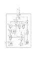
図1は本実施形態の送信装置と受信装置を含むシステムの全体の構成図である。動画データのストリーミング機能を有する送信装置101がネットワークを介して受信装置102〜104に接続している。送信装置101は、動画データを各受信装置に送信する動画ストリーミングサーバである。送信装置101は、動画データとその動画データに対するFECデータをRTPパケットで送信する。各受信装置は、正常に受信した動画パケット、及び、正常に受信したFECパケットを用いて、正常に受信できなかった動画パケットを復元できる。
FIG. 1 is an overall configuration diagram of a system including a transmission apparatus and a reception apparatus according to this embodiment. A transmitting
なお、本形態では、送信装置101が、各受信装置に異なるセッションで、動画データを送信する例について説明する。送信装置101は、各受信装置から、データの受信状況を示す受信状況情報を受信する。また、送信装置101は、各受信装置からの受信状況情報に応じて、動画データの送信レートを制御すると共に、各受信装置に対して、受信状況情報の送信を制御するためのパケット(送信制御パケット)をRTCPパケットで送信する。また、送信装置101は、受信装置から再送要求を受信すると、要求された動画パケットを再送信する。
In this embodiment, an example in which the
受信装置102〜104は共に送信装置101から動画データを受信するクライアントである。また、各受信装置は、動画データの受信状況を示す受信状況情報や、受信できなかった動画パケットの再送信要求を、RTCPパケットで送信装置101に送信する。
The
通信経路105〜109は、実際には、様々な通信路と中継器で構成される。例えば、通信経路108は、無線の通信経路と有線の通信経路の組み合わせで構成される。送信装置101から各受信装置までのネットワーク帯域やパケットロス率はそれぞれ異なる。また、送信装置101から各受信装置までのパケットロス率や利用可能なネットワーク帯域は、それぞれ時間的に変動する。
The
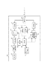
図2は本実施形態の送信装置101の機能構成を示すブロック図である。送信装置101は、動画格納部201、動画符号化部202、パケット生成部203、バッファ204、送信部205、通信インターフェース206を備える。また、送信装置101は、セッション情報格納部207、制御部208、FEC生成部209、パケット再送部210、RTCP生成部211、通信状況解析部212、RTCP解析部213、受信部214を備える。送信装置101は、通信インターフェース206を介して、通信経路105に接続される。動画符号化部202は、制御部208による符号化レートの指示に従い、動画格納部201の動画データを符号化する。パケット生成部203は、動画符号化部202による符号化済みの動画データを、ネットワーク送信する為のパケットデータに変換し、バッファ204に格納する。
FIG. 2 is a block diagram illustrating a functional configuration of the
FEC生成部209は、制御部208によるFECレートの指示に従い、バッファ204に格納された動画パケットからFECパケットを生成し、送信部205に出力する。なお、FECレートは、動画データのパケット数に対するFECパケットのパケット数である。 The FEC generation unit 209 generates an FEC packet from the moving image packet stored in the buffer 204 in accordance with the FEC rate instruction from the control unit 208 and outputs the FEC packet to the transmission unit 205. The FEC rate is the number of FEC packets with respect to the number of moving image data packets.
送信部205は、制御部208からの指示に応じて、セッション情報格納部207に記録されている各受信装置に対して、動画パケット、及び、FECパケットを送信する。
In response to an instruction from the control unit 208, the transmission unit 205 transmits a moving image packet and an FEC packet to each receiving device recorded in the session
受信部214は、動画データの送信先である各受信装置からのRTCPパケットを受信し、RTCP解析部213に出力する。受信部214が受信装置から受信するRTCPパケットには、受信状況情報や、再送要求パケットがある。RTCP解析部213は再送要求パケットを制御部208に出力し、受信状況情報を通信状況解析部212に出力する。
The receiving unit 214 receives the RTCP packet from each receiving device that is the transmission destination of the moving image data, and outputs it to the RTCP analyzing unit 213. The RTCP packet received by the reception unit 214 from the reception device includes reception status information and a retransmission request packet. The RTCP analysis unit 213 outputs a retransmission request packet to the control unit 208 and outputs reception status information to the communication
RTCP解析部213から再送要求パケットを受信した制御部208は、再送信を要求されている動画パケットを送信部205を介して再送信させる。また、RTCP解析部213から受信状況情報を受信した通信状況解析部212は、受信状況情報から通信状況のパラメータを算出し、制御部208に通知する。
The control unit 208 that has received the retransmission request packet from the RTCP analysis unit 213 causes the moving image packet requested to be retransmitted to be retransmitted via the transmission unit 205. In addition, the communication
本形態の受信状況情報には、セッションが開始されてから送信された動画パケットとFECパケット数の合計を示す総パケット数と、受信装置が正常に受信できなかったエラーパケットの総パケット数とが含まれている。通信状況解析部212は、受信状況情報に基づいて、所定期間ごとのエラー率を算出し、制御部208に通知する。
In the reception status information of this embodiment, the total number of packets indicating the total number of moving image packets and FEC packets transmitted since the session was started, and the total number of error packets that could not be received normally by the receiving apparatus. include. The communication
制御部208は、通信状況解析部212から通知されたエラー率に基づいて、受信装置に対する送信レートを決定する。そして、制御部208は、決定した送信レートに基づいて、動画符号化部202に対して動画データの符号化レートを指示すると共に、FEC生成部209に対してFECレートを指示する。また、制御部208は、受信装置による受信状況情報の送信タイミングを決定する。そして、制御部208は、決定された受信状況情報の送信タイミングを受信装置に通知するためのRTCPパケット(送信制御パケット)の生成をRTCP生成部211に依頼し、生成された送信制御パケットを送信部205を介して受信装置に送信させる。
The control unit 208 determines a transmission rate for the receiving device based on the error rate notified from the communication
すなわち、制御部208は、受信部214により受信された受信状況情報に応じて、送信部205からのデータを受信中の受信装置による送信部205からのデータの受信状況を示す受信状況情報の送信を制御する。 That is, the control unit 208 transmits the reception status information indicating the reception status of the data from the transmission unit 205 by the reception device that is receiving the data from the transmission unit 205 according to the reception status information received by the reception unit 214. To control.
図3は、送信装置101が受信装置に送信する送信制御パケットの指示内容の例である。図3(a)は、次回の送信時刻と、その後の送信インターバルを指示するタイプである。すなわち、制御部208は、送信部205を介して、受信状況情報の次回の送信時刻と、その後の送信間隔を指示するRTCPパケットを受信装置へ送信する。この例では、次回の送信時刻(12301500ミリ秒)、及び、それ以後の送信間隔(1500ミリ秒)が指示される。なお、本形態の制御部208は、受信状況情報の送信タイミングを、NTP(Network Time Protocol)のタイムスタンプで指示する。
FIG. 3 is an example of instruction contents of a transmission control packet transmitted from the
図3(b)は、次回の送信時刻を指示せず、送信インターバルのみを指示するタイプである。すなわち、制御部208は、送信部205を介して、受信状況情報の送信間隔を指示するRTCPパケットを受信装置へ送信する。この例では、送信間隔(4000ミリ秒)のみが指示される。 FIG. 3B shows a type in which only the transmission interval is instructed without instructing the next transmission time. That is, the control unit 208 transmits an RTCP packet instructing the transmission interval of the reception status information to the reception device via the transmission unit 205. In this example, only the transmission interval (4000 milliseconds) is indicated.
図3(c)は、次回以降の送信時刻を列挙して指示するタイプである。すなわち、制御部208は、送信部205を介して、複数の受信状況情報の送信時刻を指示するRTCPパケットを受信装置へ送信する。この例では、5つの送信時刻が列挙されている。 FIG. 3C is a type in which the next transmission time and subsequent times are listed and instructed. That is, the control unit 208 transmits an RTCP packet instructing transmission times of a plurality of reception status information to the reception device via the transmission unit 205. In this example, five transmission times are listed.
図3(d)は、受信状況情報の送信時刻を受信装置に決定させるタイプである。すなわち、制御部208は、送信部205を介して、受信状況情報の送信タイミングを受信装置に決定させることを指示するRTCPパケットを受信装置へ送信する。 FIG. 3D illustrates a type in which the reception apparatus determines the transmission time of the reception status information. That is, the control unit 208 transmits, via the transmission unit 205, an RTCP packet that instructs the reception device to determine the transmission timing of the reception status information.
図4は本実施形態の受信装置102〜104の機能構成を示すブロック図である。受信装置は、受信部401、バッファ402、パケット結合部403、動画復号部404、表示部405、エラー測定部406、RTCP解析部407、FEC復号部408を備える。また、受信装置は、制御部409、セッション情報格納部410、再送要求部411、通信品質報告部412、送信部413、通信インターフェイス414を備える。受信装置は、通信インターフェイス414を介して、通信経路に接続される。
FIG. 4 is a block diagram illustrating a functional configuration of the receiving
受信部401は、通信インターフェイス414を介して受信した動画パケット及びFECパケットをバッファ402に保存する。また、受信部401は、受信したRTCPパケットをRTCP解析部407に出力する。本形態で受信されるRTCPパケットには、送信制御パケット(受信状況情報の送信を制御するためのパケット)や、ほかの受信装置によって送信された再送要求パケットがある。また、受信部401は受信した動画パケットのシーケンスナンバーをエラー測定部406に通知する。
The receiving unit 401 stores the moving image packet and the FEC packet received via the communication interface 414 in the
パケット結合部403は、バッファ402に保存された1つ以上の動画パケットの動画データを結合し、動画復号部404に出力する。動画復号部404は、結合された動画データを復号して表示部405に出力する。表示部405は、復号された動画データを表示する。
The packet combining unit 403 combines the moving image data of one or more moving image packets stored in the
エラー測定部406は、受信部401から通知されたシーケンスナンバーからエラーパケットのシーケンスナンバーを特定し、制御部409に通知する。 The error measurement unit 406 identifies the sequence number of the error packet from the sequence number notified from the reception unit 401 and notifies the control unit 409 of the error packet sequence number.
制御部409は、エラー測定部406からの通知に応じて、エラーパケットが発生したことを通信品質報告部412に通知する。また、制御部409は、エラーパケットを、正常に受信された動画パケットとFECパケットを用いて復元可能であるか否かを判定し、復元可能であると判定されたエラーパケットの復元を、FEC復号部に依頼する。また、制御部409は、復元可能でないと判定されたエラーパケットのシーケンスナンバーを再送要求部411に通知する。 In response to the notification from the error measurement unit 406, the control unit 409 notifies the communication quality report unit 412 that an error packet has occurred. In addition, the control unit 409 determines whether or not the error packet can be restored using the normally received moving image packet and the FEC packet, and restores the error packet that is judged to be restored. Ask the decryption unit. In addition, the control unit 409 notifies the retransmission request unit 411 of the sequence number of the error packet that is determined not to be recoverable.
ただし、制御部409は、復元可能でないと判定されたエラーパケットと同じパケットの再送要求パケットを、他の受信装置から受信した場合、当該エラーパケットのシーケンスナンバーを再送要求部411に通知しない。これにより、同じエラーパケットの再送要求パケットが重複して送られないようにすることができる。なお、本形態では、各受信装置はそれぞれ異なる動画データを受信しているので、復元可能でないと判定されたエラーパケットは、すべて再送要求される。 However, the control unit 409 does not notify the retransmission request unit 411 of the sequence number of the error packet when the retransmission request packet of the same packet as the error packet determined to be unrecoverable is received from another receiving apparatus. As a result, it is possible to prevent the retransmission request packets of the same error packet from being duplicated. In this embodiment, since each receiving device receives different moving image data, all error packets determined to be unrecoverable are requested to be retransmitted.
FEC復号部408は、制御部409に復元を依頼されたエラーパケットの復元に必要となる動画パケット及びFECパケットをバッファ402から検索し、復元する。
The FEC decoding unit 408 searches the
再送要求部411は、制御部409から通知されたシーケンスナンバーに基づいて、エラーパケットの再送信を依頼するRTCPパケットを作成し、送信部413を介して送信装置101に送信する。
The retransmission request unit 411 creates an RTCP packet that requests retransmission of an error packet based on the sequence number notified from the control unit 409, and transmits the RTCP packet to the
RTCP解析部407は、受信したRTCPパケットを解析し、解析結果を制御部409に通知する。本形態のRTCP解析部407は、送信制御パケットを解析し、図3のいずれのタイプであるかを判定する。そして、RTCP解析部407は、送信制御パケットのタイプに応じた受信状況情報の送信タイミングを、制御部409に通知する。
The
RTCP解析部407からの通知を受けた制御部409は、受信状況情報の送信タイミングを、セッション情報格納部410に記録する。
Upon receiving the notification from the
図5は、セッション情報格納部410に格納される、受信状況情報の送信タイミングを管理するための管理テーブルの例である。図5に示すように、管理テーブルは、受信セッション番号501と前回送信時刻502と送信タイミング指定形式503と送信タイミング指定値504で構成される。本形態の受信装置は、受信状況情報の送信タイミングを、セッションごとに管理している。例えば、受信装置102は、送信装置101から、セッション番号1のセッションに基づいて第1の動画データを受信すると共に、送信装置101とは別の送信装置から、セッション番号2のセッションに基づいて第2の動画データを受信している。
FIG. 5 is an example of a management table for managing the transmission timing of reception status information stored in the session information storage unit 410. As shown in FIG. 5, the management table includes a reception session number 501, a
つまり、図5に示す管理テーブルを格納している受信装置102は、12302800ミリ秒に達したことに応じて、送信装置101に対して受信状況情報を送信し、その後、2500ミリ秒間隔で受信状況情報を送信する。また、受信装置102は、別の送信装置に対して、12301300ミリ秒に達したことに応じて受信状況情報を送信し、その後、12302100に達したことに応じて、次の受信状況情報を送信する。
That is, the receiving
制御部409は、RTCP解析部407からの通知に応じて、セッション情報格納部410に格納される設定値を変更する。
The control unit 409 changes the setting value stored in the session information storage unit 410 in response to the notification from the
次に、図6を用いて、受信装置102〜104へ動画データを送信する送信装置101の処理について説明する。なお、図6のフローチャートの処理は、CPUがROMに格納されているプログラムを実行することにより、実現される。
Next, processing of the
ステップS601(受信手順)において、受信部214が受信状況情報を受信装置から受信したことに応じて、通信状況解析部212は、受信状況情報の解析結果を制御部208に通知する。
In step S601 (reception procedure), in response to the reception unit 214 receiving the reception status information from the reception device, the communication
ステップS602において、制御部208は、複数の受信装置からの受信状況情報の解析結果に基づいて、複数の受信装置の受信状況が対応しているか否かを判定する。例えば、制御部208は、受信装置102から第1の受信状況情報を受信してから所定時間内に、受信装置103から第2の受信状況情報を受信した場合、第1、第2の受信状況情報が示す受信状況(例えばエラー率)が対応しているか判定する。さらに制御部208は、第2の受信状況情報の受信後に受信装置102から受信した第3の受信状況情報が示す受信状況と、第3の受信状況情報を受信してから所定時間内に受信装置103から受信した第4の受信状況情報が示す受信状況が対応しているか判定する。そして、制御部208は、第1、第2の受信状況情報が示す受信状況が対応し、且つ、第3、第4の受信状況情報が示す受信状況が対応すると判定される場合、受信装置102、103の受信状況が対応すると判定する。
In step S602, the control unit 208 determines whether or not the reception statuses of the plurality of reception devices are compatible based on the analysis result of the reception status information from the plurality of reception devices. For example, when the control unit 208 receives the second reception status information from the
ステップS602において、複数の受信装置の受信状況が対応していると判定された場合はステップS604に進み、対応していないと判定された場合はステップS603に進む。 In step S602, if it is determined that the reception statuses of the plurality of receiving apparatuses are compatible, the process proceeds to step S604, and if it is determined that they are not compatible, the process proceeds to step S603.
なお、送信装置101が1つの受信装置にのみデータを送信している場合は、ステップS603に進む。
If the transmitting
ステップS603(レート制御手順)において、制御部208は、ステップS601で受信した受信状況情報の解析結果に応じて、受信装置に対する送信レートを決定する。例えば、制御部208は、エラー率が所定のエラー率よりも高い場合は送信レートを下げ、エラーが発生していない場合で、かつ、送信レートが目標レートに達していない場合は送信レートを上げる。 In step S603 (rate control procedure), the control unit 208 determines a transmission rate for the receiving apparatus according to the analysis result of the reception status information received in step S601. For example, the control unit 208 decreases the transmission rate when the error rate is higher than a predetermined error rate, and increases the transmission rate when no error occurs and the transmission rate does not reach the target rate. .
ステップS614(送信制御手順)において、制御部208は、ステップS601で受信した受信状況情報の解析結果に応じて、受信状況情報の送信を制御するためのパケット(送信制御パケット)をRTCP生成部211に生成させる。そして、制御部208は、生成された送信制御パケットを送信部205を介して受信装置へ送信させる。 In step S614 (transmission control procedure), the control unit 208 generates a packet (transmission control packet) for controlling transmission of reception status information in accordance with the analysis result of the reception status information received in step S601. To generate. Then, the control unit 208 causes the generated transmission control packet to be transmitted to the reception device via the transmission unit 205.
本形態の制御部208は、エラー率が所定のエラー率よりも高い場合、送信レートを下げると共に、受信装置が、所定のエラー率よりも低かった場合よりも早いタイミング、かつ、短い間隔で受信状況情報を送信するように制御する。すなわち、制御部208は、受信状況情報が第1の受信状況(第1のエラー率)を示している場合、受信状況情報が第2の受信状況(第2のエラー率)を示している場合よりも早いタイミングで次の受信状況情報を送信させる。また、制御部208は、受信状況情報が第1の受信状況を示している場合は第1の期間の受信状況を示す受信状況情報を送信させ、受信状況情報が第2の受信状況を示している場合は第1の期間よりも短い第2の期間の受信状況を示す受信状況情報を送信させる。なお、第2の受信状況のエラー率(第2のエラー率)は、第1の受信状況のエラー率(第1のエラー率)よりも、エラーしたデータが少ない。 When the error rate is higher than the predetermined error rate, the control unit 208 according to the present embodiment reduces the transmission rate, and receives the reception device at a timing earlier than that when the receiving device is lower than the predetermined error rate, and at a short interval. Control to send status information. That is, when the reception status information indicates the first reception status (first error rate), the control unit 208 indicates that the reception status information indicates the second reception status (second error rate). The next reception status information is transmitted at an earlier timing. In addition, when the reception status information indicates the first reception status, the control unit 208 transmits reception status information indicating the reception status of the first period, and the reception status information indicates the second reception status. If there is, the reception status information indicating the reception status of the second period shorter than the first period is transmitted. Note that the error rate in the second reception situation (second error rate) is less in error data than the error rate in the first reception situation (first error rate).
また、制御部208は、エラー率が所定のエラー率よりも低く、かつ、送信レートが目標レートに達していない場合、送信レートを上げると共に、受信装置が、制御をしない場合よりも早いタイミングで次の受信状況情報を送信するように制御する。すなわち、制御部208は、受信状況情報が示すエラー情報に基づいて送信レートを上げた場合、送信レートを上げない場合よりも受信装置が早いタイミングで次の受信状況情報を送信するように制御する。受信状況情報が早いタイミングで送信されることにより、送信装置101は、通信状況をより早く知ることができる。
Further, the control unit 208 increases the transmission rate when the error rate is lower than the predetermined error rate and the transmission rate does not reach the target rate, and at a timing earlier than when the receiving apparatus does not perform control. Control to transmit the next reception status information. That is, the control unit 208 performs control so that when the transmission rate is increased based on the error information indicated by the reception status information, the reception apparatus transmits the next reception status information at an earlier timing than when the transmission rate is not increased. . By transmitting the reception status information at an early timing, the
また、制御部208は、エラー率が所定のエラー率よりも低く、かつ、送信レートが目標レートに達している場合、送信レートを変更しないと共に、受信装置が、制御をしない場合よりも遅いタイミングで次の受信状況情報が送信されるように制御する。また、この場合、制御部208は、次回以降の受信状況情報の送信間隔が長くなるように制御する。受信状況情報の送信回数を少なくすることにより、受信状況情報の送受信にかかる負荷やネットワークの負荷を低減できる。 In addition, when the error rate is lower than the predetermined error rate and the transmission rate has reached the target rate, the control unit 208 does not change the transmission rate, and at a later timing than when the receiving apparatus does not perform control. To control so that the next reception status information is transmitted. Further, in this case, the control unit 208 performs control so that the transmission interval of the reception status information after the next time becomes longer. By reducing the number of times of reception status information transmission, it is possible to reduce the load on the transmission and reception of the reception status information and the load on the network.
ステップS602で、受信装置102、103の受信状況が対応していると判定された場合、ステップS604において、制御部208は、受信装置102、103に対して、一致する期間の受信状況を示す受信状況情報を送信させる。例えば、制御部208は、次回送信時刻12303500ミリ秒、インターバル1000ミリ秒を指定した送信制御パケットをRTCP生成部211に生成させ、それを受信装置102、103のそれぞれへ送信させる。これにより、受信装置102、103は、それぞれ同じタイミングで受信状況情報を送信するようになる。
If it is determined in step S602 that the reception statuses of the
すなわち、制御部208は、第1の受信状況情報を送信した受信装置102と、第1の受信状況情報に受信状況が対応する第2の受信状況情報を送信した受信装置103とに、一致するタイミングで受信状況情報を送信させる。第2の受信状況情報は、第1の受信状況情報を受信してから、所定時間内に送信装置101によって受信された受信状況情報である。
That is, the control unit 208 matches the receiving
また、ステップS604において、制御部208は、受信装置102、103に一致する期間の受信状況情報を送信させる前よりも、受信状況情報の送信間隔を短くさせる。このようにすることで、受信装置102、103の受信状況の比較を、より精度良く行うことができる。
In step S604, the control unit 208 shortens the reception status information transmission interval before transmitting the reception status information in the period matching the
なお、本形態では、ステップS602で受信状況が対応していると判定された場合に、一致する期間の受信状況情報を送信させる例について説明したが、ステップS602の判定をすることなく、一致する期間の受信状況情報を送信させることも可能である。 In this embodiment, the example in which the reception status information in the matching period is transmitted when it is determined in step S602 that the reception status is compatible has been described. However, the reception status information matches without performing the determination in step S602. It is also possible to transmit period reception status information.
ステップS605において、制御部208は、複数の受信装置102、103から、一致する期間の受信状況情報を受信する。
In step S <b> 605, the control unit 208 receives reception status information for a matching period from the plurality of
ステップS606において、制御部208は、ステップS605で受信された受信状況情報に基づいて、複数の受信装置102、103がボトルネックを共有しているか否かを判定する。すなわち、制御部208は、複数の受信装置102、103のそれぞれから、一致する期間の受信状況情報を、複数個、受信し、それらのエラー率の変動が対応しているか否かを判定する。例えば、受信装置102、103からの受信状況情報により、受信装置102、103の第1の期間のエラー率が5%、第2の期間のエラー率が7%、第3の期間のエラー率が10%で一致する場合、ボトルネックを共有していると判定される。また、例えば、第1、第2の期間のエラー率が一致し、第3の期間のエラー率は1%の差異があった場合も、受信装置102、103がボトルネックを共有していると判定される。
In step S606, the control unit 208 determines whether or not the plurality of receiving
ステップS606で、複数の受信装置102、103がボトルネックを共有していると判定された場合はステップS609に進み、ボトルネックを共有していないと判定された場合はステップS607に進む。
If it is determined in step S606 that the plurality of receiving
ステップS607において、制御部208は、ステップS603と同様に、各受信装置から受信した受信状況情報の解析結果に基づいて、データの送信レートを制御する。すなわち、制御部208は、受信装置102からの受信状況情報に基づいて受信装置102へのデータの送信レートを制御し、受信装置103からの受信状況情報に基づいて受信装置103へのデータの送信レートを制御する。そして、ステップS608において、制御部208は、受信装置102、103にそれぞれ異なるタイミングで受信状況情報を送信させると共に、受信状況情報の送信間隔を長くさせる。このように、ボトルネックを共有しないと判定された受信装置からの受信状況情報を、異なるタイミングで送信させることにより、複数の受信装置から同時に受信状況情報を受信するよりも、送信レートの制御やネットワークの負荷を時間的に平準化できる。
In step S607, similarly to step S603, the control unit 208 controls the data transmission rate based on the analysis result of the reception status information received from each receiving apparatus. That is, the control unit 208 controls the transmission rate of data to the receiving
ステップS609において、制御部208は、受信装置102、103に受信状況情報を交互に送信させる。すなわち、制御部208は、受信装置102、103に一致するタイミングで送信させた受信状況情報が対応する場合、受信装置102、103に、受信状況情報を交互に送信させる。
In step S609, the control unit 208 causes the
例えば、制御部208は、次回送信時刻12308500ミリ秒、インターバル2000ミリ秒を指定した第1の送信制御パケットをRTCP生成部211に生成させ、それを受信装置102に送信させる。また、制御部208は、例えば、次回送信時刻12309500ミリ秒、インターバル2000ミリ秒を指定した第2の送信制御パケットをRTCP生成部に生成させ、それを受信装置103に送信させる。なお、制御部208は、ステップS604で、受信装置102、103に、それぞれ1000ミリ秒間隔で受信状況情報を送信させている。
For example, the control unit 208 causes the RTCP generation unit 211 to generate the first transmission control packet specifying the next transmission time 12308500 milliseconds and the interval 2000 milliseconds, and causes the
送信装置101から第1の送信制御パケットを受信した受信装置102は、時刻12308500、12310500、12312500・・・に、送信装置101に対して受信状況情報を送信する。また、送信装置101から第2の送信制御パケットを受信した受信装置103は、時刻12309500、12311500、12313500・・・に、送信装置101に対して受信状況情報を送信する。
The receiving
すなわち、制御部208は、受信装置102、103に受信状況情報を交互に送信させる前よりも、受信装置102による受信状況情報の送信間隔と、受信装置103による受信状況情報の送信間隔とを、それぞれ長くさせる。
That is, the control unit 208 sets the transmission interval of the reception status information by the
このように、送信装置101は、受信装置102、103に受信状況情報を交互に送信させると共に、送信間隔を長くする。このようにすることで、受信状況情報の送受信の負荷やネットワークの負荷を低減しつつ、送信装置101は、ボトルネックの通信状況を短い間隔で(1000ミリ秒ごとに)確認できる。
As described above, the
ステップS610において、制御部208は、受信装置102、103から交互に送信されてくる受信状況情報に基づいて、受信装置102、103へのデータの送信レートをまとめて制御する。例えば、制御部208は、ボトルネックを共有していると判定された受信装置102、103のそれぞれに設定された優先度を取得する。そして、制御部208は、受信装置102、103の受信状況に応じて、送信レートの合計値を決定し、さらに、受信装置102、103の優先度に応じて、受信装置102への第1の送信レートと、受信装置103への第2の送信レートをそれぞれ決定する。これにより、ボトルネックを共有している受信装置102、103のうち、受信装置103よりも優先度が高い受信装置102への送信レートが、受信装置103よりも高く決定される。
In step S610, the control unit 208 collectively controls the data transmission rates to the receiving
ステップS612において、制御部208は、受信装置102、103から交互に送信されてくる受信状況情報に基づいて、受信装置102、103がボトルネックを共有しているか否かを判定する。すなわち、通信状況解析部212が各受信装置からの受信状況情報に基づいて、エラー率の変動を算出し、制御部208に通知する。そして、制御部208は、通信状況解析部212による算出結果に基づいて、受信装置102、103がボトルネックを共有しているか否かを判定する。この判定は、ステップS606と同様に行う。
In step S612, the control unit 208 determines whether or not the receiving
ステップS612において、受信装置102、103がボトルネックを共有していると判定された場合はステップS610に戻り、制御部208は、受信装置102、103の送信レートをまとめて制御する。一方、受信装置102、103がボトルネックを共有していないと判定された場合はステップS613に進み、制御部208は、受信装置102、103に異なるタイミングで受信状況情報を送信させる。
If it is determined in step S612 that the receiving
このように、ボトルネックを共有していない受信装置に異なるタイミングで受信状況情報を送信させることにより、受信状況情報によるネットワークの負荷や、受信状況情報に応じた送信レート制御などの負荷を時間的に平準化することができる。 In this way, by causing reception devices that do not share a bottleneck to transmit reception status information at different timings, the load on the network due to the reception status information and the load such as transmission rate control according to the reception status information are temporally reduced. Can be leveled.
次に、図7のフローチャートを用いて受信装置102〜104の制御部409が受信状況情報の送信タイミングを決定する処理について説明する。
Next, processing in which the control unit 409 of the receiving
ステップS701(受信手順)において、RTCP解析部407は、送信装置101からRTCPパケットを受信する。そして、RTCP解析部407は、RTCPパケットが送信制御パケットであった場合、受信状況情報の送信タイミングを制御するための制御信号を取得して制御部409に通知する。なお、ステップS701でRTCP解析部407が送信制御パケットを受信するということは、それ以前に、少なくとも1つ以上の受信状況情報が送信装置101に送信されている(送信手順)。
In step S <b> 701 (reception procedure), the
ステップ702において、制御部409は、ステップS701でRTCP解析部407から通知された情報が、受信状況情報の送信タイミングを制御するための制御信号であるか否かを判定する。ステップS701で通知された情報が受信状況情報の送信タイミングを制御するための制御信号であると判定された場合、ステップS703に進み、受信状況情報の送信タイミングを制御するための制御信号でないと判定された場合、ステップS704に進む。
In step 702, the control unit 409 determines whether the information notified from the
ステップS703(制御手順)において、制御部409は、ステップS701で通知された制御信号に基づいて、受信状況情報の送信タイミングの設定を変更する。制御部409は、図3(a)に示すような内容を含む制御信号を受けると、次回送信時刻を指定された値に設定すると共に、受信状況情報の送信インターバルを設定する。つまり、制御部409は、通知された制御信号に基づいて、図5に示したような、セッション情報格納部410に格納されている情報を書き換える。 In step S703 (control procedure), the control unit 409 changes the transmission timing setting of the reception status information based on the control signal notified in step S701. When the control unit 409 receives the control signal including the contents as shown in FIG. 3A, the control unit 409 sets the next transmission time to the specified value and sets the transmission interval of the reception status information. That is, the control unit 409 rewrites information stored in the session information storage unit 410 as illustrated in FIG. 5 based on the notified control signal.
すなわち、制御部409は、受信状況情報が送信された後に受信された制御信号に応じて、制御信号の受信後に受信したデータの受信状況を示す受信状況情報の送信を制御する。 That is, the control unit 409 controls the transmission of reception status information indicating the reception status of data received after receiving the control signal, in accordance with the control signal received after the reception status information is transmitted.
ステップS407において、制御部409は、受信したRTCPパケットに基づく処理のうち、受信状況情報の送信タイミング以外の処理を行う。例えば、RTCPパケットとして再送要求パケットを受信した場合、制御部409は、ステップS407でパケットの再送処理を行う。 In step S407, the control unit 409 performs processing other than the transmission timing of the reception status information among the processing based on the received RTCP packet. For example, when a retransmission request packet is received as an RTCP packet, the control unit 409 performs packet retransmission processing in step S407.
<実施形態2>
次に第2の実施形態について、実施形態1との差異を中心に説明する。本実施形態では、受信装置102〜104に対して、同じ動画データをマルチキャスト送信する送信装置101が、受信装置に対して再送信要求の送信タイミングを指示する例について説明する。
<
Next, a second embodiment will be described focusing on differences from the first embodiment. In the present embodiment, an example will be described in which the
本実施形態の送信装置101と受信装置102〜104の構成は、実施形態1と同様である。更に、本実施形態の制御部208は、RTCP生成部211に対して、再送要求制御パケットの作成を依頼する。また、制御部208は、RTCP生成部211により生成された再送要求制御パケットを、送信部205を介して受信装置に送信させる。
The configurations of the
再送要求制御パケットは、受信装置に対して再送要求を送信可能なタイミングを指定するためのパケットである。受信装置は、動画データのパケットロスがあった場合、再送要求制御パケットで指定されたタイミングまで再送要求の送信を待つ。 The retransmission request control packet is a packet for designating a timing at which a retransmission request can be transmitted to the receiving apparatus. When there is a packet loss of moving image data, the receiving apparatus waits for a retransmission request until the timing specified by the retransmission request control packet.
本形態の制御部208が再送要求の送信タイミングの指定方法として、例えば、インターバル型、時間列挙型、待ち時間指定型がある。インターバル型では、次回送信時刻(例えば12300010ミリ秒)とインターバル(例えば33ミリ秒)が指定される。また、時間列挙型では、列挙数(例えば5)、送信時刻(12301010ミリ秒、12301043ミリ秒、12301076ミリ秒、12301109ミリ秒、12301132ミリ秒)が指定される。また、待ち時間指定型では、待ち時間(例えば10ミリ秒)が指定される。待ち時間指定型の再送制御パケットを受信した受信装置は、動画データのパケットロスを検知してから10ミリ秒待って、再送要求パケットを送信装置101に送信する。なお、受信装置は、10ミリ秒の待ち時間中に、ロスしたパケットの再送要求パケットを他の受信装置から受信した場合、再送要求パケットを送信しない。また、本形態では、再送要求の送信タイミングをNTPのタイムスタンプで指示する例について説明しているが、ほかの指示方法を用いても良い。
For example, the control unit 208 of the present embodiment has a method for specifying the transmission timing of a retransmission request, such as an interval type, a time enumeration type, and a waiting time specification type. In the interval type, a next transmission time (for example, 12300010 milliseconds) and an interval (for example, 33 milliseconds) are designated. In the time enumeration type, the number of enumerations (for example, 5) and the transmission time (12301010 milliseconds, 12301043 milliseconds, 12301076 milliseconds, 12301109 milliseconds, 12301132 milliseconds) are specified. In the waiting time designation type, a waiting time (for example, 10 milliseconds) is designated. The receiving device that has received the waiting time designation type retransmission control packet waits for 10 milliseconds after detecting the packet loss of the moving image data, and transmits the retransmission request packet to the transmitting
次に、図8を用いて、本実施形態の制御部208が、受信装置による再送要求の送信タイミングを制御する処理を説明する。 Next, a process in which the control unit 208 according to the present embodiment controls the transmission timing of the retransmission request by the receiving apparatus will be described with reference to FIG.
ステップS801において、制御部208は、各受信装置102〜104からの受信状況情報に基づいて通信状況解析部212によって算出された解析結果(例えば所定期間ごとのエラー率)を受信する。
In step S801, the control unit 208 receives an analysis result (for example, an error rate for each predetermined period) calculated by the communication
ステップS802において、制御部208は、ステップS801で受信した解析結果に基づいて、各受信装置がボトルネックを共有しているか否かを判定する。ステップS801、S802の処理は、図6のステップS601〜S606の処理に対応する。ステップS802で受信装置がボトルネックを共有していると判定された場合はステップS803に進み、ボトルネックを共有していないと判定された場合は本形態の処理を終了する。この説明では、送信装置101によるマルチキャストでの動画データの送信先である受信装置102〜104のうち、受信装置102、103がボトルネックを共有していると判定されたとする。
In step S802, the control unit 208 determines whether each receiving apparatus shares a bottleneck based on the analysis result received in step S801. The processes in steps S801 and S802 correspond to the processes in steps S601 to S606 in FIG. If it is determined in step S802 that the receiving apparatus shares the bottleneck, the process proceeds to step S803. If it is determined that the receiving apparatus does not share the bottleneck, the process of this embodiment is terminated. In this description, it is assumed that the receiving
ステップS803において、制御部208は、ボトルネックを共有していると判定された受信装置102、103による再送要求の送信タイミング決定する。例えば、制御部208は、インターバル型で制御する場合、ボトルネックを共有している複数の受信装置のうち、より処理能力の高い受信装置のインターバルの値を小さく、処理能力の低い受信装置のインターバルの値を大きく設定する。これにより、処理能力の高い受信装置にできるだけ多くの再送要求を送信させることができる。
In step S803, the control unit 208 determines the transmission timing of the retransmission request by the receiving
ただし、このようなインターバルの決定方法に限らず、例えば、マルチキャストグループに加入した順序に基づいて、インターバルを決定するようにしても良い。また、例えば、各受信装置の優先度や、ユーザによる指定に基づいて、インターバルを決定するようにしても良い。 However, the interval determination method is not limited to this, and for example, the interval may be determined based on the order of joining the multicast group. Further, for example, the interval may be determined based on the priority of each receiving device or the designation by the user.
ステップS804において、制御部208は、ボトルネックを共有する受信装置に、ステップS803で決定された送信タイミングで再送要求を送信させるための再送要求制御パケットの生成を、RTCP生成部211に依頼する。そして、制御部208は、RTCP生成部211で生成された再送要求制御パケットを、ボトルネックを共有する受信装置へ送信させる。すなわち、制御部208は、同じデータの送信先であって、受信状況情報が対応する受信装置102、103に対し、エラーしたデータの再送要求を送信可能なタイミングを指定する。
In step S804, the control unit 208 requests the RTCP generation unit 211 to generate a retransmission request control packet for causing a receiving apparatus sharing a bottleneck to transmit a retransmission request at the transmission timing determined in step S803. Then, the control unit 208 causes the retransmission request control packet generated by the RTCP generation unit 211 to be transmitted to a receiving apparatus sharing a bottleneck. That is, the control unit 208 designates a timing at which a retransmission request for error data can be transmitted to the receiving
制御部208は、例えば、インターバル型で制御する場合、次回送信時刻12301000ミリ秒、インターバル33ミリ秒を指定する第1の再送要求制御パケットの生成をRTCP生成部211に依頼する。また、制御部208は、次回送信時刻12301015ミリ秒、インターバル33ミリ秒を指定した第2の再送要求制御パケットの生成をRTCP生成部211に依頼する。そして、制御部208は、第1の再送要求制御パケットを受信装置102へ送信させ、第2の再送要求制御パケットを受信装置103へ送信させる。
For example, when controlling by the interval type, the control unit 208 requests the RTCP generation unit 211 to generate a first retransmission request control packet designating the next transmission time 12301000 milliseconds and the interval 33 milliseconds. In addition, the control unit 208 requests the RTCP generation unit 211 to generate a second retransmission request control packet specifying the next transmission time 12301015 milliseconds and an interval of 33 milliseconds. Then, the control unit 208 causes the
また、制御部208は、例えば、待ち時間指定型で制御する場合、待ち時間を5ミリ秒とする第1の再送要求制御パケットと、待ち時間を20ミリ秒とする第2の再送要求制御パケットの生成をRTCP生成部211に依頼する。そして、制御部208は、第1の再送要求制御パケットを受信装置102へ送信させ、第2の再送要求制御パケットを受信装置103へ送信させる。また、制御部208は、受信装置による再送要求の送信タイミングを、時間列挙型で制御することも可能である。
In addition, for example, when the control unit 208 performs control with a waiting time designation type, the first retransmission request control packet with a waiting time of 5 milliseconds and the second retransmission request control packet with a waiting time of 20 milliseconds. Is requested to the RTCP generation unit 211. Then, the control unit 208 causes the
本形態の受信装置が送信する再送要求パケットの宛先には、マルチキャストアドレスが付加される。従って、例えば受信装置102が第1の動画パケットの再送要求パケットを送信すると、当該再送要求パケットは送信装置101だけでなく、受信装置103、104でも受信される。そして、受信装置103、104は、第1の動画パケットの再送要求パケットを受信すると、たとえ第1の動画パケットを正常に受信していなかったとしても、再送要求を送信しない。このようにすることで、同じ動画パケットの再送要求が、複数の受信装置から重複して送信されないようになる。
A multicast address is added to the destination of the retransmission request packet transmitted by the receiving apparatus of this embodiment. Therefore, for example, when the receiving
次に、図9を用いて、受信装置による再送要求の送信タイミングを制御する処理について説明する。 Next, processing for controlling the transmission timing of the retransmission request by the receiving apparatus will be described with reference to FIG.
ステップS901において、RTCP解析部407は、送信装置101からRTCPパケットを受信する。そして、RTCP解析部407は、RTCPパケットが再送要求制御パケットであった場合、再送要求の送信タイミングを制御するための制御信号を取得して制御部409に通知する。
In step S <b> 901, the
ステップS902において、制御部409は、ステップS901でRTCP解析部407から通知された情報が、再送要求の送信タイミングを制御するための制御信号であるか否かを判定する。そして、制御部409は、再送要求の送信タイミングを制御するための制御信号であると判定された場合はステップS903に進み、再送要求の送信タイミングを制御するための制御信号でないと判定された場合はステップS904に進む。
In step S902, the control unit 409 determines whether the information notified from the
ステップS903において、制御部409は、ステップS901で通知された制御信号に基づいて、再送要求の送信タイミングの設定を変更する。制御部409は、例えば、インターバル型の制御信号を受けると、次回送信時刻を指定された値に設定すると共に、再送要求の送信インターバルを設定する。つまり、制御部409は、通知された制御信号に基づいて、セッション情報格納部410に格納されている再送要求の送信タイミングに関する情報を書き換える。 In step S903, the control unit 409 changes the setting of the retransmission request transmission timing based on the control signal notified in step S901. For example, when receiving an interval type control signal, the control unit 409 sets the next transmission time to a specified value and sets the transmission interval of the retransmission request. That is, the control unit 409 rewrites the information regarding the transmission timing of the retransmission request stored in the session information storage unit 410 based on the notified control signal.
図10に、本形態のセッション情報格納部410に格納される、再送要求の送信タイミングを管理するための管理テーブルの例である。図10に示すように、管理テーブルは、セッション番号1001、タイミング指定方式1002、タイミング指定値1003で構成される。本形態の受信装置は、再送要求の送信タイミングを、セッションごとに管理している。例えば、受信装置102は、送信装置101から、セッション番号1のセッションに基づいて、マルチキャストによる動画データを受信している。また、受信装置102は、送信装置101とは異なる送信装置から、セッション番号2のセッションに基づいて、動画データを受信している。
FIG. 10 is an example of a management table for managing the transmission timing of the retransmission request stored in the session information storage unit 410 of the present embodiment. As shown in FIG. 10, the management table includes a session number 1001, a timing designation method 1002, and a timing designation value 1003. The receiving apparatus of this embodiment manages the transmission timing of the retransmission request for each session. For example, the receiving
次に、図11を用いて、本形態の受信装置の処理について説明する。図11の処理は、制御部409が、動画データのパケットロスを検知したことによって開始される。 Next, processing of the receiving apparatus of this embodiment will be described using FIG. The processing in FIG. 11 is started when the control unit 409 detects a packet loss of moving image data.
ステップS1101において、制御部409は、再送要求の送信可否を判定するための再送要求時間情報を、セッション情報格納部410から取得する。タイミング指定方式がインターバル型の場合、制御部409は、図10に示したタイミング指定値のうち、次回送信時刻を、再送要求時間情報として、セッション情報格納部410から取得する。なお、次回送信時刻は、ある時刻であっても、幅を持った期間であっても良い。また、タイミング指定方式が待ち時間指定型の場合、制御部409は、待ち時間のカウント値を、再送要求時間情報として、セッション情報格納部410から取得する。 In step S1101, the control unit 409 acquires retransmission request time information for determining whether or not a retransmission request can be transmitted from the session information storage unit 410. When the timing designation method is an interval type, the control unit 409 acquires the next transmission time from the session information storage unit 410 as retransmission request time information among the timing designation values shown in FIG. It should be noted that the next transmission time may be a certain time or a wide period. When the timing designation method is the wait time designation type, the control unit 409 acquires the wait time count value from the session information storage unit 410 as retransmission request time information.
ステップS1102において、制御部409は、ステップS1101で取得された再送要求時間情報に基づいて、現在、再送要求を送信可能であるか否かを判定する。例えば、インターバル型の場合、制御部409は、現在時刻が、次回送信時刻に達したと判定された場合、再送要求を送信可能であると判定する。また、待ち時間指定型の場合、制御部409は、待ち時間のカウント値が、設定された待ち時間に達したと判定された場合、再送要求を送信可能であると判定する。再送要求を送信可能であると判定された場合はステップS1103に進み、制御部409は、再送要求を送信装置101へ送信させる。一方、ステップS1102において再送要求を送信可能でないと判定された場合はステップS1104に進み、制御部409は、再送要求の送信待ちをすると共に、他の受信装置から再送要求を受信したか否かを判定する。
In step S1102, the control unit 409 determines whether a retransmission request can be transmitted at present based on the retransmission request time information acquired in step S1101. For example, in the case of the interval type, the control unit 409 determines that a retransmission request can be transmitted when it is determined that the current time has reached the next transmission time. In the case of the waiting time designation type, the control unit 409 determines that a retransmission request can be transmitted when it is determined that the waiting time count value has reached the set waiting time. If it is determined that the retransmission request can be transmitted, the process proceeds to step S1103, and the control unit 409 causes the
ステップS1104で、他の受信装置から再送要求を受信したと判定された場合はステップS1105に進み、制御部409は、受信した再送要求に対応する動画データの再送要求の送信を取り消す。 If it is determined in step S1104 that a retransmission request has been received from another receiving apparatus, the process advances to step S1105, and the control unit 409 cancels the transmission of the moving image data retransmission request corresponding to the received retransmission request.
例えば、受信装置102の制御部409は、同じ動画データをマルチキャストで受信中の受信装置103から、第1のパケットの再送要求を受信したことに応じて、ステップS1105で、第1のパケットの再送要求の送信を取り消す。
For example, the control unit 409 of the receiving
このように、本実施形態の送信装置101は、マルチキャストによる同じ動画データの送信先である受信装置102、103、104のうち、ボトルネックを共有している受信装置102、103による再送要求の送信タイミングが一致しないように制御する。このようにすることで、複数の受信装置から、同じ動画パケットの再送要求が重複して送信される可能性を低減できる。また、マルチキャストの送信先であるすべての受信装置102、103、104による再送要求の送信タイミングが一致しないように制御されるよりも、各受信装置は、早いタイミングで再送要求を送信できる。
As described above, the
つまり、他の受信装置とボトルネックを共有していない受信装置104は、動画データのパケットロスを検知すると、本形態で示すような待ち時間を設けることなく再送要求を送信するので、再送されたデータを早く受信できる。ただし、すべてのマルチキャストの送信先である受信装置102、103、104のそれぞれに対して、再送要求の送信タイミングが一致しないように制御することも可能である。
That is, when the receiving
ステップS1103で再送要求を送信するか、ステップS1105で再送要求の送信を取り消すと、ステップS1106に進み、制御部409は、再送要求時間情報を更新する。タイミング指定方式がインターバル型であった場合、制御部409は、ステップS1105で、前回送信時刻と次回送信時刻にインターバル値を加算する。また、タイミング指定方式が待ち時間指定型の場合、制御部409は、待ち時間のカウント値をリセットする。 When the retransmission request is transmitted in step S1103 or the retransmission request is canceled in step S1105, the process proceeds to step S1106, and the control unit 409 updates the retransmission request time information. If the timing designation method is an interval type, the control unit 409 adds an interval value to the previous transmission time and the next transmission time in step S1105. When the timing designation method is a waiting time designation type, the control unit 409 resets the waiting time count value.
なお、第1、第2の実施形態の受信装置102は、受信状況情報のRTCPパケットに、送信装置101への指示を含めることができる。例えば、受信装置102の通信品質報告部412は、送信装置101に送信させる動画データを切り替える指示や送信装置101による動画データの送信を終了させるための指示を、受信状況情報のパケットの拡張領域に含めることができる。
Note that the receiving
本形態の受信装置102は、送信装置101から指定された受信状況情報の送信タイミングに関わらず、送信装置101に対する指示を含む受信状況情報を送信できる。また、受信装置102は、受信状況情報の送信タイミングを指定された後に、送信装置101に対する指示を含む受信状況情報を送信する場合、受信状況に関する情報にはダミーデータを埋め込む。このようにすることにより、送信装置101は、複数の受信装置の受信状況が対応しているか否かなどの判断を精度良く行えると共に、受信装置は、送信装置101に対する指示を早いタイミングで通知することができる。
The
また、本発明は、以下の処理を実行することによっても実現される。即ち、上述した実施形態の機能を実現するソフトウェア(プログラム)を、ネットワーク又は各種記憶媒体を介してシステム或いは装置に供給し、そのシステム或いは装置のコンピュータ(またはCPUやMPU等)がプログラムを読み出して実行する処理である。 The present invention can also be realized by executing the following processing. That is, software (program) that realizes the functions of the above-described embodiments is supplied to a system or apparatus via a network or various storage media, and a computer (or CPU, MPU, or the like) of the system or apparatus reads the program. It is a process to be executed.
Claims (20)
前記受信装置によるデータの受信状況を示す受信状況情報を前記受信装置から受信する受信手段と、
前記受信手段により受信された第1の受信状況情報が示す第1の期間の受信状況が第1の受信状況である場合、前記第1の受信状況情報が示す前記第1の期間の受信状況が前記第1の受信状況よりもエラーしたデータが少ない第2の受信状況である場合よりも早いタイミングで、前記第1の期間より後の第2の期間の受信状況を示す第2の受信状況情報が送信されるように、前記受信状況情報が示す受信状況に応じて、前記受信装置による受信状況情報の送信を制御する送信制御手段と
を有することを特徴とする通信装置。 A communication device that transmits data to a reception device via a network by a transmission means,
Receiving means for receiving from the receiving device reception status information indicating a data reception status by the receiving device ;
Reception situation before SL when the reception status of the first period indicated first reception status information received by the receiving means is a first reception status, the first period in which the first reception status information indicates Is a second reception situation indicating a reception situation in a second period after the first period at a timing earlier than in the case of the second reception situation in which there is less error data than the first reception situation. as information is transmitted, depending on the reception status of the indicating reception status information, the communication device characterized by having a transmission control means for controlling the transmission of the reception status information by the previous SL receiver.
前記送信制御手段は、前記第1の受信状況情報が示す前記第1の期間の受信状況が前記第2の受信状況の場合であって、前記第1の期間のデータの送信レートと前記第2の受信状況とに応じて前記レート制御手段がデータの送信レートを上げた場合、前記送信レートを上げない場合よりも早いタイミングで、前記第2の受信状況情報が送信されるように、前記受信状況情報の送信を制御することを特徴とする請求項1に記載の通信装置。The transmission control means is a case where the reception status of the first period indicated by the first reception status information is the second reception status, and the data transmission rate of the first period and the second When the rate control means increases the data transmission rate according to the reception status, the reception status is transmitted so that the second reception status information is transmitted at an earlier timing than when the transmission rate is not increased. The communication apparatus according to claim 1, wherein transmission of status information is controlled.
前記一致する期間の受信状況を示す前記受信状況情報が対応する前記第1及び第2の受信装置のそれぞれの優先度と、前記受信状況情報が示す受信状況とに基づいて、前記第1の受信装置に対する第1の送信レートと、前記第2の受信装置に対する第2の送信レートとを決定する決定手段と
を有することを特徴とする請求項6又は7記載の通信装置。 Obtaining means for obtaining the priority of a receiving device connected via the network;
Based on the priority of each of the first and second receiving devices corresponding to the reception status information indicating the reception status of the matching period and the reception status indicated by the reception status information, the first reception is performed. a first transmission rate to the device, the communication apparatus according to claim 6 or 7, comprising a determination means for determining a second transmission rate to the second receiving apparatus.
前記送信装置に、データの受信状況を示す受信状況情報を送信する送信手段と、
前記送信手段により送信された第1の受信状況情報が示す第1の期間の受信状況が第1の受信状況である場合、前記第1の受信状況情報が示す前記第1の期間の受信状況が前記第1の受信状況よりもエラーしたデータが少ない第2の受信状況である場合よりも早いタイミングで、前記第1の期間より後の第2の期間の受信状況を示す第2の受信状況情報を送信させるための制御信号を前記送信装置から受信する受信手段と、
前記送信手段により前記第1の受信状況情報を送信したあとに前記受信手段により受信した前記制御信号に応じて、前記第2の期間のデータの受信状況を示す前記第2の受信状況情報の送信タイミングを制御する制御手段と
を有することを特徴とする通信装置。 A communication device that receives data transmitted by a transmission device via a network,
Transmitting means for transmitting reception status information indicating a data reception status to the transmission device;
When the reception status of the first period indicated by the first reception status information transmitted by the transmission means is the first reception status, the reception status of the first period indicated by the first reception status information is Second reception status information indicating a reception status in a second period after the first period at a timing earlier than in the case of the second reception status with less error data than the first reception status. Receiving means for receiving from the transmitting device a control signal for transmitting
In response to the control signal received by the receiving unit after sending the first reception status information by the transmission means, the transmission of the second reception status information indicating a reception status of data of the second period And a control means for controlling the timing .
前記第1の受信装置によるデータの受信状況に関する受信状況情報を前記第1の受信装置から受信すると共に、前記第2の受信装置によるデータの受信状況に関する受信状況情報を前記第2の受信装置から受信する受信手段と、Reception status information related to the data reception status by the first reception device is received from the first reception device, and reception status information related to the data reception status by the second reception device is received from the second reception device. Receiving means for receiving;
前記第1及び第2の受信装置が、一致する期間の受信状況を示す受信状況情報を送信するように制御する制御手段とを有することを特徴とする通信装置。A communication device comprising: control means for controlling the first and second receiving devices to transmit reception status information indicating a reception status in a matching period.
前記受信装置によるデータの受信状況を示す受信状況情報を前記受信装置から受信する受信工程と、
前記受信工程により受信された第1の受信状況情報が示す第1の期間の受信状況が第1の受信状況である場合、前記第1の受信状況情報が示す前記第1の期間の受信状況が前記第1の受信状況よりもエラーしたデータが少ない第2の受信状況である場合よりも早いタイミングで、前記第1の期間より後の第2の期間の受信状況を示す第2の受信状況情報が送信されるように、前記受信状況情報が示す受信状況に応じて、前記送信手段からのデータを受信中の前記受信装置により行われる受信状況情報の送信を制御する送信制御工程とを有することを特徴とする通信方法。 A communication method performed by a communication device that transmits data to a reception device via a network by a transmission means,
A reception step of receiving reception status information indicating the reception status of data by the reception device from the reception device ;
Receiving condition of the first when the reception status of the first period indicated by the received status information is the first reception status, the first period in which the first reception status information indicates received by pre-Symbol receiving step Is a second reception situation indicating a reception situation in a second period after the first period at a timing earlier than in the case of the second reception situation in which there is less error data than the first reception situation. A transmission control step for controlling transmission of reception status information performed by the receiving device that is receiving data from the transmission unit according to the reception status indicated by the reception status information so that information is transmitted A communication method characterized by the above.
前記送信制御工程は、前記第1の受信状況情報が示す前記第1の期間の受信状況が前記第2の受信状況の場合であって、前記第1の期間のデータの送信レートと前記第2の受信状況とに応じて前記レート制御工程がデータの送信レートを上げた場合、前記送信レートを上げない場合よりも早いタイミングで、前記第2の受信状況情報が送信されるように、前記受信状況情報の送信を制御することを特徴とする請求項16記載の通信方法。The transmission control step is a case where the reception status of the first period indicated by the first reception status information is the second reception status, and the data transmission rate of the first period and the second When the rate control step increases the data transmission rate according to the reception status of the data, the second reception status information is transmitted at an earlier timing than when the transmission rate is not increased. 17. The communication method according to claim 16, wherein transmission of status information is controlled.
前記送信装置に、データの受信状況を示す受信状況情報を送信する送信工程と、
前記送信工程により送信された第1の受信状況情報が示す第1の期間の受信状況が第1の受信状況である場合、前記第1の受信状況情報が示す前記第1の期間の受信状況が前記第1の受信状況よりもエラーしたデータが少ない第2の受信状況である場合よりも早いタイミングで、前記第1の期間より後の第2の期間の受信状況を示す第2の受信状況情報を送信させるための制御信号を前記送信装置から受信する受信工程と、
前記送信工程により前記第1の受信状況情報を送信したあとに前記受信工程により受信した前記制御信号に応じて、前記第2の期間のデータの受信状況を示す前記第2の受信状況情報の送信タイミングを制御する制御工程と
を有することを特徴とする通信方法。 A communication method performed by a communication device that receives data transmitted by a transmission device via a network,
A transmission step of transmitting reception status information indicating a data reception status to the transmission device;
When the reception status of the first period indicated by the first reception status information transmitted by the transmission step is the first reception status, the reception status of the first period indicated by the first reception status information is Second reception status information indicating a reception status in a second period after the first period at a timing earlier than in the case of the second reception status with less error data than the first reception status. a reception step of receiving a control signal for transmission from the transmitting device,
In response to the control signal received by the reception step after sending the first reception status information by the transmission process, the transmission of the second reception status information indicating a reception status of data of the second period And a control step for controlling timing .
前記送信装置は、The transmitter is
ネットワークを介して前記受信装置にデータを送信する第1の送信手段と、First transmitting means for transmitting data to the receiving device via a network;
前記受信装置によるデータの受信状況を示す受信状況情報を前記受信装置から受信する第1の受信手段と、First receiving means for receiving reception status information indicating a data reception status by the receiving device from the receiving device;
前記第1の受信手段により受信された受信状況情報に応じて、前記受信装置へのデータの送信レートを制御するレート制御手段と、Rate control means for controlling a transmission rate of data to the receiving apparatus according to the reception status information received by the first receiving means;
前記第1の受信手段により受信された第1の受信状況情報が示す第1の期間の受信状況が第1の受信状況である場合、前記第1の受信状況情報が示す前記第1の期間の受信状況が前記第1の受信状況よりもエラーしたデータが少ない第2の受信状況である場合よりも早いタイミングで、前記第1の期間より後の第2の期間の受信状況を示す第2の受信状況情報が送信されるように、前記受信状況情報が示す受信状況に応じて、前記受信装置による受信状況情報の送信を制御する送信制御手段とを有し、If the reception status of the first period indicated by the first reception status information received by the first reception means is the first reception status, the first period of time indicated by the first reception status information A second state indicating a reception state in a second period after the first period at a timing earlier than the case where the reception state is a second reception state in which there is less error data than in the first reception state. Transmission control means for controlling transmission of the reception status information by the receiving device according to the reception status indicated by the reception status information so that the reception status information is transmitted;
前記受信装置は、The receiving device is:
前記送信装置からのデータを受信する第2の受信手段と、Second receiving means for receiving data from the transmitting device;
前記受信装置によるデータの受信状況を示す受信状況情報を前記送信装置へ送信する第2の送信手段とを有し、Second transmission means for transmitting reception status information indicating a data reception status by the reception device to the transmission device;
前記第2の送信手段は、前記送信制御手段による制御に応じたタイミングで、前記第2の受信状況情報を送信することを特徴とするシステム。The second transmission unit transmits the second reception status information at a timing according to control by the transmission control unit.
Priority Applications (2)
| Application Number | Priority Date | Filing Date | Title |
|---|---|---|---|
| JP2010025865A JP5523130B2 (en) | 2010-02-08 | 2010-02-08 | COMMUNICATION DEVICE, COMMUNICATION METHOD, AND PROGRAM |
| US13/018,232 US8811180B2 (en) | 2010-02-08 | 2011-01-31 | Communication apparatus and communication method |
Applications Claiming Priority (1)
| Application Number | Priority Date | Filing Date | Title |
|---|---|---|---|
| JP2010025865A JP5523130B2 (en) | 2010-02-08 | 2010-02-08 | COMMUNICATION DEVICE, COMMUNICATION METHOD, AND PROGRAM |
Publications (3)
| Publication Number | Publication Date |
|---|---|
| JP2011166380A JP2011166380A (en) | 2011-08-25 |
| JP2011166380A5 JP2011166380A5 (en) | 2013-03-21 |
| JP5523130B2 true JP5523130B2 (en) | 2014-06-18 |
Family
ID=44353686
Family Applications (1)
| Application Number | Title | Priority Date | Filing Date |
|---|---|---|---|
| JP2010025865A Active JP5523130B2 (en) | 2010-02-08 | 2010-02-08 | COMMUNICATION DEVICE, COMMUNICATION METHOD, AND PROGRAM |
Country Status (2)
| Country | Link |
|---|---|
| US (1) | US8811180B2 (en) |
| JP (1) | JP5523130B2 (en) |
Families Citing this family (8)
| Publication number | Priority date | Publication date | Assignee | Title |
|---|---|---|---|---|
| US8948044B2 (en) * | 2012-10-30 | 2015-02-03 | Toyota Jidosha Kabushiki Kaisha | Weighted-fairness in message rate based congestion control for vehicular systems |
| JP2015012580A (en) * | 2013-07-02 | 2015-01-19 | キヤノン株式会社 | Receiving device, receiving method, and program |
| CN104426636A (en) * | 2013-09-11 | 2015-03-18 | 松下电器产业株式会社 | Communication control apparatus and communication control method |
| JP2016163134A (en) * | 2015-02-27 | 2016-09-05 | 沖電気工業株式会社 | Moving image playback device and program |
| JPWO2017145997A1 (en) * | 2016-02-26 | 2018-12-20 | 日本電気株式会社 | Information processing apparatus, information processing method, information processing program, and information processing system |
| WO2018058692A1 (en) * | 2016-10-01 | 2018-04-05 | 华为技术有限公司 | Broadcast bearer management method and device thereof |
| KR102360182B1 (en) * | 2017-09-05 | 2022-02-08 | 삼성전자주식회사 | Device and method for performing data communication with slave device |
| JP7074023B2 (en) * | 2018-10-30 | 2022-05-24 | 日本電信電話株式会社 | Quality information collection system, quality information collection method, and program |
Family Cites Families (16)
| Publication number | Priority date | Publication date | Assignee | Title |
|---|---|---|---|---|
| JP2001144802A (en) * | 1999-11-11 | 2001-05-25 | Canon Inc | Apparatus, method and system for data communication and storag medium |
| JP2001320440A (en) | 2000-05-02 | 2001-11-16 | Sony Corp | Communication apparatus and method |
| US20020194361A1 (en) * | 2000-09-22 | 2002-12-19 | Tomoaki Itoh | Data transmitting/receiving method, transmitting device, receiving device, transmiting/receiving system, and program |
| ATE369674T1 (en) * | 2001-05-14 | 2007-08-15 | Lg Electronics Inc | METHOD FOR CONTROLLING DATA TRANSMISSION IN A RADIO COMMUNICATIONS SYSTEM |
| JP3730974B2 (en) * | 2002-06-14 | 2006-01-05 | 松下電器産業株式会社 | Media transmission method and transmission device therefor |
| JP2004112113A (en) * | 2002-09-13 | 2004-04-08 | Matsushita Electric Ind Co Ltd | Method and apparatus for adaptively controlling real-time communication, method of measuring for continuous erasure of receiving report packet, apparatus for dynamically deciding sending interval of receiving report packet, data receiver and data delivering apparatus |
| EP1450514A1 (en) * | 2003-02-18 | 2004-08-25 | Matsushita Electric Industrial Co., Ltd. | Server-based rate control in a multimedia streaming environment |
| AU2003219064A1 (en) * | 2003-03-17 | 2004-10-11 | Telefonaktiebolaget Lm Ericsson (Publ) | Method for obtaining information about a transmission capability |
| JP4199057B2 (en) * | 2003-06-30 | 2008-12-17 | 株式会社エヌ・ティ・ティ・ドコモ | Communication terminal and content receiving method |
| EP1661366B1 (en) * | 2003-09-02 | 2010-02-17 | Nokia Corporation | Transmission of embedded information relating to a quality of service |
| JP4438493B2 (en) * | 2004-04-21 | 2010-03-24 | 日本電気株式会社 | Mobile communication system, radio base station, mobile station, and transmission power control method used therefor |
| KR100641159B1 (en) * | 2004-07-23 | 2006-11-02 | 엘지전자 주식회사 | Adaptive method for multimedia transmission rate estimation based on rtcppacket |
| KR100913872B1 (en) * | 2006-01-18 | 2009-08-26 | 삼성전자주식회사 | Apparatus and method for transmitting/receiving data in a communication system |
| KR101384078B1 (en) * | 2007-01-10 | 2014-04-09 | 삼성전자주식회사 | Method and apparatus for allocating and signalling ack/nack channel resources in wireless communication systems |
| EP2398272B1 (en) * | 2007-08-16 | 2013-03-20 | Panasonic Corporation | Signalling and mapping of measurement reports |
| US7953049B2 (en) * | 2007-10-22 | 2011-05-31 | Telefonaktiebolaget Lm Ericsson (Publ) | Method and apparatus for allocating receiver resources based on delay |
-
2010
- 2010-02-08 JP JP2010025865A patent/JP5523130B2/en active Active
-
2011
- 2011-01-31 US US13/018,232 patent/US8811180B2/en active Active
Also Published As
| Publication number | Publication date |
|---|---|
| US20110194568A1 (en) | 2011-08-11 |
| JP2011166380A (en) | 2011-08-25 |
| US8811180B2 (en) | 2014-08-19 |
Similar Documents
| Publication | Publication Date | Title |
|---|---|---|
| JP5523130B2 (en) | COMMUNICATION DEVICE, COMMUNICATION METHOD, AND PROGRAM | |
| KR101242663B1 (en) | Packet transmission apparatus, communication system and computer-readable recording medium | |
| US8943206B2 (en) | Network bandwidth detection and distribution | |
| JP4454320B2 (en) | Transmission apparatus, transmission control program, and transmission method | |
| JP5935940B2 (en) | COMMUNICATION METHOD, COMMUNICATION DEVICE, AND COMMUNICATION PROGRAM | |
| JP5084362B2 (en) | Data transmission apparatus and data transmission / reception system | |
| JP2003179580A (en) | Data communication system, data transmission equipment, data reception equipment and method, and computer program | |
| US9781488B2 (en) | Controlled adaptive rate switching system and method for media streaming over IP networks | |
| JP2004289621A (en) | Data transmission server | |
| WO2003098884A1 (en) | Protocol, information processing system and method, information processing device and method, recording medium, and program | |
| US9621617B2 (en) | Method and server for sending a data stream to a client and method and client for receiving a data stream from a server | |
| EP3378207B1 (en) | Method for congestion control in multiparty conferencing, multipoint control unit, computer program and computer program product | |
| JP5748471B2 (en) | Distribution apparatus, distribution method, and program | |
| JP4969342B2 (en) | Receiving terminal and receiving method | |
| US8699520B2 (en) | Computer device, receiving device, receiving method, and computer readable storage medium storing instructions of a computer program thereof | |
| JP5377040B2 (en) | Transmitting apparatus and transmitting method | |
| US9641445B2 (en) | Communication apparatus, communication method, and program | |
| WO2002005515A1 (en) | Data transmitting apparatus and data receiving apparatus | |
| JP2011087091A (en) | Transmission device and operation mode control method of the same | |
| JP2013051565A (en) | Communication terminal device, communication control method, and communication control program | |
| JP5523163B2 (en) | Transmission device, transmission method, and program | |
| JP2011211616A (en) | Moving picture transmission apparatus, moving picture transmission system, moving picture transmission method, and program | |
| WO2014064496A1 (en) | Method of performing stream thinning and explicit congestion notification in combination | |
| JP2008141633A (en) | Data communication system, data-receiving apparatus and method, and data transmitting apparatus and method | |
| JP2016225767A (en) | Packet transfer system, relay device, packet transfer method and program |
Legal Events
| Date | Code | Title | Description |
|---|---|---|---|
| A521 | Request for written amendment filed |
Free format text: JAPANESE INTERMEDIATE CODE: A523 Effective date: 20130205 |
|
| A621 | Written request for application examination |
Free format text: JAPANESE INTERMEDIATE CODE: A621 Effective date: 20130205 |
|
| A977 | Report on retrieval |
Free format text: JAPANESE INTERMEDIATE CODE: A971007 Effective date: 20131030 |
|
| A131 | Notification of reasons for refusal |
Free format text: JAPANESE INTERMEDIATE CODE: A131 Effective date: 20131126 |
|
| A521 | Request for written amendment filed |
Free format text: JAPANESE INTERMEDIATE CODE: A523 Effective date: 20140127 |
|
| TRDD | Decision of grant or rejection written | ||
| A01 | Written decision to grant a patent or to grant a registration (utility model) |
Free format text: JAPANESE INTERMEDIATE CODE: A01 Effective date: 20140311 |
|
| A61 | First payment of annual fees (during grant procedure) |
Free format text: JAPANESE INTERMEDIATE CODE: A61 Effective date: 20140408 |
|
| R151 | Written notification of patent or utility model registration |
Ref document number: 5523130 Country of ref document: JP Free format text: JAPANESE INTERMEDIATE CODE: R151 |