JP5521807B2 - Failure cause estimation apparatus, failure cause estimation program, and failure cause estimation method - Google Patents
Failure cause estimation apparatus, failure cause estimation program, and failure cause estimation method Download PDFInfo
- Publication number
- JP5521807B2 JP5521807B2 JP2010137601A JP2010137601A JP5521807B2 JP 5521807 B2 JP5521807 B2 JP 5521807B2 JP 2010137601 A JP2010137601 A JP 2010137601A JP 2010137601 A JP2010137601 A JP 2010137601A JP 5521807 B2 JP5521807 B2 JP 5521807B2
- Authority
- JP
- Japan
- Prior art keywords
- cause
- condition
- failure
- unit
- new
- Prior art date
- Legal status (The legal status is an assumption and is not a legal conclusion. Google has not performed a legal analysis and makes no representation as to the accuracy of the status listed.)
- Expired - Fee Related
Links
- 238000000034 method Methods 0.000 title claims description 33
- 238000000926 separation method Methods 0.000 claims description 159
- 230000008569 process Effects 0.000 claims description 23
- 238000011156 evaluation Methods 0.000 claims description 15
- 230000004044 response Effects 0.000 claims description 14
- 238000002955 isolation Methods 0.000 claims description 12
- 238000012545 processing Methods 0.000 description 69
- 238000003066 decision tree Methods 0.000 description 63
- 238000010586 diagram Methods 0.000 description 41
- 230000003111 delayed effect Effects 0.000 description 21
- 238000000605 extraction Methods 0.000 description 16
- 238000010276 construction Methods 0.000 description 15
- 238000004458 analytical method Methods 0.000 description 11
- 239000000463 material Substances 0.000 description 8
- 208000024891 symptom Diseases 0.000 description 8
- 230000011218 segmentation Effects 0.000 description 7
- 239000000284 extract Substances 0.000 description 6
- 230000006870 function Effects 0.000 description 5
- 238000011835 investigation Methods 0.000 description 5
- 241000700605 Viruses Species 0.000 description 4
- 230000000694 effects Effects 0.000 description 4
- 230000007717 exclusion Effects 0.000 description 4
- 230000000877 morphologic effect Effects 0.000 description 4
- 238000012423 maintenance Methods 0.000 description 3
- 230000008859 change Effects 0.000 description 2
- 238000011084 recovery Methods 0.000 description 2
- 238000010187 selection method Methods 0.000 description 2
- 230000007704 transition Effects 0.000 description 2
- 229930091051 Arenine Natural products 0.000 description 1
- 230000002159 abnormal effect Effects 0.000 description 1
- 238000004364 calculation method Methods 0.000 description 1
- 238000005516 engineering process Methods 0.000 description 1
- 230000006872 improvement Effects 0.000 description 1
- 230000010354 integration Effects 0.000 description 1
- 230000003993 interaction Effects 0.000 description 1
- 230000000717 retained effect Effects 0.000 description 1
- 238000004904 shortening Methods 0.000 description 1
Images


Classifications
-
- G—PHYSICS
- G06—COMPUTING; CALCULATING OR COUNTING
- G06F—ELECTRIC DIGITAL DATA PROCESSING
- G06F11/00—Error detection; Error correction; Monitoring
- G06F11/07—Responding to the occurrence of a fault, e.g. fault tolerance
- G06F11/0703—Error or fault processing not based on redundancy, i.e. by taking additional measures to deal with the error or fault not making use of redundancy in operation, in hardware, or in data representation
- G06F11/079—Root cause analysis, i.e. error or fault diagnosis
-
- G—PHYSICS
- G06—COMPUTING; CALCULATING OR COUNTING
- G06F—ELECTRIC DIGITAL DATA PROCESSING
- G06F11/00—Error detection; Error correction; Monitoring
- G06F11/07—Responding to the occurrence of a fault, e.g. fault tolerance
- G06F11/0703—Error or fault processing not based on redundancy, i.e. by taking additional measures to deal with the error or fault not making use of redundancy in operation, in hardware, or in data representation
- G06F11/0706—Error or fault processing not based on redundancy, i.e. by taking additional measures to deal with the error or fault not making use of redundancy in operation, in hardware, or in data representation the processing taking place on a specific hardware platform or in a specific software environment
- G06F11/0709—Error or fault processing not based on redundancy, i.e. by taking additional measures to deal with the error or fault not making use of redundancy in operation, in hardware, or in data representation the processing taking place on a specific hardware platform or in a specific software environment in a distributed system consisting of a plurality of standalone computer nodes, e.g. clusters, client-server systems
Description
本発明は、障害原因推定装置、障害原因推定プログラム及び障害原因推定方法に関する。 The present invention relates to a failure cause estimation device, a failure cause estimation program, and a failure cause estimation method.
近年、例えば、ITシステムの運用保守システムでは、障害の症状や原因を含む障害事例を管理し、その障害事例を利用して症状に対応する原因を検索して、その検索結果である原因を提示するシステムが広く知られている。更に、近年、運用保守の技術分野では、1980年代後半の英国商務局が作成したITIL(IT Infrastructure Library)が採用されつつある。ITILでは、障害発生から障害復旧までの時間を短縮化することでサービス品質の向上及びコスト低減を図ることが求められている。 In recent years, for example, in the operation and maintenance system of IT systems, failure cases including failure symptoms and causes are managed, the causes corresponding to the symptoms are searched using the failure cases, and the cause as the search result is presented. The system to do is widely known. Furthermore, in recent years, ITIL (IT Infrastructure Library) created by the British Commerce Department in the late 1980s is being adopted in the technical field of operation and maintenance. In ITIL, it is required to improve service quality and reduce costs by shortening the time from failure occurrence to failure recovery.
そこで、従来の障害事例検索システムについて説明する。図18は、従来の障害事例検索システムの一例を示す説明図である。図18に示す障害事例検索システム300は、症状及び原因を対応付けた障害事例を登録したデータベース301と接続する。運用管理者は、端末302を利用して障害事例検索システム300にアクセスし、現在の障害事例の現象に関するキーワードを入力する。障害事例検索システム300は、このキーワードに対応した障害事例の原因をデータベース301から検索し、その検索結果である原因を端末302の表示画面上に一覧表示する。
Therefore, a conventional failure case search system will be described. FIG. 18 is an explanatory diagram showing an example of a conventional failure case search system. A failure
運用管理者は、表示画面上の原因を参照して、現在の障害事例に類似する障害事例の原因を認識し、その原因に基づき、迅速な障害復旧を図ることができる。 The operation manager refers to the cause on the display screen, recognizes the cause of the failure case similar to the current failure case, and can quickly recover from the failure based on the cause.
しかしながら、上記従来の障害事例検索システム300では、運用管理者等がフリーフォーマットで障害事例を作成しているため、障害事例の検索時にキーワードが独自過ぎると、類似事例のヒット率が著しく低下して障害事例を絞り込むことができない。更に、上記従来の障害事例検索システム300では、検索時にキーワードが一般的過ぎると、類似する障害事例のヒット率が高くなって障害事例を絞り込むことができない。その結果、障害事例検索システム300では、障害事例を絞り込めないことで、現在の障害事例の原因を特定することができず、障害復旧までに時間を要する。
However, in the above-described conventional failure
そこで、障害事例を検索しなくても、過去の障害事例の調査経過が記述されたレポートで作成した決定木から現在処理中の障害事例に類似する事例の原因を推定し、その推定した原因を提示する障害原因推定装置が知られている。 Therefore, even if the failure case is not searched, the cause of the case similar to the failure case currently being processed is estimated from the decision tree created by the report describing the past progress of the failure case, and the estimated cause is determined. A failure cause estimation device to be presented is known.
図19は、従来の障害原因推定装置に関わる障害事例登録段階の動作を示す説明図、図20は、従来の障害原因推定装置で使用する障害事例の一例を示す説明図である。図19では、障害原因推定装置のレポート登録部401は、運用管理者等のユーザから障害事例の調査経過を含むレポートの入力を受け付けると、そのレポートを障害事例として障害事例データベース(以下、単にDBと称する)402に登録する。尚、障害事例410には、障害事例を識別するID410Aと、症状等の質問事項410Bと、質問事項410Bに対する原因等の回答内容410Cと、やりとりの内容である調査経過を含むやりとりの詳細410D等とが記述してある。
FIG. 19 is an explanatory diagram showing an operation at a failure case registration stage related to a conventional failure cause estimation device, and FIG. 20 is an explanatory diagram showing an example of a failure case used in the conventional failure cause estimation device. In FIG. 19, when the
図21は、従来の障害原因推定装置の障害事例学習段階における動作を示す説明図、図22は、障害事例学習段階における決定木構築までの一連の動作を示す説明図である。障害原因推定装置の形態素解析部403は、障害事例DB402に登録済みの障害事例410のテキストプレーンを単語単位に分割する。更に、重要単語抽出部404は、TF−IDF(Term Frequency, Inverse Document Frequency)や採取資料の辞書等を使用して、形態素解析部403にて分割された単語から重要単語を抽出する。
FIG. 21 is an explanatory diagram illustrating an operation in a failure case learning stage of a conventional failure cause estimation device, and FIG. 22 is an explanatory diagram illustrating a series of operations up to decision tree construction in the failure case learning phase. The
そして、決定木構築部405は、重要単語抽出部404にて抽出された重要単語、障害事例の原因に基づき、障害事例を整理して最適化する決定木405A(図22参照)を構築する。尚、決定木405Aは、障害事例に記述した採取資料を切り分け条件とした方が精度が高い。しかし、必ずしも採取資料の辞書が準備されている訳ではないため、辞書ではなく、TF−IDFで抽出した場合には単語のレア度に対する設定された閾値で重要単語を抽出するため、採取資料が抽出できるとは限らない。採取資料とは、資料採取依頼で取得したシステムログやソフトウェアログ等のエラーメッセージのログや、ソフトウェアが動作するための環境設定の定義ファイルや異常終了した際に出力するダンプ等に相当する。更に、決定木構築部405は、構築した決定木405Aを決定木DB406に登録する。尚、決定木構築部405は、所定タイミングで決定木405Aを自動生成する。
Then, the decision
図23は、従来の障害原因推定装置の原因推定段階の動作を示す説明図、図24は、原因推定段階における原因推定までの一連の動作を示す説明図である。ユーザは、図24に示すように障害事例410内に原因410Cの記述がない場合、障害原因推定装置を使用して障害事例に類似する原因の提示を受ける。
FIG. 23 is an explanatory diagram showing the operation at the cause estimation stage of the conventional failure cause estimation apparatus, and FIG. 24 is an explanatory diagram showing a series of operations up to the cause estimation at the cause estimation stage. If the
障害原因推定装置の形態素解析部403は、原因を推定する障害事例の入力を受け付けると、障害事例のテキストプレーンを単語単位に分割する。更に、重要単語抽出部404は、TF−IDF等を使用して、形態素解析部403にて分割された単語から重要単語を抽出する。原因推定部407は、重要単語抽出部404にて抽出された重要単語を切り分け条件にし、その切り分け条件の有無に応じて障害事例の原因を決定木405Aから推定する。
When the
例えば、原因推定部407は、現在処理中の障害事例の重要単語に「Web」及び「遅い」の切り分け条件が有るため、「ウィルススキャンソフトのリアルタイムスキャン」の原因を決定木405Aから推定する。そして、障害原因推定装置は、その原因推定部407の推定結果を原因候補として表示画面上に提示することになる。
For example, the cause estimation unit 407 estimates the cause of the “virus scan software real-time scan” from the
上記従来の障害原因推定装置では、採取資料がエラーメッセージ等の所定フォーマットであるため表記揺れを考慮する必要がなく、採取資料を切り分け条件とした場合でも障害事例の原因を決定木から推定できる。しかしながら、上記従来の障害原因推定装置では、採取資料では得られないヒアリング等で得た質問事項や回答内容等は一般的な言葉のために表記揺れが生じ、質問事項及び回答内容を切り分け条件とした場合、障害事例の原因を決定木から推定するのは困難である。その結果、ヒアリング等で得た質問事項や回答内容を得たとしても、採取資料を待たなければならず、原因推定から障害復旧までに時間を要する。 In the above-described conventional failure cause estimation device, the collected data is in a predetermined format such as an error message, so there is no need to consider notation fluctuation, and the cause of the failure case can be estimated from the decision tree even when the collected material is used as a separation condition. However, in the above-mentioned conventional failure cause estimation apparatus, questions and answers obtained through interviews, etc. that cannot be obtained from the collected data are notated because of common words, and the questions and answers are classified as conditions. In this case, it is difficult to estimate the cause of the failure case from the decision tree. As a result, even if questions and answers obtained through interviews, etc. are obtained, it is necessary to wait for the collected data, and it takes time from cause estimation to failure recovery.
1つの側面では、ヒアリング等で得た追加の質問事項及び回答内容に対応した切り分け条件に対応することを目的とする。また、1つの側面では、追加の切り分け条件の表記揺れを吸収できる障害原因推定装置等を提供することを目的とする。 In one aspect, the object is to deal with additional questions obtained through interviews and the like, and separation conditions corresponding to the contents of answers. Moreover, it aims at providing the failure cause estimation apparatus etc. which can absorb the description fluctuation of an additional carving condition in one side.
本願の開示する障害原因推定装置は、一つの態様において、過去の障害事例に関する原因、質問事項及び当該質問事項に対する回答内容を前記障害事例毎に管理するデータベースと、前記データベースに管理された前記質問事項と当該質問事項に対する前記回答内容との組合せを、前記障害事例の原因を区分する切り分け条件として表示画面上で提示する条件提示部と、前記条件提示部にて提示された前記切り分け条件の内、選択操作に応じて、少なくとも一つの切り分け条件を選択する条件選択部と、前記条件選択部にて選択された切り分け条件を満たす原因を前記データベースの内容から推定する原因推定部と、前記原因推定部にて推定された各原因を原因候補として前記表示画面上で提示する原因候補提示部とを有するようにした。 In one aspect, the failure cause estimation device disclosed in the present application includes, in one aspect, a database that manages causes, questions, and contents of responses to the questions for each failure case, and the questions that are managed by the database. A condition presentation unit that presents a combination of a matter and the content of the answer to the question item on the display screen as a separation condition for classifying the cause of the failure case, and among the separation conditions presented by the condition presentation unit A condition selection unit that selects at least one separation condition according to a selection operation; a cause estimation unit that estimates a cause satisfying the separation condition selected by the condition selection unit from the contents of the database; and the cause estimation A cause candidate presenting unit that presents each cause estimated by the unit as a cause candidate on the display screen.
ヒアリング等で得た追加の質問事項及び回答内容に対応した切り分け条件に対応することができる。ひいては、追加の切り分け条件の表記揺れを吸収することもできるようになる。 It is possible to cope with additional questions obtained through interviews and the like and the separation conditions corresponding to the contents of the answers. Eventually, it becomes possible to absorb the fluctuation of the additional carving condition.
以下、図面に基づいて、本願の開示する障害原因推定装置、障害原因推定プログラム及び障害原因推定方法の実施例を詳細に説明する。尚、本実施例により、開示技術が限定されるものではない。 Hereinafter, embodiments of a failure cause estimation device, a failure cause estimation program, and a failure cause estimation method disclosed in the present application will be described in detail with reference to the drawings. The disclosed technology is not limited by the present embodiment.
図1は、実施例1の障害原因推定装置の内部構成を示すブロック図である。図1に示す障害原因推定装置1は、表示部2と、データベース(以下、単にDBと称する)3と、制御部4とを有する。DB3は、過去の障害事例に関する原因、質問事項及び当該質問事項に対する回答内容を障害事例毎に管理する。制御部4は、条件提示部5と、条件選択部6と、原因推定部7と、原因候補提示部8とを有する。
FIG. 1 is a block diagram illustrating an internal configuration of the failure cause estimation apparatus according to the first embodiment. The failure cause
条件提示部5は、DB3に管理された質問事項と当該質問事項に対する回答内容との組合せを、障害事例の原因を区分する切り分け条件として、表示部2の表示画面上で提示する。条件選択部6は、条件提示部5にて提示された表示画面上の切り分け条件の内、ユーザの選択操作に応じて、少なくとも一つの切り分け条件を選択する。
The
原因推定部7は、条件選択部6にて選択された切り分け条件を満たす原因をDB3の内容から推定する。原因候補提示部8は、原因推定部7にて推定された各原因を原因候補として表示画面上で提示する。
The
実施例1では、DB3に登録済みの質問事項及び回答内容の組合せを切り分け条件として表示画面上で提示し、その表示画面上の切り分け条件を選択可能とし、その選択した切り分け条件を満たす原因候補を表示画面上に提示する。その結果、従来の採取資料のみでは得られない、ヒアリング等で得た追加の質問事項及び回答内容に対応した切り分け条件を表示画面上から選べることで、追加の切り分け条件の表記揺れを吸収できる。しかも、ヒアリング内容を反映した切り分け条件を使用することで原因候補に関する推定精度の向上を図ることができる。
In the first embodiment, a combination of question items and answer contents registered in the
図2は、実施例2の障害原因推定装置の内部構成を示すブロック図である。図2に示す障害原因推定装置10は、表示部11と、操作部12と、DB13と、制御部14とを有する。表示部11は、各種情報を表示画面上に画面表示する。操作部12は、各種情報や指令を入力する、例えば、キーボードやマウス等に相当する。DB13は、過去の障害事例に関する原因、質問事項及び当該質問事項に対する回答内容を障害事例毎に管理する。更に、DB13は、障害事例DB21と、ヒアリングDB22と、決定木DB23とを有する。
FIG. 2 is a block diagram illustrating an internal configuration of the failure cause estimation apparatus according to the second embodiment. The failure cause
障害事例DB21は、過去の障害事例を管理する。図3は、障害事例のデータ構成の一例を示す説明図である。図3に示す障害事例24は、障害事例24を識別するID24Aと、障害事例24に関する症状等の質問事項24Bと、障害事例24に関する原因等の回答内容24Cと、やりとりの内容である調査経過を含むやりとりの詳細24Dと、後述する切り分け条件24Eとを管理する。
The failure case DB 21 manages past failure cases. FIG. 3 is an explanatory diagram illustrating an example of a data configuration of a failure example. The
尚、切り分け条件24Eは、従来の採取資料では得られぬ、後述する入力インタフェース画面を使用して入力又は選択する追加の質問事項及び、当該質問事項に対する回答内容の組合せに相当する。切り分け条件24Eは、例えば、その質問事項が属性に相当し、その回答内容が属性値に相当する。図3の例では、切り分け条件24Eの質問事項「遅延している処理」に対して回答内容「両方」、質問事項「負荷の高低による影響」に対して回答内容「単体では早い」を示している。
Note that the
ヒアリングDB22は、後述する入力インタフェース画面を使用して入力又は選択した切り分け条件を管理する。図4は、ヒアリングDB22のテーブル構成の一例を示す説明図である。図4に示すヒアリングDB22は、属性に相当する質問事項22Aと、属性値に相当する回答内容22Bとを対応付けて管理する。図4の例では、質問事項「遅延している処理」に対して、「両方」、「バッチ処理」及び「オンライン処理」の3種類の回答内容が存在することを示している。
The
更に、決定木DB23は、障害事例24の原因推定に使用する決定木25を管理する。図5は、決定木25の一例を示す説明図である。図5に示す決定木25は、例えば、質問事項「遅延している処理」の場合、2種類の回答内容「両方」又は「オンライン処理」に分岐する。更に、決定木25は、回答内容が「両方」の場合、質問事項「負荷の高低による影響」に対して2種類の回答内容「単体でも遅い」又は「単体でも早い」に分岐する。更に、決定木25は、回答内容「単体でも遅い」の場合、原因「ウィルススキャンソフトのリアルタイムスキャン」を推定するツリー構造となる。
Furthermore, the
図2に示す制御部14は、入力インタフェース生成部31と、レポート登録部32と、条件提示部33と、条件選択部34と、原因推定部35と、原因候補提示部36と、原因候補選択部37と、追加登録部38と、新規入力部39とを有する。入力インタフェース生成部31は、切り分け条件を入力又は選択する入力インタフェース画面50を生成し、その生成した入力インタフェース画面50を表示部11に画面表示する。レポート登録部32は、運用管理者等のユーザから障害事例の調査経過が記述されたレポートの入力を受け付けると、そのレポートを障害事例として障害事例DB21に登録する。
2 includes an input interface generation unit 31, a
条件提示部33は、入力インタフェース画面50上にヒアリングDB22に登録済みの切り分け条件に関わる質問事項及び回答内容を提示する。条件選択部34は、ユーザ操作に応じて、入力インタフェース画面50上に提示された切り分け条件に関わる質問事項及び回答内容から現在の障害事例に該当する質問事項及び回答内容を選択する。原因推定部35は、条件選択部34にて選択された質問事項及び回答内容の切り分け条件を満たす原因を決定木25から推定する。
The
更に、原因候補提示部36は、原因推定部35にて推定された原因を入力インタフェース画面50上に原因候補として提示する。更に、原因候補選択部37は、ユーザ操作に応じて入力インタフェース画面50上に提示された原因候補から任意の原因を選択する。更に、追加登録部38は、ユーザ操作に応じて、原因候補選択部37にて選択された原因、その原因を満たした切り分け条件に関わる質問事項及び回答内容の組合せを入力インタフェース画面50に現在の障害事例として障害事例DB21に追加登録する。
Further, the cause
また、新規入力部39は、入力インタフェース画面50上に提示された切り分け条件に現在の障害事例に該当する切り分け条件がない場合、新規の切り分け条件の入力を受付可能とする。尚、新規の切り分け条件としては、例えば、質問事項及び回答内容が共に新規の場合と、提示済みの質問事項に対して回答内容が新規の場合とがある。尚、原因推定部35では、新規入力部39で入力された切り分け条件が新規であるため、その切り分け条件を満たす原因が不明であるため、この新規の切り分け条件以外の切り分け条件を使用して原因を推定することになる。
The new input unit 39 can accept input of a new separation condition when the separation condition presented on the
図6は、入力インタフェース画面50の一例を示す説明図である。図6に示す入力インタフェース画面50は、障害事例番号入力欄51と、条件提示欄52と、原因候補提示欄53と、検索ボタン54と、終了ボタン55と、レポート出力ボタン56とを有する。障害事例番号入力欄51は、障害事例を識別するIDを入力する欄に相当する。条件提示欄52は、質問事項及び回答内容の組合せで障害事例を区分する切り分け条件を提示する欄に相当する。尚、条件提示部33は、例えば、1個の質問事項に対して回答内容が複数ある場合、条件提示欄52上の選択タブを使用して、その回答内容を複数提示する。尚、条件提示欄52に提示する切り分け条件は、ヒアリングDB22で管理した切り分け条件の質問事項及び回答内容である。尚、条件選択部34は、ユーザ操作に応じて、条件提示欄52に提示中の質問事項の内、現在の障害事例に該当した質問事項に対する回答内容を選択する。
FIG. 6 is an explanatory diagram illustrating an example of the
また、条件提示欄52では、提示中の質問事項に該当する質問事項がない場合、新規の質問事項及び、この新規の質問事項に対する新規の回答内容を入力することも可能である。また、条件提示欄52では、提示中の質問事項に対する各回答内容に該当する回答内容がない場合、新規の回答内容を入力することも可能である。尚、新規入力部39は、条件提示欄52の新規入力欄に新規の質問事項や回答内容を入力することができる。
Further, in the
原因候補提示欄53は、原因推定部35の推定結果である原因を原因候補として提示する欄に相当する。尚、原因候補提示部53は、条件選択部34にて切り分け条件が未選択の場合、障害事例DB21に登録済みの全ての原因を原因候補として原因候補提示欄53に提示する。更に、原因候補提示部36は、条件選択部34にて切り分け条件が選択された場合、選択済みの切り分け条件を満たす全ての原因を原因候補として原因候補提示欄53に提示する。また、原因候補提示部36は、原因候補提示欄53に提示中の原因候補を事例件数の多い順に提示するものとする。尚、原因候補選択部37は、ユーザ操作に応じて、原因候補提示欄53に提示中の原因候補の内、障害事例に該当する原因を選択する。
The cause
検索ボタン54は、原因推定部35の推定動作を開始するボタンに相当する。終了ボタン55は、入力インタフェース画面50を終了するボタンに相当する。レポート出力ボタン56は、追加登録部38の追加登録動作を開始するボタンに相当する。尚、追加登録部38は、レポート出力ボタン56のボタン操作に応じて、原因候補選択部37にて選択された原因を現在の障害事例の最終原因として、その原因、その原因を導いた切り分け条件に関わる質問事項及び回答内容の組合せを障害事例DB21に登録する。その結果、原因が記述されていない障害事例の障害事例DB21への登録を確実に防止できる。
The
更に、制御部14は、決定木構築処理部40と、優先表示処理部41と、推定範囲調整処理部42とを有する。決定木構築処理部40は、形態素解析部61と、重要単語抽出部62と、切り分け条件抽出部63と、決定木構築部64とを有する。形態素解析部61は、障害事例DB21に登録済みの障害事例24のテキストプレーンを単語単位に分割する。更に、重要単語抽出部62は、形態素解析部61にて分割された単語から予め定めた重要単語を抽出する。尚、重要単語抽出部62は、例えば、TF−IDF(Term Frequency, Inverse Document Frequency)等を使用する。更に、切り分け条件抽出部63は、障害事例DB21に登録済みの全障害事例からヒアリングDB22に登録済みの切り分け条件(質問事項及び回答内容)を抽出する。
Furthermore, the control unit 14 includes a decision tree
そして、決定木構築部64は、重要単語抽出部62にて抽出された単語と、切り分け条件抽出部63にて抽出された切り分け条件と、障害の原因等とに基づき、決定木25を構築し、その決定木25を決定木DB23に登録する。尚、決定木構築部64は、所定タイミング毎に決定木25を自動生成する。
The decision tree construction unit 64 constructs the
優先表示処理部41は、入力インタフェース画面50の条件提示欄52に提示中の切り分け条件を選択する度に、次に選択する可能性の高い順に切り分け条件を条件提示欄52に提示すべく、条件提示部33に指示する。優先表示処理部41は、切り分け条件を選択する度に、次に選択する可能性の高さを示す評価値を切り分け条件の質問事項毎に、例えば、エントロピー(平均情報量)を用いて計算する。優先表示処理部41は、評価値が高い順に、切り分け条件を条件提示欄52に提示すべく、条件提示部33に指示する。また、優先表示処理部41は、評価値が基準閾値以下の質問事項に関わる切り分け条件を条件提示欄52への提示を禁止すべく、条件提示部33に指示する。
Each time the priority
また、原因推定部35は、条件選択部34にて切り分け条件を順次選択し、順次選択された切り分け条件に応じて決定木35から原因を順次絞り込んで推定する。しかしながら、原因推定部35は、切り分け条件の誤選択によって現在の障害事例に該当しない原因を推定してしまう場合もある。そこで、推定範囲調整処理部42は、図示せぬ再検索ボタンのボタン操作に応じて、現在選択済みの切り分け条件の内、各切り分け条件を除外した切り分け条件の組合せで考え得る全ての原因を推定すべく、原因推定部35に指示する。推定範囲調整処理部42では、選択済みの切り分け条件毎に、その切り分け条件を除く、選択済みの全ての切り分け条件を満たす原因を順次推定すべく、原因推定部35に指示する。更に、推定範囲調整処理部42は、順次推定した原因を順次保持する。そして、推定範囲調整処理部42は、原因推定部35にて順次推定した原因候補の全てを原因候補提示欄53に提示すべく、原因候補提示部36に指示する。
In addition, the
次に、実施例2の障害原因推定装置10の動作について説明する。障害原因推定装置10には、例えば、障害事例登録段階、障害事例学習段階及び原因推定段階の三種類ある。障害事例登録段階とは、新たな障害事例を障害事例DB21に登録する段階である。障害事例学習段階は、障害事例DB21に登録済みの障害事例を反映した決定木25を構築する段階である。原因推定段階は、決定木25を使用して、現在の障害事例に対する原因を推定すると共に、その推定結果で得た原因等を現在の障害事例として障害事例DB21に追加登録する段階である。
Next, the operation of the failure
図7は、実施例2の障害原因推定装置10に関わる障害事例登録段階の動作を示す説明図である。障害原因推定装置10のレポート登録部32は、運用管理者等のユーザから障害事例の調査経過を含むレポートの入力を受け付けると、そのレポートを障害事例として障害事例DB21に登録する。尚、障害事例24には、「切り分け条件」24Eを除く、「ID」24A、「質問(症状)」24B及び「回答(原因)」24C、調査経過等の「やりとりの詳細」24Dを記述したプレーンテキストがある。切り分け条件24Eは、追加の質問事項及び回答内容に関わる切り分け条件を入力又は選択した場合に記述されるものである。
FIG. 7 is an explanatory diagram illustrating an operation at a failure case registration stage related to the failure
更に、制御部14は、入力インタフェース画面50を表示部11に表示させる。条件提示部33は、入力インタフェース画面50の条件提示欄52上に、ヒアリングDB22に登録済みの質問事項及び回答内容の組合せとして切り分け条件を提示する。ユーザは、条件提示欄52に提示された切り分け条件を見て、現在の障害事例に関する追加の質問事項及び回答内容に該当する切り分け条件があるか否かを確認する。条件選択部34は、ユーザ操作に応じて、条件提示欄52に提示中の切り分け条件を選択する。そして、原因推定部35は、条件選択部34にて選択された切り分け条件を満たす原因を決定木25から推定する。そして、原因候補提示部36は、原因推定部35にて推定された原因を原因候補として原因候補提示欄53に提示する。
Further, the control unit 14 displays the
そして、原因候補選択部37は、ユーザ操作に応じて、原因候補提示欄53に提示中の原因候補を選択する。追加登録部38は、原因候補選択部37にて原因を選択すると、この原因を障害事例の原因とし、この原因を推定した切り分け条件に関わる質問事項及び回答内容の組合せを障害事例DB21に追加登録することになる。
And the cause candidate selection part 37 selects the cause candidate currently presenting to the cause
また、条件選択部34は、障害事例に関する追加の質問事項及び回答内容に該当する切り分け条件が条件提示欄52にない場合、新規入力部39を通じて新規の切り分け条件を入力し、その新規の切り分け条件を選択することになる。尚、追加登録部38は、障害事例DB21に新規の切り分け条件を追加登録する際、その新規の切り分け条件をヒアリングDB22にも追加登録することになる。
In addition, the condition selection unit 34 inputs a new classification condition through the new input unit 39 when there is no classification condition corresponding to the additional question item and the answer content regarding the failure case in the
次に、障害事例学習段階について説明する。図8は、実施例2の障害原因推定装置10に関わる障害事例学習段階の動作を示す説明図である。決定木構築処理部40は、障害事例DB21に登録済みの障害事例を取得する。形態素解析部61は、障害事例DB21に登録済みの障害事例のテキストプレーンを単語単位に分割する。更に、重要単語抽出部62は、形態素解析部61にて分割された単語から予め定めた重要単語を抽出する。
Next, the failure case learning stage will be described. FIG. 8 is an explanatory diagram illustrating an operation in a failure case learning stage related to the failure
更に、切り分け条件抽出部63は、障害事例DB21に登録済みの障害事例からヒアリングDB22に登録済みの切り分け条件を抽出する。そして、決定木構築部64は、切り分け条件抽出部63にて抽出された切り分け条件、重要単語抽出部62にて抽出された重要単語、障害事例の原因に基づき、障害事例毎に、図9に示す決定木用障害事例26を生成する。図9に示す決定木用障害事例26は、障害事例の原因と、切り分け条件と含む。
Further, the isolation
決定木構築部64は、障害事例毎の決定木用障害事例26を生成し、これら決定木用障害事例26に基づき図9に示す決定木25を構築する。尚、決定木25は、障害事例に記述した採取資料を切り分け条件とするだけでなく、採取資料に記述なく、障害事例毎に新規の切り分け条件を追加可能にしたため、きめ細かい障害原因の推定精度の向上を図る決定木である。
The decision tree construction unit 64 generates a decision
次に、原因推定段階について説明する。図10は、実施例2の障害原因推定装置10に関わる原因推定段階における動作を示す説明図、図11は、原因推定段階での入力インタフェース画面50の切替遷移の一例を示す説明図である。障害原因推定装置10は、例えば、障害事例発生の問合せ電話によるヒアリング時に現在の障害事例の原因を推定する際、入力インタフェース画面50を表示部11に表示する。条件提示部33は、図11に示す条件提示欄52上にヒアリングDB22に登録済みの切り分け条件を提示する。ユーザは、条件提示欄52に提示された切り分け条件を視認しながら、現在の障害事例の質問事項及び回答内容に該当する切り分け条件があるか否かを確認する。
Next, the cause estimation stage will be described. FIG. 10 is an explanatory diagram illustrating an operation at a cause estimation stage related to the failure
条件選択部34は、ユーザ操作に応じて、条件提示欄52に提示中の切り分け条件を選択する。尚、ユーザは、ヒアリング等で得た症状や状況を把握しながら、条件提示欄52に提示中の切り分け条件や原因候補提示欄53に提示中の原因候補を見て、現在の障害事例に該当する切り分け条件を選択する。そして、原因推定部35は、条件選択部34にて選択された切り分け条件を満たす原因を決定木25から推定する。そして、原因候補提示部36は、原因推定部35にて推定された原因を原因候補として原因候補提示欄53に提示する。その結果、ユーザは、条件提示欄52に提示中の切り分け条件を追加や選択し、その切り分け条件を満たした原因を絞り込む。図11の例では、条件提示欄52に提示中の質問事項「遅延している処理」として回答内容「オンライン処理」が追加選択されると、原因候補提示欄53上で「バッチ走行時のオンライン遅延」及び「KeepAliveによるコネクション数不足」の2種類の原因候補に絞り込むことができる。
The condition selection unit 34 selects the separation condition being presented in the
そして、原因候補選択部37は、ユーザ操作に応じて、原因候補提示欄53に提示中の原因候補を選択する。更に、追加登録部38は、原因候補選択部37にて原因が選択されると、この原因を障害事例の原因とし、この原因を推定した切り分け条件に関わる質問事項及び回答内容の組合せを現在の障害事例として障害事例DB21に追加登録する。
And the cause candidate selection part 37 selects the cause candidate currently presenting to the cause
次に、障害事例DB21の障害事例毎に切り分け条件を追加登録する際の障害原因推定装置10の動作について説明する。図12は、切り分け条件登録処理に関わる制御部14の処理動作を示すフローチャートである。追加登録部38は、レポート出力ボタン56のボタン操作を検出すると、条件提示欄52上の切り分け条件の内、質問事項に対する回答内容が選択又は入力済みの場合、その切り分け条件を現在の障害事例に追加登録する(ステップS11)。更に、追加登録部38は、この切り分け条件が新規入力であるか否かを判定する(ステップS12)。追加登録部38は、切り分け条件が新規入力の場合(ステップS12肯定)、この切り分け条件の質問事項及び回答内容をヒアリングDB22に追加登録する(ステップS13)。
Next, the operation of the failure
更に、追加登録部38は、条件提示欄52上で選択又は入力した切り分け条件の内、未登録の切り分け条件が残っているか否かを判定する(ステップS14)。追加登録部38は、未登録の切り分け条件が残っている場合(ステップS14肯定)、その未登録の切り分け条件を障害事例DB21に追加登録すべく、ステップS11に移行する。 Further, the additional registration unit 38 determines whether or not an unregistered separation condition remains among the separation conditions selected or input on the condition presentation field 52 (step S14). If an unregistered carving condition remains (Yes at Step S14), the additional registration unit 38 proceeds to Step S11 to additionally register the unregistered carving condition in the failure case DB 21.
また、追加登録部38は、未登録の切り分け条件が残っていない場合(ステップS14否定)、原因候補提示欄53上の原因候補選択部37にて選択された原因を現在の障害事例に追加登録し(ステップS15)、この処理動作を終了する。この際、障害事例のレポートを出力しても良い。また、追加登録部38は、切り分け条件が新規入力でない場合(ステップS12否定)、未登録の切り分け条件が残っているか否かを判定すべく、ステップS14に移行する。
Further, the additional registration unit 38 additionally registers the cause selected by the cause candidate selection unit 37 on the cause
次に、優先表示処理部41の動作について説明する。図13は、優先表示処理に関わる制御部14の処理動作を示すフローチャートである。優先表示処理部41は、条件提示欄52に提示中の質問事項に対して回答内容を選択した場合、切り分け条件の属性値(回答内容)の変更を検知する(ステップS21)。更に、優先表示処理部41は、現在選択済みの各切り分け条件の入力状態を取得する(ステップS22)。
Next, the operation of the priority
優先表示処理部41は、現在選択済みの全ての切り分け条件を満たした障害事例を推定し(ステップS23)、推定した障害事例の質問事項毎に選択可能性の高さを示すエントロピーを計算する(ステップS24)。更に、優先表示処理部41は、そのエントロピーの上位3位までの質問事項に関する切り分け条件を条件提示欄52に提示させるように条件提示部33に指示し(ステップS25)、この処理動作を終了する。その結果、条件提示欄52には、選択性の高い切り分け条件が上位3位まで優先的に提示できるため、その切り分け条件の選択作業性の向上を図ることができる。
The priority
図14は、優先表示処理に関わる入力インタフェース画面50及び決定木用障害事例26の関係を示す説明図である。尚、図14の例では、決定木用障害事例26を9種類とする。原因候補提示部36は、図示せぬが、条件選択部34にて切り分け条件が未選択の場合、9種類の障害事例に関する原因を原因候補として原因候補提示欄53に提示することになる。
FIG. 14 is an explanatory diagram showing the relationship between the
更に、条件選択部34は、条件提示欄52上で、質問事項「特に遅延している処理」及び回答内容「更新・参照両方」の切り分け条件と、質問事項「遅くなった時期」及び回答内容「だんだん」の切り分け条件とを選択したとする。この際、原因候補提示部36は、「ウィルススキャンソフトのリアルタイムスキャン」、「大量ログ出力によるレスポンス遅延」、「KeepAliveによるコネクション数不足」及び「バッチ走行時のオンライン遅延」の4種類の原因を原因候補提示欄53上に提示する。この際、優先表示処理部41は、「遅延している処理」、「負荷の高低による影響」、「遅延しているサーバ」及び「APサーバのOS」の残りの質問事項毎にエントロピーを計算する。優先表示処理部41は、エントロピーが高い順に上位3位までの質問事項、「遅延している処理」、「負荷の高低による影響」及び「APサーバのOS」を条件提示欄52に提示させるべく、条件提示部33に指示する。尚、条件提示部33は、4位の「遅延しているサーバ」を提示しない。
In addition, the condition selection unit 34 selects the question item “especially delayed processing” and the answer content “both update and reference”, the question item “delayed time”, and the answer content on the
また、優先表示処理部41は、エントロピーが基準閾値以下の場合、選択可能性が極めて低い質問事項と判断されるため、その質問事項に関わる切り分け条件の提示を禁止する。その結果、選択傾向の極めて低い切り分け条件の提示を禁止することで、その切り分け条件を選択する作業性の向上を図ることができる。
In addition, when the entropy is equal to or less than the reference threshold value, the priority
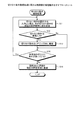
次に、推定範囲調整処理部42の動作について説明する。図15は、推定範囲調整処理に関わる制御部14の処理動作を示すフローチャートである。推定範囲調整処理部42は、図示せぬ再検索ボタンのボタン操作を検知すると(ステップS31)、現在選択済みの切り分け条件を取得する(ステップS32)。推定範囲調整処理部42は、現在選択済みの切り分け条件の内、1つの切り分け条件を除外対象に設定し(ステップS33)、除外対象の切り分け条件を除く、残りの切り分け条件を満たす原因を推定すべく、原因推定部35に指示する(ステップS34)。
Next, the operation of the estimated range adjustment processing unit 42 will be described. FIG. 15 is a flowchart showing the processing operation of the control unit 14 related to the estimated range adjustment processing. When the estimated range adjustment processing unit 42 detects a button operation of a re-search button (not shown) (step S31), the estimated range adjustment processing unit 42 acquires the currently selected separation condition (step S32). The estimation range adjustment processing unit 42 sets one of the currently selected separation conditions as an exclusion target (step S33), and estimates the cause of the remaining separation conditions excluding the exclusion target separation conditions. Therefore, the
推定範囲調整処理部42は、原因推定部35にて推定された原因候補を保持し(ステップS35)、除外対象の設定を解除し(ステップS36)、現在選択済みの切り分け条件の内、未だ除外対象未設定の切り分け条件が残っているか否かを判定する(ステップS37)。推定範囲調整処理部42は、除外対象未設定の切り分け条件が残っている場合(ステップS37肯定)、除外対象未設定の切り分け条件に対して除外対象を設定すべく、ステップS33に移行する。 The estimated range adjustment processing unit 42 holds the cause candidate estimated by the cause estimating unit 35 (step S35), cancels the setting of the exclusion target (step S36), and still excludes the currently selected separation conditions. It is determined whether or not an unset target separation condition remains (step S37). If there is a separation condition that is not set to be excluded (Yes in step S37), the estimated range adjustment processing unit 42 proceeds to step S33 in order to set an exclusion target for the separation condition that is not set to be excluded.
また、推定範囲調整処理部42は、除外対象未設定の切り分け条件が残っていない場合(ステップS37否定)、保持中の全原因候補を原因候補提示欄53に提示させるべく、原因候補提示部36に指示し(ステップS38)、この処理動作を終了する。その結果、切り分け条件を順次選択して原因を絞り込むことで現在の障害事例に該当する原因がなくなったとしても、再検索を実行することで、現在選択済みの切り分け条件で考え得る原因を提示できる。
In addition, the estimation range adjustment processing unit 42 causes the cause
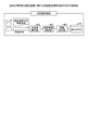
図16は、推定範囲調整処理部42に関わる動作の一例を示す説明図である。条件選択部34は、質問事項「遅延している処理」及び回答内容「オンライン処理」の切り分け条件、質問事項「特に遅延している処理」及び回答内容「両方」の切り分け条件、質問事項「遅くなった時期」及び回答内容「特定の時期から」の切り分け条件を選択したとする。 FIG. 16 is an explanatory diagram illustrating an example of operations related to the estimation range adjustment processing unit 42. The condition selection unit 34 separates the question item “delayed processing” and the answer content “online processing”, the question item “particularly delayed process” and the answer content “both”, and the question item “late”. It is assumed that the selection condition of “when has become” and the response content “from a certain time” has been selected.
この場合、原因候補提示部36は、1個の原因「業務量増加に伴ったCPU過負荷」を原因候補提示欄53上に提示することになる。しかしながら、ユーザは、原因「業務量増加に伴ったCPU過負荷」について調査したものの、現在の障害事例の原因に該当しなかった。そこで、推定範囲調整処理部42は、再検索ボタンのボタン操作を検出すると、次の切り分け条件の組合せパターンで原因を順次推定すべく、原因推定部35に指示する。
In this case, the cause
原因推定部35は、「遅くなった時期:特定の時期から」を除く、「遅延している処理:オンライン処理」及び「特に遅延している処理:両方」の切り分け条件を満たす原因を推定する。その結果、原因推定部35は、「リテラル値使用による解析コスト増大」、「FullGCによるレスポンス遅延」、「KeepAliveによるコネクション数不足」、「バッチ走行時のオンライン遅延」及び「業務量増加に伴ったCPU過負荷」の5種類の原因を推定し、その推定原因を保持する。
The
更に、原因推定部35は、「特に遅延している処理:両方」を除く、「遅延している処理:オンライン処理」及び「遅くなった時期:特定の時期から」の切り分け条件を満たす原因を推定する。その結果、原因推定部35は、「DB環境(アクセスパス変更)」及び「業務量増加に伴ったCPU過負荷」の2種類の原因を推定し、その推定原因を保持する。
Further, the
更に、原因推定部35は、「遅延している処理:オンライン処理」を除く、「特に遅延している処理:両方」及び「遅くなった時期:特定の時期から」の切り分け条件を満たす原因を推定する。その結果、原因推定部35は、「ウィルススキャンソフトのリアルタイムスキャン」、「大量ログ出力によるレスポンス遅延」及び「業務量増加に伴ったCPU過負荷」の3種類の原因を推定し、その推定原因を保持する。
Further, the
そして、原因候補提示部36は、保持中の推定原因の論理積をとり、8種類の原因候補を原因候補提示欄53上に提示することになる。
Then, the cause
また、実施例2の障害原因推定装置10を使用して、ソフトウェアパッケージの運用保守に関わる382件の障害事例に対して検証してみた。症状が38種類、問題のコンポーネントが7種類、直近の実行コマンドが31種類、エラーメッセージが90種類、連携しているアプリケーションが17種類の合計183種類の切り分け条件があった。全障害事例の内、古い282件から決定木を作成した。そして、新しい100件の内、古い282件と同一の障害事例30件に対して、作成した決定木を使用して原因を推定し、その解決率を評価した。更に、推定された原因は、切り分け条件を入力する度に絞り込まれ、最終的に複数存在し、そのうちに正しい原因が含まれるとして解決したとする。その結果、30件中の19件が提示された原因で解決し、従来の決定木による解決率がほぼ0%であったのに対し、本実施例の決定木による解決率は63%であった。その解決率が従来に比較して著しくアップしたことを証明している。
Further, the failure
実施例2では、ヒアリングDB22に登録済みの質問事項及び回答内容を切り分け条件として条件提示欄52上に提示し、その条件提示欄52上の切り分け条件を選択可能にし、その選択した切り分け条件を満たす原因候補を原因候補提示欄53上に提示する。その結果、従来の採取資料では得られなかった、ヒアリング等で得た質問事項及び回答内容に対応した切り分け条件を条件提示欄52上から選べる、すなわち、切り分け条件を型決めすることで、追加の切り分け条件の表記揺れを吸収できる。しかも、ヒアリング内容を反映した切り分け条件を登録することで、原因候補における推定精度の向上を図ることができる。
In the second embodiment, the question items and answer contents registered in the
実施例2では、原因候補提示欄53上に提示された原因から現在の障害事例に該当する原因を選択し、その選択した原因、当該原因を推定した全ての切り分け条件に関わる質問事項及び回答内容の組合せを現在の障害事例として障害事例DB21に追加登録する。その結果、ヒアリング内容を反映した切り分け条件に関する質問事項及び回答内容、原因を現在の障害事例として障害事例DB21に反映することでデータ内容の拡充を図ることができる。しかも、切り分け条件を選択しながら、現在の障害事例の原因を選択することになるため、従来のような原因の記述がないような障害事例の登録を確実に防止できる。その結果、ヒアリングによる切り分け条件と原因とを障害事例として障害事例DB21に登録することで、障害事例の再利用率の向上を図ることができる。
In the second embodiment, the cause corresponding to the current failure case is selected from the causes presented in the cause
実施例2では、条件提示欄52上に該当する切り分け条件がない場合でも、新規の質問事項や新規の回答内容を新規入力して新規の切り分け条件を入力できる。その結果、条件提示欄52上に該当する切り分け条件がない場合でも、その新規の質問事項や新規の回答内容を反映した切り分け条件を入力できると共に、その新規の切り分け条件を満たした原因候補を提示することもできる。更に、新規の切り分け条件を反映した障害事例を障害事例DB21に登録することでデータ内容の拡充を図ることができる。
In the second embodiment, even when there is no relevant separation condition on the
実施例2では、ヒアリングDB22に登録済みの切り分け条件を使用して、障害事例DB21に登録済みの障害事例毎の原因、質問事項及び回答内容を抽出し、これら障害事例毎の原因、質問事項及び回答内容に基づき決定木25を構築する。その結果、従来のような採取資料だけでなく、採取資料では得られなかったヒアリング内容を反映した決定木25を構築できる。
In the second embodiment, the cause, the question item, and the content of each failure case registered in the failure case DB 21 are extracted using the isolation condition registered in the
実施例2では、条件提示欄52上で切り分け条件を選択する度に、質問事項毎に選択可能性の高さを示す評価値を算出し、その評価値が高い順に質問事項の切り分け条件を条件提示欄52上に優先的に提示する。その結果、ユーザは、現時点での選択可能性の高い質問事項に関わる切り分け条件を条件提示欄52上で認識できるため、切り分け条件の選択作業性の向上を図ることができる。
In the second embodiment, each time the selection condition is selected on the
実施例2では、条件提示欄52上で切り分け条件を選択する度に、質問事項毎に選択可能性の高さを示す評価値を算出し、その評価値が基準閾値以下の場合、その質問事項の切り分け条件の条件提示欄52上への提示を禁止する。その結果、現時点での選択可能性の極めて低い質問事項に関わる切り分け条件の提示を無くすことで、その切り分け条件の選択作業性の向上を図ることができる。
In the second embodiment, each time a selection condition is selected on the
実施例2では、切り分け条件を順次選択して原因を絞り込むことで現在の障害事例に該当する原因がなくなったとしても、再検索を実行することで、選択済みの切り分け条件毎に、その切り分け条件を除く、選択済みの全ての切り分け条件を満たす原因を順次推定する。その結果、ワンタッチ操作で現在の選択済みの切り分け条件で考え得る原因を全て原因候補提示欄53上に提示できる。
In Example 2, even if the cause corresponding to the current failure case disappears by narrowing down the cause by sequentially selecting the separation condition, by performing a re-search, the separation condition is determined for each selected separation condition. The causes that satisfy all the selected separation conditions except for are sequentially estimated. As a result, all possible causes can be presented on the cause
尚、上記実施例では、優先表示処理部41にてエントロピーで評価するようにしたが、Giniインデックス等の他の指標を使用しても良い。また、上記実施例では、図13の優先表示処理のステップS22にて切り分け条件の入力状態を取得する際、取り得る入力状態の全てについて、それ以降の計算を行いエントロピーが高い上位3位までの質問事項を計算して保存した。その結果、保存内容に基づき、迅速に優先表示処理を実現できる。
In the above embodiment, the priority
また、図示した各部の各構成要素は、必ずしも物理的に図示の如く構成されていることを要しない。すなわち、各部の分散・統合の具体的形態は図示のものに限られず、その全部又は一部を、各種の負荷や使用状況等に応じて、任意の単位で機能的又は物理的に分散・統合して構成することができる。 In addition, each component of each part illustrated does not necessarily need to be physically configured as illustrated. In other words, the specific form of distribution / integration of each part is not limited to the one shown in the figure, and all or a part thereof may be functionally or physically distributed / integrated in arbitrary units according to various loads and usage conditions. Can be configured.
更に、各装置で行われる各種処理機能は、CPU(Central Processing Unit)(又はMPU(Micro Processing Unit)、MCU(Micro Controller Unit)等のマイクロ・コンピュータ)上で、その全部又は任意の一部を実行するようにしても良い。また、各種処理機能は、CPU(又はMPU、MCU等のマイクロ・コンピュータ)で解析実行するプログラム上、又はワイヤードロジックによるハードウェア上で、その全部又は任意の一部を実行するようにしても良いことは言うまでもない。 Furthermore, various processing functions performed in each device are performed on a CPU (Central Processing Unit) (or a microcomputer such as an MPU (Micro Processing Unit), MCU (Micro Controller Unit), etc.) in whole or in part. You may make it perform. Various processing functions may be executed entirely or arbitrarily on a program that is analyzed and executed by a CPU (or a microcomputer such as an MPU or MCU) or hardware based on wired logic. Needless to say.
ところで、本実施例で説明した各種の処理は、予め用意されたプログラムをコンピュータで実行することによって実現することができる。そこで、以下では、図17を用いて、上記の実施例と同様の機能を有するプログラムを実行するコンピュータの一例を説明する。図17は、障害原因推定プログラムを実行するコンピュータを示す説明図である。 By the way, the various processes described in the present embodiment can be realized by executing a prepared program on a computer. In the following, an example of a computer that executes a program having the same function as that of the above embodiment will be described with reference to FIG. FIG. 17 is an explanatory diagram of a computer that executes a failure cause estimation program.
同図に示すように、障害原因推定プログラムとしてのコンピュータ200は、HDD(Hard Disk Drive)210、RAM(Random Access Memory)220、ROM(Read Only Memory)230及びCPU240をバス250で接続して構成される。
As shown in the figure, a
そして、ROM230には、上記の実施例と同様の機能を発揮する障害原因推定プログラム、つまり、図17に示すように、管理プログラム231、条件提示プログラム232、条件選択プログラム233、原因推定プログラム234及び原因候補提示プログラム235が予め記憶されている。尚、プログラム231〜235については、図1に示した障害原因推定装置の各構成要素と同様、適宜統合又は分散してもよい。
The ROM 230 stores a failure cause estimation program that exhibits the same function as that of the above embodiment, that is, as shown in FIG. 17, a
そして、CPU240が、これらのプログラム231〜235をROM230から読み出して実行することで、図17に示すように、各プログラム231〜235は、管理プロセス241、条件提示プロセス242、条件選択プロセス243、原因推定プロセス244及び原因候補提示プロセス245として機能するようになる。
Then, the CPU 240 reads out these
CPU240は、過去の障害事例に関する原因、質問事項及び当該質問事項に対する回答内容を前記障害事例毎にHDD210に管理する。更に、CPU240は、HDD210に管理された質問事項と当該質問事項に対する回答内容との組合せを、障害事例の原因を区分する切り分け条件として表示画面上で提示する。更に、CPU240は、提示された切り分け条件の内、選択操作に応じて、少なくとも一つの切り分け条件を選択する。更に、CPU240は、選択操作に応じて、選択された切り分け条件を満たす原因をHDD210の内容から推定する。更に、CPU240は、推定された各原因を原因候補として表示画面上で提示する。
The CPU 240 manages causes, questions, and contents of answers to the questions regarding past failure cases in the
その結果、従来の採取資料では得られなかった、ヒアリング等で得た質問事項及び回答内容に対応した切り分け条件を表示画面上から選べるため、切り分け条件の表記揺れを吸収できる。しかも、ヒアリング内容を反映した切り分け条件を取得することで原因候補の推定精度の向上が図れる。 As a result, since it is possible to select from the display screen the separation conditions corresponding to the question items and answer contents obtained through interviews, etc., which could not be obtained with conventional collection materials, it is possible to absorb the fluctuation of the separation conditions. In addition, it is possible to improve the estimation accuracy of the cause candidate by acquiring the separation condition reflecting the hearing contents.
以上、本実施例を含む実施の形態に関し、更に以下の付記を開示する。 As described above, the following supplementary notes are further disclosed regarding the embodiment including the present example.
(付記1)過去の障害事例に関する原因、質問事項及び当該質問事項に対する回答内容を前記障害事例毎に管理するデータベースと、
前記データベースに管理された前記質問事項と当該質問事項に対する前記回答内容との組合せを、前記障害事例の原因を区分する切り分け条件として表示画面上で提示する条件提示部と、
前記条件提示部にて提示された前記切り分け条件の内、選択操作に応じて、少なくとも一つの切り分け条件を選択する条件選択部と、
前記条件選択部にて選択された切り分け条件を満たす原因を前記データベースの内容から推定する原因推定部と、
前記原因推定部にて推定された各原因を原因候補として前記表示画面上で提示する原因候補提示部と
を有することを特徴とする障害原因推定装置。
(Supplementary note 1) A database for managing the cause, questions, and contents of answers to the questions regarding past failures, for each of the failures,
A condition presentation unit that presents a combination of the question items managed in the database and the answer content to the question items on a display screen as a separation condition for classifying the cause of the failure case;
A condition selection unit that selects at least one separation condition according to a selection operation among the separation conditions presented by the condition presentation unit;
A cause estimating unit for estimating a cause satisfying the separation condition selected by the condition selecting unit from the contents of the database;
A failure cause estimation apparatus comprising: a cause candidate presenting unit that presents each cause estimated by the cause estimating unit as a cause candidate on the display screen.
(付記2)前記原因候補提示部にて提示された原因候補の内、選択操作に応じて任意の原因候補を原因として選択する原因候補選択部と、
追加登録操作に応じて、前記原因候補選択部にて選択された原因及び、当該原因を推定した切り分け条件に関わる前記質問事項及び前記回答内容の組合せを新規の障害事例として前記データベースに追加登録する追加登録部と
を有することを特徴とする付記1記載の障害原因推定装置。
(Supplementary Note 2) Among the cause candidates presented by the cause candidate presenting unit, a cause candidate selecting unit that selects an arbitrary cause candidate as a cause according to a selection operation;
In accordance with the additional registration operation, the cause selected by the cause candidate selection unit and the combination of the question item and the answer content related to the isolation condition for estimating the cause are additionally registered in the database as a new failure case. The failure cause estimation device according to
(付記3)前記条件選択部は、
新規の質問事項又は新規の回答内容を入力可能とする新規入力部を有し、
前記新規入力部の入力操作に応じて、前記新規の質問事項と当該質問事項に対する新規の回答内容との組合せ又は、前記条件提示部にて提示された質問事項と当該質問事項に対する新規の回答内容との組合せを切り分け条件として選択することを特徴とする付記1又は2に記載の障害原因推定装置。
(Appendix 3) The condition selection unit
It has a new input section that allows you to input new questions or new answers,
In accordance with the input operation of the new input unit, a combination of the new question item and the new answer content for the question item, or the question item presented in the condition presenting unit and the new answer content for the question item The failure cause estimation apparatus according to
(付記4)前記データベースにて前記障害事例毎に管理された前記原因、前記質問事項及び前記回答内容に基づき、推定対象の障害事例の原因を推定する際に使用する決定木を構築する決定木構築部を有し、
前記原因推定部は、
前記条件選択部にて選択された切り分け条件を満たす原因を前記決定木から推定することを特徴とする付記1〜3の何れか一つに記載の障害原因推定装置。
(Additional remark 4) Decision tree which builds a decision tree used when estimating the cause of the failure case of the estimation object based on the cause, the question item, and the content of the answer managed for each failure case in the database Has a construction department,
The cause estimator is
The failure cause estimation apparatus according to any one of
(付記5)前記条件提示部は、
前記条件選択部にて切り分け条件を選択する毎に、選択可能性の高さを示す評価値を質問事項毎に算出し、前記評価値が高い順に、当該質問事項の切り分け条件を前記表示画面上で提示することを特徴とする付記1〜4の何れか一つに記載の障害原因推定装置。
(Supplementary Note 5) The condition presentation unit
Each time the selection condition is selected by the condition selection unit, an evaluation value indicating a high possibility of selection is calculated for each question item, and the separation conditions for the question item are displayed on the display screen in descending order of the evaluation value. The failure cause estimation device according to any one of
(付記6)前記条件提示部は、
前記評価値が基準閾値以下の場合、当該評価値の質問事項に関わる切り分け条件の前記表示画面上への提示を禁止することを特徴とする付記5記載の障害原因推定装置。
(Appendix 6) The condition presentation unit
The failure cause estimation apparatus according to
(付記7)前記原因推定部は、
前記条件選択部にて選択された切り分け条件を満たす原因を推定した場合、再検索操作を検出すると、当該条件選択部にて選択された切り分け条件毎に、その切り分け条件を除く、当該条件選択部にて選択された切り分け条件を満たす原因を順次推定すると共に、
前記原因候補提示部は、
前記原因推定部にて順次推定された原因を原因候補として前記表示画面上で提示することを特徴とする付記1〜6の何れか一つに記載の障害原因推定装置。
(Supplementary Note 7) The cause estimating unit
When the cause that satisfies the separation condition selected by the condition selection unit is estimated, and the re-search operation is detected, the condition selection unit that excludes the separation condition for each separation condition selected by the condition selection unit In addition to sequentially estimating the cause satisfying the carving condition selected in,
The cause candidate presenting unit
The failure cause estimation apparatus according to any one of
(付記8)過去の障害事例に関する原因、質問事項及び当該質問事項に対する回答内容を前記障害事例毎にデータベースに管理する管理手順と、
前記データベースに管理された前記質問事項と当該質問事項に対する前記回答内容との組合せを、前記障害事例の原因を区分する切り分け条件として表示画面上で提示する条件提示手順と、
前記条件提示手順にて提示された前記切り分け条件の内、選択操作に応じて、少なくとも一つの切り分け条件を選択する条件選択手順と、
前記条件選択手順にて選択された切り分け条件を満たす原因を前記データベースの内容から推定する原因推定手順と、
前記原因推定手順にて推定された各原因を原因候補として前記表示画面上で提示する原因候補提示手順と
を含むプログラムをコンピュータに実行させることを特徴とする障害原因推定プログラム。
(Supplementary note 8) Management procedures for managing causes, questions, and contents of responses to questions in the past in the database for each case,
A condition presentation procedure for presenting a combination of the question items managed in the database and the content of the answer to the question items on a display screen as a separation condition for classifying the cause of the failure case,
A condition selection procedure for selecting at least one separation condition in accordance with a selection operation among the separation conditions presented in the condition presentation procedure;
A cause estimation procedure for estimating the cause satisfying the separation condition selected in the condition selection procedure from the contents of the database;
A failure cause estimation program that causes a computer to execute a program including a cause candidate presentation procedure that presents each cause estimated in the cause estimation procedure as a cause candidate on the display screen.
(付記9)過去の障害事例に関する原因、質問事項及び当該質問事項に対する回答内容を前記障害事例毎にデータベースに管理する管理ステップと、
前記データベースに管理された前記質問事項と当該質問事項に対する前記回答内容との組合せを、前記障害事例の原因を区分する切り分け条件として表示画面上で提示する条件提示ステップと、
前記条件提示ステップにて提示された前記切り分け条件の内、選択操作に応じて、少なくとも一つの切り分け条件を選択する条件選択ステップと、
前記条件選択ステップにて選択された切り分け条件を満たす原因を前記データベースの内容から推定する原因推定ステップと、
前記原因推定ステップにて推定された各原因を原因候補として前記表示画面上で提示する原因候補提示ステップと
を有することを特徴とする障害原因推定方法。
(Supplementary Note 9) Management steps for managing causes, questions, and contents of responses to the questions in the past in the database for each case,
A condition presenting step for presenting a combination of the question items managed in the database and the content of the answer to the question items on a display screen as a separation condition for classifying the cause of the failure case;
A condition selection step for selecting at least one of the separation conditions according to a selection operation among the separation conditions presented in the condition presentation step;
A cause estimation step of estimating a cause satisfying the separation condition selected in the condition selection step from the contents of the database;
And a cause candidate presenting step for presenting each cause estimated in the cause estimating step as a cause candidate on the display screen.
1 障害原因推定装置
2 表示部
3 DB
4 制御部
5 条件提示部
6 条件選択部
7 原因推定部
8 原因候補提示部
10 障害原因推定装置
11 表示部
12 操作部
13 DB
14 制御部
21 障害事例DB
22 ヒアリングDB
23 決定木DB
31 入力インタフェース生成部
33 条件提示部
34 条件選択部
35 原因推定部
36 原因候補提示部
37 原因候補選択部
38 追加登録部
39 新規追加部
40 決定木構築処理部
41 優先表示処理部
42 推定範囲調整処理部
1 failure
DESCRIPTION OF
14 Control unit 21 Failure case DB
22 Hearing DB
23 Decision Tree DB
31 Input
Claims (7)
前記障害事例の原因を区分するための前記質問事項と前記回答内容との組合せとして記憶した第2のデータベースと、
前記第2のデータベースから前記質問事項と前記回答内容との組合せを切り分け条件として提示する条件提示部と、
前記切り分け条件に提示されていない質問事項と回答内容との組合せである新規の切り分け条件の入力を受け付ける受付部と、
前記新規の切り分け条件を前記第2のデータベースに記憶する記憶制御部と、
前記提示された前記切り分け条件の中から選択した切り分け条件及び前記新規の切り分け条件を満たす障害事例の原因を前記第1のデータベースから推定する原因推定部と、
前記推定された前記原因を原因候補として提示する原因候補提示部と、
前記原因候補提示部にて提示された原因候補の中から任意の原因候補を原因として選択する原因候補選択部と、
追加登録操作に応じて、前記原因候補選択部にて選択された原因及び、当該原因を推定した切り分け条件の前記質問事項及び前記回答内容を新規の障害事例として前記第1のデータベースに記憶すると共に、前記新規の障害事例の原因を区分するための前記質問事項と前記回答内容との組合せを前記第2のデータベースに記憶する前記記憶制御部と
を有することを特徴とする障害原因推定装置。 A first database that stores the cause, question, and answer to the question regarding past failure cases for each failure case;
A second database stored as a combination of the questionnaire and the answer content for classifying the cause of the failure case;
A condition presentation unit that presents a combination of the question item and the answer content from the second database as a separation condition;
A reception unit that receives an input of a new carving condition that is a combination of a question and a response content that are not presented in the carving condition;
A storage control unit for storing the new carving condition in the second database;
A cause estimation unit that estimates from the first database the cause of a failure case that satisfies the new separation condition and the separation condition selected from the presented separation conditions;
A cause candidate presenting section for presenting the estimated cause as a cause candidate ;
A cause candidate selection unit that selects an arbitrary cause candidate as a cause from among the cause candidates presented by the cause candidate presenting unit;
In response to the additional registration operation, the cause selected by the cause candidate selection unit and the question item and the answer content of the separation condition for estimating the cause are stored in the first database as a new failure case. A failure cause comprising: the storage control unit for storing a combination of the question item and the answer content for classifying the cause of the new failure case in the second database. Estimating device.
前記新規入力部の入力操作に応じて、前記新規の質問事項と当該質問事項に対する新規の回答内容との組合せ又は、前記条件提示部にて提示された質問事項と当該質問事項に対する新規の回答内容との組合せを切り分け条件として選択する条件選択部と
を有することを特徴とする請求項1に記載の障害原因推定装置。 A new input section that allows input of new questions or new answers,
In accordance with the input operation of the new input unit, a combination of the new question item and the new answer content for the question item, or the question item presented in the condition presenting unit and the new answer content for the question item The failure cause estimation apparatus according to claim 1 , further comprising: a condition selection unit that selects a combination of the two as a separation condition.
前記切り分け条件を選択する毎に、選択可能性の高さを示す評価値を質問事項毎に算出し、前記評価値が高い順に、当該質問事項の切り分け条件を提示することを特徴とする請求項1又は2に記載の障害原因推定装置。 The condition presentation unit
Each time the selection condition is selected, an evaluation value indicating a high degree of selectability is calculated for each question item, and the determination condition for the question item is presented in descending order of the evaluation value. The failure cause estimation apparatus according to 1 or 2 .
前記評価値が基準閾値以下の場合、当該評価値の質問事項に関わる切り分け条件の提示を禁止することを特徴とする請求項3に記載の障害原因推定装置。 The condition presentation unit
The failure cause estimation apparatus according to claim 3 , wherein when the evaluation value is equal to or less than a reference threshold, presentation of a separation condition related to a question item of the evaluation value is prohibited.
前記選択された切り分け条件を満たす原因を推定した場合、再検索操作を検出すると、当該選択された切り分け条件毎に、その切り分け条件を除く、当該選択された切り分け条件を満たす原因を順次推定すると共に、
前記原因候補提示部は、
前記原因推定部にて順次推定された原因を原因候補として提示することを特徴とする請求項1〜4の何れか一つに記載の障害原因推定装置。 The cause estimator is
When the cause that satisfies the selected carving condition is estimated, when a re-search operation is detected, the cause that satisfies the selected carving condition is sequentially estimated for each selected carving condition, excluding the carving condition. ,
The cause candidate presenting unit
The cause estimated sequentially in the said cause estimation part is shown as a cause candidate, The failure cause estimation apparatus as described in any one of Claims 1-4 characterized by the above-mentioned.
過去の障害事例に関する原因、質問事項及び質問事項に対する回答内容を前記障害事例毎に記憶する第1のデータベースと、前記障害事例の原因を区分するための前記質問事項と前記回答内容との組合せとして記憶する第2のデータベースとをアクセス可能な状態にし、
前記第2のデータベースから前記質問事項と前記回答内容との組合せを切り分け条件として提示し、
前記切り分け条件に提示されていない質問事項と回答内容との組合せである新規の切り分け条件の入力を受け付け、
前記新規の切り分け条件を前記第2のデータベースに記憶し、
前記提示された前記切り分け条件の中から選択した切り分け条件及び前記新規の切り分け条件を満たす障害事例の原因を前記第1データベースから推定し、
前記推定された前記原因を原因候補として提示し、
前記提示された原因候補の中から任意の原因候補を原因として選択し、
追加登録操作に応じて、前記選択された原因及び、当該原因を推定した切り分け条件の前記質問事項及び前記回答内容を新規の障害事例として前記第1のデータベースに記憶すると共に、前記新規の障害事例の原因を区分するための前記質問事項と前記回答内容との組合せを前記第2のデータベースに記憶する
処理を実行させることを特徴とする障害原因推定プログラム。 On the computer,
As a combination of the first database for storing the cause, the question items and the answer contents for the past trouble cases for each trouble case, the question items for classifying the cause of the trouble case, and the answer contents Make the second database to be accessible accessible,
Presenting the combination of the question and the answer content from the second database as a separation condition,
Accepting an input of a new carving condition that is a combination of a question and an answer content not presented in the carving condition,
Storing the new carving condition in the second database;
Inferring from the first database the cause of a failure case that satisfies the new carving condition and the carving condition selected from the presented carving conditions,
Presenting the estimated cause as a cause candidate ,
Select any cause candidate from the presented cause candidates as a cause,
In response to an additional registration operation, the selected cause and the question item and the answer content of the isolation condition that estimated the cause are stored in the first database as a new failure case, and the new failure case A failure cause estimation program characterized by causing the second database to execute a process of storing a combination of the question item and the answer content for classifying the cause of the problem in the second database .
過去の障害事例に関する原因、質問事項及び質問事項に対する回答内容を前記障害事例毎に記憶する第1のデータベースと、前記障害事例の原因を区分するための前記質問事項と前記回答内容との組合せとして記憶する第2のデータベースとをアクセス可能にし、
前記第2のデータベースから前記質問事項と前記回答内容との組合せを切り分け条件として提示し、
前記切り分け条件に提示されていない質問事項と回答内容との組合せである新規の切り分け条件の入力を受け付け、
前記新規の切り分け条件を前記第2のデータベースに記憶し、
前記提示された前記切り分け条件の中から選択した切り分け条件及び前記新規の切り分け条件を満たす障害事例の原因を前記第1データベースから推定し、
前記推定された前記原因を原因候補として提示し、
前記提示された原因候補の中から任意の原因候補を原因として選択し、
追加登録操作に応じて、前記選択された原因及び、当該原因を推定した切り分け条件の前記質問事項及び前記回答内容を新規の障害事例として前記第1のデータベースに記憶すると共に、前記新規の障害事例の原因を区分するための前記質問事項と前記回答内容との組合せを前記第2のデータベースに記憶する
処理を実行することを特徴とする障害原因推定方法。 Computer
As a combination of the first database for storing the cause, the question items and the answer contents for the past trouble cases for each trouble case, the question items for classifying the cause of the trouble case, and the answer contents Make the second database to be accessible accessible,
Presenting the combination of the question and the answer content from the second database as a separation condition,
Accepting an input of a new carving condition that is a combination of a question and an answer content not presented in the carving condition,
Storing the new carving condition in the second database;
Inferring from the first database the cause of a failure case that satisfies the new carving condition and the carving condition selected from the presented carving conditions,
Presenting the estimated cause as a cause candidate ,
Select any cause candidate from the presented cause candidates as a cause,
In response to an additional registration operation, the selected cause and the question item and the answer content of the isolation condition that estimated the cause are stored in the first database as a new failure case, and the new failure case A failure cause estimation method comprising: executing a process of storing a combination of the question item and the answer content for classifying the cause of the error in the second database .
Priority Applications (2)
| Application Number | Priority Date | Filing Date | Title |
|---|---|---|---|
| JP2010137601A JP5521807B2 (en) | 2010-06-16 | 2010-06-16 | Failure cause estimation apparatus, failure cause estimation program, and failure cause estimation method |
| US13/064,462 US8499195B2 (en) | 2010-06-16 | 2011-03-25 | Failure cause estimation device and failure cause estimation method |
Applications Claiming Priority (1)
| Application Number | Priority Date | Filing Date | Title |
|---|---|---|---|
| JP2010137601A JP5521807B2 (en) | 2010-06-16 | 2010-06-16 | Failure cause estimation apparatus, failure cause estimation program, and failure cause estimation method |
Publications (3)
| Publication Number | Publication Date |
|---|---|
| JP2012003497A JP2012003497A (en) | 2012-01-05 |
| JP2012003497A5 JP2012003497A5 (en) | 2013-06-20 |
| JP5521807B2 true JP5521807B2 (en) | 2014-06-18 |
Family
ID=45329759
Family Applications (1)
| Application Number | Title | Priority Date | Filing Date |
|---|---|---|---|
| JP2010137601A Expired - Fee Related JP5521807B2 (en) | 2010-06-16 | 2010-06-16 | Failure cause estimation apparatus, failure cause estimation program, and failure cause estimation method |
Country Status (2)
| Country | Link |
|---|---|
| US (1) | US8499195B2 (en) |
| JP (1) | JP5521807B2 (en) |
Families Citing this family (9)
| Publication number | Priority date | Publication date | Assignee | Title |
|---|---|---|---|---|
| US9104572B1 (en) * | 2013-02-11 | 2015-08-11 | Amazon Technologies, Inc. | Automated root cause analysis |
| JP6664072B2 (en) * | 2015-12-02 | 2020-03-13 | パナソニックIpマネジメント株式会社 | Search support method, search support device, and program |
| JP6803754B2 (en) * | 2017-01-16 | 2020-12-23 | 株式会社日立製作所 | Log message grouping device, log message grouping system and log message grouping method |
| CN107679154B (en) * | 2017-09-27 | 2020-04-21 | 哈尔滨工业大学深圳研究生院 | Method, system and medium for solving historical problems based on time axis |
| CN107871004A (en) * | 2017-11-14 | 2018-04-03 | 国家电网公司 | A kind of power distribution network analysis of prices management system |
| JP2020052857A (en) * | 2018-09-28 | 2020-04-02 | 大和ハウス工業株式会社 | Estimation system and estimation method |
| US11042320B2 (en) * | 2019-02-18 | 2021-06-22 | International Business Machines Corporation | Problem diagnosis in complex SAN environments |
| WO2021072687A1 (en) * | 2019-10-16 | 2021-04-22 | 西门子(中国)有限公司 | Fault processing method and system, and computer readable medium |
| JP7333281B2 (en) * | 2020-02-06 | 2023-08-24 | 株式会社日立製作所 | Design support system |
Family Cites Families (24)
| Publication number | Priority date | Publication date | Assignee | Title |
|---|---|---|---|---|
| US4857918A (en) * | 1986-02-25 | 1989-08-15 | Kabushiki Kaisha Toshiba | Fault diagnostic apparatus for electric appliance |
| JP3224226B2 (en) * | 1989-09-22 | 2001-10-29 | 株式会社リコー | Fault diagnosis expert system |
| SE467026B (en) * | 1990-09-21 | 1992-05-11 | Televerket | DEVICE FOR STRUCTURING TECHNICAL INFORMATION WHEN CREATING A KNOWLEDGE DATABASE AND TROUBLESHOOTING IN TECHNICAL EQUIPMENT |
| JPH05282155A (en) * | 1992-03-31 | 1993-10-29 | Nec Corp | Knowledge information processing system |
| JPH0877260A (en) * | 1994-09-09 | 1996-03-22 | Hitachi Electron Service Co Ltd | Fault measure support system |
| JP2003108689A (en) * | 2001-09-26 | 2003-04-11 | Nec Fielding Ltd | Inquiry processing system and method for breakdown and its program |
| KR100429883B1 (en) * | 2001-12-20 | 2004-05-03 | 삼성전자주식회사 | Method for measuring fail probability by only defect, method for measuring defect limited yield using classification the extracted defect pattern's parameter, and system for measuring fail probability by only defect and the defect limited yield |
| US20040260678A1 (en) * | 2003-06-18 | 2004-12-23 | Microsoft Corporation | State based configuration failure detection using checkpoint comparison |
| JP2005251091A (en) | 2004-03-08 | 2005-09-15 | Konica Minolta Holdings Inc | Data processor, data processing method, and data processing program |
| JP2005309077A (en) * | 2004-04-21 | 2005-11-04 | Fuji Xerox Co Ltd | Fault diagnostic method, fault diagnostic system, transporting device, and image forming apparatus, and program and storage medium |
| US20050283682A1 (en) * | 2004-06-18 | 2005-12-22 | Hitachi, Ltd. | Method for data protection in disk array systems |
| JP4314200B2 (en) * | 2005-02-02 | 2009-08-12 | Necフィールディング株式会社 | Maintenance support system, maintenance management device and program |
| JP2006301820A (en) * | 2005-04-19 | 2006-11-02 | Hitachi Ltd | Storage system and data migration method for storage system |
| US7899638B2 (en) * | 2005-10-18 | 2011-03-01 | Lecroy Corporation | Estimating bit error rate performance of signals |
| JP4055800B2 (en) * | 2005-12-29 | 2008-03-05 | ダイキン工業株式会社 | Specific equipment management device |
| JP2007323558A (en) | 2006-06-05 | 2007-12-13 | Nippon Telegr & Teleph Corp <Ntt> | Keyword generator, and document retrieval device, method and program |
| JP4562713B2 (en) * | 2006-10-05 | 2010-10-13 | ルネサスエレクトロニクス株式会社 | Fault location estimation system for multiple faults in logic circuit, fault location estimation method, and fault location estimation program |
| DE102007000999B4 (en) * | 2007-02-26 | 2012-06-28 | Vistec Semiconductor Systems Gmbh | Method for eliminating error sources of the system correction of a coordinate measuring machine |
| US8196004B1 (en) * | 2007-03-27 | 2012-06-05 | Marvell International Ltd. | Fast erasure decoding for product code columns |
| US7656518B2 (en) * | 2007-03-30 | 2010-02-02 | Asml Netherlands B.V. | Method of measuring asymmetry in a scatterometer, a method of measuring an overlay error in a substrate and a metrology apparatus |
| US7616007B2 (en) * | 2007-07-23 | 2009-11-10 | Advantest Corporation | Device, method, program, and recording medium for error factor measurement, and output correction device and reflection coefficient measurement device provided with the device for error factor measurement |
| US9152530B2 (en) * | 2009-05-14 | 2015-10-06 | Oracle America, Inc. | Telemetry data analysis using multivariate sequential probability ratio test |
| JP5270458B2 (en) * | 2009-06-12 | 2013-08-21 | ルネサスエレクトロニクス株式会社 | Fault location estimation device |
| JP5447092B2 (en) * | 2010-03-30 | 2014-03-19 | 富士通株式会社 | Processing apparatus, data migration method, and data migration program |
-
2010
- 2010-06-16 JP JP2010137601A patent/JP5521807B2/en not_active Expired - Fee Related
-
2011
- 2011-03-25 US US13/064,462 patent/US8499195B2/en active Active
Also Published As
| Publication number | Publication date |
|---|---|
| US8499195B2 (en) | 2013-07-30 |
| US20110314332A1 (en) | 2011-12-22 |
| JP2012003497A (en) | 2012-01-05 |
Similar Documents
| Publication | Publication Date | Title |
|---|---|---|
| JP5521807B2 (en) | Failure cause estimation apparatus, failure cause estimation program, and failure cause estimation method | |
| US11928118B2 (en) | Generating a correlation search | |
| US11748394B1 (en) | Using indexers from multiple systems | |
| US11386109B2 (en) | Sharing configuration information through a shared storage location | |
| US10439922B2 (en) | Service analyzer interface | |
| JP6233411B2 (en) | Fault analysis apparatus, fault analysis method, and computer program | |
| US9621571B2 (en) | Apparatus and method for searching for similar malicious code based on malicious code feature information | |
| US9582585B2 (en) | Discovering fields to filter data returned in response to a search | |
| US10860655B2 (en) | Creating and testing a correlation search | |
| US20150121136A1 (en) | System and method for automatically managing fault events of data center | |
| US10635507B2 (en) | Event monitoring apparatus and event monitoring method | |
| JP2018206316A (en) | Plant operation monitoring system and plant operation monitoring method | |
| US10261998B2 (en) | Search apparatus and search method | |
| JP2007304796A (en) | Database analysis system, database analysis method and program | |
| JP5395719B2 (en) | Rule generation device and program for failure cause analysis system | |
| JP6276668B2 (en) | Failure analysis system | |
| JP2016224856A (en) | Database device, retrieval device, subgraph construction method and retrieval method | |
| US20230267033A1 (en) | Recommending remediation actions for incidents identified by performance management systems | |
| JP5623950B2 (en) | IT failure sign detection device and program | |
| JP7097408B2 (en) | Methods, devices, electronic devices and storage media for treating local hotspots | |
| US20200293290A1 (en) | Template creation apparatus, computer readable medium and template creation method | |
| JP2011186706A (en) | Information processor, information processing method, and program | |
| JP2011118575A (en) | Failure countermeasure information acquisition method and management server | |
| JP6852002B2 (en) | Data search method, data search device and program | |
| JP6613634B2 (en) | Search support program, search support apparatus, and search support method |
Legal Events
| Date | Code | Title | Description |
|---|---|---|---|
| A521 | Request for written amendment filed |
Free format text: JAPANESE INTERMEDIATE CODE: A523 Effective date: 20130501 |
|
| A621 | Written request for application examination |
Free format text: JAPANESE INTERMEDIATE CODE: A621 Effective date: 20130507 |
|
| A977 | Report on retrieval |
Free format text: JAPANESE INTERMEDIATE CODE: A971007 Effective date: 20131217 |
|
| A131 | Notification of reasons for refusal |
Free format text: JAPANESE INTERMEDIATE CODE: A131 Effective date: 20131224 |
|
| A521 | Request for written amendment filed |
Free format text: JAPANESE INTERMEDIATE CODE: A523 Effective date: 20140219 |
|
| TRDD | Decision of grant or rejection written | ||
| A01 | Written decision to grant a patent or to grant a registration (utility model) |
Free format text: JAPANESE INTERMEDIATE CODE: A01 Effective date: 20140311 |
|
| A61 | First payment of annual fees (during grant procedure) |
Free format text: JAPANESE INTERMEDIATE CODE: A61 Effective date: 20140324 |
|
| R150 | Certificate of patent or registration of utility model |
Ref document number: 5521807 Country of ref document: JP Free format text: JAPANESE INTERMEDIATE CODE: R150 |
|
| LAPS | Cancellation because of no payment of annual fees |