JP5501622B2 - Time duplication device and method for radar sensor front end - Google Patents
Time duplication device and method for radar sensor front end Download PDFInfo
- Publication number
- JP5501622B2 JP5501622B2 JP2008549497A JP2008549497A JP5501622B2 JP 5501622 B2 JP5501622 B2 JP 5501622B2 JP 2008549497 A JP2008549497 A JP 2008549497A JP 2008549497 A JP2008549497 A JP 2008549497A JP 5501622 B2 JP5501622 B2 JP 5501622B2
- Authority
- JP
- Japan
- Prior art keywords
- antenna
- frequency
- signal
- waveform
- radar
- Prior art date
- Legal status (The legal status is an assumption and is not a legal conclusion. Google has not performed a legal analysis and makes no representation as to the accuracy of the status listed.)
- Expired - Fee Related
Links
Images


Classifications
-
- G—PHYSICS
- G01—MEASURING; TESTING
- G01S—RADIO DIRECTION-FINDING; RADIO NAVIGATION; DETERMINING DISTANCE OR VELOCITY BY USE OF RADIO WAVES; LOCATING OR PRESENCE-DETECTING BY USE OF THE REFLECTION OR RERADIATION OF RADIO WAVES; ANALOGOUS ARRANGEMENTS USING OTHER WAVES
- G01S13/00—Systems using the reflection or reradiation of radio waves, e.g. radar systems; Analogous systems using reflection or reradiation of waves whose nature or wavelength is irrelevant or unspecified
- G01S13/02—Systems using reflection of radio waves, e.g. primary radar systems; Analogous systems
- G01S13/50—Systems of measurement based on relative movement of target
- G01S13/58—Velocity or trajectory determination systems; Sense-of-movement determination systems
- G01S13/583—Velocity or trajectory determination systems; Sense-of-movement determination systems using transmission of continuous unmodulated waves, amplitude-, frequency-, or phase-modulated waves and based upon the Doppler effect resulting from movement of targets
- G01S13/584—Velocity or trajectory determination systems; Sense-of-movement determination systems using transmission of continuous unmodulated waves, amplitude-, frequency-, or phase-modulated waves and based upon the Doppler effect resulting from movement of targets adapted for simultaneous range and velocity measurements
-
- G—PHYSICS
- G01—MEASURING; TESTING
- G01S—RADIO DIRECTION-FINDING; RADIO NAVIGATION; DETERMINING DISTANCE OR VELOCITY BY USE OF RADIO WAVES; LOCATING OR PRESENCE-DETECTING BY USE OF THE REFLECTION OR RERADIATION OF RADIO WAVES; ANALOGOUS ARRANGEMENTS USING OTHER WAVES
- G01S13/00—Systems using the reflection or reradiation of radio waves, e.g. radar systems; Analogous systems using reflection or reradiation of waves whose nature or wavelength is irrelevant or unspecified
- G01S13/02—Systems using reflection of radio waves, e.g. primary radar systems; Analogous systems
- G01S13/06—Systems determining position data of a target
- G01S13/08—Systems for measuring distance only
- G01S13/32—Systems for measuring distance only using transmission of continuous waves, whether amplitude-, frequency-, or phase-modulated, or unmodulated
- G01S13/34—Systems for measuring distance only using transmission of continuous waves, whether amplitude-, frequency-, or phase-modulated, or unmodulated using transmission of continuous, frequency-modulated waves while heterodyning the received signal, or a signal derived therefrom, with a locally-generated signal related to the contemporaneously transmitted signal
-
- G—PHYSICS
- G01—MEASURING; TESTING
- G01S—RADIO DIRECTION-FINDING; RADIO NAVIGATION; DETERMINING DISTANCE OR VELOCITY BY USE OF RADIO WAVES; LOCATING OR PRESENCE-DETECTING BY USE OF THE REFLECTION OR RERADIATION OF RADIO WAVES; ANALOGOUS ARRANGEMENTS USING OTHER WAVES
- G01S7/00—Details of systems according to groups G01S13/00, G01S15/00, G01S17/00
- G01S7/02—Details of systems according to groups G01S13/00, G01S15/00, G01S17/00 of systems according to group G01S13/00
- G01S7/35—Details of non-pulse systems
- G01S7/352—Receivers
Description
本発明は、レーダシステムに関し、特に実質的な連続波のレーダシステムに関する。 The present invention relates to radar systems, and more particularly to substantially continuous wave radar systems.
レーダの原理は周知である。航空機、車両、物体、天候又は他の自然現象等の検出システム用に提供するよう構成された、送信器、アンテナ、送信される波形及び信号処理技法の多様な構成が存在する。各構成は、対象物までのレンジ、対象物の寸法、移動速度、応答時間、並びにレンジ、速度及び方向の所望の分解能等の要素を考慮に入れてもよい。 The principle of radar is well known. There are a variety of configurations of transmitters, antennas, transmitted waveforms and signal processing techniques configured to provide for detection systems such as aircraft, vehicles, objects, weather or other natural phenomena. Each configuration may take into account factors such as the range to the object, the dimensions of the object, the moving speed, the response time, and the desired resolution of the range, speed and direction.
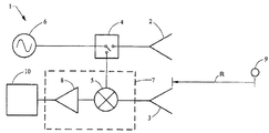
図1は、送信アンテナ2、受信アンテナ3、電力分割器4、又はミキサ5に送信信号のサンプルを提供する他の回路を有する周波数変調連続波(FMCW)レーダ1を示す。波形発生器6は、送信される信号波形を提供する。送信される信号は、対象物9で反射される。反射された信号は、受信アンテナ3で受信され、ミキサ5内で送信信号のサンプルと混合される。発生波形及び反射された信号間の差周波数は、ミキサ5により形成され、受信器7の残余部分で増幅され濾波される。受信器は、ミキサ5、及び適当なミキサ出力を選択し増幅するフィルタ及び増幅器8を有してもよい。信号プロセッサ10は、対象物に関連した所望のレーダ応答を抽出する。
FIG. 1 shows a frequency modulated continuous wave (FMCW)
図2は、線形FMCW送信信号周期中の時間関数として、送信信号11及び受信信号12の相対的関連性を示す。この線形FMCW送信は周期的に反復され、送信波形の上側周波数から下側開始周波数までの過渡に関連した時間周期を除き、送信波形及び受信波形間の差周波数は、以下の式で与えられる。
![]()
![]()
周波数変化の時間の割合、すなわちランプ(ramp)速度Kは、正の値でも負の値でもよい。ランプの持続時間TRamp及びランプ速度Kは、FMCW信号の時間・バンド幅の積を決定する。レーダのレンジ分解能は、ランプ全体の送信バンド幅の逆数であるほぼ1/TRampKである。fdは、対象物のドップラ偏移周波数である。ランプのシーケンスは同じランプ速度K及び持続時間TRampを有してもよいし、或いは、シーケンスは、使用される信号処理のタイプ及び受信信号から抽出される特定情報に依存して、ランプからランプまでの異なるK及びTRampの値を有してもよい。 The rate of time of frequency change, ie, the ramp rate K, may be positive or negative. The ramp duration T Ramp and ramp rate K determine the product of time and bandwidth of the FMCW signal. The radar range resolution is approximately 1 / T Ramp K, which is the reciprocal of the transmission bandwidth of the entire lamp. f d is the Doppler shift frequency of the object. The sequence of ramps may have the same ramp rate K and duration T Ramp , or the sequence may vary from ramp to ramp depending on the type of signal processing used and the specific information extracted from the received signal. May have different values of K and TRamp .
受信器7は、信号出力スペクトルが式(1)により与えられる周波数を有し、信号プロセッサ10への入力としての受信器信号出力を有する、当業界では公知のホモダインすなわちスーパーヘテロダインのタイプであってもよい。ランプ期間の端におけるランプ周波数の上限及び下限間の過渡に関連した周波数成分は、通常、レーダ設計用に期待された最大差周波数よりほぼ大きく、受信器7又は信号プロセッサ10での濾波により無くなる。
The
受信器7の出力信号は、要求された出力データを得るために信号プロセッサ10によって処理される。対象物及びレーダが互いに対して静止している状況では、受信器7の出力は、対象物までの距離と、式(1)の右辺の第1項に従ったレーダパラメータとの関数である周波数である。信号周波数は、スペクトルアナライザ、周波数カウンタ、高速フーリエ変換(FFT)を演算するコンピュータ等を有してもよい。レーダ及び対象物の間に相対運動がある場合、式(1)の右辺の第2項に従ったドップラ周波数偏移と、ドップラ偏移の大きさ及びレーダの使用に対する関連性に依存して、レンジ依存周波数成分からのドップラ偏移を分離する多数の手段とが、当業界で公知である。
The output signal of the
レーダの一用途は、障害物又は他の車両までの距離、接近速度、及び接近する物体の方向の決定等の、安全すなわち運転手への警告に関する自動車用途である。最小の費用で、車両用途に関連した設置の制約と両立し得る方法で、これらの機能を実行することが望ましい。FMCW波形は、この用途では2本のアンテナ、すなわち送信アンテナ及び受信アンテナを使用する構成において使用されてきた。2本のアンテナの使用により、送信波形及び受信波形間の分離が増大し、受信器の過負荷、送信ノイズの感度低下等の問題を回避する。別の構成において、信号アンテナは送受信用に使用されており、送信信号及び受信された受信器の入力の間の分離は、サーキュレータの使用によって得られる。 One application of radar is in automotive applications related to safety or driver warning, such as determining distance to obstacles or other vehicles, approach speed, and direction of approaching objects. It is desirable to perform these functions in a manner that is compatible with installation constraints associated with vehicle applications at a minimum cost. FMCW waveforms have been used in this application in configurations that use two antennas, a transmit antenna and a receive antenna. The use of two antennas increases the separation between the transmission waveform and the reception waveform, and avoids problems such as receiver overload and reduced transmission noise sensitivity. In another configuration, the signal antenna is used for transmission and reception, and the separation between the transmitted signal and the received receiver input is obtained by the use of a circulator.
しかし、いくつかの状況においては、送信信号の受信器入力からの分離が不十分になり、受信器のダイナミックレンジが、付近の物体からの戻り信号により過負荷になることを防止するには十分ではなく、或いは、サーキュレータを介して結合される送信背景ノイズが、所望の信号強度を超えるおそれがある。 However, in some situations, the separation of the transmitted signal from the receiver input is insufficient and the receiver's dynamic range is sufficient to prevent it from being overloaded with return signals from nearby objects. Alternatively, the transmission background noise coupled through the circulator may exceed the desired signal strength.
従って、自動車用及び他の用途用の改良されたレーダ提供手段が望まれている。 Accordingly, improved radar providing means for automotive and other applications are desired.
解決手段は、波形発生器、送受信スイッチ及びミキサを有するレーダであって、送受信スイッチが、送信状態及び受信状態の持続時間の合計の半分より大きい送信状態にあるレーダにより提供される。 The solution is provided by a radar having a waveform generator, a transmission / reception switch and a mixer, wherein the transmission / reception switch is in a transmission state greater than half the sum of the duration of the transmission state and the reception state.
また、解決手段は、無線周波数波形を発生する工程と、第1周期にアンテナに対して無線周波数波形を供給する工程と、第2周期の間、アンテナから信号を受信する工程と、対象物レンジを決定するために受信された信号を処理する工程とを具備し、第2周期に対する第1周期の比が1より大きい、対象物を検出する方法により提供される。 The solving means includes: generating a radio frequency waveform; supplying a radio frequency waveform to the antenna in a first period; receiving a signal from the antenna during a second period; And processing the received signal to determine, provided by a method for detecting an object wherein a ratio of a first period to a second period is greater than one.
以下、添付図面を参照して一例として本発明を説明する。 The present invention will now be described by way of example with reference to the accompanying drawings.
本発明の典型的な実施形態は図面を参照してより理解されるが、これらの実施形態は限定を意図したものではない。むしろ、本発明は、特許請求の範囲に記載された本発明の本質の範囲内である全ての変形、等価物及び変更をカバーするものである。 While exemplary embodiments of the present invention are better understood with reference to the drawings, these embodiments are not intended to be limiting. On the contrary, the invention is intended to cover all modifications, equivalents, and variations that fall within the spirit of the invention as defined by the appended claims.
ほぼ連続波形がアンテナ開口により送受信され、受信器のゲートをオンにしながら送信機のゲートをオフにすることにより、受信信号のサンプリングが得られるレーダ構成を開示する。周波数変調連続波(FMCW)、周波数偏移キーイング(FSK)、擬似ノイズ位相コード(PN)、ランダム周波数ホッピング(RFH)等の多様な波形のタイプを使用可能である。一形態において、送信信号に関連した時間周期は、受信器が戻り信号を受信できる時間に等しいか長くしてもよい。 A radar configuration is disclosed in which a substantially continuous waveform is transmitted and received through an antenna aperture and sampling of the received signal is obtained by turning off the transmitter gate while turning on the receiver gate. Various waveform types such as frequency modulated continuous wave (FMCW), frequency shift keying (FSK), pseudo noise phase code (PN), random frequency hopping (RFH) can be used. In one form, the time period associated with the transmitted signal may be equal to or longer than the time that the receiver can receive the return signal.
別の形態において、送信器及び受信器は、転送(transfer)スイッチを介して共通のアンテナ開口に接続されている。この結果、発生した信号の送信はある時間周期遮断され、発生した信号波形も、受信器ミキサへのローカル発振器入力として使用され、信号が送信されない時間の間、受信信号を復調する。或いは、送信器及び受信器は、別のアンテナに接続されるか、サーキュレータを介して共に接続されてもよい。この結果、アンテナ転送スイッチは使用されなくてもよい。別の形態において、転送スイッチは、送信周期の間、発生した波形をアンテナに、そして受信周期の間、受信器ミキサに接続するのに使用されてもよい。 In another form, the transmitter and receiver are connected to a common antenna aperture via a transfer switch. As a result, transmission of the generated signal is interrupted for a certain period of time, and the generated signal waveform is also used as a local oscillator input to the receiver mixer to demodulate the received signal during times when no signal is transmitted. Alternatively, the transmitter and receiver may be connected to another antenna or connected together via a circulator. As a result, the antenna transfer switch may not be used. In another form, the transfer switch may be used to connect the generated waveform to the antenna during the transmission period and to the receiver mixer during the reception period.
FMCW波形が使用される際、受信信号は、反射する対象物までの距離と式(1)に従った対象物の放射方向の速度の関数である周波数だけ送信信号と異なる。受信器で処理した後、発生した波形及び受信した信号波形の間の差周波数を表わす出力信号が得られる。 When an FMCW waveform is used, the received signal differs from the transmitted signal by a frequency that is a function of the distance to the reflecting object and the radial velocity of the object according to equation (1). After processing at the receiver, an output signal is obtained that represents the difference frequency between the generated waveform and the received signal waveform.
送信器がオフに切り替えられ、受信器が信号を受容するよう構成される周期に得られる受信信号のサンプルは、差周波数の値を決定するために処理することができる。交代する送信周期及び受信周期のシーケンスがFMCW波形内で規則的であるところでは、受信器出力値の時間シーケンスは、受信信号のデータサンプルであると考えてもよい。サンプリング周波数は、FMCWランプ内で生ずる信号の送信及び受信の持続時間の合計の時間の逆数で与えられる。すなわち、データサンプルは、受信周期あたり少なくとも1回得ることができる。各サンプルの持続時間は、受信時間の持続時間よりも短くてもよく、アナログ・デジタルコンバータ(ADC)の開口時間に関連してもよい。典型的には、送信周波数から受信器内で信号処理するために使用される周波数への受信信号の下方変換処理は、信号の濾波、持続時間の特性の変更を含んでもよい。サンプルはまた、受信信号の位相の瞬間的計測と考えてもよい。 Samples of the received signal obtained in the period when the transmitter is switched off and the receiver is configured to accept the signal can be processed to determine the value of the difference frequency. Where the alternating sequence of transmission and reception periods is regular in the FMCW waveform, the time sequence of receiver output values may be considered as data samples of the received signal. The sampling frequency is given by the reciprocal of the total duration of signal transmission and reception occurring within the FMCW ramp. That is, the data sample can be obtained at least once per reception period. The duration of each sample may be shorter than the duration of the reception time and may be related to the opening time of the analog to digital converter (ADC). Typically, the down conversion process of the received signal from the transmit frequency to the frequency used for signal processing in the receiver may include filtering the signal, changing the duration characteristic. Samples may also be considered as instantaneous measurements of the phase of the received signal.
ナイキスト基準(Nyquist criterion)を満足するサンプリング周波数、すなわち、例えば式(1)により与えられる受信器の出力での最大期待差周波数の2倍以上であるサンプリング周波数は、対象物までのレンジ、レーダに対する対象物の放射方向の速度、及び他のパラメータ等の特性を決定するよう処理できる受信信号スペクトルのサンプルの時間シーケンスという結果となる。適当なアンテナが使用されると、対象物への方位も得ることができる。「対象物」の用語は一般に、無線波を反射又は散乱する任意の物体を代表して使用され、対象物からの戻り信号は、レーダの受信装置により処理される信号である。対象物は、物理的状況により、自動車、壁、航空機、気象効果等であってもよい。 A sampling frequency that satisfies the Nyquist criterion, ie, a sampling frequency that is more than twice the maximum expected difference frequency at the output of the receiver given by, for example, equation (1) is The result is a time sequence of samples of the received signal spectrum that can be processed to determine characteristics such as radial velocity of the object and other parameters. If a suitable antenna is used, the orientation to the object can also be obtained. The term “object” is generally used to represent any object that reflects or scatters radio waves, and the return signal from the object is a signal that is processed by a radar receiver. The object may be a car, a wall, an aircraft, a weather effect, etc., depending on the physical situation.
FSK波形が使用されると、受信信号のサンプルは、送信信号が少なくとも2周波数の各々に存在する時間の間、少なくとも1回得られる。ランダム周波数ホッピング(RFH)波形は、任意の周波数での反復周期が長く、複数の周波数を有するFSK波形として考えてもよい。 When an FSK waveform is used, a sample of the received signal is obtained at least once during the time that the transmitted signal is present at each of at least two frequencies. A random frequency hopping (RFH) waveform may be considered as an FSK waveform having a long repetition period at an arbitrary frequency and having a plurality of frequencies.
擬似ランダム又は擬似ノイズ(PN)変調信号が使用されると、各チップの時間の間、受信信号のサンプルが少なくとも1回得られる。ここで、「チップ」とは、送信信号の位相が一定である時間である。 When a pseudo-random or pseudo-noise (PN) modulated signal is used, a sample of the received signal is obtained at least once during each chip time. Here, the “chip” is a time during which the phase of the transmission signal is constant.
一形態において、アンテナ開口は、レーダの作動が意図されている時間にわたる方位の合計と比べて放射パターン半電力ビーム幅が狭いものに対して設けてもよい。このアンテナ開口は、最大アンテナゲインの方位が信号波長の関数であるように構成される。この結果、最大アンテナゲインの方位は、単一FMCW送信の間、又はRFH波形の場合には周波数から周波数まで変化する。 In one form, antenna apertures may be provided for those with a narrow radiation pattern half power beam width compared to the sum of azimuths over the time that the radar is intended to operate. The antenna aperture is configured so that the orientation of the maximum antenna gain is a function of the signal wavelength. As a result, the orientation of the maximum antenna gain varies from frequency to frequency during a single FMCW transmission or in the case of an RFH waveform.
別の形態において、送信アンテナ及び受信アンテナは、異なってもよいし、共有開口の部分であってもよく、複数の送受信アンテナビームは、同時に又は順次形成されてもよい。 In another form, the transmit antenna and the receive antenna may be different or may be part of a shared aperture, and multiple transmit and receive antenna beams may be formed simultaneously or sequentially.
さらに別の形態において、サーキュレータは、単独又は単一経路スイッチと結合して、送信器部品及び受信器部品間の分離を提供するのに使用されてもよい。 In yet another form, the circulator may be used alone or in combination with a single path switch to provide isolation between the transmitter and receiver components.
FMCW、FSK、又はRFH波形の発生手段は、位相がロックされたループ、直接デジタルシンセサイザ(DDS)、分散フィルタ等のうちの一つであってもよい。 The FMCW, FSK, or RFH waveform generation means may be one of a phase locked loop, a direct digital synthesizer (DDS), a dispersion filter, and the like.
受信信号は、アナログ回路若しくはデジタル回路、又はその組合せにより処理することができる。この信号処理はまた、関連するメモリ及びコンピュータコードを有する1個以上のコンピュータにより実行され、数学的操作を実行し、アナログ回路又はデジタル回路により実行されるのと同等の関数を演算することができる。本明細書では、例示は本明細書では特定タイプの回路について言及しているが、各関数を実行する回路のタイプ、使用可能な回路のタイプの組合せを制限する意図はない。 The received signal can be processed by analog or digital circuits, or a combination thereof. This signal processing can also be performed by one or more computers with associated memory and computer code to perform mathematical operations and perform functions equivalent to those performed by analog or digital circuits. . As used herein, examples refer to specific types of circuits herein, but are not intended to limit the combination of the types of circuits that perform each function and the types of circuits that can be used.
コンピュータ又はデジタル回路が使用される一形態において、受信信号は、当業界で公知であるように、ADCでアナログフォーマットからデジタルフォーマットに変換されてもよい。変換処理は、アンテナによる受信後、任意の点で実行されてもよい。ADCの位置の選択は、特定の用途に依存する。 In one form in which a computer or digital circuit is used, the received signal may be converted from an analog format to a digital format by the ADC, as is known in the art. The conversion process may be executed at an arbitrary point after reception by the antenna. The selection of the ADC location depends on the particular application.
図3に示される一例において、レーダ25は、FMCW、FSK又はRFH波形であってもよい連続又はほぼ連続の波形を発生する波形発生器30と、ミキサ42、増幅器及びフィルタ47を有する受信器46と、信号プロセッサ48とを有してもよい。送信増幅器38がアンテナ36に接続されると、エネルギーが伝送され、受信器46が無効にされ(disabled)すなわち切断されるので、送信エネルギーは受信されず、受信器の過負荷すなわち感度低下を回避することができる。エネルギーが伝送されない場合、受信器46及びデジタルプロセッサ48をアクティブにし、アンテナ6の出力37に現れる信号を受信することができる。アンテナの給電点37は、受信目的のアンテナ36の出力であり、送信目的のアンテナ36の入力として使用してもよい。受信器は、例えば、スイッチ34によって受信器46及びアンテナ36間の接続を遮断することにより、スイッチ32によって波形発生器30及びミキサ入力の間の接続を遮断することにより、又はこれら双方により、或いは同様に作動する回路により、無効にすることができる。
In the example shown in FIG. 3, the
レーダ25は波形発生器30により供給される波形を増幅するよう作用する送信増幅器38を有するが、送信増幅器38は、その機能が当業界では周知であるので、他の図では明示されていない。
The
一形態において、第1転送スイッチ32は、波形発生器30の波形の出力を、ミキサ42の第1入力40に、又は図3に示されるように送信増幅器33を介して第2転送スイッチ34の2個の入力端子のうちの1個への接続点に接続する。第2転送スイッチ34の出力は、アンテナ36に印加され、送信される信号を供給する。第2転送スイッチ34の第2入力端子は、ミキサ42の第2入力44に接続される。ミキサ42の出力49は、受信器増幅器及びフィルタ47に接続される。受信器46の出力は、信号プロセッサ48に接続される。
In one form, the
レーダのこの説明は、明確化のために意図的に簡略化されており、受信器の詳細、タイミング及び同期化回路、当業界では公知であるようにレーダ機器において典型的であるこれらの関数としての同様の回路等の代表的要素は省略されている。 This description of radar has been intentionally simplified for clarity, as receiver details, timing and synchronization circuitry, these functions that are typical in radar equipment as is known in the art. Representative elements such as the same circuit are omitted.
第1転送スイッチ32及び第2転送スイッチ34が「T」で示される位置にある場合、波形発生器30の出力はアンテナ36に接続され、波形はアンテナ36により空中に放射される。信号を受信する場合、第1転送スイッチ32及び第2転送スイッチが「R」で示される位置にある。この状態では、アンテナ36がミキサ42の第2入力44に接続され、波形発生器30は、受信器46のミキサ42の第1入力44に接続される。転送スイッチ32,34の状態は「T」から「R」に周期的に変化するので、所定時間後、両スイッチは、「T」状態又は「R」状態のいずれかにある。時間の大部分で、転送スイッチ32,34は「T」状態にある。
When the
詳細には、状態遷移のシーケンスは、受信器を過負荷にしない、又は信号受信の持続時間を制限しないように、同時ではない。この結果、ミキサは、サンプリング位相検出器として作動することができる。しかし、本説明において、送信状態及び受信状態間の2個のスイッチの同時の又は瞬間的な過渡は、サンプルを表わすには十分である。さらに、受信信号の2個以上のサンプルSは、「R」状態に間に得ることができる。 Specifically, the sequence of state transitions is not simultaneous so as not to overload the receiver or limit the duration of signal reception. As a result, the mixer can operate as a sampling phase detector. However, in the present description, the simultaneous or instantaneous transients of the two switches between the transmit state and the receive state are sufficient to represent the sample. Furthermore, two or more samples S of the received signal can be obtained in the “R” state.
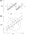
図4は、送信FMCW波形50と、レーダアンテナ位置から所定距離Dの対象物(図示せず)で反射した送信波形50に関する受信信号52とを示す。簡略化のために、単一の受信信号52が示されるが、レーダから異なる距離に複数の対象物がある場合には、複数の受信信号が現われてもよい。複数の信号が存在する場合、受信器46の出力は、複数の対象物からの戻りという結果となる周波数スペクトル含有情報を有すると考えられる。出力スペクトル内の各周波数は、レンジ分解間隔に関連した1個以上の対象物により戻されたエネルギーを表わす。レンジ分解間隔により表わされる距離は、有効信号バンド幅に依存する。FMCW波形の場合、レーダに対して放射方向の速度を有する対象物のドップラ偏移は、式(1)で表わされるように対象物までの往復遅延時間の結果生ずる発生波形と、対象物の戻り信号との間の周波数差に追加されることを理解すべきである。レンジ及びドップラ偏移成分の分離が必要な場合、当業界で公知である処理技法が使用される。
FIG. 4 shows a
転送スイッチ32,34が「R」状態にある時間では、受信信号のサンプルが得られ、この操作は図4(A)に矢印を先頭にする垂直線Sで示される。サンプル間の時間間隔は、信号処理において公知であるように、ナイキスト基準を満足する周波数で周期的である。ナイキスト周波数は、周波数スペクトルの一義的な分析が必要な最大周波数の2倍である。所望の最大周波数は、送信波形50及び受信信号52の間の差周波数48であり、レーダの最大設計レンジに対して式(1)から計算することができる。ここで、チャープ速度K、作動周波数f0、並びに対象物の放射方向の最大速度及びレンジは、具体的なシステム設計の特徴である。
During the time when the transfer switches 32 and 34 are in the “R” state, a sample of the received signal is obtained, and this operation is indicated by a vertical line S with an arrow at the top in FIG. The time interval between samples is periodic at a frequency that satisfies the Nyquist criterion, as is known in signal processing. The Nyquist frequency is twice the maximum frequency that requires a unique analysis of the frequency spectrum. The desired maximum frequency is the
ミキサ42は、波形発生器50の信号及び受信信号52の合計周波数及び差周波数の積の双方を生成する。2個の信号間の差周波数は、式(1)で与えられる。合計周波数は、受信器46内で濾波することにより無くすことができる。
The
図4(B)は図4(A)の詳細であり、FMCWランプ内での受信周期「R」に対する送信周期「T」の関係を示す。波形発生器30は、「T」が付された周期、アンテナ36に接続され、転送スイッチ32,34が送信位置にある場合、アンテナ36は送信信号を放射する。ナイキストサンプル速度で周期的に、送信器がアンテナ36から切断され、転送スイッチ32,34が「R」位置にある場合、アンテナ出力37は受信器46に接続される。対象物で反射されアンテナ36で受信された信号は、対象物に関する情報を得るために、受信器46及び信号プロセッサ48によりさらに処理される。受信間隔「R」内では、受信信号のサンプルは、送信信号がない場合に得ることができ、このことはサンプル点Sの周期的発生より図示されている。これは、サンプリングされる波形の周期の持続時間と比較して短いサンプリング時間を有するADCの作用の結果であろう。
FIG. 4B is a detail of FIG. 4A and shows the relationship of the transmission cycle “T” with respect to the reception cycle “R” in the FMCW lamp. The
「R」間隔の持続時間は、「T」間隔の持続時間よりも実質的に短い。発生信号は、スイッチ32により受信間隔「R」の間、ミキサ42のローカル発信器入力ポート40に印加してもよい。発生信号が入力ポートに印加される時間周期は、受信間隔「R」の持続時間と等しいか短い。
The duration of the “R” interval is substantially shorter than the duration of the “T” interval. The generated signal may be applied to the local
一形態において、発生信号30がミキサ42の入力ポート40に印加される時間周期は、受信間隔「R」の持続時間よりも短くてもよいので、発生信号は、図4(B)に示されるようにサンプリングパルス「S」で表わされる。この形態では、ミキサ(代表的には二重平衡ミキサ)の公知の作動に従うと、ミキサ42の出力49は、信号が入力ポート40,44の各々に現れる場合にのみえられる。このように、受信信号がサンプリングパルス「S」によりサンプリングされる時間周期は短くなり、ミキサは、アンテナ37により受信され、送受信スイッチ34によりミキサ44の入力に印加される信号のサンプリング位相検出器として作用してもよい。ミキサは、サンプリング及び保持位相検出器として作用すると考えてもよい。アナログ・デジタルコンバータサンプルは、受領時間に対して遅延してもよい。
In one form, the time period in which the generated
さらに別の形態において、「R」間隔及び「T」間隔は、ほぼ等しくなることを許容されてもよい。この場合、送受信スイッチは、送信状態及び受信状態の持続時間の合計の半分より大きい送信状態にある。送受信スイッチ32,34のスイッチング速度、コスト、感度及び他の要素の間で、トレードオフの設計がなされる。「R」間隔及び「T」間隔の比は、一設計ではほぼ等しい状態と、別の設計では「R」間隔が「T」間隔より非常に短い状態の間にある。「R」間隔の最小持続時間は、受信回路の過渡応答時間及びスイッチのスイッチング時間等の考慮によってのみ制限される。このため、「T」間隔を「R」間隔及び「T」間隔の差で割ったものとして定義される負荷時間率(duty factor)は、百分率で表わすと、50%から約100%のレンジである。自動車のレーダ用途では、例えば約95%以上の負荷時間率が使用されてもよい。
In yet another form, the “R” interval and the “T” interval may be allowed to be approximately equal. In this case, the transmission / reception switch is in a transmission state greater than half the sum of the durations of the transmission state and the reception state. A trade-off design is made between the switching speed, cost, sensitivity and other factors of the transmit / receive
受信信号は、ミキサ42、受信器46、又は信号プロセッサ48の入力でADCによりアナログからデジタルの形態に変換されてもよい。図5は、ADCの出力における信号の波形を示す。破線は、受信器が連続的に操作される環境下でのレーダの戻りを表わす周波数の連続波形を表わす。連続信号への階段状近似は、サンプル間隔でのADCによる波形の周期的サンプリングを表わす。信号の大きさは、サンプル間隔中、一定と考えてもよい。当業界で公知であるように、サンプリング周波数がナイキスト基準を満足する場合、信号波形は、一義的に表わされ分析される。
The received signal may be converted from analog to digital form by the ADC at the input of
サンプルパルスSの反復周波数はナイキスト基準を満足するように選択され、更なる信号処理は、対象物からの戻りに関連して受信信号を波形発生器30で生成された波形と混合することの結果の差周波数を一義的に決定してもよい。受信レーダ信号の相対信号強度は、対象物のレーダ断面、レーダアンテナ放射パターンに対する対象物の方位、及びレーダからのレンジを含む多数の要素に依存することが当業者には理解されよう。長いレンジでの「折り返し」対象物による曖昧さを避けるために対象物までの設計最大レンジは、各用途で異なり、問題の最大レンジが考慮される場合にのみ得られるであろうナイキスト周波数より大きなサンプリング周波数を選択する結果となる。
The repetition frequency of the sample pulse S is selected to satisfy the Nyquist criterion, and further signal processing results from mixing the received signal with the waveform generated by the
単一アンテナ開口を有するレーダ25の作動は、レーダ取付けに要する物理的面積を減らし、後述するように、適当なアンテナは、対象物のレンジと同様に、対象物の方位の決定を許容することができる。或いは、2個以上のアンテナを、送信又は受信のいずれかに使用してもよい。
The operation of
別の形態において、FMCW波形を、図6に示されるように階段状周波数波形で表わしてもよい。周波数変化の平均速度はランプ速度Kであり、サンプルSは、離散的周波数段が形成される速度と同じ速度を有するサンプル速度であってもよい。 In another form, the FMCW waveform may be represented by a stepped frequency waveform as shown in FIG. The average rate of frequency change is the ramp rate K, and the sample S may be a sample rate having the same rate as the rate at which the discrete frequency stages are formed.
レーダアンテナ基準基線方向と対象物の間の角度方向も望ましいさらに別の形態において、対象物の方位は、当業界で公知であるように、具体的なアンテナ構成に関連した多数の手段で決定することができる。これらアンテナ構成には、周波数及び時間遅延走査アレーアンテナ、台実装型皿アンテナ、モノパルス及びシーケンシャルロービングアンテナ、位相アレー等が含まれる。送信構成及び受信構成の双方において、方位の関数としてのアンテナの信号応答の変形は、自由空間放射パターンとして公知である。アンテナ効率に関連した倍数(multiplicative)要素を除き、送信用及び受信用のアンテナ放射パターンの形態は同一である。このため、説明を簡略化するために、特定の環境では一方又は他方のみを説明する。 In yet another form, where the angular orientation between the radar antenna reference baseline direction and the object is also desirable, the object orientation is determined by a number of means associated with a particular antenna configuration, as is known in the art. be able to. These antenna configurations include frequency and time delay scanning array antennas, table mount dish antennas, monopulse and sequential roving antennas, phase arrays, and the like. In both the transmit and receive configurations, the deformation of the antenna signal response as a function of orientation is known as a free space radiation pattern. Except for the multiplicative elements associated with antenna efficiency, the form of the antenna radiation pattern for transmission and reception is the same. For this reason, to simplify the description, only one or the other will be described in a particular environment.
一例において、図7に示されるように、モノパルスアンテナ構成が使用される。ここで、スイッチ位置は、送信状態「T」状態で得られるであろう位置で図示されている。モノパルスアンテナは、2個の個別放射要素36a,36bを有してもよい。各放射要素36a,36bは、ほぼ同じ放射パターンを有しており、アンテナ基線に沿って離間している。ハイブリッドカプラ37又は他の類似する装置は、波形発生器30の出力をアンテナ36a,36bに供給するので、信号は、合計放射パターンを形成するように同相で放射される。アンテナ36a,36bで受信される信号は、アンテナ36a,36bで受信された信号の合計値がΣポートに現われ、受信信号の差の値がΔポートに現れるように構成されたハイブリッドカプラ37を通って戻る。当業界で公知であるように、Σポートにおけるアンテナ出力の受信用の放射パターンは、アンテナ36a,36bの基線に対して直交する対称平面に沿った最大値を有し、Δポートにおける受信放射パターンは、同じ平面に沿って最小値を有する。Σポートに対するΔポートの位相の感知は、照準に対する信号方向を決定するのに使用することができる。角度は、Σポート及びΔポートの信号の大きさの比によって決定することができる。このタイプのモノパルスアンテナは、対象物の方位を計算するのに和アンテナ出力及び差アンテナ出力の比が使用される開ループモードで、又は、アンテナの対称平面が対象物を指すことにより、対称軸から外れた対象物に関するエラー信号が最小になるようにアンテナが方位に配置される閉ループモードすなわち追跡モードで使用することができる。閉ループモードにおいて、次に、対称平面が指す方向によって、方位が決定される。作動の開ループモード及び閉ループモードのいずれかについて、方位平面と同様に仰角平面内で計測するように、追加のアンテナを使用してもよい。
In one example, a monopulse antenna configuration is used, as shown in FIG. Here, the switch position is illustrated at the position that would be obtained in the transmission state “T” state. The monopulse antenna may have two
受信器構成は、図7に示されるように、信号が同時に処理されるように和チャンネル(s)及び差チャンネル(d)の2チャンネルを有してもよい。各チャンネルは、信号がミキサ40s,40dの入力ポートに印加されるように、波形発生器30からの波形信号が電力分割器47により電力分割されたミキサ40s,40dを有してもよい。ミキサ40s,40dの出力は受信器チャンネル46s,46dに印加され、受信器チャンネルの出力は信号プロセッサ48s,48dに印加される。信号プロセッサ48s,48dの出力は、各チャンネルにおいて各差周波数での受信信号の大きさを表わす信号であってもよい。各差周波数は、対象物までのレンジを表わす。対象物の方位は、モノパルスプロセッサ49において信号プロセッサ48s,48dの出力の比を計算し、アンテナ構成に関連した適当なスケーリング要素を適用することにより、決定することができる。図7の構造において、追加の転送スイッチ34dが存在し、ハイブリッドカプラ37のΔ出力が「R」状態のミキサ40dの入力に接続され、ハイブリッドカプラのΔ出力が「T」状態のミキサ40dの入力から切断されるように作用する。「T」状態において、スイッチ34dは、ハイブリッドかプラスチック37のΔ出力を終端抵抗に接続してもよい。
The receiver configuration may have two channels, a sum channel (s) and a difference channel (d) so that the signals are processed simultaneously, as shown in FIG. Each channel may have
別のモノパルス構造において、ハイブリッドカプラ37のΣポート及びΔポートは、連続するランプのために同じミキサ40に印加され、連続するランプのための信号プロセッサ48出力の比は、同じスペクトル周波数用に計算される。これは、シーケンシャルロービングと称される。
In another monopulse structure, the Σ and Δ ports of
対象物の方位はまた、レーダ70の放射要素として接続された周波数走査型方向アンテナ60の使用により決定できる。一例において、図8に示されるような周波数走査型アンテナは、一ランプ周期内で対象物のレンジ及び方位を決定するためにFMCW波形と共に使用することができる。図3に示されるレーダ25のアンテナ構成36は、図8に示される構成と置換してもよい。この構造において、多様なアンテナ82はアンテナ開口60を形成する。アンテナ36を除いたレーダ25は、要素70として指示される。
The orientation of the object can also be determined by the use of a frequency scanning
代表的には、アンテナは基線に沿って等しい間隔で離間するが、等しくない間隔、すなわち一表面に合致するアンテナを使用してもよい。この例において、波形発生器30が生成した信号は、伝送線80に沿って伝送され、直列のアレー状の各アンテナに結合される。連続する各アンテナ間の伝送線の長さLは、送信周波数の変化に関連する位相シフトの変化率を決定する。アレー状に連続するアンテナ間の位相シフトの差は、特定比周波数でアンテナビーム最大値が生ずる角度を決定する。このため、当業界で公知であるように、送信周波数の変化は、ビーム最大値の方位の変化という結果となる。各アンテナに印加される信号の大きさは、「一様な重み付け」として知られた同等であってもよく、又は、テーラーの立ち上がり余弦等の公知の大きさ重み付け関数に従ってもよい。一様でない重み付け関数を使用する目的は、主アンテナビーム幅の外側にあるアンテナの応答であるアンテナサイドローブの大きさを制御することである。
Typically, the antennas are spaced equally along the baseline, but unequal spacing, i.e., antennas that conform to one surface may be used. In this example, the signal generated by the
位相シフトを変更することにより、アンテナ開口の最大応答は異なる方位に向けることができ、このようなアンテナが受信する信号と同様にこのようなアンテナが送信する信号の大きさは、位相シフトの関数であり、対象物の方位に関連する。 By changing the phase shift, the maximum response of the antenna aperture can be directed in different orientations, and the magnitude of the signal transmitted by such an antenna as well as the signal received by such an antenna is a function of the phase shift. And related to the orientation of the object.
位相シフトが周波数の関数であるように位相シフトがアンテナ開口を横切る場合、最大応答の方位角は周波数の関数である。図4に示されるFMCW波形は、ランプ内で時間と共に変化する周波数を有する。従って、図8に示されるタイプのアレーアンテナは、周波数の関数である最大アンテナ方位放射パターンを有する。このようにして、レーダ信号の方位の計測は、ランプの時間限定された断片におけるランプ中に受信された信号を処理すること、各時間断片を送信周波数に関連させること、及びアンテナ放射パターンの最大応答の方位に対応させることにより、ランプの持続時間内で行うことができる。 When the phase shift traverses the antenna aperture so that the phase shift is a function of frequency, the maximum response azimuth is a function of frequency. The FMCW waveform shown in FIG. 4 has a frequency that varies with time in the lamp. Thus, an array antenna of the type shown in FIG. 8 has a maximum antenna azimuth radiation pattern that is a function of frequency. In this way, the measurement of the orientation of the radar signal can be performed by processing the signal received during the lamp in the time-limited fragment of the lamp, associating each time fragment with the transmission frequency, and the maximum of the antenna radiation pattern. By responding to the orientation of the response, this can be done within the duration of the lamp.
「方位」の用語が使用される場合、例えば受信信号の仰角を決定するために他のアンテナ構成を同等に使用することができ、これらのパラメータを同時に又は順次決定できることが当業者には理解されよう。従って、「方位」の用語は、「仰角」を含むものと理解すべきである。 Those skilled in the art will appreciate that when the term “azimuth” is used, other antenna configurations can equally be used, for example, to determine the elevation angle of the received signal, and these parameters can be determined simultaneously or sequentially. Like. Therefore, the term “azimuth” should be understood to include “elevation angle”.
図9は、FMCWランプを4個の時間間隔P1〜P4に分割した例を示す。各時間間隔Pは、最大アンテナ放射パターンの方位A1〜A4セクタにそれぞれ関連する。各時間間隔において、信号は、対象物までのレンジを決定するよう処理される。検出された対象物は、最大アンテナ放射パターンの方位Aに関連する。すなわち、ナイキスト速度で受信信号のサンプルS1群は、P1で指示された時間周期に関連すると共に、セクタA1内で方位を有する対象物に関連する。サンプルS2群は、時間周期P2に関連すると共に、セクタA2内で方位を有する対象物に関連する等である。 FIG. 9 shows an example in which the FMCW lamp is divided into four time intervals P1 to P4. Each time interval P is respectively associated with the azimuth A1-A4 sector of the maximum antenna radiation pattern. At each time interval, the signal is processed to determine the range to the object. The detected object is related to the orientation A of the maximum antenna radiation pattern. That is, the sample S1 group of received signals at the Nyquist rate is related to the object having an orientation in the sector A1 while being related to the time period indicated by P1. Sample group S2 is associated with time period P2, and with an object having an orientation within sector A2, and so on.
時間周期P1に関連するサンプルS1群は、対象物までのレンジR1を決定するように信号プロセッサ48で処理され、対象物は方位A1に関連する。方位セクタA1には異なるレンジに関連して2個以上の対象物があるが、明確化のために、図9の各方位セクタには1個の対象物のみが図示される。同様に、1個の対象物が、レンジR2内に時間周期P2に関連してあるので、方位セクタA2に関連する。
The group of samples S1 associated with the time period P1 is processed by the
方位セクタAはアンテナの特性の理想化されたものを表わし、応答関数は、各方位レンジの中心での最大値から、例えば隣接するセクタA1及びA2間の境界での代表的には電力の半分値である低い値まで変化できることを理解すべきである。方位セクタA2の中間点における方位セクタA1の実際の応答関数は、A2の応答関数よりも著しく小さい。このような訳で、方位セクタA1及びA2にけるレンジR1を表わす信号の大きさは、適当な方位セクタを決定するため、方位をより良好に見積もる等のために、比較してもよい。 The azimuth sector A represents an idealized characteristic of the antenna, and the response function is typically a half of the power at the center of each azimuth range, eg, at the boundary between adjacent sectors A1 and A2. It should be understood that the value can be changed to a lower value. The actual response function of the azimuth sector A1 at the midpoint of the azimuth sector A2 is significantly smaller than the response function of A2. For this reason, the magnitude of the signal representing the range R1 in the azimuth sectors A1 and A2 may be compared to determine an appropriate azimuth sector, to better estimate the azimuth, etc.
同様に、周波数走査型アンテナの応答関数の最大値の方向が周波数で連続的に変化するので、時間周期P内の周波数の変動は、周期P中の最大アンテナ応答の方位の変動に対応する。この変動の効果は、周期P内の信号の大きさを変調することであり、このような変調は、信号重み付けの一類型と考えることができる。 Similarly, since the direction of the maximum value of the response function of the frequency scanning antenna continuously changes with the frequency, the fluctuation of the frequency within the time period P corresponds to the fluctuation of the direction of the maximum antenna response during the period P. The effect of this variation is to modulate the magnitude of the signal within period P, and such modulation can be considered as a type of signal weighting.
別の例において、波形発生器30が発生する波形は、FSK信号であってもよい。ここで、発生した波形は第1周波数f1及び第2周波数f2のうちの一方であり、発生した波形の周波数は、第1周波数及び第2周波数の間で交代する。物理的構成は、例えば図3及び図7のいずれかであってもよい。受信信号は、波形発生器が第1周波数及び第2周波数の各々にある時間周期中に少なくとも1回、短い時間周期でサンプリングされる。第1周波数及び第2周波数の各々における送信信号及び受信信号間の位相が決定され、第1周波数で受信される信号及び第2周波数で受信される信号間の位相シフトの差が決定される。
In another example, the waveform generated by the
図10に示されるさらに別の例において、波形発生器30は単一の周波数を生成してもよく、アンテナ36を介して信号を送信するように信号発生器がアンテナに接続されると、位相変調器110が信号経路内に介在する。位相変調器110は、位相変調器を横断して信号の離散的位相シフトを与える当業界では公知の任意のタイプであってもよい。
In yet another example shown in FIG. 10, the
一形態において、位相変調器110は、シフトレジスタ112により制御されてもよい。このシフトレジスタ112は、「0」又は「1」の2進法信号の擬似ランダム(擬似ノイズとして公知の)シーケンスを生成する帰還タイプであってもよい。2進法信号を位相変調器110の入力に印加することに応答して、発生した波形の位相シフトは、基準としての入力波形に関して0°から180°まで離散的に変化してもよい。この位相シフト構造は、当業界で公知であるように位相シフトの他の増分を使用することもできるが、2進法位相シフトキーイング(BFSK)波形の一例である。擬似ランダム(PN)シーケンスを構成する2進法信号のシーケンスはシフトレジスタ112によって繰り返し生成されてもよいし、或いは、シーケンスが、計算デバイスに関連するランダムアクセスメモリ内に保存され、保存されたプログラムの実行の結果、出力してもよい。別の形態において、PNシーケンスは、コンピュータの保存プログラムを実行することにより直接計算されてもよい。
In one form, the phase modulator 110 may be controlled by the
最大限長さシーケンス等の時間を異ならせるドップラ応答関数を有する多様なPNシーケンスが公知である。 Various PN sequences having a Doppler response function with different times such as a maximum length sequence are known.
レンジ間隔にわたって一義的な対象物応答が必要なら、PNシーケンスの繰り返しの反復持続時間を、一義的な応答が望ましいレンジ間隔の少なくとも2倍に設定してもよい。波形のレンジ分解能は、公知であるように、一変調位相シフト間隔の持続時間とほぼ等しい時間間隔である。波形が0°状態又は180°状態でとられる各変調間隔は「チップ」として公知であり、このチップ持続時間は、電磁波伝搬時間として表現される波形のレンジ分解能にほぼ等しい。 If a unique object response is required over a range interval, the repetition duration of the PN sequence repetition may be set to at least twice the range interval where a unique response is desired. The range resolution of the waveform is a time interval that is approximately equal to the duration of one modulation phase shift interval, as is well known. Each modulation interval taken when the waveform is in the 0 ° state or 180 ° state is known as a “chip”, and this chip duration is approximately equal to the range resolution of the waveform expressed as electromagnetic wave propagation time.
転送スイッチ32,34は、チップあたり少なくとも1回、「T」状態から「R」状態までレーダを移行するよう作動し、図10に示されるように時間的に一連のサンプルという結果となる。この時間一連のサンプルはミキサ42の入力に印加されるので、信号は、受信器46の残余部分により処理される周波数に変換されてもよい。
Transfer switches 32 and 34 operate to shift the radar from the “T” state to the “R” state at least once per chip, resulting in a series of samples in time as shown in FIG. As this time series of samples is applied to the input of the
ミキサ42のポート40の一つに印加される波形は、波形発生器30が発生する未変調波形であり、ミキサ42の出力は、未変調波形及び受信信号サンプルの和及び差の積を有する。適当なミキサ出力は、フィルタ及び増幅器47により濾波され、増幅され、調整され、信号プロセッサ116に印加される。
The waveform applied to one of the
信号プロセッサ116は、受信器46からのデジタル化された出力を受領するか、アナログ・デジタル変換を実行する。送信されたPNシーケンスの保存された複製は、受信されたサンプル及び保存されたPNシーケンスの間の相互相関操作を実行するために使用される。当業界で公知であるように、送信されたPNシーケンスの時間遅延した複製である対象物の戻りは、保存されたPNシーケンスの開始及び受信されたPNシーケンスの間の時間差に等しい、遅延における最大値を達成するPNシーケンスとの相関係数を有する。この遅延は、対象物までのレンジの計測結果である。レーダに関する対象物の移動の効果は、対象物戻り信号にドップラ偏移を与えることであり、残りの効果は、相互相関処理内で見ることができる。
The
シフトレジスタ、FFT等を使用して、相互相関処理を実行する任意の公知の方法を使用することができる。この処理は、特殊目的のハードウエア内で、又はランダムアクセスメモリ及び保存された応用プログラムを使用するコンピュータ内で実行することができる。 Any known method of performing cross-correlation processing using a shift register, FFT, etc. can be used. This process can be performed in special purpose hardware or in a computer using random access memory and stored application programs.
チップあたり少なくとも1回の受信波形の短いサンプルを使用することにより、高い平均送信電力及び低いピーク対平均電力の比を維持しながら、単一のアンテナを使用してレーダを作動させることができる。 By using a short sample of the received waveform at least once per chip, the radar can be operated using a single antenna while maintaining a high average transmit power and a low peak-to-average power ratio.
25 レーダ
30 波形発生器
32,34 送受信スイッチ
36,60 アンテナ
42 ミキサ
47 増幅器
48 信号プロセッサ
25
Claims (22)
前記送受信スイッチが、送信状態及び受信状態の持続時間の合計の半分より大きい送信状態にあり、
前記送信状態及び前記受信状態の前記持続時間の合計の逆数でサンプリング周波数が与えられ、
前記サンプリング周波数は、前記波形発生器の出力及び受信信号の間の差周波数の2倍より大きいことを特徴とするレーダ。 A radar comprising a waveform generator, a transmission / reception switch and a mixer,
The transmit / receive switch is in a transmission state greater than half the sum of the duration of the transmission state and the reception state;
Sampling frequency is given by the reciprocal of the sum of the transmission state and the duration of the receiving state,
Radar wherein the sampling frequency is greater than twice the difference frequency between the output of the waveform generator and the received signal.
該信号増幅器は、出力応答が前記波形発生器の和周波数又は差周波数及び受信信号の一方にある周波数選択フィルタを有することを特徴とする請求項1記載のレーダ。 The radar further comprises a signal amplifier connected to the output of the mixer;
The radar according to claim 1, wherein the signal amplifier includes a frequency selective filter whose output response is one of a sum frequency or a difference frequency of the waveform generator and a received signal.
前記和パターンは、前記送信状態の間、前記波形発生器に接続されており、
前記和パターン及び前記差パターンは、前記受信状態の間、前記ミキサに接続されていることを特徴とする請求項14記載のレーダ。 The antenna assembly has at least a sum pattern and a difference pattern;
The sum pattern is connected to the waveform generator during the transmission state;
The radar according to claim 14, wherein the sum pattern and the difference pattern are connected to the mixer during the reception state.
第1周期にアンテナに対して前記無線周波数波形を供給する工程と、
第2周期の間、前記アンテナから信号を受信する工程と、
対象物レンジを決定するために受信された前記信号を処理する工程と
を具備し、
前記第2周期に対する前記第1周期の比が1より大きく、
前記第1周期及び前記第2周期の和の逆数でサンプリング周波数が与えられ、
前記サンプリング周波数は、前記受信信号及び前記無線周波数波形の間の差周波数の最大値の2倍以上であり、
前記アンテナは、和アンテナパターン及び差アンテナパターンを生成することを特徴とする、対象物の検出方法。 Generating a radio frequency waveform; and
Supplying the radio frequency waveform to the antenna in a first period;
Receiving a signal from the antenna during a second period;
Processing the received signal to determine an object range;
The ratio of the first period to the second period is greater than 1,
A sampling frequency is given by the reciprocal of the sum of the first period and the second period ;
The sampling frequency state, and are more than twice the maximum value of the difference frequency between the received signal and the radio frequency waveform,
Detection method of the antenna, characterized that you generate the sum antenna pattern and difference antenna pattern, the object.
前記アンテナ応答パターンの各々は、最大応答の異なる方位を有することを特徴とする請求項17記載の方法。 The antenna is an antenna aperture having at least two distinct antenna response patterns;
The method of claim 17, wherein each of the antenna response patterns has a different orientation of maximum response.
Applications Claiming Priority (3)
| Application Number | Priority Date | Filing Date | Title |
|---|---|---|---|
| US11/327,739 | 2006-01-05 | ||
| US11/327,739 US7791530B2 (en) | 2006-01-05 | 2006-01-05 | Time duplex apparatus and method for radar sensor front-ends |
| PCT/US2006/048942 WO2008048318A2 (en) | 2006-01-05 | 2006-12-22 | Time duplex apparatus and method for radar sensor front-ends |
Publications (3)
| Publication Number | Publication Date |
|---|---|
| JP2009522575A JP2009522575A (en) | 2009-06-11 |
| JP2009522575A5 JP2009522575A5 (en) | 2009-11-19 |
| JP5501622B2 true JP5501622B2 (en) | 2014-05-28 |
Family
ID=38223799
Family Applications (1)
| Application Number | Title | Priority Date | Filing Date |
|---|---|---|---|
| JP2008549497A Expired - Fee Related JP5501622B2 (en) | 2006-01-05 | 2006-12-22 | Time duplication device and method for radar sensor front end |
Country Status (4)
| Country | Link |
|---|---|
| US (1) | US7791530B2 (en) |
| EP (1) | EP1969392A2 (en) |
| JP (1) | JP5501622B2 (en) |
| WO (1) | WO2008048318A2 (en) |
Families Citing this family (80)
| Publication number | Priority date | Publication date | Assignee | Title |
|---|---|---|---|---|
| DE102005048209A1 (en) * | 2005-09-29 | 2007-04-05 | Valeo Schalter Und Sensoren Gmbh | Frequency modulated continuous wave radar method for motor vehicle, involves determining portion of surrounding of vehicle in time segment, and determining distances for object in another portion of surrounding in another time segment |
| US7791530B2 (en) * | 2006-01-05 | 2010-09-07 | Autoliv Asp, Inc. | Time duplex apparatus and method for radar sensor front-ends |
| FR2898732B1 (en) * | 2006-03-17 | 2008-04-25 | Thales Sa | METHOD FOR COMPENSATING ERRORS FOR POSITIONING RADIANT ELEMENTS OF A NETWORK ANTENNA |
| US7573420B2 (en) * | 2007-05-14 | 2009-08-11 | Infineon Technologies Ag | RF front-end for a radar system |
| JP4977443B2 (en) * | 2006-10-31 | 2012-07-18 | 日立オートモティブシステムズ株式会社 | Radar apparatus and radar detection method |
| US7864099B2 (en) * | 2007-07-20 | 2011-01-04 | Gm Global Technology Operations, Inc. | Low cost short range radar |
| DE102007043535A1 (en) * | 2007-09-12 | 2009-03-19 | Robert Bosch Gmbh | FMCW radar locating device and corresponding FMCW radar locating method |
| JP2009198363A (en) * | 2008-02-22 | 2009-09-03 | Omron Corp | Radiolocater and method |
| DE102008034572B4 (en) * | 2008-07-21 | 2015-04-02 | GM Global Technology Operations LLC (n. d. Ges. d. Staates Delaware) | receiving device |
| US7791528B2 (en) * | 2008-11-24 | 2010-09-07 | Autoliv Asp, Inc. | Method and apparatus for radar signal processing |
| DE102008054624A1 (en) | 2008-12-15 | 2010-06-17 | Robert Bosch Gmbh | FMCW radar sensor for motor vehicles |
| US8654006B2 (en) * | 2009-02-13 | 2014-02-18 | Freescale Semiconductor, Inc. | Integrated circuit comprising frequency generation circuitry for controlling a frequency source |
| US8447250B2 (en) * | 2009-06-09 | 2013-05-21 | Broadcom Corporation | Method and system for an integrated voltage controlled oscillator-based transmitter and on-chip power distribution network |
| JP5387191B2 (en) * | 2009-07-16 | 2014-01-15 | 富士通株式会社 | Communication device |
| GB2472085A (en) * | 2009-07-24 | 2011-01-26 | Wayne Rudd | Methods and apparatus for determining the time of receipt of a received signal |
| US20110150138A1 (en) * | 2009-12-18 | 2011-06-23 | Electronics And Telecommunications Research Institute | High linearity mixer and direct conversion receiver using the same |
| US8115672B2 (en) * | 2010-02-02 | 2012-02-14 | Thales | Method of measuring distance, notably for short-range radar |
| DE102010001761A1 (en) * | 2010-02-10 | 2011-08-11 | Robert Bosch GmbH, 70469 | radar sensor |
| FR2959318B1 (en) * | 2010-04-22 | 2013-04-05 | Eurocopter France | CONTINUOUS LOCATION OF GREAT PRECISION |
| KR101172240B1 (en) * | 2010-05-18 | 2012-08-07 | 주식회사 만도 | Sensor and alignment adjusting method |
| JP5491981B2 (en) * | 2010-06-17 | 2014-05-14 | 株式会社東芝 | Radar equipment |
| US8581778B2 (en) * | 2010-07-19 | 2013-11-12 | Scidea Research, Inc. | Pulse compression system and method |
| US8125373B2 (en) * | 2010-07-23 | 2012-02-28 | Toyota Motor Engineering & Manufacturing North America, Inc. | Microwave system utilizing elevational scanning by frequency hopping |
| US8378878B2 (en) * | 2010-08-05 | 2013-02-19 | ARETé ASSOCIATES | Creating and processing universal radar waveforms |
| KR20120065652A (en) * | 2010-12-13 | 2012-06-21 | 한국전자통신연구원 | Homodyne rf transceiver for radar sensor |
| US8207888B1 (en) * | 2011-01-24 | 2012-06-26 | The United States Of America As Represented By The Secretary Of The Navy | Systems and methods of range tracking |
| DE102012102185A1 (en) * | 2011-03-16 | 2012-09-27 | Electronics And Telecommunications Research Institute | Radar device that supports short and long range radar operation |
| JP2012194103A (en) * | 2011-03-17 | 2012-10-11 | Fujitsu Ltd | Radar device |
| KR101052025B1 (en) | 2011-04-14 | 2011-07-26 | 삼성탈레스 주식회사 | Decentralized synchronization method for multiple fmcw radar and system thereof |
| KR101213043B1 (en) * | 2011-04-19 | 2012-12-18 | 국방과학연구소 | Detecting and tracking radar, anti high speed mobile defence system having the same and tracking method of high speed mobile |
| US9935680B2 (en) | 2012-07-30 | 2018-04-03 | Photonic Systems, Inc. | Same-aperture any-frequency simultaneous transmit and receive communication system |
| US10374656B2 (en) | 2012-07-30 | 2019-08-06 | Photonic Systems, Inc. | Same-aperture any-frequency simultaneous transmit and receive communication system |
| US11539392B2 (en) | 2012-07-30 | 2022-12-27 | Photonic Systems, Inc. | Same-aperture any-frequency simultaneous transmit and receive communication system |
| US9194946B1 (en) * | 2012-09-10 | 2015-11-24 | Honeywell International Inc. | Combined FMCW and FM pulse-compression radar systems and methods |
| US9645228B1 (en) * | 2012-12-14 | 2017-05-09 | Sandia Corporation | Shaping the spectrum of random-phase radar waveforms |
| CN105073615B (en) * | 2013-03-05 | 2017-09-19 | 通力股份公司 | The gateway of elevator |
| LU92331B1 (en) * | 2013-12-10 | 2015-06-11 | Iee Sarl | Radar sensor with frequency dependent beam steering |
| US20150204969A1 (en) * | 2014-01-17 | 2015-07-23 | SpotterRF LLC | Target spotting and tracking apparatus and method |
| EP2905764B1 (en) | 2014-02-10 | 2021-04-07 | Circet | Hybrid magnetic-radar detector for space management |
| KR102204839B1 (en) * | 2014-02-11 | 2021-01-19 | 한국전자통신연구원 | Apparatus and method of detecting target using radar |
| US9389113B2 (en) * | 2014-03-05 | 2016-07-12 | Rosemount Tank Radar Ab | Low power radar level gauge system |
| JP6384018B2 (en) * | 2014-03-25 | 2018-09-05 | 日本無線株式会社 | Automotive radar equipment |
| US9864043B2 (en) * | 2014-07-23 | 2018-01-09 | Honeywell International Inc. | FMCW radar with phase encoded data channel |
| US9791550B2 (en) | 2014-07-23 | 2017-10-17 | Honeywell International Inc. | Frequency-Modulated-Continuous-Wave (FMCW) radar with timing synchronization |
| CN105301592B (en) * | 2015-10-12 | 2017-09-29 | 合肥工业大学 | Using the multi-targets recognition algorithm of automobile anti-collision radar system |
| DE102015226443A1 (en) * | 2015-12-22 | 2017-06-22 | Robert Bosch Gmbh | Radar sensor, corresponding operating method and vehicle |
| DE102016202936A1 (en) * | 2016-02-25 | 2017-08-31 | Robert Bosch Gmbh | Device for determining operating data for a radar sensor |
| EP3211445B1 (en) * | 2016-02-29 | 2019-06-12 | Nxp B.V. | Radar system |
| EP3211444B1 (en) | 2016-02-29 | 2019-06-12 | Nxp B.V. | Radar system |
| WO2017175190A1 (en) | 2016-04-07 | 2017-10-12 | Uhnder, Inc. | Adaptive transmission and interference cancellation for mimo radar |
| US10261179B2 (en) | 2016-04-07 | 2019-04-16 | Uhnder, Inc. | Software defined automotive radar |
| US9846228B2 (en) | 2016-04-07 | 2017-12-19 | Uhnder, Inc. | Software defined automotive radar systems |
| US11002829B2 (en) * | 2016-04-15 | 2021-05-11 | Mediatek Inc. | Radar interference mitigation method and apparatus |
| US10573959B2 (en) | 2016-04-25 | 2020-02-25 | Uhnder, Inc. | Vehicle radar system using shaped antenna patterns |
| WO2017187278A1 (en) | 2016-04-25 | 2017-11-02 | Uhnder, Inc. | Pmcw – pmcw interference mitigation |
| US9575160B1 (en) | 2016-04-25 | 2017-02-21 | Uhnder, Inc. | Vehicular radar sensing system utilizing high rate true random number generator |
| US9806914B1 (en) | 2016-04-25 | 2017-10-31 | Uhnder, Inc. | Successive signal interference mitigation |
| US9791551B1 (en) | 2016-04-25 | 2017-10-17 | Uhnder, Inc. | Vehicular radar system with self-interference cancellation |
| WO2017187331A1 (en) | 2016-04-25 | 2017-11-02 | Uhnder, Inc. | Vehicle radar system with a shared radar and communication system |
| WO2017187304A2 (en) | 2016-04-25 | 2017-11-02 | Uhnder, Inc. | Digital frequency modulated continuous wave radar using handcrafted constant envelope modulation |
| US9599702B1 (en) | 2016-04-25 | 2017-03-21 | Uhnder, Inc. | On-demand multi-scan micro doppler for vehicle |
| US9791564B1 (en) | 2016-04-25 | 2017-10-17 | Uhnder, Inc. | Adaptive filtering for FMCW interference mitigation in PMCW radar systems |
| US9753121B1 (en) | 2016-06-20 | 2017-09-05 | Uhnder, Inc. | Power control for improved near-far performance of radar systems |
| US10620298B2 (en) * | 2016-08-26 | 2020-04-14 | Infineon Technologies Ag | Receive chain configuration for concurrent multi-mode radar operation |
| US9869762B1 (en) | 2016-09-16 | 2018-01-16 | Uhnder, Inc. | Virtual radar configuration for 2D array |
| DE102017200706A1 (en) * | 2017-01-18 | 2018-07-19 | Robert Bosch Gmbh | Multiple subsampled chirp sequence radar |
| US11454697B2 (en) | 2017-02-10 | 2022-09-27 | Uhnder, Inc. | Increasing performance of a receive pipeline of a radar with memory optimization |
| WO2018146530A1 (en) | 2017-02-10 | 2018-08-16 | Uhnder, Inc. | Reduced complexity fft-based correlation for automotive radar |
| WO2018146634A1 (en) | 2017-02-10 | 2018-08-16 | Uhnder, Inc. | Increasing performance of a receive pipeline of a radar with memory optimization |
| JP6717254B2 (en) * | 2017-04-19 | 2020-07-01 | 株式会社デンソー | Radar signal processor and radar system |
| US11105890B2 (en) | 2017-12-14 | 2021-08-31 | Uhnder, Inc. | Frequency modulated signal cancellation in variable power mode for radar applications |
| KR102093363B1 (en) * | 2018-04-12 | 2020-03-25 | 주식회사 만도 | Radar system and Transmit Apparatus therefor |
| US11474225B2 (en) | 2018-11-09 | 2022-10-18 | Uhnder, Inc. | Pulse digital mimo radar system |
| WO2020183392A1 (en) | 2019-03-12 | 2020-09-17 | Uhnder, Inc. | Method and apparatus for mitigation of low frequency noise in radar systems |
| US11309636B2 (en) * | 2019-12-18 | 2022-04-19 | Waymo Llc | Antenna structure for reducing beam squint and sidelobes |
| WO2021144711A2 (en) | 2020-01-13 | 2021-07-22 | Uhnder, Inc. | Method and system for intefrence management for digital radars |
| DE102020202500A1 (en) * | 2020-02-27 | 2021-09-02 | Robert Bosch Gesellschaft mit beschränkter Haftung | MIMO radar system |
| DE102020202498A1 (en) * | 2020-02-27 | 2021-09-02 | Robert Bosch Gmbh | MIMO radar system |
| US20230094118A1 (en) * | 2021-09-27 | 2023-03-30 | Texas Instruments Incorporated | Radar system implementing segmented chirps and phase compensation for object movement |
| WO2023068970A1 (en) * | 2021-10-19 | 2023-04-27 | Ольга Викторовна КОШУРИНОВА | Transceiving device for a homodyne radar |
Family Cites Families (22)
| Publication number | Priority date | Publication date | Assignee | Title |
|---|---|---|---|---|
| US3087153A (en) * | 1956-06-08 | 1963-04-23 | Bendix Corp | Gated pulse radar system |
| US3370166A (en) * | 1966-02-21 | 1968-02-20 | Bosch Arma Corp | Object detector and control system employing same |
| US3991418A (en) * | 1970-02-10 | 1976-11-09 | Avco Corporation | Electromagnetic wave direction finding using Doppler techniques |
| US4161732A (en) * | 1976-11-12 | 1979-07-17 | Westinghouse Electric Corp. | Gated pulse compression radar |
| US4219812A (en) * | 1978-12-26 | 1980-08-26 | The United States Of America As Represented By The Secretary Of The Army | Range-gated pulse doppler radar system |
| US4952939A (en) * | 1989-02-16 | 1990-08-28 | Seed Willian R | Radar intrusion detection system |
| US5309160A (en) * | 1993-01-04 | 1994-05-03 | Westinghouse Electric Corp. | Radar system and method having variable tracking range |
| US5636123A (en) * | 1994-07-15 | 1997-06-03 | Rich; Richard S. | Traffic alert and collision avoidance coding system |
| EP0777131A1 (en) * | 1995-12-06 | 1997-06-04 | Geberit Technik Ag | Surveillance device with a radar probe |
| US5726657A (en) * | 1996-03-22 | 1998-03-10 | Lockheed Martin Corporation | Phase coherent radar system using fast frequency agile waveform synthesis |
| FR2763134B1 (en) * | 1997-05-07 | 1999-07-30 | Thomson Csf | METHOD FOR PROCESSING THE RECEIVING SIGNAL OF A SAR RADAR WITH FREQUENCY RAMPES |
| JP3011164B2 (en) | 1997-11-14 | 2000-02-21 | 日本電気株式会社 | Radar equipment |
| US6020843A (en) * | 1999-03-30 | 2000-02-01 | Raytheon Company | Technique for implementing very large pulse compression biphase codes |
| JP4258941B2 (en) * | 1999-06-03 | 2009-04-30 | 株式会社デンソー | Radar equipment |
| JP2001051049A (en) * | 1999-08-10 | 2001-02-23 | Oki Electric Ind Co Ltd | Radar |
| JP2002122661A (en) * | 2000-10-12 | 2002-04-26 | Fujitsu Ten Ltd | Fm-cw radar of 1 antenna time sharing control system |
| JP2002168946A (en) * | 2000-11-30 | 2002-06-14 | Matsushita Electric Works Ltd | Range-finding radar system |
| FI110966B (en) | 2001-11-21 | 2003-04-30 | Vaisala Oyj | A method for processing a Frequency Modulated Interrupt Continuous Wave Radar (FMICW) signal |
| JP4266674B2 (en) * | 2003-03-05 | 2009-05-20 | 富士通テン株式会社 | Radar equipment |
| JP4103675B2 (en) * | 2003-05-07 | 2008-06-18 | 三菱電機株式会社 | Radar equipment |
| WO2005069037A1 (en) * | 2004-01-15 | 2005-07-28 | Fujitsu Ten Limited | Radar |
| US7791530B2 (en) * | 2006-01-05 | 2010-09-07 | Autoliv Asp, Inc. | Time duplex apparatus and method for radar sensor front-ends |
-
2006
- 2006-01-05 US US11/327,739 patent/US7791530B2/en active Active
- 2006-12-22 EP EP06851798A patent/EP1969392A2/en not_active Ceased
- 2006-12-22 JP JP2008549497A patent/JP5501622B2/en not_active Expired - Fee Related
- 2006-12-22 WO PCT/US2006/048942 patent/WO2008048318A2/en active Application Filing
Also Published As
| Publication number | Publication date |
|---|---|
| JP2009522575A (en) | 2009-06-11 |
| WO2008048318A2 (en) | 2008-04-24 |
| US20070152871A1 (en) | 2007-07-05 |
| WO2008048318A3 (en) | 2008-07-10 |
| US7791530B2 (en) | 2010-09-07 |
| EP1969392A2 (en) | 2008-09-17 |
Similar Documents
| Publication | Publication Date | Title |
|---|---|---|
| JP5501622B2 (en) | Time duplication device and method for radar sensor front end | |
| US11740323B2 (en) | Power control for improved near-far performance of radar systems | |
| US11906618B2 (en) | MIMO radar apparatuses and MIMO radar methods | |
| US9470784B2 (en) | Radar device | |
| AU2002333123B2 (en) | Spread spectrum radar with leak compensation at baseband | |
| US10557933B2 (en) | Radar device and position-determination method | |
| US10436890B2 (en) | Method for finding the position of objects using an FMCW radar | |
| US8947293B2 (en) | Radar apparatus | |
| US11422249B2 (en) | Radar device and method for detecting radar targets | |
| US20080088499A1 (en) | Methods and apparatus for hyperview automotive radar | |
| US10768276B2 (en) | Decentralised radar system | |
| AU2002333123A1 (en) | Spread spectrum radar with leak compensation at baseband | |
| JPH04220582A (en) | Poly-static correlation radar | |
| US20210364599A1 (en) | Radar receiving system and method for compensating a phase error between radar receiving circuits | |
| US20220066012A1 (en) | Multiple-mode radar with resolution of spatial ambiguity | |
| JP2021513657A (en) | Angle-resolved, wideband radar sensor for automobiles | |
| US8779968B2 (en) | System and method for microwave ranging to a target in presence of clutter and multi-path effects | |
| US7961139B2 (en) | Digital beam forming using frequency-modulated signals | |
| JP2016151424A (en) | Radar system | |
| US20210215820A1 (en) | Method and system for intefrence management for digital radars | |
| US20220334218A1 (en) | End-of line phase calibration of radar devices | |
| US11681039B2 (en) | Failure determination apparatus and method of vehicle radar apparatus, and vehicle radar apparatus with the same | |
| Jain et al. | Radar fundamentals | |
| KR20160066413A (en) | Operating method of FMCW radar | |
| US20230305103A1 (en) | Mimo radar apparatus and mimo radar method |
Legal Events
| Date | Code | Title | Description |
|---|---|---|---|
| A521 | Written amendment |
Free format text: JAPANESE INTERMEDIATE CODE: A523 Effective date: 20090928 |
|
| A621 | Written request for application examination |
Free format text: JAPANESE INTERMEDIATE CODE: A621 Effective date: 20090928 |
|
| A131 | Notification of reasons for refusal |
Free format text: JAPANESE INTERMEDIATE CODE: A131 Effective date: 20120207 |
|
| A521 | Written amendment |
Free format text: JAPANESE INTERMEDIATE CODE: A523 Effective date: 20120502 |
|
| A131 | Notification of reasons for refusal |
Free format text: JAPANESE INTERMEDIATE CODE: A131 Effective date: 20121225 |
|
| A601 | Written request for extension of time |
Free format text: JAPANESE INTERMEDIATE CODE: A601 Effective date: 20130322 |
|
| A602 | Written permission of extension of time |
Free format text: JAPANESE INTERMEDIATE CODE: A602 Effective date: 20130329 |
|
| A601 | Written request for extension of time |
Free format text: JAPANESE INTERMEDIATE CODE: A601 Effective date: 20130423 |
|
| A602 | Written permission of extension of time |
Free format text: JAPANESE INTERMEDIATE CODE: A602 Effective date: 20130501 |
|
| A601 | Written request for extension of time |
Free format text: JAPANESE INTERMEDIATE CODE: A601 Effective date: 20130523 |
|
| A602 | Written permission of extension of time |
Free format text: JAPANESE INTERMEDIATE CODE: A602 Effective date: 20130530 |
|
| A521 | Written amendment |
Free format text: JAPANESE INTERMEDIATE CODE: A523 Effective date: 20130621 |
|
| TRDD | Decision of grant or rejection written | ||
| A01 | Written decision to grant a patent or to grant a registration (utility model) |
Free format text: JAPANESE INTERMEDIATE CODE: A01 Effective date: 20140311 |
|
| A61 | First payment of annual fees (during grant procedure) |
Free format text: JAPANESE INTERMEDIATE CODE: A61 Effective date: 20140312 |
|
| R150 | Certificate of patent or registration of utility model |
Ref document number: 5501622 Country of ref document: JP Free format text: JAPANESE INTERMEDIATE CODE: R150 |
|
| R250 | Receipt of annual fees |
Free format text: JAPANESE INTERMEDIATE CODE: R250 |
|
| R250 | Receipt of annual fees |
Free format text: JAPANESE INTERMEDIATE CODE: R250 |
|
| S111 | Request for change of ownership or part of ownership |
Free format text: JAPANESE INTERMEDIATE CODE: R313113 |
|
| R371 | Transfer withdrawn |
Free format text: JAPANESE INTERMEDIATE CODE: R371 |
|
| S111 | Request for change of ownership or part of ownership |
Free format text: JAPANESE INTERMEDIATE CODE: R313113 |
|
| R350 | Written notification of registration of transfer |
Free format text: JAPANESE INTERMEDIATE CODE: R350 |
|
| R250 | Receipt of annual fees |
Free format text: JAPANESE INTERMEDIATE CODE: R250 |
|
| R250 | Receipt of annual fees |
Free format text: JAPANESE INTERMEDIATE CODE: R250 |
|
| LAPS | Cancellation because of no payment of annual fees |