JP5465043B2 - Adhesive tape sticking device and sticking method - Google Patents
Adhesive tape sticking device and sticking method Download PDFInfo
- Publication number
- JP5465043B2 JP5465043B2 JP2010046913A JP2010046913A JP5465043B2 JP 5465043 B2 JP5465043 B2 JP 5465043B2 JP 2010046913 A JP2010046913 A JP 2010046913A JP 2010046913 A JP2010046913 A JP 2010046913A JP 5465043 B2 JP5465043 B2 JP 5465043B2
- Authority
- JP
- Japan
- Prior art keywords
- chuck
- release tape
- adhesive tape
- tape
- pair
- Prior art date
- Legal status (The legal status is an assumption and is not a legal conclusion. Google has not performed a legal analysis and makes no representation as to the accuracy of the status listed.)
- Active
Links
Images


Landscapes
- Electric Connection Of Electric Components To Printed Circuits (AREA)
- Supply And Installment Of Electrical Components (AREA)
- Wire Bonding (AREA)
- Adhesive Tape Dispensing Devices (AREA)
Description
この発明は離型テープに貼着された粘着テープを所定長さに切断して電子部品に貼着する粘着テープの貼着装置及び貼着方法に関する。 The present invention relates to an adhesive tape attaching apparatus and an attaching method for cutting an adhesive tape attached to a release tape to a predetermined length and attaching the adhesive tape to an electronic component.
たとえば、液晶表示装置を製造する場合、基板としての液晶表示装置のパネルに、電子部品としてのTCPを実装するための実装装置が用いられる。上記TCPは金型によってキヤリアテープから打ち抜かれた後、所定角度ずつ間欠的に回転駆動されるインデックステーブルに供給される。このインデックステーブルには1回当たりの回転角度に応じた間隔で周方向に複数の吸着ヘッドが設けられている。そして、上記金型によって打ち抜かれたTCPは複数の吸着ヘッドに順次供給される。 For example, when manufacturing a liquid crystal display device, a mounting device for mounting TCP as an electronic component on a panel of the liquid crystal display device as a substrate is used. The TCP is punched from the carrier tape by a mold and then supplied to an index table that is rotationally driven by a predetermined angle. The index table is provided with a plurality of suction heads in the circumferential direction at intervals corresponding to the rotation angle per time. The TCP punched out by the mold is sequentially supplied to a plurality of suction heads.
上記パネルはXYテーブルに位置決め載置されていて、このXYテーブルによってXY方向に駆動されるようになっている。上記インデックステーブルの実装ポジションにおいて、上記TCPに設けられた位置合わせマークと、上記パネルに設けられた位置合わせマークとが撮像カメラによって撮像され、その撮像信号が画像処理部で処理される。そして、画像処理部での上記撮像信号の処理に基いて、上記TCPの位置合わせマークに上記パネルの位置合わせマークが一致するよう、上記XYテーブルの駆動が制御されて上記パネルが位置決めされるようになっている。 The panel is positioned and placed on an XY table, and is driven in the XY direction by the XY table. At the mounting position of the index table, the alignment mark provided on the TCP and the alignment mark provided on the panel are imaged by the imaging camera, and the imaging signal is processed by the image processing unit. Then, based on the processing of the imaging signal in the image processing unit, the driving of the XY table is controlled so that the panel alignment mark is aligned with the TCP alignment mark so that the panel is positioned. It has become.
上記TCPに対して上記パネルが位置決めされると、TCPを保持した吸着ヘッドが下降方向に駆動され、そのTCPを上記パネルに設けられた異方性導電部材からなる粘着テープに加圧して貼着、つまり実装するようになっている。インデックステーブルを用いて基板にTCPを実装する従来の実装装置は、たとえば特許文献1に開示されている。
When the panel is positioned with respect to the TCP, the suction head holding the TCP is driven in the downward direction, and the TCP is applied to an adhesive tape made of an anisotropic conductive member provided on the panel. In other words, it is designed to be implemented. A conventional mounting apparatus that mounts TCP on a substrate using an index table is disclosed in, for example,
ところで、特許文献1に開示された実装装置においては、基板にTCPを実装するための粘着テープを、上記基板の一側の長手方向全長にわたって貼着し、そこに上記TCPを所定間隔で実装するようにしている。
By the way, in the mounting apparatus disclosed in
そのため、粘着テープの、所定間隔で貼着されたTCPの間に位置する部分は、TCPの実装に必要のない部分となるから、その部分が無駄になり、コスト上昇につながるということがある。 For this reason, the portion of the adhesive tape located between the TCPs attached at a predetermined interval becomes a portion that is not necessary for mounting the TCP, so that the portion is wasted, leading to an increase in cost.
そこで、最近では基板に粘着テープを貼着せず、TCPに、このTCPの幅寸法に対応する長さに切断された粘着テープを貼着することで、粘着テープの無駄をなくすということが考えられている。このような先行技術は特許文献2に示されている。
Therefore, recently, it is considered that the adhesive tape is not attached to the substrate, and the adhesive tape cut to a length corresponding to the width dimension of the TCP is attached to the TCP, thereby eliminating the waste of the adhesive tape. ing. Such prior art is disclosed in
特許文献2では、離型テープに貼着された粘着テープをTCPの幅寸法に対応する長さで切断し、その粘着テープを上にしてインデックステーブルの吸着ヘッドに保持された電子部品に対向するよう位置決めする。
In
ついで、上記粘着テープを離型テープとともに押し上げ、インデックステーブルの吸着ヘッドに保持されたTCPに貼着した後、その粘着テープの下面から離型テープを剥離する。そして、TCPは粘着テープの離型テープが剥離された面を基板に貼着することで実装される。 Next, the adhesive tape is pushed up together with the release tape and attached to the TCP held by the suction head of the index table, and then the release tape is peeled off from the lower surface of the adhesive tape. And TCP is mounted by sticking the surface by which the release tape of the adhesive tape was peeled off to a board | substrate.
TCPを基板に実装したならば、インデックステーブルを所定角度回転させるとともに、上記離型テープを所定長さでピッチ送りする。そして、所定長さに切断された新たな粘着テープをインデックステーブルの吸着ヘッドに保持されたTCPに対向させ、その粘着テープをTCPに貼着した後、そのTCPを基板に実装するということが繰り返して行なわれる。 When the TCP is mounted on the substrate, the index table is rotated by a predetermined angle, and the release tape is pitch-fed by a predetermined length. Then, the new adhesive tape cut to a predetermined length is opposed to the TCP held by the suction head of the index table, the adhesive tape is attached to the TCP, and then the TCP is mounted on the substrate repeatedly. It is done.
特許文献2では、上記粘着テープが貼着された離型テープは供給リールから繰り出され、巻き取りリールに巻き取られるようになっている。したがって、上記供給リールによる離型テープの巻き取り長さを設定することで、所定長さに切断された新たな粘着テープを吸着ヘッドに保持されたTCPに順次対向位置決めすることができる。
In
ところで、技術文献2では、上述したように離型テープを巻き取りリールで巻き取って所定長さに切断された新たな粘着テープを吸着ヘッドに保持されたTCPに対して位置決めする構成であるから、巻き取りリールには粘着テープが除去された離型テープが巻き取られることになる。
By the way, in the
そのため、巻き取りリールを繰り返して使用する際、この巻き取りリールに巻き取られた離型テープを除去して廃棄しなければならないから、その作業に手間が掛かるということがある。 For this reason, when the take-up reel is used repeatedly, the release tape wound on the take-up reel must be removed and discarded, which may take time.
そこで、離型テープの送りを巻き取りリールに換えて固定チャックと引き出しチャックとで行なうことが考えられている。すなわち、待機位置状態では固定チャックの上方に引き出しチャックが位置決めされている。 Therefore, it is considered that the release tape is fed by a fixed chuck and a drawer chuck instead of the take-up reel. That is, in the standby position state, the drawer chuck is positioned above the fixed chuck.
そして、引き出しチャックによって離型テープを挟持したならば、固定チャックを開放して、上記引き出しチャックを下降させる。それによって、離型テープを所定の長さ引き出したならば、その引出し状態で固定チャックによって離型テープを挟持固定して離型テープが弛むのを防止する。 When the release tape is clamped by the drawer chuck, the fixed chuck is opened and the drawer chuck is lowered. Accordingly, when the release tape is pulled out by a predetermined length, the release tape is clamped and fixed by the fixing chuck in the pulled-out state to prevent the release tape from loosening.
ついで、上記引き出しチャックを開いて待機位置まで上昇させてから、この引き出しチャックを閉じて上記離型テープを挟持させた後、固定チャックによる離型テープの挟持状態を開放して上記引き出しチャックを下降させるという動作を繰り返すことで、上記離型テープを所定長さづつピッチ送りする。それによって、離型テープの粘着テープがTCPに貼着されて除去された部分を落下させて回収容器に集積するようにしている。 Next, the drawer chuck is opened and raised to a standby position, and then the drawer chuck is closed and the release tape is clamped, and then the release tape is clamped by the fixed chuck and the drawer chuck is lowered. By repeating this operation, the release tape is pitch-fed by a predetermined length. As a result, the part of the release tape that has been removed by sticking to the TCP is dropped and collected in the collection container.
このようにすれば、巻き取りリールを用いる場合に比べて粘着テープが貼着除去された離型テープの処理が容器となるから、生産性の向上を図ることができるという利点を有する。 In this way, compared to the case where a take-up reel is used, the processing of the release tape from which the adhesive tape has been adhered and removed becomes a container, and thus there is an advantage that productivity can be improved.
ところで、粘着テープは、離型テープに貼着された状態で、カッタによって所定長さに切断される。粘着テープは粘着性の樹脂によって形成されている。そのため、粘着テープをカッタによって切断すると、所定長さに切断された粘着テープをTCPに貼着することで除去した後であっても、粘着テープの一部、とくにカッタによって押圧切断された部分が離型テープに付着残留するということがある。 By the way, the adhesive tape is cut into a predetermined length by a cutter in a state of being attached to the release tape. The adhesive tape is made of an adhesive resin. Therefore, when the adhesive tape is cut by the cutter, even after the adhesive tape cut to a predetermined length is removed by sticking to the TCP, a part of the adhesive tape, in particular, the part that is pressed and cut by the cutter Sometimes it remains attached to the release tape.
そのような状態で、上述したように固定チャックと引き出しチャックの開閉及び引き出しチャックの上下動を制御して離型テープをピッチ送りすると、固定チャックを開いて引き出しチャックによって離型テープを挟持してピッチ送りする際、離型テープに付着残留した粘着テープの一部によって離型テープが固定チャックに付着することがあるから、固定チャックを開放しても、離型テープが自重によって下方へ落下しなくなってしまうということがある。 In such a state, as described above, the opening and closing of the fixed chuck and the drawer chuck and the vertical movement of the drawer chuck are controlled to pitch-feed the release tape, and then the fixed chuck is opened and the release tape is clamped by the drawer chuck. When the pitch is fed, the release tape may adhere to the fixed chuck due to a part of the adhesive tape remaining on the release tape. Even if the fixed chuck is released, the release tape falls down due to its own weight. Sometimes it disappears.
そのため、離型テープが固定チャックに貼着した状態で、上述したように引き出しチャックを上下動させて離型テープのピッチ送りを繰り返して行なうと、固定チャックに付着した離型テープが引き出しチャックや固定チャックに絡まって離型テープのピッチ送りができなくなるということが生じる。 Therefore, when the release tape is stuck to the fixed chuck and the drawer chuck is moved up and down as described above and the pitch of the release tape is repeated, the release tape attached to the fixed chuck is removed from the drawer chuck and It may happen that the pitch of the release tape becomes entangled with the fixed chuck.
この発明は、固定チャックと引き出しチャックとで離型テープを所定長さづつ送る場合、離型テープが固定チャックに付着しても、引き出しチャックや固定チャックに絡まることがないようにした粘着テープの貼着装置及び貼着方法を提供することにある。 According to the present invention, when a release tape is fed by a fixed length between a fixed chuck and a drawer chuck, even if the release tape adheres to the fixed chuck, the adhesive tape is designed not to be entangled with the drawer chuck or the fixed chuck. It is providing the sticking apparatus and the sticking method.
この発明は、離型テープに貼着された粘着テープを電子部品へ貼着する貼着装置であって、
上記粘着テープを電子部品に貼着する貼着手段と、
上記離型テープを所定ピッチで間欠的に送る送り手段と、
を具備し、
上記送り手段は、上記離型テープを挟持する一対の挟持片を開閉駆動する固定チャックと、上記離型テープを挟持する一対の挟持片を開閉駆動及び上記離型テープの送り方向に移動駆動する引き出しチャックを有し、上記固定チャックの一対の挟持片が、上記離型テープを一対の挟持片を閉じて挟持する上記引き出しチャックの挟持片が通過できる間隔まで開放し、上記引き出しチャックの一対の挟持片が、所定ピッチ送られた上記離型テープを一対の挟持片を閉じて挟持する上記固定チャックの挟持片が通過できる間隔まで開放可能なように構成されていることを特徴とする粘着テープの貼着装置にある。
This invention is an attaching device for attaching an adhesive tape attached to a release tape to an electronic component ,
An adhering means for adhering the adhesive tape to an electronic component;
A feeding means for intermittently feeding the release tape at a predetermined pitch ;
Comprising
Said feeding means includes a fixing chuck for opening and closing the pair of holding pieces for holding the above release tape, which movement driving the pair of holding pieces for holding the above release tape feeding direction of the opening and closing and the release tape A pair of clamping pieces of the fixed chuck, and a pair of clamping pieces of the stationary chuck are opened up to an interval through which the clamping piece of the drawer chuck that clamps the release tape by closing the pair of clamping pieces can pass; The pressure-sensitive adhesive tape is characterized in that the holding piece is configured to be able to be opened to an interval at which the holding piece of the fixed chuck that holds the release tape fed at a predetermined pitch can be passed by closing a pair of holding pieces. In the pasting device.
この発明によれば、固定チャックを開いて引き出しチャックを下降させて離型テープをピッチ送りするとき、固定チャックに付着した離型テープは引き出しチャックの動きによって固定チャックから剥離されるから、離型テープを引き出しチャックに絡ませることなく確実に送ることが可能となる。 According to this invention, when the fixed chuck is opened and the drawer chuck is lowered to pitch-feed the release tape, the release tape attached to the fixed chuck is peeled off from the fixed chuck by the movement of the drawer chuck. The tape can be reliably fed without being pulled out and entangled with the chuck.
以下、この発明の実施の形態を図面を参照しながら説明する。 Embodiments of the present invention will be described below with reference to the drawings.
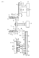
図1乃至図6はこの発明の第1の実施の形態を示し、図1は実装装置の全体構成の概略図である。この実装装置は基板としてのたとえば液晶表示装置用のパネル1を搬送する第1の搬送手段であるパネルテーブル2と、電子部品としてのTCP3を搬送する第2の搬送手段としてのインデックステーブル4を有する。
1 to 6 show a first embodiment of the present invention, and FIG. 1 is a schematic diagram of the overall configuration of a mounting apparatus. This mounting apparatus has a panel table 2 which is a first transport means for transporting, for example, a
上記パネルテーブル2は、ベース5上にX方向(図1の紙面に直交する方向)に沿って移動可能に設けられたXテーブル6を有する。このXテーブル6は上記ベース5に設けられたX駆動源7によって上記ベース5上をX方向に沿って駆動されるようになっている。
The panel table 2 has an X table 6 provided on a
上記Xテーブル6にはX方向と直交するY方向(矢印で示す)に沿って移動可能なYテーブル8が設けられている。このYテーブル8は上記Xテーブル6に設けられたY駆動源9によってY方向に沿って駆動されるようになっている。上記Yテーブル8にはθテーブル10が回転方向に移動可能に設けられ、上記Yテーブル8に設けられたθ駆動源10aによって回転方向に駆動されるようになっている。
The X table 6 is provided with a Y table 8 movable along a Y direction (indicated by an arrow) orthogonal to the X direction. The Y table 8 is driven along the Y direction by a
そして、このθテーブル10の上面に上記パネル1が供給され、たとえば真空吸着などの手段によって移動不能に保持される。それによって、上記パネル1は上記パネルテーブル2によってXY及びθ方向に対して位置決め可能となっている。なお、θテーブル10はパネル1よりも小さく形成されている。それによって、パネル1は周辺部をθテーブル10の周辺部から外方へ突出させている。
And the said
上記インデックステーブル4は、中心に回転軸11が設けられ、この回転軸11はθ駆動源12によって図2に矢印Rで示す時計方向に所定角度ずつ間欠的に回転駆動されるようになっている。この実施の形態では、上記インデックステーブル4は90度の回転角度で間欠駆動されるようになっている。
The index table 4 is provided with a
上記インデックステーブル4の上面には、90度間隔で4つの支持体13が設けられている。図1では2つの支持体13だけを図示し、他の支持体13を省略している。この支持体13は側面形状がL字状をなしていて、その垂直面には可動体14がリニアガイド15によって垂直方向に移動可能に支持されている。
Four supports 13 are provided on the upper surface of the index table 4 at intervals of 90 degrees. In FIG. 1, only two
図1に示すように、上記支持体13の上端にはブラケット16が設けられ、このブラケット16には実装シリンダ17が軸線を垂直にし、かつロッド17aの先端を上記可動体14の上端に連結して設けられている。なお、図2においては上記実装シリンダ17の図示を省略している。
As shown in FIG. 1, a
各可動体14の下端面には実装手段として側面形状がL字状の吸着ヘッド18が設けられている。この吸着ヘッド18は、図2にAで示す受け取りポジションで図示しない部品供給部から供給されたTCP3を吸着保持し、上記パネル1に実装するようになっている。なお、インデックステーブル4は上述した受け取りポジションAの他に、B〜Dで示す3つのポジション、つまり合計で4つのポジションを有する。
A
Bは受け取りポジションAで吸着ヘッド18に供給されたTCP3の端子部をブラシ(ともに図示せず)で洗浄する洗浄ポジション、Cは洗浄されたTCP3の端子部に離型テープ20に貼着された状態で所定長さに切断された異方性導電部材からなる粘着テープ19を貼着してから、その粘着テープ19から離型テープ20を剥離する貼着剥離ポジション、Dは端子部に粘着テープ19が貼着されたTCP3をパネル1の側辺部の上面に上記粘着テープ19によって実装するための実装ポジションである。
B is a cleaning position for cleaning the terminal portion of TCP3 supplied to the
なお、上記離型テープ20は後述する送り装置40(図4に示す)によって所定長さづつピッチ送りされるとともに、その過程で上記離型テープ20に貼着された粘着テープ19がTCP3の幅寸法と同じ長さ寸法に切断されるようになっている。
The
上記部品供給部21は、図1に示すようにキヤリアテープ22から上記TCP3を打ち抜く金型23を有する。この金型23は上下方向に駆動される上型23aと、この上型23aに対向して固定的に配置された下型23bとを有し、上型23aにはポンチ24が設けられ、下型23bには上型23aが下降したときに上記ポンチ24が入り込む貫通孔25が設けられている。
The
上記キヤリアテープ22は上型23aと下型23bとの間に通され、上型23aが下降することで上記TCP3が打ち抜かれ、上昇したときに+Yで示す矢印方向に所定ピッチで送られて新たにTCP3が打ち抜き可能な状態となる。
The
上記下型23bの下方には受け具26が配置されている。この受け具26はXテーブル27に設けられたZθ駆動源28によって上下方向となるZ方向及び回転方向となるθ方向に駆動されるようになっている。上記Xテーブル27はYテーブル29に上記Y方向と直交するX方向に沿って移動可能に設けられている。このYテーブル29には上記Xテーブル27をX方向に沿って駆動するX駆動源31が設けられている。
A receiving
上記Yテーブル29は図1に矢印で示すY方向に沿って配置されたベース32にY方向に沿って移動可能に設けられている。このベース32の一端には上記Yテーブル29をY方向に沿って駆動するY駆動源33が設けられている。上記ベース32の他端は上記インデックステーブル4の受け取りポジションAの下方に位置している。
The Y table 29 is provided on a base 32 disposed along the Y direction indicated by an arrow in FIG. 1 so as to be movable along the Y direction. One end of the
上記金型23によってキヤリアテープ22から打ち抜かれたTCP3を受け具26が受けて下降すると、図1に鎖線で示すようにYテーブル29がY駆動源33によってベース32の一端から他端へ駆動される。それによって、TCP3を保持した受け具26が図1に鎖線で示すようにインデックステーブル4の受け取りポジションAの下方に位置決めされる。
When the receiving
受け具26が受け取りポジションAの下方に位置決めされると、上記受け具26が上昇方向に駆動され、可動体14の下端に設けられた吸着ヘッド18によって上記受け具26に保持されたTCP3の一端部の上面を吸着する。
When the
吸着ヘッド18が受け取りポジションAでTCP3を吸着すると、インデックステーブル4が90度回転駆動され、その吸着ヘッド18が洗浄ポジションBに位置決めされる。洗浄ポジションBでは図示しないブラシによって吸着ヘッド18に吸着保持されたTCP3の端子部がブラッシングされる。それによって、端子部に付着した汚れが除去される。
When the
洗浄ポジションBでTCP3の汚れが除去されると、インデックステーブル4は90度回転駆動されて上記TCP3は貼着剥離ポジションCに位置決めされる。貼着剥離ポジションCでは、上記TCP3の端子部に所定長さに切断された粘着テープ19が貼着される。
When the dirt of the
上記貼着剥離ポジションCには、図4に示すように貼着剥離ポジションCに位置決めされた吸着ヘッド18の下方に対向してこの吸着ヘッド18とほぼ同じ大きさの押圧ブロック34が設けられている。この押圧ブロック34にはヒータ34aが内蔵されている。
At the sticking / peeling position C, as shown in FIG. 4, a
上記押圧ブロック34は軸線を垂直にして配置された駆動シリンダ35のロッド35aに取付けられ、図4に矢印で示す上下方向に駆動可能となっている。それによって、上記駆動シリンダ35が作動して上記ロッド35aが突出方向に駆動されると、上記押圧ブロック34が上記吸着ヘッド18に向かって上昇する。
The
上記押圧ブロック34の上面側には、上記粘着テープ19が一方の面に貼着された離型テープ20が上記粘着テープ19を上に向けて上記送り装置40によって走行させられるようになっている。
On the upper surface side of the
上記送り装置40は一方の面に上記粘着テープ19が貼着された上記離型テープ20が巻回された供給リール41を有する。この供給リール41から繰り出された離型テープ20は、第1のガイドローラ42によって走行方向が垂直方向上方に変換される。
The
上記第1のガイドローラ42によって走行方向が変換された離型テープ20は第2のガイドローラ43によって水平方向に変換された後、第3のガイドローラ44によって走行方向が垂直方向下方に変換される。それによって、離型テープ20は第2のガイドローラ43と第3のガイドローラ44との間で水平に走行するようになっている。この走行方向を図4に矢印で示すように+Xとする。
The
図3と図4に示すように、上記離型テープ20の走行方向が上記第1のガイドローラ42によって垂直方向上方に変換された部分は、帯板状の支持ブロック45の板面に沿って走行するようになっている。
As shown in FIG. 3 and FIG. 4, the portion where the traveling direction of the
上記粘着テープ19が上記支持ブロック45に対向して垂直に走行する部分では、切断手段46を構成するシリンダやリニアモータなどの駆動源47によって二枚刃を有するカッタ48が図3に矢印で示す粘着テープ19に接近する方向に駆動される。それによって、粘着テープ19には2本の切断線19aが所定間隔で形成される。なお、粘着テープ19を切断する際、離型テープ20がカッタ48によって切断されないよう、この上記カッタ48による切込み量が設定されている。
In the part where the
上記粘着テープ19の2本の切断線19aによって他の部分と分離された部分、つまり抜き取り部分19bは切断手段46よりも上方に配置された抜き取り手段51によって抜き取られる。それによって、粘着テープ19は所定長さ、つまりTCP3に対応する長さに分離される。
The part separated from the other part by the two cutting
上記抜き取り手段51は、シリンダやリニアモータなどの駆動源51aと、この駆動源51aによって上記粘着テープ19に接離する方向に駆動される押圧部51bと、この押圧部51bによって上記抜き取り部分19bに押圧される除去テープ52を有する。
The extraction means 51 includes a driving
上記除去テープ52の一部が上記押圧部51bによって粘着テープ19の抜き取り部分19bに押圧されることで、この抜き取り部分19bが除去テープ52に貼着されて除去される。なお、除去テープ52は図示しない供給リールから繰り出され、同じく図示しない巻き取りリールによって所定長さづつ巻き取られるようになっている。
When a part of the
所定長さに切断された粘着テープ19が貼着された離型テープ20は、上記第2、第3のガイドローラ43,44にガイドされて粘着テープ19が貼着された一側面を上に向けて上記押圧ブロック34の上方を水平に走行する。
The
所定長さに切断された粘着テープ19は押圧ブロック34の上方、つまり貼着剥離ポジションCに位置決めされると、上記押圧ブロック34が駆動シリンダ35によって上方に駆動される。それによって、上記粘着テープ19は離型テープ20とともに押圧され、貼着剥離ポジションCに位置決めされた吸着ヘッド18に吸着保持されたTCP3に貼着される。
When the
TCP3に粘着テープ19が貼着されると、この粘着テープ19に貼着した離型テープ20はX・Z駆動源53によって上下方向及びX方向に駆動される離型ローラ54によって剥離される。つまり、離型ローラ54はZ方向下方に駆動された後、上記離型テープ20の走行方向である+X方向と逆の−X方向に駆動される。それによって、上記TCP3に貼着された粘着テープ19がこのTCP3から剥離されることになる。
When the
なお、貼着剥離ポジションCで粘着テープ19が貼着されたTCP3はインデックステーブル4によって実装ポジションDに搬送され、そこで吸着ヘッド18が下降方向に駆動されることで、パネルテーブル2に保持されたパネル1の側辺部に実装される。
The
所定長さに切断された粘着テープ19がTCP3に貼着された後、上記離型テープ20は上述した送り装置40によって所定の長さづつピッチ送りされる。つまり、上記切断手段46によって切断された粘着テープ19のピッチ間隔P(図3に示す)と対応する長さでピッチ送りされる。
After the
上記送り装置40は図4に示すように上記離型テープ20が上記第3のガイドローラ44によって下方に方向変換された部分に対応して配置されている。すなわち、上記送り装置40は一対の挟持片56aが第1の開閉駆動源57によって水平方向に開閉駆動される固定チャック56と、待機状態において上記固定チャック56の上方に位置し、一対の挟持片58aが第2の開閉駆動源59によって水平方向に開閉駆動さるとともに、上下駆動源60によって上記第2の開閉駆動源59と一体的に上下方向(Z方向)に駆動可能に設けられた引き出しチャック58によって構成されている。
As shown in FIG. 4, the
上記固定チャック56を開閉駆動する第1の開閉駆動源57と、上記引き出しチャック58の開閉及び上下駆動をする第2の開閉駆動源59及び上下駆動源60の駆動は制御手段としての図5に示す制御装置62によって後述するように制御される。
The first opening /
それによって、上記離型テープ20は+X方向に所定の長さづつピッチ送りされるようになっている。つまり、離型テープ20は上記供給リール41から上記送り装置40によって所定の長さづつ、繰り出される。
Accordingly, the
そして、上記送り装置40によって所定の長さづつ繰り出されて粘着テープ19が貼着除去された離型テープ20は、後述するように上記固定チャック56の下方に配置された回収容器63に落下して収容されるようになっている。
Then, the
なお、上記制御装置62は、上記固定チャック56の第1の開閉駆動源57と、上記引き出しチャック58の第2の開閉駆動源59及び上下駆動源60だけでなく、他の駆動手段の駆動も制御するようになっている。
The
他の駆動手段とは、上記パネルテーブル2のX駆動源7、Y駆動源9、θ駆動源10a、上記インデックステーブル4のθ駆動源12、実装シリンダ17、部品供給部21のZ・θ駆動源28、X駆動源31、Y駆動源33、ヒータ34a,駆動シリンダ35、上記切断手段46の駆動源47、上記抜き取り手段51の駆動源51a、離型ローラ54を駆動するX・Z駆動源53である。
The other drive means are the X drive
つぎに、上記送り装置40によって離型テープ20をピッチ送りする動作を図6(a)〜(e)を参照しながら説明する。
Next, the operation of pitch-feeding the
図6(a)は待機状態を示す。待機状態においては、固定チャック56よりも上方に引き出しチャック58が位置決めされていて、これらチャック56,58が離型テープ20を挟持固定している。このときの固定チャック56と引き出しチャック58の距離をmとする。この距離mは、図3に示す切断手段46によって所定長さに切断された粘着テープ19のピッチPの2分の1に設定されている。
FIG. 6A shows a standby state. In the standby state, the
離型テープ20をピッチ送りするときには、図6(b)に示すように第1の開閉駆動源57によって固定チャック56の一対の挟持片56aを開放する。このとき、離型テープ20に粘着テープ19の切断時に生じたかすが残っている場合があり、そのような場合には離型テープ20の粘着テープ19が貼着されていた一方の面が一対の挟持片56aの一方に貼着してしまう。
When the
図6(c)では、図6(b)に示すように離型テープ20が固定チャック56の一方の挟持片56aに貼着した状態で、上下駆動源60によって引き出しチャック58を同図に鎖線で示す位置から実線で示す位置まで下降させる。つまり、引き出しチャック58は開放した固定チャック56の一対の挟持片56aの間を通し、固定チャック56よりも下方に位置まで下降させる。
6C, in the state where the
このときの引き出しチャック58の下降距離Mは、待機状態における固定チャック56と引き出しチャック58の距離mの2倍に設定されている。したがって、上記距離mの2倍の下降距離Mは、図3に示す切断手段46によって所定長さに切断された粘着テープ19のピッチPと同じ長さとなる。
The descending distance M of the
離型テープ20を引き出しチャック58によって待機状態における固定チャック56と引き出しチャック58の距離mの2倍の下降距離Mで下降させると、離型テープ20の固定チャック56の一方の挟持片56aに貼着した箇所には確実に下方向への引張り力が作用することになる。それによって、離型テープ20の固定チャック56の一方の挟持片56aに貼着した部分が確実に剥離されることになる。
When the
このようにして、離型テープ20を固定チャック56の一方の挟持片56aから剥離したならば、図6(d)に示すように固定チャック56の一対の挟持片56aを閉じて離型テープ20の固定チャック56よりも上流側の部分が弛まないように保持してから、引き出しチャック58の一対の挟持片58aを閉状態にある固定チャック56の一対の挟持片56aよりも大きな間隔になるように開放する。
In this way, when the
ついで、図6(e)に示すように引き出しチャック58を待機位置まで上昇させる。そして、この引き出しチャック58の一対の挟持片58aを閉じることで、図6(a)に示す待機状態に戻ることになる。
Next, as shown in FIG. 6E, the
引き出しチャック58の一対の挟持片58aを開いて上昇させる際、この挟持片58aの一方に離型テープ20が貼着することがある。しかしながら、その場合、引き出しチャック58は下降位置から固定チャック56よりも上方に距離Mで上昇するから、引き出しチャック58の挟持片58aに貼着してこの挟持片58aとともに離型テープ20が上昇しても、離型テープ20は固定チャック56に係合する。
When the pair of sandwiching
それによって、離型テープ20には引き出しチャック58の挟持片58aに貼着した部分に張力が加わるから、引き出しチャック58の挟持片58aから剥離され、所定長さでピッチ送りされた分、つまり距離Mに対応する長さだけ回収容器63に落下することになる。
As a result, tension is applied to the part of the
このような動作を繰り返すことで、離型テープ20は切断された粘着テープ19のピッチPと同じ距離で間欠的にピッチ送りされることになる。それによって、所定長さに切断された粘着テープ19は、貼着剥離ポジションCでインデックステーブル4の吸着ヘッド18に保持されたTCP3に順次対向位置決めされるから、そのときに上記吸着ヘッド18が下降方向に駆動されれば、粘着テープ19がTCP3に貼着されることになる。
By repeating such an operation, the
すなわち、固定チャック56と引き出しチャック58とで離型テープ20をピッチ送りする上記構成の粘着装置によれば、離型テープ20が固定チャック56に付着しても、引き出しチャック58の動作によって固定チャック56に付着した離型テープ20を剥離することができるから、離型テープ20の粘着テープ19が除去された部分を引き出しチャック58に絡ませることなく、回収容器63に回収することができる。
That is, according to the adhesive device having the above-described configuration in which the
図7(a)〜(f)はこの発明の第2の実施の形態を示す。なお、図6(a)〜(e)に示す第1の実施の形態と同一部分には同位置記号を付して説明を省略する。 FIGS. 7A to 7F show a second embodiment of the present invention. The same parts as those in the first embodiment shown in FIGS. 6A to 6E are denoted by the same position symbols, and the description thereof is omitted.
すなわち、この実施の形態では図7(a)に示すように固定チャック56と引き出しチャック58が閉じた待機状態から、図7(b)に示すように固定チャック56を開いて引き出しチャック58を距離Mで下降させる際、その下降動作に先立って引き出しチャック58をわずかに上方へ駆動する。このときの引き出しチャック58の上昇距離を図7(c)にδで示す。
That is, in this embodiment, the
それによって、図7(b)に示すように離型テープ20が固定チャック56の挟持片56aに貼着していても、離型テープ20の挟持片56aに貼着した部分と上記引き出しチャック58に挟持された部分との間に張力が生じることになる。
7B, even if the
それによって、離型テープ20の固定チャック56の挟持片56aに貼着した部分は剥離されることになる。なお、このときの引き出しチャック58の上昇距離δは、離型テープ20に張力を加わることができる最小の距離であることが望ましい。
As a result, the portion of the
このようにして、離型テープ20を固定チャック56から剥離したならば、上記引き出しチャック58を図7(d)に鎖線で示す上昇位置から、離型テープ20のピッチ送りに相当する距離、つまり(M+δ)の距離で下降させる。
When the
ついで、図7(e)に示すように固定チャック56を閉じて引き出しチャック58を開いた後、図7(f)に示すように引き出しチャック58を待機位置まで上昇させてから、図7(a)に示すように閉じて待機状態に戻すという動作が繰り返して行なわれる。
Next, as shown in FIG. 7E, the fixed
それによって、この第2の実施の形態においても、第1の実施の形態と同様、固定チャック56に離型テープ20が付着しても、その離型テープ20を引き出しチャック58に絡ませることなくピッチ送りして、回収容器63に回収することができる。
Accordingly, in the second embodiment as well, as in the first embodiment, even if the
また、引き出しチャック58を図7(e)に示す下降位置から図7(f)に示す待機位置まで上昇させる際に離型テープ20が上記引き出しチャック58の挟持片58aに貼着していても、第1の実施の計態と同様、離型テープ20は上記挟持片58aから剥離されることになる。
Further, when the
3…TCP(電子部品)、4…インデックステーブル、18…吸着ヘッド(貼着手段)、19…粘着テープ、20…離型テープ、40…送り装置(送り手段)、46…切断手段、48…カッタ、56…固定チャック、58…引き出しチャック、62…制御装置。
DESCRIPTION OF
Claims (3)
上記粘着テープを電子部品に貼着する貼着手段と、
上記離型テープを所定ピッチで間欠的に送る送り手段と、
を具備し、
上記送り手段は、
上記離型テープを挟持する一対の挟持片を開閉駆動する固定チャックと、上記離型テープを挟持する一対の挟持片を開閉駆動及び上記離型テープの送り方向に移動駆動する引き出しチャックを有し、
上記固定チャックの一対の挟持片が、上記離型テープを一対の挟持片を閉じて挟持する上記引き出しチャックの挟持片が通過できる間隔まで開放し、上記引き出しチャックの一対の挟持片が、所定ピッチ送られた上記離型テープを一対の挟持片を閉じて挟持する上記固定チャックの挟持片が通過できる間隔まで開放可能に構成されている
ことを特徴とする粘着テープの貼着装置。 A sticking device for sticking an adhesive tape attached to a release tape to an electronic component ,
An adhering means for adhering the adhesive tape to an electronic component;
A feeding means for intermittently feeding the release tape at a predetermined pitch ;
Comprising
The feeding means is
A fixed chuck that opens and closes a pair of holding pieces for holding the release tape; and a drawer chuck that opens and closes the pair of holding pieces for holding the release tape and drives the release tape to move in the feed direction. ,
The pair of clamping pieces of the fixed chuck are opened up to an interval through which the clamping piece of the drawer chuck that clamps the release tape with the pair of clamping pieces closed can pass, and the pair of clamping pieces of the drawer chuck has a predetermined pitch. A pressure-sensitive adhesive tape sticking device characterized in that it is configured to be able to be opened up to an interval through which the holding pieces of the fixed chuck that hold the pair of holding pieces can be passed by closing the pair of holding pieces. .
Priority Applications (1)
| Application Number | Priority Date | Filing Date | Title |
|---|---|---|---|
| JP2010046913A JP5465043B2 (en) | 2010-03-03 | 2010-03-03 | Adhesive tape sticking device and sticking method |
Applications Claiming Priority (1)
| Application Number | Priority Date | Filing Date | Title |
|---|---|---|---|
| JP2010046913A JP5465043B2 (en) | 2010-03-03 | 2010-03-03 | Adhesive tape sticking device and sticking method |
Publications (3)
| Publication Number | Publication Date |
|---|---|
| JP2011181838A JP2011181838A (en) | 2011-09-15 |
| JP2011181838A5 JP2011181838A5 (en) | 2013-04-18 |
| JP5465043B2 true JP5465043B2 (en) | 2014-04-09 |
Family
ID=44693016
Family Applications (1)
| Application Number | Title | Priority Date | Filing Date |
|---|---|---|---|
| JP2010046913A Active JP5465043B2 (en) | 2010-03-03 | 2010-03-03 | Adhesive tape sticking device and sticking method |
Country Status (1)
| Country | Link |
|---|---|
| JP (1) | JP5465043B2 (en) |
Families Citing this family (1)
| Publication number | Priority date | Publication date | Assignee | Title |
|---|---|---|---|---|
| KR101514995B1 (en) | 2013-07-29 | 2015-04-24 | 정태열 | Apparatus and method for attaching insulating tape |
Family Cites Families (2)
| Publication number | Priority date | Publication date | Assignee | Title |
|---|---|---|---|---|
| JP4616521B2 (en) * | 2001-07-06 | 2011-01-19 | アスリートFa株式会社 | Anisotropic conductor pasting apparatus and anisotropic conductor pasting method |
| JP5003182B2 (en) * | 2007-01-31 | 2012-08-15 | パナソニック株式会社 | Electronic component mounting method and tape applying apparatus |
-
2010
- 2010-03-03 JP JP2010046913A patent/JP5465043B2/en active Active
Also Published As
| Publication number | Publication date |
|---|---|
| JP2011181838A (en) | 2011-09-15 |
Similar Documents
| Publication | Publication Date | Title |
|---|---|---|
| JP5173708B2 (en) | Electronic component mounting apparatus and mounting method | |
| KR100968981B1 (en) | Adhesive film adhering device | |
| TWI433221B (en) | Adhesive tape joining apparatus | |
| JP2013118319A (en) | Mounting device and mounting method for electronic component | |
| KR101466343B1 (en) | Automatic banding appratus and attery Cell side tape Automatic Adhesion Machine the same | |
| KR20140088742A (en) | attery Cell side tape Automatic Adhesion Machine | |
| JP2012028591A (en) | Sheet pasting apparatus to substrates | |
| JP4801016B2 (en) | Sheet sticking device and sticking method | |
| JP5173709B2 (en) | Electronic component mounting apparatus and mounting method | |
| JP5465043B2 (en) | Adhesive tape sticking device and sticking method | |
| TW201927674A (en) | Tape attaching device including a first roller unit, an attaching means, a disposal means, a second roller unit, a positioning means, a tape group guiding means and a cutting means | |
| KR20140077166A (en) | Apparatus and method for providing film sheets, application apparatus for populating articles with film sheets | |
| KR910000613B1 (en) | Recording tape winding method and its apparatus with electronics parts | |
| JP5480045B2 (en) | Adhesive tape sticking device and sticking method | |
| JP2010023131A (en) | Apparatus and method of sticking film | |
| JP4727513B2 (en) | Adhesive tape sticking device and sticking method | |
| JP5317615B2 (en) | Electronic component mounting apparatus and mounting method | |
| KR20170137715A (en) | Sheet Feeding Device and Sheet Feeding Method | |
| JP2020047699A (en) | Device for adhering tape | |
| JP2012209395A (en) | Sticking device and sticking method of adhesive tape | |
| JP5336153B2 (en) | Electronic component mounting apparatus and mounting method | |
| JP4941841B2 (en) | Adhesive tape sticking device and sticking method | |
| JP6027324B2 (en) | Sheet sticking device and sheet sticking method | |
| JP2013214725A (en) | Adhesive tape sticking device, sticking method and electronic component mounting device | |
| JP5339981B2 (en) | Adhesive tape sticking device and sticking method |
Legal Events
| Date | Code | Title | Description |
|---|---|---|---|
| A521 | Written amendment |
Free format text: JAPANESE INTERMEDIATE CODE: A523 Effective date: 20130304 |
|
| A621 | Written request for application examination |
Free format text: JAPANESE INTERMEDIATE CODE: A621 Effective date: 20130304 |
|
| A977 | Report on retrieval |
Free format text: JAPANESE INTERMEDIATE CODE: A971007 Effective date: 20131217 |
|
| TRDD | Decision of grant or rejection written | ||
| A01 | Written decision to grant a patent or to grant a registration (utility model) |
Free format text: JAPANESE INTERMEDIATE CODE: A01 Effective date: 20140107 |
|
| A61 | First payment of annual fees (during grant procedure) |
Free format text: JAPANESE INTERMEDIATE CODE: A61 Effective date: 20140121 |
|
| R150 | Certificate of patent or registration of utility model |
Ref document number: 5465043 Country of ref document: JP Free format text: JAPANESE INTERMEDIATE CODE: R150 Free format text: JAPANESE INTERMEDIATE CODE: R150 |