JP5438422B2 - Method and apparatus for processing brittle material substrate - Google Patents
Method and apparatus for processing brittle material substrate Download PDFInfo
- Publication number
- JP5438422B2 JP5438422B2 JP2009179852A JP2009179852A JP5438422B2 JP 5438422 B2 JP5438422 B2 JP 5438422B2 JP 2009179852 A JP2009179852 A JP 2009179852A JP 2009179852 A JP2009179852 A JP 2009179852A JP 5438422 B2 JP5438422 B2 JP 5438422B2
- Authority
- JP
- Japan
- Prior art keywords
- resin layer
- brittle material
- angle
- blade
- cutter wheel
- Prior art date
- Legal status (The legal status is an assumption and is not a legal conclusion. Google has not performed a legal analysis and makes no representation as to the accuracy of the status listed.)
- Expired - Fee Related
Links
Images


Classifications
-
- C—CHEMISTRY; METALLURGY
- C03—GLASS; MINERAL OR SLAG WOOL
- C03B—MANUFACTURE, SHAPING, OR SUPPLEMENTARY PROCESSES
- C03B33/00—Severing cooled glass
- C03B33/07—Cutting armoured, multi-layered, coated or laminated, glass products
- C03B33/074—Glass products comprising an outer layer or surface coating of non-glass material
-
- B—PERFORMING OPERATIONS; TRANSPORTING
- B28—WORKING CEMENT, CLAY, OR STONE
- B28D—WORKING STONE OR STONE-LIKE MATERIALS
- B28D1/00—Working stone or stone-like materials, e.g. brick, concrete or glass, not provided for elsewhere; Machines, devices, tools therefor
- B28D1/22—Working stone or stone-like materials, e.g. brick, concrete or glass, not provided for elsewhere; Machines, devices, tools therefor by cutting, e.g. incising
- B28D1/225—Working stone or stone-like materials, e.g. brick, concrete or glass, not provided for elsewhere; Machines, devices, tools therefor by cutting, e.g. incising for scoring or breaking, e.g. tiles
- B28D1/226—Working stone or stone-like materials, e.g. brick, concrete or glass, not provided for elsewhere; Machines, devices, tools therefor by cutting, e.g. incising for scoring or breaking, e.g. tiles with plural scoring tools
-
- B—PERFORMING OPERATIONS; TRANSPORTING
- B28—WORKING CEMENT, CLAY, OR STONE
- B28D—WORKING STONE OR STONE-LIKE MATERIALS
- B28D5/00—Fine working of gems, jewels, crystals, e.g. of semiconductor material; apparatus or devices therefor
- B28D5/0005—Fine working of gems, jewels, crystals, e.g. of semiconductor material; apparatus or devices therefor by breaking, e.g. dicing
- B28D5/0011—Fine working of gems, jewels, crystals, e.g. of semiconductor material; apparatus or devices therefor by breaking, e.g. dicing with preliminary treatment, e.g. weakening by scoring
-
- C—CHEMISTRY; METALLURGY
- C03—GLASS; MINERAL OR SLAG WOOL
- C03B—MANUFACTURE, SHAPING, OR SUPPLEMENTARY PROCESSES
- C03B33/00—Severing cooled glass
- C03B33/10—Glass-cutting tools, e.g. scoring tools
- C03B33/105—Details of cutting or scoring means, e.g. tips
- C03B33/107—Wheel design, e.g. materials, construction, shape
Landscapes
- Engineering & Computer Science (AREA)
- Chemical & Material Sciences (AREA)
- Materials Engineering (AREA)
- Organic Chemistry (AREA)
- Mechanical Engineering (AREA)
- Mining & Mineral Resources (AREA)
- Processing Of Stones Or Stones Resemblance Materials (AREA)
- Re-Forming, After-Treatment, Cutting And Transporting Of Glass Products (AREA)
- Laser Beam Processing (AREA)
Description
本発明は、タッチパネルや保護フィルム付ガラスのような、脆性材料(ガラス、セラミックス、半導体材料等)の表面にフィルム等の樹脂層を備えたガラス基板等の脆性材料基板の加工方法並びに加工装置に関する。 The present invention relates to a processing method and a processing apparatus for a brittle material substrate such as a glass substrate having a resin layer such as a film on the surface of a brittle material (glass, ceramics, semiconductor material, etc.) such as a touch panel and a glass with a protective film. .
従来より、ガラス基板の分断方法の一つとして、テーブル上に真空吸着機構でガラス基板を固定し、ガラス基板の一面側に、刃先稜線角の大きなガラス用のカッターホイールでスクライブ溝を形成し、その後ブレイクバー、転動ローラ等の押圧手段によりスクライブ溝に沿って加圧することで、垂直な亀裂を進展させてガラス基板を分断する方法が用いられている。 Conventionally, as one method of dividing a glass substrate, a glass substrate is fixed on a table with a vacuum suction mechanism, and on one side of the glass substrate, a scribe groove is formed with a glass cutter wheel having a large edge edge angle, Thereafter, a method is used in which the glass substrate is divided by advancing a vertical crack by applying pressure along the scribe groove by pressing means such as a break bar and a rolling roller.
現在では、タッチパネルのような、ガラス板の片側表面にフィルム等の樹脂層を形成したガラス基板が広く知られている。このような樹脂層が形成されたガラス基板の分断においては、樹脂とガラスとは物性が異なるため上記のスクライブ法でスクライブするには問題がある。例えば、刃先稜線角の大きなガラス用カッターホイールで樹脂層の面からガラス板に直接スクライブ溝を形成しようとすれば、樹脂層が分断できず、たとえ分断できたとしても樹脂層のスクライブ部分が不規則に引き裂かれ、あるいはスクライブ溝の周縁部分が破壊されて微粒子状の粉塵が発生し、加工断面の品質不良の原因となる。 At present, a glass substrate such as a touch panel in which a resin layer such as a film is formed on one surface of a glass plate is widely known. In the division of the glass substrate on which such a resin layer is formed, there is a problem in scribing with the above-described scribing method because the physical properties of resin and glass are different. For example, if a scribe groove is formed directly on the glass plate from the surface of the resin layer with a glass cutter wheel having a large edge edge angle, the resin layer cannot be divided, and even if it is divided, the scribe portion of the resin layer is not broken. It is torn regularly, or the peripheral portion of the scribe groove is broken to generate fine dust, which causes poor quality of the processed cross section.
そこで従来は、以下に示す方法でガラス基板を加工していた。図12に示すように、ガラス板20の一面に樹脂層21を形成したガラス基板Wを分断するに際し、まず、スクライブ予定ラインに沿って、刃先の稜線角が小さい鋭利な固定刃30を押しつけながら走行させて樹脂層21に切溝31を形成する。この切溝31は樹脂層のみに形成され、ガラス板には形成されないように加減する。稜線角の小さい鋭利な固定刃30で樹脂層を切るのは、樹脂層の場合稜線角が大きい刃にすると切れなくなるからである。
続いて、図13に示すように、ガラス基板Wを反転させ、先にスクライブした切溝31の真裏側となるガラス板20の位置に、刃先稜線角の大きなガラス用のカッターホイール32を転動させて、スクライブ溝33を加工する。刃先稜線角の大きなカッターホイール32でスクライブするのは、稜線角が小さい刃先ではスクライブ溝が形成できず、荷重が少しでもかかりすぎるといきなり割れてしまうからである。
このようにして、樹脂層を固定刃で片側面から切り出し、基板を反転させ、ガラスをカッターホイールで他方の片面からスクライブするようにして、分断加工を行うようにしていた。
Therefore, conventionally, a glass substrate has been processed by the following method. As shown in FIG. 12, when the glass substrate W having the
Subsequently, as shown in FIG. 13, the glass substrate W is reversed, and a
In this way, the resin layer was cut out from one side with a fixed blade, the substrate was inverted, and the glass was scribed from the other side with the cutter wheel to perform the cutting process.
しかし上述した従来方法では、ガラス基板を反転させる工程が必要になり、位置合わせも含めて加工に要する時間がそれだけ余分にかかることとなった。加えて、反転機構等の付帯設備にかかる費用が付加されて装置が複雑、大型化してコストが高くなるといった問題点があった。さらに、樹脂層がタッチパネルの場合に、樹脂層を下面にした反転時には、樹脂層がテーブル面に接しており、ガラス基板自体の自重も加わって樹脂層が損傷を受けやすい状態になっていた。 However, the above-described conventional method requires a step of inverting the glass substrate, which requires extra time for processing including alignment. In addition, there is a problem that the cost for incidental equipment such as a reversing mechanism is added, the apparatus becomes complicated, the size is increased, and the cost is increased. Further, when the resin layer is a touch panel, the resin layer is in contact with the table surface when the resin layer is reversed, and the glass layer itself is also easily damaged due to the weight of the glass substrate itself.
そこで本発明は、一方の面に樹脂層が形成されたガラス基板を分断加工する際に、ガラス基板を反転させることなく、同一の面から樹脂層およびガラス板の両方に、効果的に切溝、スクライブ溝を形成することのできる加工方法、並びに、加工装置を提供することを目的とする。 Therefore, the present invention effectively cuts both the resin layer and the glass plate from the same surface without inverting the glass substrate when the glass substrate having the resin layer formed on one surface is cut. An object of the present invention is to provide a processing method and a processing apparatus capable of forming a scribe groove.
上記目的を達成するために、本発明では次のような技術的手段を講じた。すなわち、本発明の加工方法は、一方の面に樹脂層が形成されたガラス等の脆性材料基板の加工方法であって、まず、樹脂層上面の側から樹脂分離手段で樹脂層に切溝を加工する。樹脂分離手段は、樹脂層を分離できれば特に限定されないが、機械的に分離する固定刃、あるいは、熱的に分離するレーザ等が用いられるのが好ましい。続いて、以下に説明する構造のカッターホイールを使用し、このカッターホイールを、樹脂層上面の側から前記切溝に沿って押しつけながら転動させることによってガラス板にスクライブ溝を形成する。すなわち、ガラス板をスクライブするカッターホイールは、刃先先端部分に稜線角αを有するガラススクライブ用刃先を備え、該ガラススクライブ用刃先の左右に形成される第1の傾斜面から連続する第2の傾斜面を備え、前記刃先先端から前記第1の傾斜面までの深さは前記樹脂層の厚さよりも小さく形成され、前記左右の第2の傾斜面に沿った仮想直線の交差する角度βが前記先端部分の稜線角αより小さくした2段角度の傾斜面を備えたカッターホイールとする。 In order to achieve the above object, the present invention takes the following technical means. That is, the processing method of the present invention is a processing method of a brittle material substrate such as glass in which a resin layer is formed on one surface. First, a cut groove is formed in the resin layer by a resin separating means from the upper surface side of the resin layer. Process. The resin separating means is not particularly limited as long as the resin layer can be separated, but it is preferable to use a fixed blade for mechanical separation, a laser for thermal separation, or the like. Subsequently, a slicing groove is formed in the glass plate by using a cutter wheel having the structure described below and rolling the cutter wheel while pressing it along the kerf from the upper surface side of the resin layer. That is, the cutter wheel for scribing the glass plate includes a glass scribing blade tip having a ridge angle α at the tip portion of the blade tip, and a second slope that is continuous from the first slopes formed on the left and right of the glass scribing blade tip. A depth from the blade tip to the first inclined surface is smaller than a thickness of the resin layer, and an angle β intersecting an imaginary straight line along the second inclined surfaces on the left and right is The cutter wheel is provided with an inclined surface having a two-step angle smaller than the ridge line angle α of the tip portion.
前記カッターホイールの刃先の稜線角αは80度〜160度(通常は90度〜145度、特には90度〜130度)であり、第2の傾斜面に沿った仮想直線の交差する角度βが10度〜70度(通常は15度〜55度、特には25度〜40度)とするのがよい。 The edge angle α of the blade edge of the cutter wheel is 80 ° to 160 ° (usually 90 ° to 145 °, particularly 90 ° to 130 °), and the angle β at which the virtual straight line along the second inclined surface intersects. Is preferably 10 to 70 degrees (usually 15 to 55 degrees, particularly 25 to 40 degrees).
本発明のスクライブ方法によれば、レーザ光もしくは固定刃等の樹脂分離手段で、樹脂層に切溝を加工したあと、続いて、2段角度の傾斜面を備えたカッターホイールで樹脂層が形成された側の面から、スクライブを行う。2段角度の傾斜面を備えたカッターホイールを用いるのは以下の理由による。
一般に、ガラス等の脆性材料のスクライブ用のカッターホイールは、ガラスを圧接しながら転動することによりスクライブ溝を形成する構造のため、刃先稜線角αを大きくしてある。もし刃先稜線角αが小さいカッターホイールにすると、荷重が小さいときはスクライブ溝が形成できず、荷重が大きくなるとスクライブ溝が形成されることなく、いきなり割れてしまうことになる。
一方、刃先稜線角αが大きい脆性材料スクライブ用カッターホイールを、樹脂層に形成された切溝の上から転動させると、刃先面の一部が樹脂層に接触し、カッターホイールに接した樹脂層の部分が不規則に引き裂かれてしまうことになる。
そのため、2段角度の傾斜面を備えたカッターホイールにして、カッターホイールの樹脂層に嵌り込む部分の厚みを薄くするようにし、刃先稜線角αが大きい刃先面(第1傾斜面)で脆性材料基板をスクライブするときに、第2の傾斜面が樹脂層に当たらないようにすることで、樹脂層の切溝の周縁部分が破壊されたり、引き裂かれたりすることを未然に防止する。
According to the scribing method of the present invention, a resin separation means such as laser light or a fixed blade is used to process a cut groove in the resin layer, and then a resin layer is formed with a cutter wheel having a two-level angled surface. Scribing is performed from the surface on the side that has been made. The reason why a cutter wheel having a two-step angled inclined surface is used is as follows.
Generally, a cutter wheel for scribing a brittle material such as glass has a structure in which a scribing groove is formed by rolling while pressing glass, and therefore the edge angle α of the edge of the blade is increased. If the cutter wheel has a small edge angle α, the scribe groove cannot be formed when the load is small, and if the load is large, the scribe groove is not formed and the crack is suddenly broken.
On the other hand, when a cutter wheel for brittle material scribing with a large blade edge angle α is rolled from above the cut groove formed in the resin layer, a part of the blade surface comes into contact with the resin layer and the resin is in contact with the cutter wheel. The part of the layer will be torn irregularly.
For this reason, a cutter wheel having a two-step angled inclined surface is used, the thickness of the portion of the cutter wheel that fits into the resin layer is reduced, and the blade edge surface (first inclined surface) having a large blade edge angle α is brittle. By preventing the second inclined surface from hitting the resin layer when the substrate is scribed, it is possible to prevent the peripheral portion of the cut groove of the resin layer from being broken or torn.
本発明によれば、上述した2段角度の傾斜面を有するカッターホイールで、樹脂層上面の側から、切溝に沿ってスクライブさせることができるようになり、脆性材料基板を反転させることなく同一面から脆性材料基板にスクライブ溝を加工することができる。これにより加工時間を大幅に短縮することができる。
本発明は、樹脂層に形成する切溝の幅が、例えば、200μm以下、特に100μm以下(通常は20μm以上)の範囲にある場合に特に有効である。
According to the present invention, the above-described cutter wheel having the two-step inclined surface can be scribed along the kerf from the upper surface side of the resin layer, and is the same without inverting the brittle material substrate. The scribe groove can be processed from the surface into the brittle material substrate. As a result, the processing time can be greatly shortened.
The present invention is particularly effective when the width of the kerf formed in the resin layer is, for example, in the range of 200 μm or less, particularly 100 μm or less (usually 20 μm or more).
上記発明において、前記切溝を加工するための固定刃もしくはレーザ光照射光学系と、脆性材料板にスクライブ溝を加工するためのカッターホイールとが同一直線上に配置され、樹脂層への切溝の形成、脆性材料板へのスクライブ溝の形成を、1回の動作で連続的に加工するようにしてもよい。これにより、さらに加工時間を短縮できる。 In the above invention, the fixed blade or laser light irradiation optical system for processing the kerf and the cutter wheel for processing the scribe groove in the brittle material plate are arranged on the same straight line, and the kerf to the resin layer The formation of scribe grooves on the brittle material plate may be continuously processed in one operation. Thereby, processing time can be further shortened.
上記発明において、カッターホイールに後続して、塵芥物を吸引する吸引装置と、表面を平坦化する押さえローラとが同一直線上に配置され、樹脂層への切溝の形成、脆性材料板へのスクライブ溝の形成、塵芥物の吸引、表面平坦化の各動作を、1回の動作で順次連続的に行うようにしてもよい。
これにより、スクライブ部分に塵芥物やバリが発生した場合に、塵芥物を吸引除去するとともに、バリを平坦に押しならして高品質の製品を加工することができる。またこれらの作業が1回の動作で達成できるので、加工の効率化を図ることができる。
In the above invention, following the cutter wheel, the suction device for sucking dust and the pressing roller for flattening the surface are arranged on the same straight line, forming a kerf in the resin layer, applying to the brittle material plate The operations of forming the scribe groove, sucking dust, and surface flattening may be sequentially performed in a single operation.
As a result, when dust or burrs are generated in the scribe portion, the dust can be removed by suction, and the burrs can be pushed flat to process a high-quality product. Moreover, since these operations can be achieved by a single operation, the processing efficiency can be improved.
以下において本発明にかかる加工方法の詳細を、その実施の形態を示す図面に基づいて詳細に説明する。 Details of the processing method according to the present invention will be described below in detail with reference to the drawings showing the embodiments.
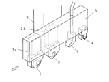
図1は本発明の加工方法を実施する際に使用される加工装置Aの一実施例を示す斜視図である。加工装置Aは、略水平方向(Y方向)に移動可能で、かつ、水平面内で回転可能なテーブル10を備えている。テーブル10はガラス基板Wを保持するための真空吸着機構(図示せず)を備えている。 FIG. 1 is a perspective view showing an embodiment of a processing apparatus A used in carrying out the processing method of the present invention. The processing apparatus A includes a table 10 that can move in a substantially horizontal direction (Y direction) and that can rotate in a horizontal plane. The table 10 includes a vacuum suction mechanism (not shown) for holding the glass substrate W.
テーブル10を挟んで設けてある両側の支持柱11,11と、X方向に延びるガイドバー12とで構成されるブリッジ13は、テーブル10上を跨ぐように設けてあり、図示外の移動機構によりY方向に移動できるように形成されている。スライダ14は、ガイドバー12に形成したガイド15に沿って移動可能に取り付けられ、モータ16の回転によりX方向に移動する。スライダ14には後述する固定刃1やカッターホイール2などを保持する取付ベース5が上下移動可能なステー7を介して取り付けられている。
A
図2並びに図3に示すように、取付ベース5には固定刃1、カッターホイール2、塵芥物を除去する吸引装置3、押さえローラ4が、固定刃1を先頭にして順次同一直線上に並べられた状態で取り付けられている。
As shown in FIGS. 2 and 3, the mounting
図4は、固定刃1の断面図である。固定刃1は、焼結ダイヤや超硬合金等の超硬質材料で造られ、刃先稜線角Σが小さくて鋭利な刃に形成されている。この刃先稜線角Σは25度〜40度の範囲、特に30度が好ましい。また固定刃1は、上下調節機構1dにより上下位置が微調整できるようになっている。
FIG. 4 is a cross-sectional view of the fixed
図5はカッターホイールの断面図、図6はその一部拡大図である。カッターホイール2は、固定刃1と同様に、焼結ダイヤや超硬合金等の超硬質材料で造られている。またこのカッターホイール2は、先端部分に稜線角αが大きなガラススクライブ用刃先2aが形成され、該ガラススクライブ用刃先2aの左右に形成される第1の傾斜面2bから連続して第2の傾斜面2cが形成されている。この左右の第2の傾斜面2c,2cに沿った仮想直線の交差する角度βが前記刃先の稜線角αより小さく形成されており、これにより、刃の左右両面が2段角度の傾斜面にしてある。
前記した刃先2aの稜線角αは80度〜160度、通常は90度〜145度、特に90度〜130度程度が好ましく、第2の傾斜面に沿った仮想直線の交差する角度βは10度〜70度、通常は15度〜55度、例えば25度〜40度、特に30度程度とするのが好ましい。また、カッターホイール2は、固定刃1と同様に、上下調節機構2d(図2参照)により上下位置が微調整できるようになっている。
FIG. 5 is a sectional view of the cutter wheel, and FIG. 6 is a partially enlarged view thereof. The
The edge angle α of the cutting edge 2a described above is preferably 80 ° to 160 °, usually 90 ° to 145 °, particularly preferably about 90 ° to 130 °, and the angle β at which the imaginary straight line along the second inclined surface intersects is 10 It is preferable to set the angle to 70 degrees, usually 15 degrees to 55 degrees, for example, 25 degrees to 40 degrees, particularly about 30 degrees. The
次に、上記加工装置Aによる加工動作について説明する。
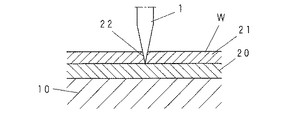
図8〜図11は、樹脂層が形成されたガラス基板を分断加工する際の手順を示す図である。本発明によってスクライブされるガラス基板Wは、ガラス板20の一方の面に薄い樹脂層21が形成されたタッチパネル等の基板である。このガラス基板Wを、図8に示すように樹脂層21が上側になるようにテーブル10上へ載置し、固定する。このあと取付ベース5を降下させて固定刃1、カッターホイール2をスクライブ位置に位置合わせした状態で、取付ベース5の固定刃1が先導となるようにガラス基板Wに押しつけて移動させる。
Next, the processing operation by the processing apparatus A will be described.
8-11 is a figure which shows the procedure at the time of parting the glass substrate in which the resin layer was formed. The glass substrate W scribed by the present invention is a substrate such as a touch panel in which a
この移動によって、まず、鋭利な固定刃1によって図8に示すように樹脂層21に切溝22が加工される。このとき、固定刃1の先端がガラス板20に当たらないような位置設定をしておく。これにより樹脂層21だけが鋭利な固定刃1によってきれいに切溝22が加工される。
By this movement, first, the
次いで、図9に示すように、後続のカッターホイール2が切溝22に沿ってガラス板20を圧接しながら転動して、ガラス板20にスクライブ溝23が形成される。この際、カッターホイール2の刃先稜線角αがガラススクライブ用に適した大きな角度で形成されているので、効果的にガラス板20にスクライブ溝23を加工することができる。また、この刃先2a部分を除く第2の傾斜面2cの角度βが小さく形成されているので、樹脂層の切溝22に嵌り込むカッターホイール2の先端部分の厚みを薄くでき、これにより切溝22をカッターホイール2で無理に押し広げる作用を小さく抑えることができて、切溝22の周縁部分が破壊されたり、引き裂かれたりすることをなくすことができる。
Next, as shown in FIG. 9, the
このあと、後続の吸引装置3によって、ガラス板20のスクライブ等によって生じた微細な塵芥物が吸引除去され、次いで切溝22の縁部に生じた僅かに盛り上がるバリ22aが、後続の押さえローラ4で平坦かつきれいに押しならされる(図10,図11参照)。これにより高品質の加工を行うことができる。
Thereafter, the fine dust generated by the scribing of the
上記実施例では、ガラス基板Wの樹脂層21に切溝22を加工するのに固定刃1を使用したが、これに代えて図7に示すように、レーザ光照射光学系6を取付ベース5に取り付け、レーザ光で切溝22を加工(レーザアブレーション加工)するようにしてもよい。
In the above embodiment, the fixed
また本発明では、加工されるガラス基板Wの材質によって、カッターホイール2の後続に配置される吸引装置3、押さえローラ4のいずれか一方、もしくは、その両方を省略することも可能である。
Moreover, in this invention, it is also possible to abbreviate | omit either the
以上本発明の代表的な実施例について説明したが、本発明は必ずしも上記の実施形態に限られるものではない。例えば、上記実施例では取付ベース5をガラス基板Wに対して移動させたが、取付ベース5を固定してガラス基板Wを移動させるようにしてもよい。その他本発明では、その目的を達成し、請求の範囲を逸脱しない範囲内で適宜修正、変更することが可能である。
さらに、以上の説明では、樹脂層が形成されたガラス基板を分断加工する際の手順を例にとって説明したが、本発明は、樹脂層が形成されたガラス基板以外の樹脂層が形成された脆性材料基板(例えば、セラミックス基板、半導体材料基板)にも適宜適用することができる。
While typical examples of the present invention have been described above, the present invention is not necessarily limited to the above-described embodiments. For example, in the above embodiment, the mounting
Further, in the above description, the procedure for dividing the glass substrate on which the resin layer is formed is described as an example. However, the present invention is brittle in which a resin layer other than the glass substrate on which the resin layer is formed is formed. The present invention can be appropriately applied to a material substrate (for example, a ceramic substrate or a semiconductor material substrate).
本発明の分断方法は、タッチパネルのように、ガラス板の一方の面に薄い樹脂層が形成されたガラス基板等の脆性材料の表面に樹脂層が形成された脆性材料基板を分断加工するのに利用することができる。 The cutting method of the present invention is for cutting a brittle material substrate having a resin layer formed on the surface of a brittle material such as a glass substrate having a thin resin layer formed on one surface of a glass plate, such as a touch panel. Can be used.
1 固定刃
2 カッターホイール
2a カッターホイールのガラススクライブ用刃先
2b 第1の傾斜面
2c 第2の傾斜面
3 吸引装置
4 押さえローラ
5 取付ベース
6 レーザ光照射光学系
20 ガラス基板のガラス板
21 ガラス基板の樹脂層
22 切溝
23 スクライブ溝
W ガラス基板
α カッターホイールの刃先稜線角
β カッターホイールの第2の傾斜面の角度
Σ 固定刃の刃先稜線角
DESCRIPTION OF
Claims (9)
樹脂層上面から樹脂分離手段により樹脂層に切溝を加工し、
刃先先端部分に稜線角αを有する脆性材料スクライブ用刃先を備え、該脆性材料スクライブ用刃先の左右に形成される第1の傾斜面から連続する第2の傾斜面を備え、前記刃先先端から前記第1の傾斜面までの深さは前記樹脂層の厚さよりも小さく形成され、前記左右の第2の傾斜面に沿った仮想直線の交差する角度βが前記先端部分の稜線角αより小さくした2段角度の傾斜面を備えた構造のカッターホイールを使用し、このカッターホイールを前記樹脂層上面から前記切溝に沿って押しつけながら転動させることによって脆性材料板にスクライブ溝を形成する脆性材料基板の加工方法。 A method for processing a brittle material substrate in which a resin layer is formed on one surface of a brittle material plate,
Cut grooves in the resin layer from the top surface of the resin layer by means of resin separation,
Comprising a cutting edge for a brittle material scribing having ridges angle α to the blade tip portion, a second inclined surface continuous from the first inclined surface formed on the right and left edge for該脆material scribing, said from the cutting edge tip The depth to the first inclined surface is formed smaller than the thickness of the resin layer, and the angle β at which the imaginary straight line along the left and right second inclined surfaces intersects is smaller than the ridge line angle α of the tip portion. A brittle material that uses a cutter wheel having a two-step angled inclined surface and rolls the cutter wheel while pressing the cutter wheel along the kerf from the upper surface of the resin layer to form a scribe groove in the brittle material plate Substrate processing method.
前記樹脂層上面の側に配置され、前記樹脂層に切溝を加工するための固定刃もしくはレーザ光照射光学系と、
前記固定刃もしくはレーザ光照射光学系と同一直線上に配置され、かつ、樹脂層上面の側から切溝に沿って転動させることにより脆性材料板にスクライブ溝を形成するカッターホイールとを備え、
前記カッターホイールは、刃先先端部分に稜線角αを有する脆性材料スクライブ用刃先を備え、前記脆性材料スクライブ用刃先の左右に形成される第1の傾斜面から連続して第2の傾斜面が設けられ、前記刃先先端から前記第1の傾斜面までの深さは前記樹脂層の厚さよりも小さく形成され、前記左右の第2の傾斜面に沿った仮想直線の交差する角度βが前記先端部分の稜線角αより小さく形成されており、これにより刃の左右両面が2段角度の傾斜面で形成されていることを特徴とする脆性材料基板の加工装置。 A brittle material substrate processing apparatus having a resin layer formed on one surface,
A fixed blade or a laser beam irradiation optical system, which is disposed on the upper surface side of the resin layer, for processing a kerf in the resin layer;
A cutter wheel that is arranged on the same straight line as the fixed blade or the laser beam irradiation optical system, and that forms a scribe groove in the brittle material plate by rolling along the groove from the resin layer upper surface side,
The cutter wheel includes a brittle material scribe cutting edge having a ridge angle α at a tip end portion of the blade edge, and a second inclined surface is provided continuously from the first inclined surfaces formed on the left and right sides of the brittle material scribe blade edge. A depth from the tip of the blade tip to the first inclined surface is smaller than a thickness of the resin layer, and an angle β intersecting an imaginary straight line along the left and right second inclined surfaces is defined as the tip portion. An apparatus for processing a brittle material substrate, characterized in that it is formed smaller than the ridge line angle α of the blade, whereby the left and right sides of the blade are formed with inclined surfaces having a two-step angle.
Priority Applications (5)
| Application Number | Priority Date | Filing Date | Title |
|---|---|---|---|
| JP2009179852A JP5438422B2 (en) | 2009-07-31 | 2009-07-31 | Method and apparatus for processing brittle material substrate |
| KR20100044317A KR101200788B1 (en) | 2009-07-31 | 2010-05-12 | Method and apparatus for processing substrate of brittle material |
| TW99116978A TWI432387B (en) | 2009-07-31 | 2010-05-27 | Processing method and processing device for brittle material substrate |
| CN 201010202851 CN101987775B (en) | 2009-07-31 | 2010-06-11 | Method and apparatus for processing brittle material substrate |
| EP10165986.0A EP2279983A3 (en) | 2009-07-31 | 2010-06-15 | Method and Apparatus for Processing Brittle Material Substrate |
Applications Claiming Priority (1)
| Application Number | Priority Date | Filing Date | Title |
|---|---|---|---|
| JP2009179852A JP5438422B2 (en) | 2009-07-31 | 2009-07-31 | Method and apparatus for processing brittle material substrate |
Publications (2)
| Publication Number | Publication Date |
|---|---|
| JP2011031483A JP2011031483A (en) | 2011-02-17 |
| JP5438422B2 true JP5438422B2 (en) | 2014-03-12 |
Family
ID=42938248
Family Applications (1)
| Application Number | Title | Priority Date | Filing Date |
|---|---|---|---|
| JP2009179852A Expired - Fee Related JP5438422B2 (en) | 2009-07-31 | 2009-07-31 | Method and apparatus for processing brittle material substrate |
Country Status (5)
| Country | Link |
|---|---|
| EP (1) | EP2279983A3 (en) |
| JP (1) | JP5438422B2 (en) |
| KR (1) | KR101200788B1 (en) |
| CN (1) | CN101987775B (en) |
| TW (1) | TWI432387B (en) |
Families Citing this family (29)
| Publication number | Priority date | Publication date | Assignee | Title |
|---|---|---|---|---|
| JP2011218607A (en) * | 2010-04-06 | 2011-11-04 | Sharp Corp | Substrate dividing apparatus and substrate dividing method |
| JP5244202B2 (en) * | 2011-01-27 | 2013-07-24 | 三星ダイヤモンド工業株式会社 | Method for scribing a brittle material substrate |
| EP3421232B1 (en) | 2011-05-13 | 2021-12-15 | Nippon Electric Glass Co., Ltd. | Method for processing a laminate |
| JP5271394B2 (en) * | 2011-07-20 | 2013-08-21 | 三星ダイヤモンド工業株式会社 | Laser scribing equipment |
| KR101144264B1 (en) | 2011-10-07 | 2012-05-11 | 전선화 | Strengthened glass window manufacturing method for display and strengthened glass window using the same |
| TWI458108B (en) * | 2011-12-07 | 2014-10-21 | Ind Tech Res Inst | Trench scribing apparatus and trench scribing method |
| JP6043150B2 (en) * | 2012-10-29 | 2016-12-14 | 三星ダイヤモンド工業株式会社 | Breaking apparatus for laminated brittle material substrate and method for breaking laminated brittle material substrate |
| ES2478115B1 (en) * | 2012-12-18 | 2015-04-28 | Bellota Herramientas, S.A. | BLADE FOR CUTTING TOOL OF A CERAMIC CUTTING MACHINE |
| CN103085106B (en) * | 2013-02-01 | 2015-09-30 | 四川虹视显示技术有限公司 | Oled substrate diced system |
| JP6357746B2 (en) * | 2013-09-24 | 2018-07-18 | 三星ダイヤモンド工業株式会社 | Scribing wheel, holder unit, scribing device, scribing wheel manufacturing method and scribing method |
| JP6268917B2 (en) * | 2013-10-25 | 2018-01-31 | 三星ダイヤモンド工業株式会社 | Break device |
| CN103739191A (en) * | 2013-11-13 | 2014-04-23 | 上海和辉光电有限公司 | Cutting dust suction apparatus and cutting method |
| CN104766904B (en) * | 2014-01-06 | 2017-01-11 | 大族激光科技产业集团股份有限公司 | CIGS thin film solar cell scribing equipment |
| JP6332618B2 (en) * | 2014-04-24 | 2018-05-30 | 三星ダイヤモンド工業株式会社 | Scribing cutter wheel and scribing device |
| JP6287547B2 (en) * | 2014-04-28 | 2018-03-07 | 三星ダイヤモンド工業株式会社 | Inverting device for brittle material substrate |
| JP6299405B2 (en) * | 2014-05-13 | 2018-03-28 | 旭硝子株式会社 | Method for producing composite and method for producing laminate |
| EP3034478B1 (en) * | 2014-12-18 | 2022-11-16 | Macotec S.R.L. | Apparatus for treating the surface of sheet elements, such as glass sheets |
| KR102446856B1 (en) * | 2016-06-29 | 2022-09-23 | 삼성디스플레이 주식회사 | Cover window and method for manufacturing the same |
| CN107363877B (en) * | 2017-07-25 | 2019-02-12 | 武汉华星光电半导体显示技术有限公司 | A kind of cutter device and cutting method |
| JP6949371B2 (en) * | 2017-12-15 | 2021-10-13 | 三星ダイヤモンド工業株式会社 | Board divider |
| CN108059335B (en) * | 2018-01-04 | 2021-01-26 | 京东方科技集团股份有限公司 | Cutting method |
| DE102018107697B4 (en) | 2018-03-29 | 2020-12-10 | Hegla Boraident Gmbh & Co. Kg | Stripping devices and methods for stripping glass panels, preferably laminated glass panels |
| DE102018010277B4 (en) | 2018-03-29 | 2022-01-13 | Hegla Boraident Gmbh & Co. Kg | Decoating process and use of a decoating device for decoating glass panels, preferably laminated glass panels |
| CN108588636B (en) * | 2018-04-26 | 2019-10-01 | 山东大学 | A method of improving fragile material machining surface integrality |
| CN109333831A (en) * | 2018-12-13 | 2019-02-15 | 佛山市爱陶机电设备有限公司 | A kind of ceramic tile cutting technique and ceramic tile cutting equipment |
| CN109808080A (en) * | 2019-03-26 | 2019-05-28 | 云浮市科特机械有限公司 | A kind of double-pole cutting technique |
| CN111844478B (en) * | 2020-06-29 | 2022-03-18 | 深圳市鸿昇自动化设备有限公司 | Mobile phone screen cutting and processing equipment and mobile phone screen cutting and processing method |
| CN112757506B (en) * | 2020-12-31 | 2022-07-05 | 青岛建设集团股份有限公司 | Slope and wall body joint slotting device with centralizing and limiting functions |
| CN113696248B (en) * | 2021-10-29 | 2022-01-07 | 四川英创力电子科技股份有限公司 | Equipment and method for forming deep groove on PTFE high-frequency circuit board with high precision |
Family Cites Families (18)
| Publication number | Priority date | Publication date | Assignee | Title |
|---|---|---|---|---|
| JPS62158129A (en) * | 1985-12-27 | 1987-07-14 | Kyocera Corp | Wheel cutter for cutting glass |
| JPH01256956A (en) * | 1988-04-08 | 1989-10-13 | Shinkiyokutou Sangyo Kk | Manufacture of surface material for hygienic absorbent |
| JPH11105141A (en) * | 1997-08-04 | 1999-04-20 | Kyodo Giken Kagaku Kk | Porous film and its manufacture |
| JP3759317B2 (en) * | 1998-08-04 | 2006-03-22 | トーヨー産業株式会社 | Cutter wheel dedicated to glass cutting |
| JP2001058317A (en) * | 1999-08-20 | 2001-03-06 | Berudekkusu:Kk | Method and apparatus for scribing |
| JP4433555B2 (en) * | 2000-03-23 | 2010-03-17 | 坂東機工株式会社 | Glass plate processing method and apparatus |
| JP2001347416A (en) * | 2000-06-06 | 2001-12-18 | Matsushita Electric Ind Co Ltd | Cutting device and cutting method |
| JP2002060234A (en) * | 2000-08-16 | 2002-02-26 | Nippon Electric Glass Co Ltd | Method and device for cutting off transparent plate |
| CN101042487A (en) * | 2001-11-08 | 2007-09-26 | 夏普株式会社 | Liquid crystal panel |
| KR100633488B1 (en) * | 2001-11-08 | 2006-10-13 | 샤프 가부시키가이샤 | Method and device for parting glass substrate, and liquid crystal panel manufacturing device |
| KR100568091B1 (en) * | 2003-03-17 | 2006-04-07 | 신한다이아몬드공업 주식회사 | A Cone Type PCD Scriber And Glove Making Apparatus Of Scriber |
| KR100923680B1 (en) * | 2003-04-29 | 2009-10-28 | 엘지디스플레이 주식회사 | Apparatus for cutting liquid crystal display panel |
| JP5022602B2 (en) * | 2004-02-02 | 2012-09-12 | 三星ダイヤモンド工業株式会社 | Cutter wheel and method for scribing and dividing brittle material substrate using the same |
| CN1321082C (en) * | 2004-10-28 | 2007-06-13 | 中国洛阳浮法玻璃集团有限责任公司 | Ultra-thin glass on-line oil trace-free cutting lubricant and its specific breaker bar |
| KR100596130B1 (en) | 2006-02-06 | 2006-07-03 | 주식회사 탑 엔지니어링 | Apparatus for cutting substrate of flat panel display |
| JP4219945B2 (en) * | 2006-08-10 | 2009-02-04 | トーヨー産業株式会社 | Cutter foil for glass cutting |
| JP2008094635A (en) * | 2006-10-06 | 2008-04-24 | Citizen Seimitsu Co Ltd | Cutter holder unit and scribing device equipped with the cutter holder unit |
| CN102672741B (en) * | 2008-01-15 | 2015-06-03 | 三星钻石工业股份有限公司 | Cutting blade |
-
2009
- 2009-07-31 JP JP2009179852A patent/JP5438422B2/en not_active Expired - Fee Related
-
2010
- 2010-05-12 KR KR20100044317A patent/KR101200788B1/en active IP Right Grant
- 2010-05-27 TW TW99116978A patent/TWI432387B/en not_active IP Right Cessation
- 2010-06-11 CN CN 201010202851 patent/CN101987775B/en not_active Expired - Fee Related
- 2010-06-15 EP EP10165986.0A patent/EP2279983A3/en not_active Withdrawn
Also Published As
| Publication number | Publication date |
|---|---|
| TW201103874A (en) | 2011-02-01 |
| CN101987775B (en) | 2013-01-09 |
| EP2279983A3 (en) | 2013-09-11 |
| JP2011031483A (en) | 2011-02-17 |
| EP2279983A2 (en) | 2011-02-02 |
| KR101200788B1 (en) | 2012-11-13 |
| CN101987775A (en) | 2011-03-23 |
| TWI432387B (en) | 2014-04-01 |
| KR20110013203A (en) | 2011-02-09 |
Similar Documents
| Publication | Publication Date | Title |
|---|---|---|
| JP5438422B2 (en) | Method and apparatus for processing brittle material substrate | |
| JP5078354B2 (en) | Cutter wheel manufacturing method | |
| US20080311817A1 (en) | Display device having pair of glass substrates and method for cutting it | |
| KR101140164B1 (en) | Method?of?forming?scribe?line?on?substrate?of?brittle?material?and?scribe?line?forming?apparatus | |
| JP5210356B2 (en) | Method for scribing a brittle material substrate | |
| JP5331078B2 (en) | Method for scribing a brittle material substrate | |
| JP2009132614A (en) | Method of scribing brittle material substrate and device therefor | |
| JP5210355B2 (en) | Method for scribing a brittle material substrate | |
| JP5478957B2 (en) | Cleaving method of brittle material substrate | |
| JP2010150068A (en) | Method for breaking brittle material substrate | |
| JP5779074B2 (en) | Method for scribing tempered glass substrate | |
| TW201323363A (en) | Scribing method and scribing device of reinforced glass substrate | |
| JP2003292332A (en) | Scribing method and scribing device | |
| JP5309107B2 (en) | Fragment material substrate cutting device | |
| JP2014031293A (en) | Scribing method of brittle material substrate | |
| TWI482693B (en) | The cutting method of the laminated body and the cutter used in the method | |
| WO2004009311A1 (en) | Method of scribing on brittle matetrial, scribe head, and scribing apparatus with the scribe head | |
| JP3847864B2 (en) | Glass scriber | |
| JP2014031292A (en) | Scribing method of tempered glass substrate | |
| JP5330907B2 (en) | Method for dividing brittle material substrate | |
| KR20160003583A (en) | Scribing apparatus and scribing method for tempered glass substrate | |
| TWI254702B (en) | Cutter wheel for nonmetal material, and method and device for scribing using the cutter wheel | |
| KR101819608B1 (en) | Method and apparatus for cutting glass laminates | |
| KR20130110054A (en) | Scribing apparatus and scribing method for tempered glass substrate | |
| TW202404772A (en) | Groove processing tool and groove processing method capable of peeling off a resin film in a strip shape with a thin resin film remaining at the bottom of the groove |
Legal Events
| Date | Code | Title | Description |
|---|---|---|---|
| A621 | Written request for application examination |
Free format text: JAPANESE INTERMEDIATE CODE: A621 Effective date: 20120202 |
|
| A131 | Notification of reasons for refusal |
Free format text: JAPANESE INTERMEDIATE CODE: A131 Effective date: 20130423 |
|
| A977 | Report on retrieval |
Free format text: JAPANESE INTERMEDIATE CODE: A971007 Effective date: 20130425 |
|
| A521 | Written amendment |
Free format text: JAPANESE INTERMEDIATE CODE: A523 Effective date: 20130614 |
|
| TRDD | Decision of grant or rejection written | ||
| A01 | Written decision to grant a patent or to grant a registration (utility model) |
Free format text: JAPANESE INTERMEDIATE CODE: A01 Effective date: 20131119 |
|
| A61 | First payment of annual fees (during grant procedure) |
Free format text: JAPANESE INTERMEDIATE CODE: A61 Effective date: 20131213 |
|
| R150 | Certificate of patent or registration of utility model |
Ref document number: 5438422 Country of ref document: JP Free format text: JAPANESE INTERMEDIATE CODE: R150 Free format text: JAPANESE INTERMEDIATE CODE: R150 |
|
| LAPS | Cancellation because of no payment of annual fees |