JP5419663B2 - Motor control device - Google Patents
Motor control device Download PDFInfo
- Publication number
- JP5419663B2 JP5419663B2 JP2009277573A JP2009277573A JP5419663B2 JP 5419663 B2 JP5419663 B2 JP 5419663B2 JP 2009277573 A JP2009277573 A JP 2009277573A JP 2009277573 A JP2009277573 A JP 2009277573A JP 5419663 B2 JP5419663 B2 JP 5419663B2
- Authority
- JP
- Japan
- Prior art keywords
- motor
- rotation
- control
- phase
- circuit
- Prior art date
- Legal status (The legal status is an assumption and is not a legal conclusion. Google has not performed a legal analysis and makes no representation as to the accuracy of the status listed.)
- Expired - Fee Related
Links
Images


Landscapes
- Control Of Motors That Do Not Use Commutators (AREA)
Description
本発明は、モータ各相コイルの誘起電圧に基づいてロータ回転状態を検知し、モータ各相コイルへの位相通電制御(以下、「転流」という。)によりモータ制御を行うモータ制御装置に関する。 The present invention relates to a motor control device that detects a rotor rotation state based on an induced voltage of each phase coil of a motor and performs motor control by phase energization control (hereinafter referred to as “commutation”) to each phase coil of the motor.
従来、センサレスブラシレスモータにおいて、各相コイルの誘起電圧(逆起電力電圧)と中性電圧を比較することにより、ロータ回転位置を検出し、インバータ回路で各相コイルの電流を切り替え駆動し、モータ回転駆動制御を行うものが知られている(例えば、特許文献1参照)。 Conventionally, in a sensorless brushless motor, the rotor rotation position is detected by comparing the induced voltage (counterelectromotive force voltage) of each phase coil and the neutral voltage, and the current of each phase coil is switched by an inverter circuit. What performs rotation drive control is known (for example, refer patent document 1).
しかしながら、従来のモータ制御装置にあっては、逆起電力電圧が充分に発生していない起動時及び低回転時において、ロータ回転位相と同期した制御が困難であり、非同期制御となるため、異音、回転脱調、停止等が発生してしまう、という問題があった。 However, in the conventional motor control device, it is difficult to control in synchronization with the rotor rotation phase at the time of start-up and low rotation at which the back electromotive force voltage is not sufficiently generated. There was a problem that sound, rotational step-out, stop, etc. would occur.
つまり、各相コイルで発生する逆起電力電圧と基準電圧である中性電圧(以下、中点電圧又は中点電位)を比較する制御においては、逆起電力電圧と中点電圧が一致する場合を逆起電力電圧のゼロクロスタイミングとし、これを転流タイミングの基点とすることにより回転駆動制御が行われる。しかし、逆起電力が充分に発生しないことにより電圧レベルが低くなる起動時及び低回転時においては、逆起電力電圧と中点電圧のそれぞれの電圧ばらつきによりゼロクロスタイミングが検知できなかったり、位相がずれたりするため、ロータの回転位相と同期した制御が困難であり、ゼロクロスタイミングの検知ができるまで位相非同期制御(例えば、強制駆動)を継続して行わなければならなかった。 In other words, in the control that compares the counter electromotive force voltage generated in each phase coil with the neutral voltage that is the reference voltage (hereinafter referred to as the midpoint voltage or midpoint potential), the back electromotive force voltage and the midpoint voltage match. Is used as the zero cross timing of the back electromotive force voltage, and this is used as the base point of the commutation timing, so that the rotational drive control is performed. However, at the time of start-up and low rotation when the back electromotive force is not sufficiently generated and the voltage level is low, the zero cross timing cannot be detected due to variations in the back electromotive force voltage and the midpoint voltage, or the phase is Therefore, it is difficult to control in synchronization with the rotational phase of the rotor, and phase asynchronous control (for example, forced driving) must be continuously performed until the zero cross timing can be detected.
本発明は、上記問題に着目してなされたもので、モータ起動時、応答良くモータ回転駆動制御を開始することができると共に、非同期制御が継続することによる異音,回転脱調,停止,過電流等を回避あるいは低減することができるモータ制御装置を提供することを目的とする。 The present invention has been made paying attention to the above-mentioned problem. When the motor is started, the motor rotation drive control can be started with good response, and the asynchronous noise continues, abnormal noise, rotational step-out, stop, overload. It is an object of the present invention to provide a motor control device that can avoid or reduce current and the like.
上記目的を達成するため、本発明のモータ制御装置では、センサレスブラシレスモータと、制御回路と、駆動トランジスタ回路と、逆起電力検知回路と、を備え、前記センサレスブラシレスモータの各相コイルにて発生する逆起電力の電圧ゼロクロス検出に基づいてモータ回転位置情報を取得し、前記モータ回転位置情報を用いた各相コイルへの転流制御により回転駆動制御を行う。
このモータ制御装置において、前記逆起電力検知回路の比較基準電位を発生する比較基準電位回路と、前記比較基準電位を前記センサレスブラシレスモータの各相コイルに供給するモータ相コイルバイアス回路と、を設け、
前記制御回路は、モータ起動時、前記各相コイルの全てをオープンにする全相オープンと設定デューティ駆動とを繰り返すクローズドループ制御を行い、全相オープン中における逆起電力と比較基準電位の電圧ゼロクロス検出に基づき、前記センサレスブラシレスモータが正回転・停止・逆回転のうち何れの状態であるかの回転状態検知を実行し、回転状態検知による判定結果に応じ、前記センサレスブラシレスモータが正回転となる位相による転流制御へ移行するモータ起動制御手段を有する。
In order to achieve the above object, the motor control device of the present invention comprises a sensorless brushless motor, a control circuit, a drive transistor circuit, and a counter electromotive force detection circuit, and is generated in each phase coil of the sensorless brushless motor. Motor rotation position information is acquired based on the detection of the voltage zero cross of the back electromotive force, and rotation drive control is performed by commutation control to each phase coil using the motor rotation position information.
In this motor control device, a comparison reference potential circuit that generates a comparison reference potential of the back electromotive force detection circuit and a motor phase coil bias circuit that supplies the comparison reference potential to each phase coil of the sensorless brushless motor are provided. ,
The control circuit performs closed-loop control that repeats all-phase open and set duty drive to open all the phase coils when the motor is started, and the counter-electromotive force and the comparison reference potential voltage zero-cross during all-phase open Based on the detection, the sensorless brushless motor performs a rotation state detection as to whether the sensorless brushless motor is in a normal rotation, stop, or reverse rotation, and the sensorless brushless motor becomes a normal rotation according to a determination result by the rotation state detection. Motor start control means for shifting to commutation control by phase is provided.
例えば、従来例のモータ制御装置でモータ起動を行う場合、極低回転数から電圧ゼロクロス検出ができないため、先ず、停止位相を決めるための位置決め駆動を実施し(モータが停止するまでの数秒間)、その後、その位相から回転位相と非同期の制御(強制駆動)を電圧ゼロクロス検出ができる高回転状態になるまで継続し、転流位相や転流タイミングが確定した後、正回転となる位相による転流制御へ移行する。
これに対し、本発明は、比較基準電位回路とモータ相コイルバイアス回路を有し、全相オープンのときに極低回転数から電圧ゼロクロス検出ができる回路構成を備えると共に、モータ起動時、全相オープンと設定デューティ駆動とを繰り返すクローズドループ制御を行い、全相オープン中、極低回転数からの電圧ゼロクロス検出に基づきモータ回転状態の検知を実行することで、正回転を前提としなくても、正回転となる位相による転流制御へ移行できる制御を備えるものとしている。つまり、モータ起動時からクローズドループ制御を可能にし、位置決め駆動と強制駆動を省略したモータ起動制御を採用している。
このため、従来例のように、モータ起動の開始から電圧ゼロクロス検出ができる高回転状態になるまでの間、非同期制御を継続させる必要が無く、位置決め駆動や強制駆動による非同期制御が継続することによる異音,回転脱調,停止,過電流等を回避あるいは低減することができる。
更に、モータ起動開始から費やされる位置決め駆動のための所要時間や強制駆動のための所要時間が省略され、クローズドループ制御中に転流位相や転流タイミングが確定したら、応答良く位相同期によるモータ回転駆動制御を開始することができる。
この結果、モータ起動時、応答良くモータ回転駆動制御を開始することができると共に、非同期制御が継続することによる異音,回転脱調,停止,過電流等を回避あるいは低減することができる。
For example, when starting a motor with a conventional motor control device, voltage zero cross cannot be detected from an extremely low rotational speed, so positioning driving is first performed to determine a stop phase (several seconds until the motor stops) After that, control (forced drive) that is asynchronous with the rotation phase is continued from that phase until a high rotation state where voltage zero-crossing detection is possible. Transition to flow control.
On the other hand, the present invention has a comparison reference potential circuit and a motor phase coil bias circuit, and has a circuit configuration capable of detecting a voltage zero cross from an extremely low rotational speed when all phases are open. Closed loop control that repeats open and set duty drive is performed, and while all phases are open, by detecting the motor rotation state based on voltage zero cross detection from extremely low rotation speed, even if it does not assume normal rotation, Control capable of shifting to commutation control by a phase that becomes forward rotation is provided. In other words, closed loop control is possible from the time of motor startup, and motor startup control is employed in which positioning drive and forced drive are omitted.
For this reason, unlike the conventional example, it is not necessary to continue the asynchronous control from the start of the motor to the high rotation state where the voltage zero cross detection can be performed, and the asynchronous control by the positioning drive or the forced drive is continued. Abnormal noise, rotational step-out, stop, overcurrent, etc. can be avoided or reduced.
Furthermore, the time required for positioning drive and the time required for forced drive that are spent from the start of motor startup are omitted, and if the commutation phase and commutation timing are determined during closed-loop control, the motor rotation by phase synchronization is responsive. Drive control can be started.
As a result, motor rotation drive control can be started with good response when the motor is started, and abnormal noise, rotational step-out, stop, overcurrent, and the like due to continuing asynchronous control can be avoided or reduced.
以下、本発明のモータ制御装置を実現する最良の形態を、図面に示す実施例1〜実施例5に基づいて説明する。 Hereinafter, the best mode for realizing a motor control device of the present invention will be described based on Examples 1 to 5 shown in the drawings.
まず、構成を説明する。
図1は、実施例1のモータ制御装置A1を示す全体回路構成図である。以下、図1に基づき装置構成を説明する。
First, the configuration will be described.
FIG. 1 is an overall circuit configuration diagram illustrating a motor control device A1 according to the first embodiment. The apparatus configuration will be described below with reference to FIG.
実施例1のモータ制御装置A1は、図1に示すように、制御回路2と、駆動TR回路3(駆動トランジスタ回路)、BEMF検知回路4(逆起電力検知回路)と、センサレスブラシレスモータ5と、モータ相コイルバイアス回路6、比較基準電位回路7と、回転数指示入力8と、を備えている。なお、「BEMF(Back Electromotive Forceの略)」とは、逆起電力の意味であり、以下の説明で用いる「BEMF」は、コイルで発生する逆起電力による電圧(=発電電圧)をあらわす。
As shown in FIG. 1, the motor control device A1 according to the first embodiment includes a
前記制御回路2は、センサレスブラシレスモータ5の起動制御や回転駆動制御や停止制御や回転復帰制御、等を行うモータ制御回路であり、例えば、専用制御IC(ASIC),マイコン等により構成される。この制御回路2は、図示しない外部ユニットやセンサ等からセンサレスブラシレスモータ5に対する回転数指示入力8を入力すると共に、BEMF検知回路4からBEMF電圧ゼロクロス信号(以下、ゼロクロス信号)を入力する。そして、これらの入力情報に基づき、制御演算を行い、駆動TR回路3へPWMデューティ制御信号(以下、PWM信号)を出力する。なお、制御回路用の電源、信号I/F(インターフェース)は、図示を省略する。
The
前記駆動TR回路3は、三相(U相とV相とW相)の各相に対応するアッパー側のスイッチ素子(Qu1,Qv1,Qw1)とロワ側のスイッチ素子(Qu2,Qv2,Qw2)によりブリッジ回路を構成し、インバータとして機能するインバータ回路である。なお、スイッチ素子の制御信号(ベース入力、ゲート入力)は、制御回路2からのPWM信号である。ここで、スイッチ素子のベース又はゲートを駆動する回路は、図示を省略する。例えば、U相回路について説明すると、電源電圧Vbatからグランドまでの間に、スイッチ素子Qu1,Qu2を配置し、その中間とセンサレスブラシレスモータ5のU相コイル5uを接続する。V相回路、W相回路についても同様に構成する。
The driving
前記BEMF検知回路4は、各相コイル5u,5v,5wで発生するBEMFのゼロクロスを検知する回路であり、各相コイル5u,5v,5wに対応して設けられた電圧比較器OP1〜OP3及び抵抗R1〜R3を備えている。つまり、電圧比較器OP1〜OP3のプラス入力端子には、各相コイル5u,5v,5wと駆動TR回路3の接続点50u,50v,50wの逆起電力電圧を検出するように、抵抗R1〜R3を介して入力する。更に、電圧比較器OP1〜OP3のマイナス入力端子には、比較基準電位回路7からの基準電圧を入力する。そして、電圧比較器OP1〜OP3において、基準電圧と各相コイル5u,5v,5wからのBEMFを比較し、その比較結果をゼロクロス信号として制御回路2へ出力する。
The
前記センサレスブラシレスモータ5は、車両用エアコンユニットのファンモータとして適用され、U相コイル5u,V相コイル5v,W相コイル5wをスター結線した三相モータである。このセンサレスブラシレスモータ5は、ロータに永久磁石を埋設し、ステータにコイルを巻き付けたブラシを用いないブラシレスモータであると共に、回転位置検出用のホール素子等を持たないセンサレスモータである。そして、コイル自体を回転位置検出用センサとし、各相コイル5u,5v,5wに発生するBEMFのゼロクロスを検出して、回転位置情報(ロータ位置情報)を得るようにしている。
The
前記モータ相コイルバイアス回路6は、予めBEMF検知回路4の比較基準電位を入力に加えておき、前記駆動TR回路3の全てのスイッチ素子をOFFとし、各相コイル5u,5v,5wを全てオープン(フローティング)にした時、各相コイル5u,5v,5wで発生するBEMFのゼロクロス電位(中点電位)を、前記比較基準電位にバイアスする回路であり、抵抗R4〜R6を備えている。この抵抗R4〜R6は、一方をそれぞれ、センサレスブラシレスモータ5の各相コイル5u,5v,5wと駆動TR回路3の接続点50u,50v,50wに接続する。そして、他方を一つに合わせて比較基準電位回路7の、電圧増圧器OP4(オペアンプ)の出力に接続する。
The motor phase
前記比較基準電位回路7は、モータ相コイル駆動時のノイズを含む駆動電圧波形が、モータ相コイルバイアス回路6の抵抗R4〜R6を介して回り込み、BEMF検知回路4の基準電位を変動させBEMF検知回路4が誤検知しないように、基準電圧を出力するボルテージフォロア回路であり、電圧増幅器OP4と抵抗R7,R8を備えている。この電圧増幅器OP4は、そのプラス入力端子に抵抗R7と抵抗R8の中間を接続し、抵抗R7,R8の分圧値が入力されるようにする。そして、電圧増幅器OP4のマイナス端子は、出力を入力して負帰還路とする。更に、電圧増幅器OP4の出力は、モータ相コイルバイアス回路6及びBEMF検知回路4の電圧比較器OP1〜OP3のマイナス入力端子に接続する。抵抗R7、R8は、電源電圧Vbatからグランド接地までの間に直列に設ける。本例では、抵抗R7、R8は同値とし、抵抗R7と抵抗R8の分圧値(接続点)が中点電位(1/2Vbat)となるようにしてある。
In the comparison reference
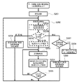
図2は、実施例1の制御回路2にて実行される非通電停止からのモータ起動制御処理の流れを示すフローチャートである(モータ起動制御手段)。以下、図2の各ステップについて説明する。
FIG. 2 is a flowchart showing the flow of the motor start control process from the deenergization stop executed by the
ステップS101では、非通電停止からのモータ起動時、センサレスブラシレスモータ5のモータ慣性質量と負荷に応じた必要最低限の時間と低デューティにより、モータ停止位置位相と無関係に任意の位相でモータ相コイルを駆動し、(初期)回転起動するオープンループ制御を行い、ステップS102へ進む。
In step S101, when starting the motor from the non-energized stop, the motor phase coil at an arbitrary phase regardless of the motor stop position phase due to the minimum required time and low duty according to the motor inertia mass and load of the
ステップS102では、ステップS101での回転起動に続き、センサレスブラシレスモータ5のモータ回転状態を検知する。すなわち、センサレスブラシレスモータ5の各相コイル5u,5v,5wの全てをオープンにする全相オープン制御を行い、全相オープン中における逆起電力電圧と比較基準電位のゼロクロス信号に基づき、回転位相と転流位相と転流タイミングを監視し、これら回転位相・転流位相・転流タイミングの全てが確定すると(ステップS102a)、次のセンサレスブラシレスモータ5のモータ回転方向の判定を行う(ステップS102b)。そして、モータ回転方向の判定により、判定結果が正回転状態であるとステップS103へ進み、判定結果が逆回転状態であるとステップS106へ進み、判定結果が停止状態であるとステップS107へ進む。
In step S102, following the rotation start in step S101, the motor rotation state of the
ステップS103では、ステップS102での正回転状態であるとの判定、あるいは、ステップS105でのゼロクロス検出有りの判断に続き、センサレスブラシレスモータ5の各相コイル5u,5v,5wへの転流制御により、センサレスブラシレスモータ5を正回転させる回転駆動制御を行い、ステップS104へ進む。
In step S103, following the determination of the normal rotation state in step S102 or the determination of the presence of zero cross detection in step S105, commutation control to each
ステップS104では、ステップS103での正回転転流に続き、BEMFゼロクロス検出に基づき、転流位相と転流タイミングを確定し、ステップS105へ進む。 In step S104, following the forward rotational commutation in step S103, the commutation phase and commutation timing are determined based on the BEMF zero cross detection, and the process proceeds to step S105.
ステップS105では、ステップS104でのBEMFゼロクロス検出に続き、BEMFゼロクロス検出の有無を判断し、BEMFゼロクロス検出有りと判断されるとステップS103へ戻り、BEMFゼロクロス検出無しと判断されるとステップS102へ戻る。 In step S105, following the BEMF zero-cross detection in step S104, the presence / absence of BEMF zero-cross detection is determined. If it is determined that the BEMF zero-cross detection is present, the process returns to step S103. .
ステップS106では、ステップS102での逆回転状態であるとの判定に続き、逆回転状態のセンサレスブラシレスモータ5の各相コイル5u,5v,5wに対し、正回転となる位相による回転方向修正の転流制御へ移行し、モータ停止を介することなく、所定時間だけ回転再起動を行い、ステップS102へ戻る。
In step S106, following the determination of the reverse rotation state in step S102, for each
ステップS107では、ステップS102での停止状態であるとの判定に続き、停止判定回数(位相を進めた回数)が、予め定めた設定回数N以上であるか否かを判断し、停止判定回数(位相を進めた回数)<Nであるとの判断時はステップS108に進み、停止判定回数(位相を進めた回数)≧Nであるとの判断時はステップS109へ進む。 In step S107, following the determination that the vehicle is in the stopped state in step S102, it is determined whether or not the number of stop determinations (the number of times the phase has been advanced) is equal to or greater than a preset number of times N. When it is determined that the number of times of phase advance) <N, the process proceeds to step S108, and when it is determined that the number of stop determinations (number of times of phase advance) ≧ N, the process proceeds to step S109.
ステップS108では、ステップS107での停止判定回数<Nであるとの判断に続き、停止状態のセンサレスブラシレスモータ5の各相コイル5u,5v,5wに対し、正回転方向に位相を進める転流制御へ移行し、所定時間だけ回転再起動を行い、ステップS102に戻る。
In step S108, following the determination in step S107 that the number of stop determinations is smaller than N, commutation control that advances the phase in the forward rotation direction for each
ステップS109では、ステップS107での停止判定回数≧Nであるとの判断に続き、モータロックフェイルであると判断し、モータ通電停止によるフェイルセーフ動作へ移行する。 In step S109, following the determination that the number of stop determinations in step S107 is greater than or equal to N, it is determined that a motor lock failure has occurred, and the process proceeds to a fail-safe operation due to motor energization stop.
次に、作用を説明する。
まず、「比較例におけるモータ起動制御の課題」の説明を行い、続いて、実施例1のモータ制御装置における作用を、「ゼロクロス信号によるモータ制御作用」、「BEMFゼロクロス間の時間計測作用」、「実施例1のモータ起動制御の特徴」、「起動出力により正回転した場合のモータ起動制御作用」、「回転起動制御で停止した場合のモータ起動制御作用」、「モータロック判定制御作用」、「起動出力により逆回転した場合のモータ起動制御作用」に分けて説明する。
Next, the operation will be described.
First, the “problem of motor start control in the comparative example” will be described, and subsequently, the operation in the motor control device of the first embodiment will be described as “motor control operation by zero cross signal”, “time measurement operation between BEMF zero crosses”, “Characteristics of motor start control of
[比較例におけるモータ起動制御の課題]
センサレスブラシレスモータで一般的に知られているBEMFゼロクロス検出による120°等の通電制御によるモータ回転駆動制御において、BEMFゼロクロス検出は、中性点電圧を基準にしてBEMF電圧を電圧比較し、ゼロクロス点を検出し、ゼロクロス点を電気角(ロータ位置)の基準にして、正確な転流を実施するために行っている。しかし、回転起動を含む低回転数時は、BEMF電圧が小さいため、ゼロクロス検出を行うには、BEMF波形の中心電圧(=ゼロクロス電圧)とBEMF検知回路の電圧(比較基準電圧)の一致性が重要となる。
[Problems of motor start control in comparative example]
In motor rotation drive control by 120 ° etc. energization control by BEMF zero cross detection, which is generally known for sensorless brushless motors, BEMF zero cross detection compares BEMF voltage with reference to neutral point voltage, and zero cross point The zero crossing point is used as a reference for the electrical angle (rotor position) to perform accurate commutation. However, since the BEMF voltage is small at low speeds including rotation start-up, the zero-cross detection requires that the BEMF waveform center voltage (= zero-cross voltage) matches the BEMF detection circuit voltage (comparison reference voltage). It becomes important.
スター結線のモータでは、スター結線ポイント(中性点)に発生する電位(中性点電圧)を比較基準電圧とすれば、一致性が良く低回転数から検知可能であるが、例えば、スター結線で出力線の簡素化等のモータ結線上、前記中性点電圧を使用できない場合、及びデルタ結線のモータでは、主に下記方法で中性点電圧に相当する電圧(擬似中性点電圧)を発生させ、比較基準電圧として用いており、
1)各相コイルと駆動TR回路とを結線するライン上からの信号を使用して回路構成的に発生させる方法、
2)モータ駆動電圧の1/2電圧を用いる方法、
がある。これらの方法による擬似中性点電圧(以下、中点電圧という。)は、BEMF波形の中心電圧と比較基準電圧の一致性が良くなく、誤差が大きいため、前述の回転起動を含む低回転数時は、BEMFゼロクロスが検知できないという問題がある。
In a star connection motor, if the potential (neutral point voltage) generated at the star connection point (neutral point) is used as a comparison reference voltage, it has good consistency and can be detected from a low rotational speed. When the neutral point voltage cannot be used on the motor connection for simplification of the output line, etc., and in the delta connection motor, the voltage corresponding to the neutral point voltage (pseudo neutral point voltage) is mainly obtained by the following method. Generated and used as a reference voltage for comparison.
1) A method for generating a circuit configuration using a signal from a line connecting each phase coil and a driving TR circuit,
2) A method using half the motor drive voltage,
There is. The pseudo-neutral point voltage (hereinafter referred to as the midpoint voltage) by these methods does not have good agreement between the center voltage of the BEMF waveform and the comparison reference voltage, and has a large error. There is a problem that BEMF zero cross cannot be detected.
このため、例えば、センサレスブラシレスモータの起動時の制御は、特開平1−308192号公報にあるように、先に、モータ相コイルの位置を確定するため、起動の最初に所定の位相に、モータの位置が安定するまで所定の時間通電している。
その後、固定駆動デューティで、モータ回転位相と関係無く、所定の位相と周波数変化で転流を繰り返し所定の回転数まで到達させるオープンループ制御(位相非同期:強制駆動)を実施し、その後、BEMFゼロクロス検出によるモータ回転位置と同期したクローズドループ制御を実施している。
For this reason, for example, the control at the time of start-up of the sensorless brushless motor is performed at a predetermined phase at the beginning of start-up in order to determine the position of the motor phase coil first as disclosed in JP-A-1-308192. It is energized for a predetermined time until the position of becomes stable.
After that, open-loop control (phase asynchronous: forced drive) is performed to repeat the commutation with a predetermined phase and frequency change and reach a predetermined rotation speed regardless of the motor rotation phase at a fixed drive duty, and then BEMF zero cross Closed loop control synchronized with the detected motor rotation position is implemented.
このように、モータ起動時、位相非同期の強制駆動によるオープンループ制御を実施した後、同期したクローズドループ制御を実施するため、下記の列挙する問題がある。
(a)モータ起動に時間がかかる。
(b)モータ起動時のモータロックが早期に検知できないため、モータロック時に過電流が発生し、場合によっては回路素子を破損する。
(c)モータ起動時、オープンループ制御を実施しているため、駆動位相と回転位相が合わず、異音,起動時過電流が大きく、場合によっては脱調する。
As described above, since the open loop control by the phase asynchronous forced driving is performed at the time of starting the motor, the synchronized closed loop control is performed.
(a) It takes time to start the motor.
(b) Since the motor lock at the start of the motor cannot be detected at an early stage, an overcurrent occurs when the motor is locked, and the circuit element may be damaged in some cases.
(c) Since open loop control is performed when the motor is started, the drive phase does not match the rotation phase, abnormal noise, large start-up overcurrent, and step out in some cases.
図3は、BEMFゼロクロス検出によりモータ制御を行う比較例のモータ制御装置における回路構成の一例を示す図である。図4は、図3に示す比較例のモータ制御装置の回路構成において起動時及び低回転時のBEMF検知による駆動波形を示す図である。以下、図3及び図4を用いてモータ回転起動を含む低回転数時にBEMFゼロクロスを検知できない理由を説明する。 FIG. 3 is a diagram illustrating an example of a circuit configuration in a motor control device of a comparative example that performs motor control based on BEMF zero cross detection. FIG. 4 is a diagram showing drive waveforms based on BEMF detection at the time of start-up and low rotation in the circuit configuration of the motor control device of the comparative example shown in FIG. Hereinafter, the reason why the BEMF zero cross cannot be detected at a low rotational speed including motor rotation start will be described with reference to FIGS. 3 and 4.
センサレスブラシレスモータの起動時や低回転時は、発生するBEMF電圧は低いため、BEMF検知回路でのBEMFゼロクロスタイミングの検知が、次の要因から困難となる。
まず、第1に、各相コイル抵抗(インピーダンス)バラツキによる相コイル間接続点電位の誤差がある。そして、第2に、BEMF検知回路のBEMFゼロクロスタイミング検知の基準電圧を作成する基準電圧生成回路の部品精度による基準電圧の誤差がある。この第1、第2の要因はV(ボルト)のオーダーであり、特に支配的である。
Since the generated BEMF voltage is low when the sensorless brushless motor is started up or at a low rotation speed, it is difficult to detect the BEMF zero-cross timing by the BEMF detection circuit due to the following factors.
First, there is an error in the connection potential between the phase coils due to variations in the resistance (impedance) of each phase coil. Second, there is an error in the reference voltage due to the component accuracy of the reference voltage generation circuit that creates the reference voltage for BEMF zero cross timing detection of the BEMF detection circuit. The first and second factors are on the order of V (volts) and are particularly dominant.
この第1、第2の要因による誤差を、図4にΔVで示す。高回転制御時には、誤差ΔVを超えるBEMF電圧が得られ、BEMF検知回路でのBEMFゼロクロスタイミングの検知が可能である(図5参照)。しかし、図4に示すように、起動・低回転数制御時には、BEMF電圧が誤差ΔVを超えないため、ゼロクロスタイミングを確実に検知できない。
なお、第3の誤差として、BEMF検知回路の部品精度、比較器のオフセット、リーク等による検出誤差が挙げられるがmV(ミリボルト)のオーダーであり支配的ではない。
The error due to the first and second factors is indicated by ΔV in FIG. During high rotation control, a BEMF voltage exceeding the error ΔV is obtained, and the BEMF zero cross timing can be detected by the BEMF detection circuit (see FIG. 5). However, as shown in FIG. 4, the BEMF voltage does not exceed the error ΔV during start-up / low speed control, and therefore the zero cross timing cannot be detected reliably.
As the third error, there are detection errors due to the BEMF detection circuit component accuracy, the offset of the comparator, the leak, etc., but it is on the order of mV (millivolt) and is not dominant.
このため、BEMF電圧が検知可能な電圧となる回転数まで、上記のように位相非同期の強制駆動によるオープンループ制御を実施することになる。このオープンループ制御でのモータ起動では、実際のモータ回転位相に、制御電気角の位相が整合していないために、回転脱調,停止や、起動時の電流が大きくなったり、磁気的なうなりにより、駆動時の音が大きくなったり、加速時間も回転体(ロータ)の慣性質量の関係で決まってしまい、短時間での加速に限界がある等の問題を生じる。 For this reason, the open-loop control by the phase asynchronous forced driving is performed as described above until the rotational speed at which the BEMF voltage becomes a detectable voltage. When the motor is started with this open loop control, the phase of the control electrical angle does not match the actual motor rotation phase. As a result, the sound during driving increases, the acceleration time is also determined by the relationship of the inertial mass of the rotating body (rotor), and there is a problem that acceleration in a short time is limited.
また、回転起動時の回転の開始と、必要回転数を確保するためには、駆動前の位相(停止しているマグネットとロータの位置関係)を確定させ、回転起動時の駆動位相が、正転方向に最適(大)なトルクとなるようにする必要がある。このための方法として、回転起動前に、所定の位相で駆動する方法や、ロータが回転しない程度の駆動パルスを与え、その応答波形から駆動前の位相を検知する方法(特開2007−28869号公報)が知られている。しかし、前者の方法は、ロータ停止迄に時間を要し起動に時間がかかるという問題があり、後者の方法は、この処理のための回路及び制御が必要になり、コストがかかるという問題がある。 Also, in order to ensure the start of rotation at the start of rotation and the required number of rotations, the phase before driving (positional relationship between the stopped magnet and the rotor) is confirmed, and the driving phase at the start of rotation is correct. It is necessary to make the torque optimal (large) in the rolling direction. As a method for this, a method of driving at a predetermined phase before starting rotation, or a method of applying a driving pulse that does not rotate the rotor and detecting the phase before driving from the response waveform (Japanese Patent Laid-Open No. 2007-28869). Publication) is known. However, the former method has a problem that it takes time to stop the rotor and takes a long time to start, and the latter method requires a circuit and a control for this processing, and there is a problem that the cost is high. .
更に、回転起動時に既にモータが回転している可能性がある場合は、回転起動前の無通電状態でモータの回転状態を検知する必要がある。このための方法として、特開2007−166695号公報に、無通電状態でBEMFを検知することと、モータ回転の状態に応じた制御が示されており、正転時はクローズドループで回転を継続させ、反転時にブレーキ等の停止制御を行い、前述の所定相へ位置決め後、回転起動を実施している。しかし、反転時にブレーキ等の停止処理を行っており、高速回転時にはブレーキ音が発生する、等の問題がある。 Furthermore, when there is a possibility that the motor has already been rotated at the time of starting rotation, it is necessary to detect the rotation state of the motor in a non-energized state before starting rotation. As a method for this, Japanese Patent Application Laid-Open No. 2007-166695 discloses detection of BEMF in a non-energized state and control according to the state of motor rotation, and rotation continues in a closed loop during normal rotation. When the motor is reversed, stop control of the brake or the like is performed. After positioning to the predetermined phase, rotation is started. However, there is a problem that the brake is stopped during reversal, and a brake sound is generated during high-speed rotation.
[ゼロクロス信号によるモータ制御作用]
これに対し、実施例1では、センサレスブラシレスモータ5の回転制御時、センサレスブラシレスモータ5の各相コイル5u,5v,5wの全相をオープン(駆動素子OFF)のタイミングと、各相コイル5u,5v,5wを駆動するタイミングと、を所定の関係で繰り返し、BEMF検知回路4の比較基準電位で各相コイル5u,5v,5wをバイアスできる回路(モータ相コイルバイアス回路6)を介挿し、全相コイルがオープンのタイミングで各相コイル5u,5v,5wが比較基準電位にバイアスされるようにしたことで、比較基準電位にBEMFが重畳されることになり、BEMFの電圧波形が微小電圧でもBEMF検知回路4でBEMFの電圧ゼロクロスが検知できる回路構成と制御を備えるものとした。
[Motor control action by zero cross signal]
On the other hand, in the first embodiment, when the rotation of the
ここで、回転状態検知動作は、駆動TR回路3の各相のブリッジTR回路を構成しているアッパー側とロワ側のTRをOFF制御し、各相コイル5u,5v,5wを駆動TR回路3からフローティング状態とすることで、モータ相コイルバイアス回路6を通じて印加される電位、即ち、BEMF検知回路4の比較基準電位で各相コイル5u,5v,5wをバイアスできるようにした。これにより、各相コイル5u,5v,5wに発生するBEMF電圧を、前記BEMF検知回路4の比較基準電位を中点(中心)電位とし発生するようにして、BEMF電圧発生が小さくてもBEMFゼロクロスを検知可能にした。
Here, in the rotation state detection operation, the upper side and lower side TRs constituting the bridge TR circuit of each phase of the
実施例1の制御は、モータ起動時や低回転時のBEMF電圧発生が小さく、BEMFの検出ができない時に実施される制御である。例えば、非通電停止からのモータ起動時においては、短時間の回転起動パルス印加後、BEMFの電圧ゼロクロスを検出でき、検知した位相変化により、正回転,逆回転,停止の回転状態を判断し、判断した位相より、正転になるように転流制御をすることで、起動初期からクローズドループ制御を可能にし、モータ起動時に解決すべき問題点である脱調、停止、過電流、異音、立ち上り時間の長さを改善するようにした。以下、図5〜図7を用い、ゼロクロス信号によるモータ制御作用を説明する。 The control according to the first embodiment is performed when BEMF voltage generation is small at the time of motor start-up or low rotation, and BEMF cannot be detected. For example, at the time of motor start from deenergized stop, BEMF voltage zero cross can be detected after applying a short rotation start pulse, and based on the detected phase change, the rotation state of forward rotation, reverse rotation, stop is judged, By performing commutation control so as to rotate forward from the determined phase, closed loop control can be performed from the start of startup, and steps out, stop, overcurrent, abnormal noise, Improved the rise time length. Hereinafter, the motor control action by the zero cross signal will be described with reference to FIGS.
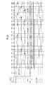
図5は、実施例1のモータ制御装置におけるクローズドループ制御時の駆動TR回路と相コイルの接続点(BEMF検知回路へのBEMF電圧入力)に現れる電圧波形を示す図である。図5において、制御の1周期は、時間TbF→時間TdH→時間TbB→時間TdLの順序であり、例えば120°通電制御タイミングでの電気角は、各々60°、120°、60°、120°の幅で合計360°の電気角で1周期を構成している。 FIG. 5 is a diagram illustrating a voltage waveform appearing at a connection point (BEMF voltage input to the BEMF detection circuit) between the drive TR circuit and the phase coil during closed-loop control in the motor control device of the first embodiment. In FIG. 5, one cycle of control is in the order of time TbF → time TdH → time TbB → time TdL. For example, the electrical angles at 120 ° energization control timing are 60 °, 120 °, 60 °, and 120 °, respectively. One period is composed of a total of 360 ° electrical angles.
時間TbFと時間TbBは、BEMFを検知する期間であり、検知相コイルに対応する駆動TR回路3の駆動オフ期間である。時間TbFがBEMFの立ち上り側、時間TbBが立ち下り側の検知期間となっている。
時間TbFと時間TbBの期間中に図5に太線で示すBEMF電圧波形と、中点電位との交差、即ちBEMFゼロクロスタイミングの検知(図5の位置Z)があり、その時点より時間Tzのタイミング(例えば、電気角で30°)を取って、転流する。立ち上り検知時は、駆動TR回路3のハイサイド側(アッパー側)の駆動制御を、立ち下り検知時は、駆動TR回路3のローサイド側(ロワ側)の駆動制御を実施する。なお、時間TdH,TdLはそれぞれ、転流によるハイサイドとローサイドのTR駆動制御期間を表す。
Time TbF and time TbB are periods in which BEMF is detected, and are driving off periods of the driving
During the period of time TbF and time TbB, there is an intersection between the BEMF voltage waveform shown by a bold line in FIG. 5 and the midpoint potential, that is, detection of BEMF zero cross timing (position Z in FIG. 5). Take (for example, 30 degrees in electrical angle) and commutate. When rising is detected, drive control on the high side (upper side) of the
この時のBEMF検知では、検知相の相コイルの駆動TR回路3は、駆動状態でなく、オープンにしている。しかし、他相のコイルは駆動状態にあるため、BEMF電位は、他相の駆動電圧の相コイル抵抗成分による分圧を中点電圧として発生することになる。例えば、コイル抵抗が同じであれば、1/2駆動電圧=1/2Vbatとなる。中点電位は、BEMF検知回路4では、比較基準電位回路7が発生させる電圧比較用基準電圧(基準電圧)に対応している。
In the BEMF detection at this time, the driving
言い換えて説明する。例えば、120°駆動制御を行う場合、BEMF検知回路4で各相のBEMFを検出し、各相にBEMFの位相のゼロクロスポイントを検出することで、各相のステータコイルの駆動タイミング、つまり転流タイミング制御する。
In other words, explain. For example, when 120 ° drive control is performed, the
そして、転流タイミングでの各相コイルの駆動は、インバータとして機能する駆動TR回路3のハーフブリッジ回路により駆動され、駆動時にPWM制御によりコイルに印加する電圧を制御することで、センサレスブラシレスモータ5の回転速度を制御する。
The drive of each phase coil at the commutation timing is driven by the half bridge circuit of the
BEMFによるゼロクロス検出は、ハーフブリッジでオフ状態のブリッジ回路のブリッジポイントに現れる電圧変化により行われる。実施例1では、スター結線による3相のセンサレスブラシレスモータ5におけるBEMFのゼロクロス検出点、つまり、ハーフブリッジのオフタイミングのブリッジ回路のブリッジ点には、コイルに印加されている電源電圧の約1/2の電位を基準として、BEMFが重畳されるため、電源電圧の約1/2の電位をゼロとし、この基準電位を重畳したBEMFの電圧がクロスするタイミングを検知することをゼロクロスとする。つまり、BEMFでゼロクロスを検知する際の閾値は電源電圧の1/2電位となる。
Zero cross detection by BEMF is performed by a voltage change appearing at a bridge point of a bridge circuit in an OFF state by a half bridge. In the first embodiment, the BEMF zero-crossing detection point in the three-phase
更に、言い換えて説明すると、例えば、センサレスブラシレスモータ5をPWM駆動する際、スイッチ素子Qu1とQv2がオンとなり、他がオフであるとする。すると、電源電圧Vbatからスイッチ素子Qu1を経て、センサレスブラシレスモータ5のU相コイル1u、V相コイル1vを経て、スイッチ素子Qv2からグランドへ向かう電流経路で電流が流れることになる。
Furthermore, in other words, for example, when the
この際に、W相コイル1Wを駆動するためのスイッチ素子Qw1,Qw2のブリッジ点は、コイル5u、コイル5vの中点接続電圧をコイル5wで検出している状態と言える。このオフ状態のブリッジ点の電圧は上記説明したように、1/2Vbatを基準に、各相コイル5u,5v,5wに発生するBEMF電圧が重畳された電圧波形が観測される。そして、このブリッジ点の電圧を基準電圧と比較すれば、ゼロクロス信号を得ることになる。実施例1では、ゼロクロス信号を制御回路2へ入力し、転流タイミングを得ることでセンサレスブラシレスモータ5を駆動制御する。
At this time, the bridge point of the switch elements Qw1 and Qw2 for driving the W-phase coil 1W can be said to be a state where the
実施例1では、BEMF検知回路4のBEMFゼロクロスタイミング検知用の基準電圧を、相コイルに供給するモータ相コイルバイアス回路6を設けている。
制御上では、全相コイルが駆動オフの全相オープン(各相コイル5u,5v,5wに発生するBEMFの中点電位がフローティングの状態)のタイミングと、各相コイル5u,5v,5wの駆動タイミングと、を交互に繰り返し、全相オープンのタイミングで回転状態検知を実施するクローズドループ制御を行っている。
In the first embodiment, a motor phase
In terms of control, all phase coils are driven off and all phases are open (the BEMF midpoint potential generated in each
回転状態検知制御は、各相コイル5u,5v,5wを駆動オフとすることで、相コイル間の接続点電位をフローティングにし、モータ相コイルバイアス回路6により、相コイル電位をBEMF検知回路4のBEMFゼロクロス検出用の基準電圧にバイアスする。これにより、検知相コイルに発生するBEMFの中点電位を、BEMF検知回路4のBEMFゼロクロス検出用の基準電圧とすることができ、BEMFが低い状態のゼロクロスずれの誤差を相対的にキャンセルする。そのため、高精度なBEMF電圧ゼロクロス検出が可能である。
In the rotation state detection control, each
詳しく述べると、センサレスブラシレスモータ5が低回転の全相オープン状態では、図6に示すように、相コイルから出力されるBEMF電圧波形は、モータ相コイルバイアス回路6でバイアスされた比較基準電圧を中心とした波形となる。つまり、BEMF電圧波形は、振幅が小さく、誤差ΔV’も小さくなるが、モータ相コイルバイアス回路6でバイアスされた比較基準電圧、すなわち、BEMFの中点電位を中心とした波形となるため、BEMF検知回路4によるBEMF電圧ゼロクロス(以後、BEMFゼロクロス)の検出が可能である。
More specifically, when the
ここで、実施例1のモータ制御装置A1のモータ相コイルバイアス回路6によるBEMF電圧波形について説明を加える。図7は、実施例1のモータ制御装置における回転状態検知時に回転するセンサレスブラシレスモータ5の各相コイル5u,5v,5wに現れる、電気角度に対するBEMF電圧波形を示す図である。
Here, the BEMF voltage waveform by the motor phase
実施例1では、センサレスブラシレスモータ5がスター結線であるのに対し、それぞれの相コイル5u,5v,5wに、接続位置50u,50v,50wでモータ相コイルバイアス回路6と接続する。そして、抵抗R4〜R6を介してそれぞれ3点からバイアスされる。この際、駆動信号はオフで、センサレスブラシレスモータ5のロータは、極低回転数で回転するものとする。この状態で得られるBEMF電圧波形は、図7に波形特性線100u,100v,100wに示すように、高回転時に駆動に用いられないコイルにより検知されるBEMF電圧波形と同等の電圧波形を得ることができる。
In the first embodiment, the
[BEMFゼロクロス間の時間計測作用]
モータ回転(起動)制御は、回転起動位相と回転状態検知制御を開始した直後に検知した位相、又は、1つのBEMFゼロクロス検出を挟んだ位相関係と、少なくとも2つの連続するBEMFゼロクロス検出から、ゼロクロス間の時間計測値と、最終ゼロクロス位置(タイミング)より、回転方向,電気角と転流制御位相,転流タイミングの確定を行う制御である。
[Time measurement action between BEMF zero crossings]
The motor rotation (startup) control is based on the phase detected immediately after starting the rotation start phase and the rotation state detection control, or the phase relationship sandwiching one BEMF zero cross detection and at least two consecutive BEMF zero cross detections. In this control, the rotational direction, the electrical angle, the commutation control phase, and the commutation timing are determined based on the time measurement value between them and the final zero cross position (timing).
前記BEMFゼロクロス間の時間計測としては、例えば、図8に示すように、
1)同相の1周期(BEMFの立ち上がり又は立下り間=電気角360°毎)
2)半周期(BEMFの立ち上がりから立下り又はその逆の間=電気角180°毎)
3)相間に渡るBEMFの立ち上がり又は立下り間(=電気角120°毎)
4)相間に渡るBEMFの立ち上がりから立下り又はその逆の間(=電気角60°毎)
等、計測方法がある。
実施例1では、計測に要する時間が短いという理由により、上記4)の相間に渡るBEMFの立下りから立ち上がり間で計測としている。なお、BEMFゼロクロス間の時間計測に関しては、実施例2〜5についても同様に電気角60°毎の計測を採用している。
As the time measurement between the BEMF zero crosses, for example, as shown in FIG.
1) One cycle of in-phase (Between rising and falling BEMF = electrical angle every 360 °)
2) Half cycle (Between rising and falling BEMF or vice versa = every 180 ° electrical angle)
3) Between the rise and fall of BEMF between phases (= Electrical angle every 120 °)
4) Between the rise and fall of BEMF across the phase or vice versa (= Electrical angle every 60 °)
There are measurement methods.
In the first embodiment, the measurement is performed between the falling edge and the rising edge of the BEMF over the phase 4) because the time required for the measurement is short. In addition, regarding the time measurement between BEMF zero crosses, the measurement for each electrical angle of 60 ° is similarly adopted in Examples 2 to 5.
以下、図9のタイミングチャートを用いて、実施例1のBEMFゼロクロス間の時間計測作用を説明する。
位相DでU相コイル5uから検知するBEMFゼロクロス(立下り)と、位相EでW相コイル5wから検知するBEMFゼロクロス(立ち上がり)間の時間T1を計測する。この計測で、電気角60°当たりの時間T1のモータ回転状態データが得られたため、制御は、回転状態検知制御の次の制御であるモータ相コイル駆動(転流)を実施することになる。
実施例1のモータ相コイル駆動は、公知の120°通電制御であるため、W相コイル5wのゼロクロス検出タイミングより、電気角30°、即ちT1/2=t1後に、位相Fに転流制御し、次に位相Aに転流制御することになる。
Hereinafter, the time measurement operation between the BEMF zero crosses according to the first embodiment will be described with reference to the timing chart of FIG.
A time T1 between a BEMF zero cross (falling) detected from the
Since the motor phase coil drive of the first embodiment is a known 120 ° energization control, the commutation control is performed to the phase F after an electrical angle of 30 °, that is, T1 / 2 = t1 from the zero cross detection timing of the
制御位相Fは、U相がローサイドTR/ONで,W相がハイサイドTR/ONの位相であり、制御位相AはV相がローサイドTR/ONで,W相がハイサイドTR/ONの位相で、転流制御時の相コイル通電PWM/Dutyはモータ回転数を上昇させるため、起動時の通電PWM/Dutyより高く(通電時間を長く)設定され、相コイルを駆動する。なお、前記制御位相FとAは、各々T1時間(電気角60°分)通電されるが、前記PWM/Dutyを高く設定し、加速率が所定(既知)な場合は、所定の比率でT1時間を短く設定することも可能である。
The control phase F is the phase where the U phase is the low side TR / ON and the W phase is the high side TR / ON. The control phase A is the phase where the V phase is the low side TR / ON and the W phase is the high side TR / ON. Therefore, the phase coil energization PWM / Duty at the time of commutation control is set higher (longer energization time) than the energization PWM / Duty at the time of startup to drive the phase coil. The control phases F and A are energized for T1 time (
[実施例1のモータ起動制御の特徴]
本発明は、比較例の問題点に鑑み、BEMFゼロクロス検出で回転制御するセンサレスブラシレスモータにおいて、少なくとも中性点電圧を比較基準電圧として利用できない場合でも、簡単な回路構成で回転起動を含む極低回転数からのBEM位相とゼロクロス検出を可能とした。すなわち、モータ非通電時の停止を含む位相(ロータ位置)状態に無関係に、極低回転数(例えば、30rpm以下)から、BEMFゼロクロス検出に基づく回転位相に同期した回転起動制御(クローズドループ制御)が可能になり、モータ回転起動応答性が速くかつ静かなモータを、安価な回路と制御方法で可能にしたことを特徴としている。
[Characteristics of motor start control of embodiment 1]
In view of the problems of the comparative example, the present invention is a sensorless brushless motor that performs rotation control with BEMF zero-cross detection, and even when at least a neutral point voltage cannot be used as a comparison reference voltage, it is extremely low including rotation start-up with a simple circuit configuration. BEM phase and zero-crossing detection from rotation speed is possible. In other words, regardless of the phase (rotor position) state including the stop when the motor is not energized, the rotation start control (closed loop control) synchronized with the rotation phase based on the BEMF zero cross detection from the extremely low rotation speed (for example, 30 rpm or less) The motor rotation start response is quick and quiet, and it is possible to use a cheap circuit and control method.
実施例1では、センサレスブラシレスモータ5を非通電の停止状態から回転起動する場合は、任意の位相に短時間(モータが回転開始する時間)初期通電し、その直後に回転状態検知を設け、極低回転数からモータの位相(ロータ位置)を検知する。そして、回転起動位相を基本として、回転状態検知で検出した位相の関係より、正回転(図9),停止(図10),逆回転(図11)の状態を判断し、判断に応じた処理制御後位相に転流(対応した相コイルに通電切り替え)制御し、転流制御中にBEMFのゼロクロス検出による位相転流ができない場合には再度、回転状態検知と転流制御を繰り返し実施する。
In Example 1, when the
このように、モータの非通電位相に関係なく、起動時からクローズドループ制御でモータの回転位相(電気角の位置)に同期したモータ駆動を可能にしたため、異音,過電流を低減し、脱調の無い、センサレスブラシレスモータ5の起動を実現することができる。
In this way, the motor drive synchronized with the motor rotation phase (electrical angle position) is enabled by the closed-loop control from the start-up regardless of the motor de-energization phase. The
更に、起動時のモータ非通電停止位相の位置確定制御をする必要が無く、回転起動のための相コイル駆動から制御を開始し、クロ−ズドループ制御となる。このため、駆動位相がモータの回転位相に同期していることより、起動時からモータ駆動電流を増加(駆動デューティを増加)させることが可能となり、応答時間の早いモータ起動を実現することができる。 Further, there is no need to perform position determination control of the motor de-energization stop phase at the time of starting, and control is started from phase coil driving for rotation starting, and closed loop control is performed. For this reason, since the drive phase is synchronized with the rotational phase of the motor, it is possible to increase the motor drive current (increase the drive duty) from the time of startup, and to realize motor startup with a quick response time. .
加えて、回転起動時の回転状態検知制御で任意回数の停止状態を継続検出した場合、モータロックを確実に検知し、通電解除の制御をすることで、モータロック時の過電流を防止しフェイルセーフ動作を実現できる(図2)。 In addition, when the rotation state detection control at the time of rotation start is continuously detected any number of times, the motor lock is reliably detected and the energization release control is performed to prevent overcurrent at the time of motor lock and fail. Safe operation can be realized (FIG. 2).
図9〜図11に示す具体例では、回転起動時位相でのモータ相コイルへの通電は、モータ慣性質量と負荷に応じた必要最低限のPWM/Dutyと時間で駆動し、回転起動時のモータの回転数を抑えるようにしてあり、図11では、回転起動直後の回転状態検知で回転方向が、逆転状態であった場合に、次の制御で回転方向を正転にするための駆動を容易にできるようにしてある。 In the specific examples shown in FIGS. 9 to 11, energization of the motor phase coil in the rotation start phase is driven by the minimum necessary PWM / Duty and time according to the motor inertia mass and the load, In FIG. 11, when the rotation direction is detected in the rotation state immediately after the start of rotation and the rotation direction is the reverse rotation state, the drive for making the rotation direction forward is performed in the next control. Easy to do.
上記図9〜図11は、実施例1での制御具体例を示したタイミングチャートである。
図9〜図11の最上部には、「モータ位相の位置」を示し、U相のBEMFが上昇するゼロクロス位置を0°とした電気角360°を、60°毎に分割した電気角位置(°)を数値であらわし、各相コイルの駆動制御の位置(位相)をA〜Fによりあらわしている。
FIGS. 9 to 11 are timing charts showing specific examples of control in the first embodiment.
The top of FIGS. 9 to 11 shows the “motor phase position”. The electrical angle position obtained by dividing the
その下に、各相コイル制御位相に対応する「駆動TR回路の状態」を示し、そのタイミングに重ねて、駆動TRのOFFラインをゼロクロス電位(回転状態検知制御時は、BEMF検知回路の比較基準電圧で、その他の時は、モータ相コイルによる中性点電位=BEMFの中点電位)として、各位相タイミングに対応した、各相コイルに発生するBEMF電圧波形が破線で示してある。なお、BEMF電圧波形のゼロクロス点が○印で表され、制御上の検知点は○とZ記号で示してあり、ゼロクロス間の周期はT1〜T8で示してある。 Below that, the “state of the driving TR circuit” corresponding to each phase coil control phase is shown, and the OFF line of the driving TR is set to the zero cross potential (at the time of rotation state detection control, the comparison reference of the BEMF detection circuit), overlapping that timing. In other cases, the BEMF voltage waveform generated in each phase coil corresponding to each phase timing is indicated by a broken line as neutral point potential by the motor phase coil = BEMF midpoint potential). Note that the zero cross point of the BEMF voltage waveform is indicated by ◯, the control detection points are indicated by ◯ and Z symbols, and the period between zero crosses is indicated by T1 to T8.
その下に、「制御のフェーズ」を制御内容と共に示している。各フェーズと制御内容を説明する。「フェーズI」は、モータ停止状態を示す相で、各相コイルへの通電はない状態である。「フェーズII」は、回転起動のため、任意に決めた所定の相コイルに通電する相である。通電する相コイルの位相にあわせた、駆動TR回路3のON/OFF状態が示してある。「フェーズIII」は、全相オープン(回転状態検知)と設定デューティ駆動(モータ相コイル駆動)を交互に繰り返すBEMF検知によるクローズドループ制御を行う相である。「フェーズIV」は、位相合わせ状態で設定デューティ駆動をする120°通電制御を行う相である。
Below that, the “control phase” is shown together with the control contents. Each phase and control contents will be described. "Phase I" is a phase indicating a motor stop state, and is a state where no current is supplied to each phase coil. “Phase II” is a phase in which a predetermined phase coil that is arbitrarily determined is energized to start rotation. The ON / OFF state of the
更にその下に、U相、V相、W相の「BEMF検知信号」を示し、BEMF検知回路4からのゼロクロス信号が入力される制御回路2でのフィルタリング処理後の各相のBEMFゼロクロス検出状態を実線で示してあり、破線は検知不定の状態を示す。なお、フィルタリング処理は、デジタルフィルタにより、PWM信号等によるノイズパルスと転流後の回生電流による発生波形の除去が含まれる。又、ゼロクロス検出による位相反転後の前記検知不定状態の期間は、次のゼロクロス検出による反転が検知されるまで、制御回路内で状態が保持される。
Below that, “BEMF detection signals” for U phase, V phase, and W phase are shown, and the BEMF zero cross detection state of each phase after filtering processing in the
以下、図2及び図9〜図11に基づき、正回転起動例(図9)、停止起動例(図10)、逆回転起動例(図11)を説明する。 Hereinafter, a forward rotation start example (FIG. 9), a stop start example (FIG. 10), and a reverse rotation start example (FIG. 11) will be described based on FIG. 2 and FIGS.
[起動出力により正回転した場合のモータ起動制御作用]
非通電停止からのモータ起動時、図2のフローチャートにおいて、ステップS101→ステップS102の回転状態検知へと進み、ステップS102では詳細ステップであるステップS102a→ステップS102bへと進む。ステップS101では、センサレスブラシレスモータ5のモータ慣性質量と負荷に応じた必要最低限の時間と低デューティ駆動により初期回転起動するオープンループ制御が行われる。次のステップS102aでは、センサレスブラシレスモータ5の各相コイル5u,5v,5wの全てをオープンにする全相オープン制御を行い、全相オープン中における逆起電力と比較基準電位のゼロクロス信号に基づき、回転位相と転流位相と転流タイミングを監視し、これら回転位相・転流位相・転流タイミングの全てを確定させる。次のステップS102bでは、センサレスブラシレスモータ5のモータ回転状態の判定を行う。
[Motor start control action when rotating forward by start output]
At the time of starting the motor from the non-energized stop, in the flowchart of FIG. 2, the process proceeds from step S101 to step S102, and the process proceeds from step S102a to step S102b, which are detailed steps. In step S101, open loop control is performed in which initial rotation is started by a minimum required time corresponding to the motor inertia mass and load of the
そして、モータ回転状態の判定により、判定結果が正回転状態であると、ステップS102bからステップS103→ステップS104→ステップS105へ進み、ステップS105でBEMFゼロクロス検出有りと判断される限り、ステップS103→ステップS104→ステップS105へと進む流れが繰り返される。ステップS103では、センサレスブラシレスモータ5の各相コイル5u,5v,5wへの転流制御により、センサレスブラシレスモータ5を正回転させる回転駆動制御が行われる。ステップS104では、BEMFゼロクロス検出に基づき、転流位相と転流タイミングが確定される。
If the result of the motor rotation state is determined to be the normal rotation state, the process proceeds from step S102b to step S103 → step S104 → step S105, and step S103 → step is performed as long as it is determined that BEMF zero cross detection is detected in step S105. The flow from S104 to step S105 is repeated. In step S103, rotational drive control for rotating the
図9は、実施例1のモータ制御装置A1で非通電停止からのモータ起動時に起動出力により正回転した場合の駆動TR回路の状態とBEMF検知信号の特性を示すタイミングチャートである。以下、図9に基づいて、起動出力により正回転した場合のモータ起動制御作用を説明する。 FIG. 9 is a timing chart showing the state of the drive TR circuit and the characteristics of the BEMF detection signal when the motor control device A1 according to the first embodiment is rotated forward by the start output when the motor is started from the non-energized stop. Hereinafter, based on FIG. 9, the motor start control operation when the motor rotates forward by the start output will be described.
図9の制御例は、モータ停止位置位相から、起動制御位相へ正転の場合で、センサレスブラシレスモータ5が、各相コイル非通電であり、位相Bで停止状態の「フェーズI」から、回転起動の「フェーズII」に移行し、モータ相コイルへの通電位相を、U相がハイサイドTR/ONで,W相がローサイドTR/ONの位相Cの通電状態で開始とした場合で、C相駆動(通電)時間は、駆動PWM/Dutyに応じた、例えば、数十msecから数百msecの回転起動(開始)に必要な所定時間駆動する。
The control example of FIG. 9 is a case of normal rotation from the motor stop position phase to the start control phase. The
前記制御で、センサレスブラシレスモータ5は正回転を開始し、各相コイルでBEMFが発生するため、制御は次の「フェーズIII」に移行する。
「フェーズIII」以降は、モータ回転状態(モータ電気角と回転速度)を、BEMF電圧ゼロクロス検出により確定し、制御位相を決めて転流制御するクローズドループ制御となる。
このため、「フェーズIII」の最初の制御は、モータの回転状態を検知する、即ち、BEMFゼロクロスを検出する回転状態検知制御を実施する。
With the above control, the
After “Phase III”, the motor rotation state (motor electrical angle and rotation speed) is determined by the BEMF voltage zero cross detection, and the control phase is determined to perform closed loop control for commutation control.
For this reason, in the first control of “Phase III”, the rotation state detection control for detecting the rotation state of the motor, that is, detecting the BEMF zero cross is performed.
BEMF検知は、モータロータの角速度と比例相関をもつBEMFを、電圧比較器を用い、BEMF電圧波形が、BEMF電圧波形の中点(中心)電位を横切る時点をゼロクロスとし、以上と以下の2値にて検知しているため、BEMF電圧波形の中点電位と電圧比較器の比較基準電位の一致精度でゼロクロス検出できる最小BEMF電圧即ち最低回転数が決まる。
このため、BEMF電圧波形の中点電位に近い、スター結線での全てのモータ相コイルを接続した中性点の電位を用いた場合を除き、擬似中点電圧を用いてBEMF検知回路の比較基準電圧とする。実施例1のBEMFゼロクロス検出回路構成による制御では、電圧的に誤差が小さく、起動時を含む低回転時にBEMFゼロクロス検出ができる。
BEMF detection uses BEMF, which has a proportional correlation with the angular velocity of the motor rotor, using a voltage comparator. When the BEMF voltage waveform crosses the midpoint (center) potential of the BEMF voltage waveform, the zero crossing is obtained. Therefore, the minimum BEMF voltage, that is, the minimum number of revolutions that can be detected by the zero crossing is determined by the matching accuracy between the midpoint potential of the BEMF voltage waveform and the comparison reference potential of the voltage comparator.
For this reason, except for the case where the neutral point potential connected to all motor phase coils in the star connection, which is close to the midpoint potential of the BEMF voltage waveform, is used, the comparison reference for the BEMF detection circuit using the pseudo midpoint voltage Voltage. In the control by the BEMF zero-cross detection circuit configuration of the first embodiment, the voltage error is small, and BEMF zero-cross detection can be performed at low revolutions including at the time of startup.
以降、前述の回転状態検知制御とモータ相コイル駆動の制御を繰り返し、センサレスブラシレスモータ5の回転数を上昇させ、回転数の上昇とともにBEMF電圧発生値も大きくなっていき、公知のBEMFゼロクロスが可能な電圧値に到達する。
Thereafter, the rotation state detection control and the motor phase coil drive control described above are repeated to increase the rotation speed of the
図9のタイミングチャートでは、T4計測とt4による制御位相Fへの転流制御まで継続され、BEMF電圧値も大きくなっており、制御位相Fへの転流直後に公知のBEMFゼロクロス検出が、V相コイルからのBEMFゼロクロス検出により発生し、「フェーズIII」による回転状態検知制御は終了する。よって、それ以降、公知のBEMFゼロクロス検出による120°通電制御である「フェーズIV」に移行する。 In the timing chart of FIG. 9, the TMF measurement and the commutation control to the control phase F by t4 are continued, the BEMF voltage value is increased, and the known BEMF zero-cross detection immediately after the commutation to the control phase F is V It is generated by detecting BEMF zero cross from the phase coil, and the rotation state detection control by “Phase III” ends. Therefore, thereafter, the process proceeds to “Phase IV”, which is 120 ° energization control by the known BEMF zero cross detection.
[回転起動制御で停止した場合のモータ起動制御作用]
非通電停止からのモータ起動時、図2のフローチャートにおいて、ステップS101→ステップS102a→ステップS102bへと進む。ステップS101では、センサレスブラシレスモータ5のモータ慣性質量と負荷に応じた必要最低限の時間と低デューティ駆動により初期回転起動するオープンループ制御が行われる。次のステップS102aでは、センサレスブラシレスモータ5の各相コイル5u,5v,5wの全てをオープンにする全相オープン制御を行い、全相オープン中における逆起電力と比較基準電位のゼロクロス信号に基づき、回転位相と転流位相と転流タイミングを監視し、これら回転位相・転流位相・転流タイミングの全てを確定させる。次のステップS102bでは、センサレスブラシレスモータ5のモータ回転状態の判定を行う。
[Motor start control action when stopped by rotation start control]
When the motor is started after deenergization is stopped, the process proceeds from step S101 to step S102a to step S102b in the flowchart of FIG. In step S101, open loop control is performed in which initial rotation is started by a minimum required time corresponding to the motor inertia mass and load of the
そして、モータ回転状態の判定により、判定結果が停止状態であると、ステップS102bからステップS107へ進み、ステップS107では、停止判定回数<Nであると判断に基づき、ステップS108へ進む。ステップS108では、停止状態のセンサレスブラシレスモータ5の各相コイル5u,5v,5wに対し、正回転方向に位相を進める転流制御へ移行し、所定時間だけ回転再起動を行い、ステップS102aへ戻る。そして、ステップS102aからステップS102bへ進み、ステップS102bにて正回転状態と判定されると、ステップS102bからステップS103→ステップS104→ステップS105へ進み、ステップS105でBEMFゼロクロス検出有りと判断される限り、ステップS103→ステップS104→ステップS105へと進む流れが繰り返される。ステップS103では、センサレスブラシレスモータ5の各相コイル5u,5v,5wへの転流制御により、センサレスブラシレスモータ5を正回転させる回転駆動制御が行われる。
If the result of the determination is that the motor is in a stopped state, the process proceeds from step S102b to step S107. In step S107, the process proceeds to step S108 based on the determination that the number of stop determinations <N. In step S108, the
図10は、実施例1のモータ制御装置A1で非通電停止からのモータ起動時に停止位相と起動位相が同じで回転起動制御により停止した場合の駆動TR回路の状態とBEMF検知信号の特性を示すタイミングチャートである。以下、図10に基づいて、回転起動制御で停止した場合のモータ起動制御作用を説明する。 FIG. 10 shows the state of the drive TR circuit and the characteristics of the BEMF detection signal when the motor control device A1 of the first embodiment has the same stop phase and start phase when the motor is started from the non-energized stop and is stopped by the rotation start control. It is a timing chart. Hereinafter, based on FIG. 10, the motor activation control action when stopped by the rotation activation control will be described.
図10の制御例は、モータ停止位置位相と、起動制御位相が同じで回転起動でセンサレスブラシレスモータ5が回転せず停止の場合で、各相コイル非通電であり、位相Cで停止状態の「フェーズI」から、回転起動の「フェーズII」に移行し、モータ相コイルへの通電位相を、図9制御例と同様に、位相Cの通電状態で開始するとした場合であるが、位相が同じため、図9のようにモータが回転開始せず、BEMF電圧も発生しない。
The control example of FIG. 10 is a case where the motor stop position phase is the same as the start control phase, the rotation of the
モータ停止の場合、回転起動後の回転状態検知制御においても、BEMFゼロクロスを検知できないため、所定時間(例えば、電気角60°〜120°相当の数十msec〜数百msec程度)経過後に、回転状態検知制御を同位相停止判断で終了し、次の制御である同位相起動(再回転起動)制御に移行する。所定時間としては、例えば、4極6励磁で30rpm起動の場合(1回転2秒の微速)であって、回転状態検知に120°の電気角を要する場合には、333msec{=(30/60)×2×(120/360)}となる。
When the motor is stopped, the BEMF zero cross cannot be detected even in the rotation state detection control after the rotation is started. Therefore, the motor rotates after a predetermined time (for example, about several tens of milliseconds to several hundreds of milliseconds corresponding to an electrical angle of 60 ° to 120 °). The state detection control is terminated by the in-phase stop determination, and the next control is in-phase start (re-rotation start) control. The predetermined time is, for example, 333 msec {= (30/60) in the case of starting at 30 rpm with 4 poles and 6 excitations (slow speed of 1
次の同位相起動(再回転起動)では、回転起動のための通電制御位相を、最初の回転起動の制御位相Cに対し1つ位相を進め、制御位相Dとして、正回転への転流制御に移行する。これ以降、位相は異なるが、制御としては図9と同様となる。なお、同位相時に進める次の駆動位相は、同位相から電気角で180°未満であれば任意に決められる。 In the next in-phase activation (re-rotation activation), the energization control phase for rotation activation is advanced by one phase with respect to the control phase C of the first rotation activation, and commutation control to forward rotation is performed as the control phase D. Migrate to Thereafter, the phase is different, but the control is the same as in FIG. The next drive phase advanced at the same phase can be arbitrarily determined as long as the electrical angle is less than 180 ° from the same phase.
[モータロック判定制御作用]
非通電停止からのモータ起動時、図2のフローチャートにおいて、ステップS101→ステップS102a→ステップS102bへと進み、ステップS102bでのモータ回転状態が停止状態であると判定されると、ステップS102bからステップS107へ進み、ステップS107では、停止判定回数(位相を進めた回数)<Nであると判断に基づき、ステップS108へ進む。ステップS108では、停止状態のセンサレスブラシレスモータ5の各相コイル5u,5v,5wに対し、正回転方向に位相を進める転流制御へ移行し、所定時間だけ回転再起動を行い、ステップS102aへ戻る。
[Motor lock determination control action]
When the motor is started from the non-energized stop, the process proceeds from step S101 to step S102a to step S102b in the flowchart of FIG. 2, and if it is determined that the motor rotation state in step S102b is the stop state, step S102b to step S107 are performed. In step S107, the process proceeds to step S108 based on the determination that the number of stop determinations (number of times the phase has been advanced) <N. In step S108, the
そして、次にステップS102aからステップS102bへ進んでも、ステップS102bにて停止状態と判定されると、ステップS102bからステップS107へ進み、ステップS107では、停止判定回数(位相を進めた回数)<Nであると判断に基づき、ステップS102aへ戻る。このように、ステップS102a→ステップS102b→ステップS107→ステップS108へと進む流れが繰り返され、この繰り返し回数が予め定めた設定回数N以上になると、ステップS107からステップS109へ進み、ステップS109では、モータロックフェイルであると判断され、モータ通電停止によるフェイルセーフ動作へ移行する。 And even if it progresses to step S102b from step S102a next, if it determines with a stop state in step S102b, it will progress to step S107 from step S102b, and in step S107, the number of times of stop determination (number of times the phase has been advanced) <N Based on the determination that there is, the process returns to step S102a. In this way, the flow of going from step S102a → step S102b → step S107 → step S108 is repeated, and when the number of repetitions is equal to or greater than a predetermined number N, the process proceeds from step S107 to step S109. It is determined that a lock failure has occurred, and a transition is made to a fail-safe operation due to the motor energization stop.
このモータロック判定制御は、上記の停止起動例の続きで説明すると、制御位相Dでの再起動でも停止判断となり、この場合、更に位相を1つ進めて制御位相Eで再々起動を行うが再々度停止判断となり、この様に停止判断による位相を進角させて起動し直しの制御を連続して設定回数(N)繰り返した後、モータロックと判定するものである。 This motor lock determination control will be described as a continuation of the above stop / start example. Even if restart is performed at the control phase D, stop determination is also performed. In this case, the phase is further advanced by one and restarted at the control phase E. In this way, it is determined that the motor is locked after the control for restarting by advancing the phase based on the stop determination is repeated for a set number of times (N).
更には、この制御において、モータロックの要因として、例えば、軸受けの静止摩擦増加によるものを想定し、停止判定後の進角位相での駆動トルクを上昇させるため、同時に駆動デューティを増加させていくことも可能である。この制御で、回転開始した駆動デューティを記憶手段(EEPROM等)に記憶し、次回起動時に(必要に応じて補正して)使用するという学習機能付きの制御とすることで、起動時間を早くすることができる。 Further, in this control, for example, the cause of motor lock is assumed to be due to an increase in static friction of the bearing, and the drive duty is increased at the same time in order to increase the drive torque in the advance phase after the stop determination. It is also possible. With this control, the drive duty that has begun to rotate is stored in storage means (EEPROM, etc.), and the start-up time is shortened by the control with a learning function that is used at the next start-up (corrected as necessary). be able to.
[起動出力により逆回転した場合のモータ起動制御作用]
非通電停止からのモータ起動時、図2のフローチャートにおいて、ステップS101→ステップS102a→ステップS102bへと進み、ステップS102bでのモータ回転状態が逆回転状態であると判定されると、ステップS102bからステップS106へ進み、ステップS106では、逆回転状態のセンサレスブラシレスモータ5の各相コイル5u,5v,5wに対し、正回転となる位相による回転方向修正の転流制御へ移行し、モータ停止を介することなく、所定時間だけ回転再起動を行い、ステップS102aへ戻る。
[Motor start control action when rotating reversely by start output]
When the motor is started from the non-energized stop, the process proceeds from step S101 to step S102a to step S102b in the flowchart of FIG. 2, and if it is determined that the motor rotation state in step S102b is the reverse rotation state, the process proceeds from step S102b to step S102b. Proceeding to S106, in Step S106, the control is shifted to the commutation control for correcting the rotational direction by the phase of the normal rotation for each
そして、ステップS102aからステップS102bへ進み、ステップS102bにて正回転状態と判定されると、ステップS102bからステップS103→ステップS104→ステップS105へ進み、ステップS105でBEMFゼロクロス検出有りと判断される限り、ステップS103→ステップS104→ステップS105へと進む流れが繰り返される。ステップS103では、センサレスブラシレスモータ5の各相コイル5u,5v,5wへの転流制御により、センサレスブラシレスモータ5を正回転させる回転駆動制御が行われる。
Then, the process proceeds from step S102a to step S102b, and when it is determined in step S102b that it is in the normal rotation state, the process proceeds from step S102b to step S103 → step S104 → step S105, as long as it is determined that there is BEMF zero cross detection in step S105 The flow from step S103 to step S104 to step S105 is repeated. In step S103, rotational drive control for rotating the
図11は、実施例1のモータ制御装置A1で非通電停止からのモータ起動時に停止位相と起動位相が逆回転の関係になり回転起動制御により逆回転した場合の駆動TR回路の状態とBEMF検知信号の特性を示すタイミングチャートである。以下、図11に基づいて、回転起動制御で逆回転した場合のモータ起動制御作用を説明する。 FIG. 11 shows the state of the driving TR circuit and the BEMF detection when the stop phase and the start phase are in a reverse rotation relationship when the motor is started from the non-energized stop in the motor control device A1 of the first embodiment and the reverse rotation is performed by the rotation start control. It is a timing chart which shows the characteristic of a signal. Hereinafter, based on FIG. 11, the motor activation control operation in the case of reverse rotation by the rotation activation control will be described.
図11の逆回転起動制御例は、モータ停止位置位相と、起動制御位相が逆回転の関係になり、回転起動でセンサレスブラシレスモータ5が逆回転した場合で、各相コイル非通電で、位相Dで停止状態の「フェーズI」から、回転起動の「フェーズII」に移行し、モータ相コイルへの通電位相を、図9の制御例と同様に、位相Cの通電状態で開始するとした場合であるが、通電位相が正回転方向に逆のため、センサレスブラシレスモータ5が逆回転し、BEMF電圧も逆回転位相で発生している。
The reverse rotation start control example of FIG. 11 is a case where the motor stop position phase and the start control phase are in a reverse rotation relationship, and the
このため、回転起動後の回転状態検知制御においてBEMFゼロクロス検出は、図11のタイミングチャートに示すように、位相BでW相コイルから検知するBEMFゼロクロス検出(立上り)と、位相AでU相コイルから検知するBEMFゼロクロス検出(立ち下り)間の時間T1を計測するため、正回転位相変化のC⇒D⇒Eに対し、C⇒B⇒Aの逆回転状態と判定する。 For this reason, in the rotational state detection control after the rotation is started, BEMF zero cross detection is performed by detecting BEMF zero cross (rising) detected from the W phase coil at phase B and U phase coil at phase A as shown in the timing chart of FIG. In order to measure the time T1 between the BEMF zero cross detection (falling) detected from 1), it is determined that the reverse rotation state of C.fwdarw.B.fwdarw.A with respect to C.fwdarw.D.fwdarw.E of the forward rotation phase change.
回転起動後の回転状態検知制御において、逆回転を検知した場合、正回転にモータ回転方向を修正する、回転再起動制御を行う。
回転再起動制御は、実施例1において、最後に検知した位相Aを基点に、電気角30°に相当するt1後に位相Aに対して正回転位相となる、制御位相Bに転流させる。
In the rotation state detection control after rotation start, when reverse rotation is detected, rotation restart control is performed to correct the motor rotation direction to forward rotation.
In the rotation restart control, in the first embodiment, the phase A detected last is commutated to a control phase B that becomes a positive rotation phase with respect to the phase A after t1 corresponding to an electrical angle of 30 °.
又、起動時の回転状態検知で回転速度が大きい場合(例えば、モータ慣性質量が大きい場合等)であって、回転を反転させるための時間が必要な場合には、上記制御位相Bに転流する前に、制御位相Aに転流させても良く、滑らかに回転を反転させるための転流位相,駆動デューティの条件は、センサレスブラシレスモータ5の性能と対応する負荷により設定し、制御回路2のROM等の記憶手段に記憶させばよい。以降の制御については、位相は異なるものの、図9の制御と同様である。
In addition, when the rotational speed is high in the detection of the rotational state at the time of start-up (for example, when the motor inertia mass is large) and the time for reversing the rotation is necessary, the commutation to the control phase B is performed. The
上記起動時に逆回転した場合の制御は、正回転の場合と同様に、回転状態検知制御において、BEMFゼロクロス検出による回転方向と回転速度に基づいて、正回転にモータ回転方向を修正する制御のため、通電位相とタイミングが正確に制御できる。 The control in the case of reverse rotation at the time of start-up is for the control to correct the motor rotation direction to the normal rotation based on the rotation direction and the rotation speed by the BEMF zero cross detection in the rotation state detection control as in the case of the normal rotation. The energization phase and timing can be accurately controlled.
次に、効果を説明する。
実施例1のモータ制御装置A1にあっては、下記に列挙する効果を得ることができる。
Next, the effect will be described.
In the motor control device A1 according to the first embodiment, the effects listed below can be obtained.
(1) センサレスブラシレスモータ5と、制御回路2と、駆動トランジスタ回路(駆動TR回路3)と、逆起電力検知回路(BEMF検知回路4)と、を備え、前記センサレスブラシレスモータ5の各相コイル5u,5v,5wにて発生する逆起電力の電圧ゼロクロス検出に基づいてモータ回転位置情報を取得し、前記モータ回転位置情報を用いた各相コイル5u,5v,5wへの転流制御により回転駆動制御を行うモータ制御装置A1において、前記逆起電力検知回路(BEMF検知回路4)の比較基準電位を発生する比較基準電位回路7と、前記比較基準電位を前記センサレスブラシレスモータ5の各相コイル5u,5v,5wに供給するモータ相コイルバイアス回路6と、を設け、前記制御回路2は、モータ起動時、前記各相コイル5u,5v,5wの全てをオープンにする全相オープンと設定デューティ駆動とを繰り返すクローズドループ制御を行い、全相オープン中における逆起電力と比較基準電位の電圧ゼロクロス検出に基づき、前記センサレスブラシレスモータ5が正回転・停止・逆回転のうち何れの状態であるかの回転状態検知を実行し、回転状態検知による判定結果に応じ、前記センサレスブラシレスモータ5が正回転となる位相による転流制御へ移行するモータ起動制御手段(図2)を有する。
このため、モータ起動時、応答良くモータ回転駆動制御を開始することができると共に、非同期制御が継続することによる異音,回転脱調,停止,過電流等を回避あるいは低減できる。
(1) A
For this reason, motor rotation drive control can be started with good response when the motor is started, and abnormal noise, rotational step-out, stop, overcurrent, and the like due to continuing asynchronous control can be avoided or reduced.
(2) 前記モータ起動制御手段(図2)は、回転状態検知による判定結果が逆回転判定であるとき(ステップS102bで逆回転判定時)、モータ停止制御を介することなく、前記センサレスブラシレスモータ5が正回転となる位相による回転方向修正の転流制御へ移行する(ステップS106)。
このため、上記(1)の効果に加え、モータ起動開始域で逆回転状態であっても、応答性の良いモータ起動を実現することができる。
(2) The motor activation control means (FIG. 2) determines that the
For this reason, in addition to the effect of (1) above, it is possible to realize motor activation with good responsiveness even in the reverse rotation state in the motor activation start range.
(3) 前記モータ起動制御手段(図2)は、回転状態検知による判定結果が停止判定であるとき(ステップS102bで停止判定時)、前記センサレスブラシレスモータ5の回転を促すように位相を進める転流制御へ移行し(ステップS108)、モータ再起動を促す転流制御を実行したにもかかわらず判定結果が停止判定である経験を継続するとモータロックフェイルであると判断し(ステップS107で、停止判定回数(位相を進めた回数)>N)、フェイルセーフ動作へ移行する(ステップS109)。
このため、上記(1),(2)の効果に加え、モータ起動制御中に実行される回転状態検知での停止判定を利用し、モータ起動ロックを確実に判定し、速やかにフェイルセーフ動作へ移行することができる。
(3) The motor activation control means (FIG. 2) performs a phase advance so as to promote the rotation of the
For this reason, in addition to the effects of (1) and (2) above, the stop determination at the rotation state detection executed during the motor start control is used to reliably determine the motor start lock, and promptly go to fail safe operation. Can be migrated.
(4) 前記モータ起動制御手段(図2)は、回転状態検知の際、回転位相・転流位相・転流タイミングが確定した後(ステップS102a)、前記センサレスブラシレスモータ5が正回転・停止・逆回転の何れの状態であるかのモータ回転状態の判定を行う(ステップS102b)。
このため、上記(1)〜(3)の効果に加え、センサレスブラシレスモータ5が正回転・停止・逆回転の何れの状態であるかのモータ回転状態の判定を精度良く行うことができる。
(4) When the rotational state, commutation phase, and commutation timing are determined (step S102a), the motor start control unit (FIG. 2) detects that the
For this reason, in addition to the effects (1) to (3), it is possible to accurately determine whether the
(5) 前記モータ起動制御手段(図2)は、非通電停止からのモータ起動時、前記センサレスブラシレスモータ5のモータ慣性質量と負荷に応じた必要最低限の時間と駆動により初期回転起動するオープンループ制御を行い(ステップS101)、前記初期回転起動に続き全相オープンと設定デューティ駆動とを繰り返すクローズドループ制御を開始し、クローズドループ制御での全相オープン中に回転状態検知を実行する(ステップS102)。
このため、上記(1)〜(3)の効果に加え、非通電停止からのモータ起動開始時、必要最低限の時間と駆動による初期回転起動とすることで、応答良くモータ起動制御を終了し、正回転転流によるモータ回転駆動制御を開始することができる。
(5) The motor start control means (FIG. 2) is open for initial rotation start by the minimum necessary time and drive according to the motor inertia mass and load of the
For this reason, in addition to the effects (1) to (3) above, the motor start control is completed with good response by starting the motor with the minimum necessary time and initial rotation when the motor is started after de-energization is stopped. The motor rotation drive control by the forward rotation commutation can be started.
実施例2は、実施例1が回転位相・転流位相・転流タイミングの確定によりモータ回転状態を判定する例であるのに対し、逆回転状態検知のタイミングを早期化し、正回転までの応答遅れを改善するようにした例である。 The second embodiment is an example in which the motor rotation state is determined by determining the rotation phase, the commutation phase, and the commutation timing in the first embodiment. On the other hand, the timing for detecting the reverse rotation state is accelerated and the response to the forward rotation This is an example of improving the delay.
まず、構成を説明する。
図12は、実施例2の制御回路2にて実行される非通電停止からのモータ起動制御処理の流れを示すフローチャートである(モータ起動制御手段)。以下、図12の各ステップについて説明する。なお、ステップS201、ステップS203〜ステップS209の各ステップは、図2のステップS101、ステップS103〜ステップS109の各ステップと同様の処理を行うステップであるため、説明を省略する。
First, the configuration will be described.
FIG. 12 is a flowchart showing the flow of the motor start control process from the deenergization stop executed by the
ステップS202では、ステップS201での回転起動に続き、センサレスブラシレスモータ5のモータ回転状態を検知する。すなわち、センサレスブラシレスモータ5の各相コイル5u,5v,5wの全てをオープンにする全相オープン制御を行い、全相オープン中における逆起電力と比較基準電位のゼロクロス信号に基づき、回転位相と転流位相を監視し、回転位相・転流位相が確定すると(ステップS202a)、次のセンサレスブラシレスモータ5のモータ回転状態の判定を行う(ステップS202b)。そして、モータ回転状態の判定により、判定結果が正回転状態であるとステップS202cへ進み、ステップS202cにて転流タイミングを監視し、転流タイミングが確定するとステップS203へ進む。また、判定結果が逆回転状態であるとステップS202bからステップS206へ進み、判定結果が停止状態であるとステップS202bからステップS207へ進む。
なお、全体回路構成は、実施例1の図1と同様であるので、図示を省略する。
In step S202, following the rotation start in step S201, the motor rotation state of the
Since the entire circuit configuration is the same as that of FIG.
次に、起動出力により逆回転した場合のモータ起動制御作用を説明する。
非通電停止からのモータ起動時、図12のフローチャートにおいて、ステップS201→ステップS202aへと進み、ステップS202aにて回転位相と転流位相が確定すると、ステップS202bのモータ回転状態判定ステップへと進む。このステップS202bにおいて、モータ回転状態が逆回転状態であると判定されると、ステップS202bからステップS206へ進み、ステップS206では、逆回転状態のセンサレスブラシレスモータ5の各相コイル5u,5v,5wに対し、正回転となる位相による回転方向修正の転流制御へ移行し、モータ停止制御を介することなく、所定時間だけ回転再起動を行い、ステップS202aへ戻る。
Next, a description will be given of the motor start control operation in the case of reverse rotation by the start output.
When the motor is started from the non-energized stop, the process proceeds from step S201 to step S202a in the flowchart of FIG. 12, and when the rotation phase and the commutation phase are determined in step S202a, the process proceeds to the motor rotation state determination step in step S202b. If it is determined in step S202b that the motor rotation state is the reverse rotation state, the process proceeds from step S202b to step S206. In step S206, each
そして、ステップS202aからステップS202bへ進み、ステップS202bにて正回転状態と判定されると、ステップS202bからステップS202cへ進み、ステップS202cにて転流タイミングが確定すると、ステップS203→ステップS204→ステップS205へ進み、ステップS205でBEMFゼロクロス検出有りと判断される限り、ステップS203→ステップS204→ステップS205へと進む流れが繰り返される。つまり、ステップS203では、センサレスブラシレスモータ5の各相コイル5u,5v,5wへの転流制御により、センサレスブラシレスモータ5を正回転させる回転駆動制御が行われる。
Then, the process proceeds from step S202a to step S202b. When it is determined in step S202b that the rotation is normal, the process proceeds from step S202b to step S202c. When the commutation timing is determined in step S202c, step S203 → step S204 → step S205. As long as it is determined in step S205 that BEMF zero cross detection is present, the flow of steps S203, S204, and S205 is repeated. That is, in step S203, the rotational drive control for rotating the
例えば、磁極数にもよるが、回転起動時の超低回転数時は、BEMFゼロクロス検出迄に数百msecの時間を要す場合も有り、応答が遅れることがある。 For example, depending on the number of magnetic poles, when the rotational speed is very low at the start of rotation, it may take several hundreds of milliseconds until BEMF zero cross detection, and the response may be delayed.
これを、改善する方法として下記方法がある。
1)BEMFゼロクロス前の位相信号は、確定しているため、回転起動後、回転状態検知に移行直後に、この位相を判定し、回転起動位相に対して、正転,逆転を判断する。
2)回転起動後、回転状態検知に移行して、最初のBEMFゼロクロスを検知した、その前後の位相変化で正転・逆転を判断する。
1)の方式は、回転起動直後のモータ位相状態のみ検知できるため、停止判定は確実ではないが、検知された位相に対し、正回転となる位相への転流は可能である。
2)の方法は、BEMFゼロクロス検出迄の時間を所定時間として設定すれば、それを超えた時、停止の判定も可能である。
正回転の場合は、正回転となる位相へ転流を実施し、逆回転の場合は、前述回転状態検知制御で検出した位相に対し、正回転となる位相へ転流させる回転再起動を実施する。
There are the following methods for improving this.
1) Since the phase signal before BEMF zero crossing is fixed, this phase is determined immediately after the start of rotation and immediately after the shift to the rotation state detection, and forward rotation and reverse rotation are determined with respect to the rotation start phase.
2) After starting rotation, shift to rotation state detection, detect the first BEMF zero cross, and judge forward / reverse based on the phase change before and after that.
In the method 1), only the motor phase state immediately after the rotation start can be detected. Therefore, the stop determination is not reliable, but commutation to a phase that makes a positive rotation is possible with respect to the detected phase.
In the method 2), if the time until the BEMF zero cross detection is set as a predetermined time, the stop can be determined when the time is exceeded.
In the case of forward rotation, commutation is performed to the phase that becomes forward rotation, and in the case of reverse rotation, rotation restart is performed to commutate to the phase that becomes forward rotation with respect to the phase detected by the rotation state detection control described above. To do.
例えば、実施例1の図11の例を基本に、2)方式を採用した場合のタイミングチャートを図13に示す。 For example, FIG. 13 shows a timing chart when the 2) method is adopted based on the example of FIG. 11 of the first embodiment.
センサレスブラシレスモータ5が各相コイル非通電で、位相Dで停止状態の「フェーズI」から、回転起動の「フェーズII」に移行し、モータ相コイルへの通電位相を、図11の制御例と同様に、位相Cの通電状態で開始するとした場合、回転状態検知に移行後、最初のBEMFゼロクロス検出の前後の位相変化は、位相C⇒Bの変化となっているため、回転状態検知制御で逆回転と判断する。
When the
逆回転と判断された場合、検知された位相Bに対し、回転再起動が実施されるが、その時の通電位相は正回転方向に180°未満の位相を進めたB,C,Dのいずれかの位相が選択され、選択した位相に転流することでセンサレスブラシレスモータ5の回転方向を一気に正回転に修正できるため、応答性の速い回転起動が実現できる。図13の例では、回転再起動の転流位相は、位相Bを選択してある。なお、他の作用は、実施例1と同様であるので、説明を省略する。
When it is determined that the rotation is reverse, rotation restart is performed on the detected phase B, and the energization phase at that time is any one of B, C, and D advanced by less than 180 ° in the forward rotation direction. Is selected, and the rotation direction of the
次に、効果を説明する。
実施例2のモータ制御装置にあっては、下記の効果を得ることができる。
Next, the effect will be described.
In the motor control device according to the second embodiment, the following effects can be obtained.
(6) 前記モータ起動制御手段(図12)は、回転状態検知の際、回転位相・転流位相が確定した後(ステップS202a)、前記センサレスブラシレスモータ5が正回転・停止・逆回転の何れの状態であるかのモータ回転状態の判定を行い(ステップS202b)、正回転判定後、転流タイミングが確定した後、前記センサレスブラシレスモータが正回転となる位相による転流制御へ移行する。
このため、上記(1)〜(5)の効果に加え、モータ逆回転状態でのモータ起動時、逆回転状態検知のタイミングの早期化が達成され、正回転までの応答遅れを改善することができる。
(6) The motor activation control means (FIG. 12) determines whether the
For this reason, in addition to the effects (1) to (5) above, when the motor is started in the reverse rotation state of the motor, an early detection of the reverse rotation state detection timing can be achieved and the response delay until the forward rotation can be improved. it can.
実施例3は、実施例1,2が非通電停止状態からのモータ起動例であるのに対し、非通電回転状態からのモータ起動制御の例である。 The third embodiment is an example of motor start control from a non-energized rotation state, while the first and second embodiments are examples of motor start from a non-energized stop state.
まず、構成を説明する。
図14は、実施例3の制御回路2にて実行される非通電回転状態からのモータ起動制御処理の流れを示すフローチャートである(モータ起動制御手段)。以下、図14の各ステップについて説明する。なお、ステップS303〜ステップS309の各ステップは、図2のステップS103〜ステップS109の各ステップと同様の処理を行うステップであるため、説明を省略する。
First, the configuration will be described.
FIG. 14 is a flowchart illustrating the flow of the motor start control process from the non-energized rotation state executed by the
ステップS302では、モータ電源Vbat投入後、一般的に行われる制御回路2のリセット又は初期回路動作設定(回路イニシャライズ)以降で、非通電回転状態からの制御開始に続き、センサレスブラシレスモータ5のモータ回転状態検知を実施する。すなわち、センサレスブラシレスモータ5の各相コイル5u,5v,5wの全てをオープンにする全相オープンと設定デューティ駆動を繰り返すクローズドループ制御を行い、全相オープン中における逆起電力と比較基準電位のゼロクロス信号に基づき、回転位相・転流位相・転流タイミングを監視し、回転位相・転流位相・転流タイミングの全てが確定すると(ステップS302a)、次のセンサレスブラシレスモータ5のモータ回転状態の判定を行う(ステップS302b)。そして、モータ回転状態の判定により、判定結果が正回転状態であるとステップS303へ進む。判定結果が逆回転状態であるとステップS302bからステップS302cへ進み、ステップS302cでは、逆回転の回転数判断を行い、超低回転数であるとステップS306へ進み、高〜低回転数であるとステップS310へ進む。ステップS302bでの判定結果が停止状態であるとステップS302bからステップS307へ進む。
In step S302, after the motor power supply Vbat is turned on, the
ステップS310では、ステップS302cでの高〜低回転数であるとの判断、あるいは、ステップS313でのゼロクロス検出有りとの判断に続き、PWM/duty低減と回転数周期低減により減速処理を実行し、ステップS311へ進む。 In step S310, following the determination that the rotation speed is high to low in step S302c, or the determination that there is zero cross detection in step S313, deceleration processing is executed by PWM / duty reduction and rotation speed cycle reduction. Proceed to step S311.
ステップS311では、ステップS310での減速処理に続き、センサレスブラシレスモータ5の各相コイル5u,5v,5wへの転流制御により、センサレスブラシレスモータ5を逆回転させる回転駆動制御を行い、ステップS312へ進む。
In step S311, following the deceleration process in step S310, rotational drive control is performed to reversely rotate the
ステップS312では、ステップS311での逆回転転流に続き、BEMFゼロクロス検出に基づき、転流位相と転流タイミングを確定し、ステップS313へ進む。 In step S312, following the reverse rotational commutation in step S311, the commutation phase and commutation timing are determined based on the BEMF zero cross detection, and the process proceeds to step S313.
ステップS313では、ステップS312でのBEMFゼロクロス検出に続き、BEMFゼロクロス検出の有無を判断し、BEMFゼロクロス検出有りと判断されるとステップS310へ戻り、BEMFゼロクロス検出無しと判断されるとステップS302へ戻る。
なお、全体回路構成は、実施例1の図1と同様であるので、図示を省略する。
In step S313, following the BEMF zero cross detection in step S312, the presence or absence of BEMF zero cross detection is determined. If it is determined that BEMF zero cross detection is present, the process returns to step S310. If it is determined that BEMF zero cross detection is not present, the process returns to step S302. .
Since the entire circuit configuration is the same as that of FIG.
次に、起動前制御作用を説明する。
実施例3では、回転起動前のモータ状態は、基本的に、非通電でモータ回転は停止状態としている。しかし、電源瞬断による制御回路2のリセット、駆動制御停止後に直ぐの起動制御開始、導入外気がファンに外力として作用、等により意図しないモータ回転をし、回転起動前にセンサレスブラシレスモータ5が回転状態となっている場合がある。
Next, the pre-startup control action will be described.
In the third embodiment, the motor state before the rotation start is basically deenergized and the motor rotation is stopped. However, the
センサレスブラシレスモータ5が回転状態にかかわらず、前述の回転起動から開始される回転起動制御は機能するが、センサレスブラシレスモータ5の回転方向と回転数によっては、回転起動時の駆動位相が回転位相と合わないため、過電流と異音,振動等が発生する可能性がある。
Regardless of the rotation state of the
この問題点への対応として、図14で示すフローチャートのように、モータ回転起動制御において初期回転起動によるモータ相コイルへの通電の前に、回転状態検知から制御を行い、回転状態に応じた制御に切り替えていくようにしたのが実施例3である。 As a countermeasure to this problem, as shown in the flowchart of FIG. 14, before starting energization of the motor phase coil by the initial rotation start in the motor rotation start control, the control is performed from the rotation state detection, and the control according to the rotation state is performed. In the third embodiment, the operation is switched to the above.
(正回転検知時)
非通電回転状態からのモータ起動時であって正回転検知時には、図14のフローチャートにおいて、ステップS302a→ステップS302b→ステップS303→ステップS304→ステップS305へ進み、ステップS305でBEMFゼロクロス検出有りと判断される限り、ステップS303→ステップS304→ステップS305へと進む流れが繰り返される。そして、ステップS303では、センサレスブラシレスモータ5の各相コイル5u,5v,5wへの転流制御により、センサレスブラシレスモータ5を正回転させる回転駆動制御が行われる。
すなわち、正回転検知時には、図9に示すタイミングチャートで、最初の回転状態検知後の正回転位相転流から制御する。
(When forward rotation is detected)
When the motor is started from the non-energized rotation state and the forward rotation is detected, the process proceeds to step S302a → step S302b → step S303 → step S304 → step S305 in the flowchart of FIG. 14, and it is determined in step S305 that BEMF zero cross is detected. As long as the flow proceeds, the flow from step S303 to step S304 to step S305 is repeated. In step S303, rotational drive control for rotating the
That is, at the time of detecting the normal rotation, the control is performed from the positive rotation phase commutation after the first rotation state detection in the timing chart shown in FIG.
(停止検知時)
非通電回転状態からのモータ起動時であって停止検知時には、図14のフローチャートにおいて、ステップS302a→ステップS302b→ステップS307へ進み、ステップS307では、停止判定回数(位相を進めた回数)<Nにより、ステップS308へ進み、ステップS308では、停止判定が初回の為、所定位相での回転起動(所定時間)が行われ、ステップS308からステップS302aへ戻る。そして、ステップS302bで再度回転方向を判定し、停止判定の場合、ステップS307へ進み、ステップS308で回転再起動が行われる。ステップS302bにて正回転状態と判断されると、ステップS302bからステップS303→ステップS304→ステップS305へ進み、ステップS305でBEMFゼロクロス検出有りと判断される限り、ステップS303→ステップS304→ステップS305へと進む流れが繰り返される。そして、ステップS303では、センサレスブラシレスモータ5の各相コイル5u,5v,5wへの転流制御により、センサレスブラシレスモータ5を正回転させる回転駆動制御が行われる。
すなわち、停止検知時には、図10に示すタイミングチャートで、所定位相の回転起動から制御する。
(When stop is detected)
When the motor is started from the non-energized rotation state and the stop is detected, in the flowchart of FIG. 14, the process proceeds from step S302a to step S302b to step S307. In step S307, the number of stop determinations (number of times the phase has been advanced) <N Then, the process proceeds to step S308. In step S308, since the stop determination is the first time, rotation start (predetermined time) at a predetermined phase is performed, and the process returns from step S308 to step S302a. Then, in step S302b, the rotation direction is determined again, and in the case of stop determination, the process proceeds to step S307, and rotation restart is performed in step S308. If it is determined in step S302b that it is in the forward rotation state, the process proceeds from step S302b to step S303 → step S304 → step S305, and step S303 → step S304 → step S305, as long as it is determined that BEMF zero cross detection is detected in step S305. The forward flow is repeated. In step S303, rotational drive control for rotating the
That is, when stop is detected, control is performed from the start of rotation of a predetermined phase in the timing chart shown in FIG.
(逆回転検知時)
非通電回転状態からのモータ起動時であって極低速の逆回転検知時には、図14のフローチャートにおいて、ステップS302a→ステップS302b→ステップS302c→ステップS306へ進み、ステップS306では、正回転位相に転流回転再起動(所定時間)が行われ、ステップS306からステップS302aへ戻る。そして、ステップS302bにて正回転状態と判断されると、ステップS302bからステップS303→ステップS304→ステップS305へ進み、ステップS305でBEMFゼロクロス検出有りと判断される限り、ステップS303→ステップS304→ステップS305へと進む流れが繰り返される。そして、ステップS303では、センサレスブラシレスモータ5の各相コイル5u,5v,5wへの転流制御により、センサレスブラシレスモータ5を正回転させる回転駆動制御が行われる。
すなわち、極低速の逆回転検知時には、図11に示すタイミングチャートで、正回転に回転方向修正する位相に転流する回転再起動から制御する。
(When reverse rotation is detected)
At the time of starting the motor from the non-energized rotation state and detecting reverse rotation at a very low speed, the process proceeds to step S302a → step S302b → step S302c → step S306 in the flowchart of FIG. The rotation is restarted (predetermined time), and the process returns from step S306 to step S302a. If it is determined in step S302b that the engine is in the forward rotation state, the process proceeds from step S302b to step S303 → step S304 → step S305, and step S303 → step S304 → step S305 as long as it is determined in step S305 that BEMF zero cross detection is present. The flow to go to is repeated. In step S303, rotational drive control for rotating the
That is, at the time of detecting extremely low speed reverse rotation, control is performed from the restart of rotation commutated to the phase for correcting the rotation direction to the normal rotation in the timing chart shown in FIG.
非通電回転状態からのモータ起動時であって高速〜低速の逆回転検知時には、図14のフローチャートにおいて、ステップS302a→ステップS302b→ステップS302c→ステップS310→ステップS311→ステップS312→ステップS313へと進み、ステップS313でBEMFゼロクロス検出有りと判断される限り、ステップS310→ステップS311→ステップS312→ステップS313へと進む流れが減速制御として繰り返される。そして、ステップS313でBEMFゼロクロス検出無しと判断されるとステップS302に進み、回転状態検知を実施しながらステップS310→ステップS311→ステップS312→ステップS313→ステップS302と進む流れで減速制御を実行する。そして、逆回転の回転数が極低回転数まで低下すると、上記極低速の逆回転検知時と同様に、ステップS302a→ステップS302b→ステップS302c→ステップS306へ進み、ステップS306では、正回転位相に転流回転再起動(所定時間)が行われ、ステップS306からステップS302aへ戻る。そして、ステップS302bにて正回転状態と判断されると、ステップS302bからステップS303→ステップS304→ステップS305へ進み、ステップS305でBEMFゼロクロス検出有りと判断される限り、ステップS303→ステップS304→ステップS305へと進む流れが繰り返される。そして、ステップS303では、センサレスブラシレスモータ5の各相コイル5u,5v,5wへの転流制御により、センサレスブラシレスモータ5を正回転させる回転駆動制御が行われる。
At the time of starting the motor from the non-energized rotation state and detecting reverse rotation at high speed to low speed, the process proceeds to step S302a → step S302b → step S302c → step S310 → step S311 → step S312 → step S313 in the flowchart of FIG. As long as it is determined in step S313 that BEMF zero cross detection is present, the flow of steps S310, S311, S312, and S313 is repeated as deceleration control. If it is determined in step S313 that there is no BEMF zero cross detection, the process proceeds to step S302, and the deceleration control is executed in the flow of step S310 → step S311 → step S312 → step S313 → step S302 while detecting the rotation state. Then, when the reverse rotation speed is reduced to an extremely low rotation speed, the process proceeds to step S302a → step S302b → step S302c → step S306 as in the case of the extremely low speed reverse rotation detection. Commutation rotation restart (predetermined time) is performed, and the process returns from step S306 to step S302a. If it is determined in step S302b that the engine is in the forward rotation state, the process proceeds from step S302b to step S303 → step S304 → step S305. The flow to go to is repeated. In step S303, rotational drive control for rotating the
すなわち、極低回転数の逆回転検知時には、図11,図12に示すタイミングチャートで回転方向修正の再起動から制御し、低速回転数〜高速回転数の逆回転検知時には、一度、モータ回転を正回転に回転方向修正可能な回転数(極低回転数)まで減速させ、ブレーキング等によるモータ回転停止制御時間を介さないで、正回転に回転位相を修正し回転再起動させる。 That is, at the time of detecting reverse rotation at an extremely low speed, control is performed from the restart of rotation direction correction with the timing charts shown in FIGS. 11 and 12, and at the time of detecting reverse rotation at a low speed to a high speed, the motor rotation is once performed. The speed is reduced to a rotational speed that can be corrected in the rotational direction to the normal rotation (very low rotational speed), and the rotational phase is corrected to the normal rotation and restarted without passing through the motor rotation stop control time due to braking or the like.
減速方法としては、逆回転で位相同期により転流を引き継ぎ、極低回転数、又は、停止条件回転数までの回転減速制御(加速と逆に駆動デューティを下げていき、転流周期も長くしていく)を実施する。なお、高速回転数時は、回転減速中にBEMFは通常の状態で検知できなくなるため、回転状態検知を実施しながら、逆転回転の起動回転数が極低回転数と判断されるまで制御する。なお、他の作用は、実施例1と同様であるので説明を省略する。 As a speed reduction method, commutation is succeeded by phase synchronization in reverse rotation, and rotation deceleration control up to extremely low rotation speed or stop condition rotation speed (in contrast to acceleration, the drive duty is decreased and the commutation cycle is lengthened. Implement). Note that at high speeds, BEMF cannot be detected in a normal state during rotational deceleration, so control is performed until the starting rotational speed of the reverse rotation is determined to be extremely low while detecting the rotational state. Since other operations are the same as those of the first embodiment, description thereof is omitted.
次に、効果を説明する。
実施例3のモータ制御装置にあっては、下記の効果を得ることができる。
Next, the effect will be described.
In the motor control apparatus according to the third embodiment, the following effects can be obtained.
(7) 前記モータ起動制御手段(図14)は、非通電回転状態からのモータ起動時、初期回転起動を行うことなく直ちに全相オープンと設定デューティ駆動を繰り返すクローズドループ制御を開始し、クローズドループ制御での全相オープン中に回転状態検知を実行する(ステップS302)。
このため、上記(1)〜(4)の効果に加え、モータ回転起動制御前にセンサレスブラシレスモータ5が既に回転している場合は、実施例1,2のような初期回転起動を不要とすることができ、センサレスブラシレスモータ5の起動応答性をより早めることができる。
(7) The motor start control means (FIG. 14) starts closed loop control that repeats all-phase open and set duty drive immediately without starting the initial rotation when the motor is started from the non-energized rotation state. Rotation state detection is executed while all phases are open in control (step S302).
For this reason, in addition to the effects (1) to (4) above, when the
(8) 前記モータ起動制御手段(図14)は、回転状態検知による判定結果が逆回転判定であるとき(ステップS302bで逆回転判定)、逆回転の回転数の高低を判断し、停止状態を介することなく逆回転から正回転への移行が可能な極低速回転数域であると判断されると(ステップS302cで極低回転数判断)、前記センサレスブラシレスモータ5が正回転となる位相による回転方向修正の転流制御へ移行し(ステップS306)、低速〜高速回転域であると判断されると(ステップS302cで高〜低回転数判断)、極低速回転数域と判断されるまで減速し(ステップS310)、減速した後、前記センサレスブラシレスモータ5が正回転となる位相による回転方向修正の転流制御へ移行する。
このため、上記(7)の効果に加え、モータ回転起動制御前にセンサレスブラシレスモータ5が既に逆回転している場合、極低速回転数域であるときは直ちに、また、低速〜高速回転域であるときも減速処理により極低速回転数域まで回転数を低下させることで、モータ停止を介することなく、応答良く正回転への転流制御へ移行することができる。
(8) The motor activation control means (FIG. 14), when the determination result by the rotation state detection is reverse rotation determination (reverse rotation determination in step S302b), determines the reverse rotation speed level, and determines the stop state. If it is determined that the rotation speed is within the extremely low speed range that allows the transition from reverse rotation to forward rotation without intervention (determination of the extremely low rotation speed in step S302c), the rotation by the phase at which the
For this reason, in addition to the effect of the above (7), when the
実施例4は、実施例1〜3と同様に、極低回転数になってもBEMFを正確に検知できることを利用し、モータ回転制御中に必要に応じて運転中断した場合、運転中断から回転停止させることなく、モータ回転制御を再開し継続させる回転復帰制御の例である。 The fourth embodiment uses the fact that BEMF can be accurately detected even at an extremely low rotational speed, as in the first to third embodiments. When the operation is interrupted as necessary during the motor rotation control, the rotation starts from the operation interruption. It is an example of the rotation return control which restarts and continues motor rotation control, without stopping.
まず、構成を説明する。
図15は、実施例4の制御回路2にて実行される回転制御中断条件の成立により開始されるモータ回転復帰制御処理の流れを示すフローチャートである(モータ回転復帰制御手段)。以下、図15の各ステップについて説明する。
First, the configuration will be described.
FIG. 15 is a flowchart showing the flow of the motor rotation return control process started by the establishment of the rotation control interruption condition executed by the
ステップS401では、回転制御中断条件が成立すると、センサレスブラシレスモータ5の各相コイル5u,5v,5wの全てのコイルに対して通電停止(オープン)にする全相オープン処理を行い、ステップS402へ進む。
ここで、「回転制御中断条件」とは、電源瞬停,脱調による場合の他、過電圧,過電流等のセンサレスブラシレスモータ5とモータ制御回路を保護する必要がある場合、等の条件を含める。
In step S401, when the rotation control interruption condition is satisfied, all-phase open processing is performed to stop energization (open) for all of the
Here, the “rotation control interruption condition” includes conditions such as a case where it is necessary to protect the
ステップS402では、ステップS401での全相オープン処理に続き、センサレスブラシレスモータ5のモータ回転状態検知制御を行う。すなわち、全相オープン中における逆起電力と比較基準電位のゼロクロス信号に基づき、回転位相と転流位相と転流タイミングを監視し、これら回転位相・転流位相・転流タイミングの全てが確定すると(ステップS402a)、次のステップS402bへ進み、回転制御中断条件が成立中であるか回転制御中断条件が解除されたかの判断を行う。そして、条件成立中であると判断された場合はステップS402aへ戻り、条件解除であると判断された場合はステップS402cへ進む。ステップS402cでは、センサレスブラシレスモータ5のモータ回転状態の判定を実行し、判定結果が正回転状態であるとステップS403へ進み、判定結果が停止状態であるとステップS405へ進む。
In step S402, following the all-phase open process in step S401, motor rotation state detection control of the
ステップS403では、ステップS402cでの正回転状態であるとの判定に続き、センサレスブラシレスモータ5の各相コイル5u,5v,5wに対しを正回転させる位相通電制御による正回転転流を行い、ステップS404へ進む。
In step S403, following the determination of the normal rotation state in step S402c, forward rotation commutation is performed by phase energization control for rotating each
ステップS404では、ステップS403での正回転転流に続き、BEMFゼロクロス検出に基づき、センサレスブラシレスモータ5を正回転させるモータ回転制御(回転制御中断条件成立前の制御)に復帰する。
In step S404, following the forward rotation commutation in step S403, the control returns to motor rotation control (control before the rotation control interruption condition is established) for rotating the
ステップS405では、ステップS402cでのモータ停止状態であるとの判断に続き、モータ回転起動制御(図2または図12)を開始する。
なお、全体回路構成は、実施例1の図1と同様であるので、図示を省略する。
In step S405, following the determination that the motor is stopped in step S402c, motor rotation start control (FIG. 2 or FIG. 12) is started.
Since the entire circuit configuration is the same as that of FIG.
次に、作用を説明する。
まず、「比較例における回転復帰制御の課題」の説明を行い、続いて、実施例4のモータ制御装置における作用を、「実施例4の回転復帰制御の特徴」、「中断条件解除時にモータ停止のときの回転復帰制御作用」、「回路保護条件解除時にモータ正回転のときの回転復帰制御作用」、「脱調条件解除時にモータ正回転のときの回転復帰制御作用」に分けて説明する。
Next, the operation will be described.
First, “the problem of rotation return control in the comparative example” will be described, and then the operation of the motor control device of the fourth embodiment will be described as “features of rotation return control of the fourth embodiment”, “motor stop when the interruption condition is released” The description will be divided into “rotational return control action when the circuit protection condition is released”, “rotational return control action when the motor is forward when the circuit protection condition is released”, and “rotational return control action when the motor is forward when the step-out condition is released”.
[比較例における回転復帰制御の課題]
モータの運転中断からの回転制御復帰技術は、特開平5−344787号公報、特開平11−103590号公報に開示されている。瞬時の停電による運転中断からの回転制御復帰技術が記載された特開平5−344787号公報には、電源瞬停時のインバータによるモータの回転制御停止でのフリーラン(空転,空走)状態から、BEMFの位相を検知し、インバータの駆動周波数と位相が整合時に回転制御を再開する技術が開示されている。BEMFゼロクロス検出ができない脱調状態からの回転制御復帰技術が記載された特開平11−103590号公報には、高回転数時に転流による逆起電圧波形のマスクにより、BEMFゼロクロス検出不能の脱調時、インバータによるモータの回転制御停止でのフリーラン状態から、回転数が低下しBEMFゼロクロス検出が可能になると位相を合わせ駆動再開する技術が開示されている。
[Problems of rotation return control in comparative example]
The rotation control return technology from the interruption of motor operation is disclosed in Japanese Patent Laid-Open Nos. 5-344787 and 11-103590. Japanese Laid-Open Patent Publication No. 5-344787, which describes a rotation control recovery technique from an interruption of operation due to an instantaneous power failure, describes a state of free running (idling, idling) when the motor rotation control is stopped by an inverter at the momentary power interruption. A technique for detecting the phase of BEMF and resuming rotation control when the drive frequency and phase of the inverter are matched is disclosed. Japanese Patent Application Laid-Open No. 11-103590, which describes a technique for returning to rotational control from a step-out state in which BEMF zero-cross detection cannot be performed, describes a step-out in which BEMF zero-cross cannot be detected by masking a back electromotive voltage waveform due to commutation at a high rotational speed. At this time, a technique is disclosed in which driving is resumed in accordance with the phase when the rotational speed decreases and BEMF zero-cross detection becomes possible from the free-run state in which the rotation control of the motor by the inverter is stopped.
以上の様に、モータをBEMFゼロクロス検出可能なモータ回転数で回転制御中に、回転制御中断条件が成立し、モータの運転中断させた場合は、モータの回転数がBEMF検知不能な所定の回転数以下まで低下することがあり、前記所定回転数以下の場合、BEMFを検知したとしても、信頼性にかけるため、一旦回転停止後、再(回転)起動制御から実施する必要があるため、前記所定回転数は極力低い方が良い。 As described above, when the rotation control interruption condition is satisfied and the motor operation is interrupted during the rotation control of the motor at the motor rotation speed at which BEMF zero cross detection is possible, the motor rotation speed is the predetermined rotation at which BEMF detection is not possible. If it is less than the predetermined number of revolutions, even if BEMF is detected, it is necessary to carry out from the re-rotation start control after stopping the rotation once, in order to apply reliability, The predetermined number of revolutions should be as low as possible.
これに対し、特開平11−103590号公報のBEMFゼロクロス検出回路及び、スター結線の中性点電圧をBEMFゼロクロス検出回路の比較基準電位に用いた回路等、モータ相コイル両端での、BEMFゼロクロス検出を行う場合は、比較的に低回転まで検知可能である。しかし、コスト等により前記構成ができない場合は、回路構成で前記中性点電位相当を発生した擬似中性点電圧を、前記比較基準電圧としてBEMFゼロクロス検出を実施するため、低回転数での検知精度に限界がある。 On the other hand, BEMF zero-cross detection circuit at both ends of the motor phase coil, such as a BEMF zero-cross detection circuit disclosed in JP-A-11-103590, and a circuit using the neutral point voltage of the star connection as a comparison reference potential of the BEMF zero-cross detection circuit. Can be detected up to a relatively low rotation. However, if the above configuration cannot be performed due to cost or the like, the BEMF zero cross detection is performed using the pseudo neutral point voltage that has generated the equivalent of the neutral point potential in the circuit configuration as the comparison reference voltage. There is a limit to accuracy.
したがって、脱調等による回転制御時の駆動停止により、BEMFの検知ができない回転数まで回転数低下した場合、回転(転流)位相が決定できないため、停止制御後、再起動となるためモータ回転制御に連続性がなくなる、という問題がある。 Therefore, if the rotational speed drops to a rotational speed at which BEMF cannot be detected due to drive stoppage during rotational control due to step-out, etc., the rotational (commutation) phase cannot be determined. There is a problem that the continuity of control is lost.
又、前述の回転制御復帰時には、モータもしくは、回路への損傷は判断しておらず、回転制御中断条件で駆動TR等に損傷があった場合、過電流が発生し、最悪の場合、予期せぬ回路部品の破損が発生する可能性があった。 In addition, when the above-mentioned rotation control is restored, damage to the motor or circuit is not judged. If the drive TR is damaged under the rotation control interruption condition, an overcurrent will occur. There was a possibility of damage to circuit components.
[実施例4の回転復帰制御の特徴]
実施例4の場合、脱調等による駆動停止中でも、極低回転数迄、BEMF電圧ゼロクロス検出を検知し、回転状態検知を可能にし、停止以前であれば回転継続復帰することができる回路構成と制御とした。
[Characteristics of rotation return control of embodiment 4]
In the case of the fourth embodiment, even when the drive is stopped due to step-out or the like, the BEMF voltage zero-crossing detection is detected up to an extremely low rotational speed, and the rotation state can be detected. Control.
すなわち、モータ制御回路構成として、実施例1で記載したように、モータ相コイルバイアス回路6を介挿し、全相オープンのタイミングで各相コイル5u,5v,5wが比較基準電位にバイアスされるようにしたことで、比較基準電圧基準にBEMFが重畳され、BEMFの電圧波形が微小電圧でもBEMF検知回路でBEMFの電圧ゼロクロスが検知できるようになり、極低回転時でもBEMFの電圧ゼロクロスを検出でき回転状態検知を可能にした。このために回転制御中の駆動停止による回転数低下による、回転停止直前の極低回転から位相を合わせたクローズドループ制御による駆動を可能にできる。つまり、回転駆動の一時停止による低回転時や脱調による回転位相喪失時、等においても、BEMF電圧ゼロクロス位置を検知することができる。
That is, as described in the first embodiment, as the motor control circuit configuration, the motor phase
上記のように、センサレスブラシレスモータ5が極低回転数(例えば、30rpm以下)になってもBEMFを正確に検知し、回転状態を判断できるようにしたため、一旦、BEMF検知により回転制御に入ったセンサレスブラシレスモータ5が、短期的な保護,脱調により回転制御中断条件が成立しても、回転状態検知に基づくモータ回転復帰により、センサレスブラシレスモータ5を停止させることなく、回転制御をそのまま継続することができる。
As described above, even when the
具体例を示すと、図16は、BEMFゼロクロス検出が可能なモータ回転中に過電圧,過電流等によりモータと回路保護のため回転制御を停止させた場合にモータ回転状態のままで回転制御を復帰(継続)させる回転復帰制御の一例を示すタイミングチャートである。図17は、BEMFゼロクロス検出が可能なモータ回転中に不測の状態で脱調した場合にモータ回転状態のままで回転制御を復帰(継続)させる回転復帰制御の一例を示すタイミングチャートである。 As a specific example, Fig. 16 shows that when rotation control is stopped to protect the motor and the circuit due to overvoltage, overcurrent, etc. during rotation of the motor capable of detecting BEMF zero crossing, rotation control is resumed while the motor is still rotating. It is a timing chart which shows an example of the rotation return control to (continue). FIG. 17 is a timing chart showing an example of rotation return control for returning (continuing) the rotation control while the motor is rotating when an unexpected step-out occurs during the rotation of the motor capable of detecting BEMF zero crossing.
上記図16及び図17のタイミングチャートにおいて、「フェーズIV」は、位相合わせ状態で設定デューティ駆動をする120°通電制御を行う相である。「フェーズV」は、回路保護のため回転制御を停止させた場合に回転状態検知のため全相オープンとする相である。「フェーズVI」は、脱調による回転制御中断の場合に回転状態検知のため全相オープンとする相である。なお、他の記載は、実施例1〜4のタイミングチャートと同様である。 In the timing charts of FIGS. 16 and 17, “Phase IV” is a phase in which 120 ° energization control is performed to drive the set duty in the phase matching state. “Phase V” is a phase in which all phases are opened to detect the rotation state when rotation control is stopped for circuit protection. “Phase VI” is a phase in which all phases are opened to detect the rotation state when rotation control is interrupted due to step-out. Other descriptions are the same as those in the timing charts of the first to fourth embodiments.
以下、図15〜図17に基づき、中断条件解除時にモータ停止のときの回転復帰制御作用(図15)、回路保護条件解除時にモータ正回転のときの回転復帰制御作用(図15,図16)、脱調条件解除時にモータ正回転のときの回転復帰制御作用(図15,図17)を説明する。 Hereinafter, based on FIGS. 15 to 17, the rotation return control action when the motor is stopped when the interruption condition is released (FIG. 15), and the rotation return control action when the motor is rotated forward when the circuit protection condition is released (FIGS. 15 and 16). Next, a description will be given of the rotation return control operation (FIGS. 15 and 17) when the motor is rotating forward when the step-out condition is cancelled.
[中断条件解除時にモータ停止のときの回転復帰制御作用]
回転制御中断条件成立の期間が長いと、図15のフローチャートにおいて、ステップS401→ステップS402a→ステップS402bへと進み、ステップS402a→ステップS402bへと進む流れが繰り返される。
そして、ステップS402bにて回転制御中断条件が解除したと判断された時にモータ回転状態が停止状態であると、図15のフローチャートにおいて、ステップS402bからステップS402c→ステップS405へと進み、図2または図12に示すような、非通電停止状態からのモータ回転起動制御が開始される。
すなわち、中断条件解除時にモータ停止のときには、再度、モータ回転起動制御を開始することで早期の回転復帰を目指すものの、センサレスブラシレスモータ5の停止期間を経過する不連続な回転復帰制御となる。
[Rotation return control action when the motor is stopped when the interrupt condition is canceled]
If the rotation control interruption condition is satisfied for a long time, the flow proceeds from step S401 to step S402a to step S402b and from step S402a to step S402b in the flowchart of FIG.
If it is determined in step S402b that the rotation control interruption condition has been canceled and the motor rotation state is in the stopped state, the process proceeds from step S402b to step S402c to step S405 in the flowchart of FIG. The motor rotation start control from the non-energized stop state as shown in FIG. 12 is started.
That is, when the motor is stopped when the interruption condition is released, the motor rotation start control is started again to aim for an early rotation return, but the discontinuous rotation return control is performed after the stop period of the
[回路保護条件解除時にモータ正回転のときの回転復帰制御作用]
モータ回転中に過電圧,過電流等によりモータと回路保護のため回転制御を停止させた場合、図15のフローチャートにおいて、ステップS401→ステップS402a→ステップS402bへと進み、ステップS402a→ステップS402bへと進む流れが繰り返される。
そして、ステップS402bにて保護に必要な時間条件が解除したと判断された時にモータ回転状態が正回転状態であると、図15のフローチャートにおいて、ステップS402bからステップS402c→ステップS403→ステップS404へと進み、モータ回転状態を継続したままで位相同期による回転制御を復帰(継続)させる回転復帰制御が行われる。
[Rotation return control action during normal motor rotation when circuit protection conditions are released]
When rotation control is stopped for motor and circuit protection during motor rotation due to overvoltage, overcurrent, etc., the process proceeds from step S401 to step S402a to step S402b and from step S402a to step S402b in the flowchart of FIG. The flow is repeated.
Then, when it is determined in step S402b that the time condition necessary for protection has been released, if the motor rotation state is the normal rotation state, from step S402b to step S402c → step S403 → step S404 in the flowchart of FIG. The rotation return control is performed to return (continue) the rotation control based on the phase synchronization while continuing the motor rotation state.
図16は、120°通電制御中の短期間通電停止時の回転復帰制御の例である。
「フェーズIV(120°通電制御)」のモータ高速回転中、位相Eの終わりのタイミングAで、回転制御中断条件が成立し、例えば、次に転流する位相Fでは、保護機能により回転制御を停止し(全相駆動TRをオフにし)、回転制御中断条件が解除となる位相Bの終わりのタイミングBまでの短期間継続して全相駆動TRをオフ制御し、センサレスブラシレスモータ5と回路を保護している。
FIG. 16 is an example of the rotation return control when the energization is stopped for a short period during the 120 ° energization control.
During high-speed rotation of the motor of “Phase IV (120 ° energization control)”, the rotation control interruption condition is satisfied at the timing A at the end of the phase E. For example, in the phase F where the commutation is performed next, the rotation control is performed by the protection function. Stop (turn off all-phase drive TR), turn off all-phase drive TR continuously for a short period of time until the end of phase B when the rotation control interruption condition is released, and turn off the
前記全相駆動TRのオフ中は、回転状態検知を実施し、回転制御中断条件の終了タイミングBを含む位相BのBEMF電圧ゼロクロス位置と時間計測結果T1に基づき、位相BのBEMF電圧ゼロクロスした後、t1後に位相Cに転流し、「フェーズIV(120°通電制御)」に復帰し、モータ回転を継続させる。 While the all-phase drive TR is OFF, the rotation state is detected, and after the BEMF voltage zero cross position of the phase B including the end timing B of the rotation control interruption condition and the time measurement result T1, the BEMF voltage zero cross of the phase B is , T1 to commutate to phase C, return to “phase IV (120 ° energization control)”, and continue motor rotation.
[脱調条件解除時にモータ正回転のときの回転復帰制御作用]
モータ回転中に不測の脱調のため回転制御を停止させた場合、図15のフローチャートにおいて、ステップS401→ステップS402a→ステップS402bへと進み、ステップS402a→ステップS402bへと進む流れが繰り返される。
そして、ステップS402bにて脱調条件が解除したと判断された時にモータ回転状態が正回転状態であると、図15のフローチャートにおいて、ステップS402bからステップS402c→ステップS403→ステップS404へと進み、モータ回転状態を継続したままで位相同期による回転制御を復帰(継続)させる回転復帰制御が行われる。
[Rotation return control action during normal motor rotation when step-out condition is canceled]
When rotation control is stopped due to an unexpected step-out during motor rotation, the flow proceeds from step S401 to step S402a to step S402b and the flow from step S402a to step S402b is repeated in the flowchart of FIG.
If it is determined in step S402b that the step-out condition has been released and the motor rotation state is the normal rotation state, the process proceeds from step S402b to step S402c → step S403 → step S404 in the flowchart of FIG. Rotation return control is performed to return (continue) rotation control based on phase synchronization while continuing the rotation state.
図17は、120°通電制御中の脱調検知からの回転復帰制御の例である。
本制御においては、回転制御中断条件発生と脱調判断したタイミングA以降の全相TRオフ期間は、センサレスブラシレスモータ5が極低回転時でもBEMFを検知可能な回転状態検知制御を実施し、転流タイミングと位相を確定し、転流を実施し、センサレスブラシレスモータ5の回転を継続できるようにしたものである。
FIG. 17 is an example of rotation return control from step-out detection during 120 ° energization control.
In this control, during the all-phase TR off period after timing A when it is determined that the rotation control interruption condition has occurred, the rotation state detection control capable of detecting BEMF is performed even when the
図17に示すように、「フェーズIV」のモータ高速回転中に位相Fの終わりのタイミングAで、BEMF電圧ゼロクロスが所定位置で検知できなかったと判断した場合で、次に転流する位相Aでは、回転制御を停止し、全相駆動TRをオフにしてある(時間での脱調判定事例)。 As shown in FIG. 17, when it is determined that the BEMF voltage zero cross could not be detected at a predetermined position at the timing A at the end of the phase F during the high-speed rotation of the motor of “Phase IV”, The rotation control is stopped, and the all-phase drive TR is turned off (step-out determination example in time).
全相駆動TRのオフ中は、回転状態検知を実施し、位相AのBEMF電圧ゼロクロスと位相BのBEMF電圧ゼロクロス間の時間計測結果T1と位相BのBEMF電圧ゼロクロス位置に基づき、位相BのBEMF電圧ゼロクロスした後、t1後に位相Cに転流し、「フェーズIV(120°通電制御)」に復帰し、モータ回転を継続させる。 While the all-phase drive TR is OFF, the rotation state is detected, and the BEMF voltage zero cross of the phase B is determined based on the time measurement result T1 between the BEMF voltage zero cross of the phase A and the BEMF voltage zero cross of the phase B and the BEMF voltage zero cross position of the phase B. After voltage zero-crossing, after t1, it commutates to phase C, returns to “Phase IV (120 ° energization control)”, and continues motor rotation.
前記転流後のレベルによる脱調判定事例を説明すると、転流後、BEMF検知信号が立ち上がり時の場合、本来ローレベルであるのにハイレベルが検知された場合、脱調と判断する。転流後、BEMF検知信号が立下りの場合、本来ハイレベルであるのにローレベルが検知された場合、脱調と判断する。 A step-out determination example based on the level after commutation will be described. When the BEMF detection signal rises after commutation, it is determined that step-out occurs when a high level is detected although it is originally at a low level. When the BEMF detection signal falls after commutation, it is determined that the step-out occurs when a low level is detected although it is originally a high level.
次に、効果を説明する。
実施例4のモータ制御装置にあっては、下記の効果を得ることができる。
Next, the effect will be described.
In the motor control device according to the fourth embodiment, the following effects can be obtained.
(9) 前記制御回路2は、モータ回転制御中に回転制御中断条件が成立すると、各相コイル5u,5v,5wの全てをオープンにする全相オープンとし(ステップS401)、逆起電力と比較基準電位の電圧ゼロクロス検出に基づき、前記センサレスブラシレスモータ5の回転状態検知を実行し(ステップS402)、回転制御中断条件が解除されたときに正回転状態であれば(ステップS402cで正回転と判断)、正回転転流制御により回転制御中断条件が成立する前のモータ回転制御に復帰するモータ回転復帰制御手段(図15)を有する。
このため、上記(1)〜(8)の効果に加え、回転制御中断条件の成立により回転駆動が一時停止した場合、回転制御中断条件の解除時に、例え極低回転数であってもモータ回転状態である限り、モータ回転状態を継続したままの連続性を保ちながら、位相同期による回転制御に復帰させることができる。
(9) When the rotation control interruption condition is satisfied during the motor rotation control, the
For this reason, in addition to the effects (1) to (8) above, when the rotation drive is temporarily stopped due to the establishment of the rotation control interruption condition, the motor rotation is performed even when the rotation control interruption condition is canceled, even if the rotation speed is extremely low. As long as it is in the state, it is possible to return to the rotation control by phase synchronization while maintaining the continuity while the motor rotation state is continued.
実施例5は、実施例4の回転復帰制御に、モータ制御装置の回路故障診断機能を付加した例である。 The fifth embodiment is an example in which the circuit failure diagnosis function of the motor control device is added to the rotation return control of the fourth embodiment.
まず、構成を説明する。
図18は、実施例5のモータ制御装置A2を示す全体回路構成図である。以下、図18に基づき装置構成を説明する。
First, the configuration will be described.
FIG. 18 is an overall circuit configuration diagram illustrating the motor control device A2 according to the fifth embodiment. The apparatus configuration will be described below with reference to FIG.
実施例5のモータ制御装置A2は、任意オフセットバイアス設定回路例であり、図18に示すように、制御回路2と、駆動TR回路3(駆動トランジスタ回路)、BEMF検知回路4(逆起電力検知回路)と、センサレスブラシレスモータ5と、モータ相コイルバイアス回路6、比較基準電位回路7’と、回転数指示入力8と、D/Aコンバータ9と、比較基準電位選択回路10と、を備えている。
The motor control device A2 of the fifth embodiment is an example of an arbitrary offset bias setting circuit. As shown in FIG. 18, the
前記比較基準電位回路7’は、モータ相コイル駆動時のノイズを含む駆動電圧波形が、モータ相コイルバイアス回路6の抵抗R4〜R6を介して回り込み、BEMF検知回路4の基準電位を変動させBEMF検知回路4が誤検知しないように、基準電圧を出力するボルテージフォロア回路であり、電圧増幅器OP4,OP5と抵抗R7,R8を備えている。この電圧増幅器OP4は、そのプラス入力端子に抵抗R7と抵抗R8の中間を接続し、抵抗R7,R8の分圧値が入力されるようにする。そして、電圧増幅器OP4のマイナス端子は、出力を入力して負帰還路とする。更に、電圧増幅器OP4の出力は、モータ相コイルバイアス回路6及びBEMF検知回路4の電圧比較器OP1〜OP3のマイナス入力端子に接続する。抵抗R7、R8は、電源電圧Vbatからグランド接地までの間に直列に設ける。本例では、抵抗R7、R8は同値とし、抵抗R7と抵抗R8の分圧値(接続点)が中点電位(1/2Vbat)となるようにしてある。電圧増幅器OP5は、そのプラス入力端子にD/Aコンバータ9の出力電圧と電圧増幅器OP4の出力電圧を、抵抗を介して接続し、それぞれの出力電圧を加算するようにしてあり、D/Aコンバータ9の出力電圧である比較基準電位オフセット信号が電圧増幅器OP4の出力電圧である、比較基準電位に加算される。そして、電圧増幅器OP5のマイナス端子は、抵抗を介して出力を入力して負帰還路とすると共に、抵抗を介して接地し、加算回路としてある。更に、電圧増幅器OP5の出力は、モータ相コイルバイアス回路6及びBEMF検知回路4の電圧比較器OP1〜OP3のマイナス入力端子に接続する。
In the comparison reference
前記D/Aコンバータ9は、制御回路2からのデジタル信号をアナログ信号である比較基準電位オフセット信号に変換するもので、入力側が制御回路2に接続され、出力側が前記電圧増幅器OP5のプラス入力端子に接続される。
The D /
前記比較基準電位選択回路10は、制御回路2からの比較基準電位選択信号に基づき、オフセット電位により故障診断を行うときは電圧増幅器OP5の出力を選択し、故障診断以外の時は電圧増幅器OP4の出力を選択するもので、比較基準電位回路7’とBEMF検知回路4との間に介挿され、制御回路2からの比較基準電位選択信号により選択作動をする。
なお、他の構成は、実施例1の図1と同様であるので、対応する構成に同一符号を付して説明を省略する。
The comparison reference
Since other configurations are the same as those in FIG. 1 of the first embodiment, the corresponding components are denoted by the same reference numerals and description thereof is omitted.
図19は、実施例5の制御回路2にて実行される回転制御中断条件の成立により開始されるモータ回転復帰制御処理の流れを示すフローチャートである(モータ回転復帰制御手段)。以下、図19の各ステップについて説明する。なお、ステップS501〜ステップS505の各ステップは、図15のフローチャートのステップS401〜ステップS405の各ステップに対応するので説明を省略する。
FIG. 19 is a flowchart showing the flow of the motor rotation return control process started by the establishment of the rotation control interruption condition executed by the
ステップS506では、ステップS501での全相オープン処理に続き、センサレスブラシレスモータ5と駆動TR回路3の故障診断を実行する。すなわち、全相オープン処理に続き、モータ相コイル5u,5v,5wの中間ショート等により、インダクタンス(巻線数)が減少し、BEMFの発生電圧レベルが低下している状態を検出する1周期目の診断を行う(ステップS506a)。次に、駆動TR回路3の駆動TRがリーク劣化している素子故障手前の状態を検出する2周期目の診断を行う(ステップS506b)。そして、診断が終了すると、診断結果が正常であるか故障であるかの判断を行う(ステップS506c)。診断結果が正常であると判断された場合はステップS502aへ進み、診断結果が故障であると判断された場合はステップS507へ進む。
In step S506, failure diagnosis of the
ステップS507では、ステップS506cでの故障という診断結果に続き、故障検知によりモータ通電を停止する。 In step S507, following the diagnosis result of failure in step S506c, motor energization is stopped upon failure detection.
なお、ステップS502aにて使用するデータは、1回目に故障診断が正常で流れてきた場合は、故障診断2周期目の最終計測相の最後の60°分(図21ではW相Td2WbのT1)を使用して算出する。回転制御中断条件の成立による2回目以降は、前述のT1以降のゼロクロス毎に計測されるT2〜を使用して算出する。 Note that the data used in step S502a is the last 60 ° of the final measurement phase of the second period of failure diagnosis (T1 of W phase Td2Wb in FIG. 21) when the failure diagnosis has flowed normally for the first time. Calculate using. The second and subsequent times due to the establishment of the rotation control interruption condition are calculated using T2 to be measured for each zero cross after T1.
次に、作用を説明する。
実施例5のモータ制御装置における作用を、「実施例5の故障診断の特徴」、「故障診断作用」に分けて説明する。
Next, the operation will be described.
The operation of the motor control apparatus according to the fifth embodiment will be described by dividing it into “features of failure diagnosis of the fifth embodiment” and “failure diagnosis operation”.
[実施例5の故障診断の特徴]
実施例5では、脱調等による駆動停止中でも、極低回転数迄、BEMF電圧ゼロクロス検出を検知し、回転状態検知を可能にし、停止以前であれば回転継続復帰し、回転制御中の駆動停止については故障診断できる、回路構成(図18)と制御とした。
特に、故障診断については、駆動停止中に、モータ相コイルバイアス回路6の閾値を可変し、BEMF検知波形のデューティ診断を行うことにより、センサレスブラシレスモータ5及び回路破損による過電流等のモードの診断を可能とした。
[Features of Failure Diagnosis of Example 5]
In the fifth embodiment, even when the drive is stopped due to step-out, etc., detection of the BEMF voltage zero crossing is detected up to the extremely low rotation speed, and the rotation state can be detected. If it is before the stop, the rotation is continuously resumed and the drive is stopped during the rotation control. The circuit configuration (FIG. 18) and control can be used for fault diagnosis.
In particular, for failure diagnosis, the threshold of the motor phase
上記構成により、センサレスブラシレスモータ5及び駆動回路(TR)による停止原因を診断できるため、再起動による、過電流及びモータ,回路破損が回避できる。
又、脱調,極低速回転時も、位相同期による駆動制御の再開を可能とし、脱調等による駆動停止時に故障診断ができるようにしたため、回転停止の回避と、故障時過電流等の異常モードの回避ができる。
更に、回転状態検知において、故障診断するようにしたため、回転制御中断条件(過電圧,過電流,脱調等)による損傷、もしくは、要因が診断可能となり、回転状態検知後に、再度回転復帰させていいのかどうか判断し、必要に応じて、モータ通電停止とし、予期せぬ破損を防止できるとともに、通信機能を備えていれば、車両診断装置等を通じて、診断結果を報告し、迅速なパーツ交換を実現できる。
According to the above configuration, the cause of the stop by the
In addition, drive control can be resumed by phase synchronization even when stepping out or rotating at extremely low speeds, and failure diagnosis can be performed when driving stops due to stepping out. The mode can be avoided.
In addition, since the failure diagnosis is performed in the rotation state detection, the damage due to the rotation control interruption condition (overvoltage, overcurrent, step out, etc.) or the cause can be diagnosed, and the rotation can be resumed after the rotation state is detected. If necessary, the motor can be de-energized to prevent unexpected damage, and if equipped with a communication function, the diagnostic results are reported through a vehicle diagnostic device, etc., enabling quick parts replacement. it can.
[故障診断作用]
回転制御中断条件が成立すると、図19のフローチャートにおいて、ステップS501→ステップS506a→ステップS506b→ステップS506cへと進む。すなわち、ステップS506aにて1周期目の診断が行われ、ステップS506bにて2周期目の診断が行われ、ステップS506cにて正常か故障かの判断がなされる。そして、故障診断にて故障と判断されると、ステップS507へ進み、モータ通電停止の措置がとられるが、故障診断にて正常と判断されると、ステップS502a以降へ進み、回転制御中断条件が解除された時点で正回転を維持している限り、モータ回転状態を継続したままで、回転制御中断条件の成立前のモータ回転制御へ復帰する途が開かれる。
[Fault diagnosis]
When the rotation control interruption condition is satisfied, the process proceeds from step S501 to step S506a to step S506b to step S506c in the flowchart of FIG. That is, the diagnosis of the first cycle is performed in step S506a, the diagnosis of the second cycle is performed in step S506b, and whether normal or failure is determined in step S506c. If the failure diagnosis determines that a failure has occurred, the process proceeds to step S507, and the motor energization stoppage is taken.If it is determined that the failure diagnosis is normal, the process proceeds to step S502a and thereafter, and the rotation control interruption condition is As long as the forward rotation is maintained at the time of release, the motor rotation state is maintained and the way to return to the motor rotation control before the rotation control interruption condition is established is opened.
すなわち、回転制御中断条件の成立により全相オープンとされる期間を利用して行われる故障診断は、各相電気角で2周期分実施し、1周期毎に各相間のデューティを比較し、駆動TRの診断とモータ相コイルの診断を実施する。 In other words, failure diagnosis performed using a period in which all phases are open due to the establishment of the rotation control interruption condition is performed for two cycles at each phase electrical angle, and the duty between each phase is compared for each cycle to drive. Carry out TR diagnosis and motor phase coil diagnosis.
図20は、回転制御中断条件の成立により全相オープンとされる期間に故障診断を行うときのタイミングチャートを示す。図21は、正常時の診断波形(a)と駆動TRリーク故障時の診断波形(b)とコイルショート故障時の診断波形(c)のタイミングチャートを示す。 FIG. 20 shows a timing chart when failure diagnosis is performed during a period in which all phases are open due to the establishment of the rotation control interruption condition. FIG. 21 shows timing charts of a normal diagnostic waveform (a), a diagnostic waveform (b) at the time of drive TR leak failure, and a diagnostic waveform (c) at the time of coil short failure.
2周期のうち、1周期目は、正常時の診断波形(a)と駆動TRリーク故障時の診断波形(b)とコイルショート故障時の診断波形(c)の波形対比により明らかなように、正常時の診断波形(a)に比べ、故障時波形(b),(c)は、他のコイルとデューティの出方が異なる。 Of the two cycles, the first cycle is evident from the comparison of the normal waveform (a), the diagnostic waveform (b) at the time of drive TR leak failure, and the diagnostic waveform (c) at the time of coil short failure, Compared to the normal diagnostic waveform (a), the failure waveforms (b) and (c) differ from other coils in how the duty is output.
2周期目は、モータ相コイル5u,5v,5wへのバイアス電圧とBEMF検知回路4の基準電圧間を同じ電位に設定して観察する。更に、2周期目は、回転を継続させるために転流用の周期計測も実施される。
そして、TR駆動回路3の駆動TRがリーク劣化している素子故障手前の状態であれば、リーク電流によりモータ相コイルバイアス回路6でバイアスされる比較基準電位よりのズレが発生し、2周期目で、図21(b)に示すように、デューティが50%に戻らず、リーク電流が大きくなると50%からのズレが大ききなることを利用し、駆動TRにリークが発生している故障相があることを診断する。
一方、モータ相コイル5u,5v,5wの中間ショート等により、インダクタンス(巻線数)が減少し、BEMFの発生電圧レベルが低下している状態であれば、2周期目で、図21(c)に示すように、デューティが50%に戻ることを利用し、コイルショートが発生している故障相であることを診断する。
なお、他の作用は、実施例1〜実施例4と同様であるので、説明を省略する。
In the second period, observation is performed with the bias voltage applied to the
If the driving TR of the
On the other hand, if the inductance (the number of windings) is reduced due to an intermediate short of the
In addition, since another effect | action is the same as that of Example 1- Example 4, description is abbreviate | omitted.
次に、効果を説明する。
実施例5のモータ制御装置にあっては、下記の効果を得ることができる。
Next, the effect will be described.
In the motor control device according to the fifth embodiment, the following effects can be obtained.
(10) 前記比較基準電位に対し所定の電位差を有するオフセット電位を発生する比較基準電位回路7’と、前記比較基準電位と前記オフセット電位を選択可能な比較基準電位選択回路10と、を有し、前記モータ回転復帰制御手段(図19)は、モータ回転制御中に回転制御中断条件が成立すると、各相コイル5u,5v,5wの全てをオープンにする全相オープンとし(ステップS501)、前記モータ相コイルバイアス回路6の閾値である比較基準電位を変え、逆起電力の検知波形のデューティ観察により、前記センサレスブラシレスモータ5の各相コイル5u,5v,5wを含むモータ駆動回路構成の故障要因の診断を行う故障診断部(ステップS506)を有する。
このため、上記(9)の効果に加え、モータ回転復帰制御での回転制御中断条件の成立に基づいて全相オープンの状態に移行することを利用し、駆動TRの故障やモータ相コイルの故障等、回転制御中断条件が成立した要因となった故障診断を実施することができる。
(10) a comparison reference
For this reason, in addition to the effect of (9) above, the transition to the all-phase open state based on the establishment of the rotation control interruption condition in the motor rotation return control is utilized, and the failure of the drive TR or the failure of the motor phase coil Thus, it is possible to carry out a failure diagnosis that causes the rotation control interruption condition to be satisfied.
以上、本発明のモータ制御装置を実施例1〜実施例5に基づき説明してきたが、具体的な構成については、これらの実施例に限られるものではなく、特許請求の範囲の各請求項に係る発明の要旨を逸脱しない限り、設計の変更や追加等は許容される。 As mentioned above, although the motor control apparatus of this invention has been demonstrated based on Example 1-Example 5, it is not restricted to these Examples about a concrete structure, Each claim of a claim is a claim. Design changes and additions are allowed without departing from the gist of the invention.
実施例1〜5では、スター結線による3相のブラシレスセンサレスモータによる回路構成例を示した。しかし、図22に示すように、モータ相コイル5'u,5'v,5'wをデルタ結線とした3相のブラシレスセンサレスモータ5’による回路構成例としても良い。この場合、実施例1〜5と同様に、接続点50u,50v,50wの3点全てをバイアスしているので、モータ相コイルバイアス回路6の抵抗R4,R5,R6の接続点Jを基点に抵抗R4,R5,R6と各相コイル5'u,5'v,5'wでループ電流が発生し、互いに打ち消しあうため、合成された電圧波形は、図7に示す波形と同様のものとなる。そのため、デルタ結線においても実施例1〜5と同様に起動時から低回転において、クローズドループ制御を行える。
In Examples 1-5, the circuit structural example by the three-phase brushless sensorless motor by the star connection was shown. However, as shown in FIG. 22, a circuit configuration example using a three-phase
実施例5では、図18に比較基準電位回路7’とD/Aコンバータ9と比較基準電位選択回路10を有し、オフセットする比較基準電位を任意に設定可能な任意オフセットバイアス設定回路例を示した。しかし、図23に示すように、比較基準電位回路7”と比較基準電位選択回路10を有し、オフセットする比較基準電位が固定である固定オフセットバイアス設定回路例を用いて故障診断を行うようにしても良い。
In the fifth embodiment, FIG. 18 shows an example of an arbitrary offset bias setting circuit having a comparison reference
実施例1〜5では、比較基準電位回路7は、電圧増幅器OP4の出力をモータ相コイルバイアス回路6及びBEMF検知回路4へ出力したが、電圧増幅器OP4の出力をモータ相コイルバイアス回路6へ出力し、抵抗R7と抵抗R8の出力をBEMF検知回路4へ出力するようにしてもよいし、又、フィルタリングにより、BEMF検知回路4の基準電圧変動による誤検知を回避できるような場合は、電圧増幅器OP4を用いたボルテージフォロア回路を省略してもよい。また、スイッチ素子としては、トランジスタやFETなどがあり、必要に応じて用いればよい。
In the first to fifth embodiments, the comparison reference
実施例1〜5では、車両用エアコンユニットのファンモータとして用いられるセンサレスブラシレスモータ5のモータ制御装置への適用例を示した。しかし、各相コイルにて発生する逆起電力の電圧ゼロクロス検出に基づいてモータ回転位置情報を取得するセンサレスブラシレスモータのモータ制御装置であれば、様々な産業分野にて用いられるセンサレスブラシレスモータに対して本発明を適用することができる。
In Examples 1-5, the application example to the motor control apparatus of the
A1,A2 モータ制御装置
2 制御回路
3 駆動TR回路(駆動トランジスタ回路)
4 BEMF検知回路(逆起電力検知回路)
5 センサレスブラシレスモータ
5u,5v,5w 相コイル
6 モータ相コイルバイアス回路
7 比較基準電位回路
8 回転数指示入力
9 D/Aコンバータ
10 比較基準電位選択回路
Qu1,Qu2 スイッチ素子
Qv1,Qv2 スイッチ素子
Qw1,Qw2 スイッチ素子
R1〜R14 抵抗
OP1〜OP5 電圧比較器
Vbat 電源電圧
A1, A2
4 BEMF detection circuit (back electromotive force detection circuit)
5 Sensorless brushless motor
5u, 5v,
Qu1, Qu2 switch element
Qv1, Qv2 switch element
Qw1, Qw2 switch element
R1 ~ R14 resistance
OP1 to OP5 Voltage comparator
Vbat supply voltage
Claims (10)
前記逆起電力検知回路の比較基準電位を発生する比較基準電位回路と、
前記比較基準電位を前記センサレスブラシレスモータの各相コイルに供給するモータ相コイルバイアス回路と、を設け、
前記制御回路は、モータ起動時、前記各相コイルの全てをオープンにする全相オープンと設定デューティ駆動とを繰り返すクローズドループ制御を行い、全相オープン中における逆起電力と比較基準電位の電圧ゼロクロス検出に基づき、前記センサレスブラシレスモータが正回転・停止・逆回転のうち何れの状態であるかの回転状態検知を実行し、回転状態検知による判定結果に応じ、前記センサレスブラシレスモータが正回転となる位相による転流制御へ移行するモータ起動制御手段を有することを特徴とするモータ制御装置。 A sensorless brushless motor, a control circuit, a drive transistor circuit, and a counter electromotive force detection circuit, and motor rotational position information based on voltage zero cross detection of counter electromotive force generated in each phase coil of the sensorless brushless motor. In the motor control device that performs rotational drive control by commutation control to each phase coil using the motor rotational position information,
A comparison reference potential circuit for generating a comparison reference potential of the back electromotive force detection circuit;
A motor phase coil bias circuit for supplying the comparison reference potential to each phase coil of the sensorless brushless motor;
The control circuit performs closed-loop control that repeats all-phase open and set duty drive to open all the phase coils when the motor is started, and the counter-electromotive force and the comparison reference potential voltage zero-cross during all-phase open Based on the detection, the sensorless brushless motor performs a rotation state detection as to whether the sensorless brushless motor is in a normal rotation, stop, or reverse rotation, and the sensorless brushless motor becomes a normal rotation according to a determination result by the rotation state detection. A motor control device comprising motor activation control means for shifting to commutation control by phase.
前記モータ起動制御手段は、回転状態検知による判定結果が逆回転判定であるとき、モータ停止制御を介することなく、前記センサレスブラシレスモータが正回転となる位相による回転方向修正の転流制御へ移行することを特徴とするモータ制御装置。 The motor control device according to claim 1,
When the determination result based on the rotation state detection is a reverse rotation determination, the motor start control means shifts to a commutation control for correcting the rotation direction based on the phase at which the sensorless brushless motor is rotated forward without going through the motor stop control. The motor control apparatus characterized by the above-mentioned.
前記モータ起動制御手段は、回転状態検知による判定結果が停止判定であるとき、前記センサレスブラシレスモータの回転を促すように位相を進める転流制御へ移行し、モータ再起動を促す転流制御を実行したにもかかわらず判定結果が停止判定である経験を継続するとモータロックフェイルであると判断し、フェイルセーフ動作へ移行することを特徴とするモータ制御装置。 In the motor control device according to claim 1 or 2,
When the determination result by the rotation state detection is a stop determination, the motor activation control unit shifts to the commutation control that advances the phase so as to promote the rotation of the sensorless brushless motor, and executes the commutation control that promotes the motor restart. However, the motor control device is characterized by determining that it is a motor lock failure when continuing the experience in which the determination result is a stop determination, and shifting to a fail-safe operation.
前記モータ起動制御手段は、回転状態検知の際、回転位相・転流位相・転流タイミングが確定した後、前記センサレスブラシレスモータが正回転・停止・逆回転の何れの状態であるかのモータ回転状態の判定を行うことを特徴とするモータ制御装置。 In the motor control device according to any one of claims 1 to 3,
The motor activation control means determines whether the sensorless brushless motor is in a normal rotation, stop, or reverse rotation state after the rotation phase, the commutation phase, and the commutation timing are determined when the rotation state is detected. A motor control device for determining a state.
前記モータ起動制御手段は、非通電停止からのモータ起動時、前記センサレスブラシレスモータのモータ慣性質量と負荷に応じた必要最低限の時間と駆動により初期回転起動するオープンループ制御を行い、前記初期回転起動に続き全相オープンと設定デューティ駆動とを繰り返すクローズドループ制御を開始し、クローズドループ制御での全相オープン中に回転状態検知を実行することを特徴とするモータ制御装置。 In the motor control device according to any one of claims 1 to 4,
The motor start control means performs an open loop control to start an initial rotation by a minimum time and drive according to a motor inertia mass and a load of the sensorless brushless motor when the motor is started from a non-energized stop, and the initial rotation A motor control device characterized by starting closed-loop control that repeats all-phase open and set duty drive following startup and performing rotation state detection during all-phase open in closed-loop control.
前記モータ起動制御手段は、回転状態検知の際、回転位相・転流位相が確定した後、前記センサレスブラシレスモータが正回転・停止・逆回転の何れの状態であるかのモータ回転状態の判定を行い、正回転判定後、転流タイミングが確定した後、前記センサレスブラシレスモータが正回転となる位相による転流制御へ移行することを特徴とするモータ制御装置。 In the motor control device according to any one of claims 1 to 5,
The motor activation control means determines the motor rotation state as to whether the sensorless brushless motor is in the normal rotation, stop, or reverse rotation after the rotation phase / commutation phase is determined when the rotation state is detected. After the determination of the normal rotation, after the commutation timing is determined, the motor control device shifts to the commutation control based on the phase where the sensorless brushless motor becomes the normal rotation.
前記モータ起動制御手段は、非通電回転状態からのモータ起動時、初期回転起動を行うことなく直ちに全相オープンと設定デューティ駆動を繰り返すクローズドループ制御を開始し、クローズドループ制御での全相オープン中に回転状態検知を実行することを特徴とするモータ制御装置。 In the motor control device according to any one of claims 1 to 4,
The motor start control means starts closed-loop control that repeats all-phase open and set duty drive immediately without starting initial rotation when the motor is started from a non-energized rotation state, and all phases are open in closed-loop control. A motor control device that performs rotation state detection.
前記モータ起動制御手段は、回転状態検知による判定結果が逆回転判定であるとき、逆回転の回転数の高低を判断し、停止状態を介することなく逆回転から正回転への移行が可能な極低速回転数域であると判断されると、前記センサレスブラシレスモータが正回転となる位相による回転方向修正の転流制御へ移行し、低速〜高速回転域であると判断されると、極低速回転数域と判断されるまで減速し、減速した後、前記センサレスブラシレスモータが正回転となる位相による回転方向修正の転流制御へ移行することを特徴とするモータ制御装置。 The motor control device according to claim 7,
When the determination result by the rotation state detection is a reverse rotation determination, the motor activation control unit determines whether the reverse rotation speed is high or low and can make a transition from the reverse rotation to the normal rotation without going through the stop state. When it is determined that the rotational speed range is low, the sensorless brushless motor shifts to commutation control for correcting the rotational direction based on the phase in which the motor rotates in the normal direction. The motor control device according to claim 1, wherein the motor control device is decelerated until it is determined to be in a range of several, and after decelerating, shifts to commutation control for rotational direction correction by a phase in which the sensorless brushless motor is rotated forward.
前記制御回路は、モータ回転制御中に回転制御中断条件が成立すると、各相コイルの全てをオープンにする全相オープンとし、逆起電力と比較基準電位の電圧ゼロクロス検出に基づき、前記センサレスブラシレスモータの回転状態検知を実行し、回転制御中断条件が解除されたときに正回転状態であれば、正回転転流制御により回転制御中断条件が成立する前のモータ回転制御に復帰するモータ回転復帰制御手段を有することを特徴とするモータ制御装置。 In the motor control device according to any one of claims 1 to 8,
When the rotation control interruption condition is established during the motor rotation control, the control circuit sets all the phase coils to open, opens all phases, and detects the sensorless brushless motor based on detection of the back electromotive force and the voltage zero cross of the comparison reference potential. Motor rotation return control that returns to the motor rotation control before the rotation control interruption condition is satisfied by forward rotation commutation control if the rotation control interruption condition is canceled and the rotation control interruption condition is canceled A motor control device comprising means.
前記比較基準電位に対し所定の電位差を有するオフセット電位を発生する比較基準電位回路と、前記比較基準電位と前記オフセット電位を選択可能な比較基準電位選択回路と、を有し、
前記モータ回転復帰制御手段は、モータ回転制御中に回転制御中断条件が成立すると、各相コイルの全てをオープンにする全相オープンとし、前記モータ相コイルバイアス回路の閾値である比較基準電位を変え、逆起電力の検知波形のデューティ観察により、前記センサレスブラシレスモータの各相コイルを含むモータ駆動回路構成の故障要因の診断を行う故障診断部を有することを特徴とするモータ制御装置。 In the motor control device according to claim 9,
A comparison reference potential circuit that generates an offset potential having a predetermined potential difference with respect to the comparison reference potential; and a comparison reference potential selection circuit capable of selecting the comparison reference potential and the offset potential.
When the rotation control interruption condition is satisfied during the motor rotation control, the motor rotation return control means sets all the phase coils to all phases open, and changes the comparison reference potential that is a threshold value of the motor phase coil bias circuit. A motor control device comprising a failure diagnosis unit that diagnoses a failure factor of a motor drive circuit configuration including each phase coil of the sensorless brushless motor by observing a duty cycle of a detection waveform of a back electromotive force.
Priority Applications (1)
| Application Number | Priority Date | Filing Date | Title |
|---|---|---|---|
| JP2009277573A JP5419663B2 (en) | 2009-12-07 | 2009-12-07 | Motor control device |
Applications Claiming Priority (1)
| Application Number | Priority Date | Filing Date | Title |
|---|---|---|---|
| JP2009277573A JP5419663B2 (en) | 2009-12-07 | 2009-12-07 | Motor control device |
Publications (2)
| Publication Number | Publication Date |
|---|---|
| JP2011120421A JP2011120421A (en) | 2011-06-16 |
| JP5419663B2 true JP5419663B2 (en) | 2014-02-19 |
Family
ID=44285053
Family Applications (1)
| Application Number | Title | Priority Date | Filing Date |
|---|---|---|---|
| JP2009277573A Expired - Fee Related JP5419663B2 (en) | 2009-12-07 | 2009-12-07 | Motor control device |
Country Status (1)
| Country | Link |
|---|---|
| JP (1) | JP5419663B2 (en) |
Cited By (2)
| Publication number | Priority date | Publication date | Assignee | Title |
|---|---|---|---|---|
| CN105656364A (en) * | 2014-11-28 | 2016-06-08 | 美蓓亚株式会社 | Motor drive controller and method for detecting rotation state |
| US10008854B2 (en) | 2015-02-19 | 2018-06-26 | Enphase Energy, Inc. | Method and apparatus for time-domain droop control with integrated phasor current control |
Families Citing this family (19)
| Publication number | Priority date | Publication date | Assignee | Title |
|---|---|---|---|---|
| DE102012102868A1 (en) * | 2012-04-02 | 2013-10-02 | Minebea Co., Ltd. | Method for operating a brushless electric motor |
| KR20140031631A (en) | 2012-09-05 | 2014-03-13 | 삼성전기주식회사 | Apparatus and method for controlling speed of motor |
| KR101422942B1 (en) | 2012-12-06 | 2014-07-23 | 삼성전기주식회사 | Apparatus and method for motor drive control, and motor using the same |
| US20140176032A1 (en) * | 2012-12-21 | 2014-06-26 | Samsung Electro-Mechanics Co., Ltd. | Back electromotive force detection circuit, and motor driving control apparatus and motor using the same |
| KR101539850B1 (en) * | 2013-09-23 | 2015-07-27 | 삼성전기주식회사 | Back elecromotive force detecting circuit and motor driving apparatus using the same |
| KR101709491B1 (en) * | 2013-11-08 | 2017-02-23 | 엘지전자 주식회사 | Motor driving apparatus and laundry treatment machine including the same |
| US9912268B2 (en) | 2015-04-30 | 2018-03-06 | Semiconductor Components Industries, Llc | Sensor-less circuit and method for detecting a rotor position |
| US10009015B2 (en) | 2015-04-30 | 2018-06-26 | Semiconductor Components Industries, Llc | Automatic zeroing and detection circuit and method |
| CN105529967B (en) * | 2016-01-21 | 2018-11-27 | 珠海格力电器股份有限公司 | A kind of detection of blower starting state and starting control method |
| CN107313370A (en) * | 2017-07-05 | 2017-11-03 | 长治清华机械厂 | Safety stop lever with microwave sounding |
| JP7056347B2 (en) * | 2018-04-19 | 2022-04-19 | 株式会社デンソー | Brushless motor controller |
| CN111064397B (en) * | 2018-10-17 | 2023-03-21 | 硕呈科技股份有限公司 | Driving method of single-phase DC brushless motor only for starting application sensor |
| CN109474211B (en) * | 2018-12-18 | 2020-06-02 | 华自科技股份有限公司 | Method, device and system for detecting starting sub-synchronization of synchronous motor |
| US11374514B2 (en) | 2019-04-25 | 2022-06-28 | Black & Decker Inc. | Sensorless variable conduction control for brushless motor |
| EP3751724A1 (en) | 2019-06-10 | 2020-12-16 | Black & Decker Inc. | Field-oriented sensorless brushless motor control in a power tool |
| CN112019101B (en) * | 2020-08-31 | 2022-05-17 | 中山大洋电机股份有限公司 | Reverse rotation dust removal control method of BLDC motor applied to air conditioner outdoor unit |
| CN114252651A (en) * | 2021-11-04 | 2022-03-29 | 深圳拓邦股份有限公司 | Equipment motion direction detection device and electronic equipment |
| CN114421844A (en) * | 2022-01-18 | 2022-04-29 | 合肥美的暖通设备有限公司 | Motor control method, control device, control system and readable storage medium |
| CN115395835B (en) * | 2022-09-30 | 2024-04-26 | 天津大学温州安全(应急)研究院 | Brushless direct current motor commutation accurate detection method |
Family Cites Families (8)
| Publication number | Priority date | Publication date | Assignee | Title |
|---|---|---|---|---|
| JPH01308192A (en) * | 1988-06-02 | 1989-12-12 | Fujitsu General Ltd | Starting method for sensorless brushless motor |
| JP3424498B2 (en) * | 1997-05-26 | 2003-07-07 | 松下電工株式会社 | Pump drive control device for jet generating bathtub |
| JP3698583B2 (en) * | 1998-02-16 | 2005-09-21 | ローム株式会社 | Sensorless motor driver |
| JP4745745B2 (en) * | 2005-07-21 | 2011-08-10 | パナソニック株式会社 | Motor driving apparatus and motor driving method |
| JP5193421B2 (en) * | 2005-12-09 | 2013-05-08 | 日立アプライアンス株式会社 | Electric motor control device |
| JP2008193812A (en) * | 2007-02-05 | 2008-08-21 | Denso Corp | Controller of rotary machine |
| JP4972439B2 (en) * | 2007-03-26 | 2012-07-11 | オンセミコンダクター・トレーディング・リミテッド | Motor restraint detection circuit |
| JP5358081B2 (en) * | 2007-10-26 | 2013-12-04 | 株式会社日立製作所 | Motor control device and motor device |
-
2009
- 2009-12-07 JP JP2009277573A patent/JP5419663B2/en not_active Expired - Fee Related
Cited By (4)
| Publication number | Priority date | Publication date | Assignee | Title |
|---|---|---|---|---|
| CN105656364A (en) * | 2014-11-28 | 2016-06-08 | 美蓓亚株式会社 | Motor drive controller and method for detecting rotation state |
| US10008854B2 (en) | 2015-02-19 | 2018-06-26 | Enphase Energy, Inc. | Method and apparatus for time-domain droop control with integrated phasor current control |
| US10951037B2 (en) | 2015-02-19 | 2021-03-16 | Enphase Energy, Inc. | Method and apparatus for time-domain droop control with integrated phasor current control |
| US11355936B2 (en) | 2015-02-19 | 2022-06-07 | Enphase Energy, Inc. | Method and apparatus for time-domain droop control with integrated phasor current control |
Also Published As
| Publication number | Publication date |
|---|---|
| JP2011120421A (en) | 2011-06-16 |
Similar Documents
| Publication | Publication Date | Title |
|---|---|---|
| JP5419663B2 (en) | Motor control device | |
| JP3636340B2 (en) | Power converter for AC rotating machine | |
| US8237385B2 (en) | Systems and methods for detecting position for a brushless DC motor | |
| JP5206619B2 (en) | Drive method and drive control apparatus for brushless three-phase DC motor | |
| JP2010246210A (en) | Method and system for driving motor, heat pump system, and fan motor system | |
| KR101336472B1 (en) | A method for discriminating the malfuncition of bldc motor control system | |
| JP2010252619A (en) | Brushless motor starting method and control device | |
| JP2019187154A (en) | Semiconductor device, motor drive system, and motor control program | |
| US9979331B2 (en) | Method for controlling a motor | |
| KR100774006B1 (en) | Three phase bldc motor controller and control method thereof | |
| JP2010088267A (en) | Controller of brushless motor and control method | |
| KR20070076854A (en) | Method to control starting of sensorless permanent magnet synchronous motor | |
| JP6622263B2 (en) | Motor drive control device and motor drive control method | |
| JP4271860B2 (en) | In particular, a method for starting and steady-state supplying a permanent magnet synchronous motor for operating a hydraulic pump | |
| JP2005057922A (en) | Brushless motor and driving method for brushless motor | |
| JP2018014773A (en) | Sensorless motor rotor position detection method and sensorless motor driver | |
| JP2009261107A (en) | Motor control circuit | |
| JP5087411B2 (en) | Motor drive device | |
| JP6173107B2 (en) | Brushless motor driving apparatus and driving method | |
| JP5745955B2 (en) | Driving apparatus and driving method | |
| JP2007074834A (en) | Starter for sensorless motors | |
| JP2010063291A (en) | Motor control circuit | |
| JP2001054295A (en) | Motor start control unit | |
| JP3888278B2 (en) | Motor control device | |
| JP2021083284A (en) | Motor controller and control method of motor controller |
Legal Events
| Date | Code | Title | Description |
|---|---|---|---|
| A621 | Written request for application examination |
Free format text: JAPANESE INTERMEDIATE CODE: A621 Effective date: 20120920 |
|
| A977 | Report on retrieval |
Free format text: JAPANESE INTERMEDIATE CODE: A971007 Effective date: 20131108 |
|
| A01 | Written decision to grant a patent or to grant a registration (utility model) |
Free format text: JAPANESE INTERMEDIATE CODE: A01 Effective date: 20131112 |
|
| A61 | First payment of annual fees (during grant procedure) |
Free format text: JAPANESE INTERMEDIATE CODE: A61 Effective date: 20131119 |
|
| R250 | Receipt of annual fees |
Free format text: JAPANESE INTERMEDIATE CODE: R250 |
|
| R250 | Receipt of annual fees |
Free format text: JAPANESE INTERMEDIATE CODE: R250 |
|
| LAPS | Cancellation because of no payment of annual fees |