JP5416215B2 - Partial or complete artificial joint replacement of the lower radioulnar joint - Google Patents
Partial or complete artificial joint replacement of the lower radioulnar joint Download PDFInfo
- Publication number
- JP5416215B2 JP5416215B2 JP2011535774A JP2011535774A JP5416215B2 JP 5416215 B2 JP5416215 B2 JP 5416215B2 JP 2011535774 A JP2011535774 A JP 2011535774A JP 2011535774 A JP2011535774 A JP 2011535774A JP 5416215 B2 JP5416215 B2 JP 5416215B2
- Authority
- JP
- Japan
- Prior art keywords
- prosthesis
- ulna
- radius
- distal
- bone
- Prior art date
- Legal status (The legal status is an assumption and is not a legal conclusion. Google has not performed a legal analysis and makes no representation as to the accuracy of the status listed.)
- Active
Links
- 210000000623 ulna Anatomy 0.000 claims description 275
- 210000000988 bone and bone Anatomy 0.000 claims description 107
- 239000012634 fragment Substances 0.000 claims description 61
- 238000000034 method Methods 0.000 claims description 48
- 239000007943 implant Substances 0.000 claims description 32
- 150000001875 compounds Chemical class 0.000 claims description 4
- 238000005530 etching Methods 0.000 description 16
- 210000001503 joint Anatomy 0.000 description 13
- 210000000629 knee joint Anatomy 0.000 description 13
- 239000000463 material Substances 0.000 description 13
- 230000002441 reversible effect Effects 0.000 description 13
- 210000000186 triangular fibrocartilage Anatomy 0.000 description 10
- RTAQQCXQSZGOHL-UHFFFAOYSA-N Titanium Chemical compound [Ti] RTAQQCXQSZGOHL-UHFFFAOYSA-N 0.000 description 9
- 229920000642 polymer Polymers 0.000 description 9
- 229910052719 titanium Inorganic materials 0.000 description 9
- 239000010936 titanium Substances 0.000 description 9
- 229910000684 Cobalt-chrome Inorganic materials 0.000 description 8
- 239000010952 cobalt-chrome Substances 0.000 description 8
- 210000000245 forearm Anatomy 0.000 description 8
- 210000002414 leg Anatomy 0.000 description 8
- 230000033001 locomotion Effects 0.000 description 8
- 239000002131 composite material Substances 0.000 description 7
- 229910052751 metal Inorganic materials 0.000 description 7
- 239000002184 metal Substances 0.000 description 7
- 238000002271 resection Methods 0.000 description 7
- 239000004696 Poly ether ether ketone Substances 0.000 description 6
- 238000005553 drilling Methods 0.000 description 6
- 238000003780 insertion Methods 0.000 description 6
- 230000037431 insertion Effects 0.000 description 6
- 238000009434 installation Methods 0.000 description 6
- 229920003023 plastic Polymers 0.000 description 6
- 239000004033 plastic Substances 0.000 description 6
- 229920002530 polyetherether ketone Polymers 0.000 description 6
- 239000011324 bead Substances 0.000 description 5
- 239000000919 ceramic Substances 0.000 description 5
- 230000006870 function Effects 0.000 description 5
- 230000007246 mechanism Effects 0.000 description 5
- 210000005065 subchondral bone plate Anatomy 0.000 description 5
- 208000002193 Pain Diseases 0.000 description 4
- WAIPAZQMEIHHTJ-UHFFFAOYSA-N [Cr].[Co] Chemical compound [Cr].[Co] WAIPAZQMEIHHTJ-UHFFFAOYSA-N 0.000 description 4
- 239000000853 adhesive Substances 0.000 description 4
- 230000001070 adhesive effect Effects 0.000 description 4
- 210000003041 ligament Anatomy 0.000 description 4
- -1 polytetrafluoroethylene Polymers 0.000 description 4
- 230000008439 repair process Effects 0.000 description 4
- 210000004872 soft tissue Anatomy 0.000 description 4
- 239000004699 Ultra-high molecular weight polyethylene Substances 0.000 description 3
- 238000013459 approach Methods 0.000 description 3
- 238000011882 arthroplasty Methods 0.000 description 3
- 239000002639 bone cement Substances 0.000 description 3
- 230000000295 complement effect Effects 0.000 description 3
- 210000003811 finger Anatomy 0.000 description 3
- 229920003229 poly(methyl methacrylate) Polymers 0.000 description 3
- 239000004926 polymethyl methacrylate Substances 0.000 description 3
- 229920000785 ultra high molecular weight polyethylene Polymers 0.000 description 3
- 210000000707 wrist Anatomy 0.000 description 3
- WHBMMWSBFZVSSR-UHFFFAOYSA-N 3-hydroxybutyric acid Chemical compound CC(O)CC(O)=O WHBMMWSBFZVSSR-UHFFFAOYSA-N 0.000 description 2
- LTPBRCUWZOMYOC-UHFFFAOYSA-N Beryllium oxide Chemical compound O=[Be] LTPBRCUWZOMYOC-UHFFFAOYSA-N 0.000 description 2
- 208000000094 Chronic Pain Diseases 0.000 description 2
- MCMNRKCIXSYSNV-UHFFFAOYSA-N Zirconium dioxide Chemical compound O=[Zr]=O MCMNRKCIXSYSNV-UHFFFAOYSA-N 0.000 description 2
- 210000003484 anatomy Anatomy 0.000 description 2
- 230000008901 benefit Effects 0.000 description 2
- 239000000560 biocompatible material Substances 0.000 description 2
- 230000015572 biosynthetic process Effects 0.000 description 2
- 230000036770 blood supply Effects 0.000 description 2
- 210000000845 cartilage Anatomy 0.000 description 2
- 230000006835 compression Effects 0.000 description 2
- 238000007906 compression Methods 0.000 description 2
- 238000002513 implantation Methods 0.000 description 2
- 239000000203 mixture Substances 0.000 description 2
- 238000012986 modification Methods 0.000 description 2
- 230000004048 modification Effects 0.000 description 2
- 229920002338 polyhydroxyethylmethacrylate Polymers 0.000 description 2
- 229920001343 polytetrafluoroethylene Polymers 0.000 description 2
- 239000004810 polytetrafluoroethylene Substances 0.000 description 2
- 239000002296 pyrolytic carbon Substances 0.000 description 2
- 238000000926 separation method Methods 0.000 description 2
- 238000005507 spraying Methods 0.000 description 2
- RBMHUYBJIYNRLY-UHFFFAOYSA-N 2-[(1-carboxy-1-hydroxyethyl)-hydroxyphosphoryl]-2-hydroxypropanoic acid Chemical compound OC(=O)C(O)(C)P(O)(=O)C(C)(O)C(O)=O RBMHUYBJIYNRLY-UHFFFAOYSA-N 0.000 description 1
- ALRHLSYJTWAHJZ-UHFFFAOYSA-N 3-hydroxypropionic acid Chemical compound OCCC(O)=O ALRHLSYJTWAHJZ-UHFFFAOYSA-N 0.000 description 1
- OZJPLYNZGCXSJM-UHFFFAOYSA-N 5-valerolactone Chemical compound O=C1CCCCO1 OZJPLYNZGCXSJM-UHFFFAOYSA-N 0.000 description 1
- OKTJSMMVPCPJKN-UHFFFAOYSA-N Carbon Chemical compound [C] OKTJSMMVPCPJKN-UHFFFAOYSA-N 0.000 description 1
- 229920000049 Carbon (fiber) Polymers 0.000 description 1
- VYZAMTAEIAYCRO-UHFFFAOYSA-N Chromium Chemical compound [Cr] VYZAMTAEIAYCRO-UHFFFAOYSA-N 0.000 description 1
- 206010023204 Joint dislocation Diseases 0.000 description 1
- JVTAAEKCZFNVCJ-REOHCLBHSA-N L-lactic acid Chemical compound C[C@H](O)C(O)=O JVTAAEKCZFNVCJ-REOHCLBHSA-N 0.000 description 1
- 239000004677 Nylon Substances 0.000 description 1
- 229920003171 Poly (ethylene oxide) Polymers 0.000 description 1
- 229920001244 Poly(D,L-lactide) Polymers 0.000 description 1
- 229920000954 Polyglycolide Polymers 0.000 description 1
- 239000004743 Polypropylene Substances 0.000 description 1
- 206010039203 Road traffic accident Diseases 0.000 description 1
- 229910001069 Ti alloy Inorganic materials 0.000 description 1
- 229920010741 Ultra High Molecular Weight Polyethylene (UHMWPE) Polymers 0.000 description 1
- 238000010521 absorption reaction Methods 0.000 description 1
- 230000009471 action Effects 0.000 description 1
- 230000001154 acute effect Effects 0.000 description 1
- 208000005298 acute pain Diseases 0.000 description 1
- 229910045601 alloy Inorganic materials 0.000 description 1
- 239000000956 alloy Substances 0.000 description 1
- PNEYBMLMFCGWSK-UHFFFAOYSA-N aluminium oxide Inorganic materials [O-2].[O-2].[O-2].[Al+3].[Al+3] PNEYBMLMFCGWSK-UHFFFAOYSA-N 0.000 description 1
- 238000004873 anchoring Methods 0.000 description 1
- 210000000544 articulatio talocruralis Anatomy 0.000 description 1
- 238000005422 blasting Methods 0.000 description 1
- 210000004204 blood vessel Anatomy 0.000 description 1
- 230000008468 bone growth Effects 0.000 description 1
- 239000002775 capsule Substances 0.000 description 1
- 229910052799 carbon Inorganic materials 0.000 description 1
- 239000004917 carbon fiber Substances 0.000 description 1
- BVKZGUZCCUSVTD-UHFFFAOYSA-N carbonic acid Chemical class OC(O)=O BVKZGUZCCUSVTD-UHFFFAOYSA-N 0.000 description 1
- 230000008859 change Effects 0.000 description 1
- 229910052804 chromium Inorganic materials 0.000 description 1
- 239000011651 chromium Substances 0.000 description 1
- 229910017052 cobalt Inorganic materials 0.000 description 1
- 239000010941 cobalt Substances 0.000 description 1
- GUTLYIVDDKVIGB-UHFFFAOYSA-N cobalt atom Chemical compound [Co] GUTLYIVDDKVIGB-UHFFFAOYSA-N 0.000 description 1
- 229920001577 copolymer Polymers 0.000 description 1
- 230000007850 degeneration Effects 0.000 description 1
- 238000013461 design Methods 0.000 description 1
- 239000012530 fluid Substances 0.000 description 1
- 238000002594 fluoroscopy Methods 0.000 description 1
- 210000000610 foot bone Anatomy 0.000 description 1
- 208000014674 injury Diseases 0.000 description 1
- 238000007689 inspection Methods 0.000 description 1
- 230000002452 interceptive effect Effects 0.000 description 1
- 230000000302 ischemic effect Effects 0.000 description 1
- 230000008407 joint function Effects 0.000 description 1
- 210000003127 knee Anatomy 0.000 description 1
- JJTUDXZGHPGLLC-UHFFFAOYSA-N lactide Chemical compound CC1OC(=O)C(C)OC1=O JJTUDXZGHPGLLC-UHFFFAOYSA-N 0.000 description 1
- 238000005259 measurement Methods 0.000 description 1
- 239000012528 membrane Substances 0.000 description 1
- 150000002739 metals Chemical class 0.000 description 1
- 230000017074 necrotic cell death Effects 0.000 description 1
- 229920001778 nylon Polymers 0.000 description 1
- 230000002093 peripheral effect Effects 0.000 description 1
- 229920001434 poly(D-lactide) Polymers 0.000 description 1
- 229920001432 poly(L-lactide) Polymers 0.000 description 1
- 229920000747 poly(lactic acid) Polymers 0.000 description 1
- 229920002463 poly(p-dioxanone) polymer Polymers 0.000 description 1
- 229920001610 polycaprolactone Polymers 0.000 description 1
- 239000004632 polycaprolactone Substances 0.000 description 1
- 239000000622 polydioxanone Substances 0.000 description 1
- 229920000728 polyester Polymers 0.000 description 1
- 239000004633 polyglycolic acid Substances 0.000 description 1
- 239000004626 polylactic acid Substances 0.000 description 1
- 229920001155 polypropylene Polymers 0.000 description 1
- 238000012545 processing Methods 0.000 description 1
- 238000000197 pyrolysis Methods 0.000 description 1
- 206010039073 rheumatoid arthritis Diseases 0.000 description 1
- 239000010935 stainless steel Substances 0.000 description 1
- 229910001220 stainless steel Inorganic materials 0.000 description 1
- 210000002435 tendon Anatomy 0.000 description 1
- 210000003813 thumb Anatomy 0.000 description 1
- 230000008733 trauma Effects 0.000 description 1
- YFHICDDUDORKJB-UHFFFAOYSA-N trimethylene carbonate Chemical compound O=C1OCCCO1 YFHICDDUDORKJB-UHFFFAOYSA-N 0.000 description 1
Images


Classifications
-
- A—HUMAN NECESSITIES
- A61—MEDICAL OR VETERINARY SCIENCE; HYGIENE
- A61B—DIAGNOSIS; SURGERY; IDENTIFICATION
- A61B17/00—Surgical instruments, devices or methods, e.g. tourniquets
- A61B17/14—Surgical saws ; Accessories therefor
- A61B17/15—Guides therefor
-
- A—HUMAN NECESSITIES
- A61—MEDICAL OR VETERINARY SCIENCE; HYGIENE
- A61B—DIAGNOSIS; SURGERY; IDENTIFICATION
- A61B17/00—Surgical instruments, devices or methods, e.g. tourniquets
- A61B17/16—Bone cutting, breaking or removal means other than saws, e.g. Osteoclasts; Drills or chisels for bones; Trepans
- A61B17/1604—Chisels; Rongeurs; Punches; Stamps
-
- A—HUMAN NECESSITIES
- A61—MEDICAL OR VETERINARY SCIENCE; HYGIENE
- A61B—DIAGNOSIS; SURGERY; IDENTIFICATION
- A61B17/00—Surgical instruments, devices or methods, e.g. tourniquets
- A61B17/16—Bone cutting, breaking or removal means other than saws, e.g. Osteoclasts; Drills or chisels for bones; Trepans
- A61B17/1662—Bone cutting, breaking or removal means other than saws, e.g. Osteoclasts; Drills or chisels for bones; Trepans for particular parts of the body
- A61B17/1686—Bone cutting, breaking or removal means other than saws, e.g. Osteoclasts; Drills or chisels for bones; Trepans for particular parts of the body for the hand or wrist
-
- A—HUMAN NECESSITIES
- A61—MEDICAL OR VETERINARY SCIENCE; HYGIENE
- A61B—DIAGNOSIS; SURGERY; IDENTIFICATION
- A61B17/00—Surgical instruments, devices or methods, e.g. tourniquets
- A61B17/16—Bone cutting, breaking or removal means other than saws, e.g. Osteoclasts; Drills or chisels for bones; Trepans
- A61B17/17—Guides or aligning means for drills, mills, pins or wires
- A61B17/1739—Guides or aligning means for drills, mills, pins or wires specially adapted for particular parts of the body
- A61B17/1782—Guides or aligning means for drills, mills, pins or wires specially adapted for particular parts of the body for the hand or wrist
-
- A—HUMAN NECESSITIES
- A61—MEDICAL OR VETERINARY SCIENCE; HYGIENE
- A61F—FILTERS IMPLANTABLE INTO BLOOD VESSELS; PROSTHESES; DEVICES PROVIDING PATENCY TO, OR PREVENTING COLLAPSING OF, TUBULAR STRUCTURES OF THE BODY, e.g. STENTS; ORTHOPAEDIC, NURSING OR CONTRACEPTIVE DEVICES; FOMENTATION; TREATMENT OR PROTECTION OF EYES OR EARS; BANDAGES, DRESSINGS OR ABSORBENT PADS; FIRST-AID KITS
- A61F2/00—Filters implantable into blood vessels; Prostheses, i.e. artificial substitutes or replacements for parts of the body; Appliances for connecting them with the body; Devices providing patency to, or preventing collapsing of, tubular structures of the body, e.g. stents
- A61F2/02—Prostheses implantable into the body
- A61F2/30—Joints
- A61F2/42—Joints for wrists or ankles; for hands, e.g. fingers; for feet, e.g. toes
- A61F2/4261—Joints for wrists or ankles; for hands, e.g. fingers; for feet, e.g. toes for wrists
-
- A—HUMAN NECESSITIES
- A61—MEDICAL OR VETERINARY SCIENCE; HYGIENE
- A61F—FILTERS IMPLANTABLE INTO BLOOD VESSELS; PROSTHESES; DEVICES PROVIDING PATENCY TO, OR PREVENTING COLLAPSING OF, TUBULAR STRUCTURES OF THE BODY, e.g. STENTS; ORTHOPAEDIC, NURSING OR CONTRACEPTIVE DEVICES; FOMENTATION; TREATMENT OR PROTECTION OF EYES OR EARS; BANDAGES, DRESSINGS OR ABSORBENT PADS; FIRST-AID KITS
- A61F2/00—Filters implantable into blood vessels; Prostheses, i.e. artificial substitutes or replacements for parts of the body; Appliances for connecting them with the body; Devices providing patency to, or preventing collapsing of, tubular structures of the body, e.g. stents
- A61F2/02—Prostheses implantable into the body
- A61F2/30—Joints
- A61F2/46—Special tools or methods for implanting or extracting artificial joints, accessories, bone grafts or substitutes, or particular adaptations therefor
- A61F2/4603—Special tools or methods for implanting or extracting artificial joints, accessories, bone grafts or substitutes, or particular adaptations therefor for insertion or extraction of endoprosthetic joints or of accessories thereof
- A61F2/4606—Special tools or methods for implanting or extracting artificial joints, accessories, bone grafts or substitutes, or particular adaptations therefor for insertion or extraction of endoprosthetic joints or of accessories thereof of wrists or ankles; of hands, e.g. fingers; of feet, e.g. toes
-
- A—HUMAN NECESSITIES
- A61—MEDICAL OR VETERINARY SCIENCE; HYGIENE
- A61B—DIAGNOSIS; SURGERY; IDENTIFICATION
- A61B17/00—Surgical instruments, devices or methods, e.g. tourniquets
- A61B17/56—Surgical instruments or methods for treatment of bones or joints; Devices specially adapted therefor
- A61B17/58—Surgical instruments or methods for treatment of bones or joints; Devices specially adapted therefor for osteosynthesis, e.g. bone plates, screws, setting implements or the like
- A61B17/68—Internal fixation devices, including fasteners and spinal fixators, even if a part thereof projects from the skin
- A61B17/80—Cortical plates, i.e. bone plates; Instruments for holding or positioning cortical plates, or for compressing bones attached to cortical plates
- A61B17/8061—Cortical plates, i.e. bone plates; Instruments for holding or positioning cortical plates, or for compressing bones attached to cortical plates specially adapted for particular bones
-
- A—HUMAN NECESSITIES
- A61—MEDICAL OR VETERINARY SCIENCE; HYGIENE
- A61F—FILTERS IMPLANTABLE INTO BLOOD VESSELS; PROSTHESES; DEVICES PROVIDING PATENCY TO, OR PREVENTING COLLAPSING OF, TUBULAR STRUCTURES OF THE BODY, e.g. STENTS; ORTHOPAEDIC, NURSING OR CONTRACEPTIVE DEVICES; FOMENTATION; TREATMENT OR PROTECTION OF EYES OR EARS; BANDAGES, DRESSINGS OR ABSORBENT PADS; FIRST-AID KITS
- A61F2/00—Filters implantable into blood vessels; Prostheses, i.e. artificial substitutes or replacements for parts of the body; Appliances for connecting them with the body; Devices providing patency to, or preventing collapsing of, tubular structures of the body, e.g. stents
- A61F2/02—Prostheses implantable into the body
- A61F2/30—Joints
- A61F2/30767—Special external or bone-contacting surface, e.g. coating for improving bone ingrowth
- A61F2/30771—Special external or bone-contacting surface, e.g. coating for improving bone ingrowth applied in original prostheses, e.g. holes or grooves
- A61F2002/30772—Apertures or holes, e.g. of circular cross section
- A61F2002/30774—Apertures or holes, e.g. of circular cross section internally-threaded
-
- A—HUMAN NECESSITIES
- A61—MEDICAL OR VETERINARY SCIENCE; HYGIENE
- A61F—FILTERS IMPLANTABLE INTO BLOOD VESSELS; PROSTHESES; DEVICES PROVIDING PATENCY TO, OR PREVENTING COLLAPSING OF, TUBULAR STRUCTURES OF THE BODY, e.g. STENTS; ORTHOPAEDIC, NURSING OR CONTRACEPTIVE DEVICES; FOMENTATION; TREATMENT OR PROTECTION OF EYES OR EARS; BANDAGES, DRESSINGS OR ABSORBENT PADS; FIRST-AID KITS
- A61F2/00—Filters implantable into blood vessels; Prostheses, i.e. artificial substitutes or replacements for parts of the body; Appliances for connecting them with the body; Devices providing patency to, or preventing collapsing of, tubular structures of the body, e.g. stents
- A61F2/02—Prostheses implantable into the body
- A61F2/30—Joints
- A61F2/30767—Special external or bone-contacting surface, e.g. coating for improving bone ingrowth
- A61F2/30771—Special external or bone-contacting surface, e.g. coating for improving bone ingrowth applied in original prostheses, e.g. holes or grooves
- A61F2002/3082—Grooves
-
- A—HUMAN NECESSITIES
- A61—MEDICAL OR VETERINARY SCIENCE; HYGIENE
- A61F—FILTERS IMPLANTABLE INTO BLOOD VESSELS; PROSTHESES; DEVICES PROVIDING PATENCY TO, OR PREVENTING COLLAPSING OF, TUBULAR STRUCTURES OF THE BODY, e.g. STENTS; ORTHOPAEDIC, NURSING OR CONTRACEPTIVE DEVICES; FOMENTATION; TREATMENT OR PROTECTION OF EYES OR EARS; BANDAGES, DRESSINGS OR ABSORBENT PADS; FIRST-AID KITS
- A61F2/00—Filters implantable into blood vessels; Prostheses, i.e. artificial substitutes or replacements for parts of the body; Appliances for connecting them with the body; Devices providing patency to, or preventing collapsing of, tubular structures of the body, e.g. stents
- A61F2/02—Prostheses implantable into the body
- A61F2/30—Joints
- A61F2/42—Joints for wrists or ankles; for hands, e.g. fingers; for feet, e.g. toes
- A61F2/4261—Joints for wrists or ankles; for hands, e.g. fingers; for feet, e.g. toes for wrists
- A61F2002/4269—Joints for wrists or ankles; for hands, e.g. fingers; for feet, e.g. toes for wrists for distal radio-ulnar joints, i.e. DRU joints
Description
[関連出願の相互参照]
この出願は、2008年11月10日付で提出された米国仮出願第61/112,878号明細書に基づき、且つ該米国仮出願第61/112,878号明細書の、35 U. S. C. § 119(e)下の利益、パリ条約に基づく優先権の主張、ありとあらゆる他の適用可能な法律下の利益を主張し、該米国仮出願第61/112,878号明細書は、全ての目的のために、その全体を参照することによって本願に組み込まれる。
[Cross-reference of related applications]
This application is based on US Provisional Application No. 61 / 112,878, filed on November 10, 2008, and in US Provisional Application No. 61 / 112,878, 35 USC § 119 ( e) claims the interests under, the claim of priority under the Paris Convention, and under any other applicable law, the provisional application 61 / 112,878 is hereby , Which is incorporated herein by reference in its entirety.
下橈尺関節(distal radioulnar joint、DRUJ)は、前腕骨の遠位接合部、すなわち橈骨及び尺骨の遠位接合部で手首に形成された回動関節である。該関節は、遠位尺骨頭の外側表面領域と橈骨のS字状洞溝の内側表面領域との間の関節接合によって生成される。この関節接合は、前腕‐手首‐手の機能の一体性、手首の効率的な回外運動及び回内運動、及び、荷重が付加された状態下での手首の安定性にとって重要である。 The lower radioulnar joint (DRUJ) is a pivot joint formed on the wrist at the distal joint of the forearm bone, that is, the distal joint of the radius and the ulna. The joint is created by an articulation between the outer surface area of the distal ulna head and the inner surface area of the sigmoid sinus of the radius. This articulation is important for forearm-wrist-hand functional integrity, efficient wrist supination and pronation, and wrist stability under load.
下橈尺関節は、数ある中で、漸進的な逆行変性(gradual degeneration)(例えば、リウマチ関節炎)又は交通事故による外傷を通じて損傷を受ける場合がある。損傷を受けた下橈尺関節は、不安定な状態になる場合があり、その結果、亜脱臼(部分転位)又は脱臼及び急性の痛みに至る場合がある。最も意義深いことに、損傷を受けた下橈尺関節はほとんどいつも、苦しんでいる個人に対して慢性的な痛みを引き起こす。 The lower radioulnar joint can be damaged, among other things, through gradual degeneration (eg, rheumatoid arthritis) or trauma from a traffic accident. Damaged lower radioulnar joints may become unstable, resulting in subluxation (partial dislocation) or dislocation and acute pain. Most significantly, a damaged lower radioulnar joint almost always causes chronic pain for suffering individuals.
様々な外科的なアプローチは、下橈尺関節の不安定性及び慢性的な痛みを治療するために、前世紀に亘って発達してきた。例えば、ダラー法(Darrach procedure)において、尺骨の遠位頭は、完全に切除され、それによって、該関節の尺骨側を除去する。バウワー法(Bowers procedure)は、遠位尺骨頭の外側部分のみを切除することによって、類似の目的に対してより保守的なアプローチをとる。他の例として、ソーベカパンジー法(Sauve-Kapandji procedure)は、遠位尺骨頭に近接した尺骨の区域を切除し、残存している尺骨頭断片を固定具で遠位橈骨に固定する。しかしながら、それらの処置のいずれも、下橈尺関節の機能が無効にされる(abolished)ので、満足すべきでない。インプラントはまた、下橈尺関節の機能を完全に失うことなく、下橈尺関節の不安定性及び痛みを低減しようとして、下橈尺関節の修復のために最も最近開発されたものである。しかしながら、それらのインプラントの設計は制約されており、それらの使用は、下橈尺関節の外科的に到達しにくいことによって阻まれる。例えば、いくつかのインプラントの設置は、橈骨及び/又は尺骨の端部の完全な除去を含む。該除去は、下橈尺関節を一緒に保持する際に含まれた重要な靭帯(すなわち、三角線維軟骨複合体(triangular fibrocartilage complex (TFC)))を傷つける、又は取り除く。インプラントの他のものは、最小限の靭帯への損傷で移植されるように設計されるが、実際の外科手術状態下で、意図されるように設置することが難しい場合がある、又は不可能である場合がある。いずれにしても、インプラントのいずれも、下橈尺関節のバイオメカニクスを十分に復元する、又は再現することはない。 Various surgical approaches have been developed over the last century to treat instability and chronic pain of the lower radioulnar joint. For example, in the Darrach procedure, the distal head of the ulna is completely excised, thereby removing the ulna side of the joint. The Bowers procedure takes a more conservative approach for similar purposes by resecting only the outer portion of the distal ulna head. As another example, the Sauve-Kapandji procedure excises the area of the ulna proximate to the distal ulna head and secures the remaining ulna head fragment to the distal radius with a fastener. However, none of these procedures are satisfactory because the function of the lower radioulnar joint is abolished. Implants have also been most recently developed for repair of the lower radioulnar joint in an attempt to reduce instability and pain of the lower radioulnar joint without completely losing the function of the lower radioulnar joint. However, the design of these implants is constrained and their use is hampered by the difficulty of surgically reaching the lower radioulnar joint. For example, some implant placements include complete removal of the ends of the radius and / or ulna. The removal injures or removes important ligaments (ie, the triangular fibrocartilage complex (TFC)) involved in holding the lower radioulnar joint together. Others of implants are designed to be implanted with minimal ligament damage, but may or may not be difficult to install as intended under actual surgical conditions It may be. In any case, none of the implants fully restores or reproduces the biomechanics of the lower radioulnar joint.
それ故に、骨及び軟組織に過大な損傷を与えることなく、修復のために下橈尺関節にアクセスするためのより効率的な処置の必要性が存在する。同様に、改善された下橈尺関節インプラントの必要性が存在する。 Therefore, there is a need for a more efficient procedure for accessing the lower radioulnar joint for repair without undue damage to bone and soft tissue. Similarly, there is a need for an improved lower knee joint implant.
本願開示は、少なくとも1つの人工関節を使用して下橈尺関節の少なくとも1つの表面領域を置換する方法、装置、及びキットを含むシステムを提供する。いくつかの実施形態において、該システムは、該関節の制約されていない通常のバイオメカニクスの復元を提供することができ、且つ該関節の回転運動及び並進運動を維持し、該関節の耐久性を保証することができる。 The present disclosure provides a system including a method, apparatus, and kit for replacing at least one surface area of a lower radioulnar joint using at least one artificial joint. In some embodiments, the system can provide unconstrained normal biomechanical restoration of the joint and maintain rotational and translational motion of the joint to increase the durability of the joint. Can be guaranteed.
本願開示は、少なくとも1つの人工関節を使用して下橈尺関節の少なくとも1つの表面領域を置換する方法、装置、及びキットを含むシステムを提供する。いくつかの実施形態において、該システムは、該関節の制約されていない通常のバイオメカニクスの復元を提供することができ、且つ該関節の回転運動及び並進運動を維持し、該関節の耐久性を保証することができる。 The present disclosure provides a system including a method, apparatus, and kit for replacing at least one surface area of a lower radioulnar joint using at least one artificial joint. In some embodiments, the system can provide unconstrained normal biomechanical restoration of the joint and maintain rotational and translational motion of the joint to increase the durability of the joint. Can be guaranteed.
橈骨及び尺骨によって形成された下橈尺関節を修復する方法は、提供される。尺骨のシャフト領域(shaft region)は、近位尺骨断片及び遠位尺骨断片を形成するように切断されてもよい。遠位尺骨断片は、例えば遠位尺骨断片を反転した構成になるように回動することによって、近位尺骨断片から離れて、離隔した構成になるように移動されてもよい。骨は、遠位尺骨断片が離隔した構成になる間に、橈骨のS字状洞溝領域から、遠位尺骨頭の略外側面領域から、又はその両方から、取り除かれてもよい。橈骨人工関節、尺骨人工関節、又はその両方は、下橈尺関節の少なくとも1つの表面領域を置換するために、取り除かれた骨の位置で設置されてもよい。近位尺骨断片及び遠位尺骨断片は、互いに対して固定されてもよい。 A method of repairing a lower ulnar joint formed by a radius and an ulna is provided. The shaft region of the ulna may be cut to form a proximal ulna fragment and a distal ulna fragment. The distal ulna fragment may be moved away from the proximal ulna fragment and into a spaced configuration, for example by rotating the distal ulna fragment into an inverted configuration. Bone may be removed from the sigmoid sinus region of the radius, from the generally lateral surface region of the distal ulna head, or both while the distal ulna fragment is in a spaced configuration. A radius prosthesis, an ulna prosthesis, or both may be placed at the location of the removed bone to replace at least one surface area of the lower radioulnar joint. The proximal ulna fragment and the distal ulna fragment may be fixed relative to each other.
橈骨及び尺骨によって形成された下橈尺関節の少なくとも橈骨側を修復する方法は、提供される。橈骨人工関節は、選択されてもよい。橈骨人工関節は、溝を形成している外側表面を含んでもよい。橈骨人工関節は、橈骨に取り付けられることができ、それによって、該外側表面が下橈尺関節の橈骨表面領域を置換する。 A method of repairing at least the radial side of the lower radioulnar joint formed by the radius and the ulna is provided. A radius prosthesis may be selected. The radius prosthesis may include an outer surface forming a groove. The radius prosthesis can be attached to the radius so that the outer surface replaces the radius surface area of the lower radioulnar joint.
橈骨及び尺骨によって形成された下橈尺関節を修復する方法は、提供される。細長いガイド部材は、前記ガイド部材が下橈尺関節を通じて延在する直線状の基準線を規定するように、橈骨及び尺骨内に配置されてもよい。骨は、橈骨のS字状洞溝領域から、遠位尺骨頭の略外側面領域から、参照として前記直線状の基準線を使用して取り除かれてもよい。橈骨人工関節及び尺骨人工関節は、下橈尺関節の橈骨表面領域及び尺骨表面領域をそれぞれ置換するように設置されてもよい。 A method of repairing a lower ulnar joint formed by a radius and an ulna is provided. The elongate guide member may be disposed within the radius and ulna so that the guide member defines a linear reference line extending through the lower ulnar joint. Bone may be removed from the sigmoid sinus region of the radius and from the generally lateral surface region of the distal ulnar head using the straight baseline as a reference. The radius prosthesis and ulna prosthesis may be placed to replace the radius surface area and the ulna surface area of the lower radius joint, respectively.
キットは、橈骨及び尺骨によって形成された下橈尺関節を修復するために提供される。該キットは、下橈尺関節の少なくとも1つの表面領域を置換するために、橈骨人工関節、尺骨人工関節、又はその両方から選択された少なくとも1つの人工関節を備えてもよい。該キットはまた、互いに対して近位尺骨断片及び遠位尺骨断片を固定するための骨プレートを備えてもよい。 A kit is provided for repairing the lower radioulnar joint formed by the radius and ulna. The kit may comprise at least one prosthesis selected from a radius prosthesis, an ulna prosthesis, or both to replace at least one surface region of the lower radioulnar joint. The kit may also include a bone plate for securing the proximal and distal ulna fragments relative to each other.
装置は、橈骨及び尺骨によって形成された下橈尺関節を修復するために提供される。該装置は、溝を形成している窪んだ外側表面を含む橈骨人工関節を備えてもよい。 An apparatus is provided for repairing a lower ulnar joint formed by a radius and an ulna. The device may comprise a rib prosthesis including a recessed outer surface forming a groove.
本願明細書に開示されたシステムは、下橈尺関節の修復への他のアプローチに対して実質的な利点を有してもよい。例えば、該システムは、数ある中で、より保守的な、且つ/又はより正確な骨の除去を、及び/又は、人工関節の良好な取付及び/又はより正確な配置を、可能にすることができる下橈尺関節の表面への良好なアクセスを提供してもよい。該システムは、同様に、又は代替的に、該関節の制約されていない通常の(解剖学的な)バイオメカニクスのより正確な復元を提供する場合がある。 The system disclosed herein may have substantial advantages over other approaches to repairing the lower knee joint. For example, the system may enable, among other things, more conservative and / or more accurate bone removal and / or better attachment and / or more accurate placement of the prosthesis. May provide good access to the surface of the lower radioulnar joint. The system may, or alternatively, provide a more accurate restoration of the unconstrained normal (anatomical) biomechanics of the joint.
本願開示のさらなる態様は、以下のセクション:(I)下橈尺関節の置換システム、(II)下橈尺関節の表面置換方法、(III)インプラントの組成、(IV)キット、及び(V)例、において提供される。 Further aspects of the present disclosure include the following sections: (I) Lower knee joint replacement system, (II) Lower knee surface replacement method, (III) Implant composition, (IV) Kit, and (V) Provided in examples.
[I.下橈尺関節の置換システム]
図1は、前腕の下橈尺関節(DRUJ)の1つ又は複数の表面領域の置換のための例示的なシステム50の選択された構成要素を示す。システム50は、例えば複数の固定具60、62を使用して、橈骨56及び/又は尺骨58にそれぞれ取り付けられた橈骨人工関節52及び/又は尺骨人工関節54を含むことができる。該人工関節は、図1において、右前腕の背面側から見られており、例示的な解剖学的な軸、すなわち内側‐外側軸(M−L)及び近位‐遠位軸(P−Di)が示される。システム50はまた、互いに軸方向に位置合わせされた状態で、遠位尺骨断片68及び近位尺骨断片70を固定するように、骨プレート66などの固定装置64を含む。尺骨断片は、例えば、橈骨人工関節52及び尺骨人工関節54の設置を可能にするように、尺骨のシャフト領域を通じて横断方向切断部72を形成する骨切除術をもたらすことができる。
[I. Lower knee joint replacement system]
FIG. 1 illustrates selected components of an
橈骨人工関節52及び尺骨人工関節54のそれぞれは、下橈尺関節51の橈骨関節接合表面又は尺骨関節接合表面のための置換表面領域を少なくとも提供するように形成されることができる、又は位置付けられることができる。例えば、橈骨人工関節は、橈骨のS字状洞溝の少なくとも1部を置換してもよい。同様に、又は代替的には、尺骨人工関節は、遠位橈骨の頭の少なくとも外側部分を置換してもよい。いくつかの実施形態において、尺骨人工関節は、座部と称される、尺骨外側表面領域76を置換してもよい。該尺骨外側表面領域76は、S字状洞溝に面しており、且つS字状洞溝と関節をなしている。同様に、尺骨人工関節は、極(pole)と称される、尺骨端部表面領域78を置換してもよい。該尺骨端部表面領域78は、尺骨小窩(ulnar fovea)に対して外側に配置されてもよく、尺骨から実質的に遠位に面してもよい。いずれにしても、橈骨人工関節及び/又は尺骨人工関節は、橈骨56又は尺骨59に三角線維軟骨複合体(triangular fibrocartilage complex (TFC))80の取付を妨害することなく、設置されることができる。
Each of the
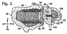
図2は、橈骨56及び尺骨58の近位‐遠位平面を通じて実質的に切り取られたシステム50の断面図を示す。例示的な解剖学的な軸、すなわち内側‐外側軸(M−L)及び背面‐前面軸(Do−V)は、示される。
FIG. 2 shows a cross-sectional view of
橈骨人工関節52及び尺骨人工関節54は、下橈尺関節における人工関節置換表面として機能するために、互いに面しており、且つ互いに可動に接触する各外側表面90、92を備えることができる。現在の例において、下橈尺関節の橈骨側及び尺骨側の両方は、人工関節全置換術において、人工関節関節表面と置換される。しかしながら、他の例において、橈骨側のみ又は尺骨側のみは、半関節形成術において、橈骨人工関節又は尺骨人工関節とそれぞれ置換される場合がある。言い換えると、設置後の橈骨人工関節(又は、尺骨人工関節)は、下橈尺関節において、置換関節接合表面又は生来の関節接合表面と関節をなす場合がある。
The
A.橈骨人工関節
図2〜4は、橈骨人工関節52のさらなる態様を示す。橈骨人工関節は、一体式とされてもよい(又は一体式とされてなくてもよい)プレート94として組み立てられることができる。橈骨人工関節は、外側表面90と対向する内側表面96を有することができる。内側表面は、数ある中で、平坦とされてもよく(すなわち、少なくとも略平面とされてもよい)、又は、(例えば、凸状に)湾曲されてもよい。内側表面は、数ある中で、突出部(例えば、一体式の突出部)がなくてもよく、又は該内側表面から突出している少なくとも1つの一体式のステム及び/又はリッジを有してもよい。
A. Rib Prosthesis FIGS. 2-4 show further embodiments of the
外側表面90は、側部表面98によって分離されることができ、人工関節の外周を形成することができる。該側部表面は、直線状の輪郭(例えば、図4を参照する)を形成するために少なくとも略平坦とされてもよく、又は湾曲した輪郭を形成するために、曲面とされてもよい。いずれにしても、ここで示されるように側部表面98が出会う角部は、丸みを帯びてもよく、鋭くてもよく、又は(例えば、円状の構成において)存在しなくてもよい。該側部表面は、内側表面96に対して少なくとも実質的に直交するように方向付けされてもよい。少なくとも1対の対向した側部表面98は、互いに対して平行(又は、傾斜)とされるそれぞれ長軸を規定することができる。それ故に、いくつかの実施形態において、橈骨人工関節は、数ある中で、少なくとも略矩形状(すなわち、長方形又は正方形)又は台形状である四角形形状を形成するように、4つの側部表面を有する場合がある。他の実施形態において、橈骨人工関節は、円状、楕円形状、4つの側部より多い多角形状又は少ない多角形状、又は同様のものとされてもよい。
The
橈骨人工関節は、図1、図2、及び図4に示されるように、骨内にはめ込まれるように(骨内に挿入されるように)組み立てられてもよい。言い換えると、橈骨人工関節は、S字状洞溝102内に形成されたキャビティ100に部分的又は少なくとも実質的に完全に受容されることができ、それによって、人工関節が、(図2及び図4に見られるように)側部表面98が壁部104に面する状態で、キャビティの壁部104によって周囲を囲まれる。設置時に、外側表面90は、橈骨の周囲表面領域106と少なくとも実質的に同一平面とされてもよく(又は、同一平面とされなくてもよい)、該位置において、(図4に見られるように)人工関節の外側表面90が骨表面領域106に出会う。
The radial prosthesis may be assembled to fit within the bone (inserted into the bone) as shown in FIGS. 1, 2 and 4. In other words, the radial prosthesis can be partially or at least substantially completely received in the
橈骨人工関節は、任意の適切な寸法を有することができる。例えば、橈骨人工関節は、その幅より大きい長さ又はその幅と等しい長さを有してもよい。橈骨人工関節の厚さは、長さ及び/又は幅より実質的に小さくてもよく、例えば、長さ及び/又は幅の約半分しかなくてもよい。該厚さは、内側表面及び外側表面が相補的な形状を有する場合に、以下に記載されるように、人工関節に亘って変化してもよく、又は一定でもよい。例示的な実施形態において、単に図示のために意図されるが、橈骨人工関節は、典型的な大人の患者のために、約3/4インチ(19mm)の幅、5/8インチ(16mm)の長さ、1/4インチ(6.3mm)の深さとされてもよい。 The radius prosthesis can have any suitable dimensions. For example, a radius prosthesis may have a length greater than or equal to its width. The thickness of the radius prosthesis may be substantially less than the length and / or width, for example, may be only about half the length and / or width. The thickness may vary across the prosthesis, as described below, or may be constant when the inner and outer surfaces have complementary shapes. In the exemplary embodiment, although intended only for illustration, the radial prosthesis is approximately 3/4 inch (19 mm) wide and 5/8 inch (16 mm) for a typical adult patient. And a depth of 1/4 inch (6.3 mm).
橈骨人工関節(及び/又は、尺骨人工関節)は、(図3に見られるように)任意の適切な種類の孔108、孔108の任意の適切な数、及び孔108の任意の適切な配置を有してもよい。例えば、橈骨人工関節52は、各角部に隣接して孔を画定してもよい。いずれにしても、各孔は、骨ねじなどの固定具を受容するために構成されてもよい。該孔は、貫通孔、例えば、人工関節の内側表面と外側表面との間に延在する貫通孔とされてもよく、又は人工関節を貫いて完全に延在しなくてもよい(以下を参照)。該孔は、螺合係合によって固定具に固定される雌ねじ付きの孔などの、固定孔とされてもよく、又は固定具との螺合係合なしで、固定具を受容する圧縮孔/トグル孔とされてもよい。それ故に、該孔は、固定具の配置のための軸を既定してもよく、又は、角度の範囲間で固定具の配置を可能してもよい。いくつかの実施形態において、橈骨人工関節は、1つ又は複数の固定孔及び1つ又は複数の(固定されない)圧縮孔/トグル孔の組み合わせを含んでもよい。
The radius prosthesis (and / or ulna prosthesis) may be any suitable type of holes 108 (as seen in FIG. 3), any suitable number of
固定具60は、孔108内に受容されてもよく、任意の適切な距離を通じて、及び任意の適切な方向において、骨内に前進されてもよい(図2及び図4に見られる。)。各固定具60は、例えば、隆起ねじ部(prominent thread)を有する、海綿骨ねじ(cancellous bone screw)とされてもよい。該固定具は、例えば、橈骨に亘って(内側から外側へ)、少なくとも約1/3の距離、少なくとも約半分の距離、少なくとも約3/4の距離で延在してもよい。少なくとも一対の固定具60は、互いに対して平行に延在されてもよく、又は人工関節から離れるように延在すると、発散してもよく、又は収束してもよい。一対の固定具の発散性及び収束性は、背面‐前面方向、内側‐外側方向、近位‐遠位方向、又はそれらの任意の組みわせとされてもよい。それらの場合において、複数の固定具は、固定具の外側に広げられた配置(splayed-out arrangement)を提供するために、橈骨人工関節から延在されるにつれて互いから発散してもよく、それによって、該固定具が、骨に対して人工関節をより効率的に固定することができる。いくつかの実施形態において、少なくとも1つの固定具は、人工関節へ接近し、(すなわち、外側から内側方向における固定具の配置によって)逆方向(retrograde direction)において人工関節に対して固定してもよく、又は、(例えば、セクションVを参照して)背面方向又は前面方向から人工関節の側部表面を介して受容されてもよい。
The
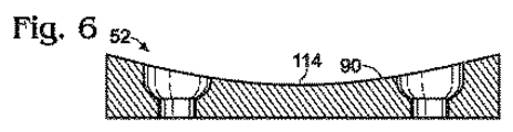
図3〜10は、橈骨人工関節52の外側表面90のための例示的な形状を示す。外側表面90は、外側表面の三次元輪郭の理解を容易にするために、教示の目的で、図3で点描されるように描かれている。該外側表面は一般的に、修復された関節で体液の移動を促すために、非常に滑らかである、より適切に言えばより滑らかに研磨されている。
3-10 illustrate an exemplary shape for the
外側表面90は、窪んでいてもよい。言い換えれば、該外側表面は、互いに少なくとも実質的に直交している2つの方向のそれぞれにおいて、凹面状の湾曲を有してもよい。
いくつかの実施形態において、外側表面は、複合湾曲で形成されてもよく、該複合湾曲は、該人工関節が設置される場合に、該人工関節の特徴的な長さ軸110及び特徴的な幅軸112に対して、及び/又は解剖学的な軸に対して、画定されることができる。該外側表面は、該人工関節の幅軸112に対して平行な軸に関して、及び/又は、近位‐遠位軸に対して平行な軸に関して、略中央に配置された第1の凹状の湾曲を有してもよく、それによって、橈骨人工関節が橈骨に対して動作可能に取り付けられる場合に、第1の凹状の湾曲は、人工関節における長さ方向に、及び/又は背面‐前面方向に、実質的に延在する。該外側表面90はまた、人工関節の長さ軸110に対して平行又は傾斜する軸に関して、及び/又は(図3におけるDo−Vとして記載されるように)1つ又は複数の背面‐前面軸に対して平行又は傾斜する軸に関して、略中央に配置された第2の凹状の湾曲を有してもよく、それによって、橈骨人工関節が橈骨に対して動作可能に取り付けられる場合に、第2の凹状の湾曲は、人工関節における幅方向に、及び/又は、近位‐遠位方向に(又は近位‐遠位方向に対して傾斜して)、実質的に延在する。
The
In some embodiments, the outer surface may be formed with a compound curve that is characterized by a
外側表面90の複合湾曲は、溝114を形成してもよい。該溝114は、浅く、徐々に丸みを帯びる(shallow, gently rounded trough)場合がある。該溝は、図3及び図4において鎖線によって印付けされており、図5〜図10において示された橈骨人工関節52の断面図において可視される。該溝は、設置時に、長さ軸110に対して平行に、及び/又は解剖学的に規定された背面‐前面方向に対して略平行に、方向付けられてもよい。代替的には、該溝は、図3〜10に示されるように長さ軸110に対して傾斜するように方向付けられてもよい。例えば、溝114は、長さ軸110に対して、及び/又は、該人工関節が(例えば、より遠位の背面位置からより近位の前面位置への傾斜角で)設置される場合に、解剖学的に規定された背面‐前面軸に対して、約5°〜25°の傾斜角、約10°〜20°の傾斜角、又は約15°の傾斜角で延在してもよい。
The compound curvature of the
該溝114は、下橈尺関節の主要な荷重負荷軸を示してもよい。それ故に、尺骨の座部(及び/又は、尺骨人工関節によって提供された人工関節の座部)は、橈骨及び尺骨に対する手末端部が回外運動から回内運動へ移動されるときに、図3及び図4において左側から右側への実質的な回転運動及び並進運動によって、該溝に沿って変位してもよい。それ故に、溝が傾斜するように方向付けられる場合に、尺骨の座部が、手の回外運動と回内運動との間で、溝に沿って回転し、且つ並進するので、橈骨の遠位端部の近位‐遠位位置は、(例えば、約4mm〜5mmだけ)変化してもよい。溝114はそれ故に、関節機能のより良好な復元のために、生来の下橈尺関節の動作を再生する人工関節運動を促してもよい。
The
図11及び図12は、下橈尺関節の橈骨部分を置換する他の例示的な橈骨人工関節130を支承する遠位の橈骨56の内側図及び断面図をそれぞれ示す。橈骨人工関節130は、橈骨人工関節(例えば、橈骨人工関節52)の本願開示において、他の場所に記載される特徴の任意の組み合わせを有してもよい。
11 and 12 show a medial view and a cross-sectional view, respectively, of the
橈骨人工関節130は、表面部材(前方部材)132及びベース(後方部材)134を含む複数の部材とされてもよい。ベースは、骨に固定されてもよく、表面部材を骨に接続するために、骨と表面部材との間でブリッジとして役立ってもよい。表面部材及びベースは、同一の材料又は異なる材料から形成されてもよい。例えば、ベースは、金属(例えばチタニウム)から形成されてもよく、表面部材は、数ある中で、プラスチック(例えば、超高分子量ポリエチレン)又は金属(例えば、コバルトクロム)から形成されてもよい。それ故に、複数の部材からなる人工関節の使用は、材料の選択において多くの自由を提供する。ベース及び表面部材のための他の適切な材料は、以下のセクションIIIで記載される。 The radius artificial joint 130 may be a plurality of members including a surface member (anterior member) 132 and a base (an posterior member) 134. The base may be secured to the bone and may serve as a bridge between the bone and the surface member to connect the surface member to the bone. The surface member and the base may be formed from the same material or different materials. For example, the base may be formed from a metal (eg, titanium), and the surface member may be formed from plastic (eg, ultra high molecular weight polyethylene) or metal (eg, cobalt chrome), among others. Therefore, the use of a prosthesis composed of a plurality of members offers a lot of freedom in the choice of materials. Other suitable materials for the base and surface members are described in Section III below.
表面部材132は、下橈尺関節の橈骨側を形成するために形作られた外側表面136を有してもよい。例えば、表面部材は、(例えば図3に見られるように)橈骨人工関節52のために上記に記載された溝に類似な溝138を画定してもよい。しかしながら、表面部材は、複数の孔によって遮られない連続的な外側表面を有してもよい。それ故に、表面部材は、例えば、半関節形成術後に、下橈尺関節における関節接合のための刺激の少ない表面(less-irritating surface)を提供する場合がある。
The
ベース134は、表面部材と骨との間でブリッジを形成することによって、骨に対する表面部材132の固定接続を可能にしてもよい。ベースは、骨と係合するために、橈骨のS字状洞溝内に形成されたキャビティ140内で受容されてもよい。ベースは、任意の適切な機構によって橈骨に取り付けられてもよい。例えば、ベースは、ベースを骨に取り付けるために、ねじ付き固定具144を受容する1つ又は複数の孔142を画定してもよい。代替的には、又はさらに、ベースは、数ある中で、接着剤(例えば、骨セメント)で、圧入(例えば、橈骨における小形の孔内にベースのステムを押し込むことによって)、又はそれらの組み合わせで、骨に固定されてもよい。橈骨に対する取付後に、ベースは、表面部材と係合されてもよい。例えば、ベースは、ベースの外側表面上に及び/又は外側表面において、及び表面部材の内側表面上に及び/又は内側表面において形成された、少なくとも略補完的な固着構造146によって提供されたスナップ嵌め式接続で表面部材を受容してもよい。他の実施形態において、表面部材は、ベースに取り付けられる場合に、骨の1つ又は複数の側部表面に亘って延在してもよい。スナップ嵌め式接続よりはむしろ、又はスナップ嵌め式接続に追加して、表面部材は、数ある中で、固定具及び/又は接着剤を介して骨に固定されてもよい。
B.尺骨人工関節
図1及び図2は、尺骨人工関節54のさらなる態様を示す。尺骨人工関節は、橈骨人工関節のために上記に記載される特徴のいずれかを有してもよい。例えば、尺骨人工関節は、単一部材として形成されてもよい。代替的には、尺骨人工関節は、橈骨人工関節130(図11及び12)のために実質的に記載されるように、内側ベース及び別個の外側表面部材などの、複数の部材からなる構成とされてもよい。同様に、尺骨人工関節は、貫通孔又は止まり孔(blind hole)とされる1つ又は複数の孔を画定する場合がある。例えば、本願の図示において、尺骨人工関節は、その先端部でラグスクリュー(lag screws)62に固定される一対の雌ねじ付き孔160を画定する。
B. Ulna Prosthesis FIGS. 1 and 2 show a further embodiment of the
尺骨人工関節は、(図1及び図2に見られるように)外側表面92と実質的に対向する内側表面162を含んでもよい。内側表面は、数ある中で、(一の平面において主として)平坦とされてもよく、互いに対して鋭角で、直角で、又は鈍角で配置された少なくとも2つの平坦な表面からなってもよく、(例えば、球形状に)湾曲されてもよく、又はその組み合わせでもよい。
The ulna prosthesis may include an
尺骨人工関節(及び/又は、橈骨人工関節)は、内側表面162及び外側表面92を形成する本体164と、内側表面162から突出しているステム166とを備えてもよい。ステムは、本体に固定されてもよく、内側表面162に対して直交するように、又は傾斜するように、突出してもよい。ステムは、本体と一体化されてもよく、別個の離散的な部材によって形成されてもよい。ステムは、例えば、尺骨における孔内へのステムの挿入を容易にするために、丸められた先端及び/又は先細された先端を有する少なくとも略円柱状とされてもよい。該ステムは、数ある中で、髄管に対して傾斜するように、又は直交するように、骨内に形成された孔内に配置されるように構成されてもよく、及び/又は、尺骨の髄管に沿って配置されてもよい。
The ulna prosthesis (and / or radius prosthesis) may include a
尺骨人工関節54の外側表面92は、S字状洞溝又は橈骨人工関節との関節接合領域において、任意の適切な形状を有してもよい。例えば、関節接合領域は、数ある中で、略円球形状又は略円柱状とされてもよい。いくつかの実施形態において、下橈尺関節における橈骨人工関節又は生来の橈骨と関節をなす外側表面92の一領域は、(例えば、図2に見られるように)橈骨人工関節52の背面‐前面の湾曲より大きい背面‐前面の湾曲(すなわち、小さな曲率半径)を有してもよい。本体164は、(図1に見られるように)本体の大部分から近位方向に延在するテール部168を形成してもよい(又は、形成しなくてもよい)。
The outer surface 92 of the
軟骨下骨(subchondral bone)に当接する人工関節の任意の骨接触表面は、骨成長及び/又は骨に対する癒着を促進するために変更されてもよい。例示的な骨接触表面は、尺骨人工関節54の内側表面162及びステム166と、橈骨人工関節52の内側表面96及び必要に応じて側部表面98と、を含む。例示的な変更は、プラズマ処理、グリッドブラスト(grit-blasting)、又は同様のものを含んでもよい。同様に、軟骨下骨に当接する人工関節の骨接触表面は、接着剤(例えば、骨セメント)で骨に取り付けられてもよい。該接着剤は、代替的に使用されもよく、又は1つまたは複数の固定具に追加して使用されてもよい。
Any bone contacting surface of the prosthesis that abuts the subchondral bone may be altered to promote bone growth and / or adhesion to the bone. Exemplary bone contacting surfaces include the
[II.下橈尺関節の表面置換方法]
本願開示は、下橈尺関節の少なくとも1つの表面領域を置換する方法を提供する。該方法は、このセクション及び本願開示における他の場所で示されたステップの任意の適切な組み合わせ及び順序を採用する場合がある。図13〜22は、下橈尺関節の少なくとも1つの関節接合表面領域を人工関節表面領域と置換する方法で実行されることができる例示的なステップに対応している、且つ/又は例示的なステップを図示している例示的な構成を示す。システム50(図1)の橈骨人工関節及び尺骨人工関節の設置及び取付は、それらの図面に示される。
[II. Surface replacement method for lower knee joint]
The present disclosure provides a method for replacing at least one surface region of a lower radioulnar joint. The method may employ any suitable combination and order of steps shown in this section and elsewhere in this disclosure. FIGS. 13-22 correspond to and / or exemplary steps that can be performed in a method for replacing at least one articulating surface region of a lower radioulnar joint with a prosthetic surface region. 2 shows an exemplary configuration illustrating steps. The installation and attachment of the radial and ulnar prostheses of the system 50 (FIG. 1) is shown in those drawings.
図13は、骨の適切な切除と、システム50のコンポーネントの位置及び取付とを容易にするために、直線状の基準線又は案内軸180の確立中の、患者の右側前腕の橈骨56及び尺骨58の遠位領域の背面図を示す。遠位尺骨58及び下橈尺関節51は、数ある中で、背面/内側側部又は前面/内側側部から軟組織を通じてアクセスされてもよい。
FIG. 13 illustrates the patient's
基準線180を確立するために、堅いワイヤー(例えば、約0.062インチ(1.6mm)のKワイヤー、例えば約1mm〜約2mmのKワイヤー)又はピンなどの細長いガイド部材182は、遠位尺骨頭の内側側部で始まる挿入ポイントから、実質的に内側から外側への方向において、尺骨及び橈骨内に挿入されてもよい。ガイド部材の先端部184は、下橈尺関節51を通じて、且つ橈骨56及び尺骨58の他の表面に対して基準線180を画定するように、下橈尺関節51を通じて配置されてもよく、且つ特に、その橈骨関節接合表面及び尺骨関節接合表面を通じて、配置されてもよい。該ガイド部材は、橈骨56及び尺骨58の長手方向軸に対して直交するように配置されてもよく、又は図13に示されるように、近位から遠位への傾斜状態で傾斜するように配置されてもよい。例示的な配置の垂直ではない角度は、数ある中で、約5°〜約35°、約10°〜約30°、約15°〜約25°、又は20°を含む。
To establish the
ガイド部材182の配置は、フリーハンドで実行されてもよく、又は照準工具190によって容易にされてもよい。照準工具190は、クランプを形成するように、調整可能で固定可能な長さの本体192が対向するアーム194、196に接続された状態で、略C字状とされてもよい。アームの位置は、固定ノブ198を使用して固定されてもよい。それによって、照準工具が、前腕に対して圧縮され、前腕に対して締め付けられることができる。第1のアーム194は、ガイド部材を受容し、且つガイド部材を方向付けるボア200を画定することができる。骨は、第2のアーム196に設けられたフィンガー202などの、既定済み部位を交差する直線状の軸を画定することができる。使用時に、第1のアーム194は、遠位尺骨頭の内側表面部位に対して配置されてもよく、フィンガー202は、遠位橈骨の外側部位に亘って肌(又は骨)に対して配置されてもよく、それによって、照準工具190は、適所で締め付けられることができる。X線透視装置は、同様に、又は代替的に、位置付けを監視するために、且つ該関節及び骨を通じて所望な配置を可能にするために、ガイド部材の配置中に利用されてもよい。
The placement of
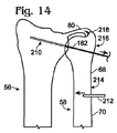
図14は、参照符号210で示されるように、ガイド部材182が部分的に引き抜かれた状態で、骨切除術が鋸などの切断工具212によって尺骨58で実行されるときの、図13の橈骨56及び尺骨58の背面図を示す。言い換えれば、尺骨が無処置であると仮定して、尺骨58のシャフト領域214は、遠位尺骨断片68及び近位尺骨断片70を形成するために、骨を通じて完全に、(尺骨の長手方向軸に対して直交するように又は傾斜するように)横断方向に切断される場合がある。遠位尺骨は、約3インチ(76mm)程度又はわずか約3インチなどの、その遠位先端部218から適切な距離で、その遠位頭216に対して近位で切断される場合があり、橈骨56及び尺骨58を接続する靭帯80、腱、血管、及び同様のものを無傷な状態にすることができる。
FIG. 14 illustrates the ribs of FIG. 13 when osteotomy is performed on the
図15は、遠位尺骨断片が近位尺骨断片に対して離隔した構成で配置された状態、例えば、参照符号230で示されるように、(同様に、回動した構成又はヒンジアウトした構成(hinged-out configuration)と称される)反転した構成で配置された状態での、尺骨の骨切除術(図14)後の橈骨56及び尺骨58の背面図を示す。尺骨断片の分離は、近位尺骨断片70から離れるように遠位尺骨断片68を移動することによって達成されてもよい。例えば、遠位尺骨断片68は、遠位尺骨断片を略内側に、且つ橈骨56及び近位尺骨断片70から離れるように回動することによって、反転した構成になるように移動されてもよい。反転した構成は、数ある中で、少なくとも約20°、少なくとも約40°、少なくとも60°、及び少なくとも90°などの任意の適切な角度によって遠位尺骨断片68の再度の方向付けを表してもよい。同様に、他のガイド部材232は、(図13にも見られるように、)ガイド部材182によって形成された橈骨56におけるチャンネル234内に配置されてもよい。
FIG. 15 shows the distal ulna fragment placed in a spaced configuration relative to the proximal ulna fragment, eg, as shown by reference numeral 230 (similarly rotated or hinged configuration ( FIG. 14 shows a rear view of the
一般的に、反転した構成において、遠位尺骨断片の血液供給は、三角線維軟骨複合体の十分に血管化された取付(richly vascularized attachment)と無傷の骨膜スリーブに対する包囲カプセル取付(surrounding capsular attachment)とによって維持されてもよい。言い換えれば、反転した構成は、その血液供給の遠位尺骨断片を剥離しなくてもよく、それによって、乏血壊死を避けることができる。 In general, in the inverted configuration, the blood supply of the distal ulnar fragment provides a fully vascularized attachment of a triangular fibrocartilage complex and a surrounding capsule attachment to an intact periosteal sleeve. And may be maintained by In other words, the inverted configuration does not require detachment of the blood supply's distal ulna fragment, thereby avoiding ischemic necrosis.
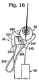
図16は、骨が図15に示されるように位置付けされた状態、及び箱たがね(box chisel)と称されるエッチング工具240がS字状洞溝102上で動作可能に配置される状態の、橈骨56及び尺骨58の内側図を示す。エッチング工具240は、(図13に見られるように)基準線180に対してエッチング工具240の適切な近位‐遠位の位置付け及び背面‐前面の位置付けを提供するために、(図15に見られるように)ガイド部材232を受容する開口部242を画定してもよい。エッチング工具は、置換されるべきであるS字状洞溝の表面領域のための境界又は縁の輪郭を描く(且つ切断する)ために使用されてもよい。エッチング工具240は、橈骨人工関節52の利用可能なサイズを受容するために準備されるべきS字状洞溝の領域を寸法決めし、且つ形成する際に、ガイドとして使用されることができる。エッチング工具240は、開口部242を規定し、且つ把持可能なハンドル246に接続されるヘッド244を含んでもよい。ヘッド244は、所定の形状で橈骨人工関節に対応することができるブレード248を備えてもよい。エッチング工具240がS字状洞溝102に適切に位置付けられる状態で、外科医は、ブレード248をS字状洞溝102内に至らせるように、例えば木槌で、ヘッド244を打ちつけてもよく、それ故に、掘削されるべきS字状洞溝の表面領域250の境界を規定することができる。エッチング工具230のさらなる態様は、以下に記載されるであろう。
FIG. 16 shows a state in which the bone is positioned as shown in FIG. 15 and an
図17は、(図16にも見られる)表面領域250の周りの境界252に印をつけるために、又は該境界252を切断するために、エッチング工具240の使用後の橈骨56の背面図を示す。バー256に装着された動力ドリルなどの掘削工具254は、S字状洞溝102内のキャビティ258を形成するために使用されることができる。キャビティの寸法及び形状は、境界252によって規定されることができる。キャビティ258の深さは、キャビティ内に移植されるであろう橈骨人工関節の厚さに対応してもよい。
FIG. 17 shows a rear view of
図18は、キャビティ258内の橈骨人工関節52の配置及び固定具60による橈骨に対する取付後の橈骨56の内側図を示す。他の例において、橈骨人工関節52は、(図1に見られるように)尺骨人工関節54後に設置されてもよく、又は、半関節形成術中に尺骨人工関節なしで利用されてもよい。言い換えれば、橈骨人工関節が設置された状態で、尺骨56が別の方法で衝撃を与えられない修復において、尺骨は、固定装置及び固定具(例えば、骨プレート及び骨ねじ)を使用して再度組み立てられてもよく、該部位は閉鎖される。
FIG. 18 shows the medial view of the
図19〜22は、(図19及び図21に見られるように)尺骨が穴をあけられる(又は、穴あけのために準備される)ときの、(図20に見られるように)尺骨が切除されるときの、及び(図22に見られるように)尺骨が固定されるときの、橈骨56及び尺骨58の背面図を示す。それらの手順は、任意の適切な順番で、尺骨で実施されることができる。
同様に、手順のいずれかは、橈骨が堀削され、且つ橈骨人工関節が移植される前又は後で、尺骨で実施されることができる。さらに、手順のいずれかは、下橈尺関節の半関節形成術において実施されてもよい。
19-22 show that when the ulna is punctured (or prepared for drilling) (as seen in FIGS. 19 and 21), the ulna is excised (as seen in FIG. 20). FIG. 23 shows a rear view of the
Similarly, any of the procedures can be performed on the ulna before or after the radius is excavated and the radial prosthesis is implanted. Further, any of the procedures may be performed in a semi-arthroplasty of the lower radioulnar joint.
図19は、尺骨内に穴あけのための経路を画定するために、その内側側部から尺骨58内へのガイドピン270及び272の挿入を図示する。テンプレート274は、ガイドピン270及び272を配置するために利用されることができる。該テンプレートは、ガイド部材182を受容するためのボア276と、ガイドピン270及び272を位置付けし、且つガイドピン270及び272の挿入を案内するための、1つ又は複数のボア278、280とを画定してもよい。テンプレート274のボア278、280は、(図1及び図2に見られるように)尺骨人工関節54の特徴と関連して配置されてもよい。例えば、ボア278、280は、(図1に見られるように)尺骨人工関節54のねじ付き孔160の分離に一致するように離隔されてもよい。骨内へのガイドピン270及び272の配置後に、テンプレート274は取り除かれてもよく、穴282、284は、カニューレ処置されたドリルビット(cannulated drill bit)でガイドピンに亘って穴をあけることによって形成されてもよい。
FIG. 19 illustrates the insertion of guide pins 270 and 272 into the
図20は、尺骨58の遠位頭216の外側部分の切除を図示する。切断ガイド290は、遠位尺骨の背面表面(又は前面表面)に隣接してガイドスロット292(又は、ガイド面)を位置付けるために、ガイド部材182上に受容されてもよい。該ガイドスロットは、尺骨の長手方向軸に対して、数ある中で約10°〜約30°又は約20°等の任意の適切な角度で配置されてもよい。該ガイドスロット(又は、ガイド面)は、遠位頭216に対して近位とされてもよい尺骨のより近位の外側表面領域294から遠位頭216の遠位端部表面領域286まで延在している切断面を規定してもよく、該遠位端部表面領域286は、尺骨小窩(ulnar fovea)298に隣接して外側に配置されてもよく、且つ尺骨の中心長手方向軸を越えて内側に配置されてもよい。動力鋸(例えば、往復運動動力鋸)などの切断工具300は、ガイドスロット292によって案内された尺骨の切除部分302を取り除いてもよい。他の実施形態において、尺骨頭の外側部分は、(例えば、図14に見られるように)尺骨が近位セグメント及び遠位セグメントに切断される前に、取り除かれてもよい(切断されてもよい)。
FIG. 20 illustrates resection of the outer portion of the
図21は、(例えば、図1に見られるように)尺骨人工関節54のステム166を受容するために、尺骨58において穴310をあけることを図示する。穴310は、基準線180と同心とされてもよく、且つカニューレ処置されたドリルビット312でガイド部材182亘って穴をあけることによって形成されてもよい。穴あけは、尺骨が近位セグメント及び遠位セグメントに切断された後で、尺骨が反転した構成になる状態で、尺骨58の外側側部から実行されてもよい。
FIG. 21 illustrates drilling a
図22は、固定装置64、すなわち複数の骨ねじ320で固定された骨プレート66を使用する尺骨58の再組み立てを図示する。尺骨58を再度組み立てることは、遠位尺骨断片68を、反転した構成から近位尺骨断片70と軸方向に位置合わせされた状態へ回動させることを含んでもよい。位置合わせされた断片は、数ある中で、骨プレート、1つ又は複数の骨ねじ、1つ又は複数のピン、外側骨折固定器、髄内ネイル(intramedullary nail)、又はその任意の組み合わせ等の任意の適切な固定装置で固定されてもよい。
FIG. 22 illustrates reassembly of the
図23は、(図16にも見られるように)該工具の切断側から見たエッチング工具240を示す。エッチング工具240は、切れ刃332を形成するために、ヘッド244のプレート330から直交するように突出しているブレード248を含んでもよい。ブレード248は、閉鎖されたループにおいて、ヘッドの外周の周りで延在してもよい。ブレードは、移植されるべき橈骨人工関節の厚さに対応する深さを有してもよい。骨内へのブレード248の進行は、骨とのプレート330の接触によって、停止されてもよい。同様に、ブレード248は、その寸法及び形状で移植されるべき橈骨人工関節に対応する領域の周囲を囲んでもよい(circumscribe)。しかしながら、該領域は、移植時に、骨との橈骨人工関節の締りばめを得るために、橈骨人工関節の寸法に対して僅かに小さくてもよい。
FIG. 23 shows the
図24は、下橈尺関節において、対応する橈骨人工関節の設置前に、暫定的に設置されてもよい例示的な試用インプラント340を示す。試用インプラント340は通常、その寸法及び形状において、図3に示された橈骨人工関節52などの、橈骨人工関節に対応してもよい。該試用インプラントの使用は、橈骨人工関節の適切な寸法及び/又は形状が、設置のために別の寸法及び形状の一組の橈骨人工関節から選択されることを可能にしてもよい。代替的には、又は追加して、試行インプラントの使用は、橈骨人工関節が移植される前に、S字状洞溝内で形成されたキャビティの寸法及び形状の評価を可能にしてもよい。試行インプラント340は、雌ねじを有する孔342を画定してもよい。
FIG. 24 shows an
図25は、試用アプリケータ350に取り付けられ、且つ橈骨56のS字状洞溝内で形成されたキャビティ352内で、暫定的に設置された試用インプラント340を示す。該試用インプラント340は、孔342に固定された蝶ねじ354によって、試用アプリケータ350に取り付けられてもよい。表面356は、試用インプラント340の挿入に役立つように、工具で打ちつけるために試用アプリケータ350に提供されてもよい。該アプリケータは、試用インプラントの装着を検査するために、試用インプラントから切り離されてもよく、試用インプラントの除去のためのレバーアームを提供するために再接続されてもよい。
FIG. 25 shows the
図26は、例示的な切断ガイド360が尺骨に対して位置付けられ、且つ鋸のための案内経路を規定する状態の、橈骨56及び尺骨58の遠位図を示す。切断ガイド360は、図20の切断ガイド290のために記載されるように通常使用されてもよい。切断ガイドは、ガイド部材182のためのレシーバ362と、背面‐前面調整機構364と、内側‐外側調整機構366と、ガイド面368と、を含んでよい。
FIG. 26 shows a distal view of
レシーバ362は、通路を画定するT字状部材370内に含まれてもよく、それによって、T字状部材370がガイド部材182上でスライドすることを可能にする。直角エルボー374の脚部372は、T字状部材370の自由脚部376上でスライドしてもよく、ガイド面368を保持するL字状部材378は、直角エルボー374の残留脚部380内へスライドされてもよい。ガイド面368を保持するL字状部材378の遠方端部は、尺骨の遠位頭216に対して至らせてもよい。直角エルボー374の脚部372及び残留脚部380の両方上の蝶ねじ382は、該直角エルボー374に対してT字状部材370及びL字状部材378の相対位置を固定するために締め付けられてもよい。
図27は、切断ガイド360の断面図を示す。ガイド面368及び/又はガイドスロット384は、遠位尺骨頭216の部分的な切除を案内するために、尺骨58の長手方向軸に対して例えば約20°の適切な解剖学的角度で鋸身を案内するために使用されてもよい。
FIG. 27 shows a cross-sectional view of the cutting
図28A及び図29Aは、下橈尺関節の少なくとも1つの関節接合表面領域を置換する方法の実施中に、生み出される場合がある他の例示的な構成を示す。 28A and 29A illustrate other exemplary configurations that may be created during the performance of a method for replacing at least one articulating surface region of a lower radioulnar joint.
図28Aは、平坦な底部を有する円柱状キャビティ390を形成するために、橈骨56のS字状領域からの骨の除去を示す(橈骨は、明白にするために、部分的に断面として、この図に図示される。)。該キャビティは、ガイド部材182上で受容され、且つ回転可能に駆動された、カニューレ処置されたビット392によって形成されてもよい。それ故に、キャビティ390は、ガイド部材182(及び、それが提供する直線状の基準線)に関して中心に配置されてもよい。ビット392は、数ある中で、例えばドリル又はエンドミルによって提供されてもよい。該キャビティ390の深さは、ビット392上に形成されたストップ394によって制御されてもよい。代替的には、又はさらに、キャビティの深さは、キャビティが形成されると、例えば、ビット392の側部表面上に形成された1つ又は複数の深さマーク396を観察することによって、且つ骨の隣接した表面領域に対してマークの位置を比較することによって、目で制御されることができる。
FIG. 28A shows the removal of bone from the sigmoidal region of the
図28Bは、キャビティ390内に移植される場合があるディスク状の橈骨人工関節398を示す。橈骨人工関節398は、橈骨人工関節52のために上記に記載されるように、溝402を形成している窪んだ外側表面400を含んでもよい。
FIG. 28B shows a disc-shaped
図29Aは、円柱状キャビティ390をより多くの多面体キャビティ412に変更するために、すなわち、該キャビティを矩形状にするために、箱たがね410の使用を示す。箱たがね410は、(図13に見られるように)ガイド部材182に関して箱たがねのヘッド416を中心に配置するための開口部414などの、(図16に見られる)エッチング工具240の上記に記載された特徴のいずれかを有してもよい。ヘッド416は、少なくとも略矩形状のブレードを提供してもよく、該略矩形状のブレードは、隣接したキャビティ390から角部骨材料418を取り除くために使用されてもよい。言い換えれば、箱たがね410は、キャビティの深さを変更することなく、その平坦な底部の領域を拡大することによって、キャビティ390のフットプリントを増加させてもよい。
FIG. 29A illustrates the use of
図29Bは、キャビティ412内に移植されることができる略矩形状の橈骨人工関節430を示す。橈骨人工関節430は、橈骨人工関節52のために上記に記載されるように、溝434を形成している窪んだ外側表面432を含んでもよい。
FIG. 29B shows a generally
[III.インプラントの組成]
本願明細書で開示されたインプラント(人工関節、固定装置、及び/又は固定具)は、任意の適切な生体適合性材料から形成されてもよい。例示的な生物適合性材料は、(1)金属(例えば、チタニウム又はチタニウム合金、コバルト及びクロムを有する合金(コバルト‐クロム)、ステンレス鋼など);(2)プラスチック/ポリマー(例えば、超高分子量ポリエチレン(UHMWPE)、ポリメチル・メタクリレート(PMMA)、ポリテトラフルオロエチレン(PTFE)、ポリエーテルエーテルケトン(PEEK)、ナイロン、ポリプロピレン、及び/又はPMMA/ポリメタクリル酸ヒドロキシエチル(PHEMA));(3)セラミックス(例えば、数ある中で、アルミナ、ベリリア、及び/又はジルコニア);(4)複合物(例えば、カーボンファイバー及び/又はセラミックスを含んでいる(PEEK等の)ポリマーマトリックス);(5)生体再吸収性(生体吸収性)材料又はポリマー(例えば、αヒドロキシカルボン酸(例えば、(PLLA、PDLLA、及び/又はPDLAなどの)ポリ乳酸、ポリグリコール酸、ラクチド/グリコライド共重合体など)、ポリジオキサノン、ポリカプロラクトン、ポリトリメチレンカーボネート、ポリ酸化エチレン、ポリβ-ヒドロキシ酪酸、ポリ-β-ヒドロキシプロピオン酸、ポリ‐δ‐バレロラクトン、他の生体再吸収性ポリエステルなど、のポリマー);及び/又は同様のものなどを含む。
[III. Implant composition]
The implants (prosthetic joints, fixation devices, and / or fixtures) disclosed herein may be formed from any suitable biocompatible material. Exemplary biocompatible materials include: (1) metals (eg, titanium or titanium alloys, alloys with cobalt and chromium (cobalt-chromium), stainless steel, etc.); (2) plastics / polymers (eg, ultra high molecular weight Polyethylene (UHMWPE), polymethyl methacrylate (PMMA), polytetrafluoroethylene (PTFE), polyetheretherketone (PEEK), nylon, polypropylene, and / or PMMA / polyhydroxyethyl methacrylate (PHEMA)); (3) Ceramics (eg, alumina, beryllia, and / or zirconia, among others); (4) composites (eg, polymer matrices (eg, PEEK) containing carbon fibers and / or ceramics); (5) living organisms Resorbability (biological absorption ) Materials or polymers (eg, alpha hydroxy carboxylic acids (eg, polylactic acid (such as PLLA, PDLLA, and / or PDLA), polyglycolic acid, lactide / glycolide copolymers, etc.), polydioxanone, polycaprolactone, poly Polymers of trimethylene carbonate, polyethylene oxide, poly β-hydroxybutyric acid, poly-β-hydroxypropionic acid, poly-δ-valerolactone, other bioresorbable polyesters); and / or the like Including.
下橈尺関節のための人工関節を構成する材料は、様々な要件に基づいて選択されてもよい。例えば、該材料は、人工関節が骨と関節をなす(半関節形成術)ために、又は関節における他の人工関節と関節をなす(人工関節全置換術)ために意図されるかどうかに基づいて選択されてもよい。同様に、又は代替的には、材料は、人工関節が単一部材又は複数の部材(例えば、2つの部材からなる)とされるかに基づいて、選ばれてもよい。 The materials that make up the prosthesis for the lower radioulnar joint may be selected based on various requirements. For example, the material is based on whether the prosthesis is intended to articulate with bone (semi-arthroplasty) or to articulate with other prosthetic joints in the joint (artificial joint replacement) May be selected. Similarly, or alternatively, the material may be selected based on whether the prosthesis is a single member or multiple members (eg, consisting of two members).
半関節形成術で使用された単一部材の尺骨人工関節又は単一部材の橈骨人工関節を形成するための例示的な材料は、チタニウム、複合物(例えば、PEEK、熱分解炭素、セラミックなど)、コバルト‐クロムをプラズマ/ビード溶射したチタニウム(titanium plasma/bead sprayed cobalt-chrome)、又は同様のものを含む。半関節形成術で使用された2つの部材からなる尺骨人工関節又は2つの部材からなる橈骨人工関節を形成するための例示的な材料は、チタニウムから形成された後方部材と、コバルト‐クロムから形成された前方部材と、を含む。それ故に、金属、複合物、又はポリマー/プラスチックは、半関節形成術によって修復された下橈尺関節で骨と関節をなしてもよい。 Exemplary materials for forming a single member ulna prosthesis or a single member rib prosthesis used in hemiarthroplasty are titanium, composites (eg, PEEK, pyrolytic carbon, ceramic, etc.) , Titanium plasma / bead sprayed cobalt-chrome, or the like. Exemplary materials for forming a two-member ulna prosthesis or a two-member radial prosthesis used in hemiarthroplasty include a posterior member formed of titanium and cobalt-chromium. A forward member. Therefore, the metal, composite, or polymer / plastic may articulate with the bone at the lower radioulnar joint repaired by hemiarthroplasty.
人工関節全置換術のための橈骨人工関節及び尺骨人工関節を形成するためにそれぞれ使用された例示的な材料は、同一であってもよく、又は異なってもよい。例えば、橈骨人工関節は、チタニウムの裏地を付けたUHMWPEなどの2部材構造として形成されてもよく、尺骨人工関節は、コバルト‐クロムをプラズマ/ビード溶射したチタニウムの単一部材構造として形成されてもよく、あるいはその逆でもよい。代替的には、橈骨人工関節は、複合物(例えば、PEEK、熱分解炭素、セラミックなど)の単一部材構造として形成されてもよく、尺骨人工関節は、複合物(例えば、PEEK、熱分解炭素、セラミックなど)又はコバルト‐クロムをプラズマ/ビード溶射したチタニウムの単一部材構造として形成されてもよく、あるいはその逆でもよい。さらに、橈骨人工関節及び尺骨人工関節は、コバルト‐クロムをプラズマ/ビード溶射したチタニウムの単一部材構造として形成されてもよい。さらに、橈骨人工関節は、UHMWPE(例えば、骨に接着された)の単一部材構造として形成されてもよく、尺骨人工関節は、コバルト‐クロムをプラズマ/ビード溶射したチタニウムの単一部材構造として形成されてもよく、あるいはその逆でもよい。それ故に、人工関節全置換術によって修復された下橈尺関節は、金属と金属の関節接合、複合物と金属の関節接合、ポリマー/プラスチックと金属の関節接合、複合物と複合物の関節接合、ポリマー/プラスチックと複合物の関節接合、又はポリマー/プラスチックとポリマー/プラスチックの関節接合を提供することができる。 Exemplary materials used to form the radial and ulna prostheses for total joint replacement, respectively, may be the same or different. For example, the radius prosthesis may be formed as a two-member structure such as titanium-lined UHMWPE, while the ulna prosthesis is formed as a titanium / single member structure with cobalt-chrome plasma / bead spraying. Or vice versa. Alternatively, the radius prosthesis may be formed as a single piece structure of a composite (eg, PEEK, pyrolytic carbon, ceramic, etc.) and the ulna prosthesis may be formed of a composite (eg, PEEK, pyrolytic, pyrolysis). Carbon, ceramic, etc.) or cobalt-chrome plasma / bead sprayed titanium single piece structure, or vice versa. Further, the radius prosthesis and the ulna prosthesis may be formed as a single component structure of titanium with plasma / bead spraying of cobalt-chromium. Further, the radius prosthesis may be formed as a single part structure of UHMWPE (eg, bonded to bone), and the ulna prosthesis is as a single part structure of titanium with plasma-bead sprayed cobalt-chromium. It may be formed or vice versa. Therefore, inferior radioulnar joints repaired by total joint replacement are metal-to-metal joints, composite-to-metal joints, polymer / plastic-to-metal joints, composite-to-composite joints. Polymer / plastic and composite articulations, or polymer / plastic and polymer / plastic articulations.
[IV.キット]
下橈尺関節の表面置換のための本願明細書に開示されたシステムコンポーネントの任意の適切な組み合わせは、キットとして提供されることができる。キットは、少なくとも1つの橈骨人工関節及び/又は少なくとも1つの尺骨人工関節を含むことができる。該人工関節は、人工関節全置換術において互いと関節をなすように構成されてもよく、及び/又は、半関節形成術において、下橈尺関節の残っている生来の橈骨表面又は尺骨表面と関節をなすように構成されてもよい。1つ又は複数の人工関節は、右側下橈尺関節又は左側下橈尺関節における使用のために設計されてもよいが、右側下橈尺関節及び左側下橈尺関節の両方における使用のために設計されなくてもよい。代替的には、又はさらに、1つ又は複数の人工関節は、右側下橈尺関節及び左側下橈尺関節の両方における使用のために設計されてもよい。
[IV. kit]
Any suitable combination of system components disclosed herein for surface replacement of the lower knee joint can be provided as a kit. The kit can include at least one radius prosthesis and / or at least one ulna prosthesis. The artificial joints may be configured to articulate with each other in a total joint replacement and / or in a hemiarthroplasty with the remaining natural or ulna surface of the lower radioulnar joint It may be configured to form a joint. The one or more prosthetic joints may be designed for use in the right lower knee joint or the left lower knee joint, but for use in both the right lower knee joint and the left lower knee joint It does not have to be designed. Alternatively, or in addition, the one or more prosthetic joints may be designed for use in both the right and left lower knee joints.
該キットはまた、切断された尺骨を固定するために少なくとも固定装置を備えることができる。該固定装置は、例えば、人工関節の設置を容易にするために、尺骨で実施された骨切除術に広がり、且つ固定するように構成された骨プレートとされてもよい。 The kit can also comprise at least a fixation device for fixing the cut ulna. The fixation device may be, for example, a bone plate configured to spread and fix to an osteotomy performed on the ulna to facilitate placement of the prosthesis.
該キットは、人工関節及び/固定装置を骨に取り付けるために、骨ねじなどの固定具をさらに包含してもよい。代替的には、又はさらに、該キットは、この目的のために骨セメントを備えてもよい。 The kit may further include a fastener, such as a bone screw, for attaching the prosthesis and / or fixation device to the bone. Alternatively or additionally, the kit may comprise bone cement for this purpose.
該キットは、試用インプラント、試用アプリケータ、(遠位の尺骨頭(又は橈骨頭)の部分的な切除のための鋸又は他の切断工具を案内するための)切断ガイド、ガイド部材(例えば、K−ワイヤ又はピン)、下橈尺関節を通じてガイド部材の配置を案内するための照準工具、ガイドピン及び/又はドリルビットを位置付けるためのテンプレート、固定具のための孔を形成し、且つ/又は人工関節を受容するためのキャビティを生成するためのビット、エッチング工具/箱たがね、(例えば、ガイド部材の配置、孔の形成、固定具の挿入、骨の鋸引きなどを駆動するための)1つ又は複数の回転/往復運動駆動装置、反転した構成における遠位尺骨断片を保持する後退装置(retraction device)、使用説明書などの少なくとも1つ又はいずれかの組み合わせを包含してよい。 The kit includes a trial implant, a trial applicator, a cutting guide (for guiding a saw or other cutting tool for partial resection of the distal ulnar head (or radial head)), a guide member (e.g. K-wire or pin), aiming tool for guiding the placement of the guide member through the lower radioulnar joint, template for positioning the guide pin and / or drill bit, forming a hole for the fixture and / or Bits to create cavities for receiving artificial joints, etching tools / box chisel, (eg to drive guide member placement, hole formation, fixture insertion, bone sawing, etc. ) At least one or more of one or more rotational / reciprocating drives, a retraction device that holds the distal ulna fragment in an inverted configuration, instructions for use, etc. It may include the combined viewing.
該キットのコンポーネントは、ケース内に含まれてもよく、及び/又は個々又はグループで包装されてもよい。個々のキットのコンポーネントは、無菌状態で提供されてもよく、又は提供されなくてもよい。コンポーネントのいくつか(例えば、移植されるコンポーネント)は、使い捨てのために設計されてもよいが、他のコンポーネント(例えば、工具及び他の設置アクセサリ)は、再使用されてもよい。 The kit components may be contained within a case and / or packaged individually or in groups. Individual kit components may or may not be provided in a sterile condition. Some of the components (eg, components to be implanted) may be designed for disposable use, while other components (eg, tools and other installation accessories) may be reused.
いくつかの実施形態において、該キットは、異なる寸法及び/又は形状の一組の橈骨人工関節又は一組の尺骨人工関節を含むことができる。一組の異なる寸法及び/又は形状は、集団内で異なる解剖学的構造を収容してもよく、及び/又は外科医が特定の手術のための最良適合を選択することを可能にしてもよい。最良適合の選択は、数ある中で、目で、測定によって、及び/又は検査によって実施されてもよい。 In some embodiments, the kit can include a set of radius prostheses or a set of ulna prostheses of different sizes and / or shapes. A set of different dimensions and / or shapes may accommodate different anatomical structures within the population and / or allow the surgeon to select the best fit for a particular procedure. The best fit selection may be performed by eye, by measurement, and / or by inspection, among other things.
キットは、橈骨及び尺骨によって形成された下橈尺関節を修復するために提供されてもよい。該キットは、下橈尺関節の少なくとも1つの表面領域を置換するために、橈骨人工関節、尺骨人工関節、又は橈骨人工関節及び尺骨人工関節の両方から選択された少なくとも1つの人工関節を備えてもよい。該キットはまた、互いに対して近位尺骨断片及び遠位尺骨断片を固定するために、骨プレートを備えてもよい。いくつかの実施形態において、(a)少なくとも1つの人工関節は、橈骨人工関節の各特徴的な軸に対して傾斜するように方向付けられた溝を形成している外側表面を含む橈骨人工関節を含む。(b)少なくとも1つの人工関節は、凹状の外側表面及び凸状の外側表面をそれぞれ含んでいる橈骨人工関節及び尺骨人工関節を含む。(c)該キットは、異なる寸法及び/又は形状の少なくとも2つの橈骨人工関節、又は異なる寸法及び/又は形状の少なくとも2つの尺骨人工関節、又は少なくとも2つのその両方、を含む。(d)該キットは、異なる寸法及び/又は形状の一組の人工関節の中から人工関節を選択する際に使用のための、及び/又は、人工関節がその中に移植されるべきであるキャビティの寸法及び形状を評価する際に使用のための、少なくとも1つの試用インプラントを備える。(e)該キットは、試用インプラントを暫定的に設置する際に使用のための、アプリケータをさらに備える。(f)該キットは、尺骨に対して位置付けられるように構成され、且つ鋸の案内経路を規定する切断ガイドをさらに備える。又は、(g)(a)から(f)の任意の組み合わせを備える。 A kit may be provided to repair the lower ulnar joint formed by the radius and ulna. The kit includes at least one prosthesis selected from a radius prosthesis, an ulna prosthesis, or both a radius prosthesis and an ulna prosthesis to replace at least one surface region of the lower radioulnar joint. Also good. The kit may also include a bone plate to secure the proximal ulna fragment and the distal ulna fragment relative to each other. In some embodiments, (a) the at least one prosthesis includes a radial surface that forms a groove that is oriented to tilt with respect to each characteristic axis of the radius prosthesis. including. (B) The at least one prosthesis includes a radial prosthesis and an ulna prosthesis that includes a concave outer surface and a convex outer surface, respectively. (C) The kit includes at least two radial prostheses of different sizes and / or shapes, or at least two ulna prostheses of different sizes and / or shapes, or at least two. (D) The kit is for use in selecting a prosthesis from among a set of prostheses of different sizes and / or shapes and / or the prosthesis should be implanted therein At least one trial implant is provided for use in evaluating the size and shape of the cavity. (E) The kit further comprises an applicator for use in provisionally installing the trial implant. (F) The kit further comprises a cutting guide configured to be positioned relative to the ulna and defining a guide path for the saw. Alternatively, (g) any combination of (a) to (f) is provided.
[V.例]
以下の例は、本願開示の選択された態様及び実施形態を記載し、下橈尺関節のための例示的な橈骨人工関節及び尺骨人工関節と、人工関節を設置する例示的な方法と、を含む。人工関節及び/又は方法の任意の適切な態様又は要素は、互いに組み合わされてもよく、又は本願開示の他の場所に記載された任意の他の態様又は要素と組み合わされてもよい。それらの例は、図示のために含められており、本願開示の技術的範囲全体を制限し、且つ規定するために意図されたものではない。
[V. Example]
The following examples describe selected aspects and embodiments of the present disclosure and include exemplary radial and ulnar prostheses for the lower radioulnar joint and an exemplary method of installing the prosthetic joint. Including. Any suitable aspect or element of the prosthesis and / or method may be combined with each other or with any other aspect or element described elsewhere in this disclosure. These examples are included for purposes of illustration and are not intended to limit and define the overall scope of the present disclosure.
例1.一体式プレートを有する尺骨人工関節
この例は、人工関節のヘッド部分から延在しているプレート部分を備えた例示的な尺骨人工関節を記載し、それは、図30及び31に見られる。
Example 1. This example describes an exemplary ulna prosthesis with a plate portion extending from the head portion of the prosthesis, which can be seen in FIGS. 30 and 31.
図30は、遠位の尺骨頭の座部及び極が他の例示的な尺骨人工関節450によって切除され、且つ置換される状態の遠位の尺骨58の背面図を示す。尺骨人工関節は、プレート部分454に接続されたヘッド部分452を含んでもよい。
FIG. 30 shows a rear view of the
ヘッド部分452は、任意の適切な特徴を有してもよい。該ヘッド部分は、遠位の尺骨頭の切除された領域と少なくとも実質的に一致して形成されてもよく、遠位の尺骨頭の切除された領域のための凸状の置換表面456を含んでもよい。置換表面456は、数ある中で、少なくとも略球形状又は少なくとも略円柱状とされてもよい。ヘッド部分は、(例えば、図1の尺骨人工関節54に見られるように)ステム、固定具、又は同様のものを使用して骨に取り付けられてもよい。ヘッド部分はまた、軟組織固定を提供するために設計されてもよい。特に、ヘッド部分は、少なくとも1つの通路458(例えば、「縫合孔」)を規定してもよい。該少なくとも1つの通路458は縫合糸460を受容するために使用されてもよく、該縫合糸460は、軟組織(例えば、三角線維軟骨複合体(TFC)80)をヘッド部分452に連結することができる。該通路は、縫合糸のための入口部位及び出口部位を形成するために、例えば略U字状とされてもよく、例えば人工関節の隣接した三角線維軟骨複合体80の遠位端部に近接して、ヘッド部分の離隔した表面位置の間に延在してもよい。
The
プレート部分454は、尺骨58の外側表面に沿って軸方向に延在するように設計されてもよい。該プレート部分は、1つ又は複数の孔462を画定してもよい。該1つ又は複数の孔462は、尺骨人工関節450を尺骨に取り付ける、例えば骨ねじなどの固定具464を受容することができる。
The
図31は、遠位の尺骨頭の座部及び極が、同様に尺骨を固定する例示的な尺骨人工関節480によって切除され、且つ置換される状態の遠位尺骨58の背面図を示す。人工関節480は、プレート部分484に接続されたヘッド部分482を含んでもよい。プレート部分は、複数の孔486を画定してもよい。該複数の孔486は、尺骨に人工関節480を取り付ける骨ねじなどの固定具488を受容することができる。プレート部分484は、プレート部分が骨の表面に沿って延在しているので、尺骨の周りで部分的にねじられてもよい。例えば、プレート部分は、外側表面領域490から尺骨の背面(又は前面)表面領域492へ延在してもよい。骨の異なる側部に到達することによって、該プレート部分は、さらに近位に延在するように設計されてもよい一方、橈骨の内側表面と尺骨の外側表面との間で配置された骨間膜494に対する広範囲な損傷を避ける。それ故に、プレート部分484は十分長いので、尺骨を通じて横断方向切断部496に広がることができる。該横断方向切断部496は、人工関節の設置を容易にするために、骨切除術において導入されてもよい(例えば、図14及び図15に見られる)。
FIG. 31 shows a rear view of the
例2.反転人工関節を有する下橈尺関節の関節形成術
この例は、「逆の」橈骨人工関節500及び「逆の」尺骨人工関節502を有する下橈尺関節の橈骨表面及び尺骨表面の置換を記載する。該「逆の」橈骨人工関節500及び「逆の」尺骨人工関節502は、凹状の関節接合表面504及び凸状の関節接合表面506を供給し、すなわち逆の関節における解剖学的構造を供給し、それは図32に見られる。
Example 2. Arthroplasty of the lower radioulnar joint with an inverted prosthesis This example describes the replacement of the radial and ulna surfaces of the lower radioulnar joint with the “reverse”
橈骨人工関節500は、略球状本体508と、該略球状本体508の内側表面512から突出しているステム510と、を有してもよい。該略球状本体508は、「前方」方向(内側から外側への方向)において又は「逆」方向(外側から内側への方向)において、固定具514を受容する複数の孔を規定してもよい。例示的な実施形態において、内側表面512は平坦とされてもよく、該略球状本体508は、一部を切除した球状(frustosphehcal)とされてもよい。
The
尺骨人工関節502は、固定具516を使用して、尺骨58の切断表面に固定されてもよい。例えば、該人工関節は、平坦な内側表面518を有してもよい。該平坦な内側表面518は、遠位尺骨頭の外側側面の部分的な切除によって形成された尺骨58の切断面520に当接する。尺骨人工関節の凹状の関節接合表面506は、窪んでいてもよく、近位‐遠位方向及び背面‐前面方向の両方において、橈骨人工関節の湾曲より小さい湾曲を有してもよい(又は有していなくてもよい)。同様に、凹状の関節接合表面506は、橈骨人工関節52(例えば、図3及び図4に見られる)のために上記に記載されるように、遠位の手が回外運動と回内運動との間で移動されると、尺骨の長手方向の動きを案内し、且つ促進するために、背面‐前面軸に対して傾斜するように方向付けられた溝を形成してもよい。
The
尺骨人工関節は、必要に応じて、インプラントの内側表面518から延在するステム522を含んでよい。該ステム522は、横断方向に方向付けされた軸を画定してもよく、又はここで図示されるように、尺骨58の長手方向軸に対して少なくとも略平行とされてもよい。
The ulna prosthesis may optionally include a
例3.尺骨カップ(Ulnar Cap)を有する尺骨座部及び極の置換
この例は、尺骨カップとして構成された例示的な尺骨人工関節の設置及び使用を記載し、それは、図33及び図34に見られる。
Example 3 Replacement of Ulna Seat and Pole with Ulnar Cap This example describes the installation and use of an exemplary ulnar prosthesis configured as an ulna cup, which can be seen in FIGS.
図33は、骨切除術後に、その表面を再仕上げすることを可能にするために、下橈尺関節の尺骨部分542を露出する反転した構成で配置された遠位尺骨断片68の背面図を示す。凹状の再形成領域546を有する表面再仕上げビット544は、尺骨部分542を変更するために、遠位尺骨頭216の外側側面に対して進行されてもよい。表面再仕上げビット544の回転動作は、(図34に見られるように)尺骨人工関節540を受容するための遠位頭216を準備するために、軟骨性硬骨及び/又は軟骨下骨を取り除いてもよい。
FIG. 33 is a rear view of a
図34は、外側突起548を形成するために、表面再仕上げビット544(図33)を有する再形成された遠位頭216後の遠位尺骨断片68の背面図を示す。1つ又は複数のボア550はまた、外側突起に形成されてもよい。尺骨人工関節514は次いで、外側突起548上に設置されてもよい。尺骨人工関節540は、外側突起548に相補的である凹状の内側表面552を有してもよく、また、内側表面552から突出し、ボア550内に打ち込まれる、又は圧入されるように寸法決めされるステム554を備えてもよい。ステム554は、円錐形状、円柱形状、又は同様のものなどの任意の適切な形状を有してもよい。尺骨人工関節540の外側表面556は、下橈尺関節の生来の橈骨部分又は人工の橈骨部分と関節をなすように形成されてもよい。
FIG. 34 shows a rear view of the
例4.橈骨人工関節の逆方向及び横断方向の取付
この例は、逆方向固定具(retrograde fasteners)及び/又は横断方向固定具で橈骨に固定されることができる例示的な橈骨人工関節560を記載し、それは図35〜図37に見られる。
Example 4 Reverse and transverse attachment of the radial prosthesis This example describes an exemplary
図35及び図36は、橈骨人工関節560が骨のS字状洞溝領域内に移植された状態の橈骨56の背面図及び断面図をそれぞれ示しており、図37は、単独の橈骨人工関節560の等角図を示す。橈骨人工関節560は、下橈尺関節における関節接合のための窪んだ外側表面562などの、本願明細書の他の場所に記載された特徴のいずれかを有してもよい。
35 and 36 show a rear view and a cross-sectional view, respectively, of the
橈骨人工関節560は、固定具の任意の適切な組み合わせで、橈骨56に取り付けられてもよい。例えば、橈骨人工関節560は、内側表面566内に形成された孔564を画定してもよい。該人工関節は、複数の孔が形成された個所で、厚くなってもよい(又は、厚くなくてもよい)。それぞれの孔は、例えば橈骨56の外側側部から、内側表面に延在する1つ又は複数の固定具568との螺合係合を提供するように、固定されてもよい。橈骨人工関節560はまた、横断方向孔570を画定してもよい。横断方向孔570は、側部表面572から人工関節内へ延在してもよく、例えば止まり孔とされてもよく、又は例えば人工関節の対向した側部表面574へ延在してもよい(図37)。横断方向孔570は、雌ねじを有する固定孔とされてもよく、又はされなくてもよい。横断方向固定具576は、橈骨56の背面側又は前面側から横断方向孔570内に配置されてもよい(図36及び図37)。横断方向固定具576は、人工関節の対向した側で、骨との螺合係合のために人工関節560を通じて延在してもよい。代替的には、又はさらに、横断方向固定具576は、橈骨人工関節560を通じて完全に延在した状態で、又は完全に延在しない状態で、横断方向孔570に固定されてもよい。
The
例5.骨上に配置された橈骨人工関節
この例は、遠位橈骨に固定され、橈骨の生来の表面輪郭に従う例示的な橈骨人工関節590を記載し、それは、図38に見られる。
Example 5. Radial prosthesis placed on the bone This example describes an exemplary
図38は、橈骨人工関節590を支承する橈骨56の遠位図を示す。該人工関節は、下橈尺関節のための人工関節の橈骨関節接合表面591を供給するために、下橈尺関節の橈骨部分に取り付ける、プレートとして構成されてもよい。該人工関節は、該人工関節の各端部領域596、598を使用して、橈骨の背面表面領域592及び前面表面領域594を覆うために、S字状洞溝領域を覆い、且つS字状洞溝領域を越えて延在してもよい。同様に、該人工関節は、1つ又は複数の固定具602を受容するために、端部領域596、598における1つ又は複数の孔600を画定してもよい。各孔は、固定されてもよく、又は固定されなくてもよい。それ故に、人工関節590は、橈骨の背面側及び/又は前面側から、孔600を通じて固定具を配置することによって、少なくとも部分的に固定されてもよい。いくつかの例において、少なくとも一対の孔は、該一対の一の部材を通じて固定具の先端領域の配置し、且つ該一対の他の部材との螺合係合状態になることを可能にするために、共軸とされてもよい。
FIG. 38 shows a distal view of the
人工関節590は、軟骨下骨の実質的な除去なしで、橈骨上に配置されてもよく、且つ橈骨に固定されてもよい。言い換えれば、該人工関節は、該人工関節がその中に受容されるキャビティの形成なしで設置されてもよい。軟骨は、骨上への橈骨人工関節590の配置前に、橈骨の適切な表面領域から取り除かれてもよい(又は、取り除かれてなくてもよい)。
The
例6.ハイブリッド型の骨プレート及び橈骨人工関節
この例は、遠位橈骨のための骨プレートを橈骨人工関節と組み合わせる例示的なハイブリッド型インプラント610を記載し、それは図39に見られる。
Example 6 Hybrid Bone Plate and Radial Prosthesis This example describes an
図39は、骨プレート部分612及び橈骨人工関節部分614を結合する例示的なインプラント610を支承する骨折した遠位橈骨56の背面図を示す。該骨プレート部分及び該橈骨人工関節部分は、同一部材(例えば、一体式の部材)によって形成されてもよく、又は互いに取付可能であるそれぞれ異なる部材によって形成されてもよい。骨プレート部分612は、遠位橈骨を固定するために、1つ又は複数の骨折616(及び/又は、離断される(osteotomized))を有する遠位橈骨の背面側又は前面側に受容されるように形成されてもよい。橈骨人工関節部分614は、下橈尺関節の凹状の橈骨関節接合表面618を備えてもよい。橈骨人工関節部分は、橈骨上に配置されてもよく、又は橈骨のS字状洞溝領域から軟骨下骨を取り除くことによって形成されたキャビティ内に配置されてもよい。
FIG. 39 shows a rear view of a fractured
例7.橈骨人工関節の逆方向の取付
この例は、遠位橈骨56の外側側部636からプレート634を通じて延在する固定具632によって逆方向において固定された例示的な橈骨人工関節630を記載し、それは図40に見られる。
Example 7. Reverse Attachment of the Radial Prosthesis This example describes an exemplary
プレート634は、固定具のヘッドの係合によって固定具632を安定化されてもよい。さらなる固定具638は、橈骨56のプレート634を固定してもよい。代替的には、プレート634は、より短くてもよく、固定具632のヘッドのためのワッシャーとして機能してもよい。
例8.プレートステムを有する橈骨人工関節
この例は、プレート652として構成された例示的な橈骨人工関節650を記載し、それは図41に見られる。
Example 8 Radial Prosthesis with Plate Stem This example describes an exemplary
プレート652は、ステム656に接続されたヘッド654を含んでもよい。ヘッド654は通常、尺骨人工関節590のために図38に示されるように形成されてもよく、橈骨関節接合表面658を供給してもよい。同様に、ヘッド654は、固定具662を受容するために少なくとも1つの孔660を画定してもよく、該固定具662は、橈骨関節接合表面658に対して少なくとも略平行に、且つ/又は少なくとも略背面から前面へ延在する。ステム656は、固定具666を受容するために、1つ又は複数の孔664を画定してもよい。該ステムは、ヘッド654に対して近位の橈骨上の内側位置から、ヘッド654に対してより遠位の橈骨上の背面位置又は前面位置へ延在してもよい。
例9.選択された実施形態
この例は、本願開示の選択された実施形態を記載し、一組の索引付けされた段落として示される。
Example 9 Selected Embodiments This example describes selected embodiments of the present disclosure and is presented as a set of indexed paragraphs.
A. 橈骨及び尺骨によって形成された下橈尺関節を修復する方法であって、
近位尺骨断片及び遠位尺骨断片を形成するために、前記尺骨のシャフト領域を通じて切断するステップと、
前記近位尺骨断片から離れて、離隔した構成になるように前記遠位尺骨断片を移動するステップと、
前記遠位尺骨断片が離隔した構成になる間に、前記橈骨のS字状洞溝領域から、遠位尺骨頭の略外側面領域から、又はその両方から骨を取り除くステップと、
前記下橈尺関節の少なくとも1つの表面領域を置換するために、取り除かれた骨の位置において、橈骨人工関節、尺骨人工関節、又はその両方を設置するステップと、
互いに対して前記近位尺骨断片及び前記遠位尺骨断片を固定するステップと、
を備える、方法。
A. A method for repairing a lower ulnar joint formed by a radius and an ulna,
Cutting through the shaft region of the ulna to form a proximal ulna fragment and a distal ulna fragment;
Moving the distal ulna fragment away from the proximal ulna fragment to a spaced configuration;
Removing bone from the sigmoid sinus region of the radius, from the generally lateral surface region of the distal ulna head, or both while the distal ulna fragment is in a spaced configuration;
Placing a radial prosthesis, an ulna prosthesis, or both at the location of the removed bone to replace at least one surface area of the lower radioulnar joint;
Fixing the proximal ulna fragment and the distal ulna fragment relative to each other;
A method comprising:
段落(A)の方法はまた、以下の点を備える。(i)前記移動するステップは、前記近位尺骨断片から離れて反転した構成になるように遠位尺骨断片を回動するステップを含み、前記骨を取り除くステップは、前記遠位尺骨断片が前記反転した構成になる間に実施される。(ii)前記遠位尺骨頭の略外側面領域を形成するために、骨を取り除くステップ前に、遠位尺骨頭の外側部分を切除するステップをさらに備えている。(iii)前記切除するステップは、前記切断するステップ前に実施される。(iv)前記切除するステップは、前記遠位尺骨頭で切断表面を形成し、前記骨を取り除くステップは、前記切断表面を下方から骨を取り除くステップを含む。(v)前記骨を取り除くステップは、前記橈骨のS字状洞溝領域にキャビティを形成するステップを含み、前記設置するステップは、前記キャビティ内に少なくとも部分的に橈骨人工関節を配置するステップを含む。(vi)前記設置するステップは、橈骨人工関節及び尺骨人工関節の両方を前記橈骨及び前記尺骨にそれぞれ取り付けるステップを含む。(vii)前記橈骨及び前記尺骨に対する三角線維軟骨複合体の取付は、前記切断するステップ、前記移動するステップ、前記取り除くステップ、前記設置するステップ、又は前記固定するステップのいずれによっても妨げられない。(viii)前記ガイド部材が前記関節を通じて延在する直線状の基準線を規定するように、細長いガイド部材を前記橈骨及び前記尺骨内に配置するステップをさらに備えており、前記骨を取り除くステップは、前記直線状の基準線に基づいて骨除去工具を位置付けるステップを含み、前記骨を取り除くステップは必要に応じて、前記直線状の基準線に対して傾斜するように方向付けられた骨表面を生成するステップを含む。(ix)前記回動するステップは、前記遠位尺骨断片を前記近位尺骨断片に対して少なくとも約90°回動するステップを含む。(x)前記尺骨人工関節は、ステムに接続されたヘッドを有し、前記設置するステップは、前記尺骨内に形成されたボア内に前記ステムを配置し、且つ必要に応じて、前記ボアが前記尺骨によって規定された長手方向軸に対して横断方向に、又は傾斜するように方向付けされた状態で、前記尺骨におけるボアを形成するステップをさらに備えている。(xi)橈骨人工関節、尺骨人工関節、又はその両方を設置するステップの前に、試用インプラントを暫定的に設置するステップをさらに備える。(xii)前記近位尺骨断片及び前記遠位尺骨断片を固定するステップは、前記近位尺骨断片及び前記遠位尺骨断片に対して骨プレートを固定するステップを含む。又は、(xiii)(i)から(xii)の任意の組み合わせ。 The method of paragraph (A) also includes the following points. (I) the moving step includes rotating the distal ulna fragment such that the distal ulna fragment is in an inverted configuration away from the proximal ulna fragment; Implemented while in the inverted configuration. (Ii) further comprising the step of excising the outer portion of the distal ulna head prior to the step of removing the bone to form a generally lateral surface area of the distal ulna head. (Iii) The cutting step is performed before the cutting step. (Iv) The resecting step forms a cutting surface with the distal ulna head, and the removing the bone includes removing the bone from below the cutting surface. (V) removing the bone includes forming a cavity in a sigmoid sinus region of the rib, and placing comprises placing a radial prosthesis at least partially within the cavity. Including. (Vi) The step of installing includes attaching both the radius artificial joint and the ulna artificial joint to the radius and the ulna, respectively. (Vii) Attachment of the triangular fibrocartilage complex to the radius and ulna is not hindered by any of the cutting step, the moving step, the removing step, the installing step, or the fixing step. (Viii) further comprising the step of positioning an elongated guide member within the radius and ulna so that the guide member defines a linear reference line extending through the joint, and the step of removing the bone comprises Positioning a bone removal tool based on the linear reference line, wherein removing the bone optionally includes a bone surface oriented to be inclined with respect to the linear reference line. Generating step. (Ix) The pivoting includes pivoting the distal ulna fragment at least about 90 ° relative to the proximal ulna fragment. (X) the ulna prosthesis has a head connected to a stem, and the installing step includes disposing the stem in a bore formed in the ulna, and, if necessary, the bore The method further includes forming a bore in the ulna, oriented transversely or inclined relative to a longitudinal axis defined by the ulna. (Xi) The method further includes the step of provisionally installing the trial implant before the step of installing the radius artificial joint, the ulna artificial joint, or both. (Xii) fixing the proximal ulna fragment and the distal ulna fragment includes fixing a bone plate relative to the proximal ulna fragment and the distal ulna fragment. Or any combination of (xiii) (i) to (xii).
B. 橈骨及び尺骨によって形成された下橈尺関節を修復する方法であって、
近位尺骨断片及び遠位尺骨断片を形成するために、前記尺骨のシャフト領域を通じて切断するステップと、
前記近位尺骨断片から離れて、離隔した構成になるように前記遠位尺骨断片を回動するステップと、
前記遠位尺骨断片が反転した構成になる間に、前記橈骨のS字状洞溝領域にキャビティを形成するステップと、
前記下橈尺関節の橈骨表面領域を置換するために、前記橈骨人工関節が前記キャビティ内で少なくとも部分的な状態で、前記橈骨人工関節を前記橈骨に取り付けるステップと、
互いに対して前記近位尺骨断片及び前記遠位尺骨断片を固定するために、骨プレートを前記尺骨に固定するステップと、
を備える、方法。
いくつかの実施形態において、前記橈骨人工関節は、溝を形成する外側表面を含み、前記取り付けるステップは、前記溝が前記橈骨に対して、より背面の遠位位置から、より前面の近位位置へ延在するように、前記溝を配置することを備える。
B. A method for repairing a lower ulnar joint formed by a radius and an ulna,
Cutting through the shaft region of the ulna to form a proximal ulna fragment and a distal ulna fragment;
Pivoting the distal ulna fragment away from the proximal ulna fragment to a spaced configuration;
Forming a cavity in the sigmoid sinus region of the rib while the distal ulna fragment is in an inverted configuration;
Attaching the radial prosthesis to the radius with the radial prosthesis at least partially within the cavity to replace the radial surface region of the lower radioulnar joint;
Securing a bone plate to the ulna to secure the proximal ulna fragment and the distal ulna fragment relative to each other;
A method comprising:
In some embodiments, the radius prosthesis includes an outer surface that forms a groove, and the attaching step includes the step of the groove relative to the radius from a distal back position to a more forward proximal position. Disposing the groove so as to extend to the surface.
C. 橈骨及び尺骨によって形成された下橈尺関節の少なくとも橈骨側を修復する方法であって、
溝を形成する外側表面を含んでいる橈骨人工関節を選択するステップと、
前記溝が、前記橈骨に対して、より背面の遠位位置から、より前面の近位位置へ延在している状態で、前記外側表面が前記下橈尺関節の橈骨表面領域を置換するように、前記橈骨に対して橈骨人工関節を取り付けるステップと、
を備える、方法。
いくつかの実施形態において、前記選択するステップは、少なくとも略四角形として形成された周囲を有する外側表面を含んでいる橈骨人工関節を選択するステップを含む。
C. A method for repairing at least the radius side of the lower radius joint formed by the radius and the ulna,
Selecting a radial prosthesis that includes an outer surface that forms a groove;
The outer surface replaces the radial surface area of the lower radioulnar joint, with the groove extending from a more distal position to a more proximal position relative to the rib. Attaching a rib prosthesis to the rib; and
A method comprising:
In some embodiments, the selecting step includes selecting a radial prosthesis including an outer surface having a perimeter formed as at least a substantially square shape.
D. 橈骨及び尺骨によって形成された下橈尺関節を修復する方法であって、
細長いガイド部材が、前記下橈尺関節を通じて延在している直線状の基準線を規定するように、前記橈骨及び前記尺骨内に細長いガイド部材を配置するステップと、
参照として前記直線状の基準線を使用して、前記橈骨のS字状洞溝領域から、前記遠位尺骨頭の略外側面領域から骨を取り除くステップと、
前記下橈尺関節の橈骨表面領域及び尺骨表面領域をそれぞれ置換するために取り除かれる骨の位置で、橈骨人工関節及び尺骨人工関節を設置するステップと、
を備える、方法。
D. A method for repairing a lower ulnar joint formed by a radius and an ulna,
Positioning the elongate guide member within the radius and the ulna such that the elongate guide member defines a linear reference line extending through the lower radioulnar joint;
Removing bone from a generally lateral surface region of the distal ulnar head from a sigmoid sinus region of the radius using the straight baseline as a reference;
Installing a radius prosthesis and an ulna prosthesis at the location of the bone removed to replace the radius surface area and the ulna surface area of the lower radius joint, respectively;
A method comprising:
E. 橈骨及び尺骨によって形成された下橈尺関節を修復する装置であって、
溝を形成する窪んだ外側表面を含んでいる橈骨人工関節を備えている、装置。
いくつかの実施形態において、段落(E)の装置はまた、以下の点を備えてもよい。(i)前記窪んだ外側表面は、第1の湾曲及び第2の湾曲を有する複合湾曲を有し、前記第2の湾曲は、前記溝を形成するために、前記第1の湾曲に対して傾斜するように方向付けられている。(ii)前記橈骨人工関節は長軸を画定し、前記溝は前記長軸に対して傾斜するように延在する。(iii)前記橈骨人工関節は、前記外側表面に対向する内側表面を含み、前記橈骨人工関節はまた、前記内側表面及び前記外側表面を接続する側壁を含み、前記側壁は、前記側壁の長手方向軸を画定し、前記溝は、前記側壁の前記長手方向軸に対して傾斜するように延在する。(iv)前記溝は、前記側壁の前記長手方向軸に対して約10°〜約20°の角度で延在する。(v)骨に面する平坦な表面と、前記平坦な表面から直交するように突出するステムと、を含んでいる尺骨人工関節をさらに備えている。又は、(vi)(i)から(v)の任意の組み合わせ。
E. A device for repairing the lower ulnar joint formed by the radius and ulna,
An apparatus comprising a rib prosthesis including a recessed outer surface forming a groove.
In some embodiments, the apparatus of paragraph (E) may also include the following points: (I) the recessed outer surface has a compound curve having a first curve and a second curve, the second curve being against the first curve to form the groove; Oriented to tilt. (Ii) The radial prosthesis defines a long axis, and the groove extends to be inclined with respect to the long axis. (Iii) the radial prosthesis includes an inner surface opposite the outer surface, the radial prosthesis also includes a sidewall connecting the inner surface and the outer surface, the sidewall being a longitudinal direction of the sidewall; An axis is defined and the groove extends to be inclined with respect to the longitudinal axis of the sidewall. (Iv) The groove extends at an angle of about 10 ° to about 20 ° with respect to the longitudinal axis of the sidewall. (V) It further includes an ulna prosthesis including a flat surface facing the bone and a stem projecting orthogonally from the flat surface. Or (vi) any combination of (i) to (v).
上記に説明された本願開示は、独立した有益性を有する複数の異なる発明を含んでもよい。それらの発明のそれぞれがその好ましい実施形態に開示されるけれども、本願明細書に開示され、且つ図示されるようなその特定の実施形態は、様々な変更が可能であるので、制限された程度で考慮されない。本願発明の主題は、本願明細書に開示された様々な要素、特徴、機能、及び/又は性質の全ての新規性を有し、且つ自明でない組み合わせ(novel and nonobvious combinations)及び副組み合わせを含む。以下の特許請求の範囲は特に、新規性及び非自明性(nonobvious)として見なされる特定の組み合わせ及び副組み合わせを指摘する。特徴、機能、要素、及び/又は性質の他の組み合わせ及び他の副組み合わせにおいて実現された発明は、この出願又は関連出願から優先権を主張する出願において、主張されてもよい。異なる出願又は同一の出願に対して方向付けられ、本来の特許請求の範囲に対する技術的範囲においてより広く、より狭く、等しく、又は異なるそのような特許請求の範囲はまた、本願開示の発明の主題内に含まれるものとして見なされる。 The present disclosure described above may include a plurality of different inventions having independent benefits. Although each of those inventions is disclosed in its preferred embodiments, the particular embodiments as disclosed and illustrated herein are to a limited extent, as various modifications are possible. Not considered. The subject matter of the present invention has all novelty of various elements, features, functions and / or properties disclosed herein and includes novel and nonobvious combinations and subcombinations. The following claims particularly point out certain combinations and subcombinations regarded as novel and nonobvious. Inventions realized in other combinations and other subcombinations of features, functions, elements, and / or properties may be claimed in an application claiming priority from this or a related application. Such claims that are directed to different applications or the same application and that are broader, narrower, equal, or different in scope to the original claims are also subject of the invention disclosed herein. Is considered to be contained within.
50 システム
51 下橈尺関節
52 橈骨人工関節
54 尺骨人工関節
56 橈骨
58 尺骨
60 固定具
62 固定具
64 固定装置
66 骨プレート
68 遠位尺骨断片
70 近位尺骨断片
72 横断方向切断部
76 尺骨外側表面領域
78 尺骨端部表面領域
80 三角線維軟骨複合体
90 外側表面
92 外側表面
94 プレート
96 内側表面
98 側部表面
100 キャビティ
102 S字状洞溝
104 壁部
106 骨表面領域
108 孔
110 長さ軸
112 幅軸
114 溝
130 橈骨人工関節
132 表面部材
134 ベース
136 外側表面
138 溝
140 キャビティ
142 孔
144 ねじ付き固定具
146 固着構造
160 雌ねじ付き孔
162 内側表面
164 本体
166 ステム
168 テール部
180 基準線、案内軸
182 ガイド部材
184 先端部
190 照準工具
192 本体
194 第1のアーム
196 第2のアーム
198 固定ノブ
200 ボア
202 フィンガー
210 ガイド部材182の引き抜かれた状態
212 切断工具
214 シャフト領域
216 遠位頭
232 ガイド部材
234 チャンネル
240 エッチング工具
242 開口部
244 ヘッド
246 把持可能なハンドル
248 ブレード
250 表面領域
252 境界
254 掘削工具
256 バー
258 キャビティ
270 ガイドピン
272 ガイドピン
274 テンプレート
276 ボア
278 ボア
280 ボア
282 穴
284 穴
290 切断ガイド
292 ガイドスロット
294 より近位の外側表面領域
296 遠位端部表面領域
298 尺骨小窩
300 切断工具
302 切除部分
312 ドリルビット
330 プレート
332 切れ刃
340 試用インプラント
342 孔
350 試用アプリケータ
352 キャビティ
356 表面
360 切断ガイド
362 レシーバ
364 背面‐前面調整機構
366 内側‐外側調整機構
368 ガイド面
370 T字状部材
372 脚部
374 直角エルボー
376 自由脚部
378 L字状部材
380 残留脚部
382 蝶ねじ
384 ガイドスロット
390 円柱状キャビティ
392 ビット
394 ストップ
396 深さマーク
398 ディスク状の橈骨人工関節
400 表面
402 溝
410 箱たがね
412 多面体キャビティ
414 開口部
416 ヘッド
418 角部骨材料
430 略矩形状の橈骨人工関節
432 窪んだ外側表面
434 溝
450 尺骨人工関節
452 ヘッド部分
454 プレート部分
456 凸状の置換表面
458 通路
460 縫合糸
462 孔
464 固定具
480 尺骨人工関節
482 ヘッド部分
484 プレート部分
486 孔
488 固定具
490 外側表面領域
492 背面表面領域(前面表面領域)
494 骨間膜
496 横断方向切断部
500 「逆の」橈骨人工関節
502 「逆の」尺骨人工関節
504 凹状の関節接合表面
506 凸状の関節接合表面
508 略球状本体
510 ステム
512 内側表面
514 固定具
516 固定具
518 平坦な内側表面
520 切断面
522 ステム
540 尺骨人工関節
542 尺骨部分
544 表面再仕上げビット
546 凹状の再形成領域
548 外側突起
550 ボア
552 凹状の内側領域
554 ステム
556 外側表面
560 橈骨人工関節
562 外側表面
564 孔
566 内側表面
568 固定具
570 横断方向孔
572 側部表面
574 側部表面
576 横断方向固定具
590 橈骨人工関節
591 橈骨関節接合表面
592 背面表面領域
594 前面表面領域
596 端部領域
598 端部領域
600 孔
602 固定具
610 ハイブリッド型インプラント
612 骨プレート部分
614 橈骨人工関節部分
616 骨折
618 凹状の橈骨関節接合表面
630 橈骨人工関節
632 固定具
634 プレート
636 外側側部
650 橈骨人工関節
652 プレート
654 ヘッド
656 ステム
658 橈骨関節接合表面
660 孔
662 固定具
664 孔
666 固定具
50 System 51 Lower Ulna Joint 52 Radial Artificial Joint 54 Ulna Artificial Joint 56 Radius 58 Ulna 60 Fixture 62 Fixture 64 Fixation Device 66 Bone Plate 68 Distal Ulna Fragment 70 Proximal Ulna Fragment 72 Transverse Cut 76 76 Ulna Outer Surface Region 78 End of ulnar surface region 80 Triangular fibrocartilage complex 90 Outer surface 92 Outer surface 94 Plate 96 Inner surface 98 Side surface 100 Cavity 102 S-shaped sinus groove 104 Wall 106 Bone surface region 108 Hole 110 Length axis 112 Width axis 114 Groove 130 Radial prosthesis 132 Surface member 134 Base 136 Outer surface 138 Groove 140 Cavity 142 Hole 144 Threaded fixture 146 Fastening structure 160 Female threaded hole 162 Inner surface 164 Main body 166 Stem 168 Tail portion 180 Reference line, guide shaft 182 Id member 184 Tip portion 190 Sighting tool 192 Main body 194 First arm 196 Second arm 198 Fixed knob 200 Bore 202 Finger 210 Guide member 182 is pulled out 212 Cutting tool 214 Shaft region 216 Distal head 232 Guide member 234 Channel 240 Etching Tool 242 Opening 244 Head 246 Gripping Handle 248 Blade 250 Surface Area 252 Boundary 254 Drilling Tool 256 Bar 258 Cavity 270 Guide Pin 272 Guide Pin 274 Template 276 Bore 278 Bore 280 Bore 282 Hole 284 Hole 290 Cutting Guide 292 Outer surface area proximal to guide slot 294 296 Distal end surface area 298 Ulna pit 300 Cutting tool 302 Resection 312 Lilbit 330 Plate 332 Cutting edge 340 Trial implant 342 Hole 350 Trial applicator 352 Cavity 356 Surface 360 Cutting guide 362 Receiver 364 Back-front adjustment mechanism 366 Inner-outer adjustment mechanism 368 Guide surface 370 T-shaped member 372 Leg 374 Right angle elbow 376 Free leg 378 L-shaped member 380 Residual leg 382 Thumb screw 384 Guide slot 390 Cylindrical cavity 392 Bit 394 Stop 396 Depth mark 398 Disc-shaped rib prosthesis 400 Surface 402 Groove 410 Box chisel 412 Polyhedral cavity 414 Opening 416 Head 418 Angular bone material 430 Rib prosthesis of substantially rectangular shape 432 Recessed outer surface 434 Groove 450 Ulna prosthesis 452 Head part 454 Pre Root section 456 convex substituted surfaces 458 passage 460 head portion suture 462 hole 464 fastener 480 feet bone prosthesis 482 484 plate part 486 hole 488 fastener 490 outer surface region 492 back surface region (front surface region)
494
Claims (15)
前記下橈尺関節の少なくとも1つの表面領域を置換するために、橈骨人工関節、尺骨人工関節、又はその両方から選択された少なくとも1つの人工関節と、
互いに対して近位尺骨断片及び遠位尺骨断片を固定するための骨プレートと、
を備えることを特徴とする、システム。 A system for repairing the lower ulnar joint formed by the radius and ulna,
At least one prosthesis selected from a radius prosthesis, an ulna prosthesis, or both to replace at least one surface area of the lower radioulnar joint;
A bone plate for securing the proximal and distal ulna fragments to each other;
A system comprising:
溝を形成する窪んだ外側表面を含んでいる橈骨人工関節を備えていることを特徴とする装置。 A device for repairing the lower ulnar joint formed by the radius and ulna,
A device comprising a rib prosthesis including a recessed outer surface forming a groove.
前記橈骨人工関節はまた、前記内側表面及び前記外側表面を接続する側壁を含み、前記側壁は、前記側壁の長手方向軸を画定し、前記溝は、前記側壁の前記長手方向軸に対して傾斜するように延在することを特徴とする請求項7〜9のいずれか一項に記載の装置。 The rib prosthesis includes an inner surface opposite the outer surface;
The rib prosthesis also includes a sidewall connecting the inner surface and the outer surface, the sidewall defining a longitudinal axis of the sidewall, and the groove is inclined with respect to the longitudinal axis of the sidewall. The device according to claim 7 , wherein the device extends as described above.
[その他]
(1)請求項1〜5は、旧請求項1〜5にそれぞれ対応します。
(2)旧請求項6を削除致しました。
(3)請求項6〜14は、旧請求項7〜15にそれぞれ対応します。
(4)請求項15は、今回の補正で新しく追加されたものです。この補正の根拠は、本願明細書の段落[0070]です。
(5)上記補正に伴って従属関係を修正致しました。 The system of claim 1, wherein the bone plate is configured to spread and secure an osteotomy performed on the ulna.
[Others]
(1) Claims 1 to 5 correspond to old claims 1 to 5, respectively.
(2) The old claim 6 was deleted.
(3) Claims 6 to 14 correspond to old claims 7 to 15, respectively.
(4) Claim 15 is newly added in this amendment. The basis for this amendment is paragraph [0070] of this specification.
(5) The dependency relationship has been revised with the above correction.
Applications Claiming Priority (3)
| Application Number | Priority Date | Filing Date | Title |
|---|---|---|---|
| US11287808P | 2008-11-10 | 2008-11-10 | |
| US61/112,878 | 2008-11-10 | ||
| PCT/US2009/063926 WO2010054400A1 (en) | 2008-11-10 | 2009-11-10 | Partial or complete prosthetic replacement arthroplasty of the distal radioulnar joint |
Publications (3)
| Publication Number | Publication Date |
|---|---|
| JP2012508077A JP2012508077A (en) | 2012-04-05 |
| JP2012508077A5 JP2012508077A5 (en) | 2012-12-27 |
| JP5416215B2 true JP5416215B2 (en) | 2014-02-12 |
Family
ID=42153318
Family Applications (1)
| Application Number | Title | Priority Date | Filing Date |
|---|---|---|---|
| JP2011535774A Active JP5416215B2 (en) | 2008-11-10 | 2009-11-10 | Partial or complete artificial joint replacement of the lower radioulnar joint |
Country Status (5)
| Country | Link |
|---|---|
| US (3) | US8398717B2 (en) |
| EP (1) | EP2379016A4 (en) |
| JP (1) | JP5416215B2 (en) |
| GB (1) | GB2477481B (en) |
| WO (1) | WO2010054400A1 (en) |
Families Citing this family (40)
| Publication number | Priority date | Publication date | Assignee | Title |
|---|---|---|---|---|
| FR2884406B1 (en) | 2005-04-14 | 2008-10-17 | Memometal Technologies Soc Par | INTRAMEDULAR OSTEOSYNTHESIS DEVICE OF TWO BONE PARTS, IN PARTICULAR HAND AND / OR FOOT |
| FR2913876B1 (en) | 2007-03-20 | 2009-06-05 | Memometal Technologies Soc Par | OSTEOSYNTHESIS DEVICE |
| US20100106202A1 (en) * | 2008-08-12 | 2010-04-29 | Jamy Gannoe | System and method for distal radioulnar joint resurfacing with dynamic fixation |
| FR2935601B1 (en) | 2008-09-09 | 2010-10-01 | Memometal Technologies | INTRAMEDULLARY IMPLANT RESORBABLE BETWEEN TWO BONE OR TWO BONE FRAGMENTS |
| GB2477481B (en) | 2008-11-10 | 2012-12-19 | Acumed Llc | A system for repairing a distal radioulnar joint |
| US8608785B2 (en) | 2010-06-02 | 2013-12-17 | Wright Medical Technology, Inc. | Hammer toe implant with expansion portion for retrograde approach |
| US9498273B2 (en) | 2010-06-02 | 2016-11-22 | Wright Medical Technology, Inc. | Orthopedic implant kit |
| US9724140B2 (en) | 2010-06-02 | 2017-08-08 | Wright Medical Technology, Inc. | Tapered, cylindrical cruciform hammer toe implant and method |
| EP2452641A1 (en) * | 2010-11-12 | 2012-05-16 | Kyon AG | Patellar ligament spacer for ACL injuries |
| US20120191199A1 (en) * | 2010-12-17 | 2012-07-26 | Michael Raemisch | Method and apparatus for distal radioulnar joint (druj) arthroplasty |
| EP2561833A1 (en) * | 2011-08-23 | 2013-02-27 | Westfälische Wilhelms-Universität Münster | Joint prosthesis |
| EP2787929B1 (en) * | 2011-12-07 | 2019-05-15 | Smith&Nephew, Inc. | Orthopedic augments having recessed pockets |
| US8845744B2 (en) * | 2012-01-09 | 2014-09-30 | Biomet Manufacturing, Llc | Ulnar head implant |
| US8852285B2 (en) * | 2012-03-13 | 2014-10-07 | Jeffrey A Greenberg | Prosthesis for distal radioulnar joint |
| US8945232B2 (en) | 2012-12-31 | 2015-02-03 | Wright Medical Technology, Inc. | Ball and socket implants for correction of hammer toes and claw toes |
| US9901452B2 (en) | 2013-03-14 | 2018-02-27 | Imds Corporation | Radial head implant |
| ES2668871T3 (en) | 2013-03-28 | 2018-05-22 | Mayo Foundation For Medical Education And Research | Radial head tests |
| US9724139B2 (en) | 2013-10-01 | 2017-08-08 | Wright Medical Technology, Inc. | Hammer toe implant and method |
| US9474561B2 (en) | 2013-11-19 | 2016-10-25 | Wright Medical Technology, Inc. | Two-wire technique for installing hammertoe implant |
| WO2015095126A1 (en) | 2013-12-20 | 2015-06-25 | Hartdegen Vernon | Polyaxial locking hole |
| US9498266B2 (en) | 2014-02-12 | 2016-11-22 | Wright Medical Technology, Inc. | Intramedullary implant, system, and method for inserting an implant into a bone |
| US9545274B2 (en) | 2014-02-12 | 2017-01-17 | Wright Medical Technology, Inc. | Intramedullary implant, system, and method for inserting an implant into a bone |
| US9554916B2 (en) * | 2014-06-04 | 2017-01-31 | Sarah Miller | Apparatus and method for replacement of a metatarsophalangeal joint with interphalangeal fusion |
| US11202626B2 (en) | 2014-07-10 | 2021-12-21 | Crossroads Extremity Systems, Llc | Bone implant with means for multi directional force and means of insertion |
| AU2015287901A1 (en) | 2014-07-10 | 2017-02-23 | Crossroads Extremity Systems, Llc | Bone implant and means of insertion |
| JP6235724B2 (en) | 2014-09-18 | 2017-11-22 | ライト メディカル テクノロジー インコーポレイテッドWright Medical Technology, Inc. | Spider toe implant and tool |
| BR112017000207A2 (en) | 2014-12-19 | 2018-01-16 | Wright Medical Tech Inc | intramedullary implant and method for surgical repair of an interphalangeal joint |
| US9757168B2 (en) | 2015-03-03 | 2017-09-12 | Howmedica Osteonics Corp. | Orthopedic implant and methods of implanting and removing same |
| CA2989892C (en) | 2015-07-13 | 2018-11-06 | Crossroads Extremity Systems, Llc | Bone plates with dynamic elements |
| CA3017712C (en) * | 2016-03-28 | 2020-10-27 | Wright Medical Technology, Inc. | Anterior resurfacing talar plate |
| US10470807B2 (en) | 2016-06-03 | 2019-11-12 | Stryker European Holdings I, Llc | Intramedullary implant and method of use |
| WO2017213978A1 (en) * | 2016-06-06 | 2017-12-14 | Mayo Foundation For Medical Education And Research | Devices and methods for treating tinnitus using electrical stimulation |
| US10940023B2 (en) | 2016-12-15 | 2021-03-09 | Stryker European Holdings I, Llc | Bone plate trial |
| US11864753B2 (en) | 2017-02-06 | 2024-01-09 | Crossroads Extremity Systems, Llc | Implant inserter |
| WO2018148284A1 (en) | 2017-02-07 | 2018-08-16 | Crossroads Extremity Systems, Llc | Counter-torque implant |
| US11033333B2 (en) | 2017-04-06 | 2021-06-15 | Stryker European Holdings I, Llc | Plate selection user interface and design tool with database |
| EP3424452B1 (en) | 2017-06-16 | 2024-03-13 | Stryker European Operations Holdings LLC | Patient-specific bridging plates |
| WO2019126319A1 (en) | 2017-12-20 | 2019-06-27 | Glenhurst Labs, Llc | Multiplanar fixation plate for fracture repair |
| US10849665B2 (en) | 2018-10-29 | 2020-12-01 | Stryker European Operations Holdings Llc | Snap-fit cutting guides and plating systems |
| USD961081S1 (en) | 2020-11-18 | 2022-08-16 | Crossroads Extremity Systems, Llc | Orthopedic implant |
Family Cites Families (23)
| Publication number | Priority date | Publication date | Assignee | Title |
|---|---|---|---|---|
| US3716050A (en) * | 1971-02-11 | 1973-02-13 | F Johnston | Olecranon plate |
| FR2660856B1 (en) * | 1990-04-12 | 1997-11-07 | Kapandji Adalbert | LOWER RADIO-CUBITAL PROSTHESIS. |
| SE9001520D0 (en) * | 1990-04-26 | 1990-04-26 | Braanemark Ingvar | SYSTEM FOR RECONSTRUCTION OF THE DISTAL, RADIO-ULNAR LED (DRU LED) IN THE GUIDELINE |
| CA2104029A1 (en) | 1992-08-17 | 1994-02-18 | Homer C. House | Anatomic wrist |
| US5358529A (en) * | 1993-03-05 | 1994-10-25 | Smith & Nephew Richards Inc. | Plastic knee femoral implants |
| EP0749735B1 (en) * | 1995-06-21 | 2001-08-22 | Sulzer Orthopädie AG | Artificial hand joint |
| FR2758455B1 (en) * | 1997-01-23 | 1999-08-06 | Tornier Sa | TOTAL ELBOW PROSTHESIS |
| US5938699A (en) * | 1997-04-18 | 1999-08-17 | Campbell; G. Stewart | Distal radial ulnar joint reconstruction system |
| US5951604A (en) * | 1997-12-31 | 1999-09-14 | Avanta Orthopedics, Inc. | Distal radioulnar joint prosthesis |
| FR2793404B1 (en) * | 1999-05-14 | 2001-09-14 | Tornier Sa | ELBOW PROSTHESIS |
| DE29911714U1 (en) * | 1999-07-06 | 2000-03-02 | Fuchs Volker | Ulna prosthesis to restore the forearm turning movement |
| SE516039C3 (en) * | 2000-03-23 | 2002-01-09 | Philippe Kopylov Ab | Sound substitute for the distal radioulnar joint |
| US6945976B2 (en) * | 2002-03-29 | 2005-09-20 | Depuy Products, Inc. | Method and apparatus for resecting bone from an ulna in preparation for prosthetic implantation |
| US8652142B2 (en) * | 2006-04-28 | 2014-02-18 | Acumed Llc | Osteotomy systems |
| US7452381B2 (en) * | 2003-01-30 | 2008-11-18 | Mayo Foundation For Medical Education And Research | Radial head replacement system |
| US20050049710A1 (en) * | 2003-08-28 | 2005-03-03 | O'driscoll Shawn W. | Prosthesis for partial replacement of an articulating surface on bone |
| US6969407B2 (en) * | 2003-12-22 | 2005-11-29 | Depuy Products, Inc. | Modular radial component for a total wrist arthroplasty |
| US8628581B2 (en) * | 2004-02-11 | 2014-01-14 | Osteomed Llc | Conical, threaded subtalar implant |
| US7160331B2 (en) * | 2004-12-01 | 2007-01-09 | Mayo Foundation For Medical Research And Education | Sigmoid notch implant |
| US7819924B2 (en) * | 2005-11-14 | 2010-10-26 | Ascension Orthopedics, Inc. | Distal radioulnar joint prosthesis |
| FR2893247B1 (en) * | 2005-11-17 | 2008-08-29 | Bioprofile Sa | IMPLANT, PARTICULARLY PARTIAL IMPLANT OF THE HEAD OF CUBITUS |
| GB2477481B (en) | 2008-11-10 | 2012-12-19 | Acumed Llc | A system for repairing a distal radioulnar joint |
| US8366784B2 (en) | 2009-09-17 | 2013-02-05 | Biomet Manufacturing Corp. | Distal radioulnar joint device |
-
2009
- 2009-11-10 GB GB1109656.7A patent/GB2477481B/en active Active
- 2009-11-10 JP JP2011535774A patent/JP5416215B2/en active Active
- 2009-11-10 WO PCT/US2009/063926 patent/WO2010054400A1/en active Application Filing
- 2009-11-10 US US12/616,054 patent/US8398717B2/en active Active
- 2009-11-10 EP EP09825608.4A patent/EP2379016A4/en not_active Withdrawn
-
2013
- 2013-03-18 US US13/846,446 patent/US20130218285A1/en not_active Abandoned
- 2013-07-08 US US13/936,753 patent/US9078757B2/en active Active
Also Published As
| Publication number | Publication date |
|---|---|
| US20100121390A1 (en) | 2010-05-13 |
| GB2477481A (en) | 2011-08-03 |
| EP2379016A1 (en) | 2011-10-26 |
| GB201109656D0 (en) | 2011-07-27 |
| US8398717B2 (en) | 2013-03-19 |
| US20130218285A1 (en) | 2013-08-22 |
| JP2012508077A (en) | 2012-04-05 |
| GB2477481B (en) | 2012-12-19 |
| EP2379016A4 (en) | 2014-07-02 |
| WO2010054400A1 (en) | 2010-05-14 |
| US9078757B2 (en) | 2015-07-14 |
| US20130297033A1 (en) | 2013-11-07 |
Similar Documents
| Publication | Publication Date | Title |
|---|---|---|
| JP5416215B2 (en) | Partial or complete artificial joint replacement of the lower radioulnar joint | |
| US8066777B2 (en) | Method and apparatus for wrist arthroplasty | |
| US8821581B2 (en) | Method and apparatus for wrist arthroplasty | |
| US7531003B2 (en) | Wrist implant apparatus and method | |
| US7922772B2 (en) | Implants and related methods and apparatus for securing an implant on an articulating surface of an orthopedic joint | |
| US8372154B2 (en) | Method and apparatus for wrist arthroplasty | |
| US8551180B2 (en) | Method and apparatus for wrist arthroplasty | |
| US8105389B2 (en) | Method and apparatus for wrist arthroplasty | |
| US8105388B2 (en) | Method and apparatus for wrist arthroplasty | |
| US8052756B2 (en) | Method and apparatus for wrist arthroplasty | |
| AU2016200366B2 (en) | Apparatus and method for addressing femoral acetabular impingement | |
| US10085842B2 (en) | Method and apparatus for wrist arthroplasty | |
| EP1550418B1 (en) | Implant systems with fastener for mounting on an articulation surface of an orthopedic joint | |
| JP2009509640A (en) | Joint prosthesis and implant method thereof | |
| US10772735B2 (en) | Distal radioulnar joint prosthesis and method of use |
Legal Events
| Date | Code | Title | Description |
|---|---|---|---|
| A521 | Request for written amendment filed |
Free format text: JAPANESE INTERMEDIATE CODE: A523 Effective date: 20121112 |
|
| A621 | Written request for application examination |
Free format text: JAPANESE INTERMEDIATE CODE: A621 Effective date: 20121112 |
|
| TRDD | Decision of grant or rejection written | ||
| A01 | Written decision to grant a patent or to grant a registration (utility model) |
Free format text: JAPANESE INTERMEDIATE CODE: A01 Effective date: 20131015 |
|
| A977 | Report on retrieval |
Free format text: JAPANESE INTERMEDIATE CODE: A971007 Effective date: 20131018 |
|
| A61 | First payment of annual fees (during grant procedure) |
Free format text: JAPANESE INTERMEDIATE CODE: A61 Effective date: 20131114 |
|
| R150 | Certificate of patent or registration of utility model |
Ref document number: 5416215 Country of ref document: JP Free format text: JAPANESE INTERMEDIATE CODE: R150 |
|
| R250 | Receipt of annual fees |
Free format text: JAPANESE INTERMEDIATE CODE: R250 |
|
| R250 | Receipt of annual fees |
Free format text: JAPANESE INTERMEDIATE CODE: R250 |
|
| R250 | Receipt of annual fees |
Free format text: JAPANESE INTERMEDIATE CODE: R250 |
|
| R250 | Receipt of annual fees |
Free format text: JAPANESE INTERMEDIATE CODE: R250 |
|
| R250 | Receipt of annual fees |
Free format text: JAPANESE INTERMEDIATE CODE: R250 |