JP6235724B2 - Spider toe implant and tool - Google Patents
Spider toe implant and tool Download PDFInfo
- Publication number
- JP6235724B2 JP6235724B2 JP2016544828A JP2016544828A JP6235724B2 JP 6235724 B2 JP6235724 B2 JP 6235724B2 JP 2016544828 A JP2016544828 A JP 2016544828A JP 2016544828 A JP2016544828 A JP 2016544828A JP 6235724 B2 JP6235724 B2 JP 6235724B2
- Authority
- JP
- Japan
- Prior art keywords
- bone
- expandable
- implant
- tube
- expandable portion
- Prior art date
- Legal status (The legal status is an assumption and is not a legal conclusion. Google has not performed a legal analysis and makes no representation as to the accuracy of the status listed.)
- Expired - Fee Related
Links
Images


Classifications
-
- A—HUMAN NECESSITIES
- A61—MEDICAL OR VETERINARY SCIENCE; HYGIENE
- A61B—DIAGNOSIS; SURGERY; IDENTIFICATION
- A61B17/00—Surgical instruments, devices or methods, e.g. tourniquets
- A61B17/56—Surgical instruments or methods for treatment of bones or joints; Devices specially adapted therefor
- A61B17/58—Surgical instruments or methods for treatment of bones or joints; Devices specially adapted therefor for osteosynthesis, e.g. bone plates, screws, setting implements or the like
- A61B17/68—Internal fixation devices, including fasteners and spinal fixators, even if a part thereof projects from the skin
- A61B17/72—Intramedullary pins, nails or other devices
- A61B17/7291—Intramedullary pins, nails or other devices for small bones, e.g. in the foot, ankle, hand or wrist
-
- A—HUMAN NECESSITIES
- A61—MEDICAL OR VETERINARY SCIENCE; HYGIENE
- A61B—DIAGNOSIS; SURGERY; IDENTIFICATION
- A61B17/00—Surgical instruments, devices or methods, e.g. tourniquets
- A61B17/16—Bone cutting, breaking or removal means other than saws, e.g. Osteoclasts; Drills or chisels for bones; Trepans
- A61B17/1604—Chisels; Rongeurs; Punches; Stamps
-
- A—HUMAN NECESSITIES
- A61—MEDICAL OR VETERINARY SCIENCE; HYGIENE
- A61B—DIAGNOSIS; SURGERY; IDENTIFICATION
- A61B17/00—Surgical instruments, devices or methods, e.g. tourniquets
- A61B17/16—Bone cutting, breaking or removal means other than saws, e.g. Osteoclasts; Drills or chisels for bones; Trepans
- A61B17/1613—Component parts
- A61B17/1615—Drill bits, i.e. rotating tools extending from a handpiece to contact the worked material
- A61B17/1617—Drill bits, i.e. rotating tools extending from a handpiece to contact the worked material with mobile or detachable parts
-
- A—HUMAN NECESSITIES
- A61—MEDICAL OR VETERINARY SCIENCE; HYGIENE
- A61B—DIAGNOSIS; SURGERY; IDENTIFICATION
- A61B17/00—Surgical instruments, devices or methods, e.g. tourniquets
- A61B17/56—Surgical instruments or methods for treatment of bones or joints; Devices specially adapted therefor
- A61B17/58—Surgical instruments or methods for treatment of bones or joints; Devices specially adapted therefor for osteosynthesis, e.g. bone plates, screws, setting implements or the like
- A61B17/68—Internal fixation devices, including fasteners and spinal fixators, even if a part thereof projects from the skin
- A61B17/72—Intramedullary pins, nails or other devices
- A61B17/7233—Intramedullary pins, nails or other devices with special means of locking the nail to the bone
- A61B17/7258—Intramedullary pins, nails or other devices with special means of locking the nail to the bone with laterally expanding parts, e.g. for gripping the bone
- A61B17/7266—Intramedullary pins, nails or other devices with special means of locking the nail to the bone with laterally expanding parts, e.g. for gripping the bone with fingers moving radially outwardly
-
- A—HUMAN NECESSITIES
- A61—MEDICAL OR VETERINARY SCIENCE; HYGIENE
- A61B—DIAGNOSIS; SURGERY; IDENTIFICATION
- A61B17/00—Surgical instruments, devices or methods, e.g. tourniquets
- A61B17/56—Surgical instruments or methods for treatment of bones or joints; Devices specially adapted therefor
- A61B17/58—Surgical instruments or methods for treatment of bones or joints; Devices specially adapted therefor for osteosynthesis, e.g. bone plates, screws, setting implements or the like
- A61B17/88—Osteosynthesis instruments; Methods or means for implanting or extracting internal or external fixation devices
- A61B17/8872—Instruments for putting said fixation devices against or away from the bone
-
- A—HUMAN NECESSITIES
- A61—MEDICAL OR VETERINARY SCIENCE; HYGIENE
- A61F—FILTERS IMPLANTABLE INTO BLOOD VESSELS; PROSTHESES; DEVICES PROVIDING PATENCY TO, OR PREVENTING COLLAPSING OF, TUBULAR STRUCTURES OF THE BODY, e.g. STENTS; ORTHOPAEDIC, NURSING OR CONTRACEPTIVE DEVICES; FOMENTATION; TREATMENT OR PROTECTION OF EYES OR EARS; BANDAGES, DRESSINGS OR ABSORBENT PADS; FIRST-AID KITS
- A61F2/00—Filters implantable into blood vessels; Prostheses, i.e. artificial substitutes or replacements for parts of the body; Appliances for connecting them with the body; Devices providing patency to, or preventing collapsing of, tubular structures of the body, e.g. stents
- A61F2/02—Prostheses implantable into the body
- A61F2/30—Joints
- A61F2/42—Joints for wrists or ankles; for hands, e.g. fingers; for feet, e.g. toes
- A61F2/4225—Joints for wrists or ankles; for hands, e.g. fingers; for feet, e.g. toes for feet, e.g. toes
-
- A—HUMAN NECESSITIES
- A61—MEDICAL OR VETERINARY SCIENCE; HYGIENE
- A61B—DIAGNOSIS; SURGERY; IDENTIFICATION
- A61B17/00—Surgical instruments, devices or methods, e.g. tourniquets
- A61B17/16—Bone cutting, breaking or removal means other than saws, e.g. Osteoclasts; Drills or chisels for bones; Trepans
- A61B17/1662—Bone cutting, breaking or removal means other than saws, e.g. Osteoclasts; Drills or chisels for bones; Trepans for particular parts of the body
- A61B17/1682—Bone cutting, breaking or removal means other than saws, e.g. Osteoclasts; Drills or chisels for bones; Trepans for particular parts of the body for the foot or ankle
-
- A—HUMAN NECESSITIES
- A61—MEDICAL OR VETERINARY SCIENCE; HYGIENE
- A61B—DIAGNOSIS; SURGERY; IDENTIFICATION
- A61B17/00—Surgical instruments, devices or methods, e.g. tourniquets
- A61B17/16—Bone cutting, breaking or removal means other than saws, e.g. Osteoclasts; Drills or chisels for bones; Trepans
- A61B17/1662—Bone cutting, breaking or removal means other than saws, e.g. Osteoclasts; Drills or chisels for bones; Trepans for particular parts of the body
- A61B17/1686—Bone cutting, breaking or removal means other than saws, e.g. Osteoclasts; Drills or chisels for bones; Trepans for particular parts of the body for the hand or wrist
-
- A—HUMAN NECESSITIES
- A61—MEDICAL OR VETERINARY SCIENCE; HYGIENE
- A61B—DIAGNOSIS; SURGERY; IDENTIFICATION
- A61B17/00—Surgical instruments, devices or methods, e.g. tourniquets
- A61B17/56—Surgical instruments or methods for treatment of bones or joints; Devices specially adapted therefor
- A61B17/58—Surgical instruments or methods for treatment of bones or joints; Devices specially adapted therefor for osteosynthesis, e.g. bone plates, screws, setting implements or the like
- A61B17/68—Internal fixation devices, including fasteners and spinal fixators, even if a part thereof projects from the skin
- A61B17/72—Intramedullary pins, nails or other devices
- A61B17/7283—Intramedullary pins, nails or other devices with special cross-section of the nail
-
- A—HUMAN NECESSITIES
- A61—MEDICAL OR VETERINARY SCIENCE; HYGIENE
- A61F—FILTERS IMPLANTABLE INTO BLOOD VESSELS; PROSTHESES; DEVICES PROVIDING PATENCY TO, OR PREVENTING COLLAPSING OF, TUBULAR STRUCTURES OF THE BODY, e.g. STENTS; ORTHOPAEDIC, NURSING OR CONTRACEPTIVE DEVICES; FOMENTATION; TREATMENT OR PROTECTION OF EYES OR EARS; BANDAGES, DRESSINGS OR ABSORBENT PADS; FIRST-AID KITS
- A61F2/00—Filters implantable into blood vessels; Prostheses, i.e. artificial substitutes or replacements for parts of the body; Appliances for connecting them with the body; Devices providing patency to, or preventing collapsing of, tubular structures of the body, e.g. stents
- A61F2/02—Prostheses implantable into the body
- A61F2/30—Joints
- A61F2/42—Joints for wrists or ankles; for hands, e.g. fingers; for feet, e.g. toes
- A61F2/4225—Joints for wrists or ankles; for hands, e.g. fingers; for feet, e.g. toes for feet, e.g. toes
- A61F2002/4228—Joints for wrists or ankles; for hands, e.g. fingers; for feet, e.g. toes for feet, e.g. toes for interphalangeal joints, i.e. IP joints
Landscapes
- Health & Medical Sciences (AREA)
- Orthopedic Medicine & Surgery (AREA)
- Life Sciences & Earth Sciences (AREA)
- Surgery (AREA)
- Animal Behavior & Ethology (AREA)
- General Health & Medical Sciences (AREA)
- Biomedical Technology (AREA)
- Heart & Thoracic Surgery (AREA)
- Engineering & Computer Science (AREA)
- Veterinary Medicine (AREA)
- Public Health (AREA)
- Medical Informatics (AREA)
- Nuclear Medicine, Radiotherapy & Molecular Imaging (AREA)
- Molecular Biology (AREA)
- Oral & Maxillofacial Surgery (AREA)
- Neurology (AREA)
- Dentistry (AREA)
- Transplantation (AREA)
- Cardiology (AREA)
- Vascular Medicine (AREA)
- Prostheses (AREA)
- Surgical Instruments (AREA)
Description
本開示は、一般的に整形外科手術のためのシステムおよび方法に関する。より具体的には、本開示は、槌状足指インプラントのためのシステムおよび方法に関する。 The present disclosure relates generally to systems and methods for orthopedic surgery. More specifically, the present disclosure relates to systems and methods for saddle-shaped toe implants.
槌状足指、または収縮足指は、二番目、三番目、または四番目足指の近位指節間関節の奇形であるため、足指を永久に曲げさせ、足指に槌骨の外面を提供する。元々、槌状足指は、柔軟で、単純な措置で校正されることができるが、治療しなければ、槌状足指は、校正のための手術措置を要することがある。槌状足指を有する人は、また、足指の中間関節の上または足指先端の上に魚の目またはタコができていることがあり、楽な靴を探す時に不都合があって足指または足に痛みを感じることがある。 A saddle-shaped toe, or contraction toe, is a malformation of the proximal interphalangeal joint of the second, third, or fourth toe, causing the toes to bend permanently and allow the toes to be external to the ribs I will provide a. Originally, saddle-shaped toes are flexible and can be calibrated with simple measures, but if not treated, saddle-shaped toes may require surgical measures for calibration. Persons with saddle-shaped toes may also have fish eyes or octopuses on the middle joints of the toes or on the tip of the toes, which can be inconvenient when looking for comfortable shoes. You may feel pain.
一つの治療方法は、他の非外科的治療方法が失敗すれば、手術による校正を含むことができる。従来の手術は、通常、足指を強化するために足指の中にねじ、ワイヤまたは他の類似のインプラントを挿入することを伴う。伝統的な手術方法は、一般的に、キルシュナー鋼線(K‐鋼線)の使用を含む。K‐鋼線は、一時的な性質のため、それぞれの足指の端部を介して突出するピングを要求する。結果、K‐鋼線は、時々、鋼線感染、固定喪失および他の条件をもたらす。K‐鋼線の追加欠点は、K‐鋼線の移動および破損を含み、そのため、多数の手術を誘発する。しかし、K‐鋼線を使用することの様々な欠点のため、圧縮ねじは、インプラントの代案として用いられる。 One treatment method can include surgical calibration if other non-surgical treatment methods fail. Conventional surgery typically involves inserting screws, wires or other similar implants into the toes to strengthen the toes. Traditional surgical methods generally involve the use of Kirschner steel wire (K-steel wire). K-steel wire requires a ping that protrudes through the end of each toe due to its temporary nature. As a result, K-steel wire sometimes results in steel wire infection, loss of fixation and other conditions. Additional disadvantages of K-steel wire include movement and breakage of K-steel wire, thus inducing a number of surgeries. However, due to various drawbacks of using K-steel wire, compression screws are used as an alternative to implants.
ねじインプラントは、除去を要求することなく突出端部を有しないことからK‐鋼線よりも永久的な解決法を提供することができる。また、ねじインプラントの使用により、患者は、それぞれの手術直後に一般的な靴を履くことができる。一般的に、2タイプの知られたねじインプラント:すなわち、完全なねじ山本体を所有し、柔軟性を移動時にそれぞれの足指に提供しない単一ユニットインプラント、および基節骨の中に固定された一ユニット、遠位指骨の中に固定された第2ユニット、および両ユニットが結合される部品を一般的には有する連接または二つのユニットインプラントがある。二つのユニットのいずれか一つまたは両方はねじ山を有してもよく、かかりまたは広げられたアームのような他の固定構造を有することができる。 Screw implants can provide a more permanent solution than K-steel wire because they do not have protruding ends without requiring removal. Also, the use of screw implants allows patients to wear common shoes immediately after each operation. Generally, two types of known screw implants: the own complete thread body is fixed single unit implants do not provide the respective toes when moving flexibility, and in the proximal phalanx There is a single unit, a second unit fixed in the distal phalange, and a articulated or two unit implant, typically having parts to which both units are coupled. Either one or both of the two units may have threads, and may have other securing structures such as hooked or unfolded arms.
他の欠点のうち、知られたインプラントの二種類は、ピストニング効果をもたらし、すなわち、患者の足指が移動するにつれてインプラントの一部または全部が骨内でトグルされたり移動される。ピストニングは、インプラントの安定性を減少させ、関節にわたり圧縮を弱化する。部品、ヒンジ、拡張部分(piece)などの移動部分は、インプラントの安定性、寿命、および圧縮力を減少させる。したがって、安定しているだけでなく、最小ピストニングを有する関節にわたり適切な圧縮を提供する耐久性槌状足指インプラントが依然として必要である。周囲組織に最小損傷で容易に挿入される間に、かかる利点を提供できるインプラントがまた依然として必要である。 Among other disadvantages, two types of known implants provide a pistoning effect, i.e., some or all of the implant is toggled or moved within the bone as the patient's toes move. Pistoning reduces implant stability and weakens compression across the joint. Moving parts such as parts, hinges, and pieces reduce implant stability, life, and compressive force. Thus, there remains a need for durable saddle-shaped toe implants that are not only stable, but also provide adequate compression over joints with minimal pistoning. There is still a need for implants that can provide such benefits while being easily inserted into the surrounding tissue with minimal damage.
本発明対象は、校正を誘発するためにインプラントを骨の中に挿入する方法だけでなく、槌状足指および類似の病弊の校正に有用な骨インプラントのタイプに関する。骨インプラントは、様々な異なる実施例を有し、そのそれぞれは挿入の各方法で異なるニュアンスに対応する。すべての槌状足指インプラント実施例は、シャフトにより結合された第1端部および第2端部を有する細長いシャフトを有する。第1端部は、第1骨に結合されるように構成される。第2端部は、少なくとも一つの拡張可能特徴部を含む拡張可能部を含む。拡張可能特徴部は、陥没状態で第2骨の中の逆カウンターシンク内に収容されるように構成される。第1拡張可能部は、逆カウンターシンク内で拡張され、少なくとも一つの拡張可能特徴部は、逆カウンターシンクの軸受表面に結合される。 The subject of the present invention relates not only to the method of inserting an implant into bone to induce calibration, but also to a type of bone implant useful for calibration of saddle toes and similar illnesses. Bone implants have a variety of different embodiments, each corresponding to a different nuance in each method of insertion. All hook-shaped toe implant embodiments have an elongate shaft having a first end and a second end joined by a shaft. The first end is configured to be coupled to the first bone. The second end includes an expandable portion that includes at least one expandable feature. The expandable feature is configured to be housed in a reverse countersink in the second bone in a depressed state. The first expandable portion is expanded within the reverse countersink, and at least one expandable feature is coupled to the bearing surface of the reverse countersink.
一部の実施例において、手術道具が開示される。手術道具は、骨の中に形成された管内に収容されるようにサイズ設定および構成されたシャフトを含む。少なくとも一つの拡張可能切断エッジは、シャフトと一体に形成される。拡張可能切断エッジは、管内への挿入のための陥没位置から管内に逆カウンターシンクを形成するための拡張位置まで拡張されるように構成される。 In some embodiments, a surgical tool is disclosed. The surgical tool includes a shaft sized and configured to be received within a tube formed in the bone. At least one expandable cutting edge is integrally formed with the shaft. The expandable cutting edge is configured to be expanded from a depressed position for insertion into the tube to an expanded position for forming a reverse countersink in the tube.
一部の実施例において、槌状足指を校正するための方法が開示される。方法は、第1骨の中に第1管を形成するステップと、第2骨の中に第2管を形成するステップと、を含む。方法の第2ステップは、手術道具を第2管内に挿入するステップを含む。手術道具は、シャフトと、シャフトの第1端部に位置したヘッドと、シャフトと一体に形成された拡張可能切断エッジと、を含む。拡張可能切断エッジは、陥没位置から管内に逆カウンターシンクを形成する配置位置まで配置可能である。第3ステップにおいて、手術道具が回転されて第2骨の第2管内に逆カウンターシンクを形成する。 In some embodiments, a method for calibrating a saddle toe is disclosed. The method includes forming a first tube in the first bone and forming a second tube in the second bone. The second step of the method includes inserting a surgical tool into the second tube. The surgical tool includes a shaft, a head located at the first end of the shaft, and an expandable cutting edge formed integrally with the shaft. The expandable cutting edge can be placed from a depressed position to a placement position that forms a reverse countersink in the tube. In the third step, the surgical tool is rotated to form a reverse countersink in the second tube of the second bone.
本発明の特徴および利点は、好ましい実施例の以下の詳細な説明においてより完全に開示されたり明らかになり、この実施例は、類似の番号が類似の部分を指す別添の図面とともに考慮されるべきである。 The features and advantages of the present invention will be more fully disclosed and will become apparent from the following detailed description of the preferred embodiments, which are to be considered in conjunction with the accompanying drawings in which like numerals refer to like parts. Should.
例示的な実施例の記載は、別添の図面とともに理解するように意図され、別添の図面は、全体の記述内容の一部分として見なされるべきである。本明細書において、「下方」、「上方」、「水平」、「垂直」、「上」、「下」、「上に」、「下に」、「上部」および「下部」のような相対語だけでなく、その派生語(例えば、「水平に」、「下方に」、「上方に」など)は、後述または論議中の図面に図示されるように配向を称するように解釈されるべきである。前記相対語は、説明の便宜性のためのものであって、装置が特定の配向に構成または動作されることを必要としない。「連結された」および「相互連結された」のような取付、結合などに関する用語は、特に記載されない限り、移動可能なまたは強固な取付または関係だけでなく、介在する構造物を介して構造物が互いに直接的にまたは間接的に固定または取付けられる関係を称する。 The description of the exemplary embodiments is intended to be understood in conjunction with the accompanying drawings, which should be regarded as part of the entire description. In this specification, relative to “down”, “up”, “horizontal”, “vertical”, “up”, “down”, “up”, “down”, “upper” and “lower”. Not only words but their derivatives (eg, “horizontally”, “downwardly”, “upwardly”, etc.) should be construed to refer to orientation as described below or illustrated in the drawings under discussion. It is. The relative terms are for convenience of explanation and do not require the device to be configured or operated in a particular orientation. Terms related to attachments, couplings, etc., such as “connected” and “interconnected” are not limited to movable or rigid attachments or relationships, unless stated otherwise, as well as structures via intervening structures. Refers to a relationship in which they are fixed or attached directly or indirectly to each other.
本開示は、一般的に、例えば、基節骨および中節骨のような第1骨および第2骨を接合するための槌状足指インプラントおよび道具を提供する。槌状足指インプラントは、一般的に、シャフトにより結合された第1端部と第2端部とを含む。第1端部は、第1骨に結合されるように構成される。第2端部は、拡張可能部を含む。拡張可能部は、インプラントを第2骨に結合するように構成される。拡張可能部は、第2骨の中に形成された逆カウンターシンク内に拡張される。カウンターシンクは、拡張可能切断部材が一体に形成されたシャフトを一般的に含む道具により形成される。拡張可能切断部材は陥没位置から骨の中に逆カウンターシンクを形成するように構成された拡張位置まで配置可能である。 The present disclosure generally provides hooked toe implants and tools for joining first and second bones, such as, for example, the proximal and middle phalanes . A saddle-shaped toe implant generally includes a first end and a second end joined by a shaft. The first end is configured to be coupled to the first bone. The second end includes an expandable portion. The expandable portion is configured to couple the implant to the second bone. The expandable portion is expanded into a reverse countersink formed in the second bone. The countersink is formed by a tool that typically includes a shaft integrally formed with an expandable cutting member. The expandable cutting member is positionable from a depressed position to an expanded position configured to form a reverse countersink in the bone.
図1はシャフト6により結合された第1端部4と、第2端部8と、を含む槌状足指インプラント2の一実施例を例示する。第1端部4は、第1骨に槌状足指インプラント2を固定するように構成される。例えば、一部の実施例において、第1端部4は、第1骨の中に形成された管内に収容されるように構成されたねじ山部12を含む。ねじ山部12は、予め穿孔されたおよび/または予めタッピングされた管内に挿入されるように構成されることができ、および/またはセルフドリリングおよび/またはセルフタッピングねじ山を含むことができる。ねじ山部12は、第1骨の中に完全に移植されるように構成された所定の長さを含むことができる。一部の実施例において、第1端部4は、槌状足指インプラント2を第1骨に結合するための他の適切なメカニズムを含む。
FIG. 1 illustrates one embodiment of a saddle-shaped
第2端部8は、拡張可能部10を含む。拡張可能部10は、一つ以上の拡張可能特徴部を含む。例えば、一部の実施例において、拡張可能部10は、複数の拡張可能アーム10a〜10dを含む。他の実施例において、拡張可能部10は、例えば、一つ以上の拡張可能円錐、スリーブ、ねじ山、または如何なる適切な拡張可能特徴部を含むことができる。拡張可能部10は、陥没位置から拡張位置まで遷移されるように構成される。拡張可能アーム10a〜10dは、如何なる適切な構成で配列されることができる。例えば、拡張可能部10は、90度のそれぞれの拡張可能アーム10a〜10dの間の分離角度を有するプラス(+)記号構成に配列された4個の拡張可能アーム10a〜10dを含む。より少ないか追加の拡張可能アームおよび/または異なる分離角度を含む他の構成は、請求項の範囲内にあるという点が認知されるであろう。
The
第1端部4および第2端部8は、シャフト6により結合される。シャフト6は、例えば、円筒、正方形、三角形、および/または他の適切な断面のような如何なる適切な断面を含むことができる。シャフト6は、所定の長さを含む。槌状足指インプラント2が挿入されるときにシャフト6の所定の長さは、第1骨と第2骨との間の所定の間隔を提供するように構成されることができる。一部の実施例において、シャフト6は、所定の長さを含み、槌状足指インプラント2の挿入後に第1骨と第2骨との間に実質的に空間がない。
The first end 4 and the
槌状足指インプラント2は、第1骨を第2骨に結合するように構成される。一部の実施例において、ねじ山部12を回転して第1骨の中に形成された予め穿孔された管と接触することによりねじ山部12が第1骨の中に挿入される。拡張可能部10は、第2骨の中の空洞内に収容される。第2骨の中の空洞は、逆カウンターシンクを含む。拡張可能アーム10a〜10dは、逆カウンターシンクの軸受表面に結合され、第2骨の中で槌状足指インプラント2を維持するように構成される。一部の実施例において、槌状足指インプラント2は、中節骨と基節骨を接合するように構成される。
The saddle-shaped
槌状足指インプラント2は、如何なる適切な材料または材料の組み合わせを含むことができる。例えば、一部の実施例において、槌状足指インプラント2は、ニチノール(超弾性または形状記憶状態で)、チタン合金、ステンレス鋼、均等な生体適合材料および/またはそれの如何なる組み合わせを含むことができる。一部の実施例において、拡張可能部10のような槌状足指インプラント2の一つ以上の部は、例えば、ニチノールのような第1材料を含み、ねじ山部12のような槌状足指インプラント2の第2部は、例えば、ステンレス鋼のような第2材料を含む。
The saddle-shaped
図2は陥没状態の拡張可能部10を有する図1の槌状足指インプラント2の側面図を例示する。陥没状態で、拡張可能アーム10a〜10dは、第1直径に圧縮される。拡張可能アーム10a〜10dが陥没されるときに、拡張可能端部10は、第2骨の中に形成された管を介して挿入されるようにサイズ設定および構成される。管は、拡張可能部10の第1直径と実質的に同一の内径を含むことができる。一部の実施例において、スリーブ(図18参照)は、拡張可能部10を第2骨の中に挿入する前に陥没状態で拡張可能アーム10a〜10dを維持するために拡張可能端部10にわたり配置される。拡張可能アーム10a〜10dは、例えば、第1端部4を第1骨の中に挿入する間に陥没状態で維持されることができる。
FIG. 2 illustrates a side view of the saddle-shaped
図3は拡張または配置状態で拡張可能部10を有する図1の槌状足指インプラント2の側面図を例示する。配置状態で、拡張可能アーム10a〜10dは、第2直径にフレアされたり拡張されるように許容される。第2直径は、第2骨の中の管の直径よりも大きい。拡張可能アーム10a〜10dは、拡張位置に偏向されることができる。一部の実施例において、第2直径は、第2骨の中に形成された逆カウンターシンクの直径以上であることができる。拡張状態で、拡張可能アーム10a〜10dは、逆カウンターシンクの軸受表面と接する。
FIG. 3 illustrates a side view of the saddle-shaped
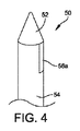
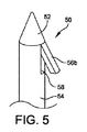
一部の実施例において、第2骨の中の逆カウンターシンクは、槌状足指インプラント2を第2骨の中に挿入する前に道具により形成される。図4および図5は第2骨の中に逆カウンターシンクを形成するように構成された道具50の一実施例を例示する。道具50は、シャフト54に結合された道具先端52を含む。シャフト54は、一体に形成された切断エッジ56を有する。切断エッジ56は、陥没状態(図4に図示)から配置状態(図5に図示)まで配置可能である。切断エッジ56は、例えば、機械的配置メカニズム、ヒンジ型配置メカニズム、および/または如何なる他の適切な配置メカニズムのような如何なる適切な配置メカニズムを含むことができる。シャフト54は、切断エッジ56を収容するように構成された空洞58を含み、切断エッジ56は、陥没位置のシャフト54と同じ高さにある。一部の実施例において、一つ以上の追加切断エッジ56は、シャフト54と一体に形成され、同時に配置されることができる。一部の実施例において、道具50のシャフト54の直径は、陥没位置の槌状足指インプラント2の拡張可能部10の直径と実質的に同一である。切断エッジ56は、配置位置の槌状足指インプラント2の拡張可能部10の直径と実質的に同一またはこの直径よりも小さい直径を有する逆カウンターシンクを形成するように構成される。逆カウンターシンクは、槌状足指インプラント2の拡張可能部10のための軸受表面を提供する。
In some embodiments, the reverse countersink in the second bone is formed by a tool prior to inserting the saddle-shaped
図6は図4の切断道具が挿入された第2骨62の一実施例を図示する。道具50は、第2骨62の中に形成された管65内に第1所定の深さに挿入される。道具先端52およびシャフト54は、切断エッジ56を第2骨62の中の第2所定の深さに位置させる。切断エッジ56は、挿入に適切な陥没位置(図4に図示)から管を介して配置位置(図5に図示)まで配置される。道具50は、中心軸で回転されて切断エッジ56が第2骨62の中に逆カウンターシンク66を形成する。切断エッジ56は、骨が道具50の回転の間に切断エッジ56により除去されることによって部分配置位置から完全配置位置まで遷移されることができる。切断エッジ56が円錐状逆カウンターシンク66を形成するように構成されるが、切断エッジ56が、例えば、円錐、正方形、または円筒状カウンターシンクのような如何なる適切な空洞を形成するように構成されることができるという点が理解されるであろう。逆カウンターシンク66を形成した後、切断エッジ56は、配置位置から陥没位置まで遷移され、道具50は、管65から除去される。
FIG. 6 illustrates one embodiment of the
図7は第1骨60に固定され、第2骨62の中に部分的に挿入された槌状足指インプラント2を例示する。槌状足指インプラント2の第1端部4は、ねじ山部12により第1骨60に結合される。ねじ山部12は、第1骨60の中に形成された管68内に挿入される。管68は、例えば、ドリル、K‐鋼線、および/または他の適切な装置により第1骨60の中に予め穿孔されることができ、および/またはねじ山部12の挿入の間に槌状足指インプラント2により形成されることができる。ねじ山部12は、第1骨60の中で所定の穿孔深さに延びる。一部の実施例において、ねじ山部12は、第1骨60の実質的な全幅に延びることができる。一部の実施例において、ねじ山部12は、シャフト6の一部が管68内に位置する深さに挿入される。拡張可能部10は、第1端部4の第1骨60の中への挿入の間に陥没位置で維持される。拡張可能部10は、例えば、拡張可能部10上に配置されたスリーブ(図18参照)により陥没位置で維持されることができる。
FIG. 7 illustrates the hooked
槌状足指インプラント2を第1骨60に結合した後、槌状足指インプラント2の第2端部8は、第2骨62の中に挿入される。拡張可能部10は、第2骨62の中に形成された管65内に挿入される。管65は、挿入の間に陥没位置で拡張可能アーム10a〜10dを維持する力を拡張可能部10に加えて拡張可能部10が管65を横断することを許容する。槌状足指インプラント2が骨62の中に完全に挿入されないため、第1骨60と第2骨62との間にギャップが存在する。
After coupling the saddle-
第1長さ「A」は、逆カウンターシンクの表面を有する図7に例示された初期位置から拡張可能端部10の移動距離を例示する。第2長さ「B」は、第1骨60と第2骨62との間の対応するギャップを例示する。インプラント2が挿入されるときに長さ「B」と実質的に同一の距離「A」を有することは、関節が完全に閉鎖されることを保証する。
The first length “A” illustrates the travel distance of the
図8は第2骨62の中に完全に挿入された槌状足指インプラント2を例示する。第1骨60および第2骨62は整列され、その間の関節は閉鎖されて、拡張可能部10を第2骨62の中に形成された逆カウンターシンク66内に圧入させる。図8に図示されるように、拡張可能アーム10a〜10dは、逆カウンターシンク66内に完全に挿入されるときに配置位置に拡張される。拡張可能アーム10a〜10dは、管65を越えて拡張され、逆カウンターシンク66の軸受表面を締結するのに十分な配置直径を有する。逆カウンターシンク66は、拡張可能部10が最小空間を有するか如何なる追加空間を有することなく逆カウンターシンク内に嵌合して固定位置で槌状足指インプラント2を維持するようにサイズ設定される。一部の実施例において、拡張可能アーム10a〜10dは、逆カウンターシンク66の直径と同一の拡張直径を含む。一部の実施例において、拡張可能アーム10a〜10dは、逆カウンターシンク66の直径よりも大きい直径に偏向されて拡張可能アーム10a〜10dが逆カウンターシンク66の内部壁と接触することを許容する。
FIG. 8 illustrates the saddle-shaped
図9は逆カウンターシンク66内に挿入された拡張可能部10の分離図を例示する。図示されているように、拡張可能アーム10a〜10dは、逆カウンターシンク66の直径と実質的に同一の直径に拡張される。一部の実施例において、拡張可能アーム10a〜10dは、空洞66の直径よりも大きい直径に偏向されて拡張可能アーム10a〜10dがカウンターシンク66の全体直径に拡張されることを保証する。逆カウンターシンク66は、設置後に槌状足指インプラント2の移動を防止するために最小余裕空間を有する拡張可能部10を収容するようにサイズ設定および構成される。逆カウンターシンク66が円錐状空洞に図示されているが、逆カウンターシンク66は、拡張構成で拡張可能部10の形状に対応する如何なる適切な形状を含むことができる。
FIG. 9 illustrates an isolated view of the
図6〜図9および図20を参照すると、第1骨60および第2骨62を結合するための方法600が論議される。第1ステップ602において、管68は、第1骨60の中に形成される。管68は、槌状足指インプラント2の第1端部4を収容するようにサイズ設定および構成される。第2ステップ604において、管65は、第2骨62の中に形成される。第2骨62の中の管65は、道具50を収容するようにサイズ設定および構成される。道具50は、第2骨62の中に逆カウンターシンク66を形成するように構成される。第1骨60の中の管68および/または第2骨62の中の管65は、例えば、K‐鋼線、ドリルおよび/または如何なる他の適切な装置を使用して形成されることができる。一部の実施例において、第1骨60は基節骨を含み、第2骨62は中節骨を含む。
With reference to FIGS. 6-9 and 20, a method 600 for joining the
第3ステップ606において、道具50は、第2骨62の中に形成された管65内に挿入される。道具50は、道具先端52と、シャフト54と、を含む。道具50は、管65内で第1所定の深さに挿入される。一部の実施例において、道具先端52が管の閉鎖端部と接触するまで道具50が挿入される。他の実施例において、道具先端52は、道具52上に現れた第1所定の深さに挿入される。配置可能切断エッジ56は、シャフト54に結合される。道具先端52およびシャフト54は、管65内で第2所定の深さに切断エッジ56を位置させるように構成される。第4ステップ608において、切断エッジ56が配置され、道具50は、中心軸で回転されて、第4ステップ608の間に第2骨の中に逆カウンターシンク66を形成する。逆カウンターシンク66を形成した後、切断エッジ56は、シャフト54に対して陥没され、第5ステップ610において、道具50は、管65から除去される。
In a
第6ステップ612において、スリーブ(図18参照)は、槌状足指インプラント2の拡張可能部10上に配置される。スリーブは、拡張可能部10を圧縮し、槌状足指インプラント2を回転させるためのハンドルを提供するように構成される。一部の実施例において、第6ステップ612が省略される。第7ステップ614において、槌状足指インプラント2の第1端部4は、第1骨60の中に形成された管68内に挿入される。槌状足指インプラント2は、例えば、ねじ山部12を管68と回転可能に接するようにすることで挿入されることができる。槌状足指インプラント2は、第1骨60の中で所定の深さに挿入される。所定の深さは、ねじ山部12の長さに対応することができる。一部の実施例において、ねじ山部12は、第1骨60の全幅を介して実質的に延びるように構成される。一部の実施例において、シャフト6の一部は、管68内に挿入される。
In a
第1端部4が第1骨60の中に挿入された後、槌状足指インプラント2の第2端部4は、第8ステップ616の間に第2骨62の中に挿入される。陥没位置で拡張可能アーム10a〜10dを維持するためにスリーブが拡張可能部10上に配置されると、スリーブは、第2端部4を第2骨の中に挿入する前に除去される。一部の実施例において、拡張可能アーム10a〜10dは、拡張位置に偏向される。
After the first end 4 is inserted into the
拡張可能部10は、第2骨62の中に形成された管65内に挿入される。管65は、拡張可能アーム10a〜10d上に力を加え、拡張可能アーム10a〜10dを陥没位置で圧入させる。陥没位置で、拡張可能部10は、管65を介して嵌合するようにサイズ設定および構成される。例えば、一部の実施例において、拡張可能アーム10a〜10dは、管65の内径と同一またはより小さい直径を陥没位置で有する。拡張可能部10は、管65を介して第2骨62の中に形成された逆カウンターシンク66に挿入される。第9ステップ618において、拡張可能アーム10a〜10dは、図8〜図9に図示されるように、拡張構成を仮定する。拡張可能アーム10a〜10dは、第2骨62の中に形成された逆カウンターシンク66の軸受表面と接する。一部の実施例において、槌状足指インプラント2の逆カウンターシンク66および拡張可能部10は、拡張可能ヘッド10を逆カウンターシンク66内に挿入した後、槌状足指インプラント2の移動を防止するようにサイズ設定および構成される。
The
図10〜図16は第1骨60および第2骨62を接合するためのインプラントの追加実施例を例示する。図10〜図11は第1拡張可能アーム110aおよび第2拡張可能アーム110bを有する拡張可能部110を含むインプラント102の一実施例を例示する。他の実施例において、インプラント102は、図1〜図9と関連して記載した槌状足指インプラント2と類似する。インプラント102は、例えば、基節骨および中節骨のような第1骨60および第2骨62を結合するように構成される。図10は正方形シャフト106aを有するインプラント102の一実施例を例示する。図11は円筒状シャトプ106bを有するインプラント102の一実施例を例示する。当業者は、シャフト106が如何なる適切な断面形状を含むことができることを認知するであろう。
10-16 illustrate additional examples of implants for joining the
図12〜図16はシャフト206,306により結合された第1拡張可能部204a,304aと、第2拡張可能部204b,304bと、を含む槌状足指インプラント202,302の実施例を例示する。図12〜図14は正方形シャフト206により結合された第1拡張可能部204aおよび第2拡張可能部204bを有するインプラント202の一実施例を例示する。第1および第2拡張可能部204a,204bそれぞれは、複数の拡張可能アーム210a〜210d,214a〜214dを含む。拡張可能アーム210a〜210d,214a〜214dは、図12および図13で陥没位置に例示される。図14は拡張可能アーム210a〜210d,214a〜214dを拡張位置で例示する。拡張可能部204a,204bは、図1〜図9と関連して論議された拡張可能部10と類似する。図15および図16は円筒状シャフト306により結合された第1拡張可能部304aと第2拡張可能部304bとを含むインプラント302の一実施例を例示する。拡張可能部304a,304bそれぞれは、複数の拡張可能アーム310a〜310d,314a〜314dを含む。
FIGS. 12-16 illustrate an example of a saddle-shaped
インプラント202,302は、第1骨を第2骨に、例えば、中節骨を基節骨に接合するように構成される。図17は第1骨360および第2骨364を結合するインプラント302の一実施例を例示する。逆カウンターシンク366a,366bを含む管365a,365bは、第1骨360および第2骨362それぞれに形成される。逆カウンターシンク366a,366bは、例えば、図4〜図6とともに記載された道具50により形成されることができる。インプラント302の第1端部304aは、陥没状態で第1骨360の管365a内に挿入される。一部の実施例において、管365aは、拡張可能アーム310a〜310d上に力を加えて、管365aを介して摺動自在に遷移するようにサイズ設定および構成された拡張可能アーム310a〜310dを陥没位置で維持する。拡張可能部304aが逆カウンターシンク366aに至るときに、拡張可能アーム310a〜310dは拡張され、逆カウンターシンク366aの軸受表面を締結して第1骨360でインプラント302を維持する。
The
インプラント302の第2拡張可能部304bは、第2骨362の中に形成された管365b内に挿入される。管365bは、逆カウンターシンク366bを含む。インプラント302の第2端部304bは、陥没状態で第2骨362の管365b内に挿入される。一部の実施例において、管365bは、インプラント302の挿入の間に陥没状態で拡張可能アーム314a〜314dを圧入させて第2端部304bが管365bを横断することを許容する。第2拡張可能部304bが逆カウンターシンク366bに至るときに、拡張可能アーム314a〜314dは配置位置に拡張され、逆カウンターシンク366bの軸受表面を締結する。第1骨360および第2骨362は整列され、インプラント302により維持される。
The second
図12〜図17および図21を参照すると、第1骨60および第2骨62を結合するための方法650が論議される。第1ステップ652において、管68は、第1骨60の中に形成される。第2ステップ654において、管65は、第2骨62の中に形成される。管65および68は、道具50を収容するようにサイズ設定および構成される。道具50は、第1骨60および第2骨62それぞれに逆カウンターシンク66を形成するように構成される。第1骨60の中の管68および/または第2骨62の中の管65は、例えば、K‐鋼線、ドリルおよび/または如何なる他の適切な装置を使用して形成されることができる。一部の実施例において、第1骨60は基節骨を含み、第2骨62は中節骨を含む。
With reference to FIGS. 12-17 and 21, a method 650 for joining the
第3ステップ656において、道具50は、第2骨62の中に形成された管65内に挿入される。道具50は、道具先端52とシャフト54とを含む。道具50は、管65内に第1所定の深さに挿入される。一部の実施例において、道具先端52が管の閉鎖端部と接触するまで道具50が挿入される。他の実施例において、道具先端52は、道具52上に現れた第1所定の深さに挿入される。配置可能切断エッジ56は、シャフト54に結合される。道具先端52およびシャフト54は、管65内で第2所定の深さに切断エッジ56を位置させるように構成される。第4ステップ658において、切断エッジ56が配置され、道具50は中心軸で回転されて、第4ステップ608の間に第2骨の中に逆カウンターシンク66を形成する。逆カウンターシンク66を形成した後、切断エッジ56は、シャフト54に対して陥没され、第5ステップ660において、道具50は、管65から除去される。第6ステップ662において、道具は、第1骨60の中に形成された管68内に挿入され、配置可能切断エッジ56が配置され、逆カウンターシンクは、第1骨60の中に形成される。配置可能切断エッジ56は、第1骨の中に逆カウンターシンクを形成した後、シャフト54に対して陥没され、道具50は、第1骨60から除去される。
In a
第7ステップ664において、スリーブ(図18参照)は、槌状足指インプラント202の第2拡張可能部214上に配置される。スリーブは、第2拡張可能部214を圧縮し、槌状足指インプラント2を把持するためのハンドルを提供するように構成される。一部の実施例において、第6ステップ612が省略される。第8ステップ666において、槌状足指インプラント2の第1拡張可能端部210は、第1骨60の中に形成された管68内に挿入される。管68は、拡張可能アーム210a〜210d上に力を加え、拡張可能アーム210a〜210dを陥没位置に圧入させる。陥没位置で、拡張可能部210は、管68を介して嵌合するようにサイズ設定および構成される。例えば、一部の実施例において、拡張可能アーム210a〜210dは、管68の内径と同一またはより小さい直径を陥没位置で有する。拡張可能部210は、管68を介して第1骨60の中に形成された逆カウンターシンクに挿入される。第9ステップ668において、拡張可能アーム210a〜210dは、拡張構成を仮定する。拡張可能アーム210a〜210dは、第1骨60の中に形成された逆カウンターシンクの軸受表面と接する。一部の実施例において、逆カウンターシンクおよび槌状足指インプラント202の拡張可能部210は、拡張可能ヘッド210を逆カウンターシンク内に挿入した後、槌状足指インプラント202の移動を防止するようにサイズ設定および構成される。
In a seventh step 664, the sleeve (see FIG. 18) is placed on the second expandable portion 214 of the saddle-shaped
第1拡張可能部210が第1骨60の中に挿入された後、槌状足指インプラント202の第2拡張可能部214は、第3ステップ670の間に第2骨62の中に挿入される。スリーブが拡張可能部214上に配置されて陥没位置で拡張可能アーム214a〜214dを維持すると、スリーブは、挿入の前に除去される。一部の実施例において、拡張可能アーム214a〜214dは、拡張位置に偏向される。
After the first
第2拡張可能部214は、第2骨62の中に形成された管65内に挿入される。管65は、拡張可能アーム214a〜214d上に力を加え、拡張可能アーム214a〜214dを陥没位置に圧入させる。陥没位置で、第2拡張可能部214は、管65を介して嵌合されるようにサイズ設定および構成される。例えば、一部の実施例において、拡張可能アーム214a〜214dは、管65の内径と同一またはより小さい直径を陥没位置で有する。第2拡張可能部214は、管65を介して第2骨62の中に形成された逆カウンターシンク66に挿入される。第11ステップ672において、拡張可能アーム214a〜214dは、拡張構成を仮定する。拡張可能アーム214a〜214dは、第2骨62の中に形成された逆カウンターシンク66の軸受表面と接する。一部の実施例において、逆カウンターシンク66および槌状足指インプラント202の第2拡張可能部214は、第2拡張可能部214を逆カウンターシンク66内に挿入した後、槌状足指インプラント202の移動を防止するようにサイズ設定および構成される。
The second expandable portion 214 is inserted into a
図18は槌状足指インプラントの一つ以上の実施例を挿入するように構成されたスリーブおよびドライバーの組み合わせの一実施例を例示する。例えば、一部の実施例において、スリーブおよびドライバーの組み合わせ400は、図1〜図17に例示された槌状足指インプラント2、102、202、302とともに使用されるように構成される。スリーブおよびドライバーの組み合わせ400は、インプラント2の拡張可能部10を収容するように構成されたチャネル404を規定する縦方向スリーブ402を含む。拡張可能部10の拡張可能特徴部10a〜10dは、チャネル404によりインプラント2に対して圧縮され、陥没位置で維持される。スリーブおよびドライバーの組み合わせ400は、ドライバーヘッド406を含む。ドライバーヘッド406は、インプラント2を前進させるためにスリーブおよびドライバーの組み合わせ400をハンドルに取付けるように構成された迅速連結特徴部408を含むことができる。迅速連結特徴部408およびハンドルは、第1端部4を第1骨に結合するために並進、回転、および/または如何なる他の適切な移動を提供するように構成されることができる。一部の実施例において、チャネル404の内部メイティング(mating)特徴部は、回転制御を提供してインプラント2が近位に前進したり遠位に後進することができる。例えば、一実施例において、拡張可能特徴部10a〜10dおよびチャネル404は、逆フィリップヘッド交差面のように作動する。図19はスリーブおよびドライバーの組み合わせ500の代案の実施例を例示する。図19の実施例において、チャネル504は、拡張可能側面10の拡張可能特徴部10a〜10dを収容するためのより広い開口部および円形エッジを含む。
FIG. 18 illustrates one embodiment of a sleeve and driver combination configured to insert one or more embodiments of saddle-shaped toe implants. For example, in some embodiments, the sleeve and
一部の実施例において、骨インプラントが開示される。骨インプラントは、第1骨に結合されるように構成された第1端部と、少なくとも一つの拡張可能特徴部を含む第1拡張可能部を規定する第2端部と、第1端部と第2端部との間で縦方向に延びる長方形シャフトと、を含む。第1拡張可能部は、陥没状態で第2骨の中に形成された逆カウンターシンク内に収容されるようにサイズ設定および構成される。第1拡張可能部は、逆カウンターシンク内で拡張されて少なくとも一つの拡張可能特徴部が逆カウンターシンクの軸受表面に結合される。 In some examples, a bone implant is disclosed. The bone implant includes a first end configured to be coupled to the first bone, a second end defining a first expandable portion including at least one expandable feature, and a first end. A rectangular shaft extending longitudinally between the second end. The first expandable portion is sized and configured to be received in a reverse countersink formed in the second bone in a depressed state. The first expandable portion is expanded within the reverse countersink and at least one expandable feature is coupled to the bearing surface of the reverse countersink.
一部の実施例において、第1拡張可能部は、複数の拡張可能アームを含む。
一部の実施例において、拡張可能部は、4個の拡張可能アームを含む。
In some embodiments, the first expandable portion includes a plurality of expandable arms.
In some embodiments, the expandable portion includes four expandable arms.
一部の実施例において、第1端部は、ねじ山部を含む。
一部の実施例において、ねじ山部は、第1骨の厚さを介して延びるに十分な長さを含む。
In some embodiments, the first end includes a thread.
In some embodiments, the thread includes a length sufficient to extend through the thickness of the first bone.
一部の実施例において、第1端部は、少なくとも一つの拡張可能特徴部を含む第2拡張可能部を規定する。第2拡張可能部は、陥没状態で第1骨の中に形成された逆カウンターシンク内に収容されるように構成される。第2拡張可能部は、逆カウンターシンク内で拡張され、少なくとも一つの拡張可能特徴部は、逆カウンターシンクの軸受表面に結合される。 In some embodiments, the first end defines a second expandable portion that includes at least one expandable feature. The second expandable portion is configured to be housed in a reverse counter sink formed in the first bone in a depressed state. The second expandable portion is expanded within the reverse countersink, and at least one expandable feature is coupled to the bearing surface of the reverse countersink.
一部の実施例において、第2拡張可能部は、複数の拡張可能アームを含む。
一部の実施例において、第1拡張可能部は、ニチノール、チタン、合金、およびステンレス鋼からなる群から選択される材料を含む。
In some embodiments, the second expandable portion includes a plurality of expandable arms.
In some embodiments, the first expandable portion comprises a material selected from the group consisting of nitinol, titanium, an alloy, and stainless steel.
一部の実施例において、第1骨は基節骨を含み、第2骨は中節骨を含む。
一部の実施例において、細長いシャフトは、所定の長さで延び、第1端部が第1骨の中に完全に挿入され、第2端部が第2骨の中に完全に挿入されるときに第1骨と第2骨との間に実質的にギャップがない。
In some embodiments, the first bone includes a proximal phalanx and the second bone includes a middle phalanx.
In some embodiments, the elongate shaft extends a predetermined length such that the first end is fully inserted into the first bone and the second end is fully inserted into the second bone. Sometimes there is substantially no gap between the first bone and the second bone.
一部の実施例において、手術道具が開示される。手術道具は、骨の中に形成された管内に収容されるようにサイズ設定および構成されたシャフトと、シャフトと一体に形成された少なくとも一つの切断エッジと、を含む、拡張可能切断エッジは、管内への挿入のために構成された陥没位置と、管内に逆カウンターシンクを形成するように構成された拡張位置と、を含む。拡張可能切断エッジは、管内に挿入された後に拡張位置に配置される。 In some embodiments, a surgical tool is disclosed. The surgical tool includes a shaft sized and configured to be received within a tube formed in the bone, and at least one cutting edge integrally formed with the shaft, the expandable cutting edge comprises: A depressed position configured for insertion into the tube and an expanded position configured to form a reverse countersink within the tube. The expandable cutting edge is placed in the expanded position after being inserted into the tube.
一部の実施例において、手術道具は、管の端部と接触し、管の端部から所定の長さで拡張可能切断エッジを離隔させるように構成された円錐状ヘッドを含む。 In some embodiments, the surgical tool includes a conical head configured to contact the end of the tube and separate the expandable cutting edge by a predetermined length from the end of the tube.
一部の実施例において、少なくとも一つの拡張可能切断エッジは、機械的屈曲により配置される。 In some embodiments, at least one expandable cutting edge is disposed by mechanical bending.
一部の実施例において、少なくとも一つの拡張可能切断エッジは、ヒンジを含む。
一部の実施例において、少なくとも一つの拡張可能切断エッジは、シャフトが回転するときに逆カウンターシンクを形成するように構成される。
In some embodiments, the at least one expandable cutting edge includes a hinge.
In some embodiments, the at least one expandable cutting edge is configured to form a reverse countersink when the shaft rotates.
一部の実施例において、槌状足指を校正するための方法が開示される。方法は、第1骨の中に第1管を形成するステップと、第2骨の中に第2管を形成するステップと、第2管内に手術道具を挿入するステップと、手術道具を回転させて第2骨の第2管内に逆カウンターシンクを形成するステップと、を含む。手術道具は、シャフトと、シャフトの第1端部に位置したヘッドと、シャフトと一体に形成され、陥没位置から拡張位置まで配置可能な拡張可能切断エッジと、を含む。 In some embodiments, a method for calibrating a saddle toe is disclosed. The method includes forming a first tube in the first bone, forming a second tube in the second bone, inserting a surgical tool into the second tube, and rotating the surgical tool. Forming a reverse countersink in the second tube of the second bone. The surgical tool includes a shaft, a head located at the first end of the shaft, and an expandable cutting edge that is integrally formed with the shaft and can be placed from a depressed position to an expanded position.
一部の実施例において、方法は、インプラントの第1端部を第1骨の中の第1管内に挿入するステップをさらに含む。 In some examples, the method further includes inserting the first end of the implant into the first tube in the first bone.
一部の実施例において、方法は、インプラントの第2端部を第2骨の中の第2管内に挿入するステップをさらに含む。インプラントの第2端部は、拡張可能部を含み、拡張可能部は、少なくとも一つの拡張可能特徴部を含む。拡張可能部は、陥没位置で第2管を介して逆カウンターシンクに挿入される。少なくとも一つの拡張可能特徴部は、逆カウンターシンク内で拡張され、少なくとも一つの拡張可能特徴部は、逆カウンターシンクの軸受表面に結合される。 In some embodiments, the method further includes inserting the second end of the implant into a second tube in the second bone. The second end of the implant includes an expandable portion, and the expandable portion includes at least one expandable feature. The expandable part is inserted into the reverse counter sink via the second tube at the depressed position. At least one expandable feature is expanded within the reverse countersink, and at least one expandable feature is coupled to the bearing surface of the reverse countersink.
一部の実施例において、管は、拡張可能部上に力を加えて挿入の間に陥没状態で拡張可能部を維持する。少なくとも一つの拡張可能特徴部は、逆カウンターシンク内に完全に挿入されるときに配置される。 In some embodiments, the tube applies a force on the expandable portion to maintain the expandable portion in a collapsed state during insertion. At least one expandable feature is disposed when fully inserted into the reverse countersink.
一部の実施例において、インプラントの第1端部は、ねじ山部を含む。インプラントの第1端部を挿入するステップは、ねじ山部を回転させて第1管と締結するステップを含む。 In some embodiments, the first end of the implant includes a thread. Inserting the first end of the implant includes rotating the thread to fasten with the first tube.
一部の実施例において、槌状足指インプラントを校正するための方法が開示される。方法は、第1骨の中に第1管を形成するステップと、第2骨の中に第2管を形成するステップと、手術道具を第1管内に挿入するステップと、を含む。手術道具は、シャフトと、シャフトの第1端部に位置したヘッドと、シャフトと一体に形成され、陥没位置から拡張位置まで配置可能な拡張可能切断エッジと、を含む。方法は、手術道具を回転させて第1骨の第1管内に逆カウンターシンクを形成するステップと、手術道具を第2管内に挿入するステップと、手術道具を回転させて第2骨の第2管内に逆カウンターシンクを形成するステップと、をさらに含む。 In some embodiments, a method for calibrating a saddle toe implant is disclosed. The method includes forming a first tube in the first bone, forming a second tube in the second bone, and inserting a surgical tool into the first tube. The surgical tool includes a shaft, a head located at the first end of the shaft, and an expandable cutting edge that is integrally formed with the shaft and can be placed from a depressed position to an expanded position. The method includes rotating the surgical tool to form a reverse countersink in the first tube of the first bone, inserting the surgical tool into the second tube, and rotating the surgical tool to rotate the second of the second bone. Forming a reverse countersink in the tube.
一部の実施例において、方法は、インプラントの第1端部を第1骨の中の第1管内に挿入するステップをさらに含む。インプラントの第1端部は、少なくとも一つの拡張可能特徴部を有する第1拡張可能部を含む。第1拡張可能部は、陥没位置で第1管を介して逆カウンターシンクに挿入される。少なくとも一つの拡張可能特徴部は、逆カウンターシンク内で拡張されて、少なくとも一つの拡張可能特徴部は、逆カウンターシンクの軸受表面に結合される。 In some examples, the method further includes inserting the first end of the implant into the first tube in the first bone. The first end of the implant includes a first expandable portion having at least one expandable feature. The first expandable portion is inserted into the reverse counter sink via the first tube at the depressed position. At least one expandable feature is expanded within the reverse countersink, and the at least one expandable feature is coupled to the bearing surface of the reverse countersink.
一部の実施例において、第1管は、第1拡張可能部上に力を加えて、挿入の間に陥没状態で第1拡張可能部を維持する。少なくとも一つの拡張可能特徴部は、逆カウンターシンク内に完全に挿入されるときに配置される。 In some embodiments, the first tube applies a force on the first expandable portion to maintain the first expandable portion in a collapsed state during insertion. At least one expandable feature is disposed when fully inserted into the reverse countersink.
一部の実施例において、方法は、インプラントの第2端部を第2骨の中の第2管内に挿入するステップをさらに含む。インプラントの第2端部は、少なくとも一つの拡張可能特徴部を有する第2拡張可能部を含む。第2拡張可能部は、陥没位置で第2管を介して逆カウンターシンク内に挿入される。少なくとも一つの拡張可能特徴部は、逆カウンターシンク内で拡張されて、少なくとも一つの拡張可能特徴部は、逆カウンターシンクの軸受表面に結合される。 In some embodiments, the method further includes inserting the second end of the implant into a second tube in the second bone. The second end of the implant includes a second expandable portion having at least one expandable feature. The second expandable part is inserted into the counter-counter sink via the second tube at the depressed position. At least one expandable feature is expanded within the reverse countersink, and the at least one expandable feature is coupled to the bearing surface of the reverse countersink.
一部の実施例において、第2管は、第2拡張可能部上に力を加えて、挿入の間に陥没状態で第2拡張可能部を維持する。少なくとも一つの拡張可能特徴部は、逆カウンターシンク内に完全に挿入されるときに配置される。 In some embodiments, the second tube applies a force on the second expandable portion to maintain the second expandable portion in a collapsed state during insertion. At least one expandable feature is disposed when fully inserted into the reverse countersink.
本発明対象が例示的な実施例について記載しているが、本発明は、これに制限されない。むしろ、別添の請求項は、当業者により行われうる他の変形および実施例を含むように広範に解釈されるべきである。 Although the subject matter of the invention has been described with reference to exemplary embodiments, the invention is not limited thereto. Rather, the appended claims should be construed broadly to include other variations and embodiments that can be made by those skilled in the art.
Claims (10)
少なくとも一つの拡張可能特徴部を含む第1拡張可能部を規定する第2端部であって、前記第1拡張可能部は、陥没状態で第2骨の中に形成された逆カウンターシンク内に収容されるようにサイズ設定および構成され、前記第1拡張可能部は、前記逆カウンターシンク内で拡張され、前記少なくとも一つの拡張可能特徴部は、前記逆カウンターシンクの軸受表面に結合される第2端部と、
前記第1端部と前記第2端部との間で縦方向に延びる細長いシャフトと、を含む、骨インプラント。 A first end configured to be coupled to the first bone;
A second end defining a first expandable portion including at least one expandable feature, wherein the first expandable portion is in a reverse countersink formed in the second bone in a depressed state Sized and configured to be received, the first expandable portion is expanded within the counter-counter sink, and the at least one expandable feature is coupled to a bearing surface of the counter-counter sink. Two ends,
A bone implant comprising an elongate shaft extending longitudinally between the first end and the second end.
Applications Claiming Priority (1)
| Application Number | Priority Date | Filing Date | Title |
|---|---|---|---|
| PCT/US2014/056315 WO2016043751A1 (en) | 2014-09-18 | 2014-09-18 | Hammertoe implant and instrument |
Publications (3)
| Publication Number | Publication Date |
|---|---|
| JP2017501832A JP2017501832A (en) | 2017-01-19 |
| JP2017501832A5 JP2017501832A5 (en) | 2017-08-24 |
| JP6235724B2 true JP6235724B2 (en) | 2017-11-22 |
Family
ID=55521933
Family Applications (1)
| Application Number | Title | Priority Date | Filing Date |
|---|---|---|---|
| JP2016544828A Expired - Fee Related JP6235724B2 (en) | 2014-09-18 | 2014-09-18 | Spider toe implant and tool |
Country Status (7)
| Country | Link |
|---|---|
| US (2) | US9808296B2 (en) |
| EP (1) | EP3193788A4 (en) |
| JP (1) | JP6235724B2 (en) |
| CN (1) | CN105764449A (en) |
| AU (2) | AU2014331633B2 (en) |
| CA (1) | CA2887570C (en) |
| WO (1) | WO2016043751A1 (en) |
Families Citing this family (18)
| Publication number | Priority date | Publication date | Assignee | Title |
|---|---|---|---|---|
| US9498273B2 (en) | 2010-06-02 | 2016-11-22 | Wright Medical Technology, Inc. | Orthopedic implant kit |
| US8608785B2 (en) | 2010-06-02 | 2013-12-17 | Wright Medical Technology, Inc. | Hammer toe implant with expansion portion for retrograde approach |
| US9724138B2 (en) | 2011-09-22 | 2017-08-08 | Arthrex, Inc. | Intermedullary devices for generating and applying compression within a body |
| US9554914B2 (en) * | 2011-12-12 | 2017-01-31 | Wright Medical Technology, Inc. | Fusion implant |
| US8945232B2 (en) | 2012-12-31 | 2015-02-03 | Wright Medical Technology, Inc. | Ball and socket implants for correction of hammer toes and claw toes |
| US9522022B2 (en) * | 2013-11-18 | 2016-12-20 | Biomedical Enterprises, Inc. | Method and appparatus for an intramedullary implant and method of implantation therefor |
| JP6235724B2 (en) * | 2014-09-18 | 2017-11-22 | ライト メディカル テクノロジー インコーポレイテッドWright Medical Technology, Inc. | Spider toe implant and tool |
| CN105960211B (en) | 2014-12-19 | 2019-01-11 | 瑞特医疗技术公司 | For anchor log in the marrow of interphalangeal arthrodesis of toe |
| US20160296342A1 (en) * | 2015-04-08 | 2016-10-13 | K2M, Inc. | Flexible spinal fixation device |
| US10292745B2 (en) | 2015-10-07 | 2019-05-21 | Arthrex, Inc. | Devices for generating and applying compression within a body |
| EP3397180A1 (en) * | 2015-12-28 | 2018-11-07 | Glenhurst Labs, LLC | Surgical devices for small bone fracture surgery |
| EP3758633A4 (en) * | 2018-03-01 | 2022-02-09 | Paragon 28, Inc. | Implants and methods of use and assembly |
| US11246712B2 (en) * | 2018-03-01 | 2022-02-15 | Paragon 28, Inc. | Implants, systems, and methods of use and assembly |
| WO2020036865A1 (en) * | 2018-08-14 | 2020-02-20 | Arthrex, Inc. | Intramedullary implant systems and methods |
| US11504172B2 (en) * | 2018-11-01 | 2022-11-22 | Arthrex, Inc. | Variable stiffness hammertoe K-wire and methods for use |
| WO2021231329A1 (en) | 2020-05-11 | 2021-11-18 | Gensano Llc | Cannulated bone implant |
| CN111839654B (en) * | 2020-07-24 | 2022-05-20 | 中南大学湘雅医院 | Guide positioning type electric bone drill |
| CN113476130A (en) * | 2021-07-26 | 2021-10-08 | 宁波兆盈医疗器械有限公司 | Fuse bone nail |
Family Cites Families (513)
| Publication number | Priority date | Publication date | Assignee | Title |
|---|---|---|---|---|
| US430236A (en) | 1890-06-17 | Island | ||
| US373074A (en) | 1887-11-15 | Wood-screw | ||
| US346148A (en) | 1886-07-27 | Daniel p | ||
| US882937A (en) | 1908-03-24 | North Bros M F G Co | Screw-eye driver. | |
| US561968A (en) | 1896-06-16 | Georges cotjlon | ||
| US348589A (en) | 1886-09-07 | sloan | ||
| US321389A (en) | 1885-06-30 | Combined nail and screw | ||
| US736121A (en) | 1902-04-21 | 1903-08-11 | Abraham B Lipscomb | Boot-calk. |
| US821025A (en) | 1903-01-27 | 1906-05-22 | Joseph Bartlett Davies | Nail or screw for securing corrugated iron. |
| GB140983A (en) | 1919-10-27 | 1920-04-08 | Charles Louis Basham | Improvements in wood screws |
| US1966835A (en) | 1932-01-28 | 1934-07-17 | Dardelet Threadlock Corp | Fastening means |
| FR736058A (en) | 1932-04-28 | 1932-11-18 | Improvements made to bolts to ensure the safety of assemblies | |
| US2140749A (en) | 1936-08-05 | 1938-12-20 | Filshie Lead Head Nail Company | Capped nail |
| US2361107A (en) | 1944-03-08 | 1944-10-24 | Charles E Johnson | Self-locking valve tappet screw |
| US2451747A (en) | 1945-03-23 | 1948-10-19 | Ernest T Kindt | Doweled structure |
| US2490364A (en) | 1948-02-27 | 1949-12-06 | Herman H Livingston | Bone pin |
| US2600517A (en) | 1948-09-29 | 1952-06-17 | Herschel L Rushing | Tell-tale screw spike |
| FR1036978A (en) | 1951-05-11 | 1953-09-14 | Karcher Schraubenwerke G M B H | Bolt |
| US2697370A (en) | 1951-09-04 | 1954-12-21 | Linzy W Brooks | Ratchet type socket wrench |
| US2895368A (en) | 1955-01-21 | 1959-07-21 | Jr Paul R Trigg | Bolt having rolled grooves and recessed head to enhance uniform elongation |
| US2832245A (en) | 1956-02-15 | 1958-04-29 | Burrows Allen | Sponge-rubber liner for socket wrench |
| US3466669A (en) | 1966-09-20 | 1969-09-16 | Univ Iowa | Intramedullary finger joint prosthesis |
| NL132715C (en) | 1967-01-06 | |||
| US3593342A (en) | 1969-01-27 | 1971-07-20 | Cutter Lab | Prosthetic joint |
| US3681786A (en) | 1970-07-13 | 1972-08-08 | Medical Eng Corp | Solid human prosthesis of varying consistency |
| GB1320956A (en) | 1970-10-09 | 1973-06-20 | St Peters Research Ltd | Prosthetic joints |
| DE2109162B1 (en) | 1971-02-26 | 1972-05-25 | Fischer Artur | Sleeve-shaped support element for long bone fractures |
| DE2112138B1 (en) | 1971-03-13 | 1972-05-25 | Artur Fischer | Sleeve-shaped support element for tubular bone fractures |
| DE2112139B2 (en) | 1971-03-13 | 1973-02-01 | Fischer, Artur, 7241 Tumhngen | SLEEVE-SHAPED CONNECTOR FOR COMPRESSION OSTEOSYNTHESIS IN TUBE BONE Fractures |
| US3824631A (en) | 1973-05-11 | 1974-07-23 | Sampson Corp | Bone joint fusion prosthesis |
| GB1551705A (en) | 1975-04-28 | 1979-08-30 | Downs Surgicial Ltd | Surgial implant |
| USD243716S (en) | 1975-07-24 | 1977-03-15 | Richards Manufacturing Company, Inc. | Great toe prosthesis |
| US4198713A (en) | 1976-10-12 | 1980-04-22 | Swanson Alfred B | Protective member for implantable prosthesis and method of protecting the prosthesis |
| US4170990A (en) | 1977-01-28 | 1979-10-16 | Fried. Krupp Gesellschaft Mit Beschrankter Haftung | Method for implanting and subsequently removing mechanical connecting elements from living tissue |
| GB1565178A (en) | 1977-02-24 | 1980-04-16 | Interfix Ltd | Bone screw |
| US4156296A (en) | 1977-04-08 | 1979-05-29 | Bio-Dynamics, Inc. | Great (large) toe prosthesis and method of implanting |
| US4096896A (en) | 1977-04-29 | 1978-06-27 | Upson Tools, Inc. | Composite tool structure |
| US4204284A (en) | 1977-11-16 | 1980-05-27 | Lord Corporation | Joint prosthesis with contoured pin |
| US4213208A (en) | 1977-12-05 | 1980-07-22 | Sheldon Marne | Metatarso-phalangeal joint implant |
| US4321002A (en) | 1978-03-27 | 1982-03-23 | Minnesota Mining And Manufacturing Company | Medical stapling device |
| US4263903A (en) | 1979-01-08 | 1981-04-28 | Richards Manufacturing Co., Inc. | Medical staple means |
| US4237875A (en) | 1979-02-23 | 1980-12-09 | Towmotor Corporation | Dynamic intramedullary compression nailing |
| US4276660A (en) | 1979-05-25 | 1981-07-07 | Laure Prosthetics, Inc. | Carpometacarpal thumb joint |
| US4262665A (en) | 1979-06-27 | 1981-04-21 | Roalstad W L | Intramedullary compression device |
| US4275717A (en) | 1979-07-27 | 1981-06-30 | Zimmer Usa, Inc. | Intramedullary fixation device for fractured tubular bones |
| ZA80327B (en) | 1979-08-23 | 1981-09-30 | U Mennen | Internal fixation device for bone fractures |
| US4278091A (en) | 1980-02-01 | 1981-07-14 | Howmedica, Inc. | Soft tissue retainer for use with bone implants, especially bone staples |
| JPS6115867Y2 (en) | 1980-03-31 | 1986-05-16 | ||
| DE3016932C2 (en) | 1980-05-02 | 1985-11-28 | Hermann Werner Gmbh & Co, 5600 Wuppertal | Screwdriver with an exchangeable blade with a multi-edged shaft cross-section |
| FR2484826B1 (en) | 1980-06-19 | 1985-10-04 | Gauthier Georges | IMPROVEMENT TO JOINT PROSTHESES |
| US4304011A (en) | 1980-08-25 | 1981-12-08 | Whelan Iii Edward J | Semi-constrained metacarpophalangeal prosthesis |
| GB2084468B (en) | 1980-09-25 | 1984-06-06 | South African Inventions | Surgical implant |
| SU982676A1 (en) | 1981-04-07 | 1982-12-23 | Всесоюзный научно-исследовательский и испытательный институт медицинской техники | Surgical cramp |
| US4485816A (en) | 1981-06-25 | 1984-12-04 | Alchemia | Shape-memory surgical staple apparatus and method for use in surgical suturing |
| US4454875A (en) | 1982-04-15 | 1984-06-19 | Techmedica, Inc. | Osteal medical staple |
| US4516569A (en) | 1982-05-06 | 1985-05-14 | National Research Development Corporation | Intramedullary orthopaedic devices |
| GB2119655B (en) | 1982-05-06 | 1985-05-15 | Nat Res Dev | Endoprosthesis] |
| USD277784S (en) | 1982-06-25 | 1985-02-26 | Sutter Biomedical, Inc. | Lesser toe metatarsal phalangeal implant |
| USD277509S (en) | 1982-07-01 | 1985-02-05 | Sutter Biomedical Inc. | Great toe metatarsal phalangeal implant |
| SU1152582A1 (en) | 1982-09-24 | 1985-04-30 | Новокузнецкий институт усовершенствования врачей | Clip for osteosynthesis |
| USD284099S (en) | 1983-03-14 | 1986-06-03 | Sutter Bio-Medical, Inc. | Great toe metatarsal phalangeal implant |
| US4570623A (en) | 1983-06-02 | 1986-02-18 | Pfizer Hospital Products Group Inc. | Arched bridge staple |
| US5190546A (en) | 1983-10-14 | 1993-03-02 | Raychem Corporation | Medical devices incorporating SIM alloy elements |
| DE3346704A1 (en) | 1983-12-23 | 1985-07-04 | Richter-System GmbH & Co KG, 6103 Griesheim | SELF-TAPING QUICK-SCREW SCREW |
| JPS60145133A (en) | 1984-01-09 | 1985-07-31 | 工業技術院長 | Bone connection tool |
| IL70736A (en) | 1984-01-20 | 1988-05-31 | Rosenberg Lior | Self-locking pin device particularly useful for internally fixing bone fractures |
| US4634382A (en) | 1984-06-07 | 1987-01-06 | Molten Corp. | Attachment for dental prosthesis |
| US5007932A (en) | 1985-01-08 | 1991-04-16 | Ngk Spark Plug Co., Ltd. | Artificial bone joint |
| USD291731S (en) | 1985-05-08 | 1987-09-01 | Zimmer, Inc. | Prosthetic joint implant for a finger or toe or the like |
| RO89820B1 (en) | 1985-11-05 | 2002-06-28 | îNTREPRINDEREA INDUSTRIA TEHNICO MEDICALA | Elastic implants for a stable elastic osteorrhaphy of femoral and tibial fractures, respectively, as well as corresponding instrumentation |
| FR2591885B1 (en) | 1985-12-24 | 1990-06-15 | Mai Christian | SELF-LOCKING PROSTHESIS, METHODS OF MAKING AND IMPLEMENTING SAME |
| US4642122A (en) | 1986-04-02 | 1987-02-10 | Laure Prosthetics, Inc. | Toe implant |
| US4723541A (en) | 1986-05-19 | 1988-02-09 | Reese Hewitt W | Bone screw and method |
| US4723540A (en) | 1986-07-15 | 1988-02-09 | Gilmer Jr Raymond E | Apparatus and method for exerting and maintaining a force between two bone members |
| FR2603794B1 (en) | 1986-09-12 | 1988-12-09 | Labourrau Jacques Philippe | SURGICAL STAPLE AND STAPLE HOLDER FOR ITS IMPLEMENTATION |
| FR2605878A1 (en) | 1986-10-30 | 1988-05-06 | Landos Applic Orthopediques Fs | Prosthesis for small joints, in particular metacarpophalangial and interphalangial joints |
| US4731087A (en) | 1987-01-06 | 1988-03-15 | New York Society For The Relief Of The Ruptured And Crippled | Metatarsal-phalangeal prosthesis |
| EP0278184A1 (en) | 1987-02-11 | 1988-08-17 | Thierry Hermann | Joint prosthesis, in particular a finger joint prosthesis |
| US4898156A (en) | 1987-05-18 | 1990-02-06 | Mitek Surgical Products, Inc. | Suture anchor |
| DE3726969C1 (en) | 1987-08-13 | 1989-03-16 | Friedrichsfeld Gmbh | Knee joint endoprosthesis |
| FR2620932A1 (en) | 1987-09-28 | 1989-03-31 | Saffar Philippe | PROSTHESIS OF METACARPO-PHALANGIAN OR INTERPHALANGIAN ARTICULATION OF FINGERS |
| FR2622100B1 (en) | 1987-10-27 | 1991-02-15 | Barouk Louis | JOINT PROSTHETIC IMPLANT WITH TEMPORARY FIXING |
| SE466732B (en) | 1987-10-29 | 1992-03-30 | Atos Medical Ab | LED PROTES, INCLUDING A LED BODY BETWEEN ONE COUPLE OF TAPS FOR INSTALLATION |
| US4940467A (en) | 1988-02-03 | 1990-07-10 | Tronzo Raymond G | Variable length fixation device |
| FR2628312B1 (en) | 1988-03-10 | 1994-01-28 | Lebeguec Pierre | SURGICAL STAPLE, AND IMPACTOR TOOL FOR ITS IMPLANTATION |
| CH674705A5 (en) | 1988-04-27 | 1990-07-13 | Sulzer Ag | |
| GB8901659D0 (en) | 1989-01-27 | 1989-03-15 | Quarmby David I | Improvements in or relating to screw fasteners |
| US5089009A (en) | 1989-06-27 | 1992-02-18 | United States Surgical Corporation | Inwardly biased skin fastener |
| US4963144A (en) | 1989-03-17 | 1990-10-16 | Huene Donald R | Bone screw fixation assembly, bone screw therefor and method of fixation |
| FR2645735B1 (en) | 1989-04-14 | 1993-02-05 | Diebold Patrice | PROSTHESIS OF METATARSO-PHALANGIAN JOINT OF THE FIRST RAY OF THE FOOT |
| AU630183B2 (en) | 1989-04-25 | 1992-10-22 | Per-Ingvar Branemark | Anchoring element for supporting a joint mechanism of a finger or other reconstructed joint |
| SE466936B (en) | 1989-04-25 | 1992-05-04 | Branemark Per Ingvar | ANCHORING ELEMENT FOR PROCESSING |
| US4955916A (en) | 1989-05-01 | 1990-09-11 | Techmedica, Inc. | Thumb joint prosthesis |
| US5037440A (en) | 1989-06-06 | 1991-08-06 | Koenig Implant, Inc. | Orthopedic toe implant |
| US5281225A (en) | 1989-06-07 | 1994-01-25 | Guglielmo Vicenzi | Intramedullary pin with self-locking end for metadiaphyseal fractures of long bones |
| US4932974A (en) | 1989-07-06 | 1990-06-12 | Pappas Michael J | Prosthetic device with predetermined crystal orientation |
| US5458638A (en) | 1989-07-06 | 1995-10-17 | Spine-Tech, Inc. | Non-threaded spinal implant |
| DE3923411A1 (en) | 1989-07-13 | 1991-01-24 | Mecron Med Prod Gmbh | CONNECTING ELEMENT FOR OSTEOSYNTHESIS |
| US4908031A (en) | 1989-07-27 | 1990-03-13 | Dow Corning Wright | Toe implant |
| US5053038A (en) | 1989-08-17 | 1991-10-01 | Tenstaple, Inc. | Compression bone staple |
| FR2651119A1 (en) | 1989-08-23 | 1991-03-01 | Felman Daniel | Phalangeal articular prosthesis |
| FR2651992B1 (en) | 1989-09-18 | 1991-12-13 | Sofamor | IMPLANT FOR ANTERIOR DORSO-LUMBAR SPINE OSTEOSYNTHESIS FOR CORRECTION OF CYPHOSIS. |
| EP0420794B1 (en) | 1989-09-28 | 1993-10-20 | SULZER Medizinaltechnik AG | Finger joint prosthesis |
| GB8924806D0 (en) | 1989-11-03 | 1989-12-20 | Neoligaments Ltd | Prosthectic ligament system |
| US5059193A (en) | 1989-11-20 | 1991-10-22 | Spine-Tech, Inc. | Expandable spinal implant and surgical method |
| US5019079A (en) | 1989-11-20 | 1991-05-28 | Zimmer, Inc. | Bone screw |
| US5029753A (en) | 1989-12-08 | 1991-07-09 | Francisco Hipon | Garage door mail drop box |
| DE3942326A1 (en) | 1989-12-21 | 1991-06-27 | Haerle Anton | SCREW AS AN OSTEOSYNTHESIS TOOL |
| US5002563A (en) | 1990-02-22 | 1991-03-26 | Raychem Corporation | Sutures utilizing shape memory alloys |
| FR2663838A1 (en) | 1990-06-29 | 1992-01-03 | Michel Jean Pierre | Implant for an arthroplasty, in particular of a glenoid cavity |
| US5324307A (en) | 1990-07-06 | 1994-06-28 | American Cyanamid Company | Polymeric surgical staple |
| FR2668361A1 (en) | 1990-10-30 | 1992-04-30 | Mai Christian | OSTEOSYNTHESIS CLIP AND PLATE WITH SELF-RETENTIVE DYNAMIC COMPRESSION. |
| US5171252A (en) | 1991-02-05 | 1992-12-15 | Friedland Thomas W | Surgical fastening clip formed of a shape memory alloy, a method of making such a clip and a method of using such a clip |
| US5498265A (en) | 1991-03-05 | 1996-03-12 | Howmedica Inc. | Screw and driver |
| CA2063159C (en) | 1991-03-22 | 1999-06-15 | Thomas W. Sander | Orthopedic fastener |
| US5720753A (en) | 1991-03-22 | 1998-02-24 | United States Surgical Corporation | Orthopedic fastener |
| DE4110123A1 (en) | 1991-03-27 | 1992-10-01 | Augustin Dr Betz | ELASTIC CLAMP |
| US5213347A (en) | 1991-04-29 | 1993-05-25 | Lisle Corporation | Socket driveable tap apparatus |
| AR244071A1 (en) | 1991-09-05 | 1993-10-29 | Groiso Jorge Abel | An elastic staple for osteosynthesis and a tool for placing it. |
| JPH0671467B2 (en) | 1991-06-05 | 1994-09-14 | 有限会社大元産業 | Tooth fixing member |
| US5133761A (en) | 1991-06-12 | 1992-07-28 | Research Development Foundation | Finger joint prosthesis |
| US5199839A (en) | 1991-10-09 | 1993-04-06 | Abbott-Interfast Corporation | Fastener screw having improved installation and self-locking characteristics |
| US5289963A (en) | 1991-10-18 | 1994-03-01 | United States Surgical Corporation | Apparatus and method for applying surgical staples to attach an object to body tissue |
| FR2683712B1 (en) | 1991-11-18 | 1995-12-29 | Hades | PROTECTIVE CAP FOR AN OSTEOSYNTHESIS SPINDLE AND ASSEMBLY COMPRISING THIS CAP AS WELL AS AN ORGAN FOR FIXING IT TO THE SPINDLE. |
| FR2684289B1 (en) | 1991-12-03 | 1998-04-24 | Christian Mai | INTRA-CORTICAL IMPLANT, PARTICULARLY FOR FIXING LIGAMENT. |
| JPH05253243A (en) | 1992-01-03 | 1993-10-05 | Dow Corning Wright Corp | Tool for inserting protective sleeve into bone marrow tube |
| US5179915A (en) | 1992-01-06 | 1993-01-19 | Osteonics Corporation | Anatomically matching intramedullary alignment rod |
| IT1257628B (en) | 1992-01-14 | 1996-02-01 | ENDOMIDOLLAR NAIL FOR DYNAMIC OSTEOSYNTHESIS WITH A DISTAL SELF-LOCKING END FOR FRACTURES OF THE FEMORAL TROCANTERIC REGION | |
| IT228979Y1 (en) | 1992-03-09 | 1998-06-05 | Giannini Sandro | BIODEGRADABLE PROSTHESIS FOR READY FOOT CORRECTION. |
| US5207712A (en) | 1992-05-07 | 1993-05-04 | Michael Cohen | Absorbable joint implants for the lesser digits and metatarsal phalangeal joints in the surgical correction of the foot |
| US5425776A (en) | 1992-05-07 | 1995-06-20 | Cohen; Michael | Method of using absorbable joint implants for the lesser digits and metatarsal phalangeal joints in the surgical correction of the foot |
| US5222975A (en) | 1992-07-13 | 1993-06-29 | Lawrence Crainich | Surgical staples |
| FR2694696B1 (en) | 1992-08-14 | 1994-11-04 | Memometal Ind | Contentive piece for osteosynthesis, in particular a clip, made of an alloy with an austenite / martensite transition close to room temperature. |
| FR2695026B1 (en) | 1992-08-25 | 1994-10-28 | Alexandre Worcel | Device for maintaining compression of a fractured bone. |
| FR2695027B1 (en) | 1992-09-02 | 1994-10-28 | Georges Comte | Surgical clip and apparatus for its impaction. |
| FR2697743B1 (en) | 1992-11-09 | 1995-01-27 | Fabrication Mat Orthopedique S | Spinal osteosynthesis device applicable in particular to degenerative vertebrae. |
| FR2700464B1 (en) | 1992-11-13 | 1995-04-14 | Maurice Bertholet | Connecting piece for bone elements. |
| DK0674495T3 (en) | 1992-12-15 | 2002-03-11 | Internat Polymer Engineering I | Joint implant |
| US5326364A (en) | 1992-12-16 | 1994-07-05 | Wright Medical Technology, Inc. | Trapezial implant |
| US5425777A (en) | 1992-12-23 | 1995-06-20 | Sarkisian; James S. | Artificial finger joint |
| US5702472A (en) | 1996-12-26 | 1997-12-30 | Huebner; Randall J. | Phalangeal finger joint prosthesis and method |
| US6030162A (en) | 1998-12-18 | 2000-02-29 | Acumed, Inc. | Axial tension screw |
| US5304204A (en) | 1993-02-09 | 1994-04-19 | Ethicon, Inc. | Receiverless surgical fasteners |
| US5326366A (en) | 1993-02-16 | 1994-07-05 | Wright Medical Technology, Inc. | Biomechanical great toe implant |
| US5380334A (en) | 1993-02-17 | 1995-01-10 | Smith & Nephew Dyonics, Inc. | Soft tissue anchors and systems for implantation |
| US5634925A (en) | 1993-02-19 | 1997-06-03 | Alphatec Manufacturing, Inc. | Apparatus and method for spinal fixation system |
| US5342396A (en) | 1993-03-02 | 1994-08-30 | Cook Melvin S | Staples |
| US5551871A (en) | 1993-03-05 | 1996-09-03 | Besselink; Petrus A. | Temperature-sensitive medical/dental apparatus |
| US5354301A (en) | 1993-03-19 | 1994-10-11 | Castellano Bradley D | Hammer toe operation tool system and method |
| FR2704142B1 (en) | 1993-04-23 | 1995-07-07 | Jbs Sa | Ball joint prosthesis for the basal joint of the thumb. |
| SE9301405D0 (en) | 1993-04-27 | 1993-04-27 | Medevelop Ab | BEFORE IMPLANTATION IN WEAVEN PROVIDED, MAINLY ROTATION SYMETRICALLY TRAINED ANCHORING ORGANIZATION, CONDUCTING PROTESTS OR DIFFICULTLY, ANCHORING DEVICE COMPLETED FOR APPLICATION OF SUFFICIENT ANCHORING |
| US5352229A (en) | 1993-05-12 | 1994-10-04 | Marlowe Goble E | Arbor press staple and washer and method for its use |
| DE4330248A1 (en) | 1993-09-07 | 1995-03-09 | Franz Dr Copf | Joint prosthesis |
| US5395372A (en) | 1993-09-07 | 1995-03-07 | Danek Medical, Inc. | Spinal strut graft holding staple |
| FR2710254B1 (en) | 1993-09-21 | 1995-10-27 | Mai Christian | Multi-branch osteosynthesis clip with self-retaining dynamic compression. |
| US5405401A (en) | 1993-10-05 | 1995-04-11 | Orthomet, Inc. | Prosthesis for replacement of joints between long bones in the hand |
| US5405400A (en) | 1993-10-05 | 1995-04-11 | Orthomet, Inc. | Joint prosthesis enabling rotary circumduction |
| US6197065B1 (en) | 1993-11-01 | 2001-03-06 | Biomet, Inc. | Method and apparatus for segmental bone replacement |
| FR2712180B1 (en) | 1993-11-10 | 1996-01-12 | Jbs Sa | Piston finger prosthesis. |
| US5417692A (en) | 1994-01-04 | 1995-05-23 | Goble; E. Marlowe | Bone fixation and fusion system |
| US5458648A (en) | 1994-02-24 | 1995-10-17 | Kinetikos Medical, Inc. | Great toe joint implant and method of implantation |
| EP0753080A1 (en) | 1994-03-31 | 1997-01-15 | Petrus Antonius Besselink | Ni-Ti-Nb ALLOY PROCESSING METHOD AND ARTICLES FORMED FROM THE ALLOY |
| DE4414426C1 (en) | 1994-04-26 | 1995-09-21 | Zsuzsa Cserhati | Joint prosthesis e.g. for finger joint |
| JP2793771B2 (en) | 1994-05-12 | 1998-09-03 | 碩夫 福与 | Medical coupling fixture |
| FR2721819B1 (en) | 1994-07-04 | 1996-10-04 | Amp Dev | SELF-DRILLING AND SELF-TAPPING ANKLE DEVICE WITH A SHRINKABLE END CAP, FOR LOCKING AN OSTEOSYNTHESIS PLATE OR COAPTING TWO BONE FRAGMENTS |
| FR2722980B1 (en) | 1994-07-26 | 1996-09-27 | Samani Jacques | INTERTEPINOUS VERTEBRAL IMPLANT |
| US5516248A (en) | 1994-09-07 | 1996-05-14 | Abbott-Interfast Corporation | Low torque wood screw |
| US5529075A (en) | 1994-09-12 | 1996-06-25 | Clark; David | Fixation device and method for repair of pronounced hallux valgus |
| US5470230A (en) | 1994-09-30 | 1995-11-28 | Daftary; Fereidoun | Anatomical dental implant with expandable root |
| FR2725126B1 (en) | 1994-10-04 | 1997-04-25 | Mai Christian | LIGAMENT IMPLANT WITH SHAPE MEMORY |
| US5536127A (en) | 1994-10-13 | 1996-07-16 | Pennig; Dietmar | Headed screw construction for use in fixing the position of an intramedullary nail |
| FR2728779B1 (en) | 1995-01-02 | 1997-07-18 | Caffiniere Jean Yves De | DEVICE FOR ANCHORING BY IMPACTION IN THE SPONGIOUS BONE OF THE FIXATION THREADS USED IN SURGERY |
| IT1277790B1 (en) | 1995-02-17 | 1997-11-12 | Tecres Spa | METACARPO-FALANGEA AND INTERPHALANGE PROSTHESES FOR HAND OR FOOT JOINTS |
| US5840078A (en) | 1995-03-01 | 1998-11-24 | Yerys; Paul | Method and apparatus for mechanical attachment of soft tissue to bone tissue |
| GB2299941A (en) | 1995-04-20 | 1996-10-23 | Halifax Orthopaedic Research L | Securing means for an intramedullary rod |
| US5634926A (en) | 1995-04-25 | 1997-06-03 | Jobe; Richard P. | Surgical bone fixation apparatus |
| US5882444A (en) | 1995-05-02 | 1999-03-16 | Litana Ltd. | Manufacture of two-way shape memory devices |
| US5578034A (en) | 1995-06-07 | 1996-11-26 | Danek Medical, Inc. | Apparatus for preventing screw backout in a bone plate fixation system |
| FI101933B1 (en) | 1995-06-13 | 1998-09-30 | Biocon Oy | A joint prosthesis |
| US5728127A (en) | 1995-06-27 | 1998-03-17 | Acro Med Corporation | Apparatus for maintaining vertebrae of a spinal column in a desired spatial relationship |
| US5554157A (en) | 1995-07-13 | 1996-09-10 | Fastenetix, L.L.C. | Rod securing polyaxial locking screw and coupling element assembly |
| US5595563A (en) | 1995-09-05 | 1997-01-21 | Moisdon; Roger G. F. | Method and apparatus for maintaining the position of body parts |
| US5643264A (en) | 1995-09-13 | 1997-07-01 | Danek Medical, Inc. | Iliac screw |
| USD378409S (en) | 1995-10-30 | 1997-03-11 | Michelson Gary K | Spinal fixation staple |
| US5674297A (en) | 1995-12-08 | 1997-10-07 | Lane; Lewis B. | Metacarpophalangeal prosthesis |
| US5669913A (en) | 1995-12-22 | 1997-09-23 | Zobel; Robert A. | Method and apparatus for smoothing an anatomical joint bearing surface during hemi-joint replacement |
| FR2743490B1 (en) | 1996-01-16 | 1998-04-03 | Medinov Amp | ARTHRODESIS CLIP AND ANCILLARY INSTRUMENTS FOR LAYING SUCH A CLIP |
| US5984970A (en) | 1996-03-13 | 1999-11-16 | Bramlet; Dale G. | Arthroplasty joint assembly |
| US5919193A (en) | 1996-03-14 | 1999-07-06 | Slavitt; Jerome A. | Method and kit for surgically correcting malformations in digits of a finger or toe |
| US5683466A (en) | 1996-03-26 | 1997-11-04 | Vitale; Glenn C. | Joint surface replacement system |
| US5690629A (en) | 1996-04-24 | 1997-11-25 | Acromed Corporation | Apparatus for maintaining vertebrae of a spinal column in a desired spatial relationship |
| GR1003032B (en) | 1996-07-10 | 1998-12-16 | Intramedullary, flexible fracture fixation device, using bi-axial pre-stressing. | |
| US6984241B2 (en) | 1996-09-13 | 2006-01-10 | Tendon Technology, Ltd. | Apparatus and methods for tendon or ligament repair |
| US5733307A (en) | 1996-09-17 | 1998-03-31 | Amei Technologies, Inc. | Bone anchor having a suture trough |
| FR2754702B1 (en) | 1996-10-18 | 1999-01-08 | Medinov Amp | DEVICE FOR SOLIDARIZING AT LEAST TWO VERTEBRAL BODIES |
| US5782927A (en) | 1996-11-06 | 1998-07-21 | Ascension Orthopedics, Inc. | Metacarpal-phalangeal joint replacement |
| US6648890B2 (en) | 1996-11-12 | 2003-11-18 | Triage Medical, Inc. | Bone fixation system with radially extendable anchor |
| US5893850A (en) | 1996-11-12 | 1999-04-13 | Cachia; Victor V. | Bone fixation device |
| US6632224B2 (en) | 1996-11-12 | 2003-10-14 | Triage Medical, Inc. | Bone fixation system |
| US6068630A (en) | 1997-01-02 | 2000-05-30 | St. Francis Medical Technologies, Inc. | Spine distraction implant |
| US5741256A (en) | 1997-01-13 | 1998-04-21 | Synthes (U.S.A.) | Helical osteosynthetic implant |
| FR2758338B1 (en) | 1997-01-16 | 1999-04-09 | Memometal Ind | METHOD FOR MANUFACTURING A SUPERELASTIC PART IN AN ALLOY OF NICKEL AND TITANIUM |
| US5707395A (en) | 1997-01-16 | 1998-01-13 | Li Medical Technologies, Inc. | Surgical fastener and method and apparatus for ligament repair |
| US6200345B1 (en) | 1997-01-18 | 2001-03-13 | Diro, Inc. | Locking taper attachment system having improved bacterial seal |
| US5749916A (en) | 1997-01-21 | 1998-05-12 | Spinal Innovations | Fusion implant |
| US5713904A (en) | 1997-02-12 | 1998-02-03 | Third Millennium Engineering, Llc | Selectively expandable sacral fixation screw-sleeve device |
| JPH10231820A (en) | 1997-02-20 | 1998-09-02 | Yamahiro:Kk | Reform for head part of screw |
| US5725585A (en) | 1997-02-27 | 1998-03-10 | Zobel; Robert A. | Anatomically correct great toe implant and surgical procedure for implanting the same |
| CA2282310C (en) | 1997-02-28 | 2004-09-14 | Daniel Herzog | Osteosynthesis implant |
| US6011497A (en) | 1997-04-01 | 2000-01-04 | Seagate Technology, Inc. | Location dependent maximum transition run length code with alternating code word length and efficient K constraint |
| US6017366A (en) | 1997-04-18 | 2000-01-25 | W. L. Gore & Associates, Inc. | Resorbable interposition arthroplasty implant |
| US6413257B1 (en) | 1997-05-15 | 2002-07-02 | Surgical Dynamics, Inc. | Clamping connector for spinal fixation systems |
| FR2763836B1 (en) | 1997-05-30 | 1999-07-23 | Biomat | CERVICAL INTERVERTEBRAL CAGE |
| US5980524A (en) | 1997-06-02 | 1999-11-09 | Innovasive Devices, Inc. | Device for repairing a meniscal tear in a knee and method |
| US6383223B1 (en) | 1997-06-18 | 2002-05-07 | BAEHLER ANDRé | Endoprosthesis for a joint, especially a finger, toe or wrist joint |
| IL121316A (en) | 1997-07-15 | 2001-07-24 | Litana Ltd | Implantable medical device of shape memory alloy |
| US6099571A (en) | 1997-07-16 | 2000-08-08 | Knapp; John G. | Joint prosthesis |
| US6090998A (en) | 1997-10-27 | 2000-07-18 | University Of Florida | Segmentally demineralized bone implant |
| FR2772594B1 (en) | 1997-12-19 | 2000-05-05 | Henry Graf | REAR PARTIAL DISCAL PROSTHESIS |
| US6454808B1 (en) | 1998-01-28 | 2002-09-24 | M-E-System Inc. | Finger joint prosthesis |
| EP1067873A1 (en) | 1998-04-01 | 2001-01-17 | Bionx Implants Oy | Bioabsorbable surgical fastener for tissue treatment |
| GB2336415A (en) | 1998-04-14 | 1999-10-20 | Kenneth Williams | Self countersinking screw |
| US6332885B1 (en) | 1998-05-07 | 2001-12-25 | Pasquale Martella | Synthesis device for orthopaedia and traumatology |
| WO1999062417A1 (en) | 1998-06-04 | 1999-12-09 | Synthes Ag Chur | Surgical blind rivet with closing element |
| US5941890A (en) | 1998-06-26 | 1999-08-24 | Ethicon Endo-Surgery, Inc. | Implantable surgical marker |
| NL1009550C2 (en) | 1998-07-03 | 2000-01-10 | Straten Beheer B V Van | Joint prosthesis, in particular finger joint prosthesis. |
| US5951288A (en) | 1998-07-03 | 1999-09-14 | Sawa; Shlaimon T. | Self expanding dental implant and method for using the same |
| DE19835096A1 (en) | 1998-07-25 | 2000-01-27 | Helke Lob | Fixing element for repairing bone fractures comprises widening element and longitudinal fixing member located in bores in bone fragments |
| ATE256435T1 (en) | 1998-07-30 | 2004-01-15 | Franz Sutter | IMPLANT FOR HOLDING AND/OR FORMING A DENTURE OR AN ARTIFICIAL FINGER JOINT |
| AT406011B (en) | 1998-07-30 | 2000-01-25 | Stoffella Rudolf Dr | Implant for fixing two bone fragments to each other |
| US6146387A (en) | 1998-08-26 | 2000-11-14 | Linvatec Corporation | Cannulated tissue anchor system |
| US6200321B1 (en) | 1998-09-10 | 2001-03-13 | Hand Innovations, Inc. | Fracture fixation system |
| FR2783702B1 (en) | 1998-09-29 | 2001-01-19 | Maurice Bertholet | SELF-LOCKING DEVICE FOR PROSTHESES |
| DE60206274T2 (en) | 1998-10-26 | 2006-06-08 | Expanding Orthopedics Inc., Boston | SPREADABLE DEVICE FOR ORTHOPEDICS |
| US6554833B2 (en) | 1998-10-26 | 2003-04-29 | Expanding Orthopedics, Inc. | Expandable orthopedic device |
| US6193757B1 (en) | 1998-10-29 | 2001-02-27 | Sdgi Holdings, Inc. | Expandable intervertebral spacers |
| US6200330B1 (en) | 1998-11-23 | 2001-03-13 | Theodore V. Benderev | Systems for securing sutures, grafts and soft tissue to bone and periosteum |
| FR2787313B1 (en) | 1998-12-17 | 2001-05-04 | Orsco Internat | OSTEOSYNTHESIS IMPLANT |
| US6045573A (en) | 1999-01-21 | 2000-04-04 | Ethicon, Inc. | Suture anchor having multiple sutures |
| US6083242A (en) | 1999-02-17 | 2000-07-04 | Holobeam, Inc. | Surgical staples with deformation zones of non-uniform cross section |
| US6048151A (en) | 1999-04-16 | 2000-04-11 | Kwee; Kim | Threaded fastener |
| US6315779B1 (en) | 1999-04-16 | 2001-11-13 | Sdgi Holdings, Inc. | Multi-axial bone anchor system |
| US6325805B1 (en) | 1999-04-23 | 2001-12-04 | Sdgi Holdings, Inc. | Shape memory alloy staple |
| US6436099B1 (en) | 1999-04-23 | 2002-08-20 | Sdgi Holdings, Inc. | Adjustable spinal tether |
| US6299613B1 (en) | 1999-04-23 | 2001-10-09 | Sdgi Holdings, Inc. | Method for the correction of spinal deformities through vertebral body tethering without fusion |
| US6520991B2 (en) | 1999-05-11 | 2003-02-18 | Donald R. Huene | Expandable implant for inter-vertebral stabilization, and a method of stabilizing vertebrae |
| FR2794019B1 (en) | 1999-05-26 | 2001-08-24 | Orsco Internat | OSTEOSYNTHESIS IMPLANT |
| US6491724B1 (en) | 1999-08-13 | 2002-12-10 | Bret Ferree | Spinal fusion cage with lordosis correction |
| US6048343A (en) | 1999-06-02 | 2000-04-11 | Mathis; John M. | Bone screw system |
| US6197037B1 (en) | 1999-07-29 | 2001-03-06 | John Hunter Hair | Surgical fastener for joining adjacent bone portions |
| US20040249461A1 (en) | 1999-08-13 | 2004-12-09 | Ferree Bret A. | Coupled artificial disc replacements methods and apparatus |
| US6413260B1 (en) | 1999-08-17 | 2002-07-02 | Pioneer Laboratories, Inc. | Bone connector system |
| WO2001012054A2 (en) | 1999-08-17 | 2001-02-22 | Pioneer Laboratories | Bone connector system |
| US6458134B1 (en) | 1999-08-17 | 2002-10-01 | Pioneer Laboratories, Inc. | Bone connector system with anti-rotational feature |
| AUPQ282099A0 (en) | 1999-09-14 | 1999-10-07 | Krishnan, Jeganath | Metacarpo phalangeal joint prosthesis |
| US6875235B2 (en) | 1999-10-08 | 2005-04-05 | Bret A. Ferree | Prosthetic joints with contained compressible resilient members |
| CA2391062C (en) | 1999-11-11 | 2008-01-08 | Synthes (U.S.A.) | Radially expandable intramedullary nail |
| FR2801189B1 (en) | 1999-11-24 | 2002-10-25 | Newdeal | IMPLANT FOR BONE SHORTENING, AND PARTICULARLY, METATARSIAN |
| DE59901090D1 (en) | 1999-12-23 | 2002-05-02 | Storz Karl Gmbh & Co Kg | Decentralized drive screw |
| US6305053B1 (en) | 2000-02-01 | 2001-10-23 | John A. Galbreath | Cord lock |
| DE50103437D1 (en) | 2000-03-21 | 2004-10-07 | Ct Pulse Orthopedics Ltd | Artificial finger joint |
| JP3072430U (en) | 2000-04-11 | 2000-10-20 | ジェイケイ株式会社 | Pull stud |
| JP2004500916A (en) | 2000-04-26 | 2004-01-15 | アンカー メディカル テクノロジーズ インコーポレイテッド | Bone fixation system |
| FR2808182B1 (en) | 2000-04-28 | 2002-10-31 | Newdeal Sa | COMPRESSION SPINDLE FOR THE SOLIDARIZATION OF PHALANGES |
| US6319284B1 (en) | 2000-05-31 | 2001-11-20 | Futura Biomedical Llc | Toe implant |
| US6575976B2 (en) | 2000-06-12 | 2003-06-10 | Arthrex, Inc. | Expandable tissue anchor |
| US6551321B1 (en) | 2000-06-23 | 2003-04-22 | Centerpulse Orthopedics Inc. | Flexible intramedullary nail |
| US6582453B1 (en) | 2000-07-14 | 2003-06-24 | Opus Medical, Inc. | Method and apparatus for attaching connective tissues to bone using a suture anchoring device |
| US7037324B2 (en) | 2000-09-15 | 2006-05-02 | United States Surgical Corporation | Knotless tissue anchor |
| EP1195150A1 (en) | 2000-09-22 | 2002-04-10 | Ceramtec AG Innovative Ceramic Engineering | Finger joint implant |
| US6575973B1 (en) | 2000-10-26 | 2003-06-10 | Safedrip Ltd. | Self locking intramedullary nail |
| EP1203569B1 (en) | 2000-11-03 | 2008-10-15 | Finsbury (Development) Limited | Metacarpo-phalangeal joint prosthesis |
| JP4027798B2 (en) | 2000-11-28 | 2007-12-26 | アセンション オーソピーディクス インコーポレイテッド | Interphalangeal joint replacement device |
| CA2327199C (en) | 2000-11-29 | 2006-02-07 | Charles Sorbie | Metatarsophalangeal resurfacing joint |
| US7192445B2 (en) | 2000-12-06 | 2007-03-20 | Astra Tech Ab | Medical prosthetic devices and implants having improved biocompatibility |
| US6679668B2 (en) | 2000-12-07 | 2004-01-20 | Bell South Intellectual Property Corporation | Double-ended fastener |
| SE525131C2 (en) | 2001-01-15 | 2004-12-07 | Artimplant Ab | Implants for reconstruction of joints |
| US6589281B2 (en) | 2001-01-16 | 2003-07-08 | Edward R. Hyde, Jr. | Transosseous core approach and instrumentation for joint replacement and repair |
| US6306140B1 (en) | 2001-01-17 | 2001-10-23 | Synthes (Usa) | Bone screw |
| GB0102141D0 (en) | 2001-01-27 | 2001-03-14 | Davies John B C | Improvements in or relating to expandable bone nails |
| US7041106B1 (en) | 2001-06-15 | 2006-05-09 | Biomet, Inc. | Interphalangeal fusion pin |
| CA2390912C (en) | 2001-07-05 | 2008-01-29 | Depuy France | Self-tapping screw for small-bone surgery |
| US8337537B2 (en) | 2001-07-16 | 2012-12-25 | Depuy Products, Inc. | Device from naturally occurring biologically derived materials |
| JP3614802B2 (en) | 2001-08-27 | 2005-01-26 | 有限会社エイド−ル | Artificial joint |
| US6869449B2 (en) | 2001-10-05 | 2005-03-22 | Depuy Orthopaedics, Inc. | Prosthetic joint component having multiple arcuate bending portions |
| US6451057B1 (en) | 2001-10-29 | 2002-09-17 | Chen Po-Quang | Spinal plate element adjusting device having a threaded engagement |
| US6533788B1 (en) | 2001-11-01 | 2003-03-18 | Hand Innovations, Inc. | Locking device for intramedullary pin fixation |
| US6986781B2 (en) | 2001-11-08 | 2006-01-17 | Smith & Nephew, Inc. | Tissue repair system |
| US6685706B2 (en) | 2001-11-19 | 2004-02-03 | Triage Medical, Inc. | Proximal anchors for bone fixation system |
| US7175667B2 (en) | 2001-11-29 | 2007-02-13 | Gerald Anthony Briden Saunders | Metatarsophalangeal resurfacing joint |
| FR2833156B1 (en) | 2001-12-12 | 2004-10-15 | Bioprofile | TRAPEZIAN OR TRAPEZO-METACARPIAN IMPLANT |
| US7207994B2 (en) | 2002-02-12 | 2007-04-24 | Pioneer Laboratories, Inc. | Cannulated bone screw |
| AU2003217285A1 (en) | 2002-02-25 | 2003-09-09 | Graphion Technologies Usa, Llc | Expandable fastener with compressive grips |
| US20040010315A1 (en) | 2002-03-29 | 2004-01-15 | Song John K. | Self-expanding intervertebral device |
| US6719714B2 (en) | 2002-04-03 | 2004-04-13 | Charles E. Sossong | Claw toe straightening clamp |
| US20040230194A1 (en) | 2002-06-12 | 2004-11-18 | Urbanski Mark G. | Device and method for attaching soft tissue to bone |
| US20030233095A1 (en) | 2002-06-12 | 2003-12-18 | Urbanski Mark G. | Device and method for attaching soft tissue to bone |
| US8506617B1 (en) | 2002-06-21 | 2013-08-13 | Advanced Cardiovascular Systems, Inc. | Micronized peptide coated stent |
| US7112214B2 (en) | 2002-06-25 | 2006-09-26 | Incisive Surgical, Inc. | Dynamic bioabsorbable fastener for use in wound closure |
| US8398717B2 (en) | 2008-11-10 | 2013-03-19 | Acumed Llc | Partial or complete prosthetic replacement arthroplasty of the distal radioulnar joint |
| US7955388B2 (en) | 2006-11-01 | 2011-06-07 | Acumed Llc | Orthopedic connector system |
| GB0219758D0 (en) | 2002-08-24 | 2002-10-02 | Grampian Univ Hospitals | Device |
| AU2003263444A1 (en) | 2002-09-19 | 2004-04-08 | Malan De Villiers | Arthroplasty implant |
| FR2846545B1 (en) | 2002-10-30 | 2005-09-09 | Bouali Amara | INTRAMEDULAR OSTEOSYNTHESIS IMPLANT |
| US7641677B2 (en) | 2002-11-20 | 2010-01-05 | Orthopediatrics Corp. | Compression bone fragment wire |
| US6827741B2 (en) | 2003-01-09 | 2004-12-07 | Zimmer Technology, Inc. | Method for preparing radial and carpal bones for a wrist prosthesis |
| US7240677B2 (en) | 2003-02-03 | 2007-07-10 | Biomedical Enterprises, Inc. | System and method for force, displacement, and rate control of shaped memory material implants |
| US7044953B2 (en) | 2003-02-27 | 2006-05-16 | Stryker Leibinger Gmbh & Co. Kg | Compression bone screw |
| KR100982598B1 (en) | 2003-03-07 | 2010-09-15 | 신세스 게엠바하 | Lockimg screw for an intramedullary nail |
| ES2333001T3 (en) | 2003-04-10 | 2010-02-16 | Synthes Gmbh | DEVICE FOR TEMPORARY FINGERING OF FINGERS OF THE FEET. |
| US7695471B2 (en) | 2003-04-18 | 2010-04-13 | The University Of Hong Kong | Fixation device |
| US7025789B2 (en) | 2003-04-29 | 2006-04-11 | The University Of Hong Kong | Prosthetic device and method for total joint replacement in small joint arthroplasty |
| ATE476927T1 (en) | 2003-05-08 | 2010-08-15 | Barry T Bickley | FASTENING AND REINFORCEMENT MEANS AND ASSOCIATED TECHNIQUES |
| JP2007500583A (en) | 2003-06-13 | 2007-01-18 | タイコ・ヘルスケア・グループ・リミテッド・パートナーシップ | Multi-member interconnect and absorbable screw fasteners for surgical instruments |
| WO2005016174A2 (en) | 2003-06-27 | 2005-02-24 | Advanced Bio Surfaces, Inc. | Method and system for toe arthroplasty |
| US7527611B2 (en) | 2003-07-15 | 2009-05-05 | Spinal Generations, Llc | Method and device for delivering medicine to bone |
| US7780701B1 (en) | 2003-08-13 | 2010-08-24 | Biomet Sports Medicine, Llc | Suture anchor |
| WO2005043070A2 (en) | 2003-10-21 | 2005-05-12 | Butch Summers | Broadhead and matched balance point archery system |
| FR2861577B1 (en) | 2003-11-05 | 2006-02-10 | Ceravic | IMPLANTABLE ORTHESIS AND SURGICAL KIT FOR ARTHRODESIS OF THE KNEE |
| US20050113836A1 (en) | 2003-11-25 | 2005-05-26 | Lozier Antony J. | Expandable reamer |
| US7766920B2 (en) | 2003-11-26 | 2010-08-03 | Synthes Usa, Llc | Cannulated fastener system |
| US7001672B2 (en) | 2003-12-03 | 2006-02-21 | Medicine Lodge, Inc. | Laser based metal deposition of implant structures |
| FR2863867B1 (en) | 2003-12-22 | 2007-05-04 | Memometal Technologies | INTERPHALANGIAN AND / OR METACARPOPHALANGIAN PROSTHESIS |
| US8157801B2 (en) | 2004-02-09 | 2012-04-17 | Doubler Robert L | Intramedullary screw and tang for orthopedic surgery |
| US7033398B2 (en) | 2004-02-19 | 2006-04-25 | Graham Michael E | Sinus tarsi implant |
| US7763073B2 (en) | 2004-03-09 | 2010-07-27 | Depuy Spine, Inc. | Posterior process dynamic spacer |
| DK1820462T3 (en) | 2004-03-31 | 2011-12-19 | Orthofix Srl | Marrow stitching comprising elements of shape memory material |
| US7507241B2 (en) | 2004-04-05 | 2009-03-24 | Expanding Orthopedics Inc. | Expandable bone device |
| FR2868938B1 (en) | 2004-04-16 | 2006-07-07 | Memometal Technologies Soc Par | PLIERS FOR THE POSITIONING OF A SUPERELASTIC TYPE OSTEOSYNTHESIS CLIP |
| US20050251265A1 (en) | 2004-05-07 | 2005-11-10 | Calandruccio James H | Trapezium implant for thumb and method |
| US7585316B2 (en) | 2004-05-21 | 2009-09-08 | Warsaw Orthopedic, Inc. | Interspinous spacer |
| SE528323C2 (en) | 2004-06-01 | 2006-10-17 | Medvelop Ab | Joint prosthesis |
| US20050283159A1 (en) | 2004-06-17 | 2005-12-22 | Bouali Amara | Intramedullary osteosynthesis implant |
| BE1016116A4 (en) | 2004-07-09 | 2006-03-07 | Cubber Jan De | MODULAR FRAME WITH COSMETIC COVER TO REPLACE THE FINGERBOT STRUCTURE. |
| US7780737B2 (en) | 2004-08-09 | 2010-08-24 | Ortho Id | Ball-type triple-joint implant system for upper or lower limbs |
| US20060052878A1 (en) | 2004-08-18 | 2006-03-09 | Reinhold Schmieding | Modular joint replacement implant with hydrogel surface |
| US7641690B2 (en) | 2004-08-23 | 2010-01-05 | Abdou M Samy | Bone fixation and fusion device |
| US8353965B2 (en) | 2004-09-03 | 2013-01-15 | Seitz Jr William H | Small joint orthopedic implants and their manufacture |
| DE102004043700A1 (en) | 2004-09-09 | 2006-03-16 | Plus Endoprothetik Ag | Endoprosthesis for a metatarsophalangeal joint |
| JP5074189B2 (en) | 2004-10-05 | 2012-11-14 | アエスクラップ アクチェンゲゼルシャフト ウント コンパニー コマンディトゲゼルシャフト | Minimally invasive spinal implant for motor recovery |
| US20080051912A1 (en) | 2004-11-08 | 2008-02-28 | Small Bone Innovations, Inc. | Metatarsal implant |
| US7569061B2 (en) | 2004-11-16 | 2009-08-04 | Innovative Spinal Technologies, Inc. | Off-axis anchor guidance system |
| US7887589B2 (en) | 2004-11-23 | 2011-02-15 | Glenn Bradley J | Minimally invasive spinal disc stabilizer and insertion tool |
| DE102005020779B4 (en) | 2004-12-03 | 2009-11-05 | Aequos Endoprothetik Gmbh | Artificial joint element and a gripping tool equipped therewith |
| US7976565B1 (en) | 2004-12-07 | 2011-07-12 | Biomet Sports Medicine, Llc | Expanding suture anchor having an actuator pin |
| US7572283B1 (en) | 2004-12-07 | 2009-08-11 | Biomet Sports Medicine, Llc | Soft tissue rivet and method of use |
| US20070038303A1 (en) | 2006-08-15 | 2007-02-15 | Ebi, L.P. | Foot/ankle implant and associated method |
| US20060149258A1 (en) | 2004-12-14 | 2006-07-06 | Sousa Joaquim P G | Surgical tool and method for fixation of ligaments |
| US7291175B1 (en) | 2005-01-06 | 2007-11-06 | David J Gordon | Metatarsal phalangeal implant with locking screw |
| US20060173462A1 (en) | 2005-01-28 | 2006-08-03 | Kay David B | Orthopedic screw for use in repairing small bones |
| US20060200151A1 (en) | 2005-01-28 | 2006-09-07 | Dustin Ducharme | Orthopedic screw for use in repairing small bones |
| SE528545C2 (en) | 2005-02-16 | 2006-12-12 | Swemac Orthopaedics Ab | Articulated prosthesis and screw tools to apply parts of the same |
| US20060229617A1 (en) | 2005-02-25 | 2006-10-12 | Orthomechanics Ltd. | Intramedullary devices and methods of deploying the same |
| US20090306777A1 (en) | 2005-03-31 | 2009-12-10 | Bachler Feintech Ag | Apparatus for fixing a ligament |
| FR2884406B1 (en) | 2005-04-14 | 2008-10-17 | Memometal Technologies Soc Par | INTRAMEDULAR OSTEOSYNTHESIS DEVICE OF TWO BONE PARTS, IN PARTICULAR HAND AND / OR FOOT |
| CH697414B1 (en) | 2005-05-13 | 2008-09-30 | Synthes Gmbh | Device for the temporary splinting of toes. |
| US7727235B2 (en) | 2005-06-29 | 2010-06-01 | Ethicon, Inc. | Medical fixation devices with improved torsional drive head |
| US8197509B2 (en) | 2005-06-29 | 2012-06-12 | Depuy Mitek, Inc. | Suture anchor with improved torsional drive head |
| US8216288B2 (en) | 2005-07-21 | 2012-07-10 | Harry Lee | Pin site wound protection system |
| US7976580B2 (en) | 2005-08-18 | 2011-07-12 | Mayo Foundation For Medical Education And Research | Semi-constrained 1st carpometacarpal implant arthroplasty and method |
| US7959681B2 (en) | 2005-08-22 | 2011-06-14 | Vilex In Tennessee, Inc. | Cannulated hemi-implant and methods of use thereof |
| US8998923B2 (en) * | 2005-08-31 | 2015-04-07 | Spinealign Medical, Inc. | Threaded bone filling material plunger |
| GB2430625A (en) | 2005-09-30 | 2007-04-04 | Andrew Malcolm Jackson | Joint fusion peg |
| US8052757B1 (en) | 2005-10-13 | 2011-11-08 | Aptis Medical, Llc | Combined total wrist and total distal radioulnar joint prosthesis |
| EP1948049B1 (en) | 2005-10-21 | 2012-05-30 | Acumed LLC | Orthopedic rod with locking aperture |
| US20070123873A1 (en) | 2005-10-31 | 2007-05-31 | Czartoski Timothy J | Intramedullary nail with oblique openings |
| US7846167B2 (en) | 2005-11-07 | 2010-12-07 | Biomet Microfixation, Llc | Driver assembly and fastener apparatus |
| US7785357B2 (en) | 2005-12-14 | 2010-08-31 | Arthrex, Inc. | Expanding plug for tendon fixation |
| WO2007076376A2 (en) | 2005-12-19 | 2007-07-05 | Stout Medical Group, L.P. | Expandable delivery device |
| US20070142920A1 (en) | 2005-12-20 | 2007-06-21 | Niemi Willard J | Metatarsal implant |
| US7568871B2 (en) | 2006-01-27 | 2009-08-04 | Panduit Corp. | Data center cabinet bonding stud |
| WO2007092752A2 (en) | 2006-02-02 | 2007-08-16 | University Of Pittsburgh Of The Commowealth Systemof Higher Education | Small joint hemiarthroplasty |
| DE602006002105D1 (en) | 2006-02-23 | 2008-09-18 | Biedermann Motech Gmbh | Bone anchoring device |
| US8118849B2 (en) | 2006-03-17 | 2012-02-21 | Tornier, Inc. | Bone screw with selectively securable washer |
| US7985246B2 (en) | 2006-03-31 | 2011-07-26 | Warsaw Orthopedic, Inc. | Methods and instruments for delivering interspinous process spacers |
| US20070239158A1 (en) | 2006-04-10 | 2007-10-11 | Sdgi Holdings, Inc. | Elastic plates for spinal fixation or stabilization |
| WO2007134248A1 (en) | 2006-05-12 | 2007-11-22 | Cordis Corporation | Bone anchor system and method of use |
| FR2901119B1 (en) | 2006-05-19 | 2008-12-12 | Memometal Technologies Soc Par | DEVICE FOR SUPPORTING A SURGICAL IMPLANT WITH SHAPE MEMORY |
| GB0612191D0 (en) | 2006-06-20 | 2006-08-02 | Finsbury Dev Ltd | Prosthesis |
| FR2902637B1 (en) | 2006-06-22 | 2009-03-20 | T H T Textile Hi Tec Sa | SURGICAL ASSEMBLY FOR BONE REPAIR COMPRISING A CYLINDRICAL SCREW OF THE HERBERT SCREW TYPE |
| FR2903883B1 (en) | 2006-07-18 | 2008-09-19 | Implants Internal Ltd | ARTICULATION PROSTHESIS FOR SMALL BONES, PARTICULARLY FOR PHALANGIAN, METACARPO-PHALANGIAN OR METATASO-PHALANGIAN ARTICULATIONS |
| US20080294204A1 (en) | 2007-03-07 | 2008-11-27 | Spineworks Medical, Inc. | Systems, methods, and devices for soft tissue attachment to bone |
| US8092533B2 (en) | 2006-10-03 | 2012-01-10 | Warsaw Orthopedic, Inc. | Dynamic devices and methods for stabilizing vertebral members |
| US8021367B2 (en) | 2006-10-04 | 2011-09-20 | Arthrex, Inc. | Toe deformity repair using bioabsorbable pin |
| FR2908035B1 (en) | 2006-11-08 | 2009-05-01 | Jean Taylor | INTEREPINE IMPLANT |
| FR2908626B1 (en) | 2006-11-16 | 2010-01-15 | Newdeal | INTER-PHALANGEAL ARTHRODESIS IMPLANT, SURGICAL KIT AND METHOD OF MANUFACTURING THE SAME |
| DE102006056950B4 (en) | 2006-11-30 | 2013-07-25 | Normed Medizin-Technik Gmbh | Orthopedic lag screw for osteosynthesis and / or fixation of bone segments |
| WO2008070881A1 (en) | 2006-12-07 | 2008-06-12 | Michael Wayne Solomons | Trapezium prosthesis |
| US8317845B2 (en) | 2007-01-19 | 2012-11-27 | Alexa Medical, Llc | Screw and method of use |
| FR2912051B1 (en) | 2007-02-07 | 2010-03-12 | Jean Pierre Pequignot | TRAPEZO-METACARPIAN IMPLANT |
| CA2618125A1 (en) | 2007-02-08 | 2008-08-08 | Zimmer, Inc. | Hydrogel proximal interphalangeal implant |
| US8292966B2 (en) | 2007-02-09 | 2012-10-23 | Morton Ballard Arthrotechnology, LLC. | Artificial toe joint |
| US20110093085A1 (en) | 2007-02-09 | 2011-04-21 | Morton Troy N | Artificial joint and insert |
| EP2131769B1 (en) | 2007-03-02 | 2011-04-27 | Spinealign Medical, Inc. | Fracture fixation system |
| US7722611B2 (en) | 2007-03-05 | 2010-05-25 | Depuy Products, Inc. | Method of treating a clavicle fracture |
| US20080221697A1 (en) | 2007-03-06 | 2008-09-11 | Robert Graser | Hemi-implant for first metatarsophalangeal joint |
| WO2008109870A1 (en) | 2007-03-07 | 2008-09-12 | Spinealign Medical, Inc. | Transdiscal interbody fusion device and method |
| FR2913876B1 (en) | 2007-03-20 | 2009-06-05 | Memometal Technologies Soc Par | OSTEOSYNTHESIS DEVICE |
| US8043334B2 (en) | 2007-04-13 | 2011-10-25 | Depuy Spine, Inc. | Articulating facet fusion screw |
| US20080269908A1 (en) | 2007-04-27 | 2008-10-30 | Piper Medical, Inc. | Carpometacarpal (cmc) joint arthoplasty implants and related jigs, medical kits and methods |
| US20090216282A1 (en) | 2007-05-18 | 2009-08-27 | Blake Doris M | Systems and methods for retaining a plate to a substrate with an asynchronous thread form |
| US7909880B1 (en) | 2007-06-04 | 2011-03-22 | Grant William P | Toe cap implant |
| DE202007009619U1 (en) | 2007-07-09 | 2007-11-22 | Zrinski Ag | Articulated prosthesis with expandable shaft |
| WO2009018527A1 (en) | 2007-08-02 | 2009-02-05 | Proactive Orthopedic, Llc | Fixation and alignment device and method used in orthopaedic surgery |
| US20090187219A1 (en) | 2007-08-03 | 2009-07-23 | Neal Pachtman | Spinal Facet Joint Immobilization Systems and Methods |
| US8328818B1 (en) | 2007-08-31 | 2012-12-11 | Globus Medical, Inc. | Devices and methods for treating bone |
| GB0718417D0 (en) | 2007-09-21 | 2007-10-31 | Depuy Int Ltd | Intramedullary rod instrument |
| CN201085677Y (en) | 2007-10-18 | 2008-07-16 | 王存平 | Hollow pressurization locking nail for femoral neck stem |
| US20090105767A1 (en) | 2007-10-18 | 2009-04-23 | Inbone Technologies, Inc. | Total joint subsidence protector |
| US8398683B2 (en) | 2007-10-23 | 2013-03-19 | Pioneer Surgical Technology, Inc. | Rod coupling assembly and methods for bone fixation |
| WO2009059227A1 (en) | 2007-11-02 | 2009-05-07 | Stout Medical Group, L.P. | Expandable attachment device and method |
| ATE470412T1 (en) | 2007-11-07 | 2010-06-15 | Gs Dev Ab | ARTIFICIAL JOINT |
| US20110004317A1 (en) | 2007-12-18 | 2011-01-06 | Hacking Adam S | Orthopaedic implants |
| EP2074956B1 (en) | 2007-12-28 | 2012-06-27 | Biedermann Technologies GmbH & Co. KG | Implant for stabilizing vertebrae or bones |
| US9119613B2 (en) | 2008-01-07 | 2015-09-01 | Extremity Medical Llc | System and method for trapezium bone replacement |
| WO2009094478A1 (en) | 2008-01-22 | 2009-07-30 | Stout Medical Group, L.P. | Expandable orthopedic device and method |
| US8616091B2 (en) | 2008-02-06 | 2013-12-31 | Process Displays | Peg board display fastener and connector |
| WO2009103085A1 (en) | 2008-02-14 | 2009-08-20 | Arizona Heart Innovative Technologies, Llc | Joint fusion device |
| FR2927529B1 (en) | 2008-02-14 | 2011-02-11 | Pfaifer Patrick | JOINT PROSTHESIS FOR INTER-PHALANGEAL OR PHALANGO-METACARPIAN OR PHALANGO-METATARSIAN JOINTS |
| US8267939B2 (en) | 2008-02-28 | 2012-09-18 | Stryker Spine | Tool for implanting expandable intervertebral implant |
| EP2098177B1 (en) * | 2008-03-03 | 2013-10-16 | Arthrex, Inc. | Combined flip cutter and drill |
| US20090259316A1 (en) | 2008-04-15 | 2009-10-15 | Ginn Richard S | Spacer Devices and Systems for the Treatment of Spinal Stenosis and Methods for Using the Same |
| WO2009129605A1 (en) | 2008-04-22 | 2009-10-29 | Kinetic Spine Technologies Inc. | Artificial intervertebral spacer |
| CA2728312A1 (en) | 2008-06-19 | 2009-12-23 | Synthes Usa, Llc | Bone screw purchase augmentation implants, systems and techniques |
| US8328806B2 (en) | 2008-06-24 | 2012-12-11 | Extremity Medical, Llc | Fixation system, an intramedullary fixation assembly and method of use |
| US8313487B2 (en) | 2008-06-24 | 2012-11-20 | Extremity Medical Llc | Fixation system, an intramedullary fixation assembly and method of use |
| US9017329B2 (en) | 2008-06-24 | 2015-04-28 | Extremity Medical, Llc | Intramedullary fixation assembly and method of use |
| EP2344058A4 (en) | 2008-07-23 | 2014-03-19 | Univ Louisville Res Found | Device and method to prevent hip fractures |
| DE502008002620D1 (en) | 2008-08-04 | 2011-03-31 | Brainlab Ag | Clamping sleeve for clamping a cannulated drill and a guide wire |
| AT507271B1 (en) | 2008-08-20 | 2010-07-15 | Univ Wien Med | KNOCHENSCHRAUBENSET |
| US8551137B2 (en) | 2008-08-20 | 2013-10-08 | Covidien Lp | Double threaded tissue tack |
| US8506641B2 (en) | 2008-09-03 | 2013-08-13 | The Cleveland Clinic Foundation | Arthrodesis implant for finger joints and related methods |
| US7905698B2 (en) | 2008-09-05 | 2011-03-15 | Lisong Liu | Two-way nails, two-way screws and their mounting tools |
| FR2935601B1 (en) * | 2008-09-09 | 2010-10-01 | Memometal Technologies | INTRAMEDULLARY IMPLANT RESORBABLE BETWEEN TWO BONE OR TWO BONE FRAGMENTS |
| US8394132B2 (en) | 2008-09-16 | 2013-03-12 | Orthohelix Surgical Designs, Inc. | Orthopedic compression screw |
| US8100983B2 (en) | 2008-11-25 | 2012-01-24 | Schulte Robert C | Intra-osseus fusion system |
| EP2376730A2 (en) | 2008-12-31 | 2011-10-19 | Omar F. Jimenez | Flexible joint arrangement incorporating flexure members |
| FR2940759B1 (en) | 2009-01-08 | 2011-10-07 | Memometal Technologies | INTRA MEDULLAIRE ANCHORING ROD FOR ORTHOPEDIC IMPLANT HEAD |
| US9072562B2 (en) | 2009-02-19 | 2015-07-07 | Nextremity Solutions, Inc. | Bone joining device, kit and method |
| BRPI1008295A2 (en) | 2009-02-19 | 2016-03-15 | Nextremity Solutions Llc | bone joint apparatus and method |
| US9468465B2 (en) | 2009-02-19 | 2016-10-18 | Nextremity Solutions, Inc. | Reversible bone coupling device and method |
| RU2497476C2 (en) | 2009-03-12 | 2013-11-10 | Вексим | Apparatus for restoration of spine bones and methods of application |
| WO2010105174A1 (en) | 2009-03-12 | 2010-09-16 | Expanding Orthopedics, Inc. | Bone implantation and stabilization assembly including deployment device |
| US20100249942A1 (en) | 2009-03-27 | 2010-09-30 | Wright State University | Toe joint replacement models |
| JP5705210B2 (en) | 2009-04-06 | 2015-04-22 | アルファテック スパイン, インコーポレイテッド | Expandable spinal support device with attachable member and method of use thereof |
| US20100262254A1 (en) | 2009-04-09 | 2010-10-14 | Solana Surgical LLC | Metatarsal bone implant |
| US8945147B2 (en) * | 2009-04-27 | 2015-02-03 | Smith & Nephew, Inc. | System and method for identifying a landmark |
| US8529608B2 (en) | 2009-04-28 | 2013-09-10 | Osteomed Llc | Bone plate with a transfixation screw hole |
| US9066809B2 (en) | 2009-05-15 | 2015-06-30 | Globus Medical Inc. | Method for inserting and positioning an artificial disc |
| US8906060B2 (en) | 2009-06-24 | 2014-12-09 | Karl Storz Gmbh & Co. Kg | Method and apparatus for soft tissue fixation to bone |
| US8636457B2 (en) | 2009-06-25 | 2014-01-28 | Robert W. Connors | Two-way fastener |
| AU2010265936B2 (en) | 2009-06-26 | 2015-08-27 | Orthovita Inc. | K-wire and method for surgical procedures |
| US9149268B2 (en) | 2009-07-17 | 2015-10-06 | Pivot Medical, Inc. | Method and apparatus for attaching tissue to bone, including the provision and use of a novel knotless suture anchor system |
| WO2011031495A2 (en) | 2009-08-25 | 2011-03-17 | K-Comp, Llc | Bone compression system |
| EP2298201A1 (en) | 2009-08-31 | 2011-03-23 | Ozics Oy | Arrangement for internal bone support |
| IN2012DN00983A (en) | 2009-09-14 | 2015-04-10 | Synthes Gmbh | |
| US9011504B2 (en) | 2009-10-02 | 2015-04-21 | Gary Reed | Apparatus and method for use in the treatment of hammertoe |
| CA2777597C (en) | 2009-10-13 | 2017-02-21 | The Royal Institution For The Advancement Of Learning / Mcgill University | Porous bone screw |
| US8535355B2 (en) | 2009-10-15 | 2013-09-17 | Biomet C.V. | Dorsal midfoot bone plate system and method |
| CA2779429C (en) * | 2009-11-30 | 2019-06-18 | Synthes Usa, Llc | Expandable implant |
| FR2957244B1 (en) | 2010-03-09 | 2012-04-13 | Synchro Medical | ARTHRODESE IMPLANT |
| US8685024B2 (en) | 2010-04-14 | 2014-04-01 | Arrowhead Medical Device Technologies, Llc | Intramedullary fixation device and methods for bone fixation and stabilization |
| WO2014165123A1 (en) | 2013-03-13 | 2014-10-09 | Arrowhead Medical Device Technologies Llc | Hammertoe implant with enhanced gripping surfaces |
| US9072564B2 (en) | 2010-06-02 | 2015-07-07 | Wright Medical Technology, Inc. | Hammer toe implant and method |
| US9724140B2 (en) | 2010-06-02 | 2017-08-08 | Wright Medical Technology, Inc. | Tapered, cylindrical cruciform hammer toe implant and method |
| US8608785B2 (en) | 2010-06-02 | 2013-12-17 | Wright Medical Technology, Inc. | Hammer toe implant with expansion portion for retrograde approach |
| US9498273B2 (en) | 2010-06-02 | 2016-11-22 | Wright Medical Technology, Inc. | Orthopedic implant kit |
| US20120016428A1 (en) | 2010-06-28 | 2012-01-19 | Mtp Solutions, Llc | Bunion correction method and device |
| JP5450899B2 (en) | 2010-07-15 | 2014-03-26 | スパイン ウェイブ,インコーポレーテッド | Plastically deformable interosseous device |
| CA2811130C (en) | 2010-09-10 | 2015-08-18 | Competitive Global Medical, Llc | Proximal interphalangeal fusion device |
| US20120065738A1 (en) | 2010-09-15 | 2012-03-15 | Daniel Schulman | Cortical Bone Spacers for Arthrodesis |
| US20130123862A1 (en) | 2010-10-10 | 2013-05-16 | Gregory Anderson | Arthrodesis implant and buttressing apparatus and method |
| US10111690B2 (en) | 2010-10-10 | 2018-10-30 | Orthopro Llc | Arthrodesis implant and buttressing apparatus and method |
| US20120089197A1 (en) * | 2010-10-10 | 2012-04-12 | Anderson Gregory S | Arthrodesis implant apparatus and method |
| US9060789B2 (en) | 2011-02-10 | 2015-06-23 | Robert B. Weinstein | Method and apparatus for preparing and fusion of small joints |
| SE536732C2 (en) | 2011-03-04 | 2014-07-01 | Swemac Innovation Ab | Prosthesis for joint surgery |
| US8591545B2 (en) | 2011-03-25 | 2013-11-26 | Smith & Nephew, Inc. | Flat suture anchor |
| US20120259419A1 (en) | 2011-04-05 | 2012-10-11 | Michael Glyn Brown | Method and apparatus for the treatment of metatarsophalangeal joint degenerative arthritis |
| US9028496B2 (en) | 2011-04-12 | 2015-05-12 | William L. Tontz | Device for establishing supportive forces in the bony structure of a skeleton |
| US20140052196A1 (en) | 2011-04-13 | 2014-02-20 | Wright Medical Technology, Inc. | Hammer toe implant with living hinge and method |
| WO2012174562A1 (en) | 2011-06-17 | 2012-12-20 | Figure 8 Surgical, Inc. | Sternum band tensioner device, system and method |
| DE102011053141A1 (en) | 2011-08-31 | 2013-02-28 | Normed Medizin-Technik Gmbh | Surgical metatarsal compression nail |
| US9724138B2 (en) | 2011-09-22 | 2017-08-08 | Arthrex, Inc. | Intermedullary devices for generating and applying compression within a body |
| US9084647B2 (en) | 2011-10-12 | 2015-07-21 | Globus Medical, Inc. | Screw with anchor features |
| US8998999B2 (en) * | 2011-11-17 | 2015-04-07 | Orthohelix Surgical Designs, Inc. | Hammertoe implant |
| US20130150965A1 (en) | 2011-12-12 | 2013-06-13 | Alan G. Taylor | Fusion implant |
| WO2013096746A1 (en) | 2011-12-22 | 2013-06-27 | Arthrosurface Incorporated | System and method for bone fixation |
| US20130211451A1 (en) | 2012-02-09 | 2013-08-15 | Anulex Technologies, Inc. | Bone anchor and related instrumentation and methods |
| DE102012101978A1 (en) | 2012-03-08 | 2013-09-12 | Normed Medizin-Technik Gmbh | Foot surgical intramedullary locking bone screw for fixation of the great toe joint |
| US9138274B1 (en) | 2012-05-04 | 2015-09-22 | Xtraverse, LLC | Fasteners with shape changing bellows and methods using same |
| US9775630B2 (en) | 2012-05-24 | 2017-10-03 | Orthopro Llc | Systems and methods for implanting surgical implants |
| US8764842B2 (en) | 2012-05-31 | 2014-07-01 | Michael Graham | Interphalangeal joint implant methods and apparatus |
| US9463009B2 (en) | 2012-07-18 | 2016-10-11 | Jmea Corporation | Expandable prosthesis for a tissue repair system |
| US9125701B2 (en) | 2012-10-11 | 2015-09-08 | Zimmer Gmbh | Subtalar implant |
| US20140180428A1 (en) | 2012-12-21 | 2014-06-26 | Wright Medical Technology, Inc. | Percutaneous expanding hammertoe implant |
| US9056014B2 (en) | 2012-12-27 | 2015-06-16 | Wright Medical Technology, Inc. | Device and method for fixation for bone or soft tissue deformity of digits |
| US20140188179A1 (en) | 2012-12-27 | 2014-07-03 | Wright Medical Technology, Inc. | Percutaneous flaring hammertoe fixation implant and instrument |
| US20140188239A1 (en) | 2012-12-27 | 2014-07-03 | Wright Medical Technology, Inc. | Double thread hammertoe compression device |
| US8945232B2 (en) | 2012-12-31 | 2015-02-03 | Wright Medical Technology, Inc. | Ball and socket implants for correction of hammer toes and claw toes |
| USD720072S1 (en) | 2013-02-06 | 2014-12-23 | Biomedical Enterprises, Inc. | Orthopedic implant |
| US10499932B2 (en) * | 2013-03-08 | 2019-12-10 | Arthrex, Inc. | Expandable reamer |
| WO2014159125A1 (en) | 2013-03-13 | 2014-10-02 | Arrowhead Medical Device Technologies Llc | Methods and implants for treating hammertoe and other deformities |
| US9687256B2 (en) | 2013-03-13 | 2017-06-27 | Arthrex, Inc. | Drill/driver hybrid instrument for interphalangeal fusion |
| US9402650B2 (en) | 2013-03-15 | 2016-08-02 | Smith & Nephew, Inc. | Surgical fastening |
| US10265192B2 (en) | 2013-07-03 | 2019-04-23 | Spine Innovation, Llc | Methods and apparatus for implanting an interbody device |
| US10149770B2 (en) | 2013-07-09 | 2018-12-11 | Seaspine, Inc. | Orthopedic implant with adjustable angle between tissue contact surfaces |
| US9724139B2 (en) | 2013-10-01 | 2017-08-08 | Wright Medical Technology, Inc. | Hammer toe implant and method |
| EP3060145A4 (en) | 2013-10-23 | 2017-11-15 | Extremity Medical LLC | Devices and methods for bone fixation using an intramedullary fixation implant |
| US9522022B2 (en) | 2013-11-18 | 2016-12-20 | Biomedical Enterprises, Inc. | Method and appparatus for an intramedullary implant and method of implantation therefor |
| US9474561B2 (en) | 2013-11-19 | 2016-10-25 | Wright Medical Technology, Inc. | Two-wire technique for installing hammertoe implant |
| US9545274B2 (en) | 2014-02-12 | 2017-01-17 | Wright Medical Technology, Inc. | Intramedullary implant, system, and method for inserting an implant into a bone |
| US9498266B2 (en) | 2014-02-12 | 2016-11-22 | Wright Medical Technology, Inc. | Intramedullary implant, system, and method for inserting an implant into a bone |
| JP6235724B2 (en) * | 2014-09-18 | 2017-11-22 | ライト メディカル テクノロジー インコーポレイテッドWright Medical Technology, Inc. | Spider toe implant and tool |
-
2014
- 2014-09-18 JP JP2016544828A patent/JP6235724B2/en not_active Expired - Fee Related
- 2014-09-18 CA CA2887570A patent/CA2887570C/en not_active Expired - Fee Related
- 2014-09-18 EP EP14861133.8A patent/EP3193788A4/en not_active Withdrawn
- 2014-09-18 US US14/403,746 patent/US9808296B2/en active Active
- 2014-09-18 AU AU2014331633A patent/AU2014331633B2/en not_active Ceased
- 2014-09-18 WO PCT/US2014/056315 patent/WO2016043751A1/en active Application Filing
- 2014-09-18 CN CN201480042327.3A patent/CN105764449A/en active Pending
-
2017
- 2017-08-14 AU AU2017213594A patent/AU2017213594B2/en not_active Ceased
- 2017-09-21 US US15/711,421 patent/US10299840B2/en active Active
Also Published As
| Publication number | Publication date |
|---|---|
| AU2014331633B2 (en) | 2017-06-22 |
| US9808296B2 (en) | 2017-11-07 |
| US10299840B2 (en) | 2019-05-28 |
| AU2014331633A1 (en) | 2016-04-07 |
| EP3193788A1 (en) | 2017-07-26 |
| WO2016043751A1 (en) | 2016-03-24 |
| CA2887570A1 (en) | 2016-03-18 |
| US20180098800A1 (en) | 2018-04-12 |
| AU2017213594B2 (en) | 2019-01-03 |
| CN105764449A (en) | 2016-07-13 |
| JP2017501832A (en) | 2017-01-19 |
| AU2017213594A1 (en) | 2017-08-31 |
| US20160081728A1 (en) | 2016-03-24 |
| EP3193788A4 (en) | 2018-09-05 |
| CA2887570C (en) | 2018-05-01 |
Similar Documents
| Publication | Publication Date | Title |
|---|---|---|
| JP6235724B2 (en) | Spider toe implant and tool | |
| EP2749237B1 (en) | Hammertoe compression device having two threaded ends | |
| JP5945265B2 (en) | Bone implant | |
| JP4729376B2 (en) | Intramedullary nail and device for treatment of proximal femoral fractures using the intramedullary nail | |
| JP5670352B2 (en) | Multifunctional surgical instrument and method for use in inserting an implant between two bones | |
| AU2014334526B2 (en) | Retrograded hammertoe compression screw implant and methods of implanting the same | |
| US20080071377A1 (en) | Spinal implants and methods of providing dynamic stability to the spine | |
| JP2014131733A (en) | Percutaneous expanding hammertoe implant | |
| JP2012531951A (en) | Intramedullary nail and protruding screw fixation mechanism | |
| JP2018011936A (en) | Implantable compression screws | |
| US20230285058A1 (en) | Implant and method for long bone fixation | |
| CA2682205A1 (en) | Spinal implants and methods of providing dynamic stability to the spine | |
| JP6745804B2 (en) | Joint prosthesis with removal device | |
| JP6864620B2 (en) | Bone screw | |
| US20190059960A1 (en) | Two part hammertoe implant with expandable tines | |
| JP6815391B2 (en) | Bone screw assembly and internal fixation system including the bone screw assembly | |
| JP6192943B2 (en) | Combined drive / anti-rotation handle for shoulder arthroplasty | |
| JP6781170B2 (en) | Interspinous process graft with body with removable ends | |
| US20230270466A1 (en) | Bone fixation system and device |
Legal Events
| Date | Code | Title | Description |
|---|---|---|---|
| A521 | Request for written amendment filed |
Free format text: JAPANESE INTERMEDIATE CODE: A523 Effective date: 20161014 |
|
| A621 | Written request for application examination |
Free format text: JAPANESE INTERMEDIATE CODE: A621 Effective date: 20160706 |
|
| A131 | Notification of reasons for refusal |
Free format text: JAPANESE INTERMEDIATE CODE: A131 Effective date: 20170411 |
|
| A977 | Report on retrieval |
Free format text: JAPANESE INTERMEDIATE CODE: A971007 Effective date: 20170414 |
|
| A524 | Written submission of copy of amendment under article 19 pct |
Free format text: JAPANESE INTERMEDIATE CODE: A524 Effective date: 20170711 |
|
| TRDD | Decision of grant or rejection written | ||
| A01 | Written decision to grant a patent or to grant a registration (utility model) |
Free format text: JAPANESE INTERMEDIATE CODE: A01 Effective date: 20171003 |
|
| A61 | First payment of annual fees (during grant procedure) |
Free format text: JAPANESE INTERMEDIATE CODE: A61 Effective date: 20171026 |
|
| R150 | Certificate of patent or registration of utility model |
Ref document number: 6235724 Country of ref document: JP Free format text: JAPANESE INTERMEDIATE CODE: R150 |
|
| R250 | Receipt of annual fees |
Free format text: JAPANESE INTERMEDIATE CODE: R250 |
|
| LAPS | Cancellation because of no payment of annual fees |