JP5389782B2 - Cell sorting system and method - Google Patents
Cell sorting system and method Download PDFInfo
- Publication number
- JP5389782B2 JP5389782B2 JP2010504170A JP2010504170A JP5389782B2 JP 5389782 B2 JP5389782 B2 JP 5389782B2 JP 2010504170 A JP2010504170 A JP 2010504170A JP 2010504170 A JP2010504170 A JP 2010504170A JP 5389782 B2 JP5389782 B2 JP 5389782B2
- Authority
- JP
- Japan
- Prior art keywords
- cell
- channel
- fluid
- flow
- microfluidic
- Prior art date
- Legal status (The legal status is an assumption and is not a legal conclusion. Google has not performed a legal analysis and makes no representation as to the accuracy of the status listed.)
- Expired - Fee Related
Links
- 238000000034 method Methods 0.000 title description 49
- 239000012530 fluid Substances 0.000 claims description 148
- 239000000872 buffer Substances 0.000 claims description 50
- 230000004044 response Effects 0.000 claims description 7
- 238000011144 upstream manufacturing Methods 0.000 claims description 6
- 239000007853 buffer solution Substances 0.000 claims description 4
- 210000004027 cell Anatomy 0.000 description 388
- 230000003287 optical effect Effects 0.000 description 161
- 239000003570 air Substances 0.000 description 60
- 238000001514 detection method Methods 0.000 description 58
- 238000004458 analytical method Methods 0.000 description 42
- 239000002245 particle Substances 0.000 description 42
- 239000000758 substrate Substances 0.000 description 37
- 239000000523 sample Substances 0.000 description 32
- 238000013461 design Methods 0.000 description 31
- 238000013459 approach Methods 0.000 description 25
- 239000011521 glass Substances 0.000 description 19
- 239000002699 waste material Substances 0.000 description 16
- 238000010586 diagram Methods 0.000 description 13
- 230000002457 bidirectional effect Effects 0.000 description 11
- 238000005286 illumination Methods 0.000 description 11
- 238000003384 imaging method Methods 0.000 description 10
- 229920003229 poly(methyl methacrylate) Polymers 0.000 description 10
- 239000004926 polymethyl methacrylate Substances 0.000 description 10
- 239000011324 bead Substances 0.000 description 9
- 238000010790 dilution Methods 0.000 description 9
- 239000012895 dilution Substances 0.000 description 9
- 229920003023 plastic Polymers 0.000 description 9
- 239000004033 plastic Substances 0.000 description 9
- 230000037452 priming Effects 0.000 description 9
- 230000005284 excitation Effects 0.000 description 8
- 230000005484 gravity Effects 0.000 description 8
- 230000033001 locomotion Effects 0.000 description 8
- 238000005086 pumping Methods 0.000 description 8
- 238000003860 storage Methods 0.000 description 8
- 238000005530 etching Methods 0.000 description 7
- 229920000642 polymer Polymers 0.000 description 7
- 230000008569 process Effects 0.000 description 7
- 238000006073 displacement reaction Methods 0.000 description 6
- 238000001917 fluorescence detection Methods 0.000 description 6
- 230000003993 interaction Effects 0.000 description 6
- 230000000873 masking effect Effects 0.000 description 6
- 238000005259 measurement Methods 0.000 description 6
- 230000007246 mechanism Effects 0.000 description 6
- 239000010453 quartz Substances 0.000 description 6
- 238000000926 separation method Methods 0.000 description 6
- VYPSYNLAJGMNEJ-UHFFFAOYSA-N silicon dioxide Inorganic materials O=[Si]=O VYPSYNLAJGMNEJ-UHFFFAOYSA-N 0.000 description 6
- 230000009471 action Effects 0.000 description 5
- 239000012080 ambient air Substances 0.000 description 5
- 238000010367 cloning Methods 0.000 description 5
- 239000006185 dispersion Substances 0.000 description 5
- UQEAIHBTYFGYIE-UHFFFAOYSA-N hexamethyldisiloxane Polymers C[Si](C)(C)O[Si](C)(C)C UQEAIHBTYFGYIE-UHFFFAOYSA-N 0.000 description 5
- -1 polypropylene Polymers 0.000 description 5
- 238000012545 processing Methods 0.000 description 5
- 108091003079 Bovine Serum Albumin Proteins 0.000 description 4
- 239000004743 Polypropylene Substances 0.000 description 4
- 239000000654 additive Substances 0.000 description 4
- 239000000853 adhesive Substances 0.000 description 4
- 230000001070 adhesive effect Effects 0.000 description 4
- 229940098773 bovine serum albumin Drugs 0.000 description 4
- 230000008878 coupling Effects 0.000 description 4
- 238000010168 coupling process Methods 0.000 description 4
- 238000005859 coupling reaction Methods 0.000 description 4
- 230000005520 electrodynamics Effects 0.000 description 4
- 230000012010 growth Effects 0.000 description 4
- 239000010954 inorganic particle Substances 0.000 description 4
- 239000007788 liquid Substances 0.000 description 4
- 239000000463 material Substances 0.000 description 4
- 238000012544 monitoring process Methods 0.000 description 4
- 239000011146 organic particle Substances 0.000 description 4
- 230000010287 polarization Effects 0.000 description 4
- 229920001155 polypropylene Polymers 0.000 description 4
- 238000011084 recovery Methods 0.000 description 4
- 239000004820 Pressure-sensitive adhesive Substances 0.000 description 3
- 238000011109 contamination Methods 0.000 description 3
- 230000000694 effects Effects 0.000 description 3
- 230000001605 fetal effect Effects 0.000 description 3
- 239000004973 liquid crystal related substance Substances 0.000 description 3
- 230000002123 temporal effect Effects 0.000 description 3
- 229920002972 Acrylic fiber Polymers 0.000 description 2
- 239000004925 Acrylic resin Substances 0.000 description 2
- 229920000178 Acrylic resin Polymers 0.000 description 2
- WSFSSNUMVMOOMR-UHFFFAOYSA-N Formaldehyde Chemical compound O=C WSFSSNUMVMOOMR-UHFFFAOYSA-N 0.000 description 2
- 230000008901 benefit Effects 0.000 description 2
- 230000000903 blocking effect Effects 0.000 description 2
- 230000010261 cell growth Effects 0.000 description 2
- 230000008859 change Effects 0.000 description 2
- 239000011248 coating agent Substances 0.000 description 2
- 238000000576 coating method Methods 0.000 description 2
- 238000012864 cross contamination Methods 0.000 description 2
- 230000003247 decreasing effect Effects 0.000 description 2
- 230000001419 dependent effect Effects 0.000 description 2
- 239000004205 dimethyl polysiloxane Substances 0.000 description 2
- 235000013870 dimethyl polysiloxane Nutrition 0.000 description 2
- 238000009826 distribution Methods 0.000 description 2
- 238000001914 filtration Methods 0.000 description 2
- 238000000684 flow cytometry Methods 0.000 description 2
- 238000002073 fluorescence micrograph Methods 0.000 description 2
- 239000007850 fluorescent dye Substances 0.000 description 2
- 230000002209 hydrophobic effect Effects 0.000 description 2
- 238000007689 inspection Methods 0.000 description 2
- 239000000203 mixture Substances 0.000 description 2
- CXQXSVUQTKDNFP-UHFFFAOYSA-N octamethyltrisiloxane Chemical compound C[Si](C)(C)O[Si](C)(C)O[Si](C)(C)C CXQXSVUQTKDNFP-UHFFFAOYSA-N 0.000 description 2
- 238000000206 photolithography Methods 0.000 description 2
- 238000004987 plasma desorption mass spectroscopy Methods 0.000 description 2
- 229920000435 poly(dimethylsiloxane) Polymers 0.000 description 2
- 229920001296 polysiloxane Polymers 0.000 description 2
- 239000012723 sample buffer Substances 0.000 description 2
- 230000006641 stabilisation Effects 0.000 description 2
- 238000011105 stabilization Methods 0.000 description 2
- 230000008685 targeting Effects 0.000 description 2
- 238000012546 transfer Methods 0.000 description 2
- LNAZSHAWQACDHT-XIYTZBAFSA-N (2r,3r,4s,5r,6s)-4,5-dimethoxy-2-(methoxymethyl)-3-[(2s,3r,4s,5r,6r)-3,4,5-trimethoxy-6-(methoxymethyl)oxan-2-yl]oxy-6-[(2r,3r,4s,5r,6r)-4,5,6-trimethoxy-2-(methoxymethyl)oxan-3-yl]oxyoxane Chemical compound CO[C@@H]1[C@@H](OC)[C@H](OC)[C@@H](COC)O[C@H]1O[C@H]1[C@H](OC)[C@@H](OC)[C@H](O[C@H]2[C@@H]([C@@H](OC)[C@H](OC)O[C@@H]2COC)OC)O[C@@H]1COC LNAZSHAWQACDHT-XIYTZBAFSA-N 0.000 description 1
- IPJDHSYCSQAODE-UHFFFAOYSA-N 5-chloromethylfluorescein diacetate Chemical compound O1C(=O)C2=CC(CCl)=CC=C2C21C1=CC=C(OC(C)=O)C=C1OC1=CC(OC(=O)C)=CC=C21 IPJDHSYCSQAODE-UHFFFAOYSA-N 0.000 description 1
- FHVDTGUDJYJELY-UHFFFAOYSA-N 6-{[2-carboxy-4,5-dihydroxy-6-(phosphanyloxy)oxan-3-yl]oxy}-4,5-dihydroxy-3-phosphanyloxane-2-carboxylic acid Chemical compound O1C(C(O)=O)C(P)C(O)C(O)C1OC1C(C(O)=O)OC(OP)C(O)C1O FHVDTGUDJYJELY-UHFFFAOYSA-N 0.000 description 1
- NIXOWILDQLNWCW-UHFFFAOYSA-N Acrylic acid Chemical compound OC(=O)C=C NIXOWILDQLNWCW-UHFFFAOYSA-N 0.000 description 1
- 241000416162 Astragalus gummifer Species 0.000 description 1
- 241000894006 Bacteria Species 0.000 description 1
- 239000004215 Carbon black (E152) Substances 0.000 description 1
- 241000588724 Escherichia coli Species 0.000 description 1
- 241000287828 Gallus gallus Species 0.000 description 1
- 229920000084 Gum arabic Polymers 0.000 description 1
- 229920000663 Hydroxyethyl cellulose Polymers 0.000 description 1
- 239000004354 Hydroxyethyl cellulose Substances 0.000 description 1
- 229920002153 Hydroxypropyl cellulose Polymers 0.000 description 1
- 239000004793 Polystyrene Substances 0.000 description 1
- 241000978776 Senegalia senegal Species 0.000 description 1
- 229920002125 Sokalan® Polymers 0.000 description 1
- 229930006000 Sucrose Natural products 0.000 description 1
- CZMRCDWAGMRECN-UGDNZRGBSA-N Sucrose Chemical compound O[C@H]1[C@H](O)[C@@H](CO)O[C@@]1(CO)O[C@@H]1[C@H](O)[C@@H](O)[C@H](O)[C@@H](CO)O1 CZMRCDWAGMRECN-UGDNZRGBSA-N 0.000 description 1
- 229920001615 Tragacanth Polymers 0.000 description 1
- 238000002835 absorbance Methods 0.000 description 1
- 235000010489 acacia gum Nutrition 0.000 description 1
- 239000000205 acacia gum Substances 0.000 description 1
- DPXJVFZANSGRMM-UHFFFAOYSA-N acetic acid;2,3,4,5,6-pentahydroxyhexanal;sodium Chemical compound [Na].CC(O)=O.OCC(O)C(O)C(O)C(O)C=O DPXJVFZANSGRMM-UHFFFAOYSA-N 0.000 description 1
- 230000000996 additive effect Effects 0.000 description 1
- 239000000443 aerosol Substances 0.000 description 1
- 230000002776 aggregation Effects 0.000 description 1
- 238000004220 aggregation Methods 0.000 description 1
- 229940072056 alginate Drugs 0.000 description 1
- 235000010443 alginic acid Nutrition 0.000 description 1
- 229920000615 alginic acid Polymers 0.000 description 1
- 238000000149 argon plasma sintering Methods 0.000 description 1
- 229960001631 carbomer Drugs 0.000 description 1
- 239000001768 carboxy methyl cellulose Substances 0.000 description 1
- 235000010418 carrageenan Nutrition 0.000 description 1
- 239000000679 carrageenan Substances 0.000 description 1
- 229920001525 carrageenan Polymers 0.000 description 1
- 229940113118 carrageenan Drugs 0.000 description 1
- 230000021164 cell adhesion Effects 0.000 description 1
- 230000006727 cell loss Effects 0.000 description 1
- 239000006285 cell suspension Substances 0.000 description 1
- 230000004656 cell transport Effects 0.000 description 1
- 230000008614 cellular interaction Effects 0.000 description 1
- 238000003486 chemical etching Methods 0.000 description 1
- 239000003153 chemical reaction reagent Substances 0.000 description 1
- 230000007423 decrease Effects 0.000 description 1
- 238000004720 dielectrophoresis Methods 0.000 description 1
- LOKCTEFSRHRXRJ-UHFFFAOYSA-I dipotassium trisodium dihydrogen phosphate hydrogen phosphate dichloride Chemical compound P(=O)(O)(O)[O-].[K+].P(=O)(O)([O-])[O-].[Na+].[Na+].[Cl-].[K+].[Cl-].[Na+] LOKCTEFSRHRXRJ-UHFFFAOYSA-I 0.000 description 1
- 239000000428 dust Substances 0.000 description 1
- 238000005370 electroosmosis Methods 0.000 description 1
- 238000004049 embossing Methods 0.000 description 1
- 230000007613 environmental effect Effects 0.000 description 1
- 210000003743 erythrocyte Anatomy 0.000 description 1
- 238000012921 fluorescence analysis Methods 0.000 description 1
- 238000001215 fluorescent labelling Methods 0.000 description 1
- NBVXSUQYWXRMNV-UHFFFAOYSA-N fluoromethane Chemical compound FC NBVXSUQYWXRMNV-UHFFFAOYSA-N 0.000 description 1
- 238000003306 harvesting Methods 0.000 description 1
- 229930195733 hydrocarbon Natural products 0.000 description 1
- 150000002430 hydrocarbons Chemical class 0.000 description 1
- 235000019447 hydroxyethyl cellulose Nutrition 0.000 description 1
- 239000001863 hydroxypropyl cellulose Substances 0.000 description 1
- 235000010977 hydroxypropyl cellulose Nutrition 0.000 description 1
- 230000036512 infertility Effects 0.000 description 1
- 238000003780 insertion Methods 0.000 description 1
- 230000037431 insertion Effects 0.000 description 1
- NBQNWMBBSKPBAY-UHFFFAOYSA-N iodixanol Chemical compound IC=1C(C(=O)NCC(O)CO)=C(I)C(C(=O)NCC(O)CO)=C(I)C=1N(C(=O)C)CC(O)CN(C(C)=O)C1=C(I)C(C(=O)NCC(O)CO)=C(I)C(C(=O)NCC(O)CO)=C1I NBQNWMBBSKPBAY-UHFFFAOYSA-N 0.000 description 1
- 229960004359 iodixanol Drugs 0.000 description 1
- 238000011068 loading method Methods 0.000 description 1
- 238000012423 maintenance Methods 0.000 description 1
- 210000004962 mammalian cell Anatomy 0.000 description 1
- 238000004519 manufacturing process Methods 0.000 description 1
- 229920000609 methyl cellulose Polymers 0.000 description 1
- 239000001923 methylcellulose Substances 0.000 description 1
- 235000010981 methylcellulose Nutrition 0.000 description 1
- 238000012986 modification Methods 0.000 description 1
- 230000004048 modification Effects 0.000 description 1
- 238000000465 moulding Methods 0.000 description 1
- 238000011527 multiparameter analysis Methods 0.000 description 1
- 230000009871 nonspecific binding Effects 0.000 description 1
- 238000012634 optical imaging Methods 0.000 description 1
- 239000002953 phosphate buffered saline Substances 0.000 description 1
- 229920000058 polyacrylate Polymers 0.000 description 1
- 229940070721 polyacrylate Drugs 0.000 description 1
- 229920002223 polystyrene Polymers 0.000 description 1
- 238000003825 pressing Methods 0.000 description 1
- 230000005855 radiation Effects 0.000 description 1
- 238000011160 research Methods 0.000 description 1
- 230000002441 reversible effect Effects 0.000 description 1
- 238000000518 rheometry Methods 0.000 description 1
- 150000003839 salts Chemical class 0.000 description 1
- 238000007789 sealing Methods 0.000 description 1
- 238000010187 selection method Methods 0.000 description 1
- 230000035945 sensitivity Effects 0.000 description 1
- ZEYOIOAKZLALAP-UHFFFAOYSA-M sodium amidotrizoate Chemical compound [Na+].CC(=O)NC1=C(I)C(NC(C)=O)=C(I)C(C([O-])=O)=C1I ZEYOIOAKZLALAP-UHFFFAOYSA-M 0.000 description 1
- 235000019812 sodium carboxymethyl cellulose Nutrition 0.000 description 1
- 229920001027 sodium carboxymethylcellulose Polymers 0.000 description 1
- 238000002174 soft lithography Methods 0.000 description 1
- 239000007787 solid Substances 0.000 description 1
- 239000000243 solution Substances 0.000 description 1
- 230000003068 static effect Effects 0.000 description 1
- 239000000126 substance Substances 0.000 description 1
- 239000005720 sucrose Substances 0.000 description 1
- 239000013077 target material Substances 0.000 description 1
- 230000007704 transition Effects 0.000 description 1
- 230000032258 transport Effects 0.000 description 1
- 230000001960 triggered effect Effects 0.000 description 1
- 230000035899 viability Effects 0.000 description 1
- 238000012800 visualization Methods 0.000 description 1
- XLYOFNOQVPJJNP-UHFFFAOYSA-N water Substances O XLYOFNOQVPJJNP-UHFFFAOYSA-N 0.000 description 1
- 239000000230 xanthan gum Substances 0.000 description 1
- 235000010493 xanthan gum Nutrition 0.000 description 1
- 229920001285 xanthan gum Polymers 0.000 description 1
- 229940082509 xanthan gum Drugs 0.000 description 1
- UHVMMEOXYDMDKI-JKYCWFKZSA-L zinc;1-(5-cyanopyridin-2-yl)-3-[(1s,2s)-2-(6-fluoro-2-hydroxy-3-propanoylphenyl)cyclopropyl]urea;diacetate Chemical compound [Zn+2].CC([O-])=O.CC([O-])=O.CCC(=O)C1=CC=C(F)C([C@H]2[C@H](C2)NC(=O)NC=2N=CC(=CC=2)C#N)=C1O UHVMMEOXYDMDKI-JKYCWFKZSA-L 0.000 description 1
Images


Classifications
-
- G—PHYSICS
- G01—MEASURING; TESTING
- G01N—INVESTIGATING OR ANALYSING MATERIALS BY DETERMINING THEIR CHEMICAL OR PHYSICAL PROPERTIES
- G01N33/00—Investigating or analysing materials by specific methods not covered by groups G01N1/00 - G01N31/00
- G01N33/48—Biological material, e.g. blood, urine; Haemocytometers
- G01N33/50—Chemical analysis of biological material, e.g. blood, urine; Testing involving biospecific ligand binding methods; Immunological testing
- G01N33/5005—Chemical analysis of biological material, e.g. blood, urine; Testing involving biospecific ligand binding methods; Immunological testing involving human or animal cells
-
- B—PERFORMING OPERATIONS; TRANSPORTING
- B01—PHYSICAL OR CHEMICAL PROCESSES OR APPARATUS IN GENERAL
- B01L—CHEMICAL OR PHYSICAL LABORATORY APPARATUS FOR GENERAL USE
- B01L3/00—Containers or dishes for laboratory use, e.g. laboratory glassware; Droppers
- B01L3/50—Containers for the purpose of retaining a material to be analysed, e.g. test tubes
- B01L3/502—Containers for the purpose of retaining a material to be analysed, e.g. test tubes with fluid transport, e.g. in multi-compartment structures
- B01L3/5027—Containers for the purpose of retaining a material to be analysed, e.g. test tubes with fluid transport, e.g. in multi-compartment structures by integrated microfluidic structures, i.e. dimensions of channels and chambers are such that surface tension forces are important, e.g. lab-on-a-chip
- B01L3/502761—Containers for the purpose of retaining a material to be analysed, e.g. test tubes with fluid transport, e.g. in multi-compartment structures by integrated microfluidic structures, i.e. dimensions of channels and chambers are such that surface tension forces are important, e.g. lab-on-a-chip specially adapted for handling suspended solids or molecules independently from the bulk fluid flow, e.g. for trapping or sorting beads, for physically stretching molecules
-
- C—CHEMISTRY; METALLURGY
- C12—BIOCHEMISTRY; BEER; SPIRITS; WINE; VINEGAR; MICROBIOLOGY; ENZYMOLOGY; MUTATION OR GENETIC ENGINEERING
- C12M—APPARATUS FOR ENZYMOLOGY OR MICROBIOLOGY; APPARATUS FOR CULTURING MICROORGANISMS FOR PRODUCING BIOMASS, FOR GROWING CELLS OR FOR OBTAINING FERMENTATION OR METABOLIC PRODUCTS, i.e. BIOREACTORS OR FERMENTERS
- C12M47/00—Means for after-treatment of the produced biomass or of the fermentation or metabolic products, e.g. storage of biomass
- C12M47/04—Cell isolation or sorting
-
- B—PERFORMING OPERATIONS; TRANSPORTING
- B01—PHYSICAL OR CHEMICAL PROCESSES OR APPARATUS IN GENERAL
- B01L—CHEMICAL OR PHYSICAL LABORATORY APPARATUS FOR GENERAL USE
- B01L2200/00—Solutions for specific problems relating to chemical or physical laboratory apparatus
- B01L2200/06—Fluid handling related problems
- B01L2200/0647—Handling flowable solids, e.g. microscopic beads, cells, particles
- B01L2200/0652—Sorting or classification of particles or molecules
-
- B—PERFORMING OPERATIONS; TRANSPORTING
- B01—PHYSICAL OR CHEMICAL PROCESSES OR APPARATUS IN GENERAL
- B01L—CHEMICAL OR PHYSICAL LABORATORY APPARATUS FOR GENERAL USE
- B01L2300/00—Additional constructional details
- B01L2300/08—Geometry, shape and general structure
- B01L2300/0861—Configuration of multiple channels and/or chambers in a single devices
- B01L2300/0864—Configuration of multiple channels and/or chambers in a single devices comprising only one inlet and multiple receiving wells, e.g. for separation, splitting
-
- B—PERFORMING OPERATIONS; TRANSPORTING
- B01—PHYSICAL OR CHEMICAL PROCESSES OR APPARATUS IN GENERAL
- B01L—CHEMICAL OR PHYSICAL LABORATORY APPARATUS FOR GENERAL USE
- B01L2300/00—Additional constructional details
- B01L2300/08—Geometry, shape and general structure
- B01L2300/0861—Configuration of multiple channels and/or chambers in a single devices
- B01L2300/0874—Three dimensional network
-
- B—PERFORMING OPERATIONS; TRANSPORTING
- B01—PHYSICAL OR CHEMICAL PROCESSES OR APPARATUS IN GENERAL
- B01L—CHEMICAL OR PHYSICAL LABORATORY APPARATUS FOR GENERAL USE
- B01L2400/00—Moving or stopping fluids
- B01L2400/04—Moving fluids with specific forces or mechanical means
- B01L2400/0403—Moving fluids with specific forces or mechanical means specific forces
- B01L2400/0454—Moving fluids with specific forces or mechanical means specific forces radiation pressure, optical tweezers
-
- B—PERFORMING OPERATIONS; TRANSPORTING
- B01—PHYSICAL OR CHEMICAL PROCESSES OR APPARATUS IN GENERAL
- B01L—CHEMICAL OR PHYSICAL LABORATORY APPARATUS FOR GENERAL USE
- B01L2400/00—Moving or stopping fluids
- B01L2400/04—Moving fluids with specific forces or mechanical means
- B01L2400/0475—Moving fluids with specific forces or mechanical means specific mechanical means and fluid pressure
- B01L2400/0487—Moving fluids with specific forces or mechanical means specific mechanical means and fluid pressure fluid pressure, pneumatics
-
- B—PERFORMING OPERATIONS; TRANSPORTING
- B01—PHYSICAL OR CHEMICAL PROCESSES OR APPARATUS IN GENERAL
- B01L—CHEMICAL OR PHYSICAL LABORATORY APPARATUS FOR GENERAL USE
- B01L3/00—Containers or dishes for laboratory use, e.g. laboratory glassware; Droppers
- B01L3/50—Containers for the purpose of retaining a material to be analysed, e.g. test tubes
- B01L3/502—Containers for the purpose of retaining a material to be analysed, e.g. test tubes with fluid transport, e.g. in multi-compartment structures
- B01L3/5027—Containers for the purpose of retaining a material to be analysed, e.g. test tubes with fluid transport, e.g. in multi-compartment structures by integrated microfluidic structures, i.e. dimensions of channels and chambers are such that surface tension forces are important, e.g. lab-on-a-chip
- B01L3/502769—Containers for the purpose of retaining a material to be analysed, e.g. test tubes with fluid transport, e.g. in multi-compartment structures by integrated microfluidic structures, i.e. dimensions of channels and chambers are such that surface tension forces are important, e.g. lab-on-a-chip characterised by multiphase flow arrangements
- B01L3/502776—Containers for the purpose of retaining a material to be analysed, e.g. test tubes with fluid transport, e.g. in multi-compartment structures by integrated microfluidic structures, i.e. dimensions of channels and chambers are such that surface tension forces are important, e.g. lab-on-a-chip characterised by multiphase flow arrangements specially adapted for focusing or laminating flows
-
- B—PERFORMING OPERATIONS; TRANSPORTING
- B01—PHYSICAL OR CHEMICAL PROCESSES OR APPARATUS IN GENERAL
- B01L—CHEMICAL OR PHYSICAL LABORATORY APPARATUS FOR GENERAL USE
- B01L3/00—Containers or dishes for laboratory use, e.g. laboratory glassware; Droppers
- B01L3/50—Containers for the purpose of retaining a material to be analysed, e.g. test tubes
- B01L3/508—Containers for the purpose of retaining a material to be analysed, e.g. test tubes rigid containers not provided for above
- B01L3/5088—Containers for the purpose of retaining a material to be analysed, e.g. test tubes rigid containers not provided for above confining liquids at a location by surface tension, e.g. virtual wells on plates, wires
-
- G—PHYSICS
- G01—MEASURING; TESTING
- G01N—INVESTIGATING OR ANALYSING MATERIALS BY DETERMINING THEIR CHEMICAL OR PHYSICAL PROPERTIES
- G01N15/00—Investigating characteristics of particles; Investigating permeability, pore-volume, or surface-area of porous materials
- G01N15/10—Investigating individual particles
- G01N15/14—Electro-optical investigation, e.g. flow cytometers
- G01N15/1456—Electro-optical investigation, e.g. flow cytometers without spatial resolution of the texture or inner structure of the particle, e.g. processing of pulse signals
- G01N15/1459—Electro-optical investigation, e.g. flow cytometers without spatial resolution of the texture or inner structure of the particle, e.g. processing of pulse signals the analysis being performed on a sample stream
-
- G—PHYSICS
- G01—MEASURING; TESTING
- G01N—INVESTIGATING OR ANALYSING MATERIALS BY DETERMINING THEIR CHEMICAL OR PHYSICAL PROPERTIES
- G01N15/00—Investigating characteristics of particles; Investigating permeability, pore-volume, or surface-area of porous materials
- G01N15/10—Investigating individual particles
- G01N15/14—Electro-optical investigation, e.g. flow cytometers
- G01N15/1484—Electro-optical investigation, e.g. flow cytometers microstructural devices
-
- G01N15/149—
-
- Y—GENERAL TAGGING OF NEW TECHNOLOGICAL DEVELOPMENTS; GENERAL TAGGING OF CROSS-SECTIONAL TECHNOLOGIES SPANNING OVER SEVERAL SECTIONS OF THE IPC; TECHNICAL SUBJECTS COVERED BY FORMER USPC CROSS-REFERENCE ART COLLECTIONS [XRACs] AND DIGESTS
- Y10—TECHNICAL SUBJECTS COVERED BY FORMER USPC
- Y10T—TECHNICAL SUBJECTS COVERED BY FORMER US CLASSIFICATION
- Y10T137/00—Fluid handling
- Y10T137/8593—Systems
- Y10T137/86493—Multi-way valve unit
- Y10T137/86509—Sequentially progressive opening or closing of plural ports
-
- Y—GENERAL TAGGING OF NEW TECHNOLOGICAL DEVELOPMENTS; GENERAL TAGGING OF CROSS-SECTIONAL TECHNOLOGIES SPANNING OVER SEVERAL SECTIONS OF THE IPC; TECHNICAL SUBJECTS COVERED BY FORMER USPC CROSS-REFERENCE ART COLLECTIONS [XRACs] AND DIGESTS
- Y10—TECHNICAL SUBJECTS COVERED BY FORMER USPC
- Y10T—TECHNICAL SUBJECTS COVERED BY FORMER US CLASSIFICATION
- Y10T137/00—Fluid handling
- Y10T137/8593—Systems
- Y10T137/87153—Plural noncommunicating flow paths
- Y10T137/87161—With common valve operator
-
- Y—GENERAL TAGGING OF NEW TECHNOLOGICAL DEVELOPMENTS; GENERAL TAGGING OF CROSS-SECTIONAL TECHNOLOGIES SPANNING OVER SEVERAL SECTIONS OF THE IPC; TECHNICAL SUBJECTS COVERED BY FORMER USPC CROSS-REFERENCE ART COLLECTIONS [XRACs] AND DIGESTS
- Y10—TECHNICAL SUBJECTS COVERED BY FORMER USPC
- Y10T—TECHNICAL SUBJECTS COVERED BY FORMER US CLASSIFICATION
- Y10T436/00—Chemistry: analytical and immunological testing
- Y10T436/11—Automated chemical analysis
- Y10T436/117497—Automated chemical analysis with a continuously flowing sample or carrier stream
- Y10T436/118339—Automated chemical analysis with a continuously flowing sample or carrier stream with formation of a segmented stream
-
- Y—GENERAL TAGGING OF NEW TECHNOLOGICAL DEVELOPMENTS; GENERAL TAGGING OF CROSS-SECTIONAL TECHNOLOGIES SPANNING OVER SEVERAL SECTIONS OF THE IPC; TECHNICAL SUBJECTS COVERED BY FORMER USPC CROSS-REFERENCE ART COLLECTIONS [XRACs] AND DIGESTS
- Y10—TECHNICAL SUBJECTS COVERED BY FORMER USPC
- Y10T—TECHNICAL SUBJECTS COVERED BY FORMER US CLASSIFICATION
- Y10T436/00—Chemistry: analytical and immunological testing
- Y10T436/25—Chemistry: analytical and immunological testing including sample preparation
- Y10T436/2575—Volumetric liquid transfer
Description
この発明は、ネットワークを介したターゲットセルの選択的ルーティングを可能にして非ターゲットセルからそれらをソートしてそれらを集めるスイッチを提供するマイクロ流体チャンネルネットワーク中の力の使用のための方法と装置に関する。特別の関心事は光または流体スイッチング力である。 The present invention relates to a method and apparatus for the use of forces in a microfluidic channel network that allows selective routing of target cells through a network and provides a switch that sorts them from non-target cells and collects them. . Of particular concern is light or fluid switching forces.
従来の蛍光標識セルソーター(FACS)が研究と臨床用途に広く使用されている。これらの機器は、非常に速い多重パラメーター分析およびソーティングが可能であるが、一般に大きい標本容積、操作と保守のための熟練オペレーターを必要とし、また殺菌するのが難しい。FACS機器は、10,000と同じ程度の少数の、また幾千万と同じ程度の多数のセルを分析することができる。しかしながら、100,000セル未満ではソーティングを実施する能力が縮小する。磁気ビーズなどの他の分離方法はFACSほど多くのセルを必要としないが、それらは、非特異性の結合、セルおよびビーズの凝集に、またビーズそれ自体が次の処理ステップと干渉することがある可能性に苦しむ。したがって、最初の組織から貴重な少量の標本またはセルをソートするために、低いセル番号で少量の標本容積を扱うことができ、ソートされた母集団の効率的な回収を可能にするセルソーターは、ユニークな科学的な分野を扱う。 Conventional fluorescently labeled cell sorters (FACS) are widely used for research and clinical applications. These instruments are capable of very fast multi-parameter analysis and sorting, but generally require large sample volumes, skilled operators for operation and maintenance, and are difficult to sterilize. FACS equipment can analyze as few as 10,000 and as many as tens of millions of cells. However, below 100,000 cells, the ability to perform sorting decreases. Other separation methods, such as magnetic beads, do not require as many cells as FACS, but they can interfere with non-specific binding, cell and bead aggregation, and the beads themselves can interfere with the next processing step. Suffering from a possibility. Therefore, a cell sorter that can handle a small sample volume with a low cell number to sort a valuable small sample or cell from the initial tissue, and allows efficient collection of the sorted population, Handles unique scientific fields.
マイクロ製造血球計は、使いやすい閉システムでいっそう少ない試薬を付随的に消費しながら1,000と同じ程度の少数のセルでソートする可能性を有している。後者は重要である。それは、従来のFACS機器と異なり、エアゾールが作り出されず、ソートされたセルの汚染およびバイオハザード物質での作業の危険を減らすからである。いくつかのマイクロ製造セルソーターは説明されたが、ほとんど「概念実証」としてである。フー(Fu)らは、17セル/sのスループットで大腸菌の30倍濃縮を報告した。バクテリアの20%だけがソーティング後に生存可能だった。また、ターゲット貯槽のソート純度は30%だった。次の研究では、スループットは44のセル/sに増加したが、ターゲット純度は10%未満に減少し、回収は39%と報告された。ヴォルフ(Wolff)らは、100倍濃縮で、12,000イベント/sのスループットで鶏赤血球からビーズをソートすることができた。しかしながら、ターゲットウェル中の純度は約1%だった。これらの研究では、濃縮は、開始濃度と比較して、収集ウェル中のターゲット母集団の濃度の増加として定義された。純度は、ソートの精度に関連し、収集ウェル内にソートされたすべてのセルに対するターゲットセルのパーセンテージだった。回収は、蛍光検出器によって計数されたセル対収集ウェルから回収されたセルの数として定義された。後者の二つの研究は、流体フローパス全体を切り替えるマイクロ流体デバイスに圧力スイッチを使用し、したがって流体プラグ内に収容されたあらゆる粒子を使用した。これらのスイッチ中の機械コンプライアンスは、流体スイッチ速度をスループットのためのステップを制限する速度にさせた。動電フロー制御も報告された、たとえば電気浸透または誘電泳動、しかし、バッファーのイオン強度に対する高電界グラディエントおよび物理化学的制限は、セルにとって非理想的条件である。 Micromanufactured hemacytometers have the potential to sort in as few as 1,000 cells, with concomitant consumption of less reagent in an easy to use closed system. The latter is important. This is because, unlike conventional FACS equipment, no aerosol is created, reducing the contamination of sorted cells and the risk of working with biohazardous materials. Several microfabricated cell sorters have been described, but mostly as “proof of concept”. Fu et al. Reported a 30-fold enrichment of E. coli with a throughput of 17 cells / s. Only 20% of the bacteria were viable after sorting. Moreover, the sort purity of the target storage tank was 30%. In the next study, the throughput increased to 44 cells / s, but the target purity decreased to less than 10% and the recovery was reported to be 39%. Wolff et al. Were able to sort beads from chicken erythrocytes with a throughput of 12,000 events / s at 100-fold concentration. However, the purity in the target well was about 1%. In these studies, enrichment was defined as an increase in the concentration of the target population in the collection well compared to the starting concentration. Purity was related to the accuracy of the sort and was the percentage of target cells relative to all cells sorted in the collection well. Recovery was defined as the number of cells recovered from the collection well versus cell counted by fluorescence detector. The latter two studies used pressure switches in microfluidic devices that switch the entire fluid flow path, thus using any particles contained within the fluid plug. Mechanical compliance in these switches has allowed fluid switch speeds to limit the steps for throughput. Electrokinetic flow control has also been reported, for example electroosmosis or dielectrophoresis, but high field gradients and physicochemical limitations on the ionic strength of the buffer are non-ideal conditions for the cell.
ブイカン(Buican)らは、最初に流体チャンネルを通る粒子の偏向のための光学的力の使用を提案した。光学ビームによって粒子に及ぼされた力は、光学パワーと、粒子およびその周囲の流体媒体の相対的な光学特性との関数である。1pN/mWの桁の力が、約10μmの直径の生物セルに対して達成され得る。光学的力は小さいが、セルを隣接するフローストリーム内へ偏向するのに必要な力も小さく、たとえば、10μm直径セルを数ミリ秒間にフローを横切って側方に20〜40μm移動させるには900pNである。これは、この側方運動によって意味される速度におけるセルの粘性抵抗力を解消するのに必要な力である。 Buican et al. First proposed the use of optical forces to deflect particles through a fluid channel. The force exerted on the particle by the optical beam is a function of the optical power and the relative optical properties of the particle and the surrounding fluid medium. A force on the order of 1 pN / mW can be achieved for a biological cell with a diameter of about 10 μm. Although the optical force is small, the force required to deflect the cell into the adjacent flow stream is also small, eg 900 pN to move a 10 μm diameter cell laterally 20-40 μm across the flow in a few milliseconds. is there. This is the force required to eliminate the cell's viscous resistance at the velocity implied by this lateral movement.
光学的力および一般的な背景技術に潜む原理は米国特許第6,744,038号に見つけられ得、それは、あたかも完全にここに述べられるかのように参照によってここに組み込まれる。 The principles behind optical power and general background art can be found in US Pat. No. 6,744,038, which is hereby incorporated by reference as if fully set forth herein.
マイクロ流体デバイス中の粒子ソーティングのためのさまざまな空気圧力変調システムと方法は、先行技術に知られている。マイクロ流体デバイスに接続する空気圧力を交互にすることによって、マイクロ流体チャンネル中を流れるセルを含む粒子は所望のブランチに方向付けることができ、その結果、低価格ソーティング機能性は達成することができる。 Various air pressure modulation systems and methods for particle sorting in microfluidic devices are known in the prior art. By alternating the air pressure connected to the microfluidic device, particles containing cells flowing in the microfluidic channel can be directed to the desired branch, so that low cost sorting functionality can be achieved. .
以下に説明するように、これらの力は、セルソーティングシステムとして動作可能な、マイクロ流体チャンネルネットワーク中のスイッチを実現するために使用される。スイッチは、スイッチ位置の上流でマイクロ流体チャンネルネットワーク中を流れるターゲットセルからの蛍光信号の検出によって作動(トリガー)されるが、光散乱などの他の検出形態を等しくスイッチの作動に使用することができるであろう。スイッチは、基礎フローを変更することなく、複数の出力チャンネルフローストリームの一つへセルまたは粒子を方向付けるために使用され、それにより所望のセルがさらなる使用のために収集される。マイクロ流体チャンネルのフローは、非常に低いレイノルズ数において一般的な層流であることが望ましい。したがって、特定の層流またはフローストリーム中を流れる任意のセルは、層流を横切る任意の力がないときはそのフローストリーム中にとどまる。スイッチはセルへの力を利用して、単にこれ、一つの出力チャンネルを通って分岐ジャンクションを出るフローストリームから、第二の出力チャンネルを通って分岐ジャンクションを出るフローストリームへセルを移動させる、薄層を横切るセルの輸送を遂行する。 As described below, these forces are used to implement a switch in a microfluidic channel network that can operate as a cell sorting system. The switch is activated (triggered) by detection of a fluorescent signal from a target cell flowing in the microfluidic channel network upstream of the switch position, but other detection forms such as light scattering can equally be used to operate the switch. It will be possible. The switch is used to direct cells or particles to one of the multiple output channel flow streams without changing the underlying flow, whereby the desired cells are collected for further use. It is desirable that the flow of the microfluidic channel be common laminar at very low Reynolds numbers. Thus, any cell flowing in a particular laminar flow or flow stream will remain in that flow stream when there is no arbitrary force across the laminar flow. The switch uses the force on the cell to simply move the cell from the flow stream exiting the branch junction through one output channel to the flow stream exiting the branch junction through the second output channel. Carry out cell transport across layers.
一実施形態では、セルソーターは、流体媒体中の一つ以上のセルを受け取るのに適したセル入口と、前記ソーターへのバッファー溶液を提供するために前記セル入口に流体的に連結された第一および第二のバッファー入口と、前記セル入口と前記第一および第二のバッファー入口とに流体的に連結された流体チャンネルと、前記流体チャンネルに流体的に連結された第一の側方フローチャンネルと、前記流体チャンネルに流体的に連結された第一および第二の出力であり、前記側方フローチャンネルを下流に配置されている出力と、所定状態のセルを検知し、それに応じて信号を生成するのに適した検出器であり、前記第一の側方フローチャンネルの上流に位置でセルを検知するように配置されている検出器と、前記検出器に連結された、前記信号に応じて流体を前記側方フローチャンネル内に移動させるように動作可能な側方力スイッチとを備え、それにより、所定状態のセルが検知されたときに、前記側方力スイッチが動作されて前記セルを移動させるように前記セルへの側方力を提供し、前記セルが第一または第二の出力内へ選択的に出る。 In one embodiment, a cell sorter includes a cell inlet suitable for receiving one or more cells in a fluid medium, and a first fluidly coupled to the cell inlet to provide a buffer solution to the sorter. And a second buffer inlet, a fluid channel fluidly connected to the cell inlet and the first and second buffer inlets, and a first lateral flow channel fluidly connected to the fluid channel And first and second outputs fluidly coupled to the fluid channel, detecting the cell in a predetermined state, detecting an output disposed downstream of the side flow channel, and outputting a signal accordingly. A detector suitable for generating, a detector arranged to detect a cell at a location upstream of the first lateral flow channel, and a detector coupled to the detector A lateral force switch operable to move fluid into the lateral flow channel in response to a signal, whereby the lateral force switch is activated when a cell in a predetermined state is detected. Providing a lateral force to the cell to move the cell, the cell selectively exiting into the first or second output.
続く段落に説明される発明は、スイッチを作り出すために使用される方法論と、向上したソーティング性能を達成するために、スイッチと、マイクロ流体チャンネルネットワークの設計と、マイクロ流体ネットワーク中のセルまたは粒子のフローの特性を最適化するために使用されるアプローチとを詳述する。光学スイッチの場合には、光学スイッチは一般に、マイクロ流体チャンネル中のエスタブリッシュドフロー中のセルの軌道の近くにマイクロ流体チャンネルネットワーク中へ光学照明場を投射することにより作動する。光学場とのセルの相互作用は、セルを捕らえたり、最初のフロー中のその運動を著しく変更したりすることなく、エスタブリッシュドフロー中の一つのフローストリームから別のフローストリームへセルが移動するような、エスタブリッシュドフローを横切ってセルを輸送する力をセルに生成する。 The invention described in the following paragraphs describes the methodology used to create the switch, the design of the switch, the microfluidic channel network, and the cells or particles in the microfluidic network to achieve improved sorting performance. Details the approach used to optimize the characteristics of the flow. In the case of an optical switch, the optical switch generally operates by projecting an optical illumination field into the microfluidic channel network near the trajectory of the cell in the established flow in the microfluidic channel. The interaction of the cell with the optical field allows the cell to move from one flow stream in an established flow to another without catching the cell or significantly altering its movement during the initial flow. To generate a force in the cell that transports the cell across the established flow.
続くテキストでは、セルおよび粒子という用語は共に、生物セル、生物粒子、自然有機または無機粒子および人工有機または無機粒子を意味するものと理解されるべきである。マイクロ流体チャンネルネットワーク中でソートされるセルの粒径範囲は一般に、約1μmから約50μmまでに及ぶ直径の生物セルである。より一般に、約100nmから約100μmまでに及ぶ直径のセルは、マイクロ流体チャンネルネットワーク中のスイッチによるソーティングの候補である。 In the text that follows, the terms cell and particle should both be understood to mean biological cells, biological particles, natural organic or inorganic particles and artificial organic or inorganic particles. The size range of the cells sorted in the microfluidic channel network is generally biological cells with diameters ranging from about 1 μm to about 50 μm. More generally, cells with diameters ranging from about 100 nm to about 100 μm are candidates for sorting by switches in a microfluidic channel network.
一実施形態では、光学スイッチが利用される。一般に、光学スイッチ中で使用される光学ビームを生成するためにレーザーが使用された。光学スイッチに現在使用されるレーザーは、光学スイッチングを実施するために使用されるパワー密度と露光時間では生物セルの生存可能性を傷つけないと知られている近IR連続波レーザーである。粒子への損傷が問題ない場合には可視または近UV波長レーザー、または粒子を非常に速く移動させるために大きい光束を使用することができる場合にはパルスレーザーを含め、代替のレーザー源が異なる用途のために考慮され得る。しかしながら、発明の議論は光学スイッチを生成するためにレーザーを使用しているけれども、光学ビームの源はレーザーに限定される必要はない。 In one embodiment, an optical switch is utilized. In general, a laser was used to generate an optical beam used in an optical switch. Lasers currently used for optical switches are near IR continuous wave lasers known to not harm the viability of biological cells with the power density and exposure time used to perform the optical switching. Applications where alternative laser sources are different, including visible or near UV wavelength lasers where damage to the particles is not a problem, or pulsed lasers where large beams can be used to move the particles very quickly Can be considered for. However, although the discussion of the invention uses a laser to create an optical switch, the source of the optical beam need not be limited to a laser.
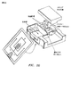
また別の実施形態では、流体スイッチが利用され得る。好ましくは、空気ベース流体スイッチが利用され得る。別の実施形態では、セルソーターのためのマイクロ流体チップ設計は空気圧力変調を使用する。フロースイッチングまたはセルソーティングのための単一のサイドチャンネルがマイクロ流体デバイス中で使用され得る。説明のチャンネル幾何学は、マイクロ流体デバイス中に効率的空気フロースイッチングを提供する。また別のアスペクトでは、単一のサイドチャンネル上への二つのスイッチングバルブの連結は、空気スイッチング応答時間を最小にする。また別のアスペクトでは、カートリッジホルダーがマイクロ流体チップの空気制御のために提供される。 In another embodiment, a fluid switch may be utilized. Preferably, an air-based fluid switch can be utilized. In another embodiment, the microfluidic chip design for the cell sorter uses air pressure modulation. A single side channel for flow switching or cell sorting can be used in a microfluidic device. The described channel geometry provides efficient air flow switching in microfluidic devices. In yet another aspect, the coupling of two switching valves on a single side channel minimizes air switching response time. In yet another aspect, a cartridge holder is provided for air control of the microfluidic chip.
流体スイッチングシステムへの特定用途では、流体ソータースイッチングシステムは、流体媒体を受け取るのに適した入口と、前記入口に流体的に連結された流体チャンネルと、前記流体チャンネルに流体的に連結された第一および第二の側方フローチャンネルと、前記第一および第二の側方フローチャンネルに連結された第一および第二の空気圧バルブと、前記流体チャンネルに流体的に連結された第一および第二の出力であり、前記側方フローチャンネルの下流に配置されている出力と、制御システムであり、前記第一および第二のバルブに連結され、前記第一および第二の空気圧バルブを動作させる時間制御信号を提供する制御システムとを備えており、前記第二のバルブが開かれる前に前記第一のバルブが開かれることを特徴とする。また別のアスペクトでは、第二のバルブが開かれたのち第二のバルブが閉じる前に第一のバルブが閉じられることを特徴とする。また別のアスペクトでは、第二の側方フローチャンネルおよび第二の空気圧バルブが除去され、一つまたは二つの空気バルブを備えた単一の側方チャンネルを使用してソーティングを達成し得る。 In a particular application to a fluid switching system, a fluid sorter switching system includes an inlet suitable for receiving a fluid medium, a fluid channel fluidly coupled to the inlet, and a first fluidly coupled to the fluid channel. First and second lateral flow channels; first and second pneumatic valves coupled to the first and second lateral flow channels; and first and second fluidly coupled to the fluid channel. A second output, an output disposed downstream of the side flow channel, and a control system, coupled to the first and second valves, to operate the first and second pneumatic valves And a control system for providing a time control signal, wherein the first valve is opened before the second valve is opened.In another aspect, the first valve is closed after the second valve is opened and before the second valve is closed. In yet another aspect, the second side flow channel and the second pneumatic valve can be removed and sorting can be accomplished using a single side channel with one or two air valves.
また別の実施形態では、マイクロ流体セルソーターは光学スイッチと空気圧力変調の両方を使用する。光学的および光機械的設計も提供される。好ましくは二つのレーザー照明モジュールおよび暗照明モジュールが利用される。蛍光を集めるために好ましくは高機能高NA(開口数)対物レンズが使用される。 In yet another embodiment, the microfluidic cell sorter uses both optical switches and air pressure modulation. Optical and optomechanical designs are also provided. Preferably two laser illumination modules and a dark illumination module are used. A high function, high NA (numerical aperture) objective lens is preferably used to collect fluorescence.
発明のまた別のアスペクトでは、蛍光信号検出および処理システムおよび方法が利用される。アナログ信号をデジタル信号に変換するために好ましくはADCが使用される。一実施形態では、デジタル信号処理アルゴリズムがFPGAで実施される。 In yet another aspect of the invention, fluorescent signal detection and processing systems and methods are utilized. An ADC is preferably used to convert the analog signal to a digital signal. In one embodiment, the digital signal processing algorithm is implemented in an FPGA.
追加的に、カートリッジの自動アライメントが提供される。この発明は、システムに装填するカートリッジについての自動アライメント問題を解決する。 Additionally, automatic alignment of the cartridge is provided. The present invention solves the automatic alignment problem for cartridges loaded into the system.
また別のアスペクトでは、発明はマイクロ流体ソーター機器のアプリケーションソフトウェア設計に関する。外部装置からの生データを多重実行可能アプリケーションおよびプロセス間で記録可能無損失高速(秒あたり10メガビット以上)であるフォーマットでストリーミングする。 In yet another aspect, the invention relates to application software design for microfluidic sorter devices. Stream raw data from external devices in a format that is recordable, lossless and fast (10 megabits per second or more) between multiple executable applications and processes.
また別の実施形態では、マイクロ流体カートリッジプライミングステーションが提供される。発明は、マイクロ流体デバイスのプライミングのためのプライミングステーションを説明する。 In yet another embodiment, a microfluidic cartridge priming station is provided. The invention describes a priming station for priming microfluidic devices.
また別のアスペクトでは、セル(たとえば胎児のセル)の成長モニタリングおよび選択のためのダイリューションクローニングが提供される。発明は、そのようなセルの成長モニタリングおよび選択のためのダイリューションクローニング方法を説明する。 In yet another aspect, dilution cloning is provided for growth monitoring and selection of cells (eg, fetal cells). The invention describes a dilution cloning method for growth monitoring and selection of such cells.
発明の詳細な説明
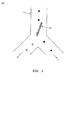
図1は、1×2マイクロ流体チャンネルネットワークすなわち一つのメイン入力チャンネル11と分岐ジャンクションから延びている二つの出力チャンネル12と13とを備えたネットワーク中のセルをソートする役目をする光学スイッチ10の一実施形態を示す。分岐ジャンクションのための「Y」幾何学が図1に示されるが、「T」幾何学などの他の分岐も使用され得る。一般に、これらのマイクロ流体チャンネルは、チャンネル中への光学スイッチおよび他のセル検出光学の投射を可能にするために、光学的透明基板中に作製される。この基板は、これに限定されないが、一般にガラス、石英、プラスチックたとえばポリメチルメタクリレート(PMMA)ほか、および成型可能または加工可能なポリマー(たとえばポリジメチルシロキサン、PDMSまたはSU8)である。マイクロ流体チャンネルの深さは、これに限定されないが、一般に10μmないし100μm範囲内にある。マイクロ流体チャンネルの幅は、これに限定されないが、一般に深さの1ないし5倍である。断面は一般に長方形か、チャンネルの等方性エッチングが後続するガラス基板のフォトリソグラフィックマスキングによって作製されるマイクロ流体チャンネルの場合には四半円形角を備えた長方形である。
DETAILED DESCRIPTION OF THE INVENTION FIG. 1 serves to sort cells in a 1 × 2 microfluidic channel network, ie a network with one
フロー条件は、ビームがジャンクション領域にあたらないように(この場合レーザーからの)光学ビームがオフにされるか遮断されると、すべてのセルが出力チャンネルの一つ、たとえば右の出力チャンネル13へ優先的に流れるように設定される。光学ビームがオンにされるか遮断解除されると、ビームがジャンクション領域に当たり、光学ビームとのセルの相互作用によって生成された光学的力がセルを左の出力チャンネル12へ方向付ける。この例では、セルの方向付けのために選ばれた光学パターンは、流体フローの方向に対してある角度をもつレーザー照明の長く細い線である。光学的グラディエント力はセルを、セルのメインストリーム線から側方へ遠ざけて変位させ、切り替えられたセルがそれから一つの出力チャンネルたとえば12へメインチャンネルを出るいっぽう、セルのメインストリームからの切り替えられていないセルが他の出力チャンネルたとえば13へ出る。マイクロ流体チャンネルネットワーク中のフロー条件の設定と制御は、直接駆動ポンピング、空気ポンピング、電気動力学、毛細管作用、重力または流体フローを生成する他の手段によって達成することができる。
The flow condition is that all cells go to one of the output channels, eg
スループット(分岐ジャンクションの上部においてソーティング領域に入るセルの時間的な割合)に関するソーティング機構の性能、産出効率(ターゲット出力チャンネル12中のターゲットセルのフラクション)、および純度(ターゲット出力チャンネル12中のセルの総数に対するターゲットセルの数の比)は、さまざまな要因によって影響を受け、それらのおのおのは光学スイッチの実施に影響する。光学スイッチは、マイクロ流体チャンネルネットワークのソーティングジャンクション領域内に投射される光学パターンの形状、分岐ジャンクションに対するパターンの位置、その初期位置および形状に対する光パターンの任意の運動、光学スイッチの動作の期間、光学スイッチパターンを生成するために使用されるレーザー源の波長とパワー、その他などのいくつかのパラメーターによって特徴づけることができる。光学スイッチに対するこれらのパラメーターの特定の値の選択は、数ある中でも、マイクロ流体チャンネルシステムのトポロジーと幾何学、マイクロチャンネルシステム内のフローレート(セル速度)、メインチャンネル中を流れるセルの位置(メインチャンネルの中央を流れるか片側へのオフセットを流れるか)を制御する能力、信頼できるスイッチングを達成するために必要なセルの変位の量、チャンネルの深さ、チャンネルの形状、および光スイッチとのセルの相互作用によって生成される力の臨界関数である。 Sorting mechanism performance in terms of throughput (time fraction of cells entering the sorting region at the top of the branch junction), output efficiency (fraction of target cells in target output channel 12), and purity (cells in target output channel 12) The ratio of the number of target cells to the total number) is affected by various factors, each of which affects the implementation of the optical switch. The optical switch is the shape of the optical pattern projected into the sorting junction area of the microfluidic channel network, the position of the pattern with respect to the branch junction, any movement of the optical pattern with respect to its initial position and shape, the duration of operation of the optical switch, the optical It can be characterized by several parameters, such as the wavelength and power of the laser source used to generate the switch pattern. The choice of specific values for these parameters for the optical switch includes, among other things, the topology and geometry of the microfluidic channel system, the flow rate (cell velocity) within the microchannel system, the position of the cell flowing through the main channel (main The ability to control whether the channel flows in the middle or the offset to one side), the amount of cell displacement required to achieve reliable switching, channel depth, channel shape, and cells with optical switch Is a critical function of the force generated by the interaction of.
一般に、セルがメインチャンネル中のフロー内へ導入されると、それらはフロー内の任意の側方位置においてチャンネルを下方に移動し得る。したがって、セルは、マイクロ流体チャンネル中の圧力駆動フローの周知の(円筒状マイクロ流体チャンネルに対して)放物線または(より一般的な断面に対して)疑似放物線の速度分布図によるそれらの側方位置に依存して、異なる速度で移動し得る。図1に示されるように、これは、一つの出力チャンネルたとえば13へすべてのセルのフローを偏らせるのを困難にするであろう。このフロー幾何学を備えた光学スイッチの任意の実施は必然的に、低いスループットと、光学スイッチを生成するために入手可能なレーザーパワーの非能率的な使用とに帰着するであろう。このフロー幾何学を備えた流体スイッチの任意の実施は、検出領域とスイッチング領域との間の変わりやすいセル飛行時間のために、低いスループット、純度および産出に帰着するであろう。適正フロー条件の使用は、光学または流体スイッチの性能に対するこれらの制限を緩和するのを支援することができる。 In general, as cells are introduced into the flow in the main channel, they can move down the channel at any lateral position in the flow. Thus, the cells are located at their lateral positions according to the well-known parabolic (relative to the cross-section) parabolic (relative to the cross-section) velocity distribution diagram of the pressure-driven flow in the microfluidic channel. Depending on the speed of movement. As shown in FIG. 1, this will make it difficult to bias the flow of all cells to one output channel, e.g. Any implementation of an optical switch with this flow geometry will necessarily result in low throughput and inefficient use of the laser power available to produce the optical switch. Any implementation of a fluid switch with this flow geometry will result in low throughput, purity and yield due to the variable cell flight time between the detection and switching regions. The use of proper flow conditions can help alleviate these limitations on optical or fluid switch performance.
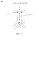
適正フロー条件の確立は多くの手法によって行なうことができる。一実施形態では、メインチャンネルの中央にある単一の縦列への(示された平面図中の水平への)セルの1次元集中は、図2に示されるようなシースフローアプローチを使用して、左21および右22の側の両方からのバッファーの追加フローでセル入力チャンネルフロー20をはさむことによって達成される。メインチャンネルの中央にセルを維持することは、各側からの等しいフローを有することによって達成される。図2に示されるように、このフローは流体分割平面23を効果的に作り出し、これは最終的に、分岐ジャンクションにおける流体およびセルの50/50分割に帰着する。このマイクロ流体チャンネル設計およびフロー条件を使用してセルの混成母集団からのターゲットセルをソートする光学スイッチの実施は、ターゲットセルを図1に示されるような一つの出力チャンネルたとえば12へ、非ターゲットセルを他の出力チャンネルたとえば13へ積極的に切り替える光学スイッチを必要とする。このマイクロ流体チャンネル設計およびフロー条件を使用してセルの混成母集団からのターゲットセルをソートする流体スイッチの実施は、ターゲットセルを図1に示されるような一つの出力チャンネルたとえば12へ、非ターゲットセルを他の出力チャンネルたとえば13へ積極的に切り替える流体スイッチを必要とする。図24の2チャンネル流体スイッチはそのような実施形態の例である。
Establishing proper flow conditions can be accomplished by a number of techniques. In one embodiment, one-dimensional concentration of cells (horizontally in the shown plan view) into a single column in the center of the main channel is performed using a sheath flow approach as shown in FIG. This is accomplished by sandwiching the cell
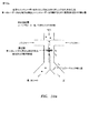
あるいは、セルの集中線は、サイドシースフローチャンネル内に不等なフローを置くことによってメインチャンネルの中央からオフセットして配置され得る、図3a〜b。これは、入力チャンネル30からメインチャンネル内の分割平面33の片側へのセルのスキューフローを効率的に引き起こす。セルフローが傾けられるメインチャンネルの側は、シースフローがより高いフローレートを有する側の反対側になる。すなわち、右のシースバッファー32が左のシースバッファー31よりも速く流れるとき、図3a〜bに示されるように、セルの線はメインチャンネルのフローの左の方へ傾けられる。しかしながら、左のシースフローはまた、メインチャンネルの右側の方へセルの線を押す、より高いフローを有することがある。図3a〜bにはまた、蛍光検出器34と光学スイッチ35が示される。蛍光検出器は、どのセルをソートするか決定する手段として使用され、後でさらに詳細に論じられる。効果的なソートは、負蛍光非ターゲットセルマイクロ流体チャンネル36へ分岐ジャンクションを出るフローストリームから正蛍光ターゲットセルマイクロ流体チャンネル37へ分岐ジャンクションを出るフローストリーム内へ分割平面を横切ってセルを移動させることを含んでいることが図3bから明白である。直接駆動ポンピング、空気ポンピング、電気動力学、毛細管作用、重力、または流体フローを生成する他の手段を使用してそれぞれの側のチャンネルのフローレートを別々に制御することによってか、マイクロ流体チャンネルのおのおの圧力低下を注意深く釣り合わせることを介して、中央フロー(50/50分割)またはオフセットフローが生じることを保証するようにマイクロ流体シースネットワークを特に設計することによってかのいずれかで達成することができる。
Alternatively, the cell concentration line may be placed offset from the center of the main channel by placing an unequal flow in the side sheath flow channel, FIGS. 3a-b. This effectively causes a cell skew flow from the
蛍光検出44の前にメインチャンネル中の入力フロー40から一つの出力マイクロ流体チャンネルたとえば蛍光負チャンネル46内へのすべてのセルの優先的フローを達成する代替アプローチは、等しいシースバッファーフローレート41と42を使用して中央ではさむことを得ることであるが、それから、蛍光正出力チャンネル47に対する蛍光負出力チャンネル46内への分岐ジャンクションからのより大きい容量の流体フローを有することにより、蛍光負チャンネル内へセルフローを優先的に偏らせる。これは図4a〜bに示され、左の出力チャンネル46が右の出力チャンネル47よりも広い。この構成は、分割平面43を中央配置セルストリームの右に効果的に置く。したがって、所望位置にあるセルに対して、光学または流体スイッチ45は、ターゲットセルを分割平面を横切ってターゲットセル・蛍光正・右出力チャンネル内へ移行するために使用される。このアプローチは、左の出力チャンネルよりも広い右の出力チャンネルを有することにより等しく有効であり、それによりターゲットセルは、光学または流体スイッチによって、中央配置セルストリームの左にいま配置されている分割平面を横切って移行され、したがって左の出力チャンネル内へソートされる。したがって、マイクロ流体チャンネル出口ネットワークを特に設計することによって、またはそれぞれの出口チャンネルの出口バック圧力を積極的に制御することによって、所望出力チャンネル内へのセルのフローを制御することができる。
An alternative approach to achieve preferential flow of all cells from the
中央フローまたはオフセットフローのいずれかの使用、および流体分割平面からの集中セルフローのそれぞれの距離は、信頼できるスイッチングを達成するために必要なセルの変位の大きさを最終的に要求する。これはさらに、信頼できる光学スイッチングを達成するために必要とされるレーザー線の長さとレーザーパワー、または信頼できる流体スイッチングを達成するために必要とされる空気パルスの振幅と持続時間を要求する。セルストリームが分割平面に近ければ近いほど、必要とされる変位は短く、ソーティング処理はより効率的になる。ソートされた母集団の向上された純度および高スループットのために、単方向配置中の光学または流体のいずれかの単一のスイッチは、標本ストリームが分割平面からオフセットされること必要とする。この手法では、誤ったソートの発生は最小にされる。セルとデブリが直径で1μmから50μmまで変化し得る最初の組織の単一のセル浮遊液などの大きさが種々雑多な標本に対して、スループットを犠牲にしてより大きいオフセットを奨励することは有利である。より均質の標本、たとえばセル線またはポリスチレンビーズに対しては、より小さいオフセットが増加したスループットを可能にするために選択され得る。 The use of either central flow or offset flow, and the respective distance of the concentrated cell flow from the fluid splitting plane, ultimately requires the amount of cell displacement necessary to achieve reliable switching. This further requires the laser line length and laser power required to achieve reliable optical switching, or the amplitude and duration of air pulses required to achieve reliable fluid switching. The closer the cell stream is to the splitting plane, the shorter the required displacement and the more efficient the sorting process. Because of the improved purity and high throughput of the sorted population, a single switch, either optical or fluid, in a unidirectional arrangement requires that the sample stream be offset from the splitting plane. With this approach, the occurrence of incorrect sorting is minimized. It is advantageous to encourage larger offsets at the expense of throughput for samples of various sizes, such as a single cell suspension of the initial tissue where cells and debris can vary in diameter from 1 μm to 50 μm It is. For more homogeneous specimens, such as cell lines or polystyrene beads, a smaller offset can be selected to allow increased throughput.
この設計の代替案は、二つのレーザー線を利用する双方向光学スイッチを使用することである。このアプローチでは、一方のレーザー線が所望のセルを一方の出力チャンネルへソートし、他方のレーザー線が他のすべてのセルを他方の出力チャンネル内へソートする。このアプローチは、50/50、図2、またはオフセット、図3と4、分割構成のいずれかと共に使用することができる。後者の場合、セルがスイッチングゾーンにないとき、一つがレーザーをその二つの位置状態のいずれかにしておくように選択し得る、または一つがまたこの時間のあいだレーザーを遮断し得る。光学スイッチはまた、分岐ジャンクションのちょうど上に配置されたスイッチング領域にあたる二つの鏡像レーザー線を有することにより双方向にすることができ、それらは独立につけられて分岐ジャンクションから生じる二つの出力のいずれかにセルを方向付ける。 An alternative to this design is to use a bidirectional optical switch that utilizes two laser lines. In this approach, one laser line sorts the desired cell into one output channel and the other laser line sorts all other cells into the other output channel. This approach can be used with either 50/50, FIG. 2, or offset, FIGS. 3 and 4, split configurations. In the latter case, when the cell is not in the switching zone, one can choose to keep the laser in either of its two position states, or one can also shut off the laser during this time. The optical switch can also be bi-directional by having two mirror image laser lines in the switching area located just above the branch junction, which are turned on independently and either of the two outputs resulting from the branch junction. Orient cells to.
1×2マイクロ流体ネットワーク中でレーザー線を使用する双方向光学スイッチの模型が図5に示される。図6に示されるように、同様の双方向光学スイッチがまた、チャンネルのいずれかの側に方向付けられたレーザースポットで達成された。単方向光学スイッチでのように、単一のレーザー源を双方向光学スイッチ中で使用することができ、または代替的に双方向光学スイッチが二つの独立したレーザー源を使用することができる。双方向設計は単方向設計に対していくつかの性能の利点を潜在的に提供する。第一は、すべてのセルがレーザーによって方向付けられるので、純度が潜在的に最大にされるということである。第二に、フローのいくつかの所定比率の代わりに、二つの出力ポートのおのおのに等しいフローを方向付けることができるので、流体フローが単純化される。 A model of a bi-directional optical switch using laser lines in a 1 × 2 microfluidic network is shown in FIG. As shown in FIG. 6, a similar bi-directional optical switch was also achieved with a laser spot directed to either side of the channel. As with a unidirectional optical switch, a single laser source can be used in the bidirectional optical switch, or alternatively, the bidirectional optical switch can use two independent laser sources. Bidirectional designs potentially offer several performance advantages over unidirectional designs. The first is that purity is potentially maximized because all cells are directed by a laser. Secondly, instead of some predetermined ratio of flows, the flow equal to each of the two output ports can be directed, thus simplifying the fluid flow.
この説明ではこれまで、一つの入力メインチャンネルを通って二つの出力チャンネルへの分岐内へのフローの1×2マイクロ流体チャンネル設計だけを考慮したが、1×NまたはM×N出力を備えたマイクロ流体ネットワークを利用することができる。任意な多数の独立変調レーザー線または独立側方フローチャンネルを有することにより、これらのより大きいネットワーク中で光学または流体スイッチングを達成することができる。いくつかの実施形態が図7a〜cで示される。さらに、ソートの純度を高めるために同一ソーターを介してセルを複数回フィードバックすることもでき、または代替的に、複数レベルのソーティングのためにチャンネルを縦つなぎに配置することもできる。 So far this discussion has considered only a 1 × 2 microfluidic channel design of flow into a branch through two input channels through one input main channel, but with 1 × N or M × N outputs. A microfluidic network can be used. By having any number of independently modulated laser lines or independent lateral flow channels, optical or fluid switching can be achieved in these larger networks. Some embodiments are shown in Figures 7a-c. In addition, cells can be fed back multiple times through the same sorter to increase the purity of the sort, or alternatively, the channels can be arranged in cascade for multiple levels of sorting.
単方向または双方向配置で光学スイッチを運転するとき、二つの異なる動作モードを考慮することができる、
パッシブモードまたはアクティブモード。パッシブモードは、どんなセルがチャンネルを通って流れているかにかかわらず、光学スイッチの状態がオンまたはオフのいずれかをとるものである。この場合、いつまたはどれくらい多くのセルがスイッチング領域に入るかについての知識は必要とされず、したがって、レーザーの状態に依存して、スイッチング領域内のすべてのセルが切り替えられる。一方、アクティブモードでは、セルは、まず、検出/選択領域に入ると検出され、それから、ある決定処理に基づいて切り替えられる。図3a〜bと図4a〜bは、ちょうどスイッチング領域の直前に置かれた蛍光検出器を使用するこのモードの例を示す。この場合、すべての蛍光セルが一方の出力チャンネルへ方向付けられ、すべての非蛍光セルが他方の出力チャンネルへ方向付けられた。決定処理のための他の非蛍光検出/選択技術は、飛行時間、散乱、結像、キャパシタンス、または所望のセルを識別することができる任意の検出様式を含んでいる。検出/選択方法にかかわらず、アクティブモードを使用するスイッチングは、ある決定処理に基づいてセルの一つの母集団を他からソートするために利用することができる。
When operating the optical switch in a unidirectional or bidirectional arrangement, two different operating modes can be considered,
Passive mode or active mode. Passive mode is one in which the state of the optical switch is either on or off, regardless of what cell is flowing through the channel. In this case, knowledge of when or how many cells enter the switching region is not required, and therefore all cells in the switching region are switched depending on the state of the laser. On the other hand, in the active mode, a cell is first detected when entering the detection / selection area, and then switched based on some decision process. Figures 3a-b and 4a-b show an example of this mode using a fluorescence detector placed just before the switching region. In this case, all fluorescent cells were directed to one output channel and all non-fluorescent cells were directed to the other output channel. Other non-fluorescent detection / selection techniques for the decision process include time of flight, scatter, imaging, capacitance, or any detection modality that can identify the desired cell. Regardless of the detection / selection method, switching using active mode can be used to sort one population of cells from another based on a decision process.
アクティブモードを利用するために、光学ビームは、決定処理に応じてオンまたはオフに変調されなければならない。使用するレーザーの数、または光学スイッチが単方向または双方向のどちらであるかにかかわらず、レーザーは、電気光学変調器を使用すること、レーザーパワーを変調すること、レーザーを遮断すること、液晶変調器を使用すること、ガルバノメーターを使用すること、音響光学変調器を使用することを含め、多くの手法によって変調することができる。二つのレーザーを備えた双方向光学スイッチについては、別々のレーザーは独立にオンおよびオフすることができる。しかしながら、単一のレーザー源を使用するとき、光学スイッチ線の二つの異なる配向は、(液晶変調器などの)偏光回転子を使用して、二つの異なる線パターンのおのおのを二つの別々の偏光のおのおのにすることによって達成することができる。同様に、使用する単一のスポットの位置を変調するために光学スイッチとして音響光学変調器またはガルバノミラーを使用することができ、また、使用する二つの異なる線形状を引くために双方向光学スイッチとして二軸音響光学変調器または二軸ガルバノミラーを使用することができる。 In order to utilize the active mode, the optical beam must be modulated on or off depending on the decision process. Regardless of the number of lasers used or whether the optical switch is unidirectional or bidirectional, the laser can use an electro-optic modulator, modulate the laser power, shut off the laser, liquid crystal Modulation can be done by a number of techniques, including using a modulator, using a galvanometer, and using an acousto-optic modulator. For a bidirectional optical switch with two lasers, the separate lasers can be turned on and off independently. However, when using a single laser source, two different orientations of the optical switch line can be obtained by using a polarization rotator (such as a liquid crystal modulator) to separate each of the two different line patterns into two separate polarizations. This can be achieved by making each one. Similarly, an acousto-optic modulator or galvanometer mirror can be used as an optical switch to modulate the position of a single spot used, and a bi-directional optical switch to draw two different line shapes to use A biaxial acousto-optic modulator or a biaxial galvanometer mirror can be used.
図8は、光学スイッチの変調および/または遮断を実施するための三つの異なる可能な光学設計を示す。図8aでは、液晶変調器(LCM)に向けて方向づけられ通過する単一の光学ビーム(レーザー)から双方向光学スイッチが作り出される。LCMは偏光回転子であり、したがって、ビームが一方向に偏光されると、それは直進し、偏光ビームスプリッター(PBS)を通り、線形状を作り出すシリンドリカルレンズを通り、別のPBSを通り、それから線をマイクロ流体スイッチング領域に集光するいくつかの集光光学部品を通る。これは、分岐チャンネル出力の一方内へセルを切り替えるために使用される双方向光学スイッチの一方の線を効果的に作り出す。他方の出力チャンネル内へセルを切り替えるため、鏡像線が作り出されなければならない。これはビームの偏光を変更するLCMを回転させることにより遂行される。したがって、ビームが最初のPBSに当たると、それは代替パスに方向付けられ、(線形状を作り出す)異なるシリンドリカルレンズを通り、他方のPBSを通り、それはビームを方向づけ、鏡像線をマイクロ流体スイッチング領域上に集光する集光光学部品を通る。双方向光学スイッチのための線形状を作り出すためにシリンドリカルレンズを使用したが、
代替的に、シリンドリカルレンズを除去して光学スイッチのために使用されるスポットとすることができることに注意されたし。図8bでは、LCMとPBSの組み合わせを使用するのではなく、シリンドリカルレンズありまたはなしで、双方向光学スイッチに使用される線またはスポットを作り出すために音響光学変調器(AOM)を使用することができる。これは、必要とされる所望の線形状を得るためにAOMを構成することによって達成される。また、オン/オフ様式で光学ビームを遮断するためにAOMを使用して、光学スイッチオフ状態のためのビームストップへビームを方向付けることができる。図8cは、図8aと図8bに説明したシステムの組み合わせを示す。AOMを使用してビームの方向を変更する任意の構成では、所望のビーム運動に依存して一軸または二軸のいずれかのガルバノミラーがAOMの代わりに使用され得る。
FIG. 8 shows three different possible optical designs for implementing modulation and / or blocking of the optical switch. In FIG. 8a, a bi-directional optical switch is created from a single optical beam (laser) directed and passed towards a liquid crystal modulator (LCM). An LCM is a polarization rotator, so when a beam is polarized in one direction, it goes straight, passes through a polarizing beam splitter (PBS), passes through a cylindrical lens that creates a line shape, passes through another PBS, and then a line. Through several collection optics that collect the light into the microfluidic switching region. This effectively creates one line of a bidirectional optical switch that is used to switch the cell into one of the branch channel outputs. In order to switch the cell into the other output channel, a mirror image line must be created. This is accomplished by rotating the LCM that changes the polarization of the beam. Thus, when the beam hits the first PBS, it is directed to an alternative path, passing through a different cylindrical lens (creating a line shape) and passing through the other PBS, which directs the beam and places the mirror line on the microfluidic switching region It passes through a condensing optical component that collects light. A cylindrical lens was used to create the line shape for the bidirectional optical switch,
Note that alternatively, the cylindrical lens can be removed to be the spot used for the optical switch. In FIG. 8b, rather than using a combination of LCM and PBS, an acousto-optic modulator (AOM) may be used to create a line or spot used for a bi-directional optical switch with or without a cylindrical lens. it can. This is accomplished by configuring the AOM to obtain the desired line shape that is required. Also, an AOM can be used to block the optical beam in an on / off manner, and the beam can be directed to a beam stop for an optical switch off condition. FIG. 8c shows a combination of the systems described in FIGS. 8a and 8b. In any configuration that uses AOM to change the direction of the beam, either uniaxial or biaxial galvanometer mirrors can be used in place of AOM, depending on the desired beam motion.
単または双方向光学スイッチについてのスイッチング効率を最適化するとき光学パターンのための多くの変形を考慮することができる。上述したように、レーザー線は光学スイッチパターンとして使用した。線は、シリンドリカルレンズによって、ガルバノミラーまたは音響光学変調器を走査することによって、回折光学部品によって、カスタム屈折光学部品によって、または任意の他の技術によって生成され得る。これまで、線は、シリンドリカルレンズによって、ガルバノミラーを走査することによって、または音響光学変調器を使用することによって生成された。線の長さは任意に長く、または単一の点と同じくらい短くすることができる。線は、線の頂上においてより高い強度を有し、線の端に向けて強度が徐々に減少するようにすることができる。付加的に、線は、セルの出力方向を最適化する曲がった弓形であってもよい。付加的に、リアルタイムで、線の角度または線の形状が変化してもよい(すなわち出力を最適化するスイベル)。複数の出力チャンネルを備えた実施については、各出力セルの方向を最適化するために2D空間のあらゆる任意のパターンの線が生成されてもよい。あるいは、線は、離散スポットのアレイによって作り出されてもよい。 Many variations for the optical pattern can be considered when optimizing the switching efficiency for a single or bidirectional optical switch. As described above, the laser line was used as an optical switch pattern. The line may be generated by a cylindrical lens, by scanning a galvanometer mirror or acousto-optic modulator, by diffractive optics, by custom refractive optics, or by any other technique. So far, the lines have been generated by scanning a galvanomirror with a cylindrical lens or by using an acousto-optic modulator. The length of the line can be arbitrarily long or as short as a single point. The line may have a higher intensity at the top of the line, with the intensity gradually decreasing towards the end of the line. Additionally, the line may be a curved bow that optimizes the output direction of the cell. Additionally, the line angle or line shape may change in real time (ie, a swivel that optimizes output). For implementations with multiple output channels, any arbitrary pattern of lines in 2D space may be generated to optimize the direction of each output cell. Alternatively, the line may be created by an array of discrete spots.
スループット、産出効率および純度の点からソーティング機構の性能をさらに改善するために、光学スイッチは、選択セルが分岐ジャンクションに向かってメインチャンネルを下方へ流れるとき、レーザースポットがそれの横側に掃引され、それによりセルとレーザーの間の総相互作用時間を増大するように構成された。光学スイッチは、分岐ジャンクションに向かってメインチャンネルの長さを下方へ直線的に移行されるレーザースポットを利用する。スポットによって掃引された線は、メインチャンネル(図9a)の壁と平行とすることができ、またはセルフローストリーム(図9b)に対して角度をもたせることができる。したがって、角度は0〜90度に及ぶことができる。スポットを掃引する能力はAOMまたは走査ガルバノミラーのいずれかを使用して達成される。光学スイッチは、所望のセルを識別することができる蛍光または他の検出様式、たとえば飛行時間、散乱、結像またはキャパシタンス、を使用する所望のセルの検出に基づいた決定によって掃引するように作動される。セル位置は、メインチャンネル中でオフセットまたは中央配置することができ、それは、効率的なスイッチング/ソーティングを達成するために使用される、スポットによって掃引される線の長さおよびレーザーパワーを要求する。したがって、所望のセルが検知されると光学スイッチがオンにされ、スポットが所望のセルの横側に現われる。それから、スポットは選択セルの横側に追跡し、光学的力を使用して選択セルを所望の出力チャンネル内へ方向付ける。 To further improve the performance of the sorting mechanism in terms of throughput, yield efficiency and purity, the optical switch allows the laser spot to be swept to the side of it when the selected cell flows down the main channel towards the branch junction. , Thereby increasing the total interaction time between the cell and the laser. The optical switch utilizes a laser spot that is linearly shifted down the length of the main channel toward the branch junction. The line swept by the spot can be parallel to the wall of the main channel (FIG. 9a) or can be angled with respect to the cell flow stream (FIG. 9b). Thus, the angle can range from 0 to 90 degrees. The ability to sweep the spot is achieved using either an AOM or a scanning galvanometer mirror. The optical switch is actuated to sweep by a determination based on detection of the desired cell using fluorescence or other detection modalities that can identify the desired cell, e.g. time of flight, scattering, imaging or capacitance. The The cell location can be offset or centered in the main channel, which requires the length of the line swept by the spot and the laser power used to achieve efficient switching / sorting. Thus, when a desired cell is detected, the optical switch is turned on and a spot appears beside the desired cell. The spot is then tracked to the side of the selected cell and optical force is used to direct the selected cell into the desired output channel.
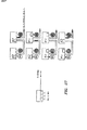
光学または流体スイッチの効率的なトリガリングを容易にする二つのアプローチを以下に述べる。両方の方法に典型的なのは、動いているセルを分析する一時的な信号の使用であり、切り替えるか切り替えないかの決定を生成するためにこの情報を使用する。この一時的な信号は本質的に時間の関数としての信号の測定であり、それはピーク強度とピーク幅の両方の点から特殊な一時的な指紋を産出することができる。信号は蛍光、散乱(たとえば前方散乱)、キャパシタンス、結像、または所望のセルを識別することができる任意の検出様式であってよい。一つのアプローチは、セル検出とセル識別の両方を遂行するために二つ以上の検出器に結合された単一のレーザー源を利用することである。図10a〜dは、蛍光検出器と前方散乱検出器を組み合わせた一つのレーザー源を使用するこのアプローチを示す。これらの検出器からの一時的な信号は切り替え決定の情報として使用される。セルの存在は、前方散乱信号と、この信号が所定の範囲内にある蛍光信号強度といつ結合されるかによって確認され、それから、この「ゲーティング」情報が光学スイッチを作動させるために使用される。単一の蛍光検出器だけが示されるが、さらに洗練されたセル識別のために複数の蛍光検出器を使用することができることに注意されたし。その場合、等しいフローレートシースバッファーを使用することによって、セルストリームは中央に配置され、出力チャンネルは、セルストリームの右に分割平面を作り出すために使用される異なる幅を有する。しかしながら、上述したようにセルストリームおよび分割平面の位置を操作ために使用される任意の構成を使用することができる。また、両方の構成に共通のことは、エラーチェック検出器の存在であり、それはセルが切り替えられたか否かを確認する。この場合の検出は、蛍光、散乱(たとえば前方散乱)、キャパシタンス、結像、または所望のセルを識別することができる任意の検出様式に基づくことができる。 Two approaches that facilitate efficient triggering of optical or fluidic switches are described below. Typical for both methods is the use of a temporary signal to analyze a moving cell and use this information to generate a decision to switch or not switch. This temporal signal is essentially a measurement of the signal as a function of time, which can yield a special temporal fingerprint in terms of both peak intensity and peak width. The signal may be fluorescence, scatter (eg, forward scatter), capacitance, imaging, or any detection modality that can identify the desired cell. One approach is to utilize a single laser source coupled to two or more detectors to perform both cell detection and cell identification. Figures 10a-d illustrate this approach using a single laser source that combines a fluorescence detector and a forward scatter detector. Temporary signals from these detectors are used as switching decision information. The presence of the cell is confirmed by the forward scatter signal and when this signal is combined with the fluorescence signal intensity within a predetermined range, and then this “gating” information is used to activate the optical switch. The Note that only a single fluorescence detector is shown, but multiple fluorescence detectors can be used for more sophisticated cell identification. In that case, by using an equal flow rate sheath buffer, the cell stream is centered and the output channel has a different width used to create a split plane to the right of the cell stream. However, any configuration used to manipulate cell stream and split plane positions as described above can be used. Also common to both configurations is the presence of an error check detector, which confirms whether a cell has been switched. Detection in this case can be based on fluorescence, scatter (eg, forward scatter), capacitance, imaging, or any detection modality that can identify the desired cell.
図10a〜bは、ソートパラメーターが負で光学または流体スイッチが作動されないときの検出器装置とタイミング/トリガー図を示す。セルは、メイン流体チャンネルに入り、両側から流れるシースバッファーによって単一の縦列に集中される。セルが検出/選択領域のレーザーを通過するとき、蛍光および前方散乱信号の両方が同時にまたはほとんど同時に検知される。(時刻t1の)前方散乱信号によってセルの存在が首尾よく検知されるが、蛍光信号はゲーティングレベル未満であり、光学スイッチは(時刻t2に)作動されない。したがって、セルが切り替えられなかったので、(時刻t3の)エラーチェック信号が得られない。一方、図10c〜dは、ソートパラメーターが正で光学または流体スイッチが作動されるときの検出器装置とタイミング/トリガー図を示す。ここで、セルが検出/選択領域のレーザーを通過するとき、蛍光および前方散乱信号の両方が同時にまたはほとんど同時に検知されるが、蛍光信号はゲーティングレベル内にあり、光学または流体スイッチは(時刻t2に)作動される。セルが切り替えられたので、(時刻t3の)エラーチェック信号が得られる。このアプローチでは、(時刻t2の)トリガー時刻は、初期検知時刻(t1)から測定されたプリセット値(Δt)であり、このΔt値は、セルの速度と、検出/選択領域に対する光学スイッチの位置とによって決定される。このアプローチは満足に、効率的なソーティングを達成するものであるが、
トリガリング精度をさらに改善する手段として第二のアプローチが使用される。
10a-b show the detector device and timing / trigger diagram when the sort parameter is negative and the optical or fluid switch is not activated. Cells enter the main fluid channel and are concentrated in a single column by sheath buffers flowing from both sides. As the cell passes through the detection / selection region laser, both fluorescence and forward scatter signals are detected simultaneously or nearly simultaneously. The presence of cells by forward scatter signal (at time t1) is detected successfully, the fluorescence signal is less than the gating level, optical switch is not actuated (in the time t 2). Therefore, since the cell has not been switched, (at time t 3) no error checking signal is obtained. On the other hand, FIGS. 10c-d show the detector device and timing / trigger diagram when the sort parameter is positive and the optical or fluid switch is activated. Here, as the cell passes through the detection / selection region laser, both fluorescence and forward scatter signals are detected simultaneously or nearly simultaneously, but the fluorescence signal is within the gating level and the optical or fluidic switch is (time to t 2) is activated. Since the cell has been switched, the error check signal is obtained (at time t 3). In this approach, the trigger time (at time t 2 ) is a preset value (Δt) measured from the initial detection time (t 1 ), which is the cell speed and optical switch for the detection / selection area. And the position of This approach achieves satisfactory and efficient sorting,
A second approach is used as a means to further improve triggering accuracy.
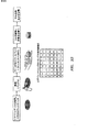
図11a〜dはこの第二のアプローチを示し、二つのレーザー源が一つの代わりに使用される。また、上述した単一のレーザーアプローチでのように、これらの検出器からの一時的な信号はスイッチ決定のための情報として使用される。識別/選択領域の前でセル検出を別に遂行するために、一つのレーザーが検出ゾーンの中で使用される。この場合の検出は、蛍光、散乱(たとえば前方散乱)、キャパシタンス、結像、または所望のセルを識別することができる任意の検出様式に基づくことができる。第二のレーザーは二つ以上の検出器と結合され、セル検出とセル識別を遂行するために使用される。再び、この場合の識別は、蛍光、散乱(たとえば前方散乱)、キャパシタンス、結像、または所望のセルを識別することができる任意の検出様式に基づくことができる。二つの連続するセル検出ステップの目的は、(時刻t1の)第一の検出と(時刻t2の)第二の検出の間の時間差(Δt)からセルフローレートを得ることができるようにするものである。検出器窓(d)間の間隔を知ることはフローレート(v=d/t))を与え、識別窓(x)から光学または流体スイッチがある既知の値と組み合わされたこの値は次に光学スイッチ(t3=x/v)のためのトリガリング時刻を計算するために使用される。特定のゲーティングレベルがセル識別ステップの間に到達されるときにだけ、再び切り替えが起こる。識別のために単一の蛍光検出器だけが示されるが、複数の蛍光検出器を使用することができる。描写の場合では、等しいフローレートシースバッファーを使用することによってセルストリームは中央に配置され、セルストリームの右に分割平面を作り出すために出力チャンネルは異なる幅を有する。しかしながら、上述したようにセルストリームおよび分割平面の位置を操作ために使用される任意の構成を使用することができる。また、両方の構成に共通のことは、エラーチェック検出器の存在であり、それはセルが切り替えられたか否かを確認する。この場合の検出は、蛍光、散乱(たとえば前方散乱)、キャパシタンス、結像、または所望のセルを識別することができる任意の検出様式に基づくことができる。 Figures 11a-d show this second approach, where two laser sources are used instead of one. Also, as in the single laser approach described above, the temporal signals from these detectors are used as information for switch determination. One laser is used in the detection zone to perform cell detection separately in front of the identification / selection area. Detection in this case can be based on fluorescence, scatter (eg, forward scatter), capacitance, imaging, or any detection modality that can identify the desired cell. The second laser is combined with two or more detectors and is used to perform cell detection and cell identification. Again, the identification in this case can be based on fluorescence, scatter (eg, forward scatter), capacitance, imaging, or any detection modality that can identify the desired cell. The purpose of the two successive cell detection steps is to be able to obtain the cell flow rate from the time difference (Δt) between the first detection (at time t 1 ) and the second detection (at time t 2 ). To do. Knowing the spacing between detector windows (d) gives the flow rate (v = d / t)), and this value combined with a known value from the identification window (x) with an optical or fluid switch is then Used to calculate the triggering time for the optical switch (t 3 = x / v). Switching occurs again only when a specific gating level is reached during the cell identification step. Only a single fluorescence detector is shown for identification, but multiple fluorescence detectors can be used. In the depicted case, the cell stream is centered by using equal flow rate sheath buffers and the output channels have different widths to create a split plane to the right of the cell stream. However, any configuration used to manipulate cell stream and split plane positions as described above can be used. Also common to both configurations is the presence of an error check detector, which confirms whether a cell has been switched. Detection in this case can be based on fluorescence, scatter (eg, forward scatter), capacitance, imaging, or any detection modality that can identify the desired cell.
図11a〜bは、ソートパラメーターが負で光学または流体スイッチが作動されないときの検出器装置とタイミング/トリガー図を示す。セルは、メイン流体チャンネルに入り、両側から流れるシースバッファーによって単一の縦列に集中される。セルが検出窓領域を通過するとき、(時刻t1の)前方散乱信号によってその存在が確認される。セルが識別/選択窓を通過するとき、(時刻t2に)第二の前方散乱信号が得られるが、この信号は、ゲーティングレベル内にない(時刻t2の)蛍光信号強度と結合され、光学または流体スイッチは(時刻t3に)作動されない。セルが切り替えられなかったので、(時刻t4の)エラーチェック信号は得られない。セルをソートすることすらせずに、(t1),(t2)と、検出および識別窓間の既知の距離(d)を使用してセルストリームのフローレート(v)が得られる。これは、Δt=(t2)−(t1)およびv=d/Δtの関係を使用して得られる:。 FIGS. 11a-b show the detector device and timing / trigger diagram when the sort parameter is negative and the optical or fluid switch is not activated. Cells enter the main fluid channel and are concentrated in a single column by sheath buffers flowing from both sides. As the cell passes through the detection window region, its presence is confirmed by the forward scatter signal (at time t1). When a cell passes through the identification / selection window, (at time t 2) it is the second forward scatter signal is obtained, this signal is coupled not to the gating level inside (at time t 2) fluorescence signal intensity , optical or fluidic switch is not activated (at time t 3). Since the cell has not been switched, (time t 4) error check signal can not be obtained. Without sorting the cells, the flow rate (v) of the cell stream is obtained using (t 1 ), (t 2 ) and the known distance (d) between the detection and identification windows. This is obtained using the relationship Δt = (t 2 ) − (t 1 ) and v = d / Δt:
一方、図11c〜dは、ソートパラメーターが正で光学または流体スイッチが作動されるときの検出器装置とタイミング/トリガー図を示す。ここで、セルが検出窓領域を通過するとき、(時刻t1の)前方散乱信号によってその存在が再び確認される。セルが識別/選択窓を通過するとき、(時刻t2に)第二の前方散乱信号が得られ、この信号は、ゲーティングレベル内にある(時刻t2の)蛍光信号強度と結合され、光学または流体スイッチが(時刻t3に)作動される。セルが切り替えられたので、(時刻t4の)エラーチェック信号がいま得られる。このアプローチでは、トリガー時刻(t3)はプリセット値ではなく、セルストリームフローレート(v)と、光学スイッチと識別ウィンドウの間の既知の距離(x)とを使用して計算される。これは、Δt=(t2)―(t1)、v=d/Δt、(t3)=x/vの関係を使用して得られる。このアプローチは、セルフローレートの変動を明らかにし、それにより、より正確に光学または流体スイッチを作動させることができるより効率的なソーティングを与える。光学スイッチングのためのこのアプローチの付加利益は、個々のセルについて、上述したように決定されるセルの速度と一致するようにレーザースポットがチャンネルを下方に移行されるレートを調節し、したがってセルと光学スイッチのレーザースポットとの間の相互作用時間の最大にすることの可能性である。レーザースポットの移行速度は、AOMのためのドライバーを変えることによって変えられる。 On the other hand, FIGS. 11c-d show the detector device and timing / trigger diagram when the sort parameter is positive and the optical or fluid switch is activated. Here, when the cell passes through the detection window region, its presence is again confirmed by the forward scatter signal (at time t1). When a cell passes through the identification / selection window (time to t 2) the second forward scatter signal is obtained, this signal is in the gating level inside (at time t 2) is coupled with fluorescence signal intensity, optical or fluidic switch is (at time t 3) is activated. Since the cell is switched, obtained (time t 4) error check signal is now. In this approach, the trigger time (t 3 ) is calculated using the cell stream flow rate (v) and the known distance (x) between the optical switch and the identification window, rather than a preset value. This is obtained using the relationship Δt = (t 2 ) − (t 1 ), v = d / Δt, (t 3 ) = x / v. This approach accounts for cell flow rate fluctuations, thereby providing more efficient sorting where the optical or fluidic switch can be operated more accurately. The added benefit of this approach for optical switching is that for each individual cell, the rate at which the laser spot is moved down the channel is adjusted to match the cell speed determined as described above, and thus The possibility of maximizing the interaction time between the laser spot of the optical switch. The laser spot transition speed can be changed by changing the driver for the AOM.
上述したトリガリングアプローチを包含するが、ソーティング効率を改善する別のアプローチは、正確な標本コアを作り出すチャンネル設計を使用してセルをメインチャンネルの中央に配置することであり、それにより、コアはシースバッファーによって完全に取り囲まれる。チャンネル高さに沿ったセルの位置の変化性は、セル検出および蛍光強度の変化性を引き起こすことがある。メインチャンネルの中央を流れるコア中にセルがあることを確実にすることは、セルの放射状分布のためにあらゆる変化性を最小にし、効率的ソーティングを達成するために移動されるためにセルが必要とする距離を制御するので、ソーティング効率を改善し得る。そのようなコアフローは、シースバッファーでの入力フローストリームの2次元のピンチで達成することができる。 Another approach that improves the sorting efficiency, including the triggering approach described above, is to place the cell in the center of the main channel using a channel design that produces an accurate sample core, so that the core It is completely surrounded by a sheath buffer. Cell position variability along the channel height can cause cell detection and fluorescence intensity variability. Ensuring that the cells are in the core flowing through the center of the main channel minimizes any variability due to the radial distribution of the cells and requires the cells to be moved to achieve efficient sorting Therefore, the sorting efficiency can be improved. Such core flow can be achieved with a two-dimensional pinch of the input flow stream in the sheath buffer.
このアプローチは底部基板と上部基板を必要とし、
それらはそれぞれそれらの中に形成されたマイクロ流体チャンネルネットワークを備えている。図12a〜bと図13は、これを遂行する一つの方法を示し、一方の基板上のチャンネル設計は他方の基板上の設計の鏡像である。したがって、二つの基板がチャンネル設計を対向させて接合されると、チャンネルネットワークは完成した流体の流路を覆い形成する。図12a〜bは、このアプローチで使用される設計の一種を示し、標本チャンネルは破線として示される。このアプローチの重要な特徴は、標本チャンネルがシースチャンネルよりも浅く、その結果、基板が接合されたときに、標本流路が穴としてジャンクションに入るように見えることを確実にすることである。これは図13に示され、セルがジャンクションに入るのを見ることができ、次に、すべての側からはさまれて、メインチャンネルの中央に流れる標本コアを作り出す。チャンネルは、ガラスまたは石英のウェット化学エッチまたはレーザーエッチによって、またはプラスチックまたはポリマーに成型または浮き彫りすることによって形成することができることに注意されたし。
This approach requires a bottom substrate and a top substrate,
They each have a microfluidic channel network formed in them. FIGS. 12a-b and FIG. 13 show one way to accomplish this, where the channel design on one substrate is a mirror image of the design on the other substrate. Thus, when the two substrates are joined with the channel design facing each other, the channel network covers the completed fluid flow path. Figures 12a-b show one type of design used in this approach, with the sample channel shown as a dashed line. An important feature of this approach is to ensure that the sample channel is shallower than the sheath channel so that when the substrates are joined, the sample channel appears to enter the junction as a hole. This is shown in FIG. 13, where you can see the cell entering the junction, then creating a specimen core that is sandwiched from all sides and flows into the center of the main channel. Note that the channel can be formed by wet chemical or laser etch of glass or quartz, or by molding or embossing into plastic or polymer.
別の方法は、一連の交差チャンネルを、第一のジャンクション/交差においてセルがメインチャンネルの一つの壁に向けて垂直に押され、次のジャンクション/交差がこのセルストリームをメインチャンネルの中央に垂直に押しやり、それから第三のジャンクション/交差における両側からの最後のピンチフローが、メインチャンネルを流れる標本コアの周りに完成シースバッファー覆いを作り出すように配置することを含んでいる。これは図14と図15に示され、一つの可能なチャンネル模型が図16に示される。この例では、ジャンクション(A)において、標本は、上部基板からジャンクション内へ、底部基板中のチャンネル内へ下方へ流れ、そこではサイドシースバッファーがサイドからジャンクション内へ流れる。標本は、わずかに集中され、底部チャンネルの上壁に押し付けられ、次のジャンクション(B)に向かって流れ続ける。ジャンクション(B)において、標本は、ジャンクションAからジャンクション(B)へ、底部チャンネルの上部に沿って流れる。ここで、第二のシースバッファーが上部基板からジャンクション(B)内へ流れ込み、標本は底部基板中のチャンネルの真ん中まで押し下げられる。標本は、次のジャンクション(C)に向かって底部チャンネルの真ん中に沿って流れ続ける。ここで、第三のシースバッファーが両サイドからジャンクション(C)内に流れ込み、標本は単一の縦列へとはさまれる。標本はいまシースバッファーに取り囲まれ、メイン入力チャンネル内で水平と垂直の両方の中央に配置されて標本コアとして流れ続ける。 Another way is to push a series of cross channels vertically at the first junction / intersection, where the cells are pushed vertically towards one wall of the main channel, and the next junction / intersection perpendiculars this cell stream to the center of the main channel. And then the final pinch flow from both sides at the third junction / intersection is arranged to create a finished sheath buffer covering around the specimen core flowing through the main channel. This is shown in FIGS. 14 and 15, and one possible channel model is shown in FIG. In this example, at junction (A), the specimen flows from the top substrate into the junction and down into the channel in the bottom substrate where the side sheath buffer flows from the side into the junction. The specimen is slightly concentrated and pressed against the top wall of the bottom channel and continues to flow towards the next junction (B). At junction (B), the sample flows from junction A to junction (B) along the top of the bottom channel. Here, the second sheath buffer flows from the top substrate into junction (B) and the specimen is pushed down to the middle of the channel in the bottom substrate. The specimen continues to flow along the middle of the bottom channel towards the next junction (C). Here, the third sheath buffer flows into the junction (C) from both sides and the specimen is sandwiched in a single column. The specimen is now surrounded by a sheath buffer and is centered both horizontally and vertically within the main input channel and continues to flow as the specimen core.
別の方法は、1Dシースバッファーに直交の軸の浅いチャンネルを使用して放物線状速度分散の影響を最小にする。マイクロ流体チャンネル中の一次元フロー集中では、入口中央ストリーム中の粒子またはセルは一方向だけに沿ってはさまれる。はさみとフローの方向に垂直な方向に、放物線状速度特性が残る。チャンネルの中央に近い粒子は速く流れるが、チャンネル壁に近いものは遅く流れる。その結果、粒子またはセルは速度の分散を伴ってフローチャンネルを下方へ移動し、これは検出とスイッチング事象の同期を複雑にする。図34は、1Dマイクロ流体フロー集中の固有の問題を解決する方法を示すが、直交方向の粒子またはセルの大きさに匹敵するチャンネル深さを使用する。たとえば10マイクロメートルの直径の粒子またはセルでは、チャンネル深さは15マイクロメートルである。この場合、粒子またはセルは深さ方向にチャンネルの大部分を占め、その結果、それらは、速度分散を平均しチャンネルの速度分散を狭める速度を経験する。 Another method uses shallow channels with orthogonal axes in the 1D sheath buffer to minimize the effects of parabolic velocity dispersion. In a one-dimensional flow concentration in a microfluidic channel, particles or cells in the inlet central stream are sandwiched along only one direction. A parabolic velocity characteristic remains in the direction perpendicular to the direction of the scissors and flow. Particles near the center of the channel flow fast, but those near the channel wall flow slowly. As a result, the particles or cells move down the flow channel with velocity dispersion, which complicates detection and switching event synchronization. FIG. 34 shows how to solve the inherent problem of 1D microfluidic flow concentration, but using channel depths comparable to orthogonal particle or cell sizes. For example, for a 10 micrometer diameter particle or cell, the channel depth is 15 micrometers. In this case, the particles or cells occupy most of the channel in the depth direction, so that they experience a velocity that averages the velocity dispersion and narrows the velocity dispersion of the channel.
図1〜16に説明したすべてのマイクロ流体チャンネルネットワーク設計はガラス基板で、従来のフォトリソグラフィックマスキングと、マスクしたガラス基板の等方性エッチングとを利用して作製した。等方性エッチは一般に、チャンネルの中央に深さdeを、またチャンネルの上部に幅w=wp+2×deを有するマイクロ流体チャンネルを作り出す。ここで、wpはチャンネルを規定するフォトリソグラフィーの幅である。チャンネルの底部輪郭は、等方性エッチのために各角に四半円形輪郭を、またエッチされたチャンネルの上部に開口を有する。ガラス基板、一般にガラス蓋スリップが、エッチされたマイクロ流体チャンネルを備えた基板に熱的に接合されて、チャンネルの上部を密閉し、マイクロ流体チャンネルネットワークを完成させる。熱的接合の前に上部基板に穴が一般にドリルで空けられてマイクロ流体チャンネルネットワークへの流体フローの進入と退出のためのビアを提供するが、代わりに、上部基板にではなくエッチされた底部基板に穴がドリルで空けることもできる。チャンネルの深さdeは、化学エッチ工程のレートとエッチステップの期間に依存する。マイクロ流体チャンネルの深さは、これに限定されないが、一般に10μmないし100μm範囲内にある。マイクロ流体チャンネルの幅は、これに限定されないが、一般に深さの2〜5倍である。これは、これに限定されないが、一般に5μmないし400μm範囲内にあるフォトリソグラフィー上の線を使用することによって達成される。前述したように、プラスチックまたはモールド可能または成型可能なポリマーなど、他の基板が使用され得る。これらの場合、マイクロ流体チャンネルは一般に矩形断面を有するが、そのほかはガラス基板のチャンネルと同様である。マイクロ流体チャンネルネットワークが作製されるガラス基板の大きさは、これに限定されないが、一般に5mm×5mmないし25mm×50mmの範囲内にあり、総厚さは、これに限定されないが、500μmないし2mm範囲内にある。上部基板は一般に同じ大きさで、厚さは、これに限定されないが、300μmないし1mm範囲内にある。ビアは、これに限定されないが、直径が一般に200μmないし600μmである。マイクロ流体チャンネルネットワークと、流体フローの進入と退出のための流体ポートのためのビアを備えた接合カバープレートとを備えた完成基板は、マイクロ流体ソーティングチップまたは簡潔にチップと呼ばれる。 All the microfluidic channel network designs described in FIGS. 1-16 were made of glass substrates using conventional photolithographic masking and isotropic etching of the masked glass substrate. The isotropic etch Generally, the depth d e in the center of the channel, also produce microfluidic channels at the top of the channel has a width w = w p + 2 × d e. Here, w p is the width of photolithography that defines the channel. The bottom profile of the channel has a quarter circle profile at each corner for isotropic etching and an opening at the top of the etched channel. A glass substrate, typically a glass lid slip, is thermally bonded to a substrate with etched microfluidic channels to seal the top of the channels and complete the microfluidic channel network. Prior to thermal bonding, holes in the top substrate are typically drilled to provide vias for fluid flow in and out of the microfluidic channel network, but instead etched bottom instead of in the top substrate You can also drill holes in the board. The depth d e of the channel is dependent on the duration of the rate and etch step chemical etching process. The depth of the microfluidic channel is not limited to this, but is generally in the range of 10 μm to 100 μm. The width of the microfluidic channel is not limited to this, but is generally 2-5 times the depth. This is achieved by, but not limited to, using photolithographic lines that are generally in the 5 μm to 400 μm range. As previously mentioned, other substrates such as plastic or moldable or moldable polymers may be used. In these cases, the microfluidic channel generally has a rectangular cross section, but otherwise is similar to the channel of the glass substrate. The size of the glass substrate on which the microfluidic channel network is fabricated is not limited to this, but is generally in the range of 5 mm × 5 mm to 25 mm × 50 mm, and the total thickness is not limited thereto, but is in the range of 500 μm to 2 mm. Is in. The upper substrate is generally the same size and the thickness is not limited to this, but is in the range of 300 μm to 1 mm. The via is not limited to this, but generally has a diameter of 200 μm to 600 μm. A finished substrate with a microfluidic channel network and a bonded cover plate with vias for fluid ports for entry and exit of fluid flow is called a microfluidic sorting chip or simply a chip.
図1〜16に示されたマイクロ流体チャンネルネットワークは、マイクロ流体チャンネルと、シースバッファーピンチジャンクションチャンネル、セル識別および光学スイッチメインチャンネル、出口チャンネルへのメインチャンネルの分岐との局所的な幾何学を一般的に説明しただけである。この説明は、ネットワークからの流体フローの進入と退出を提供する上述したビアへのインターフェースを提供するマクロスケール流体デバイスまたはカートリッジの貯槽への連結を各チャンネルに作る領域を提供するように拡張される必要がある。これらのマイクロ流体チャンネルのおのおの断面および長さは一般に、チャンネル中のフローを達成するために選択される技術に依存して、マイクロ流体チャンネルネットワーク全体内の適当に制御されたフローを確実にするように調節される必要がある。これらのチャンネルの断面と長さの両方は、フォトリソグラフィーマスクを作製するために使用されるパターンによって決定される。 The microfluidic channel network shown in FIGS. 1-16 generalizes the local geometry of microfluidic channels and sheath buffer pinch junction channels, cell identification and optical switch main channels, and main channel branches to outlet channels. It has only been explained. This description is extended to provide an area in each channel that provides a connection to a reservoir of a macroscale fluid device or cartridge that provides an interface to the aforementioned vias that provide fluid flow entry and exit from the network. There is a need. The cross-section and length of each of these microfluidic channels is generally dependent on the technique chosen to achieve the flow in the channels to ensure a properly controlled flow within the entire microfluidic channel network. Need to be adjusted to. Both the cross section and length of these channels are determined by the pattern used to make the photolithographic mask.
図17は、入口チャンネルと、Tピンチジャンクションへの二つのシースチャンネルと、T分岐ジャンクションからの二つの出口チャンネルとを有する完成マイクロ流体チャンネルネットワークのためのマスクの一実施形態を示す。このマスクは、7:1容量ピンチ比(シースフローレートがセル入口フローレートよりも七倍大きい)を提供するように設計された。チャンネルの長さは、フローを確立するために標準的低フローシリンジポンプまたは低圧空気制御器のいずれかの使用を可能にする十分な圧力低下を共に提供するように設計された。設計はまた、出口が大気圧に維持された状態で、二つだけのポンプ(一つがセル入口チャンネル用で一つが二つのシースチャンネル用)の使用を可能にするために必要とされる圧力平衡をもたらす。シースチャンネル入口は設計の上部の終端にあり、セル入口チャンネルは、これの下方で二つのシースチャンネルの中央で始まり、7:1容量ピンチ比を設定する適当な圧力低下を提供するように十分に長く、二つの出口は底部左右の終端に配置されている。 FIG. 17 illustrates one embodiment of a mask for a completed microfluidic channel network having an inlet channel, two sheath channels to a T-pinch junction, and two outlet channels from a T-branch junction. This mask was designed to provide a 7: 1 volume pinch ratio (sheath flow rate is seven times greater than the cell inlet flow rate). The channel length was designed to provide a sufficient pressure drop that would allow the use of either a standard low flow syringe pump or a low pressure air controller to establish the flow. The design also provides the pressure balance required to allow the use of only two pumps (one for the cell inlet channel and one for the two sheath channels) with the outlet maintained at atmospheric pressure. Bring. The sheath channel inlet is at the upper end of the design, and the cell inlet channel starts at the center of the two sheath channels below it and is sufficient to provide a suitable pressure drop that sets the 7: 1 volume pinch ratio. Long, two outlets are located at the bottom left and right ends.
図18は、10:1容量ピンチ比を提供する設計におけるピンチジャンクションのための三角形ジャンクションとY分岐ジャンクションとを包含した別の実施形態を示す。そのほかは、設計は図17と幾何学的に同様である。他の多くの設計が明白に可能であるが、それらはすべて、流体進入および退出を提供することと、流体フローを確立するために選択された方法のための適当な圧力低下および圧力平衡を提供することを必要とする共通の特徴を共有する。同様の設計条件が、先に説明した2次元ピンチフローネットワークのためのマイクロ流体チャンネルネットワークを作るために使用されるフォトリソグラフィーマスクを作製するために使用される。 FIG. 18 shows another embodiment that includes a triangular junction and a Y-branch junction for a pinch junction in a design that provides a 10: 1 capacitive pinch ratio. Otherwise, the design is geometrically similar to FIG. Many other designs are clearly possible, but they all provide fluid entry and exit and the appropriate pressure drop and pressure balance for the method selected to establish the fluid flow. Share common features that need to be done. Similar design conditions are used to create a photolithographic mask that is used to create a microfluidic channel network for the two-dimensional pinch flow network described above.
図19は、完成したマイクロ流体ソーティングチップ中のマイクロ流体チャンネルネットワークの好適な実施形態を示す。二つの入口ポートはセル標本フロー用とシースバッファー用であり、二つの出口ポートは蛍光正ターゲットセル用と蛍光負非ターゲットセルつまり廃棄物ストリーム用である。チップは24mm×40mmである。エッチされた基板の厚さは1.1mmである。接合されたカバープレートの厚さは550μmである。マイクロ流体チャンネルは深さ50mである。セル入口マイクロ流体チャンネルは110μm幅である。シースフローおよび出口マイクロ流体チャンネルは150μm幅であり、メインマイクロ流体チャンネルである。シースフローピンチジャンクションは、各辺300μmの倒立した正三角形で、ジャンクションの上部において、各サイドからの二つのシースフローピンチチャンネルを備えた三角形の底辺を介してセル入口チャンネルを、ジャンクションの底部において、三角形の頂点を介してメインチャンネルに連結している。このマイクロ流体チャンネルネットワーク設計は、ネットワークフローを確立するために四つのすべてのポートにフローの空気制御を使用するように最適化される。 FIG. 19 shows a preferred embodiment of a microfluidic channel network in a completed microfluidic sorting chip. Two inlet ports are for cell specimen flow and sheath buffer, and two outlet ports are for fluorescent positive target cells and fluorescent negative non-target cells or waste streams. The chip is 24 mm × 40 mm. The thickness of the etched substrate is 1.1 mm. The thickness of the bonded cover plate is 550 μm. The microfluidic channel is 50 m deep. The cell inlet microfluidic channel is 110 μm wide. The sheath flow and outlet microfluidic channels are 150 μm wide and are the main microfluidic channels. The sheath flow pinch junction is an inverted equilateral triangle of 300 μm on each side. It is connected to the main channel via a triangular vertex. This microfluidic channel network design is optimized to use flow air control on all four ports to establish network flow.
チップへのマイクロ流体連結はさまざまな方法でなされ得る。一つの方法は、ポートにおいてチップの表面に取り付けることができるさまざまなチュービングアダプターを使用するか固着するかのいずれかによって、ポートに直接連結された可撓性マイクロ流体チュービングを使用することである。このチュービングは、セル標本とシースバッファーの両方をハンドリングするための容量を提供し、チップを介してこれらの容積を流すために圧力を提供するシリンジポンプまたは同様のシステムに直接連結することができる。標本容量をハンドリングするためにシリンジポンプを使用することは、ポンプが各標本のために洗浄され再装填されることを必要とし、一つの標本から次への持ち越しまたは汚染の可能性を導入する。 The microfluidic connection to the chip can be made in various ways. One method is to use a flexible microfluidic tubing that is directly connected to the port, either by using or securing various tubing adapters that can be attached to the surface of the chip at the port. This tubing provides the capacity to handle both the cell specimen and the sheath buffer and can be directly connected to a syringe pump or similar system that provides pressure to flow these volumes through the tip. Using a syringe pump to handle the sample volume requires that the pump be cleaned and reloaded for each sample, introducing the possibility of carry-over or contamination from one sample to the next.
チップへのマイクロ流体連結のための改善された方法は、UV硬化性接着剤、PSA(感圧接着剤)のボンディングシート、または伝熱ボンディングなどの他の従来のボンディング方法を使用して、チップに直接接着されるカートリッジを利用することである。カートリッジは、セル入口チャンネルと、(一つの貯槽からの)二つのシースチャンネルと、二つの出口チャンネルのおのおのへのインターフェース連結を別々に提供する四つの内蔵の貯槽を有する。そのようなカートリッジは、セル標本とソートされたターゲットセルおよび廃棄物ストリームの両方を、セルソートの前後でカートリッジの容量に完全に制限することができるので、それらの無菌のハンドリングの可能性を提供する。そのようなカートリッジとチップのシステムのためのフローは、チップのマイクロ流体チャンネルネットワークを介して大気圧にある出口貯槽へフローを誘導するためにセル入口とシースバッファー貯槽を別々に圧力調節する二つの空気圧力制御器を使用することによって提供することができる。 An improved method for microfluidic connection to the chip is the chip using UV curable adhesives, PSA (pressure sensitive adhesive) bonding sheets, or other conventional bonding methods such as heat transfer bonding. It is to use a cartridge that is directly bonded to the cartridge. The cartridge has four built-in reservoirs that separately provide an interface connection to each of the cell inlet channels, two sheath channels (from one reservoir), and two outlet channels. Such cartridges offer the possibility of their aseptic handling, since both cell specimens and sorted target cells and waste streams can be fully limited to the cartridge capacity before and after cell sorting. . The flow for such a cartridge and chip system includes two separate pressure adjustments for the cell inlet and sheath buffer reservoirs to direct the flow through the chip microfluidic channel network to the outlet reservoir at atmospheric pressure. It can be provided by using an air pressure controller.
改善されたフロー制御方法は、セル入口とシースバッファーとターゲットセル収集および廃棄物貯槽のおのおのを別々に圧力調節する四つの空気制御器を使用することによって提供される。そのようなフロー制御システムは、先に説明したように、シースピンチジャンクションにおける容量ピンチ比と、蛍光分析および光学スイッチのためのメインマイクロ流体チャンネル中のセルのフロー速度と、偏ったフローを可能にするスイッチング分岐での分割比とを別々に調節する能力を提供する。 An improved flow control method is provided by using four air controllers that separately pressure regulate each of the cell inlet, sheath buffer, target cell collection and waste reservoirs. Such a flow control system allows for a biased flow and a capacitive pinch ratio at the sheath pin junction, as well as the flow rate of the cells in the main microfluidic channel for fluorescence analysis and optical switches, as described above. Provides the ability to adjust the split ratio at the switching branch to independently.
図20は、セル標本容量と、シースバッファー容量と、それぞれターゲットセルおよび廃棄物のための二つの出口収集容量とのための流体貯槽を提供する自給式使い捨てカートリッジの好適な実施形態を示す。カートリッジはアクリル酸プラスチックから製造され、機械加工または成型され得る。適当ならば、他のプラスチックまたは好適な物質がアクリル樹脂の代わりに用いられ得る。セル標本容量は、一般に形状が円錐であり、入口マイクロ流体チャンネルへのポートに向かって先細になっている。好適な実施形態では、入口貯槽は、セル接着を最小にし、したがってセル産出を最大にするためにポリプロピレンインサートを収容する。チップはUV接着剤で光学窓領域に接合され、チップからの出口ポートはそれぞれの貯槽容量と連結する。貯槽容量は、空気制御器と個々の貯槽との間の連結のためのポートをドリルで空けたスナップ方式の蓋で密閉される。蓋は、カートリッジ本体に対して密閉することを助けるためにシリコーンガスケットを包含している。それはまた、カートリッジ容量と外部環境との間に気体性・液体不透過性インターフェースを作り出す0.1mのポリプロピレンフィルターを包含する。これはカートリッジ上の無菌状態を維持し、ユーザーまたは機器への任意のバイオハザード汚染を最小にする。 FIG. 20 shows a preferred embodiment of a self-contained disposable cartridge that provides a fluid reservoir for cell sample volume, sheath buffer volume, and two outlet collection volumes for the target cell and waste, respectively. The cartridge is manufactured from acrylic plastic and can be machined or molded. If appropriate, other plastics or suitable materials can be used in place of the acrylic resin. The cell sample volume is generally conical in shape and tapers towards the port to the inlet microfluidic channel. In a preferred embodiment, the inlet reservoir contains a polypropylene insert to minimize cell adhesion and thus maximize cell production. The chip is bonded to the optical window area with UV adhesive and the exit port from the chip is connected to the respective reservoir volume. The reservoir volume is sealed with a snap-type lid drilled with a port for connection between the air controller and the individual reservoirs. The lid includes a silicone gasket to help seal against the cartridge body. It also includes a 0.1 meter polypropylene filter that creates a gas / liquid impermeable interface between the cartridge volume and the external environment. This maintains sterility on the cartridge and minimizes any biohazard contamination to the user or instrument.
カートリッジは、luerフィッティング(luer fitting)を備えた通常の注射器を使用して、シースバッファー溶液でシースポートを介してマイクロ流体チャンネルネットワークを最初に準備することによってセルソーティング運転のために用意される。この方法では、チャンネルが準備され、シース貯槽は800μl充てんされ、各出口貯槽は200μl充てんされる。セル標本貯槽は超過バッファー液体を吸引され、それから5〜25μlのセル標本がピペットを使用して標本入力貯槽に入れられる。それからカートリッジ蓋が適所に当てられ留められ、セルソーティング運転を実施する自給式システムを提供する。 The cartridge is prepared for cell sorting operation by first preparing the microfluidic channel network through the sheath port with sheath buffer solution using a conventional syringe with luer fitting. In this method, channels are prepared, the sheath reservoir is filled with 800 μl, and each outlet reservoir is filled with 200 μl. The cell specimen reservoir is aspirated with excess buffer liquid, and then 5-25 μl of cell specimen is placed into the specimen input reservoir using a pipette. A cartridge lid is then applied in place to provide a self-contained system for performing cell sorting operations.
カートリッジは、チャンネル中に光学スイッチビームを投射する光学結像系が適切に整列されチャンネル内に集光されるようにチップのメインチャンネルを位置決めするホルダーに配置されるように設計されている。カートリッジホルダーはまた、外部チュービングによって空気制御器に連結された、四〜六つのポートを有する圧力マニホールドプレートを有している。各マニホールドポートは、そのそれぞれのカートリッジ蓋ポートにOリングで密閉され、これらのシールは、マニホールドをカートリッジ蓋にカムロック機構で押し付けることによって漏れなしにされる。図29は、空気パルスの容量およびパス長さを短くするためにマニホールド上の二つの空気圧バルブを一体化する流体スイッチングのためのカートリッジホルダーの好適な実施形態を示す。源から空気圧力ポートまで空気圧力を連結しているマニホールドが、配管を介在することなくなされている。これは、より高い性能のためのより速いスイッチング速度を可能にし、図27〜28に示されたスイッチ構成からの性能利得を補足する。 The cartridge is designed to be placed in a holder that positions the main channel of the chip so that the optical imaging system that projects the optical switch beam into the channel is properly aligned and collected in the channel. The cartridge holder also has a pressure manifold plate with four to six ports connected to the air controller by external tubing. Each manifold port is sealed to its respective cartridge lid port with an O-ring, and these seals are made leak free by pressing the manifold against the cartridge lid with a cam lock mechanism. FIG. 29 shows a preferred embodiment of a cartridge holder for fluid switching that integrates two pneumatic valves on the manifold to reduce the volume and path length of the air pulse. A manifold connecting the air pressure from the source to the air pressure port is made without intervening piping. This allows for faster switching speeds for higher performance and complements the performance gain from the switch configuration shown in FIGS.
光学スイッチのための光学系の好適な実施形態が図21に示される。カートリッジは、空気のマニホールドがスナップ方式の蓋に連結している状態で、光学スイッチ領域がカートリッジの上方からのレンズ系視野と下方からのレンズ系視野の両方の焦点にあるように配置される。図3〜7と9〜11に示されるように、488nmレーザーからの出力ビームは、ソーティング領域のちょうど上流でメインチャンネル内に結像系を介して投射され、蛍光正ターゲットセルからの蛍光の検出のための励起を提供する。蛍光発光は同じレンズによって集められ、ダイクロイックミラーと適当な蛍光発光フィルターとを介して光電子増倍管に結像される。光電子増倍管からの信号は、セルからの蛍光のレベルを測定し、メインチャンネル中のフローストリーム中の蛍光正ターゲットセルの存在を決定する電子機器によって処理される。蛍光励起は488のnm波長に限定されないが、ターゲットセルを識別するために使用される蛍光団に適切な任意の波長とすることができる。異なる励起照明が使用される場合、蛍光発光フィルターの波長は適宜に変更されなければならない。蛍光正セルが識別されると、電子機器は、AOMを作動させてIRレーザー、一般に5Wと20W出力間の1070nmレーザー作用、からのビームをメインチャンネル内へ光学スイッチ位置に方向付ける。好適な実施形態では、AOMは、図9bに説明したような光学スイッチパターンを生成するように制御されるが、先に説明した光学スイッチ方法のいずれも実施することができる。カートリッジの下方のレンズは、488nm励起照明をフォトダイオード上に結像する。このフォトダイオードによって検知された信号は、蛍光標識を運び得るより小さいデブリから蛍光標識セルを区別するのを手伝うために、また作られたかもしれないセルの集塊を識別するために使用される。これらの出来事は、ターゲット出力チャンネルへのソーティングに対する候補として拒絶される。 A preferred embodiment of the optical system for the optical switch is shown in FIG. The cartridge is positioned so that the optical switch area is at the focal point of both the lens system field from above and the lens system field from below with the air manifold connected to the snap-on lid. As shown in FIGS. 3-7 and 9-11, the output beam from the 488 nm laser is projected through the imaging system into the main channel just upstream of the sorting region and detection of fluorescence from the fluorescent positive target cell. Provides excitation for The fluorescence emission is collected by the same lens and imaged on a photomultiplier tube via a dichroic mirror and a suitable fluorescence emission filter. The signal from the photomultiplier tube is processed by electronics that measure the level of fluorescence from the cell and determine the presence of a fluorescent positive target cell in the flow stream in the main channel. Fluorescence excitation is not limited to a 488 nm wavelength, but can be any wavelength appropriate for the fluorophore used to identify the target cell. If different excitation illumination is used, the wavelength of the fluorescence emission filter must be changed accordingly. Once the fluorescent positive cell is identified, the electronics activates the AOM to direct the beam from the IR laser, typically 1070 nm laser action between 5W and 20W power, into the main channel to the optical switch position. In the preferred embodiment, the AOM is controlled to generate an optical switch pattern as described in FIG. 9b, but any of the optical switch methods described above can be implemented. The lens below the cartridge images 488 nm excitation illumination onto the photodiode. The signal detected by this photodiode is used to help distinguish the fluorescently labeled cells from the smaller debris that can carry the fluorescent label, and to identify the mass of cells that may have been created. . These events are rejected as candidates for sorting to the target output channel.
また別の好適な実施形態は、蛍光を励起するために使用される488nmレーザーによるセルの照明に基づいて前方散乱信号を提供するために適当に結像およびフィルタリングすることを包含するであろう。光学部品は、前方散乱信号の検出のためのに、この範囲に限定されないが、0.8°ないし10°などの角度感度の範囲を提供するであろう。この信号は、セルとデブリを区別するのを手伝うほかに、蛍光信号に加えてセルを特徴づけるのを手伝うことができる。前方散乱照明は蛍光励起レーザーに限定されないが、メインチャンネル内に適切に結像される追加光源によって提供される任意の他の波長にあってもよい。 Another preferred embodiment would include appropriately imaging and filtering to provide a forward scatter signal based on illumination of the cell with a 488 nm laser used to excite fluorescence. The optics will provide a range of angular sensitivity, such as, but not limited to, 0.8 ° to 10 ° for detection of forward scatter signals. In addition to helping distinguish between cells and debris, this signal can help characterize the cell in addition to the fluorescent signal. The forward scattered illumination is not limited to a fluorescence excitation laser, but may be at any other wavelength provided by an additional light source that is properly imaged in the main channel.
また別の好適な実施形態は、これに限定されないが、488nmなどの単一の励起波長を一般に使用する、異なる波長の蛍光発光に高感度な追加蛍光検出チャンネルを包含するであろう。各検出チャンネルは、追加蛍光団の蛍光発光波長用の適当なダイクロイックミラーおよび発光フィルターと共にPMTを包含するであろう。二ないし四つの蛍光検出チャンネルが、このように容易に設けられる。このように一つ以上の蛍光団に使用することは、ソーティングのためのターゲットセルを光学スイッチで識別する多重検出基準のための能力を提供する。 Another preferred embodiment would include an additional fluorescence detection channel that is sensitive to fluorescence emission at different wavelengths, typically using, but not limited to, a single excitation wavelength such as 488 nm. Each detection channel will include a PMT with an appropriate dichroic mirror and emission filter for the fluorescence emission wavelength of the additional fluorophore. Two to four fluorescence detection channels are thus easily provided. This use with one or more fluorophores provides the ability for multiple detection criteria to identify the target cell for sorting with an optical switch.
また別の好適な実施形態は、蛍光検出と前方散乱検出に使用される波長の範囲の外にあるが、一般に1070nmである光スイッチ波長よりも短い、おそらく、これに限定されないが、固体レーザーからの785nmの、一般により長い波長であり、また、一般にネットワーク中のチャンネルの一つを横切る細線としての光学的照明を提供するエラー検査能力を包含するであろう。この源は、マイクロ流体チャンネルネットワーク内に適切に結像され、ネットワークに任意の鉛直平面を通って粒子の通過を検出するために使用することができる線を提供することができる。これは、図11に説明されるように、光学スイッチ性能の性能をチェックする追加能力を提供し、光学スイッチのトリガーのタイミングについての追加能力を提供する。 Another preferred embodiment is outside the range of wavelengths used for fluorescence detection and forward scatter detection, but shorter than the optical switch wavelength, which is typically 1070 nm, perhaps but not limited to, from a solid state laser Will typically include an error inspection capability that provides optical illumination as a thin line across one of the channels in the network. This source can be properly imaged in the microfluidic channel network and provide a line that can be used to detect the passage of particles through any vertical plane in the network. This provides additional capability for checking the performance of the optical switch performance, as illustrated in FIG. 11, and provides additional capability for optical switch trigger timing.
光学系のまた別の好適な実施形態は、たとえばLEDからの光をバンドパスフィルタリングし、その光でマイクロ流体チャンネルの領域を照明することによって生成される、これに限定されないが、750nmの追加光学照明パスを包含するであろう。その領域は、750nmのパスフィルターを介してCCDカメラ上に結像され、分岐ジャンクションおよび/またはピンチジャンクションにおけるマイクロ流体チャンネルネットワーク中を流れるセルの性能の視覚化を提供するであろう。カメラの前のフィルターは、励起または蛍光の検出に、また前方/サイド散乱光学とエラー検出光学に関連した任意のより短い波長放射を遮断するのに適切である。フィルターはまた、光学スイッチからのより長い波長の1070nm光を遮断するであろう。 Another preferred embodiment of the optical system is generated by, for example but not limited to, bandpass filtering the light from the LED and illuminating the region of the microfluidic channel with that light, but not limited to 750 nm additional optics. Will include the lighting path. That region will be imaged on a CCD camera through a 750 nm pass filter and will provide a visualization of the performance of the cells flowing through the microfluidic channel network at the branch and / or pinch junctions. The filter in front of the camera is suitable for excitation or fluorescence detection and to block any shorter wavelength radiation associated with forward / side scattering optics and error detection optics. The filter will also block longer wavelengths of 1070 nm light from the optical switch.
図20に示されるカートリッジの好適な実施形態は、マイクロ流体チャンネルネットワークを水平な外形に保持するように設計されており、チャンネルおよび入口/出口ポートはすべて同じ鉛直レベルにある。これは、マイクロ流体チャンネルを介する圧力低下に対する重力の影響を最小にし、ネットワーク中のより安定かつ制御可能なフローをもたらす。しかしながら、重力はまた、特にセルがセル標本貯槽からセル入口へマイクロ流体チャンネル内へ通過するとき、フロー中のセルへの影響を有する。ソーターの別の好適な実施形態は、この貯槽中のセルの安定化と、セルフローがピンチジャンクションで速度を上げる前の入口マイクロ流体チャンネル中の比較的より遅いフロー中のそれらの安定化とに対する重力の影響を制御するのを手伝うために、セルの浮力を高めることであり、セルの整定が最小にされる。浮力を高めることは、標本バッファー中に添加剤を使用することによって達成することができる。これらのレオロジー制御添加剤の例、特に擬塑性またはずり減粘のいずれかまたは両方であるものは、キサンタンガム、カラゲナン、ナトリウムカルボキシメチルセルロース、メチルセルロース、ハイドロオキシプロメチルセルロース、ヒドロキシエチルセルロース、ヒドロキシプロピルセルロース、ヒドロキシプロピルガール、アラビアゴム、トラガカントゴム、アルギナート、ポリアクリレート、カルボマーである。他の添加剤は、ポリスクロースとジアトリゾア酸ナトリウムの混合物であるHistopaque(登録商標)と、水中のイオジキサノールの60%w/v溶液であるOptiprep(登録商標)を含んでいる。使用する添加剤の濃度は、ソートされているセルの密度に依存する。たとえば、Optiprep(登録商標)の場合には、濃度は5%から40%までの範囲にわたることができる。最後に、塩分の標本バッファーとしょ糖の追加も、セルの浮力を調節するために使用することができる。 The preferred embodiment of the cartridge shown in FIG. 20 is designed to hold the microfluidic channel network in a horizontal profile, with the channels and inlet / outlet ports all at the same vertical level. This minimizes the effect of gravity on the pressure drop through the microfluidic channel, resulting in a more stable and controllable flow in the network. However, gravity also has an effect on the cells in flow, especially when the cells pass from the cell specimen reservoir to the cell inlet into the microfluidic channel. Another preferred embodiment of the sorter is the gravity against the stabilization of the cells in this reservoir and their stabilization during the relatively slower flow in the inlet microfluidic channel before the cell flow speeds up at the pinch junction. In order to help control the influence of the cell, the buoyancy of the cell is increased, and the cell settling is minimized. Increasing buoyancy can be achieved by using additives in the sample buffer. Examples of these rheology control additives, particularly those that are either or both pseudoplastic or shear thinning are xanthan gum, carrageenan, sodium carboxymethylcellulose, methylcellulose, hydroxypromethylcellulose, hydroxyethylcellulose, hydroxypropylcellulose, hydroxypropyl Girl, gum arabic, gum tragacanth, alginate, polyacrylate, carbomer. Other additives include Histopaque®, a mixture of polysucrose and sodium diatrizoate, and Optiprep®, a 60% w / v solution of iodixanol in water. The concentration of additive used depends on the density of the cells being sorted. For example, in the case of Optiprep®, the concentration can range from 5% to 40%. Finally, addition of salt sample buffer and sucrose can also be used to regulate cell buoyancy.
セル標本容量とシースフローに使用されるバッファーは、ソートされているセルと生物学的に互換性があり、蛍光検出様式と光学スイッチの両方に使用される光学的照明と互換性がある任意のバッファーとすることができる。すなわち、バッファーは、蛍光励起/検出波長と光学スイッチ波長において十分に低い吸収度を有する。シースバッファーの好適な実施形態は、PBS/BSAすなわち1%のウシ血清アルブミン(BSA)フラクション5を含むpH7.2のリン酸緩衝生理食塩水(PBS)を使用する。セルバッファの好適な実施形態は、生きたセル標本に対して14.5%のOptiprepと、さまざまなホルマリン固定セル標本に対して27%のOptiprepを含むPBS/BSAを使用する。
The buffer used for cell sample volume and sheath flow is biologically compatible with the cell being sorted and any buffer compatible with optical illumination used for both fluorescence detection modes and optical switches. Can be a buffer. That is, the buffer has a sufficiently low absorbance at the fluorescence excitation / detection wavelength and the optical switch wavelength. A preferred embodiment of the sheath buffer uses phosphate buffered saline (PBS) at pH 7.2 with PBS / BSA or 1% bovine serum albumin (BSA)
マイクロ流体チャンネルネットワーク中のセルソーティングの光学スイッチ方法の性能は、先に説明したようにソートのスループット、純度および回収によって評価される。図20に説明されたカートリッジは性能の測定を可能にするように最適化される。それはアクリル樹脂で作られているので、ターゲットおよび廃棄物収集貯槽の底部は透明であり、これらの貯槽内にソートされたセルは倒立蛍光顕微鏡を使用して数と蛍光標識の両方について定量することができる。図3〜11に説明したいくつかのスイッチング構成が評価された。これらの評価は、1または2サイドの静止レーザースポットまたは0°または8°の1サイドレーザー掃引のいずれかを使用してソートされた生きたHeLa:HeLa−GFPセルの50:50混合物を使用して実施された。レーザーは240Hzで掃引された。レーザーオン時間は4ミリ秒とした。またレーザーパワーはすべてのスイッチモードで20Wとした。掃引スポット方法において、集光IRレーザースポットは、メインチャンネルに沿って約70m移行された。 The performance of the cell sorting optical switch method in a microfluidic channel network is assessed by sorting throughput, purity and recovery as described above. The cartridge described in FIG. 20 is optimized to allow performance measurements. Since it is made of acrylic resin, the bottom of the target and waste collection reservoirs are transparent, and the cells sorted in these reservoirs should be quantified for both number and fluorescent labeling using an inverted fluorescence microscope Can do. Several switching configurations described in FIGS. 3-11 were evaluated. These assessments used a 50:50 mixture of live HeLa: HeLa-GFP cells sorted using either 1 or 2 side static laser spots or 0 ° or 8 ° 1 side laser sweeps. It was carried out. The laser was swept at 240 Hz. The laser on time was 4 milliseconds. The laser power was 20 W in all switch modes. In the sweep spot method, the focused IR laser spot was moved approximately 70 m along the main channel.
図22に示されるように、図6に説明された、レーザースポットを備えた双方向光学スイッチは、ターゲット:非ターゲットセルの50:50混合物に対して50のセル/sのスループットまで純度と回収について好結果を与えた。しかしながら、低い部分母集団濃度(データは図示しない)では、非ターゲットセルを切り替えるためのレーザーパワーの使用は効率的でなく、より高いセルスループットレートでコインシデンスエラーが増えた。そのうえに、切り替えられなかった微粒子はターゲット貯槽を汚染するであろう。 As shown in FIG. 22, the bi-directional optical switch with a laser spot illustrated in FIG. Gave good results. However, at low subpopulation concentrations (data not shown), the use of laser power to switch non-target cells was not efficient and increased coincidence errors at higher cell throughput rates. In addition, particulates that have not been switched will contaminate the target reservoir.
図22はまた、静止レーザースポット、またはフローに平行またはわずかな角度のいずれかでフローの方向に移行されるスポットを用いる、図9に説明された、1サイドスイッチング方法の性能を示す。標本コアフローストリームは、光学スイッチが存在しないディフォルトにおいてセルがすべて廃棄物へ行くように廃棄物出口へ偏らされる。プロットによって示されるように、これらの方法は両方とも改善された性能を与えた。二つの方法の性能が交差することは、光学スイッチのトリガリングが最適ではなかったことを示唆し、また図10と11に説明された光学スイッチのアクティブトリガリングが性能を改善することを示唆する。 FIG. 22 also shows the performance of the one-side switching method described in FIG. 9 using a stationary laser spot or a spot that is shifted in the direction of the flow either parallel to the flow or at a slight angle. The specimen core flow stream is biased to the waste outlet so that all cells go to waste in a default where no optical switch is present. Both of these methods gave improved performance, as shown by the plot. Crossing the performance of the two methods suggests that the optical switch triggering was not optimal, and that the optical switch active triggering described in FIGS. 10 and 11 improves performance. .
図23は、1×2マイクロ流体チャンネルネットワークすなわち一つのメイン入力チャンネルと分岐ジャンクションから延びている二つの出力チャンネルとを備えたネットワーク中のセルまたは粒子をソートする役目をする空気流体スイッチの例を示す。分岐ジャンクションのための「Y」幾何学が図23に示されるが、「T」幾何学などの他の分岐も使用され得る。一般に、これらのマイクロ流体チャンネルは、チャンネル内へのセル検出光学の射影を可能にするために、光学的透明基板中に作製される。この基板は、これに限定されないが、一般にガラス、石英、プラスチックたとえばポリメチルメタクリレート(PMMA)ほか、および成型可能または加工可能なポリマー(たとえばポリジメチルシロキサン、PDMSまたはSU8)である。マイクロ流体チャンネルの深さは、これに限定されないが、一般に10μmないし100μm範囲内にある。マイクロ流体チャンネルの幅は、これに限定されないが、一般に深さの1ないし5倍である。断面は一般に長方形か、チャンネルの等方性エッチングが後続するガラス基板のフォトリソグラフィックマスキングによって作製されるマイクロ流体チャンネルの場合には四半円形角を備えた長方形である。 FIG. 23 shows an example of an air fluid switch that serves to sort cells or particles in a 1 × 2 microfluidic channel network, ie a network with one main input channel and two output channels extending from a branch junction. Show. The “Y” geometry for the branch junction is shown in FIG. 23, but other branches such as “T” geometry may also be used. In general, these microfluidic channels are fabricated in an optically transparent substrate to allow projection of cell detection optics into the channel. The substrate is generally, but not limited to, glass, quartz, plastics such as polymethylmethacrylate (PMMA), and other moldable or processable polymers such as polydimethylsiloxane, PDMS or SU8. The depth of the microfluidic channel is not limited to this, but is generally in the range of 10 μm to 100 μm. The width of the microfluidic channel is not limited to this, but is generally 1 to 5 times the depth. The cross-section is generally rectangular or rectangular with quarter-circular corners in the case of microfluidic channels made by photolithographic masking of a glass substrate followed by isotropic etching of the channel.
フロー条件は、空気圧力がP0>P1>P2となり、流体中のセルが最高圧力から最低圧力へ優先的に流れるように設定される。圧力P1がP0>P2>P1となるように増大されると、それから流体フローは乱され、「Y」ジャンクションの反対側の分岐へ流体が優先的に流れると平衡を再確立する。システムは、P0>P1>P2関係を回復することによって元の状態に戻ることができる。 The flow conditions are set so that the air pressure becomes P0> P1> P2, and the cells in the fluid preferentially flow from the highest pressure to the lowest pressure. If the pressure P1 is increased so that P0> P2> P1, then the fluid flow is disturbed and re-establishes equilibrium when fluid preferentially flows to the branch on the opposite side of the “Y” junction. The system can return to its original state by restoring the P0> P1> P2 relationship.
スループット(分岐ジャンクションの上部においてソーティング領域に入るセルの時間的な割合)に関するソーティング機構の性能は、図23に示されるような流体の後方伝達によって制限される。流体スイッチが作動されると、粒子運動は、新しいフローパスを確立する前に方向が反転し上流に流れるように見える。この運動によって引き起こされる時間遅れは、受理可能な産出効率(ターゲット出力チャンネル中のターゲットセルのフラクション)と純度(ターゲット出力チャンネル中のセルの総数に対するターゲットセルの数の比)を達成するスイッチの速度とイベントの周波数を制限する。 The performance of the sorting mechanism in terms of throughput (time fraction of cells entering the sorting area at the top of the branch junction) is limited by the backward transfer of fluid as shown in FIG. When the fluid switch is activated, the particle motion appears to reverse direction and flow upstream before establishing a new flow path. The time delay caused by this movement is the speed of the switch that achieves acceptable output efficiency (the fraction of target cells in the target output channel) and purity (the ratio of the number of target cells to the total number of cells in the target output channel). And limit the frequency of events.
図24は、1×2マイクロ流体チャンネルネットワークすなわち一つのメイン入力チャンネルと分岐ジャンクションから延びている二つの出力チャンネルとを備えたネットワーク中のセルをソートする役目をする2チャンネル流体スイッチの一実施形態を示す。分岐ジャンクションのための「Y」幾何学が図24に示されるが、「T」幾何学などの他の分岐も使用され得る。一対の側方フローチャンネルが分析領域と分岐ジャンクションの間に配置されている。側方フローチャンネルは寸法で対称的であってもよく、または一方の側が他方よりも大きく一方向に速いスイッチングを支持してもよい。一般に、これらのマイクロ流体チャンネルは、チャンネル内へのセル検出光学の射影を可能にするために、光学的透明基板中に作製される。この基板は、これに限定されないが、一般にガラス、石英、プラスチックたとえばポリメチルメタクリレート(PMMA)ほか、および成型可能または加工可能なポリマー(たとえばポリジメチルシロキサン、PDMSまたはSU8)である。マイクロ流体チャンネルの深さは、これに限定されないが、一般に10μmないし100μm範囲内にある。マイクロ流体チャンネルの幅は、これに限定されないが、一般に深さの1ないし5倍である。断面は一般に長方形か、チャンネルの等方性エッチングが後続するガラス基板のフォトリソグラフィックマスキングによって作製されるマイクロ流体チャンネルの場合には四半円形角を備えた長方形である。 FIG. 24 illustrates one embodiment of a two channel fluid switch that serves to sort cells in a 1 × 2 microfluidic channel network, ie, a network with one main input channel and two output channels extending from a branch junction. Indicates. A “Y” geometry for a branch junction is shown in FIG. 24, but other branches such as a “T” geometry may also be used. A pair of lateral flow channels are disposed between the analysis region and the branch junction. The side flow channels may be symmetric in size, or one side may support faster switching in one direction than the other. In general, these microfluidic channels are fabricated in an optically transparent substrate to allow projection of cell detection optics into the channel. The substrate is generally, but not limited to, glass, quartz, plastics such as polymethylmethacrylate (PMMA), and other moldable or processable polymers such as polydimethylsiloxane, PDMS or SU8. The depth of the microfluidic channel is not limited to this, but is generally in the range of 10 μm to 100 μm. The width of the microfluidic channel is not limited to this, but is generally 1 to 5 times the depth. The cross-section is generally rectangular or rectangular with quarter-circular corners in the case of microfluidic channels made by photolithographic masking of a glass substrate followed by isotropic etching of the channel.
フロー条件は、ジャンクション領域で圧力P3=P4となるように流体スイッチがこの場合空気圧力からオフにされたときに、すべてのセルが出力チャンネルの一つ、たとえば右の出力チャンネルへ優先的に流れるように設定される。流体スイッチがオンにされて圧力がP3>P4となると、流体のプラグがフローストリームを、流体プラグに近接のセルが左の出力チャンネルへ方向付けられるように変位させる。マイクロ流体チャンネルネットワーク中のフロー条件の設定と制御は、直接駆動ポンピング、空気ポンピング、電気動力学、毛細管作用、重力または流体フローを生成する他の手段によって達成することができる。 The flow condition is that all cells flow preferentially to one of the output channels, eg the right output channel when the fluid switch is turned off from the air pressure in this case so that the pressure P3 = P4 in the junction region. Is set as follows. When the fluid switch is turned on and the pressure is P3> P4, the fluid plug displaces the flow stream such that cells proximate the fluid plug are directed to the left output channel. Setting and controlling the flow conditions in the microfluidic channel network can be accomplished by direct drive pumping, air pumping, electrodynamics, capillary action, gravity or other means of generating fluid flow.
スループット(分岐ジャンクションの上部においてソーティング領域に入るセルの時間的な割合)に関するソーティング機構の性能、産出効率(ターゲット出力チャンネル12中のターゲットセルのフラクション)、および純度(ターゲット出力チャンネル12中のセルの総数に対するターゲットセルの数の比)は、さまざまな要因によって影響を受け、それらのおのおのは光学スイッチの実施に影響する。光学スイッチは、マイクロ流体チャンネルネットワークのソーティングジャンクション領域内に投射される圧力差(P4対P3)、分岐ジャンクションに対するスイッチングチャンネルの位置、流体スイッチの作動の期間、流体変位を生成するために使用される最大圧力、その他などのいくつかのパラメーターによって特徴づけることができる。流体スイッチに対するこれらのパラメーターの特定の値の選択は、数ある中でも、マイクロ流体チャンネルシステムのトポロジーと幾何学、マイクロチャンネルシステム内のフローレート(セル速度)、メインチャンネル中を流れるセルの位置(メインチャンネルの中央を流れるか片側へのオフセットを流れるか)を制御する能力、信頼できるスイッチングを達成するために必要なセルの変位の量、チャンネルの深さ、チャンネルの形状、および光スイッチとのセルの相互作用によって生成される力の臨界関数である。 Sorting mechanism performance in terms of throughput (time fraction of cells entering the sorting region at the top of the branch junction), output efficiency (fraction of target cells in target output channel 12), and purity (cells in target output channel 12) The ratio of the number of target cells to the total number) is affected by various factors, each of which affects the implementation of the optical switch. The optical switch is used to generate the pressure difference (P4 vs. P3) projected into the sorting junction area of the microfluidic channel network, the position of the switching channel relative to the branch junction, the duration of operation of the fluid switch, and the fluid displacement. It can be characterized by several parameters such as maximum pressure, etc. The selection of specific values for these parameters for the fluid switch includes, among other things, the topology and geometry of the microfluidic channel system, the flow rate (cell velocity) within the microchannel system, and the location of the cells flowing through the main channel (main The ability to control whether the channel flows in the middle or the offset to one side), the amount of cell displacement required to achieve reliable switching, channel depth, channel shape, and cells with optical switch Is a critical function of the force generated by the interaction of.
図25は、1×2マイクロ流体チャンネルネットワークすなわち一つのメイン入力チャンネルと分岐ジャンクションから延びている二つの出力チャンネルとを備えたネットワーク中のセルをソートする役目をする1チャンネル流体スイッチの一実施形態を示す。分岐ジャンクションのための「Y」幾何学が図25に示されるが、「T」幾何学などの他の分岐も使用され得る。単一の側方フローチャンネルが、分析領域と分岐の間のメインチャンネルの一方の側に配置されてもよい。一般に、これらのマイクロ流体チャンネルは、チャンネル内へのセル検出光学の射影を可能にするために、光学的透明基板中に作製される。この基板は、これに限定されないが、一般にガラス、石英、プラスチックたとえばポリメチルメタクリレート(PMMA)ほか、および成型可能または加工可能なポリマー(たとえばポリジメチルシロキサン、PDMSまたはSU8)である。マイクロ流体チャンネルの深さは、これに限定されないが、一般に10μmないし100μm範囲内にある。マイクロ流体チャンネルの幅は、これに限定されないが、一般に深さの1ないし5倍である。断面は一般に長方形か、チャンネルの等方性エッチングが後続するガラス基板のフォトリソグラフィックマスキングによって作製されるマイクロ流体チャンネルの場合には四半円形角を備えた長方形である。 FIG. 25 illustrates one embodiment of a one channel fluid switch that serves to sort cells in a 1 × 2 microfluidic channel network, ie, a network with one main input channel and two output channels extending from a branch junction. Indicates. A “Y” geometry for a branch junction is shown in FIG. 25, but other branches such as a “T” geometry may also be used. A single side flow channel may be placed on one side of the main channel between the analysis region and the branch. In general, these microfluidic channels are fabricated in an optically transparent substrate to allow projection of cell detection optics into the channel. The substrate is generally, but not limited to, glass, quartz, plastics such as polymethylmethacrylate (PMMA), and other moldable or processable polymers such as polydimethylsiloxane, PDMS or SU8. The depth of the microfluidic channel is not limited to this, but is generally in the range of 10 μm to 100 μm. The width of the microfluidic channel is not limited to this, but is generally 1 to 5 times the depth. The cross-section is generally rectangular or rectangular with quarter-circular corners in the case of microfluidic channels made by photolithographic masking of a glass substrate followed by isotropic etching of the channel.
フロー条件は、ジャンクション領域内が自然になるように流体スイッチがこの場合空気圧力からオフにされたときに、すべてのセルが、側方チャンネルこの場合たとえば右の出力チャンネルと同じ側の出力チャンネルへ優先的に流れるように設定される。流体スイッチがオンにされて圧力がP3>P2となると、流体のプラグがフローストリームを、流体プラグに近接のセルが左の出力チャンネルへ方向付けられるように変位させる。マイクロ流体チャンネルネットワーク中のフロー条件の設定と制御は、直接駆動ポンピング、空気ポンピング、電気動力学、毛細管作用、重力または流体フローを生成する他の手段によって達成することができる。 The flow conditions are such that when the fluid switch is turned off from the air pressure in this case so that the inside of the junction area is natural, all cells are directed to the side channel, in this case the output channel on the same side as the right output channel, for example. It is set to flow preferentially. When the fluid switch is turned on and the pressure is P3> P2, the fluid plug displaces the flow stream so that cells proximate the fluid plug are directed to the left output channel. Setting and controlling the flow conditions in the microfluidic channel network can be accomplished by direct drive pumping, air pumping, electrodynamics, capillary action, gravity or other means of generating fluid flow.
1チャンネル流体スイッチの好適な実施形態が図26に示される。オフセットフローは、右チャンネルを左チャンネルよりも広くすることによって達成される。スイッチチャンネルはまた、そのパス長さに大部分に沿う最初のチャンネルよりも広く、流体挿入の点で先細になっている。これは、より小さい断面領域に集中することにより、ソーティングを達成するために必要な供給空気圧力のピーク振幅を低くする。これは、高速動作と改善されたスループットを与える。 A preferred embodiment of a one channel fluid switch is shown in FIG. Offset flow is achieved by making the right channel wider than the left channel. The switch channel is also wider than the first channel along most of its path length and is tapered in terms of fluid insertion. This lowers the peak amplitude of the supply air pressure required to achieve sorting by concentrating on a smaller cross-sectional area. This gives high speed operation and improved throughput.
スループット(分岐ジャンクションの上部においてソーティング領域に入るセルの時間的な割合)に関するソーティング機構の性能、産出効率(ターゲット出力チャンネル12中のターゲットセルのフラクション)、および純度(ターゲット出力チャンネル12中のセルの総数に対するターゲットセルの数の比)は、さまざまな要因によって影響を受け、それらのおのおのは光学スイッチの実施に影響する。流体スイッチは、マイクロ流体チャンネルネットワークのソーティングジャンクション領域内に投射される最大圧力、分岐ジャンクションに対するスイッチングチャンネルの位置、流体スイッチの動作の期間、その他などのいくつかのパラメーターによって特徴づけることができる。流体スイッチに対するこれらのパラメーターの特定の値の選択は、数ある中でも、マイクロ流体チャンネルシステムのトポロジーと幾何学、マイクロチャンネルシステム内のフローレート(セル速度)、メインチャンネル中を流れるセルの位置(メインチャンネルの中央を流れるか片側へのオフセットを流れるか)を制御する能力、信頼できるスイッチングを達成するために必要なセルの変位の量、チャンネルの深さ、およびチャンネルの形状の臨界関数である。哺乳類セルに対して、20〜50mmのパス長さにわたって0.5ないし1.0psiの圧力低下を示す約50μm×150μmの断面を備えたチャンネルは毎分1〜3μLのフロー速度を達成し、1〜3psiのスイッチング圧力の使用は、毎秒何百ものイベントのスイッチングレートを達成するのに十分である。100nmないし100mの粒子への一般的応用に対して、標本およびシースフローの一般的圧力低下は、10ないし100mmのパス長さにわたって0.1ないし10psiの範囲内にある。シース対ターゲット圧力について2:1の比が、標本ストリームの適当なピンチを確実にするために、現在のチップ設計で選択される。チャンネル断面は、チップを通って走るセルまたは粒子のタイプに依存して、5ないし150μm深さかける10ないし1,000μm幅の範囲内で作ることができる。 Sorting mechanism performance in terms of throughput (time fraction of cells entering the sorting region at the top of the branch junction), output efficiency (fraction of target cells in target output channel 12), and purity (cells in target output channel 12) The ratio of the number of target cells to the total number) is affected by various factors, each of which affects the implementation of the optical switch. The fluid switch can be characterized by several parameters such as the maximum pressure projected into the sorting junction region of the microfluidic channel network, the position of the switching channel relative to the branch junction, the duration of operation of the fluid switch, etc. The selection of specific values for these parameters for the fluid switch includes, among other things, the topology and geometry of the microfluidic channel system, the flow rate (cell velocity) within the microchannel system, and the location of the cells flowing through the main channel (main The ability to control whether the channel flows through the center of the channel or the offset to one side), the amount of cell displacement required to achieve reliable switching, the channel depth, and the critical function of the channel shape. For mammalian cells, a channel with a cross section of about 50 μm × 150 μm showing a pressure drop of 0.5 to 1.0 psi over a path length of 20 to 50 mm achieves a flow rate of 1 to 3 μL per minute. Using a switching pressure of ˜3 psi is sufficient to achieve a switching rate of hundreds of events per second. For general application to 100 nm to 100 m particles, the typical pressure drop of specimen and sheath flow is in the range of 0.1 to 10 psi over a path length of 10 to 100 mm. A ratio of 2: 1 for sheath to target pressure is selected in current tip designs to ensure proper pinching of the sample stream. Channel cross-sections can be made in the range of 10 to 1,000 μm wide by 5 to 150 μm deep, depending on the type of cell or particle running through the chip.
図27は、最大圧力、空気圧力パルスの立ち上がり時間、減衰時間および合計時間に対する制御が流体スイッチを正確に動作させることを可能にする2バルブスイッチ構成を示す。三つのポートが、空気圧力源、環境空気または真空に連結され得る。迅速なスイッチングのために、P1は環境空気よりも大きい高圧に保持され、P2とP3は環境空気にある。自然位置では、両バルブは閉じられ、つまりオフになっている。スイッチングイベントが望まれると、第一のバルブが開き、空気圧力をスイッチチャンネルへ供給する。短時間の遅れ(たとえば5〜10ミリ秒未満)のち第二のバルブが開き、P1からの超過圧力をポートP3から急速に出す。第一のバルブが閉じられてスイッチチャンネルの残存圧力を環境レベルへ出し、それから第二のバルブが閉じてシステムをその自然位置に戻す。これは、空気パルスが、単一のバルブのオフ・オン・オフのサイクル時間(たとえば約5ないし10ミリ秒)よりも短くなるのを可能にする。ポートP2とP3の環境空気または真空と組み合わせて所望の最大圧力より数倍大きい圧力P1を選択するので、流体スイッチの最大性能のための空気圧力パルスが形作られ得る。 FIG. 27 illustrates a two-valve switch configuration where control over maximum pressure, air pressure pulse rise time, decay time, and total time allows the fluid switch to operate correctly. Three ports can be connected to an air pressure source, ambient air or vacuum. For fast switching, P1 is held at a higher pressure than ambient air, and P2 and P3 are in ambient air. In the natural position, both valves are closed, i.e. off. When a switching event is desired, the first valve opens and supplies air pressure to the switch channel. After a short delay (e.g., less than 5-10 milliseconds), the second valve opens, causing the excess pressure from P1 to be rapidly released from port P3. The first valve is closed to bring the residual pressure in the switch channel to the environmental level, and then the second valve is closed to return the system to its natural position. This allows the air pulse to be shorter than the single valve off-on-off cycle time (eg, about 5 to 10 milliseconds). Selecting a pressure P1 that is several times greater than the desired maximum pressure in combination with ambient air or vacuum at ports P2 and P3, an air pressure pulse can be formed for maximum performance of the fluid switch.
図28は、図24の2チャンネル流体スイッチのための二つのバルブ構成を示す。第一のでは、単一のバルブが高圧源を変調し、第二のチャンネルが環境空気にある。この構成では、できるだけ短いパルスが、バルブのオフ・オン・オフのサイクル時間(たとえば5〜10ミリ秒)によって決定される。第二の構成では、バルブが、流体スイッチの各側方チャンネルに置かれる。この場合、外部圧力源を変調するために両方のバルブが使用され得る。第一のバルブの後に第二のバルブが、バルブのオフ・オン・オフのサイクル時間よりも短い可変時間遅れを伴って開かれ得る。この方法では、空気圧力パルスが短くされて流体スイッチの速度と性能を高め得る。 FIG. 28 shows two valve configurations for the two-channel fluid switch of FIG. In the first, a single valve modulates the high pressure source and the second channel is in ambient air. In this configuration, the shortest possible pulse is determined by the valve off-on-off cycle time (eg, 5-10 milliseconds). In the second configuration, a valve is placed in each side channel of the fluid switch. In this case, both valves can be used to modulate the external pressure source. After the first valve, a second valve can be opened with a variable time delay that is shorter than the cycle time of the valve off-on-off. In this way, the air pressure pulse can be shortened to increase the speed and performance of the fluid switch.
完成流体スイッチベースセルソーティング機器が構築された。この機器を使用して得られた測定の例を図30〜31に示す。図31では、蛍光キャリブレーションビーズ(たとえばSpherotech SPHEROビーズまたはBD Quantibriteビーズ)が測定された、そして六つの強度の明瞭な分離を示す。平均強度、標準偏差およびCVの統計はメーカー推奨値と一致している。図31は、セル母集団をソートする例を示す。この例では、CellTracker(登録商標)グリーン(Invitrogen社)で染色された1%のJurkatセルのターゲット母集団が、染色されていないJurkatセル母集団内に加えられた。標本に対して0.3psi、シースバッファーに対して0.6psi、スイッチングバルブに対して1.5psiの圧力を使用してセルがソートされた。約3万5000のセルが分析され、336のターゲットセルが識別され、ターゲット貯槽内にソートされた。ターゲット貯槽の検査は、総数369のセルのうちの331のターゲットセルを見つけた。これは、99%の算出回収と90%の純度となる。 A finished fluid switch based cell sorting device was constructed. Examples of measurements obtained using this instrument are shown in FIGS. In FIG. 31, fluorescent calibration beads (eg, Spherotech SPHERO beads or BD Quantitrite beads) were measured and show a clear separation of six intensities. Average intensity, standard deviation and CV statistics are consistent with manufacturer recommended values. FIG. 31 shows an example of sorting cell populations. In this example, a target population of 1% Jurkat cells stained with CellTracker® Green (Invitrogen) was added into the unstained Jurkat cell population. Cells were sorted using a pressure of 0.3 psi for the specimen, 0.6 psi for the sheath buffer, and 1.5 psi for the switching valve. Approximately 35,000 cells were analyzed and 336 target cells were identified and sorted into the target reservoir. Inspection of the target reservoir found 331 target cells out of a total of 369 cells. This results in 99% calculated recovery and 90% purity.
マイクロ流体チップを操作するために、すべてのマイクロ流体チャンネルの初期流体プライミングは、フローを妨害するバブルを捕らえたりダスト粒子を導入したりしない手法が必要とされる。これは、清潔な高い加圧空気源からの安定した空気圧力における空気の再生可能容量の供給を必要とする。一般に、マイクロ流体デバイスを準備するためにクリーンベンチまたは層流フードのようなダストフリーシステムが必要である。図32に示されたデバイスプライミングステーションは、単純かつ経済的な方法でそれらの要求を満たす。プライミングステーション上のクランプがカートリッジを物理的に保持し、高圧アクセスのための密閉を提供する。ダストのない流体充てん貯槽に高圧空気を供給するために、小さいサブミクロン多孔フィルターがクランプに取り付けられる。空気の制御可能容量を提供するために、取り外し可能な注射器が使用され得るか、高圧源に連結された自動バルブが使用され得る。これは、所定容量のバブルフリー流体をマイクロ流体チャンネルの至る所に一様に分配する。 In order to operate the microfluidic chip, the initial fluid priming of all microfluidic channels requires a technique that does not trap bubbles that block the flow or introduce dust particles. This requires the supply of a renewable capacity of air at a stable air pressure from a clean high pressurized air source. In general, a dust-free system such as a clean bench or laminar flow hood is required to prepare a microfluidic device. The device priming station shown in FIG. 32 meets these requirements in a simple and economical manner. A clamp on the priming station physically holds the cartridge and provides a seal for high pressure access. A small submicron porous filter is attached to the clamp to supply high pressure air to a dust-free fluid-filled reservoir. To provide a controllable volume of air, a removable syringe can be used, or an automatic valve coupled to a high pressure source can be used. This evenly distributes a predetermined volume of bubble free fluid throughout the microfluidic channel.
図33は、成長をモニターしクローン母集団を分離するためのセルのダイリションクローニングのための方法を示す。これに限定されないが、ガラス、石英、プラスチックたとえばポリメチルメタクリレート(PMMA)ほか、および成型可能または加工可能なポリマー(たとえばポリジメチルシロキサン、PDMSまたはSU8)を含むさまざまな物質を使用して数ナノリットルの容量のマイクロウェルがマイクロ製造され得る。マイクロ流体チャンネルの深さは、これに限定されないが、一般に10μmないし100μm範囲内にある。マイクロ流体チャンネルの幅は、これに限定されないが、一般に深さの1ないし5倍である。断面は一般に長方形か、チャンネルの等方性エッチングが後続するガラス基板のフォトリソグラフィックマスキングによって作製されるマイクロ流体チャンネルの場合には四半円形角を備えた長方形である。ナノウェルのアレイの一例が図33に示される。この場合、ウェルは、70μmの深さの100μm×100μmの正方形であり、PDMSソフトリソグラフィーを使用して製造される。ウェルはプラズマ中で殺菌され、24ウェル組織培養プレートに挿入される。媒体中に浮遊するセルが各ナノウェル内に入れられ、ナノウェル内で重力によって安定化され、成長動力学を観察するために、または単一の時点で好ましいクローンの群体を収穫するために、それらが周期的にモニターされる。これらのウェルはまた、固定素子として、または取り外し可能なインサートとして、ソーティングデバイスの出力貯槽内に包含されてもよい。 FIG. 33 shows a method for cell directional cloning to monitor growth and isolate clonal populations. Several nanoliters using a variety of materials including but not limited to glass, quartz, plastics such as polymethylmethacrylate (PMMA), and moldable or processable polymers such as polydimethylsiloxane, PDMS or SU8 Of microwells can be microfabricated. The depth of the microfluidic channel is not limited to this, but is generally in the range of 10 μm to 100 μm. The width of the microfluidic channel is not limited to this, but is generally 1 to 5 times the depth. The cross-section is generally rectangular or rectangular with quarter-circular corners in the case of microfluidic channels made by photolithographic masking of a glass substrate followed by isotropic etching of the channel. An example of an array of nanowells is shown in FIG. In this case, the wells are 100 μm × 100 μm squares with a depth of 70 μm and are manufactured using PDMS soft lithography. Wells are sterilized in plasma and inserted into 24-well tissue culture plates. Cells suspended in the medium are placed in each nanowell and are stabilized by gravity in the nanowell and are used to observe growth kinetics or to harvest a population of preferred clones at a single point in time. Monitored periodically. These wells may also be included in the output reservoir of the sorting device as a fixed element or as a removable insert.
図35は、多相マイクロ流体液滴(たとえばマイクロ流体チャンネル内の液滴中に閉じ込められたセル/粒子)内のセル/粒子計数のための光学検出方法を示す。好適な信号処理を適用することによって、液滴内のセル/粒子の数は、セル/粒子からの信号ピークに基づいて検知することができる。一つの方法では、チャンネル全体が照明され、単一の検出器が、液滴中のセルの存在または不在を示す前方散乱などの信号を測定を測定する。より精巧な検出は、液滴内のセル/粒子を計数または局所化するためのより良い空間分解能を提供するためにチャンネルを横切ってフロー方向に直交して配置された前方散乱検出器のアレイを使用する。また別のアプローチでは、暗視野照明および結像を単一の検出器散乱測定に加えることができる。前方散乱信号が液滴の先端を検知すると、CCDカメラが同期して液滴の暗視野像を取ることができる。セル/粒子は画像中の輝点になり、計数のために処理および識別することができる。 FIG. 35 illustrates an optical detection method for cell / particle counting in a multiphase microfluidic droplet (eg, a cell / particle confined in a droplet in a microfluidic channel). By applying suitable signal processing, the number of cells / particles in the droplet can be detected based on the signal peaks from the cells / particles. In one method, the entire channel is illuminated, and a single detector measures a signal, such as forward scatter, that indicates the presence or absence of a cell in the droplet. More elaborate detection uses an array of forward scatter detectors placed orthogonal to the flow direction across the channel to provide better spatial resolution for counting or localizing cells / particles within the droplet. use. In another approach, dark field illumination and imaging can be added to a single detector scatter measurement. When the forward scattering signal detects the tip of the droplet, the CCD camera can take a dark field image of the droplet synchronously. The cells / particles become bright spots in the image and can be processed and identified for counting.
多くのソーティングの状況では、セルまたは粒子のターゲット母集団は小さくてよいが、収集貯槽の表面積は大きい。粒子は貯槽壁に突き当たり、収集率を低減し得る。図36は、表面とのセルまたは粒子の相互作用を最小にするアプローチを示す。一つの方法では、ソートされたターゲットセルは、セルと収集貯槽壁との間の接触を最小にするために流体よりも少ない容積に配置された限られた領域内に収集される。表面張力のために、収集された液体は、限られた領域上にウェット液滴を形成する。別の方法では、炭化水素または過フッ化炭化水素で被覆することによって収集貯槽の表面を疎水性にすることができる。疎水性コーティングのために、セルまたは粒子と共に収集された液体は、出口穴の近くの液滴に閉じ込められる。別の方法では、ソートされたセルの収集のために、別々の適当な取り外し可能なコンテナを使用することができる。この別々のコンテナは、セルのさらなる処理のために使用することができ、ソートされたセルを収集貯槽から別の貯槽(たとえば多ウェル培養皿)へ移す際のセルの損失を最小にする。収集コンテナは、マイクロ流体デバイス中の出口穴にアクセスするために底部に穴を有する。穴の直径は、表面張力がそれを介して漏れることを防止するように、1ミリメートル未満作られるとよい。柔軟な物質(たとえばシリコーンベースゴム、PDMS)で作られたガスケットが、密閉と接合のために収集コンテナとマイクロ流体デバイスの間に挿入される。 In many sorting situations, the target population of cells or particles may be small, but the surface area of the collection reservoir is large. Particles can hit the reservoir wall and reduce the collection rate. FIG. 36 illustrates an approach that minimizes cell or particle interaction with the surface. In one method, the sorted target cells are collected in a limited area located in a volume that is less than the fluid to minimize contact between the cell and the collection reservoir wall. Due to surface tension, the collected liquid forms wet droplets on a limited area. Alternatively, the surface of the collection reservoir can be rendered hydrophobic by coating with a hydrocarbon or fluorocarbon. Due to the hydrophobic coating, the liquid collected with the cell or particle is trapped in a droplet near the exit hole. Alternatively, a separate suitable removable container can be used for the collection of sorted cells. This separate container can be used for further processing of the cells, minimizing cell loss when transferring sorted cells from a collection reservoir to another reservoir (eg, a multi-well culture dish). The collection container has a hole in the bottom to access the outlet hole in the microfluidic device. The hole diameter may be made less than 1 millimeter to prevent surface tension from leaking through it. A gasket made of a flexible material (eg, silicone based rubber, PDMS) is inserted between the collection container and the microfluidic device for sealing and bonding.
血球計算分析後に標本を回収することがしばしば望まれる。図38は、分析のためにセルフローをはさむが、より少ないダイリューションでセルを回復するマイクロ流体デバイスを示す。図2と図38に示されるように、標本フローはシースバッファーを使用して集中される。標本が分析領域を通過した後、マイクロ流体チャンネルは三つのチャンネルに分かれる。中央チャンネルは標本回収チャンネルであり、左右へのチャンネルは超過シースバッファーを収集して標本ダイリューションを低減する。チャンネル幅と供給圧力の適当な選択によって、標本ダイリューションの程度が、1:1ダイリューションからシースフローのダイリューション(一般に1:20)に調節され得る。いくつかの条件すなわち非常に希釈な標本では、収集された標本は代わりに濃縮され得る。 It is often desirable to collect a specimen after a hemocytometric analysis. FIG. 38 shows a microfluidic device that sandwiches the cell flow for analysis but recovers the cell with less dilution. As shown in FIGS. 2 and 38, sample flow is concentrated using a sheath buffer. After the sample passes through the analysis region, the microfluidic channel is divided into three channels. The central channel is the specimen collection channel, and the left and right channels collect excess sheath buffer to reduce specimen dilution. By appropriate selection of channel width and supply pressure, the degree of specimen dilution can be adjusted from 1: 1 to sheath flow dilution (typically 1:20). In some conditions, i.e. very diluted specimens, the collected specimens can instead be concentrated.
図37は、複数の標本分析またはソーティングのためのマイクロ流体デバイス設計を示す。この設計は、蛍光背景に変化を引き起こし得る異なる標本を装填した後にカートリッジ交換または再調整を必要としない。この発明は、二つの標本を相互汚染から分離するために標本のために二つとバッファーのために一つの三つの標本貯槽を有している。圧力を調節することによって、フロー血球計算分析のために各標本を注入しはさむことができる。たとえば、二つの標本AとBについて、Aの分析のために、標本Aの貯槽は最高圧力が供給され、標本Bの貯槽は最低圧力に維持されるなか、バッファーの貯槽は中間圧力にある。どのチャンネルが最高圧力を有するを変えることによって、所望のチャンネルが分析領域(最高圧力)へ流れ、または流れること(最低圧力)を禁じられる。分析領域の信号の明瞭な分離を可能にするために、純粋なバッファーが各標本間で導入されるとよい。装填して連続して運転することができる標本の数は、マイクロ流体チップに追加された各独立分離バッファーチャンネルについて二倍に増やすことができる。 FIG. 37 shows a microfluidic device design for multiple sample analysis or sorting. This design does not require cartridge replacement or readjustment after loading different specimens that can cause changes in the fluorescent background. The invention has three specimen reservoirs, two for specimens and one for buffers to separate the two specimens from cross contamination. By adjusting the pressure, each specimen can be injected and pinched for flow cytometry analysis. For example, for two specimens A and B, for analysis of A, the reservoir of specimen A is supplied with the highest pressure and the reservoir of specimen B is maintained at the lowest pressure, while the reservoir of buffer is at intermediate pressure. By changing which channel has the highest pressure, the desired channel flows into the analysis region (highest pressure) or is prohibited from flowing (lowest pressure). A pure buffer may be introduced between each sample to allow clear separation of the analysis area signal. The number of specimens that can be loaded and run continuously can be doubled for each independent separation buffer channel added to the microfluidic chip.
図38はまた、調整可能なダイリューションで二つの標本を多重化することができるマイクロ流体デバイスの例を示す。このデバイスは、二つの標本チャンネルAおよびBと、分離バッファーとを利用する。標本Aを分析するために、次の圧力設定が使用される。P_sw_A<P_sw_B<P_B<P_sb<P_A<P_sth。標本Bを分析するために、次の圧力設定が使用される。P_sw_B<P_sw_A<P_A<P_sb<P_B<P_sth。標本間の相互汚染を防止するために、標本AおよびBの測定の間に分離バッファーが流されるとよい。圧力ポートを追加することで、この設計は三つ以上の標本を測定可能である。図38は、二つの標本間で切り替えるこのデバイスの例を示す。 FIG. 38 also shows an example of a microfluidic device that can multiplex two specimens with adjustable dilution. This device utilizes two sample channels A and B and a separation buffer. To analyze sample A, the following pressure settings are used: P_sw_A <P_sw_B <P_B <P_sb <P_A <P_sth. To analyze sample B, the following pressure settings are used: P_sw_B <P_sw_A <P_A <P_sb <P_B <P_sth. In order to prevent cross-contamination between specimens, a separation buffer may be run during the measurement of specimens A and B. With the addition of pressure ports, this design can measure more than two specimens. FIG. 38 shows an example of this device that switches between two specimens.
前述の発明は、明晰と理解の目的のために例証と実例によってかなり詳細に説明したが、発明の趣旨と要旨から逸脱することなく変更と修正をなし得ることはこの発明の教示から通常の当業者には容易に明白であろう。
以下に、本願出願の当初の特許請求の範囲に記載された発明を付記する。
[1]セルソーターであって、
流体媒体中の一つ以上のセルを受け取るのに適したセル入口と、
前記ソーターへのバッファー溶液を提供するために前記セル入口に流体的に連結された第一および第二のバッファー入口と、
前記セル入口と前記第一および第二のバッファー入口とに流体的に連結された流体チャンネルと、
前記流体チャンネルに流体的に連結された第一の側方フローチャンネルと、
前記流体チャンネルに流体的に連結された第一および第二の出力であり、前記側方フローチャンネルを下流に配置されている出力と、
所定状態のセルを検知し、それに応じて信号を生成するのに適した検出器であり、前記第一の側方フローチャンネルの上流に位置でセルを検知するように配置されている検出器と、
前記検出器に連結された、前記信号に応じて流体を前記側方フローチャンネル内に移動させるように動作可能な側方力スイッチとを備え、
それにより、所定状態のセルが検知されたときに、前記側方力スイッチが動作されて前記セルを移動させるように前記セルへの側方力を提供し、前記セルが第一または第二の出力内へ選択的に出るセルソーター。
[2]前記流体チャンネルに流体的に連結された第二の側方フローチャンネルをさらに有している[1]のセルソーター。
[3]前記第二の側方フローチャンネルは、前記第一の側方フローチャンネルから前記流体チャンネルの反対側に配置されている[2]のセルソーター。
[4]前記第一および第二の側方フローチャンネルは、互いに向かい合って位置決めされている[3]のセルソーター。
[5]前記第二の側方フローチャンネル中の流体動作を制御するように動作可能な第二の側方力スイッチをさらに有している[3]のセルソーター。
[6]前記流体チャンネルを通る流体フローは層流である[5]のセルソーター。
[7]前記第一および第二のバッファー入口は同じ大きさである[5]のセルソーター。
[8]前記第一および第二のバッファー入口は異なる大きさである[5]のセルソーター。
[9]前記第一および第二の出力は同じ大きさである[5]のセルソーター。
[10]前記第一および第二の出力は異なる大きさである[5]のセルソーター。
[11]前記第一の出力は前記第二の出力よりも大きい容量の流体フローを有している[10]のセルソーター。
[12]前記第一の出力は前記廃棄物出力である[11]のセルソーター。
[13]前記ソーターは、前記検出器と前記側方力スイッチを連結している制御システムを有している[1]のセルソーター。
[14]前記セルは生物セルである[1]のセルソーター。
[15]前記セルは生物粒子である[1]のセルソーター。
[16]前記セルは自然有機粒子である[1]のセルソーター。
[17]前記セルは自然無機粒子である[1]のセルソーター。
[18]前記セルは人工有機粒子である[1]のセルソーター。
[19]前記セルは人工無機粒子である[1]のセルソーター。
[20]前記セルは、実質的に100nmから実質的に100ミクロンまでの直径を有している[1]のセルソーター。
[21]流体ソータースイッチングシステムであり、
流体媒体を受け取るのに適した入口と、
前記入口に流体的に連結された流体チャンネルと、
前記流体チャンネルに流体的に連結された第一および第二の側方フローチャンネルと、
前記第一および第二の側方フローチャンネルに連結された第一および第二の空気圧バルブと、
前記流体チャンネルに流体的に連結された第一および第二の出力であり、前記側方フローチャンネルの下流に配置されている出力と、
制御システムであり、前記第一および第二のバルブに連結され、前記第一および第二の空気圧バルブを動作させる時間制御信号を提供する制御システムとを備えており、前記第二のバルブ前が開かれる前に前記第一のバルブが開かれることを特徴とする流体ソータースイッチングシステム。
[22]前記第二のバルブが開かれたのち前記第二のバルブが閉じる前に前記第一のバルブが閉じられることを特徴とする[21]の流体ソーター。
[23]流体ソータースイッチングシステムであり、
流体媒体を受け取るのに適した入口と、
前記入口に流体的に連結された流体チャンネルと、
前記流体チャンネルに流体的に連結された第一の側方フローチャンネルと、
前記第一の側方フローチャンネルに連結された第一の空気圧バルブと、
前記流体チャンネルに流体的に連結された第一および第二の出力であり、前記側方フローチャンネルの下流に配置されている第一および第二の出力と、
制御システムであり、前記第一のバルブに連結されており、前記第一の空気圧バルブを動作させる時間制御信号を提供する制御システムとを備えている流体ソータースイッチングシステム。
[24]前記第二のバルブが開かれたのち前記第二のバルブが閉じる前に前記第一のバルブが閉じられることを特徴とする[25]の流体ソーター。
[25]マイクロ流体分析およびソーティングのための集積構造であり、
カートリッジを備え、前記カートリッジは、
光学窓と、
複数の貯槽とを備え、前記貯槽は少なくとも、
標本貯槽と、
流体貯槽と、
廃棄物貯槽と、
ターゲット収集貯槽と含み、
チップを備え、前記チップは少なくとも、
標本入口チャンネルであり、前記標本貯槽に流体的に連結されている前記セル入口チャンネルと、
一つ以上の流体入口チャンネルであり、前記流体貯槽に流体的に連結されている前記流体入口チャンネルと、
検出領域と、
枝分かれさせられたソーティング領域と、
廃棄物チャンネルとターゲットチャンネルを少なくとも有し、廃棄物チャンネルは前記廃棄物貯槽に流体的に連結されており、前記ターゲットチャンネルは前記ターゲット収集貯槽に連結されている少なくとも二つの出口チャンネルと、
前記光学窓に隣接して配置されているチップとを有し、
蓋を備え、前記蓋は少なくとも、
空気圧力ポートであり、入口を有し、前記標本貯槽と前記流体貯槽の少なくとも一つに連結されている前記ポートと、
前記空気圧力ポートの前記入口と、前記標本貯槽と前記流体貯槽の少なくとも一つとの間に配置されたフィルターと、
マニホールドであり、配管を介在することなく源から前記空気圧力ポートまで空気圧力を連結している前記マニホールドとを有しているマイクロ流体分析およびソーティングのための集積構造。
[26]前記標本貯槽は円錐形をしている[25]のマイクロ流体分析およびソーティングのための集積構造。
[27]前記標本貯槽は先細になっている[25]のマイクロ流体分析およびソーティングのための集積構造。
[28]前記標本貯槽はさらにインサートを有している[25]のマイクロ流体分析およびソーティングのための集積構造。
[29]前記インサートはポリプロピレンインサートである[25]のマイクロ流体分析およびソーティングのための集積構造。
[30]前記蓋はプラスチックである[25]のマイクロ流体分析およびソーティングのための集積構造。
[31]前記蓋はアクリル酸プラスチックである[30]のマイクロ流体分析およびソーティングのための集積構造。
[32]前記蓋は、前記標本貯槽と前記流体貯槽のための別々の空気圧力ポートを有している[25]のマイクロ流体分析およびソーティングのための集積構造。
[33]前記蓋は、前記廃棄物貯槽のための空気圧力ポートを有している[25]のマイクロ流体分析およびソーティングのための集積構造。
[34]前記蓋は、前記ターゲット収集貯槽のための空気圧力ポートをさらに有している[33]のマイクロ流体分析およびソーティングのための集積構造。
[35]前記蓋は、前記廃棄物貯槽のための空気圧力ポートを有している[32]のマイクロ流体分析およびソーティングのための集積構造。
[36]前記蓋は、前記貯槽への光学的アクセスを提供する[25]のマイクロ流体分析およびソーティングのための集積構造。
[37]前記蓋は、前記カートリッジに連結するスナップ方式のアタッチメントを有している[25]のマイクロ流体分析およびソーティングのための集積構造。
[38]前記フィルターは気体性である[25]のマイクロ流体分析およびソーティングのための集積構造。
[39]前記フィルターは流体不透過性である[25]のマイクロ流体分析およびソーティングのための集積構造。
[40]前記フィルターはポリプロピレンフィルターである[25]のマイクロ流体分析およびソーティングのための集積構造。
[41]硬化性接着剤が前記チップと前記カートリッジの間で配置される[25]のマイクロ流体分析およびソーティングのための集積構造。
[42]前記接着剤はUV硬化性である[25]のマイクロ流体分析およびソーティングのための集積構造。
[43]前記チップと前記カートリッジの間にボンディングシートをさらに有している[25]のマイクロ流体分析およびソーティングのための集積構造。
[44]前記ボンディングシートは感圧接着剤である[43]のマイクロ流体分析およびソーティングのための集積構造。
[45]前記チップへの光学的アクセスが前記光学窓を介しておよび前記チップの裏側を介して提供される[25]のマイクロ流体分析およびソーティングのための集積構造。
[46]前記標本貯槽は10ないし30マイクロリットルを収容するのに適している[25]のマイクロ流体分析およびソーティングのための集積構造。
[47]前記流体貯槽は500〜1,500マイクロリットルを収容するのに適している[25]のマイクロ流体分析およびソーティングのための集積構造。
[48]前記蓋とカートリッジの間にガスケットをさらに有している[25]のマイクロ流体分析およびソーティングのための集積構造。
[49]前記廃棄物貯槽は非ターゲット物質を収容する[25]のマイクロ流体分析およびソーティングのための集積構造。
[50]前記廃棄物貯槽は超過流体を収容する[25]のマイクロ流体分析およびソーティングのための集積構造。
[51]前記チップとカートリッジは二つの別々の構造を備えている[25]のマイクロ流体分析およびソーティングのための集積構造。
Although the foregoing invention has been described in considerable detail by way of illustration and example for purposes of clarity and understanding, it will be appreciated that changes and modifications can be made without departing from the spirit and scope of the invention from the teachings of the invention. It will be readily apparent to the trader.
Hereinafter, the invention described in the scope of claims of the present application will be appended.
[1] A cell sorter,
A cell inlet suitable for receiving one or more cells in a fluid medium;
First and second buffer inlets fluidly coupled to the cell inlet to provide a buffer solution to the sorter;
A fluid channel fluidly coupled to the cell inlet and the first and second buffer inlets;
A first lateral flow channel fluidly coupled to the fluid channel;
First and second outputs fluidly coupled to the fluid channel, the outputs disposed downstream of the side flow channel;
A detector suitable for detecting a cell in a predetermined state and generating a signal accordingly, and a detector arranged to detect the cell at a position upstream of said first lateral flow channel; ,
A lateral force switch coupled to the detector and operable to move fluid into the lateral flow channel in response to the signal;
Accordingly, when a cell in a predetermined state is detected, the side force switch is operated to provide a side force to the cell so as to move the cell, and the cell is in the first or second state. A cell sorter that selectively exits into the output.
[2] The cell sorter according to [1], further including a second lateral flow channel fluidly connected to the fluid channel.
[3] The cell sorter according to [2], wherein the second side flow channel is disposed on the opposite side of the fluid channel from the first side flow channel.
[4] The cell sorter according to [3], wherein the first and second lateral flow channels are positioned to face each other.
[5] The cell sorter of [3], further comprising a second side force switch operable to control fluid movement in the second side flow channel.
[6] The cell sorter according to [5], wherein the fluid flow through the fluid channel is a laminar flow.
[7] The cell sorter according to [5], wherein the first and second buffer inlets have the same size.
[8] The cell sorter according to [5], wherein the first and second buffer inlets have different sizes.
[9] The cell sorter according to [5], wherein the first and second outputs have the same magnitude.
[10] The cell sorter according to [5], wherein the first and second outputs have different sizes.
[11] The cell sorter according to [10], wherein the first output has a fluid flow having a larger capacity than the second output.
[12] The cell sorter according to [11], wherein the first output is the waste output.
[13] The cell sorter according to [1], wherein the sorter includes a control system connecting the detector and the side force switch.
[14] The cell sorter according to [1], wherein the cell is a biological cell.
[15] The cell sorter according to [1], wherein the cell is a biological particle.
[16] The cell sorter according to [1], wherein the cell is a natural organic particle.
[17] The cell sorter according to [1], wherein the cell is a natural inorganic particle.
[18] The cell sorter according to [1], wherein the cell is an artificial organic particle.
[19] The cell sorter according to [1], wherein the cell is an artificial inorganic particle.
[20] The cell sorter according to [1], wherein the cell has a diameter of substantially 100 nm to substantially 100 microns.
[21] A fluid sorter switching system,
An inlet suitable for receiving a fluid medium;
A fluid channel fluidly coupled to the inlet;
First and second lateral flow channels fluidly coupled to the fluid channel;
First and second pneumatic valves coupled to the first and second lateral flow channels;
A first and a second output fluidly coupled to the fluid channel, the output disposed downstream of the side flow channel;
A control system coupled to the first and second valves for providing a time control signal for operating the first and second pneumatic valves, wherein the front of the second valve is A fluid sorter switching system, wherein the first valve is opened before being opened.
[22] The fluid sorter according to [21], wherein the first valve is closed after the second valve is opened and before the second valve is closed.
[23] A fluid sorter switching system,
An inlet suitable for receiving a fluid medium;
A fluid channel fluidly coupled to the inlet;
A first lateral flow channel fluidly coupled to the fluid channel;
A first pneumatic valve coupled to the first side flow channel;
First and second outputs fluidly coupled to the fluid channel, and first and second outputs disposed downstream of the lateral flow channel;
A fluid sorter switching system comprising a control system, the control system being coupled to the first valve and providing a time control signal for operating the first pneumatic valve.
[24] The fluid sorter according to [25], wherein the first valve is closed after the second valve is opened and before the second valve is closed.
[25] An integrated structure for microfluidic analysis and sorting,
Comprising a cartridge, the cartridge comprising:
An optical window;
A plurality of storage tanks, wherein the storage tank is at least
A specimen reservoir,
A fluid reservoir,
A waste storage tank,
Including target collection reservoir,
A chip, wherein the chip is at least
A sample inlet channel, the cell inlet channel fluidly coupled to the sample reservoir; and
One or more fluid inlet channels, wherein the fluid inlet channel is fluidly coupled to the fluid reservoir;
A detection area;
A branched sorting area; and
Having at least a waste channel and a target channel, wherein the waste channel is fluidly coupled to the waste reservoir, the target channel being at least two outlet channels coupled to the target collection reservoir;
A chip disposed adjacent to the optical window;
A lid, wherein the lid is at least
An air pressure port having an inlet and connected to at least one of the sample reservoir and the fluid reservoir;
A filter disposed between the inlet of the air pressure port and at least one of the sample reservoir and the fluid reservoir;
An integrated structure for microfluidic analysis and sorting having a manifold and said manifold connecting air pressure from a source to said air pressure port without intervening piping.
[26] The integrated structure for microfluidic analysis and sorting according to [25], wherein the specimen reservoir has a conical shape.
[27] The integrated structure for microfluidic analysis and sorting according to [25], wherein the specimen reservoir is tapered.
[28] The integrated structure for microfluidic analysis and sorting according to [25], wherein the specimen reservoir further includes an insert.
[29] The integrated structure for microfluidic analysis and sorting of [25], wherein the insert is a polypropylene insert.
[30] The integrated structure for microfluidic analysis and sorting according to [25], wherein the lid is plastic.
[31] The integrated structure for microfluidic analysis and sorting of [30], wherein the lid is an acrylic plastic.
[32] The integrated structure for microfluidic analysis and sorting of [25], wherein the lid has separate air pressure ports for the specimen reservoir and the fluid reservoir.
[33] The integrated structure for microfluidic analysis and sorting of [25], wherein the lid has an air pressure port for the waste storage tank.
[34] The integrated structure for microfluidic analysis and sorting of [33], wherein the lid further has an air pressure port for the target collection reservoir.
[35] The integrated structure for microfluidic analysis and sorting of [32], wherein the lid has an air pressure port for the waste storage tank.
[36] The integrated structure for microfluidic analysis and sorting of [25], wherein the lid provides optical access to the reservoir.
[37] The integrated structure for microfluidic analysis and sorting according to [25], wherein the lid has a snap attachment attached to the cartridge.
[38] The integrated structure for microfluidic analysis and sorting of [25], wherein the filter is gaseous.
[39] The integrated structure for microfluidic analysis and sorting of [25], wherein the filter is fluid impermeable.
[40] The integrated structure for microfluidic analysis and sorting according to [25], wherein the filter is a polypropylene filter.
[41] The integrated structure for microfluidic analysis and sorting of [25], wherein a curable adhesive is disposed between the chip and the cartridge.
[42] The integrated structure for microfluidic analysis and sorting of [25], wherein the adhesive is UV curable.
[43] The integrated structure for microfluidic analysis and sorting according to [25], further comprising a bonding sheet between the chip and the cartridge.
[44] The integrated structure for microfluidic analysis and sorting according to [43], wherein the bonding sheet is a pressure sensitive adhesive.
[45] The integrated structure for microfluidic analysis and sorting of [25], wherein optical access to the chip is provided through the optical window and through the back side of the chip.
[46] The integrated structure for microfluidic analysis and sorting according to [25], wherein the specimen reservoir is suitable for containing 10 to 30 microliters.
[47] The integrated structure for microfluidic analysis and sorting according to [25], wherein the fluid reservoir is suitable for containing 500 to 1,500 microliters.
[48] The integrated structure for microfluidic analysis and sorting according to [25], further comprising a gasket between the lid and the cartridge.
[49] The integrated structure for microfluidic analysis and sorting of [25], wherein the waste storage tank contains non-target materials.
[50] The integrated structure for microfluidic analysis and sorting according to [25], wherein the waste storage tank contains excess fluid.
[51] The integrated structure for microfluidic analysis and sorting according to [25], wherein the chip and the cartridge have two separate structures.
Claims (7)
流体媒体中の一つ以上のセルを受け取るのに適したセル入口と、
前記ソーターへのバッファー溶液を提供するために前記セル入口に流体的に連結された第一および第二のバッファー入口と、
前記セル入口と前記第一および第二のバッファー入口とに流体的に連結されたメイン流体チャンネルと、
前記メイン流体チャンネルに流体的に連結された第一の側方フローチャンネルであり、前記第一および第二のバッファー入口の下流に配置されている第一の側方フローチャンネルと、
前記メイン流体チャンネルに流体的に連結された第二の側方フローチャンネルであり、前記第一および第二のバッファー入口の下流に配置されている第二の側方フローチャンネルと、
前記メイン流体チャンネルに流体的に連結された第一および第二の出力であり、前記第一および第二の側方フローチャンネルの下流に配置されている出力と、
所定状態のセルを検知し、それに応じて信号を生成するのに適した検出器であり、前記第一の側方フローチャンネルの上流に位置でセルを検知するように配置されている検出器と、
前記検出器と前記第一および第二の側方フローチャンネルに連結された、前記信号に応じて流体を前記側方フローチャンネル内に移動させる空気パルスを生成するように動作可能な空気側方力スイッチとを備え、前記空気側方力スイッチは、
前記第一の側方フローチャンネルに連結された第一の空気圧バルブと、
前記第二の側方フローチャンネルに連結された第二の空気圧バルブと、
前記第一および第二の空気圧バルブを連続手法で動作させる時間制御信号を提供する制御システムとを備えており、
それにより、所定状態のセルが検知されたときに、前記空気側方力スイッチが動作されて前記セルを移動させるように前記セルへの側方力を提供し、前記セルが第一または第二の出力内へ選択的に出る流体ソータースイッチングシステム。 A fluid sorter switching system,
A cell inlet suitable for receiving one or more cells in a fluid medium;
First and second buffer inlets fluidly coupled to the cell inlet to provide a buffer solution to the sorter;
A main fluid channel fluidly coupled to the cell inlet and the first and second buffer inlets;
A first lateral flow channel fluidly coupled to the main fluid channel, the first lateral flow channel being disposed downstream of the first and second buffer inlets;
A second lateral flow channel fluidly coupled to the main fluid channel, the second lateral flow channel being disposed downstream of the first and second buffer inlets;
First and second outputs fluidly coupled to the main fluid channel, and outputs disposed downstream of the first and second lateral flow channels;
A detector suitable for detecting a cell in a predetermined state and generating a signal accordingly, and a detector arranged to detect the cell at a position upstream of said first lateral flow channel; ,
An air side force coupled to the detector and the first and second side flow channels and operable to generate an air pulse that moves fluid into the side flow channel in response to the signal. A switch, the air side force switch,
A first pneumatic valve coupled to the first side flow channel;
A second pneumatic valve coupled to the second side flow channel;
A control system providing a time control signal for operating the first and second pneumatic valves in a continuous manner;
Accordingly, when a cell in a predetermined state is detected, the air side force switch is operated to provide a side force to the cell so as to move the cell, and the cell is first or second. Fluid sorter switching system that selectively exits into the output.
Applications Claiming Priority (5)
| Application Number | Priority Date | Filing Date | Title |
|---|---|---|---|
| US92556307P | 2007-04-20 | 2007-04-20 | |
| US60/925,563 | 2007-04-20 | ||
| US11/781,848 US8691164B2 (en) | 2007-04-20 | 2007-07-23 | Cell sorting system and methods |
| US11/781,848 | 2007-07-23 | ||
| PCT/US2008/060015 WO2008130871A2 (en) | 2007-04-20 | 2008-04-11 | Cell sorting system and methods |
Publications (3)
| Publication Number | Publication Date |
|---|---|
| JP2010525325A JP2010525325A (en) | 2010-07-22 |
| JP2010525325A5 JP2010525325A5 (en) | 2011-06-16 |
| JP5389782B2 true JP5389782B2 (en) | 2014-01-15 |
Family
ID=39872606
Family Applications (1)
| Application Number | Title | Priority Date | Filing Date |
|---|---|---|---|
| JP2010504170A Expired - Fee Related JP5389782B2 (en) | 2007-04-20 | 2008-04-11 | Cell sorting system and method |
Country Status (5)
| Country | Link |
|---|---|
| US (2) | US8691164B2 (en) |
| EP (1) | EP2139984B1 (en) |
| JP (1) | JP5389782B2 (en) |
| CA (1) | CA2684612C (en) |
| WO (1) | WO2008130871A2 (en) |
Cited By (1)
| Publication number | Priority date | Publication date | Assignee | Title |
|---|---|---|---|---|
| US9121875B2 (en) | 2012-04-23 | 2015-09-01 | Koganei Corporation | Potential measuring device |
Families Citing this family (124)
| Publication number | Priority date | Publication date | Assignee | Title |
|---|---|---|---|---|
| US6808075B2 (en) * | 2002-04-17 | 2004-10-26 | Cytonome, Inc. | Method and apparatus for sorting particles |
| US6976590B2 (en) | 2002-06-24 | 2005-12-20 | Cytonome, Inc. | Method and apparatus for sorting particles |
| US9943847B2 (en) | 2002-04-17 | 2018-04-17 | Cytonome/St, Llc | Microfluidic system including a bubble valve for regulating fluid flow through a microchannel |
| US11243494B2 (en) | 2002-07-31 | 2022-02-08 | Abs Global, Inc. | Multiple laminar flow-based particle and cellular separation with laser steering |
| US7968287B2 (en) | 2004-10-08 | 2011-06-28 | Medical Research Council Harvard University | In vitro evolution in microfluidic systems |
| CA2588753C (en) | 2004-12-03 | 2014-02-18 | Cytonome, Inc. | Unitary cartridge for particle processing |
| US9260693B2 (en) * | 2004-12-03 | 2016-02-16 | Cytonome/St, Llc | Actuation of parallel microfluidic arrays |
| US9354156B2 (en) | 2007-02-08 | 2016-05-31 | Emd Millipore Corporation | Microfluidic particle analysis method, device and system |
| US7569789B2 (en) * | 2006-03-16 | 2009-08-04 | Visiongate, Inc. | Cantilevered coaxial flow injector apparatus and method for sorting particles |
| EP2530168B1 (en) | 2006-05-11 | 2015-09-16 | Raindance Technologies, Inc. | Microfluidic Devices |
| US9562837B2 (en) * | 2006-05-11 | 2017-02-07 | Raindance Technologies, Inc. | Systems for handling microfludic droplets |
| US8772046B2 (en) | 2007-02-06 | 2014-07-08 | Brandeis University | Manipulation of fluids and reactions in microfluidic systems |
| WO2008130623A1 (en) | 2007-04-19 | 2008-10-30 | Brandeis University | Manipulation of fluids, fluid components and reactions in microfluidic systems |
| KR20080110167A (en) * | 2007-06-14 | 2008-12-18 | 삼성전자주식회사 | A apparatus for focusing and detecting particles in a sample and a method of manufacturing the same |
| CN101842159B (en) * | 2007-08-09 | 2014-09-24 | 赛路拉公司 | Methods and devices for correlated, multi-parameter single cell measurements and recovery of remnant biological material |
| US9267918B2 (en) | 2007-10-16 | 2016-02-23 | Cambridge Enterprise Limited | Microfluidic systems |
| GB0720202D0 (en) | 2007-10-16 | 2007-11-28 | Cambridge Entpr Ltd | Microfluidic systems |
| WO2010009365A1 (en) | 2008-07-18 | 2010-01-21 | Raindance Technologies, Inc. | Droplet libraries |
| JP5308834B2 (en) * | 2009-01-13 | 2013-10-09 | 古河電気工業株式会社 | Fine particle sorting apparatus and fine particle sorting method |
| WO2010104993A2 (en) | 2009-03-10 | 2010-09-16 | The Regents Of The University Of California | Fluidic flow cytometry devices and particle sensing based on signal-encoding |
| US9645010B2 (en) | 2009-03-10 | 2017-05-09 | The Regents Of The University Of California | Fluidic flow cytometry devices and methods |
| ITBO20090154A1 (en) * | 2009-03-17 | 2010-09-18 | Silicon Biosystems Spa | MICROFLUID SYSTEM |
| EP2267430A1 (en) * | 2009-06-24 | 2010-12-29 | Masterrind GmbH | Device and method for selecting particles |
| US20110020855A1 (en) * | 2009-07-21 | 2011-01-27 | Masataka Shinoda | Method and apparatus for performing cytometry |
| GB0913228D0 (en) * | 2009-07-29 | 2009-09-02 | Iti Scotland Ltd | Loading element |
| US8202486B2 (en) * | 2009-08-12 | 2012-06-19 | Caliper Life Sciences, Inc. | Pinching channels for fractionation of fragmented samples |
| US8834807B2 (en) * | 2009-08-12 | 2014-09-16 | Caliper Life Sciences, Inc. | Device and method for improving sample injection and stacking |
| US8893804B2 (en) | 2009-08-18 | 2014-11-25 | Halliburton Energy Services, Inc. | Alternating flow resistance increases and decreases for propagating pressure pulses in a subterranean well |
| US8235128B2 (en) | 2009-08-18 | 2012-08-07 | Halliburton Energy Services, Inc. | Flow path control based on fluid characteristics to thereby variably resist flow in a subterranean well |
| US9109423B2 (en) | 2009-08-18 | 2015-08-18 | Halliburton Energy Services, Inc. | Apparatus for autonomous downhole fluid selection with pathway dependent resistance system |
| US8276669B2 (en) | 2010-06-02 | 2012-10-02 | Halliburton Energy Services, Inc. | Variable flow resistance system with circulation inducing structure therein to variably resist flow in a subterranean well |
| EP4191227A1 (en) * | 2010-01-15 | 2023-06-07 | On-chip Biotechnologies Co., Ltd. | Disposable chip-type flow cell and flow cytometer using the same |
| US9399797B2 (en) | 2010-02-12 | 2016-07-26 | Raindance Technologies, Inc. | Digital analyte analysis |
| US10351905B2 (en) * | 2010-02-12 | 2019-07-16 | Bio-Rad Laboratories, Inc. | Digital analyte analysis |
| JP5934657B2 (en) | 2010-02-12 | 2016-06-15 | レインダンス テクノロジーズ, インコーポレイテッド | Digital specimen analysis |
| ITTO20100068U1 (en) * | 2010-04-20 | 2011-10-21 | Eltek Spa | MICROFLUID AND / OR EQUIPMENT DEVICES FOR MICROFLUID DEVICES |
| US8708050B2 (en) | 2010-04-29 | 2014-04-29 | Halliburton Energy Services, Inc. | Method and apparatus for controlling fluid flow using movable flow diverter assembly |
| CN101914435B (en) * | 2010-05-24 | 2013-08-21 | 博奥生物有限公司 | Microtube device and using method thereof |
| ITBO20100505A1 (en) * | 2010-08-04 | 2012-02-05 | Silicon Biosystems Spa | MICROFLUID SYSTEM |
| ITBO20100503A1 (en) * | 2010-08-04 | 2012-02-05 | Silicon Biosystems Spa | MICROFLUID SYSTEM |
| US8430130B2 (en) | 2010-09-10 | 2013-04-30 | Halliburton Energy Services, Inc. | Series configured variable flow restrictors for use in a subterranean well |
| US8851180B2 (en) | 2010-09-14 | 2014-10-07 | Halliburton Energy Services, Inc. | Self-releasing plug for use in a subterranean well |
| EP3447155A1 (en) | 2010-09-30 | 2019-02-27 | Raindance Technologies, Inc. | Sandwich assays in droplets |
| US10024819B2 (en) | 2010-10-21 | 2018-07-17 | The Regents Of The University Of California | Microfluidics with wirelessly powered electronic circuits |
| CN102019277B (en) * | 2010-10-29 | 2013-05-22 | 北京惟馨雨生物科技有限公司 | Sorter and sorting method for separating cells and particles |
| US10908066B2 (en) | 2010-11-16 | 2021-02-02 | 1087 Systems, Inc. | Use of vibrational spectroscopy for microfluidic liquid measurement |
| US20120225475A1 (en) | 2010-11-16 | 2012-09-06 | 1087 Systems, Inc. | Cytometry system with quantum cascade laser source, acoustic detector, and micro-fluidic cell handling system configured for inspection of individual cells |
| US8941062B2 (en) * | 2010-11-16 | 2015-01-27 | 1087 Systems, Inc. | System for identifying and sorting living cells |
| WO2012075358A2 (en) * | 2010-12-02 | 2012-06-07 | The Government Of The United States Of America, As Represented By The Secretary Of The Navy | Tubular array for fluidic focusing with integrated optical access region |
| WO2012109600A2 (en) | 2011-02-11 | 2012-08-16 | Raindance Technologies, Inc. | Methods for forming mixed droplets |
| EP2675819B1 (en) | 2011-02-18 | 2020-04-08 | Bio-Rad Laboratories, Inc. | Compositions and methods for molecular labeling |
| US10526572B2 (en) | 2011-04-01 | 2020-01-07 | EMD Millipore Corporaticn | Cell culture and invasion assay method and system |
| EP2694776B1 (en) | 2011-04-08 | 2018-06-13 | Halliburton Energy Services, Inc. | Method and apparatus for controlling fluid flow in an autonomous valve using a sticky switch |
| US8678035B2 (en) | 2011-04-11 | 2014-03-25 | Halliburton Energy Services, Inc. | Selectively variable flow restrictor for use in a subterranean well |
| EP2714970B1 (en) | 2011-06-02 | 2017-04-19 | Raindance Technologies, Inc. | Enzyme quantification |
| US8658430B2 (en) | 2011-07-20 | 2014-02-25 | Raindance Technologies, Inc. | Manipulating droplet size |
| AU2011380525B2 (en) | 2011-10-31 | 2015-11-19 | Halliburton Energy Services, Inc | Autonomus fluid control device having a movable valve plate for downhole fluid selection |
| DK2748417T3 (en) | 2011-10-31 | 2016-11-28 | Halliburton Energy Services Inc | AUTONOM fluid control device WITH A reciprocating VALVE BOREHULSFLUIDVALG |
| US8739880B2 (en) * | 2011-11-07 | 2014-06-03 | Halliburton Energy Services, P.C. | Fluid discrimination for use with a subterranean well |
| US9506320B2 (en) | 2011-11-07 | 2016-11-29 | Halliburton Energy Services, Inc. | Variable flow resistance for use with a subterranean well |
| US8684094B2 (en) | 2011-11-14 | 2014-04-01 | Halliburton Energy Services, Inc. | Preventing flow of undesired fluid through a variable flow resistance system in a well |
| DE102011122579A1 (en) * | 2011-12-29 | 2013-07-04 | Fraunhofer-Gesellschaft zur Förderung der angewandten Forschung e.V. | Process for separating suspension or colloid components and apparatus for separating suspension or colloid components |
| US9108196B1 (en) | 2012-01-24 | 2015-08-18 | Stratedigm, Inc. | Method and apparatus for control of fluid flow or fluid suspended particle flow in a microfluidic channel |
| US9429500B2 (en) | 2012-02-29 | 2016-08-30 | Fluidigm Corporation | Methods, systems and devices for multiple single-cell capturing and processing using microfluidics |
| NZ725649A (en) * | 2012-07-27 | 2018-05-25 | Engender Tech Limited | Method and system for microfluidic particle orientation and/or sorting |
| US9194786B2 (en) * | 2012-08-01 | 2015-11-24 | Owl biomedical, Inc. | Particle manipulation system with cytometric capability |
| CN110579435B (en) * | 2012-10-15 | 2023-09-26 | 纳诺赛莱克特生物医药股份有限公司 | System, apparatus and method for particle sorting |
| US9404349B2 (en) | 2012-10-22 | 2016-08-02 | Halliburton Energy Services, Inc. | Autonomous fluid control system having a fluid diode |
| US9695654B2 (en) | 2012-12-03 | 2017-07-04 | Halliburton Energy Services, Inc. | Wellhead flowback control system and method |
| US9127526B2 (en) | 2012-12-03 | 2015-09-08 | Halliburton Energy Services, Inc. | Fast pressure protection system and method |
| US20150355071A1 (en) * | 2013-02-04 | 2015-12-10 | Danmarks Tekniske Universitet | System for optical sorting of microscopic objects |
| US10662408B2 (en) | 2013-03-14 | 2020-05-26 | Inguran, Llc | Methods for high throughput sperm sorting |
| US10371622B2 (en) | 2013-03-14 | 2019-08-06 | Inguran, Llc | Device for high throughput sperm sorting |
| US9757726B2 (en) | 2013-03-14 | 2017-09-12 | Inguran, Llc | System for high throughput sperm sorting |
| JP6186812B2 (en) | 2013-04-04 | 2017-08-30 | ソニー株式会社 | Particle sorting apparatus and particle sorting method |
| JP2016527494A (en) * | 2013-07-05 | 2016-09-08 | ユニバーシティ オブ ワシントン スルー イッツ センター フォー コマーシャライゼーション | Methods, compositions and systems for microfluidic assays |
| JP6205055B2 (en) * | 2013-07-16 | 2017-09-27 | プレミアム ジェネティクス (ユーケー) リミテッド | Microfluidic chip |
| US8961904B2 (en) | 2013-07-16 | 2015-02-24 | Premium Genetics (Uk) Ltd. | Microfluidic chip |
| US9404838B2 (en) * | 2013-10-01 | 2016-08-02 | Owl biomedical, Inc. | Particle manipulation system with out-of-plane channel and focusing element |
| US11901041B2 (en) | 2013-10-04 | 2024-02-13 | Bio-Rad Laboratories, Inc. | Digital analysis of nucleic acid modification |
| US11796449B2 (en) | 2013-10-30 | 2023-10-24 | Abs Global, Inc. | Microfluidic system and method with focused energy apparatus |
| WO2015081102A1 (en) | 2013-11-27 | 2015-06-04 | Gnubio, Inc. | Microfluidic droplet packing |
| US9944977B2 (en) | 2013-12-12 | 2018-04-17 | Raindance Technologies, Inc. | Distinguishing rare variations in a nucleic acid sequence from a sample |
| US9453787B2 (en) * | 2014-03-05 | 2016-09-27 | Owl biomedical, Inc. | MEMS-based single particle separation system |
| US8820538B1 (en) * | 2014-03-17 | 2014-09-02 | Namocell LLC | Method and apparatus for particle sorting |
| SG11201701581YA (en) * | 2014-08-28 | 2017-04-27 | Sysmex Corp | Particle imaging apparatus and particle imaging method |
| GB2547350B (en) * | 2014-08-29 | 2022-05-04 | Synaptive Medical Inc | Molecular cell imaging using optical spectroscopy |
| CN104498321B (en) * | 2014-11-06 | 2017-03-22 | 徐小杨 | Egg cells automatic recognition and sorting apparatus |
| CN104450617B (en) * | 2014-12-05 | 2017-03-22 | 赛业(苏州)生物科技有限公司 | Application of cell sorting system based on specific recognition of endonuclease |
| JP2018509615A (en) | 2015-02-19 | 2018-04-05 | プレミアム ジェネティクス (ユーケー) リミテッド | Scanning infrared measurement system |
| WO2016164244A1 (en) * | 2015-04-08 | 2016-10-13 | Indiana University Research And Technology Corporation | Flow assembly for cells |
| BR112018003614A2 (en) | 2015-08-26 | 2018-09-25 | EMULATE, Inc. | infusion dispenser set |
| US10647981B1 (en) | 2015-09-08 | 2020-05-12 | Bio-Rad Laboratories, Inc. | Nucleic acid library generation methods and compositions |
| JP6555363B2 (en) * | 2016-01-26 | 2019-08-07 | 株式会社リコー | Droplet forming apparatus, dispensing apparatus, and method |
| US10688493B2 (en) * | 2016-03-09 | 2020-06-23 | Texas Tech University System | Integrated microfluidic rectifier for various bioanalytical applications |
| JP6231709B1 (en) | 2016-05-31 | 2017-11-15 | シスメックス株式会社 | Fluorescence image analyzer and analysis method |
| AU2017328510B2 (en) * | 2016-09-15 | 2022-02-24 | Department Of Biotechnology | A multi-dimensional micro fluid focusing device |
| US10272431B2 (en) | 2017-02-18 | 2019-04-30 | Owl biomedical, Inc. | Microfabricated cell sorter using pressure pulse |
| WO2018194700A1 (en) | 2017-04-20 | 2018-10-25 | Hewlett-Packard Development Company, L.P. | Microfluidic reaction system |
| TWI677464B (en) | 2017-05-10 | 2019-11-21 | 上準微流體股份有限公司 | Microfluidic chip, apparatus for enriching cells and method for enriching cells in a microfluidic chip |
| GB2566002B (en) * | 2017-06-22 | 2019-10-23 | Sphere Fluidics Ltd | Droplet dispensing systems |
| JP6526758B2 (en) * | 2017-09-01 | 2019-06-05 | プレミアム ジェネティクス (ユーケー) リミテッド | Microfluidic chip |
| JP6871116B2 (en) * | 2017-09-15 | 2021-05-12 | 株式会社東芝 | Cell sorter |
| US10864555B2 (en) * | 2017-09-21 | 2020-12-15 | AMP Robotics Corporation | Systems and methods for robotic suction grippers |
| US10585028B2 (en) * | 2017-10-20 | 2020-03-10 | Charted Scientific, Inc. | Method and apparatus for optical analysis |
| NL2020622B1 (en) | 2018-01-24 | 2019-07-30 | Lllumina Cambridge Ltd | Reduced dimensionality structured illumination microscopy with patterned arrays of nanowells |
| WO2019204333A1 (en) * | 2018-04-17 | 2019-10-24 | The Regents Of The University Of California | A particle-sorting device for the separation, isolation and enrichment of particles at ultra-low concentration |
| BR112020023607A2 (en) | 2018-05-23 | 2021-02-17 | Abs Global, Inc. | systems and methods for focusing particles on microchannels |
| US11428692B2 (en) | 2018-07-11 | 2022-08-30 | Visiongate, Inc. | Specimen enrichment for optical tomography cell analysis |
| US10940477B2 (en) * | 2018-07-19 | 2021-03-09 | Micareo Taiwan Co., Ltd. | Fluid sample collection and retrieval apparatus and microfluidic chip |
| WO2020159542A1 (en) * | 2019-02-01 | 2020-08-06 | Hewlett-Packard Development Company, L.P. | Cell sorting devices |
| CN113784618B (en) | 2019-04-18 | 2023-12-22 | 艾步思国际有限责任公司 | System and process for continuous addition of cryoprotectant |
| EP3747541B1 (en) * | 2019-06-03 | 2024-02-07 | Cellular Highways Ltd. | Apparatus for sorting microfluidic particles |
| EP3987268A4 (en) * | 2019-06-20 | 2023-07-19 | President And Fellows Of Harvard College | Isolating live cells after high-throughput, long-term, time-lapse microscopy |
| JP2021071441A (en) * | 2019-11-01 | 2021-05-06 | ソニー株式会社 | Chip securing device and particle inspection device |
| US11628439B2 (en) | 2020-01-13 | 2023-04-18 | Abs Global, Inc. | Single-sheath microfluidic chip |
| US20210237064A1 (en) * | 2020-01-31 | 2021-08-05 | Astrin Biosciences, Inc. | Biological Fluid Filtration System |
| CN111307695B (en) * | 2020-03-11 | 2022-06-14 | 深圳大学 | Calibration device and method of laser scattering classification device for cell counting |
| JP2021153445A (en) * | 2020-03-26 | 2021-10-07 | 株式会社エンプラス | Liquid handling device and liquid handling method |
| EP3951353A1 (en) * | 2020-08-07 | 2022-02-09 | Chambre de Commerce et d'Industrie de Région Paris Ile de France (ESIEE Paris) | Chip-based flow cytometer and analyzer of particulate matter water contaminants |
| US11660598B2 (en) | 2020-08-07 | 2023-05-30 | Overture Life, Inc. | Microfluidic devices and methods for delivering solutions to biological material |
| JP2020190575A (en) * | 2020-08-25 | 2020-11-26 | ソニー株式会社 | Particle sorting apparatus and method |
| WO2022117547A1 (en) | 2020-12-01 | 2022-06-09 | Samplix Aps | System and method for sorting of particles |
| US20230296489A1 (en) * | 2022-03-18 | 2023-09-21 | Elephas Biosciences Corporation | Flow cell and sample sorting system |
Family Cites Families (44)
| Publication number | Priority date | Publication date | Assignee | Title |
|---|---|---|---|---|
| DE3574617D1 (en) * | 1984-09-11 | 1990-01-11 | Partec Ag | METHOD AND DEVICE FOR SORTING MICROSCOPIC PARTICLES. |
| US4893886A (en) | 1987-09-17 | 1990-01-16 | American Telephone And Telegraph Company | Non-destructive optical trap for biological particles and method of doing same |
| US5994056A (en) | 1991-05-02 | 1999-11-30 | Roche Molecular Systems, Inc. | Homogeneous methods for nucleic acid amplification and detection |
| US6399023B1 (en) | 1996-04-16 | 2002-06-04 | Caliper Technologies Corp. | Analytical system and method |
| US5726404A (en) | 1996-05-31 | 1998-03-10 | University Of Washington | Valveless liquid microswitch |
| BR9710054A (en) | 1996-06-28 | 2000-01-11 | Caliper Techn Corp | Apparatus for separating test compounds for an effect on a biochemical system and for detecting a effect of a test compound on a biochemical system, procedures for determining whether a sample contains a compound capable of affecting a biochemical system, for separating a plurality of test compounds for an effect on a biochemical system and uses of a microfluidic system and a test substrate. |
| AU4113297A (en) | 1996-09-04 | 1998-03-26 | Technical University Of Denmark | A micro flow system for particle separation and analysis |
| US6632619B1 (en) * | 1997-05-16 | 2003-10-14 | The Governors Of The University Of Alberta | Microfluidic system and methods of use |
| US5876675A (en) | 1997-08-05 | 1999-03-02 | Caliper Technologies Corp. | Microfluidic devices and systems |
| US6174675B1 (en) | 1997-11-25 | 2001-01-16 | Caliper Technologies Corp. | Electrical current for controlling fluid parameters in microchannels |
| US6167910B1 (en) | 1998-01-20 | 2001-01-02 | Caliper Technologies Corp. | Multi-layer microfluidic devices |
| US6251343B1 (en) | 1998-02-24 | 2001-06-26 | Caliper Technologies Corp. | Microfluidic devices and systems incorporating cover layers |
| US6086740A (en) | 1998-10-29 | 2000-07-11 | Caliper Technologies Corp. | Multiplexed microfluidic devices and systems |
| GB9900298D0 (en) | 1999-01-07 | 1999-02-24 | Medical Res Council | Optical sorting method |
| US6303343B1 (en) | 1999-04-06 | 2001-10-16 | Caliper Technologies Corp. | Inefficient fast PCR |
| US6592821B1 (en) | 1999-05-17 | 2003-07-15 | Caliper Technologies Corp. | Focusing of microparticles in microfluidic systems |
| WO2000070080A1 (en) | 1999-05-17 | 2000-11-23 | Caliper Technologies Corp. | Focusing of microparticles in microfluidic systems |
| JP2003524183A (en) | 2000-02-23 | 2003-08-12 | カリパー・テクノロジーズ・コープ. | Multi-reservoir pressure control system |
| WO2002022878A1 (en) | 2000-09-14 | 2002-03-21 | Caliper Technologies Corp. | Microfluidic devices and methods for performing temperature mediated reactions |
| US6744038B2 (en) | 2000-11-13 | 2004-06-01 | Genoptix, Inc. | Methods of separating particles using an optical gradient |
| US6833542B2 (en) | 2000-11-13 | 2004-12-21 | Genoptix, Inc. | Method for sorting particles |
| US20030007894A1 (en) | 2001-04-27 | 2003-01-09 | Genoptix | Methods and apparatus for use of optical forces for identification, characterization and/or sorting of particles |
| US6784420B2 (en) | 2000-11-13 | 2004-08-31 | Genoptix, Inc. | Method of separating particles using an optical gradient |
| US6936811B2 (en) | 2000-11-13 | 2005-08-30 | Genoptix, Inc. | Method for separating micro-particles |
| US6778724B2 (en) | 2000-11-28 | 2004-08-17 | The Regents Of The University Of California | Optical switching and sorting of biological samples and microparticles transported in a micro-fluidic device, including integrated bio-chip devices |
| US6783647B2 (en) * | 2001-10-19 | 2004-08-31 | Ut-Battelle, Llc | Microfluidic systems and methods of transport and lysis of cells and analysis of cell lysate |
| AU2003216175A1 (en) * | 2002-02-04 | 2003-09-02 | Colorado School Of Mines | Laminar flow-based separations of colloidal and cellular particles |
| US6808075B2 (en) | 2002-04-17 | 2004-10-26 | Cytonome, Inc. | Method and apparatus for sorting particles |
| US6877528B2 (en) * | 2002-04-17 | 2005-04-12 | Cytonome, Inc. | Microfluidic system including a bubble valve for regulating fluid flow through a microchannel |
| CA2482869C (en) * | 2002-04-17 | 2014-11-18 | Manish Deshpande | Method and apparatus for sorting particles |
| EP2302389B1 (en) | 2002-05-09 | 2018-01-24 | The University of Chicago | Device and method for pressure-driven plug transport and reaction |
| JP2006507921A (en) | 2002-06-28 | 2006-03-09 | プレジデント・アンド・フェロウズ・オブ・ハーバード・カレッジ | Method and apparatus for fluid dispersion |
| GB0307233D0 (en) * | 2003-03-28 | 2003-04-30 | Medical Res Council | Improvements in biosensor electrodes |
| CN104069784B (en) | 2003-08-27 | 2017-01-11 | 哈佛大学 | electronic control of fluidic species |
| CN1860363B (en) * | 2003-08-28 | 2011-12-28 | 赛路拉公司 | Methods and apparatus for sorting cells using an optical switch in a microfluidic channel network |
| WO2005049787A2 (en) | 2003-11-24 | 2005-06-02 | Yeda Research And Development Co.Ltd. | Compositions and methods for in vitro sorting of molecular and cellular libraries |
| WO2005108963A1 (en) * | 2004-05-06 | 2005-11-17 | Nanyang Technological University | Microfluidic cell sorter system |
| US7655470B2 (en) | 2004-10-29 | 2010-02-02 | University Of Chicago | Method for manipulating a plurality of plugs and performing reactions therein in microfluidic systems |
| US7968287B2 (en) | 2004-10-08 | 2011-06-28 | Medical Research Council Harvard University | In vitro evolution in microfluidic systems |
| FR2888932A1 (en) | 2005-07-19 | 2007-01-26 | Commissariat Energie Atomique | METHOD FOR CALIBRATING A PARTICLE FLOW SORTING DEVICE |
| JP2009536313A (en) | 2006-01-11 | 2009-10-08 | レインダンス テクノロジーズ, インコーポレイテッド | Microfluidic devices and methods for use in nanoreactor formation and control |
| EP2530168B1 (en) | 2006-05-11 | 2015-09-16 | Raindance Technologies, Inc. | Microfluidic Devices |
| EP2636755A1 (en) | 2006-05-26 | 2013-09-11 | AltheaDx Incorporated | Biochemical analysis of partitioned cells |
| US7995794B2 (en) * | 2007-03-02 | 2011-08-09 | Sony Ericsson Mobile Communications Ab | Remote control of an image capturing unit in a portable electronic device |
-
2007
- 2007-07-23 US US11/781,848 patent/US8691164B2/en not_active Expired - Fee Related
-
2008
- 2008-04-11 CA CA2684612A patent/CA2684612C/en not_active Expired - Fee Related
- 2008-04-11 EP EP20080745595 patent/EP2139984B1/en not_active Not-in-force
- 2008-04-11 JP JP2010504170A patent/JP5389782B2/en not_active Expired - Fee Related
- 2008-04-11 WO PCT/US2008/060015 patent/WO2008130871A2/en active Application Filing
-
2014
- 2014-03-14 US US14/214,203 patent/US20150024476A1/en not_active Abandoned
Cited By (1)
| Publication number | Priority date | Publication date | Assignee | Title |
|---|---|---|---|---|
| US9121875B2 (en) | 2012-04-23 | 2015-09-01 | Koganei Corporation | Potential measuring device |
Also Published As
| Publication number | Publication date |
|---|---|
| US20150024476A1 (en) | 2015-01-22 |
| CN101743303A (en) | 2010-06-16 |
| US8691164B2 (en) | 2014-04-08 |
| CA2684612C (en) | 2017-01-17 |
| US20080261295A1 (en) | 2008-10-23 |
| WO2008130871A2 (en) | 2008-10-30 |
| CA2684612A1 (en) | 2008-10-30 |
| EP2139984A2 (en) | 2010-01-06 |
| EP2139984A4 (en) | 2011-06-29 |
| JP2010525325A (en) | 2010-07-22 |
| EP2139984B1 (en) | 2014-05-14 |
| WO2008130871A3 (en) | 2008-12-18 |
Similar Documents
| Publication | Publication Date | Title |
|---|---|---|
| JP5389782B2 (en) | Cell sorting system and method | |
| AU2004269406B2 (en) | Methods and apparatus for sorting cells using an optical switch in a microfluidic channel network | |
| JP7354368B2 (en) | Method and apparatus for bulk sorting of microparticles using microfluidic channels | |
| Huh et al. | Microfluidics for flow cytometric analysis of cells and particles | |
| US20030027225A1 (en) | Microfluidic devices and systems for separating components of a mixture | |
| US11686665B2 (en) | Microfluidic system with combined electrical and optical detection for high accuracy particle sorting and methods thereof | |
| US20220143607A1 (en) | Microdroplet manipulation device | |
| CN101743303B (en) | cell sorting system and method | |
| Huh et al. | Topical review: microfluidics for flow cytometric analysis of cells and particles | |
| Tu et al. | Microfluidic cell analysis and sorting using photonic forces |
Legal Events
| Date | Code | Title | Description |
|---|---|---|---|
| A521 | Request for written amendment filed |
Free format text: JAPANESE INTERMEDIATE CODE: A523 Effective date: 20110408 |
|
| A621 | Written request for application examination |
Free format text: JAPANESE INTERMEDIATE CODE: A621 Effective date: 20110408 |
|
| A977 | Report on retrieval |
Free format text: JAPANESE INTERMEDIATE CODE: A971007 Effective date: 20121001 |
|
| A131 | Notification of reasons for refusal |
Free format text: JAPANESE INTERMEDIATE CODE: A131 Effective date: 20121009 |
|
| A601 | Written request for extension of time |
Free format text: JAPANESE INTERMEDIATE CODE: A601 Effective date: 20130109 |
|
| A602 | Written permission of extension of time |
Free format text: JAPANESE INTERMEDIATE CODE: A602 Effective date: 20130117 |
|
| A521 | Request for written amendment filed |
Free format text: JAPANESE INTERMEDIATE CODE: A523 Effective date: 20130409 |
|
| A131 | Notification of reasons for refusal |
Free format text: JAPANESE INTERMEDIATE CODE: A131 Effective date: 20130618 |
|
| A521 | Request for written amendment filed |
Free format text: JAPANESE INTERMEDIATE CODE: A523 Effective date: 20130808 |
|
| TRDD | Decision of grant or rejection written | ||
| A01 | Written decision to grant a patent or to grant a registration (utility model) |
Free format text: JAPANESE INTERMEDIATE CODE: A01 Effective date: 20130910 |
|
| A61 | First payment of annual fees (during grant procedure) |
Free format text: JAPANESE INTERMEDIATE CODE: A61 Effective date: 20131009 |
|
| R150 | Certificate of patent or registration of utility model |
Ref document number: 5389782 Country of ref document: JP Free format text: JAPANESE INTERMEDIATE CODE: R150 Free format text: JAPANESE INTERMEDIATE CODE: R150 |
|
| R250 | Receipt of annual fees |
Free format text: JAPANESE INTERMEDIATE CODE: R250 |
|
| S111 | Request for change of ownership or part of ownership |
Free format text: JAPANESE INTERMEDIATE CODE: R313113 |
|
| S531 | Written request for registration of change of domicile |
Free format text: JAPANESE INTERMEDIATE CODE: R313531 |
|
| R350 | Written notification of registration of transfer |
Free format text: JAPANESE INTERMEDIATE CODE: R350 |
|
| R250 | Receipt of annual fees |
Free format text: JAPANESE INTERMEDIATE CODE: R250 |
|
| R250 | Receipt of annual fees |
Free format text: JAPANESE INTERMEDIATE CODE: R250 |
|
| LAPS | Cancellation because of no payment of annual fees |