JP5385548B2 - Recording device - Google Patents
Recording device Download PDFInfo
- Publication number
- JP5385548B2 JP5385548B2 JP2008114421A JP2008114421A JP5385548B2 JP 5385548 B2 JP5385548 B2 JP 5385548B2 JP 2008114421 A JP2008114421 A JP 2008114421A JP 2008114421 A JP2008114421 A JP 2008114421A JP 5385548 B2 JP5385548 B2 JP 5385548B2
- Authority
- JP
- Japan
- Prior art keywords
- ink
- recording
- ink tank
- recording head
- detection
- Prior art date
- Legal status (The legal status is an assumption and is not a legal conclusion. Google has not performed a legal analysis and makes no representation as to the accuracy of the status listed.)
- Expired - Fee Related
Links
- 238000001514 detection method Methods 0.000 claims description 40
- 238000003860 storage Methods 0.000 claims description 15
- 230000005856 abnormality Effects 0.000 claims description 4
- 238000005520 cutting process Methods 0.000 claims description 2
- 238000007599 discharging Methods 0.000 claims 1
- 239000000976 ink Substances 0.000 description 211
- 238000000034 method Methods 0.000 description 47
- 230000008569 process Effects 0.000 description 38
- 230000008859 change Effects 0.000 description 13
- 230000002159 abnormal effect Effects 0.000 description 11
- 238000011084 recovery Methods 0.000 description 8
- 238000012790 confirmation Methods 0.000 description 6
- 239000006096 absorbing agent Substances 0.000 description 5
- 239000003086 colorant Substances 0.000 description 5
- 238000010586 diagram Methods 0.000 description 5
- 238000012545 processing Methods 0.000 description 5
- 230000007246 mechanism Effects 0.000 description 4
- 230000003287 optical effect Effects 0.000 description 4
- 238000004140 cleaning Methods 0.000 description 3
- 230000007423 decrease Effects 0.000 description 3
- 239000007788 liquid Substances 0.000 description 3
- 238000005259 measurement Methods 0.000 description 3
- 238000001704 evaporation Methods 0.000 description 2
- 230000004913 activation Effects 0.000 description 1
- 230000002411 adverse Effects 0.000 description 1
- 238000003491 array Methods 0.000 description 1
- 230000005540 biological transmission Effects 0.000 description 1
- 230000015572 biosynthetic process Effects 0.000 description 1
- 239000000919 ceramic Substances 0.000 description 1
- 238000004891 communication Methods 0.000 description 1
- 230000003247 decreasing effect Effects 0.000 description 1
- 230000000694 effects Effects 0.000 description 1
- 230000008020 evaporation Effects 0.000 description 1
- 239000004744 fabric Substances 0.000 description 1
- 230000006870 function Effects 0.000 description 1
- 239000011521 glass Substances 0.000 description 1
- 238000010438 heat treatment Methods 0.000 description 1
- 230000010365 information processing Effects 0.000 description 1
- 230000001678 irradiating effect Effects 0.000 description 1
- 239000010985 leather Substances 0.000 description 1
- 238000004519 manufacturing process Methods 0.000 description 1
- 239000000463 material Substances 0.000 description 1
- 239000002184 metal Substances 0.000 description 1
- 230000000737 periodic effect Effects 0.000 description 1
- 239000004033 plastic Substances 0.000 description 1
- 229920003023 plastic Polymers 0.000 description 1
- 239000002985 plastic film Substances 0.000 description 1
- 229920006255 plastic film Polymers 0.000 description 1
- 229920002635 polyurethane Polymers 0.000 description 1
- 239000004814 polyurethane Substances 0.000 description 1
- 230000009467 reduction Effects 0.000 description 1
- 230000035945 sensitivity Effects 0.000 description 1
- 238000007711 solidification Methods 0.000 description 1
- 230000008023 solidification Effects 0.000 description 1
- 230000008719 thickening Effects 0.000 description 1
- 238000011144 upstream manufacturing Methods 0.000 description 1
- XLYOFNOQVPJJNP-UHFFFAOYSA-N water Substances O XLYOFNOQVPJJNP-UHFFFAOYSA-N 0.000 description 1
- 239000002023 wood Substances 0.000 description 1
Images


Classifications
-
- B—PERFORMING OPERATIONS; TRANSPORTING
- B41—PRINTING; LINING MACHINES; TYPEWRITERS; STAMPS
- B41J—TYPEWRITERS; SELECTIVE PRINTING MECHANISMS, i.e. MECHANISMS PRINTING OTHERWISE THAN FROM A FORME; CORRECTION OF TYPOGRAPHICAL ERRORS
- B41J2/00—Typewriters or selective printing mechanisms characterised by the printing or marking process for which they are designed
- B41J2/005—Typewriters or selective printing mechanisms characterised by the printing or marking process for which they are designed characterised by bringing liquid or particles selectively into contact with a printing material
- B41J2/01—Ink jet
- B41J2/07—Ink jet characterised by jet control
- B41J2/125—Sensors, e.g. deflection sensors
-
- B—PERFORMING OPERATIONS; TRANSPORTING
- B41—PRINTING; LINING MACHINES; TYPEWRITERS; STAMPS
- B41J—TYPEWRITERS; SELECTIVE PRINTING MECHANISMS, i.e. MECHANISMS PRINTING OTHERWISE THAN FROM A FORME; CORRECTION OF TYPOGRAPHICAL ERRORS
- B41J2/00—Typewriters or selective printing mechanisms characterised by the printing or marking process for which they are designed
- B41J2/005—Typewriters or selective printing mechanisms characterised by the printing or marking process for which they are designed characterised by bringing liquid or particles selectively into contact with a printing material
- B41J2/01—Ink jet
- B41J2/17—Ink jet characterised by ink handling
- B41J2/175—Ink supply systems ; Circuit parts therefor
- B41J2/17503—Ink cartridges
- B41J2/1752—Mounting within the printer
-
- B—PERFORMING OPERATIONS; TRANSPORTING
- B41—PRINTING; LINING MACHINES; TYPEWRITERS; STAMPS
- B41J—TYPEWRITERS; SELECTIVE PRINTING MECHANISMS, i.e. MECHANISMS PRINTING OTHERWISE THAN FROM A FORME; CORRECTION OF TYPOGRAPHICAL ERRORS
- B41J2/00—Typewriters or selective printing mechanisms characterised by the printing or marking process for which they are designed
- B41J2/005—Typewriters or selective printing mechanisms characterised by the printing or marking process for which they are designed characterised by bringing liquid or particles selectively into contact with a printing material
- B41J2/01—Ink jet
- B41J2/17—Ink jet characterised by ink handling
- B41J2/175—Ink supply systems ; Circuit parts therefor
- B41J2/17566—Ink level or ink residue control
-
- B—PERFORMING OPERATIONS; TRANSPORTING
- B41—PRINTING; LINING MACHINES; TYPEWRITERS; STAMPS
- B41J—TYPEWRITERS; SELECTIVE PRINTING MECHANISMS, i.e. MECHANISMS PRINTING OTHERWISE THAN FROM A FORME; CORRECTION OF TYPOGRAPHICAL ERRORS
- B41J29/00—Details of, or accessories for, typewriters or selective printing mechanisms not otherwise provided for
- B41J29/38—Drives, motors, controls or automatic cut-off devices for the entire printing mechanism
Landscapes
- Ink Jet (AREA)
Description
本発明は記録装置に関し、詳しくは、インク残量を検出する機構を用いたインクジェット記録装置に関するものである。 The present invention relates to a record apparatus, particularly, the invention relates to an ink jet recording apparatus using the mechanism for detecting the ink remaining amount.
インクジェット記録装置(以下記録装置とも言う)におけるインク残量検知は、インクが無い状態で記録動作を行ってしまうことによる吐出不良や記録ヘッドの破損を未然に防止する目的、又はユーザにインクタンクの交換を促す目的等の目的で行われる。例えば、インクタンク内のインク量を検知することにより、その残量を表示したり、残量が少なくなった場合に警告を発したり、記録動作を停止させること等が行われる。 Ink remaining amount detection in an ink jet recording apparatus (hereinafter also referred to as a recording apparatus) is performed for the purpose of preventing ejection failure or damage to the recording head due to performing a recording operation in the absence of ink, or for the user of the ink tank. The purpose is to encourage exchange. For example, by detecting the amount of ink in the ink tank, the remaining amount is displayed, a warning is issued when the remaining amount is low, or the recording operation is stopped.
インクタンク内のインク残量を検知する方式としては、様々なものが提案されており(例えば、特許文献1参照)、また複数のインク残量検知方式を並行して実施されているものもある。 Various methods for detecting the remaining amount of ink in the ink tank have been proposed (see, for example, Patent Document 1), and there are also methods in which a plurality of remaining ink amount detection methods are implemented in parallel. .
インクタンク内のインク残量を検知する方式の中でも、インク吐出の回数と記録ヘッドを回復させるための吸引回数とから算出されるインク消費量が所定量に達する毎に光学センサを用いてインク残量の検知を行う方式がある(特許文献2参照)。この方式は、検知手段である光学センサ自体のばらつき、光学センサの取付け精度によるばらつき及びインクタンクの製造上のばらつき等による検知精度の低下を生じさせない高精度なインク残量検知方式である。 Among the methods for detecting the remaining amount of ink in the ink tank, every time the ink consumption calculated from the number of ink ejections and the number of suctions for recovering the recording head reaches a predetermined amount, an optical sensor is used. There is a method for detecting the amount (see Patent Document 2). This method is a highly accurate ink remaining amount detection method that does not cause a decrease in detection accuracy due to variations in the optical sensor itself as detection means, variations due to the mounting accuracy of the optical sensor, variations in manufacturing of the ink tank, and the like.
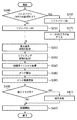
図1は特許文献2に記載されるインク残量検知方式と同様の方式である従来のインク残量検知方式の一例を示すフローチャートである。
FIG. 1 is a flowchart showing an example of a conventional ink remaining amount detection method which is the same method as the ink remaining amount detection method described in
まず、ステップS110では、画像形成等の記録動作のためのインク吐出又は記録ヘッドの回復動作で行われる予備吐出若しくはインク吸引により消費される各インクのインク消費量を、インク吐出のために印加されるパルスのパルス数に換算して計数する。なお、本従来例では、上記吸引動作1回当たりのパルス数を、3×10⁶パルスと換算している。 First, in step S110, the ink consumption of each ink consumed by ink ejection for recording operations such as image formation or preliminary ejection or ink suction performed in the recovery operation of the recording head is applied for ink ejection. Convert to the number of pulses to be counted. In this conventional example, the number of pulses per one suction operation is converted to 3 × 10 6 pulses.
ステップS120では、ステップS110にて計数されたパルス数が所定パルス数に達したか否かを判断する。本従来例ではこの所定パルス数を15×106パルスに設定している。この判断で、所定パルス数に達していないときは引き続き計数を行い、所定パルスに達した場合には、ステップS130においてインクタンクを搭載したキャリッジをフォトインタラプタが設けられる場所に移動してインクタンクの光反射率(出力値)を測定する。 In step S120, it is determined whether or not the number of pulses counted in step S110 has reached a predetermined number of pulses. In this conventional example, the predetermined number of pulses is set to 15 × 10 6 pulses. In this determination, if the predetermined number of pulses has not been reached, the counting is continued. If the predetermined number of pulses has been reached, the carriage on which the ink tank is mounted is moved to the place where the photo interrupter is provided in step S130, and the ink tank The light reflectance (output value) is measured.
そして、次に、ステップS140で、過去3回の出力値とステップS130で測定した出力値から各出力値間の変化量を求めてそれらの合計値を求める。ステップS150では、この出力変化量の合計値と前回の同様に計算された合計値を比較し、前回求めた合計値よりも所定値であるα以上上昇したかを判別する。 Then, in step S140, the amount of change between the output values is obtained from the past three output values and the output value measured in step S130, and the total value thereof is obtained. In step S150, the total value of the output change amounts is compared with the previously calculated total value, and it is determined whether or not the total value obtained in the previous time has increased by a predetermined value α or more.
ここで、α以上上昇していないと判断したときにはステップS190でパルス数をカウントするカウンタをクリアしてステップS110に戻りパルス数の計数と出力値の取得を再び実行する。また、α以上上昇していると判断した場合にはステップS160に進み、インクタンクのインク残量が残り少なくなったことを表示する。そして、さらにステップS170で記録動作を中断しインクタンクの交換を待機する等の処理を行う。そして、上記パルス数をカウントするカウンタをクリアする(ステップS148)。このように、本インク残量検知動作では所定量のインクを消費する毎にフォトインタラプタによる出力値測定及びそれに基づく判断を行い、これにより定期的なインク残量検知動作を可能としている。 Here, when it is determined that the value has not increased by α or more, the counter for counting the number of pulses is cleared in step S190, and the process returns to step S110 to execute the counting of the number of pulses and the acquisition of the output value again. On the other hand, if it is determined that the amount has risen by α or more, the process proceeds to step S160 to display that the remaining amount of ink in the ink tank is low. Further, in step S170, processing such as interrupting the recording operation and waiting for ink tank replacement is performed. Then, the counter for counting the number of pulses is cleared (step S148). In this way, in the present ink remaining amount detecting operation, every time a predetermined amount of ink is consumed, the output value measurement by the photo interrupter and the determination based on the measurement are performed, thereby enabling the periodic ink remaining amount detecting operation.
一方、この他のタイミングにもインク残量検知動作を行う場合がある。例えば、記録装置の電源が投入(ON)された後に、記録装置の初期化動作の1つとして、インク残量の検知が行われている。これは、記録装置の電源が切断(OFF)されており記録装置にインク残量の変更が記憶できない間、インクタンクや記録ヘッドの着脱、インクの補充、インクの蒸発等によりインク残量の増減に変化があった場合に備える為である。そして、記録装置の電源が投入された後にインク残量検知を行って、記録装置に記憶されているインク残量との整合性を確認している。 On the other hand, the remaining ink amount detecting operation may be performed at other timings. For example, after the printing apparatus is turned on (ON), the remaining amount of ink is detected as one of the initialization operations of the printing apparatus. This is because the remaining amount of ink is increased or decreased by attaching / detaching an ink tank or recording head, refilling ink, evaporating ink, etc. while the power of the recording device is off (OFF) and the change of the remaining amount of ink cannot be stored in the recording device. This is to prepare for the case where there is a change. Then, after the recording apparatus is turned on, the remaining amount of ink is detected to check the consistency with the remaining amount of ink stored in the recording apparatus.
図2は、電源投入後の記録装置の初期化動作の一例を示す図である。 FIG. 2 is a diagram illustrating an example of the initialization operation of the recording apparatus after the power is turned on.
まず、ステップS240で、記録装置のハードパワーのOFF又はONを行うかどうかを判断する。ハードパワーが既にONであれば、ソフトパワーをONし(ステップS250)、ステップS300に進む。ハードパワーがOFFであればハードパワーをONし、ステップS260によりソフトパワーをONし、ステップS270でハードパワーONのフラグをたてて、ステップS320に進む。 First, in step S240, it is determined whether to turn off or on the hard power of the recording apparatus. If the hard power is already ON, the soft power is turned ON (step S250), and the process proceeds to step S300. If the hard power is OFF, the hard power is turned ON, the soft power is turned ON in step S260, a hard power ON flag is set in step S270, and the process proceeds to step S320.
ステップS320で、記録ヘッドの走査方向である主走査に対して副走査となる記録媒体の搬送について、副走査に関する初期化処理として機構動作が問題なく行われるように初期化し、また記録媒体が所定の初期位置に搬送されるように設定する。次にステップS330で、リフトアップ初期化処理として記録ヘッド部の上下動作が問題なく行われるように初期化し、また記録ヘッドが所定の初期位置に位置するよう設定する。続いて、ステップS340で、回復系イニシャル処理として、記録ヘッドを良好な状態にクリーニングするために使用するポンプやワイパー、キャップが問題なく動作するように初期化し、またこれらを所定の初期位置に設定する。これらステップS320、S330、S340によって本体機構の初期化動作をした後、ステップS380で、タンク検知として、インクタンクが正しく装着されているかの確認がされる。そして、ステップS390で、インク残量検知として、インクタンク内のインク残量の確認動作が行われる。その後、ステップS400で前回使用時からの経過時間などから記録ヘッドを良好な状態にクリーニングする吸引作業が必要に応じて(ステップS410)行われ、ステップS420で記録動作が開始される。
しかしながら、光学的手段を用いて行うインク残量検知動作は光反射率の検知のためにキャリッジをフォトインタラプタ等のインク残量センサが設けられる位置まで移動させる動作が必要となる。 However, the remaining ink amount detecting operation performed using an optical means requires an operation of moving the carriage to a position where an ink remaining amount sensor such as a photo interrupter is provided in order to detect light reflectance.
上記特許文献1においても、インクタンク内のインク残量を検知する構成が示されているが、インク残量検知をするためにインクタンクが装着された記録ヘッドをインク残量センサの位置まで移動する必要があり、移動のための時間がかかってしまう。このため、ユーザが記録装置の電源投入直後に記録しようとした場合でも、記録が開始される前に、インク残量検知の動作のための時間を待つ必要があった。 Japanese Patent Application Laid-Open No. 2005-228561 also shows a configuration for detecting the remaining amount of ink in the ink tank. However, in order to detect the remaining amount of ink, the recording head equipped with the ink tank is moved to the position of the remaining ink sensor. It takes time to move. For this reason, even when the user tries to record immediately after turning on the power of the recording apparatus, it is necessary to wait for the time for the operation of detecting the remaining amount of ink before the recording is started.
本発明は上記従来の問題点を解消するためになされたものであり、その目的とするところは、電源投入から記録開始までに要する時間を少なくすることが可能な記録装置を提供することにある。 The present invention has been made to solve the above problems, it is an object to provide a record apparatus capable of reducing the time from power-up to start recording is there.
上記目的を達成するため、本発明は、記録装置であって、インクを吐出する記録ヘッドに供給されるインクを収容するためのインクタンクと、前記記録ヘッドに記録動作を実行させるための回路への電力供給を切断するにあたり、前記記録装置を動作可能な状態から記録動作不可能な状態にする動作の実行において異常が発生したか否かを示す情報を記憶するための不揮発性の記憶素子と、前記インクタンク内のインク残量を検知する検知手段と、前記検知手段を制御する制御手段とを備え、前記制御手段は、前記不揮発性の記憶素子に前記異常が発生したことを示す情報が記憶されている場合は、前記回路への電力供給が開始された後で前記記録動作を実行前の初期動作において前記検知手段に検知動作を行わせ、前記不揮発性の記憶素子に前記情報が記憶されていない場合は前記初期動作において前記検知手段に検知動作を行わせないよう制御することを特徴とする。 In order to achieve the above object, the present invention provides a recording apparatus comprising: an ink tank for storing ink supplied to a recording head that ejects ink; and a circuit for causing the recording head to perform a recording operation. Upon cutting the power supply, a non-volatile memory for storing information indicating whether an abnormality has occurred Oite the execution of the operation of the recording inoperable from operable state the recording device comprising a device, a detection means for detecting the remaining amount of ink in the ink tank, and control means for controlling said detection means, said control means indicates that the abnormality occurs in the non-volatile storage elements If the information is stored, to perform the detection operation in the detection unit in an initial operation before performing the recording operation after the power supply to the circuit is started, the non-volatile storage elements If the information is not stored and the control unit controls so as not to perform the detection operation in the detection means in the initial operation.
本発明によれば、インクタンク内のインク残量を検知する構成をもつインクジェット記録装置において、電源投入直後に記録動作を短時間で開始できるインクジェット記録装置及びそのインク残量検知方法を提供することが可能となる。 According to the present invention, in an inkjet recording apparatus having a configuration for detecting the remaining amount of ink in an ink tank, an inkjet recording apparatus capable of starting a recording operation in a short time immediately after power-on and an ink remaining amount detection method thereof are provided. Is possible.
以下、添付図面を参照して、本発明の好適な実施例について詳細に説明する。 Hereinafter, preferred embodiments of the present invention will be described in detail with reference to the accompanying drawings.
なお、この明細書において、「記録」とは、文字、図形等有意の情報を形成する場合のみならず、有意無意を問わず、広く記録媒体上に画像、模様、パターン等を形成する、又は媒体の加工を行う場合も表すものとする。また、人間が視覚で知覚し得るように顕在化したものであるか否かを問わない。 In this specification, “recording” not only forms significant information such as characters and graphics, but also forms images, patterns, patterns, etc. on a wide variety of recording media, regardless of significance, or It also represents the case where the medium is processed. It does not matter whether it has been made obvious so that humans can perceive it visually.
また、「記録媒体」とは、一般的な記録装置で用いられる紙のみならず、広く、布、プラスチック・フィルム、金属板、ガラス、セラミックス、木材、皮革等、インクを受容可能なものも表すものとする。 “Recording medium” refers not only to paper used in general recording apparatuses but also widely to cloth, plastic film, metal plate, glass, ceramics, wood, leather, and the like that can accept ink. Shall.
また、「インク」とは、上記「記録」の定義と同様広く解釈されるべきもので、記録媒体上に付与されることによって、画像、模様、パターン等の形成又は記録媒体の加工、或いはインクの処理に供され得る液体を表すものとする。インクの処理としては、例えば記録媒体に付与されるインク中の色剤の凝固又は不溶化させることが挙げられる。 The term “ink” should be broadly interpreted in the same way as the definition of “recording”. When applied to a recording medium, the “ink” forms an image, a pattern, a pattern, or the like, or processes the recording medium. It represents a liquid that can be subjected to the treatment. Examples of the ink treatment include solidification or insolubilization of the colorant in the ink applied to the recording medium.
図3は、本発明の一実施例に係るカラーインクジェットプリンタの記録部の概略構成を示す斜視図である。 FIG. 3 is a perspective view illustrating a schematic configuration of a recording unit of a color inkjet printer according to an embodiment of the present invention.
図3において、104は複数の吐出口を配列し各吐出口からインク滴を吐出する記録ヘッドを有したヘッドユニットをキャリッジ103に着脱自在に装着するための固定レバーであり、ヘッドユニットはこの固定レバー104内に格納される。本実施例の場合、ヘッドユニットは、イエロー(Y)、マゼンタ(M)、シアン(C)及びブラック(K)の4色のインクの記録ヘッドを一体に有している。この記録ヘッドから吐出されるインク滴により記録媒体としての例えば記録紙110上にドットが形成され、これにより、カラー画像等の記録を行うことが可能となる。なお、102YはYインクを、102MはMインクを、102CはCインクを、102KはKインクを、夫々内包したインクタンクである。
In FIG. 3,
キャリッジ103は、キャリッジ駆動用モータ113の駆動力がモータプーリ112、従動プーリ111及びタイミングベルト116を介して伝達されることにより、ガイド軸105に沿って図中矢印a及びb方向へ移動することが可能なように設けられている。一方、記録紙110は、その搬送方向において上流側及び下流側に設けられた2組の搬送ローラ106及び107並びに108及び109によって搬送される。
The
また、記録紙110は記録ヘッドの吐出口と対向する位置において平坦な記録面を形成するよう、その裏面をプラテン(不図示)により支持されている。以上の、キャリッジ103の移動による記録ヘッドの走査及び搬送ローラ106から109による記録紙110の搬送により、記録紙110の所定領域に順次画像等が形成されて行く。
Further, the back surface of the
なお、これら記録のための画像データ等は、フレキシブルケーブル(不図示)を介してプリンタ本体の制御部をなす電気回路から記録ヘッドの駆動回路に伝送される。 Note that the image data and the like for recording are transmitted from an electric circuit forming a control unit of the printer body to a drive circuit of the recording head via a flexible cable (not shown).
記録ヘッドのホームポジションには、回復ユニット120が配設される。回復ユニット120は、各インクの記録ヘッド夫々に備えられている吐出口列に対応して配置された4個のキャップ121と各キャップにチューブ等で接続されたポンプユニット(不図示)とを備えている。キャップ121は、上下方向に昇降可能であり、記録ヘッドがホームポジションにあるときにそれぞれ対応する記録ヘッドの吐出口を配設した面(以下、吐出口面ともいう)に密着して吐出口を覆う(キャッピングをする)ように構成されている。このキャッピングにより、吐出口内のインクの蒸発による増粘又は固着が防止され、これにより吐出不良の発生を未然に防止することができる。また、インクタンクの交換時や記録ヘッドの吐出不良が生じた場合には、上述のキャッピング状態のもとでポンプユニットを作動させてキャップ内を負圧とし、この負圧による吸引力で吐出口からインクを吸い出し新しいインクを導く吸引回復処理が行われる。さらに、回復ユニット120には、キャップ121と記録領域との間に、記録ヘッドの吐出口面に付着したインク滴等を拭き取り吐出口面を清掃するためのワイパーブレード122が設けられている。
A
前記キャップ121とワイパーブレード122との間には、光学的にインク残量を検知するためのフォトインタラプタ123が設けられる。このフォトインタラプタ123は、後述するようにキャリッジ103上の各インクタンクの底面に光を照射するとともにその反射光を受光しインクタンクの光反射率を測定するために用いられる。すなわち、キャリッジ103を移動させて各インクタンクをフォトインタラプタに対向させることにより各インクタンクの光反射率を測定できるように構成されている。
A
図4は、キャリッジ103に搭載されるヘッドユニット及びインクタンクを示す斜視図である。
FIG. 4 is a perspective view showing a head unit and an ink tank mounted on the
キャリッジ103には、K、C、M及びYのインクをそれぞれ吐出する4つの記録ヘッド(不図示)を格納したヘッドユニット101が搭載されている。さらに、それぞれ対応する記録ヘッドに供給するインクを内包したインクタンク102K、102C、102M及び102Yが搭載されている。4つの記録ヘッドは、それぞれ吐出口を具備しており、これらの吐出口からインク滴が吐出される。また4つのインクタンクは各々キャリッジ103に着脱可能に装着されるものであり、インクがなくなった時点で新たなインクタンクに交換することができる。
The
ヘッドユニット101のカバー部材をなす固定レバー104は、ヘッドユニット101をキャリッジ103に位置決めし、固定するためのものである。キャリッジ103の一部に設けられたボス103bと固定レバー104の穴104aとが回転自在に嵌合することにより、固定レバー104の開閉が可能となり、これによって記録ヘッド312の交換が可能になる。また、固定レバー104を閉じることにより記録ヘッド312と装置本体との電気信号等の接続が可能となる。
A fixing
図5は、上述したインクジェットプリンタの制御構成を示すブロック図である。 FIG. 5 is a block diagram showing a control configuration of the above-described inkjet printer.
図5おいて、301は、インクジェットプリンタ全体を制御するためのシステムコントローラである。システムコントローラ301の内部には、マイクロプロセッサ(MPU)、制御プログラムが収納されている記憶素子(ROM)、MPUが処理を行う際に使用する記憶素子(RAM)、EEPROM等の不揮発性で書換え可能な記憶素子等が設けられている。
In FIG. 5,
302は、キャリッジ103を移動させるためのモータ304を駆動するドライバであり、同様に303は、記録媒体を搬送するためのモータ305を駆動するドライバである。すなわち、モータ304及び305は、対応するドライバからの速度、移動距離などの情報を受け取り動作する。
307は、ホストコンピュータ306から送られるデータを一時的に格納するための受信バッファであり、システムコントローラ301によりデータが読み込まれるまでデータを蓄積しておく。また、308は、記録すべきデータをイメージデータに展開するためのフレームメモリであり、システムコントローラ301が受信バッファ307から読込んだデータに基づいて展開するイメージデータを格納する。このフレームメモリ308は、記録に必要な分のメモリサイズを有しており、本実施例では記録媒体1枚分のイメージデータを記憶可能なものである。しかし、本発明の適用がこのフレームメモリのサイズには限定されないことは勿論である。さらに、309は、記録ヘッドの走査による1ライン分の記録データを記憶するためのメモリであり、記録ヘッドの吐出口数に対応した記憶容量を有している。
A
310は、システムコントローラ301からの指令により記録ヘッドの駆動を制御する記録制御部であり、例えば記録ヘッドの吐出周波数や吐出数等を制御する。また、ここでは、記録ヘッド312K、312C、312M及び312Yそれぞれによるインク滴の吐出数と、記録ヘッドの回復のために行われる吸引回数を計数し、インク毎のインク消費量をインク滴数(パルス数)に換算する処理も行われる。311は、記録制御部310の制御により各記録ヘッド312K、312C、312M及び312Yを駆動してインク吐出を行わせるドライバである。
A
313は、上述した図3のフォトインタラプタ123からの出力を得てその出力値に応じたデジタル値に変換する検出部である。
図6は、上述した記録ヘッド312及びインクタンク102のより詳細な構成を示す模式図であり、また、図7は記録ヘッド312の縦断面図である。
FIG. 6 is a schematic diagram showing a more detailed configuration of the
これら図に示すように、記録ヘッド312にはインク滴を吐出させるための吐出口2が配置されている。吐出口2にはインクタンク102からその供給口4、供給管5、共通液室13及びインク流路17を介してインクが供給される。吐出口2に供給されたインクは、Al等よりなるベース板14に取付けられたヒーターボード15上に形成されたヒーター16によって加熱され、この加熱により生成した気泡によって吐出口2より微小液滴となって吐出される。
As shown in these drawings, the
インクタンク102には上述の供給口4のほかにインク消費に伴う気液交換を行うための大気連通口6が設けられている。また、インクタンク102の内部にはポリウレタン等のインク吸収体7が収められ、その毛管力により記録の際に適切な負圧を発生させ安定したインク滴の吐出を実現させている。
In addition to the
記録ヘッド312及びインクタンク102は上述したようにキャリッジ103に搭載され、このキャリッジと摺動可能に係合するシャフト9及び10に沿って走査される。また、図3に示したように、キャリッジ103の走査方向の所定位置にはLED素子と受光素子とが一体になった反射型フォトインタラプタ123が設けられている。このフォトインタラプタ123は、上記所定位置においてキャリッジ103に開けられた穴12を通してインクタンク102の吸収体7の底面に光を照射することができる。このフォトインタラプタ123のLEDはカラープリンターで通常使用される黒、シアン、マゼンタ、イエローの4色のインク何れにも透過性を有する赤外光を発光し、受光素子もこのLEDが発光する赤外光の反射光の波長に対して十分な感度を有している。ここで、フォトインタラプタ123をキャリッジ103とは別個に設けることにより、キャリッジ103とインクジェットプリンタ本体との間でフォトインタラプタ用の給電線や信号線などが不要となる。
The
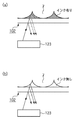
図8(a)及び(b)は、インクタンク102の下面に対しフォトインタラプタ123が光照射している様子を模式的に示す図である。図8(a)に示すように、インクタンク102にインクが十分あるときはインクタンク102の壁面と吸収体7の隙間はインクで充填されている。また、図8(b)に示すように、インクタンク102にインクが無いか少なくなっているときはインクタンク102の壁面と吸収体7の隙間には空気が入り込んでいる。その結果、図8(b)の状態は図8(a)の状態に比べフォトインタラプタ123より照射した光の反射率が大きくなる。例えば、インクタンク102及び吸収体7の材質をプラスチックとしてその屈折率を約1.5とし、インクの屈折率を約1.4とすると、図8(b)の状態での光の反射率は、図8(a)の状態での光の反射率の約40倍あることになる。このため、この差によってインクの有無を検出することができる。
FIGS. 8A and 8B are diagrams schematically illustrating a state in which the
なお、実際にはフォトインタラプタ123が光を照射している領域は点ではなくある所定の大きさの領域であり、その領域において徐々にインクが無くなることを検出するのでフォトインタラプタ123の出力も連続的に変化する。
Note that the area where the
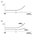
図9(a)はフォトインタラプタ123の出力が連続的に変化する様子を模式的に表したものである。図9(a)は、初期状態からインクタンク102のインクが無くなるまで記録を行ったとき、すなわち、記録された記録媒体の記録枚数が増加していったとき(横軸)のフォトインタラプタ123の出力(縦軸)の関係を示している。記録枚数がX枚に至るまではフォトインタラプタ123の出力はほぼ一定であるが、記録枚数がX枚を過ぎた後にフォトインタラプタ123が光を照射する領域のインクが減少し、フォトインタラプタ123の出力が上昇することを示している。したがって、X枚の記録枚数を過ぎた後、所定量のインクを消費する毎にフォトインタラプタの出力値を測定し、その消費の前後の出力変化を検知すれば、その変化率と図9(a)に示す関係からインクタンク102のインク残量を知ることが可能となる。
FIG. 9A schematically shows how the output of the
なお、図9(b)はフォトインタラプタ123とインクタンク102との距離に応じて出力特性の違いを示す図である。この図からも明らかなように、設定される距離にかかわらず、出力の変化点である記録枚数Xの値はほとんど変わらないことがわかる。
FIG. 9B is a diagram showing a difference in output characteristics depending on the distance between the
図10は、異なる4つのインクタンクでの実際の出力特性を示したものである。これらのインクタンクを用いて所定の画像を記録した場合に、所定消費量である5×10⁶パルスに相当するインク消費量毎の出力値の測定結果をプロットしたものである。なお、縦軸の出力値は、LEDをオフとした時のフォトインタラプタからの出力(暗電圧)からLEDをオンとした時のフォトインタラプタからの出力(明電圧)を差し引いたものを示している。 FIG. 10 shows actual output characteristics with four different ink tanks. When a predetermined image is recorded using these ink tanks, the measurement result of the output value for each ink consumption corresponding to 5 × 10 6 pulses, which is the predetermined consumption, is plotted. Note that the output value on the vertical axis indicates a value obtained by subtracting the output (bright voltage) from the photo interrupter when the LED is turned on from the output (dark voltage) from the photo interrupter when the LED is turned off. .
図10より明らかなように、インクタンクによって出力値が異なっているため、各インクタンクの出力値について単一の閾値を定めてインク残量を検知することは困難である。しかし、各インクタンクについて出力値の変化量(変化率)を測定すれば、各インクタンクのインク残量を検知することができる。 As is apparent from FIG. 10, since the output value differs depending on the ink tank, it is difficult to detect the remaining ink amount by setting a single threshold value for the output value of each ink tank. However, if the amount of change (change rate) of the output value is measured for each ink tank, the remaining amount of ink in each ink tank can be detected.
一方、上述したように記録枚数がX枚に至るまではフォトインタラプタ123の出力はほぼ一定である。これは、記録枚数がX枚に至るまではフォトインタラプタ123から光が照射される領域に十分なインクがあるためである。このことを利用し、インク残量検知が行われた後に新しいインクタンクへの交換が行われた場合、出力変化が少ないことを検知した後自動的に、インク残量が少ない旨の報知をすることを一定期間停止させることもできる。
On the other hand, as described above, the output of the
なお、本発明は、記録ヘッド312とインクタンク102とが独立して着脱可能な記録装置の他、記録ヘッド312とインクタンク102とが一体型のヘッドカートリッジを用いた記録装置にも適用可能である。
The present invention can be applied to a recording apparatus using a head cartridge in which the
図12は、インクタンク102と記録ヘッド312とが一体的に形成されたヘッドカートリッジの構成を示す外観斜視図である。図12において、点線Kはインクタンク102と記録ヘッド312の境界線である。フォトインタラプタ123から出力された光がインクタンク102に照射されてインク残量検知が行われることは上記のインクタンク102と記録ヘッド312とが分離するタイプのヘッドカートリッジにおける場合と同様である。ヘッドカートリッジにはこれがキャリッジに搭載されたときには、キャリッジ側から供給される電気信号を受け取るための電極(不図示)が設けられている。そして、この電気信号によって、前述のように記録ヘッドが駆動されてインクが吐出される。なお、図12において、500はインク吐出口列である。
FIG. 12 is an external perspective view showing a configuration of a head cartridge in which the
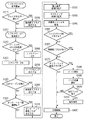
(第1の実施例)
図11は、記録装置の電源を切断してから、電源投入し、その後記録を開始するまでに行われる初期動作の一例を説明するものである。なお、本明細書では、電源より電力が記録装置に供給される状態をハードパワーONのステータスといい、電源より電力が記録装置に供給されない状態をハードパワーOFFのステータスという。また、ハードパワーがONのステータスで記録装置が動作可能な状態をソフトパワーONのステータスという。また、ハードパワーがONのステータスで、記録を実行するための回路等への電源供給が行われておらず、記録装置が記録動作不可能な状態をソフトパワーOFFのステータスという。さらに、電源切断とは、ハードパワーONの状態のままソフトパワーオフのみを実行する処理を示すものである。さらにまた、電源投入とは、ハードパワーONの状態であればソフトパワーオンが行われる処理、ハードパワーOFFの状態であればハードパワーオンとソフトパワーオンとが行われる処理を示すものである。
(First embodiment)
FIG. 11 illustrates an example of an initial operation performed after the recording apparatus is turned off, the power is turned on, and recording is started thereafter. In this specification, a state in which power is supplied from the power source to the recording apparatus is referred to as a hard power ON status, and a state in which power is not supplied from the power source to the recording apparatus is referred to as a hard power OFF status. Further, a state in which the recording apparatus can operate with the hard power ON status is referred to as a soft power ON status. A state in which the power is not supplied to a circuit or the like for executing the recording with the hard power ON status and the recording apparatus cannot perform the recording operation is called a soft power OFF status. Further, the power-off means a process of executing only the soft power off while the hard power is on. Furthermore, power-on indicates a process in which soft power-on is performed when the hard power is on, and a process in which hard power on and soft power on are performed in the hard power off state.
記録装置の電源切断時となるソフトパワーOFF処理を開始した際に、まず、ステップS210で、フェイタルエラーが発生した場合、異常終了と判断する。そしてその判断結果に基づいて、ステップS220において異常終了フラグをたて、システムコントローラ301の不揮発性で書換え可能な不揮発性の記憶素子に格納し、ソフトパワーOFFの処理を完了する(ステップS230)。ステップS210でフェイタルエラーが発生しなかった場合、そのままソフトパワーOFFの処理を完了する(ステップS230)。
When a soft power OFF process is started when the recording apparatus is powered off, first, if a fatal error occurs in step S210, it is determined that the process has ended abnormally. Based on the determination result, an abnormal end flag is set in step S220 and stored in the non-volatile rewritable non-volatile storage element of the
なお、本例では、上記のフェイタルエラーとして、例えば以下に挙げるような異常動作を検知する。ソフトパワーOFFの命令が出されると記録装置の個々の機構は決められた位置に設定されるよう動作するが、その動作途中でハードパワーがOFFされ、その動作を完了できなかった場合がある。また、紙詰まりエラーが出たままソフトパワーOFFされた場合がある。また、ソフトパワーOFFの命令が出された際の動作時にインクタンクの誤装着が認められた場合がある。このような場合、本例では、フェイタルエラーとして検知して、その情報を不揮発性の記憶素子に記憶する。 In this example, as the above fatal error, for example, an abnormal operation as described below is detected. When a soft power OFF command is issued, the individual mechanisms of the recording apparatus operate so as to be set at a predetermined position. However, in some cases, the hard power is turned OFF during the operation and the operation may not be completed. In some cases, the soft power is turned off with a paper jam error. In some cases, the ink tank is erroneously installed during the operation when the soft power OFF command is issued. In such a case, in this example, it is detected as a fatal error, and the information is stored in a nonvolatile storage element.
ステップS240からステップS270までは、図2と共通するため説明を省略する。なお、ステップS240においてハードパワーがON処理を行うことが判断され、ハードパワーオンされると、その情報(ハードパワーONのフラグ)は、ステップS270においてシステムコントローラ301の不揮発性で書換え可能な記憶素子に格納される。
Steps S240 to S270 are the same as those in FIG. If it is determined in step S240 that the hard power is to be turned on, and the hard power is turned on, the information (hard power on flag) is stored in the nonvolatile memory of the
その後、ステップS350で、ハードパワーONのフラグが有るか否かを確認する。ハードパワーONのフラグが有るとの確認結果であった場合はステップS380に進み、ハードパワーONのフラグが無いとの確認結果であった場合はステップS360に進む。ステップS360では、異常終了フラグが有るか否かを確認する。異常終了フラグが有るとの確認結果であった場合はステップS380に進み、異常終了フラグが無いとの確認結果であった場合はステップS370に進む。なお、ステップS380からステップS420までは、図2と共通するため説明を省略する。 Thereafter, in step S350, it is confirmed whether or not there is a hard power ON flag. If it is a confirmation result that there is a hard power ON flag, the process proceeds to step S380, and if it is a confirmation result that there is no hard power ON flag, the process proceeds to step S360. In step S360, it is confirmed whether or not there is an abnormal end flag. If it is a confirmation result that there is an abnormal end flag, the process proceeds to step S380, and if it is a confirmation result that there is no abnormal end flag, the process proceeds to step S370. Steps S380 to S420 are the same as those in FIG.
このように、インク残量検知を行うステップであるステップS390を実施するのは、次の条件の少なくとも一方の条件を満たす場合であり、そうでない場合は、初期動作としてインク残量検知を行うことを抑止する。 In this way, step S390, which is a step for detecting the remaining amount of ink, is performed when at least one of the following conditions is satisfied. Otherwise, the remaining amount of ink is detected as an initial operation. Is suppressed.
インク残量検知を行う第1の条件は、記録を開始しようとする際に、ハードパワーがOFFされていて、ハードパワーONの処理を要した場合である。また、インク残量検知を行う第2の条件は、前回の記録等が終了しソフトパワーOFFする際にフェイタルエラーが発生していた場合である。 The first condition for detecting the remaining amount of ink is when the hard power is turned off and the hard power on process is required when starting printing. The second condition for detecting the remaining amount of ink is when a fatal error has occurred when the previous recording or the like is completed and the soft power is turned off.
前記第1の条件について、具体的には、例えば、前回の記録等が終了し、正常にソフトパワーOFFされた後ハードパワーもOFFされ、記録を開始しようとする際までハードパワーがOFFされていた場合がある。つまり、ハードパワーオフの状態では記録装置に電源が供給されていないため、インクタンクの着脱など記録装置の変化を検知できない。したがって、本例では、第1の条件を満たすような場合に、初期化シーケンスにおいてインク残検を実施するようにしている。 For the first condition, specifically, for example, after the previous recording or the like is completed and the soft power is normally turned off, the hard power is also turned off, and the hard power is turned off until the recording is started. There is a case. That is, since no power is supplied to the printing apparatus in the hard power-off state, changes in the printing apparatus such as ink tank attachment / detachment cannot be detected. Therefore, in this example, when the first condition is satisfied, the residual ink detection is performed in the initialization sequence.
このように本実施例では電源投入時の初期化シーケンスにおいて、ソフトパワーOFFの命令が出された際の動作が正常に終了し、且つハードパワーオン処理が実行されなかった場合にインク残量検知を省略することにより短時間で記録を開始することができた。 As described above, in this embodiment, in the initialization sequence when the power is turned on, the remaining amount of ink is detected when the operation when the soft power OFF command is issued ends normally and the hard power on process is not executed. By omitting, recording could be started in a short time.
なお、本実施例においては、上記の第1、第2の条件のうち少なくとも一方の条件を満たした場合には、インクの残量検知を実行するようにした。しかし、本発明はこの構成に限られず、記録開始前にインク残検を実施するか否かの条件を、いずれか一方の条件のみとして、さらに短時間で記録を開始できるようにしてもよい。 In this embodiment, the remaining amount of ink is detected when at least one of the first and second conditions is satisfied. However, the present invention is not limited to this configuration, and it may be possible to start recording in a shorter time by setting only one of the conditions as to whether or not to perform ink residual detection before starting recording.
(第2の実施例)
第1の実施例では、記録を開始しようとする際にハードパワーONの処理を要したか否かの条件、およびソフトパワーOFFする際にフェイタルエラーが発生していたか否かの条件に応じて、インク残量検知の実行を制御した。これに対し、本実施例では、第1の実施例の2条件に加えて、電源投入後の記録装置の状態を検知してインク残量検知を実行するか否かを決定する。具体的には、キャップがオープン状態となっているか否か、およびインクタンク、記録ヘッドに着脱された履歴があるかを検出して、インク残量検知を実行するか否かを決定する。
(Second embodiment)
In the first embodiment, depending on whether or not a hard power ON process is required when starting recording, and whether or not a fatal error has occurred when soft power OFF is performed. The execution of ink remaining amount detection was controlled. On the other hand, in this embodiment, in addition to the two conditions of the first embodiment, the state of the printing apparatus after the power is turned on is detected to determine whether or not to perform ink remaining amount detection. Specifically, it is determined whether or not the remaining ink amount detection is to be executed by detecting whether or not the cap is in an open state and whether there is a history of attachment or detachment of the ink tank or recording head.
以下の説明では、すでに第1の実施例で説明した構成、並びに制御方法については説明を省略し、本実施例の特徴的構成を中心に説明を行う。 In the following description, the description of the configuration and control method already described in the first embodiment will be omitted, and the description will focus on the characteristic configuration of the present embodiment.
図13は、本例において、記録装置の電源を切断してから、電源投入し、その後記録を開始するまでに行われる初期動作を説明するものである。 FIG. 13 illustrates an initial operation performed in this example from when the recording apparatus is turned off to when the recording apparatus is turned on and thereafter recording is started.
記録装置の電源切断時となるソフトパワーOFF処理、および電源投入時のハードパワーON処理に係わるステップS200からS270までは、既に説明した通りであるので、ここでの説明は省略する。 Steps S200 to S270 related to the soft power-off process when the recording apparatus is turned off and the hard power-on process when the power is turned on are as described above, and thus the description thereof is omitted here.
ステップS270の後、ステップS280に進むと、ソフトパワーONした際にキャップ(CAP)がオープン状態であったか否かを判断し、キャップがオープン状態であった場合は、ステップS290で異常終了フラグをたてステップS300に進む。キャップがオープン状態でなかった場合は、そのままステップS300に進む。 After step S270, when the process proceeds to step S280, it is determined whether or not the cap (CAP) is open when the soft power is turned on. If the cap is open, an abnormal end flag is set in step S290. Then, the process proceeds to step S300. If the cap is not open, the process proceeds directly to step S300.
そして、ステップS300でインクタンクや記録ヘッドが着脱された履歴があるかを確認する。その後、着脱された履歴があればインクタンク及び記録ヘッドの着脱フラグをたて、システムコントローラ301の不揮発性の記憶手段に記憶する(ステップS310)。その後、ステップS320に進み着脱された履歴が無ければそのままステップS320に進む。 In step S300, it is confirmed whether there is a history of attaching or detaching the ink tank or the recording head. Thereafter, if there is a history of attachment / detachment, an attachment / detachment flag for the ink tank and recording head is set and stored in the nonvolatile storage means of the system controller 301 (step S310). Thereafter, the process proceeds to step S320, and if there is no history of attachment / detachment, the process proceeds to step S320 as it is.
ステップ320からS350までの処理は、第1の実施例の処理と同様なため説明を省略するが、本実施例でも、ステップS350において、記録開始時にハードパワーON処理を実行した場合には、インク残検を行うようにしている。
The processing from
ステップ360では、異常終了フラグが有るか否かを確認する。異常終了フラグが有るとの確認結果であった場合はステップS380に進み、異常終了フラグが無いとの確認結果であった場合はステップS370に進む。なお、第1の実施形態では、ソフトパワーOFF処理の際にフェイタルエラーが発生した場合のみ、S360で異常終了フラグありと判断され、ステップS390においてインク残量検知が実施されていた。これに対し、本例では、S280により、ソフトパワーON時にキャップがオープン状態であった場合でも異常終了フラグをたてている。したがって、ステップ360では、ソフトパワーOFF処理の際にフェイタルエラーが発生した場合に加えて、ソフトパワーON時にキャップがオープン状態であった場合も、インク残量検知が行われるようにステップS390へと進む。
In
ステップS370では、インクタンク又は記録ヘッドの着脱フラグが有るか否かを確認する。インクタンク又は記録ヘッドの着脱フラグが有るとの確認結果であった場合はステップS380に進み、インクタンク又は記録ヘッドの着脱フラグが無いとの確認結果であった場合はステップS420に進み記録を開始する。なお、ステップS380からステップS420までは、既に説明した通りであり、その説明を省略する。 In step S370, it is confirmed whether there is an ink tank or printhead attachment / detachment flag. If it is confirmed that there is an ink tank or recording head attachment / detachment flag, the process proceeds to step S380. If it is confirmed that there is no ink tank or recording head attachment / detachment flag, the process proceeds to step S420 to start recording. To do. Steps S380 to S420 are as described above, and the description thereof is omitted.
このように、本実施例では、電源投入後の記録装置の状態を確認し、キャップがオープン状態となっている場合、およびインクタンク、記録ヘッドに脱着された履歴がある場合にもインク残量検知を実行するようにしている。 As described above, in this embodiment, the state of the printing apparatus after the power is turned on is checked, and the remaining amount of ink can be obtained even when the cap is in the open state and when there is a history of attachment / detachment to the ink tank and the print head. Detection is executed.
本実施例によれば、ソフトパワーOFF処理などが正常に行われたものの、その後の記録装置の運搬などでキャップが外れてしまった場合であっても、初期動作シーケンスにおけるインク残量検知を行うように構成されている。記録開始時にキャップが外れていた場合には記録ヘッド内のインクの水分が蒸発して、正常な記録が行えない虞もある。しかし、本実施形態では、電源投入時にキャップがオープン状態となっている場合にはインク残量検知を行うため、良好な画像記録を維持することが可能となる。 According to the present embodiment, the remaining amount of ink is detected in the initial operation sequence even when the soft power-off process or the like is normally performed but the cap is removed due to the subsequent transport of the printing apparatus or the like. It is configured as follows. If the cap is removed at the start of recording, the water in the ink in the recording head evaporates, and there is a possibility that normal recording cannot be performed. However, in the present embodiment, when the cap is open when the power is turned on, the remaining ink amount is detected, so that good image recording can be maintained.
また、前回の記録終了後から記録開始前までにインク残量の少ないインクタンクに交換される場合もあるが、本実施例はインクタンクに着脱履歴に応じてインク残検を実行する。これにより、インク残量が少ない状態で記録が実行され、かすれた画像が記録されるなどの弊害が抑制される。さらに、例えばインクタンクとインクジェットヘッドとが分離可能な記録装置においては、記録ヘッドが着脱された場合には、インクタンクと記録ヘッドとのジョイント部が大気に曝されてジョイント部からインクが蒸発する場合がある。そして、装着された記録ヘッドとインクタンクとのジョイント部でのインク供給不良が懸念される。このように、記録ヘッドが着脱された場合には、インク供給不良を起こさないために吸引回復が必要であり、本実施例においてはインク残量検知を行うようになっている。 In some cases, the ink tank is replaced with an ink tank with a small amount of remaining ink after the end of the previous recording and before the start of recording. In this embodiment, the remaining ink is detected in the ink tank according to the attachment / detachment history. Thereby, recording is executed in a state where the remaining amount of ink is low, and adverse effects such as recording of a faint image are suppressed. Further, for example, in a recording apparatus in which an ink tank and an ink jet head can be separated, when the recording head is attached or detached, the joint portion between the ink tank and the recording head is exposed to the atmosphere and the ink evaporates from the joint portion. There is a case. In addition, there is a concern about poor ink supply at the joint between the mounted recording head and the ink tank. Thus, when the recording head is attached / detached, suction recovery is required to prevent ink supply failure, and in this embodiment, ink remaining amount detection is performed.
本実施例では、電源投入後、キャップがオープン状態となっている場合、およびインクタンク、記録ヘッドに脱着された履歴がある場合には、インク残量検知を行う。このため、第1の実施例よりも記録開始までに時間を要する場合があるものの、良好な画像を記録できるようになる。なお、本発明は、キャップがオープン状態となっている場合、且つインクタンク、記録ヘッドに脱着された履歴がある場合のみインク残量検知の実行を抑止する構成に限られない。例えば、どちらか一方のみを、記録開始時にインク残量検知を実行するか否かの条件とすることで、さらに短時間で記録を開始できるようにしてもよい。 In this embodiment, the remaining amount of ink is detected when the cap is in an open state after the power is turned on, and when there is a history of attachment / detachment to / from the ink tank and recording head. For this reason, although it may take more time to start recording than in the first embodiment, a good image can be recorded. The present invention is not limited to a configuration that suppresses the detection of the remaining amount of ink only when the cap is in an open state and when there is a history of attachment / detachment to / from the ink tank and recording head. For example, by setting only one of the conditions as to whether or not to perform the remaining ink amount detection at the start of recording, the recording may be started in a shorter time.
(その他の実施例)
以上の各実施例は、特にインクジェット記録方式の中でも、インク吐出を行わせるために熱エネルギーを発生する手段を備え、前記熱エネルギーによりインクの状態変化を生起させる方式を用いることにより記録の高密度化、高精細化が達成できる。
(Other examples)
Each of the above-described embodiments includes a means for generating thermal energy to cause ink discharge, particularly among inkjet recording methods, and uses a method for causing a change in the state of ink by the thermal energy, thereby providing high density recording. And high definition can be achieved.
また、記録装置の記録モードとしては黒色等の主流色のみの記録モードだけではなく、記録ヘッドを一体的に構成するか複数個の組み合わせによって、異なる色の複色カラー、又は混色によるフルカラーの少なくとも1つを備えた装置とすることもできる。 In addition, the recording mode of the recording apparatus is not limited to a recording mode of only a mainstream color such as black, but at least of a multi-color of different colors or a full color by mixing colors by configuring a recording head integrally or by combining a plurality of recording heads. A device with one can also be provided.
さらに、本発明に係る記録装置の形態としては、コンピュータ等の情報処理機器の画像出力端末として一体又は別体に設けられるものの他、リーダ等と組み合わせた複写装置、さらには送受信機能を有するファクシミリ装置の形態を取るものであっても良い。 Further, as a form of the recording apparatus according to the present invention, a copying apparatus combined with a reader or the like, as well as a facsimile apparatus having a transmission / reception function, in addition to an image output terminal of an information processing device such as a computer, which is provided integrally or separately. It may take the form of
2 吐出口
102 インクタンク
123 フォトインタラプタ
301 システムコントローラ
310 記録制御部
312 記録ヘッド
2
Claims (5)
インクを吐出する記録ヘッドに供給されるインクを収容するためのインクタンクと、
前記記録ヘッドに記録動作を実行させるための回路への電力供給を切断するにあたり、前記記録装置を動作可能な状態から記録動作不可能な状態にする動作の実行において異常が発生したか否かを示す情報を記憶するための不揮発性の記憶素子と、
前記インクタンク内のインク残量を検知する検知手段と、
前記検知手段を制御する制御手段とを備え、
前記制御手段は、前記不揮発性の記憶素子に前記異常が発生したことを示す情報が記憶されている場合は、前記回路への電力供給が開始された後で前記記録動作を実行前の初期動作において前記検知手段に検知動作を行わせ、前記不揮発性の記憶素子に前記情報が記憶されていない場合は前記初期動作において前記検知手段に検知動作を行わせないよう制御することを特徴とする記録装置。 A recording device,
An ink tank for containing ink to be supplied to a recording head for discharging ink;
Upon cutting the power supply to the circuit for performing the recording operation on the recording head, whether Oite abnormality has occurred in execution of the operation of the recording inoperable from operable state the recording device A non-volatile storage element for storing information indicating
Detecting means for detecting the remaining amount of ink in the ink tank;
Control means for controlling the detection means,
In the case where information indicating that the abnormality has occurred is stored in the nonvolatile storage element , the control unit performs an initial operation before the recording operation is performed after power supply to the circuit is started. In the recording, the detection unit performs a detection operation, and when the information is not stored in the nonvolatile storage element, the detection unit is controlled not to perform the detection operation in the initial operation. apparatus.
前記制御手段は、前記回路への電力供給が開始された際に前記吐出口面が前記キャップによりキャッピングされていない場合は、前記初期動作において前記検知手段に検知動作を行わせるよう制御することを特徴とする請求項1に記載の記録装置。 A cap for capping the ejection port surface of the recording head;
The control means controls the detection means to perform a detection operation in the initial operation when the discharge port surface is not capped by the cap when power supply to the circuit is started. The recording apparatus according to claim 1 , wherein the recording apparatus is a recording apparatus.
前記不揮発性の記憶素子は、前記回路への電力供給が切断している間にインクタンクの着脱動作が行われたか否かを示す情報を記憶することが可能であり、
前記制御手段は、前記不揮発性の記憶素子にインクタンクの着脱動作が行われたことを示す情報が記憶されている場合は、前記初期動作において前記検知手段に検知動作を行わせるよう制御することを特徴とする請求項1又は2に記載の記録装置。 The ink tank is detachable from the main body of the recording apparatus,
The non-volatile storage element can store information indicating whether or not an ink tank is attached or detached while power supply to the circuit is cut off ,
When the information indicating that the ink tank has been attached / detached is stored in the nonvolatile storage element , the control means controls the detection means to perform the detection operation in the initial operation. the recording apparatus according to claim 1 or 2, characterized in.
前記不揮発性の記憶素子は、前記回路への電力供給が切断している間に記録ヘッドの着脱動作が行われたか否かを示す情報を記憶することが可能であり、
前記制御手段は、前記不揮発性の記憶素子に前記記録ヘッドの着脱動作が行われたことを示す情報が記憶されている場合は、前記初期動作において前記検知手段に検知動作を行わせるよう制御することを特徴とする請求項1乃至3のいずれか1項に記載の記録装置。 The recording head is detachable from the main body of the recording apparatus,
The nonvolatile storage element is capable of storing information indicating whether or not the recording head is attached or detached while the power supply to the circuit is cut off ,
The control unit controls the detection unit to perform the detection operation in the initial operation when information indicating that the recording head is attached / detached is stored in the nonvolatile storage element. the recording apparatus according to any one of claims 1 to 3, characterized in that.
Priority Applications (1)
| Application Number | Priority Date | Filing Date | Title |
|---|---|---|---|
| JP2008114421A JP5385548B2 (en) | 2007-04-24 | 2008-04-24 | Recording device |
Applications Claiming Priority (3)
| Application Number | Priority Date | Filing Date | Title |
|---|---|---|---|
| JP2007114503 | 2007-04-24 | ||
| JP2007114503 | 2007-04-24 | ||
| JP2008114421A JP5385548B2 (en) | 2007-04-24 | 2008-04-24 | Recording device |
Publications (3)
| Publication Number | Publication Date |
|---|---|
| JP2008290451A JP2008290451A (en) | 2008-12-04 |
| JP2008290451A5 JP2008290451A5 (en) | 2011-06-16 |
| JP5385548B2 true JP5385548B2 (en) | 2014-01-08 |
Family
ID=39886421
Family Applications (1)
| Application Number | Title | Priority Date | Filing Date |
|---|---|---|---|
| JP2008114421A Expired - Fee Related JP5385548B2 (en) | 2007-04-24 | 2008-04-24 | Recording device |
Country Status (3)
| Country | Link |
|---|---|
| US (2) | US8371673B2 (en) |
| JP (1) | JP5385548B2 (en) |
| CN (1) | CN101293423B (en) |
Families Citing this family (29)
| Publication number | Priority date | Publication date | Assignee | Title |
|---|---|---|---|---|
| US8371673B2 (en) * | 2007-04-24 | 2013-02-12 | Canon Kabushiki Kaisha | Printing apparatus and ink remaining amount detection method |
| JP4900411B2 (en) * | 2009-03-27 | 2012-03-21 | ブラザー工業株式会社 | Inkjet printer |
| JP5446997B2 (en) * | 2010-03-01 | 2014-03-19 | セイコーエプソン株式会社 | Liquid ejecting apparatus and method for controlling liquid ejecting apparatus by computer |
| JP5908202B2 (en) * | 2010-08-23 | 2016-04-26 | セイコーエプソン株式会社 | Printing system and program |
| JP5744444B2 (en) * | 2010-08-31 | 2015-07-08 | キヤノン株式会社 | Inkjet recording device |
| JP5891596B2 (en) * | 2011-04-01 | 2016-03-23 | セイコーエプソン株式会社 | Printing apparatus and error processing method thereof |
| JP5887780B2 (en) * | 2011-09-15 | 2016-03-16 | セイコーエプソン株式会社 | Medium processing apparatus, method for controlling medium processing apparatus, and program |
| JP2015199552A (en) | 2014-04-04 | 2015-11-12 | キヤノン株式会社 | Printer and printing method |
| US9623691B2 (en) | 2015-01-21 | 2017-04-18 | Brother Kogyo Kabushiki Kaisha | Inkjet recording apparatus with cover and method therefor including inquiry and notification features |
| JP6428293B2 (en) | 2015-01-21 | 2018-11-28 | ブラザー工業株式会社 | Inkjet recording apparatus and program |
| JP6390444B2 (en) | 2015-01-21 | 2018-09-19 | ブラザー工業株式会社 | Inkjet recording apparatus and program |
| JP6557978B2 (en) | 2015-01-21 | 2019-08-14 | ブラザー工業株式会社 | Inkjet recording apparatus and program |
| JP6547303B2 (en) | 2015-01-21 | 2019-07-24 | ブラザー工業株式会社 | Ink jet recording apparatus and program |
| US9770916B2 (en) * | 2015-03-23 | 2017-09-26 | Seiko Epson Corporation | Liquid consumption apparatus |
| JP2019034430A (en) * | 2017-08-10 | 2019-03-07 | 東芝テック株式会社 | Printer and program |
| JP7094812B2 (en) | 2018-07-17 | 2022-07-04 | キヤノン株式会社 | Recording device, recording method, and program |
| JP2020023109A (en) * | 2018-08-07 | 2020-02-13 | キヤノン株式会社 | Printer and method for controlling printer |
| US11007788B2 (en) * | 2018-08-07 | 2021-05-18 | Canon Kabushiki Kaisha | Recording apparatus, control method, and storage medium |
| JP7154929B2 (en) | 2018-10-05 | 2022-10-18 | キヤノン株式会社 | Recording device and recording device control method |
| WO2020071130A1 (en) | 2018-10-05 | 2020-04-09 | キヤノン株式会社 | Inkjet recording device and control method for inkjet recording device |
| JP6766113B2 (en) | 2018-10-05 | 2020-10-07 | キヤノン株式会社 | Recording device, control method, and program |
| JP7377003B2 (en) * | 2019-04-05 | 2023-11-09 | キヤノン株式会社 | Liquid discharge device and control method |
| WO2020246260A1 (en) | 2019-06-04 | 2020-12-10 | キヤノン株式会社 | Inkjet recording device and recording method |
| KR20210022260A (en) * | 2019-08-20 | 2021-03-03 | 삼성전자주식회사 | Operating method of memory controller, memory controller, and storage device |
| JP2021084334A (en) | 2019-11-28 | 2021-06-03 | セイコーエプソン株式会社 | Liquid discharge device and start method for liquid discharge device |
| JP7451257B2 (en) | 2020-03-26 | 2024-03-18 | キヤノン株式会社 | Inkjet recording device and inkjet recording method |
| JP2022045015A (en) * | 2020-09-08 | 2022-03-18 | キヤノン株式会社 | Recording device, management server, order placement system, recording method of recording device, and program |
| JP2022050012A (en) | 2020-09-17 | 2022-03-30 | キヤノン株式会社 | Recording device, control method, and conveyance device |
| CN112339439B (en) * | 2020-11-24 | 2022-02-25 | 珠海艾派克微电子有限公司 | Abnormal allowance data checking device, method and consumable |
Family Cites Families (23)
| Publication number | Priority date | Publication date | Assignee | Title |
|---|---|---|---|---|
| US6003985A (en) * | 1991-12-11 | 1999-12-21 | Canon Kabushiki Kaisha | Ink jet recording apparatus |
| JPH0631929A (en) * | 1992-07-14 | 1994-02-08 | Canon Inc | Inkjet recording apparatus |
| JP3143539B2 (en) | 1993-02-03 | 2001-03-07 | キヤノン株式会社 | Ink remaining amount detecting method and apparatus, and ink jet recording apparatus |
| JP3402767B2 (en) | 1994-07-29 | 2003-05-06 | キヤノン株式会社 | Recording apparatus and control method for recording apparatus |
| JP3305132B2 (en) | 1994-10-14 | 2002-07-22 | キヤノン株式会社 | Method and apparatus for detecting remaining amount of ink in ink jet recording apparatus |
| JPH1067127A (en) | 1996-04-23 | 1998-03-10 | Canon Inc | Ink jet recording device and image processing method |
| JP3413052B2 (en) | 1996-04-23 | 2003-06-03 | キヤノン株式会社 | Ink jet recording apparatus and control method |
| JP3512060B2 (en) * | 1996-11-22 | 2004-03-29 | セイコーエプソン株式会社 | Ink jet recording device |
| JPH10323997A (en) * | 1997-05-27 | 1998-12-08 | Canon Inc | Ink jet recorder and method for detecting residual ink |
| US6089686A (en) * | 1997-05-28 | 2000-07-18 | Xerox Corporation | Method for supplying ink to an ink jet printer |
| JPH11207948A (en) | 1997-11-14 | 1999-08-03 | Canon Inc | Recording device and recording control method |
| EP0990526B1 (en) * | 1998-09-29 | 2009-11-25 | Seiko Epson Corporation | Ink jet printer, initialization method therefor, and storage medium |
| JP2001187457A (en) * | 1998-11-26 | 2001-07-10 | Seiko Epson Corp | Printing device and cartridge |
| JP2001001511A (en) | 1999-06-23 | 2001-01-09 | Copyer Co Ltd | Ink jet imaging apparatus |
| JP3664223B2 (en) | 1999-09-01 | 2005-06-22 | セイコーエプソン株式会社 | Inkjet recording device |
| US6619776B2 (en) * | 2001-03-30 | 2003-09-16 | Brother Kogyo Kabushiki Kaisha | Image forming device capable of detecting existence of ink and ink cartridge with high accuracy |
| JP2002326374A (en) * | 2001-05-07 | 2002-11-12 | Seiko Epson Corp | Printer, print system and print controller |
| JP2004195811A (en) * | 2002-12-19 | 2004-07-15 | Canon Inc | Head cleaning method for ink-jet printer |
| JP2005219391A (en) | 2004-02-06 | 2005-08-18 | Canon Inc | Inkjet recording apparatus |
| US7604344B2 (en) | 2005-02-09 | 2009-10-20 | Canon Kabushiki Kaisha | Liquid application device and inkjet recording apparatus |
| US8371673B2 (en) * | 2007-04-24 | 2013-02-12 | Canon Kabushiki Kaisha | Printing apparatus and ink remaining amount detection method |
| JP5340053B2 (en) | 2009-06-23 | 2013-11-13 | キヤノン株式会社 | Recording apparatus and recording position adjusting method |
| JP5409246B2 (en) | 2009-10-09 | 2014-02-05 | キヤノン株式会社 | Ink jet recording apparatus and recording head temperature control method |
-
2008
- 2008-04-10 US US12/100,683 patent/US8371673B2/en not_active Expired - Fee Related
- 2008-04-24 CN CN200810093556.4A patent/CN101293423B/en not_active Expired - Fee Related
- 2008-04-24 JP JP2008114421A patent/JP5385548B2/en not_active Expired - Fee Related
-
2013
- 2013-01-07 US US13/735,236 patent/US8651616B2/en not_active Expired - Fee Related
Also Published As
| Publication number | Publication date |
|---|---|
| US8651616B2 (en) | 2014-02-18 |
| CN101293423B (en) | 2010-08-25 |
| US8371673B2 (en) | 2013-02-12 |
| JP2008290451A (en) | 2008-12-04 |
| US20130120491A1 (en) | 2013-05-16 |
| US20080266336A1 (en) | 2008-10-30 |
| CN101293423A (en) | 2008-10-29 |
Similar Documents
| Publication | Publication Date | Title |
|---|---|---|
| JP5385548B2 (en) | Recording device | |
| US5475404A (en) | Ink jet recording apparatus with controlled recovery operation | |
| JP2838894B2 (en) | Liquid jet recording device | |
| JP4086590B2 (en) | Recording apparatus and preliminary discharge control method | |
| JP3577011B2 (en) | Ink remaining amount detecting method and ink jet recording apparatus | |
| JP2007290352A (en) | Inkjet recording apparatus | |
| JP2007015254A (en) | Recorder and method therefor | |
| JP4845439B2 (en) | Abnormality determination method and recording apparatus of ink remaining amount detection system | |
| JP2002264357A (en) | Ink jet printer and method for detecting discharge absence of printing head for the apparatus | |
| US20090115810A1 (en) | Recording apparatus and recovery control method | |
| US6672703B2 (en) | Inkjet printing apparatus and printing system | |
| JP3305132B2 (en) | Method and apparatus for detecting remaining amount of ink in ink jet recording apparatus | |
| JPH0615843A (en) | Ink cartridge and recording apparatus equipped therewith | |
| US9346284B2 (en) | Image forming apparatus configured to give image failure notification | |
| JP4349838B2 (en) | Image forming apparatus | |
| JPH10323997A (en) | Ink jet recorder and method for detecting residual ink | |
| JP3870149B2 (en) | Electronic device and display method of electronic device | |
| JP2008149614A (en) | Inkjet recorder and method for restoring therefor | |
| JP2005041025A (en) | Image forming device and drive control program as well as recording medium storing drive control program | |
| JP3919807B2 (en) | Information processing apparatus and display method of information processing apparatus | |
| JP2000103082A (en) | Apparatus and method for ink-jet recording | |
| JP2002127448A (en) | Ink jet recorder and method of detecting quantity of residual ink therein | |
| JP2009262404A (en) | Recording device and recording method | |
| JP2014172330A (en) | Image forming apparatus | |
| JPH11115202A (en) | Recorder and control method therefor |
Legal Events
| Date | Code | Title | Description |
|---|---|---|---|
| A521 | Request for written amendment filed |
Free format text: JAPANESE INTERMEDIATE CODE: A523 Effective date: 20110420 |
|
| A621 | Written request for application examination |
Free format text: JAPANESE INTERMEDIATE CODE: A621 Effective date: 20110420 |
|
| A977 | Report on retrieval |
Free format text: JAPANESE INTERMEDIATE CODE: A971007 Effective date: 20120828 |
|
| A131 | Notification of reasons for refusal |
Free format text: JAPANESE INTERMEDIATE CODE: A131 Effective date: 20120914 |
|
| A521 | Request for written amendment filed |
Free format text: JAPANESE INTERMEDIATE CODE: A523 Effective date: 20121109 |
|
| A131 | Notification of reasons for refusal |
Free format text: JAPANESE INTERMEDIATE CODE: A131 Effective date: 20130510 |
|
| A521 | Request for written amendment filed |
Free format text: JAPANESE INTERMEDIATE CODE: A523 Effective date: 20130703 |
|
| TRDD | Decision of grant or rejection written | ||
| A01 | Written decision to grant a patent or to grant a registration (utility model) |
Free format text: JAPANESE INTERMEDIATE CODE: A01 Effective date: 20130906 |
|
| A61 | First payment of annual fees (during grant procedure) |
Free format text: JAPANESE INTERMEDIATE CODE: A61 Effective date: 20131004 |
|
| R151 | Written notification of patent or utility model registration |
Ref document number: 5385548 Country of ref document: JP Free format text: JAPANESE INTERMEDIATE CODE: R151 |
|
| LAPS | Cancellation because of no payment of annual fees |