JP5378616B2 - Centrifugal filter - Google Patents
Centrifugal filter Download PDFInfo
- Publication number
- JP5378616B2 JP5378616B2 JP2013019834A JP2013019834A JP5378616B2 JP 5378616 B2 JP5378616 B2 JP 5378616B2 JP 2013019834 A JP2013019834 A JP 2013019834A JP 2013019834 A JP2013019834 A JP 2013019834A JP 5378616 B2 JP5378616 B2 JP 5378616B2
- Authority
- JP
- Japan
- Prior art keywords
- filtration device
- filtration
- holder
- housing
- membrane
- Prior art date
- Legal status (The legal status is an assumption and is not a legal conclusion. Google has not performed a legal analysis and makes no representation as to the accuracy of the status listed.)
- Active
Links
Images


Classifications
-
- B—PERFORMING OPERATIONS; TRANSPORTING
- B01—PHYSICAL OR CHEMICAL PROCESSES OR APPARATUS IN GENERAL
- B01D—SEPARATION
- B01D63/00—Apparatus in general for separation processes using semi-permeable membranes
- B01D63/16—Rotary, reciprocated or vibrated modules
-
- B—PERFORMING OPERATIONS; TRANSPORTING
- B01—PHYSICAL OR CHEMICAL PROCESSES OR APPARATUS IN GENERAL
- B01D—SEPARATION
- B01D61/00—Processes of separation using semi-permeable membranes, e.g. dialysis, osmosis or ultrafiltration; Apparatus, accessories or auxiliary operations specially adapted therefor
- B01D61/14—Ultrafiltration; Microfiltration
- B01D61/145—Ultrafiltration
-
- B—PERFORMING OPERATIONS; TRANSPORTING
- B01—PHYSICAL OR CHEMICAL PROCESSES OR APPARATUS IN GENERAL
- B01D—SEPARATION
- B01D61/00—Processes of separation using semi-permeable membranes, e.g. dialysis, osmosis or ultrafiltration; Apparatus, accessories or auxiliary operations specially adapted therefor
- B01D61/14—Ultrafiltration; Microfiltration
- B01D61/18—Apparatus therefor
-
- B—PERFORMING OPERATIONS; TRANSPORTING
- B01—PHYSICAL OR CHEMICAL PROCESSES OR APPARATUS IN GENERAL
- B01D—SEPARATION
- B01D63/00—Apparatus in general for separation processes using semi-permeable membranes
- B01D63/08—Flat membrane modules
-
- B—PERFORMING OPERATIONS; TRANSPORTING
- B01—PHYSICAL OR CHEMICAL PROCESSES OR APPARATUS IN GENERAL
- B01L—CHEMICAL OR PHYSICAL LABORATORY APPARATUS FOR GENERAL USE
- B01L3/00—Containers or dishes for laboratory use, e.g. laboratory glassware; Droppers
- B01L3/50—Containers for the purpose of retaining a material to be analysed, e.g. test tubes
- B01L3/502—Containers for the purpose of retaining a material to be analysed, e.g. test tubes with fluid transport, e.g. in multi-compartment structures
- B01L3/5021—Test tubes specially adapted for centrifugation purposes
-
- B—PERFORMING OPERATIONS; TRANSPORTING
- B01—PHYSICAL OR CHEMICAL PROCESSES OR APPARATUS IN GENERAL
- B01L—CHEMICAL OR PHYSICAL LABORATORY APPARATUS FOR GENERAL USE
- B01L3/00—Containers or dishes for laboratory use, e.g. laboratory glassware; Droppers
- B01L3/56—Labware specially adapted for transferring fluids
- B01L3/563—Joints or fittings ; Separable fluid transfer means to transfer fluids between at least two containers, e.g. connectors
- B01L3/5635—Joints or fittings ; Separable fluid transfer means to transfer fluids between at least two containers, e.g. connectors connecting two containers face to face, e.g. comprising a filter
-
- B—PERFORMING OPERATIONS; TRANSPORTING
- B01—PHYSICAL OR CHEMICAL PROCESSES OR APPARATUS IN GENERAL
- B01D—SEPARATION
- B01D2313/00—Details relating to membrane modules or apparatus
- B01D2313/08—Flow guidance means within the module or the apparatus
-
- B—PERFORMING OPERATIONS; TRANSPORTING
- B01—PHYSICAL OR CHEMICAL PROCESSES OR APPARATUS IN GENERAL
- B01L—CHEMICAL OR PHYSICAL LABORATORY APPARATUS FOR GENERAL USE
- B01L2300/00—Additional constructional details
- B01L2300/06—Auxiliary integrated devices, integrated components
- B01L2300/0681—Filter
Landscapes
- Chemical & Material Sciences (AREA)
- Chemical Kinetics & Catalysis (AREA)
- Health & Medical Sciences (AREA)
- Water Supply & Treatment (AREA)
- Engineering & Computer Science (AREA)
- Clinical Laboratory Science (AREA)
- General Health & Medical Sciences (AREA)
- Hematology (AREA)
- Analytical Chemistry (AREA)
- Centrifugal Separators (AREA)
- Separation Using Semi-Permeable Membranes (AREA)
- Filtration Of Liquid (AREA)
- Sampling And Sample Adjustment (AREA)
Abstract
Description
本件出願は2007年9月24日付で提出され、ここに引用することにより本明細書の一部とする米国特許出願第11/903,577号の優先権を主張するものである。
本発明は、濃縮、脱塩、精製、分留目的での、抗体酵素、核酸、タンパク質の如き生物学的タンパク質の分離に使用し得る遠心フィルタに関する。
This application is filed on September 24, 2007, and claims the priority of US patent application Ser. No. 11 / 903,577, which is hereby incorporated by reference.
The present invention relates to a centrifugal filter that can be used for the separation of biological proteins such as antibody enzymes, nucleic acids, proteins for the purpose of concentration, desalting, purification, fractional distillation.
濃縮、脱塩、精製、分留目的での、抗体酵素、核酸、タンパク質の如き生物学的タンパク質の分離に使用し得る遠心フィルタは、最も一般的には、固定アングルローター型またはスウィングローターあるいは可変ローター型の遠心分離機で使用される。ろ過プロセス速度や保持液としてのサンプルの回収速度は顧客の関心度が高い。保持液サンプルの回収速度を85%以上とするには、通常、膜カプセル(サンプルホルダ)を取り外し、取り外した膜カプセルをレシーバチューブ内で逆旋回させる。 Centrifugal filters that can be used to separate biological proteins such as antibody enzymes, nucleic acids, proteins for concentration, desalting, purification, fractionation are most commonly fixed angle rotors or swing rotors or variable. Used in rotor-type centrifuges. Customers are interested in the filtration process rate and the sample recovery rate as retentate. In order to set the recovery rate of the retentate sample to 85% or more, the membrane capsule (sample holder) is usually removed, and the removed membrane capsule is rotated backward in the receiver tube.
遠心フィルタは代表的には尿、漿液、血漿、脳脊髄液、を濃縮する際に使用される。例えば、尿中の特定タンパク質の測定値は色々な病状の診断及び管理上重要であり得るが、当該タンパク質の尿中含有量はタンパク質を濃縮しないと検出し得ない程少ない場合がある。従来の遠心フィルタは一般に、サンプルリザーバを有するハウジングと、駆動力(遠心力の如き)を受けたサンプルを必ずフィルタに通過させるようハウジング内にシールしたフィルタと、濃縮したサンプルの収集チャンバとを含む。 Centrifugal filters are typically used to concentrate urine, serum, plasma, cerebrospinal fluid. For example, the measured value of a specific protein in urine may be important for diagnosis and management of various medical conditions, but the urine content of the protein may be so small that it cannot be detected unless the protein is concentrated. Conventional centrifugal filters generally include a housing having a sample reservoir, a filter sealed within the housing to ensure that a sample subjected to a driving force (such as centrifugal force) passes through the filter, and a collection chamber for the concentrated sample. .
市販入手可能な遠心フィルタの幾つかの例には、ミリポア社から入手可能なMicrocon(商標名)タイプ、即ち、膜を円形にダイカットし、位置決めし、シリコーンガスケットで然るべくクランプしたタイプの装置が含まれる。Ultrafree(商標名)タイプ、即ち、膜を矩形にダイカットし、位置決めし、然るべく接着させたタイプの装置も市販入手可能である。このタイプでは、アンダドレンスリーブを然るべく嵌装させて膜を然るべく固定する。しかしながら、スリーブはニットライン位置に生じる応力を原因とするクラック及びリークを生じ得る。 Some examples of commercially available centrifugal filters include the Microcon ™ type device available from Millipore, ie a device of the type in which the membrane is die cut circularly, positioned and clamped accordingly with a silicone gasket. Is included. Ultrafree (TM) type devices are also commercially available, i.e., the type in which the membrane is die-cut into a rectangle, positioned and bonded accordingly. In this type, the underdrain sleeve is fitted as appropriate and the membrane is secured accordingly. However, the sleeve can crack and leak due to the stress generated at the knit line position.
その他の装置例には、米国特許第5,647,990号に開示されるものがある。当該米国特許の遠心フィルタではフィルタがろ過チャンバ側壁に配置され、ろ過チャンバの底壁には濃縮ポケットが配置される。遠心力が付加されることにより生じる力のベクトルがサンプル内の高分子に作用し且つフィルタ表面をスウィーピングし、かくして高分子をフィルタ表面から遠い側の濃縮ポケット内に収集させる。 Other example devices include those disclosed in US Pat. No. 5,647,990. In the U.S. patented centrifugal filter, the filter is located on the filtration chamber side wall, and the concentration pocket is located on the bottom wall of the filtration chamber. The force vector generated by the application of centrifugal force acts on the polymer in the sample and sweeps the filter surface, thus collecting the polymer in the concentration pocket far from the filter surface.
尚その他の装置例には、米国特許第4,722,792号に例示されるものがある。当該米国特許の遠心フィルタでは、フィルタフィルムがサンプルチャンバとフィルタチャンバとの間でフィルタの軸に対して傾斜または平行配置され、かくして、固定アングルロータータイプまたはスウィングロータータイプの遠心装置での使用に拘わらず、フィルタは運転中は遠心力に対して傾斜または平行に位置決めされ、かくして閉塞が低減される。
しかしながら、従来装置では回収及びろ過の速度が所望される以下である、あるいは高価である等を含む種々の欠点がある。回収性が改善され、ろ過時間が短い、競争価格の遠心ろ過装置の如きろ過装置が提供されることが望ましい。
Still other apparatus examples include those exemplified in US Pat. No. 4,722,792. In the U.S. patented centrifugal filter, the filter film is inclined or parallel to the axis of the filter between the sample chamber and the filter chamber, and thus is intended for use in a fixed angle rotor type or swing rotor type centrifuge. Rather, the filter is positioned tilted or parallel to the centrifugal force during operation, thus reducing blockage.
However, the conventional apparatus has various drawbacks, including the following, where the recovery and filtration rates are desired or expensive. It would be desirable to provide a filtration device such as a competitively priced centrifugal filtration device with improved recoverability and shorter filtration time.
回収性が改善され、ろ過時間が短く、競争価格を持つ遠心ろ過装置の如きろ過装置を提供することである。 To provide a filtration device such as a centrifugal filtration device with improved recoverability, short filtration time and competitive price.
本発明によれば、従来技術の問題を解決する、特に生体分子であるサンプル液体の濃縮に特に適したろ過装置と、サンプル液体の濃縮、脱塩、精製及びまたは分別法とが提供される。詳しくは、ある実施例では本ろ過装置には、サンプルリザーバを有するハウジングと、ハウジング内に実質的に垂直に離間配置した2枚の膜と、が含まれる。各膜には、各膜を貫いた流体を通過させてろ液収集チャンバに収集させるアンダドレンが取り付けられる。膜不通過流体は保持液収集チャンバに収集された後、逆旋回ステップの如きにより回収され得、約90%を上回る回収率が実現される。膜を実質的に垂直に配向することで有効膜面積は従来のMICROCON(商標名)フィルタ装置を使用した場合に可能なそれの少なくとも2.7倍に増大する。2枚パネル構造もまた、ろ過の最終ステージ中に使用される有効膜面積を1枚パネル構造の場合のそれより大きく維持する。有効膜面積は、サンプルの保持液濃縮度が上昇し、膜面及び膜内の汚損度が高まり、液面が低下する最終ろ過ステージ中において最も必要とされる。装置のハウジングは、低コスト材料製で、特定タンパク質結合特性が小さく且つ使い捨て性のものであることが好ましい。 According to the present invention, there are provided a filtration device that solves the problems of the prior art, and is particularly suitable for concentrating a sample liquid that is a biomolecule, and a method for concentrating, desalting, purifying and / or fractionating a sample liquid. Specifically, in some embodiments, the filtration device includes a housing having a sample reservoir and two membranes spaced substantially vertically within the housing. Each membrane is attached with an underdrain that allows fluid through each membrane to pass through and collect in the filtrate collection chamber. The membrane-impassed fluid is collected in the retentate collection chamber and can then be recovered, such as by a reverse swirl step, achieving a recovery rate of greater than about 90%. By orienting the membrane substantially vertically, the effective membrane area is increased by at least 2.7 times that possible when using a conventional MICROCON ™ filter device. The two panel structure also maintains the effective membrane area used during the final stage of filtration greater than that of the single panel structure. Effective membrane area is most needed in the final filtration stage where the sample retentate concentration increases, the membrane surface and the degree of fouling in the membrane increase, and the liquid level decreases. The device housing is preferably made of a low cost material, has low specific protein binding properties and is disposable.
当該タイプのろ過装置は代表的には以下の態様で使用される。
1.ろ過装置を容器に挿通してアセンブリとする。
2.膜にピペット先端を接触させずに溶液をピペットでろ過装置内に注入する(例えば最大容量で0.5ml)。
3.適合する遠心分離機内にアセンブリを配置し、類似装置でローターを平衡化させる。
4.適正旋回時間及び旋回速度に関する供給者の“遠心分離ガイドライン”に従い装置を旋回させる。
5.遠心分離機からアセンブリを取り外し、容器からろ過装置を分離させる。
6.分離したろ過装置を、保持液がこぼれない状態として別の容器内に反転配置し、次いで当該アセンブリを1000×G(または短時間のパルス付加)で、例えば3分間旋回させる。
7.遠心分離機からアセンブリを取り外し、容器からろ過装置を分離させ、容器にシールキャップをパチンと嵌め、製品を爾後使用のための信頼し得る様式下に保管する。
当該プロセス全体を流れダイヤグラム図で示すと以下の如くである。
1. The filtration device is inserted into the container to form an assembly.
2. Pipette the solution into the filtration apparatus without contacting the membrane with the tip of the pipette (eg 0.5 ml at maximum volume).
3. Place the assembly in a suitable centrifuge and equilibrate the rotor with similar equipment.
4). Rotate the device according to the supplier's “centrifugation guidelines” for proper swirl time and swivel speed.
5. Remove the assembly from the centrifuge and separate the filtration device from the container.
6). The separated filtration device is inverted in a separate container so that the retentate does not spill, then the assembly is swirled at 1000 × G (or a short pulse), for example for 3 minutes.
7). Remove the assembly from the centrifuge, separate the filtration device from the container, snap the seal cap into the container, and store the product in a reliable manner for subsequent use.
The entire process is shown in a flow diagram as follows.
回収性が改善され、ろ過時間が短い、競争価格の遠心ろ過装置の如きろ過装置が提供される。 A filtration device, such as a competitively priced centrifugal filtration device, with improved recoverability and shorter filtration time is provided.
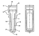
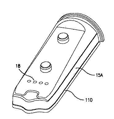
図1を参照するに、ろ過装置10が示され、未ろ過サンプルを受けるサンプルリザーバ11と、図示される如くろ過装置10の側壁上に各々配置した第1膜12A及び第2膜12Bとを含んでいる。デッドストップ容量を画定する保持液チャンバ14が第1膜12A及び第2膜12Bの下方に設けられる。デッドストップ容量をろ過装置の中心軸位置に設けると共に、遠心分離機の方向角が変化するに従うデッドストップの容量変動を実質的に低減させ得る、全体に弧状の且つろ過装置の底部周囲から外側に突出する収集先端30(図2)を設け得る。ろ過装置10は、液体不透性で、タンパク質結合特性が低く且つ遠心分離中の重力(Gs)に耐え得る十分な強度を持つ固形材料製であることが好ましい。好適な材料には、アクリル、CYROLITE G20 HiFlo(商標名)樹脂、ESTAR HN631樹脂、KRATON(商標名)ポリマーが含まれる。特にパネル15A、15B(図3)は、オペレーターまたはユーザーがろ過装置プロセスの前後の液面高さを判定するためにろ過装置の内側キャビティを目視可能な透明プラスチック材料製とし得る。
Referring to FIG. 1, a
ろ過装置10は、パネル15A、15B(図3)に2枚の平シート状の膜を取り付け、次いでこれらパネルをオーバーモールドしてろ過装置のハウジングを形成する。パネル15A(図4)は、膜の支持及び保持液チャンバ14の流体連通性を提供するアンダドレン支持体16を含む。アンダドレン支持体16は、例えば、膜を貫通するろ液を捕捉し、ドレン孔を通して受け用容器に流入させるための、膜下方に位置付けられ長手方向に離間する一連の溝、チャンネル、または表面模様テクスチャを含み得る。側壁15Bも同様に構成される。各膜は、膜通過流体のみが各サイドパネルに位置付けたろ過装置のドレン孔から排出されるよう、各パネル15A及び15Bにシールされる。
In the
ある実施例では、各膜12A及び12Bは各アンダドレン支持体16と同中心を有し且つアンダドレン支持体に対してシールされる。アンダドレン支持体は、膜を支持すると共に膜を可能な限り平坦に維持し、他方、膜下方には流体をろ過装置のドレン孔18を貫いて流動及び通過させ得るに十分な開放空間を生じさせる幾何形状とされる。流体の力学的抵抗は可能な限り小さく維持されることが好ましい。
In one embodiment, each
図11、12、13、14には、円筒状の隆起突出部16(図13)またはパネル後方から突出する多面カラムの如き、アンダドレン支持体の好適な表面模様テクスチャ例が示される。各隆起突出部の頂面は間隔を置いて膜と接触し且つ膜を支持し、かくして遠心分離の旋回運転中の高圧発生時における膜の平面内延伸を最小化する。また表面模様は、膜を支え且つ流体を膜下方に流動させてドレン孔18から排出させ得る。アンダドレン支持体が膜を適正に支持しない幾何形状のものであると、膜の各孔が延びて細長形状化する。孔が細長くなると膜の保持特性が低下する。図11には、一連の不整隆起形状、または隆起突出部16の実施例が示される。図12には、隆起平行四辺形としての隆起突出部16が十字模様を形成する実施例が示される。図14には、やはりアンダドレン支持体を形成するために使用し得る、六角形模様状の隆起突出部16の実施例が示される。これらの模様は例示目的のみのものであり、その他の好適な模様も本発明の範囲内のものとする。
FIGS. 11, 12, 13, and 14 show examples of suitable surface textures of the underdrain support, such as a cylindrical raised protrusion 16 (FIG. 13) or a multi-sided column protruding from the back of the panel. The top surface of each raised protrusion is spaced in contact with and supports the membrane, thus minimizing in-plane stretching of the membrane during high pressure generation during centrifugal swirl operation. The surface pattern can also support the membrane and allow fluid to flow down the membrane and out of the drain holes 18. If the underdrain support is of a geometrical shape that does not properly support the membrane, each hole in the membrane extends and becomes elongated. When the pores are elongated, the retention characteristics of the membrane deteriorate. FIG. 11 shows an example of a series of irregular raised shapes, or raised
好適な膜には微孔質膜や超多孔質膜が含まれる。後者は限外ろ過用に有益である。再生セルロース限外ろ過膜(例えば、マサチューセッツ州ベドフォードのミリポア社より入手可能な“Ultracel Amicon YM”や、“Ultracel PL”膜)は、極端に希釈した、または疎水性サンプル液を対象とするろ過装置用に最適なものである。“タイトな”マイクロ構造を持つ親水性膜を使用すると、タンパク質、DNAその他マクロ分子の、低吸着状況下における良好な保持が促進される。急速分離用のポリエーテルスルフォン限外膜(例えば、やはりミリポア社より入手可能な“Amicon PM”や“Biomax PB”)その他の、“開放”マイクロ構造を有する膜は、血清、血漿、調製組織培養液の如き高濃度サンプル液の濃縮及び脱塩を目的とするろ過装置用に特に好適である。 Suitable membranes include microporous membranes and superporous membranes. The latter is useful for ultrafiltration. Regenerated cellulose ultrafiltration membranes (eg, “Ultracel Amicon YM” or “Ultracel PL” membranes available from Millipore, Bedford, Mass.) Are extremely dilute or filtration devices for hydrophobic sample liquids It is the best one for use. Use of a hydrophilic membrane with a “tight” microstructure promotes good retention of proteins, DNA and other macromolecules under low adsorption conditions. Polyethersulfone ultramembranes for rapid separation (eg “Amicon PM” and “Biomax PB” also available from Millipore) and other membranes with “open” microstructures are serum, plasma, prepared tissue culture It is particularly suitable for a filtration apparatus for the purpose of concentration and desalting of a high concentration sample liquid such as liquid.
各膜12A及び12B(図1)はろ過装置10の長手方向中心線に関して、各膜の頂部が当該長手方向中心線から膜の底部よりも長い距離において離間されるような小角度を付して配向することが好ましい。漏斗状形態が形成される。各膜のこうした位置決めは遠心分離中に接線方向流れを生じさせる上で有益である。角度は約0°以上及び約5°未満、好ましくは約3°が好適であることが分かった。
傾斜させた膜を横に2つ並べた設計例でも、遠心分離中の膜汚損量を低下させる固有の自己清浄化特性が有る。
Each
Even in the design example in which two inclined membranes are arranged side by side, there is an inherent self-cleaning characteristic that reduces the amount of membrane fouling during centrifugation.
傾斜させた膜を横に2つ並べた設計例では、ろ過装置の先端部からろ過装置内にピペット先端を容易に嵌入させてろ過装置の底部に届かせ得る。本ろ過装置のユーザーは代表的には、a)ピペット先端を使用してろ過装置の底部に収集された保持液を所望容量抽出する、または、b)容器または類似のホルダ内でろ過装置を逆旋回させ得る。ろ過装置底部位置の、保持液サンプルを収納する空間は、通常、デッドストップ容量と称される。 In the design example in which two inclined membranes are arranged side by side, the pipette tip can be easily fitted into the filtration device from the tip portion of the filtration device and can reach the bottom of the filtration device. Users of the filtration device typically a) use a pipette tip to extract the desired volume of retentate collected at the bottom of the filtration device, or b) reverse the filtration device in a container or similar holder. Can be swiveled. The space for storing the retentate sample at the bottom position of the filtration device is usually referred to as dead stop capacity.
図3及び図5に示される如く、各パネル15A及び15Bは、保持液チャンバ14と流体連通し且つろ液をろ過装置のハウジング10を貫通させ、受け用容器75(図7)の如き別のハウジングに収集させる1つ以上のドレン孔18を含む。図示した実施例ではそうしたドレン孔が2つの各パネルに例示されるが、本発明は図示した実施例に限定されるものではない。各ドレン孔18を各アンダドレン支持体の溝またはチャンネルの底部に位置付けることが好ましく、ドレン孔の断面は実質的に円形であることが好ましい。ドレン孔は、ろ過装置製造中に使用され得るヒートシール操作中に収縮されまたはそうでなければ有害な変化を生じないよう、各パネル15A及び15Bの側縁部から十分な距離離間させて位置付けるべきである。ドレン孔18は相互に等間隔を有し且つ共直線上に配置されることが好ましい。
As shown in FIGS. 3 and 5, each
各パネル15A及び15Bは同一でしかも相互弾発嵌合または相互押し嵌め形態を有することが好ましい。ラビリンスシールを使用して各パネルを相互にシールすることが好ましい。ラビリンスシール例は溝内リブ形態のものであり、その場合、各パネルはその各内縁部の一方に沿って形成した溝19と、他方に沿って形成したリブ20(図4)とを含む。溝19及びリブ20は、パネル15Aをパネル15Bと整列状態に持ち来すとパネル15Aのリブ20がパネル15Bの溝19と係合し、同様に、パネル15Bのリブ20がパネル15Aの溝19と係合する如き形態とされる。このラビリンス形態により、各パネルの、オーバーモールドプロセスに先立ち且つオーバーモールドプロセス全体を通しての対称整列化が助成され、かくして、自動組み立てが容易化され、組み立てプロセスのマシン故障耐性が向上する。ラビリンス整列は、サンプル容量中へのオーバーモールド材料の進入を防止する塑性流動トラップとしても機能する。溝19は深い凹所を持つ1つ以上の部分を含み得、各深い凹所は溝の相当する高い突出部を受け、かくして2枚のパネル同士の弾発嵌合を容易化する。間隔を置いた一連のウェルと合致する、間隔を置いた一連の突起の如き、弾発嵌合または押し嵌め用のその他設計例及びシールは本発明の範囲内のものとする。
The
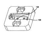
整合ピン86及び87(図3)が各パネルの外側表面に一体成形される。整合ピン86及び87は、膜装着中及び自動ピックアンドプレース操作中にろ過装置を保持するために使用するネストフィクスチャ内の整列穴に各パネルを精密に整合させ得る。自動プロセスを使用して各パネルを膜装着モジュール、膜整合モジュール、オーバーモジュール、プロセス内品質検査モジュール、内に移動させ得る。整合ピンの1つは、各パネルをネスト108(図27)内で然るべく固定し、他方、第2の整合ピン87はプロセス処理中に生じ得る熱膨張によるパネルの1方向成長を許容するよう設計される。各整合ピンは、オペレーターが水またはクリーニング溶剤で濡れたラストマー製手袋でも楽に保持できる指把持特徴構造部をも提供する。突出する整合ピンは、ユーザーによるろ過装置の誤滑落を防止する上でも役立つ。
Alignment pins 86 and 87 (FIG. 3) are integrally formed on the outer surface of each panel. Alignment pins 86 and 87 can precisely align each panel with an alignment hole in the nest fixture used to hold the filtration device during membrane loading and automatic pick and place operations. An automated process may be used to move each panel into the membrane loading module, membrane alignment module, overmodule, in-process quality inspection module. One of the alignment pins secures each panel accordingly in nest 108 (FIG. 27), while the
図3にはろ過装置10におけるオーバーモールドプロセス状況が示される。パネル15A及び15Bは、オーバーモールドジャケットを各パネルに機械的に捕捉させる上部成形フランジ17及び側方フランジ110をも含み得る。上部成形フランジ17及び側方フランジ110は、各パネルをオーバーモールドジャケットに固定し、かくして、一体且つ丈夫なろ過装置を形成するために使用するアンカーを形成する。これにより、フープ応力破壊やろ過装置バースト圧力耐性が改善される。実際、前記ろ過装置は、有効運転上必要とされるそれよりも206842.7〜551580.55Pa(30〜80psi)高い、約1723689.25Pa(約250psi)(図18)以上の高い圧力耐性を示した。各パネルはオーバーモールド材料のそれよりも溶融温度の高いポリマーから作製される。それらの材料には、ポリスチレン、アクリル、スチレン、ブタジエンコポリマー、スチレンアクリロニトリル、CYROLITE G20 HiFlo(商標名)樹脂、ESTAR HN631(商標名)樹脂、KRATON(商標名)ポリマー、が含まれ得る。これらの材料により、オーバーモールドプロセスが安定化され、前成形材料への熱伝導による前成形部品の熱変形が生じない。前成形部品が熱変形するとろ過装置全体の形態、嵌合性、機能が低下する。
FIG. 3 shows the overmold process status in the
オーバーモールドジャケット111(図3)は、遠心分離中に容器の壁断面を円形に保つ一体の幅広フランジ88を含み得る。オーバーモールドジャケット(以下、単にジャケットとも称する)は、熱可塑性プラスチック材を熱溶融させ、パネルの上部成形フランジ17及び側方フランジ110を相互に機械的に錠止させることにより2枚のパネルを相互取り付けする。ジャケットは、ジャケットの、ろ過装置に流体を追加する頂部89(図1)にして、遠心分離機の旋回中の如きにおいてろ過装置を閉じるための容器キャップ80(図7及び8)を使用する頂部89位置から開始される。ジャケットの内径(図1)は、コアピンの1つ102(図26)の周囲に連続態様下に形成される。当該コアピンにより、キャップシール81(図7及び8)の形状は受容可能状態に確実に制御される。ろ過装置の長手方向軸に沿って外側表面91(図1)上に分割線が形成されるが、当該分割線は、“分割線不整合”を防止するために、内径部分に沿っては使用されない。分割線不整合は、通常は各型を2つの半分体に開く設計とした場合に生じる。オーバーモールドジャケットの内径部に分割線を形成しないことにより、キャップとろ過装置との間に望ましからざる間隙が生じないことが保証される。そうした間隙が存在しないことで、流体シールの形態、嵌合及び機能が、ジャケット及び容器キャップ位置で受け入れ可能なものであることが保証される。
The overmolded jacket 111 (FIG. 3) may include an integral
ジャケットには、ジャケット(図2)の上部112から底縁部113まで同直径に維持されるオーバーモールド材料部分が含まれる。ジャケットの底縁部には、受け用容器の内径部85(図7)と機械的に接触してジャケットを該受け用容器内で保持する一体の幅広フランジ88(図3)が含まれる。この特徴により、ろ過装置により生じる負荷または応力が受け用容器の肩部に分散され、かくして遠心分離機内での高速旋回運転が容易化される。
The jacket includes a portion of the overmold material that remains the same diameter from the top 112 to the
図23及び24には、ジャケットの全体形状に比較した、一体の幅広フランジ88の相対比率が示される。幅広フランジ88(図24)の幅(例えば約6.4mm(約0.250インチ))は、側方から見た場合、2枚のパネルを融合させて1つのろ過装置としたオーバーモールドジャケットのシールの幅115(例えば約3.7mm(約0.144インチ))よりも広い。幅広フランジ88は、応力が適切に分散され且つ受け用容器の内径部85(図7)に伝達されることを保証するために、ジャケットの外径116(図24)の少なくとも65%である必要がある。ドレン孔18からろ液を排出させるために十分な空間117(図25)が必要とされることから、幅広フランジ88の幅はジャケットの外径の少なくとも80%以上とすべきではない。
23 and 24 show the relative proportions of the integral
幅広フランジ88の移行部118(図25)が、オーバーモールドジャケットのシール119の、ろ過装置の直径の半分に略等しい位置から開始される。ジャケットの前記シールからの移行部の曲線は応力集中を最小化するよう意図的に緩くされる。幅広フランジ88の外径は、ジャケットの上部リム位置の外径と同じである。これにより、ろ過装置を図9に示す如く同じ受け用容器内で反転させた状態で旋回させ得る。
The transition 118 (FIG. 25) of the
幅広フランジ88は、10,000Gに等しい、またはそれ以上であり得る遠心分離機旋回負荷運転中に、ろ過装置を然るべく保持するために十分な材料的支持を提供する。実験によれば、幅広フランジにより、ろ過装置を16,000Gの如き高い遠心旋回負荷の下で損傷させることなく1時間旋回させ得ることが示された。幅広フランジを用いない場合、幾つかのろ過装置は塑性変形し、受け用容器の底部内に崩壊した。崩壊したろ過装置を分析した結果、幅広フランジは受け用容器の壁を可能な限り円形に維持し、また、ろ過装置と、受け用容器の支持用リム、即ち内径部85との間の接触応力を、当該受け用容器の塑性降伏応力以下に分散させる上で必要であったことが分かった。
The
ジャケットの頂部89(図1)位置におけるジャケット壁は、遠心分離旋回プロセス中に容器キャップ80の発生する応力による分割破断を防止するに十分な厚さとする必要がある。好適な厚さは約0.1mm(0.004インチ)である。容器キャップ80をろ過装置上に押し嵌めして液体シールを確立するとフープ応力が生じる。ろ過装置を遠心分離機内で16,000Gあるいはそれ以上が発生する速度下に旋回させると、弾発嵌合特徴部と組み合わせた容器キャップの質量によりろ過装置内に引張フープ応力が生じる。当該応力が十分大きいとろ過装置の側壁がニットラインに沿って破断する。ニットラインは、オーバーモールドプロセス中に2つ以上のプラスチック溶融流れが合致して相互に溶融する連結部に対して参照される。
The jacket wall at the position of the top 89 of the jacket (FIG. 1) needs to be thick enough to prevent split breakage due to stress generated by the
ジャケット111(図3)は、異なる着色添加剤を使用して作製し得、これにより、異なるろ過装置形態の色による差別化が可能となる。
ろ過装置が破損しないことを保証するために、ジャケット壁は、a)所望されざるキャップ開放を招く弾性変形、b)同様に所望されざるサンプル流体の漏出を招く塑性変形及び破壊、を防止するに十分な厚さとすべきである。タンパク質結合性の低い材料としてスチレンブタジエンコポリマーを選択する場合、壁厚を少なくとも約0.9mm(0.035インチ)とするのが好適であることが分かった。
The jacket 111 (FIG. 3) can be made using different color additives, which allows differentiation by the color of different filtration device configurations.
In order to ensure that the filtration device does not break, the jacket wall prevents a) elastic deformation that leads to undesired cap opening, and b) plastic deformation and breakage that also causes undesired leakage of sample fluid. It should be thick enough. When selecting a styrene butadiene copolymer as the low protein binding material, it has been found that a wall thickness of at least about 0.9 mm (0.035 inches) is preferred.
ジャケットの頂部89(図1)位置のジャケット壁厚を増大すると、ろ過装置の内容積(図1)が所望されざる水準に低下する。当該内容積が0.45μl未満のものは商業的に望ましくない。内容積が0.5μlであるろ過装置が、望ましく且つ商業的に戦略的価値を有すると考えられる。 Increasing the jacket wall thickness at the top 89 of the jacket (FIG. 1) reduces the internal volume of the filtration device (FIG. 1) to an undesired level. Those with an internal volume of less than 0.45 μl are not commercially desirable. A filtration device with an internal volume of 0.5 μl is considered desirable and commercially strategically valuable.
あるテストケースにおいて、型ベース温度を約32.2〜51.7℃(90〜125°F)のに上昇するとニットラインはずっと有効に相互溶融し、強度が増大した。使用する任意の追加的な熱が、各パネルの底部を溶融及び崩壊させる原因とならないことが保証されるように十分注意する必要がある。 In one test case, increasing the mold base temperature to about 32.2-51.7 ° C. (90-125 ° F.) resulted in much more effective mutual melting of the knit lines and increased strength. Care must be taken to ensure that any additional heat used does not cause the bottom of each panel to melt and collapse.
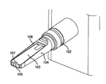
ろ過装置の2枚のパネルは、各パネルのノーズ位置及び各パネルの中心位置での全体圧力を指示するに十分厚く且つ堅固である必要がある。最新の幾何形状及びスチレンブタジエン材料を使用した実験によれば、受け入れがたい変形及び崩壊を防止するには少なくとも約1.5mm(0.0585インチ)の壁厚が必要であることが分かった。この壁厚及び好適な壁強度は、各パネルをろ過装置として完成させるオーバーモールドプロセス中にパネルをスチール製のコアピン102(図26)で支持した場合でさえ必要であった。膜表面に最も近いピンの表面103は、膜がコアピン102(図26)と接触しないことが保証されるよう除去された。膜の保持層は、膜がコアピンと接触すると破壊され得、オーバーモールド型キャビティから部品を取り出す際に擦傷を受け得る。
The two panels of the filtration device need to be thick and rigid enough to indicate the total pressure at the nose position of each panel and the central position of each panel. Experiments using modern geometries and styrene butadiene materials have shown that a wall thickness of at least about 1.5 mm (0.0585 inches) is required to prevent unacceptable deformation and collapse. This wall thickness and suitable wall strength was necessary even when the panels were supported by steel core pins 102 (FIG. 26) during the overmolding process that completed each panel as a filtration device. The
膜がパネルから引き離されてコアピン102の表面による擦傷を受けないよう、コアピンには、オーバーモールド型キャビティの空気をコアピンの中心を通って排気させ得る通気口104を形成する。この独特のコアピン形態により、装着した膜を過剰に加圧して膜をパネルから吹き外さない様式下での、ろ過装置のオーバーモールドが可能となる。
To prevent the membrane from being pulled away from the panel and being scratched by the surface of the
オーバーモールド型キャビティのポートの冷却設計に対しては特に注意を払う必要がある。幾つかの実験に際し、オーバーモールド材料の、ベースモールドでは約32.2℃(90°F)であった温度が約19.5度(35°F)上昇して約51.7℃(125°F)になっただけで、追加の熱がパネル内に流入し、パネルが溶解し始め、コアピン上に崩壊したことが観察された。ある場合には、熱の影響は、各パネルをオーバーモールド型キャビティから僅かに浮かせ、かくして漏出したプラスチックをパネルの外壁を覆って流動させるに十分なものであった。ある場合には、プラスチックの漏出はろ過装置が尚、良好な品質を保つに十分小さいものであった。最悪の場合では、流動するプラスチックが上方のドレン孔にまで達してドレン孔を部分的に充填した。これは、ドレン孔を貫く流れを制限するので望ましくないと考えられる。 Special attention must be paid to the cooling design of the overmolded cavity port. During some experiments, the temperature of the overmold material, which was about 32.2 ° C. (90 ° F.) in the base mold, increased by about 19.5 ° C. (35 ° F.) to about 51.7 ° C. (125 ° C.). Only by becoming F) it was observed that additional heat flowed into the panel, the panel began to melt and collapsed onto the core pins. In some cases, the thermal effect was sufficient to cause each panel to float slightly from the overmolded cavity, thus allowing the leaked plastic to flow over the outer wall of the panel. In some cases, the plastic leakage was small enough for the filtration device to still maintain good quality. In the worst case, the flowing plastic reached the upper drain hole and partially filled the drain hole. This is considered undesirable because it restricts the flow through the drain hole.
前成形パネルにおける熱の悪影響は、オーバーモールド型キャビティ及びコアピンの熱的冷却を改善し、且つ、プラスチック射出ポート92(図1及び23)位置に、狭幅の縁部ゲートに代えて弁ゲートを使用することにより解決され得る。狭幅の縁部ゲートは熱を更に発生する高レベルの剪断流れをプラスチックに創出させる。この剪断流れはもっと流れ断面積の大きい弁ゲートを使用することで低減させ得る。大きな流れ断面積により、剪断熱の悪影響が減少され、かくしてオーバーモールド型キャビティの充填がずっと容易化され得る。 The adverse effect of heat on the pre-formed panel improves the thermal cooling of the overmolded cavities and core pins, and a valve gate instead of a narrow edge gate at the plastic injection port 92 (FIGS. 1 and 23). It can be solved by using. The narrow edge gate creates a high level of shear flow in the plastic that further generates heat. This shear flow can be reduced by using a valve gate with a larger flow cross section. A large flow cross-sectional area can reduce the adverse effects of shear heat and thus make the filling of overmold cavities much easier.
弁ゲートは射出成形において、オーバーモールド型キャビティ内にホットランナーからの溶融プラスチックポリマーの流れを送るために使用される。成形結果を最良化するためには、当該ポリマーの流れを、オーバーモールド型キャビティ内のコアピン95(図10)及び105(図26)の如き固体表面に向けて送るべきである。この流れは、仕上げ品の表面を粗化させる材料の流跡やジェッティングを防止するために、分散及び乱流状態で旋回させる必要がある。 The valve gate is used in injection molding to send a flow of molten plastic polymer from the hot runner into the overmold cavity. In order to optimize the molding results, the polymer stream should be directed towards a solid surface such as core pins 95 (FIG. 10) and 105 (FIG. 26) in the overmolded cavity. This flow must be swirled in a dispersed and turbulent state to prevent material traces and jetting that roughen the surface of the finished product.
オーバーモールドにおける熱の悪影響は、冷却ラインを製品表面に接近して配置すること及び、コアピン内の熱冷却ラインを増大させることによっても解決され得る。これは、通常は水またはポリプロピレングリコール溶液の如き代表的な冷却流体を使用することで達成され得る。
熱の悪影響は、熱伝導度のずっと高い型インサートを使用することによっても解決され得る。高熱伝導度材料は、低熱伝導度材料を使用する場合よりもずっと効率的に各製品を除熱し得る。そうしたインサートは通常はオーバーモールド型キャビティ内に締着され、スチールの1種を使用する場合よりもずっと効率的に、前成形品からの伝熱を助成する。代表的なインサートは、ベリリウム、銅、アルミニュームの如き金属を使用して作製し得る。
The adverse effects of heat in the overmold can also be solved by placing the cooling line close to the product surface and increasing the thermal cooling line in the core pin. This can usually be achieved by using a typical cooling fluid such as water or a polypropylene glycol solution.
The adverse effects of heat can also be solved by using mold inserts with much higher thermal conductivity. High thermal conductivity materials can remove heat from each product much more efficiently than when low thermal conductivity materials are used. Such inserts are usually clamped in overmolded cavities and assist in heat transfer from the preforms much more efficiently than using one type of steel. Typical inserts can be made using metals such as beryllium, copper, and aluminum.
図10にはパネルのノーズ部内に生じ得る漏出を、シールとして作用する突出部93をパネルの外側表面上に追加することにより解決する状況が示される。このシール特徴部はパネルの外側表面中に一体成形され、機械的なO−リングシールと同様に機能し得る。オーバーモールド型キャビティをパネルを覆う状態で閉じると、オーバーモールド型キャビティ壁は一体成形したシール特徴部と密着する。当該シール特徴部はろ過装置のドレン孔18内へのプラスチック漏出を防止する。
FIG. 10 shows a situation in which leakage that may occur in the nose portion of the panel is solved by adding a
コアピン102(図26)は硬質スチール材から作製することが好ましい。ロックウェル硬さ32〜34RcのP20スチールで作製したコアピンは、小数のろ過装置を満足裡に製造するに十分であり得るが、当該コアピンは結局は変形され得、ろ過装置の、ハウジング破壊圧力で測定されるところのハウジング破壊強度を損なわせる。従って、コアピン材料は、耐性が更に大きい、ロックウェル硬さ53〜54RcのH13スチールであることが好ましい。かくして、材料硬さと、コアピンの設計形状とは、商業スケールでろ過装置を成功裏に製造するためには注意深く制御する必要がある。 The core pin 102 (FIG. 26) is preferably made from a hard steel material. A core pin made of Rockwell hardness 32-34 Rc P20 steel may be sufficient to produce a small number of filtration devices satisfactorily, but the core pin may eventually be deformed and at the housing breaking pressure of the filtration device Damage to the housing breaking strength as measured. Therefore, the core pin material is preferably H13 steel having a Rockwell hardness of 53 to 54 Rc, which is further resistant. Thus, the material hardness and the design shape of the core pin need to be carefully controlled in order to successfully manufacture a filtration device on a commercial scale.
オーバーモールドプロセスにおいてろ過装置を確実に良好に製造する上で、以下の要因を制御することも極めて重要である。
A.コアピンを、コアピンの表面103(図26)が膜の保持表面と接触して当該表面を損傷させないようパネルをしっかりと保持する設計及び形状とすること。
Control of the following factors is also extremely important for reliably and successfully manufacturing the filtration device in the overmold process.
A. The core pin is designed and shaped to hold the panel firmly so that the core pin surface 103 (FIG. 26) does not come into contact with and damage the holding surface of the membrane.
B.コアピン用材料を、連続的な成形運転中における適切冷却が保証される設計、形状とし且つ選択すること。冷却が不適切であるとパネルが熱変形する。
C.コアピン用材料を、連続的な成形運転中に所望されざる変形が生じないことも保証される設計、形状とし且つ選択すること。コアピンの設計形状に、全体形状を補強し且つ横断方向への変形を低減させる支持グリップ106を含ませることにより、剛性化が成功裏に達成された。コアピン102の端部105は、パネルのノーズ部をオーバーモールド型キャビティ内に押し込んで各パネルをオーバーモールド型キャビティ96内に適正座着させ、オーバーモールド中に各パネルが射出弁ゲート97から押し出されないようにするに十分な強さ及び十分な剛性を有すべきである。
B. The core pin material should be designed, shaped and selected to ensure proper cooling during continuous molding operations. If the cooling is improper, the panel will be thermally deformed.
C. The core pin material is designed, shaped and selected to ensure that undesired deformation does not occur during continuous molding operations. Stiffening has been successfully achieved by including a
D.前成形した各パネルの支持用の整合ピンと、オーバーモールドしたパネルの凹所99との間の逃げ98(図10)は最小化されるべきである。これは、オーバーモールド工程中に各パネルを射出弁ゲートから離動させないために必要である。
E.前成形した各パネルと、オーバーモールド型キャビティとの間の逃げ間隙100(図10)を注意深く制御し且つ最小に維持することにより、各パネルの外壁に沿ったオーバーモールド材料の所望されざる漏出を防止すること。
D. The clearance 98 (FIG. 10) between the pre-formed panel support alignment pin and the
E. Carefully controlling and keeping the clearance gap 100 (FIG. 10) between each pre-formed panel and the overmold cavity to minimize unwanted leakage of the overmold material along the outer wall of each panel. To prevent.
F.各パネルと、オーバーモールド型キャビティとの間のシール界面の寸法形状を、良好なシャットオフ品質が保証されるよう極めて注意深く制御することにより、ドレン孔18(図3)及び膜12A及び12B(図1)内へのプラスチック漏出を防止すること。
G.オーバーモールドに際して使用するプロセスパラメータを調節することにより、各パネルとオーバーモールド型キャビティとの間のシール界面を横断しての、ポリマー材料の所望されざる漏出を防止する上での改善を徐々に提供させ得る。これらのプロセスパラメーターは、a)成形中の樹脂停止温度、b)型ベースの温度、c)成形中の背圧使用、から成る。しかしながら、これらのプロセスパラメータの調節は、各パネルとオーバーモールド型キャビティとの間のシール界面の適正な寸法付けに対する代替法とはならない。
F. By very carefully controlling the size and shape of the seal interface between each panel and the overmolded cavity to ensure good shutoff quality, drain holes 18 (FIG. 3) and
G. Adjusting the process parameters used during overmolding provides gradual improvements in preventing unwanted leakage of polymer material across the seal interface between each panel and the overmold cavity Can be. These process parameters consist of a) resin stop temperature during molding, b) mold base temperature, and c) back pressure usage during molding. However, adjusting these process parameters is not an alternative to proper dimensioning of the seal interface between each panel and the overmolded cavity.
H.コアピンを、コアピン102の表面103(図26)と、パネルに取り付けた膜12A及び12B(図1)との間に、オーバーモールドプロセス中に前記表面と膜とが接触しない十分な逃げを保証するべき寸法及び形状とすること。そうした接触はろ過装置の全体性能を損なわせ得る深刻な損傷を膜の保持層に生じさせ得る。
I.コアピンを、コアピン102の先端105位置に、各パネルの先端内に一体成形したドーム特徴部25(図1及び6)を支持するに十分な逃げをも保証するべき寸法形状とすること。
H. The core pin ensures sufficient clearance between the
I. The core pin should be sized and shaped to ensure sufficient clearance to support the dome feature 25 (FIGS. 1 and 6) integrally molded within the tip of each panel at the location of the
パネルを良好に前成形するために、各パネルの、ドレン孔付近でノーズ92(図23)位置に射出成形の弁ゲートを位置決めし、ろ過装置全体の構造的一体性を確実に最良化させる必要がある。パネルのノーズ位置に弁ゲートを配置することによりプラスチック材料が型内に流入し、アンダドレン支持体構造内に、膜装着領域を横断しない材料のニットラインが優先的に位置決めされる。ニットラインが膜装着領域に形成されると、ろ過装置の保持性能が損なわれる。膜材料を装着する際の加熱プロセスにより、ニットラインは所望されざる様式下に開放され、かくして流体がシール周囲に漏出する。 In order to pre-form the panels well, it is necessary to position the injection molded valve gate at the nose 92 (Fig. 23) position near the drain hole of each panel to ensure the best structural integrity of the entire filtration device. There is. Placing the valve gate at the nose position of the panel causes the plastic material to flow into the mold and preferentially positions a knit line of material that does not cross the membrane mounting area within the underdrain support structure. When the knit line is formed in the membrane mounting region, the holding performance of the filtration device is impaired. The heating process in loading the membrane material opens the knit line in an undesired manner, thus leaking fluid around the seal.
膜片は、必要とされる膜片間寸法精度を実現する合致ダイセットを使用して自動ダイカットされる。膜片の自動ダイカット、装着、シール、のプロセスはこれらろ過装置の製造上極めて重要である。自動製造プロセスにより、膜片の保持層に生じ得る表面損傷が低減される。自動プロセスは、これらのろ過装置を手作りするプロセスに比較してその労力を低減させる。自動製造プロセス使用時には、オペレータ間変動による悪影響もまた低減される。 The membrane pieces are automatically die cut using a matching die set that achieves the required dimensional accuracy between the membrane pieces. The process of automatic die-cutting, mounting and sealing of membrane pieces is extremely important for the production of these filtration devices. The automated manufacturing process reduces surface damage that can occur in the retaining layer of the membrane pieces. The automated process reduces its labor compared to the process of making these filtration devices by hand. When using automated manufacturing processes, adverse effects due to inter-operator variation are also reduced.
特にろ過装置の頂部89(図1)は、ろ過装置における連続リムを形成するよう設計するべきである。ろ過装置の内径90は、1つのコアピン102(図26)上に形成する必要がある。これにより、円滑で且つ一貫した1つのシール表面が確実に形成され、これが、ろ過装置と容器キャップとの間における良質なシール形成を保証する。オーバーモールド成形では割り型使用が設計条件となることから、型半分体に関する分割ラインをプラスチックのニットラインから90°離して位置決めする必要がある。この設計によれば残留成形応力、ニットライン、及び分割ラインの整列が防止される。この特徴により、ろ過装置は遠心分離旋回中のずっと高い応力に耐え得る。応力耐性が高まることで、旋回速度を一層高め得、ろ過装置時間を更に短縮させることが可能である。これらの特徴の組み合わせにより、顧客に“他では得られない価値“が提供される。
In particular, the top 89 of the filtration device (FIG. 1) should be designed to form a continuous rim in the filtration device. The
ラビリンスシール特徴部、即ち溝19及びリブ20(図4)は、a)組み立て中の2枚のパネル15A及び15B(図3)の整列を容易化し、b)オーバーモールド中のプラスチック進入を制御及び防止するべく、各パネルの縁部内に設計上特別に組み込まれる。上述した如く、例示したラビリンスシール特徴部は、パネルの中心線の一方側における凸状のリブ20(図4)と、前記中心線の他方側における同一の凹状の溝19とを含む。当該ラビリンスシール特徴部は、各サイドパネルの中心軸を中心する対称形状であることが好ましく、それにより、組み合わせて1つのろ過装置とする2枚のサイドパネルを一つのオーバーモールド型キャビティで作製可能となる。これにより、同じ組み合わせを別個の2つの型を用いる場合よりもコストが削減され得る。ラビリンスシール特徴部は、組み合わせた2枚の各パネルの形成する内容積と、各パネルを包囲する外側空間との間に蛇行通路をも創出する。蛇行通路は、オーバーモールド型キャビティを閉じた時に各パネル縁部を封止させ、オーバーモールドプラスチック材を流動させて2枚のパネルを相互にシールさせる上で役立つ。蛇行通路は、ろ過装置内へのオーバーモールドプラスチック材の流入を防止する。
Labyrinth seal features, i.e.,
各パネルにおけるドレン孔18の形状及び位置は、特に、デッドストップ容量、受け入れ可能な流体量、受け入れ可能な型耐性、における変動を低減させるよう設計される。ドレン孔形成に使用するコアピンは、各側部に5°の抜き勾配を持つ設計とされる。当該抜き勾配によりコアピン強度が向上され、各コアピンを、成形した各パネルから容易に分離させることが可能となる。抜き勾配は勾配穴をも創出し、当該勾配穴の大きく開放した側部が各パネルの内側部分に配置される。ドレン孔は尚、その横断面が実質的に円形である。ドレン孔は、流体が放出表面に向けて外側に移動してろ過装置から出る方向に徐々に狭くなる。勾配穴は、ドレン孔を通過する流体流れを縮流効果を利用して改善させる。 The shape and location of the drain holes 18 in each panel are specifically designed to reduce variations in deadstop capacity, acceptable fluid volume, acceptable mold tolerance. The core pin used for drain hole formation is designed to have a draft angle of 5 ° on each side. The draft angle improves the core pin strength, and each core pin can be easily separated from each molded panel. The draft angle also creates a gradient hole, and the wide open side of the gradient hole is located in the inner part of each panel. The drain hole is still substantially circular in cross section. The drain holes gradually narrow in the direction in which the fluid moves outward toward the discharge surface and exits the filtration device. The gradient hole improves the fluid flow passing through the drain hole by utilizing the contraction effect.
縮流効果は、ベルヌーイの定理において、流体流れの断面積はニュートン流体がオリフィスを通過するに従い狭幅化または狭窄化されると予測されるところの、オリフィスを通過する層流に関して説明されるものである。流体流れは、勾配穴の表面が流体流れのストリームラインを追随する場合に効率化される。流れの分離頻度が低下し、かくして循環流体流れの発生が低減される。流体の再循環流れが低減されることで、流体流れ中の、フォーム形成の原因となり得る同伴気泡の形成量が低減され得る。受け用容器内のろ液中にフォームが形成されると、遠心分離を停止させた場合に流体が吸引されてジャケットに戻る原因となり得ることから望ましくない。 Constriction effects are explained in Bernoulli's theorem for laminar flow through an orifice where the fluid flow cross-sectional area is expected to narrow or narrow as Newtonian fluid passes through the orifice It is. Fluid flow is streamlined when the surface of the gradient hole follows the fluid flow stream line. The frequency of flow separation is reduced, thus reducing the generation of circulating fluid flow. Reducing the fluid recirculation flow can reduce the amount of entrained bubble formation in the fluid flow that can cause foam formation. Formation of foam in the filtrate in the receiving container is undesirable because it can cause fluid to be sucked back into the jacket when centrifugation is stopped.
保持液チャンバ14(図4)は、保持液サンプルを収集及び回収し得るデッドストップ容量を画定する。保持液チャンバは、デッドストップ容量をろ過装置の中心線位置に位置付けると共に、遠心分離機の角度方向変化に伴うデッドストップ容量変動を減少させるべく、内壁から突出するマウンド形突出部またはドーム特徴部25(例えば図4及び6)の如き3次元的な不連続部を含むことが好ましい。詳しくは、ろ過装置底部位置の漏斗形態と、前記不連続部とにより、保持液はデッドストップ容量の底部位置のもっと小さい空間内に配置される。流体をそうした小空間内に配置することで、ピペットを使用してろ過装置から流体をより完全に除去する操作が容易化される。ろ過装置に当該構造が無い場合はユーザーはデッドストップ容量の底部でピペットを横断方向に1回以上前後移動させなければならない。更に、漏斗形態及び不連続部とにより、遠心分離機内でろ過装置の角度方向が変化した場合のデッドストップ容量変動も低減される。
The retentate chamber 14 (FIG. 4) defines a dead stop volume that can collect and collect a retentate sample. The retentate chamber positions the deadstop volume at the centerline position of the filtration device and mound-shaped protrusion or
マウンド形突出部25の如き不連続部の高さ及び形状は以下の如く決定される。ろ過装置を受け用チューブ内に配置し、自由度2を成す異なる方向に向ける。自由度2の一方では、ろ過装置の中心軸が、遠心分離機で使用する固定アングルローターの方向と整列する。固定アングルは代表的には垂直から35〜45°の間である。試行錯誤を経た上で、デッドストップ容量変動が最小となる不連続部の最適高さ及び形状を決定する。
The height and shape of the discontinuity such as the mound-shaped
自由度2の他方では、ろ過装置が受け用容器内で且つ固定アングルロータ内に配置される。当該状況下においてろ過装置は尚、その中心軸上で1〜360°の間の無限角度位置で回転される。従って、最極を成す2方向として、a)2つの膜平面が可能な限り垂直方向に位置決めされる前方向と、b)2つの膜平面が、代表的には35〜45°の間であり得るローター角に可能な限り接近して位置決めされる側方向と、を選択する。再度の試行錯誤を経た上で、デッドストップ容量の変動を最小化させる突出部の高さ及び形状を決定する。ドーム特徴部25の好適高さは約0.5mm(0.020インチ)である。
On the other of the two degrees of freedom, the filtration device is arranged in the receiving container and in a fixed angle rotor. Under such circumstances, the filtration device is still rotated at an infinite angular position between 1 and 360 ° on its central axis. Thus, the two most polar directions are: a) a forward direction in which the two membrane planes are positioned as vertically as possible, and b) the two membrane planes are typically between 35 and 45 degrees. Select the side direction that is positioned as close as possible to the resulting rotor angle. After going through trial and error again, the height and shape of the protrusion that minimizes the variation in dead-stop capacity are determined. The preferred height of the
表2には本発明に従う各実施例の遠心分離ろ過装置と、従来のミリポア社製の商標名Microconろ過装置との性能比較試験結果が要約される。当該試験に際しては、異なる2つの膜形態、即ち、30kDa膜と、50kDa膜とが考慮された。結果によると、有効膜面積が増大されていることから予測された如く、本発明のろ過装置では商標名Microconろ過装置におけるよりもずっと早く水がろ過されたことが示された。プロットによれば、商標名Microconろ過装置では、水ろ過装置はフィルタ上流側に水が残留しない乾燥状況となるまで継続されたことが示される。本発明のろ過装置では水は設計上のデッドストップ容量が達成されるまで継続ろ過された。これらのデータは、本発明のろ過装置が、サンプル回収が損なわれ得る乾燥状況までろ過される心配無く、所定のデッドストップ容量までサンプルのろ過及び濃縮に使用され得ることを実証している。 Table 2 summarizes the results of performance comparison tests between the centrifugal filtration device of each example according to the present invention and a conventional Microcon filtration device manufactured by Millipore. In the test, two different film forms were considered: a 30 kDa film and a 50 kDa film. The results showed that water was filtered much faster in the filtration device of the present invention than in the trade name Microcon filtration device, as predicted by the increased effective membrane area. The plot shows that in the trade name Microcon filtration device, the water filtration device was continued until it reached a dry condition where no water remained on the upstream side of the filter. In the filtration device of the present invention, water was continuously filtered until the design dead-stop capacity was achieved. These data demonstrate that the filtration device of the present invention can be used for filtering and concentrating samples to a predetermined deadstop volume without worrying about being filtered to dry conditions where sample recovery can be compromised.
ある実施例では、保持液は逆旋回運転を使用して回収される。その場合、ろ過装置10(図9)は、反転させた状態でビンその他好適なハウジングの如き受け用容器75内に配置されて遠心力の如き駆動力を受け、保持液が保持液チャンバ14から受け用容器75に強制流入される。図9に最もよく示されるように、受け用容器75は、前方旋回モード(図8)及び逆旋回モード(図9)の何れにおいてもろ過装置10を収受するに十分な幅の直径の円筒状断面を有することが好ましい。受け用容器75は、好ましくは環状の肩部85を含み得、当該肩部が受け用容器75内へのろ過装置の挿通量を制限する(旋回モードまたは逆旋回モードの何れでも)ストッパを提供するための、受け用容器75内の小内径部分を形成する。かくして、図8の旋回モードではろ過装置10の上方フランジ76は受け用容器75の外側に残り、図9の逆旋回モードではろ過装置10の底部が図示される如く受け用容器75の外側に残る。ろ過装置10を受け用容器75内にこのように位置決めした場合、ろ過装置10の下方には、逆旋回運転中に得られる十分な液体製品を受ける十分な容量77が残されるべきである。
In certain embodiments, the retentate is collected using a reverse swirl operation. In that case, the filtration device 10 (FIG. 9) is placed in a receiving
容器内の肩部の設計及び形状はろ過装置の形状的フィット性及び機能上極めて重要である。遠心分離における最大負荷レベルは、円周方向に連続する設計構成のリング85を使用する場合に達成され得る。肩部を不連続的な設計構成とした場合は遠心分離負荷レベルがずっと低下し得る。遠心分離負荷が低レベルであると、遠心分離機内でろ過装置操作をより高速で実施する能力が低下する。
The design and shape of the shoulder in the container is extremely important for the shape fit and function of the filtration device. The maximum load level in centrifugation can be achieved when using a circumferentially designed
ホルダまたは受け用容器は、当該受け用受け用容器75に図示の如く一体取り付けし得るキャップ80を含むことが好ましい。キャップは、ろ過装置10がジャケット内に位置決めされない場合に該受け用受け用容器75を、そしてろ過装置10が図8に示す如く旋回モード下にろ過装置内に位置決めされる場合はろ過装置10を、キャップ閉めするべく寸法付けされる。この目的上、キャップ80は、その外径がろ過装置上部及びろ過装置上部の何れの内径よりも若干小さい第1の小円筒状部分81と、当該第1の小円筒状部分81の外径よりも大きい外径の第2の大円筒状部分82とを含み得る。第2の大円筒状部分82(図9)の直径は、受け用容器75(図7)の内側に貫入するに尚、十分小さいが、しかしろ過装置10(図8)の内側に貫入しない程度に十分大きいことが好ましい。ろ過装置10はその内径部に円周方向の凹状容量90(図1)を有することが好ましい。当該凹状容量は、キャップ80の挿入、保持、弾発嵌合を容易化するポケットを形成する。
The holder or receiving container preferably includes a
遠心分離時間には特に制限はなく、一般に約1〜10分間の幅がある。ろ過装置及び受け用容器75は、組み立て及び使用のための機器と共にパッケージキット形態でエンドユーザーに提供され得る。
ある実施例ではサンプル回収が、ピペット及びその先端を、ハウジング、詳しくは、保持液チャンバ14に挿通してろ液を除去することで実施され得る。
The centrifugation time is not particularly limited, and generally has a width of about 1 to 10 minutes. The filtration device and receiving
In one embodiment, sample collection may be performed by inserting the pipette and its tip through a housing, specifically the
本発明のある実施例に従うろ過装置を製造するための好適な方向は以下の如きものである。
1)各パネルを先行成形すること。
2)膜ロール素材から膜片をダイカットすること。
3)熱、圧力、時間、を使用してパネル上で膜片を然るべく位置決めしたパネルサブアセンブリを形成すること。
4)パネルサブアセンブリを目視検査し、パネル上での膜片の適正整列、膜片装着の全体的品質、汚れや異物がないこと、を確認すること。
5)パネルサブアセンブリを、オーバーモールドのオーバーモールド型キャビティA96(図10)及びB(図10)内に配置すること。
6)オーバーモールドのオーバーモールド型キャビティA及びBを閉じ、各パネルを接触させ、各パネルのラビリンス縁部をシールすること。
The preferred direction for manufacturing a filtration device according to an embodiment of the present invention is as follows.
1) Pre-mold each panel.
2) Die-cut the membrane pieces from the membrane roll material.
3) Use heat, pressure and time to form a panel subassembly with the membrane pieces properly positioned on the panel.
4) Visually inspect the panel subassembly to ensure proper alignment of the membrane pieces on the panel, the overall quality of the membrane pieces, and the absence of dirt and foreign matter.
5) Place the panel subassembly in the overmold cavities A96 (FIG. 10) and B (FIG. 10) of the overmold.
6) Close overmold cavities A and B of the overmold, bring each panel into contact, and seal the labyrinth edge of each panel.
7)オーバーモールドのオーバーモールド型キャビティ内に、コアピンを、a)各パネルがろ過装置の底部内に押し込まれ且つ然るべく固定されるように、b)装着した膜片を損傷しないように、c)仕上げ済みろ過装置の寸法条件が維持されるように、して挿通させること。
8)オーバーモールド型キャビティ内に成形プラスチックを射出すること。
9)ろ過装置を開き、オーバーモールド型キャビティA及びB内からろ過装置を抜き出すこと。
7) The core pin in the overmold cavity of the overmold, a) so that each panel is pushed into the bottom of the filtration device and fixed accordingly, b) so as not to damage the mounted membrane pieces. c) Pass through so that the dimensional conditions of the finished filtration device are maintained.
8) Injecting molded plastic into the overmold cavity.
9) Open the filtration device and extract the filtration device from the overmold cavities A and B.
10)コアピンからろ過装置を排出させること。
11)ガス圧低下機器を用いて膜装着プロセスの一体性を検証すること。
12)ろ過装置を設備に移動してろ過装置側部上に目盛りを正常にパッド印刷すること。
13)ろ過装置を好適に設計した柔軟なポーチ及びカートンでパッケージすること。
10) Drain the filtration device from the core pin.
11) Verify the integrity of the membrane loading process using a gas pressure reducing device.
12) Move the filtration device to the equipment and normally pad print the scale on the side of the filtration device.
13) Package the filtration device with a suitably designed flexible pouch and carton.
ろ過装置を用いてサンプルを濃縮する好適な方法は以下の如きものである。
1)ろ過装置及び受け用容器をパッケージから取り出すこと。
2)ろ過装置を受け用容器内に挿通すること。
3)ろ過装置のリザーバ内にサンプル溶液をピペット先端が膜と接触しないようにしてピペット供給(例えば、最大で0.5ml)すること。受け用容器に装着したキャップを引き寄せてろ過装置上に然るべく弾発嵌合させ、キャップとピペット先端が膜と接触しないようにろ過装置との間に良好なシールを保証させること。
4)ろ過装置と受け用容器とを、適合する遠心分離機内に配置し、類似のろ過装置を使用してローターを注意深く平衡化させること。
A preferred method for concentrating the sample using a filtration device is as follows.
1) Remove the filtration device and receiving container from the package.
2) Insert the filtration device into the receiving container.
3) Pipette the sample solution into the reservoir of the filtration device so that the pipette tip does not come into contact with the membrane (for example, 0.5 ml at the maximum). Pull the cap attached to the receiving container and make it elastically fit onto the filtration device accordingly to ensure a good seal between the filtration device so that the cap and pipette tip do not contact the membrane.
4) Place the filtration device and receiving vessel in a suitable centrifuge and carefully equilibrate the rotor using a similar filtration device.
5)用途上の正確な旋回時間及び速度に関する供給者の“遠心分離ガイドライン”に従い遠心分離機内でろ過装置を旋回させること。
6)当該旋回プロセス完了後、ろ過装置及び受け用容器を遠心分離機から取り出し、ろ過装置を持ち上げ、ろ過装置の中身をこぼさないようにして受け用容器の外側に分離させること。
5) Rotate the filtration device in the centrifuge according to the supplier's “centrifugation guidelines” regarding the exact swiveling time and speed for the application.
6) After completion of the swirl process, remove the filtration device and receiving container from the centrifuge, lift the filtering device, and separate it outside the receiving container without spilling the contents of the filtering device.
7)ろ過装置を、保持液チャンバ14の中身を落下または失わせないようにして新規の受け用容器内に反転配置し、ろ過装置及び受け用容器のアセンブリを1000G(または短いパルス)下に3分間旋回させて濃縮物を容器に移すこと。
8)ろ過装置及び受け用容器を遠心分離機から取り出し、ろ過装置を受け用容器から分離させ、受け用容器にキャップを嵌め、爾後の使用に備えて信頼下に製品を保管すること。
7) The filtration device is inverted in a new receiving container so that the contents of the
8) Remove the filtration device and receiving container from the centrifuge, separate the filtration device from the receiving container, put a cap on the receiving container, and store the product in a reliable manner for future use.
図15及び表1には先に説明したろ過プロセスを使用した水流れ性能の試験結果が示される。この結果は、ろ過装置が水サンプルを意図通りにうまくろ過し、サンプルを特定のデッドストップ容量に濃縮させたことを実証するものである。各ろ過装置によるろ過においてサンプル乾燥は生じなかった。サンプルは、ろ過により乾燥されるのではなく、ろ過装置底部位置のデッドストップ容量内に濃縮され、保持物はピペットまたは逆旋回運転を使用して除去された。当該データは、100kろ過装置の如き高開口率膜の場合、3kDa MWCOを有する膜を収納するろ過装置の如き低開口率膜を有するろ過装置よりも流量がずっと高いことも示している。 FIG. 15 and Table 1 show the test results of water flow performance using the filtration process described above. This result demonstrates that the filtration device successfully filtered the water sample as intended and concentrated the sample to a specific dead stop volume. No sample drying occurred during filtration with each filtration device. The sample was not dried by filtration but concentrated in a dead stop volume at the bottom of the filter and the retentate was removed using a pipette or reverse swirl operation. The data also shows that for a high aperture ratio membrane such as a 100 k filtration device, the flow rate is much higher than a filtration device having a low aperture ratio membrane such as a filtration device containing a membrane with 3 kDa MWCO.
サンプルを乾燥させる恐れなくサンプル溶液を既知の濃縮容量またはデッドストップ容量に濃縮させる能力はユーザーにとって価値が大きい。本ろ過装置を使用することで、顧客は濃縮プロセスを連続的に監視する必要のない安定様式下にサンプルを濃縮させ得る。本来、顧客は、特定時間遠心分離機を旋回させる間、現場から離れていても、サンプルが所望通り濃縮されることに自信を持てる。デッドストップ容量の無い別のろ過装置を使用する場合、ユーザーには、サンプルが乾燥してサンプル及びその後の分析上の有益性が損なわれ得るリスクが生じる。 The ability to concentrate a sample solution to a known concentration volume or deadstop volume without fear of drying the sample is valuable to the user. By using this filtration device, customers can concentrate samples in a stable manner that does not require continuous monitoring of the concentration process. In essence, the customer can be confident that the sample will be concentrated as desired, even while away from the field, whilst spinning the centrifuge for a specific time. When using another filtration device without a dead stop volume, the user is at risk of drying the sample and damaging the sample and subsequent analytical benefits.
表1には図15を裏付けるデータが示される。当該データは、分子量カットオフ(MWCO)の値の異なる5つの(3kDa、10kDa、30kDa、50kDa、100kDa)の、PTIで製造したAmicon Ultra(商標名)0.5mlろ過装置の水流れ性能を実証するものである。
この結果は、製造したろ過装置の大半が、目標性能レベルを発揮したことを実証している。大抵の場合タンパク質回収率は90%以上であった。タンパク質回収率が90%未満であった場合、ろ過装置を分析すると膜の保持層が損傷を受けていたことが示された。ある場合では膜がコアピンと接触して損傷を受け、ある場合は膜片がパネルへの装着プロセスに際して不整合に取り付けられたため、タンパク質が漏出した。その他の場合では、膜はその装着またはろ過装置取り付け位置での手動取り扱いにより損傷を受けた。
Table 1 shows data supporting FIG. The data demonstrates the water flow performance of Amicon Ultra (trade name) 0.5 ml filter manufactured with PTI, 5 (3 kDa, 10 kDa, 30 kDa, 50 kDa, 100 kDa) with different molecular weight cutoff (MWCO) values. To do.
This result demonstrates that most of the manufactured filtration devices have achieved the target performance level. In most cases, protein recovery was greater than 90%. When the protein recovery was less than 90%, analysis of the filtration device showed that the membrane retention layer was damaged. In some cases, the membranes contacted the core pins and were damaged, and in other cases, the membrane leaked because the membrane pieces were attached inconsistently during the panel mounting process. In other cases, the membrane was damaged by its attachment or manual handling at the filtration device mounting position.
図16には本発明のろ過装置のろ過速度がMicrocon(商標名)タイプのろ過装置のそれよりもずっと高速であることが明瞭に示される。当該データは、本発明のろ過装置が、ろ過サンプル流体を乾燥状態を防止する既知のデッドストップ容量にろ過させるのに対し、Microconろ過装置ではサンプル容量は大抵の場合望ましくない乾燥状態までろ過される。 FIG. 16 clearly shows that the filtration rate of the filtration device of the present invention is much faster than that of the Microcon ™ type filtration device. The data show that while the filtration device of the present invention filters the filtered sample fluid to a known deadstop volume that prevents dryness, the sample volume is often filtered to an undesirably dry state with a Microcon filter. .
図17〜22には各パネル用の、可能な限り製造用成形工具に近い状態を模擬するための、4キャビティ付きの1つの型から成るパイロットモールドを使用して各ろ過装置について実施した場合の試験結果が示される。同様に、パネル取り扱いシステムを除き、可能な限り製造用工具に近い状態を模擬するための、2キャビティ付きの1つの型から成るパイロットろ過装置ツールを使用した。パイロット運転では各パネルは手動でろ過装置ツール内に装填されるが、製造運転時には各パネルはロボットを使用して製造型内に装填される。 FIGS. 17-22 show the results for each filtration device using a pilot mold consisting of a single mold with four cavities for simulating the state of each panel as close as possible to the manufacturing tool. Test results are shown. Similarly, except for the panel handling system, a one-type pilot filter tool with two cavities was used to simulate conditions as close as possible to manufacturing tools. In pilot operation, each panel is manually loaded into the filter tool, but in production operation, each panel is loaded into the production mold using a robot.
各図には、パイロットモールドを使用して製造した各ろ過装置のサンプルについて実施した試験結果が示される。試験は、関心対象としての5つの膜ろ過装置形態を表す各ろ過装置について実施した。試験は、a)空気漏れ試験、b)タンパク質の通過率、c)タンパク質の回収率、d)14000Gの下で10分間旋回した後のデッドストップ容量、e)合計サンプル回収量、f)ハウジング破壊圧、から構成された。 Each figure shows the results of tests performed on samples of each filtration device manufactured using a pilot mold. The test was performed on each filtration device representing five membrane filtration device configurations of interest. The tests were: a) air leak test, b) protein passage rate, c) protein recovery rate, d) dead stop capacity after 10 minutes swirling under 14000G, e) total sample recovery, f) housing failure Composed of pressure.
パネルに関心対象としての各膜を装着し、次いでパネルをオーバーモールドしてろ過装置とした。次いで各ろ過装置を圧力漏れテスタを使用してシール一体性について試験した。約206900Pa(30psi)の空気圧を各ろ過装置に付加し、空気の膜横断漏出率を測定した。図17には異なる5つの全ての膜−パネル形態において、膜の装着上の一体性が受け入れ可能なものであることが実証されることが示される。次いで、各パネルを注意深くパッケージ化し、ろ過装置として最終的にオーバーモールドするための成形施設に搬送した。 Each membrane as an object of interest was attached to the panel, and then the panel was overmolded to form a filtration device. Each filtration device was then tested for seal integrity using a pressure leak tester. An air pressure of about 206900 Pa (30 psi) was applied to each filtration device and the transmembrane leakage rate of air was measured. FIG. 17 shows that in all five different membrane-panel configurations, membrane mounting integrity is demonstrated to be acceptable. Each panel was then carefully packaged and transported to a molding facility for final overmolding as a filtration device.
図17には毎分当たりの代表的な空気漏れ量が0.35立方センチ(cc)未満であったことも示される。各パーツの合否に関する当該限界は、タンパク質保持性能が受け入れ可能であることに基いて受け入れ可能と判定されたn=50以上のろ過装置における結果の評価に基づき決定された。当該限界は、サンプル個体数の管理上限(平均値以上の3つの標準偏差)を表す。 FIG. 17 also shows that a typical air leak rate per minute was less than 0.35 cubic centimeters (cc). The limits on pass / fail of each part were determined based on the evaluation of results in n = 50 or more filtration devices that were determined to be acceptable based on acceptable protein retention performance. The said limit represents the management upper limit (three standard deviations more than an average value) of a sample individual number.
図18は、オーバーモールドプロセスにより、2枚のパネルが、受け入れ可能な圧力一体性が実証される様式下に成功裏に接着されて1つのろ過装置を形成したことを示す。当該データは、関心対象である5つの全ての膜を使用して製造したn=100のろ過装置についての平均ハウジング破壊圧力、または1724000Pa(250psi)以上であったことを表す。少なくともn=20のろ過装置が、各膜−パネル形態(3kDa MWCO、10kDa MWCO、30kDa MWCO、50kDa MWCO、100kDa MWCO)のを使用して試験された。
図19には、タンパク質の平均通過量(通過すべきではないタンパク質)が5%未満、即ち、性能上受け入れ可能なレベルと考えられるものであることが示される。少なくともn=24のろ過装置が、5つの異なる膜−パネル形態の各々を使用して試験された。
FIG. 18 shows that the overmolding process successfully bonded the two panels together in a manner that demonstrated acceptable pressure integrity to form a single filtration device. The data represent an average housing break pressure for n = 100 filtration devices made using all five membranes of interest, or greater than 1724000 Pa (250 psi). At least n = 20 filtration devices were tested using each membrane-panel configuration (3 kDa MWCO, 10 kDa MWCO, 30 kDa MWCO, 50 kDa MWCO, 100 kDa MWCO).
FIG. 19 shows that the average amount of protein passing through (protein that should not pass through) is less than 5%, that is, a level that is considered acceptable in terms of performance. At least n = 24 filtration devices were tested using each of five different membrane-panel configurations.
図20には、試験したろ過装置についてのタンパク質の平均回収量が90%以上であったことが示される。少なくともn=24のろ過装置が、5つの異なる膜−パネル形態の各々を使用して試験された。
図21には、これらのろ過装置についてのサンプルの平均合計回収量が、逆旋回手順を使用した場合98%以上であったことが示される。少なくともn=24のろ過装置が、5つの異なる膜−パネル形態の各々を使用して試験された。
FIG. 20 shows that the average protein recovery for the tested filtration device was greater than 90%. At least n = 24 filtration devices were tested using each of five different membrane-panel configurations.
FIG. 21 shows that the average total recovery of samples for these filtration devices was 98% or higher when using the reverse swirl procedure. At least n = 24 filtration devices were tested using each of five different membrane-panel configurations.
図22には、これらのろ過装置を10分間遠心分離運転した場合に得られたデッドストップの平均容量が示される。この結果によると、3つの膜−パネル形態(30kDa MWCO、50kDa MWCO、100kDa MWCO)では10分以内にデッドストップ容量が実現され得ることが示される。2つの膜−パネル形態(3kDa MWCO、10kDa MWCO)では、ろ液は10分以内にデッドストップ容量に降下しなかった。これら2つの膜は、膜構造が他の3つの膜のそれよりもずっと緻密であったため、予測通り、同量の流体に対する必要ろ過時間は長くなった。3k MWCO膜を使用して製造したろ過装置は、代表的なタンパク質溶液のろ過に際し、20μlのデッドストップ容量を生じさせるには代表的に少なくとも16分間を要する。10k MWCO膜を使用して製造したろ過装置は、代表的なタンパク質溶液のろ過に際し、20μlのデッドストップ容量を生じさせるには代表的に少なくとも12分間を要する。 FIG. 22 shows the average deadstop capacity obtained when these filtration devices were centrifuged for 10 minutes. The results show that dead stop capacity can be achieved within 10 minutes for the three membrane-panel configurations (30 kDa MWCO, 50 kDa MWCO, 100 kDa MWCO). In the two membrane-panel configurations (3 kDa MWCO, 10 kDa MWCO), the filtrate did not drop to the deadstop capacity within 10 minutes. Since these two membranes were much more dense in membrane structure than that of the other three membranes, as expected, the required filtration time for the same amount of fluid was increased. Filtration devices made using 3k MWCO membranes typically require at least 16 minutes to produce a 20 μl deadstop volume when filtering a typical protein solution. Filtration devices made using a 10k MWCO membrane typically require at least 12 minutes to produce a 20 μl deadstop volume when filtering a typical protein solution.
10 ろ過装置
11 サンプルリザーバ
12A 第1膜
12B 第2膜
14 保持液チャンバ
15A、15B パネル
16 アンダドレン支持体
17 上部成形フランジ
18 ドレン孔
19 溝
20 リブ
25 マウンド形突出部/ドーム特徴部
30 収集先端部
75 受け用容器
76 上方フランジ
80 キャップ
81 小円筒状部分
82 大円筒状部分
83 突出部
85 支持用リム
85 肩部
86、87 整合ピン
88 幅広フランジ
89 頂部
90 凹状容量
91 外側表面
92 プラスチック射出ポート
95 コアピン
97 射出弁ゲート
99 凹所
100 逃げ間隙
102 コアピン
103 表面
104 通気口
105 端部
106 支持グリップ
108 ネスト
110 側方フランジ
111 ジャケット
112 上部
113 底縁部
115 シールの幅
116 外径
117 空間
118 移行部
119 シール
DESCRIPTION OF
Claims (9)
外径を有するろ過装置と、
該ろ過装置用の少なくとも1つのろ過装置ホルダと、
を含み、
前記ろ過装置が、
サンプルリザーバと、アンダドレン支持体により各々が支持された一対の離間した膜と、を含み、
前記アンダドレン支持体が、ろ液を捕捉するための、長手方向に離間する一連の溝、チャンネル、または表面模様テクスチャ、ろ液を容器にドレンさせるための複数のドレン孔、保持液チャンバ、を含み、
前記ろ過装置ホルダが、開放端、前記ろ過装置の外径より大きい第1内径、を有するハウジングを含み、且つ、該ハウジング内で前記開放端から離間する肩部にして、前記ろ過装置の前記外径より小さい第2内径を画定する肩部を有し、
前記ろ過装置が、前記ろ液を前記ろ過装置のドレン孔から前記ハウジング内に流入させる旋回モード下に前記ろ過装置ホルダ内に挿通され得、また、前記ろ過装置が、前記保持液チャンバ内の保持液を前記ろ過装置ホルダからハウジングに流入させる逆旋回モード下に前記ろ過装置ホルダ内に挿通され得、
前記旋回及び逆旋回の各モードの何れかにおけるろ過装置ホルダ内への前記ろ過装置の挿通量が前記肩部により制限される遠心ろ過アセンブリ。 A centrifugal filtration assembly,
A filtration device having an outer diameter;
At least one filtration device holder for the filtration device;
Including
The filtration device is
A sample reservoir and a pair of spaced apart membranes each supported by an underdrain support;
The underdrain support includes a series of longitudinally spaced grooves, channels, or surface texture to capture filtrate, a plurality of drain holes for draining filtrate into a container, and a retentate chamber. ,
The filtration device holder includes a housing having an open end, a first inner diameter that is larger than the outer diameter of the filtration device, and a shoulder portion that is spaced apart from the open end in the housing, wherein the outside of the filtration device A shoulder defining a second inner diameter that is smaller than the diameter;
The filtration device may be inserted into the filtration device holder under a swirl mode in which the filtrate flows into the housing from a drain hole of the filtration device, and the filtration device is retained in the retentate chamber. Can be inserted into the filter holder under a reverse swivel mode in which liquid flows from the filter holder into the housing;
A centrifugal filtration assembly in which the amount of insertion of the filtration device into the filtration device holder in either of the swiveling and reverse turning modes is limited by the shoulder.
外径を有するろ過装置と、少なくとも1つのろ過装置ホルダと、
を含み、
前記ろ過装置が、サンプルリザーバと、アンダドレン支持体により各々が支持された一対の離間した膜と、を含み、
前記アンダドレン支持体が、ろ液を捕捉するための、長手方向に離間する一連の溝、チャンネル、または表面模様テクスチャ、ろ液を容器にドレンさせるための複数のドレン孔、保持液チャンバ、を含み、
前記ろ過装置ホルダが、開放端、内径、を有するハウジングを含み、
前記ろ過装置が、前記ろ液を前記ろ過装置のドレン孔から前記ハウジング内に流入させる旋回モード下に前記ろ過装置ホルダ内に挿通され得、また、前記ろ過装置が、前記保持液チャンバ内の保持液を前記ろ過装置ホルダからハウジングに流入させる逆旋回モード下に前記ろ過装置ホルダ内に挿通され得、
前記ろ過装置ホルダ内への前記ろ過装置の挿通量が前記外径及び内径の相対長により制限される遠心ろ過アセンブリ。 A centrifugal filtration assembly,
A filtration device having an outer diameter, at least one filtration device holder,
Including
The filtration device includes a sample reservoir and a pair of spaced membranes each supported by an underdrain support;
The underdrain support includes a series of longitudinally spaced grooves, channels, or surface texture to capture filtrate, a plurality of drain holes for draining filtrate into a container, and a retentate chamber. ,
The filtration device holder includes a housing having an open end, an inner diameter;
The filtration device may be inserted into the filtration device holder under a swirl mode in which the filtrate flows into the housing from a drain hole of the filtration device, and the filtration device is retained in the retentate chamber. Can be inserted into the filter holder under a reverse swivel mode in which liquid flows from the filter holder into the housing;
A centrifugal filtration assembly in which an amount of the filtration device inserted into the filtration device holder is limited by a relative length of the outer diameter and the inner diameter.
外径を有するろ過装置と、第1及び第2の各ろ過装置ホルダと、を提供するステップにして、前記ろ過装置が、サンプルリザーバと、アンダドレン支持体により各々が支持された一対の離間した膜と、を含み、前記アンダドレン支持体が、ろ液を捕捉するための、長手方向に離間する一連の溝、チャンネル、または表面模様テクスチャ、ろ液を容器にドレンさせるための複数のドレン孔、保持液チャンバ、を含み、前記ろ過装置ホルダが、開放端、前記ろ過装置の外径より大きい第1内径、を有するハウジングを含み、且つ、該ハウジング内で前記開放端から離間する肩部にして、前記ろ過装置の外径より小さい第2内径を画定する肩部を有する前記ステップ、
前記サンプルを前記サンプルリザーバに導入するステップ、
前記ろ過装置を、前記ドレン孔が前記第1ろ過装置ホルダのハウジングと流体連通する方向で該第1ろ過装置ホルダに挿通するステップ、
前記サンプルに遠心力を付加し、かくして、前記サンプルをろ過し、ろ液を前記ドレン孔から前記第1ろ過装置ホルダに流入させ、保持液を前記保持液チャンバ内に収集するステップ、
前記第1ろ過装置ホルダから前記ろ過装置を取り外すステップ、
取り外したろ過装置を、前記保持液チャンバが前記第2ろ過装置ホルダのハウジングと流体連通する方向で該第2装置ホルダに挿通するステップ、
前記保持液チャンバ内の保持液に遠心力を付加し、かくして、前記保持液を前記第2ろ過装置ホルダのハウジング内に移動させるステップ、
第2ろ過装置ホルダからろ液を除去するステップ、
を含む方法。 A method for filtering a sample,
A step of providing a filtration device having an outer diameter and each of the first and second filtration device holders, wherein the filtration device is supported by a sample reservoir and a pair of spaced membranes each supported by an underdrain support. Wherein the underdrain support retains a series of longitudinally spaced grooves, channels, or surface texture to capture the filtrate, a plurality of drain holes for draining the filtrate into the container, A filter chamber, wherein the filtration device holder includes a housing having an open end, a first inner diameter greater than the outer diameter of the filtration device, and a shoulder spaced from the open end in the housing; The step having a shoulder defining a second inner diameter that is smaller than the outer diameter of the filtration device;
Introducing the sample into the sample reservoir;
Inserting the filtration device through the first filtration device holder in a direction in which the drain hole is in fluid communication with the housing of the first filtration device holder;
Applying a centrifugal force to the sample, thus filtering the sample, allowing the filtrate to flow from the drain hole into the first filter holder, and collecting the retentate in the retentate chamber;
Removing the filtration device from the first filtration device holder;
Inserting the removed filtration device into the second device holder in a direction in which the retentate chamber is in fluid communication with the housing of the second filtration device holder;
Applying centrifugal force to the retentate in the retentate chamber, thus moving the retentate into the housing of the second filtration device holder;
Removing the filtrate from the second filtration device holder;
Including methods.
Applications Claiming Priority (2)
| Application Number | Priority Date | Filing Date | Title |
|---|---|---|---|
| US11/903,577 | 2007-09-24 | ||
| US11/903,577 US8357296B2 (en) | 2007-09-24 | 2007-09-24 | Centrifugal filter |
Related Parent Applications (1)
| Application Number | Title | Priority Date | Filing Date |
|---|---|---|---|
| JP2010526890A Division JP5241844B2 (en) | 2007-09-24 | 2008-08-27 | Centrifugal filter |
Publications (2)
| Publication Number | Publication Date |
|---|---|
| JP2013128924A JP2013128924A (en) | 2013-07-04 |
| JP5378616B2 true JP5378616B2 (en) | 2013-12-25 |
Family
ID=40470515
Family Applications (2)
| Application Number | Title | Priority Date | Filing Date |
|---|---|---|---|
| JP2010526890A Active JP5241844B2 (en) | 2007-09-24 | 2008-08-27 | Centrifugal filter |
| JP2013019834A Active JP5378616B2 (en) | 2007-09-24 | 2013-02-04 | Centrifugal filter |
Family Applications Before (1)
| Application Number | Title | Priority Date | Filing Date |
|---|---|---|---|
| JP2010526890A Active JP5241844B2 (en) | 2007-09-24 | 2008-08-27 | Centrifugal filter |
Country Status (7)
| Country | Link |
|---|---|
| US (4) | US8357296B2 (en) |
| EP (2) | EP2457631B8 (en) |
| JP (2) | JP5241844B2 (en) |
| CN (2) | CN101808708B (en) |
| ES (2) | ES2672011T3 (en) |
| SG (1) | SG186601A1 (en) |
| WO (1) | WO2009042023A1 (en) |
Families Citing this family (33)
| Publication number | Priority date | Publication date | Assignee | Title |
|---|---|---|---|---|
| US10850235B2 (en) | 2006-10-09 | 2020-12-01 | Minnetronix, Inc. | Method for filtering cerebrospinal fluid (CSF) including monitoring CSF flow |
| US8435204B2 (en) | 2006-10-09 | 2013-05-07 | Neurofluidics, Inc. | Cerebrospinal fluid purification system |
| US10632237B2 (en) | 2006-10-09 | 2020-04-28 | Minnetronix, Inc. | Tangential flow filter system for the filtration of materials from biologic fluids |
| US8357296B2 (en) | 2007-09-24 | 2013-01-22 | Emd Millipore Corporation | Centrifugal filter |
| US10545149B2 (en) * | 2008-10-06 | 2020-01-28 | Morehouse School Of Medicine | Detection of HIV-related proteins in urine |
| US9487837B2 (en) | 2008-10-06 | 2016-11-08 | Morehouse School Of Medicine | Exosome-mediated diagnosis of hepatitis virus infections and diseases |
| DE202011002150U1 (en) * | 2011-01-31 | 2011-07-20 | Sartorius Stedim Biotech Gmbh | filtration tank |
| DE202011002149U1 (en) * | 2011-01-31 | 2011-10-26 | Sartorius Stedim Biotech Gmbh | filtration tank |
| US9304070B2 (en) | 2011-07-13 | 2016-04-05 | Emd Millipore Corporation | All-in-one sample preparation device and method |
| US10092682B2 (en) * | 2013-03-13 | 2018-10-09 | Kci Licensing, Inc. | Expandable fluid collection canister |
| USD766760S1 (en) * | 2014-03-19 | 2016-09-20 | Sony Corporation | Container for measuring electrical characteristics |
| KR101776245B1 (en) * | 2014-11-20 | 2017-09-11 | 울산과학기술원 | Particle filtration device and method of particle filtration |
| CN104588218B (en) * | 2014-12-12 | 2017-06-27 | 朱思龙 | A kind of centrifugal filter device |
| USD770315S1 (en) * | 2015-02-27 | 2016-11-01 | Sony Corporation | Container for measuring electrical characteristics |
| JP6104480B2 (en) * | 2015-03-17 | 2017-04-05 | 株式会社エム・ビー・エス | Sampling separation device |
| US11147540B2 (en) | 2015-07-01 | 2021-10-19 | Minnetronix, Inc. | Introducer sheath and puncture tool for the introduction and placement of a catheter in tissue |
| JP6413972B2 (en) | 2015-07-31 | 2018-10-31 | 株式会社安川電機 | Sample processing method and sample processing system |
| WO2017096228A1 (en) | 2015-12-04 | 2017-06-08 | Minnetronix, Inc. | Systems and methods for the conditioning of cerebrospinal fluid |
| CA3011088C (en) | 2016-01-27 | 2023-10-03 | Koch-Glitsch, Lp | Inlet vane device with inner beam for rigidity and vessel containing same |
| SG11201811764PA (en) * | 2016-06-30 | 2019-01-30 | Shimadzu Corp | Container set and sample preparation method using same |
| CN108017689A (en) * | 2016-11-04 | 2018-05-11 | 郑州伊美诺生物技术有限公司 | A kind of centrifuge tube and the method that antibody protein is obtained using the centrifuge tube |
| KR102502600B1 (en) * | 2017-11-30 | 2023-02-21 | 미라이얼 가부시키가이샤 | filtering device |
| WO2019141498A1 (en) * | 2018-01-16 | 2019-07-25 | Nanostone Water Inc. | Membrane modules with limited defects and related methods |
| CN108896364B (en) * | 2018-06-19 | 2021-08-03 | 河北医科大学 | Centrifugal ultrafiltration device for pretreatment of feed, livestock manure and tissue sample |
| CN109011821A (en) * | 2018-09-18 | 2018-12-18 | 安徽源森生物科技有限公司 | It is a kind of for manufacturing the filter of rice protein |
| CN110075942B (en) * | 2019-05-09 | 2024-03-26 | 北京粒基生物科技有限公司 | Biological fluid sampling and separating device and method capable of realizing solid-liquid phase isolation after centrifugation |
| CN110394063B (en) * | 2019-08-15 | 2022-03-04 | 厦门先明生物技术有限公司 | Centrifugal integrated molecular fractionation device |
| WO2022026505A1 (en) * | 2020-07-31 | 2022-02-03 | Corning Incorporated | Coated ultrafiltration devices |
| CN112251394A (en) * | 2020-11-05 | 2021-01-22 | 华夏源细胞工程集团股份有限公司 | Exosome extraction method combining ultrafiltration method and ultracentrifugation method |
| EP4032603A1 (en) * | 2021-01-22 | 2022-07-27 | Paul Charles Reardon | Filter |
| EP4281209A1 (en) * | 2021-01-22 | 2023-11-29 | Paul Charles Reardon | Filter |
| EP4329836A1 (en) * | 2021-06-11 | 2024-03-06 | Astaria Global, LLC | System and method for isolating alpha 2m molecules |
| CN116441066B (en) * | 2023-06-14 | 2023-11-14 | 苏州双洳生物科技有限公司 | Bovine serum collection system based on intelligent separation |
Family Cites Families (52)
| Publication number | Priority date | Publication date | Assignee | Title |
|---|---|---|---|---|
| US3488768A (en) * | 1968-02-08 | 1970-01-06 | Amicon Corp | Self-cleaning ultrafilter |
| US4190530A (en) | 1978-04-03 | 1980-02-26 | E. I. Du Pont De Nemours And Company | Centrifugal method and apparatus for processing fluid materials |
| US4632761A (en) * | 1983-08-15 | 1986-12-30 | W. R. Grace & Co. | Centrifugal microconcentrator and methods for its use |
| JPS60196667A (en) | 1984-03-21 | 1985-10-05 | Kikkoman Corp | Tester for separation |
| US4722792A (en) | 1985-02-09 | 1988-02-02 | Kurashiki Boseki Kabushiki Kaisha | Filter for centrifugal separator |
| JPS62176560A (en) | 1986-01-29 | 1987-08-03 | Kurabo Ind Ltd | Filter for centrifugal separator |
| DE3843610A1 (en) | 1988-01-13 | 1989-07-27 | Stephan Dr Diekmann | DISCONNECTING OR REACTION PILLAR UNIT |
| JPH0630275Y2 (en) | 1989-04-01 | 1994-08-17 | 倉敷紡績株式会社 | Filter filter for centrifuge |
| EP0558473A1 (en) * | 1989-11-08 | 1993-09-08 | Fmc Corporation | Combined centrifuge tube and porous selection means for separation and recovery of biological materials |
| US5112484A (en) | 1990-10-11 | 1992-05-12 | Zuk, Inc. | Filtration apparatus |
| DE4143639C2 (en) | 1991-12-02 | 2002-10-24 | Qiagen Gmbh | Process for the isolation and purification of nucleic acids |
| JPH05192608A (en) | 1992-01-17 | 1993-08-03 | Sadayuki Amiya | Centrifugal separation filter |
| US5242660A (en) | 1992-02-28 | 1993-09-07 | Paul Hsei | Sample preparation device |
| US5393494A (en) | 1992-05-28 | 1995-02-28 | Diasys Corporation | Apparatus for drawing fluid sample, components thereof, and slide assembly for use therewith |
| SE9301759D0 (en) | 1993-05-21 | 1993-05-21 | Vincenzo Vassarotti | CENTRIFUGAL METHOD FOR CONCENTRATING MACROMOLECULES FROM A SOLUTION AND DEVICE FOR CARRYING OUT SAID METHOD |
| JP3234370B2 (en) | 1993-10-01 | 2001-12-04 | タイホー工業株式会社 | Sample collection device |
| MX9600525A (en) | 1994-05-09 | 1997-12-31 | Joseph P D Angelo | Saliva sample collection system. |
| US5601711A (en) * | 1994-10-31 | 1997-02-11 | Gelman Sciences Inc. | Selective separation filter device |
| US5833860A (en) * | 1995-08-28 | 1998-11-10 | Millipore Investment Holdings Limited | Centrifugal adsorptive sample preparation device and method |
| US5733449A (en) | 1995-12-08 | 1998-03-31 | Orbital Biosciences, Llc | Microconcentrator device |
| JPH09196911A (en) * | 1996-01-19 | 1997-07-31 | Fuji Photo Film Co Ltd | Blood filter unit |
| US5872015A (en) | 1996-05-10 | 1999-02-16 | Board Of Trustees Of The University Of Illinois | Molecular diversity screening method |
| US5882943A (en) * | 1996-07-31 | 1999-03-16 | Aldeen; William Erick | Filtration apparatus, kit and method for processing parasite samples |
| SE9604441D0 (en) * | 1996-12-02 | 1996-12-02 | Vincenzo Vassarotti | Method, apparatus and apparatus for concentrating and / or purifying macromolecules in a solution |
| US6027945A (en) * | 1997-01-21 | 2000-02-22 | Promega Corporation | Methods of isolating biological target materials using silica magnetic particles |
| US6171869B1 (en) * | 1997-04-08 | 2001-01-09 | Beckman Coulter, Inc. | Process for desalting and concentrating protein-containing solutions |
| US6156199A (en) * | 1997-08-11 | 2000-12-05 | Zuk, Jr.; Peter | Centrifugal filtration apparatus |
| US6344140B1 (en) * | 1997-08-11 | 2002-02-05 | Peter Zuk, Jr. | Centrifugal filtration apparatus |
| EP1003759A2 (en) | 1997-08-13 | 2000-05-31 | Cepheid | Microstructures for the manipulation of fluid samples |
| DE59912604D1 (en) * | 1998-02-04 | 2005-11-03 | Merck Patent Gmbh | PROCESS FOR THE ISOLATION AND PURIFICATION OF NUCLEIC ACIDS |
| US20020102563A1 (en) * | 1998-04-24 | 2002-08-01 | Gjerde Douglas T. | Apparatus and method for separating and purifying polynucleotides |
| EP1159071B1 (en) * | 1998-11-23 | 2006-02-08 | The Government of The United States of America, represented by The Secretary of the Army | Purification method and apparatus |
| AU2041500A (en) * | 1998-12-04 | 2000-07-03 | Orbital Biosciences, Llc | Ultrafiltration device and method of forming same |
| DE19856064C2 (en) * | 1998-12-04 | 2000-11-30 | Invitek Gmbh | Universal method for the isolation of DNA from any starting material |
| SE9900530D0 (en) | 1999-02-15 | 1999-02-15 | Vincenzo Vassarotti | A device for concentrating and / or purifying macromolecules in a solution and a method for manufacturing such a device |
| SE9904539D0 (en) | 1999-12-10 | 1999-12-10 | Alphahelix Ab | Method and device for handling samples and reagents |
| US6602414B2 (en) * | 2000-03-30 | 2003-08-05 | Formulations Pro | Molecule separation device and method combining multiple filtration media |
| EP1333911A2 (en) | 2000-09-28 | 2003-08-13 | Orbital Biosciences, L.L.C. | Clamshell uf centrifugal filter vessel and method |
| US20020110495A1 (en) | 2001-01-05 | 2002-08-15 | Denis Hunt | Devices and methods for purification |
| US6812341B1 (en) | 2001-05-11 | 2004-11-02 | Ambion, Inc. | High efficiency mRNA isolation methods and compositions |
| US7148343B2 (en) * | 2001-10-12 | 2006-12-12 | Gentra Systems, Inc. | Compositions and methods for using a solid support to purify RNA |
| US6719896B1 (en) | 2002-01-23 | 2004-04-13 | Millipore Corporation | Fluid-filtration receptacle with user-variable semi-permeable drain assembly |
| GB0317044D0 (en) | 2003-07-21 | 2003-08-27 | Dna Res Innovations Ltd | Nucleic acid isolation |
| US7240572B2 (en) * | 2004-02-18 | 2007-07-10 | Millipore Corporation | Vacuum assisted affinity chromatography device and method |
| US20050254995A1 (en) * | 2004-05-12 | 2005-11-17 | Harvard Apparatus, Inc. | Devices and methods to immobilize analytes of interest |
| EP1621890A1 (en) | 2004-07-26 | 2006-02-01 | bioMerieux B.V. | Device and method for separating, mixing and concentrating magnetic particles with a fluid and use thereof in purification methods |
| CN2750096Y (en) * | 2004-10-28 | 2006-01-04 | 苏人杰 | Oil seal structure for hydraulic cylinder |
| EP3617321A3 (en) | 2006-05-31 | 2020-04-29 | Sequenom, Inc. | Methods and compositions for the extraction and amplification of nucleic acid from a sample |
| EP1911844A1 (en) | 2006-10-10 | 2008-04-16 | Qiagen GmbH | Methods and kit for isolating nucleic acids |
| US8357296B2 (en) | 2007-09-24 | 2013-01-22 | Emd Millipore Corporation | Centrifugal filter |
| CN102132156B (en) | 2008-08-01 | 2014-11-26 | 生物风险公司 | Devices and methods for the purification, isolation, desalting or buffer/solvent exchange of substances |
| US9304070B2 (en) | 2011-07-13 | 2016-04-05 | Emd Millipore Corporation | All-in-one sample preparation device and method |
-
2007
- 2007-09-24 US US11/903,577 patent/US8357296B2/en active Active
-
2008
- 2008-08-27 SG SG2012087433A patent/SG186601A1/en unknown
- 2008-08-27 ES ES08795626.4T patent/ES2672011T3/en active Active
- 2008-08-27 WO PCT/US2008/010145 patent/WO2009042023A1/en active Application Filing
- 2008-08-27 EP EP12000169.8A patent/EP2457631B8/en active Active
- 2008-08-27 JP JP2010526890A patent/JP5241844B2/en active Active
- 2008-08-27 CN CN200880109473.8A patent/CN101808708B/en active Active
- 2008-08-27 EP EP08795626.4A patent/EP2192968B8/en active Active
- 2008-08-27 CN CN201410030741.4A patent/CN103861460B/en active Active
- 2008-08-27 ES ES12000169.8T patent/ES2670857T3/en active Active
-
2012
- 2012-10-11 US US13/649,365 patent/US8747670B2/en active Active
-
2013
- 2013-01-11 US US13/739,008 patent/US9050565B2/en active Active
- 2013-02-04 JP JP2013019834A patent/JP5378616B2/en active Active
-
2014
- 2014-02-26 US US14/190,560 patent/US9295947B2/en active Active
Also Published As
| Publication number | Publication date |
|---|---|
| CN103861460B (en) | 2017-01-18 |
| ES2670857T3 (en) | 2018-06-01 |
| US20140224723A1 (en) | 2014-08-14 |
| US20090078638A1 (en) | 2009-03-26 |
| ES2672011T3 (en) | 2018-06-12 |
| CN101808708B (en) | 2014-03-12 |
| EP2192968A4 (en) | 2011-08-31 |
| WO2009042023A1 (en) | 2009-04-02 |
| CN101808708A (en) | 2010-08-18 |
| EP2192968A1 (en) | 2010-06-09 |
| EP2192968B8 (en) | 2018-04-18 |
| US20130186830A1 (en) | 2013-07-25 |
| US9050565B2 (en) | 2015-06-09 |
| CN103861460A (en) | 2014-06-18 |
| EP2457631A1 (en) | 2012-05-30 |
| JP2010540927A (en) | 2010-12-24 |
| JP5241844B2 (en) | 2013-07-17 |
| EP2192968B1 (en) | 2018-03-07 |
| US20130032539A1 (en) | 2013-02-07 |
| EP2457631B1 (en) | 2018-03-07 |
| US8357296B2 (en) | 2013-01-22 |
| US9295947B2 (en) | 2016-03-29 |
| SG186601A1 (en) | 2013-01-30 |
| US8747670B2 (en) | 2014-06-10 |
| JP2013128924A (en) | 2013-07-04 |
| EP2457631B8 (en) | 2018-04-18 |
Similar Documents
| Publication | Publication Date | Title |
|---|---|---|
| JP5378616B2 (en) | Centrifugal filter | |
| US8012349B2 (en) | Small volume unitary molded filters and supports for adsorbent beds | |
| US20080017577A1 (en) | Membrane-based Double-layer Tube for Sample Collections | |
| JPH07505956A (en) | Separator with flow restrictor | |
| JP2016505825A (en) | Apparatus, system and method for collecting target materials | |
| US20070148649A1 (en) | Cartridge for nucleic acid separation and purification and method for producing the same | |
| US6719896B1 (en) | Fluid-filtration receptacle with user-variable semi-permeable drain assembly | |
| AU2013215525A1 (en) | Centrifuge vessels suitable for live cell processing and associated systems and methods | |
| TWI757263B (en) | Article for introducing a fluid into a fluidic system or a fluid channel and device for introducing a fluid into a fluidic system | |
| EP1588765A1 (en) | Pendant drop control in a multiwell plate | |
| JP4406344B2 (en) | Porous membrane cartridge and manufacturing method thereof | |
| JP6591329B2 (en) | Channel branch and blood bag system | |
| JPH06206008A (en) | Method for executing density gradient centrifugal separation and insert for making layer used for it | |
| WO2022157366A1 (en) | Filter | |
| JP2006095499A (en) | Porous membrane cartridge and production method therefor | |
| US20210370302A1 (en) | Fluid handling method, fluid handling device used in same, and fluid handling system | |
| JPH11197237A (en) | Blood plasma or blood serum separating filter | |
| EP3840878A1 (en) | Blood plasma separation device | |
| JP2007000537A (en) | Vacuum specimen collecting instrument | |
| WO1988002278A1 (en) | Method for preparing samples for ultracentrifugation and device for implementing such method |
Legal Events
| Date | Code | Title | Description |
|---|---|---|---|
| TRDD | Decision of grant or rejection written | ||
| A01 | Written decision to grant a patent or to grant a registration (utility model) |
Free format text: JAPANESE INTERMEDIATE CODE: A01 Effective date: 20130903 |
|
| A61 | First payment of annual fees (during grant procedure) |
Free format text: JAPANESE INTERMEDIATE CODE: A61 Effective date: 20130925 |
|
| R150 | Certificate of patent or registration of utility model |
Ref document number: 5378616 Country of ref document: JP Free format text: JAPANESE INTERMEDIATE CODE: R150 Free format text: JAPANESE INTERMEDIATE CODE: R150 |
|
| R250 | Receipt of annual fees |
Free format text: JAPANESE INTERMEDIATE CODE: R250 |
|
| R250 | Receipt of annual fees |
Free format text: JAPANESE INTERMEDIATE CODE: R250 |
|
| S531 | Written request for registration of change of domicile |
Free format text: JAPANESE INTERMEDIATE CODE: R313531 |
|
| R350 | Written notification of registration of transfer |
Free format text: JAPANESE INTERMEDIATE CODE: R350 |
|
| R250 | Receipt of annual fees |
Free format text: JAPANESE INTERMEDIATE CODE: R250 |
|
| R250 | Receipt of annual fees |
Free format text: JAPANESE INTERMEDIATE CODE: R250 |
|
| R250 | Receipt of annual fees |
Free format text: JAPANESE INTERMEDIATE CODE: R250 |
|
| R250 | Receipt of annual fees |
Free format text: JAPANESE INTERMEDIATE CODE: R250 |
|
| R250 | Receipt of annual fees |
Free format text: JAPANESE INTERMEDIATE CODE: R250 |
|
| R250 | Receipt of annual fees |
Free format text: JAPANESE INTERMEDIATE CODE: R250 |