JP5340586B2 - Game machine - Google Patents
Game machine Download PDFInfo
- Publication number
- JP5340586B2 JP5340586B2 JP2007315470A JP2007315470A JP5340586B2 JP 5340586 B2 JP5340586 B2 JP 5340586B2 JP 2007315470 A JP2007315470 A JP 2007315470A JP 2007315470 A JP2007315470 A JP 2007315470A JP 5340586 B2 JP5340586 B2 JP 5340586B2
- Authority
- JP
- Japan
- Prior art keywords
- probability
- state
- effect
- special
- variable display
- Prior art date
- Legal status (The legal status is an assumption and is not a legal conclusion. Google has not performed a legal analysis and makes no representation as to the accuracy of the status listed.)
- Expired - Fee Related
Links
Images


Landscapes
- Pinball Game Machines (AREA)
- Display Devices Of Pinball Game Machines (AREA)
Abstract
Description
本発明は、パチンコ遊技機等の遊技機に係り、詳しくは、始動条件が成立した後に開始条件が成立したことに基づいて、各々が識別可能な複数種類の識別情報を可変表示する可変表示手段を備え、識別情報の可変表示結果が予め定められた特定表示結果となった後に、遊技者にとって有利な特定遊技状態に制御する遊技機に関する。 The present invention relates to a gaming machine such as a pachinko gaming machine, and more specifically, variable display means for variably displaying a plurality of types of identification information each identifiable based on the start condition being satisfied after the start condition is satisfied. And a gaming machine that controls to a specific gaming state advantageous to the player after the variable information display result of the identification information becomes a predetermined specific display result.
パチンコ遊技機等の遊技機においては、液晶表示装置(以下LCD:Liquid Crystal Display)等の表示装置上に所定の識別情報(以下、表示図柄)を更新表示やスクロール表示させることで変動可能とする可変表示を行い、その表示結果により所定の遊技価値を付与するか否かを決定する、いわゆる可変表示ゲームによって遊技興趣を高めたものが数多く提供されている。 In a gaming machine such as a pachinko machine, it can be changed by displaying predetermined identification information (hereinafter referred to as a display symbol) on a display device such as a liquid crystal display (hereinafter referred to as “LCD”) by updating or scrolling. There are a number of games that have been enhanced by a so-called variable display game that performs variable display and determines whether or not to give a predetermined game value based on the display result.
可変表示ゲームには、前述の表示装置を画像表示装置として用いることにより行うものがある。こうした可変表示ゲームでは、始動入賞口を通過する遊技球の検出(可変表示の実行条件が成立したこと)に基づいて表示図柄の変動を開始させ、表示図柄の変動が完全に停止した際の停止図柄(確定図柄)の態様が特定表示態様となっている場合を「大当り」とするゲームである。可変表示ゲームにおいて「大当り」となると、大入賞口またはアタッカと呼ばれる特別電動役物を開放状態とし、遊技者に対して遊技球の入賞が極めて容易となる状態を一定時間継続的に提供する。この状態を「特定遊技状態」あるいは「大当り遊技状態」という。また、特定遊技状態の終了後に可変表示ゲームで「大当り」となる確率を通常よりも向上させる確率変動制御(確変制御)や、可変表示ゲームの実行時間を通常よりも短縮する時間短縮制御(時短制御)等の制御が行われる遊技機も提供されている。 Some variable display games are played by using the above display device as an image display device. In such a variable display game, the change of the display symbol is started based on the detection of the game ball passing through the start winning opening (the execution condition of the variable display is satisfied), and the stop when the change of the display symbol is completely stopped. A game in which a case of a symbol (determined symbol) is a specific display mode is a “big hit”. When a “big hit” occurs in the variable display game, a special electric combination called a big prize opening or an attacker is opened, and a state in which a game ball can be won extremely easily is provided to a player for a certain period of time. This state is referred to as “specific game state” or “hit game state”. In addition, probability variation control (probability variation control) that improves the probability of a “big hit” in a variable display game after the end of a specific gaming state, and time reduction control (time reduction) that shortens the execution time of a variable display game than usual. A gaming machine in which control such as control is performed is also provided.
こうした確変制御等の制御が行われる遊技機としては、複数種類のステージの中からいずれかに決定されるステージ決定演出表示を行い、決定されたステージによって大当り遊技終了後における確変制御の継続条件を異ならせるとともに、確変制御が行われているか否かを演出表示するものが提案されている(例えば特許文献1)。ここで、確変制御を終了するか否かを抽選する転落抽選の設定確率は、所定の条件が成立したときに変更するようにしてもよく、また、演出表示は、遊技状態と不一致となるようにしてもよいとされている。
上記特許文献1に記載の技術では、確変制御を終了するか否かの判定確率となる転落抽選の設定確率を変更した場合でも、遊技者は演出表示により確変制御が行われているか否かを認識できる程度であり、確変制御を終了するか否かの判定確率を予測することはできなかった。そのため、確変制御を終了するまでの演出表示が単調なものとなり、遊技の興趣が低下するおそれがあった。
In the technique described in
この発明は上記実状に鑑みてなされたものであり、確変制御が行われるときの演出効果を高めて、遊技の興趣を向上させることができる遊技機を提供することを目的とする。 The present invention has been made in view of the above circumstances, and an object of the present invention is to provide a gaming machine capable of enhancing the effect of the game by enhancing the effect when the probability variation control is performed.
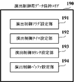
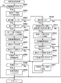
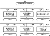
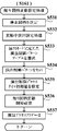
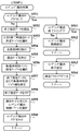
上記目的を達成するため、本願の請求項1に記載の遊技機は、始動条件(例えばステップS201におけるYesの判定とステップS202におけるNoの判定に基づき、ステップS203〜S209の処理が実行されたこと、あるいは、ステップS210におけるYesの判定とステップS211におけるNoの判定に基づき、ステップS212〜S218の処理が実行されたことなど)が成立した後に開始条件(例えばステップS241にてNoと判定されたことなど)が成立したことに基づいて、各々が識別可能な複数種類の識別情報(例えば特別図柄や飾り図柄など)を可変表示する可変表示手段(例えば第1及び第2特別図柄表示装置4A、4Bや画像表示装置5など)を備え、前記識別情報の可変表示結果が予め定められた特定表示結果(例えば大当り図柄や大当り組合せの確定飾り図柄など)となった後に、遊技者にとって有利な特定遊技状態(例えば大当り遊技状態など)に制御する遊技機(例えばパチンコ遊技機1など)であって、前記特定遊技状態に制御するか否かを、可変表示結果が導出表示される以前に判定する事前判定手段(例えばCPU103がステップS252の処理を実行する部分など)と、前記特定遊技状態が終了した後の遊技状態を、前記特定表示結果となる確率が通常状態よりも高い高確率状態(例えば高確高ベース状態や高確低ベース状態など)に制御する高確率状態制御手段(例えばCPU103がステップS322の処理を実行した後、ステップS250〜S252の処理を実行する部分など)と、前記高確率状態を終了させるか否かの終了判定確率を、複数種類のいずれかに設定する終了判定確率設定手段(例えばCPU103がステップS324、S325の処理を実行した後、ステップS401〜S404の処理を実行する部分など)と、前記高確率状態に制御されているときに、当該高確率状態の制御を終了するか否かを、前記終了判定確率設定手段によって設定された終了判定確率で判定する終了判定手段(例えばCPU103がステップS405、S406の処理を実行する部分など)と、前記終了判定手段によって終了すると判定されたときに、前記高確率状態制御手段による高確率状態の制御を終了する高確率終了制御手段(例えばCPU103がステップS407の処理を実行した後、ステップS250〜S252の処理を実行する部分など)と、前記終了判定確率設定手段によって設定された終了判定確率を示唆する示唆演出を実行する演出実行手段(例えば演出制御用CPU120がステップS504〜S508、S511〜S515の処理を実行する部分や、ステップS46の演出制御プロセス処理において、ステップS533及びステップS534の処理を実行した後にステップS544の処理を実行する部分、ステップS552〜S555の処理を実行する部分、あるいは、ステップST15におけるYesの判定に基づきステップST16の処理を実行する部分など)と、前記高確率状態制御手段により前記高確率状態に制御されているときに前記可変表示手段による識別情報の可変表示が実行されるごとに、前記演出実行手段により前記示唆演出を実行するか否かを決定するとともに、実行する場合には前記示唆演出における演出態様を複数種類のいずれかに決定する演出決定手段とを備え、前記終了判定確率設定手段によって設定される終了判定確率には、第1確率と、該第1確率よりも前記高確率状態を終了すると判定される確率が高い第2確率とがあり、前記示唆演出の演出態様には、前記終了判定確率設定手段によって設定された終了判定確率が前記第1確率である可能性が高いことを示唆する第1演出態様と、前記第1確率である可能性が低いことを示唆する第2演出態様とがあり、前記演出決定手段は、前記終了判定確率設定手段によって設定された終了判定確率が前記第2確率であるときには、前記第1確率であるときよりも高い割合で、前記示唆演出を実行しないことに決定する。
In order to achieve the above object, in the gaming machine according to
請求項2に記載の遊技機においては、前記演出実行手段により前記示唆演出を実行する演出状態として、前記可変表示手段による複数回の識別情報の可変表示中において特定の第1演出画像(例えばキャラクタCH2を示す演出画像など)を表示させる第1演出状態(例えば演出モードMD1など)と、前記可変表示手段による複数回の識別情報の可変表示中において前記第1演出画像とは異なる第2演出画像(例えばキャラクタCH3を示す演出画像など)を表示させる第2演出状態(例えば演出モードMD2など)とのうち、いずれかに制御する演出状態制御手段(例えば演出制御用CPU120がステップS559の処理を実行した後、ステップS533及びステップS534の処理を実行してからステップS544の処理を実行する部分など)と、前記高確率状態制御手段により高確率状態の制御が開始されるときに、前記演出状態制御手段により前記第1演出状態と前記第2演出状態のいずれに制御するかを、前記終了判定確率設定手段によって設定される終了判定確率に応じて異なる状態決定確率で決定する演出状態決定手段(例えば演出制御用CPU120がステップS552〜S555の処理を実行する部分など)とを備える。
In the gaming machine according to
請求項3に記載の遊技機においては、前記高確率状態制御手段による高確率状態の制御が終了した後に、前記演出実行手段による前記示唆演出の実行を継続するか否かを判定する演出継続判定手段(例えばステップS518にてYesの判定がなされた後に、演出制御用CPU120がステップS504、S508の処理を実行する部分や、ステップS511あるいはステップS514におけるNoの判定、および、ステップS606におけるNoの判定に基づき、ステップS609の処理を実行する部分など)を備える。
In the gaming machine according to
請求項4に記載の遊技機においては、前記高確率状態制御手段による高確率状態の制御が開始されるときに、前記可変表示手段による識別情報の可変表示時間が通常状態よりも短くなる時間短縮制御を行う時間短縮制御手段(例えばCPU103がステップS323の処理を実行した後に、ステップS279、S281の処理を実行する部分など)と、前記特定遊技状態が終了してから前記時間短縮制御手段による時間短縮制御を終了するまでに前記可変表示手段により識別情報の可変表示を実行する上限回数を、前記終了判定確率設定手段によって設定される終了判定確率に応じて異なる回数設定確率で、複数種類のいずれかに設定する可変表示回数設定手段(例えばCPU103がステップS324、S325の処理を実行した後、ステップS311〜S314の処理を実行する部分など)とを備える。
5. The gaming machine according to
請求項5に記載の遊技機においては、遊技者が操作可能な操作手段(例えば操作ボタン30など)を備え、前記演出実行手段は、前記可変表示手段により識別情報を可変表示中の所定期間に前記操作手段が操作されたタイミングにて、前記示唆演出を実行する(例えばステップST15におけるYesの判定に基づき、演出制御用CPU120がステップST16の処理を実行する部分など)。
According to a fifth aspect of the present invention, the game machine includes operation means (for example, the operation button 30) that can be operated by the player, and the effect execution means performs the identification information by the variable display means during a predetermined period during variable display. The suggestion effect is executed at a timing when the operation means is operated (for example, a portion where the
請求項6に記載の遊技機において、前記可変表示手段は、前記始動条件のうち第1始動条件(例えばステップS201におけるYesの判定とステップS202におけるNoの判定に基づき、ステップS203〜S209の処理が実行されたことなど)が成立した後に前記開始条件のうち第1開始条件(例えばステップS241にてNoと判定され、ステップS245にて第1と判定されたことなど)が成立したことに基づいて、各々が識別可能な複数種類の特別識別情報(例えば第1特図など)を可変表示する第1特別可変表示手段(第1特別図柄表示装置4Aなど)と、前記始動条件のうち第2始動条件(例えばステップS210におけるYesの判定とステップS211におけるNoの判定に基づき、ステップS212〜S218の処理が実行されたことなど)が成立した後に前記開始条件のうち第2開始条件(例えばステップS241にてNoと判定され、ステップS245にて第2と判定されたことなど)が成立したことに基づいて、各々が識別可能な複数種類の特別識別情報(例えば第2特図など)を可変表示する第2特別可変表示手段(第2特別図柄表示装置4Bなど)とを含み、前記終了判定手段は、前記第1開始条件が成立したときに高確率状態を終了するか否かと、前記第2開始条件が成立したときに高確率状態を終了するか否かとを、共通の処理モジュールを用いて判定する(例えばステップS15の特別図柄プロセス処理におけるステップS110の特別図柄通常処理にて実行されるステップS242の確変転落判定処理で、CPU103がステップS405、S406の処理を実行する部分など)。
7. The gaming machine according to
請求項7に記載の遊技機において、前記可変表示手段は、前記識別情報のうち特別識別情報(例えば特別図柄など)を可変表示する特別可変表示手段(例えば第1及び第2特別図柄表示装置4A、4Bなど)と、前記特別識別情報の可変表示に対応して、前記識別情報のうち装飾識別情報(例えば飾り図柄など)を可変表示する装飾可変表示手段(例えば画像表示装置5など)とを含み、前記特別識別情報には、前記特定表示結果に含まれる複数種類の特別識別情報(例えば図柄番号が「2」、「4」、「5」、「7」の特別図柄など)があり、前記終了判定確率設定手段は、前記特定表示結果として前記特別可変表示手段により導出表示された特別識別情報の種類に応じて異なる設定確率で、終了判定確率を複数種類のいずれかに設定する(例えばCPU103がステップS325にて設定した転落率指定バッファ値に基づき、ステップS401〜S404の処理を実行する部分など)。
8. The gaming machine according to
本発明は、以下に示す効果を有する。 The present invention has the following effects.
請求項1に記載の遊技機によれば、高確率状態を終了させるか否かの終了判定確率が、終了判定確率設定手段によって複数種類のいずれかに設定される。そして、演出実行手段は、終了判定確率を示唆する示唆演出を実行する。
これにより、高確率状態を終了させるか否かの判定確率に対する遊技者の期待感を示唆演出により高めて、遊技の興趣を向上させることができる。
According to the gaming machine of the first aspect, the end determination probability as to whether or not to end the high probability state is set to one of a plurality of types by the end determination probability setting means. Then, directing execution means executes a suggested directing suggesting the end determination probability.
Thereby, the player's sense of expectation with respect to the determination probability of whether or not to end the high probability state can be enhanced by the suggestion effect, and the interest of the game can be improved.
請求項2に記載の遊技機においては、それぞれ異なる演出画像を表示させる第1演出状態と第2演出状態のいずれに制御するかを、終了判定確率に応じて異なる状態決定確率で決定する。
これにより、遊技者は示唆演出を容易に認識することが可能になり、示唆演出による演出効果を高めて、遊技の興趣を向上させることができる。
In the gaming machine according to the second aspect, which of the first effect state and the second effect state for displaying different effect images is determined with different state determination probabilities according to the end determination probability.
Thereby, the player can easily recognize the suggestion effect, enhance the effect of the suggestion effect, and improve the interest of the game.
請求項3に記載の遊技機においては、高確率状態の制御が終了した後に、示唆演出の実行を継続するか否かを判定する。
これにより、高確率状態の制御が終了した後でも示唆演出は継続して行われることがあるため、高確率状態の終了後でも高確率状態である期待感を持続させ、遊技興趣の低下や客離れを防止することができる。
In the gaming machine according to
As a result, the suggestion effect may continue even after the control of the high probability state is completed, so that the expectation of the high probability state is maintained even after the high probability state ends, and the game entertainment interest and the customer are reduced. Separation can be prevented.
請求項4に記載の遊技機においては、特定遊技状態が終了してから時間短縮制御が終了するまでに実行される可変表示の上限回数を、高確率状態を終了させるか否かの終了判定確率に応じて異なる回数設定確率で、複数種類のいずれかに設定する。
これにより、示唆演出の他に、時間短縮制御が行われる可変表示の実行回数でも、高確率状態を終了させるか否かの終了判定確率を示唆することができ、高確率状態を終了させるか否かの判定確率に対する遊技者の期待感を持続させて、遊技の興趣を向上することができる。
In the gaming machine according to
As a result, in addition to the suggestion effect, the number of executions of variable display for which time reduction control is performed can also indicate the end determination probability of whether or not to end the high probability state, and whether or not to end the high probability state It is possible to maintain the player's expectation for such determination probability and improve the interest of the game.
請求項5に記載の遊技機においては、操作手段が操作されたタイミングにて示唆演出を実行する。
これにより、操作手段が操作されたときに実行される演出動作における演出効果を高めて、遊技の興趣を向上させることができる。
In the gaming machine according to the fifth aspect, the suggestion effect is executed at the timing when the operation means is operated.
Thereby, the stage effect in stage operation performed when the operation means is operated can be heightened, and the interest of a game can be improved.
請求項6に記載の遊技機においては、第1特別可変表示手段による可変表示を開始するための第1開始条件が成立したときと、第2特別可変表示手段による可変表示を開始するための第2開始条件が成立したときとで、共通の処理モジュールを用いて高確率状態を終了するか否かを判定する。
これにより、第1開始条件が成立したときの処理と第2開始条件が成立したときの処理とを共通化して、プログラム容量を低減することができる。
In the gaming machine according to
As a result, the processing when the first start condition is satisfied and the processing when the second start condition is satisfied can be shared, and the program capacity can be reduced.
請求項7に記載の遊技機においては、特別識別情報の可変表示に対応して装飾識別情報が可変表示される場合に、特定表示結果として導出表示された特別識別情報の種類に応じて異なる設定確率で、終了判定確率を複数種類のいずれかに設定することができる。
In the gaming machine according to
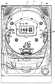
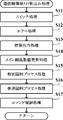
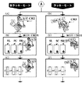
以下、図面を参照しつつ、本発明の一実施形態を詳細に説明する。図1は、本実施の形態におけるパチンコ遊技機の正面図であり、主要部材の配置レイアウトを示す。パチンコ遊技機(遊技機)1は、大別して、遊技盤面を構成する遊技盤(ゲージ盤)2と、遊技盤2を支持固定する遊技機用枠(台枠)3とから構成されている。遊技盤2には、ガイドレールによって囲まれた、ほぼ円形状の遊技領域が形成されている。この遊技領域には、遊技媒体としての遊技球が、所定の打球発射装置から発射されて打ち込まれる。
Hereinafter, an embodiment of the present invention will be described in detail with reference to the drawings. FIG. 1 is a front view of a pachinko gaming machine according to the present embodiment and shows an arrangement layout of main members. The pachinko gaming machine (gaming machine) 1 is roughly composed of a gaming board (gauge board) 2 constituting a gaming board surface and a gaming machine frame (base frame) 3 for supporting and fixing the
遊技盤2の所定位置(図1に示す例では、遊技領域の右側方)には、第1特別図柄表示装置4Aと、第2特別図柄表示装置4Bとが設けられている。第1特別図柄表示装置4Aと第2特別図柄表示装置4Bはそれぞれ、例えば7セグメントやドットマトリクスのLED(発光ダイオード)等から構成され、可変表示ゲームの一例となる特図ゲームにおいて、各々が識別可能な複数種類の識別情報(特別識別情報)である特別図柄(「特図」ともいう)を、変動可能に表示(可変表示)する。例えば、第1特別図柄表示装置4Aと第2特別図柄表示装置4Bはそれぞれ、「0」〜「9」を示す数字や「−」を示す記号等から構成される複数種類の特別図柄を可変表示する。なお、第1特別図柄表示装置4Aや第2特別図柄表示装置4Bにて表示される特別図柄は、「0」〜「9」を示す数字や「−」を示す記号等から構成されるものに限定されず、例えば7セグメントのLEDにおいて点灯させるものと消灯させるものとの組合せを異ならせた複数種類の点灯パターンが、複数種類の特別図柄として予め設定されていればよい。複数種類の特別図柄には、それぞれに対応した図柄番号が付されている。一例として、「0」〜「9」を示す数字それぞれには、「0」〜「9」の図柄番号が付され、「−」を示す記号には、「10」の図柄番号が付されていればよい。以下では、第1特別図柄表示装置4Aにより可変表示される特別図柄を「第1特図」ともいい、第2特別図柄表示装置4Bにより可変表示される特別図柄を「第2特図」ともいう。
A first special symbol display device 4A and a second special
遊技盤2における遊技領域の中央付近には、画像表示装置5が設けられている。画像表示装置5は、例えばLCD(液晶表示装置)等から構成され、各種の演出画像を表示する表示領域を形成している。画像表示装置5の表示領域では、特図ゲームにおける第1特別図柄表示装置4Aによる第1特図の可変表示や第2特別図柄表示装置4Bによる第2特図の可変表示のそれぞれに対応して、例えば3つといった複数に分割された可変表示部となる飾り図柄表示部にて、各々が識別可能な複数種類の識別情報(装飾識別情報)である飾り図柄を可変表示する。この飾り図柄の可変表示も、可変表示ゲームに含まれる。
An
一例として、画像表示装置5の表示領域には、「左」、「中」、「右」の飾り図柄表示部5L、5C、5Rが配置されている。そして、特図ゲームにおいて、第1特別図柄表示装置4Aによる第1特図の可変表示と、第2特別図柄表示装置4Bによる第2特図の可変表示とのうち、いずれかの可変表示が開始されることに対応して、「左」、「中」、「右」の飾り図柄表示部5L、5C、5Rの全部において飾り図柄の可変表示(例えば上下方向あるいは左右方向のスクロール表示など)が開始される。その後、特図ゲームにおける可変表示結果として確定特別図柄が停止表示(完全停止表示)されるときに、画像表示装置5における「左」、「中」、「右」の各飾り図柄表示部5L、5C、5Rにて、飾り図柄の可変表示結果となる確定飾り図柄(最終停止図柄)が停止表示(完全停止表示)される。なお、「左」、「中」、「右」の各飾り図柄表示部5L、5C、5Rは、画像表示装置5の表示領域内で移動可能とされ、飾り図柄を縮小あるいは拡大して表示することができるようにしてもよい。特別図柄や飾り図柄が完全停止表示されたときには、各図柄の可変表示における表示結果が確定的に表示され、それ以後は今回の可変表示が進行しないことを遊技者が認識できる表示状態となる。これに対して、飾り図柄の可変表示を開始してから可変表示結果となる確定飾り図柄が完全停止表示されるまでの可変表示中には、飾り図柄の変動速度が「0」となって、飾り図柄が停留して表示され、例えば微少な揺れや伸縮などを生じさせる表示状態となることがある。このような表示状態は、仮停止表示ともいい、可変表示における表示結果が確定的に表示されていないものの、スクロール表示や更新表示による飾り図柄の変動が進行していないことを遊技者が認識可能となる。なお、仮停止表示には、微少な揺れや伸縮なども生じさせず、所定時間(例えば1秒間)よりも短い時間だけ、飾り図柄を完全停止表示することなどが含まれてもよい。完全停止表示や仮停止表示のように、特別図柄や飾り図柄の変動が進行していないことを遊技者が認識できる程度に表示図柄を停止表示することは、導出表示ともいう。
As an example, “left”, “middle”, and “right” decorative
「左」、「中」、「右」の各飾り図柄表示部5L、5C、5Rにて可変表示される飾り図柄には、例えば8種類の図柄(英数字「1」〜「8」あるいは漢数字「一」〜「八」、英文字「A」〜「H」、所定のモチーフに関連する8個のキャラクタを示す演出画像、数字や文字あるいは記号とキャラクタとを組み合わせた演出画像など。なお、キャラクタを示す演出画像は、例えば人物や動物、これら以外の物体、もしくは、文字などの記号、あるいは、その他の任意の図形を示す画像であればよい。)が含まれていればよい。また、こうした8種類の飾り図柄の他に、ブランク図柄(大当り組合せを構成しない図柄)が含まれていてもよい。飾り図柄のそれぞれには、対応する図柄番号が付されている。例えば、「1」〜「8」を示す英数字それぞれに対して、「1」〜「8」の図柄番号が付されている。なお、可変表示される飾り図柄の種類数は、8種類のものに限定されず、任意の複数種類からなる飾り図柄であればよい。
The decorative symbols variably displayed on the “left”, “middle”, and “right” decorative
飾り図柄の変動中には、「左」、「中」、「右」の各飾り図柄表示部5L、5C、5Rにおいて、例えば図柄番号が小さいものから大きいものへと順次に、上方から下方へ、あるいは、右側から左側へと、流れるようなスクロール表示が行われる。そして、図柄番号が最大(例えば「8」)である飾り図柄が表示されると、続いて図柄番号が最小(例えば「1」)である飾り図柄が表示される。あるいは、飾り図柄表示部5L、5C、5Rのうち少なくともいずれか1つにおいて、図柄番号が大きいものから小さいものへとスクロール表示を行って、図柄番号が最小である飾り図柄が表示されると、続いて図柄番号が最大である飾り図柄が表示されるようにしてもよい。
While the decorative symbols are changing, in the decorative
画像表示装置5の表示領域には、始動入賞記憶表示部5Hも配置されている。始動入賞記憶表示部5Hでは、可変表示の保留数(特図保留記憶数)を特定可能に表示する保留記憶表示が行われる。ここで、可変表示の保留は、普通入賞球装置6Aが形成する第1始動入賞口や普通可変入賞球装置6Bが形成する第2始動入賞口に遊技球が進入(始動入賞)したときに発生する。すなわち、特図ゲームや飾り図柄の可変表示といった可変表示ゲームを実行するための始動条件(「実行条件」ともいう)は成立したが、先に成立した開始条件に基づく可変表示ゲームが実行中であることやパチンコ遊技機1が大当り遊技状態に制御されていることなどにより、可変表示ゲームを開始するための開始条件は成立していないときに、成立した始動条件に対応する可変表示の保留が行われる。
In the display area of the
一例として、始動入賞記憶表示部5Hには、始動入賞の発生に基づき先に始動条件が成立した可変表示ゲームから順に左から右へと、表示色が変更される複数の表示部位が設けられている。そして、第1始動入賞口に遊技球が進入したことに基づき第1特別図柄表示装置4Aにおける第1特図を用いた特図ゲームの始動条件(第1始動条件)が成立したときには、通常非表示(透過色)となっている表示部位のうちの1つ(例えば非表示となっている表示部位のうち左端の表示部位)を青色表示に変化させる。また、第2始動入賞口に遊技球が進入したことに基づき第2特別図柄表示装置4Bにおける第2特図を用いた特図ゲームの始動条件(第2始動条件)が成立したときには、通常非表示となっている表示部位のうちの1つを赤色表示に変化させる。その後、第1特図を用いた特図ゲームの開始条件(第1開始条件)と第2特図を用いた特図ゲームの開始条件(第2開始条件)のいずれかが成立したときには、例えば左端の表示部位における表示を除去するとともに、各表示部位における表示を1つずつ左方向に移動させる。このとき、青色表示や赤色表示に変化していた表示部位のうちの1つ(例えば表示色が変化していた表示部位のうち右端の表示部位)は、非表示に戻る。ここで、保留記憶表示を行う際に、可変表示ゲームの始動条件が成立したことに基づく特図保留記憶数は特定できたものの、その始動条件が第1始動条件であるか第2始動条件であるかを特定できない場合に、例えば特図保留記憶数に対応する個数の表示部位を灰色表示に変化させることなどにより、特図保留記憶数の表示態様を所定の表示態様に変更してもよい。
As an example, the start winning memory display unit 5H is provided with a plurality of display parts whose display colors are changed from left to right in order from the variable display game in which the start condition is established based on the occurrence of the start winning. Yes. When the start condition (first start condition) of the special figure game using the first special figure in the first special symbol display device 4A is established based on the game ball entering the first start winning opening, the One of the display parts that are displayed (transparent color) (for example, the leftmost display part among the non-displayed display parts) is changed to blue display. Further, when a special ball game start condition (second start condition) using the second special figure in the second special
なお、始動入賞記憶表示部5Hでは、特図保留記憶数を示す数字を表示することなどにより、特図保留記憶数を遊技者等が認識できるようにしてもよい。始動入賞記憶表示部5Hとともに、あるいは始動入賞記憶表示部5Hに代えて、特図保留記憶数を表示する表示器を設けるようにしてもよい。図1に示す例では、始動入賞記憶表示部5Hとともに、第1特別図柄表示装置4A及び第2特別図柄表示装置4Bの上部に、特図保留記憶数を特定可能に表示するための第1保留表示器25Aと第2保留表示器25Bとが設けられている。第1保留表示器25Aは、普通入賞球装置6Aが形成する第1始動入賞口に進入した有効始動入賞球数としての第1保留記憶数を特定可能に表示する。第2保留表示器25Bは、普通可変入賞球装置6Bが形成する第2始動入賞口に進入した有効始動入賞球数としての第2保留記憶数を特定可能に表示する。第1保留表示器25Aと第2保留表示器25Bはそれぞれ、例えば第1保留記憶数と第2保留記憶数のそれぞれにおける上限値(例えば「4」)に対応した個数(例えば4個)のLEDを含んで構成されている。
In the start winning memory display section 5H, a number indicating the special figure reserved memory number may be displayed so that the player or the like can recognize the special figure reserved memory number. A display for displaying the number of reserved special figure memories may be provided together with the start winning memory display unit 5H or instead of the start winning memory display unit 5H. In the example shown in FIG. 1, together with the start winning memory display section 5H, the first hold for displaying the number of special figure hold memories identifiable on the upper part of the first special symbol display device 4A and the second special
画像表示装置5の表示領域には、飾り図柄とは異なる識別情報としての色図柄を可変表示する色図柄表示エリアが設けられていてもよい。一例として、色図柄表示エリアには、第1特別図柄表示装置4Aによる第1特図を用いた特図ゲームが開始されるときに、色図柄の変動(例えば表示色の更新表示)が開始される「左」の色図柄表示部と、第2特別図柄表示装置4Bによる第2特図を用いた特図ゲームが開始されるときに、色図柄の変動が開始される「右」の色図柄表示部とが含まれていればよい。そして、特図ゲームにおいて可変表示結果となる確定特別図柄が完全停止表示されるときには、色図柄の変動が終了して、色図柄の可変表示結果となる確定色図柄が完全停止表示される。「左」及び「右」の色図柄表示部にて可変表示される色図柄には、例えば4種類の図柄(「黄色」、「緑色」、「赤色」、「青色」など)といった、複数種類の色図柄が含まれていればよい。色図柄のそれぞれには、対応する図柄番号が付されている。一例として、「黄色」、「緑色」、「赤色」、「青色」の色図柄それぞれに対して、「1」〜「4」の図柄番号が付されていればよい。
The display area of the
画像表示装置5の下方には、普通入賞球装置6Aと、普通可変入賞球装置6Bとが設けられている。普通入賞球装置6Aは、例えば所定の玉受部材によって常に一定の開放状態に保たれる第1始動入賞口を形成する。普通可変入賞球装置6Bは、所定の普通電動役物用ソレノイドによって垂直位置となる通常開放状態と傾動位置となる拡大開放状態とに変化する一対の可動翼片を有する電動チューリップ型役物(普通電動役物)を備え、第2始動入賞口を形成する。一例として、普通可変入賞球装置6Bでは、普通電動役物用ソレノイドがオフ状態であるときに可動翼片が垂直位置となることにより、遊技球が第2始動入賞口に進入しにくい通常開放状態となる。その一方で、普通可変入賞球装置6Bでは、普通電動役物用ソレノイドがオン状態であるときに可動翼片が傾動位置となることにより、遊技球が第2始動入賞口に進入しやすい拡大開放状態となる。なお、普通可変入賞球装置6Bは、通常開放状態であるときでも、第2始動入賞口には遊技球が進入可能であるものの、拡大開放状態であるときよりも遊技球が進入する可能性が低くなるように構成してもよい。あるいは、普通可変入賞球装置6Bは、通常開放状態において、例えば第2始動入賞口を閉鎖することなどにより、第2始動入賞口には遊技球が進入しないように構成してもよい。
Below the
普通入賞球装置6Aに形成された第1始動入賞口に進入した遊技球は、例えば図2に示す第1始動口スイッチ22Aによって検出される。普通可変入賞球装置6Bに形成された第2始動入賞口に進入した遊技球は、例えば図2に示す第2始動口スイッチ22Bによって検出される。第1始動口スイッチ22Aによって遊技球が検出されたことに基づき、所定個数(例えば3個)の遊技球が賞球として払い出され、第1保留記憶数が所定の上限値(例えば「4」)以下であれば、第1始動条件が成立する。第2始動口スイッチ22Bによって遊技球が検出されたことに基づき、所定個数(例えば3個)の遊技球が賞球として払い出され、第2保留記憶数が所定の上限値以下であれば、第2始動条件が成立する。なお、第1始動口スイッチ22Aによって遊技球が検出されたことに基づいて払い出される賞球の個数と、第2始動口スイッチ22Bによって遊技球が検出されたことに基づいて払い出される賞球の個数は、互いに同一の個数であってもよいし、異なる個数であってもよい。
A game ball that has entered the first start winning opening formed in the normal
普通入賞球装置6Aと普通可変入賞球装置6Bの下方には、特別可変入賞球装置7が設けられている。特別可変入賞球装置7は、所定の大入賞口扉用ソレノイドによって開閉駆動される大入賞口扉を備え、その大入賞口扉によって開放状態(第1状態)と閉鎖状態(第2状態)とに変化する大入賞口を形成する。一例として、特別可変入賞球装置7では、大入賞口扉用ソレノイドがオフ状態であるときに大入賞口扉が大入賞口を閉鎖状態にする。その一方で、特別可変入賞球装置7では、大入賞口扉用ソレノイドがオン状態であるときに大入賞口扉が大入賞口を開放状態にする。特別可変入賞球装置7に形成された大入賞口に進入した遊技球は、例えば図2に示すカウントスイッチ23によって検出される。カウントスイッチ23によって遊技球が検出されたことに基づき、所定個数(例えば14個)の遊技球が賞球として払い出される。
A special variable winning
遊技盤2の所定位置(図1に示す例では、遊技領域の左側方)には、普通図柄表示器20が設けられている。一例として、普通図柄表示器20は、第1特別図柄表示装置4Aや第2特別図柄表示装置4Bと同様に7セグメントやドットマトリクスのLED等から構成され、特別図柄とは異なる複数種類の識別情報である普通図柄(「普図」あるいは「普通図」ともいう)を変動可能に表示(可変表示)する。このような普通図柄の可変表示は、普図ゲーム(「普通図ゲーム」ともいう)と称される。普通図柄表示器20は、例えば「0」〜「9」を示す数字や「−」を示す記号等から構成される複数種類の普通図柄を可変表示する。複数種類の普通図柄には、それぞれに対応した図柄番号が付されている。一例として、「0」〜「9」を示す数字それぞれには、「0」〜「9」の図柄番号が付され、「−」を示す記号には、「10」の図柄番号が付されていればよい。なお、普通図柄表示器20は、「0」〜「9」を示す数字や「−」を示す記号等を普通図柄として可変表示するものに限定されず、例えば「○」と「×」とを示す装飾ランプ(またはLED)を交互に点灯させることや、「左」、「中」、「右」といった複数の装飾ランプ(またはLED)を所定順序で点灯させることにより、普通図柄を可変表示するものであってもよい。普通図柄表示器20の上方には、普図保留表示器25Cが設けられている。普図保留表示器25Cは、例えば4個のLEDを含んで構成され、通過ゲート41を通過した有効通過球数としての普図保留記憶数を表示する。
A
遊技盤2の表面には、上記の構成以外にも、遊技球の流下方向や速度を変化させる風車及び多数の障害釘が設けられている。また、第1始動入賞口、第2始動入賞口及び大入賞口とは異なる入賞口として、例えば所定の玉受部材によって常に一定の開放状態に保たれる一般入賞口が1つ又は複数設けられてもよい。この場合には、一般入賞口のいずれかに進入した遊技球が所定の一般入賞球スイッチによって検出されたことに基づき、所定個数(例えば10個)の遊技球が賞球として払い出されればよい。遊技領域の最下方には、いずれの入賞口にも進入しなかった遊技球が取り込まれるアウト口が設けられている。遊技機用枠3の左右上部位置には、効果音等を再生出力するためのスピーカ8L、8Rが設けられており、さらに遊技領域周辺部には、遊技効果ランプ9が設けられている。パチンコ遊技機1の遊技領域における各構造物(例えば普通入賞球装置6A、普通可変入賞球装置6B、特別可変入賞球装置7等)の周囲には、装飾用LEDが配置されていてもよい。
In addition to the above-described configuration, the surface of the
遊技機用枠3の右下部位置には、遊技媒体としての遊技球を遊技領域に向けて発射するために遊技者等によって操作される打球操作ハンドル(操作ノブ)が設けられている。例えば、打球操作ハンドルは、遊技者等による操作量(回転量)に応じて遊技球の弾発力を調整する。打球操作ハンドルには、打球発射装置が備える発射モータの駆動を停止させるための単発発射スイッチや、タッチリング(タッチセンサ)が設けられていればよい。遊技領域の下方における遊技機用枠3の所定位置には、賞球として払い出された遊技球や所定の球貸機により貸し出された遊技球を、打球発射装置へと供給可能に保持(貯留)する上皿が設けられている。例えば上皿の上面における手前側の中央位置といった、パチンコ遊技機1の遊技機用枠3における所定位置には、押下操作などにより遊技者が操作可能な操作ボタン30が設置されている。なお、操作ボタン30は、押下操作が可能なものに限定されず、例えば回転型セレクタのような回転操作が可能なものであってもよいし、タッチパネルのように接触操作や押圧操作が可能なものであってもよいし、レバー型スイッチのような傾動操作が可能なものであってもよい。また、操作ボタン30に代えて、例えば赤外線センサやCCDセンサ、CMOSセンサのように、遊技者による所定の操作行為を検出できるセンサを用いてもよい。すなわち、操作ボタン30は、遊技者による所定の操作行為を、機械的、電気的、あるいは、電磁的に、検出できるものであればよい。
At the lower right position of the
普通図柄表示器20による普図ゲームは、遊技領域に設けられた通過ゲート41を通過した遊技球が図2に示すゲートスイッチ21によって検出されたことといった、普通図柄表示器20にて普通図柄の可変表示を実行するための普図始動条件が成立した後に、例えば前回の普図ゲームが終了したことといった、普通図柄の可変表示を開始するための普図開始条件が成立したことに基づいて、開始される。この普図ゲームでは、普通図柄の変動を開始させた後、所定の可変表示時間が経過すると、普通図柄の可変表示結果となる確定普通図柄を完全停止表示する。普通図柄の可変表示時間は、例えば各普図ゲームの開始時に、所定の乱数値を示す数値データを抽出することなどにより、複数種類の可変表示時間のうちで、いずれかに決定されればよい。普図ゲームにおける普通図柄の可変表示結果となる確定普通図柄として、例えば「7」を示す数字といった、特定の普通図柄(普図当り図柄)が停止表示されれば、普通図柄の可変表示結果が「普図当り」となる。その一方、確定普通図柄として、例えば「7」を示す数字以外の数字や記号といった、普図当り図柄以外の普通図柄が停止表示されれば、普通図柄の可変表示結果が「普図ハズレ」となる。普通図柄の可変表示結果が「普図当り」となったことに対応して、普通可変入賞球装置6Bを構成する電動チューリップの可動翼片が傾動位置となる拡大開放制御が行われ、所定時間が経過すると垂直位置に戻る通常開放制御が行われる。
In the normal game with the
第1特別図柄表示装置4Aによる特図ゲームは、普通入賞球装置6Aに形成された第1始動入賞口に進入した遊技球が図2に示す第1始動口スイッチ22Aによって検出されたことなどにより第1始動条件が成立した後に第1開始条件が成立したことに基づいて、開始される。第1開始条件は、例えば前回の特図ゲームや大当り遊技状態が終了したときなどに、第1特図を用いた今回の特図ゲームが開始可能となることにより成立する。第2特別図柄表示装置4Bによる特図ゲームは、普通可変入賞球装置6Bに形成された第2始動入賞口に進入した遊技球が図2に示す第2始動口スイッチ22Bによって検出されたことなどにより第2始動条件が成立した後に第2開始条件が成立したことに基づいて、開始される。第2開始条件は、例えば前回の特図ゲームや大当り遊技状態が終了したときなどに、第2特図を用いた今回の特図ゲームが開始可能となることにより成立する。
The special symbol game by the first special symbol display device 4A is caused by the fact that the game ball that has entered the first starting winning port formed in the normal
第1特別図柄表示装置4Aや第2特別図柄表示装置4Bによる特図ゲームでは、特別図柄の可変表示を開始させた後、所定の可変表示時間が経過すると、特別図柄の可変表示結果となる確定特別図柄を完全停止表示する。特別図柄の可変表示時間は、各特図ゲームの開始時に、例えば図4に示すような変動パターン決定用の乱数値MR5を示す数値データなどに基づいて決定された変動パターンに対応して、複数種類の可変表示時間のうちで、いずれかに決定される。特図ゲームにおける特別図柄の可変表示結果となる確定特別図柄として、特定の特別図柄(大当り図柄)が停止表示されれば、特定表示結果としての「大当り」となり、大当り図柄以外の特別図柄(ハズレ図柄)が停止表示されれば、非特定表示結果としての「ハズレ」となる。特図ゲームでの可変表示結果が「大当り」になった後には、特定遊技状態としての大当り遊技状態に制御される。この実施の形態におけるパチンコ遊技機1では、一例として、図柄番号が「2」、「4」、「5」、「7」である4つの特別図柄を大当り図柄とし、図柄番号が「10」である特別図柄をハズレ図柄としている。なお、第1特別図柄表示装置4Aによる特図ゲームにおける大当り図柄やハズレ図柄といった各図柄は、第2特別図柄表示装置4Bによる特図ゲームにおける各図柄とは異なる特別図柄となるようにしてもよいし、双方の特図ゲームにおいて共通の特別図柄が大当り図柄やハズレ図柄となるようにしてもよい。
In the special symbol game by the first special symbol display device 4A or the second special
特図ゲームにおける確定特別図柄として大当り図柄が停止表示された後に制御される特定遊技状態としての大当り遊技状態では、特別可変入賞球装置7の開閉板が、所定期間(例えば29秒間)あるいは所定個数(例えば10個)の入賞球が発生するまでの期間にて大入賞口を開放状態とすることにより、特別可変入賞球装置7を遊技者にとって有利な第1状態に変化させるラウンドが実行される。こうしてラウンド中に大入賞口を開放状態とした開閉板は、遊技盤2の表面を落下する遊技球を受け止め、その後に大入賞口を閉鎖状態とすることにより、特別可変入賞球装置7を遊技者にとって不利な第2状態に変化させて、1回のラウンドを終了させる。この実施の形態では、大当り遊技状態において、大入賞口の開放サイクルであるラウンドを、所定の実行回数(例えば「15」)に達するまで繰り返すことができる。
In the big hit game state as the specific game state controlled after the big hit symbol is stopped and displayed as the confirmed special symbol in the special figure game, the opening / closing plate of the special variable winning
なお、特別可変入賞球装置7の開閉板は、例えばパチンコ遊技機1の電源投入後に大当り遊技状態へと制御される以前までのような通常時には、大入賞口を閉鎖状態としている。大当り遊技状態において開放状態となった大入賞口に入賞して遊技盤2の背面に導かれた遊技球のうち一方の領域(V入賞領域;特別領域)に入ったものは所定のV入賞スイッチで検出された後にカウントスイッチ23で検出され、他方の領域に入った遊技球は、V入賞スイッチで検出されずに、そのままカウントスイッチ23で検出されるようにしてもよい。この場合、遊技盤2の背面には、大入賞口内の経路を切り替えるためのソレノイドが設けられていてもよい。そして、大当り遊技状態における最終ラウンド以外の各ラウンドでは、V入賞スイッチによって遊技球が検出されることが、次のラウンドへと移行できるための条件となるようにしてもよい。あるいは、V入賞領域を設けずに、大当り遊技状態における最終ラウンド以外の各ラウンドでは、常に次のラウンドへと移行できるようにしてもよい。
Note that the opening / closing plate of the special variable winning
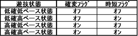
大当り遊技状態が終了した後には、複数種類の特別遊技状態のうちの1つである高確高ベース状態となる。ここで、この実施の形態では、特別遊技状態として、高確高ベース状態の他に、高確低ベース状態や、低確高ベース状態といった、複数種類の遊技状態が設けられている。高確高ベース状態や低確高ベース状態といった、高ベース状態(「時短状態」あるいは「時間短縮状態」ともいう)を含む遊技状態では、通常状態である低確低ベース状態などの低ベース状態を含む遊技状態に比べて、普通図柄表示器20による普図ゲームにおける普通図柄の変動時間(普図変動時間)を短くする制御や、各回の普図ゲームで普通図柄の可変表示結果が「普図当り」となる確率を向上させる制御、可変表示結果が「普図当り」となったことに基づく普通可変入賞球装置6Bにおける可動翼片の傾動時間を長くする制御、その傾動回数を増加させる制御といった、第2始動入賞口に遊技球が進入する可能性を低ベース状態を含む遊技状態に比べて高め、第2始動条件が成立しやすくなることで遊技者にとって有利となる有利開放制御が行われる。なお、高ベース状態を含む遊技状態では、これらの制御のいずれか1つが行われるようにしてもよいし、複数の制御が組み合わせられて行われるようにしてもよい。また、高ベース状態を含む遊技状態では、特図ゲームにおける平均的な特別図柄の変動時間(可変表示時間)が短縮される時短制御が行われる。高確高ベース状態や高確低ベース状態といった、高確状態(「確変状態」あるいは「高確率状態」ともいう)を含む遊技状態では、確変制御が行われることにより、低確低ベース状態や低確高ベース状態などの低確状態を含む遊技状態に比べて、各特図ゲームや飾り図柄の可変表示における可変表示結果が「大当り」となって更に大当り遊技状態に制御される確率が、高くなるように向上する。通常状態である低確低ベース状態は、大当り遊技状態等の特定遊技状態や、時短制御および確変制御のうち少なくともいずれか一方が行われる特別遊技状態とは異なる遊技状態であり、パチンコ遊技機1の初期設定状態(例えばシステムリセットが行われた場合のように、電源投入後に初期化処理を実行した状態)と同一の制御が行われる。
After the big hit gaming state ends, the high-accuracy base state, which is one of a plurality of types of special gaming states, is obtained. Here, in this embodiment, as the special game state, in addition to the highly accurate and high base state, a plurality of types of game states such as a highly accurate and low base state and a low probability and high base state are provided. In a gaming state that includes a high base state (also referred to as a “short-time state” or “short time state”), such as a high-accuracy base state or a low-accuracy base state, a low base state such as a low-accuracy low base state that is a normal state Compared to the game state including the
この実施の形態において、高ベース状態を含む遊技状態における有利開放制御や時短制御は、所定回数(例えば100回あるいは20回)の特図ゲームが実行されることと、可変表示結果が「大当り」となることのうち、いずれかの条件が先に成立したときに、終了する。高ベース状態を含む遊技状態において実行可能な特図ゲームの上限回数は、可変表示結果が「大当り」となるときの大当り図柄の種類(大当り種別)に応じた回数設定確率で、複数種類(例えば100回あるいは20回)のいずれかに設定される。高確高ベース状態において、可変表示結果が「大当り」となるより前に、特図ゲームの実行回数が上限回数に達したことにより高ベース状態を終了するときには、パチンコ遊技機1における遊技状態が高確低ベース状態となる。また、低確高ベース状態において、可変表示結果が「大当り」となるより前に、特図ゲームの実行回数が上限回数に達したことにより高ベース状態を終了するときには、パチンコ遊技機1における遊技状態が低確低ベース状態となる。
In this embodiment, the advantageous release control and the time-saving control in the gaming state including the high base state are executed by a predetermined number of times (for example, 100 times or 20 times), and the variable display result is “big hit”. The process ends when any of the conditions is satisfied first. The upper limit number of special figure games that can be executed in the game state including the high base state is the number setting probability according to the type of jackpot symbol (big jackpot type) when the variable display result is “big jackpot”, and the number of types (for example, 100 times or 20 times). In the high-accuracy high-base state, when the high-base state is terminated because the number of executions of the special figure game has reached the upper limit before the variable display result becomes “big hit”, the gaming state in the
高確状態を含む遊技状態では、特図ゲームが実行されるごとに、確変制御を終了するか否かが判定される。こうした特図ゲームが実行されるごとに行われる確変制御を終了するか否かの判定は、「確変転落判定」や「確変転落抽選」あるいは「確変パンク抽選」とも称される。確変転落判定にて確変制御を終了させるか否かの終了判定確率は、可変表示結果が「大当り」となるときの大当り図柄の種類(大当り種別)に応じた設定確率で、複数種類(例えば1/100あるいは1/5)のいずれかに設定される。また、高ベース状態を含む遊技状態における確変制御は、可変表示結果が「大当り」となったときにも終了する。高確高ベース状態における確変転落判定にて、確変制御を終了する旨の判定がなされたことにより、高確状態を終了するときに、高ベース状態の制御が継続されるのであれば、パチンコ遊技機1における遊技状態が低確高ベース状態となる。また、高確低ベース状態における確変転落判定にて、確変制御を終了する旨の判定がなされたことにより、高確状態を終了するときには、パチンコ遊技機1における遊技状態が低確低ベース状態となる。
In the gaming state including the high probability state, it is determined whether or not the probability variation control is terminated every time the special game is executed. The determination as to whether or not to end the probability variation control that is performed each time such a special game is executed is also referred to as “probability variation fall determination”, “probability variation fall lottery”, or “probability variation puncture lottery”. The end determination probability as to whether or not the probability variation control is to be terminated in the probability variation fall determination is a set probability according to the type of jackpot symbol (big hit type) when the variable display result is “big hit”, and a plurality of types (for example, 1 / 100 or 1/5). In addition, the probability variation control in the gaming state including the high base state is also ended when the variable display result is “big hit”. If it is determined that the probability variation control is to be terminated in the probability variation fall determination in the highly accurate high base state, if the high base state control is continued when the high probability state is terminated, a pachinko game The gaming state in the
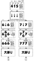
この実施の形態では、4種類の大当り種別として、大当り種別SP1〜大当り種別SP4が、予め定められている。大当り種別SP1は、図柄番号「7」の特別図柄が特図ゲームの可変表示結果である確定特別図柄として導出表示される場合における特別図柄や飾り図柄の可変表示態様である。大当り種別SP2は、図柄番号「5」の特別図柄が確定特別図柄として導出表示される場合における特別図柄や飾り図柄の可変表示態様である。大当り種別SP3は、図柄番号「4」の特別図柄が確定特別図柄として導出表示される場合における特別図柄や飾り図柄の可変表示態様である。大当り種別SP4は、図柄番号「2」の特別図柄が確定特別図柄として導出表示される場合における特別図柄や飾り図柄の可変表示態様である。 In this embodiment, the big hit type SP1 to the big hit type SP4 are determined in advance as the four types of big hit types. The jackpot type SP1 is a variable display mode of a special symbol or a decorative symbol when the special symbol of the symbol number “7” is derived and displayed as a fixed special symbol which is a variable display result of the special symbol game. The jackpot type SP2 is a variable display mode of a special symbol or a decorative symbol when the special symbol of the symbol number “5” is derived and displayed as a confirmed special symbol. The jackpot type SP3 is a variable display mode of a special symbol or a decorative symbol when the special symbol of the symbol number “4” is derived and displayed as a confirmed special symbol. The jackpot type SP4 is a variable display mode of a special symbol or a decorative symbol when the special symbol of the symbol number “2” is derived and displayed as a confirmed special symbol.
画像表示装置5の表示画面では、第1特別図柄表示装置4Aや第2特別図柄表示装置4Bによる特別図柄の可変表示に対応して、飾り図柄の可変表示が行われる。すなわち、画像表示装置5の表示画面では、第1開始条件と第2開始条件のいずれか一方が成立したことに基づいて、例えば「左」、「中」、「右」の飾り図柄表示部5L、5C、5Rにおける全部にて飾り図柄の加速表示(全図柄加速表示)を行い、所定速度に達すれば、飾り図柄の定速表示(全図柄定速表示)を行う。こうした全図柄加速表示や全図柄定速表示は、「左」、「中」、「右」の飾り図柄表示部5L、5C、5Rの全部にて飾り図柄を可変表示する全図柄変動に含まれる。こうした全図柄変動の後、例えば「左」→「右」→「中」といった所定順序で飾り図柄の減速表示(各図柄減速表示)を行い、変動速度が「0」となれば、飾り図柄を停留して表示する一方で、例えば微少な揺れや伸縮などを生じさせる仮停止表示を行う。そして、飾り図柄の可変表示を開始してからの経過時間が変動パターンなどに基づいて決定された可変表示時間に達したときには、可変表示結果となる確定飾り図柄を完全停止表示する。なお、確定飾り図柄を停止表示する手順としては、「左」、「中」、「右」の飾り図柄表示部5L、5C、5Rにおいて所定順序で飾り図柄を減速表示するものに限定されず、「左」、「中」、「右」の各飾り図柄表示部5L、5C、5Rにおいて同時に確定飾り図柄となる飾り図柄を減速表示(全図柄減速表示)するものが含まれていてもよい。
On the display screen of the
全図柄変動が開始された後には、「左」、「中」、「右」の飾り図柄表示部5L、5C、5Rのうち全部または一部の飾り図柄表示部にて、飾り図柄をリーチ表示状態で導出表示することがある。ここで、リーチ表示状態とは、画像表示装置5の表示画面にて導出表示された飾り図柄が大当り組合せの一部を構成しているときに未だ導出表示されていない飾り図柄(「リーチ変動図柄」ともいう)については変動が継続している表示状態、あるいは、全部または一部の飾り図柄が大当り組合せの全部または一部を構成しながら同期して変動している表示状態のことである。具体的には、「左」、「中」、「右」の飾り図柄表示部5L、5C、5Rにおける一部(例えば「左」及び「右」の飾り図柄表示部5L、5Rなど)では予め定められた大当り組合せを構成する飾り図柄(例えば「7」の英数字を示す飾り図柄)が導出表示されているときに未だ導出表示されていない残りの飾り図柄表示部(例えば「中」の飾り図柄表示部5Cなど)では飾り図柄が変動している表示状態、あるいは、「左」、「中」、「右」の飾り図柄表示部5L、5C、5Rにおける全部または一部で飾り図柄が大当り組合せの全部または一部を構成しながら同期して変動している表示状態である。また、リーチ表示状態となったことに対応して、画像表示装置5の表示画面に飾り図柄とは異なるアニメーション画像や実写画像といった演出画像を表示させたり、背景画像の表示態様を変化させたり、飾り図柄の変動態様を変化させたりすることがある。このような演出画像の表示や背景画像の表示態様の変化、飾り図柄の変動態様の変化を、リーチ演出表示(あるいは単にリーチ演出)という。リーチ演出の中には、それが出現すると、通常のリーチ演出(ノーマルリーチ)に比べて大当りが発生しやすい(高い確率で大当りとなる)ように設定されたものがある。このような特別のリーチ演出を、スーパーリーチ演出(あるいは単に「スーパーリーチ」)ともいう。一例として、スーパーリーチとなるリーチ演出には、ノーマルリーチと同様のリーチ演出を所定時間が経過するまで行ってから、例えば背景画像の表示態様や、表示されるキャラクタ、飾り図柄の変動方向といった飾り図柄の変動態様のうち、少なくともいずれか1つがリーチ表示状態となる以前やノーマルリーチのときとは異なるものとなることにより、演出態様が変化(いわゆる「発展」)して、スーパーリーチに特有のリーチ演出における導入部分が開始されるものが含まれていればよい。また、スーパーリーチとなるリーチ演出には、飾り図柄がリーチ表示状態で導出表示されたときに、ノーマルリーチと同様のリーチ演出を行うことなく、スーパーリーチに特有のリーチ演出における導入部分が開始されるものが含まれていてもよい。
After all symbols change is started, the decorative symbols are reach-displayed on all or some of the decorative
飾り図柄の可変表示中には、リーチ演出とは異なり、例えば全図柄変動が開始されてから飾り図柄の可変表示状態がリーチ表示状態となるより前に、所定のキャラクタ画像やメッセージ画像などを表示することといった、飾り図柄の可変表示態様以外の表示態様により、飾り図柄の可変表示状態がリーチ表示状態となる可能性があることや、可変表示結果が「大当り」となる可能性があることを、遊技者に報知するための予告演出が実行されることがある。ここで、飾り図柄の可変表示状態がリーチ表示状態となる可能性があることを遊技者に報知するための予告演出は、特に「リーチ予告演出」ともいう。予告演出となる演出動作は、全図柄変動が開始されてから、飾り図柄の可変表示状態がリーチ表示状態となるより前に実行(開始)されるものであればよい。この実施の形態では、「予告セリフ演出」となる予告演出が実行可能に設定されている。予告演出となる演出動作は、それが実行されるか否かによっては特別図柄の可変表示時間に変化が生じないものであればよい。また、「予告セリフ演出」となる予告演出の他にも、複数種類の予告演出のいずれかが選択されて実行されるようにしてもよい。 During the variable display of decorative symbols, unlike a reach effect, for example, a predetermined character image or message image is displayed before the variable graphic display state reaches the reach display state after all symbol variations have started. Depending on the display mode other than the variable display mode of the decorative design, such as, the variable display status of the decorative design may be the reach display status, and the variable display result may be “big hit” A notice effect for informing the player may be executed. Here, the notice effect for notifying the player that there is a possibility that the variable display state of the decorative symbol becomes the reach display state is particularly referred to as “reach notice effect”. The effect operation as the notice effect may be executed (started) after all the symbol changes are started and before the decorative symbol variable display state becomes the reach display state. In this embodiment, a notice effect that is a “notice line effect” is set to be executable. The effect operation that becomes the notice effect may be any effect that does not cause a change in the variable symbol display time depending on whether or not it is executed. In addition to the notice effect that becomes the “notice line effect”, any of a plurality of types of notice effects may be selected and executed.
「予告セリフ演出」となる予告演出では、全図柄変動が開始されてから、2つ以上の飾り図柄表示部(例えば「左」及び「右」の飾り図柄表示部5L、5Rなど)にて飾り図柄が導出表示されるより前に、ボタン操作促進演出となる所定の演出動作が行われる。ボタン操作促進演出は、例えば画像表示装置5の表示画面における所定位置に、予め用意されたキャラクタ画像やメッセージ画像といった演出画像を表示させることなどにより、遊技者による操作ボタン30の操作を促す演出動作であればよい。遊技者による操作ボタン30の操作を促す演出動作としては、画像表示装置5に演出画像を表示させるものに限定されず、スピーカ8L、8Rから所定の音声を出力させるもの、遊技効果ランプ9や装飾用LEDを所定の点灯パターンで点灯あるいは点滅させるもの、遊技領域内あるいは遊技領域外に設けられた演出用役物が備える可動部材を所定の動作態様で動作させるもの、あるいは、これらのいずれかを組み合わせたものであってもよい。こうしたボタン操作促進演出が行われるときには、遊技者による操作ボタン30の操作を有効に検出する操作有効期間となる。そして、操作有効期間内に遊技者による操作ボタン30の操作が検出されると、その操作が検出されたタイミングにて、ボタン操作促進演出の実行を停止するとともに、予め用意された複数種類のセリフ(予告セリフ)のうち、いずれかの予告セリフを示すメッセージ画像を画像表示装置5に表示させるなどの演出動作が実行される。なお、予告セリフを報知する演出動作として、例えばスピーカ8L、8Rから所定の音声を出力させるといった、各種の演出動作が行われてもよい。
In the notice effect that is the “notice line effect”, the decoration is displayed on two or more decorative symbol display parts (for example, the “left” and “right” decorative
飾り図柄の可変表示中には、リーチ演出や予告演出とは異なり、飾り図柄の可変表示状態がリーチ状態となる可能性があることや、可変表示結果が「大当り」となる可能性があることを、飾り図柄の可変表示態様などにより遊技者に報知するための特定演出が実行されてもよい。例えば、「滑り」や「擬似連」といった特定演出が実行可能に設定されていてもよい。特定演出が実行される場合には、特定演出が実行されない場合に比べて、可変表示時間が長くなるようにしてもよい。「滑り」の特定演出では、「左」、「中」、「右」の飾り図柄表示部5L、5C、5Rにおける全部にて飾り図柄を変動させてから、2つ以上の飾り図柄表示部(例えば「左」及び「右」の飾り図柄表示部5L、5Rなど)にて飾り図柄を仮停止表示させた後、その仮停止表示した飾り図柄表示部のうち所定数(例えば「1」または「2」)の飾り図柄表示部(例えば「左」の飾り図柄表示部5Lと「右」の飾り図柄表示部5Rのいずれか一方または双方)にて飾り図柄を再び変動させた後に停止表示させることで、停止表示する飾り図柄を変更させる演出表示が行われる。「擬似連」の特定演出では、特図ゲームの第1開始条件と第2開始条件のいずれか一方が1回成立したことに基づき、「左」、「中」、「右」の飾り図柄表示部5L、5C、5Rにおける全部にて飾り図柄を変動させてから、全部の飾り図柄表示部5L、5C、5Rにて飾り図柄を仮停止表示させた後、全部の飾り図柄表示部5L、5C、5Rにて飾り図柄を再び変動(擬似連変動)させる演出表示を、所定回(例えば最大4回まで)行うことができる。「擬似連」の特定演出では、「左」、「中」、「右」の飾り図柄表示部5L、5C、5Rにて、擬似連チャンス目として予め定められた飾り図柄の組合せが仮停止表示されてもよい。こうした特定演出が実行されるか否かに応じて、異なる変動パターンが用いられるようにしてもよい。
During the variable display of decorative designs, unlike the reach and notice effects, the variable display state of decorative designs may be reached, and the variable display result may be a “hit” May be executed in order to notify the player by a variable display mode of the decorative symbols. For example, a specific effect such as “slip” or “pseudo ream” may be set to be executable. When the specific effect is executed, the variable display time may be longer than when the specific effect is not executed. In the specific effect of “sliding”, two or more decorative symbol display units (the left, middle, and right decorative
可変表示結果が「ハズレ」となることに対応する特図ゲームにおける確定特別図柄として、ハズレ図柄となる特別図柄が停止表示される場合には、「左」、「中」、「右」の飾り図柄表示部5L、5C、5Rの全部にて飾り図柄の可変表示(全図柄変動)を開始してから「左」、「中」、「右」の飾り図柄表示部5L、5C、5Rのうち一部の飾り図柄表示部にて飾り図柄をリーチ表示状態で導出表示した後にリーチ演出を実行し、そのリーチ演出が終了したときにリーチハズレ組合せとなる確定飾り図柄が導出表示されることがある。このような飾り図柄の可変表示結果は、可変表示結果が「ハズレ」となる場合における「リーチ」(「リーチハズレ」ともいう)の可変表示態様と称される。
If the special symbol that will be a losing symbol is stopped and displayed as a special symbol in the special symbol game that corresponds to the variable display result being “losing”, a decoration of “left”, “middle”, or “right” Among the
可変表示結果が「ハズレ」となることに対応する特図ゲームにおける確定特別図柄として、ハズレ図柄となる特別図柄が停止表示される場合には、全図柄変動を開始してから「左」、「中」、「右」の飾り図柄表示部5L、5C、5Rのうち一部の飾り図柄表示部(例えば「左」及び「右」の飾り図柄表示部5L、5Rなど)にて飾り図柄をリーチ表示状態とは異なる非リーチ表示状態で導出表示した後に、リーチ演出を実行することなく、所定の非リーチ組合せとなる確定飾り図柄が導出表示されることがある。このような飾り図柄の可変表示態様は、可変表示結果が「ハズレ」となる場合における「非リーチ」(「非リーチハズレ」あるいは「通常ハズレ」ともいう)の可変表示態様と称される。
If the special symbol that becomes the losing symbol is stopped and displayed as the special symbol for the special symbol game that corresponds to the variable display result being “losing”, the “left”, “ Reach the decorative symbols in the decorative symbol display portions (for example, “left” and “right” decorative
特図ゲームにおける確定特別図柄として大当り図柄が導出表示される場合には、「リーチハズレ」の可変表示態様と同様に、全図柄変動を開始してから「左」、「中」、「右」の飾り図柄表示部5L、5C、5Rのうち一部の飾り図柄表示部にて飾り図柄をリーチ表示状態で導出表示した後にリーチ演出を実行する。そして、リーチ演出が終了したときには、大当り組合せとなる確定飾り図柄が導出表示される。大当り組合せとなる確定飾り図柄は、例えば画像表示装置5における「左」、「中」、「右」の飾り図柄表示部5L、5C、5Rにて可変表示される図柄番号が「1」〜「8」の飾り図柄のうち、いずれか1つが「左」、「中」、「右」の飾り図柄表示部5L、5C、5Rの全部にて所定の有効ライン上に揃って停止表示されるものであればよい。
When a big hit symbol is derived and displayed as a confirmed special symbol in a special symbol game, as with the variable display mode of “Leach Loss”, all symbols change from “Left”, “Middle”, “Right” The reach effect is executed after the decorative symbols are derived and displayed in the reach display state in some of the decorative symbol display portions of the decorative
こうして、可変表示結果が「大当り」となることに対応して確定特別図柄が大当り図柄となるとともに、大当り組合せの確定飾り図柄が導出表示された後などには、大当り遊技状態に制御され、その大当り遊技状態が終了した後に、高確高ベース状態といった特別遊技状態に制御されることになる。大当り遊技状態の終了後に高確高ベース状態となった場合には、通常の演出状態とは異なる演出状態となる。この実施の形態では、通常の演出状態となる演出モードMD0の他に、演出モードMD1〜演出モードMD3といった、複数種類の演出状態が設けられている。演出モードMD0〜演出モードMD3ではそれぞれ、画像表示装置5での演出画像の表示態様や、スピーカ8L、8Rからの音声出力態様、遊技効果ランプ9の点灯表示態様などといった、各種の演出動作態様が異なっていればよい。パチンコ遊技機1における演出状態は、パチンコ遊技機1における遊技状態などに基づいて、演出モードMD0〜演出モードMD3のいずれかに切り換えることができる。このうち、通常の演出モードである演出モードMD0は、パチンコ遊技機1における遊技状態が通常状態としての低確低ベース状態であるときに制御され得る演出状態である。すなわち、低確状態を含む遊技状態(高確状態を含まない遊技状態)であるときには、演出モードMD0に制御されることがある。その一方で、高確状態を含む遊技状態であるときや、高ベース状態を含む遊技状態であるときには、演出モードMD0に制御されることがない。
In this way, the fixed special symbol becomes a big hit symbol in response to the variable display result being “big hit”, and after the definite decorative symbol of the big hit combination is derived and displayed, it is controlled to the big hit gaming state. After the big hit gaming state is finished, the game state is controlled to a special gaming state such as a high-accuracy base state. When the high-accuracy and high-base state is reached after the big hit gaming state, the production state is different from the normal production state. In this embodiment, in addition to the production mode MD0 that is a normal production state, a plurality of types of production states such as the production mode MD1 to the production mode MD3 are provided. In the effect mode MD0 to the effect mode MD3, various effect operation modes such as a display mode of the effect image on the
演出モードMD1と演出モードMD2は、パチンコ遊技機1における遊技状態が高確高ベース状態および低確高ベース状態のいずれかであるときに制御され得る演出状態である。すなわち、演出モードMD1と演出モードMD2は、高確状態を含む遊技状態および低確状態を含む遊技状態(高確状態を含まない遊技状態)のいずれかであることに対応している。また、高ベース状態を含む遊技状態であるときには、演出モードMD1と演出モードMD2のいずれかに制御される。大当り遊技状態の終了時には、その大当り遊技状態に制御される契機となった特図ゲームにおける大当り図柄の種類(大当り種別)に応じた決定確率で、演出モードMD1と演出モードMD2のいずれに制御するかが決定される。
The effect mode MD1 and the effect mode MD2 are effect states that can be controlled when the gaming state in the
演出モードMD3は、パチンコ遊技機1における遊技状態が高確低ベース状態および低確低ベース状態のいずれかであるときに制御され得る演出状態である。すなわち、演出モードMD3は、高確状態を含む遊技状態および低確状態を含む遊技状態(高確状態を含まない遊技状態)のいずれかであることに対応している。その一方で、高ベース状態を含む遊技状態であるときには、演出モードMD3に制御されることがない。高ベース状態を含む遊技状態において、可変表示結果が「大当り」となるより前に、特図ゲームの実行回数が上限回数に達したことにより高ベース状態を終了するときには、高確状態となっているか低確状態となっているかに応じて異なる決定割合で、演出モードMD0と演出モードMD3のいずれかに切り換えることが決定される。なお、パチンコ遊技機1における演出状態は、演出モードMD0〜演出モードMD3の他にも、遊技者の選択によって切り換えることができるものを用意してもよい。例えば画像表示装置5に所定のデモンストレーション画面(デモ画面)が表示されている期間内に、操作ボタン30により所定の操作行為(例えば押下操作など)が検出されたことに対応して、演出状態を複数種類のいずれかに切り換えることができればよい。
The effect mode MD3 is an effect state that can be controlled when the gaming state in the
通常の演出状態である演出モードMD0以外となる演出モードMD1〜演出モードMD3のいずれかに制御されているときには、飾り図柄の可変表示中に、確変転落判定にて確変制御を終了させるか否かの終了判定確率が所定確率(例えば1/100あるいは1/5のいずれか)となっている可能性があることを示唆する示唆演出が実行されることがある。示唆演出となる演出動作は、予告演出と同様に、全図柄変動が開始されてから、飾り図柄の可変表示状態がリーチ表示状態となるより前に実行(開始)されるものであればよい。この実施の形態では、示唆演出として「示唆セリフ演出」が実行可能に設定されている。「示唆セリフ演出」となる示唆演出が実行されるときには、全図柄変動が開始されてから、2つ以上の飾り図柄表示部(例えば「左」及び「右」の飾り図柄表示部5L、5Rなど)にて飾り図柄が導出表示されるより前に、「予告セリフ演出」となる予告演出と同様のボタン操作促進演出が行われて、操作有効期間となる。そして、操作有効期間内に遊技者による操作ボタン30の操作が検出されると、その操作が検出されたタイミングにて、ボタン操作促進演出の実行を停止するとともに、予め用意された複数種類のセリフ(示唆セリフ)のうち、いずれかの示唆セリフを示すメッセージ画像を画像表示装置5に表示させるなどの演出動作が実行される。なお、示唆セリフを報知する演出動作として、例えばスピーカ8L、8Rから所定の音声を出力させるといった、各種の演出動作が行われてもよい。その一方で、操作有効期間となった後、所定時間が経過しても操作ボタン30の操作が検出されずに操作有効期間が終了したときには、ボタン操作促進演出の実行を停止するとともに、示唆セリフの報知が行われないようにすればよい。こうした示唆演出を実行するか否かは、確変転落判定における終了判定確率が複数種類のいずれであるかに応じて異なる判定確率で、判定されればよい。また、示唆演出を実行する場合における演出態様は、確変転落判定における終了判定確率が複数種類のいずれであるかに応じて異なる決定確率で、複数種類のいずれかに決定されればよい。
Whether or not the probability variation control is to be ended by the probability variation fall determination during the variable display of the decorative pattern when being controlled to any one of the performance modes MD1 to MD3 other than the performance mode MD0 which is the normal performance state. There may be a suggestion effect that suggests that the end determination probability may be a predetermined probability (for example, either 1/100 or 1/5). As in the case of the notice effect, the effect operation as the suggestive effect may be executed (started) after all the symbol changes are started and before the decorative symbol variable display state becomes the reach display state. In this embodiment, the “suggested speech effect” is set to be executable as the suggested effect. When the suggestion effect that is the “suggest speech effect” is executed, two or more decorative symbol display units (for example, “left” and “right” decorative
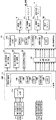
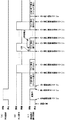
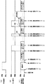
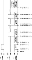
パチンコ遊技機1には、例えば図2に示すような主基板11、演出制御基板12、音声制御基板13、ランプ制御基板14といった、各種の制御基板が搭載されている。また、パチンコ遊技機1には、主基板11と演出制御基板12との間で伝送される各種の制御信号を中継するための中継基板15なども搭載されている。その他にも、パチンコ遊技機1における遊技盤2などの背面には、例えば払出制御基板、情報端子基板、発射制御基板、インタフェース基板などといった、各種の基板が配置されている。
Various control boards such as a
主基板11は、メイン側の制御基板であり、パチンコ遊技機1における遊技の進行を制御するための各種回路が搭載されている。主基板11は、主として、特図ゲームにおいて用いる乱数の設定機能、所定位置に配設されたスイッチ等からの信号の入力を行う機能、演出制御基板12などからなるサブ側の制御基板に宛てて、指令情報の一例となる制御コマンドを制御信号として出力して送信する機能、ホールの管理コンピュータに対して各種情報を出力する機能などを備えている。また、主基板11は、第1特別図柄表示装置4Aと第2特別図柄表示装置4Bを構成する各LED(例えばセグメントLED)などの点灯/消灯制御を行って第1特図や第2特図の可変表示を制御することや、普通図柄表示器20の点灯/消灯/発色制御などを行って普通図柄表示器20による普通図柄の可変表示を制御することといった、所定の表示図柄の可変表示を制御する機能も備えている。主基板11には、例えば遊技制御用マイクロコンピュータ100や、遊技球検出用の各種スイッチからの検出信号を取り込んで遊技制御用マイクロコンピュータ100に伝送するスイッチ回路110などが搭載されている。
The
演出制御基板12は、主基板11とは独立したサブ側の制御基板であり、中継基板15を介して主基板11から伝送された制御信号を受信して、画像表示装置5、スピーカ8L、8R及び遊技効果ランプ9といった演出用の電気部品による演出動作を制御するための各種回路が搭載されている。すなわち、演出制御基板12は、画像表示装置5における表示動作や、スピーカ8L、8Rからの音声出力動作の全部または一部、遊技効果ランプ9などにおける点灯/消灯動作の全部または一部といった、演出用の電気部品に所定の演出動作を実行させるための制御内容を決定する機能を備えている。
The
音声制御基板13は、演出制御基板12とは別個に設けられた音声出力制御用の制御基板であり、演出制御基板12からの指令や制御データなどに基づき、スピーカ8L、8Rから音声を出力させるための音声信号処理を実行する処理回路などが搭載されている。ランプ制御基板14は、演出制御基板12とは別個に設けられたランプ出力制御用の制御基板であり、演出制御基板12からの指令や制御データなどに基づき、遊技効果ランプ9などにおける点灯/消灯駆動を行うランプドライバ回路などが搭載されている。
The
図2に示すように、主基板11には、ゲートスイッチ21、第1始動口スイッチ22A、第2始動口スイッチ22B及びカウントスイッチ23からの検出信号を伝送する配線が接続されている。なお、ゲートスイッチ21、第1始動口スイッチ22A、第2始動口スイッチ22B及びカウントスイッチ23は、例えばセンサと称されるものなどのように、遊技媒体としての遊技球を検出できる任意の構成を有するものであればよい。また、主基板11には、第1特別図柄表示装置4Aや第2特別図柄表示装置4B、普通図柄表示器20などの表示制御を行うための指令信号を伝送する配線が接続されている。
As shown in FIG. 2, wiring for transmitting detection signals from the
主基板11から演出制御基板12に向けて伝送される制御信号は、中継基板15によって中継される。主基板11には、例えば中継基板15に対応する主基板側コネクタが設けられ、主基板側コネクタと遊技制御用マイクロコンピュータ100との間には、出力バッファ回路が接続されている。出力バッファ回路は、主基板11から中継基板15を介して演出制御基板12へ向かう方向にのみ信号を通過させることができ、中継基板15から主基板11への信号の入力を阻止する。したがって、演出制御基板12や中継基板15の側から主基板11側に信号が伝わる余地はない。
A control signal transmitted from the
中継基板15には、例えば主基板11から演出制御基板12に対して制御信号を伝送するための配線毎に、伝送方向規制回路が設けられていればよい。各伝送方向規制回路は、主基板11対応の主基板用コネクタにアノードが接続されるとともに演出制御基板12対応の演出制御基板用コネクタにカソードが接続されたダイオードと、一端がダイオードのカソードに接続されるとともに他端がグランド(GND)接続された抵抗とから構成されている。この構成により、各伝送方向規制回路は、演出制御基板12から中継基板15への信号の入力を阻止して、主基板11から演出制御基板12へ向かう方向にのみ信号を通過させることができる。したがって、演出制御基板12の側から主基板11側に信号が伝わる余地はない。この実施の形態では、中継基板15において制御信号を伝送するための配線毎に伝送方向規制回路を設けるとともに、主基板11にて遊技制御用マイクロコンピュータ100と主基板側コネクタの間に出力バッファ回路を設けることで、外部から主基板11への不正な信号の入力を防止することができる。
The
中継基板15を介して主基板11から演出制御基板12に対して伝送される制御コマンドは、例えば電気信号として送受信される演出制御コマンドである。演出制御コマンドには、例えば画像表示装置5における画像表示動作を制御するために用いられる表示制御コマンドや、スピーカ8L、8Rからの音声出力を制御するために用いられる音声制御コマンド、遊技効果ランプ9や装飾用LEDの点灯動作などを制御するために用いられるランプ制御コマンドが含まれている。図3(A)は、この実施の形態で用いられる演出制御コマンドの内容の一例を示す説明図である。演出制御コマンドは、例えば2バイト構成であり、1バイト目はMODE(コマンドの分類)を示し、2バイト目はEXT(コマンドの種類)を表す。MODEデータの先頭ビット(ビット7)は必ず「1」とされ、EXTデータの先頭ビットは「0」とされる。なお、図3(A)に示されたコマンド形態は一例であって、他のコマンド形態を用いてもよい。また、この例では、制御コマンドが2つの制御信号で構成されることになるが、制御コマンドを構成する制御信号数は、1であってもよいし、3以上の複数であってもよい。
The control command transmitted from the
図3(A)に示す例において、コマンド8001Hは、第1特別図柄表示装置4Aによる特図ゲームにおける第1特図の変動開始を指定する第1変動開始コマンドである。コマンド8002Hは、第2特別図柄表示装置4Bによる特図ゲームにおける第2特図の変動開始を指定する第2変動開始コマンドである。
In the example shown in FIG. 3A, the command 8001H is a first change start command for designating the start of change of the first special figure in the special figure game by the first special symbol display device 4A. The command 8002H is a second change start command for designating the start of change of the second special figure in the special figure game by the second special
コマンド81XXHは、特図ゲームにおける特別図柄の可変表示に対応して画像表示装置5における「左」、「中」、「右」の各飾り図柄表示部5L、5C、5Rで可変表示される飾り図柄などの変動パターンを指定する変動パターン指定コマンドである。ここで、XXHは不特定の16進数であることを示し、演出制御コマンドによる指示内容に応じて任意に設定される値であればよい。変動パターン指定コマンドでは、指定する変動パターンなどに応じて、異なるEXTデータが設定される。なお、変動パターン指定コマンドにおけるEXTデータは、変動パターン指定データともいう。
The command 81XXH is a decoration that is variably displayed on the “left”, “middle”, and “right” decorative
コマンド8CXXHは、特別図柄や飾り図柄などの可変表示結果を指定する可変表示結果通知コマンドである。可変表示結果通知コマンドでは、例えば図3(B)に示すように、可変表示結果が「大当り」となって大当り遊技状態に制御するか否かの事前判定結果、また、可変表示結果が「大当り」となる場合における大当り種別が複数種類のいずれとなるかの大当り種別決定結果に対応して、異なるEXTデータが設定される。より具体的には、コマンド8C00Hは、可変表示結果が「ハズレ」となる旨の事前判定結果を示す第1可変表示結果通知コマンドである。コマンド8C01Hは、可変表示結果が「大当り」で大当り種別SP1となる旨の事前判定結果及び大当り種別決定結果を示す第2可変表示結果通知コマンドである。コマンド8C02Hは、可変表示結果が「大当り」で大当り種別SP2となる旨の事前判定結果及び大当り種別決定結果を示す第3可変表示結果通知コマンドである。コマンド8C03Hは、可変表示結果が「大当り」で大当り種別SP3となる旨の事前判定結果及び大当り種別決定結果を示す第4可変表示結果通知コマンドである。コマンド8C04Hは、可変表示結果が「大当り」で大当り種別SP4となる旨の事前判定結果及び大当り種別決定結果を示す第5可変表示結果通知コマンドである。なお、可変表示結果通知コマンドにおけるEXTデータは、可変表示結果指定データともいう。 The command 8CXXH is a variable display result notification command for designating a variable display result such as a special symbol or a decorative symbol. In the variable display result notification command, for example, as shown in FIG. 3B, the result of prior determination as to whether or not the variable display result is “big hit” and the game is controlled to the big hit gaming state. EXT data is set corresponding to the jackpot type determination result indicating whether the jackpot type is a plurality of types. More specifically, the command 8C00H is a first variable display result notification command indicating a prior determination result indicating that the variable display result is “lost”. The command 8C01H is a second variable display result notification command indicating a prior determination result that the variable display result is “big hit” and the big hit type SP1 and the big hit type determination result. The command 8C02H is a third variable display result notification command indicating a prior determination result indicating that the variable display result is “big hit” and the big hit type SP2 and the big hit type determination result. The command 8C03H is a fourth variable display result notification command indicating a prior determination result indicating that the variable display result is “big hit” and the big hit type SP3 and the big hit type determination result. The command 8C04H is a fifth variable display result notification command indicating a prior determination result that the variable display result is “big hit” and the big hit type SP4 and the big hit type determination result. The EXT data in the variable display result notification command is also referred to as variable display result designation data.
この実施の形態では、変動パターン指定コマンドと可変表示結果通知コマンドとを、互いに別個の演出制御コマンドとして用意している。これに対して、変動パターン指定コマンドに示される変動パターンと、可変表示結果通知コマンドに示される可変表示結果とを、1つの演出制御コマンドにより特定可能となるように構成してもよい。一例として、変動パターンと可変表示結果(「ハズレ」および「大当り」のいずれかと、「大当り」となる場合における大当り種別)との組合せに対応してEXTデータが設定される演出制御コマンドを用意して、その演出制御コマンドにより、変動パターンと可変表示結果を特定可能な情報が伝送されるようにしてもよい。あるいは、3つ以上の演出制御コマンドにより、変動パターンと可変表示結果とを特定できるようにしてもよい。 In this embodiment, the variation pattern designation command and the variable display result notification command are prepared as separate presentation control commands. On the other hand, the variation pattern indicated in the variation pattern designation command and the variable display result indicated in the variable display result notification command may be configured to be specified by one effect control command. As an example, an effect control command for setting EXT data corresponding to a combination of a variation pattern and a variable display result (one of “losing” and “big hit” and a big hit type in the case of “big hit”) is prepared. Then, information that can specify the variation pattern and the variable display result may be transmitted by the effect control command. Alternatively, the variation pattern and the variable display result may be specified by three or more effect control commands.
コマンド8F00Hは、画像表示装置5における「左」、「中」、「右」の各飾り図柄表示エリア5L、5C、5Rで飾り図柄の可変表示の停止を指定する飾り図柄停止コマンドである。なお、飾り図柄停止コマンドは、主基板11から演出制御基板12に対して伝送されないようにしてもよい。この場合には、変動パターン指定コマンドで指定された変動パターンに対応する可変表示時間を、演出制御基板12の側で特定し、飾り図柄の可変表示を開始してからの経過時間が可変表示時間に達したときに、主基板11からの演出制御コマンドを受信しなくても、確定飾り図柄を完全停止表示して可変表示結果を確定させるようにしてもよい。
The command 8F00H is a decorative symbol stop command for designating stop of variable display of decorative symbols in the “left”, “middle”, and “right” decorative
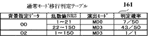
コマンド90XXHは、パチンコ遊技機1における遊技状態に応じた背景画像の表示を指定する背景指定コマンドである。背景指定コマンドでは、例えば図3(C)に示すように、パチンコ遊技機1における遊技状態が低確低ベース状態といった通常状態であるか、あるいは、低確高ベース状態、高確低ベース状態、高確高ベース状態といった複数種類の特別遊技状態のいずれであるかに応じて、異なるEXTデータが設定される。より具体的には、コマンド9000Hは、遊技状態が低確低ベース状態であるときに伝送される第1背景指定コマンドである。コマンド9001Hは、遊技状態が低確高ベース状態であるときに伝送される第2背景指定コマンドである。コマンド9002Hは、遊技状態が高確低ベース状態であるときに伝送される第3背景指定コマンドである。コマンド9003Hは、遊技状態が高確高ベース状態であるときに伝送される第4背景指定コマンドである。この実施の形態では、特別図柄や飾り図柄の可変表示が開始されるときと、デモ画面の表示が指定されるときに、背景指定コマンドが主基板11から演出制御基板12に対して伝送されればよい。なお、背景指定コマンドにおけるEXTデータは、背景指定データともいう。
The command 90XXH is a background designation command for designating display of a background image corresponding to the gaming state in the
コマンドA0XXHは、大当り遊技状態の開始を指定する当り開始指定コマンド(「ファンファーレコマンド」ともいう)である。当り開始指定コマンドでは、大当り遊技状態が開始される契機となった特図ゲームなどにおける大当り種別が複数種類の大当り種別SP1〜大当り種別SP4のいずれであるかに応じて、異なるEXTデータが設定される。一例として、当り開始指定コマンドでは、可変表示結果通知コマンドと同様のEXTデータが設定されることなどにより、事前判定結果や大当り種別決定結果に応じて異なるEXTデータが設定されてもよい。あるいは、当り開始指定コマンドでは、事前判定結果及び大当り種別決定結果と、設定されるEXTデータとの対応関係を、可変表示結果通知コマンドにおける対応関係とは異ならせるようにしてもよい。なお、当り開始指定コマンドにおけるEXTデータは、開始指定データともいう。 The command A0XXH is a hit start designation command (also referred to as a “fanfare command”) that designates the start of the big hit gaming state. In the hit start designation command, different EXT data is set depending on which of the big hit types SP1 to SP4 is the big hit type in the special figure game or the like that triggered the big hit gaming state. The As an example, in the hit start designation command, EXT data similar to that of the variable display result notification command may be set, so that different EXT data may be set according to the prior determination result or the big hit type determination result. Alternatively, in the hit start designation command, the correspondence relationship between the preliminary determination result and the big hit type determination result and the set EXT data may be different from the correspondence relationship in the variable display result notification command. The EXT data in the hit start designation command is also referred to as start designation data.
コマンドA1XXHは、大当り遊技状態におけるラウンドの実行回数に対応して、各ラウンドで大入賞口が開放状態となっている期間における演出画像の表示を指定する大入賞口開放中指定コマンドである。コマンドA2XXHは、大当り遊技状態におけるラウンドの実行回数に対応して、各ラウンドの終了により大入賞口が閉鎖状態に変化してから次回のラウンドにて大入賞口が開放状態となるまでの期間(インターバル期間)における演出画像の表示を指定する大入賞口開放後指定コマンドである。大入賞口開放中指定コマンドや大入賞口開放後指定コマンドでは、例えば大当り遊技状態におけるラウンドの実行回数(例えば「1」〜「15」)に応じて、異なるEXTデータが設定される。なお、大当り遊技状態では、各ラウンドで大入賞口が開放状態となっている期間であるか、各ラウンドの終了により大入賞口が開放状態から閉鎖状態に変化した期間であるかにかかわりなく、大当り遊技状態の開始時点から終了時点まで継続的な演出動作が実行されるようにしてもよい。 The command A1XXH is a special prize opening opening designation command that designates display of an effect image during a period in which the big prize opening is open in each round, corresponding to the number of rounds executed in the big hit gaming state. The command A2XXH corresponds to the number of executions of the round in the big hit gaming state, and the period (from the end of each round to the closing state of the big winning opening being closed to the opening of the big winning opening in the next round ( This is a designation command after opening the big prize opening that designates display of the effect image in the interval period). In the special winning opening opening designation command and the special winning opening open designation command, different EXT data is set according to, for example, the number of round executions (for example, “1” to “15”) in the big hit gaming state. In the big hit gaming state, regardless of whether it is a period in which the big prize opening is in an open state in each round or a period in which the big prize opening is changed from an open state to a closed state at the end of each round, A continuous performance operation may be executed from the start time to the end time of the big hit gaming state.
コマンドA3XXHは、大当り遊技状態の終了を指定する当り終了指定コマンドである。当り終了指定コマンドでは、例えば図3(D)に示すように、大当り遊技状態が開始される契機となった特図ゲームなどにおける大当り種別が複数種類の大当り種別SP1〜大当り種別SP4のいずれであるかに応じて、異なるEXTデータが設定される。より具体的には、コマンドA300Hは、大当り種別決定結果が大当り種別SP1であったことを示す第1当り終了指定コマンドである。コマンドA301Hは、大当り種別決定結果が大当り種別SP2であったことを示す第2当り終了指定コマンドである。コマンドA302Hは、大当り種別決定結果が大当り種別SP3であったことを示す第3当り終了指定コマンドである。コマンドA303Hは、大当り種別決定結果が大当り種別SP4であったことを示す第4当り終了指定コマンドである。なお、当り終了指定コマンドにおけるEXTデータは、終了指定データともいう。 The command A3XXH is a hit end specifying command for specifying the end of the big hit gaming state. In the hit end designation command, for example, as shown in FIG. 3D, the big hit type in the special game that triggered the big hit gaming state is any one of a plurality of types of big hit types SP1 to big hit type SP4. Accordingly, different EXT data is set. More specifically, the command A300H is a first hit end designation command indicating that the jackpot type determination result is the jackpot type SP1. Command A301H is a second hit end designation command indicating that the jackpot type determination result is jackpot type SP2. Command A302H is a third hit end designation command indicating that the jackpot type determination result is jackpot type SP3. Command A303H is a fourth hit end designation command indicating that the jackpot type determination result is jackpot type SP4. The EXT data in the hit end specifying command is also referred to as end specifying data.
コマンドB001Hは、普通入賞球装置6Aが形成する第1始動入賞口に遊技球が入賞したことに基づき、第1特別図柄表示装置4Aによる第1特図を用いた特図ゲームを実行するための第1始動条件が成立したことを通知する第1始動口入賞指定コマンドである。コマンドB002Hは、普通可変入賞球装置6Bが形成する第2始動入賞口に遊技球が入賞したことに基づき、第2特別図柄表示装置4Bによる第2特図を用いた特図ゲームを実行するための第2始動条件が成立したことを通知する第2始動口入賞指定コマンドである。
The command B001H is for executing a special game using the first special figure by the first special symbol display device 4A based on the fact that the game ball has won the first start winning opening formed by the normal
コマンドC0XXHは、画像表示装置5に設けられた始動入賞記憶表示部5Hなどにて特図保留記憶数を特定可能に表示するために、第1保留記憶数と第2保留記憶数との合計値である合計保留記憶数を通知する保留記憶数通知コマンドである。保留記憶数通知コマンドは、例えば第1始動条件と第2始動条件のいずれかが成立したことに対応して、第1始動口入賞指定コマンドと第2始動口入賞指定コマンドのいずれかが送信されたことに続いて、主基板11から演出制御基板12に対して伝送される。また、保留記憶数通知コマンドは、特別図柄や飾り図柄の可変表示が開始されるときにも、主基板11から演出制御基板12に対して伝送される。保留記憶数通知コマンドでは、例えば図12に示す第1特図保留記憶部151Aにおける保留データと第2特図保留記憶部151Bにおける保留データの総記憶数(例えば「1」〜「8」)、あるいは、始動データ記憶部151Cにおける始動データの総記憶数(例えば「1」〜「8」)に応じて、異なるEXTデータが設定される。これにより、演出制御基板12の側では、第1始動条件と第2始動条件のいずれかが成立したときに、主基板11から伝送された保留記憶数通知コマンドを受信して、第1特図保留記憶部151Aと第2特図保留記憶部151Bにおける保留データの総記憶数を特定することができる。なお、保留記憶数通知コマンドにおけるEXTデータは、保留記憶数指定データともいう。
The command C0XXH is a total value of the first reserved memory number and the second reserved memory number so that the special figure reserved memory number can be specified on the start winning memory display unit 5H provided in the
主基板11に搭載された遊技制御用マイクロコンピュータ100は、例えば1チップのマイクロコンピュータであり、ゲーム制御用のプログラムや固定データ等を記憶するROM(Read Only Memory)101と、ゲーム制御用のワークエリアを提供するRAM(Random Access Memory)102と、プログラムに従って制御動作を行うCPU(Central Processing Unit)103と、CPU103とは独立して乱数値を示す数値データの更新を行う乱数回路104と、I/O(Input/Output port)105とを備えて構成される。一例として、遊技制御用マイクロコンピュータ100では、CPU103がROM101から読み出したプログラムを実行することにより、パチンコ遊技機1における遊技の進行を制御するための処理が実行される。このときには、CPU103がROM101から固定データを読み出す固定データ読出動作や、CPU103がRAM102に各種の変動データを書き込んで一時記憶させる変動データ書込動作、CPU103がRAM102に一時記憶されている各種の変動データを読み出す変動データ読出動作、CPU103がI/O105を介して遊技制御用マイクロコンピュータ100の外部から各種信号の入力を受け付ける受信動作、CPU103がI/O105を介して遊技制御用マイクロコンピュータ100の外部へと各種信号を出力する送信動作なども行われる。
The
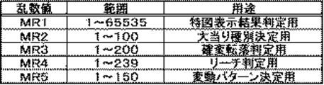
主基板11では、例えば図2に示す遊技制御用マイクロコンピュータ100が備える乱数回路104などにより、遊技の進行を制御するために用いられる各種の乱数値を示す数値データが更新可能にカウントされる。図4は、主基板11の側においてカウントされる乱数値を例示する説明図である。図4に示すように、この実施の形態では、主基板11の側において、特図表示結果判定用の乱数値MR1、大当り種別決定用の乱数値MR2、確変転落判定用の乱数値MR3、リーチ判定用の乱数値MR4、変動パターン決定用の乱数値MR5のそれぞれを示す数値データが、カウント可能に制御される。なお、遊技効果を高めるために、これら以外の乱数値が用いられてもよい。乱数回路104は、これらの乱数値MR1〜MR5の全部または一部を示す数値データをカウントするものであればよい。CPU103は、例えば図12に示す遊技制御カウンタ設定部154に設けられたランダムカウンタといった、乱数回路104とは異なるランダムカウンタを用いて、ソフトウェアによって各種の数値データを更新することで、乱数値MR1〜MR5の一部を示す数値データをカウントするようにしてもよい。一例として、特図表示結果判定用の乱数値MR1を示す数値データは、乱数回路104によりCPU103とは独立して更新され、それ以外の乱数値MR2〜MR5を示す数値データは、CPU103がランダムカウンタを用いてソフトウェアにより更新されればよい。乱数回路104は、遊技制御用マイクロコンピュータ100に内蔵されるものであってもよいし、遊技制御用マイクロコンピュータ100とは異なる乱数回路チップとして構成されるものであってもよい。
On the
特図表示結果判定用の乱数値MR1は、特図ゲームにおける特別図柄などの可変表示結果を「大当り」として大当り遊技状態に制御するか否かを判定するために用いられる乱数値である。例えば、特図表示結果決定用の乱数値MR1は、「1」〜「65535」の範囲の値をとる。大当り種別決定用の乱数値MR2は、可変表示結果を「大当り」とする場合に、大当り種別を複数種類のいずれかに決定するために用いられる乱数値である。例えば、大当り種別決定用の乱数値MR2は、「1」〜「100」の範囲の値をとる。 The random number value MR1 for determining the special figure display result is a random value used for determining whether or not to control the big hit gaming state with the variable display result of the special symbol or the like in the special figure game as “big hit”. For example, the random number value MR1 for determining the special figure display result takes a value in the range of “1” to “65535”. The random value MR2 for determining the big hit type is a random value used for determining the big hit type as one of a plurality of types when the variable display result is “big hit”. For example, the random value MR2 for determining the jackpot type takes a value in the range of “1” to “100”.
確変転落判定用の乱数値MR3は、確変制御を終了させるか否かの確変転落判定に用いられる乱数値である。例えば、確変転落判定用の乱数値MR3は、「1」〜「200」の範囲の値をとる。リーチ判定用の乱数値MR4は、可変表示結果を「ハズレ」とする場合に、飾り図柄の可変表示状態をリーチ表示状態とするか否かを判定するために用いられる乱数値である。例えば、リーチ判定用の乱数値MR4は、「1」〜「239」の範囲の値をとる。変動パターン決定用の乱数値MR5は、飾り図柄の変動パターンを、予め用意された複数種類のいずれかに決定するために用いられる乱数値である。例えば、変動パターン決定用の乱数値MR5は、「1」〜「150」の範囲の値をとる。 The random number MR3 for the probability variation fall determination is a random value used for the probability variation fall determination as to whether or not to end the probability variation control. For example, the random value MR3 for probability variation fall determination takes a value in the range of “1” to “200”. The reach determination random value MR4 is a random value used for determining whether or not the variable display state of the decorative symbol is set to the reach display state when the variable display result is “lost”. For example, the random number MR4 for reach determination takes a value in the range of “1” to “239”. The random number value MR5 for determining the variation pattern is a random value used for determining the variation pattern of the decorative design as one of a plurality of types prepared in advance. For example, the random number MR5 for determining the variation pattern takes a value in the range of “1” to “150”.
図2に示す遊技制御用マイクロコンピュータ100が備えるROM101には、ゲーム制御用のプログラムの他にも、遊技の進行を制御するために用いられる各種のデータテーブルなどが格納されている。例えば、ROM101には、CPU103が各種の判定や決定、設定を行うために用意された複数の判定テーブルや決定テーブル、設定テーブルをそれぞれ構成するテーブルデータが、記憶されている。また、ROM101には、CPU103が主基板11から各種の制御コマンドとなる制御信号を送信するために用いられる複数のコマンドテーブルをそれぞれ構成するテーブルデータや、飾り図柄の変動パターンを複数種類格納する変動パターンテーブルを構成するテーブルデータなどが、記憶されている。
In addition to the game control program, the
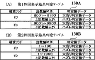
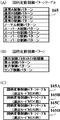
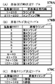
図5は、ROM101に記憶される特図表示結果判定テーブルの構成例を示している。この実施の形態では、特図表示結果判定テーブルとして、図5(A)に示す第1特図表示結果判定テーブル130Aと、図5(B)に示す第2特図表示結果判定テーブル130Bとが、予め用意されている。第1特図表示結果判定テーブル130Aは、第1特別図柄表示装置4Aによる第1特図を用いた特図ゲームにおいて可変表示結果となる確定特別図柄が導出表示される以前に、その可変表示結果を「大当り」として大当り遊技状態に制御するか否かを、特図表示結果判定用の乱数値MR1に基づいて判定するために参照されるテーブルである。第2特図表示結果判定テーブル130Bは、第2特別図柄表示装置4Bによる第2特図を用いた特図ゲームにおいて可変表示結果となる確定特別図柄が導出表示される以前に、その可変表示結果を「大当り」として大当り遊技状態に制御するか否かを、特図表示結果判定用の乱数値MR1に基づいて判定するために参照されるテーブルである。
FIG. 5 shows a configuration example of a special figure display result determination table stored in the
第1特図表示結果判定テーブル130Aと第2特図表示結果判定テーブル130Bのそれぞれでは、図12に示す遊技制御フラグ設定部152に設けられた確変フラグがオフであるかオンであるかに応じて、特図表示結果判定用の乱数値MR1が、大当り判定値データやハズレ判定値データと対応付けられるように、割り振られている。第1特図表示結果判定テーブル130Aや第2特別図柄表示結果判定テーブル130Bにおいて特図表示結果判定用の乱数値MR1を示すテーブルデータは、大当り遊技状態に制御するか否かの判定結果に割り振られる判定用データとなっている。そして、第1特図表示結果判定テーブル130Aと第2特図表示結果判定テーブル130Bのそれぞれでは、確変フラグがオンであるときには、確変フラグがオフであるときに比べて多くの乱数値MR1が、大当り決定値データに割り振られている。ここで、高確低ベース状態や高確高ベース状態といった、高確状態を含んだ遊技状態であるときには、確変フラグがオンとなる。その一方で、低確低ベース状態や低確高ベース状態といった、低確状態を含んだ遊技状態であるときには、確変フラグがオフとなる。これにより、高確状態を含んだ遊技状態であるときには、低確状態を含んだ遊技状態であるときに比べて、可変表示結果を「大当り」として大当り遊技状態に制御すると判定される確率が高くなる。すなわち、第1特図表示結果判定テーブル130Aと第2特図表示結果判定テーブル130Bのそれぞれでは、高確状態を含んだ遊技状態であるときに、低確状態を含んだ遊技状態であるときに比べて大当り遊技状態に制御すると判定される確率が高くなるように、判定用データが大当り遊技状態に制御するか否かの判定結果に割り振られている。
In each of the first special figure display result determination table 130A and the second special figure display result determination table 130B, depending on whether the probability change flag provided in the game control
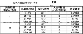
図6は、ROM101に記憶される大当り種別決定テーブル131の構成例を示している。大当り種別決定テーブル131は、可変表示結果を「大当り」として大当り遊技状態に制御すると決定されたときに、大当り種別決定用の乱数値MR2に基づき、大当り種別を複数種類のいずれかに決定するために参照されるテーブルである。大当り種別決定テーブル131は、図12に示す遊技制御バッファ設定部155に設けられた変動特図指定バッファの値(変動特図指定バッファ値)が「1」であるか「2」であるかに応じて、大当り種別決定用の乱数値MR2が、大当り種別SP1〜大当り種別SP4に割り振られている。ここで、変動特図指定バッファ値は、第1開始条件の成立により第1特別図柄表示装置4Aにて第1特図を用いた特図ゲームを開始するときに「1」が設定される一方で、第2開始条件の成立により第2特別図柄表示装置4Bにて第2特図を用いた特図ゲームを開始するときに「2」が設定される。この実施の形態では、大当り種別SP1〜大当り種別SP4のいずれであるかに応じて、複数種類の大当り図柄のいずれかが、特図ゲームにおける可変表示結果としての確定特別図柄となる。すなわち、大当り種別決定テーブル131において大当り種別決定用の乱数値MR2を示すテーブルデータは、複数種類の大当り種別に対応した複数種類の大当り図柄に割り振られる決定用データとなっている。また、大当り種別決定テーブル131は、遊技制御バッファ設定部155に設けられた大当り種別バッファの値(大当り種別バッファ値)を、大当り種別決定用の乱数値MR2に基づいて決定された大当り種別に対応して、「1」〜「4」のいずれかに設定するためのテーブルデータ(設定用データ)を含んでいる。
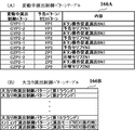
FIG. 6 shows a configuration example of the jackpot type determination table 131 stored in the
図6に示す大当り種別決定テーブル131の設定では、変動特図指定バッファ値が「1」であるか「2」であるかに応じて、大当り種別SP1〜大当り種別SP4のそれぞれに対する大当り種別決定用の乱数値MR2の割り振りが異なっている。そのため、第1特別図柄表示装置4Aによる第1特図を用いた特図ゲームを開始するための第1開始条件が成立したことに基づいて大当り種別を複数種類のいずれかに決定するときと、第2特別図柄表示装置4Bによる第2特図を用いた特図ゲームを開始するための第2開始条件が成立したことに基づいて大当り種別を複数種類のいずれかに決定するときとでは、各大当り種別の決定確率が異なるものとなる。こうした設定により、第1開始条件と第2開始条件のいずれが成立したかに応じて、大当り図柄の種類である大当り種別の決定確率を、異ならせることができる。また、図6に示す大当り種別決定テーブル131において、大当り種別SP1の決定確率は、大当り種別SP2の決定確率に比べて、同等か高くなるように設定されている。その一方で、大当り種別SP3の決定確率は、大当り種別SP4の決定確率に比べて、低くなるように設定されている。
In the setting of the jackpot type determination table 131 shown in FIG. 6, the jackpot type determination for each of the jackpot type SP1 to the jackpot type SP4 depending on whether the variable special figure designation buffer value is “1” or “2”. The random number MR2 is assigned differently. Therefore, when the jackpot type is determined as one of a plurality of types based on the establishment of the first start condition for starting the special figure game using the first special figure by the first special symbol display device 4A, When determining the jackpot type as one of a plurality of types based on the fact that the second start condition for starting the special figure game using the second special figure by the second special
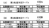
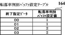
図7は、ROM101に記憶される確変転落判定テーブルの構成例を示している。この実施の形態では、確変転落判定テーブルとして、図7(A)に示す第1転落判定テーブル132Aと、図7(B)に示す第2転落判定テーブル132Bとが、予め用意されている。第1転落判定テーブル132Aは、図12に示す遊技制御バッファ設定部155に設けられた転落率指定バッファの値(転落率指定バッファ値)が「1」であるときに、高確低ベース状態や高確高ベース状態といった高確状態を含む遊技状態における確変制御を終了するか否かを、確変転落判定用の乱数値MR3に基づいて判定するために参照されるテーブルである。第2転落判定テーブル132Bは、転落率指定バッファ値が「2」であるときに、確変制御を終了するか否かを、確変転落判定用の乱数値MR3に基づいて判定するために参照されるテーブルである。
FIG. 7 shows an example of the structure of the probability variation fall determination table stored in the
第1転落判定テーブル132Aと第2転落判定テーブル132Bのそれぞれでは、確変転落判定用の乱数値MR3が、転落判定値データや継続判定値データと対応付けられるように、割り振られている。第1転落判定テーブル132Aや第2転落判定テーブル132Bにおいて確変転落判定用の乱数値MR3を示すテーブルデータは、確変制御を終了するか否かの判定結果に割り振られる判定用データとなっている。そして、第1転落判定テーブル132Aでは、第2転落判定テーブル132Bに比べて多くの乱数値MR3が、継続判定値データに割り振られている。これにより、転落率指定バッファ値が「1」であるときには、転落率指定バッファ値が「2」であるときに比べて、確変制御を終了せずに継続すると判定される確率が高くなる。すなわち、第1転落判定テーブル132Aと第2転落判定テーブル132Bでは、転落率指定バッファ値が「1」であるか「2」であるかに応じて、確変制御を終了すると判定される終了判定確率が異なるように、判定用データが確変制御を終了するか否かの判定結果に割り振られている。図7(A)に示す例では、第1転落判定テーブル132Aを参照して確変転落判定を行うときに、終了判定確率が1/100となる。これに対して、図7(B)に示す例では、第2転落判定テーブル132Bを参照して確変転落判定を行うときに、終了判定確率が1/5となる。 In each of the first fall determination table 132A and the second fall determination table 132B, the random value MR3 for probability variation fall determination is assigned so as to be associated with the fall determination value data and the continuation determination value data. In the first fall determination table 132A and the second fall determination table 132B, the table data indicating the random number MR3 for probability variation fall determination is data for determination that is assigned to the determination result as to whether or not the probability variation control is to be ended. In the first drop determination table 132A, more random number values MR3 are assigned to the continuation determination value data than in the second drop determination table 132B. Thereby, when the fall rate designation buffer value is “1”, the probability that it is determined to continue without ending the probability variation control is higher than when the fall rate designation buffer value is “2”. That is, in the first fall determination table 132A and the second fall determination table 132B, the end determination probability determined to end the probability variation control depending on whether the fall rate designation buffer value is “1” or “2”. Are different from each other, the determination data is allocated to the determination result as to whether or not to end the probability variation control. In the example shown in FIG. 7A, the end determination probability is 1/100 when the probability change fall determination is performed with reference to the first fall determination table 132A. On the other hand, in the example shown in FIG. 7B, when the probability variation fall determination is performed with reference to the second fall determination table 132B, the end determination probability becomes 1/5.
なお、第1開始条件と第2開始条件のいずれが成立したかに応じて、確変制御を終了すると判定される確率を異ならせるようにしてもよい。この場合には、確変転落判定テーブルにおいて、転落判定値データや継続判定値データに対する乱数値MR3の割り振りを、変動特図指定バッファ値に応じて異ならせればよい。一例として、変動特図指定バッファ値が「1」のときに参照される判定用データでは、変動特図指定バッファ値が「2」のときに参照される判定用データに比べて、多くの乱数値MR3が継続判定値データに割り振られるように構成されてもよい。このような設定によれば、第1開始条件が成立したときには、第2開始条件が成立したときに比べて、確変制御を終了せずに継続すると判定される確率が高くなる。 Note that the probability of determining that the probability variation control is to be ended may be varied depending on which of the first start condition and the second start condition is satisfied. In this case, in the probability variation fall determination table, the allocation of the random number MR3 to the fall determination value data and the continuation determination value data may be made different according to the variation special figure designation buffer value. As an example, the determination data referred to when the variation special figure designation buffer value is “1” has more disturbances than the determination data referred to when the variation special figure designation buffer value is “2”. The numerical value MR3 may be configured to be assigned to the continuation determination value data. According to such setting, when the first start condition is satisfied, the probability that it is determined to continue without ending the probability variation control is higher than when the second start condition is satisfied.
図8は、ROM101に記憶されるリーチ判定テーブル133の構成例を示している。リーチ判定テーブル133は、可変表示結果を「ハズレ」として大当り遊技状態に制御しないと判定されたときに、飾り図柄の可変表示状態をリーチ表示状態とするか否かを、リーチ判定用の乱数値MR4に基づいて判定するために参照されるテーブルである。リーチ判定テーブル133では、合計保留記憶数が「0」、「1」、「2」、「3」または「4」、「5」〜「8」のいずれであるかに応じて、リーチ判定用の乱数値MR4が、「非リーチ」あるいは「リーチ」の判定結果に割り振られている。リーチ判定テーブル133の設定では、合計保留記憶数が所定数未満であるときに、合計保留記憶数が所定数以上であるときに比べて多くの乱数値MR4が、「リーチ」の判定結果に割り振られている。一例として、合計保留記憶数が「0」であるときには、乱数値MR4のうち「205」〜「239」の範囲の値が「リーチ」の判定結果に割り振られている。これに対して、合計保留記憶数が「1」であるときには、乱数値MR4のうち「218」〜「239」の範囲の値が「リーチ」の判定結果に割り振られている。このような設定により、合計保留記憶数が所定数以上であるときには、所定数未満であるときに比べて、飾り図柄の可変表示状態をリーチ表示状態にすると判定される確率が低くなる。そして、「非リーチ」に対応した変動パターンにおける特別図柄や飾り図柄の平均的な可変表示時間が「リーチ」に対応した変動パターンにおける平均的な可変表示時間に比べて短くなるように設定されていれば、合計保留記憶数が所定数以上であるときには、所定数未満であるときに比べて、平均的な可変表示時間を短縮することができる。
FIG. 8 shows a configuration example of the reach determination table 133 stored in the
なお、パチンコ遊技機1における遊技状態が複数種類のいずれであるかに応じて、あるいは、第1開始条件と第2開始条件のいずれが成立したかに応じて、リーチ表示状態にすると判定される確率を異ならせるようにしてもよい。この場合には、「非リーチ」や「リーチ」の判定結果に対する乱数値MR4の割り振りが異なる複数のリーチ判定テーブルを用意する。そして、パチンコ遊技機1における遊技状態が複数種類のいずれであるかに応じて、あるいは、第1開始条件と第2開始条件のいずれが成立したかに応じて、異なるリーチ判定テーブルを参照することにより、リーチ表示状態とするか否かを判定すればよい。一例として、高確高ベース状態や低確高ベース状態といった高ベース状態を含む遊技状態であるときには、低ベース状態を含む遊技状態であるときに比べて、リーチ表示状態にすると判定される確率が低くなるように、複数のリーチ判定テーブルが設定(選択)されてもよい。こうして、時短制御が行われる高ベース状態を含む遊技状態であるときには、時短制御が行われない低ベース状態を含む遊技状態であるときに比べて、可変表示結果が「ハズレ」となる場合における平均的な可変表示時間を短縮することが可能になる。
It is determined that the reach display state is set according to which of the plurality of types of gaming states in the
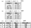
図9は、ROM101に記憶される変動パターン決定テーブルの構成例を示している。この実施の形態では、変動パターン決定テーブルとして、図9(A)に示す大当り変動パターン決定テーブル134Aと、図9(B)に示すリーチハズレ変動パターン決定テーブル134Bと、図9(C)に示す非リーチハズレ変動パターン決定テーブル134Cとが、予め用意されている。大当り変動パターン決定テーブル134Aは、可変表示結果を「大当り」として大当り遊技状態に制御すると判定されたとき(大当り判定時)に、変動パターン決定用の乱数値MR5に基づき、変動パターンを複数種類のいずれかに決定するために参照されるテーブルである。リーチハズレ変動パターン決定テーブル134Bは、可変表示結果を「ハズレ」として大当り遊技状態に制御しないと判定されるとともに、飾り図柄の可変表示状態をリーチ表示状態にすると判定されたとき(リーチハズレ判定時)に、変動パターン決定用の乱数値MR5に基づき、変動パターンを複数種類のいずれかに決定するために参照されるテーブルである。非リーチハズレ変動パターン決定テーブル134Cは、可変表示結果を「ハズレ」として大当り遊技状態に制御しないと判定されるとともに、飾り図柄の可変表示状態をリーチ表示状態にしないと判定されたとき(非リーチハズレ判定時)に、変動パターン決定用の乱数値MR5に基づき、変動パターンを複数種類のいずれかに決定するために参照されるテーブルである。
FIG. 9 shows a configuration example of a variation pattern determination table stored in the
この実施の形態では、大当り判定時に決定され得る変動パターンとして、複数種類の大当り変動パターンとなるリーチパターンが、予め用意されている。また、リーチハズレ判定時に決定され得る変動パターンとして、複数種類のリーチハズレ変動パターンとなるリーチパターンが、予め用意されている。さらに、非リーチハズレ判定時に決定され得る変動パターンとして、複数種類の非リーチハズレ変動パターンとなる非リーチパターンが、予め用意されている。一例として、リーチパターンとなる複数種類の変動パターンには、ノーマル、スーパーA〜スーパーDの変動パターンが含まれている。また、非リーチパターンとなる複数種類の変動パターンには、通常A〜通常Dの変動パターンが含まれている。 In this embodiment, reach patterns that are a plurality of types of big hit fluctuation patterns are prepared in advance as fluctuation patterns that can be determined at the time of jackpot determination. In addition, as a variation pattern that can be determined at the time of reach loss determination, reach patterns that are a plurality of types of reach loss variation patterns are prepared in advance. Further, as the variation patterns that can be determined at the time of non-reach loss determination, non-reach patterns that are a plurality of types of non-reach loss variation patterns are prepared in advance. As an example, a plurality of types of variation patterns serving as reach patterns include normal, super A to super D variation patterns. Further, the plurality of types of variation patterns that are non-reach patterns include a variation pattern of normal A to normal D.
大当り変動パターン決定テーブル134Aと、リーチハズレ変動パターン決定テーブル134Bとを比べると、各リーチパターン(リーチの種類)に対する変動パターン決定用の乱数値MR5の割り振りが異なっている。すなわち、可変表示結果が「大当り」となるか「ハズレ」となるかに応じて、各リーチパターンの決定確率が異なるものとなる。これにより、可変表示結果が「大当り」となる可能性は、飾り図柄の可変表示中にリーチ表示状態となった後に実行されるリーチ演出での演出態様に応じて、異なるものとなる。このように、リーチの種類毎に決められる可変表示結果が「大当り」となる可能性(確率)は、リーチの大当り信頼度、あるいは単に、リーチの信頼度ともいう。ここで、各リーチパターンに対応するリーチの信頼度は、((大当り時における当該可変表示パターンの選択確率)×(大当り確率))/((ハズレ時における当該可変表示パターンの選択確率)×(ハズレ確率)×(リーチ出現率)+(大当り時における当該可変表示パターンの選択確率)×(大当り確率))として求めることができる。なお、(ハズレ確率)=1−(大当り確率)である。 When the big hit variation pattern determination table 134A and the reach loss variation pattern determination table 134B are compared, the allocation of the variation pattern random number MR5 for each reach pattern (reach type) is different. That is, the reach probability of each reach pattern varies depending on whether the variable display result is “big hit” or “lost”. As a result, the possibility that the variable display result will be a “big hit” varies depending on the production mode of the reach effect that is executed after the reach display state during the variable display of the decorative symbol. In this way, the possibility (probability) that the variable display result determined for each type of reach is a “big hit” is also referred to as the reach big hit reliability or simply the reach reliability. Here, the reach reliability corresponding to each reach pattern is ((selection probability of the variable display pattern at the time of big hit) × (probability of big hit)) / ((selection probability of the variable display pattern at the time of loss) × ( Loss probability) × (reach appearance rate) + (selection probability of the variable display pattern at the time of big hit) × (big hit probability)). Note that (loss probability) = 1− (big hit probability).
非リーチハズレ変動パターン決定テーブル134Cでは、図12に示す遊技制御フラグ設定部152に設けられた時短フラグがオフであるかオンであるかに応じて、非リーチパターンに対する乱数値MR5の割り振りが、異なっている。図9(C)に示す例では、時短フラグがオンであるときには、オフであるときに比べて可変表示時間が短い変動パターンに対して、乱数値MR5が割り振られている。ここで、高確高ベース状態や低確高ベース状態といった、高ベース状態を含んだ遊技状態であるときには、時短フラグがオンとなる。その一方で、高確低ベース状態や低確低ベース状態といった、低ベース状態を含んだ遊技状態であるときには、時短フラグがオフとなる。そのため、高ベース状態を含んだ遊技状態であるときには、低ベース状態を含んだ遊技状態であるときに比べて、可変表示時間を短くすることができる。こうした非リーチハズレ変動パターン決定テーブル134Cの設定により、高ベース状態を含んだ遊技状態であるときには、低ベース状態を含んだ遊技状態であるときに比べて可変表示時間を短くする時短制御を行うことができる。
In the non-reach loss variation pattern determination table 134C, the allocation of the random value MR5 to the non-reach pattern differs depending on whether the time reduction flag provided in the game control
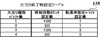
図10は、ROM101に記憶される大当り終了時設定テーブル135の構成例を示している。大当り終了時設定テーブル135は、大当り遊技状態が終了するときに、大当り種別バッファ値に応じて、図12に示す遊技制御カウンタ設定部154に設けられた時短回数カウンタにおけるカウント初期値や、遊技制御バッファ設定部155に設けられた転落率指定バッファにおける値(転落率指定バッファ値)を、設定するために参照されるテーブルである。図10に示すように、大当り終了時設定テーブル135では、大当り種別バッファ値「1」〜「4」が、時短回数カウンタ設定値や転落率指定バッファ設定値と対応付けられている。
FIG. 10 shows a configuration example of the jackpot end setting table 135 stored in the
ここで、転落率指定バッファ値が「1」であるときには、図7(A)に示す第1転落判定テーブル132Aを参照して確変転落判定が行われる。これに対して、転落率指定バッファ値が「2」であるときには、図7(B)に示す第2転落判定テーブル132Bを参照して確変転落判定が行われる。したがって、高確状態を含む遊技状態において確変制御を終了するか否かの終了判定確率は、大当り図柄の種類である大当り種別が複数種類のいずれであるかに応じて異なる設定確率で、複数種類の判定確率のいずれかに設定されることになる。図10に示す例では、大当り種別SP1(図柄番号「7」の大当り図柄)に対応して大当り種別バッファ値が「1」であるときや、大当り種別SP2(図柄番号「5」の大当り図柄)に対応して大当り種別バッファ値が「2」であるときには、1/1(100%)の設定確率で転落率指定バッファ値が「1」に設定されることにより、確変転落判定における終了判定確率が1/100となる。その一方で、大当り種別バッファ値が「1」または「2」であるときには、転落率指定バッファ値が「2」に設定されて終了判定確率が1/5となることはない(設定確率は0%である)。また、大当り種別SP3(図柄番号「4」の大当り図柄)に対応して大当り種別バッファ値が「3」であるときや、大当り種別SP4(図柄番号「2」の大当り図柄)に対応して大当り種別バッファ値が「4」であるときには、転落率指定バッファ値が「1」に設定されて終了判定確率が1/100となることはない(設定確率は0%)である。その一方で、大当り種別バッファ値が「3」または「4」であるときには、1/1(100%)の設定確率で転落率指定バッファ値が「2」に設定されることにより、終了判定確率が1/5となる。 Here, when the fall rate designation buffer value is “1”, the probability change fall determination is performed with reference to the first fall determination table 132A shown in FIG. On the other hand, when the fall rate designation buffer value is “2”, the probability change fall determination is performed with reference to the second fall determination table 132B shown in FIG. Therefore, the end determination probability of whether or not to end the probability variation control in the gaming state including the high probability state is a set probability that is different depending on whether the jackpot type which is the type of the jackpot symbol is a plurality of types, and a plurality of types Is set to one of the determination probabilities. In the example shown in FIG. 10, when the big hit type buffer value is “1” corresponding to the big hit type SP1 (big hit symbol of symbol number “7”), or the big hit type SP2 (big hit symbol of symbol number “5”) When the jackpot type buffer value is “2” corresponding to the above, the fall rate designation buffer value is set to “1” with a setting probability of 1/1 (100%), so that the end determination probability in the probability variation fall determination Becomes 1/100. On the other hand, when the jackpot type buffer value is “1” or “2”, the fall rate designation buffer value is set to “2” and the end determination probability does not become 1/5 (the set probability is 0). %). Also, when the big hit type buffer value is “3” corresponding to the big hit type SP3 (big hit symbol of symbol number “4”), or big hit corresponding to the big hit type SP4 (big hit symbol of symbol number “2”) When the type buffer value is “4”, the fall rate designation buffer value is set to “1” and the end determination probability is never 1/100 (the setting probability is 0%). On the other hand, when the jackpot type buffer value is “3” or “4”, the fall determination designation buffer value is set to “2” with a setting probability of 1/1 (100%), so that the end determination probability Becomes 1/5.
図10に示す大当り終了時設定テーブル135では、大当り種別SP1または大当り種別SP3に対応して大当り種別バッファ値が「1」または「3」であるときに、時短回数カウンタにおけるカウント初期値が「100」に設定される。これに対して、大当り種別SP2または大当り種別SP4に対応して大当り種別バッファ値が「2」または「4」であるときには、時短回数カウンタにおけるカウント初期値が「20」に設定される。ここで、図6に示す大当り種別決定テーブル131において、大当り種別SP1の決定確率は、大当り種別SP2の決定確率に比べて、同等か高くなるように設定されている一方で、大当り種別SP3の決定確率は、大当り種別SP4の決定確率に比べて、低くなるように設定されている。そのため、確変転落判定における終了判定確率が1/100に設定される場合(大当り種別SP1または大当り種別SP2の場合)に、時短回数カウンタにおけるカウント初期値が「100」に設定される確率は、そのカウント初期値が「20」に設定される確率に比べて、同等か高い確率となる。これに対して、確変転落判定における終了判定確率が1/5に設定される場合(大当り種別SP3または大当り種別SP4の場合)に、時短回数カウンタにおけるカウント初期値が「100」に設定される確率は、そのカウント初期値が「20」に設定される確率に比べて、低い確率となる。時短回数カウンタの値である時短回数カウント値は、高ベース状態を含む遊技状態において特図ゲームが実行されるごとに1減算され、そのカウント値が「0」となったときには、高ベース状態を終了して低ベース状態とする制御が行われる。したがって、大当り遊技状態が終了してから高ベース状態を含む遊技状態において実行可能な特図ゲームの上限回数は、確変転落判定における終了判定確率に応じて異なる回数設定確率で、複数種類のいずれかに設定されることになる。 In the big hit end setting table 135 shown in FIG. 10, when the big hit type buffer value is “1” or “3” corresponding to the big hit type SP1 or the big hit type SP3, the count initial value in the time reduction counter is “100”. "Is set. On the other hand, when the big hit type buffer value is “2” or “4” corresponding to the big hit type SP2 or the big hit type SP4, the count initial value in the time-count counter is set to “20”. Here, in the jackpot type determination table 131 shown in FIG. 6, the determination probability of the jackpot type SP1 is set to be equal to or higher than the determination probability of the jackpot type SP2, while the determination of the jackpot type SP3 is made. The probability is set to be lower than the determination probability of the jackpot type SP4. Therefore, when the end determination probability in the probability change fall determination is set to 1/100 (in the case of the big hit type SP1 or the big hit type SP2), the probability that the count initial value in the time reduction counter is set to “100” is The probability is equal to or higher than the probability that the count initial value is set to “20”. On the other hand, when the end determination probability in the probability variation fall determination is set to 1/5 (in the case of the big hit type SP3 or the big hit type SP4), the probability that the count initial value in the time-count counter is set to “100”. Is a lower probability than the probability that the initial count value is set to “20”. The short-time count value, which is the value of the short-time count counter, is decremented by 1 every time a special figure game is executed in a gaming state including a high base state. When the count value becomes “0”, the high base state is Control is completed to enter the low base state. Therefore, the upper limit number of special figure games that can be executed in the gaming state including the high base state after the big hit gaming state is ended is different from the number setting probability depending on the termination determination probability in the probability change fall determination, and any one of a plurality of types Will be set to.
図11は、ROM101に記憶されるコマンドテーブルの構成例を示している。この実施の形態において、ROM101に記憶されるコマンドテーブルには、図11(A)に示す第1変動開始時用コマンドテーブル136Aと、図11(B)に示す第2変動開始時用コマンドテーブル136Bとが、含まれている。第1変動開始時用コマンドテーブル136Aは、第1開始条件の成立に基づいて第1特図を用いた特図ゲームや飾り図柄の可変表示を開始する際に主基板11から演出制御基板12に対して各種の演出制御コマンドを送信するための設定データなどから構成されている。第2変動開始時用コマンドテーブル136Bは、第2開始条件の成立に基づいて第2特図を用いた特図ゲームや飾り図柄の可変表示を開始する際に主基板11から演出制御基板12に対して各種の演出制御コマンドを送信するための設定データなどから構成されている。
FIG. 11 shows a configuration example of a command table stored in the
図11(A)に示す例では、第1変動開始時用コマンドテーブル136Aを構成する設定データとして、第1変動開始コマンド用設定データ、変動パターン指定コマンド用設定データ、可変表示結果通知コマンド用設定データ、背景指定コマンド用設定データ、保留記憶数通知コマンド用設定データが含まれている。図11(B)に示す例では、第2変動開始時用コマンドテーブル136Bを構成する設定データとして、第2変動開始コマンド用設定データ、変動パターン指定コマンド用設定データ、可変表示結果通知コマンド用設定データ、背景指定コマンド用設定データ、保留記憶数通知コマンド用設定データが含まれている。第1変動開始コマンド用設定データは、主基板11から演出制御基板12に対して第1変動開始コマンドを送信するために用いられる設定データである。第2変動開始コマンド用設定データは、主基板11から演出制御基板12に対して第2変動開始コマンドを送信するために用いられる設定データである。変動パターン指定コマンド用設定データは、主基板11から演出制御基板12に対して変動パターン指定コマンドを送信するために用いられる設定データである。可変表示結果通知コマンド用設定データは、主基板11から演出制御基板12に対して可変表示結果通知コマンドを送信するために用いられる設定データである。背景指定コマンド用設定データは、主基板11から演出制御基板12に対して背景指定コマンドを送信するために用いられる設定データである。保留記憶数通知コマンド用設定データは、主基板11から演出制御基板12に対して保留記憶数通知コマンドを送信するために用いられる設定データである。
In the example shown in FIG. 11A, as setting data constituting the first change start command table 136A, first change start command setting data, change pattern designation command setting data, variable display result notification command setting Data, setting data for background designation command, and setting data for pending storage number notification command are included. In the example shown in FIG. 11B, as setting data constituting the second variation start command table 136B, second variation start command setting data, variation pattern designation command setting data, variable display result notification command setting Data, setting data for background designation command, and setting data for pending storage number notification command are included. The first variation start command setting data is setting data used for transmitting the first variation start command from the
第1変動開始時用コマンドテーブル136Aと第2変動開始時用コマンドテーブル136Bでは、主基板11から演出制御基板12に対して複数種類の演出制御コマンドを送信する順番に従って、それぞれの演出制御コマンドを送信するための設定データが配置されていればよい。例えば、図11(A)に示す第1変動開始時用コマンドテーブル136Aの構成例では、第1変動開始コマンド、変動パターン指定コマンド、可変表示結果通知コマンド、背景指定コマンド、保留記憶数通知コマンドの順に、主基板11から演出制御基板12に対して送信されることになる。なお、主基板11から演出制御基板12に対して複数種類の演出制御コマンドが送信される順番は任意であり、例えば背景指定コマンドを最初に送信してから、第1変動開始コマンドまたは第2変動開始コマンド、変動パターン指定コマンド、可変表示結果通知コマンド、保留記憶数通知コマンドの順に、送信するようにしてもよい。この場合には、第1変動開始時用コマンドテーブル136Aや第2変動開始時用コマンドテーブル136Bにおける設定データの配置順序を、各演出制御コマンドの送信順に適合させて設定すればよい。
In the first variation start command table 136 </ b> A and the second variation start command table 136 </ b> B, each effect control command is transmitted in accordance with the order in which a plurality of types of effect control commands are transmitted from the
図2に示す遊技制御用マイクロコンピュータ100が備えるRAM102には、パチンコ遊技機1における遊技の進行などを制御するために用いられる各種のデータを保持する領域として、例えば図12に示すような遊技制御用データ保持エリア150が設けられている。図12に示す遊技制御用データ保持エリア150は、第1特図保留記憶部151Aと、第2特図保留記憶部151Bと、始動データ記憶部151Cと、遊技制御フラグ設定部152と、遊技制御タイマ設定部153と、遊技制御カウンタ設定部154と、遊技制御バッファ設定部155とを備えている。
In the
第1特図保留記憶部151Aは、普通入賞球装置6Aが形成する第1始動入賞口に遊技球が入賞して第1始動条件は成立したが第1開始条件は成立していない特図ゲーム(第1特別図柄表示装置4Aによる第1特図を用いた特図ゲーム)の保留データを記憶する。一例として、第1始動入賞口に遊技球が入賞したことにより第1始動条件が成立したときには、CPU103が乱数回路104等から、特図表示結果判定用の乱数値MR1を示す数値データや、大当り種別決定用の乱数値MR2を示す数値データ、確変転落判定用の乱数値MR3を示す数値データなどを抽出する。第1特図保留記憶部151Aでは、これらの数値データが保留データとなり、その記憶数が所定の上限値(例えば「4」)に達するまで、第1始動入賞口への入賞順に保留番号と対応付けて記憶される。
The first special figure holding storage unit 151A is a special game in which a game ball wins a first starting winning opening formed by the normal
第2特図保留記憶部151Bは、普通可変入賞球装置6Bが形成する第2始動入賞口に遊技球が入賞して第2始動条件は成立したが第2開始条件は成立していない特図ゲーム(第2特別図柄表示装置4Bによる第2特図を用いた特図ゲーム)の保留データを記憶する。一例として、第2始動入賞口に遊技球が入賞したことにより第2始動条件が成立したときには、CPU103が乱数回路104等から、特図表示結果判定用の乱数値MR1を示す数値データや、大当り種別決定用の乱数値MR2を示す数値データ、確変転落判定用の乱数値MR3を示す数値データなどを抽出する。第2特図保留記憶部151Bでは、これらの数値データが保留データとなり、その記憶数が所定の上限値(例えば「4」)に達するまで、第2始動入賞口への入賞順に保留番号と対応付けて記憶される。
The second special figure holding
なお、確変転落判定用の乱数値MR3を示す数値データは、第1特図保留記憶部151Aや第2特図保留記憶部151Bとは別個に設けられた保留記憶部にて、第1始動入賞口および第2始動入賞口への入賞順に保留番号と対応付けて記憶されてもよい。
Note that the numerical data indicating the random value MR3 for the probability change fall determination is stored in the first start winning prize in the holding storage unit provided separately from the first special figure holding storage unit 151A and the second special figure holding
始動データ記憶部151Cは、第1始動入賞口と第2始動入賞口のいずれに遊技球が入賞したかを示す始動データを、各遊技球の入賞順を特定可能として記憶する。一例として、始動データ記憶部151Cは、第1始動入賞口への入賞を示す「第1」の始動データ、あるいは、第2始動入賞口への入賞を示す「第2」の始動データを、各遊技球の入賞順に従った保留番号と対応付けて記憶する。
The start
遊技制御フラグ設定部152には、パチンコ遊技機1における遊技の進行状況などに応じて状態を更新可能な複数種類のフラグが設けられている。例えば、遊技制御フラグ設定部152には、複数種類のフラグそれぞれについて、フラグの値を示すデータや、オン状態あるいはオフ状態を示すデータが記憶される。この実施の形態では、遊技制御フラグ設定部152に、特図プロセスフラグ、普図プロセスフラグ、大当りフラグ、確変フラグ、時短フラグなどが設けられている。
The game control
特図プロセスフラグは、第1特別図柄表示装置4Aによる第1特図を用いた特図ゲームの進行や、第2特別図柄表示装置4Bによる第2特図を用いた特図ゲームの進行などを制御するために実行される図24のステップS15や図25に示す特別図柄プロセス処理において、どの処理を選択・実行すべきかを指示する。普図プロセスフラグは、普通図柄表示器20による普通図柄を用いた普図ゲームの進行などを制御するために図24のステップS16にて実行される普通図柄プロセス処理において、どの処理を選択・実行すべきかを指示する。
The special figure process flag indicates the progress of the special figure game using the first special figure by the first special symbol display device 4A, the progress of the special figure game using the second special figure by the second special
大当りフラグは、特図ゲームが開始されるときに可変表示結果を「大当り」として大当り遊技状態に制御すると判定されたことに対応して、オン状態にセットされる。その一方で、特図ゲームにおける確定特別図柄として大当り図柄が停止表示されたことなどに対応して、クリアされてオフ状態となる。確変フラグは、パチンコ遊技機1における遊技状態が高確高ベース状態や高確低ベース状態といった高確状態を含む遊技状態に制御されるときにはオン状態となる一方で、高確状態を含む遊技状態が終了して低確状態を含む遊技状態となるときにはクリアされてオフ状態となる。時短フラグは、パチンコ遊技機1における遊技状態が高確高ベース状態や低確高ベース状態といった高ベース状態を含む遊技状態に制御されるときにはオン状態となる一方で、高ベース状態を含む遊技状態が終了して低ベース状態を含む遊技状態となるときにはクリアされてオフ状態となる。なお、確変フラグや時短フラグは、特別図柄や飾り図柄の可変表示結果が「大当り」となって大当り遊技状態に制御されるときにも、クリアされてオフ状態となればよい。
The big hit flag is set to the on state in response to the determination that the variable display result is “big hit” and the big hit gaming state is controlled when the special figure game is started. On the other hand, it is cleared and turned off in response to, for example, that the jackpot symbol is stopped and displayed as a confirmed special symbol in the special symbol game. The probability variation flag is turned on when the gaming state in the
図13は、パチンコ遊技機1における遊技状態と、確変フラグおよび時短フラグの状態との対応関係を示している。図13に示すように、確変フラグは、低確低ベース状態や低確高ベース状態といった低確状態を含む遊技状態であるときにオフ状態となり、高確低ベース状態や高確高ベース状態といった高確状態を含む遊技状態であるときにオン状態となる。また、時短フラグは、低確低ベース状態や高確低ベース状態といった低ベース状態を含む遊技状態であるときにオフ状態となり、低確高ベース状態や高確高ベース状態といった高ベース状態を含む遊技状態であるときにオン状態となる。
FIG. 13 shows a correspondence relationship between the gaming state in the
遊技制御タイマ設定部153には、パチンコ遊技機1における遊技の進行を制御するために用いられる各種のタイマが設けられている。例えば、遊技制御タイマ設定部153には、複数種類のタイマそれぞれにおけるタイマ値を示すデータが記憶される。この実施の形態では、遊技制御タイマ設定部153に、遊技制御プロセスタイマ、特図変動タイマ、普図変動タイマなどが設けられている。
The game control
遊技制御プロセスタイマは、例えば大当り遊技状態の進行を制御するための時間などを、主基板11の側にて計測するためのものである。具体的な一例として、遊技制御プロセスタイマは、大当り遊技状態の進行を制御するために計測する時間に対応したタイマ値を示すデータを、遊技制御プロセスタイマ値として記憶し、定期的にカウントダウンするダウンカウンタとして用いられる。あるいは、遊技制御プロセスタイマは、大当り遊技状態の開始時点といった、所定時点からの経過時間に対応したタイマ値を示すデータを記憶し、定期的にカウントアップするアップカウンタとして用いられてもよい。
The game control process timer is for measuring, for example, a time for controlling the progress of the big hit gaming state on the
特図変動タイマは、特図ゲームにおける特別図柄の可変表示時間といった特図ゲームの進行を制御するための時間を、主基板11の側にて計測するためのものである。具体的な一例として、特図変動タイマは、特図ゲームの進行を制御するために計測する時間に対応したタイマ値を示すデータを、特図変動タイマ値として記憶し、定期的にカウントダウンするダウンカウンタとして用いられる。あるいは、特図変動タイマは、特図ゲームの開始時点からの経過時間に対応したタイマ値を示すデータを記憶し、定期的にカウントアップするアップカウンタとして用いられてもよい。
The special figure variation timer is for measuring, on the
普図変動タイマは、普図ゲームにおける普通図柄の可変表示時間といった普図ゲームの進行を制御するための時間を、主基板11の側にて計測するためのものである。具体的な一例として、普図変動タイマは、普図ゲームの進行を制御するために計測する時間に対応したタイマ値を示すデータを、普図変動タイマ値として記憶し、定期的にカウントダウンするダウンカウンタとして用いられる。あるいは、普図変動タイマは、普図ゲームの開始時点からの経過時間に対応したタイマ値を示すデータを記憶し、定期的にカウントアップするアップカウンタとして用いられてもよい。
The usual figure variation timer is for measuring the time for controlling the progress of the usual figure game such as the variable display time of the normal symbol in the usual figure game on the
遊技制御カウンタ設定部154には、パチンコ遊技機1における遊技の進行を制御するために用いられるカウント値を計数するためのカウンタが複数種類設けられている。例えば、遊技制御カウンタ設定部154には、複数種類のカウンタそれぞれにおけるカウント値を示すデータが記憶される。この実施の形態では、遊技制御カウンタ設定部154に、ランダムカウンタ、第1保留記憶数カウンタ、第2保留記憶数カウンタ、合計保留記憶数カウンタ、時短回数カウンタ、ラウンド数カウンタなどが設けられている。
The game control
遊技制御カウンタ設定部154のランダムカウンタは、遊技の進行を制御するために用いられる乱数値を示す数値データの一部を、乱数回路104とは別個に、CPU103がソフトウェアにより更新可能にカウントするためのものである。例えば、遊技制御カウンタ設定部154のランダムカウンタには、乱数値MR2〜MR5を示す数値データが、ランダムカウント値として記憶され、CPU103によるソフトウェアの実行に応じて、定期的あるいは不定期に、各乱数値を示す数値データが更新される。
The random counter of the game control
第1保留記憶数カウンタは、第1特図保留記憶部151Aにおける保留データの数である第1保留記憶数をカウントするためのものである。例えば、第1保留記憶数カウンタには、第1保留記憶数に対応したカウント値データが、第1保留記憶数カウント値として記憶され、第1保留記憶数の増減に対応して更新(例えば1加算あるいは1減算)される。第2保留記憶数カウンタは、第2特図保留記憶部151Bにおける保留データの数である第2保留記憶数をカウントするためのものである。例えば、第2保留記憶数カウンタには、第2保留記憶数に対応したカウント値データが、第2保留記憶数カウント値として記憶され、第2保留記憶数の増減に対応して更新(例えば1加算あるいは1減算)される。合計保留記憶数カウンタは、第1保留記憶数と第2保留記憶数とを合計した合計保留記憶数をカウントするためのものである。例えば、合計保留記憶数カウンタには、合計保留記憶数に対応したカウント値データが、合計保留記憶数カウント値として記憶され、合計保留記憶数の増減に対応して更新(例えば1加算あるいは1減算)される。
The first reserved memory number counter is for counting the first reserved memory number that is the number of reserved data in the first special figure reserved memory unit 151A. For example, in the first reserved memory number counter, count value data corresponding to the first reserved memory number is stored as the first reserved memory number count value, and updated (for example, 1) Addition or 1 subtraction). The second reserved memory number counter is for counting the second reserved memory number that is the number of reserved data in the second special figure reserved
時短回数カウンタは、パチンコ遊技機1における遊技状態が高確高ベース状態や低確高ベース状態といった高ベース状態を含む遊技状態であるときに、時短制御を終了するまでに実行可能な特図ゲームの残存回数を特定可能にカウントするためのものである。一例として、時短回数カウンタには、大当り遊技状態が終了するときに、大当り種別バッファ値に対応したカウント初期値「100」または「20」を示すデータが、時短回数カウント値として設定される。その後、可変表示結果が「大当り」となるまでは、特図ゲームが終了するごとに、時短回数カウント値が1減算されるなどして更新される。そして、時短回数カウント値が「0」に達したときには、時短フラグをクリアしてオフ状態とすることなどにより、高ベース状態を終了して低ベース状態へと移行する制御が行われる。
The time reduction counter is a special game that can be executed until the time reduction control is completed when the gaming state in the
ラウンド数カウンタは、大当り遊技状態におけるラウンドの実行回数などをカウントするためのものである。例えば、ラウンド数カウンタには、大当り遊技状態の開始時にカウント初期値「1」を示すデータが、ラウンド数カウント値として設定される。そして、1回のラウンドが終了して次回のラウンドが開始されるときに、ラウンド数カウント値が1加算されて更新される。 The round number counter is for counting the number of rounds executed in the big hit gaming state. For example, in the round number counter, data indicating a count initial value “1” at the start of the big hit gaming state is set as the round number count value. Then, when one round is completed and the next round is started, the round number count value is incremented by 1 and updated.
遊技制御バッファ設定部155パチンコ遊技機1における遊技の進行を制御するために用いられるデータを一時的に記憶する各種のバッファが設けられている。例えば、遊技制御バッファ設定部155には、複数種類のバッファそれぞれにおけるバッファ値を示すデータが記憶される。この実施の形態では、遊技制御バッファ設定部155に、送信コマンドバッファ、変動特図指定バッファ、大当り種別バッファ、転落率指定バッファなどが設けられている。
Game control
送信コマンドバッファは、主基板11からサブ側の制御基板に対して制御コマンドを送信するための設定データを一時的に格納するために用いられる。例えば、送信コマンドバッファは、複数(例えば「12」)のバッファ領域を備えて構成され、送信する制御コマンドに対応したコマンドテーブルのROM101における記憶アドレスを示す設定データなどが、各バッファ領域に格納される。また、送信コマンドバッファにおいて設定データの書込や読出を行うバッファ領域は、送信コマンドポインタなどによって指定され、複数のバッファ領域をリングバッファとして使用することができるように構成されていればよい。
The transmission command buffer is used to temporarily store setting data for transmitting a control command from the
変動特図指定バッファには、第1特別図柄表示装置4Aによる第1特図を用いた特図ゲームと、第2特別図柄表示装置4Bによる第2特図を用いた特図ゲームのうち、いずれの特図ゲームが実行されるかを示すバッファ値が格納される。一例として、第1特別図柄表示装置4Aによる第1特図を用いた特図ゲームが実行されることに対応して、変動特図指定バッファ値には「1」が設定される。また、第2特別図柄表示装置4Bによる第2特図を用いた特図ゲームが実行されることに対応して、変動特図指定バッファ値には「2」が設定される。そして、特図ゲームが終了したことなどに対応して、変動特図指定バッファ値が「0」に設定される。
The variable special symbol designation buffer includes a special symbol game using the first special symbol by the first special symbol display device 4A and a special symbol game using the second special symbol by the second special
大当り種別バッファには、可変表示結果が「大当り」となる場合における大当り種別を複数種類のいずれかとする決定結果に対応したバッファ値が格納される。一例として、図6に示すような大当り種別決定テーブル131での設定に基づき、大当り種別SP1であれば大当り種別バッファ値には「1」が設定され、大当り種別SP2であれば大当り種別バッファ値には「2」が設定され、大当り種別SP3であれば大当り種別バッファ値には「3」が設定され、大当り種別SP4であれば大当り種別バッファ値には「4」が設定される。 The big hit type buffer stores a buffer value corresponding to a determination result in which the big hit type is one of a plurality of types when the variable display result is “big hit”. As an example, based on the setting in the jackpot type determination table 131 as shown in FIG. 6, if the jackpot type SP1, the jackpot type buffer value is set to “1”, and if the jackpot type SP2, the jackpot type buffer value is set. Is set to “2”. If the jackpot type is SP3, “3” is set to the jackpot type buffer value. If the jackpot type is SP4, “4” is set to the jackpot type buffer value.
転落率指定バッファには、高確高ベース状態や高確低ベース状態といった高確状態を含む遊技状態において、確変制御を終了させるか否かの終了判定確率を複数種類のいずれかとする設定に対応したバッファ値が格納される。一例として、転落率指定バッファ値が「1」であれば図7(A)に示す第1転落判定テーブル132Aを参照して確変転落判定が行われることにより、終了判定確率が1/100となる。これに対して、転落率指定バッファ値が「2」であれば図7(B)に示す第2転落判定テーブル132Bを参照して確変転落判定が行われることにより、終了判定確率が1/5となる。また、低確高ベース状態や低確低ベース状態といった低確状態を含む遊技状態に制御されるときには、転落率指定バッファ値が「0」に設定されるとよい。 The fall rate specification buffer supports the setting of one of multiple types of end determination probabilities for whether or not to end probability variation control in gaming states that include high-probability states such as high-accuracy and high-base states. Stored buffer value is stored. As an example, if the fall rate designation buffer value is “1”, the end fall probability becomes 1/100 by performing the probability variation fall determination with reference to the first fall determination table 132A shown in FIG. . On the other hand, if the fall rate designation buffer value is “2”, the end change probability is 1/5 by performing the probability change fall determination with reference to the second fall determination table 132B shown in FIG. It becomes. Further, when the game state is controlled to include a low probability state such as a low probability high base state or a low probability low base state, the fall rate designation buffer value may be set to “0”.
図2に示す遊技制御用マイクロコンピュータ100が備えるI/O105は、遊技制御用マイクロコンピュータ100に伝送された各種信号を取り込むための入力ポートと、遊技制御用マイクロコンピュータ100の外部へと各種信号を伝送するための出力ポートとを含んで構成されている。
The I / O 105 included in the
図2に示すように、演出制御基板12には、プログラムに従って制御動作を行う演出制御用CPU120と、演出制御用のプログラムや固定データ等を記憶するROM121と、演出制御用CPU120のワークエリアを提供するRAM122と、画像表示装置5における表示動作の制御内容を決定するための処理などを実行する表示制御部123と、演出制御用CPU120とは独立して乱数値を示す数値データの更新を行う乱数回路124と、I/O125とが搭載されている。一例として、演出制御基板12では、演出制御用CPU120がROM121から読み出したプログラムを実行することにより、演出用の電気部品による演出動作を制御するための処理が実行される。このときには、演出制御用CPU120がROM121から固定データを読み出す固定データ読出動作や、演出制御用CPU120がRAM122に各種の変動データを書き込んで一時記憶させる変動データ書込動作、演出制御用CPU120がRAM122に一時記憶されている各種の変動データを読み出す変動データ読出動作、演出制御用CPU120がI/O125を介して演出制御基板12の外部から各種信号の入力を受け付ける受信動作、演出制御用CPU120がI/O125を介して演出制御基板12の外部へと各種信号を出力する送信動作なども行われる。演出制御基板12には、画像表示装置5に対して映像信号を伝送するための配線や、音声制御基板13に対して情報信号としての効果音信号を伝送するための配線、ランプ制御基板14に対して情報信号としての電飾信号を伝送するための配線などが接続されている。さらに、演出制御基板12には、操作ボタン30からの情報信号としての操作検出信号を伝送するための配線も接続されている。
As shown in FIG. 2, the
演出制御基板12では、例えば乱数回路124などにより、演出動作を制御するために用いられる各種の乱数値を示す数値データが更新可能にカウントされる。図14は、演出制御基板12の側においてカウントされる乱数値を例示する説明図である。図14に示すように、この実施の形態では、演出制御基板12の側において、大当り終了時モード決定用の乱数値SR1、低ベース移行時モード決定用の乱数値SR2、通常モード移行判定用の乱数値SR3、予告パターン決定用の乱数値SR4、示唆セリフパターン決定用の乱数値SR5のそれぞれを示す数値データが、カウント可能に制御される。なお、演出効果を高めるために、これら以外の乱数値が用いられてもよい。乱数回路124は、これらの乱数値SR1〜SR5の全部または一部を示す数値データをカウントするものであればよい。演出制御用CPU120は、例えば図22に示す演出制御カウンタ設定部193に設けられたランダムカウンタといった、乱数回路124とは異なるランダムカウンタを用いて、ソフトウェアによって各種の数値データを更新することで、乱数値SR1〜SR5の一部を示す数値データをカウントするようにしてもよい。また、演出制御基板12に乱数回路124が搭載されていない場合には、演出制御用CPU120がランダムカウンタを用いて、乱数値SR1〜SR5の全部を示す数値データをカウントするようにしてもよい。
On the
大当り終了時モード決定用の乱数値SR1は、大当り遊技状態が終了したときに、演出モードを複数種類のいずれに切り換えるかを決定するために用いられる乱数値である。この実施の形態では、大当り遊技状態が終了したときに、大当り図柄の種類に対応した大当り種別に応じて異なる決定確率で、演出モードMD1と演出モードMD2のいずれかに切り換えることが決定される。一例として、大当り終了時モード決定用の乱数値SR1は、「1」〜「100」の範囲の値をとる。 The random number SR1 for determining the big hit end mode is a random value used for determining which of the plurality of types of effect modes is to be switched when the big hit gaming state is ended. In this embodiment, when the big hit gaming state is finished, it is decided to switch to the production mode MD1 or the production mode MD2 with a different decision probability depending on the type of big hit corresponding to the type of big hit symbol. As an example, the random number SR1 for determining the jackpot end mode takes a value in the range of “1” to “100”.
低ベース移行時モード決定用の乱数値SR2は、高ベース状態を含む遊技状態を終了して低ベース状態を含む遊技状態に移行する制御が行われるときに、演出モードを複数種類のいずれに切り換えるかを決定するために用いられる乱数値である。この実施の形態では、低ベース状態を含む遊技状態に移行する制御が行われるときに、高確状態を含む遊技状態であるか否かに応じて異なる決定確率で、演出モードMD0と演出モードMD3のいずれかに切り換えることが決定される。一例として、低ベース移行時モード決定用の乱数値SR2は、「1」〜「50」の範囲の値をとる。 The random number SR2 for determining the mode at the time of transition to the low base switches the effect mode to any of a plurality of types when the control is performed to end the gaming state including the high base state and shift to the gaming state including the low base state It is a random value used to determine In this embodiment, when control for shifting to a gaming state including a low base state is performed, the rendering mode MD0 and the rendering mode MD3 have different determination probabilities depending on whether or not the gaming state includes a highly probable state. It is decided to switch to one of the following. As an example, the random number value SR2 for determining the low base transition mode takes a value in the range of “1” to “50”.
通常モード移行判定用の乱数値SR3は、パチンコ遊技機1における演出状態が演出モードMD3となっているときに、通常の演出状態である演出モードMD0に切り換えるか、演出モードMD3を継続するかを、決定するために用いられる乱数値である。この実施の形態では、パチンコ遊技機1における演出状態が演出モードMD3となっているときに、高確状態を含む遊技状態であるか否かに応じて異なる決定確率で、演出モードMD0に切り換えるか、演出モードMD3を継続させるかが、決定される。一例として、通常モード移行判定用の乱数値SR3は、「1」〜「150」の範囲の値をとる。
The random number SR3 for determining whether to shift to the normal mode indicates whether to switch to the effect mode MD0 that is the normal effect state or to continue the effect mode MD3 when the effect state in the
予告パターン決定用の乱数値SR4は、予告演出を実行するか否かを決定し、予告演出を実行する場合における予告パターンを複数種類のいずれかに決定するために用いられる乱数値である。一例として、予告パターン決定用の乱数値SR4は、「予告セリフ演出」となる予告演出を実行するか否か、および、実行する場合における予告パターンを決定するために用いられ、「1」〜「250」の範囲の値をとる。この実施の形態では、可変表示結果が「ハズレ」であるか「大当り」であるかや、変動パターン指定コマンドにより指定された変動パターンが複数種類のいずれであるかに応じて異なる決定確率で、予告演出を実行するか否かの決定や、予告パターンを複数種類のいずれとするかの決定が、行われる。 The random number value SR4 for determining the notice pattern is a random value used to decide whether or not to execute the notice effect, and to determine one of a plurality of kinds of notice patterns when the notice effect is executed. As an example, the random number SR4 for determining the notice pattern is used to determine whether or not to execute the notice effect as the “notice line effect” and the notice pattern in the case of execution. It takes a value in the range of “250”. In this embodiment, the variable display result is “lost” or “big hit”, and the determination probability varies depending on whether the variation pattern specified by the variation pattern designation command is a plurality of types, The determination as to whether or not to execute the notice effect and the decision as to which of the plurality of kinds of notice patterns are made.
示唆セリフパターン決定用の乱数値SR5は、演出状態が演出モードMD1〜演出モードMD3のいずれかに制御されているときに、示唆演出を実行するか否かを決定し、示唆演出を実行する場合における演出パターンを複数種類のいずれかに決定するために用いられる乱数値である。一例として、示唆セリフパターン決定用の乱数値SR5は、「示唆セリフ演出」となる示唆演出を実行するか否か、および、実行する場合におけるセリフパターンを決定するために用いられ、「1」〜「300」の範囲の値をとる。この実施の形態では、図22に示す演出制御バッファ設定部194に設けられた転落率判別バッファの値(転落率判別バッファ値)が「0」〜「2」のいずれであるかに応じて異なる決定確率で、示唆演出を実行するか否かの決定や、セリフパターンを複数種類のいずれとするかの決定が、行われる。
The random value SR5 for determining the suggested serif pattern determines whether or not to execute the suggestion effect when the effect state is controlled to any of the effect modes MD1 to MD3, and executes the suggestion effect. This is a random value used to determine any one of a plurality of types of effect patterns. As an example, the random number SR5 for determining the suggested serif pattern is used to determine whether or not to execute the suggestive effect to be the “suggested serif effect”, and to determine the serif pattern in the case of execution. It takes a value in the range of “300”. In this embodiment, the value of the drop rate determination buffer (fall rate determination buffer value) provided in the effect control
図2に示す演出制御基板12に搭載されたROM121には、演出制御用のプログラムの他にも、演出動作を制御するために用いられる各種のデータテーブルなどが格納されている。例えば、ROM121には、演出制御用CPU120が各種の判定や決定、設定を行うために用意された複数の判定テーブルや決定テーブル、制御パターンテーブルを構成するテーブルデータが記憶されている。
In addition to the effect control program, the ROM 121 mounted on the
図15は、ROM121に記憶される演出モード決定テーブルの構成例を示している。この実施の形態では、演出モード決定テーブルとして、図15(A)に示す大当り終了時演出モード決定テーブル160Aと、図15(B)に示す高ベース終了時演出モード決定テーブル160Bとが、予め用意されている。大当り終了時演出モード決定テーブル160Aは、大当り遊技状態が終了するときに、大当り終了時モード決定用の乱数値SR1に基づき、演出状態を演出モードMD1および演出モードMD2のいずれとするかを決定するために参照されるテーブルである。高ベース終了時演出モード決定テーブル160Bは、高ベース状態を含む遊技状態を終了して低ベース状態を含む遊技状態に移行するときに、低ベース移行時モード決定用の乱数値SR2に基づき、演出状態を演出モードMD0および演出モードMD3のいずれに切り換えるかを決定するために参照されるテーブルである。 FIG. 15 shows a configuration example of an effect mode determination table stored in the ROM 121. In this embodiment, as the effect mode determination table, a jackpot end effect mode determination table 160A shown in FIG. 15A and a high base end effect mode determination table 160B shown in FIG. 15B are prepared in advance. Has been. The big hit end presentation mode determination table 160A determines, when the big hit gaming state is ended, whether the presentation state is the presentation mode MD1 or the presentation mode MD2 based on the random number SR1 for determining the big hit end mode. This is a table to be referred to. The high base end-time effect mode determination table 160B is based on the random number value SR2 for determining the low base transition time mode when ending the game state including the high base state and shifting to the game state including the low base state. It is a table referred to in order to determine which state is switched to effect mode MD0 or effect mode MD3.
大当り終了時演出モード決定テーブル160Aでは、当り終了指定コマンドのEXTデータである終了指定データに応じて、大当り終了時モード決定用の乱数値SR1が、演出モードMD1および演出モードMD2と対応付けられるように、割り振られている。ここで、図3(D)に示すように、当り終了指定コマンドのEXTデータである終了指定データは、大当り種別SP1〜大当り種別SP4のいずれであるかに応じて、異なる数値を示している。そして、大当り終了時演出モード決定テーブル160Aでは、終了指定データが「00」〜「03」のいずれであるかに応じて、演出モードMD1および演出モードMD2に対する乱数値SR1の割り振りが異なっている。このような設定により、大当り遊技状態が終了するときには、その大当り遊技状態に制御される契機となった特図ゲームにおける大当り図柄の種類である大当り種別に応じて異なる決定確率で、演出モードMD1と演出モードMD2のいずれに制御するかが決定されることになる。 In the big hit end effect mode determination table 160A, the random value SR1 for determining the big hit end mode is associated with the effect mode MD1 and the effect mode MD2 in accordance with the end specification data which is the EXT data of the hit end specifying command. Has been allocated. Here, as shown in FIG. 3D, the end designation data which is the EXT data of the hit end designation command shows different numerical values depending on which of the big hit type SP1 to the big hit type SP4. In the big hit end effect mode determination table 160A, the allocation of the random number SR1 to the effect mode MD1 and the effect mode MD2 differs depending on whether the end designation data is “00” to “03”. With such a setting, when the jackpot gaming state is ended, the rendering mode MD1 and the rendering mode MD1 have different determination probabilities according to the jackpot type which is the type of jackpot symbol in the special figure game that has been controlled in the jackpot gaming state. Which of the effect modes MD2 is to be controlled is determined.
一例として、図15(A)に示す設定例において、演出モードMD1に決定される決定確率は、終了指定データが「00」であるときには「01」であるときよりも高く、「01」であるときには「02」であるときよりも高く、「02」であるときには「03」であるときよりも高くなるように、乱数値SR1が割り振られている。ここで、終了指定データが「00」であるときには、大当り種別SP1であることに対応して、大当り種別バッファ値が「1」となっている。また、終了指定データが「01」であるときには、大当り種別SP2であることに対応して、大当り種別バッファ値が「2」となっている。そして、図10に示すような大当り終了時設定テーブル135を参照することで、大当り種別バッファ値が「1」または「2」であるときには転落率指定バッファ値が「1」に設定される。その後、確変転落判定では図7(A)に示す第1転落判定テーブル132Aが使用テーブルとして選択されることにより、確変制御を終了させるか否かの終了判定確率は1/100となる。これに対して、終了指定データが「02」であるときには、大当り種別SP3であることに対応して、大当り種別バッファ値が「3」となっている。また、終了指定データが「03」であるときには、大当り種別SP4であることに対応して、大当り種別バッファ値が「4」となっている。そして、図10に示すような大当り終了時設定テーブル135を参照することで、大当り種別バッファ値が「3」または「4」であるときには転落率指定バッファ値が「2」に設定される。その後、確変転落判定では図7(B)に示す第2転落判定テーブル132Bが使用テーブルとして選択されることにより、終了判定確率は1/5となる。こうして、図15(A)に示す設定例によれば、終了判定確率が1/100に設定されるときには、終了判定確率が1/5に設定されるときに比べて高い決定確率で、演出モードMD1に決定されることになる。すなわち、大当り終了時設定テーブル135の設定により、終了判定確率が複数種類のいずれとなるかに応じて異なる決定確率で、演出状態を複数種類のいずれかに決定することができる。なお、大当り終了時設定テーブル135におけるテーブルデータは、終了判定確率が複数種類のいずれとなるかに応じて異なる決定確率で、演出状態を複数種類のいずれかに決定することができるように設定されたものであればよく、その設定は図15(A)に示す設定例に限定されない。 As an example, in the setting example shown in FIG. 15A, the determination probability determined for the rendering mode MD1 is “01”, higher than “01” when the end designation data is “00”. The random value SR1 is assigned so that it is sometimes higher than when it is “02” and higher than when it is “03”. Here, when the end designation data is “00”, the jackpot type buffer value is “1” corresponding to the jackpot type SP1. When the end designation data is “01”, the jackpot type buffer value is “2” corresponding to the jackpot type SP2. Then, by referring to the big hit end setting table 135 as shown in FIG. 10, when the big hit type buffer value is “1” or “2”, the fall rate designation buffer value is set to “1”. Thereafter, in the probability variation fall determination, the first fall determination table 132A shown in FIG. 7A is selected as the usage table, so that the end determination probability of whether or not to end the probability variation control becomes 1/100. On the other hand, when the end designation data is “02”, the big hit type buffer value is “3” corresponding to the big hit type SP3. When the end designation data is “03”, the jackpot type buffer value is “4” corresponding to the jackpot type SP4. Then, by referring to the big hit end setting table 135 as shown in FIG. 10, when the big hit type buffer value is “3” or “4”, the fall rate designation buffer value is set to “2”. Thereafter, in the probability variation fall determination, the second fall determination table 132B shown in FIG. 7B is selected as the use table, so that the end determination probability becomes 1/5. Thus, according to the setting example shown in FIG. 15A, when the end determination probability is set to 1/100, the rendering mode has a higher determination probability than when the end determination probability is set to 1/5. MD1 will be determined. In other words, depending on the setting of the jackpot end time setting table 135, the effect state can be determined to be one of a plurality of types with different determination probabilities depending on which of the plurality of types is the end determination probability. Note that the table data in the big hit end setting table 135 is set so that the presentation state can be determined to be one of a plurality of types with different determination probabilities depending on which of the plurality of types is the end determination probability. The setting is not limited to the setting example shown in FIG.
高ベース終了時演出モード決定テーブル160Bでは、背景指定コマンドのEXTデータである背景指定データに応じて、低ベース移行時モード決定用の乱数値SR2が、演出モードMD0や演出モードMD3と対応付けられるように、割り振られている。ここで、図3(C)に示すように、背景指定コマンドのEXTデータである背景指定データは、パチンコ遊技機1における遊技状態が複数種類のいずれであるかに応じて、異なる数値を示している。そして、高ベース終了時演出モード決定テーブル160Bでは、背景指定データが「00」および「02」のいずれであるかに応じて、演出モードMD0や演出モードMD3に対する乱数値SR2の割り振りが異なっている。このような設定により、高ベース状態を含む遊技状態が終了して低ベース状態を含む遊技状態に移行するときには、移行後の遊技状態が低確低ベース状態であるか高確低ベース状態であるかに応じて異なる決定確率で、演出モードMD0と演出モードMD3のいずれに制御するかが決定されることになる。
In the high base end effect mode determination table 160B, the random value SR2 for determining the low base transition mode is associated with the effect mode MD0 and the effect mode MD3 in accordance with the background specification data that is the EXT data of the background specification command. So that it is allocated. Here, as shown in FIG. 3 (C), the background designation data, which is the EXT data of the background designation command, shows different numerical values depending on which of the plurality of types of gaming states in the
一例として、図15(B)に示す設定例において、低確低ベース状態に移行することに対応して背景指定データが「00」であるときには、9/10(90%)の決定確率で演出モードMD0に制御すると決定され、1/10(10%)の決定確率で演出モードMD3に制御すると決定される。これに対して、高確低ベース状態に移行することに対応して背景指定データが「02」であるときには、1/1(100%)の決定確率で演出モードMD3に制御すると決定される。すなわち、高確高ベース状態における時短制御が終了して高確低ベース状態に移行するときには、演出モードMD0に切り換えられることはなく、演出モードMD3のみに切り換えられることになる。このように、図15(B)に示す設定例によれば、高確低ベース状態に移行するときには、低確低ベース状態に移行するときに比べて高い決定確率で、演出モードMD3に決定されることになる。こうした高ベース終了時演出モード決定テーブル160Bの設定により、高ベース状態における時短制御の終了後に移行する遊技状態が複数種類のいずれとなるかに応じて異なる決定確率で、演出状態を複数種類のいずれかに決定することができる。なお、高ベース終了時演出モード決定テーブル160Bにおけるテーブルデータは、時短制御の終了後に移行する遊技状態が複数種類のいずれとなるかに応じて異なる決定確率で、演出状態を複数種類のいずれかに決定することができるように設定されたものであればよく、その設定は図15(B)に示す設定例に限定されない。ただし、この実施の形態では、パチンコ遊技機1における遊技状態が低確低ベース状態であるときに限り、通常の演出状態である演出モードMD0に制御され得る。そのため、高確低ベース状態に移行するときには、演出モードMD0に切り換えられないように、設定されていることが望ましい。
As an example, in the setting example shown in FIG. 15B, when the background designation data is “00” corresponding to the shift to the low probability low base state, the effect is determined with a determination probability of 9/10 (90%). It is determined to control to the mode MD0 and to control to the production mode MD3 with a determination probability of 1/10 (10%). On the other hand, when the background designation data is “02” corresponding to the transition to the high-accuracy low base state, it is determined to control to the effect mode MD3 with a determination probability of 1/1 (100%). That is, when the time-shortening control in the high-accuracy high-base state is finished and the state shifts to the high-accuracy low-base state, the production mode MD0 is not switched, but only the production mode MD3 is switched. As described above, according to the setting example shown in FIG. 15B, when the transition to the high-accuracy and low-base state is performed, the effect mode MD3 is determined with a higher determination probability than when the transition to the low-accuracy and low-base state is performed. Will be. With the setting of the high base end-time effect mode determination table 160B, which of the plurality of types of effect states is determined with different determination probabilities depending on which of the plurality of game states to be transferred after completion of the time-saving control in the high base state. Can be determined. It should be noted that the table data in the high base end-time effect mode determination table 160B indicates that the effect state is set to any one of a plurality of types with different determination probabilities depending on which of the plurality of game states to be transferred after the end of the short-time control. Any setting is possible as long as it can be determined, and the setting is not limited to the setting example shown in FIG. However, in this embodiment, only when the gaming state in the
図16は、ROM101に記憶される通常モード移行判定テーブル161の構成例を示している。通常モード移行判定テーブル161は、演出状態が演出モードMD3であるときに、通常モード移行判定用の乱数値SR3に基づき、通常の演出状態である演出モードMD0に切り換えるか、演出モードMD3を継続させるかを、判定するために参照されるテーブルである。通常モード移行判定テーブル161では、背景指定コマンドのEXTデータである背景指定データに応じて、通常モード移行判定用の乱数値SR3が、演出モードMD0や演出モードMD3と対応付けられるように、割り振られている。そして、通常モード移行判定テーブル161では、背景指定データが「00」および「02」のいずれであるかに応じて、演出モードMD0や演出モードMD3に対する乱数値SR3の割り振りが異なっている。このような設定により、演出状態が演出モードMD3であるときには、パチンコ遊技機1における遊技状態が低確低ベース状態であるか高確低ベース状態であるかに応じて異なる判定確率で、通常の演出状態である演出モードMD0に移行するか、継続して演出モードMD3に制御するかが、判定されることになる。
FIG. 16 shows a configuration example of the normal mode transition determination table 161 stored in the
一例として、図16に示す設定例において、低確低ベース状態であることに対応して背景指定データが「00」であるときには、7/50(14%)の判定確率で演出モードMD0に制御すると判定され、43/50(86%)の判定確率で演出モードMD3を継続すると判定される。これに対して、高確低ベース状態であることに対応して背景指定データが「02」であるときには、1/1(100%)の判定確率で演出モードMD3を継続すると判定される。すなわち、遊技状態が高確低ベース状態で演出状態が演出モードMD3であるときには、演出モードMD0に切り換えられることはなく、演出モードMD3を継続させることになる。このように、図16に示す設定例によれば、高確低ベース状態であるときには、低確低ベース状態であるときに比べて高い判定確率で、演出モードMD3を継続させることになる。こうした通常モード移行判定テーブル161の設定により、演出状態が演出モードMD3であるときの遊技状態が複数種類のいずれであるかに応じて異なる判定確率で、演出状態を通常の演出状態である演出モードMD0に移行させるか否かを判定することができる。なお、通常モード移行判定テーブル161におけるテーブルデータは、遊技状態が複数種類のいずれであるかに応じて異なる判定確率で、通常の演出状態に移行するか否かを判定することができるように設定されたものであればよく、その設定は図16に示す設定例に限定されない。ただし、この実施の形態では、パチンコ遊技機1における遊技状態が低確低ベース状態であるときに限り、通常の演出状態である演出モードMD0に制御され得る。そのため、高確低ベース状態であるときには、演出モードMD0に切り換えられないように、設定されていることが望ましい。
As an example, in the setting example shown in FIG. 16, when the background designation data is “00” corresponding to the low probability low base state, the rendering mode MD0 is controlled with a determination probability of 7/50 (14%). Then, it is determined, and it is determined that the effect mode MD3 is continued with a determination probability of 43/50 (86%). On the other hand, when the background designation data is “02” corresponding to the high and low base state, it is determined that the rendering mode MD3 is continued with a determination probability of 1/1 (100%). In other words, when the gaming state is the high probability low base state and the production state is the production mode MD3, the production mode MD3 is continued without being switched to the production mode MD0. As described above, according to the setting example shown in FIG. 16, the rendering mode MD <b> 3 is continued with a higher determination probability when the base state is high and low than when the base state is low and low. By such setting of the normal mode transition determination table 161, the production mode is the normal production state with a different determination probability depending on which of the plurality of types of game states when the production state is the production mode MD3. It can be determined whether or not to shift to MD0. Note that the table data in the normal mode transition determination table 161 is set so that it is possible to determine whether or not to shift to the normal performance state with different determination probabilities depending on which of the plurality of types of gaming states. The setting is not limited to the setting example shown in FIG. However, in this embodiment, only when the gaming state in the
図17は、ROM101に記憶される予告決定テーブルの構成例などを示している。この実施の形態では、予告決定テーブルとして、図17(A)〜(H)に示す予告決定テーブル162A〜162Hが、予め用意されている。予告決定テーブル162A〜162Hはそれぞれ、予告パターン決定用の乱数値SR4に基づき、予告演出を実行するか否かを決定するとともに、予告演出を実行する場合における予告パターンを複数種類のいずれとするかを決定するために参照されるテーブルである。各予告決定テーブル162A〜162Hは、例えば図17(I)に示すようなテーブル選択設定に従い、可変表示結果が「ハズレ」であるか「大当り」であるかや、変動パターン指定コマンドにより指定された変動パターンに応じて、使用テーブルとして選択される。各予告決定テーブル162A〜162Hでは、「予告演出なし」の決定結果や、予告パターンYP1〜予告パターンYP3のそれぞれに対する、乱数値SR4の割り振りが異なっている。このような設定により、可変表示結果が「ハズレ」となるか「大当り」となるかの事前判定結果や、変動パターンの決定結果に応じて異なる決定確率で、予告演出を実行するか否かを決定したり、予告パターンを複数種類のいずれかに決定したりすることができる。
FIG. 17 shows a configuration example of the notice determination table stored in the
一例として、図17(A)〜(H)に示す設定例では、非リーチパターンである通常A〜通常Dの変動パターンのいずれかが指定されたときには、リーチパターンであるノーマル、スーパーA〜スーパーDの変動パターンのいずれかが指定されたときに比べて高い決定確率で「予告演出なし」に決定されるように、乱数値SR4が割り振られている。これにより、予告演出が実行されるときには、予告演出が実行されないときに比べて、飾り図柄の可変表示状態がリーチ表示状態となる可能性が高まる。また、図17(A)に示す予告決定テーブル162Aの設定例により、非リーチパターンが指定されたときには、予告パターンYP1に決定されることがある一方で、予告パターンYP2や予告パターンYP3に決定されることはない。そのため、予告パターンYP1により予告演出が実行されたときには、飾り図柄の可変表示状態がリーチ表示状態となることもあれば、リーチ表示状態とならないこともある。これに対して、予告パターンYP2や予告パターンYP3により予告演出が実行されたときには、常に飾り図柄の可変表示状態がリーチ表示状態となる。したがって、予告パターンYP1による予告演出が実行されたときにリーチ表示状態となる可能性(予告演出のリーチ信頼度)は、予告パターンYP2や予告パターンYP3による予告演出が実行されたときに比べて低くなる。加えて、図17(A)〜(H)に示す設定例では、各予告パターンによる予告演出が実行されたときに可変表示結果が「大当り」となる可能性(予告演出の大当り信頼度)が、予告パターンYP1では最も低く、予告パターンYP2、予告パターンYP3の順で高くなるように、乱数値SR4が各予告パターンに割り振られている。 As an example, in the setting examples shown in FIGS. 17A to 17H, when any one of the normal A to normal D variation patterns which are non-reach patterns is designated, the reach pattern normal, super A to super The random value SR4 is assigned so that “no notice effect” is determined with a higher determination probability than when any of the fluctuation patterns of D is designated. Thus, when the notice effect is executed, the possibility that the decorative symbol variable display state becomes the reach display state is higher than when the notice effect is not executed. Further, according to the setting example of the notice determination table 162A shown in FIG. 17A, when the non-reach pattern is designated, the notice pattern YP1 may be decided, while the notice pattern YP2 or the notice pattern YP3 is decided. Never happen. Therefore, when the notice effect is executed by the notice pattern YP1, the decorative symbol variable display state may be the reach display state or may not be the reach display state. On the other hand, when the notice effect is executed by the notice pattern YP2 or the notice pattern YP3, the variable display state of the decorative symbols is always the reach display state. Therefore, the possibility of reaching the reach display state when the notice effect by the notice pattern YP1 is executed (the reach reliability of the notice effect) is lower than when the notice effect by the notice pattern YP2 or the notice pattern YP3 is executed. Become. In addition, in the setting examples shown in FIGS. 17A to 17H, there is a possibility that the variable display result will be a “hit” when the notice effect by each notice pattern is executed (hit reliability of the notice effect). The random number SR4 is assigned to each of the notice patterns so that it is the lowest in the notice pattern YP1 and increases in the order of the notice pattern YP2 and the notice pattern YP3.
図18は、ROM101に記憶される示唆セリフ決定テーブル163の構成例を示している。示唆セリフ決定テーブル163は、示唆セリフパターン決定用の乱数値SR5に基づき、「示唆セリフ演出」となる示唆演出を実行するか否かを決定するとともに、示唆演出を実行する場合における演出パターンとなるセリフパターンを複数種類のいずれとするかを決定するために参照されるテーブルである。示唆セリフ決定テーブル163では、転落率判別バッファ値が「0」〜「2」のいずれであるかに応じて、示唆セリフパターン決定用の乱数値SR5が、「示唆セリフ演出なし」の決定結果や、セリフパターンZP1あるいはセリフパターンZP2に、割り振られている。そして、示唆セリフ決定テーブル163では、転落率判別バッファ値に応じて、「示唆セリフ演出なし」の決定結果や、セリフパターンZP1あるいはセリフパターンZP2に対する、乱数値SR5の割り振りが異なっている。ここで、転落率判別バッファ値は、確変転落判定における終了判定確率が1/100であるときに「1」となり、終了判定確率が1/5であるときに「2」となる。したがって、確変転落判定における終了判定確率に応じて異なる決定確率で、「示唆セリフ演出」となる示唆演出を実行するか否かの決定や、セリフパターンを複数種類のいずれとするかの決定が、行われることになる。
FIG. 18 shows a configuration example of the suggestion serif determination table 163 stored in the
一例として、図18に示す設定例において、終了判定確率が1/100であることに対応して転落率判別バッファ値が「1」であるときには、5/100(5%)の決定確率でセリフパターンZP1に決定され、45/100(45%)の決定確率でセリフパターンZP2に決定される。これに対して、終了判定確率が1/5であることに対応して転落率判別バッファ値が「2」であるときには、15/100(15%)の決定確率でセリフパターンZP1に決定され、15/100(15%)の決定確率でセリフパターンZP2に決定される。すなわち、終了判定確率が1/100であるときには、終了判定確率が1/5であるときに比べて、低い確率でセリフパターンZP1による示唆演出が実行され、高い確率でセリフパターンZP2による示唆演出が実行される。このように、図18に示す設定例によれば、セリフパターンZP1による示唆演出が実行されるときには、セリフパターンZP2による示唆演出が実行されるときに比べて、終了判定確率が1/5となっている可能性が高い。また、セリフパターンZP2による示唆演出が実行されるときには、セリフパターンZP1による示唆演出が実行されるときに比べて、終了判定確率が1/100となっている可能性が高い。こうした示唆セリフ決定テーブル163の設定により、確変転落判定における終了判定確率に応じて異なる決定確率で、「示唆セリフ演出」となる示唆演出における演出態様を複数種類のいずれかに決定することができる。なお、示唆セリフ決定テーブル163におけるテーブルデータは、終了判定確率が複数種類のいずれであるかに応じて異なる決定確率で、「示唆セリフ演出」となる示唆演出における演出態様を複数種類のいずれかに決定することができるように設定されたものであればよく、その設定は図18に示す設定例に限定されない。 As an example, in the setting example shown in FIG. 18, when the fall rate determination buffer value is “1” corresponding to the end determination probability being 1/100, the line rate is 5/100 (5%). The pattern is determined to be the pattern ZP1, and is determined to be the serif pattern ZP2 with a determination probability of 45/100 (45%). On the other hand, when the fall rate determination buffer value is “2” corresponding to the end determination probability being 1/5, the line pattern ZP1 is determined with a determination probability of 15/100 (15%), The serif pattern ZP2 is determined with a determination probability of 15/100 (15%). That is, when the end determination probability is 1/100, the suggested effect by the serif pattern ZP1 is executed with a lower probability than when the end determination probability is 1/5, and the suggested effect by the serif pattern ZP2 is performed with a higher probability. Executed. Thus, according to the setting example shown in FIG. 18, when the suggestion effect by the serif pattern ZP1 is executed, the end determination probability becomes 1/5 compared to when the suggestion effect by the serif pattern ZP2 is executed. There is a high possibility. Further, when the suggestion effect by the serif pattern ZP2 is executed, it is more likely that the end determination probability is 1/100 than when the suggestion effect by the serif pattern ZP1 is executed. By setting the suggestion serif determination table 163, it is possible to determine any one of a plurality of types of effect modes in the suggestion effect to be the “suggest serif effect” with different determination probabilities according to the end determination probabilities in the probability change fall determination. It should be noted that the table data in the suggestion serif decision table 163 has a different determination probability depending on which of the plural types of end determination probabilities, and any one of a plurality of types of effect modes in the suggestion effect that becomes the “suggest serif effect” Any setting is possible as long as it can be determined, and the setting is not limited to the setting example shown in FIG.
なお、高確状態を含む遊技状態ではなく低確状態を含む遊技状態であるために確変転落判定が行われないときには、転落率判別バッファ値が「0」となる。そして、図18に示す設定例では、転落率判別バッファ値が「0」であるときにも、10/100(10%)の決定確率でセリフパターンZP1に決定されるように、乱数値SR5が割り振られている。これにより、低確状態を含む遊技状態であるために確変転落判定が行われないときでも、所定の決定確率でセリフパターンZP1に決定されることで、「示唆セリフ演出」となる示唆演出が実行され、高確状態を含む遊技状態であるとの期待感を高めることができる。 When the probability change fall determination is not performed because the game state includes the low probability state and not the game state including the high probability state, the fall rate determination buffer value becomes “0”. In the setting example shown in FIG. 18, the random value SR5 is determined so that the serif pattern ZP1 is determined with a determination probability of 10/100 (10%) even when the fall rate determination buffer value is “0”. Allocated. Thereby, even when the probability change fall determination is not performed because the game state includes a low-probability state, the suggested effect that becomes the “suggested speech effect” is executed by being determined to the serif pattern ZP1 with a predetermined determination probability. In addition, it is possible to increase the expectation that the game state includes a highly probable state.
図19は、ROM121に記憶される転落率判別バッファ設定テーブル164の構成例を示している。転落率判別バッファ設定テーブル164は、大当り遊技状態が終了するときに、当り終了指定コマンドのEXTデータである終了指定データに応じて、転落率判別バッファ値を設定するために参照されるテーブルである。図19に示すように、転落率判別バッファ設定テーブル164では、終了指定データに示される数値「00」〜「03」が、転落率判別バッファ設定値と対応付けられている。ここで、終了指定データが「00」であるときには、大当り種別SP1であることに対応して、大当り種別バッファ値が「1」となっている。また、終了指定データが「01」であるときには、大当り種別SP2であることに対応して、大当り種別バッファ値が「2」となっている。そして、図10に示すような大当り終了時設定テーブル135を参照することで、大当り種別バッファ値が「1」または「2」であるときには転落率指定バッファ値が「1」に設定される。その後、確変転落判定では図7(A)に示す第1転落判定テーブル132Aが使用テーブルとして選択されることにより、確変制御を終了させるか否かの終了判定確率は1/100となる。これに対して、終了指定データが「02」であるときには、大当り種別SP3であることに対応して、大当り種別バッファ値が「3」となっている。また、終了指定データが「03」であるときには、大当り種別SP4であることに対応して、大当り種別バッファ値が「4」となっている。そして、図10に示すような大当り終了時設定テーブル135を参照することで、大当り種別バッファ値が「3」または「4」であるときには転落率指定バッファ値が「2」に設定される。その後、確変転落判定では図7(B)に示す第2転落判定テーブル132Bが使用テーブルとして選択されることにより、終了判定確率は1/5となる。こうして、図19に示す設定例によれば、終了判定確率が1/100となるときには、転落率判別バッファ値が「1」に設定され、終了判定確率が1/5となるときには、転落率判別バッファ値が「2」に設定される。 FIG. 19 shows a configuration example of the drop rate determination buffer setting table 164 stored in the ROM 121. The fall rate determination buffer setting table 164 is a table that is referred to when setting the fall rate determination buffer value according to the end designation data that is the EXT data of the hit end designation command when the big hit gaming state ends. . As shown in FIG. 19, in the drop rate determination buffer setting table 164, numerical values “00” to “03” indicated in the end designation data are associated with the drop rate determination buffer setting values. Here, when the end designation data is “00”, the jackpot type buffer value is “1” corresponding to the jackpot type SP1. When the end designation data is “01”, the jackpot type buffer value is “2” corresponding to the jackpot type SP2. Then, by referring to the big hit end setting table 135 as shown in FIG. 10, when the big hit type buffer value is “1” or “2”, the fall rate designation buffer value is set to “1”. Thereafter, in the probability variation fall determination, the first fall determination table 132A shown in FIG. 7A is selected as the usage table, so that the end determination probability of whether or not to end the probability variation control becomes 1/100. On the other hand, when the end designation data is “02”, the big hit type buffer value is “3” corresponding to the big hit type SP3. When the end designation data is “03”, the jackpot type buffer value is “4” corresponding to the jackpot type SP4. Then, by referring to the big hit end setting table 135 as shown in FIG. 10, when the big hit type buffer value is “3” or “4”, the fall rate designation buffer value is set to “2”. Thereafter, in the probability variation fall determination, the second fall determination table 132B shown in FIG. 7B is selected as the use table, so that the end determination probability becomes 1/5. Thus, according to the setting example shown in FIG. 19, when the end determination probability is 1/100, the fall rate determination buffer value is set to “1”, and when the end determination probability is 1/5, the drop rate determination The buffer value is set to “2”.
図20(A)は、ROM121に記憶される図柄変動制御パターンテーブル165の構成例を示している。図柄変動制御パターンテーブル165には、飾り図柄の可変表示が開始されてから最終停止図柄となる確定飾り図柄が停止表示されるまでの期間における、画像表示装置5の表示画面における飾り図柄の可変表示動作や、リーチ演出における演出表示動作といった、各種の演出動作の制御内容を示すデータが、図柄変動制御パターンとして複数種類格納されていればよい。各図柄変動制御パターンは、例えば図20(B)に示すように、演出制御プロセスタイマ初期値を示すデータや、表示制御パターン、音声制御パターン、ランプ制御パターンを構成するパターンデータを含んでいる。演出制御プロセスタイマ初期値は、各演出制御パターンに対応した演出動作の開始に対応して、例えば図22に示す演出制御タイマ設定部192に設けられた演出制御プロセスタイマに設定されるタイマ初期値である。表示制御パターンは、飾り図柄の可変表示の進行状況に応じて演出画像の表示動作を制御するための制御データなどから構成され、時系列的に、画像表示装置5にて表示させる演出画像の表示内容や、表示制御の切換タイミング等が設定されていればよい。音声制御パターンは、飾り図柄の可変表示の進行状況に応じて音声出力動作を制御するための制御データなどから構成され、時系列的に、スピーカ8L、8Rから出力する音声の内容や、音声出力制御の切換タイミング等が設定されていればよい。ランプ制御パターンは、飾り図柄の可変表示の進行状況に応じてランプ点灯動作を制御するための制御データなどから構成され、時系列的に、遊技効果ランプ9や装飾用LEDなどにおける点灯動作の内容や、点灯制御の切換タイミング等が設定されていればよい。
FIG. 20A shows a configuration example of the symbol variation control pattern table 165 stored in the ROM 121. In the symbol variation control pattern table 165, the decorative symbol variable display on the display screen of the
演出制御用CPU120は、変動パターン指定コマンドに示された変動パターンに対応した図柄変動制御パターンを図柄変動制御パターンテーブル165から読み出す。そして、表示制御データに応じた表示制御指令を表示制御部123に伝送することにより、画像表示装置5の表示画面における飾り図柄の可変表示動作といった演出表示動作の制御内容を指示する。また、音声制御データに応じた効果音信号を、I/O125などを介して音声制御基板13へと伝送させることなどにより、スピーカ8L、8Rからの音声出力動作を制御する。さらに、ランプ制御データに応じた電飾信号を、I/O125などを介してランプ制御基板14へと伝送させることなどにより、遊技効果ランプ9や装飾用LEDにおける点灯動作を制御する。この実施の形態では、図20(C)に示すように、演出モードMD0〜演出モードMD3のそれぞれに対応して、図柄変動制御パターンテーブル165A〜165Dが予め用意されており、各図柄変動制御パターンテーブル165A〜165Dを構成するテーブルデータが、ROM121の所定領域に記憶されていればよい。
The
なお、図20(A)に示す構成例では、可変表示結果が「ハズレ」となるか「大当り」となるかにかかわりなく、リーチパターンとなる変動パターンが複数種類のいずれであるかに対応して、共通の図柄変動制御パターンが用意されている。これに対して、可変表示結果が「ハズレ」となるか「大当り」となるかに応じて、異なる図柄変動制御パターンが用意されてもよい。 In the configuration example shown in FIG. 20A, regardless of whether the variable display result is “lost” or “big hit”, it corresponds to which of a plurality of types of variation patterns to be reach patterns. Thus, a common symbol variation control pattern is prepared. On the other hand, different symbol variation control patterns may be prepared depending on whether the variable display result is “lost” or “big hit”.
図21(A)は、ROM121に記憶される変動中演出制御パターンテーブル166Aの構成例を示している。変動中演出制御パターンテーブル166Aには、複数種類の予告パターンや複数種類のセリフパターンのそれぞれに対応して、例えば予告演出や示唆演出における演出表示動作といった、各種の演出動作の制御内容を示すデータが、変動中演出制御パターンとして複数種類格納されていればよい。各変動中演出制御パターンは、例えば演出制御プロセスタイマ初期値を示すデータや、表示制御パターン、音声制御パターン、ランプ制御パターンを構成するパターンデータを含み、予告演出や示唆演出となる各種の演出動作を制御するための制御データから構成され、時系列的に、各種の演出制御の内容や、演出制御の切替タイミング等が設定されていればよい。 FIG. 21A shows a configuration example of the changing effect control pattern table 166 </ b> A stored in the ROM 121. In the changing effect control pattern table 166A, data indicating the control contents of various effect operations such as an effect display operation in a notice effect or a suggestion effect corresponding to each of a plurality of types of notice patterns and a plurality of types of serif patterns. However, a plurality of types of variation control patterns may be stored. Each variation effect control pattern includes, for example, data indicating an initial value of the effect control process timer, pattern data constituting a display control pattern, a sound control pattern, and a lamp control pattern, and various effect operations that become a notice effect or a suggestive effect It is only necessary to set various contents of the effect control, the timing of switching the effect control, and the like in time series.
変動中演出制御パターンテーブル166Aには、予告パターンYP1に対応して変動中演出制御パターンCYP1−1及び変動中演出制御パターンCYP1−2が格納され、予告パターンYP2に対応して変動中演出制御パターンCYP2−1及び変動中演出制御パターンCYP2−2が格納され、予告パターンYP3に対応して変動中演出制御パターンCYP3−1及び変動中演出制御パターンCYP3−2が格納されている。また、変動中演出制御パターンテーブル166Aには、セリフパターンZP1に対応して変動中演出制御パターンCZP1−1及び変動中演出制御パターンCZP1−2が格納され、セリフパターンZP2に対応して変動中演出制御パターンCZP2−1及び変動中演出制御パターンCZP2−2が格納されている。 The changing effect control pattern table 166A stores a changing effect control pattern CYP1-1 and a changing effect control pattern CYP1-2 corresponding to the notice pattern YP1, and a changing effect control pattern corresponding to the notice pattern YP2. CYP2-1 and changing effect control pattern CYP2-2 are stored, and changing effect control pattern CYP3-1 and changing effect control pattern CYP3-2 are stored corresponding to notice pattern YP3. The changing effect control pattern table 166A stores changing effect control patterns CZP1-1 and changing effect control patterns CZP1-2 corresponding to the serif pattern ZP1, and changing effects corresponding to the serif pattern ZP2. The control pattern CZP2-1 and the changing effect control pattern CZP2-2 are stored.
一例として、変動中演出制御パターンCYP1−1は、予告パターンYP1に対応して、飾り図柄の可変表示が開始された後、操作ボタン30の操作が検出される以前において、遊技者に操作ボタン30の操作を促すボタン操作促進演出BN1の実行を制御するためのデータから構成されている。また、変動中演出制御パターンCYP1−1は、ボタン操作促進演出BN1が実行されるときに、操作ボタン30の操作を有効に検出する操作有効期間とするためのデータを含んでいる。さらに、変動中演出制御パターンCYP1−1は、操作有効期間内に操作ボタン30の操作が検出されなかったときに、操作ボタン30の操作を無効として検出しないように設定するためのデータを含んでいる。変動中演出制御パターンCYP1−2は、予告パターンYP1に対応して、操作有効期間内に操作ボタン30の操作が検出されたタイミングにて、予告セリフを報知する演出動作となる予告セリフYN1の実行を制御するためのデータから構成されている。また、変動中演出制御パターンCYP1−2は、操作有効期間内に操作ボタン30の操作が検出された後に、操作ボタン30の操作を無効として検出しないように設定するためのデータを含んでいる。
As an example, the changing effect control pattern CYP1-1 corresponds to the notice pattern YP1, and after the variable symbol display is started, before the operation of the
他の一例として、変動中演出制御パターンCZP1−1は、セリフパターンZP1に対応して、飾り図柄の可変表示が開始された後、操作ボタン30の操作が検出される以前において、予告パターンYP1などの場合と同様の演出態様となるボタン操作促進演出BN1の実行を制御するためのデータから構成されている。また、変動中演出制御パターンCZP1−1は、ボタン操作促進演出BN1が実行されるときに、操作有効期間とするためのデータを含んでいる。さらに、変動中演出制御パターンCZP1−1は、操作有効期間内に操作ボタン30の操作が検出されなかったときに、操作ボタン30の操作を無効として検出しないように設定するためのデータを含んでいる。変動中演出制御パターンCZP1−2は、セリフパターンZP1に対応して、操作有効期間内に操作ボタン30の操作が検出されたタイミングにて、示唆セリフを報知する演出動作となる示唆セリフZN1の実行を制御するためのデータから構成されている。また、変動中演出制御パターンCZP1−2は、操作有効期間内に操作ボタン30の操作が検出された後に、操作ボタン30の操作を無効として検出しないように設定するためのデータを含んでいる。
As another example, the changing effect control pattern CZP1-1 is a notice pattern YP1 or the like before the operation of the
図21(B)は、ROM121に記憶される大当り演出制御パターンテーブル166Bの構成例を示している。大当り演出制御パターンテーブル166Bには、大当り遊技状態に制御されている期間や、大当り遊技状態が終了するときにおける、各種の演出制御の内容を示すデータが、演出制御パターンとして複数種類格納されていればよい。各演出制御パターンは、例えば演出制御プロセスタイマ初期値を示すデータや、表示制御パターン、音声制御パターン、ランプ制御パターンを構成するパターンデータを含み、大当り遊技状態などにおける演出動作の進行に応じた各種の演出制御の内容や、演出制御の切替タイミング等が、時系列的に設定されていればよい。 FIG. 21B shows a configuration example of the big hit effect control pattern table 166B stored in the ROM 121. In the big hit effect control pattern table 166B, a plurality of types of data indicating the contents of various kinds of effect control when the big hit game state is controlled and when the big hit game state ends are stored as the effect control patterns. That's fine. Each effect control pattern includes, for example, data indicating an initial value of an effect control process timer, display control pattern, sound control pattern, and pattern data constituting a lamp control pattern. The contents of the production control, the production control switching timing, and the like may be set in time series.
なお、図21(B)に示す構成例では、大当り遊技状態におけるラウンドの実行回数に応じて、異なる複数種類の大当り時演出制御パターンが用意されている。これに対して、大当り遊技状態ではラウンドの実行回数にかかわりなく継続的な演出動作を実行する場合には、大当り遊技状態に制御されている期間の全体に対応して、少なくとも1種類の大当り時演出制御パターンが用意されてもよい。 In the configuration example shown in FIG. 21B, different types of big hit effect control patterns are prepared according to the number of rounds executed in the big hit gaming state. On the other hand, in the case of the big hit gaming state, in the case where a continuous performance operation is executed regardless of the number of rounds executed, at least one type of big hit time is associated with the entire period controlled in the big hit gaming state An effect control pattern may be prepared.
また、図21(B)に示す構成例では、大当り遊技状態の終了後に演出状態が演出モードMD1と演出モードMD2のいずれに移行するかに応じて、異なるエンディング演出制御パターンが用意されている。これにより、大当り遊技状態が終了するときに実行されるエンディング演出として、演出状態が演出モードMD1と演出モードMD2のいずれとなるかを特定可能に報知する演出動作を実行することができる。なお、この演出状態を報知する演出動作が実行されるタイミングは、大当り遊技状態においていずれかのラウンドが実行中の期間であってもよいし、大当り遊技状態においていずれかのラウンドが終了してから次のラウンドが開始されるまでの期間であってもよいし、大当り遊技状態の終了後における最初の特別図柄や飾り図柄の変動中となる期間であってもよい。あるいは、これらの期間(エンディング演出の実行期間を含む)のうち、2つ以上の期間にわたって演出状態を報知する演出動作が実行されるようにしてもよい。 In the configuration example shown in FIG. 21B, different ending effect control patterns are prepared depending on whether the effect state transitions to the effect mode MD1 or the effect mode MD2 after the end of the big hit gaming state. Thereby, as the ending effect executed when the big hit gaming state is ended, it is possible to execute an effect operation for notifying whether the effect state is the effect mode MD1 or the effect mode MD2. Note that the timing at which the performance operation for informing the performance state is executed may be a period during which any round is being executed in the jackpot gaming state, or after any round is ended in the jackpot gaming state. It may be a period until the next round is started, or may be a period during which the first special symbol or decorative symbol is changing after the end of the big hit gaming state. Or you may make it perform the production | presentation operation | movement which alert | reports an effect state over two or more periods among these periods (including the execution period of an ending effect).
図2に示す演出制御基板12に搭載されたRAM122には、演出動作を制御するために用いられる各種データを保持する領域として、例えば図22に示すような演出制御用データ保持エリア190が設けられている。図22に示す演出制御用データ保持エリア190は、演出制御フラグ設定部191と、演出制御タイマ設定部192と、演出制御カウンタ設定部193と、演出制御バッファ設定部194とを備えている。
The
演出制御フラグ設定部191には、例えば画像表示装置5の表示領域における演出画像の表示状態といった演出動作状態や主基板11から伝送された演出制御コマンド等に応じて状態を更新可能な複数種類のフラグが設けられている。例えば、演出制御フラグ設定部191には、複数種類のフラグそれぞれについて、フラグの値を示すデータや、オン状態あるいはオフ状態を示すデータが記憶される。
In the effect control
演出制御タイマ設定部192には、例えば画像表示装置5の表示領域における演出画像の表示動作といった各種演出動作の進行を制御するために用いられる複数種類のタイマが設けられている。例えば、演出制御タイマ設定部192には、複数種類のタイマそれぞれにおけるタイマ値を示すデータが記憶される。
The effect control
演出制御カウンタ設定部193には、各種演出動作の進行を制御するために用いられる複数種類のカウンタが設けられている。例えば、演出制御カウンタ設定部193には、複数種類のカウンタそれぞれにおけるカウント値を示すデータが記憶される。
The effect control
演出制御バッファ設定部194には、各種演出動作の進行を制御するために用いられるデータを一時的に記憶する各種のバッファが設けられている。例えば、演出制御バッファ設定部194には、複数種類のバッファそれぞれにおけるバッファ値を示すデータが記憶される。例えば、演出制御バッファ設定部194には、演出モード指定バッファが設けられている。演出モード指定バッファには、パチンコ遊技機1における演出状態が複数種類の演出モードMD0〜演出モードMD3のいずれであるかに応じて、異なる値が演出モード指定バッファ値として格納される。図23は、パチンコ遊技機1における演出状態と、演出モード指定バッファ値との対応関係を示している。図23に示すように、演出モード指定バッファ値は、演出モードMD0であるときには「0」に設定され、演出モードMD1であるときには「1」に設定され、演出モードMD2であるときには「2」に設定され、演出モードMD3であるときには「3」に設定される。
The effect control
図2に示す演出制御基板12に搭載された表示制御部123は、演出制御用CPU120からの表示制御指令などに基づき、画像表示装置5における表示動作の制御内容を決定する。例えば、表示制御部123は、画像表示装置5の表示画面に表示させる演出画像を切り換えるタイミングの決定を行うことなどにより、飾り図柄の可変表示やリーチ演出における演出表示といった各種の演出表示を実行させるための制御を行う。表示制御部123は、VDP(Video Display Processor)、CGROM(Character Generator ROM)、VRAM(Video RAM)、LCD駆動回路などを備えて構成されていればよい。
The
演出制御基板12に搭載されたI/O125は、例えば主基板11などから伝送された演出制御コマンドや操作ボタン30から伝送された操作検出信号等の各種信号を取り込むための入力ポートと、演出制御基板12の外部へと各種信号を伝送するための出力ポートとを含んで構成される。例えば、I/O125の出力ポートからは、画像表示装置5へと伝送される映像信号や、音声制御基板13へと伝送される効果音信号、ランプ制御基板14へと伝送される電飾信号などが出力される。
The I /
音声制御基板13には、例えば入出力ドライバや音声合成用IC、音声データROM、増幅回路、ボリュームなどが搭載されている。一例として、音声制御基板13では、演出制御基板12から伝送された効果音信号に示される音番号データが入出力ドライバを介して音声合成用ICに入力される。音声合成用ICは、音番号データに応じた音声や効果音を生成し増幅回路に出力する。増幅回路は、音声合成用ICの出力レベルを、ボリュームで設定されている音量に応じたレベルに増幅した音声信号を、スピーカ8L、8Rに出力する。音声データROMには、音番号データに応じた制御データが格納されており、音声合成用ICが音番号データに応じた制御データを読み出して、音声や効果音が生成される。音声データROMの記憶データは、所定期間における音声や効果音の出力態様を時系列的に示すデータなどから構成されていればよい。
On the
ランプ制御基板14には、例えば入出力ドライバやランプドライバなどが搭載されている。一例として、ランプ制御基板14では、演出制御基板12から伝送された電飾信号が、入出力ドライバを介してランプドライバに入力される。ランプドライバは、電飾信号を増幅して遊技効果ランプ9などに供給する。
For example, an input / output driver and a lamp driver are mounted on the
次に、本実施例におけるパチンコ遊技機1の動作(作用)を説明する。主基板11では、所定の電源基板からの電力供給が開始されると、遊技制御用マイクロコンピュータ100が起動し、CPU103によって遊技制御メイン処理となる所定の処理が実行される。遊技制御メイン処理を開始すると、CPU103は、割込み禁止に設定した後、必要な初期設定を行う。この初期設定では、例えばRAM102がクリアされる。また、遊技制御用マイクロコンピュータ100に内蔵されたCTC(カウンタ/タイマ回路)のレジスタ設定を行う。これにより、以後、所定時間(例えば、2ミリ秒)ごとにCTCから割込み要求信号がCPU103へ送出され、CPU103は定期的にタイマ割込み処理を実行することができる。初期設定が終了すると、割込みを許可した後、ループ処理に入る。なお、遊技制御メイン処理では、パチンコ遊技機1の内部状態を前回の電力供給停止時における状態に復帰させるための処理を実行してから、ループ処理に入るようにしてもよい。こうした遊技制御メイン処理を実行したCPU103は、CTCからの割込み要求信号を受信して割込み要求を受け付けると、図24のフローチャートに示す遊技制御用タイマ割込み処理を実行する。
Next, the operation (action) of the
図24に示す遊技制御用タイマ割込み処理を開始すると、CPU103は、まず、所定のスイッチ処理を実行することにより、スイッチ回路110を介して各スイッチ21、22A、22B、23などから入力される検出信号の状態を判定する(ステップS11)。続いて、所定のエラー処理を実行することにより、パチンコ遊技機1の異常診断を行い、その診断結果に応じて必要ならば警告を発生可能とする(ステップS12)。この後、所定の情報出力処理を実行することにより、例えばパチンコ遊技機1の外部に設置されたホール管理用コンピュータに供給される大当り情報、始動情報、確率変動情報などのデータを出力する(ステップS13)。
When the game control timer interrupt process shown in FIG. 24 is started, the
情報出力処理に続いて、主基板11の側で用いられる乱数値MR1〜MR5などの少なくとも一部をソフトウェアにより更新するためのメイン側乱数値更新処理を実行する(ステップS14)。この後、CPU103は、特別図柄プロセス処理を実行する(ステップS15)。特別図柄プロセス処理では、遊技制御フラグ設定部152に設けられた特図プロセスフラグの値をパチンコ遊技機1における遊技の進行状況に応じて更新し、第1特別図柄表示装置4Aや第2特別図柄表示装置4Bにおける表示動作の制御や特別可変入賞球装置7における大入賞口の開閉動作設定などを所定の手順で行うために、各種の処理が選択されて実行される。
Following the information output process, a main random number value update process for updating at least a part of the random number values MR1 to MR5 used on the
特別図柄プロセス処理に続いて、普通図柄プロセス処理が実行される(ステップS16)。CPU103は、普通図柄プロセス処理を実行することにより、普通図柄表示器20における表示動作(例えばセグメントLEDの点灯、消灯など)を制御して、普通図柄の可変表示や普通可変入賞球装置6Bにおける可動翼片の傾動動作設定などを可能にする。普通図柄プロセス処理では、パチンコ遊技機1における遊技状態が高確高ベース状態や低確高ベース状態といった高ベース状態を含む遊技状態であるときに、低ベース状態を含む遊技状態であるときと比べて第2始動入賞口に遊技球が進入する可能性を高めるための設定や制御が行われる。例えば、高ベース状態を含む遊技状態であるときには、普通図柄表示器20による普図ゲームにおける普通図柄の可変表示時間を低ベース状態のときよりも短くする制御や、各回の普図ゲームで普通図柄の可変表示結果が「普図当り」となる確率を低ベース状態のときよりも向上させる制御、可変表示結果が「普図当り」となったことに基づく普通可変入賞球装置6Bにおける可動翼片の傾動時間を低ベース状態のときよりも長くする制御、その傾動回数を低ベース状態のときよりも増加させる制御、あるいは、これらの制御のいずれかを組み合わせて行うための設定などが、行われる。
Following the special symbol process, the normal symbol process is executed (step S16). The
普通図柄プロセス処理を実行した後、CPU103は、コマンド制御処理を実行することにより、主基板11から演出制御基板12などのサブ側の制御基板に対して制御コマンドを伝送させる(ステップS17)。一例として、コマンド制御処理では、遊技制御バッファ設定部155に設けられた送信コマンドバッファの値によって指定されたコマンド送信テーブルにおける設定に対応して、I/O105に含まれる出力ポートのうち、演出制御基板12に対して演出制御コマンドを送信するための出力ポートに制御データをセットした後、演出制御INT信号の出力ポートに所定の制御データをセットして演出制御INT信号を所定時間にわたりオン状態としてからオフ状態とすることなどにより、コマンド送信テーブルでの設定に基づく演出制御コマンドの伝送を可能にする。コマンド制御処理が終了すると、割込み許可状態としてから、遊技制御用タイマ割込み処理を終了する。
After executing the normal symbol process, the
図25は、特別図柄プロセス処理として、図24に示すステップS15にて実行される処理の一例を示すフローチャートである。なお、この実施の形態において、特別図柄プロセス処理は、第1特図と第2特図とで兼用されている。すなわち、特別図柄プロセス処理は、第1特別図柄表示装置4Aによる特図ゲームと第2特別図柄表示装置4Bによる特図ゲームとを、共通の処理モジュールによって制御する処理となっている。この特別図柄プロセス処理において、CPU103は、まず、始動入賞判定処理を実行して(ステップS100)、第1始動条件と第2始動条件のいずれかが成立したか否かに応じた各種の設定を行う。図26は、ステップS100にて実行される始動入賞判定処理の一例を示すフローチャートである。
FIG. 25 is a flowchart showing an example of processing executed in step S15 shown in FIG. 24 as the special symbol process. In this embodiment, the special symbol process is used for both the first special figure and the second special figure. That is, the special symbol process is a process in which the special symbol game by the first special symbol display device 4A and the special symbol game by the second special
図26に示す始動入賞判定処理において、CPU103は、まず、図2に示す第1始動口スイッチ22Aと第2始動口スイッチ22Bのうち、普通入賞球装置6Aが形成する第1始動入賞口に対応して設けられた第1始動口スイッチ22Aからの検出信号がオン状態であるか否かを判定する(ステップS201)。このとき、第1始動口スイッチ22Aからの検出信号がオン状態であれば(ステップS201;Yes)、第1特図保留記憶部151Aに記憶されている保留データの個数である第1保留記憶数が、所定の上限値(例えば「4」)となっているか否かを判定する(ステップS202)。ここで、CPU103は、遊技制御カウンタ設定部154に記憶されている第1保留記憶数カウント値を読み取ることなどにより、第1保留記憶数を特定すればよい。
In the start winning determination process shown in FIG. 26, the
ステップS202にて第1保留記憶数が上限値ではない場合には(ステップS202;No)、例えば第1保留記憶数カウント値を1加算することなどにより、第1保留記憶数を1加算する(ステップS203)。そして、乱数回路104やランダムカウンタによって更新されている数値データのうちから、特図表示結果判定用の乱数値MR1、大当り種別決定用の乱数値MR2、確変転落判定用の乱数値MR3のそれぞれを示す数値データを、抽出する(ステップS204)。このとき抽出した各乱数値MR1〜MR3を示す数値データが、保留データとして第1特図保留記憶部151Aにおける空きエントリの先頭にセットされることで、各乱数値MR1〜MR3が記憶される(ステップS205)。続いて、例えばROM101における第1始動口入賞指定コマンドテーブルの記憶アドレス(先頭アドレス)を送信コマンドバッファにセットすることなどにより、演出制御基板12に対して第1始動口入賞指定コマンドを送信するための設定を行う(ステップS206)。こうして設定された第1始動口入賞指定コマンドは、例えば特別図柄プロセス処理が終了した後に図24に示すステップS17のコマンド制御処理が実行されることなどにより、主基板11から演出制御基板12に対して伝送される。
If the first reserved memory number is not the upper limit value in step S202 (step S202; No), the first reserved memory number is incremented by 1, for example, by adding 1 to the first reserved memory number count value ( Step S203). Then, among the numerical data updated by the
ステップS206の処理を実行した後には、例えば遊技制御カウンタ設定部154に記憶された合計保留記憶数カウント値を1加算することなどにより、合計保留記憶数を1加算する(ステップS207)。そして、始動データ記憶部151Cにおける空きエントリの先頭に、第1始動入賞口への入賞に対応した「第1」の始動データを記憶させる(ステップS208)。続いて、例えばROM101における保留記憶数通知コマンドテーブルの記憶アドレスを送信コマンドバッファにセットすることなどにより、演出制御基板12に対して保留記憶数通知コマンドを送信するための設定を行う(ステップS209)。こうして設定された保留記憶数通知コマンドは、例えば特別図柄プロセス処理が終了した後に図24に示すステップS17のコマンド制御処理が実行されることなどにより、第1始動入賞口指定コマンドに続いて、主基板11から演出制御基板12に対して伝送される。
After the process of step S206 is executed, the total pending storage number is incremented by 1, for example, by adding 1 to the total pending storage number count value stored in the game control counter setting unit 154 (step S207). Then, “first” start data corresponding to winning in the first start winning opening is stored at the head of the empty entry in the start
ステップS201にて第1始動口スイッチ22Aからの検出信号がオフ状態である場合や(ステップS201;No)、ステップS202にて第1保留記憶数が上限値に達している場合(ステップS202;Yes)、あるいは、ステップS209の処理を実行した後には、普通可変入賞球装置6Bが形成する第2始動入賞口に対応して設けられた第2始動口スイッチ22Bからの検出信号がオン状態であるか否かを判定する(ステップS210)。このとき、第2始動口スイッチ22Bからの検出信号がオフ状態であれば(ステップS210;No)、始動入賞判定処理を終了する。これに対して、第2始動口スイッチ22Bからの検出信号がオン状態である場合には(ステップS210;Yes)、第2特図保留記憶部151Bに記憶されている保留データの個数である第2保留記憶数が、所定の上限値(例えば「4」)となっているか否かを判定する(ステップS211)。ここで、CPU103は、遊技制御カウンタ設定部154に記憶されている第2保留記憶数カウント値を読み取ることなどにより、第2保留記憶数を特定すればよい。
If the detection signal from the first start port switch 22A is in the OFF state in step S201 (step S201; No), or if the first reserved memory number has reached the upper limit value in step S202 (step S202; Yes) ) Or, after the process of step S209 is executed, the detection signal from the second start opening switch 22B provided corresponding to the second start winning opening formed by the normally variable winning ball apparatus 6B is in the ON state. Is determined (step S210). At this time, if the detection signal from the second start port switch 22B is in an OFF state (step S210; No), the start winning determination process is terminated. On the other hand, when the detection signal from the second start port switch 22B is in the ON state (step S210; Yes), it is the number of the hold data stored in the second special figure hold storage unit 151B. 2. It is determined whether or not the number of reserved memories is a predetermined upper limit value (eg, “4”) (step S211). Here, the
ステップS211にて第2保留記憶数が上限値に達していれば(ステップS211;Yes)、始動入賞判定処理を終了する。これに対して、第2保留記憶数が上限値ではない場合には(ステップS211;No)、例えば第2保留記憶数カウント値を1加算することなどにより、第2保留記憶数を1加算する(ステップS212)。そして、乱数回路104やランダムカウンタによって更新されている数値データのうちから、特図表示結果判定用の乱数値MR1や大当り種別決定用の乱数値MR2を示す数値データを、抽出する(ステップS213)。このとき抽出した各乱数値を示す数値データが、保留データとして第2特図保留記憶部151Bにおける空きエントリの先頭にセットされることで、各乱数値が記憶される(ステップS214)。続いて、例えばROM101における第2始動口入賞指定コマンドテーブルの記憶アドレスを送信コマンドバッファにセットすることなどにより、演出制御基板12に対して第1始動口入賞指定コマンドを送信するための設定を行う(ステップS215)。こうして設定された第2始動口入賞指定コマンドは、例えば特別図柄プロセス処理が終了した後に図24に示すステップS17のコマンド制御処理が実行されることなどにより、主基板11から演出制御基板12に対して伝送される。
If the second reserved storage number has reached the upper limit value in step S211 (step S211; Yes), the start winning determination process is terminated. On the other hand, when the second reserved memory number is not the upper limit value (step S211; No), the second reserved memory number is incremented by 1, for example, by adding 1 to the second reserved memory number count value. (Step S212). Then, from among the numerical data updated by the
ステップS215の処理を実行した後には、例えば合計保留記憶数カウント値を1加算することなどにより、合計保留記憶数を1加算する(ステップS216)。そして、始動データ記憶部151Cにおける空きエントリの先頭に、第2始動入賞口への入賞に対応した「第2」の始動データを記憶させる(ステップS217)。続いて、例えばROM101における保留記憶数通知コマンドテーブルの記憶アドレスを送信コマンドバッファにセットすることなどにより、演出制御基板12に対して保留記憶数通知コマンドを送信するための設定を行う(ステップS218)。こうして設定された保留記憶数通知コマンドは、例えば特別図柄プロセス処理が終了した後に図24に示すステップS17のコマンド制御処理が実行されることなどにより、第2始動入賞口指定コマンドに続いて、主基板11から演出制御基板12に対して伝送される。以上のような始動入賞判定処理を実行した後には、特図プロセスフラグの値に応じて、図25に示すステップS110〜S117の処理のいずれかを選択して実行する。
After the process of step S215 is executed, the total reserved memory number is incremented by 1 (step S216), for example, by adding 1 to the total reserved memory number count value. Then, “second” start data corresponding to winning in the second start winning opening is stored at the head of the empty entry in the start
ステップS110の特別図柄通常処理は、特図プロセスフラグの値が“0”のときに実行される。この特別図柄通常処理では、第1特図保留記憶部151Aや第2特図保留記憶部151Bに記憶されている保留データの有無などに基づいて、第1特別図柄表示装置4Aによる特図ゲームを開始するための第1開始条件や第2特別図柄表示装置4Bによる特図ゲームを開始するための第2開始条件が成立したか否かの判定が行われる。また、特別図柄通常処理では、パチンコ遊技機1における遊技状態が高確高ベース状態や高確低ベース状態といった高確状態を含む遊技状態であるときに、確変制御を終了するか否かの確変転落判定が行われる。さらに、特別図柄通常処理では、特図表示結果判定用の乱数値MR1を示す数値データに基づき、特別図柄や飾り図柄、色図柄などの可変表示結果を「大当り」として大当り遊技状態に制御するか否かの判定が行われる。そして、特図ゲームにおける特別図柄の可変表示結果に対応して、第1特別図柄表示装置4Aや第2特別図柄表示装置4Bによる特図ゲームにおける確定特別図柄(大当り図柄とハズレ図柄のいずれか)が設定される。
The special symbol normal process in step S110 is executed when the value of the special symbol process flag is “0”. In this special symbol normal process, the special symbol game by the first special symbol display device 4A is executed based on the presence / absence of reserved data stored in the first special symbol storage unit 151A and the second special
ステップS111の変動パターン設定処理は、特図プロセスフラグの値が“1”のときに実行される。この変動パターン設定処理には、可変表示結果を「大当り」として大当り遊技状態に制御するか否かの事前判定結果や、飾り図柄の可変表示状態をリーチ表示状態とするか否かのリーチ判定結果などに基づいて、変動パターンを複数種類のいずれかに決定する処理などが含まれている。 The variation pattern setting process in step S111 is executed when the value of the special figure process flag is “1”. This variation pattern setting process includes a prior determination result as to whether or not to control the jackpot gaming state with the variable display result as “big hit”, and a reach determination result as to whether or not the variable display state of the decorative symbol is set as the reach display state. Based on the above, processing for determining a variation pattern as one of a plurality of types is included.
ステップS112の特別図柄変動処理は、特図プロセスフラグの値が“2”のときに実行される。この特別図柄変動処理には、第1特別図柄表示装置4Aや第2特別図柄表示装置4Bにより特別図柄の可変表示を行うための設定を行う処理や、その特別図柄が可変表示を開始してからの経過時間を計測する処理などが含まれている。また、こうして計測された経過時間が変動パターンに対応する可変表示時間に達したか否かの判定も行われる。そして、可変表示時間に達したときには、特図プロセスフラグの値を“3”に更新する。
The special symbol variation process of step S112 is executed when the value of the special symbol process flag is “2”. This special symbol variation process includes a process for performing setting for variable display of the special symbol by the first special symbol display device 4A and the second special
ステップS113の特別図柄停止処理は、特図プロセスフラグの値が“3”のときに実行される。この特別図柄停止処理には、第1特別図柄表示装置4Aや第2特別図柄表示装置4Bにて特別図柄の変動を停止させ、特別図柄の可変表示結果となる確定特別図柄を停止表示させるための設定を行う処理や、演出制御基板12に対して飾り図柄停止コマンドを送信するための設定を行う処理などが、含まれている。なお、主基板11から演出制御基板12に対しては、飾り図柄停止コマンドが送信されないようにしてもよい。この場合、演出制御基板12の側では、変動パターン指定コマンドにより指定された変動パターンなどに対応する可変表示時間を特定し、飾り図柄の可変表示を開始してからの経過時間が特定された可変表示時間に達したときに、主基板11からの演出制御コマンドを受信しなくても、確定飾り図柄を完全停止表示して可変表示結果を確定させるようにしてもよい。また、特別図柄停止処理では、遊技制御フラグ設定部152に設けられた大当りフラグがオンとなっているか否かの判定などが行われ、大当りフラグがオンである場合には特図プロセスフラグの値を“4”に更新する。これに対して、大当りフラグがオフである場合には、特図プロセスフラグの値を“0”に更新する。
The special symbol stop process in step S113 is executed when the value of the special symbol process flag is “3”. In the special symbol stop process, the first special symbol display device 4A or the second special
ステップS114の大入賞口開放前処理は、特図プロセスフラグの値が“4”のときに実行される。この大入賞口開放前処理には、可変表示結果が「大当り」となったことなどに基づき、大当り遊技状態においてラウンドの実行を開始して大入賞口を開放状態とするための設定を行う処理などが含まれている。一例として、大入賞口開放前処理では、大当り遊技状態において大入賞口を開放状態とするラウンドの実行回数を「15」に設定するとともに、各ラウンドで大入賞口を開放状態とする期間の上限を「29秒」に設定する。 The pre-opening process for the special winning opening in step S114 is executed when the value of the special figure process flag is “4”. This pre-opening process for the big winning opening is a process for starting the execution of the round in the big winning gaming state and setting the opening for the big winning opening based on the fact that the variable display result is “big hit” Etc. are included. As an example, in the pre-opening process for the big prize opening, the number of executions of the round in which the big prize opening is opened in the big hit gaming state is set to “15”, and the upper limit of the period in which the big winning opening is opened in each round Is set to “29 seconds”.
ステップS115の大入賞口開放中処理は、特図プロセスフラグの値が“5”のときに実行される。この大入賞口開放中処理には、大入賞口を開放状態としてからの経過時間を計測する処理や、その計測した経過時間やカウントスイッチ23によって検出された遊技球の個数などに基づいて、大入賞口を開放状態から閉鎖状態に戻すタイミングとなったか否かを判定する処理などが含まれている。一例として、大入賞口開放中処理では、大入賞口を閉鎖状態から開放状態に変化させるときに、主基板11から演出制御基板12に対して大入賞口開放中指定コマンドを送信するための設定を行う。その後、大入賞口を開放状態としてからの経過時間が所定時間(例えば29秒間)に達したとき、あるいは、経過時間が所定時間に達する以前にカウントスイッチ23によって検出された遊技球の個数が所定個数(例えば10個)に達したときには、大入賞口を開放状態から閉鎖状態に戻すタイミングとなった旨の判定が行われる。このときには、主基板11から演出制御基板12に対して大入賞口開放後指定コマンドを送信するための設定を行う。ここで、大入賞口開放中処理にて大入賞口を閉鎖状態から開放状態に変化させるときには、所定のソレノイドに対する駆動信号の供給を開始させる処理などが実行される一方で、大入賞口を開放状態から閉鎖状態に戻すときには、そのソレノイドに対する駆動信号の供給を停止させる処理などが実行されればよい。
The special winning opening releasing process in step S115 is executed when the value of the special figure process flag is “5”. This process during opening of the big winning opening is based on the process of measuring the elapsed time since the big winning opening is opened, the elapsed time measured, the number of game balls detected by the
ステップS116の大入賞口開放後処理は、特図プロセスフラグの値が“6”のときに実行される。この大入賞口開放後処理には、大入賞口を開放状態とするラウンドの実行回数が大入賞口開放回数最大値である「15」に達したか否かを判定する処理や、大入賞口開放回数最大値に達した場合に当り終了指定コマンドを送信するための設定を行う処理などが含まれている。 The post-opening processing for the special winning opening in step S116 is executed when the value of the special figure process flag is “6”. In the post-opening process for the big prize opening, a process for determining whether or not the number of executions of the round in which the big prize opening is in an open state has reached “15”, which is the maximum number of big prize opening times, This includes a process for making a setting for sending an end designation command when the maximum number of times of opening has been reached.
ステップS117の大当り終了処理は、特図プロセスフラグの値が“7”のときに実行される。この大当り終了処理には、画像表示装置5やスピーカ8L、8R、遊技効果ランプ9といった演出用の電気部品により、大当り遊技状態の終了を報知する演出動作としてのエンディング演出が実行される期間に対応した待ち時間が経過するまで待機する処理や、その大当り遊技状態の終了に対応した各種の設定を行う処理などが含まれている。
The big hit end process in step S117 is executed when the value of the special figure process flag is “7”. This jackpot end process corresponds to a period in which an ending effect as an effect operation for informing the end of the jackpot gaming state is executed by the electric parts for effects such as the
図27は、図25のステップS110にて実行される特別図柄通常処理の一例を示すフローチャートである。図27に示す特別図柄通常処理において、CPU103は、まず、例えば遊技制御カウンタ設定部154に記憶されている合計保留記憶数カウント値などに基づき、第1保留記憶数と第2保留記憶数の合計値である合計保留記憶数が「0」であるか否かを判定する(ステップS241)。このとき、合計保留記憶数が「0」以外であれば(ステップS241;No)、確変転落判定処理を実行して(ステップS242)、高確状態を含む遊技状態であるときに、確変制御を終了させるか否かの確変転落判定を行う。図28は、ステップS242にて実行される確変転落判定処理の一例を示すフローチャートである。
FIG. 27 is a flowchart showing an example of the special symbol normal process executed in step S110 of FIG. In the special symbol normal process shown in FIG. 27, the
図28に示す確変転落判定処理において、CPU103は、まず、遊技制御バッファ設定部155に記憶されている転落率指定バッファ値が「1」であるか否かを判定する(ステップS401)。このとき、転落率指定バッファ値が「1」であれば(ステップS401;Yes)、確変制御を終了させるか否かを判定するための使用テーブルとして、図7(A)に示す第1転落判定テーブル132Aを選択してセットする(ステップS402)。これに対して、ステップS401にて転落率指定バッファ値が「1」以外の値であれば(ステップS401;No)、その転落率指定バッファ値は「2」であるか否かを判定する(ステップS403)。そして、転落率指定バッファ値が「2」である場合には(ステップS403;Yes)、図7(B)に示す第2転落判定テーブル132Bを使用テーブルとして選択してセットする(ステップS404)。また、ステップS403にて転落率指定バッファ値が「2」以外の値である場合には(ステップS403;No)、転落率指定バッファ値が「0」であるために高確状態を含む遊技状態ではないと判断して、確変転落判定処理を終了する。
In the probability change fall determination process shown in FIG. 28, the
ステップS402、S404の処理のいずれかにて転落判定テーブルを選択した後には、第1特図保留記憶部151Aあるいは第2特図保留記憶部151Bに記憶されている確変転落判定用の乱数値MR3を示す数値データを取得する(ステップS405)。一例として、CPU103は、ステップS405の処理において、まず、始動データ記憶部151Cにて保留番号「1」と対応付けて記憶されている始動データを読み取り、その始動データが「第1」であるか「第2」であるかを判定する。次に、始動データが「第1」であれば第1特図保留記憶部151Aにて保留番号「1」と対応付けて記憶されている乱数値MR3を読み取る一方で、始動データが「第2」であれば第2特図保留記憶部151Bにて保留番号「1」と対応付けて記憶されている乱数値MR3を読み取ることにより、確変転落判定用の乱数値MR3を示す数値データを取得すればよい。他の一例として、確変転落判定用の乱数値MR3が第1特図保留記憶部151Aや第2特図保留記憶部151Bとは別個に設けられた保留記憶部に記憶されている場合には、ステップS405の処理において、その保留記憶部にて保留番号「1」と対応付けて記憶されている乱数値MR3を読み出すことにより、確変転落判定用の乱数値MR3を示す数値データを取得すればよい。このときには、乱数値MR3を記憶する保留記憶部にて保留番号「1」より下位のエントリ(例えば保留番号「2」〜「8」に対応するエントリ)における記憶内容を、1エントリずつ上位にシフトさせればよい。
After the fall determination table is selected in either of the processes of steps S402 and S404, the random value MR3 for probability variation fall determination stored in the first special figure reservation storage unit 151A or the second special figure
ステップS405にて乱数値MR3を示す数値データを取得した後には、ステップS402、S404のいずれかにてセットした使用テーブルを参照することにより、ステップS405にて取得した確変転落判定用の乱数値MR3を示す数値データが、転落判定値データと合致するか否かを判定する(ステップS406)。このとき、乱数値MR3を示す数値データが継続判定値データと合致し、転落判定値データとは合致しない場合には(ステップS406;No)、確変転落判定処理を終了する。これに対して、乱数値MR3を示す数値データが転落判定値データと合致したときには(ステップS406;Yes)、確変フラグをクリアすることにより(ステップS407)、確変制御を終了させる。このときには、転落率指定バッファをクリアして(ステップS408)、そのバッファ値を「0」に初期化してから、確変転落判定処理を終了する。 After the numerical data indicating the random value MR3 is acquired in step S405, the random number value MR3 for probability variation fall determination acquired in step S405 is obtained by referring to the use table set in either step S402 or S404. It is determined whether or not the numerical data indicating the value matches the fall determination value data (step S406). At this time, when the numerical data indicating the random number value MR3 matches the continuation determination value data and does not match the fall determination value data (step S406; No), the probability variation fall determination process ends. On the other hand, when the numerical data indicating the random number MR3 matches the fall determination value data (step S406; Yes), the probability variation control is ended by clearing the probability variation flag (step S407). At this time, the fall rate designation buffer is cleared (step S408), the buffer value is initialized to “0”, and the probability variation fall determination process is terminated.
こうした確変転落判定処理では、第1開始条件と第2開始条件のいずれが成立したかにかかわりなく、ステップS402、S404のいずれかにて転落率指定バッファ値に応じた転落判定テーブルがセットされる。そして、ステップS405にて確変転落判定用の乱数値MR3を取得した後、ステップS406では、乱数値MR3を示す数値データが転落判定値データと合致するか否かを判定することにより、確変制御を終了させるか否かの確変終了判定が行われる。すなわち、確変転落判定処理では、第1開始条件が成立したときに確変制御を終了させるか否かの確変終了判定と、第2開始条件が成立したときに確変制御を終了させるか否かの確変終了判定とが、共通の処理モジュールにより実行される。 In such a probable fall determination process, regardless of whether the first start condition or the second start condition is satisfied, a fall determination table corresponding to the fall rate designation buffer value is set in either step S402 or S404. . Then, after acquiring the random value MR3 for probability variation fall determination in step S405, in step S406, it is determined whether or not the numerical data indicating the random value MR3 matches the fall determination value data, thereby performing probability variation control. Whether or not to end the process is determined. That is, in the probability variation fall determination process, the probability variation end determination as to whether or not the probability variation control is terminated when the first start condition is satisfied, and the probability variation as to whether or not the probability variation control is terminated when the second start condition is satisfied. The end determination is executed by a common processing module.
以上のような確変転落判定処理を実行した後には、図27に示すステップS243の処理に進み、始動データ記憶部151Cから始動データを読み出す(ステップS243)。このときには、始動データ記憶部151Cにて保留番号「1」と関連付けて記憶されている始動データを読み出せばよい。続いて、CPU103は、例えば合計保留記憶数カウント値を1減算することなどにより、合計保留記憶数を1減算するように更新するとともに、始動データ記憶部151Cにて保留番号「1」より下位のエントリ(例えば保留番号「2」〜「8」に対応するエントリ)に記憶された始動データの記憶内容を、1エントリずつ上位にシフトさせる(ステップS244)。そして、ステップS243にて読み出した始動データが「第1」と「第2」のいずれであるかを判定する(ステップS245)。
After executing the above-described probability variation fall determination process, the process proceeds to step S243 shown in FIG. 27, and the start data is read from the start
ステップS245にて始動データが「第1」であると判定された場合には(ステップS245;第1)、第1特別図柄表示装置4Aによる第1特図を用いた特図ゲームを開始する第1開始条件が成立したことに対応して、遊技制御バッファ設定部155に記憶される変動特図指定バッファ値を「1」に設定する(ステップS246)。他方、ステップS245にて始動データが「第2」であると判定された場合には(ステップS245;第2)、第2特別図柄表示装置4Bによる第2特図を用いた特図ゲームを開始する第2開始条件が成立したことに対応して、変動特図指定バッファ値を「2」に設定する(ステップS247)。
If it is determined in step S245 that the start data is “first” (step S245; first), the first special game using the first special figure by the first special symbol display device 4A is started. In response to the establishment of the 1 start condition, the variable special figure designation buffer value stored in the game control
ステップS246、S247の処理のいずれかを実行した後には、ステップS243にて読み出した始動データに応じた特図保留記憶部から、保留データを読み出す(ステップS248)。例えば、始動データが「第1」である場合には、第1特図保留記憶部151Aにて保留番号「1」と対応付けて記憶されている保留データのうち、特図表示結果判定用の乱数値MR1を示す数値データと、大当り種別決定用の乱数値MR2を示す数値データとが、それぞれ読み出されればよい。これに対して、始動データが「第2」である場合には、第2特図保留記憶部151Bにて保留番号「1」と関連付けて記憶されている保留データのうち、特図表示結果判定用の乱数値MR1を示す数値データと、大当り種別決定用の乱数値MR2を示す数値データとが、それぞれ読み出されればよい。
After executing one of the processes in steps S246 and S247, the hold data is read from the special figure hold storage unit corresponding to the start data read in step S243 (step S248). For example, when the start data is “first”, among the hold data stored in association with the hold number “1” in the first special figure hold storage unit 151A, the special figure display result determination is made. The numerical data indicating the random number MR1 and the numerical data indicating the jackpot type determination random value MR2 may be read out. On the other hand, when the start data is “second”, the special figure display result determination is performed among the hold data stored in association with the hold number “1” in the second special figure
ステップS248の処理に続いて、始動データに応じた保留記憶数カウント値を1減算するとともに、始動データに応じた特図保留記憶部にて保留番号「1」より下位のエントリ(例えば保留番号「2」〜「4」に対応するエントリ)に記憶された保留データの記憶内容を、1エントリずつ上位にシフトさせる(ステップS249)。例えば、始動データが「第1」である場合には、第1保留記憶数カウント値を1減算するとともに、第1特図保留記憶部151Aにおける保留データの記憶内容を、1エントリずつ上位にシフトさせる。これに対して、始動データが「第2」である場合には、第2保留記憶数カウント値を1減算するとともに、第2特図保留記憶部151Bにおける保留データの記憶内容を、1エントリずつ上位にシフトさせる。
Subsequent to the processing in step S248, 1 is subtracted from the reserved storage number count value corresponding to the start data, and the entry lower than the hold number “1” (for example, the hold number “1” in the special figure hold storage unit corresponding to the start data). The stored contents of the pending data stored in the entries corresponding to “2” to “4”) are shifted upward by one entry (step S249). For example, when the start data is “first”, the first reserved memory number count value is decremented by 1, and the stored content of the held data in the first special figure reserved memory unit 151A is shifted upward by one entry. Let On the other hand, when the start data is “second”, the second reserved memory number count value is decremented by 1, and the stored contents of the reserved data in the second special figure
ステップS249の処理に続いて、可変表示結果を「ハズレ」と「大当り」のいずれとするかを決定するための使用テーブルとして、始動データに応じた特図表示結果判定テーブルを選択してセットする(ステップS250)。例えば、始動データが「第1」であれば図5(A)に示す第1特図表示結果判定テーブル130Aを使用テーブルとしてセットする一方で、始動データが「第2」であれば図5(B)に示す第2特図表示結果判定テーブル130Bを使用テーブルとしてセットする。CPU103は、こうしてセットされた特図表示結果決定テーブルを参照することにより、確変フラグがオフであるかオンであるかに応じて、異なる範囲の値を大当り判定値データとしてセットする(ステップS251)。一例として、ステップS250にて図5(A)に示す第1特図表示結果判定テーブル130Aがセットされた場合に、確変フラグがオフであるときには「8001」〜「8190」の範囲の値が大当り判定値データとしてセットされる一方で、確変フラグがオンであるときには「8001」〜「9900」の範囲の値が大当り判定値データとしてセットされる。他の一例として、ステップS250にて図5(B)に示す第2特図表示結果判定テーブル130Bがセットされた場合に、確変フラグがオフであるときには「1」〜「190」の範囲の値が大当り判定値データとしてセットされる一方で、確変フラグがオンであるときには「1」〜「1900」の範囲の値が大当り判定値データとしてセットされる。
Subsequent to the processing in step S249, a special figure display result determination table corresponding to the start data is selected and set as a use table for determining whether the variable display result is “lost” or “big hit”. (Step S250). For example, if the start data is “first”, the first special figure display result determination table 130A shown in FIG. 5A is set as the use table, while if the start data is “second”, FIG. The second special figure display result determination table 130B shown in B) is set as a use table. The
このように、ステップS251の処理では、確変フラグがオフであるかオンであるかに応じて異なる範囲の値が大当り判定値データとしてセットされる。その後、ステップS248にて読み出された特図表示結果判定用の乱数値MR1を示す数値データが、大当り判定値データと合致するか否かを判定する(ステップS252)。これにより、確変フラグがオンであるときには、確変フラグがオフであるときに比べて高い判定確率で、ステップS248にて読み出した特図表示結果判定用の乱数値MR1を示す数値データが大当り判定値データと合致して、可変表示結果を「大当り」とする旨の判定が行われることになる。 Thus, in the process of step S251, a value in a different range is set as jackpot determination value data depending on whether the probability variation flag is off or on. Thereafter, it is determined whether or not the numerical data indicating the random number value MR1 for determining the special figure display result read in step S248 matches the big hit determination value data (step S252). Thereby, when the probability variation flag is on, the numerical data indicating the random number value MR1 for special figure display result judgment read out in step S248 is higher than the probability variation flag is off, and the jackpot judgment value. In accordance with the data, a determination is made that the variable display result is “big hit”.
ステップS252にて乱数値MR1を示す数値データが大当り判定値データと合致した場合には(ステップS252;Yes)、遊技制御フラグ設定部152に設けられた大当りフラグをオン状態にセットする(ステップS253)。このときには、大当り種別を複数種類のいずれかに決定するための使用テーブルとして、図6に示す大当り種別決定テーブル131を選択してセットする(ステップS254)。そして、ステップS248にて読み出した大当り種別決定用の乱数値MR2を示す数値データに基づき、ステップS254にてセットした大当り種別決定テーブル131を参照することにより、大当り種別を複数種類のいずれかに決定する(ステップS255)。ステップS255の処理では、決定された大当り種別に対応して、大当り種別バッファ値を「1」〜「4」のいずれかに設定すればよい。
When the numerical data indicating the random number MR1 matches the big hit determination value data in step S252 (step S252; Yes), the big hit flag provided in the game control
ステップS252にて乱数値MR1を示す数値データが大当り判定値データと合致しない場合や(ステップS252;No)、ステップS255の処理を実行した後には、大当り遊技状態に制御するか否かの事前判定結果や大当り種別の決定結果に対応して、確定特別図柄を設定する(ステップS256)。一例として、ステップS252にて乱数値MR1を示す数値データが大当り判定値データと合致しない場合には、可変表示結果を「ハズレ」とする旨の事前判定結果に対応して、ハズレ図柄となる図柄番号「10」の特別図柄を、確定特別図柄に設定する。その一方で、ステップS252にて乱数値MR1を示す数値データが大当り判定値データと合致した場合には、大当り図柄となる図柄番号「2」、「4」、「5」、「7」の特別図柄のうち、ステップS255における大当り種別の決定結果に応じて異なる特別図柄を、確定特別図柄に設定する。すなわち、大当り種別SP1に決定されたときには、図柄番号「7」の特別図柄を、確定特別図柄に設定する。大当り種別SP2に決定されたときには、図柄番号「5」の特別図柄を、確定特別図柄に設定する。大当り種別SP3に決定されたときには、図柄番号「4」の特別図柄を、確定特別図柄に設定する。大当り種別SP4に決定されたときには、図柄番号「2」の特別図柄を、確定特別図柄に設定する。ステップS256にて確定特別図柄を設定した後には、特図プロセスフラグの値を変動パターン設定処理に対応した値である“1”に更新してから(ステップS257)、特別図柄通常処理を終了する。 When the numerical data indicating the random number value MR1 does not match the jackpot determination value data in Step S252 (Step S252; No), after executing the process of Step S255, it is determined in advance whether or not to control the jackpot gaming state. A confirmed special symbol is set corresponding to the result and the determination result of the jackpot type (step S256). As an example, if the numerical data indicating the random value MR1 does not match the jackpot determination value data in step S252, the symbol that becomes a lost symbol corresponding to the prior determination result that the variable display result is “lost” The special symbol with the number “10” is set as the confirmed special symbol. On the other hand, if the numerical data indicating the random value MR1 matches the jackpot determination value data in step S252, the special numbers “2”, “4”, “5”, and “7” that are the jackpot symbols are displayed. Among the symbols, a special symbol that differs depending on the determination result of the jackpot type in step S255 is set as the confirmed special symbol. That is, when the big hit type SP1 is determined, the special symbol of symbol number “7” is set as the confirmed special symbol. When the big hit type SP2 is determined, the special symbol of symbol number “5” is set as the confirmed special symbol. When the big hit type SP3 is determined, the special symbol of symbol number “4” is set as the confirmed special symbol. When the big hit type SP4 is determined, the special symbol of symbol number “2” is set as the confirmed special symbol. After the confirmed special symbol is set in step S256, the value of the special symbol process flag is updated to “1” corresponding to the variation pattern setting process (step S257), and the special symbol normal process is terminated. .
ステップS241にて合計保留記憶数が「0」である場合には(ステップS241;Yes)、デモ表示中であるか否かの判定を行う(ステップS257)。一例として、CPU103は、ステップS257の処理において、遊技制御フラグ設定部152に設けられたデモ表示中フラグがオフであればデモ表示中ではないと判定し、デモ表示中フラグがオンであればデモ表示中であると判定すればよい。ここで、デモ表示中フラグは、例えば主基板11から演出制御基板12に対してデモ画面の表示を指定する演出制御コマンドが伝送されるときにオン状態となり、第1開始条件や第2開始条件の成立に基づき特図ゲームが開始されるときにクリアされてオフ状態となるものであればよい。ステップS257にてデモ表示中であれば(ステップS257;Yes)、特別図柄通常処理を終了する。
If the total number of reserved storage is “0” in step S241 (step S241; Yes), it is determined whether or not a demonstration is being displayed (step S257). As an example, in the process of step S257, the
ステップS257にてデモ表示中ではない場合には(ステップS257;No)、例えばROM101における背景指定コマンドテーブルの記憶アドレスを送信コマンドバッファにセットすることなどにより、演出制御基板12に対して背景指定コマンドを送信するための設定を行う(ステップS258)。背景指定コマンドテーブルには、例えば遊技制御フラグ設定部152に設けられた確変フラグや時短フラグを参照することにより、背景指定コマンドにおけるEXTデータ(背景指定データ)を決定するためのデータが含まれていればよい。こうして設定された背景指定コマンドは、例えば特別図柄プロセス処理が終了した後に図24に示すステップS17のコマンド制御処理が実行されることなどにより、主基板11から演出制御基板12に対して伝送される。その後、所定のデモ表示設定を行ってから(ステップS259)、特別図柄通常処理を終了する。一例として、ステップS259の処理では、主基板11から演出制御基板12に対してデモ画面の表示を指定する演出制御コマンドを送信するための設定や、デモ表示中フラグをオン状態にセットする設定などが、行われるようにすればよい。
When the demonstration is not being displayed in step S257 (step S257; No), for example, the background designation command is sent to the
図29は、図25のステップS111にて実行される変動パターン設定処理の一例を示すフローチャートである。図29に示す変動パターン設定処理において、CPU103は、まず、大当りフラグがオンであるか否かを判定する(ステップS271)。このとき、大当りフラグがオンであれば(ステップS271;Yes)、変動パターンを複数種類のリーチパターンのいずれかに決定するための使用テーブルとして、図9(A)に示す大当り変動パターン決定テーブル134Aを選択してセットする(ステップS272)。
FIG. 29 is a flowchart showing an example of the variation pattern setting process executed in step S111 of FIG. In the variation pattern setting process shown in FIG. 29, the
ステップS271にて大当りフラグがオフである場合には(ステップS271;No)、飾り図柄の可変表示状態をリーチ表示状態とするか否かを判定するための使用テーブルとして、図8に示すリーチ判定テーブル133を選択してセットする(ステップS273)。このときには、例えば遊技制御カウンタ設定部154に記憶されている合計保留記憶数カウント値を読み取ることなどにより、合計保留記憶数を特定する(ステップS274)。続いて、例えば遊技制御カウンタ設定部154に設けられたランダムカウンタなどから、リーチ判定用の乱数値MR4を抽出する(ステップS275)。そして、ステップS275にて抽出したリーチ判定用の乱数値MR4に基づき、ステップS274にてセットしたリーチ判定テーブル133を参照することにより、リーチ表示状態とするか否かの判定結果に対応したリーチの有無を決定する(ステップS276)。 When the big hit flag is OFF in step S271 (step S271; No), the reach determination shown in FIG. 8 is used as a use table for determining whether or not the variable display state of the decorative symbols is set to the reach display state. The table 133 is selected and set (step S273). At this time, for example, the total reserved memory number is specified by reading the total reserved memory number count value stored in the game control counter setting unit 154 (step S274). Subsequently, a random value MR4 for reach determination is extracted from, for example, a random counter provided in the game control counter setting unit 154 (step S275). Then, based on the reach determination random number MR4 extracted in step S275, the reach determination table 133 set in step S274 is referred to, and the reach corresponding to the determination result indicating whether or not the reach display state is set. The presence or absence is determined (step S276).
ステップS276の処理に続いて、ステップS276での決定結果がリーチありとするものであるか否かを判定する(ステップS277)。このとき、リーチありの決定結果であれば(ステップS277;Yes)、変動パターンを複数種類のリーチパターンのいずれかに決定するための使用テーブルとして、図9(B)に示すリーチハズレ変動パターン決定テーブル134Bを選択してセットする。これに対して、ステップS276にてリーチなしに決定された場合には(ステップS277;No)、変動パターンを複数種類の非リーチパターンのいずれかに決定するための使用テーブルとして、図9(C)に示す非リーチハズレ変動パターン決定テーブル134Cを選択してセットする(ステップS279)。 Following the processing in step S276, it is determined whether or not the determination result in step S276 indicates that there is a reach (step S277). At this time, if it is a determination result with reach (step S277; Yes), a reach-losing variation pattern determination table shown in FIG. 9B is used as a use table for determining a variation pattern as one of a plurality of types of reach patterns. Select and set 134B. On the other hand, when it is determined in step S276 that there is no reach (step S277; No), as a use table for determining a variation pattern as one of a plurality of types of non-reach patterns, FIG. ) To select and set the non-reach loss variation pattern determination table 134C (step S279).
ステップS272、S278、S279の処理のいずれかを実行した後には、例えば遊技制御カウンタ設定部154に設けられたランダムカウンタなどから、変動パターン決定用の乱数値MR5を示す数値データを抽出する(ステップS280)。そして、ステップS280にて抽出した乱数値MR5を示す数値データに基づき、ステップS272、S278、S279のいずれかにてセットした使用テーブルを参照することにより、変動パターンを複数種類のいずれかに決定する(ステップS281)。続いて、ステップS281における変動パターンの決定結果に応じた特別図柄の可変表示時間を設定する(ステップS282)。例えば、ステップS282の処理では、CPU103が図9(C)に示す非リーチハズレ変動パターン決定テーブル134CあるいはROM101に予め格納された所定の変動パターンテーブルを参照することなどにより、特別図柄の可変表示時間を特定する。このとき特定された可変表示時間に対応して、遊技制御タイマ設定部153に設けられた特図変動タイマにおけるタイマ初期値がセットされてもよい。この場合には、図25に示すステップS112の特別図柄変動処理が実行されるごとに、例えば特図変動タイマの値を1減算するように更新し、その値が「0」になったときに、特別図柄の変動を開始してからの経過時間が可変表示時間に達した旨の判定を行うようにすればよい。あるいは、ステップS282の処理では、特図変動タイマをクリアすることによりタイマ初期値として「0」をセットするとともに、特別図柄の可変表示時間に対応する特図変動終了判定値を設定してもよい。この場合には、図25に示すステップS112の特別図柄変動処理が実行されるごとに、例えば特図変動タイマの値を1加算するように更新し、その値が特図変動終了判定値に達したときに、特別図柄の変動を開始してからの経過時間が可変表示時間に達した旨の判定を行うようにすればよい。これにより、第1特別図柄表示装置4Aにおける第1特図を用いた特図ゲームと、第2特別図柄表示装置4Bにおける第2特図を用いた特図ゲームとについて、共通の特図変動タイマにより特別図柄の変動を開始してからの経過時間を計測することができる。
After executing any of the processes of steps S272, S278, and S279, numerical data indicating the random number value MR5 for determining the variation pattern is extracted from, for example, a random counter provided in the game control counter setting unit 154 (step). S280). Then, based on the numerical data indicating the random number value MR5 extracted in step S280, the variation pattern is determined as one of a plurality of types by referring to the use table set in any of steps S272, S278, and S279. (Step S281). Subsequently, a special symbol variable display time is set according to the determination result of the variation pattern in step S281 (step S282). For example, in the process of step S282, the
ステップS282にて可変表示時間を設定した後には、変動特図指定バッファ値に応じて、第1特別図柄表示装置4Aによる第1特図を用いた特図ゲームと、第2特別図柄表示装置4Bによる第2特図を用いた特図ゲームのいずれかを開始させるように、特別図柄の変動表示を開始させるための設定を行う(ステップS283)。一例として、変動特図指定バッファ値が「1」であれば、第1特別図柄表示装置4Aによる第1特図の表示を更新させる駆動信号を送信するための設定を行う。これに対して、変動特図指定バッファ値が「2」であれば、第2特別図柄表示装置4Bによる第2特図の表示を更新させる駆動信号を送信するための設定を行う。
After the variable display time is set in step S282, the special symbol game using the first special symbol by the first special symbol display device 4A and the second special
ステップS283の処理に続いて、特別図柄の変動表示開始時用となる各種コマンドを送信するための設定を行う(ステップS284)。すなわち、変動特図指定バッファ値に応じた変動開始時用コマンドテーブルとして、変動特図指定バッファ値が「1」である場合には図11(A)に示す第1変動開始時用コマンドテーブル136Aをセットする一方で、変動特図指定バッファ値が「2」である場合には図11(B)に示す第2変動開始時用コマンドテーブル136Bをセットする。続いて、セットされた変動開始時用コマンドテーブルに応じた各種の演出制御コマンドを主基板11から演出制御基板12に対して送信するための設定を行う。例えば、変動特図指定バッファ値が「1」である場合には、第1変動開始時用コマンドテーブル136AのROM101における記憶アドレスを、送信コマンドバッファにセットする。これに対して、変動特図指定バッファ値が「2」である場合には、第2変動開始時用コマンドテーブル136BのROM101における記憶アドレスを、送信コマンドバッファにセットする。こうしてステップS284での設定が行われたときには、例えば特別図柄プロセス処理が終了した後に図24に示すステップS17のコマンド制御処理が実行されることなどにより、主基板11から演出制御基板12に対して、第1変動開始コマンドまたは第2変動開始コマンド、変動パターン指定コマンド、可変表示結果通知コマンド、背景指定コマンド、保留記憶数通知コマンドが、順次に伝送されることになる。なお、これらの演出制御コマンドが送信される順番は任意であり、例えば背景指定コマンドを最初に送信してから、第1変動開始コマンドまたは第2変動開始コマンド、変動パターン指定コマンド、可変表示結果通知コマンド、保留記憶数通知コマンドの順で送信されるようにしてもよい。
Subsequent to the processing in step S283, settings for transmitting various commands for starting the special symbol variation display are performed (step S284). That is, if the variation special figure designation buffer value is “1” as the command table for fluctuation start corresponding to the fluctuation special figure designation buffer value, the first fluctuation start command table 136A shown in FIG. On the other hand, when the variation special figure designation buffer value is “2”, the second variation start command table 136B shown in FIG. 11B is set. Subsequently, settings for transmitting various effect control commands corresponding to the set change start command table from the
このようなステップS284での設定により、第1特別図柄表示装置4Aにおける第1特図を用いた特図ゲームや第2特別図柄表示装置4Bにおける第2特図を用いた特図ゲーム、さらには画像表示装置5における飾り図柄の可変表示が開始されることに対応して、パチンコ遊技機1における遊技状態などに応じた背景指定コマンドを、主基板11から演出制御基板12に対して送信することができる。ステップS284の処理を実行した後には、特図プロセスフラグの値を特別図柄変動処理に対応した値である“2”に更新してから(ステップS285)、変動パターン設定処理を終了する。
By such setting in step S284, a special figure game using the first special figure in the first special symbol display device 4A, a special figure game using the second special figure in the second special
図30は、図25のステップS113にて実行される特別図柄停止処理の一例を示すフローチャートである。図30に示す特別図柄停止処理において、CPU103は、まず、大当りフラグがオンであるか否かを判定する(ステップS301)。このとき、大当りフラグがオンであれば(ステップS301;Yes)、大当り開始時演出待ち時間を設定する(ステップS302)。例えば、ステップS302の処理では、大当り開始時演出待ち時間に対応して予め定められたタイマ初期値が、遊技制御タイマ設定部153に設けられた遊技制御プロセスタイマにセットされればよい。
FIG. 30 is a flowchart showing an example of the special symbol stop process executed in step S113 of FIG. In the special symbol stop process shown in FIG. 30, the
ステップS302の処理に続いて、大当り種別に応じた当り開始指定コマンドを主基板11から演出制御基板12に対して送信するための設定を行う(ステップS303)。一例として、ステップS303の処理では、ROM101における当り開始指定コマンドテーブルの記憶アドレスを送信コマンドバッファにセットすればよい。当り開始指定コマンドテーブルには、大当り種別バッファ値が「1」〜「4」のいずれであるかに応じて異なる開始指定データを、当り開始指定コマンドのEXTデータに設定するためのデータが含まれていればよい。例えば、大当り種別バッファ値が「1」であるときには「00」を示す開始指定データが設定され、大当り種別バッファ値が「2」であるときには「01」を示す開始指定データが設定され、大当り種別バッファ値が「3」であるときには「02」を示す開始指定データが設定され、大当り種別バッファ値が「4」であるときには「03」を示す開始指定データが設定される。こうして設定された当り開始指定コマンドは、例えば特別図柄プロセス処理が終了した後に図24に示すステップS17のコマンド制御処理が実行されることなどにより、主基板11から演出制御基板12に対して伝送される。
Subsequent to the process of step S302, a setting for transmitting a hit start designation command corresponding to the big hit type from the
こうしたステップS303での設定に続いて、大当りフラグをクリアしてオフ状態とする(ステップS304)。その後、確変フラグがオンであるか否かを判定し(ステップS305)、オンであるときには(ステップS305;Yes)、確変フラグをクリアしてオフ状態とする(ステップS306)。ステップS305にて確変フラグがオフであるときや(ステップS305;No)、ステップS306の処理を実行した後には、時短フラグがオンであるか否かを判定する(ステップS307)。このとき、時短フラグがオンであれば(ステップS307;Yes)、時短フラグをクリアしてオフ状態にするとともに(ステップS308)、遊技制御カウンタ設定部154に設けられた時短回数カウンタをクリアして、そのカウント値を「0」に初期化する(ステップS309)。ステップS307にて時短フラグがオフであるときや(ステップS307;No)、ステップS309の処理を実行した後には、特図プロセスフラグの値を大入賞口開放前処理に対応した値である“4”に更新してから(ステップS310)、特別図柄停止処理を終了する。
Following the setting in step S303, the big hit flag is cleared and turned off (step S304). Thereafter, it is determined whether or not the probability variation flag is on (step S305). When the probability variation flag is on (step S305; Yes), the probability variation flag is cleared and turned off (step S306). When the probability variation flag is off in step S305 (step S305; No), after executing the process of step S306, it is determined whether or not the time reduction flag is on (step S307). At this time, if the time reduction flag is on (step S307; Yes), the time reduction flag is cleared and turned off (step S308), and the time reduction counter provided in the game control
ステップS301にて大当りフラグがオフである場合には(ステップS301;No)、時短フラグがオンであるか否かを判定する(ステップS311)。このとき、時短フラグがオンであれば(ステップS311;Yes)、時短回数カウント値を1減算するように更新する(ステップS312)。そして、ステップS312における更新後の時短回数カウント値が「0」となったか否かを判定する(ステップS313)。ここで、ステップS313にて時短回数カウント値が「0」となれば、高確高ベース状態や低確高ベース状態といった高ベース状態を含む遊技状態における特図ゲームの実行回数が所定の上限回数(100回あるいは20回)に達したことから、高ベース状態を含む遊技状態における時短制御を終了させると判断し、時短フラグをクリアしてオフ状態とする(ステップS314)。これにより、大当り遊技状態が終了した後に、可変表示結果が「大当り」となることなく、特図ゲームの実行回数が所定の上限回数(100回あるいは20回)に達したときに、高ベース状態における時短制御が終了され、低ベース状態を含む遊技状態となる。すなわち、高確高ベース状態であるときには高確低ベース状態となる一方で、低確高ベース状態であるときには低確低ベース状態となる。 If the big hit flag is off in step S301 (step S301; No), it is determined whether or not the hourly flag is on (step S311). At this time, if the time reduction flag is on (step S311; Yes), the time reduction count value is updated to be subtracted by 1 (step S312). Then, it is determined whether or not the updated time count count value in step S312 has become “0” (step S313). Here, if the time reduction count value becomes “0” in step S313, the number of executions of the special-purpose game in the game state including the high base state such as the high-accuracy high-base state and the low-accuracy high-base state is the predetermined upper limit number. Since it has reached (100 times or 20 times), it is determined that the time reduction control in the gaming state including the high base state is to be ended, and the time reduction flag is cleared and turned off (step S314). Thereby, after the big hit gaming state is finished, the variable display result does not become “big hit”, and when the number of executions of the special figure game reaches the predetermined upper limit number (100 times or 20 times), the high base state The short-time control in is finished, and a gaming state including a low base state is entered. That is, when the base state is high and high, the base state is high and low, while when the base state is low and high, the base state is low and low.
ステップS311にて時短フラグがオフである場合や(ステップS311;No)、ステップS313にて時短回数カウント値が「0」以外の値である場合(ステップS313;No)、あるいは、ステップS314の処理を実行した後には、特図プロセスフラグの値を特別図柄通常処理に対応した値である“0”に更新してから(ステップS315)、特別図柄停止処理を終了する。 If the time reduction flag is off in step S311 (step S311; No), or if the time reduction count value is a value other than “0” in step S313 (step S313; No), or the processing of step S314 Is executed, the value of the special symbol process flag is updated to “0” which is a value corresponding to the special symbol normal processing (step S315), and then the special symbol stop processing is terminated.
図31は、図25のステップS117にて実行される大当り終了処理の一例を示すフローチャートである。図31に示す大当り終了処理において、CPU103は、まず、大当り終了時演出待ち時間が経過したか否かを判定する(ステップS321)。一例として、図25に示すステップS116の大入賞口開放後処理では、特図プロセスフラグの値を“7”に更新するときに、大当り終了時演出待ち時間に対応して予め定められたタイマ初期値が遊技制御プロセスタイマにセットされる。この場合、ステップS321の処理では、例えば遊技制御プロセスタイマ値を1減算することなどにより更新し、更新後の遊技制御プロセスタイマ値が所定の待ち時間経過判定値と合致したか否かに応じて、大当り終了時演出待ち時間が経過したか否かを判定すればよい。ステップS321にて大当り終了時演出待ち時間が経過していなければ(ステップS321;No)、そのまま大当り終了処理を終了する。
FIG. 31 is a flowchart showing an example of the big hit end process executed in step S117 of FIG. In the jackpot end process shown in FIG. 31, the
これに対して、ステップS321にて大当り終了時演出待ち時間が経過した場合には(ステップS321;Yes)、大当り遊技状態の終了後における遊技状態を高確高ベース状態に制御するための設定を行う。すなわち、CPU103は、確変フラグをオン状態にセットするとともに(ステップS322)、時短フラグをオン状態にセットする(ステップS323)。続いて、大当り遊技状態の終了時における各種の設定を行うための使用テーブルとして、図10に示す大当り終了時設定テーブル135を選択してセットする(ステップS324)。このときには、例えば大当り種別バッファ値に基づき、ステップS324にてセットした大当り終了時設定テーブル135を参照することなどにより、大当り種別に応じた大当り終了時の設定を行う(ステップS325)。これにより、大当り遊技状態に制御される契機となった特図ゲームにおける大当り図柄の種類である大当り種別が複数種類のいずれであるかに応じて、時短回数カウンタにおけるカウント初期値や、転落率指定バッファ値などが、複数種類のいずれかに設定される。
On the other hand, when the big hit end stage waiting time has elapsed in step S321 (step S321; Yes), the setting for controlling the gaming state after the big hit gaming state is finished to the high-accuracy high-base state is set. Do. That is, the
一例として、大当り種別バッファ値が大当り種別SP1に対応した「1」であるときには、時短回数カウンタにおけるカウント初期値が「100」に設定され、転落率指定バッファ値が「1」に設定される。これにより、大当り遊技状態が終了した後に高ベース状態を含む遊技状態において実行される特図ゲームの上限回数は「100」となる。また、高確状態を含む遊技状態において確変制御を終了させるか否かの確変転落判定が行われるときには、図7(A)に示す第1転落判定テーブル132Aが使用テーブルとして選択されることにより、確変制御を終了させるとの終了判定確率は1/100(1%)となる。他の一例として、大当り種別バッファ値が大当り種別SP4に対応した「4」であるときには、時短回数カウンタにおけるカウント初期値が「20」に設定され、転落率指定バッファ値が「2」に設定される。これにより、大当り遊技状態が終了した後に高ベース状態を含む遊技状態において実行される特図ゲームの上限回数は「20」となる。また、高確状態を含む遊技状態において確変制御を終了させるか否かの確変転落判定が行われるときには、図7(B)に示す第2転落判定テーブル132Bが使用テーブルとして選択されることにより、確変制御を終了させるとの終了判定確率は1/5(20%)となる。 As an example, when the jackpot type buffer value is “1” corresponding to the jackpot type SP1, the count initial value in the time reduction counter is set to “100”, and the fall rate designation buffer value is set to “1”. As a result, the upper limit number of special figure games executed in the gaming state including the high base state after the big hit gaming state is ended is “100”. In addition, when the probability change fall determination whether or not to end the probability change control in the gaming state including the high probability state is performed, the first fall determination table 132A shown in FIG. When the probability variation control is terminated, the termination determination probability is 1/100 (1%). As another example, when the big hit type buffer value is “4” corresponding to the big hit type SP4, the count initial value in the time reduction counter is set to “20”, and the fall rate designation buffer value is set to “2”. The As a result, the upper limit number of special figure games executed in the gaming state including the high base state after the big hit gaming state is ended is “20”. Further, when the probability change fall determination as to whether or not to end the probability change control in the gaming state including the high probability state is performed, the second fall determination table 132B shown in FIG. When the probability variation control is terminated, the termination determination probability is 1/5 (20%).
ステップS325にて各種の設定を行った後には、大当り種別バッファをクリアして、そのバッファ値を「0」に初期化する(ステップS326)。そして、特図プロセスフラグの値を特別図柄通常処理に対応した値である“0”に更新してから(ステップS327)、大当り終了処理を終了する。 After performing various settings in step S325, the big hit type buffer is cleared and the buffer value is initialized to “0” (step S326). Then, after updating the value of the special figure process flag to “0” which is a value corresponding to the special symbol normal process (step S327), the big hit end process is ended.
次に、演出制御基板12における動作を説明する。演出制御基板12では、電源基板等から電源電圧の供給を受けると、演出制御用CPU120が起動し、図32のフローチャートに示すような演出制御メイン処理を実行する。図32に示す演出制御メイン処理を開始すると、演出制御用CPU120は、まず、所定の初期化処理を実行して(ステップS41)、RAM122のクリアや各種初期値の設定、また演出制御基板12に搭載されたCTC(カウンタ/タイマ回路)のレジスタ設定等を行う。
Next, the operation in the
その後、乱数更新処理が実行され(ステップS42)、演出制御に用いる各種の乱数値のうち、演出制御カウンタ設定部193に設けられたランダムカウンタによってカウントされる乱数値を示す数値データを、ソフトウェアにより更新する。続いて、タイマ割込みフラグがオンとなっているか否かの判定を行う(ステップS43)。タイマ割込みフラグは、例えばCTCのレジスタ設定に基づき、所定時間(例えば2ミリ秒)が経過するごとにオン状態にセットされる。
Thereafter, a random number update process is executed (step S42), and numerical data indicating random values counted by a random counter provided in the effect control
また、演出制御基板12の側では、所定時間が経過するごとに発生するタイマ割込みとは別に、主基板11から演出制御コマンドを受信するための割込みが発生する。この割込みは、例えば主基板11からの演出制御INT信号がオン状態となることにより発生する割込みである。演出制御INT信号がオン状態となることによる割込みが発生すると、演出制御用CPU120は、自動的に割込み禁止に設定するが、自動的に割込み禁止状態にならないCPUを用いている場合には、割込み禁止命令(DI命令)を発行することが望ましい。演出制御用CPU120は、演出制御INT信号がオン状態となることによる割込みに対応して、例えば所定のコマンド受信割込み処理を実行する。このコマンド受信割込み処理では、I/O125に含まれる入力ポートのうちで、中継基板15を介して主基板11から送信された制御信号を受信する所定の入力ポートより、演出制御コマンドとなる制御信号を取り込む。このとき取り込まれた演出制御コマンドは、例えば演出制御バッファ設定部194に設けられた演出制御コマンド受信用バッファに格納する。一例として、演出制御コマンドが2バイト構成である場合には、1バイト目(MODE)と2バイト目(EXT)を順次に受信して演出制御コマンド受信用バッファに格納する。その後、演出制御用CPU120は、割込み許可に設定してから、コマンド受信割込み処理を終了する。
On the side of the
ステップS43にてタイマ割込みフラグがオフであれば(ステップS43;No)、ステップS42の処理に戻る。他方、ステップS43にてタイマ割込みフラグがオンである場合には(ステップS43;Yes)、タイマ割込みフラグをクリアしてオフ状態にするとともに(ステップS44)、コマンド解析処理を実行する(ステップS45)。ステップS45にて実行されるコマンド解析処理では、例えば主基板11から伝送されて演出制御コマンド受信用バッファに格納されている各種の演出制御コマンドを読み出した後に、その読み出された演出制御コマンドに対応した設定や制御などが行われる。
If the timer interrupt flag is off in step S43 (step S43; No), the process returns to step S42. On the other hand, if the timer interrupt flag is on in step S43 (step S43; Yes), the timer interrupt flag is cleared and turned off (step S44), and command analysis processing is executed (step S45). . In the command analysis process executed in step S45, for example, after the various effect control commands transmitted from the
ステップS45にてコマンド解析処理を実行した後には、演出制御プロセス処理を実行する(ステップS46)。この演出制御プロセス処理では、例えば画像表示装置5の表示領域における演出画像の表示動作、スピーカ8L、8Rからの音声出力動作、遊技効果ランプ9や装飾用LEDにおける点灯動作といった、演出用の電気部品を用いた演出動作の制御内容について、主基板11から送信された演出制御コマンド等に応じた判定や決定、設定などが行われる。演出制御プロセス処理を実行した後には、ステップS42の処理に戻る。
After executing the command analysis process in step S45, an effect control process process is executed (step S46). In the effect control process, for example, an effect image display operation in the display area of the
ステップS45のコマンド解析処理では、主基板11から伝送された演出制御コマンドに応じて、例えば図33に示すような各種の処理が実行される。なお、ステップS45のコマンド解析処理では、まず、演出制御コマンド受信用バッファをチェックして主基板11から伝送された演出制御コマンドの受信があるか否かを判定する。そして、受信コマンドありと判定したときには、そのコマンドを演出制御コマンド受信用バッファから読み出す。これに続いて、読み出された受信コマンドに対応する各種の処理が実行される。
In the command analysis process of step S45, various processes as shown in FIG. 33, for example, are executed according to the effect control command transmitted from the
例えば、受信コマンドが第1変動開始コマンドと第2変動開始コマンドのいずれかである場合には、演出制御フラグ設定部191に設けられた変動開始フラグをオン状態にセットするとともに、変動終了フラグをクリアしてオフ状態にする。受信コマンドが変動パターン指定コマンドである場合には、例えば変動パターン指定コマンドのEXTデータである変動パターン指定データを演出制御バッファ設定部194に設けられた所定のバッファ(例えばパターン格納バッファ)に記憶させることなどにより、変動パターンを特定可能にセーブする。受信コマンドが可変表示結果通知コマンドである場合には、例えば可変表示結果通知コマンドのEXTデータである可変表示結果指定データを演出制御バッファ設定部194に設けられた所定のバッファ(例えば可変表示結果バッファ)に記憶させることなどにより、可変表示結果を特定可能にセーブする。
For example, when the received command is either the first variation start command or the second variation start command, the variation start flag provided in the effect control
コマンド解析処理において、受信コマンドが飾り図柄停止コマンドである場合には、変動終了フラグをオン状態にセットする。受信コマンドが背景指定コマンドである場合には、背景指定時処理として予め定められた処理が実行される。受信コマンドが当り開始指定コマンドである場合には、例えば当り開始指定コマンドのEXTデータである開始指定データを演出制御バッファ設定部194に設けられた所定のバッファ(例えば当り開始指定バッファ)に記憶させることなどにより、開始指定データをセーブする。受信コマンドが当り終了指定コマンドである場合には、例えば当り終了指定コマンドのEXTデータである終了指定データを演出制御バッファ設定部194に設けられた所定のバッファ(例えば当り終了指定バッファ)に記憶させることなどにより、終了指定データをセーブする。
In the command analysis process, if the received command is a decorative symbol stop command, the variation end flag is set to the on state. If the received command is a background designation command, a predetermined process is executed as a background designation process. When the received command is a hit start specifying command, for example, start specifying data that is EXT data of the hit start specifying command is stored in a predetermined buffer (for example, a hit start specifying buffer) provided in the effect control
コマンド解析処理において、受信コマンドが第1始動口入賞指定コマンドである場合には、演出制御フラグ設定部191に設けられた第1入賞指定受信フラグをオン状態にセットする。受信コマンドが第2始動口入賞指定コマンドである場合には、演出制御フラグ設定部191に設けられた第2入賞指定受信フラグをオン状態にセットする。受信コマンドが保留記憶数通知コマンドである場合には、画像表示装置5の始動入賞記憶表示部5Hにおける保留記憶表示を更新するための保留記憶表示更新処理が実行される。この保留記憶表示更新処理において、演出制御用CPU120は、まず、保留記憶数通知コマンドにより保留記憶数の減少が指定されたか増加が指定されたかを判定する。例えば、演出制御用CPU120は、演出制御カウンタ設定部193に設けられた可変表示保留カウンタの値(可変表示保留カウント値)などにより、保留記憶数を特定することができればよい。この場合には、保留記憶数通知コマンドにより通知された保留記憶数と可変表示保留カウント値とを比較し、通知された保留記憶数の方が大きければ保留記憶数の増加が指定されたと判定する一方で、通知された保留記憶数の方が小さければ保留記憶数の減少が指定されたと判定すればよい。
In the command analysis process, when the received command is the first start opening winning designation command, the first winning designation receiving flag provided in the effect control
そして、保留記憶数の減少が指定された場合には、保留記憶数の減少に対応して始動入賞記憶表示部5Hにおける保留記憶表示を更新するための保留表示減少更新設定が行われる。この保留表示減少更新設定では、例えば始動入賞記憶表示部5Hにて不透過色表示に変化している表示部位のうちの1つ(例えば不透過色となっている表示部位のうち左端の表示部位)における表示を除去するとともに、各表示部位における表示を1つずつ隣に移動させるための表示設定が行われる。このときには、所定の不透過色表示に変化していた表示部位のうちの1つ(例えば不透過色となっていた表示部位のうち右端の表示部位)を透過色表示に戻すための表示設定も行われる。また、保留表示減少更新設定では、可変表示保留カウント値を1減算するように更新すればよい。こうした保留表示減少更新設定を行った後には、保留記憶表示更新処理を終了する。 Then, when a decrease in the number of reserved memories is designated, a hold display decrease update setting for updating the reserved memory display in the start winning memory display unit 5H is performed in response to the decrease in the number of reserved memories. In this hold display reduction update setting, for example, one of the display parts changed to the opaque color display in the start winning memory display unit 5H (for example, the leftmost display part of the display parts that are in the opaque color) The display setting for moving the display in each display part to the next one by one is performed. At this time, the display setting for returning one of the display parts that have been changed to the predetermined opaque color display (for example, the rightmost display part of the display parts that have become opaque color) to the transparent color display is also performed. Done. Further, in the hold display reduction update setting, the variable display hold count value may be updated by 1. After performing such a hold display reduction update setting, the hold storage display update process is terminated.
他方、保留記憶数の増加が指定された場合には、第1始動口入賞指定コマンドと第2始動口入賞指定コマンドのうちいずれかの始動口入賞指定コマンドを受信済みであるか否かを判定する。ここで、第1始動口入賞指定コマンドや第2始動口入賞指定コマンドについては、ステップS45のコマンド解析処理にて受信があったか否かの判定が行われ、いずれかの始動口入賞指定コマンドの受信があると判定された場合には、受信した始動口入賞指定コマンドに対応したコマンド受信フラグをオン状態にセットすればよい。一例として、第1始動口入賞指定コマンドを受信したときには、第1始動口入賞指定コマンド受信フラグをオン状態にセットする一方で、第2始動口入賞指定コマンドを受信したときには、第2始動口入賞指定コマンド受信フラグをオン状態にセットする。この場合には、第1始動口入賞指定コマンド受信フラグと第2始動口入賞指定コマンド受信フラグのいずれかがオンであれば、始動口入賞指定コマンドを受信済みであると判定すればよい。 On the other hand, if an increase in the number of reserved memories is designated, it is determined whether or not any of the first start opening winning designation command and the second starting opening winning designation command has been received. To do. Here, it is determined whether or not the first start opening prize designation command or the second start opening prize designation command has been received in the command analysis processing in step S45, and any of the start opening prize designation commands is received. When it is determined that there is a command, a command reception flag corresponding to the received start opening winning designation command may be set to an on state. As an example, when the first start opening prize designation command is received, the first start opening prize designation command reception flag is set to ON, while when the second start opening prize designation command is received, the second start opening prize designation command is set. Sets the specified command reception flag to the on state. In this case, if either the first start opening prize designation command reception flag or the second start opening prize designation command reception flag is on, it may be determined that the start opening prize designation command has been received.
始動口入賞指定コマンドを受信していないと判定された場合には、始動口入賞指定がないときに対応して始動入賞記憶表示部5Hにおける保留記憶表示を更新するための始動口入賞指定なし時表示更新設定が行われる。この始動口入賞指定なし時表示更新設定では、例えば始動入賞記憶表示部5Hにて青色表示(第1始動条件の成立に対応する表示色)や赤色表示(第2始動条件の成立に対応する表示色)となっている表示部位の全部を灰色表示に変化させるための表示設定と、始動入賞記憶表示部5Hにて非表示となっている表示部位の1つを灰色表示に変化させるための表示設定とが行われる。こうした始動口入賞指定なし時表示更新設定を行った後には、保留記憶表示更新処理が終了する。 When it is determined that the start opening prize designation command has not been received, the start opening prize designation for updating the hold memory display in the starting prize storage display section 5H corresponding to the absence of the starting opening prize designation is not made. Display update settings are made. In the display update setting when the start opening prize is not specified, for example, blue display (display color corresponding to establishment of the first start condition) or red display (display corresponding to establishment of the second start condition) on the start prize storage display unit 5H. Display setting for changing all of the display parts that are colored) to gray display, and display for changing one of the display parts that are not displayed in the start winning memory display unit 5H to gray display Settings are made. After performing such a display update setting when no start opening winning designation is made, the on-hold storage display update process ends.
他方、始動口入賞指定コマンドを受信済みであると判定された場合には、例えば第1始動口入賞指定コマンド受信フラグがオンであるか否かなどに応じて、受信した始動口入賞指定コマンドが第1始動口入賞指定コマンドであるか否かを判定する。このとき、第1始動口入賞指定コマンドである旨の判定がなされれば、第1保留記憶数の増加に対応して始動入賞記憶表示部5Hにおける保留記憶表示を更新するための第1保留表示増加更新設定が行われる。この第1保留表示増加更新設定では、例えば始動入賞記憶表示エリア5Hにて非表示となっている表示部位のうちの1つを、第1始動入賞口に遊技球が進入したことによる第1始動条件の成立に応じて、青色表示に変化させるための表示設定が行われる。こうした第1保留表示増加更新設定を行った後には、保留記憶表示更新処理が終了する。また、第2始動口入賞指定コマンドである旨の判定がなされた場合には、第2保留記憶数の増加に対応して始動入賞記憶表示エリア5Hにおける保留記憶表示を更新するための第2保留表示増加更新設定が行われる。この第2保留表示増加更新設定では、例えば始動入賞記憶表示エリア5Hにて非表示となっている表示部位のうちの1つを、第2始動入賞口に遊技球が進入したことによる第2始動条件の成立に応じて、赤色表示に変化させるための表示設定が行われる。こうした第2保留表示増加更新設定を行った後には、保留記憶表示更新処理が終了する。 On the other hand, if it is determined that the start opening prize designation command has been received, the received start opening prize designation command is determined depending on, for example, whether or not the first start opening prize designation command reception flag is on. It is determined whether or not it is a first start opening winning designation command. At this time, if it is determined that the command is the first start opening prize designation command, the first hold display for updating the hold memory display in the start prize memory display unit 5H corresponding to the increase in the first hold memory number. An incremental update setting is made. In this first hold display increase update setting, for example, the first start by the game ball having entered one of the display parts that are not displayed in the start winning storage display area 5H into the first start winning opening. Display setting for changing to blue display is performed according to the establishment of the condition. After performing such first hold display increase update setting, the hold storage display update process ends. If it is determined that the command is the second start opening prize designation command, the second hold for updating the hold memory display in the start prize memory display area 5H corresponding to the increase in the second hold memory number. Display increase update setting is performed. In the second hold display increase / update setting, for example, one of the display parts that are not displayed in the start winning memory display area 5H is used for the second start due to the game ball entering the second start winning opening. Display setting for changing to red display is performed according to the establishment of the condition. After performing such second hold display increase update setting, the hold storage display update process ends.
このように、主基板11から伝送された保留記憶数通知コマンドを受信するより前に、始動口入賞指定コマンドとなる第1始動口入賞指定コマンドと第2始動口入賞指定コマンドのいずれかを正常に受信できたときには、第1保留表示増加更新設定や第2保留表示増加更新設定が行われる。このときには、始動入賞記憶表示部5Hにて、第1始動条件の成立に基づく第1特図保留記憶部151Aにおける保留データの記憶数である第1保留記憶数と、第2始動条件の成立に基づく第2特図保留記憶部151Bにおける保留データの記憶数である第2保留記憶数とを、特定可能に表示させることができる。
In this way, before receiving the reserved memory number notification command transmitted from the
他方、主基板11から伝送された保留記憶数通知コマンドが保留記憶数の増加を通知するものであり、その保留記憶数通知コマンドを受信するより前に始動口入賞指定コマンドとなる第1始動口入賞指定コマンドと第2始動口入賞指定コマンドをいずれも受信していないときには、始動口入賞指定なし時表示更新設定が行われる。このときには、始動入賞記憶表示部5Hにおける保留記憶表示の表示態様を、所定の表示態様に変更する。例えば、保留記憶表示の表示態様を灰色表示とすることにより、合計保留記憶数は特定可能であるが第1保留記憶数や第2保留記憶数は特定できないように表示させることができる。その後、主基板11から伝送された保留記憶数通知コマンドを受信したときに、始動口入賞指定コマンドを正常に受信できていれば、第1保留表示増加更新設定と第2保留表示増加更新設定のいずれかが行われることにより、灰色表示となっている表示部位での表示態様は維持したまま、受信した始動口入賞指定コマンドに対応した新たな表示を加えることができる。一例として、第1始動口入賞指定コマンドを正常に受信してから保留記憶数通知コマンドを受信した場合には、第1保留表示増加更新設定が行われることにより、第1始動入賞口への入賞に対応した青色表示が加えられることになる。
On the other hand, the reserved memory count notification command transmitted from the
図34は、コマンド解析処理において、受信コマンドが背景指定コマンドである場合に対応して実行される背景指定時処理の一例を示すフローチャートである。この背景指定時処理において、演出制御用CPU120は、まず、変動開始フラグがオンであるか否かを判定することにより(ステップS501)、第1変動開始コマンドと第2変動開始コマンドのいずれかを受信したか否かを判定する。このとき、変動開始フラグがオンであれば(ステップS501;Yes)、演出制御バッファ設定部194に記憶されている演出モード指定バッファ値を読み出す(ステップS502)。そして、ステップS502での読出値が「1」または「2」であるか、それ以外の値であるかを判定する(ステップS503)。ここで、演出モード指定バッファ値が「1」または「2」であるときには、高確高ベース状態や低確高ベース状態といった高ベース状態を含む遊技状態に対応して、演出状態が演出モードMD1または演出モードMD2となっている。
FIG. 34 is a flowchart illustrating an example of a background designation process that is executed in response to a received command being a background designation command in the command analysis process. In the background designating process, the
ステップS503にて読出値が「1」または「2」である場合には(ステップS503;Yes)、例えば背景指定データを読み取ることなどにより、高ベース状態を含む遊技状態が終了して低ベース状態を含む遊技状態となったか否かを判定する(ステップS504)。例えば、背景指定データが「00」または「02」であるときには、低確低ベース状態や高確低ベース状態といった低ベース状態を含む遊技状態に移行したと特定することができる。こうして、ステップS504にて高ベース状態を含む遊技状態が終了したと判定された場合には(ステップS504;Yes)、高ベース状態の終了時に切り換える演出状態を決定するための使用テーブルとして、図15(B)に示す高ベース終了時演出モード決定テーブル160Bを選択してセットする(ステップS505)。続いて、例えば演出制御カウンタ設定部193に設けられたランダムカウンタなどから、低ベース移行時モード決定用の乱数値SR2を抽出する(ステップS506)。その後、ステップS506にて抽出した低ベース移行時モード決定用の乱数値SR2などに基づき、ステップS505にてセットした高ベース終了時演出モード決定テーブル160Bを参照することにより、演出状態を複数種類の演出モードのいずれかに決定する(ステップS507)。このときには、背景指定データが「00」であるか「02」であるかに応じて異なる決定確率で、演出状態を演出モードMD0と演出モードMD3のいずれに切り換えるかが決定される。また、ステップS507の処理では、決定した演出モードに対応して、演出モード指定バッファ値を更新すればよい。例えば、演出モードMD0に決定されたときには演出モード指定バッファ値を「0」に更新する一方で、演出モードMD3に決定されたときには演出モード指定バッファ値を「3」に更新する。 If the read value is “1” or “2” in step S503 (step S503; Yes), for example, by reading background designation data, the gaming state including the high base state ends and the low base state It is determined whether or not a gaming state including is reached (step S504). For example, when the background designation data is “00” or “02”, it can be specified that the game state includes a low base state such as a low probability low base state or a high probability low base state. Thus, when it is determined in step S504 that the gaming state including the high base state has ended (step S504; Yes), as a use table for determining the effect state to be switched at the end of the high base state, FIG. The high base end effect mode determination table 160B shown in (B) is selected and set (step S505). Subsequently, the random value SR2 for determining the low base transition mode is extracted from, for example, a random counter provided in the effect control counter setting unit 193 (step S506). Thereafter, based on the random number SR2 for determining the low base transition mode extracted in step S506 and the like, by referring to the high base end effect mode determination table 160B set in step S505, the effect state is set to a plurality of types. One of the effect modes is determined (step S507). At this time, it is determined whether the effect state is switched to the effect mode MD0 or the effect mode MD3 with a different determination probability depending on whether the background designation data is “00” or “02”. In the process of step S507, the effect mode designation buffer value may be updated in accordance with the determined effect mode. For example, when the production mode MD0 is determined, the production mode designation buffer value is updated to “0”, while when the production mode MD3 is decided, the production mode designation buffer value is updated to “3”.
ステップS507の処理に続いて、決定された演出状態が演出モードMD3であるか否かを判定する(ステップS508)。このとき、演出モードMD3に決定されていれば(ステップS508;Yes)、例えば演出制御カウンタ設定部193に設けられた可変表示カウンタに、所定の初期値(例えば「0」)を設定する(ステップS509)。ここで、可変表示カウンタの値である可変表示カウント値は、演出状態が演出モードMD3であるときに、通常移行判定実行値として予め定められた所定のカウント値(例えば「20」)に達するまでは、飾り図柄の可変表示が開始されるごとに、後述するステップS517の処理にて1加算するように更新される。 Following the process of step S507, it is determined whether or not the determined effect state is the effect mode MD3 (step S508). At this time, if the effect mode MD3 is determined (step S508; Yes), for example, a predetermined initial value (for example, “0”) is set in a variable display counter provided in the effect control counter setting unit 193 (step 0). S509). Here, the variable display count value, which is the value of the variable display counter, reaches a predetermined count value (for example, “20”) determined in advance as the normal transition determination execution value when the effect state is the effect mode MD3. Each time the decorative symbol variable display is started, it is updated so that 1 is added in the process of step S517 described later.
ステップS503にて読出値が「1」および「2」のいずれでもない場合には(ステップS503;No)、その読出値が「3」であるか否かを判定する(ステップS510)。ここで、演出モード指定バッファ値が「3」であるときには、高確低ベース状態あるいは低確低ベース状態に対応して、演出状態が演出モードMD3となっている。そして、ステップS510にて読出値が「3」である場合には(ステップS510;Yes)、可変表示カウント値が通常移行判定実行値に達しているか否かを判定する(ステップS511)。このとき、可変表示カウント値が通常移行判定実行値に達していれば(ステップS511;Yes)、通常の演出状態である演出モードMD0に移行するか否かを判定するための使用テーブルとして、図16に示す通常モード移行判定テーブル161を選択してセットする(ステップS512)。続いて、例えば演出制御カウンタ設定部193に設けられたランダムカウンタなどから、通常モード移行判定用の乱数値SR3を抽出する(ステップS513)。その後、ステップS513にて抽出した通常モード移行判定用の乱数値SR3などに基づき、ステップS512にてセットした通常モード移行判定テーブル161を参照することにより、通常の演出状態である演出モードMD0に移行するか否かを判定する(ステップS514)。このときには、背景指定データが「00」であるか「02」であるかに応じて異なる判定確率で、演出状態を演出モードMD0に切り換えるか、演出モードMD3を継続させるかが判定される。 If the read value is neither “1” nor “2” in step S503 (step S503; No), it is determined whether or not the read value is “3” (step S510). Here, when the production mode designation buffer value is “3”, the production state is the production mode MD3 corresponding to the high probability low base state or the low probability low base state. If the read value is “3” in step S510 (step S510; Yes), it is determined whether or not the variable display count value has reached the normal transition determination execution value (step S511). At this time, if the variable display count value has reached the normal shift determination execution value (step S511; Yes), as a use table for determining whether or not to shift to the effect mode MD0 which is the normal effect state, FIG. The normal mode transition determination table 161 shown in FIG. 16 is selected and set (step S512). Subsequently, for example, a random number SR3 for determination of transition to the normal mode is extracted from a random counter provided in the effect control counter setting unit 193 (step S513). Thereafter, based on the random number SR3 for normal mode transition determination extracted in step S513 and the like, the normal mode transition determination table 161 set in step S512 is referred to, so that the transition is made to the effect mode MD0 which is the normal effect state. It is determined whether or not to perform (step S514). At this time, it is determined whether the effect state is switched to the effect mode MD0 or the effect mode MD3 is continued with a different determination probability depending on whether the background designation data is “00” or “02”.
ステップS514にて通常の演出状態である演出モードMD0に移行すると判定された場合には(ステップS514;Yes)、例えば演出モード指定バッファ値を更新することなどにより、演出状態を演出モードMD0に変更する(ステップS515)。このときには、演出モード指定バッファ値が「0」に更新されればよい。ステップS515の処理を実行した後には、可変表示カウンタをクリアして、そのカウント値を「0」に初期化する(ステップS516)。 If it is determined in step S514 to shift to the effect mode MD0 which is the normal effect state (step S514; Yes), the effect state is changed to the effect mode MD0 by updating the effect mode designation buffer value, for example. (Step S515). At this time, the effect mode designation buffer value may be updated to “0”. After executing the process of step S515, the variable display counter is cleared and the count value is initialized to “0” (step S516).
ステップS511にて可変表示カウント値が通常移行判定実行値に達していない場合や(ステップS511;No)、ステップS514にて通常の演出状態である演出モードMD0に移行しないと判定された場合には(ステップS514;No)、可変表示カウント値を1加算するように更新する(ステップS517)。なお、ステップS517の処理は、ステップS511にて可変表示カウント値が通常移行判定実行値に達していないときに限り実行され、ステップS514にて演出モードMD0に移行しないと判定されたときには、実行しないようにしてもよい。 When the variable display count value has not reached the normal transition determination execution value at step S511 (step S511; No), or when it is determined at step S514 that the transition to the rendering mode MD0 that is the normal rendering state is not performed. (Step S514; No), the variable display count value is updated so as to be incremented by 1 (Step S517). The process of step S517 is executed only when the variable display count value has not reached the normal transition determination execution value in step S511, and is not executed when it is determined in step S514 that the transition to the rendering mode MD0 is not performed. You may do it.
ステップS504にて高ベース状態を含む遊技状態が終了していないと判定された場合(ステップS504;No)、ステップS508にて決定された演出状態が演出モードMD3ではないと判定された場合(ステップS508;No)、あるいは、ステップS509、S516、S517の処理のいずれかを実行した後には、高確状態を含む遊技状態が終了して低確状態を含む遊技状態となったか否かを判定する(ステップS518)。例えば、ステップS518の処理では、まず、演出制御バッファ設定部194に記憶されている転落率判別バッファ値を読み出す。次に、その読出値が「1」または「2」であるか、「0」であるかを判定する。ここで、転落率判別バッファ値が「1」または「2」であるときには、高確状態を含む遊技状態において確変制御を終了させるか否かの確変転落判定が行われることに対応して、確変制御の終了判定確率が複数種類(1/100または1/5)のいずれかに設定されていると判別できる。そこで、転落率指定バッファの読出値が「1」または「2」であるときに、背景指定データが「00」または「01」であれば、低確高ベース状態や低確低ベース状態といった低確状態を含む遊技状態に移行したと特定することができる。こうして、ステップS518にて高確状態を含む遊技状態が終了したと判定された場合には(ステップS518;Yes)、転落率判別バッファをクリアして、そのバッファ値を「0」に初期化する(ステップS519)。
When it is determined in step S504 that the gaming state including the high base state has not ended (step S504; No), when it is determined that the effect state determined in step S508 is not the effect mode MD3 (step S508; No), or after executing any of the processes of steps S509, S516, and S517, it is determined whether or not the gaming state including the high probability state has ended and the gaming state including the low probability state has been entered. (Step S518). For example, in the process of step S518, first, the fall rate determination buffer value stored in the effect control
ステップS501にて変動開始フラグがオフである場合(ステップS501;No)、ステップS510にて演出モード指定バッファの読出値が「0」で「3」以外となる場合(ステップS510;No)、ステップS518にて高確状態を含む遊技状態が終了していないと判定された場合(ステップS518;No)、あるいは、ステップS519の処理を実行した後には、背景指定時処理を終了する。なお、ステップS501にて変動開始フラグがオフである場合でも、少なくとも高ベース状態を含む遊技状態の終了時に対応した処理は、実行されるようにしてもよい。例えば、ステップS501にて変動開始フラグがオフである場合には、ステップS504〜S509と同様の処理を実行して、高ベース状態の終了時に演出状態を演出モードMD0と演出モードMD3のいずれかに切り換えるための設定を行うようにしてもよい。 If the variation start flag is off in step S501 (step S501; No), if the read value of the effect mode designation buffer is “0” and other than “3” in step S510 (step S510; No), step When it is determined in S518 that the gaming state including the high probability state has not ended (step S518; No), or after the process of step S519 is executed, the background designating process ends. Even when the variation start flag is off in step S501, processing corresponding to the end of the gaming state including at least the high base state may be executed. For example, if the variation start flag is off in step S501, the same processing as in steps S504 to S509 is executed, and the effect state is set to one of effect mode MD0 and effect mode MD3 at the end of the high base state. You may make it perform the setting for switching.
図35は、図32のステップS46にて実行される演出制御プロセス処理の一例を示すフローチャートである。この演出制御プロセス処理において、演出制御用CPU120は、例えば演出制御フラグ設定部191に設けられた演出プロセスフラグの値に応じて、以下のようなステップS160〜S165の処理のいずれかを選択して実行する。
FIG. 35 is a flowchart showing an example of the effect control process executed in step S46 of FIG. In the effect control process, the
ステップS160の飾り図柄変動開始待ち処理は、演出プロセスフラグの値が“0”のときに実行される処理である。この飾り図柄変動開始待ち処理には、主基板11から伝送される変動開始コマンドとして、第1変動開始コマンドと第2変動開始コマンドのいずれかを受信したか否かに応じて、画像表示装置5に設けられた「左」、「中」、「右」の各飾り図柄表示部5L、5C、5Rにおける飾り図柄の可変表示や、色図柄表示エリアにおける色図柄の可変表示を、開始するか否かの判定を行う処理などが含まれている。このとき、可変表示を開始する旨の判定がなされれば、演出プロセスフラグの値が“1”に更新される。
The decorative symbol variation start waiting process in step S160 is a process executed when the value of the effect process flag is “0”. In the decorative symbol variation start waiting process, the
ステップS161の飾り図柄変動設定処理は、演出プロセスフラグの値が“1”のときに実行される処理である。この飾り図柄変動設定処理には、第1特別図柄表示装置4Aによる第1特図を用いた特図ゲームの開始や第2特別図柄表示装置4Bによる第2特図を用いた特図ゲームの開始に対応して、飾り図柄や色図柄の可変表示を含めた各種の演出動作を行うために、変動パターンや可変表示結果などに応じて、最終停止図柄となる確定飾り図柄や仮停止図柄、予告パターン、セリフパターン等を決定する処理などが含まれている。そして、飾り図柄変動設定処理では、これらの決定結果に基づいて、図柄変動制御パターンや変動中演出制御パターン等が設定される。こうした決定や設定などが行われた後には、演出プロセスフラグの値が“2”に更新される。
The decorative symbol variation setting process in step S161 is a process executed when the value of the effect process flag is “1”. In this decorative symbol variation setting process, the start of the special symbol game using the first special symbol by the first special symbol display device 4A or the start of the special symbol game using the second special symbol by the second special
ステップS162の飾り図柄変動中処理は、演出プロセスフラグの値が“2”のときに実行される処理である。この飾り図柄変動中処理には、演出制御タイマ設定部192に設けられた演出制御プロセスタイマの値(演出制御プロセスタイマ値)に対応して、図柄変動制御パターンや変動中演出制御パターンなどから各種の制御データを読み出して、飾り図柄の可変表示中における各種の演出制御を行うための処理が含まれている。一例として、ステップS161の飾り図柄変動設定処理にて変動中演出制御パターンCYP1−1が設定された場合には、ボタン操作促進演出BN1となる演出動作を行うときに、I/O125に含まれる所定の入力ポートを介して操作ボタン30から伝送される操作検出信号を演出制御用CPU120が読み取り、操作有効期間内にて操作検出信号がオン状態となったか否かの判定を行う。そして、操作有効期間内に操作検出信号がオン状態となったときには、変動中演出制御パターンCYP1−1を変動中演出制御パターンCYP1−2に切り換えることなどにより、予告セリフYN1となる演出動作に切り換える。こうした演出制御を行った後、例えば演出制御プロセスタイマ値が所定の可変表示終了値(例えば「0」)となったこと、あるいは、主基板11から伝送される飾り図柄停止コマンドを受信したことなどに対応して、飾り図柄の可変表示結果となる最終停止図柄としての確定飾り図柄を完全停止表示させる。演出制御プロセスタイマ値が可変表示終了値となったことに対応して確定飾り図柄を完全停止表示させるようにすれば、変動パターン指定コマンドにより指定された変動パターンに対応する可変表示時間が経過したときに、主基板11からの演出制御コマンドによらなくても、演出制御基板12の側で自律的に確定飾り図柄を導出表示して可変表示結果を確定させることができる。確定飾り図柄を完全停止表示したときには、演出プロセスフラグの値が“3”に更新される。
The decorative symbol variation process in step S162 is a process executed when the value of the effect process flag is “2”. In the decorative symbol variation process, various types of symbol variation control patterns, varying variation control patterns, and the like corresponding to the value of the representation control process timer (production control process timer value) provided in the representation control
ステップS163の飾り図柄変動終了時処理は、演出プロセスフラグの値が“3”のときに実行される処理である。この飾り図柄変動終了時処理には、主基板11から伝送される当り開始指定コマンドを受信したか否かを判定する処理が含まれている。このとき、当り開始指定コマンドを受信した旨の判定がなされれば、演出プロセスフラグの値が“4”に更新される。また、当り開始指定コマンドを受信せずに所定時間が経過したときには、可変表示結果が「ハズレ」であることに対応して、演出プロセスフラグの値が“0”に更新される。 ステップS164の大当り制御中演出処理は、演出プロセスフラグの値が“4”のときに実行される処理である。この大当り制御中演出処理には、例えば大当り遊技状態におけるラウンドの実行回数に対応した大当り時演出制御パターン等を設定し、その設定内容に基づく演出画像を画像表示装置5の表示領域に表示させることや、音声制御基板13に対する効果音信号の出力によりスピーカ8L、8Rから音声や効果音を出力させること、ランプ制御基板14に対する電飾信号の出力により遊技効果ランプ9や装飾用LEDを点灯/消灯/点滅させることといった、大当り遊技状態における各種の演出動作を制御する処理が含まれている。そして、例えば主基板11から伝送される当り終了指定コマンドを受信したことなどに対応して、演出プロセスフラグの値が“5”に更新される。
The decorative symbol variation end process in step S163 is a process executed when the value of the effect process flag is “3”. The decorative symbol variation end process includes a process of determining whether or not a hit start designation command transmitted from the
ステップS165のエンディング演出処理は、演出プロセスフラグの値が“5”のときに実行される処理である。このエンディング演出処理には、大当り遊技状態が終了することに対応したエンディング演出制御パターン等を設定し、その設定内容に基づく演出画像を画像表示装置5の表示領域に表示させることや、音声制御基板13に対する効果音信号の出力によりスピーカ8L、8Rから音声や効果音を出力させること、ランプ制御基板14に対する電飾信号の出力により遊技効果ランプ9や装飾用LEDを点灯/消灯/点滅させることといった、大当り遊技状態の終了に対応した各種の演出動作を制御する処理が含まれている。また、エンディング演出処理には、パチンコ遊技機1における遊技状態が高確高ベース状態に制御されることに対応して、演出モードを複数種類のいずれかに設定するための処理が含まれている。そして、エンディング演出処理が終了するときには、演出プロセスフラグの値が“0”に更新される。
The ending effect process in step S165 is a process executed when the value of the effect process flag is “5”. In this ending effect process, an ending effect control pattern or the like corresponding to the end of the big hit gaming state is set, and an effect image based on the set content is displayed in the display area of the
図36は、図35のステップS161にて実行される飾り図柄変動設定処理の一例を示すフローチャートである。この飾り図柄変動設定処理において、演出制御用CPU120は、まず、飾り図柄の可変表示にて導出表示される停止図柄を決定する(ステップS531)。一例として、ステップS531の処理では、例えば可変表示結果指定データを読み取ることなどにより、主基板11から伝送された可変表示結果通知コマンドに示された可変表示結果が「大当り」であるか否かを判定する。このとき、可変表示結果が「大当り」であれば、予め定められた複数種類の大当り組合せの飾り図柄のうちから、確定飾り図柄となる飾り図柄の組合せを決定する。より具体的には、演出制御カウンタ設定部193に設けられたランダムカウンタ等により更新される大当り図柄決定用の乱数値を示す数値データを抽出し、ROM121などに予め記憶された飾り図柄決定テーブルに含まれる大当り図柄決定テーブルを参照する。これにより、複数種類の飾り図柄のうちで、「左」、「中」、「右」の飾り図柄表示部5L、5C、5Rの全部にて所定の有効ライン上に揃って停止表示される確定飾り図柄が決定されればよい。この実施の形態では、大当り種別が複数種類のいずれであるかにかかわりなく、一定の決定確率で確定飾り図柄が複数種類のいずれかに決定されればよい。
FIG. 36 is a flowchart showing an example of the decorative symbol variation setting process executed in step S161 of FIG. In the decorative symbol variation setting process, the
また、ステップS531の処理において、可変表示結果が「ハズレ」である場合には、例えば変動パターン指定データを読み取ることなどにより、主基板11から伝送された変動パターン指定コマンドに示された変動パターンがリーチパターンであるか否かを判定する。このとき、変動パターンがリーチパターンであれば、リーチハズレ組合せの確定飾り図柄を決定する。より具体的には、演出制御カウンタ設定部193に設けられたランダムカウンタ等により更新される左右確定図柄決定用の乱数値を示す数値データを抽出し、ROM121などに予め記憶された飾り図柄決定テーブルに含まれる左右確定図柄決定テーブルを参照することなどにより、確定飾り図柄のうち画像表示装置5における「左」と「右」の飾り図柄表示部5L、5Rにて揃って停止表示される図柄番号が同一の飾り図柄を決定する。さらに、演出制御カウンタ設定部193に設けられたランダムカウンタ等により更新される中確定図柄決定用の乱数値を示す数値データを抽出し、ROM121などに予め記憶された飾り図柄決定テーブルに含まれる中確定図柄決定テーブルを参照することなどにより、確定飾り図柄のうち画像表示装置5における「中」の飾り図柄表示部5Cにて停止表示される中確定飾り図柄を決定する。ここで、例えば中確定飾り図柄の図柄番号が左確定飾り図柄及び右確定飾り図柄の図柄番号と同一になる場合のように、確定飾り図柄が大当り組合せとなってしまう場合には、任意の値(例えば「1」)を中確定飾り図柄の図柄番号に加算または減算することなどにより、確定飾り図柄が大当り組合せとはならずにリーチハズレ組合せとなるようにすればよい。あるいは、中確定飾り図柄を決定するときには、左確定飾り図柄及び右確定飾り図柄の図柄番号との差分(図柄差)を決定し、その図柄差に対応する中確定飾り図柄を設定してもよい。
If the variable display result is “losing” in the process of step S531, the variation pattern indicated in the variation pattern designation command transmitted from the
さらに、ステップS531の処理において、可変表示結果が「ハズレ」で変動パターンが非リーチパターンである場合には、非リーチ組合せの確定飾り図柄を決定する。より具体的には、演出制御カウンタ設定部193に設けられたランダムカウンタ等により更新される左確定図柄決定用の乱数値を示す数値データを抽出し、ROM121などに予め記憶された飾り図柄決定テーブルに含まれる左確定図柄決定テーブルを参照することなどにより、確定飾り図柄のうち画像表示装置5における「左」の飾り図柄表示部5Lに停止表示される左確定飾り図柄を決定する。次に、演出制御カウンタ設定部193に設けられたランダムカウンタ等により更新される右確定図柄決定用の乱数値を示す数値データを抽出し、ROM121などに予め記憶された飾り図柄決定テーブルに含まれる右確定図柄決定テーブルを参照することなどにより、確定飾り図柄のうち画像表示装置5における「右」の飾り図柄表示部5Rに停止表示される右確定飾り図柄を決定する。このときには、右確定図柄決定テーブルにおける設定などにより、右確定飾り図柄の図柄番号が左確定飾り図柄の図柄番号とは異なるように、決定されるとよい。続いて、演出制御カウンタ設定部193に設けられたランダムカウンタ等により更新される中確定図柄決定用の乱数値を示す数値データを抽出し、ROM121などに予め記憶された飾り図柄決定テーブルに含まれる中確定図柄決定テーブルを参照することなどにより、確定飾り図柄のうち画像表示装置5における「中」の飾り図柄表示部5Cに停止表示される中確定飾り図柄を決定する。
Furthermore, in the process of step S531, when the variable display result is “losing” and the variation pattern is a non-reach pattern, a determined decorative design for the non-reach combination is determined. More specifically, a decorative symbol determination table preliminarily stored in the ROM 121 or the like is extracted by extracting numerical data indicating a random value for determining the left fixed symbol updated by a random counter or the like provided in the effect control
なお、ステップS531の処理では、例えば「滑り」や「擬似連」の特定演出が実行される場合などに、飾り図柄の可変表示中にて仮停止表示される飾り図柄が決定されてもよい。 In the process of step S531, for example, when a specific effect such as “slip” or “pseudo-run” is executed, a decorative symbol that is temporarily stopped during decorative display of the decorative symbol may be determined.
ステップS531にて停止図柄を決定した後には、変動中演出設定処理として予め定められた処理が実行される(ステップS532)。図37は、ステップS532にて実行される変動中演出設定処理の一例を示すフローチャートである。この変動中演出設定処理において、演出制御用CPU120は、まず、予告演出の有無や予告パターンを決定するための使用テーブルとして、変動パターン指定コマンドで指定された変動パターンなどに応じた予告決定テーブルを選択してセットする(ステップS601)。このときには、図17(I)に示すようなテーブル選択設定に従い、可変表示結果が「ハズレ」であるか「大当り」であるかや、変動パターンに応じて、図17(A)〜(H)に示す予告決定テーブル162A〜162Hのいずれかが、使用テーブルとして選択される。
After the stop symbol is determined in step S531, a predetermined process is executed as the changing effect setting process (step S532). FIG. 37 is a flowchart illustrating an example of the changing effect setting process executed in step S532. In the changing effect setting process, the
ステップS601にて予告決定テーブルを選択した後には、例えば演出制御カウンタ設定部193に設けられたランダムカウンタなどから、予告パターン決定用の乱数値SR4を抽出する(ステップS602)。その後、ステップS602にて抽出した予告パターン決定用の乱数値SR4に基づき、ステップS601にてセットした予告決定テーブルを参照することにより、予告演出を実行するか否かを決定し、予告演出を実行する場合には予告パターンを複数種類のいずれかに決定する(ステップS603)。例えば、ステップS603にて予告演出を実行することに決定されたときには、予告パターンYP1〜予告パターンYP3のいずれかに決定される。そして、ステップS603における決定結果が「予告演出なし」であるか否かを判定する(ステップS604)。このとき、決定結果が「予告演出なし」ではなく、ステップS603にて予告パターンが決定された場合には(ステップS604;No)、変動中演出設定処理を終了する。これにより、予告演出が実行されるときには、「示唆セリフ演出」となる示唆演出が実行されないようにして、予告演出と示唆演出とが重複して実行されることを防止できる。 After selecting the notice determination table in step S601, a random number SR4 for determining the notice pattern is extracted from, for example, a random counter provided in the effect control counter setting unit 193 (step S602). Thereafter, based on the random number SR4 for determining the notice pattern extracted in step S602, by referring to the notice determination table set in step S601, it is determined whether or not the notice effect is to be executed, and the notice effect is executed. If so, the notice pattern is determined as one of a plurality of types (step S603). For example, when it is determined in step S603 to execute the notice effect, it is determined as any one of the notice pattern YP1 to the notice pattern YP3. Then, it is determined whether or not the determination result in step S603 is “no notice effect” (step S604). At this time, if the determination result is not “no notice effect” and the notice pattern is determined in step S603 (step S604; No), the changing effect setting process is terminated. As a result, when the notice effect is executed, the suggestion effect that becomes the “suggested message effect” is not executed, so that the notice effect and the suggestion effect can be prevented from being executed redundantly.
ステップS604にて決定結果が「予告演出なし」であると判定された場合には(ステップS604;Yes)、演出制御バッファ設定部194に記憶されている演出モード指定バッファ値を読み出す(ステップS605)。そして、ステップS605での読出値が「0」であるか否かを判定する(ステップS606)。このとき、読出値が「0」であれば(ステップS606;Yes)、変動中演出設定処理を終了する。ここで、演出モード指定バッファ値が「0」に対応して、通常の演出状態である演出モードMD0となっているときには、パチンコ遊技機1における遊技状態は低確低ベース状態となっている。その一方で、「示唆セリフ演出」となる示唆演出は、高確高ベース状態や高確低ベース状態といった高確状態を含む遊技状態であるときに、確変転落判定において確変制御を終了するとの終了判定確率が所定確率となっている可能性があることを示唆する演出動作である。そこで、演出状態が演出モードMD0となっているときには、「示唆セリフ演出」となる示唆演出が実行されないようにする。これにより、確変転落判定が行われないにもかかわらず示唆演出が実行されてしまい、示唆演出に対する遊技者の不信感が生じることを防止できる。
If it is determined in step S604 that the determination result is “no notice effect” (step S604; Yes), the effect mode designation buffer value stored in the effect control
ステップS606にて読出値が「0」以外の値である場合には(ステップS606;No)、「示唆セリフ演出」となる示唆演出を実行するか否かや、セリフパターンを決定するための使用テーブルとして、図18に示す示唆セリフ決定テーブル163を選択してセットする(ステップS607)。そして、例えば演出制御カウンタ設定部193に設けられたランダムカウンタなどから、示唆セリフパターン決定用の乱数値SR5を抽出する(ステップS608)。その後、ステップS608にて抽出した示唆セリフパターン決定用の乱数値SR5に基づき、ステップS607にてセットした示唆セリフ決定テーブル163を参照することにより、「示唆セリフ演出」となる示唆演出を実行するか否かを決定し、実行する場合にはセリフパターンを複数種類のいずれかに決定する(ステップS609)。例えば、ステップS609にて「示唆セリフ演出」となる示唆演出を実行することに決定されたときには、セリフパターンZP1およびセリフパターンZP2のいずれかに決定される。こうしてステップS609の処理が実行された後には、変動中演出設定処理を終了する。 If the read value is a value other than “0” in step S606 (step S606; No), whether or not to execute the suggestion effect that becomes the “suggest speech effect” and use for determining the serif pattern As the table, the suggested speech determination table 163 shown in FIG. 18 is selected and set (step S607). Then, for example, a random value SR5 for determining the suggested serif pattern is extracted from a random counter provided in the effect control counter setting unit 193 (step S608). Then, based on the random number SR5 for determining the suggested serif pattern extracted in step S608, whether or not to execute the suggested effect that becomes the “suggested serif effect” by referring to the suggested serif determination table 163 set in step S607. If it is determined to be executed, the line pattern is determined to be one of a plurality of types (step S609). For example, when it is determined in step S609 to execute the suggestion effect that becomes the “suggested serif effect”, it is determined to be either the serif pattern ZP1 or the serif pattern ZP2. After the process of step S609 is executed in this way, the changing effect setting process ends.
以上のような変動中演出設定処理を実行した後には、図36に示すステップS533の処理に進み、演出状態が演出モードMD0〜演出モードMD3のいずれであるかに応じた演出制御パターンテーブルを選択する(ステップS533)。一例として、図柄変動制御パターンを読み出すための使用テーブルとして、演出モードMD0〜演出モードMD3のそれぞれに対応して用意された図20(C)に示す図柄変動制御パターンテーブル165A〜165Dのいずれかを、選択してセットする。また、「予告セリフ演出」となる予告演出を実行する場合や、「示唆セリフ演出」となる示唆演出を実行する場合には、図21(A)に示す変動中演出制御パターンテーブル166Aを、使用テーブルとして選択してセットする。 After performing the changing effect setting process as described above, the process proceeds to step S533 shown in FIG. 36, and an effect control pattern table is selected according to which effect state is effect mode MD0 to effect mode MD3. (Step S533). As an example, any of the symbol variation control pattern tables 165A to 165D shown in FIG. 20 (C) prepared corresponding to each of the effect modes MD0 to MD3 is used as a use table for reading the symbol variation control pattern. Select and set. Further, when executing a notice effect that becomes a “notice speech effect” or when performing a suggest effect that becomes a “suggest word effect”, the changing effect control pattern table 166A shown in FIG. 21A is used. Select and set as a table.
ステップS533の処理に続いて、選択された演出制御パターンテーブルから、複数種類の演出制御パターンのいずれかを読み出し、使用パターンとしてセットする(ステップS534)。例えば、演出状態が演出モードMD0〜演出モードMD3のいずれであるかに対応して、図柄変動制御パターン165A〜165DのうちでステップS533にて使用テーブルとして選択されたものから、変動パターンに応じた図柄変動制御パターンを選択してセットする。これにより、同一の変動パターンであっても、パチンコ遊技機1における演出状態が演出モードMD0〜演出モードMD3のいずれであるかに応じて、背景画像の表示態様や、飾り図柄の表示態様、飾り図柄の可変表示中に表示されるキャラクタの種類など、異ならせることができる。加えて、ステップS534の処理では、図37のステップS603にて決定された予告パターンや、ステップS609にて決定されたセリフパターンに対応して、図21(A)に示す変動中演出制御パターンテーブル166Aに格納された複数種類の変動中演出制御パターンのうちで、いずれかを使用パターンとして選択してセットする。
Following the processing in step S533, any one of a plurality of types of effect control patterns is read from the selected effect control pattern table and set as a use pattern (step S534). For example, in accordance with whether the effect state is effect mode MD0 to effect mode MD3, the pattern
ステップS534の処理を実行した後には、例えばステップS534にてセットした図柄変動制御パターンに示される演出制御プロセスタイマ設定値に対応して、演出制御タイマ設定部192に設けられた演出制御プロセスタイマの初期値を設定する(ステップS535)。そして、画像表示装置5における各種図柄の変動を開始させるための設定を行う(ステップS536)。例えば、ステップS536の処理では、図柄変動制御パターンに含まれる表示制御パターンから読み出した制御データに対応した表示制御指令を表示制御部123に供給することなどにより、画像表示装置5に設けられた「左」、「中」、「右」の飾り図柄表示部5L、5C、5Rの全部にて飾り図柄の可変表示を開始させる。その後、演出プロセスフラグの値を飾り図柄変動中処理に対応した値である“2”に更新してから(ステップS537)、飾り図柄変動設定処理を終了する。
After executing the process of step S534, for example, the effect control process timer provided in the effect control
図38は、図35のステップS162にて実行される飾り図柄変動中処理の一例を示すフローチャートである。この飾り図柄変動中処理において、演出制御用CPU120は、まず、例えば演出制御プロセスタイマ値を更新(例えば1減算)してから、更新後の演出制御プロセスタイマ値を所定の可変表示終了値(例えば「0」)と比較することなどにより、可変表示時間が経過したか否かを判定する(ステップS541)。
FIG. 38 is a flowchart showing an example of the decorative symbol variation process executed in step S162 of FIG. In the decorative symbol variation process, the
ステップS541にて可変表示時間が経過した場合には(ステップS541;Yes)、所定のタイマ初期値を演出制御プロセスタイマに設定することなどにより、飾り図柄停止コマンド受信待ち時間の設定を行う(ステップS542)。そして、演出プロセスフラグの値を飾り図柄変動終了時処理に対応した値である“3”に更新してから(ステップS543)、飾り図柄変動中処理を終了する。 If the variable display time has elapsed in step S541 (step S541; Yes), the decorative symbol stop command reception waiting time is set by setting a predetermined timer initial value in the effect control process timer (step S541). S542). Then, after updating the value of the effect process flag to “3” which is a value corresponding to the process at the end of the decorative symbol variation (step S543), the process during the decorative symbol variation is terminated.
ステップS541にて可変表示時間が経過していない場合には(ステップS541;No)、例えば演出制御プロセスタイマ値に基づき、飾り図柄の可変表示を開始してからの経過時間(あるいは確定飾り図柄を停止表示するまでの残存時間)に応じた演出制御の設定を行う(ステップS544)。一例として、ステップS544の処理では、図柄変動制御パターン、変動中演出制御パターンといった各種の演出制御パターンに含まれる表示制御パターン、音声制御パターン、ランプ制御パターンなどで示されるタイマ判定値と、演出制御プロセスタイマ値とを比較することにより、いずれかのタイマ判定値と合致したか否かの判定を行う。そして、いずれかのタイマ判定値と合致した場合には、そのタイマ判定値と対応付けて各制御パターンに格納された制御データを読み出す。このとき、表示制御パターンから制御データが読み出された場合には、その制御データに従って作成した表示制御指令を表示制御部123に対して伝送させればよい。また、音声制御パターンから制御データが読み出された場合には、その制御データに従って作成した効果音信号を音声制御基板13に対して伝送させればよい。さらに、ランプ制御パターンから制御データが読み出された場合には、その制御データに従って作成した電飾信号をランプ制御基板14に対して伝送させればよい。こうして、ステップS544にて演出制御の設定を行った後には、飾り図柄変動中処理を終了する。
If the variable display time has not elapsed in step S541 (step S541; No), for example, based on the effect control process timer value, the elapsed time since the start of variable display of the decorative design (or the confirmed decorative design is displayed). The effect control is set according to the remaining time until the stop display is performed (step S544). As an example, in the process of step S544, timer determination values indicated by display control patterns, audio control patterns, lamp control patterns, and the like included in various effect control patterns such as a symbol variation control pattern and a variation effect control pattern, and effect control By comparing with the process timer value, it is determined whether or not it matches any one of the timer determination values. Then, when it matches one of the timer determination values, the control data stored in each control pattern is read in association with the timer determination value. At this time, when control data is read from the display control pattern, a display control command created according to the control data may be transmitted to the
図39は、図35のステップS165にて実行されるエンディング演出処理の一例を示すフローチャートである。このエンディング演出処理において、演出制御用CPU120は、まず、演出制御フラグ設定部191に設けられたエンディング演出中フラグがオンであるか否かを判定する(ステップS551)。ここで、エンディング演出中フラグは、後述するステップS560の処理が実行されることによりオン状態にセットされる一方で、ステップS563の処理が実行されたときにクリアされてオフ状態となる。
FIG. 39 is a flowchart showing an example of the ending effect process executed in step S165 of FIG. In this ending effect process, the
ステップS551にてエンディング演出中フラグがオフである場合には(ステップS551;No)、例えば主基板11から伝送された当り終了指定コマンドのEXTデータである終了指定データを読み出す(ステップS552)。このときには、演出制御バッファ設定部194に設けられた所定のバッファ(例えば当り終了指定バッファ)などから、終了指定データを読み出せばよい。続いて、大当り遊技状態の終了後における演出状態を複数種類のいずれかに決定するための使用テーブルとして、図15(A)に示す大当り終了時演出モード決定テーブル160Aを選択してセットする(ステップS553)。そして、例えば演出制御カウンタ設定部193に設けられたランダムカウンタなどから、大当り終了時モード決定用の乱数値SR1を抽出する(ステップS554)。その後、ステップS554にて抽出した大当り終了時モード決定用の乱数値SR1に基づき、ステップS553にてセットした大当り終了時演出モード決定テーブル160Aを参照することにより、演出状態を複数種類の演出モードのいずれかに決定する(ステップS555)。このときには、終了指定データが「00」〜「03」のいずれを示しているかに応じて異なる決定確率で、演出状態を演出モードMD1と演出モードMD2のいずれに制御するかが決定される。また、ステップS555の処理では、決定した演出モードに対応して、演出モード指定バッファ値を更新すればよい。例えば、演出モードMD1に決定されたときには演出モード指定バッファ値を「1」に更新する一方で、演出モードMD2に決定されたときには演出モード指定バッファ値を「2」に更新する。
When the ending effect flag is OFF in step S551 (step S551; No), for example, end designation data that is EXT data of a hit end designation command transmitted from the
ステップS555にて演出モードを決定した後には、転落率判別バッファ値を設定するための使用テーブルとして、図19に示す転落率判別バッファ設定テーブル164を選択してセットする(ステップS556)。そして、終了指定データに基づいて転落率判別バッファ設定テーブル164を参照することにより、終了指定データに応じた転落率判別バッファ値を設定する(ステップS557)。その後、例えば演出制御バッファ設定部194に設けられた所定のバッファ(例えば当り終了指定バッファ)をクリアすることなどにより、終了指定データの記憶をクリアする(ステップS558)。
After determining the effect mode in step S555, the drop rate determination buffer setting table 164 shown in FIG. 19 is selected and set as a use table for setting the drop rate determination buffer value (step S556). Then, by referring to the fall rate determination buffer setting table 164 based on the end designation data, a fall rate discrimination buffer value corresponding to the end designation data is set (step S557). Thereafter, the storage of the end designation data is cleared by clearing a predetermined buffer (for example, a hit end designation buffer) provided in the effect control
ステップS558の処理に続いて、ステップS555にて決定された演出モードに応じて、複数種類のエンディング演出制御パターンのいずれかを選択する(ステップS559)。一例として、ステップS555にて演出モードMD1に決定されたときには、エンディング演出における演出動作を制御するための使用パターンとして、図21(B)に示す大当り演出制御パターンテーブル166Bに格納された演出モードMD1移行時用のエンディング演出制御パターンを選択してセットする。また、ステップS555にて演出モードMD2に決定されたときには、大当り演出制御パターンテーブル166Bに格納された演出モードMD2移行時用のエンディング演出制御パターンを、使用パターンとして選択してセットする。その後、エンディング演出中フラグをオン状態にセットしてから(ステップS560)、エンディング演出処理を終了する。 Following the processing in step S558, one of a plurality of types of ending effect control patterns is selected according to the effect mode determined in step S555 (step S559). As an example, when the effect mode MD1 is determined in step S555, the effect mode MD1 stored in the jackpot effect control pattern table 166B shown in FIG. 21B is used as a usage pattern for controlling the effect operation in the ending effect. Select and set the ending effect control pattern for transition. When the effect mode MD2 is determined in step S555, the ending effect control pattern for transition to the effect mode MD2 stored in the jackpot effect control pattern table 166B is selected and set as a use pattern. Then, after setting the ending effect flag to the on state (step S560), the ending effect process is terminated.
ステップS551にてエンディング演出中フラグがオンであると判定された場合には(ステップS551;Yes)、例えば演出制御プロセスタイマ値を更新(例えば1減算)してから、更新後の演出制御プロセスタイマ値を所定のエンディング演出終了値(例えば「0」)と比較することなどにより、エンディング演出の終了タイミングとなったか否かを判定する(ステップS561)。このとき、エンディング演出の終了タイミングではないのであれば(ステップS561;No)、エンディング演出となる演出動作を制御するための設定を行う(ステップS562)。一例として、ステップS562の処理では、演出制御プロセスタイマ値に応じてエンディング演出制御パターンから読み出した制御データに従い、表示制御指令を表示制御部123に供給すること、効果音信号を音声制御基板13に対して伝送すること、電飾信号をランプ制御基板14に対して伝送することなどにより、エンディング演出となる演出動作の制御が行われるようにすればよい。こうしたステップS562の処理を実行した後には、エンディング演出処理を終了する。
If it is determined in step S551 that the ending effect flag is on (step S551; Yes), for example, the effect control process timer value is updated (for example, 1 is subtracted), and then the updated effect control process timer is updated. By comparing the value with a predetermined ending effect end value (for example, “0”), it is determined whether or not the end time of the ending effect has come (step S561). At this time, if it is not the end timing of the ending effect (step S561; No), the setting for controlling the effect operation serving as the ending effect is performed (step S562). As an example, in the process of step S562, the display control command is supplied to the
ステップS561にてエンディング演出の終了タイミングであると判定された場合には(ステップS561;Yes)、例えばエンディング演出中フラグをクリアしてオフ状態にするとともに、表示制御部123に対して所定の表示制御指令を供給することや、所定の効果音信号を音声制御基板13に対して伝送すること、所定の電飾信号をランプ制御基板14に対して伝送することといった、エンディング演出を終了するための設定を行う(ステップS563)。このときには、演出プロセスフラグの値を飾り図柄変動開始待ち処理に対応した値である“0”に更新してから(ステップS564)、エンディング演出処理を終了する。
If it is determined in step S561 that it is the end timing of the ending effect (step S561; Yes), for example, the ending effect flag is cleared and turned off, and a predetermined display is displayed on the
以下、パチンコ遊技機1における具体的な動作の一例について説明する。図40は、この実施の形態におけるパチンコ遊技機1の遊技状態と演出状態に関する遷移を示す説明図である。この実施の形態では、大当り遊技状態が終了するときに、図31に示すステップS322にて確変フラグがオン状態にセットされるとともに、ステップS323にて時短フラグがオン状態にセットされる。これにより、大当り遊技状態の終了後には、パチンコ遊技機1における遊技状態が高確高ベース状態に制御される。例えば、図27に示すステップS251の処理では、確変フラグがオンであるかオフであるかに応じて、異なる範囲の値が大当り判定値データとしてセットされる。その後、ステップS252の処理において、確変フラグがオンであるときには、確変フラグがオフであるときに比べて高い確率で、特図表示結果判定用の乱数値MR1が大当り判定値データと合致することにより、可変表示結果を「大当り」として大当り遊技状態に制御すると判定される。また、図29に示すステップS279では、非リーチパターンを複数種類のいずれかに決定するための使用テーブルとして、図9(C)に示す非リーチハズレ変動パターン決定テーブル134Cを選択してセットする。非リーチハズレ変動パターン決定テーブル134Cでは、時短フラグがオフであるときに比べてオンであるときの方が可変表示時間が短くなるように、各非リーチパターンに対して変動パターン決定用の乱数値MR5が割り振られている。こうして、時短フラグがオンとなる高ベース状態を含んだ遊技状態では、時短フラグがオフとなる低ベース状態を含んだ遊技状態に比べて、可変表示時間が短くなる時短制御が行われる。また、高ベース状態を含んだ遊技状態では、図24に示すステップS16の普通図柄プロセス処理において、低ベース状態を含んだ遊技状態に比べて第2始動入賞口に遊技球が入賞しやすくなる有利開放制御が行われる。
Hereinafter, an example of a specific operation in the
大当り遊技状態が終了するときには、例えば図25に示すステップS116の大入賞口開放後処理にてラウンドの実行回数が所定の大入賞口開放回数最大値(例えば「15」)に達した場合などに、第1〜第4当り終了指定コマンドのうちいずれかを送信するための設定が行われる。ここで、図3(D)に示すように、第1〜第4当り終了指定コマンドのEXTデータである終了指定データは、大当り種別が複数種類のいずれであるかに応じて、異なる値をとる。演出制御基板12の側では、演出制御用CPU120が図39に示すステップS552〜S555の処理を実行することにより、終了指定データが「00」〜「03」のいずれであるかに応じて異なる決定確率で、演出モードMD1と演出モードMD2のいずれに制御するかを決定する。すなわち、ステップS553にて選択された大当り終了時演出モード決定テーブル160A(図15(A)参照)の設定により、終了指定データが「00」であるときには、9/10(90%)の決定確率で演出モードMD1に決定され、1/10(10%)の決定確率で演出モードMD2に決定される。また、終了指定データが「01」であるときには、7/10(70%)の決定確率で演出モードMD1に決定され、3/10(30%)の決定確率で演出モードMD2に決定される。終了指定データが「02」であるときには、5/10(50%)の決定確率で、演出モードMD1と演出モードMD2のいずれかに決定される。終了指定データが「03」であるときには、3/10(30%)の決定確率で演出モードMD1に決定され、7/10の決定確率で演出モードMD2に決定される。このように、終了指定データが「00」や「01」であるときには、終了指定データが「02」や「03」であるときに比べて高い決定確率で、演出モードMD1に決定される。
When the big hit gaming state ends, for example, when the number of round executions reaches a predetermined maximum number of big winning opening opening (for example, “15”) in the processing after opening the big winning opening in step S116 shown in FIG. A setting for transmitting any of the first to fourth per-end specifying commands is performed. Here, as shown in FIG. 3D, the end designation data, which is the EXT data of the first to fourth hit end designation commands, takes different values depending on whether the jackpot type is a plurality of types. . On the side of the
一例として、大当り遊技状態となる以前のパチンコ遊技機1における演出状態が通常の演出状態である演出モードMD0である場合に、可変表示結果が「大当り」となって大当り遊技状態に制御されたとする。その後、大当り遊技状態が終了するときには、図40に示すように、大当り種別に応じた決定確率で演出モードMD1と演出モードMD2のいずれかに制御される(「演出モードMD0」から「演出モードMD1」または「演出モードMD2」への状態遷移)。なお、大当り遊技状態となる以前の演出状態が演出モードMD0以外である場合でも、演出モードMD0である場合と同様に、大当り遊技状態が終了するときには、大当り種別に応じた決定確率で、演出モードMD1と演出モードMD2のいずれかに制御される。
As an example, when the production state in the
また、大当り遊技状態が終了するときには、図31に示すステップS324にて選択された大当り終了時設定テーブル(図10参照)に基づき、ステップS325にて転落率指定バッファ値の設定が行われる。これにより、大当り種別SP1や大当り種別SP2に対応して大当り種別バッファ値が「1」や「2」となっているときには、転落率指定バッファ値が「1」に設定される。これに対して、大当り種別SP3や大当り種別SP4に対応して大当り種別バッファ値が「3」や「4」となっているときには、転落率指定バッファ値が「2」に設定される。その後、確変制御を終了させるか否かの確変転落判定が行われるときには、図28に示すステップS401にて転落率指定バッファ値が「1」であると判定すれば、ステップS402にて図7(A)に示す第1転落判定テーブル132Aが選択される。これに対して、ステップS403にて転落率指定バッファ値が「2」であると判定すれば、ステップS404にて図7(B)に示す第2転落判定テーブル132Bが選択される。そして、第1転落判定テーブル132Aの設定によれば、確変制御を終了させるとの終了判定確率は1/100となる。これに対して、第2転落判定テーブル132Bの設定によれば、確変制御を終了させるとの終了判定確率は1/5となる。 When the big hit gaming state ends, the fall rate designation buffer value is set in step S325 based on the big hit end setting table (see FIG. 10) selected in step S324 shown in FIG. Thereby, when the big hit type buffer value is “1” or “2” corresponding to the big hit type SP1 or big hit type SP2, the fall rate designation buffer value is set to “1”. On the other hand, when the jackpot type buffer value is “3” or “4” corresponding to the jackpot type SP3 or jackpot type SP4, the fall rate designation buffer value is set to “2”. Thereafter, when the probability change fall determination of whether or not to end the probability change control is performed, if it is determined in step S401 shown in FIG. 28 that the drop rate designation buffer value is “1”, the step shown in FIG. The first fall determination table 132A shown in A) is selected. On the other hand, if it is determined in step S403 that the fall rate designation buffer value is “2”, the second fall determination table 132B shown in FIG. 7B is selected in step S404. And according to the setting of the first fall determination table 132A, the end determination probability that the probability variation control is ended is 1/100. On the other hand, according to the setting of the second fall determination table 132B, the end determination probability that the probability variation control is ended is 1/5.
こうして、第1転落判定テーブル132Aが選択されるように転落率指定バッファ値が「1」に設定されるときには、第2転落判定テーブル132Bが選択されるように転落率指定バッファ値が「2」に設定されるときに比べて高い決定確率で、演出モードMD1に決定される。これに対して、第2転落判定テーブル132Bが選択されるように転落率指定バッファ値が「2」に設定されるときには、第1転落判定テーブル132Aが選択されるように転落率指定バッファ値が「1」に設定されるときに比べて高い決定確率で、演出モードMD2に決定される。したがって、演出モードMD1となるときには、確変転落判定における終了判定確率が1/100となっている可能性が高く、演出モードMD2となるときには、確変転落判定における終了判定確率が1/5となっている可能性が高い。例えば、背景画像の表示態様や飾り図柄の表示態様、表示されるキャラクタの種類、飾り図柄の可変表示中における演出表示態様や音声出力態様といった、各種の演出動作における演出態様は、演出モードMD1であるか演出モードMD2であるかに応じて異なっている。このように、演出モードMD1に対応した演出態様で行われる各種の演出動作は、確変転落判定における終了判定確率が1/100となっている可能性があること(高いこと)を示唆する示唆演出となる。また、演出モードMD2に対応した演出態様で行われる各種の演出動作は、確変転落判定における終了判定確率が1/5となっている可能性があること(高いこと)を示唆する示唆演出となる。 Thus, when the fall rate designation buffer value is set to “1” so that the first fall judgment table 132A is selected, the fall rate designation buffer value is “2” so that the second fall judgment table 132B is selected. The production mode MD1 is determined with a higher probability of determination than when it is set to. On the other hand, when the fall rate designation buffer value is set to “2” so that the second fall judgment table 132B is selected, the fall rate designation buffer value is set so that the first fall judgment table 132A is selected. The production mode MD2 is determined with a higher determination probability than when it is set to “1”. Therefore, when the production mode MD1 is set, there is a high possibility that the end determination probability in the probability change fall determination is 1/100, and when the production mode MD2 is set, the end determination probability in the probability change fall determination is 1/5. There is a high possibility. For example, the effect mode in various effect operations such as the display mode of the background image, the display mode of the decorative pattern, the type of character to be displayed, the effect display mode during the variable display of the decorative pattern, and the voice output mode are the effect modes MD1. It differs depending on whether there is a production mode MD2. As described above, various rendering operations performed in the rendering mode corresponding to the rendering mode MD1 suggest that the end determination probability in the probability variation fall determination may be 1/100 (high). It becomes. In addition, various performance operations performed in the performance mode corresponding to the performance mode MD2 are suggested performances that suggest that the end determination probability in the probability variation fall determination may be 1/5 (high). .
加えて、大当り遊技状態が終了するときには、図31に示すステップS324にて選択された大当り終了時設定テーブルに基づき、ステップS325にて時短回数カウント値の設定が行われる。これにより、大当り種別SP1や大当り種別SP3に対応して大当り種別バッファ値が「1」や「3」となっているときには、時短回数カウンタにおけるカウント初期値が「100」に設定される。これに対して、大当り種別SP2や大当り種別SP4に対応して大当り種別バッファ値が「2」や「4」となっているときには、時短回数カウンタにおけるカウント初期値が「20」に設定される。こうして設定される時短回数カウンタにおけるカウント初期値は、大当り遊技状態の終了後に高ベース状態を含む遊技状態において実行される特図ゲームの上限回数を示している。ここで、図27に示すステップS255にて大当り種別を複数種類のいずれかに決定するときには、大当り種別決定テーブル131(図6参照)の設定により、大当り種別SP1の決定確率が大当り種別SP2の決定確率と比べて同等か高くなる一方で、大当り種別SP3の決定確率が大当り種別SP4の決定確率に比べて低くなる。そのため、転落率指定バッファ値が「1」に設定されて確変転落判定における終了判定確率が1/100に設定される場合(大当り種別SP1または大当り種別SP2の場合)に、時短回数カウンタにおけるカウント初期値が「100」に設定される確率は、そのカウント初期値が「20」に設定される確率に比べて、同等か高い確率となる。これに対して、転落率指定バッファ値が「2」に設定されて確変転落判定における終了判定確率が1/5に設定される場合(大当り種別SP3または大当り種別SP4の場合)に、時短回数カウンタにおけるカウント初期値が「100」に設定される確率は、そのカウント初期値が「20」に設定される確率に比べて、低い確率となる。したがって、大当り遊技状態の終了後に高ベース状態を含む遊技状態において実行される特図ゲームの上限回数は、確変転落判定における終了判定確率に応じて異なる回数設定確率で、「100」あるいは「20」のいずれかに設定されることになる。なお、大当り遊技状態の終了後に高ベース状態を含む遊技状態において実行される特図ゲームの上限回数は、例えば大当り遊技状態が終了したときや、高ベース状態を含む遊技状態となっている期間中において、画像表示装置5に所定の演出画像を表示させることなどにより、時短回数として遊技者が認識できるように報知してもよい。あるいは、大当り遊技状態が終了したときや、高ベース状態を含む遊技状態となっている期間中では、時短回数の報知を行わず、高ベース状態を含む遊技状態が終了して低ベース状態を含む遊技状態に移行したときに、遊技者が初めて時短回数を認識できるようにしてもよい。
In addition, when the big hit gaming state ends, the short-time count value is set in step S325 based on the big hit end setting table selected in step S324 shown in FIG. Thus, when the big hit type buffer value is “1” or “3” corresponding to the big hit type SP1 or the big hit type SP3, the initial count value in the time-count counter is set to “100”. On the other hand, when the big hit type buffer value is “2” or “4” corresponding to the big hit type SP2 or the big hit type SP4, the count initial value in the time-count counter is set to “20”. The count initial value in the time-count counter set in this way indicates the upper limit number of special game executed in the game state including the high base state after the big hit game state is finished. Here, when the jackpot type is determined to be one of a plurality of types in step S255 shown in FIG. 27, the determination probability of the jackpot type SP1 is determined based on the setting of the jackpot type determination table 131 (see FIG. 6). While the probability is equal to or higher than the probability, the determination probability of the jackpot type SP3 is lower than the determination probability of the jackpot type SP4. Therefore, when the falling rate designation buffer value is set to “1” and the end determination probability in the probability variation falling determination is set to 1/100 (in the case of the big hit type SP1 or the big hit type SP2), the initial count in the time reduction counter The probability that the value is set to “100” is equal to or higher than the probability that the initial count value is set to “20”. On the other hand, when the falling rate designation buffer value is set to “2” and the end determination probability in the probability variation falling determination is set to 1/5 (in the case of the big hit type SP3 or the big hit type SP4), the time reduction counter The probability that the initial count value at “100” is set to “100” is lower than the probability that the initial count value is set to “20”. Accordingly, the upper limit number of special figure games executed in the gaming state including the high base state after the end of the big hit gaming state is “100” or “20” with different number setting probabilities depending on the termination determination probability in the probability change fall determination. It will be set to either. It should be noted that the upper limit number of special figure games executed in the gaming state including the high base state after the end of the big hit gaming state is, for example, when the big hit gaming state is ended or during the period of the gaming state including the high base state. In this case, by displaying a predetermined effect image on the
パチンコ遊技機1における遊技状態が高確高ベース状態である場合に、第1開始条件と第2開始条件のいずれかが成立するときには、図28に示すステップS406にて確変転落判定用の乱数値MR3を示す数値データが転落判定値データと合致すれば、ステップS407にて確変フラグがクリアされる。これにより、高確高ベース状態における確変制御を終了して、低確高ベース状態に移行する。その後、図29に示すステップS284での設定に基づき、低確高ベース状態であることに応じてEXTデータ(背景指定データ)が「01」となる第2背景指定コマンドが、主基板11から演出制御基板12に対して伝送される。演出制御基板12の側では、図34に示すステップS518にて高確状態が終了したと判定されたときに、演出モードを変更するための処理が実行されない。したがって、遊技状態が高確高ベース状態から低確高ベース状態に移行しても、演出状態は継続して演出モードMD1または演出モードMD2となる。
When the gaming state in the
こうして高確高ベース状態における確変制御が終了して低確高ベース状態となった後には、図34に示すステップS501にて変動開始フラグがオンであると判定されるごとに、ステップS504にて高ベース状態が終了したか否かを判定する。そして、ステップS504にて高ベース状態が終了したと判定されたときには、ステップS505〜S507の処理により、演出状態を演出モードMD0と演出モードMD3のいずれに切り換えるかが決定される。このように、高確高ベース状態における確変制御が終了して低確高ベース状態となった後には、ステップS504にて高ベース状態が終了したか否かを判定することにより、演出モードMD1または演出モードMD2を継続させるか、あるいは、演出モードMD1または演出モードMD2を終了して演出モードMD0または演出モードMD3に切り換えるかが、判定されることになる。 After the probability variation control in the highly accurate and high base state is thus completed and the low accurate and highly accurate base state is established, every time it is determined in step S501 shown in FIG. 34 that the variation start flag is ON, in step S504. It is determined whether the high base state has ended. When it is determined in step S504 that the high base state has ended, it is determined in step S505 to S507 whether the effect state is switched to effect mode MD0 or effect mode MD3. As described above, after the probability variation control in the high-accuracy base state is finished and the low-accuracy base state is established, it is determined in step S504 whether or not the high-base state is finished, thereby producing the rendering mode MD1 It is determined whether to continue the effect mode MD2, or to end the effect mode MD1 or the effect mode MD2 and switch to the effect mode MD0 or the effect mode MD3.
ステップS504にて高ベース状態が終了したと判定されたときには、背景指定データが「00」および「02」のいずれであるかに応じて異なる決定確率で、演出モードMD0と演出モードMD3のいずれに制御するかを決定する。ここで、高確高ベース状態における有利開放制御や時短制御が終了して高確低ベース状態に移行したときには、図29に示すステップS284での設定に基づき、高確低ベース状態であることに応じてEXTデータ(背景指定データ)が「02」となる第3背景指定コマンドが、主基板11から演出制御基板12に対して伝送される。また、低確高ベース状態における有利開放制御や時短制御が終了して低確低ベース状態に移行したときには、図29に示すステップS284での設定に基づき、低確低ベース状態であることに応じてEXTデータ(背景指定データ)が「00」となる第1背景指定コマンドが、主基板11から演出制御基板12に対して伝送される。ステップS505にて選択される高ベース終了時演出モード決定テーブル160B(図15(B)参照)の設定により、背景指定データが「00」であるときには、9/10(90%)の決定確率で演出モードMD0に決定され、1/10(10%)の決定確率で演出モードMD3に決定される。また、背景指定データが「02」であるときには、1/1(100%)の決定確率で演出モードMD3に決定される。
When it is determined in step S504 that the high base state has ended, the effect mode MD0 or effect mode MD3 is selected with a different determination probability depending on whether the background designation data is “00” or “02”. Decide whether to control. Here, when the advantageous opening control and the time reduction control in the high-accuracy high-base state are finished and the high-accuracy low-base state is entered, the high-accuracy low-base state is determined based on the setting in step S284 shown in FIG. In response, a third background designation command whose EXT data (background designation data) is “02” is transmitted from the
一例として、演出状態が演出モードMD1である場合に、高確高ベース状態あるいは低確高ベース状態における有利開放制御や時短制御が終了して、高確低ベース状態あるいは低確低ベース状態に移行したとする。このときには、図40に示す「演出モードMD1」から「高ベース終了後」に対応した状態遷移が生じる。すなわち、低確低ベース状態に移行した「低確時」であれば1/10(10%)の割合で、また、高確低ベース状態に移行した「高確時」であれば1/1(100%)の割合で、演出モードMD3に移行する(「演出モードMD1」から「演出モードMD3」への状態遷移)。また、低確低ベース状態に移行した「低確時」には、9/10(90%)の割合で、演出モードMD0に移行する(「演出モードMD1」から「演出モードMD0」への状態遷移)。 As an example, when the production state is the production mode MD1, the advantageous opening control and the time reduction control in the high-accuracy high-base state or the low-accuracy high-base state are finished, and the high-accuracy low-base state or the low-accuracy low-base state is entered. Suppose that At this time, a state transition corresponding to “after high base end” occurs from “effect mode MD1” shown in FIG. That is, the ratio is 1/10 (10%) in the case of “low accuracy time” when the low-accuracy low base state is entered, and 1/1 if it is “high accuracy time” in which the high-accuracy low base state is entered. Transition to the production mode MD3 at a rate of (100%) (state transition from the “production mode MD1” to the “production mode MD3”). Further, at the time of “low probability” when shifting to the low-probability / low-base state, the mode is shifted to the production mode MD0 at a rate of 9/10 (90%) (the state from “production mode MD1” to “production mode MD0”). transition).
他の一例として、演出状態が演出モードMD2である場合に、高確高ベース状態あるいは低確高ベース状態における有利開放制御や時短制御が終了して、高確低ベース状態あるいは低確低ベース状態に移行したとする。このときには、図40に示す「演出モードMD2」から「高ベース終了後」に対応した状態遷移が生じる。すなわち、低確低ベース状態に移行した「低確時」であれば1/10(10%)の割合で、また、高確低ベース状態に移行した「高確時」であれば1/1(100%)の割合で、演出モードMD3に移行する(「演出モードMD2」から「演出モードMD3」への状態遷移)。また、低確低ベース状態に移行した「低確時」には、9/10(90%)の割合で、演出モードMD0に移行する(「演出モードMD2」から「演出モードMD0」への状態遷移)。 As another example, when the production state is the production mode MD2, the advantageous opening control or the time reduction control in the high-accuracy high-base state or the low-accuracy high-base state ends, and the high-accuracy low-base state or the low-accuracy low base state Suppose that At this time, a state transition corresponding to “after high base end” occurs from “effect mode MD2” shown in FIG. That is, the ratio is 1/10 (10%) in the case of “low accuracy time” when the low-accuracy low base state is entered, and 1/1 if it is “high accuracy time” in which the high-accuracy low base state is entered. Transition to the production mode MD3 at a rate of (100%) (state transition from the “production mode MD2” to the “production mode MD3”). Further, at the time of “low-probability” when the low-probability / low-base state is entered, the mode is changed to the production mode MD0 at a rate of 9/10 (90%) (the state from “production mode MD2” to “production mode MD0”). transition).
パチンコ遊技機1における遊技状態が高確低ベース状態である場合にも、高確高ベース状態である場合と同様に、第1開始条件と第2開始条件のいずれかが成立するときには、図28に示すステップS406にて確変転落判定用の乱数値MR3を示す数値データが転落判定値データと合致すれば、ステップS407にて確変フラグがクリアされる。これにより、高確低ベース状態における確変制御が終了して、低確低ベース状態に移行する。
Even when the gaming state in the
演出状態が演出モードMD3であるときには、図34に示すステップS502にて読み出した演出モード指定バッファ値が「3」であると判定される(ステップS510;Yes)。そして、可変表示カウント値が通常移行判定実行値に達しているときには(ステップS511;Yes)、演出モードMD3を終了して通常の演出状態である演出モードMD0に移行するか否かの判定が行われる(ステップS512〜S514)。こうして、演出状態が演出モードMD3となった場合には、可変表示カウント値が通常移行判定実行値に達すれば、可変表示の開始時に背景指定コマンドが伝送されるごとに、演出モードMD3を終了するか否かの判定が行われることになる。このときには、ステップS512にて選択される通常モード移行判定テーブル161(図16参照)の設定により、背景指定データが「00」であるときには、7/50(14%)の判定確率で演出モードMD0に移行すると判定され、43/50(86%)の判定確率で演出モードMD3を継続させると判定される。また、背景指定データが「02」であるときには、1/1(100%)の判定確率で演出モードMD3を継続させると判定される。したがって、パチンコ遊技機1における遊技状態が低確低ベース状態であるときに限り、演出モードMD3を終了して演出モードMD0に移行すると判定されることになる。加えて、ステップS511にて可変表示カウント値が通常移行判定実行値に達していないときには(ステップS511;No)、ステップS512〜S516の処理を実行せず、演出状態が演出モードMD3に維持される。ここで、演出状態が演出モードMD3となった後、短期間で通常の演出状態である演出モードMD0に移行してしまうと、遊技状態が低確低ベース状態であることが直ちに判明してしまい、遊技状態が高確低ベース状態であるとの期待感が減退し、遊技の興趣が低下するおそれがある。これに対して、この実施の形態によれば、可変表示カウント値が通常移行判定実行値に達するまでは、演出状態を演出モードMD0に移行するための処理を実行しないようにすることで、遊技興趣の低下を防止することができる。
When the effect state is effect mode MD3, it is determined that the effect mode designation buffer value read in step S502 shown in FIG. 34 is “3” (step S510; Yes). When the variable display count value has reached the normal transition determination execution value (step S511; Yes), it is determined whether or not to end the rendering mode MD3 and shift to the rendering mode MD0 that is the normal rendering state. (Steps S512 to S514). Thus, when the effect state becomes the effect mode MD3, if the variable display count value reaches the normal transition determination execution value, the effect mode MD3 is ended every time a background designation command is transmitted at the start of variable display. It is determined whether or not. At this time, when the background designation data is “00” according to the setting of the normal mode transition determination table 161 (see FIG. 16) selected in step S512, the rendering mode MD0 has a determination probability of 7/50 (14%). And it is determined that the production mode MD3 is continued with a determination probability of 43/50 (86%). When the background designation data is “02”, it is determined that the rendering mode MD3 is continued with a determination probability of 1/1 (100%). Therefore, only when the gaming state in the
このように、遊技状態が低確低ベース状態で演出状態が演出モードMD3であるときには、図40に示す「演出モードMD1」から「通常モード移行判定時」に対応した状態遷移が生じる。すなわち、遊技状態が低確低ベース状態で演出状態が演出モードMD3である場合には、可変表示カウント値が通常移行判定実行値に達すれば、可変表示の開始時に7/50(14%)の割合で、演出モードMD3を終了して演出モードMD0に移行する(「演出モードMD3」から「演出モードMD0」への状態遷移)。 As described above, when the gaming state is the low probability low base state and the production state is the production mode MD3, a state transition corresponding to the “during normal mode transition determination” occurs from the “production mode MD1” shown in FIG. That is, when the gaming state is the low probability low base state and the rendering state is the rendering mode MD3, if the variable display count value reaches the normal transition determination execution value, 7/50 (14%) at the start of the variable display. At the rate, the production mode MD3 is ended and the production mode MD0 is shifted (the state transition from the “production mode MD3” to the “production mode MD0”).
図41及び図42は、演出状態が演出モードMD0であるときに可変表示結果が「大当り」となったことに基づき、大当り遊技状態に制御され、その大当り遊技状態が終了した後に演出モードMD1や演出モードMD2へと移行するように制御される場合について、画像表示装置5における表示動作例を示している。この表示動作例では、まず、画像表示装置5の表示領域に設けられた「左」、「中」、「右」の飾り図柄表示部5L、5C、5Rの全部において、例えば図41(A)に示すように飾り図柄が停止表示された停止状態となっている。このときには、演出状態が演出モードMD0であることに対応した演出動作の一例として、キャラクタCH1を示す演出画像が表示されている。その後、第1開始条件または第2開始条件の成立により開始される特図ゲームに対応して、「左」、「中」、「右」の飾り図柄表示部5L、5C、5Rの全部において、例えば図41(B)に示すように、飾り図柄を可変表示する全図柄変動が行われる。
41 and FIG. 42 are controlled to the big hit gaming state based on the fact that the variable display result is “big hit” when the production state is the production mode MD0, and after the big hit gaming state is finished, the production mode MD1 or An example of a display operation in the
その後、「左」及び「右」の飾り図柄表示部5L、5Rにて飾り図柄の減速停止が行われる。例えば、図41(C)に示すように、「6」の数字を示す飾り図柄が揃って導出表示されることで、飾り図柄の可変表示状態がリーチ表示状態となる。このときには、例えば図41(D)に示すように、キャラクタCH1が「リーチ!」といったメッセージを報知する演出動作が行われることなどにより、飾り図柄の可変表示状態がリーチ表示状態となったことを報知する。続いて、例えば図41(E)に示すように、演出状態や変動パターンに応じたリーチ演出が行われる。そして、例えば図41(F)に示すように、「中」の飾り図柄表示部5Cにて「6」の数字を示す飾り図柄が導出表示されることにより、大当り組合せの確定飾り図柄が停止表示される。
Then, the decorative symbols are decelerated and stopped at the “left” and “right” decorative
こうして可変表示結果が「大当り」となったときには、例えば図41(G)に示すような「大当り」となったことを報知する演出画像が表示され、大当り遊技状態に制御されて大入賞口が開放状態となるラウンドが実行される。大当り遊技状態における各ラウンドでは、そのラウンドの実行回数に対応した演出動作が実行されてもよい。一例として、ラウンドの実行回数が「1」である第1ラウンドでは、図41(H)に示すような「1ラウンド」であることを報知する演出画像が表示される。また、ラウンドの実行回数が「15」である第15ラウンドでは、図41(I)に示すような「15ラウンド」であることを報知する演出画像が表示される。なお、大当り遊技状態では、ラウンドの実行回数にかかわりなく、大当り遊技状態に制御されている期間の全体にわたって継続的な演出動作が実行されてもよい。大当り遊技状態が終了するときには、エンディング演出として、その大当り遊技状態の終了後における演出状態に対応した演出動作が実行される。例えば、図41(J)及び(K)に示すように、演出状態の選択を行う抽選演出となるような演出動作が実行される。 In this way, when the variable display result is “hit”, for example, an effect image for notifying that “hit” is displayed as shown in FIG. A round that becomes open is executed. In each round in the big hit gaming state, an effect operation corresponding to the number of executions of the round may be executed. As an example, in the first round in which the number of executions of the round is “1”, an effect image informing that “1 round” is displayed as shown in FIG. In addition, in the fifteenth round in which the number of executions of the round is “15”, an effect image informing that “15th round” as shown in FIG. 41 (I) is displayed. In the big hit gaming state, regardless of the number of executions of the round, a continuous presentation operation may be executed over the entire period controlled to the big hit gaming state. When the big hit gaming state is finished, the production operation corresponding to the production state after the big hit gaming state is executed as the ending production. For example, as shown in FIGS. 41 (J) and 41 (K), an effect operation that is a lottery effect for selecting the effect state is executed.
その後、演出モードMD1に移行するときには、図42(A)に示すようなキャラクタCH2を示す演出画像が表示される。続いて、演出モードMD1では、図42(B)に示すような飾り図柄が「左」、「中」、「右」の各飾り図柄表示部5L、5C、5Rに表示される。このとき、飾り図柄の表示態様は、演出モードMD0における飾り図柄の表示態様(例えば図41(A)参照)とは、異なっている。そして、第1開始条件あるいは第2開始条件の成立に対応して、図42(C)に示すように、「左」、「中」、「右」の飾り図柄表示部5L、5C、5Rの全部において、飾り図柄を可変表示する全図柄変動が行われる。このとき、演出モードMD1における飾り図柄の変動態様は、演出モードMD0における飾り図柄の変動態様とは異なるものとなっている。すなわち、例えば図41(B)に示すような演出モードMD0における飾り図柄の変動態様は、飾り図柄をスクロール表示することにより変動させるものであるのに対して、図42(C)に示すような演出モードMD1における飾り図柄の変動態様は、飾り図柄を回転表示することにより変動させるものである。演出モードMD2に移行するときには、図42(D)に示すようなキャラクタCH3を示す演出画像が表示される。続いて、演出モードMD2では、図42(E)に示すような、演出モードMD0や演出モードMD1のときとは表示態様が異なる飾り図柄が「左」、「中」、「右」の各飾り図柄表示部5L、5C、5Rに表示される。そして、第1開始条件あるいは第2開始条件の成立に対応して、図42(F)に示すように、「左」、「中」、「右」の飾り図柄表示部5L、5C、5Rの全部において、飾り図柄を可変表示する全図柄変動が行われる。このとき、演出モードMD2における飾り図柄の変動態様は、例えば演出モードMD0における飾り図柄の変動態様とは異なり、演出モードMD1と同様のものとなっていればよい。
Thereafter, when transitioning to the effect mode MD1, an effect image showing the character CH2 as shown in FIG. 42A is displayed. Subsequently, in the effect mode MD1, decorative symbols as shown in FIG. 42B are displayed on the “left”, “middle”, and “right” decorative
また、演出モードMD1や演出モードMD2が終了して演出モードMD3に移行したときには、図43(A)に示すようなキャラクタCH4を示す演出画像が表示される。このときには、演出モードMD0〜演出モードMD2のときとは異なる表示態様で、飾り図柄が表示される。例えば、図41(A)に示すような演出モードMD0における飾り図柄の表示態様と、図43(A)に示すような演出モードMD3における飾り図柄の表示態様とでは、飾り図柄の表示色などが異なっていればよい。その後、第1開始条件あるいは第2開始条件の成立に対応して、図43(B)に示すように、「左」、「中」、「右」の飾り図柄表示部5L、5C、5Rの全部において、飾り図柄を可変表示する全図柄変動が行われる。このとき、演出モードMD3における飾り図柄の変動態様は、例えば演出モードMD1や演出モードMD2における飾り図柄の変動態様とは異なり、演出モードMD0と同様のものとなっていればよい。
Further, when the effect mode MD1 or the effect mode MD2 ends and the effect mode MD3 is entered, an effect image indicating the character CH4 as shown in FIG. 43 (A) is displayed. At this time, the decorative pattern is displayed in a display mode different from that in the effect mode MD0 to the effect mode MD2. For example, the display color of the decorative design is different between the decorative design display mode in the production mode MD0 as shown in FIG. 41A and the decorative design display mode in the production mode MD3 as shown in FIG. It only has to be different. Thereafter, in response to the establishment of the first start condition or the second start condition, as shown in FIG. 43 (B), the “left”, “middle”, and “right” decorative
特図ゲームにおける特別図柄の可変表示に対応して、飾り図柄の可変表示を開始するときには、「予告セリフ演出」となる予告演出の有無や、予告演出を実行する場合における予告パターンが決定される(図37のステップS603)。このとき、予告演出を実行しないと決定された場合には(ステップS604;Yes)、演出状態が演出モードMD0以外であることにより演出モード指定バッファ値が「0」以外の値となっていれば(ステップS606;No)、「示唆セリフ演出」となる示唆演出の有無や、示唆演出を実行する場合におけるセリフパターンが決定される(ステップS609)。 Corresponding to the variable display of the special symbol in the special figure game, when the variable display of the decorative symbol is started, the presence / absence of the warning effect as the “warning speech effect” and the warning pattern when executing the warning effect are determined. (Step S603 in FIG. 37). At this time, if it is determined not to execute the notice effect (step S604; Yes), if the effect state is other than the effect mode MD0, the effect mode designation buffer value is a value other than “0”. (Step S606; No), the presence / absence of the suggestion effect that becomes the “suggestion effect”, and the serif pattern when the suggestion effect is executed are determined (Step S609).
図44は、「予告セリフ演出」となる予告演出や「示唆セリフ演出」となる示唆演出が実行される場合に、飾り図柄の可変表示が開始されてから終了するまでの演出動作の進行例を示すフローチャートである。図44に示す各処理は、例えば図36に示すステップS534の処理が実行されることで選択されてセットされた図柄変動制御パターンや変動中演出制御パターンに基づき、図35に示すステップS162の飾り図柄変動中処理にて図38に示すステップS544の処理を実行することや、図35に示すステップS163の飾り図柄変動終了処理を実行することなどにより、実現されればよい。 FIG. 44 shows an example of the progress of the rendering operation from the start to the end of the variable display of decorative symbols when the preview effect that becomes the “notice speech effect” or the suggestive effect that becomes the “suggest speech effect” is executed. It is a flowchart to show. Each process shown in FIG. 44 is based on the design variation control pattern selected during execution of the process in step S534 shown in FIG. 36 and the changing effect control pattern in step S162 shown in FIG. What is necessary is just to implement | achieve by performing the process of step S544 shown in FIG. 38 in the process during symbol change, or performing the decoration symbol change completion | finish process of step S163 shown in FIG.
図44に示す処理では、まず、画像表示装置5に設けられた「左」、「中」、「右」の飾り図柄表示部5L、5C、5Rの全部にて飾り図柄を可変表示する全図柄変動が開始される(ステップST11)。その後、演出制御プロセスタイマ値に対応して変動中演出制御パターンから読み出した制御データに基づき、ボタン操作促進演出が行われる(ステップST12)。この実施の形態では、図37に示すステップS603にて予告パターンYP1〜予告パターンYP3のいずれかに決定された場合と、ステップS609にてセリフパターンZP1およびセリフパターンZP2のいずれかに決定された場合とで、共通の演出態様となるボタン操作促進演出BN1が実行される。
In the processing shown in FIG. 44, first, all symbols that variably display decorative symbols on all of the “left”, “middle”, and “right” decorative
ステップST12にてボタン操作促進演出を開始するときには操作有効期間となり、遊技者による操作ボタン30に対する操作行為を、有効に検出する(ステップST13)。なお、ボタン操作促進演出が開始されるタイミングと、操作有効期間となるタイミングは、同一のタイミングであってもよいし、異なるタイミングであってもよい。一例として、ボタン操作促進演出を開始してから、「3」→「2」→「1」といったカウントダウン動作を示す演出表示を行った後に、操作有効期間とすることで、ボタン操作促進演出の開始タイミングと、操作有効期間の開始タイミングとを、異ならせるようにしてもよい。その後、例えば演出制御プロセスタイマ値に対応して図柄変動制御パターンや変動中演出制御パターンから読み出した制御データ、あるいは、演出制御プロセスタイマ値そのものに基づき、操作有効期間が終了したか否かを判定する(ステップST14)。例えば、演出制御プロセスタイマ値に対応して図柄変動制御パターンや変動中演出制御パターンから読み出した制御データに操作有効期間の終了が示されていれば、操作ボタン30における操作の検出を無効として、操作有効期間を終了させればよい。あるいは、演出制御プロセスタイマ値が予め定められた操作有効期間終了判定値と合致したときに、操作有効期間を終了させてもよい。ステップST14にて操作有効期間が終了していなければ(ステップST14;No)、例えば操作ボタン30から伝送される操作検出信号をチェックすることなどにより、ボタン操作の検出があるか否かを判定する(ステップST15)。ステップST15にてボタン操作の検出がない場合には(ステップST15;No)、ステップST14の処理に戻る。
When the button operation promotion effect is started in step ST12, it becomes an operation effective period, and the operation action on the
ステップST15にてボタン操作の検出があると判定されたときには(ステップST15;Yes)、例えば変動中演出制御パターンを切り換えることなどにより、「予告セリフ演出」となる予告演出における予告パターンや、「示唆セリフ演出」となる示唆演出におけるセリフパターンに応じて、異なる演出態様での演出動作を行う(ステップST16)。例えば、予告パターンYP1〜予告パターンYP3では、ボタン操作促進演出BN1が予告セリフYN1〜予告セリフYN3のいずれかに切り換わることにより、各予告パターンに応じて異なる演出態様で予告演出が実行される。また、セリフパターンZP1あるいはセリフパターンZP2では、ボタン操作促進演出BN1が示唆セリフZN1あるいは示唆セリフZN2に切り換わることにより、各セリフパターンに応じて異なる演出態様で予告演出が実行される。 When it is determined in step ST15 that button operation has been detected (step ST15; Yes), for example, by switching the changing effect control pattern, the notice pattern in the notice effect that becomes the “notice speech effect” or “suggestion” In accordance with the dialogue pattern in the suggestion effect that becomes “the speech effect”, the effect operation in a different effect mode is performed (step ST16). For example, in the notice pattern YP1 to the notice pattern YP3, the button operation promotion effect BN1 is switched to any one of the notice line YN1 to the notice line YN3, so that the notice effect is executed in different effect forms according to each notice pattern. Further, in the serif pattern ZP1 or serif pattern ZP2, the button operation promotion effect BN1 is switched to the suggested serif ZN1 or the suggested serif ZN2, so that the notice effect is executed in different effect modes according to each serif pattern.
ステップST14にて操作有効期間が終了したときや(ステップST14;Yes)、ステップST16にて予告演出や示唆演出における演出動作を行った後には、「左」、「中」、「右」の飾り図柄表示部5L、5C、5Rのそれぞれにて飾り図柄を順次あるいは同時に導出表示する(ステップST17)。その後、例えば演出制御プロセスタイマ値に対応して図柄変動制御パターンから読み出した制御データ、あるいは、演出制御プロセスタイマ値そのものに基づき、可変表示時間が経過したか否かを判定する(ステップST18)。ステップST18にて可変表示時間が経過していなければ(ステップST18;No)、「左」、「中」、「右」の飾り図柄表示部5L、5C、5Rの全部にて飾り図柄を仮停止表示させ(ステップST19)、ステップST18の処理に戻る。これにより、可変表示時間が経過するまでは、ステップST17にて行われた飾り図柄の導出表示を継続させる。その一方で、ステップST18にて可変表示時間が経過すれば(ステップST18;Yes)、「左」、「中」、「右」の飾り図柄表示部5L、5C、5Rの全部にて飾り図柄を完全停止表示させることで(ステップST20)、飾り図柄の可変表示を終了する。
When the operation valid period ends in step ST14 (step ST14; Yes), or after performing the effect operation in the notice effect or suggestive effect in step ST16, the decoration of “left”, “middle”, “right” In each of the
この実施の形態では、図37のステップS607にて選択された示唆セリフ決定テーブル163(図18参照)の設定により、転落率判別バッファ値が「0」〜「2」のいずれであるかに応じて異なる決定確率で、「示唆セリフ演出」となる示唆演出の有無や、セリフパターンが決定される。ここで、転落率判別バッファ値は、確変転落判定における確変制御の終了判定確率が1/100であるときに「1」となり、終了判定確率が1/5であるときに「2」となる。また、低確状態を含む遊技状態であるために確変転落判定が行われないときには、転落率判別バッファ値が「0」となる。そして、転落率判別バッファ値が「0」であるときには、90/100(90%)の決定確率で「示唆セリフ演出なし」に決定され、10/100(10%)の決定確率でセリフパターンZP1に決定される。これに対して、転落率判別バッファ値が「1」であるときには、50/100(50%)の決定確率で「示唆セリフ演出なし」に決定され、5/100(5%)の決定確率でセリフパターンZP1に決定され、45/100(45%)の決定確率でセリフパターンZP2に決定される。転落率判別バッファ値が「2」であるときには、70/100(70%)の決定確率で「示唆セリフ演出なし」に決定され、15/100(15%)の決定確率でセリフパターンZP1に決定され、15/100(15%)の決定確率でセリフパターンZP2に決定される。したがって、演出状態が演出モードMD1〜演出モードMD3のいずれかであるときに、セリフパターンZP2による示唆演出が頻繁に実行される場合には、確変転落判定における終了判定確率が1/100となっている可能性が高く、セリフパターンZP1による示唆演出とセリフパターンZP2による示唆演出とが同等の頻度で実行される場合には、確変転落判定における終了判定確率が1/5となっている可能性が高い。また、セリフパターンZP1による示唆演出が時々(10回の可変表示あたり1回程度)実行される一方で、セリフパターンZP2による示唆演出が実行されない場合には、低確状態を含む遊技状態であるために確変転落判定が実行されない可能性が高い。したがって、演出モードMD1〜演出モードMD3のいずれかとなっているときに実行される「示唆セリフ演出」となる示唆演出のうち、セリフパターンZP1による示唆演出は、確変転落判定における終了判定確率が1/5となっている可能性があること(高いこと)を示唆する演出動作といえる一方で、セリフパターンZP2による示唆演出は、確変転落判定における終了判定確率が1/100となっている可能性があること(高いこと)を示唆する演出動作といえる。 In this embodiment, depending on whether the fall rate determination buffer value is “0” to “2” according to the setting of the suggestion serif determination table 163 (see FIG. 18) selected in step S607 of FIG. The presence / absence of a suggestion effect as a “suggest speech effect” and a speech pattern are determined with different determination probabilities. Here, the fall rate determination buffer value is “1” when the probability determination end probability of probability variation control is 1/100, and is “2” when the probability of termination is 1/5. In addition, when the probability change fall determination is not performed because the game state includes a low probability state, the fall rate determination buffer value becomes “0”. When the fall rate determination buffer value is “0”, it is determined as “no suggesting serif effect” with a determination probability of 90/100 (90%), and the serif pattern ZP1 with a determination probability of 10/100 (10%). To be determined. On the other hand, when the fall rate determination buffer value is “1”, the decision probability is 50/100 (50%), “no suggesting serif effect”, and the decision probability is 5/100 (5%). It is determined as the serif pattern ZP1, and is determined as the serif pattern ZP2 with a determination probability of 45/100 (45%). When the fall rate determination buffer value is “2”, it is determined as “no suggestion serif effect” with a determination probability of 70/100 (70%), and is determined as a serif pattern ZP1 with a determination probability of 15/100 (15%). And the serif pattern ZP2 is determined with a determination probability of 15/100 (15%). Therefore, when the effect state is any one of the effect modes MD1 to MD3 and the suggestive effect by the serif pattern ZP2 is frequently executed, the end determination probability in the probability change fall determination becomes 1/100. If the suggestion effect by the serif pattern ZP1 and the suggestion effect by the serif pattern ZP2 are executed at the same frequency, there is a possibility that the end determination probability in the probability variation fall determination is 1/5. high. In addition, while the suggestion effect by the serif pattern ZP1 is sometimes executed (about once per 10 variable displays), when the suggestion effect by the serif pattern ZP2 is not executed, it is a gaming state including a low probability state. There is a high possibility that the probability change fall judgment will not be executed. Therefore, among the suggested effects that are “suggested speech effects” executed when any of the effect modes MD1 to MD3, the suggested effects by the serif pattern ZP1 have an end determination probability of 1 / While it can be said that the production operation suggests that there is a possibility of being 5 (high), the suggestion production by the serif pattern ZP2 may have an end determination probability of 1/100 in the probability variation fall determination. It can be said that the production action suggests that there is something (high).
図45は、「予告セリフ演出」となる予告演出が実行される場合や、「示唆セリフ演出」となる示唆演出が実行される場合について、画像表示装置5における表示動作例を示している。この表示動作例では、パチンコ遊技機1における演出状態が演出モードMD1となっており、キャラクタCH2を示す演出画像が表示されている。そして、第1開始条件または第2開始条件の成立により開始される特図ゲームに対応して、「左」、「中」、「右」の飾り図柄表示部5L、5C、5Rの全部において、例えば図45(A)に示すように、飾り図柄を可変表示する全図柄変動が行われる。
FIG. 45 shows an example of a display operation in the
その後、予告パターンYP1〜予告パターンYP3やセリフパターンZP1およびセリフパターンZP2のそれぞれによるボタン操作促進演出BN1として、例えば図45(A)に示すようなキャラクタや「ボタンを押して下さい」のメッセージを含んだ演出画像を画像表示装置5に表示させる。そして、操作有効期間内に遊技者による操作ボタン30の操作が検出されたときには、その検出タイミングにて変動中演出制御パターンを切り換えることなどにより、各予告パターンや各セリフパターンに対応した演出態様の演出動作が実行される。例えば、予告パターンYP1では図45(B)に示すような予告セリフYN1を表示させ、予告パターンYP2では図45(C)に示すような予告セリフYN2を表示させ、予告パターンYP3では図45(D)に示すような予告セリフYN3を表示させる。また、セリフパターンZP1では図45(E)に示すような示唆セリフZN1を表示させ、セリフパターンZP2では図45(F)に示すような示唆セリフZN2を表示させる。
Thereafter, the button operation promotion effect BN1 by the notice pattern YP1 to the notice pattern YP3, the serif pattern ZP1 and the serif pattern ZP2 respectively includes, for example, a character as shown in FIG. 45A and a message “Please press the button”. The effect image is displayed on the
以上説明したように、上記実施の形態におけるパチンコ遊技機1では、大当り遊技状態が終了するときに、図31に示すステップS325にて転落率指定バッファ値の設定を行う。その後、転落率指定バッファ値が「1」である場合には、図28に示すステップS402にて第1転落判定テーブル132Aが選択される一方で、転落率指定バッファ値が「2」である場合には、ステップS404にて第2転落判定テーブル132Bが選択される。こうして、ステップS406では、転落率指定バッファ値が「1」であるか「2」であるかに応じて異なる終了判定確率で、確変制御を終了させるか否かの確変転落判定が行われる。また、図31に示すステップS325において、転落率指定バッファ値が「1」となるときには、転落率指定バッファ値が「2」となるときに比べて高い決定確率で演出モードMD1に決定される一方で、転落率指定バッファ値が「2」となるときには、転落率指定バッファ値が「1」となるときに比べて高い決定確率で演出モードMD2に決定される。そのため、演出モードMD1に対応した演出態様で行われる演出動作は、確変転落判定における終了判定確率が1/100となっている可能性があることを示唆する演出動作となる。また、演出モードMD2に対応した演出態様で行われる演出動作は、確変転落判定における終了判定確率が1/5となっている可能性があることを示唆する演出動作となる。これにより、演出状態が演出モードMD1であるときには、確変転落判定における終了判定確率が1/5に比べて低い1/100となっている可能性があることを、遊技者が容易に認識することができる。ここで、確変制御を終了すると判定される終了判定確率が低ければ、さらに可変表示結果が「大当り」となって大当り遊技状態に制御される期待感が高められる。したがって、演出状態が演出モードMD1であるときには、演出状態が演出モードMD2であるときに比べて、終了判定確率が低いことへの期待感が高められることにより、示唆演出による演出効果を高めて、遊技の興趣を向上させることができる。
As described above, in the
図34に示すステップS518にて高確状態が終了したと判定されたときには、演出モードを変更するための処理が実行されない。そのため、遊技状態が高確高ベース状態から低確高ベース状態に移行しても、演出状態は継続して演出モードMD1または演出モードMD2となる。その後、ステップS501にて変動開始フラグがオンであると判定されるごとに、ステップS504にて高ベース状態が終了したか否かを判定することにより、演出モードMD1または演出モードMD2を継続させるか、あるいは、演出モードMD1または演出モードMD2を終了して演出モードMD0または演出モードMD3に切り換えるかが、判定される。こうして、高確高ベース状態における確変制御が終了して低確高ベース状態に移行した後に、演出モードMD1に対応した演出態様で行われる演出動作や、演出モードMD2に対応した演出態様で行われる演出動作といった、確変転落判定における終了判定確率が所定確率となっている可能性があることを示唆する示唆演出の実行を、継続するか否かが判定される。これにより、確変制御が終了した後でも示唆演出は継続して行われることがあるため、低確高ベース状態といった低確状態を含む遊技状態に移行した後でも、高確高ベース状態といった高確状態を含む遊技状態である期待感を持続させ、遊技興趣の低下を防止することができる。また、演出状態が演出モードMD3であるときには、図37に示すステップS606にて演出モード指定バッファの読出値が「0」ではないと判定されることにより、ステップS609において、ステップS607で選択した図18に示すような示唆セリフ決定テーブル163を参照して「示唆セリフ演出」となる示唆演出の有無やセリフパターンの決定を行う。このときには、遊技状態が低確低ベース状態であることに対応して転落率判別バッファ値が「0」である場合でも、セリフパターンZP1に決定することにより「示唆セリフ演出」となる示唆演出を継続して実行することができる。これにより、確変制御が終了した後でも示唆演出の実行を継続することが可能となり、低確低ベース状態といった低確状態を含む遊技状態に移行した後でも、高確低ベース状態といった高確状態を含む遊技状態である期待感を持続させ、客離れを防止することができる。 When it is determined in step S518 shown in FIG. 34 that the high-accuracy state has ended, the process for changing the effect mode is not executed. Therefore, even if the gaming state shifts from the high-accuracy base state to the low-accuracy base state, the production state continues to be the production mode MD1 or the production mode MD2. Thereafter, whenever it is determined in step S501 that the variation start flag is on, whether or not the production mode MD1 or the production mode MD2 is continued is determined in step S504 by determining whether or not the high base state has ended. Alternatively, it is determined whether to end the effect mode MD1 or the effect mode MD2 and switch to the effect mode MD0 or the effect mode MD3. Thus, after the probability variation control in the high-accuracy base state is finished and the state is shifted to the low-accuracy base state, the production operation performed in the production mode corresponding to the production mode MD1 and the production mode corresponding to the production mode MD2 are performed. It is determined whether or not to continue the execution of the suggestion effect that suggests that the end determination probability in the probability change fall determination such as the effect operation may be a predetermined probability. As a result, even after the probability variation control is finished, the suggestive effect may be continuously performed. It is possible to maintain a sense of expectation that is a gaming state including a state, and to prevent a decrease in gaming interest. When the effect state is the effect mode MD3, it is determined in step S606 shown in FIG. 37 that the read value of the effect mode designation buffer is not “0”, so that the diagram selected in step S607 in step S609. The presence / absence of a suggestion effect to be a “suggest speech effect” and a speech pattern are determined with reference to the suggestion speech determination table 163 shown in FIG. At this time, even if the fall rate determination buffer value is “0” corresponding to the gaming state being the low probability low base state, the suggested effect that becomes the “suggested speech effect” is determined by determining the speech pattern ZP1. It can be executed continuously. As a result, it is possible to continue the execution of the suggestion effect even after the probability variation control is finished, and even after the transition to the gaming state including the low probability state such as the low probability low base state, the high probability state such as the high probability low base state. It is possible to maintain a sense of expectation that is a gaming state including and prevent customers from leaving.
大当り遊技状態が終了するときには、図31に示すステップS325にて時短回数カウント値の設定を行う。このときには、大当り種別SP1〜大当り種別SP4のいずれであったかに応じて、複数種類のカウント初期値のいずれかが設定される。また、図27に示すステップS255では、確変転落判定における終了判定確率に応じて異なる回数設定確率で時短回数カウント値が複数種類のいずれかに設定されるように、大当り種別を複数種類のいずれかに決定する。例えば、確変転落判定における終了判定確率が1/100に設定されるときに時短回数カウント値が「100」に設定される確率は、「20」に設定される確率と同等か高い確率となる。その一方で、確変転落判定における終了判定確率が1/5に設定されるときに時短回数カウント値が「100」に設定される確率は、「20」に設定される確率よりも低くなる。この場合、大当り遊技状態の終了後に可変表示結果が「大当り」となることなく、時短制御が行われる可変表示の実行回数(上限回数)が「100」であるときには、その実行回数が「20」であるときに比べて、確変転落判定における終了判定確率が低いことへの期待感が高められる。こうして、大当り遊技状態の終了後に時短制御が行われる可変表示の実行回数により、確変転落判定における終了判定確率を示唆することができる。そして、大当り遊技状態の終了時における時短回数カウント値の設定は、時短制御が終了するときに、遊技者がはじめて認識することができる。したがって、大当り遊技状態が終了した後に、確変制御を終了させる終了判定確率に対する遊技者の期待感を、時短制御が終了するまで持続させることが可能になり、遊技の興趣を向上させることができる。 When the big hit gaming state is finished, the short time count value is set in step S325 shown in FIG. At this time, one of a plurality of types of initial count values is set depending on which of the big hit type SP1 to the big hit type SP4. Also, in step S255 shown in FIG. 27, the jackpot type is set to any one of a plurality of types so that the short-time count value is set to any one of a plurality of types with different number setting probabilities according to the end determination probability in the probability variation fall determination. To decide. For example, when the end determination probability in the probability variation fall determination is set to 1/100, the probability that the short time count value is set to “100” is equal to or higher than the probability set to “20”. On the other hand, the probability that the time reduction count value is set to “100” when the end determination probability in the probability change fall determination is set to 1/5 is lower than the probability set to “20”. In this case, when the number of executions of the variable display (upper limit number) in which the time reduction control is performed is “100” without the variable display result being “big hit” after the end of the big hit gaming state, the number of executions is “20”. As compared with the case of the above, the expectation that the end determination probability in the probability variation fall determination is low is enhanced. Thus, the end determination probability in the probability change fall determination can be suggested by the number of executions of the variable display in which the time reduction control is performed after the end of the big hit gaming state. Then, the setting of the time reduction count value at the end of the big hit gaming state can be recognized by the player for the first time when the time reduction control ends. Therefore, it is possible to maintain the player's expectation with respect to the end determination probability of ending the probability variation control after the big hit gaming state is ended until the time-shortening control is ended, thereby improving the interest of the game.
図37に示すステップS609では、転落率判別バッファ値が「0」〜「2」のいずれであるかに応じて異なる決定確率で、「示唆セリフ演出」となる示唆演出の有無や、セリフパターンを決定する。そして、セリフパターンZP1およびセリフパターンZP2のいずれかに決定された場合には、全図柄変動により飾り図柄の可変表示を開始した後に、操作ボタン30の操作を促進するボタン操作促進演出が実行される。そして、飾り図柄を可変表示中の操作有効期間内に操作ボタン30の操作が検出されたタイミングにて、セリフパターンZP1やセリフパターンZP2に応じた演出態様の演出動作を行うことにより、確変転落判定における終了判定確率が所定確率となっている可能性があることを示唆する。これにより、操作ボタン30が操作されたときに実行される演出動作における演出効果を高めて、遊技の興趣を向上することができる。ここで、演出状態を演出モードMD1と演出モードMD2のいずれとするかは、大当り遊技状態の終了に対応して図39に示すステップS555の処理が実行されるときに限り、決定される。
これに対して、図37に示すステップS606にて演出モード指定バッファの読出値が「0」以外の値であれば、ステップS609にて「示唆セリフ演出」となる示唆演出の有無や、セリフパターンが、飾り図柄の可変表示を実行するごとに決定される。そのため、「示唆セリフ演出」となる示唆演出の有無や、セリフパターンの決定は、演出状態を演出モードMD1と演出モードMD2のいずれとするかの決定に比べて、より頻繁に行われるものとなる。これにより、「示唆セリフ演出」となる示唆演出における演出動作を、演出モードMD1や演出モードMD2に対応した演出態様で行われる演出動作に比べて、より正確に、確変転落判定における終了判定確率が所定確率となっている可能性を示唆する演出動作とすることができる。
In step S609 shown in FIG. 37, the presence / absence of a suggestion effect that becomes a “suggest speech effect” and a speech pattern are determined with different determination probabilities depending on whether the fall rate determination buffer value is “0” to “2”. decide. Then, when it is determined to be either the serif pattern ZP1 or the serif pattern ZP2, a button operation promotion effect for accelerating the operation of the
On the other hand, if the read value of the effect mode designation buffer is a value other than “0” in step S606 shown in FIG. 37, the presence or absence of the suggestive effect that becomes the “suggested serif effect” in step S609, or the serif pattern Is determined each time the decorative symbol variable display is executed. For this reason, the presence / absence of the suggestion effect that becomes the “suggested speech effect” and the determination of the speech pattern are performed more frequently than the determination of the effect mode MD1 or the effect mode MD2. . Thereby, the end operation probability in the probable fall determination is more accurately compared with the effect operation performed in the effect mode corresponding to the effect mode MD1 and the effect mode MD2 in the effect operation in the suggestion effect that becomes the “suggested line effect”. It can be set as a presentation operation that suggests the possibility of a predetermined probability.
図27に示すステップS242にて確変転落判定処理を実行するときには、第1開始条件と第2開始条件のいずれが成立したかにかかわりなく、図28に示すステップS402、S404のいずれかにて転落率指定バッファ値に応じた転落判定テーブルがセットされる。そして、ステップS405にて確変転落判定用の乱数値MR3を取得した後、ステップS406では、乱数値MR3を示す数値データが転落判定値データと合致するか否かを判定することにより、確変制御を終了させるか否かの確変終了判定が行われる。こうして、確変転落判定処理では、第1開始条件が成立したときに確変制御を終了させるか否かの確変終了判定と、第2開始条件が成立したときに確変制御を終了させるか否かの確変終了判定とが、共通の処理モジュールにより実行される。これにより、第1開始条件が成立したときの処理と第2開始条件が成立したときの処理とを共通化して、プログラム容量を低減することができる。 When the probability variation fall determination process is executed in step S242 shown in FIG. 27, it falls in either step S402 or S404 shown in FIG. 28 regardless of which of the first start condition and the second start condition is satisfied. A fall determination table corresponding to the rate designation buffer value is set. Then, after acquiring the random value MR3 for probability variation fall determination in step S405, in step S406, it is determined whether or not the numerical data indicating the random value MR3 matches the fall determination value data, thereby performing probability variation control. Whether or not to end the process is determined. Thus, in the probability variation fall determination process, the probability variation end determination as to whether or not the probability variation control is terminated when the first start condition is satisfied, and the probability variation as to whether or not the probability variation control is terminated when the second start condition is satisfied. The end determination is executed by a common processing module. As a result, the processing when the first start condition is satisfied and the processing when the second start condition is satisfied can be shared, and the program capacity can be reduced.
なお、この実施の形態では、図24に示すステップS15の特別図柄プロセス処理が、第1特別図柄表示装置4Aによる特図ゲームと第2特別図柄表示装置4Bによる特図ゲームとを、共通の処理モジュールによって制御する処理となっている。そのため、図25に示すステップS100の始動入賞判定処理や、ステップS110〜S117の各処理は、共通の処理モジュールを用いて実行することができる。これにより、第1特別図柄表示装置4Aや第2特別図柄表示装置4Bといった、複数の特別図柄表示装置により特図ゲームとして特別図柄の可変表示を行い、それぞれによる特別図柄の可変表示結果に基づいてパチンコ遊技機1における遊技状態を制御する場合に、1つの特別図柄表示装置による特図ゲームしか行われないパチンコ遊技機1に比べてプログラム量が極端に増大することを防止して、プログラム量の削減を図ることができる。
In this embodiment, the special symbol process in step S15 shown in FIG. 24 is a common process for the special symbol game by the first special symbol display device 4A and the special symbol game by the second special
図27に示すステップS256では、ステップS255にて大当り種別SP1〜大当り種別SP4のいずれに決定されたかに応じて、大当り図柄となる図柄番号「2」、「4」、「5」、「7」の特別図柄のうちで、異なる特別図柄が確定特別図柄に決定される。そして、図31に示すステップS325では、大当り種別SP1〜大当り種別SP4のいずれであったかに応じて異なる設定確率で、転落率指定バッファ値が複数種類のいずれかに設定される。したがって、確定特別図柄として導出表示された大当り図柄となる特別図柄に応じて異なる設定確率で、確変転落判定における終了判定確率を複数種類のいずれかに設定することができる。これにより、特図ゲームにおける特別図柄の可変表示結果から、大当り遊技状態の終了後に行われる確変転落判定における終了判定確率を推測することも可能となり、特別図柄の可変表示結果に対する遊技者の期待感を高めて、遊技の興趣を向上させることができる。 In step S256 shown in FIG. 27, symbol numbers “2”, “4”, “5”, and “7” that become jackpot symbols depending on which of jackpot type SP1 to jackpot type SP4 is determined in step S255. Of these special symbols, a different special symbol is determined as the confirmed special symbol. Then, in step S325 shown in FIG. 31, the fall rate designation buffer value is set to one of a plurality of types with different setting probabilities depending on which of jackpot type SP1 to jackpot type SP4. Therefore, the end determination probability in the probability variation fall determination can be set to any one of a plurality of types with different setting probabilities depending on the special symbol that is the jackpot symbol derived and displayed as the confirmed special symbol. As a result, it is possible to infer the end determination probability in the probability variation fall determination performed after the end of the big hit gaming state from the variable display result of the special symbol in the special symbol game, and the player's expectation for the variable symbol display result of the special symbol Can increase the interest of the game.
この発明は、上記実施の形態に限定されず、様々な変形及び応用が可能である。例えば、上記実施の形態において、図36に示すステップS531にて停止図柄を決定するときには、大当り種別SP1〜大当り種別SP4のいずれであるかにかかわりなく、一定の決定確率で大当り組合せの飾り図柄を複数種類のいずれかに決定するものとして説明した。しかしながら、この発明はこれに限定されず、大当り種別SP1〜大当り種別SP4のいずれであるかに応じて異なる決定確率で、大当り組合せとなる飾り図柄を決定するようにしてもよい。 The present invention is not limited to the above embodiment, and various modifications and applications are possible. For example, in the above embodiment, when the stop symbol is determined in step S531 shown in FIG. 36, regardless of the big hit type SP1 to the big hit type SP4, the decorative symbol of the big hit combination is determined with a fixed determination probability. It has been described that it is determined as one of a plurality of types. However, the present invention is not limited to this, and the decorative symbol to be the jackpot combination may be determined with different determination probabilities depending on which of the jackpot type SP1 to the jackpot type SP4.
一例として、大当り種別SP3や大当り種別SP4であるときには、所定の高パンク率図柄からなる確定飾り図柄が導出表示される。ここで、高パンク率図柄は、例えば画像表示装置5における「左」、「中」、「右」の飾り図柄表示部5L、5C、5Rにて可変表示される図柄番号が「1」〜「8」の飾り図柄のうち、図柄番号が偶数「2」、「4」、「6」、「8」となる飾り図柄であればよい。そして、大当り種別SP3や大当り種別SP4であるときには、図31に示すステップS325にて転落率指定バッファ値が「2」に設定されることにより、確変転落判定における終了判定確率が1/5となる。すなわち、大当り遊技状態の終了後に実行される確変転落判定での終了判定確率が1/5となるときには、複数種類の高パンク率図柄のいずれか1つが、「左」、「中」、「右」の飾り図柄表示部5L、5C、5Rの全部にて所定の有効ライン上に揃って停止表示されることになる。これに対して、大当り種別SP1や大当り種別SP2であるときには、所定の低パンク率図柄からなる確定飾り図柄が導出表示されることもあれば、高パンク率図柄からなる確定飾り図柄が導出表示されることもあればよい。ここで、低パンク率図柄は、例えば画像表示装置5における「左」、「中」、「右」の飾り図柄表示部5L、5C、5Rにて可変表示される図柄番号が「1」〜「8」の飾り図柄のうち、図柄番号が奇数「1」、「3」、「5」、「7」となる飾り図柄であればよい。そして、大当り種別SP1や大当り種別SP2であるときには、図31に示すステップS325にて転落率指定バッファ値が「1」に設定されることにより、確変転落判定における終了判定確率が1/100となる。すなわち、複数種類の低パンク率図柄のいずれか1つが、「左」、「中」、「右」の飾り図柄表示部5L、5C、5Rの全部にて所定の有効ライン上に揃って停止表示されたときには、大当り遊技状態の終了後に実行される確変転落判定での終了判定確率が1/100となることが確定する。
As an example, when the jackpot type is SP3 or jackpot type SP4, a definite decorative symbol made up of a predetermined high puncture rate symbol is derived and displayed. Here, the high puncture rate symbols have symbol numbers “1” to “1” that are variably displayed on the “left”, “middle”, and “right” decorative
また、大当り種別SP1や大当り種別SP2であるときには、大当り遊技状態の終了後に、演出状態が演出モードMD1に移行するように制御されてもよい。これに対して、大当り種別SP3や大当り種別SP4であるときには、大当り遊技状態の終了後に、演出状態が演出モードMD2に移行するように制御されてもよい。すなわち、演出モードMD1に対応した演出態様での演出動作は、確変転落判定における終了判定確率が1/100であることを報知する演出動作となり、演出モードMD2に対応した演出態様での演出動作は、確変転落判定における終了判定確率が1/5であることを報知する演出動作となるようにしてもよい。 Further, when the big hit type SP1 or the big hit type SP2, the effect state may be controlled so as to shift to the effect mode MD1 after the big hit game state. On the other hand, when the jackpot type SP3 or jackpot type SP4, the effect state may be controlled so as to shift to the effect mode MD2 after the jackpot game state ends. That is, the production operation in the production mode corresponding to the production mode MD1 is a production operation informing that the end determination probability in the probability variation fall determination is 1/100, and the production operation in the production mode corresponding to the production mode MD2 is Further, it may be an effect operation to notify that the end determination probability in the probability change fall determination is 1/5.
そして、可変表示結果が「大当り」となる場合には、飾り図柄の可変表示中に再抽選演出が実行されてもよい。再抽選演出では、画像表示装置5における「左」、「中」、「右」の各飾り図柄表示部5L、5C、5Rの有効ライン上に高パンク率図柄からなる大当り組合せの飾り図柄を仮停止表示させた後に、例えば「左」、「中」、「右」の各飾り図柄表示部5L、5C、5Rにて同一の飾り図柄が揃った状態で再び変動させ、高パンク率図柄からなる大当り組合せの飾り図柄と、低パンク率図柄からなる大当り組合せの飾り図柄のうちいずれかを、確定飾り図柄として導出表示(最終停止表示)させる。ここで、大当り種別SP3または大当り種別SP4であることに対応して再抽選演出が実行される場合には、その再抽選演出として、仮停止表示させた飾り図柄を再変動させた後に高パンク率図柄からなる大当り組合せの飾り図柄を導出表示する変動中昇格失敗演出が行われる。これに対して、大当り種別SP1や大当り種別SP2であることに対応して再抽選演出が実行される場合には、その再抽選演出として、仮停止表示させた飾り図柄を再変動させた後に低パンク率図柄からなる大当り組合せの飾り図柄を導出表示する変動中昇格成功演出が実行されることもあれば、変動中昇格失敗演出が実行されることもある。
When the variable display result is “big hit”, the re-lottery effect may be executed during the variable display of the decorative symbol. In the re-lottery effect, a jackpot combination decorative pattern consisting of a high puncture pattern is temporarily placed on the effective lines of the “left”, “middle”, and “right” decorative
こうした再抽選演出を実行するか否かは、例えば図29に示すステップS281にて変動パターンを決定するときに、所定の決定確率で決定されればよい。この場合には、可変表示結果が「大当り」となる場合に用いられるリーチパターンとして、再抽選演出を実行しない変動パターンと、再抽選演出を実行する変動パターンとを、予め用意しておく。また、再抽選演出を実行する変動パターンには、大当り種別SP1や大当り種別SP2である場合に、変動中昇格成功演出を実行する変動パターンと、変動中昇格失敗演出を実行する変動パターンとを、予め用意してもよい。そして、図9(A)に示す大当り変動パターン決定テーブル134Aでは、再抽選演出を実行するか否かに応じた複数種類の変動パターンに対して、変動パターン決定用の乱数値MR5が割り振られるように、テーブルデータが構成されていればよい。また、図27に示すステップS255にて大当り種別SP1〜大当り種別SP4のいずれに決定されたかに応じて異なる決定確率で、再抽選演出を実行するか否かや、変動中昇格成功演出と変動中昇格失敗演出のいずれを実行するかが決定されるように、乱数値MR5が各変動パターンに割り振られていればよい。 Whether or not to execute such a re-lottery effect may be determined with a predetermined determination probability when, for example, the variation pattern is determined in step S281 shown in FIG. In this case, as a reach pattern used when the variable display result is “big hit”, a variation pattern that does not execute the re-lottery effect and a variation pattern that executes the re-lottery effect are prepared in advance. In addition, the variation pattern for executing the re-lottery effect includes a variation pattern for executing the promotion success during variation and a variation pattern for executing the promotion failure during variation in the case of the big hit type SP1 or the big hit type SP2. It may be prepared in advance. In the jackpot variation pattern determination table 134A shown in FIG. 9A, random number values MR5 for determining variation patterns are assigned to a plurality of types of variation patterns depending on whether or not the re-lottery effect is executed. The table data only needs to be configured. Further, whether or not the re-lottery effect is executed with different determination probabilities depending on which of the jackpot type SP1 to the jackpot type SP4 is determined in step S255 shown in FIG. The random value MR5 only needs to be assigned to each variation pattern so that it is determined which of the promotion failure effects is executed.
演出制御基板12の側では、再抽選演出を実行するか否かに応じた複数種類の変動パターンに対応して、複数種類の図柄変動制御パターンが、図20(A)に示す図柄変動制御パターンテーブル165に格納されるように構成されていればよい。そして、演出制御用CPU120は、図36に示すステップS531にて停止図柄を決定するときに、変動パターン指定コマンドにより指定された変動パターンが、再抽選演出を実行する変動パターンであるか否かを判定する。そして、再抽選演出を実行する変動パターンが指定されていれば、再抽選演出を実行するより前に仮停止表示する高パンク率図柄からなる大当り組合せの飾り図柄を決定する。このときには、例えば演出制御カウンタ設定部193に設けられたランダムカウンタなどから、再抽選前仮停止図柄決定用となる乱数値を示す数値データを抽出し、ROM121に予め記憶された仮停止図柄決定テーブルなどを参照することにより、高パンク率図柄からなる大当り組合せの飾り図柄を決定すればよい。なお、再抽選演出を実行するより前に仮停止表示する高パンク率図柄からなる大当り組合せの飾り図柄は、最終停止図柄となる確定飾り図柄に基づいて決定されるようにしてもよい。この場合、例えば確定飾り図柄が高パンク率図柄からなる大当り組合せの飾り図柄となるときには、確定飾り図柄と同一の飾り図柄を、再抽選演出を実行するより前に仮停止表示する飾り図柄に決定すればよい。また、確定飾り図柄が低パンク率図柄からなる大当り組合せの飾り図柄となるときには、任意の高パンク率図柄のうちから、仮停止表示する飾り図柄を決定してもよいし、確定飾り図柄とは図柄番号が「1」だけ異なる高パンク図柄を、仮停止表示する飾り図柄に決定してもよい。
On the side of the
なお、再抽選演出を実行するか否かは、演出制御基板12の側において、例えば演出制御用CPU120が所定の処理を実行することなどにより、判定されるようにしてもよい。この場合、変動パターンは、再抽選演出を実行するか否かにかかわりなく、共通の変動パターンが用いられるようにすればよい。演出制御基板12の側では、例えば演出制御用CPU120が図35に示すステップS161の飾り図柄変動設定処理を実行するときに、可変表示結果が「大当り」であれば、再抽選演出を実行するか否かを、所定の判定確率で判定すればよい。このときには、例えば演出制御カウンタ設定部193に設けられたランダムカウンタなどから、再抽選演出実行判定用の乱数値を示す数値データを抽出し、ROM121に予め記憶された再抽選演出判定テーブルなどを参照することにより、再抽選演出を実行するか否かを判定すればよい。
Note that whether or not to execute the re-lottery effect may be determined on the side of the
可変表示結果が「大当り」となる場合には、可変表示結果が停止表示されてから、大当り遊技状態が終了するまでの期間にて、確変転落判定における終了判定確率が所定確率となるか否かの報知演出としての大当り中昇格演出が実行されてもよい。ここで、大当り中昇格演出が実行されるタイミングは、可変表示結果が停止表示されてから、大当り遊技状態における最初のラウンドが開始される以前の期間であってもよいし、大当り遊技状態においていずれかのラウンドが実行中の期間であってもよいし、大当り遊技状態においていずれかのラウンドが終了してから次のラウンドが開始されるまでの期間であってもよいし、大当り遊技状態において最終のラウンドが終了してから、次の可変表示ゲームが開始されるまでの期間であってもよい。あるいは、大当り遊技状態の終了後における最初の特別図柄や飾り図柄の変動中に、大当り中昇格演出に相当する演出動作が行われるようにしてもよい。大当り遊技状態において最終のラウンドが終了してから実行される大当り中昇格演出を、特に「エンディング昇格演出」ということもある。なお、可変表示結果が「大当り」で大当り種別SP1または大当り種別SP2となる場合に、飾り図柄の可変表示結果として低パンク率図柄からなる大当り組合せの確定飾り図柄が導出表示されたのであれば、大当り中昇格演出が実行されないようにすればよい。 If the variable display result is “big hit”, whether or not the end determination probability in the probability change fall determination becomes a predetermined probability in the period from when the variable display result is stopped and displayed until the big hit gaming state ends. The promotion effect during the big hit may be executed as the notification effect. Here, the timing at which the jackpot promotion effect is executed may be a period before the first round in the jackpot gaming state is started after the variable display result is stopped and displayed. It may be a period during which the round is running, or may be a period from the end of any round in the jackpot gaming state to the start of the next round, or the final in the jackpot gaming state It may be a period from the end of this round until the next variable display game is started. Alternatively, an effect operation corresponding to the promotion effect during the big hit may be performed during the change of the first special symbol or the decorative symbol after the end of the big hit gaming state. The jackpot promotion effect that is executed after the last round in the jackpot game state is particularly called “ending promotion effect”. If the variable display result is “big hit” and the big hit type SP1 or the big hit type SP2, if the definite decorative symbol of the big hit combination consisting of the low puncture symbols is derived and displayed as the variable display result of the decorative symbol, The promotion effect during the big hit should not be executed.
大当り中昇格演出には、確定飾り図柄が高パンク率図柄からなる大当り組合せの飾り図柄であるにもかかわらず確変転落判定における終了判定確率が1/100となる昇格がある旨を報知する大当り中昇格成功演出と、終了判定確率が1/100とならずに1/5となり昇格がない旨を報知する大当り中昇格失敗演出とがある。大当り種別SP1または大当り種別SP2でありながら高パンク率図柄からなる大当り組合せの確定飾り図柄が導出表示された場合には、大当り遊技状態が終了するまでに、大当り中昇格成功演出を実行することにより、終了判定確率が1/100となる昇格がある旨を報知すればよい。これに対して、大当り種別SP3または大当り種別SP4である場合には、大当り遊技状態が終了するまでに、大当り中昇格成功演出を実行せず、終了判定確率が1/100となる昇格がある旨の報知は行われないようにすればよい。 In the jackpot promotion effect, during the jackpot to notify that there is a promotion that the end determination probability in the probability change fall determination is 1/100 even though the confirmed decorative symbol is a decorative symbol of a big hit combination consisting of a high puncture rate symbol There are a promotion success production and a jackpot promotion promotion production that informs that the end determination probability is not 1/100 but 1/5 and there is no promotion. When a big hit combination symbol consisting of a high puncture rate symbol is derived and displayed in spite of being a big hit type SP1 or a big hit type SP2, by executing a big hit medium promotion success production until the big hit gaming state is finished. It is only necessary to notify that there is a promotion with an end determination probability of 1/100. On the other hand, in the case of the jackpot type SP3 or the jackpot type SP4, there is a promotion in which the jackpot promotion status is not executed and the end determination probability is 1/100 before the jackpot game state is ended. It is sufficient that the notification is not performed.
一例として、演出制御基板12では、演出制御用CPU120が図35に示すステップS163の飾り図柄変動終了時処理を実行するとき、あるいは、ステップS164の大当り制御中演出処理を開始するときに、大当り中昇格演出の有無を決定する。このときには、例えば当り終了指定コマンドのEXTデータである終了指定データなどに基づき、大当り種別SP1〜大当り種別SP4のいずれであるかを特定する。そして、大当り種別SP1または大当り種別SP2である場合には、飾り図柄の可変表示結果が低パンク率図柄からなる大当り組合せの確定飾り図柄であったか否かを判定する。ここで、低パンク率図柄からなる大当り組合せの確定飾り図柄ではない場合や、大当り種別SP3もしくは大当り種別SP4であると特定された場合には、大当り中昇格演出を実行することに決定されればよい。あるいは、大当り種別SP3もしくは大当り種別SP4であると特定された場合には、所定の決定確率で、大当り中昇格演出を実行するか否かが決定されてもよい。
As an example, in the
大当り中昇格演出を実行すると決定されたときには、その昇格演出を実行する昇格演出実行時を、大当り遊技状態におけるラウンドの実行中である「ラウンド中」とするか、大当り遊技状態の終了時におけるエンディング演出の実行中である「エンディング時」とするかといった、複数種類のいずれかに決定する。このときには、例えば演出制御カウンタ設定部193に設けられたランダムカウンタなどから、昇格演出実行時決定用の乱数値SR10を示す数値データを抽出する。そして、図46(A)に示すような昇格実行時決定テーブル170Aを参照することにより、昇格演出実行時を複数種類のいずれかに決定すればよい。
When it is decided to execute the promotion effect during the jackpot, the ending at the end of the jackpot gaming state is set as the “running round” during the round in the jackpot gaming state when the promotion effect is executed to execute the promotion effect. It is determined as one of a plurality of types such as “when ending” during the performance. At this time, for example, numeric data indicating the random number SR10 for determining the promotion effect is extracted from a random counter provided in the effect control
また、昇格演出実行時を「ラウンド中」とすることが決定されたときには、その昇格演出を実行する予定となるラウンドである「昇格ラウンド」を、複数のラウンドのいずれかに決定する。このときには、例えば演出制御カウンタ設定部193に設けられたランダムカウンタなどから、昇格ラウンド決定用の乱数値SR11を示す数値データを抽出する。そして、図46(B)に示すような昇格ラウンド決定テーブル170Bを参照することにより、昇格ラウンドを複数種類のいずれかに決定すればよい。
When it is determined that the promotion effect is to be “in the round”, the “promotion round” that is the round scheduled to execute the promotion effect is determined as one of a plurality of rounds. At this time, for example, numerical data indicating the promotion round determination random value SR11 is extracted from a random counter provided in the effect control
さらに、昇格ラウンドを決定したときには、そのラウンドにおいて昇格演出を開始するタイミングである「昇格タイミング」を、複数の経過時間のいずれかに決定する。このとき決定される経過時間は、昇格演出を実行する予定となる「昇格ラウンド」において、大入賞口を開放状態としてからの経過時間であればよい。ここでは、例えば演出制御カウンタ設定部193に設けられたランダムカウンタなどから、昇格タイミング決定用の乱数値SR12を示す数値データを抽出する。そして、図46(C)に示すような昇格タイミング決定テーブル170Cを参照することにより、昇格タイミングを複数種類のいずれかに決定すればよい。
Further, when the promotion round is determined, “promotion timing”, which is the timing for starting the promotion effect in the round, is determined as one of a plurality of elapsed times. The elapsed time determined at this time may be an elapsed time after the grand prize opening is opened in the “promotion round” scheduled to execute the promotion effect. Here, for example, numeric data indicating the promotion timing determination random value SR12 is extracted from a random counter provided in the effect control
なお、昇格演出実行時や昇格ラウンド、昇格タイミングは、大当り種別SP1〜大当り種別SP4のいずれであるかに応じて異なる決定確率で、複数種類のいずれかに決定されるようにしてもよい。こうして、図35に示すステップS163の飾り図柄変動終了時処理を実行するとき、あるいは、ステップS164の大当り制御中演出処理を開始するときに、昇格演出実行時や昇格ラウンド、昇格タイミングといった、大当り中昇格演出の有無や実行タイミングが決定されればよい。この実施例では、演出制御基板12の側において演出制御用CPU120が所定の処理を実行することにより、大当り中昇格演出の有無や実行タイミングを決定する。これに対して、主基板11の側において、例えば遊技制御用マイクロコンピュータ100のCPU103が所定の処理を実行することにより、大当り中昇格演出の有無や実行タイミングを決定するようにしてもよい。この場合、例えば当り開始指定コマンドのEXTデータである開始指定データなどにより、大当り中昇格演出の有無や実行タイミングが、演出制御基板12の側で特定可能となるように指定されてもよい。主基板11の側では、例えば遊技制御用マイクロコンピュータ100のCPU103が図25に示すステップS110の特別図柄通常処理を実行するとき、あるいは、ステップS111の変動パターン設定処理を実行するときなどに、可変表示結果が「大当り」であれば、大当り中昇格演出を実行するか否か、および、実行する場合における実行タイミングなどを、所定の決定確率で決定すればよい。このときには、例えば遊技制御カウンタ設定部154に設けられたランダムカウンタなどから、大当り中昇格演出実行決定用の乱数値を示す数値データを抽出し、ROM101に予め記憶された大当り中昇格演出実行決定テーブルなどを参照することにより、大当り中昇格演出の有無や実行タイミングを決定すればよい。
Note that the promotion effect execution time, the promotion round, and the promotion timing may be determined to any one of a plurality of types with different determination probabilities depending on which of the jackpot type SP1 to the jackpot type SP4. Thus, when the decoration symbol variation end process of step S163 shown in FIG. 35 is executed, or when the effect process during the big hit control of step S164 is started, the big hits such as the promotion effect execution, the promotion round, and the promotion timing are in progress. The presence / absence and execution timing of the promotion effect may be determined. In this embodiment, the
演出制御基板12の側では、例えば演出制御用CPU120が図35に示すステップS164の大当り制御中演出処理を実行するときに、主基板11から伝送された大入賞口開放中指定コマンドを受信したことに応答して、大当り遊技状態におけるラウンドの実行中であることを遊技者に報知するラウンド演出(ラウンド表示)を実行する。このときには、例えば画像表示装置5に現在のラウンドを示す文字やその他のキャラクタなどを示す演出画像を表示すること、スピーカ8L、8Rからラウンド中の効果音を出力すること、遊技効果ランプ9や装飾用LEDをラウンド中の点灯パターンで点灯させること、あるいは、これらのいずれかを組み合わせることにより、ラウンド演出が実行されればよい。
On the side of the
そして、大当り中昇格演出を実行する場合には、例えば大入賞口開放中指定コマンドのEXTデータなどから、ラウンドの実行回数が「昇格ラウンド」として決定したラウンドの実行回数に達したか否かを判定する。このとき、「昇格ラウンド」に達していれば、そのラウンドを開始してからの経過時間が「昇格タイミング」として決定した経過時間に達したか否かを判定する。こうして、「昇格ラウンド」として決定したラウンドの実行回数に達するとともに、「昇格タイミング」として決定した経過時間に達したときには、大当り中昇格演出の実行を開始する。このときには、例えば演出制御フラグ設定部191に設けられた昇格演出済フラグを、オン状態にセットしておけばよい。
Then, when the promotion effect during the big hit is executed, for example, from the EXT data of the designated command during opening of the big prize opening, it is determined whether or not the number of round executions has reached the number of round executions determined as the “promotion round”. judge. At this time, if the “promotion round” has been reached, it is determined whether or not the elapsed time since the start of the round has reached the elapsed time determined as “promotion timing”. Thus, when the number of executions of the round determined as “promotion round” is reached and the elapsed time determined as “promotion timing” is reached, execution of the jackpot promotion effect is started. At this time, for example, a promotion effect completion flag provided in the effect control
ここで、「昇格ラウンド」に達したと判定されたにもかかわらず、「昇格タイミング」に達する前に主基板11から伝送された大入賞口開放後指定コマンドを受信したときには、そのラウンドの実行中に対応したラウンド演出では大当り中昇格演出を実行せず、次回以降のラウンドにおけるラウンド演出、あるいは、エンディング演出において、大当り中昇格演出を実行すればよい。一例として、図46(A)に示す昇格実行時決定テーブル170Aを参照して、「昇格演出実行時」が「ラウンド中」に決定されたときに、図46(B)に示す昇格ラウンド決定テーブル170Bを参照して、「昇格ラウンド」が「第7ラウンド」に決定されるとともに、図46(C)に示す昇格タイミング決定テーブル170Cを参照して、「昇格タイミング」が「5秒後」に決定されたものとする。
Here, when it is determined that the “promotion round” has been reached, if the designation command after opening the big prize opening transmitted from the
図47は、大当り遊技状態におけるラウンドの実行回数が「7」である「第7ラウンド」において、大当り中昇格演出(図中では単に「昇格演出」と示す)が実行される場合のタイミング図である。この場合、演出制御用CPU120は、主基板11から伝送された大入賞口開放中指定コマンドなどによりラウンドの実行回数が「7」であることが特定されたときに、「昇格ラウンド」として決定した「第7ラウンド」に達したと判定する。そこで、例えば大入賞口開放中指定コマンドを受信したタイミングからの経過時間を計測することなどにより、「昇格タイミング」として決定した「5秒後」に達したか否かを判定する。そして、「昇格タイミング」として決定した「5秒後」に達するまでに大入賞口開放後指定コマンドを受信しなかったときには、昇格演出を実行して終了判定確率が1/100となる昇格があるか否かを報知する。このときには、例えば画像表示装置5に所定のキャラクタやメッセージを示す演出画像を表示すること、スピーカ8L、8Rから効果音を出力すること、遊技効果ランプ9や装飾用LEDを昇格演出の点灯パターンで点灯すること、あるいは、これらを組み合わせることにより、昇格があるか否かを報知する昇格演出が実行されればよい。なお、昇格演出の実行期間は、大当り遊技状態におけるラウンド間のインターバルであることを遊技者に報知するインターバル演出に要する所定期間と同様か短くなるように、予め定められていればよい。こうして昇格演出を実行するときには、昇格演出済フラグをオン状態にセットしておく。なお、「昇格ラウンド」として決定した「第7ラウンド」に達したと判定した後、「昇格タイミング」として決定した「5秒後」に達したと判定するより前に大入賞口開放後指定コマンドを受信したときには、第7ラウンドでの昇格演出は実行されず、昇格演出済フラグはオフ状態のまま保持される。
FIG. 47 is a timing chart when a jackpot promotion effect (simply shown as “promotion effect” in the figure) is executed in “seventh round” in which the number of rounds executed in the jackpot game state is “7”. is there. In this case, the
図48は、「昇格ラウンド」として決定した「第7ラウンド」での昇格演出を実行しなかった場合に、次回のラウンドである「第8ラウンド」で昇格演出が実行される場合のタイミング図である。この場合にも、演出制御用CPU120は、主基板11から伝送された大入賞口開放中指定コマンドなどによりラウンドの実行回数が「7」であることが特定されたときに、「昇格ラウンド」として決定した「第7ラウンド」に達したと判定する。しかしながら、「昇格タイミング」として決定した「5秒後」に達するより前(ラウンド開始から2秒後)に、大入賞口開放後指定コマンドを受信したことから、第7ラウンドでの昇格演出は実行しない。その後、主基板11から伝送された大入賞口開放中指定コマンドなどによりラウンドの実行回数が「8」であることが特定されたときには、再び「昇格ラウンド」として決定した「第7ラウンド」に達していると判定される。このときには、昇格演出済フラグがオンであるか否かを判定し、オフであれば、今回のラウンド演出中に昇格演出を実行すると判定されればよい。
FIG. 48 is a timing chart in the case where the promotion effect is executed in the next round “8th round” when the promotion effect in the “seventh round” determined as the “promotion round” is not executed. is there. Also in this case, the
こうして今回のラウンド演出中に昇格演出を実行すると判定されたときには、例えば大入賞口開放中指定コマンドを受信したタイミングからの経過時間を計測することなどにより、「昇格タイミング」として決定した「5秒後」に達したか否かを判定する。そして、「昇格タイミング」として決定した「5秒後」に達するまでに大入賞口開放後指定コマンドを受信しなかったときには、昇格演出を実行して終了判定確率が1/100となる昇格があるか否かを報知する。なお、この第8ラウンドにて「昇格ラウンド」として決定した「第7ラウンド」に達していると判定した後、「昇格タイミング」として決定した「5秒後」に達したと判定するより前に大入賞口開放後指定コマンドを受信したときには、第8ラウンドでの昇格演出は実行されず、昇格演出済フラグはオフ状態のまま保持される。この場合には、さらに次回以降のラウンド(例えば、第9ラウンド、第10ラウンド、…など)に対応するラウンド演出を実行するときに、「昇格ラウンド」として決定した「第7ラウンド」に達していると判定した後、「昇格タイミング」として決定した「5秒後」に達するまで大入賞口開放後指定コマンドを受信しなかったときなどに、昇格演出が実行されるようにすればよい。あるいは、今回のラウンド演出中に昇格演出を実行すると判定された後、「昇格タイミング」として決定された所定時間に達したと判定するより前に大入賞口開放後指定コマンドを受信するという条件が、1回成立したとき、または、所定の複数回にわたり続けて成立したときには、次回以降のラウンドに対応するラウンド演出を実行するときに、「昇格タイミング」として決定した所定時間よりも短い時間が経過したタイミング(例えば「1秒後」など)で、大入賞口開放後指定コマンドを受信していなければ、昇格演出を実行するようにしてもよい。 Thus, when it is determined that the promotion effect is to be executed during the current round effect, for example, by measuring the elapsed time from the timing of receiving the special command opening opening command, the “5 seconds” determined as the “promotion timing” It is determined whether or not “after” has been reached. Then, when the designated command is not received after the big prize opening is opened before reaching “after 5 seconds” determined as “promotion timing”, the promotion effect is executed, and the end determination probability becomes 1/100. It is notified whether or not. In addition, after determining that the “seventh round” determined as the “promotion round” has been reached in the eighth round, and before determining that “five seconds later” has been determined as the “promotion timing” When the designation command is received after the big winning opening is opened, the promotion effect in the eighth round is not executed, and the promotion effect flag is held in the OFF state. In this case, when the round effect corresponding to the next round (for example, the ninth round, the tenth round,...) Is executed, the “seventh round” determined as the “promotion round” is reached. The promotion effect may be executed, for example, when the designated command is not received after the big prize opening is opened until the “5 seconds later” determined as the “promotion timing” is reached. Alternatively, after determining that the promotion effect is to be executed during the current round effect, there is a condition that the designation command is received after the grand prize opening is opened before it is determined that the predetermined time determined as “promotion timing” has been reached. When it is established once, or when it is established continuously for a predetermined number of times, a time shorter than the predetermined time determined as “promotion timing” elapses when a round effect corresponding to the next round is executed. If the designation command is not received after the special winning opening is opened at the timing (for example, “after 1 second”), the promotion effect may be executed.
図49は、「昇格ラウンド」として決定した「第7ラウンド」での昇格演出を実行しなかった場合に、エンディング演出において昇格演出に相当する確変報知演出が実行される場合のタイミング図である。この場合にも、演出制御用CPU120は、主基板11から伝送された大入賞口開放中指定コマンドなどによりラウンドの実行回数が「7」であることが特定されたときに、「昇格ラウンド」として決定した「第7ラウンド」に達したと判定する。しかしながら、「昇格タイミング」として決定した「5秒後」に達するより前(ラウンド開始から2秒後)に、大入賞口開放後指定コマンドを受信したことから、第7ラウンドでの昇格演出は実行しない。その後、主基板11から伝送された当り終了指定コマンドを受信したときに、大当り種別SP1または大当り種別SP2であったと特定された場合には、飾り図柄の可変表示結果や大当り中昇格演出などにより、終了判定確率が1/100となる旨の報知が行われたか否かを判定する。このとき、飾り図柄の可変表示結果が高パンク率図柄からなる大当り組合せの飾り図柄に決定され、なおかつ、昇格演出済フラグがオフである場合には、未だ終了判定確率が1/100となる旨の報知が行われていない。そこで、エンディング演出において終了判定確率が所定確率となるか否かを報知する「エンディング昇格演出」となる確変報知演出を実行すると決定する。この決定結果に基づき、確変報知演出の開始タイミングに達したときには、確変報知演出が実行されるようにすればよい。なお、大当り種別SP3または大当り種別SP4であったと特定された場合にも、所定の決定確率で、「エンディング昇格演出」を実行することに決定し、昇格がない旨を報知するエンディング昇格失敗演出が実行されるようにしてもよい。
FIG. 49 is a timing chart when a probability change notification effect corresponding to the promotion effect is executed in the ending effect when the promotion effect in the “seventh round” determined as the “promotion round” is not executed. Also in this case, the
図50〜図52は、可変表示結果が「大当り」となることに基づき、大当り遊技状態に制御される場合について、画像表示装置5における表示動作例を示している。この表示動作例では、始めに、画像表示装置5の表示領域に設けられた「左」、「中」、「右」の飾り図柄表示部5L、5C、5Rの全部において、例えば図50(A)に示すように飾り図柄が停止表示された停止状態となっている。このときには、演出状態が演出モードMD0であることに対応した演出動作の一例として、キャラクタCH1を示す演出画像が表示されている。その後、第1開始条件または第2開始条件の成立により開始される特図ゲームに対応して、「左」、「中」、「右」の飾り図柄表示部5L、5C、5Rの全部において、例えば図50(B)に示すように、飾り図柄を可変表示する全図柄変動が行われる。その後、「左」及び「右」の飾り図柄表示部5L、5Rにて飾り図柄の減速停止が行われる。
50 to 52 show display operation examples in the
一例として、図50(C)に示すように、図柄番号が「6」に対応した「6」の数字を示す飾り図柄が「左」及び「右」の飾り図柄表示部5L、5Rにて揃って導出表示されることで、飾り図柄の可変表示状態が高パンク率図柄でリーチ表示状態となる。続いて、例えば図50(D)に示すようなリーチ演出が行われる。そして、例えば図50(E)に示すように、「中」の飾り図柄表示部5Cにて「6」の数字を示す飾り図柄が導出表示されることにより、高パンク率図柄で大当り組合せとなる確定飾り図柄が停止表示される。このときには、例えば図50(F)に示すような「大当り」となったことを報知する演出画像が表示され、大当り遊技状態に制御されて大入賞口が開放状態となるラウンドが実行される。
As an example, as shown in FIG. 50C, the decorative symbols indicating the number “6” corresponding to the symbol number “6” are arranged in the decorative
他の一例として、図50(G)に示すように、図柄番号が「7」に対応した「7」の数字を示す飾り図柄が「左」及び「右」の飾り図柄表示部5L、5Rにて揃って導出表示されることで、飾り図柄の可変表示状態が低パンク率図柄でリーチ表示状態となる。続いて、例えば図50(H)に示すようなリーチ演出が行われる。そして、例えば図50(I)に示すように、「中」の飾り図柄表示部5Cにて「7」の数字を示す飾り図柄が導出表示されることにより、低パンク率図柄で大当り組合せとなる確定飾り図柄が停止表示される。このときにも、例えば図50(J)に示すような「大当り」となったことを報知する演出画像が表示され、大当り遊技状態に制御されてラウンドが実行される。
As another example, as shown in FIG. 50 (G), the decorative symbol indicating the number “7” corresponding to the symbol number “7” is displayed on the decorative
図50(F)に示すような演出画像が表示された後、ラウンドの実行回数が「1」である第1ラウンドでは、図51(A)に示すような「1ラウンド」であることを報知する演出画像が表示される。その後、ラウンドの実行回数が「7」である第7ラウンドでは、図51(B)に示すような「7ラウンド」であることを報知する演出画像が表示される。このとき、「昇格ラウンド」として決定した「第7ラウンド」に達していると判定すれば、「昇格タイミング」に達したか否かを判定する。そして、「昇格タイミング」に達するまでに大入賞口開放後指定コマンドを受信しなかったときには、昇格演出を実行して終了判定確率が1/100となる昇格があるか否かを報知する。昇格演出としては、例えば図51(C)〜(E)に示すように、キャラクタCH10が右から左へと移動するような演出画像とともに、「超ラッキー!」といった演出画像を表示することなどにより、終了判定確率が1/100となる昇格があることを報知できればよい。続いて、ラウンドの実行回数が「8」である第8ラウンドになれば、図51(F)に示すような「8ラウンド」であることを報知する演出画像が表示される。 After the effect image as shown in FIG. 50 (F) is displayed, the first round in which the number of executions of the round is “1” is notified that it is “1 round” as shown in FIG. The effect image to be displayed is displayed. Thereafter, in the seventh round in which the number of executions of the round is “7”, an effect image informing that “7 rounds” as shown in FIG. 51B is displayed. At this time, if it is determined that the “seventh round” determined as the “promotion round” has been reached, it is determined whether or not “promotion timing” has been reached. If the designation command is not received after the big prize opening is opened before the “promotion timing” is reached, the promotion effect is executed to notify whether or not there is a promotion with an end determination probability of 1/100. As the promotion effect, for example, as shown in FIGS. 51C to 51E, an effect image such as “Super Lucky!” Is displayed together with an effect image in which the character CH10 moves from right to left. It suffices to be able to notify that there is a promotion with an end determination probability of 1/100. Subsequently, when the number of executions of the round is the eighth round, which is “8”, an effect image for informing that “8 rounds” as shown in FIG. 51 (F) is displayed.
これに対して、大当り中昇格演出を実行しないことに決定された場合や、第7ラウンドにて「昇格ラウンド」に達していないと判定された場合、あるいは、「昇格タイミング」に達したと判定するより前に大入賞口開放後指定コマンドを受信した場合には、第7ラウンドでの昇格演出は実行されない。これらの場合には、例えば図51(G)〜(I)に示すように、「7ラウンド」であることを報知する演出画像が継続して表示される。続いて、ラウンドの実行回数が「8」である第8ラウンドになれば、図51(J)に示すような「8ラウンド」であることを報知する演出画像が表示される。 On the other hand, when it is determined not to execute the promotion effect during the big hit, when it is determined that the “promotion round” is not reached in the seventh round, or it is determined that the “promotion timing” is reached. If the designation command is received after the grand prize opening is opened before the promotion, the promotion effect in the seventh round is not executed. In these cases, for example, as shown in FIGS. 51 (G) to (I), an effect image for informing that “7 rounds” is displayed. Subsequently, when the number of executions of the round is the eighth round, which is “8”, an effect image for informing that “8 rounds” as shown in FIG. 51 (J) is displayed.
図50(J)に示すような演出画像が表示された後、ラウンドの実行回数が「1」である第1ラウンドでは、図52(A)に示すような「1ラウンド」であることを報知する演出画像が表示される。その後、ラウンドの実行回数が増加するに従って、その実行回数を報知する演出画像が表示される。例えば、図51(F)に示すような演出画像を表示した後や、図52(A)に示すような演出画像を表示した後、ラウンドの実行回数が「15」である第15ラウンドでは、図52(B)に示すような「15ラウンド」であることを報知する演出画像が表示される。また、図51(J)に示すような演出画像を表示した後、ラウンドの実行回数が「15」である第15ラウンドでは、図52(C)に示すような「15ラウンド」であることを報知する演出画像が表示される。 After the effect image as shown in FIG. 50J is displayed, in the first round in which the number of executions of the round is “1”, it is informed that it is “1 round” as shown in FIG. The effect image to be displayed is displayed. Thereafter, as the number of executions of the round increases, an effect image for informing the number of executions is displayed. For example, after displaying the effect image as shown in FIG. 51 (F) or after displaying the effect image as shown in FIG. 52 (A), in the fifteenth round, the number of executions of the round is “15”. An effect image informing that “15 rounds” as shown in FIG. 52 (B) is displayed. In addition, after displaying the effect image as shown in FIG. 51 (J), the fifteenth round in which the number of executions of the round is “15” is “15 rounds” as shown in FIG. 52 (C). An effect image for notification is displayed.
図52(C)に示すような演出画像が表示された後、大当り遊技状態が終了するときには、図52(D)に示すような演出モードMD2に移行することに対応したキャラクタCH3を示す演出画像が表示される。このとき、エンディング演出において「エンディング昇格演出」となる確変報知演出を実行すると決定された場合には、例えば図52(E)に示すような演出画像を表示させることにより、終了判定確率が1/100となる昇格があることを報知する。これに対して、確変報知演出を実行しない場合には、図52(E)に示すような演出画像が表示されずにエンディング演出が終了する。その後、演出モードMD2では、第1開始条件あるいは第2開始条件の成立に対応して、図52(F)に示すように、「左」、「中」、「右」の飾り図柄表示部5L、5C、5Rの全部において、飾り図柄を可変表示する全図柄変動が行われる。
After the effect image as shown in FIG. 52 (C) is displayed, when the big hit gaming state ends, the effect image showing the character CH3 corresponding to the transition to the effect mode MD2 as shown in FIG. 52 (D). Is displayed. At this time, when it is determined to execute the probability change notification effect that becomes the “ending promotion effect” in the ending effect, for example, by displaying an effect image as shown in FIG. Notify that there is a promotion of 100. On the other hand, when the probability change notification effect is not executed, the effect image as shown in FIG. 52 (E) is not displayed and the ending effect ends. Thereafter, in the effect mode MD2, as shown in FIG. 52 (F), in response to the establishment of the first start condition or the second start condition, the “left”, “middle”, and “right” decorative
図52(B)に示すような演出画像を表示した後や、図52(E)に示すような演出画像を表示した後には、図52(G)に示すような演出モードMD1に移行することに対応したキャラクタCH2を示す演出画像が表示される。その後、演出モードMD1では、第1開始条件あるいは第2開始条件の成立に対応して、図52(H)に示すように、「左」、「中」、「右」の飾り図柄表示部5L、5C、5Rの全部において、飾り図柄を可変表示する全図柄変動が行われる。こうして、低パンク率図柄からなる大当り組合せの確定飾り図柄が導出表示されたこと、あるいは、大当り中昇格成功演出が実行されたことにより、大当り遊技状態の終了後における演出状態が演出モードMD1となるときには、その大当り遊技状態の終了後に実行される確変転落判定での終了判定確率が1/100であると確定する。これに対して、高パンク率図柄からなる大当り組合せの確定飾り図柄が導出表示された後、大当り中昇格成功演出が実行されずに大当り遊技状態の終了後における演出状態が演出モードMD2となるときには、その大当り遊技状態の終了後に実行される確変転落判定での終了判定確率が1/5であると確定する。
After the effect image as shown in FIG. 52 (B) is displayed or after the effect image as shown in FIG. 52 (E) is displayed, a transition is made to the effect mode MD1 as shown in FIG. 52 (G). An effect image showing the character CH2 corresponding to is displayed. Thereafter, in the effect mode MD1, as shown in FIG. 52 (H), in response to the establishment of the first start condition or the second start condition, the “left”, “middle”, and “right” decorative
このように、「昇格ラウンド」に達したと判定されたにもかかわらず、「昇格タイミング」に達する前に大入賞口開放後指定コマンドを受信したときには、そのラウンドの実行中に対応したラウンド演出では大当り中昇格演出を実行せず、次回以降のラウンドにおけるラウンド演出、あるいは、エンディング演出において、大当り中昇格演出を実行する。これにより、ラウンド演出において昇格演出を実行中にラウンドが終了してしまい、次回のラウンドが開始されるまでのインターバル期間よりも昇格演出の実行時間が長いために次回のラウンドに対応したラウンド演出が開始されることで、昇格演出が途中で中断されてしまうことを防止することができる。また、次回のラウンドに対応したラウンド演出の実行よりも、昇格演出の実行を優先させた場合には、大当り遊技状態におけるラウンドの移行を遊技者が認識することは困難になるという不都合が生じる。そこで、「昇格タイミング」に達する前に大入賞口開放後指定コマンドを受信したときには、次回以降のラウンドにおけるラウンド演出、あるいは、エンディング演出において、大当り中昇格演出を実行することにより、このような不都合を防止することもできる。 As described above, when it is determined that the “promotion round” has been reached, but the designated command is received after the grand prize opening is opened before the “promotion timing” is reached, the round performance corresponding to the execution of the round is received. Then, the jackpot promotion effect is not executed, and the jackpot promotion effect is executed in the round effect or the ending effect in the subsequent rounds. As a result, the round ends during execution of the promotion effect in the round effect, and the execution time of the promotion effect is longer than the interval period until the next round starts. By being started, it is possible to prevent the promotion effect from being interrupted in the middle. Further, when priority is given to the execution of the promotion effect over the execution of the round effect corresponding to the next round, there is a disadvantage that it becomes difficult for the player to recognize the transition of the round in the big hit gaming state. Therefore, when a designation command is received after opening the big prize opening before the “promotion timing” is reached, such an inconvenience is caused by executing the promotion effect during the big hit in the round effect or the ending effect in the next and subsequent rounds. Can also be prevented.
上記実施の形態では、確変転落判定における終了判定確率が1/100あるいは1/5に設定されるものとして説明した。しかしながら、この発明はこれに限定されず、パチンコ遊技機1の仕様に応じて、任意に定められた複数種類の判定確率のいずれかを設定できるものであればよい。また、上記実施の形態では、高確高ベース状態や低確高ベース状態といった高ベース状態を含む遊技状態にて実行可能な特図ゲームの実行回数が「100」あるいは「20」に設定されるものとして説明した。しかしながら、この発明はこれに限定されず、パチンコ遊技機1の仕様に応じて、任意に定められた複数種類の上限回数のいずれかを設定できるものであればよい。
In the above embodiment, the end determination probability in the probability variation fall determination is assumed to be set to 1/100 or 1/5. However, the present invention is not limited to this, as long as it can set any of a plurality of types of determination probabilities determined arbitrarily according to the specifications of the
上記実施の形態では、図39に示すステップS552にて読み出した終了指定データに基づき、ステップS553にて選択した大当り終了時演出モード決定テーブルを参照することにより、エンディング演出の実行を開始するときに、演出状態を演出モードMD1と演出モードMD2のいずれに制御するかが決定されるものとして説明した。しかしながら、この発明はこれに限定されず、例えば大当り遊技状態に制御される以前や、大当り遊技状態に制御されている期間内に、演出状態を複数種類の演出モードのいずれかに決定するようにしてもよい。一例として、図35に示すステップS163の飾り図柄変動終了時処理において、主基板11から伝送された可変表示結果通知コマンドのEXTデータである可変表示結果指定データに基づき、大当り遊技状態に制御される以前に、その大当り遊技状態の終了後における演出状態を演出モードMD1と演出モードMD2のいずれに制御するかが決定されるようにしてもよい。他の一例として、図35に示すステップS164の大当り制御中演出処理において、主基板11から伝送された当り開始指定コマンドのEXTデータである開始指定データに基づき、大当り遊技状態に制御されている期間内に、その大当り遊技状態の終了後における演出状態を演出モードMD1と演出モードMD2のいずれに制御するかが決定されるようにしてもよい。
In the above embodiment, when the execution of the ending effect is started by referring to the jackpot end effect mode determination table selected in step S553 based on the end designation data read in step S552 shown in FIG. In the above description, it is determined whether the production mode MD1 or the production mode MD2 is controlled. However, the present invention is not limited to this. For example, the presentation state is determined to be one of a plurality of types of presentation modes before being controlled to the big hit gaming state or within the period of being controlled to the big hit gaming state. May be. As an example, in the decorative symbol variation end process in step S163 shown in FIG. 35, the big hit gaming state is controlled based on the variable display result designation data that is the EXT data of the variable display result notification command transmitted from the
上記実施の形態では、図28に示すステップS401〜S404において、転落率指定バッファ値が「1」であるか「2」であるかに応じて異なる転落判定テーブルを選択することにより、ステップS406の処理では、第1開始条件と第2開始条件のいずれが成立したかにかかわりなく、複数種類の大当り種別SP1〜大当り種別SP4のいずれであったかに応じて異なる終了判定確率で、確変制御を終了させるか否かの確変転落判定を行うものとして説明した。しかしながら、この発明はこれに限定されず、第1開始条件と第2開始条件のいずれが成立したかに応じて異なる終了判定確率で、確変転落判定を行うようにしてもよい。一例として、図7(A)に示す第1転落判定テーブル132Aや図7(B)に示す第2転落判定テーブル132Bでは、変動特図指定バッファ値が「1」であるか「2」であるかに応じて、転落判定値データとなる乱数値MR3の割り振りが異なるように、テーブルデータを構成する。そして、例えば図27に示すステップS242で確変転落判定処理を実行することに代えて、ステップS249の処理を実行した後にステップS250の処理を実行するより前に確変転落判定処理を実行することで、ステップS246またはステップS247にて設定された変動特図指定バッファ値に応じて異なる終了判定確率で、確変転落判定が行われるようにすればよい。ここで、高確高ベース状態といった高ベース状態を含む遊技状態では、低ベース状態を含む遊技状態に比べて第2始動入賞口に遊技球が入賞しやすくなる有利開放制御が行われる。そのため、第1開始条件と第2開始条件のいずれが成立したかに応じて終了判定確率を異ならせることにより、高確高ベース状態であるときと高確低ベース状態であるときとでは、確変転落判定にて確変制御を終了させると判定される可能性を異ならせることができ、遊技状態に応じた遊技の興趣を向上させることができる。 In the above embodiment, in steps S401 to S404 shown in FIG. 28, by selecting a different fall determination table depending on whether the fall rate designation buffer value is “1” or “2”, In the processing, regardless of whether the first start condition or the second start condition is satisfied, the probability variation control is ended with different end determination probabilities depending on which of the plurality of types of jackpot types SP1 to jackpot type SP4. It has been described that it is determined whether or not the probability change falls. However, the present invention is not limited to this, and the probability variation fall determination may be performed with different end determination probabilities depending on which of the first start condition and the second start condition is satisfied. As an example, in the first fall determination table 132A shown in FIG. 7A and the second fall determination table 132B shown in FIG. 7B, the variation special figure designation buffer value is “1” or “2”. Accordingly, the table data is configured so that the allocation of the random value MR3 as the fall determination value data is different. Then, for example, instead of executing the probability change fall determination process in step S242 shown in FIG. 27, executing the probability change fall determination process before executing the process of step S250 after executing the process of step S249, The probability change fall determination may be performed with different end determination probabilities depending on the variation special figure designation buffer value set in step S246 or step S247. Here, in a game state including a high base state such as a high-accuracy high-base state, an advantageous release control is performed that makes it easier for a game ball to win a second start winning opening than in a game state including a low base state. Therefore, by changing the end determination probability according to which of the first start condition and the second start condition is satisfied, the probability change between the high-accuracy high-base state and the high-accuracy low-base state is established. The possibility of determining that the probability variation control is to be ended by the fall determination can be made different, and the interest of the game according to the gaming state can be improved.
上記実施の形態では、演出状態が演出モードMD0〜演出モードMD3といった複数種類のいずれであるかに応じて、キャラクタCH1〜キャラクタCH4を示す演出画像といった表示キャラクタや、飾り図柄の表示態様、飾り図柄の変動態様を、異ならせるものとして説明した。しかしながら、この発明はこれに限定されず、演出状態が複数種類のいずれであるかに応じて、キャラクタCH1〜キャラクタCH4を示す演出画像といった表示キャラクタを異ならせること、飾り図柄の表示態様を異ならせること、飾り図柄の変動態様を異ならせることのうち、一部が行われるようにしてもよい。また、演出状態が複数種類のいずれであるかに応じて、背景画像として表示する演出画像の種類や、背景画像の表示色、飾り図柄に付加される表示キャラクタ、「左」、「中」、「右」の飾り図柄表示部5L、5C、5Rにて飾り図柄が停止表示される有効ライン数などのうち、全部または一部を異ならせるようにしてもよい。さらに、演出状態が複数種類のいずれであるかに応じて、スピーカ8L、8Rからの音声出力態様や、遊技効果ランプ9の点灯表示態様などといった、画像表示装置5での演出画像の表示態様とは異なる演出動作態様のうち、全部または一部を異ならせるようにしてもよい。
In the above embodiment, the display character such as the effect image showing the characters CH1 to CH4, the display pattern of the decorative pattern, and the decorative pattern depending on which of the plurality of types of the effect state is the effect mode MD0 to the effect mode MD3. In the above description, the variation mode is different. However, the present invention is not limited to this, and the display character such as the effect image showing the characters CH1 to CH4 is made different and the display form of the decorative design is made different depending on which of the plural kinds of effect states. Of course, some of the decorative patterns may be changed. In addition, depending on which of the multiple types of effect state, the type of effect image to be displayed as the background image, the display color of the background image, the display character added to the decorative pattern, “left”, “middle”, You may make it make all or a part differ among the number of effective lines etc. by which the decorative design is stopped-displayed by the "right" decorative
上記実施の形態では、演出制御基板12に搭載された演出制御用CPU120が、図39に示すステップS555にて演出状態を演出モードMD1と演出モードMD2のいずれに制御するかを決定することや、図37に示すステップS609にて「示唆セリフ演出」となる示唆演出の有無やセリフパターンを決定することにより、確変転落判定における終了判定確率が所定確率となっている可能性があることを示唆する演出動作の実行を決定するものとして説明した。しかしながら、この発明はこれに限定されず、主基板11に搭載された遊技制御用マイクロコンピュータ100のCPU103により、終了判定確率が所定確率となっている可能性があることを示唆する演出動作の実行を決定してもよい。一例として、確変転落判定における終了判定確率が複数種類のいずれであるかに応じて異なる決定確率で、変動パターンを複数種類のいずれかに決定するようにしてもよい。この場合には、飾り図柄の変動パターンにより、終了判定確率が所定確率となっている可能性があることを示唆する演出動作の実行が可能になる。例えば、確変転落判定における終了判定確率が複数種類のいずれであるかに応じて、「滑り」や「擬似連」といった特定演出が実行される割合を、異ならせるようにしてもよい。あるいは、確変転落判定における終了判定確率が複数種類のいずれであるかに応じて、リーチ演出が実行される割合や、スーパーリーチとなるリーチ演出が実行される割合、所定の変動パターンによるリーチ演出が実行される割合のうち、全部または一部を異ならせるようにしてもよい。他の一例として、確変転落判定における終了判定確率が複数種類のいずれであるかに応じて、主基板11の側で予告演出を実行するか否かを決定する際の決定割合や、主基板11の側で予告パターンを複数種類のいずれかに決定する際の決定割合などのうち、全部または一部を異ならせるようにしてもよい。
In the above-described embodiment, the
また、飾り図柄の可変表示における停止図柄や仮停止図柄により、確変転落判定における終了判定確率が所定確率となっている可能性があることを示唆するようにしてもよい。一例として、図36に示すステップS531では、転落率判別バッファ値が「1」であるか「2」であるかに応じて異なる停止図柄決定テーブルを選択して停止図柄を決定する。この場合、例えば転落率判別バッファ値が「1」であるときに選択される停止図柄決定テーブルでは、転落率判別バッファ値が「2」であるときに選択される停止図柄決定テーブルに比べて、所定の飾り図柄(図柄番号が「1」の飾り図柄など)を確定飾り図柄に決定する確率が高くなるように、各飾り図柄に対して停止図柄決定用の乱数値が割り振られていればよい。 Further, it may be suggested that the end determination probability in the probability variation fall determination may be a predetermined probability by the stop symbol or the temporary stop symbol in the variable display of the decoration symbol. As an example, in step S531 illustrated in FIG. 36, a stop symbol is selected by selecting a different stop symbol determination table depending on whether the fall rate determination buffer value is “1” or “2”. In this case, for example, in the stop symbol determination table selected when the fall rate determination buffer value is “1”, compared to the stop symbol determination table selected when the drop rate determination buffer value is “2”, A random value for determining a stop symbol may be allocated to each decorative symbol so as to increase the probability of determining a predetermined decorative symbol (such as a decorative symbol having the symbol number “1”) as a final decorative symbol. .
図37に示すステップS603にて予告演出の有無や予告パターンを決定するときには、確変転落判定における終了判定確率が複数種類のいずれであるかに応じて異なる決定割合で、予告演出の有無や予告パターンを複数種類のいずれとするかが決定されるようにしてもよい。一例として、図17(A)に示す予告決定テーブル162Aでは、転落率判別バッファ値が「0」〜「2」のいずれであるかに応じて、異なる乱数値SR4が予告パターンYP3に割り振られるように、テーブルデータを構成する。例えば、転落率判別バッファ値が「0」であれば予告パターンYP3には乱数値SR4の割り振りがないのに対して、転落率判別バッファ値が「1」であれば予告パターンYP3に乱数値SR4のうちで「226」〜「250」の値が割り振られ、転落率判別バッファ値が「2」であれば予告パターンYP3に乱数値SR4のうちで「250」の値が割り振られるように、テーブルデータを構成する。この場合には、可変表示結果が「ハズレ」で変動パターンが通常A〜通常Dのいずれかに決定されたときに、転落率判別バッファ値が「0」であれば予告パターンYP3に決定されることがないのに対して、転落率判別バッファ値が「1」であれば25/250(10%)の確率で予告パターンYP3に決定され、転落率判別バッファ値が「2」であれば1/250(0.4%)の確率で予告パターンYP3に決定される。こうして、転落率判別バッファ値に応じて予告パターンYP3の決定割合を異ならせることにより、終了判定確率が複数種類のいずれであるかに応じて予告パターンYP3による予告演出が出現する確率(出現率)を異ならせて、終了判定確率が所定確率となっている可能性があることを示唆することができる。すなわち、「予告セリフ演出」となる予告演出が、「示唆セリフ演出」となる示唆演出の役割を兼ね備えていてもよい。これにより、「予告セリフ演出」となる予告演出が実行された後、可変表示結果が「ハズレ」となった場合でも、確変転落判定における終了判定確率が所定確率となっている可能性があることを示唆して、次回以降の可変表示において「大当り」となる期待感を高め、遊技の興趣を向上させることができる。 When the presence / absence of the notice effect or the notice pattern is determined in step S603 shown in FIG. 37, the presence / absence of the notice effect or the notice pattern is determined at different determination ratios depending on which of the plurality of types of end determination probabilities in the probability variation fall determination. It may be determined which of a plurality of types. As an example, in the notice determination table 162A shown in FIG. 17A, a different random value SR4 is assigned to the notice pattern YP3 depending on whether the fall rate determination buffer value is “0” to “2”. Next, the table data is configured. For example, if the fall rate determination buffer value is “0”, the random number SR4 is not allocated to the notice pattern YP3, whereas if the fall rate judgment buffer value is “1”, the random number SR4 is assigned to the notice pattern YP3. Among these, a value from “226” to “250” is allocated, and if the fall rate determination buffer value is “2”, a table is set so that the value “250” among the random number SR4 is allocated to the notice pattern YP3. Configure the data. In this case, when the variable display result is “losing” and the variation pattern is determined to be any one of normal A to normal D, if the fall rate determination buffer value is “0”, the notice pattern YP3 is determined. On the other hand, if the fall rate determination buffer value is “1”, the prediction pattern YP3 is determined with a probability of 25/250 (10%), and if the fall rate determination buffer value is “2”, 1 is set. The notification pattern YP3 is determined with a probability of / 250 (0.4%). Thus, by changing the determination rate of the notice pattern YP3 according to the fall rate determination buffer value, the probability (appearance rate) that the notice effect by the notice pattern YP3 appears depending on which of the plurality of types of end determination probabilities It is possible to suggest that the end determination probability may be a predetermined probability. That is, the notice effect that becomes the “notice speech effect” may also have the role of the suggest effect that becomes the “suggest message effect”. As a result, even if the variable display result becomes “lost” after the notice effect that becomes the “notice speech effect” is executed, the end determination probability in the probability change fall determination may be a predetermined probability. As a result, it is possible to increase the expectation of becoming a “big hit” in the variable display after the next time, and to improve the interest of the game.
「予告セリフ演出」となる予告演出における演出態様や、「示唆セリフ演出」となる示唆演出における演出態様は、演出状態が複数種類のいずれであるかに応じて、異ならせるようにしてもよい。この場合、図21(A)に示す変動中演出制御パターンテーブル166Aには、予告パターンやセリフパターンが複数種類のいずれであるかとともに、演出状態が複数種類のいずれであるかにも応じて、異なる複数種類の変動中演出制御パターンが格納されていればよい。そして、図36に示すステップS534では、予告パターンやセリフパターン、及び、演出状態が複数種類のいずれであるかに応じて、異なる変動中演出制御パターンを選択して、使用パターンとしてセットすればよい。 The effect mode in the notice effect that becomes the “notice speech effect” and the effect mode in the suggestion effect that becomes the “suggested serif effect” may be made different depending on which of the plurality of effect states. In this case, in the changing effect control pattern table 166A shown in FIG. 21A, depending on whether the notice pattern or the serif pattern is a plurality of types, and the effect state is a plurality of types, It is only necessary to store different types of changing effect control patterns. And in step S534 shown in FIG. 36, according to whether the notice pattern, the serif pattern, and the production state are a plurality of types, different varying production control patterns may be selected and set as usage patterns. .
上記実施の形態では、図31に示すステップS324にて選択した大当り終了時設定テーブル135を参照してステップS325での大当り終了時設定を行うことにより、確変転落判定における終了判定確率と、時短回数カウンタにおけるカウント初期値とが、同時に決定されるものとして説明した。そして、図10に示す大当り終了時設定テーブル135の例では、大当り種別SP1または大当り種別SP2に対応して大当り種別バッファ値が「1」または「2」であれば終了判定確率が1/100となり、大当り種別SP3または大当り種別SP4に対応して大当り種別バッファ値が「3」または「4」であれば終了判定確率が1/5となる。また、図10に示す大当り終了時設定テーブル135の例では、大当り種別SP1または大当り種別SP3に対応して大当り種別バッファ値が「1」または「3」であれば時短回数カウンタにおけるカウント初期値が「100」に設定され、大当り種別SP2または大当り種別SP4に対応して大当り種別バッファ値が「2」または「4」であれば時短回数カウンタにおけるカウント初期値が「20」に設定される。これに対して、大当り種別が複数種類のいずれであるかに応じて終了判定確率を複数種類のいずれかに設定した後、その終了判定確率が複数種類のいずれであるかに応じて異なる決定確率で、時短回数カウンタにおけるカウント初期値を複数種類のいずれかに決定するようにしてもよい。あるいは、大当り種別が複数種類のいずれであるかに応じて時短回数カウンタにおけるカウント初期値を複数種類のいずれかに設定した後、そのカウント初期値が複数種類のいずれであるかに応じて異なる決定確率で、終了判定確率を複数種類のいずれかに決定するようにしてもよい。あるいは、大当り種別が複数種類のいずれであるかに応じて異なる決定確率で、終了判定確率と時短回数カウンタにおけるカウント初期値とを、それぞれ複数種類のいずれかに決定するようにしてもよい。 In the above embodiment, by referring to the jackpot end time setting table 135 selected in step S324 shown in FIG. 31, the jackpot end time setting in step S325 is performed, so that the end determination probability and the number of time reductions in the probability change fall determination are determined. It has been described that the count initial value in the counter is determined simultaneously. In the example of the big hit end time setting table 135 shown in FIG. 10, if the big hit type buffer value is “1” or “2” corresponding to the big hit type SP1 or the big hit type SP2, the end determination probability is 1/100. If the big hit type buffer value is “3” or “4” corresponding to the big hit type SP3 or big hit type SP4, the end determination probability is 1/5. Further, in the example of the big hit end setting table 135 shown in FIG. 10, if the big hit type buffer value is “1” or “3” corresponding to the big hit type SP1 or the big hit type SP3, the count initial value in the short time counter is If it is set to “100” and the big hit type buffer value is “2” or “4” corresponding to the big hit type SP2 or the big hit type SP4, the initial count value in the short-time counter is set to “20”. On the other hand, after setting the end determination probability to any one of a plurality of types according to whether the jackpot type is a plurality of types, the determination probabilities differ depending on whether the end determination probability is a plurality of types Thus, the initial count value in the time reduction counter may be determined as one of a plurality of types. Alternatively, after setting the count initial value in the hour / times counter to one of a plurality of types depending on which of the big hit types is a plurality of types, the determination differs depending on whether the count initial value is a plurality of types Depending on the probability, the end determination probability may be determined as one of a plurality of types. Alternatively, the end determination probability and the initial count value in the hourly number counter may be determined as one of a plurality of types with different determination probabilities depending on which of the big hit types is a plurality of types.
上記実施の形態では、図37に示すステップS604にて「予告演出なし」であると判定されたときに、ステップS609にて「示唆セリフ演出」となる示唆演出の有無やセリフパターンを決定するものとして説明した。しかしながら、この発明はこれに限定されず、「予告セリフ演出」となる予告演出の有無や、「示唆セリフ演出」となる示唆演出の有無、さらには、予告パターンやセリフパターンを、共通の乱数値を用いて同時に決定するものであってもよい。この場合、例えば図17(A)〜(H)に示す予告決定テーブル162A〜162Hにおいて、予告パターンYP1〜予告パターンYP3だけでなく、セリフパターンZP1およびセリフパターンZP2に対しても乱数値SR4が割り振られるように、テーブルデータを構成すればよい。また、予告決定テーブル162A〜162Hでは、転落率判別バッファ値に応じて、セリフパターンZP1およびセリフパターンZP2に対する乱数値SR4の割り振りが異なるように、テーブルデータが構成されてもよい。さらに、演出状態が演出モードMD0であるか、演出モードMD0以外の演出状態であるかに応じて、異なる予告決定テーブルが選択されるようにしてもよい。この場合には、ステップS602にて抽出した乱数値SR3に基づき、ステップS601にて選択した予告決定テーブルを参照することにより、ステップS603の処理にて「予告セリフ演出」となる予告演出の有無や、「示唆セリフ演出」となる示唆演出の有無、さらには、予告パターンやセリフパターンが、同時に決定されればよい。 In the above embodiment, when it is determined in step S604 shown in FIG. 37 that there is “no notice effect”, the presence or absence of the suggestive effect that becomes the “suggest speech effect” and the speech pattern are determined in step S609. As explained. However, the present invention is not limited to this, the presence / absence of the notice effect that becomes the “notice speech effect”, the presence / absence of the suggestion effect that becomes the “suggest word effect”, and the notice pattern or the serif pattern as a common random number value. May be determined simultaneously using. In this case, for example, in the notice determination tables 162A to 162H shown in FIGS. 17A to 17H, the random value SR4 is assigned not only to the notice pattern YP1 to the notice pattern YP3 but also to the serif pattern ZP1 and the serif pattern ZP2. The table data may be configured as described. Further, in the notice determination tables 162A to 162H, the table data may be configured so that the allocation of the random value SR4 to the serif pattern ZP1 and the serif pattern ZP2 differs according to the fall rate determination buffer value. Furthermore, different notice determination tables may be selected depending on whether the production state is the production mode MD0 or the production state other than the production mode MD0. In this case, by referring to the notice determination table selected in step S601 based on the random value SR3 extracted in step S602, the presence / absence of the notice effect that becomes the “notice line effect” in the process of step S603, The presence / absence of the suggestion effect as the “suggest message effect”, and the notice pattern and the serif pattern may be determined simultaneously.
上記実施の形態では、演出制御基板12に搭載された演出制御用CPU120が、図34に示す背景指定時処理や、図39に示すステップS552〜S555の処理を実行することにより、演出状態を複数種類のいずれかに決定するものとして説明した。また、上記実施の形態では、演出制御基板12に搭載された演出制御用CPU120が、図36に示すステップS531、S533およびS534の処理を実行することにより、停止図柄や演出制御パターンなどを決定するものとして説明した。しかしながら、この発明はこれに限定されず、例えば演出動作を制御するために設けられた複数の制御基板にそれぞれ搭載された複数のCPUなどにより、演出状態、停止図柄、演出制御パターンの決定などを、分担して実行するようにしてもよい。
In the embodiment described above, the
一例として、演出制御基板12と画像表示装置5との間に、図53に示すような表示制御基板16を設ける。表示制御基板16には、表示制御用CPU180と、ROM181と、RAM182と、乱数回路183と、I/O184とが搭載されている。この場合、表示制御基板16に搭載された表示制御用CPU180が画像表示装置5における表示動作の制御内容を決定するための処理などを実行することから、上記実施の形態で演出制御基板12に搭載された表示制御部123は設けられていなくてもよい。表示制御基板16では、例えば表示制御用CPU180がROM181から読み出したプログラムを実行することにより、画像表示装置5における演出画像の表示による演出動作を制御するための処理が実行される。このときには、表示制御用CPU180がROM181から固定データを読み出す固定データ読出動作や、表示制御用CPU180がRAM182に各種の変動データを書き込んで一時記憶させる変動データ書込動作、表示制御用CPU180がRAM182に一時記憶されている各種の変動データを読み出す変動データ読出動作、表示制御用CPU180がI/O184を介して表示制御基板16の外部から各種信号の入力を受け付ける受信動作、表示制御用CPU180がI/O184を介して表示制御基板16の外部へと各種信号を出力する送信動作なども行われる。
As an example, a display control board 16 as shown in FIG. 53 is provided between the
この場合、表示制御用CPU180は、例えば演出制御基板12からの表示制御指令や演出制御基板12を介して主基板11から伝送された演出制御コマンドなどに基づき、図34に示す背景指定時処理や、図39に示すステップS552〜S555の処理のうち、全部または一部を実行することにより、演出状態を複数種類のいずれかに決定する処理のうち、少なくとも一部を実行するようにしてもよい。あるいは、表示制御用CPU180は、図36に示すステップS531、S533およびS534の処理のうち、全部または一部を実行することにより、停止図柄や演出制御パターンの決定などのうち、少なくとも一部を実行するようにしてもよい。さらに、表示制御用CPU180は、図35に示すステップS160〜S165の処理のうち、全部または一部の処理を実行することにより、飾り図柄の可変表示を含めた画像表示装置5における演出画像の表示による演出動作の制御を行うようにしてもよい。なお、表示制御用CPU180は、上記実施の形態にて演出制御用CPU120が実行した処理のうち、任意の一部を実行するものであればよい。音声制御基板13やランプ制御基板14は、演出制御基板12からの効果音信号や電飾信号を伝送する配線により、演出制御基板12と接続されていてもよい。この場合、演出制御基板12では、例えば演出制御用CPU120により、演出動作を統括的に制御するための処理が実行されればよい。
In this case, the
また、音声制御基板13やランプ制御基板14が備える機能を、演出制御基板12に搭載された音声制御回路やランプ制御回路などに備えさせ、音声制御基板13やランプ制御基板14となる独立の制御基板は設けられないようにしてもよい。上記実施の形態では、図2に示す構成において、音声制御基板13やランプ制御基板14に制御用のCPU等を含んだマイクロコンピュータが搭載されず、演出制御基板12に搭載された演出制御用CPU120により、音声や効果音の出力制御、及び、ランプや装飾用LED等の点灯制御といった、各種の演出動作を制御するための処理が行われるものとした。これに対して、図2に示す構成において、音声制御基板13に搭載されたマイクロコンピュータやランプ制御基板14に搭載されたマイクロコンピュータにより、上記実施の形態にて演出制御用CPU120が実行した処理のうち、任意の一部が実行されるようにしてもよい。このように、演出動作を制御するために複数の制御基板が設けられた場合には、画像表示装置5における表示動作の制御内容を決定するための処理、スピーカ8L、8Rにおける音声出力動作の制御内容を決定するための処理、遊技効果ランプ9などにおける点灯動作の制御内容を決定するための処理といった、各種の演出動作の制御内容を決定するための処理がそれぞれ、いずれの制御基板で実行されるかの組合せは、任意の組合せであればよい。
Further, the functions of the
上記実施の形態では、予告パターンYP1〜予告パターンYP3と、セリフパターンZP1およびセリフパターンZP2とのそれぞれに対応して、演出態様が共通となるボタン操作促進演出BN1が実行されるものとして説明した。しかしながら、この発明はこれに限定されず、ボタン操作促進演出として予告パターンやセリフパターンに応じて互いに異なる演出態様の演出動作が実行されてもよいし、予告パターンやセリフパターンの一部に対応したボタン操作促進演出には、共通の演出態様となる演出動作が含まれていてもよい。ここで、上記実施の形態のように、予告パターンYP1〜予告パターンYP3と、セリフパターンZP1およびセリフパターンZP2とのそれぞれに対応して、演出態様が共通となるボタン操作促進演出BN1が実行される場合には、共通の演出態様でボタン操作促進演出BN1が実行された後、操作ボタン30の操作が検出されたことにより、予告パターンやセリフパターンに応じて異なる演出態様の予告演出が実行されることになる。したがって、遊技者は、操作ボタン30を操作することで、はじめて「予告セリフ演出」となる予告演出であるか、「示唆セリフ演出」となる示唆演出であるかを、認識することができる。また、「予告セリフ演出」となる予告演出では、操作ボタン30を操作することで、はじめて予告演出の大当り信頼度を認識することができ、「示唆セリフ演出」となる示唆演出では、操作ボタン30を操作することで、はじめて確変転落判定における終了判定確率が所定確率(1/100あるいは1/5)となっている可能性があることを認識することができる。また、ボタン操作促進演出の演出態様を複数種類に設定する場合には、ボタン操作促進演出における演出態様と、セリフを報知する演出動作との対応関係を、1対1の対応関係としなくてもよい。例えば、ボタン操作促進演出BN1となる演出動作を実行した後、予告セリフYN1の演出動作が実行されることもあれば、示唆セリフZN1の演出動作が実行されることもあるようにしてもよい。あるいは、ボタン操作促進演出BN1となる演出動作が実行された場合と、ボタン操作促進演出BN1とは演出態様が異なるボタン操作促進演出が実行された場合のいずれであっても、予告セリフYN1の演出動作を実行可能としてもよい。
In the embodiment described above, the button operation promotion effect BN1 having a common effect mode is executed corresponding to each of the notice pattern YP1 to the notice pattern YP3, the serif pattern ZP1, and the serif pattern ZP2. However, the present invention is not limited to this, and as a button operation promotion effect, different presentation modes may be executed according to the notice pattern or the serif pattern, or corresponding to a part of the notice pattern or the serif pattern. The button operation promotion effect may include an effect operation that is a common effect mode. Here, as in the above embodiment, the button operation promotion effect BN1 having a common effect mode is executed corresponding to each of the notice pattern YP1 to the notice pattern YP3, the serif pattern ZP1, and the serif pattern ZP2. In this case, after the button operation promotion effect BN1 is executed in the common effect mode, the operation of the
上記実施の形態では、図25に示すステップS111の変動パターン設定処理として、第1開始条件と第2開始条件のいずれが成立したかに関わりなく、図29フローチャートに示すような処理が実行されるものとして説明した。しかしながら、この発明はこれに限定されず、第1開始条件が成立した場合と第2開始条件が成立した場合とでは、互いに異なる処理を実行して、変動パターンを複数種類のいずれとするかの決定を行うようにしてもよい。この場合、変動パターンを決定するための処理は、第1開始条件と第2開始条件のいずれが成立したかに応じて異ならせる一方で、変動パターン決定用の乱数値SR5を示す数値データとしては、第1開始条件と第2開始条件のいずれが成立したかに関わりなく、共通の数値データを用いるようにすればよい。 In the above embodiment, as the variation pattern setting process of step S111 shown in FIG. 25, the process shown in the flowchart of FIG. 29 is executed regardless of which of the first start condition and the second start condition is satisfied. Explained as a thing. However, the present invention is not limited to this, and when the first start condition is satisfied and when the second start condition is satisfied, different processes are executed and the variation pattern is selected from a plurality of types. A decision may be made. In this case, the process for determining the fluctuation pattern is different depending on which of the first start condition and the second start condition is satisfied, while the numerical data indicating the random value SR5 for determining the fluctuation pattern is Regardless of which of the first start condition and the second start condition is satisfied, the common numerical data may be used.
また、上記実施の形態では、図29に示すステップS272、S278、S279にて変動パターン決定テーブルを選択して、ステップS281にて変動パターンを決定するものとして説明した。しかしながら、この発明はこれに限定されず、変動パターンを決定するより前に、変動パターン種別を複数種類のいずれかに決定するようにしてもよい。この場合には、例えば大当り変動パターン種別決定テーブルやリーチハズレ変動パターン種別決定テーブル、非リーチハズレ変動パターン種別決定テーブルといった変動パターン種別決定テーブルとして、可変表示結果を「大当り」とするか否かの事前判定結果や、飾り図柄の可変表示状態をリーチ表示状態とするか否かのリーチ判定結果に応じて、各変動パターン種別に対する変動パターン種別決定用の乱数値の割り振りを異ならせたものを予め用意すればよい。そして、図29に示すステップS272、S278、S279の処理では、事前判定結果やリーチ判定結果に応じて、異なる変動パターン種別決定テーブルを選択する。その後、変動パターン種別決定用の乱数値に基づいて決定された変動パターン種別に応じて、複数種類の変動パターン決定テーブルのいずれかを選択してから、ステップS280、S281の処理に進み、変動パターンを複数種類のいずれかに決定すればよい。 In the above-described embodiment, the variation pattern determination table is selected in steps S272, S278, and S279 shown in FIG. 29, and the variation pattern is determined in step S281. However, the present invention is not limited to this, and the variation pattern type may be determined as one of a plurality of types before the variation pattern is determined. In this case, for example, as a variation pattern type determination table such as a big hit variation pattern type determination table, a reach loss variation pattern type determination table, or a non-reach loss variation pattern type determination table, it is determined in advance whether or not the variable display result is “big hit”. Depending on the result and the reach determination result of whether or not the decorative display variable display state is set to the reach display state, a random number value allocation for determining the variation pattern type for each variation pattern type is prepared in advance. That's fine. And in the process of step S272, S278, S279 shown in FIG. 29, a different variation pattern type determination table is selected according to a prior determination result or a reach determination result. Thereafter, one of a plurality of types of variation pattern determination tables is selected in accordance with the variation pattern type determined based on the random number value for determining the variation pattern type, and then the process proceeds to steps S280 and S281. May be determined as one of a plurality of types.
上記実施の形態では、可変表示結果が「大当り」となったことに基づいて大当り遊技状態に制御され、その大当り遊技状態では、所定時間(例えば29秒間)あるいは所定個数(例えば10個)の入賞球が発生するまでの期間にて大入賞口を開放状態とするラウンドが、所定の実行回数(例えば「15」)に達するまで繰り返し実行されるものとして説明した。しかしながら、この発明はこれに限定されず、例えば大当り種別SP1〜大当り種別SP4とは異なる大当り種別として「突確」を設け、大当り種別が「突確」となった場合には、各ラウンドにおいて大入賞口の開放時間が短くすること、ラウンドの実行回数を少なくすること、あるいは、これらを組み合わせた制御を行う大当り遊技状態に制御されるようにしてもよい。一例として、大当り種別が「突確」となった場合には、各ラウンドで特別可変入賞球装置7を遊技者にとって有利な第1状態に変化させる期間(開閉板により大入賞口を開放状態とする期間)が、大当り種別SP1〜大当り種別SP4のいずれかである場合よりも短い期間(例えば0.5秒間)となる。また、大当り種別が「突確」となった場合には、ラウンドの実行回数が、大当り種別SP1〜大当り種別SP4のいずれかである場合よりも少ない回数(例えば「2」)となる。なお、大当り種別が「突確」となった場合には、各ラウンドで大入賞口を開放状態とする期間を短くする制御と、ラウンドの実行回数を少なくする制御のうち、少なくともいずれか一方が行われるようにすればよく、それ以外の制御は大当り種別SP1〜大当り種別SP4のいずれかである場合と同様に行われるようにしてもよい。
In the above embodiment, the game is controlled to the big hit gaming state based on the fact that the variable display result is “big hit”. In the big hit gaming state, a predetermined time (for example, 29 seconds) or a predetermined number (for example, ten) of winnings is controlled. It has been described that the round in which the special winning opening is opened in the period until the ball is generated is repeatedly executed until a predetermined number of executions (for example, “15”) is reached. However, the present invention is not limited to this. For example, when a “big hit” is provided as a big hit type different from the big hit type SP1 to the big hit type SP4, and the big hit type becomes “outstanding”, a big winning opening in each round The game may be controlled to a big hit gaming state in which the opening time of the game is shortened, the number of rounds executed is reduced, or a combination of these is performed. As an example, when the big hit type is “accurate”, the period during which the special variable winning
この場合には、第1開始条件と第2開始条件のいずれが成立したかに応じて異なる決定確率で、大当り種別を「突確」とするか否かが決定されるようにしてもよい。一例として、第1開始条件が成立したときには、大当り種別を「突確」に決定することがある一方で、第2開始条件が成立したときには、大当り種別を「突確」に決定することがないようにしてもよい。あるいは、第2開始条件が成立したときには、大当り遊技状態におけるラウンドの平均的な実行回数が、第1開始条件が成立したときに比べて多くなるように、大当り種別が「突確」に決定される確率を異ならせてもよい。大当り種別が「突確」となった場合には、大当り遊技状態が終了した後に、高確高ベース状態に制御されるようにしてもよい。あるいは、低確低ベース状態であるときに大当り種別が「突確」となった場合には、大当り遊技状態が終了した後に、高確低ベース状態に制御されるようにしてもよい。 In this case, it may be determined whether or not the big hit type is “surprise” with different determination probabilities depending on which of the first start condition and the second start condition is satisfied. As an example, when the first start condition is satisfied, the big hit type may be determined as “surprise accuracy”, while when the second start condition is satisfied, the big hit type is not determined as “surprise accuracy”. May be. Alternatively, when the second start condition is satisfied, the big hit type is determined to be “surprise” so that the average number of executions of the round in the big hit gaming state is larger than when the first start condition is satisfied. Probabilities may vary. When the big hit type is “probable”, the high hit high base state may be controlled after the big hit gaming state ends. Alternatively, when the big hit type becomes “surprise” when in the low probability low base state, the high hit low base state may be controlled after the big hit gaming state ends.
また、大当り種別が「突確」となる場合に代えて、あるいは、この場合に加えて、可変表示結果が「小当り」となる場合や、可変表示結果が「大当り」となって大当り種別が「突然時短」や「突然通常」となる場合を設けるようにしてもよい。この場合、第1及び第2特図表示結果判定テーブル130A、130Bは、特図表示結果判定用の乱数値MR1を、「小当り」の可変表示結果に対応した小当り決定値データに割り当てるテーブルデータが含まれるように構成されればよい。あるいは、第1特図表示結果判定テーブル130Aでは小当り決定値データに乱数値MR1を割り当てる一方で、第2特図表示結果判定テーブル130Bでは小当り決定値データに乱数値MR1が割り当てられないように設定することで、変動特図指定バッファ値が「2」である場合には可変表示結果が「小当り」にはならないようにしてもよい。また、大当り種別決定テーブル131は、変動特図指定バッファ値に応じて、大当り種別決定用の乱数値MR2を、「突確」や「突然時短」、「突然通常」の大当り種別に割り当てるテーブルデータが含まれるように構成されればよい。 Also, instead of or in addition to the case where the big hit type is “surprise”, in addition to this case, when the variable display result is “small hit”, or the variable display result is “big hit” and the big hit type is “ A case of “suddenly short” or “suddenly normal” may be provided. In this case, the first and second special figure display result determination tables 130A and 130B are tables for assigning the random value MR1 for special figure display result determination to the small hit determination value data corresponding to the variable display result of “small hit”. What is necessary is just to be comprised so that data may be included. Alternatively, in the first special figure display result determination table 130A, the random number value MR1 is assigned to the small hit determination value data, whereas in the second special figure display result determination table 130B, the random number MR1 is not assigned to the small hit determination value data. By setting the variable special figure designation buffer value to “2”, the variable display result may not be “small hit”. The jackpot type determination table 131 includes table data that assigns the random value MR2 for determining the jackpot type to the jackpot types of “surprise”, “suddenly short”, and “suddenly normal” according to the fluctuation special figure designation buffer value. What is necessary is just to be comprised so that it may be included.
そして、可変表示結果が「小当り」となるときには、大当り種別が「突確」となる場合と同様にして、大入賞口を開放状態とする可変入賞動作が行われればよい。そして、その可変入賞動作が終了した後には、可変表示結果が「小当り」となる以前の遊技状態を継続させ、遊技状態の変更は行わない。これにより、可変入賞動作が実行された場合に、その制御が終了した後に高確状態を含む遊技状態となるか否かに対する遊技者の期待感を高め、遊技興趣を向上させることができる。 Then, when the variable display result is “small winning”, the variable winning operation for opening the large winning opening may be performed in the same way as when the big winning type is “accurate”. After the variable winning operation is completed, the gaming state before the variable display result is “small hit” is continued, and the gaming state is not changed. Thereby, when the variable winning operation is executed, it is possible to enhance the player's expectation as to whether or not the gaming state including the highly-probable state is entered after the completion of the control, thereby improving the game entertainment.
また、可変表示結果が「大当り」となる場合に大当り種別が「突然時短」となるときには、大当り種別が「突確」となる場合と同様にして、大当り遊技状態となり、その大当り遊技状態が終了した後には、大当り種別が「突確」の場合とは異なり低確高ベース状態といった高ベース状態を含む遊技状態に制御されればよい。他方、可変表示結果が「大当り」となる場合に大当り種別が「突然通常」となるときには、大当り種別が「突確」の場合と同様にして、大当り遊技状態となり、その大当り遊技状態が終了した後には、大当り種別が「突確」の場合とは異なり通常状態である低確低ベース状態に制御される。これにより、たとえ遊技者が大当り遊技状態となることを認識できた場合でも、その大当り遊技状態の終了後に制御される遊技状態に対する遊技者の期待感を高め、遊技興趣を向上させることができる。 When the variable display result is “big hit” and the big hit type is “suddenly short”, the big hit gaming state is entered and the big hit gaming state is terminated in the same manner as when the big hit type is “surprising”. The game state may be controlled to include a high base state such as a low probability high base state, unlike the case where the big hit type is “probable”. On the other hand, when the variable display result is “big hit”, when the big hit type is “suddenly normal”, the big hit gaming state is entered in the same way as when the big hit type is “surprise”, and after the big hit gaming state ends. Is controlled to a low-probability low-base state, which is a normal state, unlike the case where the big hit type is “probability”. As a result, even if the player can recognize that the player will be in the big hit gaming state, the player's expectation for the gaming state to be controlled after the end of the big hit gaming state can be increased, and the gaming interest can be improved.
その他にも、パチンコ遊技機1の装置構成、データ構成、フローチャートで示した処理、画像表示装置5の表示領域における演出画像の表示動作を含めた各種の演出動作などは、本発明の趣旨を逸脱しない範囲で、任意に変更及び修正が可能である。加えて、本発明の遊技機は、入賞球の検出に応答して所定数の賞球を払い出す払出式遊技機に限定されるものではなく、遊技球を封入し入賞球の検出に応答して得点を付与する封入式遊技機にも適用することができる。
In addition, the device configuration of the
さらに、本発明を実現するためのプログラム及びデータは、パチンコ遊技機1に含まれるコンピュータ装置等に対して、着脱自在の記録媒体により配布・提供される形態に限定されるものではなく、予めコンピュータ装置等の有する記憶装置にプリインストールしておくことで配布される形態を採っても構わない。さらに、本発明を実現するためのプログラム及びデータは、通信処理部を設けておくことにより、通信回線等を介して接続されたネットワーク上の、他の機器からダウンロードすることによって配布する形態を採っても構わない。
Furthermore, the program and data for realizing the present invention are not limited to a form distributed and provided by a detachable recording medium to the computer device or the like included in the
そして、ゲームの実行形態も、着脱自在の記録媒体を装着することにより実行するものだけではなく、通信回線等を介してダウンロードしたプログラム及びデータを、内部メモリ等に一旦格納することにより実行可能とする形態、通信回線等を介して接続されたネットワーク上における、他の機器側のハードウェア資源を用いて直接実行する形態としてもよい。さらには、他のコンピュータ装置等とネットワークを介してデータの交換を行うことによりゲームを実行するような形態とすることもできる。 The game execution mode is not only executed by attaching a detachable recording medium, but can also be executed by temporarily storing the program and data downloaded via a communication line or the like in an internal memory or the like. It is also possible to execute directly using hardware resources on the other device side on a network connected via a communication line or the like. Furthermore, the game can be executed by exchanging data with other computer devices or the like via a network.
1 … パチンコ遊技機
2 … 遊技盤
3 … 遊技機用枠
4A、4B … 特別図柄表示装置
5 … 画像表示装置
6A … 普通入賞球装置
6B … 普通可変入賞球装置
7 … 特別可変入賞球装置
8L、8R … スピーカ
9 … 遊技効果ランプ
11 … 主基板
12 … 演出制御基板
13 … 音声制御基板
14 … ランプ制御基板
15 … 中継基板
20 … 普通図柄表示器
21 … ゲートスイッチ
22A、22B … 始動口スイッチ
23 … カウントスイッチ
30 … 操作ボタン
100 … 遊技制御用マイクロコンピュータ
101、121 … ROM
102、122 … RAM
103 … CPU
104、124 … 乱数回路
105、125 … I/O
120 … 演出制御用CPU
123 … 表示制御部
DESCRIPTION OF
102, 122 ... RAM
103 ... CPU
104, 124 ...
120 ... CPU for effect control
123 ... Display control unit
Claims (7)
前記特定遊技状態に制御するか否かを、可変表示結果が導出表示される以前に判定する事前判定手段と、
前記特定遊技状態が終了した後の遊技状態を、前記特定表示結果となる確率が通常状態よりも高い高確率状態に制御する高確率状態制御手段と、
前記高確率状態を終了させるか否かの終了判定確率を、複数種類のいずれかに設定する終了判定確率設定手段と、
前記高確率状態に制御されているときに、当該高確率状態の制御を終了するか否かを、前記終了判定確率設定手段によって設定された終了判定確率で判定する終了判定手段と、
前記終了判定手段によって終了すると判定されたときに、前記高確率状態制御手段による高確率状態の制御を終了する高確率終了制御手段と、
前記終了判定確率設定手段によって設定された終了判定確率を示唆する示唆演出を実行する演出実行手段と、
前記高確率状態制御手段により前記高確率状態に制御されているときに前記可変表示手段による識別情報の可変表示が実行されるごとに、前記演出実行手段により前記示唆演出を実行するか否かを決定するとともに、実行する場合には前記示唆演出における演出態様を複数種類のいずれかに決定する演出決定手段とを備え、
前記終了判定確率設定手段によって設定される終了判定確率には、第1確率と、該第1確率よりも前記高確率状態を終了すると判定される確率が高い第2確率とがあり、
前記示唆演出の演出態様には、前記終了判定確率設定手段によって設定された終了判定確率が前記第1確率である可能性が高いことを示唆する第1演出態様と、前記第1確率である可能性が低いことを示唆する第2演出態様とがあり、
前記演出決定手段は、前記終了判定確率設定手段によって設定された終了判定確率が前記第2確率であるときには、前記第1確率であるときよりも高い割合で、前記示唆演出を実行しないことに決定する、
ことを特徴とする遊技機。 A variable display means for variably displaying a plurality of types of identification information each identifiable based on the fact that the start condition is satisfied after the start condition is satisfied, and a specific display in which the variable display result of the identification information is predetermined After the result, a gaming machine that controls to a specific gaming state advantageous to the player,
Prior determination means for determining whether or not to control to the specific gaming state before the variable display result is derived and displayed;
High probability state control means for controlling the gaming state after the end of the specific gaming state to a high probability state in which the probability of the specific display result being higher than a normal state;
An end determination probability setting means for setting an end determination probability of whether to end the high probability state to any of a plurality of types;
An end determination means for determining whether or not to end the control of the high probability state when the high probability state is controlled, with an end determination probability set by the end determination probability setting means;
A high-probability termination control unit that terminates the control of the high-probability state by the high-probability state control unit when it is determined to be terminated by the termination determination unit;
And presentation means for executing an indication effect suggesting set end determination probability by the end determining probability setting unit,
Whether or not the suggestion effect is executed by the effect execution means each time the variable display of the identification information by the variable display means is executed while being controlled to the high probability state by the high probability state control means. In addition to determining, in the case of execution, provided with an effect determining means for determining the effect mode in the suggestion effect to any of a plurality of types,
The end determination probability set by the end determination probability setting means includes a first probability and a second probability that is higher than the first probability and determined to end the high probability state.
The production mode of the suggestion production may be the first production mode which suggests that the completion determination probability set by the completion determination probability setting means is likely to be the first probability, and the first probability. There is a second production mode that suggests that the nature is low,
The effect determining means determines that the suggested effect is not executed at a higher rate when the end determination probability set by the end determination probability setting means is the second probability than when the end determination probability is the first probability. To
A gaming machine characterized by that.
前記高確率状態制御手段により高確率状態の制御が開始されるときに、前記演出状態制御手段により前記第1演出状態と前記第2演出状態のいずれに制御するかを、前記終了判定確率設定手段によって設定される終了判定確率に応じて異なる状態決定確率で決定する演出状態決定手段とを備える、
ことを特徴とする請求項1に記載の遊技機。 As an effect state in which the suggestion effect is executed by the effect executing means, a first effect state in which a specific first effect image is displayed during variable display of the identification information for a plurality of times by the variable display means, and by the variable display means. Effect state control means for controlling to any one of a second effect state in which a second effect image different from the first effect image is displayed during variable display of the identification information a plurality of times;
When the control of the high probability state is started by the high probability state control means, the end determination probability setting means determines which of the first effect state and the second effect state is controlled by the effect state control means. Production state determination means for determining at a different state determination probability according to the end determination probability set by
The gaming machine according to claim 1.
ことを特徴とする請求項1または2に記載の遊技機。 An effect continuation determining means for determining whether or not the execution of the suggestion effect by the effect execution means is continued after the control of the high probability state by the high probability state control means is completed,
The gaming machine according to claim 1 or 2, characterized in that.
前記特定遊技状態が終了してから前記時間短縮制御手段による時間短縮制御を終了するまでに前記可変表示手段により識別情報の可変表示を実行する上限回数を、前記終了判定確率設定手段によって設定される終了判定確率に応じて異なる回数設定確率で、複数種類のいずれかに設定する可変表示回数設定手段とを備える、
ことを特徴とする請求項1、2または3に記載の遊技機。 A time reduction control means for performing time reduction control in which the variable display time of the identification information by the variable display means is shorter than the normal state when the control of the high probability state by the high probability state control means is started;
The end determination probability setting means sets an upper limit number of times that the variable display means performs variable display of the identification information from the end of the specific gaming state to the end of time reduction control by the time reduction control means. Variable display frequency setting means for setting to any of a plurality of types with different frequency setting probabilities according to the end determination probability,
The gaming machine according to claim 1, 2, or 3.
前記演出実行手段は、前記可変表示手段により識別情報を可変表示中の所定期間に前記操作手段が操作されたタイミングにて、前記示唆演出を実行する、
ことを特徴とする請求項1から4のいずれか1項に記載の遊技機。 It has operating means that can be operated by the player,
The effect execution means executes the suggestion effect at a timing when the operation means is operated in a predetermined period during variable display of identification information by the variable display means.
The gaming machine according to any one of claims 1 to 4, characterized in that:
前記始動条件のうち第1始動条件が成立した後に前記開始条件のうち第1開始条件が成立したことに基づいて、各々が識別可能な複数種類の特別識別情報を可変表示する第1特別可変表示手段と、
前記始動条件のうち第2始動条件が成立した後に前記開始条件のうち第2開始条件が成立したことに基づいて、各々が識別可能な複数種類の特別識別情報を可変表示する第2特別可変表示手段とを含み、
前記終了判定手段は、前記第1開始条件が成立したときに高確率状態を終了するか否かと、前記第2開始条件が成立したときに高確率状態を終了するか否かとを、共通の処理モジュールを用いて判定する、
ことを特徴とする請求項1から5のいずれか1項に記載の遊技機。 The variable display means includes
A first special variable display that variably displays a plurality of types of special identification information that can be identified based on the fact that the first start condition among the start conditions is satisfied after the first start condition is satisfied among the start conditions. Means,
A second special variable display that variably displays a plurality of types of special identification information that can be identified based on the fact that the second start condition among the start conditions is satisfied after the second start condition is satisfied among the start conditions. Means,
The end determination means determines whether to end the high probability state when the first start condition is satisfied and whether to end the high probability state when the second start condition is satisfied. Judging using modules,
The gaming machine according to any one of claims 1 to 5, characterized in that:
前記識別情報のうち特別識別情報を可変表示する特別可変表示手段と、
前記特別識別情報の可変表示に対応して、前記識別情報のうち装飾識別情報を可変表示する装飾可変表示手段とを含み、
前記特別識別情報には、前記特定表示結果に含まれる複数種類の特別識別情報があり、
前記終了判定確率設定手段は、前記特定表示結果として前記特別可変表示手段により導出表示された特別識別情報の種類に応じて異なる設定確率で、終了判定確率を複数種類のいずれかに設定する、
ことを特徴とする請求項1から5のいずれか1項に記載の遊技機。 The variable display means includes
Special variable display means for variably displaying special identification information among the identification information;
Corresponding to the variable display of the special identification information, including decoration variable display means for variably displaying the decoration identification information among the identification information,
The special identification information includes a plurality of types of special identification information included in the specific display result,
The end determination probability setting means sets the end determination probability to any one of a plurality of types with different setting probabilities depending on the type of special identification information derived and displayed by the special variable display means as the specific display result.
The gaming machine according to any one of claims 1 to 5, characterized in that:
Priority Applications (1)
| Application Number | Priority Date | Filing Date | Title |
|---|---|---|---|
| JP2007315470A JP5340586B2 (en) | 2007-12-06 | 2007-12-06 | Game machine |
Applications Claiming Priority (1)
| Application Number | Priority Date | Filing Date | Title |
|---|---|---|---|
| JP2007315470A JP5340586B2 (en) | 2007-12-06 | 2007-12-06 | Game machine |
Related Child Applications (2)
| Application Number | Title | Priority Date | Filing Date |
|---|---|---|---|
| JP2013162717A Division JP5688863B2 (en) | 2013-08-05 | 2013-08-05 | Game machine |
| JP2013162718A Division JP5701945B2 (en) | 2013-08-05 | 2013-08-05 | Game machine |
Publications (2)
| Publication Number | Publication Date |
|---|---|
| JP2009136470A JP2009136470A (en) | 2009-06-25 |
| JP5340586B2 true JP5340586B2 (en) | 2013-11-13 |
Family
ID=40867759
Family Applications (1)
| Application Number | Title | Priority Date | Filing Date |
|---|---|---|---|
| JP2007315470A Expired - Fee Related JP5340586B2 (en) | 2007-12-06 | 2007-12-06 | Game machine |
Country Status (1)
| Country | Link |
|---|---|
| JP (1) | JP5340586B2 (en) |
Families Citing this family (23)
| Publication number | Priority date | Publication date | Assignee | Title |
|---|---|---|---|---|
| JP5086324B2 (en) * | 2009-11-30 | 2012-11-28 | 京楽産業.株式会社 | Game machine |
| JP5198417B2 (en) * | 2009-11-30 | 2013-05-15 | 京楽産業.株式会社 | Game machine |
| JP5455036B2 (en) * | 2009-12-18 | 2014-03-26 | 京楽産業.株式会社 | Game machine |
| JP5644181B2 (en) * | 2010-05-28 | 2014-12-24 | 株式会社三洋物産 | Game machine |
| JP2011254864A (en) * | 2010-06-04 | 2011-12-22 | Taiyo Elec Co Ltd | Pinball game machine |
| JP5485123B2 (en) * | 2010-12-10 | 2014-05-07 | 株式会社三共 | Game machine |
| JP2013005893A (en) * | 2011-06-23 | 2013-01-10 | Sammy Corp | Pachinko game machine |
| JP5581345B2 (en) * | 2012-02-21 | 2014-08-27 | 京楽産業.株式会社 | Game machine |
| JP5838123B2 (en) * | 2012-05-23 | 2015-12-24 | 株式会社ニューギン | Game machine |
| JP5838124B2 (en) * | 2012-05-23 | 2015-12-24 | 株式会社ニューギン | Game machine |
| JP5758353B2 (en) * | 2012-06-26 | 2015-08-05 | 株式会社三共 | Game machine |
| JP5744971B2 (en) * | 2013-06-17 | 2015-07-08 | 株式会社三共 | Game machine |
| JP5771664B2 (en) * | 2013-11-05 | 2015-09-02 | 京楽産業.株式会社 | Game machine |
| JP5871883B2 (en) * | 2013-11-05 | 2016-03-01 | 京楽産業.株式会社 | Game machine |
| JP6050214B2 (en) * | 2013-11-12 | 2016-12-21 | 京楽産業.株式会社 | Game machine |
| JP5853038B2 (en) * | 2014-02-18 | 2016-02-09 | 株式会社三共 | Game machine |
| JP6182481B2 (en) * | 2014-03-12 | 2017-08-16 | 株式会社ニューギン | Game machine |
| JP5988512B2 (en) * | 2014-10-15 | 2016-09-07 | 京楽産業.株式会社 | Game machine |
| JP6048476B2 (en) * | 2014-11-05 | 2016-12-21 | 株式会社三洋物産 | Game machine |
| JP5963916B2 (en) * | 2015-06-02 | 2016-08-03 | 株式会社三共 | Game machine |
| JP2017056144A (en) * | 2015-09-18 | 2017-03-23 | 京楽産業.株式会社 | Game machine |
| JP2017056145A (en) * | 2015-09-18 | 2017-03-23 | 京楽産業.株式会社 | Game machine |
| JP2020151396A (en) * | 2019-03-22 | 2020-09-24 | 株式会社三洋物産 | Game machine |
Family Cites Families (7)
| Publication number | Priority date | Publication date | Assignee | Title |
|---|---|---|---|---|
| JP2004065754A (en) * | 2002-08-08 | 2004-03-04 | Sankyo Kk | Game machine |
| JP4429033B2 (en) * | 2004-02-17 | 2010-03-10 | 株式会社三共 | Game machine |
| JP4483439B2 (en) * | 2004-07-12 | 2010-06-16 | 株式会社竹屋 | Game machine |
| JP2006087698A (en) * | 2004-09-24 | 2006-04-06 | Takeya Co Ltd | Game machine |
| JP2006320576A (en) * | 2005-05-19 | 2006-11-30 | Aruze Corp | Game machine and game program |
| JP4826258B2 (en) * | 2006-01-11 | 2011-11-30 | 株式会社竹屋 | Game machine |
| JP2007267792A (en) * | 2006-03-30 | 2007-10-18 | Samii Kk | Game machine |
-
2007
- 2007-12-06 JP JP2007315470A patent/JP5340586B2/en not_active Expired - Fee Related
Also Published As
| Publication number | Publication date |
|---|---|
| JP2009136470A (en) | 2009-06-25 |
Similar Documents
| Publication | Publication Date | Title |
|---|---|---|
| JP5340586B2 (en) | Game machine | |
| JP5264285B2 (en) | Game machine | |
| JP5148218B2 (en) | Game machine | |
| JP5366495B2 (en) | Game machine | |
| JP5242136B2 (en) | Game machine | |
| JP4954904B2 (en) | Game machine | |
| JP5574744B2 (en) | Game machine | |
| JP5244403B2 (en) | Game machine | |
| JP5337979B2 (en) | Game machine | |
| JP2009201612A (en) | Game machine | |
| JP5701841B2 (en) | Game machine | |
| JP5518556B2 (en) | Game machine | |
| JP5231789B2 (en) | Game machine | |
| JP5090868B2 (en) | Game machine | |
| JP6188043B2 (en) | Game machine | |
| JP6162166B2 (en) | Game machine | |
| JP5679479B2 (en) | Game machine | |
| JP5701945B2 (en) | Game machine | |
| JP5688863B2 (en) | Game machine | |
| JP5355753B2 (en) | Game machine | |
| JP5679476B2 (en) | Game machine | |
| JP5596214B2 (en) | Game machine | |
| JP5701840B2 (en) | Game machine | |
| JP5416815B2 (en) | Game machine | |
| JP2015057238A (en) | Game machine |
Legal Events
| Date | Code | Title | Description |
|---|---|---|---|
| A621 | Written request for application examination |
Free format text: JAPANESE INTERMEDIATE CODE: A621 Effective date: 20101122 |
|
| A977 | Report on retrieval |
Free format text: JAPANESE INTERMEDIATE CODE: A971007 Effective date: 20120905 |
|
| A131 | Notification of reasons for refusal |
Free format text: JAPANESE INTERMEDIATE CODE: A131 Effective date: 20121002 |
|
| A521 | Written amendment |
Free format text: JAPANESE INTERMEDIATE CODE: A523 Effective date: 20121121 |
|
| TRDD | Decision of grant or rejection written | ||
| A01 | Written decision to grant a patent or to grant a registration (utility model) |
Free format text: JAPANESE INTERMEDIATE CODE: A01 Effective date: 20130716 |
|
| A61 | First payment of annual fees (during grant procedure) |
Free format text: JAPANESE INTERMEDIATE CODE: A61 Effective date: 20130807 |
|
| R150 | Certificate of patent or registration of utility model |
Ref document number: 5340586 Country of ref document: JP Free format text: JAPANESE INTERMEDIATE CODE: R150 Free format text: JAPANESE INTERMEDIATE CODE: R150 |
|
| R250 | Receipt of annual fees |
Free format text: JAPANESE INTERMEDIATE CODE: R250 |
|
| R250 | Receipt of annual fees |
Free format text: JAPANESE INTERMEDIATE CODE: R250 |
|
| R250 | Receipt of annual fees |
Free format text: JAPANESE INTERMEDIATE CODE: R250 |
|
| R250 | Receipt of annual fees |
Free format text: JAPANESE INTERMEDIATE CODE: R250 |
|
| LAPS | Cancellation because of no payment of annual fees |