JP5328601B2 - Image processing apparatus and image processing method - Google Patents
Image processing apparatus and image processing method Download PDFInfo
- Publication number
- JP5328601B2 JP5328601B2 JP2009236437A JP2009236437A JP5328601B2 JP 5328601 B2 JP5328601 B2 JP 5328601B2 JP 2009236437 A JP2009236437 A JP 2009236437A JP 2009236437 A JP2009236437 A JP 2009236437A JP 5328601 B2 JP5328601 B2 JP 5328601B2
- Authority
- JP
- Japan
- Prior art keywords
- size
- character
- image
- data
- line drawing
- Prior art date
- Legal status (The legal status is an assumption and is not a legal conclusion. Google has not performed a legal analysis and makes no representation as to the accuracy of the status listed.)
- Expired - Fee Related
Links
- 238000003672 processing method Methods 0.000 title claims description 10
- 238000000034 method Methods 0.000 claims description 73
- 239000000463 material Substances 0.000 claims description 37
- 238000001514 detection method Methods 0.000 description 34
- 238000010586 diagram Methods 0.000 description 20
- 238000004364 calculation method Methods 0.000 description 7
- 239000002131 composite material Substances 0.000 description 7
- 239000011159 matrix material Substances 0.000 description 7
- 238000009826 distribution Methods 0.000 description 6
- 239000003086 colorant Substances 0.000 description 5
- 230000007423 decrease Effects 0.000 description 4
- 230000015556 catabolic process Effects 0.000 description 2
- 238000006731 degradation reaction Methods 0.000 description 2
- 230000007274 generation of a signal involved in cell-cell signaling Effects 0.000 description 2
- 238000011946 reduction process Methods 0.000 description 2
- 238000009877 rendering Methods 0.000 description 2
- 230000002457 bidirectional effect Effects 0.000 description 1
- 238000006243 chemical reaction Methods 0.000 description 1
- 238000009792 diffusion process Methods 0.000 description 1
- 238000007599 discharging Methods 0.000 description 1
- 238000003708 edge detection Methods 0.000 description 1
- 230000000694 effects Effects 0.000 description 1
- 238000013139 quantization Methods 0.000 description 1
- 238000011084 recovery Methods 0.000 description 1
- 230000000007 visual effect Effects 0.000 description 1
Images


Classifications
-
- H—ELECTRICITY
- H04—ELECTRIC COMMUNICATION TECHNIQUE
- H04N—PICTORIAL COMMUNICATION, e.g. TELEVISION
- H04N1/00—Scanning, transmission or reproduction of documents or the like, e.g. facsimile transmission; Details thereof
- H04N1/40—Picture signal circuits
- H04N1/409—Edge or detail enhancement; Noise or error suppression
- H04N1/4092—Edge or detail enhancement
-
- G—PHYSICS
- G06—COMPUTING; CALCULATING OR COUNTING
- G06K—GRAPHICAL DATA READING; PRESENTATION OF DATA; RECORD CARRIERS; HANDLING RECORD CARRIERS
- G06K15/00—Arrangements for producing a permanent visual presentation of the output data, e.g. computer output printers
- G06K15/02—Arrangements for producing a permanent visual presentation of the output data, e.g. computer output printers using printers
Landscapes
- Engineering & Computer Science (AREA)
- Multimedia (AREA)
- Signal Processing (AREA)
- General Engineering & Computer Science (AREA)
- Physics & Mathematics (AREA)
- General Physics & Mathematics (AREA)
- Theoretical Computer Science (AREA)
- Image Processing (AREA)
- Editing Of Facsimile Originals (AREA)
- Dot-Matrix Printers And Others (AREA)
Abstract
Description
本発明は、画像の非エッジ部の形成の使用される記録材の量を低減するための低減処理を実行可能な画像処理装置及び画像処理方法に関する。 The present invention relates to an image processing apparatus and an image processing method capable of executing a reduction process for reducing the amount of recording material used for forming a non-edge portion of an image.
高画像品位と低ランニングコストの両立を図るために、画像品位を保ちつつ記録材の使用量(記録ドット数)を低減する方法が提案されている(特許文献1参照)。この特許文献1では、画像の非エッジ部のデータを所定の間引率に従って間引くことで、画像品位を維持しつつ、記録材の使用量(記録ドット数)を低減してランニングコストの抑制を実現している。
In order to achieve both high image quality and low running cost, there has been proposed a method for reducing the amount of recording material used (number of recording dots) while maintaining image quality (see Patent Document 1). In this
しかしながら、上記特許文献1に記載の技術では、画像のサイズ(例えば、文字の大きさや線画の幅)によらず、非エッジ部の間引き率は一定となっている。このため、画像のサイズが大きくなるにつれて非エッジ部における画像濃度の低さが顕著となり、画像品位が低下する場合があった。
However, in the technique described in
本発明は、上記課題を解決するものであって、その目的は、画像の非エッジ部の形成に使用する記録材の量を減らしつつも、画像のサイズによらず高品位な画像を得ることにある。 The present invention solves the above problems, and its object is to obtain a high-quality image regardless of the size of the image while reducing the amount of recording material used for forming the non-edge portion of the image. It is in.
上記目的を達成するための本発明は、記録材を付与することにより記録媒体に画像を記録するための画像処理装置であって、前記画像に含まれるオブジェクトのサイズに関する情報を取得する取得手段と、前記取得手段により取得された前記オブジェクトのサイズに関する情報に応じて、前記オブジェクトのエッジ領域と内部領域のうち該内部領域を記録するための前記記録材の付与量を低減させるための処理を行う低減手段と、を備え、前記オブジェクトのサイズが第1のサイズの場合に単位領域あたりの前記記録材の付与量を低減させる量は、前記オブジェクトのサイズが前記第1のサイズよりも小さい第2のサイズの場合に前記単位領域あたりの前記記録材の付与量を低減させる量よりも少ないことを特徴とする。 To achieve the above object, the present invention provides an image processing apparatus for recording an image on a recording medium by applying a recording material, and acquiring means for acquiring information about the size of an object included in the image; In accordance with information on the size of the object acquired by the acquisition means, a process for reducing the amount of the recording material applied to record the inner area of the edge area and the inner area of the object is performed. and a low reduction hand stage, the amount of reducing the application amount of the recording material per unit area when the size of the object is first size, the size of the object is less than the first size In the case of the second size, the recording material is less than the amount for reducing the amount of the recording material applied per unit area.
本発明によれば、画像の非エッジ部の形成に使用する記録材の量を減らしつつも、画像のサイズによらず高品位な画像を得ることが可能となる。 According to the present invention, it is possible to obtain a high-quality image regardless of the size of the image while reducing the amount of the recording material used for forming the non-edge portion of the image.
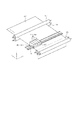
図1は、本発明で適用可能なカラーインクジェット記録装置の一実施形態の構成を示す概要斜視図である。インクタンク205〜208は、4色のインク(黒、シアン、マゼンタ、黄:K、C、M、Y)をそれぞれ収容しており、これら4色のインクを記録ヘッド201〜204に対して供給可能に構成されている。記録ヘッド201〜204は、4色のインクに対応して設けられ、インクタンク205〜208から供給されるインクを吐出できるように構成されている。
FIG. 1 is a schematic perspective view showing the configuration of an embodiment of a color ink jet recording apparatus applicable in the present invention. The
搬送ローラ103は、補助ローラ104とともに記録媒体(記録用紙)107を挟持しながら回転して記録媒体107を搬送するとともに、記録媒体107を保持する役割も担っている。キャリッジ106は、インクタンク205〜208及び記録ヘッド201〜204を搭載可能であって、これら記録ヘッド及びインクタンクを搭載しながらX方向沿って往復移動可能に構成されている。このキャリッジ106の往復移動中に記録ヘッドからインクが吐出され、これにより記録媒体に画像が記録される。記録ヘッド201〜204の回復動作時等の非記録動作時には、このキャリッジ106は図中の点線で示したホームポジション位置hに待機するように制御される。
The conveyance roller 103 rotates together with the
図1に示すホームポジションhに待機している記録ヘッド201〜204は、記録開始命令が入力されると、キャリッジ106と共に図中X方向に移動しつつ、インクを吐出して記録媒体107上に画像を記録する。この記録ヘッドの1回の移動(走査)によって、記録ヘッド201の吐出口の配列範囲に対応した幅を有する領域に対して記録が行われる。キャリッジ106の主走査方向(X方向)への1回の走査に伴う記録が終了すると、キャリッジ106はホームポジションhに戻り、再び図中のX方向へ走査しながら記録ヘッド201〜204で記録を行う。前回の記録走査が終了してから続く記録走査が始まる前には、搬送ローラ103が回転して、主走査方向と交差する副走査方向(Y方向)へと記録媒体が搬送される。このように記録ヘッドの記録走査と記録媒体の搬送とを繰り返すことにより記録媒体107に対する画像の記録が完成する。記録ヘッド201〜204からインクを吐出する記録動作は、後述の制御手段による制御に基づいて行われる。
The recording heads 201 to 204 waiting at the home position h shown in FIG. 1 discharge ink onto the
なお、上記の例では、記録ヘッドが往路方向に走査する時にのみ記録動作を行う、いわゆる片方向記録を行う場合について説明した。しかし、記録ヘッドが往路方向への走査時と復路方向への走査時の両方において記録を行う、いわゆる双方向記録を行うものにも本発明は適用可能である。また、上記の例では、インクタンク205〜208と記録ヘッド201〜104とを分離可能にキャリッジ106に搭載する構成を示した。しかし、インクタンク205〜208と記録ヘッド201〜204とが一体となったカートリッジをキャリッジに搭載する形態を採用してもよい。さらに、一つの記録ヘッドから複数色のインクを吐出可能な複数色一体型のヘッドをキャリッジに搭載する形態を採用しても
よい。
In the above example, the case where so-called unidirectional recording is performed in which the recording operation is performed only when the recording head scans in the forward direction has been described. However, the present invention can also be applied to what performs so-called bidirectional recording in which the recording head performs recording both when scanning in the forward direction and when scanning in the backward direction. In the above example, the configuration in which the
図2は、図1に示したカラーインクジェット記録装置の記録制御系回路の概略構成を示すブロック図である。インクジェット記録装置600は、インターフェイス400を介して、ホストコンピュータ(以下、ホストPC)1200等のデータ供給装置に接続されている。データ供給装置から送信される各種データや記録に関連する制御信号等は、インクジェット記録装置600の記録制御部500に入力される。記録制御部500は、インターフェース400を介して入力された制御信号に従って後述のモータドライバ403〜404やヘッドドライバ405を制御する。また、記録制御部500は、入力される画像データの処理(例えば、図4や図5に示されるデータ処理)や後述のヘッド種別信号発生回路405より入力される信号の処理を行う。401は、記録媒体107の搬送のために搬送ローラ103を回転させるための搬送モータである。402は、記録ヘッド201〜204を搭載するキャリッジ106を往復移動させるためのキャリッジモータである。403、404は、搬送モータ401、キャリッジモータ402をそれぞれ駆動するためのモータドライバである。405は記録ヘッド201〜204を駆動するヘッドドライバであり、記録ヘッドの数に対応して複数設けられている。また、406はヘッド種別信号発生回路であり、キャリッジ106に搭載されている記録ヘッド201〜204の種類や数を示す信号を記録制御部500に供給する。
FIG. 2 is a block diagram showing a schematic configuration of a recording control system circuit of the color inkjet recording apparatus shown in FIG. The ink
(実施形態1)
実施形態1においては、文字、線画、無属性(文字及び線画以外)からなる属性情報を判別し、属性が文字あるいは線画と判別された画像に関してその非エッジ部を検出する。さらに、画像のサイズ情報として文字及び線画のポイント数情報を取得し、文字及び線画のポイント数情報に応じて非エッジ部を間引くための間引きマスクを選択する。具体的には、文字及び線画のポイント数が閾値(所定のポイント数)よりも小さい場合、つまり、画像のサイズが所定のサイズ未満の場合には、間引き率の高い間引きマスクを選択する。一方、文字及び線画のポイント数が閾値(所定のポイント数)よりも大きい場合、つまり、画像のサイズが所定のサイズ以上の場合には、間引き率の低い間引きマスクを選択する。このように画像(ここでは、文字や線画)のサイズに応じて非エッジ部の間引き率を変えることで、画像のサイズが増大したときに起こる画像濃度の低下に伴う画像劣化を抑制することができる。以下、このことについて、図3を参照して説明する。
(Embodiment 1)
In the first embodiment, attribute information including characters, line drawings, and no attributes (other than characters and line drawings) is determined, and a non-edge portion is detected with respect to an image whose attributes are determined to be characters or line drawings. Furthermore, the information on the number of points of characters and line drawings is acquired as the size information of the image, and a thinning mask for thinning out the non-edge portion is selected according to the number of points information of characters and line drawings. Specifically, when the number of points of characters and line drawings is smaller than a threshold value (predetermined number of points), that is, when the image size is less than the predetermined size, a thinning mask having a high thinning rate is selected. On the other hand, when the number of points of characters and line drawings is larger than a threshold value (predetermined number of points), that is, when the image size is equal to or larger than the predetermined size, a thinning mask with a low thinning rate is selected. In this way, by changing the thinning rate of the non-edge portion according to the size of the image (here, text or line drawing), it is possible to suppress image degradation due to a decrease in image density that occurs when the image size increases. it can. Hereinafter, this will be described with reference to FIG.
図3は、エッジ部で囲まれる画像の非エッジ部を間引くことで得られた間引き画像(以下、「非エッジ部間引き画像」という)の模式図及びその濃度分布を表す概念図である。図3(a)〜図3(c)は、非エッジ部間引き画像の模式図を示す。図3(d)〜図3(f)は、図3(a)〜図3(c)それぞれの濃度分布を表す概念図を示す。図3(a)は、小さい画像の非エッジ部をある間引き率で間引くことで得られた非エッジ部間引き画像の模式図である。図3(b)は、大きい画像の非エッジ部を図4(a)と同じ間引き率で間引くことで得られた非エッジ部間引き画像の模式図である。図3(c)は大きい画像の非エッジ部を図3(a)よりも低い間引き率で間引くことで得られた非エッジ部間引き画像の模式図である。図3(d)は図3(a)のA−A’間の濃度分布である。図3(e)は図3(b)のB−B’間の濃度分布である。図3(f)は図3(c)のC−C’間の濃度分布である。実線は、画像濃度(OD値)を示す。また、人間の視覚特性を考慮すると、濃度を視認するのは0〜8cycle/mmであり、例えば1200dpiのプリンタであれば、6画素程度以上の幅を持つエリアである。従って、人間の目は着目点の周囲の複数画素の濃度を見ていることになる。そこで、点線として、この周囲の複数画素の画像濃度の移動平均、即ち、マクロ的に画像を観察した場合の見かけ上の濃度(マクロ濃度)を示す。 FIG. 3 is a schematic diagram showing a thinned image obtained by thinning out non-edge portions of an image surrounded by edge portions (hereinafter referred to as “non-edge portion thinned image”) and a conceptual diagram showing density distribution thereof. Fig.3 (a)-FIG.3 (c) show the schematic diagram of a non-edge part thinning image. FIGS. 3D to 3F are conceptual diagrams showing the concentration distributions of FIGS. 3A to 3C. FIG. 3A is a schematic diagram of a non-edge portion thinned image obtained by thinning a non-edge portion of a small image at a thinning rate. FIG. 3B is a schematic diagram of a non-edge portion thinned image obtained by thinning a non-edge portion of a large image at the same thinning rate as in FIG. FIG. 3C is a schematic diagram of a non-edge portion thinned image obtained by thinning out a non-edge portion of a large image at a thinning rate lower than that in FIG. FIG. 3D shows a concentration distribution between A and A ′ in FIG. FIG. 3E shows a concentration distribution between B and B ′ in FIG. FIG. 3F shows a concentration distribution between C and C ′ in FIG. The solid line indicates the image density (OD value). In consideration of human visual characteristics, the density is visually recognized from 0 to 8 cycles / mm. For example, in a 1200 dpi printer, the area has a width of about 6 pixels or more. Therefore, the human eye sees the density of a plurality of pixels around the point of interest. Therefore, as a dotted line, the moving average of the image densities of the plurality of surrounding pixels, that is, the apparent density (macro density) when the image is observed macroscopically is shown.
図3(d)の中心部、すなわち、小さい画像の非エッジ部のマクロ濃度は、エッジ部のOD値の影響を受けて、非エッジ部のOD値よりも高くなる。図3(e)及び(f)の中心部、すなわち、大きい画像の非エッジ部のマクロ濃度は、エッジ部までの距離が長いために、エッジ部のOD値の影響を受けづらく、非エッジ部のOD値よりも高くなりにくい。このため、図3(d)の非エッジ部のOD値と図3(e)の非エッジ部のOD値とは等しいが、図3(d)の非エッジ部のマクロ濃度と図3(e)の非エッジ部のマクロ濃度とは異なることになる。非エッジ部の間引き率を図3(e)よりも低く設定することで図3(e)よりも高いOD値を実現している図3(f)では、非エッジ部のマクロ濃度が、図3(e)よりも高くなる。 The macro density of the central portion of FIG. 3D, that is, the non-edge portion of the small image is affected by the OD value of the edge portion and becomes higher than the OD value of the non-edge portion. The macro density of the central portion of FIGS. 3E and 3F, that is, the non-edge portion of a large image is not easily affected by the OD value of the edge portion because the distance to the edge portion is long. It is hard to be higher than the OD value. Therefore, the OD value of the non-edge portion of FIG. 3D is equal to the OD value of the non-edge portion of FIG. 3E, but the macro density of the non-edge portion of FIG. ) Is different from the macro density of the non-edge portion. In FIG. 3F in which the OD value higher than that in FIG. 3E is realized by setting the thinning rate of the non-edge portion lower than that in FIG. 3E, the macro density of the non-edge portion is It becomes higher than 3 (e).
換言すると、大きい画像において、図3(d)に示す小さい画像のマクロ濃度と同程度のマクロ濃度を得るためには、図3(e)に示すOD値ではなく、図3(f)に示すOD値が必要となる。即ち、図3(f)のように画像領域が大きい場合には、そのマクロ濃度が図3(d)と同程度になるように非エッジ部の間引き率を低く設定する必要がある。このように、大きなサイズの画像の非エッジ部の間引き率を、小さいサイズの画像の非エッジ部の間引き率よりも低く設定することにより、画像サイズが増大したときに起こる画像濃度(マクロ濃度)の低下を抑制することができる。従って、画像(実施形態1では、文字・線画)のサイズに応じて非エッジ部の間引き率を変えることで、画像のサイズに関わらず十分な濃度を有する高品位な画像を得ることができる。 In other words, in order to obtain a macro density similar to that of the small image shown in FIG. 3D in a large image, the OD value shown in FIG. 3E is used instead of the OD value shown in FIG. OD value is required. That is, when the image area is large as shown in FIG. 3F, it is necessary to set the thinning-out rate of the non-edge portion low so that the macro density becomes the same as that in FIG. In this way, the image density (macro density) that occurs when the image size increases by setting the thinning rate of the non-edge portion of the large size image lower than the thinning rate of the non-edge portion of the small size image. Can be suppressed. Therefore, a high-quality image having a sufficient density can be obtained regardless of the size of the image by changing the thinning rate of the non-edge portion according to the size of the image (character / line drawing in the first embodiment).
図4は、インクジェット記録装置とホストPCとで構成される画像処理システムにおける画像データ処理を行う概略構成を示す機能ブロック図である。インクジェット記録装置の記録制御部500は、図2のインターフェイス介して、プリンタドライバがインストールされたホストホストPC1200より転送されるデータの処理を行う。
FIG. 4 is a functional block diagram illustrating a schematic configuration for performing image data processing in an image processing system including an inkjet recording apparatus and a host PC. The
ホストPC1200では、アプリケーションから入力画像データ1000を受け取る。この入力画像データ1000は、画像構成要素の種類に関する情報(画像の属性情報)と、文字及び線画のポイント数に関する情報を含んでいる。まず、受け取った入力画像データ1000を1200dpiの解像度でレンダリング処理1001を行う。これによって、記録用多値RGBデータ1002が生成される。本実施形態では、記録用多値RGBデータ1002は256値のデータである。一方、入力画像データ1000に基づき、記録すべき画像内に含まれる複数種の画像構成要素である文字及び線画のオブジェクト判別処理1003を行う。オブジェクト判別処理1003で判別された文字データ1004及び線画データ1005について、それぞれ、プリンタドライバよりポイント数に関する情報を取得するポイント数検出処理1006、1007を行う。続いて文字データ1004及び線画データ1005それぞれに対してレンダリング処理1008、1009を行う。これにより、解像度1200dpiの2値の文字オブジェクトデータ1010及び2値の線画オブジェクトデータ1011が生成される。以上のように生成された記録用多値RGBデータ1002と2値の各オブジェクトデータ1011、1012は記録制御部500に転送される。また、ポイント数検出処理1006、1007それぞれによって得られた文字ポント数に関する情報1022および線画ポント数に関する情報1023についても記録制御部500に転送される。
The
記録制御部500では、記録用多値RGBデータ1002を多値(256値)KCMYデータ1013に変換するための色変換処理1012を行う。次いで、多値(256値)KCMYデータ1013を量子化処理1014(例えば、誤差拡散処理)によって量子化(2値化)する。これにより、解像度1200dpiの2値KCMYデータ1015が生成される。一方、記録制御部500に転送された2値の文字オブジェクトデータ1010及び2値の線画オブジェクトデータ1011に対しては、それぞれ、非エッジ部検出処理1016、1017を行う。これにより、2値の文字非エッジ部データ1018、2値の文字エッジ部データ1019、2値の線画非エッジ部データ1020、2値の線画エッジ部データ1021が生成される。
The
最後に、2値KCMYデータ1015と、2値の文字非エッジ部データ1018、2値の文字エッジ部データ1019、2値の線画非エッジ部データ1020、2値の線画エッジ部データ1021、文字ポイント数に関する情報1022および線画ポイント数に関する情報1023に基づいて、後述するオブジェクト別データ処理1024が行われる。 Finally, binary KCMY data 1015, binary character non-edge portion data 1018, binary character edge portion data 1019, binary line drawing non-edge portion data 1020, binary line drawing edge portion data 1021, character points Based on the information 1022 relating to the number and the information 1023 relating to the number of line drawing points, data processing 1024 for each object described later is performed.
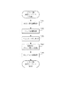
図5は、図4におけるオブジェクト別データ処理1024の手順を示すフローチャートである。なお、このオブジェクト別データ処理1024では、色別(KCMY)に同様の処理が行われる。そのため、以下ではKのオブジェクト別データ処理について説明し、他色の処理についてはその説明を省略する。 FIG. 5 is a flowchart showing the procedure of the object-specific data processing 1024 in FIG. In the object-specific data processing 1024, the same processing is performed for each color (KCMY). Therefore, the data processing for each object of K will be described below, and the description of the processing for other colors is omitted.
図4および図5に示されるように、2値の文字非エッジ部データ1018、2値の文字エッジ部データ1019、2値の線画非エッジ部データ1020、2値の線画エッジ部データ1021、Kの2値データ1015、文字ポイント数に関する情報1022および線画ポイント数に関する情報1023が入力されたことに応じて、Kのオブジェクト別データ処理シーケンスが開始する。 4 and 5, binary character non-edge portion data 1018, binary character edge portion data 1019, binary line drawing non-edge portion data 1020, binary line drawing edge portion data 1021, K In response to the input of binary data 1015, information 1022 regarding the number of character points, and information 1023 regarding the number of line drawing points, the data processing sequence for each object of K starts.
まず、着目画素の画像属性が文字あるいは線画のいずれかであるか否かを判定する(S101)。続いて、文字あるいは線画と判定された画像データに関して、非エッジ部か否かを判定する(S102)。さらに、非エッジ部と判定された画像に関して、文字か否かを判定する(S103)。文字と判定された画像に関して、文字ポイント数の情報を参照する(S104)。次いで、個々の文字に対してポイント数が10ポイント(閾値)未満であるか10ポイント以上であるかを判定する(S105)。ポイント数が10ポイント未満であると判定された場合、10ポイント未満の文字データを間引くためのマスクとして75%間引きマスクを選択する(S106)。このような間引きマスクの選択によって間引き率が決定される。続いて、この75%間引きマスクを用いて文字データを間引くことにより、着目画素のKの間引き文字データを生成する。このような処理を複数画素について行うことで生成されたデータの集合を、Kの間引き文字データ(I)とする(S107)。一方、ポイント数が10ポイント以上であると判定された場合、10ポイント以上の文字データを間引くためのマスクとして50%間引きマスクを選択する(S108)。続いて、この50%間引きマスクを用いて文字データを間引くことにより、着目画素のKの間引き文字データを生成する。このような処理を複数画素について行うことで生成されたデータの集合を、Kの間引き文字データ(II)とする(S109)。S107及びS109で生成されたKの間引き文字データ(I)とKの間引き文字データ(II)を合成し、Kの合成文字データを生成する(S110)。 First, it is determined whether the image attribute of the pixel of interest is either a character or a line drawing (S101). Subsequently, it is determined whether or not the image data determined to be a character or a line drawing is a non-edge portion (S102). Further, it is determined whether or not the image is determined to be a non-edge portion (S103). For the image determined to be a character, information on the number of character points is referred to (S104). Next, it is determined whether the number of points for each character is less than 10 points (threshold value) or more than 10 points (S105). When it is determined that the number of points is less than 10 points, a 75% thinning mask is selected as a mask for thinning out character data of less than 10 points (S106). The thinning rate is determined by such selection of the thinning mask. Subsequently, the thinned character data of the pixel of interest is generated by thinning the character data using the 75% thinning mask. A set of data generated by performing such processing for a plurality of pixels is set as K thinned character data (I) (S107). On the other hand, if it is determined that the number of points is 10 points or more, a 50% thinning mask is selected as a mask for thinning out character data of 10 points or more (S108). Subsequently, by thinning out character data using the 50% thinning mask, K thinned character data of the pixel of interest is generated. A set of data generated by performing such processing for a plurality of pixels is set as K thinned character data (II) (S109). The K thinned character data (I) and the K thinned character data (II) generated in S107 and S109 are combined to generate K combined character data (S110).
次に、S105で線画と判定された画像に関して、線画ポイント数の情報を参照する(S111)。個々の線画に対してポイント数が4ポイント(閾値)未満であるか4ポイント以上であるかを判定する(S112)。ポイント数が4ポイント未満である判定された場合、この4ポイント未満の線画データを間引くためのマスクとして75%間引きマスクを選択する(S113)。続いて、この75%間引きマスクを用いて線画データを間引くことにより、着目画素のKの間引き線画データを生成する。このような処理を複数画素について行うことで生成されたデータの集合を、Kの間引き線画データ(I)とする(S114)。一方、ポイント数が4ポイント以上であると判定された場合、4ポイント以上の線画データを間引くためのマスクとして50%間引きマスクを選択する(S115)。続いて、この50%間引きマスクを用いて線画データを間引くことにより、着目画素のKの間引き線画データを生成する。このような処理を複数画素について行うことで生成されたデータの集合を、Kの間引き線画データ(II)とする(S116)。S114及びS116で生成されたKの間引き線画データ(I)とKの間引き線画データ(II)を合成し、Kの合成線画データを生成する(S117)。 Next, with respect to the image determined to be a line drawing in S105, information on the number of line drawing points is referred to (S111). It is determined whether the number of points for each line drawing is less than 4 points (threshold value) or more than 4 points (S112). When it is determined that the number of points is less than 4 points, a 75% thinning mask is selected as a mask for thinning line drawing data less than 4 points (S113). Subsequently, the thinned line drawing data of the pixel of interest is generated by thinning the line drawing data using the 75% thinning mask. A set of data generated by performing such processing for a plurality of pixels is set as K thinning line drawing data (I) (S114). On the other hand, when it is determined that the number of points is 4 points or more, a 50% thinning mask is selected as a mask for thinning line drawing data of 4 points or more (S115). Subsequently, K thinning line drawing data of the pixel of interest is generated by thinning line drawing data using the 50% thinning mask. A set of data generated by performing such processing for a plurality of pixels is set as K thinning line drawing data (II) (S116). The K thinning line drawing data (I) and the K thinning line drawing data (II) generated in S114 and S116 are combined to generate K combined line drawing data (S117).
さらに、S101で画像属性が文字あるいは線画以外(つまり、無属性)と判定された画素の集合をKの無属性データとし、S102でエッジ部と判断された画素の集合をKの文字/線画のエッジ部データとする(S118)。 Further, a set of pixels whose image attribute is determined to be other than character or line drawing (that is, no attribute) in S101 is defined as K no-attribute data, and a set of pixels determined as an edge portion in S102 is set to K character / line drawing. Edge data is set (S118).
S110、S117、S118で生成されたKの文字/線画エッジ部データ、Kの無属性データ、Kの合成文字データ、Kの合成線画データを合成し、Kの合成データ(Kの記録データ)を生成する(S119)。 The K character / line drawing edge portion data, the K attribute-free data, the K composite character data, and the K composite line drawing data generated in S110, S117, and S118 are combined, and the K composite data (K recording data) is combined. Generate (S119).
上記のKのオブジェクト別データ処理をCMYについても同様に行う。この後、ヘッドドライバ405を通して記録ヘッド201〜204へ各色記録データを転送し、各々の記録ヘッドで記録を行う。
The above K-by-object data processing is similarly performed for CMY. Thereafter, each color recording data is transferred to the recording heads 201 to 204 through the
図6(a)は、図4に示される非エッジ部の検出処理(1016、1017)を示すフローチャートである。図6(b)および(c)は、この検出処理で用いられるマトリックスと着目画素の関係を示す模式図である。まず、画像データの着目画素に記録すべきドットを示すデータが存在し、かつ、着目画素を中心とする3×3のマトリックス内の記録ドット数が9であるか否かを判定する(S201)。総記録ドット数が9の場合は着目画素のビットをONにする(S202)。総記録ドット数が9でない場合には、着目画素のビットをOFFにする(S203)。続いて、画像データの着目画素を走査方向に1画素分シフトさせる(S204)。この動作を繰り返し行い、全ての画像データの画素について検出処理が終了したか否かの判断を行い(S205)、終了した場合には、画像データの非エッジ部の検出処理を終了(S206)とし、終了していなければS201へ戻り上記処理を繰り返す。 FIG. 6A is a flowchart showing the non-edge portion detection processing (1016, 1017) shown in FIG. FIGS. 6B and 6C are schematic diagrams showing the relationship between the matrix used in this detection process and the pixel of interest. First, it is determined whether or not there is data indicating a dot to be recorded in the target pixel of the image data and the number of recording dots in the 3 × 3 matrix centering on the target pixel is nine (S201). . If the total number of recorded dots is 9, the bit of the target pixel is turned ON (S202). If the total number of recorded dots is not 9, the bit of the target pixel is turned OFF (S203). Subsequently, the pixel of interest of the image data is shifted by one pixel in the scanning direction (S204). This operation is repeated to determine whether or not the detection process has been completed for all the pixels of the image data (S205). If the process has been completed, the detection process of the non-edge portion of the image data is terminated (S206). If not completed, the process returns to S201 and the above process is repeated.
なお、ここでは、図6(b)に示されるマトリックスを用いる場合について説明したが、検出処理に用いられるマトリクスの構造はこれに限られるものではない。例えば、図6(c)のような着目画素とそれに隣接する4つ画素とからなるマトリクスを用い、そのマトリックス内の記録ドット数が5か否かを判定し、5と判定された場合にその着目画素を非エッジ部として検出してもよい。 Although the case where the matrix shown in FIG. 6B is used has been described here, the structure of the matrix used for the detection process is not limited to this. For example, using a matrix composed of a pixel of interest as shown in FIG. 6C and four pixels adjacent thereto, it is determined whether the number of recording dots in the matrix is 5, and if it is determined that the number is 5, The pixel of interest may be detected as a non-edge portion.
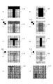
次に、上記図4〜図6で説明した非エッジ検出処理、間引き処理、記録データ生成処理について、図7〜図9を参照して説明する。なお、図7〜図9では、Kを例に説明するがCMYについても同様の処理を行う。図7は上記非エッジ部の検出処理を模式的に示した図である。図7(a)は、Kの2値データ1015である。このKの2値データ1015は12ポイントの文字2001、7ポイントの文字2002、5ポイントの線画2003、2ポイントの線画2004、無属性画像2005によって構成されている。図7(b)は、2値の文字オブジェクトデータ3200、3203である。図7(c)は、2値の文字非エッジ部データ3000、3003である。図7(d)は、2値の文字エッジ部データ3100、3103である。図7(e)は、2値の線画オブジェクトデータ3207、3210である。図7(f)は、2値の線画非エッジ部データ3007、3010である。図7(g)は、2値の線画エッジ部データ3107、3110である。図7(b)のデータから図7(c)及び(d)のデータを生成する方法は次の通りである。すなわち、図6で説明した通り、図7(b)に表す2値の文字オブジェクトデータ3200、3203について着目画素を順次1画素ずつシフトさせながら非エッジ部の検出処理を行う。着目画素を含む3×3マトリックス内の総記録ドット数が9の場合にその着目画素のビットをONにしていく。こうしてビットがONされた画素の集合体が、図7(c)に表す2値の文字非エッジ部データ3000、3003となる。さらに、上記のようにして生成した文字非エッジ部データ3000、3003と2値の文字オブジェクトデータ3200、3203の排他的理論和(EX−OR)をとることで、図7(d)に表す2値の文字エッジ部データ3100、3103を生成する。同様に、図7(e)に示す2値の線画オブジェクトデータから、図7(f)に示す2値の線画非エッジ部データ3007、3010及び図7(g)に示す2値の線画エッジ部データ3107、3110を生成する。
Next, the non-edge detection process, the thinning process, and the recording data generation process described with reference to FIGS. 4 to 6 will be described with reference to FIGS. 7 to 9, K is described as an example, but the same processing is performed for CMY. FIG. 7 is a diagram schematically showing the non-edge portion detection process. FIG. 7A shows binary data 1015 for K. The K binary data 1015 is composed of a 12-
なお、文字及び線画以外の無属性画像2005については処理を行わない。ここでは、エッジ部を輪郭の1画素とし、非エッジ部を輪郭の1画素を除く画素として検出したが、これに限定されるものでなくエッジ部を複数の画素として検出してもよい。エッジ部を複数の画素として検出するには、先に生成した非エッジ部データに対して非エッジ部検出処理を繰り返し行うことで可能となる。また、ここでは非エッジ部を検出したが、エッジ部を検出することでエッジ部データと非エッジ部データを生成してもよい。
Note that no-
図8は、文字及び線画の非エッジ部データの間引き処理、合成文字データ及び合成線画データの生成処理を模式的に表す図である。図8(a)は、図7(c)に示す2値の文字非エッジ部データ3000であり、10ポイント以上の文字である。このため、2値の文字非エッジ部データ3000と間引き率50%の間引きマスク3001との理論積を行うことで、図8(b)に示す間引き文字データ(I)3002を生成する。図8(c)は、図7(c)に示す2値の非エッジ部データ3003であり、10ポイント未満の文字である。このため、2値の文字非エッジ部データ3003と間引き率75%の間引きマスク3004との理論積を行うことにより、図8(d)に示す間引き文字データ(II)3005を生成する。さらに、間引き文字データ(I)3002と間引き文字データ(II)3005との理論和をとることで、図8(e)に示すKの合成文字データ3006を生成する。
FIG. 8 is a diagram schematically illustrating a thinning process of non-edge portion data of characters and line drawings and a generation process of combined character data and combined line drawing data. FIG. 8A shows the binary character
図8(f)は、図7(e)に示す2値の線画非エッジ部データ3007であり、4ポイント以上の線画である。このため、2値の線画非エッジ部データ3007と間引き率50%の間引きマスク3008との理論積を行うことにより、図8(g)に示す間引き線画データ(I)3009を生成する。図8(h)は、図7(e)に示す2値の非エッジ部データ3010であり、4ポイント未満の線画である。このため、2値の線画非エッジ部データ3010と間引き率50%の間引きマスク3011との理論積を行うことにより、図8(i)に示す間引き線画データ(I)3012を生成する。さらに、Kの間引き線画データ(I)3009とKの間引き線画データ(II)3012との理論和をとることで、図8(j)に示すKの合成線画データ3013を生成する。
FIG. 8F shows the binary line drawing
図9は、記録データ生成処理を模式的に表す図である。図9(a)は、図7(d)及び(g)に示される文字/線画のエッジ部データ及び図7(a)の無属性画像2005である。この図9(a)のデータと、図9(b)に示す合成文字データ3006(図8(e)と同じ)及び図9(c)に示す合成線画データ3013(図9(j)と同じ)との理論和をとることで、図9(d)のようなKの記録データを生成する。この図9(d)の記録データが図6のS119で生成されるKの記録データとなる。これにより、比較的サイズの大きな文字・線画については、比較的サイズの小さな文字・線画よりも、非エッジ部の間引き率を低く設定できる。従って、図3で説明したような、画像のサイズによらず同じ間引き率を設定した場合に生じる画像濃度低下に伴う画像劣化を招かずに済む。
FIG. 9 is a diagram schematically illustrating the recording data generation process. FIG. 9A shows the character / line drawing edge data shown in FIGS. 7D and 7G and the
なお、本実施形態では、画像サイズに応じた間引き率の設定処理を、文字と線画の両種の画像に対して行っているが、上記設定処理を文字のみあるいは線画のみに対して行うようにしてもよい。 In this embodiment, the thinning rate setting process according to the image size is performed on both types of images, that is, characters and line drawings. However, the above setting process is performed only on characters or line drawings. May be.
以上説明したように本実施形態によれば、非エッジ部の間引き率を、画像(文字あるいは線画)の大きさに応じて可変に設定している。これにより、画像(本例では、文字あるいは線画)のサイズに関わらず、エッジ部が鮮明で且つ非エッジ部の濃度が十分な高品位な画像を形成することが可能となる。また、非エッジ部の形成に使用される記録材の量も低減されるため、コスト低減効果も合わせて得ることできる。 As described above, according to the present embodiment, the thinning rate of the non-edge portion is variably set according to the size of the image (character or line drawing). As a result, regardless of the size of the image (in this example, a character or a line drawing), it is possible to form a high-quality image with clear edge portions and sufficient non-edge portion density. Further, since the amount of the recording material used for forming the non-edge portion is also reduced, a cost reduction effect can be obtained.
(実施形態2)
上記実施形態1では、無属性データ、文字及び線画のエッジ部データに対しては間引きを行っていないが、この実施形態2では無属性データに対して間引き処理を行う。その他の点については実施形態1と同様である。
(Embodiment 2)
In the first embodiment, thinning processing is not performed on attributeless data, edge data of characters and line drawings, but in the second embodiment, thinning processing is performed on attributeless data. Other points are the same as in the first embodiment.
本実施形態では、図4におけるオブジェクト判別処理1003で文字及び線画以外に無属性の判別を行い、図5に示すS101で無属性と判定された着目画素の集合である無属性データに対して50%の間引きマスクを用いて間引き処理を行う。その後、間引き処理を施した無属性データと、間引き文字データ、間引き線画データ、文字/線画エッジ部データとを合成し、図9(e)に示すような文字及び線画の非エッジ部に加え無属性データも間引いた記録データを生成する。 In the present embodiment, non-attribute determination is performed in addition to characters and line drawings in the object determination processing 1003 in FIG. % Thinning is performed using a thinning mask. Thereafter, the attributeless data subjected to the thinning process, the thinned character data, the thinned line drawing data, and the character / line drawing edge portion data are synthesized and added to the non-edge portion of the character and line drawing as shown in FIG. Record data with attribute data thinned out is generated.
ここでは無属性データの間引き率を非エッジ部データの間引き率と同じ50%としたが、これに限定されるものではなく、無属性データと非エッジ部データとで間引き率を異ならせてもよい。要するに、無属性データの記録ドット数を低減できれば良い。 Here, the thinning rate of the attribute-free data is set to 50%, which is the same as the thinning rate of the non-edge portion data. However, the present invention is not limited to this. Good. In short, it suffices if the number of recorded dots of attributeless data can be reduced.
このように実施形態2によれば、文字及び線画の非エッジ部データに加え、無属性データについても間引き処理を行うので、実施形態1よりも低ランニングコスト化を図ることができる。 As described above, according to the second embodiment, the thinning process is also performed on the non-attribute data in addition to the non-edge portion data of the characters and line drawings. Therefore, the running cost can be reduced as compared with the first embodiment.
(実施形態3)
実施形態3では、ホストPC1200にて拡大/縮小の倍率が指定された場合に、指定された倍率に応じて文字および線画のポイント数を演算し、この演算により得られたポイント数情報に従って間引き率を決定する。その他の点については実施形態1と同様であるため、以下では実施形態1との相違点についてのみ説明する。
(Embodiment 3)
In the third embodiment, when the enlargement / reduction ratio is designated by the
図10は、実施形態3におけるポイント数演算処理を示すフローチャートである。このフローチャートに示される処理は、図4の文字ポイント数情報1022および線画ポイント数情報1023を取得する際に、ホストPC1200のプリンタドライバにおいて実行される。まず、実施形態1と同様に、図4の文字ポイント数検出処理1006および線画ポイント数検出処理1007において検出されたポイント数に関する情報を取得する(S401)。次いで、ホストPC1200において指定された拡大縮小倍率に関する情報を取得する(S402)。次いで、S401にて取得したポイント数に関する情報とS402にて取得した拡大縮小倍率に関する情報に基づいて、下記演算式(1)による演算処理を行い、印字ポイント数を算出する(S403)。S403にて算出された印字ポイント数の情報を、文字ポイント数情報1022および線画ポイント数情報1023として取得する(S404)。これにより、拡大縮小倍率に応じたポイント数の情報(1022、1023)を得ることができる。
ポイント数×((拡大/縮小倍率)^(0.5))=印字ポイント数 式(1)
このようにして得られたポイント数情報(1022、1023)はインクジェット記録装置の記録制御部500へ転送される。転送されたポイント数情報(1022、1023)は、オブジェクト別データ処理(図5参照)において間引き率を決定するのに利用される。すなわち、図5のオブジェクト別データ処理では、S104およびS111において図10のS404で得られた印字ポイント数の情報が参照され、この印字ポイント数に従って間引きマスクの選択(間引き率の決定)が行われる。よって、本実施形態によれば、拡大縮小倍率に依存するポイント数に適した間引き率の設定が可能となる。
FIG. 10 is a flowchart illustrating the point number calculation process according to the third embodiment. The processing shown in this flowchart is executed in the printer driver of the
Number of points x ((enlargement / reduction ratio) ^ (0.5)) = number of print points Formula (1)
The point number information (1022, 1023) thus obtained is transferred to the
(実施形態4)
実施形態4では、実施形態1で説明した文字のポイント数情報に加えてフォント情報を利用して文字のポイント数を演算する。すなわち、文字のポイント数情報と共にフォント情報を取得し、これら情報に従って文字のポイント数を演算し、この演算により得られた文字ポイント数情報に従って文字の非エッジ部の間引き率を決定する。その他の点については実施形態1と同様であるため、以下では実施形態1との相違点についてのみ説明する。
(Embodiment 4)
In the fourth embodiment, the number of character points is calculated using font information in addition to the character point number information described in the first embodiment. That is, the font information is acquired together with the character point number information, the character point number is calculated according to the information, and the non-edge portion thinning rate is determined according to the character point number information obtained by the calculation. Since the other points are the same as in the first embodiment, only differences from the first embodiment will be described below.
図12は、実施形態4におけるポイント数演算処理を示すフローチャートである。このフローチャートに示される処理は、図4の文字ポイント数情報1022を取得する際に、ホストPC1200のプリンタドライバにおいて実行される。まず、実施形態1と同様に、図4の文字ポイント数検出処理1006において検出された文字のポイント数に関する情報を取得する(S501)。次いで、入力画像データに含まれる文字のフォント情報あるいはホストPC1200において指定された文字のフォント情報を取得する(S502)。次いで、図11に示されるフォント変数テーブルを参照して、処理対象文字のフォントに対応した変数を取得する(S503)。なお、この図11のフォント変数テーブルはフォントと変数との対応関係を定めたテーブルであって、ポイント数に変数を乗算して得られる文字の太さがフォントによらず同等となるようにフォント別に変数が定められている。例えば、フォントが「ゴシック体」の場合には変数が「2、5」、フォントが「Century」の場合には変数が「1.6」というように、フォント別に変数が定められている。
FIG. 12 is a flowchart illustrating the point number calculation process according to the fourth embodiment. The processing shown in this flowchart is executed in the printer driver of the
次いで、S501にて取得したポイント数に関する情報とS503にて取得した変数に関する情報に基づいて、下記演算式(2)による演算処理を行い、印字ポイント数を算出する(S504)。S504にて算出された印字ポイント数の情報を、文字ポイント数情報1022として取得する(S505)。これにより、文字のフォントに応じたポイント数の情報1022を得ることができる。
ポイント数×変数=印字ポイント数 式(2)
このようにして得られた文字ポイント数情報1022はインクジェット記録装置の記録制御部500へ転送される。転送された文字ポイント数情報1022は、オブジェクト別データ処理(図5参照)において間引き率を決定するのに利用される。すなわち、図5のオブジェクト別データ処理では、S104において図12のS505で得られた印字ポイント数の情報が参照され、この印字ポイント数に従って間引きマスクの選択(間引き率の決定)が行われる。よって、本実施形態によれば、フォントにより文字の太さが増減してしまう場合であっても、フォントによらず文字の大きさを同等にしつつ適切な間引き率の設定が可能となる。
Next, based on the information regarding the number of points acquired in S501 and the information regarding the variables acquired in S503, the arithmetic processing according to the following arithmetic expression (2) is performed to calculate the number of print points (S504). Information on the number of print points calculated in S504 is acquired as character point number information 1022 (S505). Thereby, the information 1022 of the number of points according to the character font can be obtained.
Number of points x Variable = Number of print points Formula (2)
The character point number information 1022 thus obtained is transferred to the
(実施形態5)
上記実施形態1〜4では、文字あるいは線画のポイント数の情報に従って間引き率を決定しているのに対して、この実施形態5では、2値の画像データから得られる画像のサイズ情報に従って間引き率を決定する。その他の点については実施形態1と同様であるため、以下では実施形態1との相違点についてのみ説明する。
(Embodiment 5)
In the first to fourth embodiments, the thinning rate is determined according to the information on the number of points of characters or line drawings, whereas in this fifth embodiment, the thinning rate is determined according to image size information obtained from binary image data. To decide. Since the other points are the same as in the first embodiment, only differences from the first embodiment will be described below.
この実施形態5の画像処理システムでは、文字や線画のポイント数の情報は使用されない。そのため、図4のポイント数検出処理(1006,1007)は行われず、また、ポイント数情報(1022、1023)も生成されない。実施形態5の画像処理システムでは、図4の文字ポイント数検出処理1006の代わりに、後述する2値の文字オブジェクトデータ1010に基づく文字サイズ検出処理(A)が行われる。また、文字ポイント数情報1022の代わりに、文字サイズ情報1022Aが生成される。同様に、図4の線画ポイント数検出処理1007の代わりに、2値の線画オブジェクトデータ1010に基づく線画サイズ検出処理(A)が行われ、また、線画ポイント数情報1023の代わりに線画サイズ情報1023Aが生成される。 In the image processing system of the fifth embodiment, information on the number of points of characters and line drawings is not used. Therefore, the point number detection processing (1006, 1007) in FIG. 4 is not performed, and the point number information (1022, 1023) is not generated. In the image processing system of the fifth embodiment, a character size detection process (A) based on binary character object data 1010 described later is performed instead of the character point number detection process 1006 in FIG. Further, instead of the character point number information 1022, character size information 1022A is generated. Similarly, a line drawing size detection process (A) based on the binary line drawing object data 1010 is performed instead of the line drawing point number detection process 1007 in FIG. 4, and line drawing size information 1023A is used instead of the line drawing point number information 1023. Is generated.
ここで、文字サイズ検出処理(A)について説明する。この処理は、エッジ部で囲まれる文字毎に行われる。まず、エッジ部で囲まれる2値の文字オブジェクトデータ1010に関して、主走査方向(ラスタ方向)の画素幅をラスタ毎に検出し、副走査方向(カラム方向)の画素幅をカラム毎に検出する。つまり、ラスタ方向に連続して記録されるドットの数(連続ドット数)をラスタ毎に検出し、また、カラム方向に連続して記録されるドットの数をカラム毎に検出する。次に、こうして検出された複数の連続ドット数から最頻値を求め、この最頻値の情報を上記文字サイズ情報1022Aとする。この文字サイズ情報1022Aは記録制御部500へ転送され、オブジェクト別データ処理(図5参照)にて利用される。
Here, the character size detection process (A) will be described. This process is performed for each character surrounded by the edge portion. First, regarding the binary character object data 1010 surrounded by the edge portion, the pixel width in the main scanning direction (raster direction) is detected for each raster, and the pixel width in the sub-scanning direction (column direction) is detected for each column. That is, the number of dots recorded continuously in the raster direction (number of consecutive dots) is detected for each raster, and the number of dots recorded continuously in the column direction is detected for each column. Next, the mode value is obtained from the number of consecutive dots detected in this way, and this mode value information is used as the character size information 1022A. The character size information 1022A is transferred to the
図5のS104では、文字ポイント数を参照する代わりに上記文字サイズ情報1022Aを参照する。そして、S105において、文字サイズ情報1022Aとしての最頻値が所定値(例えば、14)以上である場合はS108へ進み、間引き率の低い間引きマスク(50%間引きマスク)を選択する(S108)。一方、S105において、最頻値が所定値未満である場合はS106へ進み、間引き率の高い間引きマスク(75%間引きマスク)を選択する(S106)。こうすることで、文字ポイント数情報を用いずに、文字のサイズに応じた間引き率を設定することができる。 In S104 of FIG. 5, the character size information 1022A is referred to instead of referring to the number of character points. In S105, if the mode value as the character size information 1022A is a predetermined value (for example, 14) or more, the process proceeds to S108, and a thinning mask (50% thinning mask) with a low thinning rate is selected (S108). On the other hand, if the mode value is less than the predetermined value in S105, the process proceeds to S106, and a thinning mask with a high thinning rate (75% thinning mask) is selected (S106). By doing so, it is possible to set the thinning rate according to the character size without using the character point number information.
線画サイズ検出処理(A)は、その処理対象が文字ではなく線画であること(2値の線画オブジェクトデータ1011から線画サイズ情報1023Aを生成すること)を除いて、文字サイズ検出処理(A)と同様であるため、その説明を省略する。なお、マスクを選択するための閾値は文字と線画で異ならせることが好ましい。 The line drawing size detection process (A) is the same as the character size detection process (A) except that the processing target is not a character but a line drawing (generation of line drawing size information 1023A from binary line drawing object data 1011). Since it is the same, the description is abbreviate | omitted. Note that the threshold for selecting a mask is preferably different for characters and line drawings.
ここでは、エッジ部で囲まれる2値の文字・線画オブジェクトデータ(1010、1011)について連続ドット数を検出したが、2値の文字・線画非エッジ部データ(1018、1020)から連続ドット数を検出してもよい。この場合、文字サイズ情報1022Aや線画サイズ情報1023Aは、記録制御部500において、2値の文字非エッジ部データ1018や2値の線画非エッジ部データ1020から生成されることになる。
Here, the number of continuous dots is detected for binary character / line drawing object data (1010, 1011) surrounded by the edge portion, but the number of continuous dots is detected from the binary character / line drawing non-edge portion data (1018, 1020). It may be detected. In this case, the character size information 1022A and the line drawing size information 1023A are generated from the binary character non-edge portion data 1018 and the binary line drawing non-edge portion data 1020 in the
また、上記では、連続ドット数の検出方向は、主走査方向(ラスタ方向)のみあるいは副走査方向(カラム方向)のみとしてよい。さらには、間引きマスクの選択(間引き率の決定)を行うためのサイズ情報として、連続ドット数の最頻値を用いる代わりに、連続ドット数の平均値もしくは最大値を用いてもよい。また、エッジ部で囲まれる画像(文字あるいは線画)毎に上記最頻値、平均値もしくは最大値を検出するのではなく、複数の文字で構成される文字列からなる画像ブロック毎に上記最頻値、平均値もしくは最大値を検出する構成であってもよい。 In the above description, the detection direction of the number of consecutive dots may be only the main scanning direction (raster direction) or only the sub-scanning direction (column direction). Further, instead of using the mode value of the continuous dot number, the average value or the maximum value of the continuous dot number may be used as the size information for selecting the thinning mask (deciding the thinning rate). In addition, instead of detecting the mode value, average value, or maximum value for each image (character or line drawing) surrounded by the edge portion, the mode is set for each image block composed of a character string composed of a plurality of characters. It may be configured to detect a value, an average value, or a maximum value.
(実施形態6)
上記実施形態5では、2値の画像データから検出した連続ドット数の最頻値、平均値もしくは最大値を画像のサイズ情報として利用している。これに対して、この実施形態6では、エッジ部で囲まれる2値の画像データの総ドット数を画像のサイズ情報として利用する。つまり、実施形態6では、実施形態5における文字サイズ検出処理(A)の代わりに、文字を構成する総ドット数を検出するための文字サイズ検出処理(B)を行う。そして、文字サイズ検出処理(B)によって検出された総ドット数の情報を文字サイズ情報Bとし、この文字サイズ情報Bに従って間引きマスクの選択(間引き率の決定)を行う。また、線画についても同様で、実施形態5における線画サイズ検出処理(A)の代わりに、線画を構成する総ドット数を検出するための線画サイズ検出処理(B)を行う。そして、線画サイズ検出処理(B)によって検出された総ドット数の情報を線画サイズ情報Bとし、この線画サイズ情報Bに従って間引きマスクの選択(間引き率の決定)を行う。その他の点については実施形態5と同様であるため、以下では実施形態5との相違点についてのみ説明する。
(Embodiment 6)
In the fifth embodiment, the mode value, average value, or maximum value of the number of consecutive dots detected from binary image data is used as image size information. On the other hand, in the sixth embodiment, the total number of dots of binary image data surrounded by the edge portion is used as image size information. That is, in the sixth embodiment, instead of the character size detection process (A) in the fifth embodiment, a character size detection process (B) for detecting the total number of dots constituting the character is performed. Then, information on the total number of dots detected by the character size detection process (B) is set as character size information B, and a thinning mask is selected (decision of a thinning rate) according to the character size information B. The same applies to the line drawing. Instead of the line drawing size detection process (A) in the fifth embodiment, line drawing size detection processing (B) for detecting the total number of dots constituting the line drawing is performed. Information on the total number of dots detected by the line drawing size detection process (B) is used as line drawing size information B, and a thinning mask is selected (decision of a thinning rate) according to the line drawing size information B. Since the other points are the same as in the fifth embodiment, only differences from the fifth embodiment will be described below.
ここで、文字サイズ検出処理(B)について説明する。まず、エッジ部で囲まれる2値の文字オブジェクトデータ1010から、当該データを構成する総ドット数を検出する。そして、この総ドット数の情報を上記文字サイズ情報1022Bとする。この文字サイズ情報1022Bは記録制御部500へ転送され、オブジェクト別データ処理(図5参照)にて利用される。
Here, the character size detection process (B) will be described. First, the total number of dots constituting the data is detected from the binary character object data 1010 surrounded by the edge portion. The information on the total number of dots is referred to as the character size information 1022B. This character size information 1022B is transferred to the
図5のS104では、文字ポイント数を参照する代わりに上記文字サイズ情報1022Bを参照する。そして、S105において、文字サイズ情報1022Bとしての総ドット数が所定値(例えば、200)以上である場合はS108へ進み、間引き率の低い間引きマスク(50%間引きマスク)を選択する(S108)。一方、S105において、総ドット数が所定値未満である場合はS106へ進み、間引き率の高い間引きマスク(75%間引きマスク)を選択する(S106)。こうすることで、文字ポイント数情報を用いずに、文字のサイズに応じた間引き率を設定することができる。 In S104 of FIG. 5, the character size information 1022B is referred to instead of referring to the number of character points. In S105, if the total number of dots as the character size information 1022B is equal to or larger than a predetermined value (for example, 200), the process proceeds to S108, and a thinning mask with a low thinning rate (50% thinning mask) is selected (S108). On the other hand, if the total number of dots is less than the predetermined value in S105, the process proceeds to S106, and a thinning mask having a high thinning rate (75% thinning mask) is selected (S106). By doing so, it is possible to set the thinning rate according to the character size without using the character point number information.
線画サイズ検出処理(A)は、その処理対象が文字ではなく線画であること(2値の線画オブジェクトデータ1011から線画サイズ情報1023Bを生成すること)を除いて、文字サイズ検出処理(A)と同様であるため、その説明を省略する。なお、マスクを選択するための閾値は文字と線画で異ならせることが好ましい。 The line drawing size detection process (A) is the same as the character size detection process (A) except that the processing target is not a character but a line drawing (generation of line drawing size information 1023B from binary line drawing object data 1011). Since it is the same, the description is abbreviate | omitted. Note that the threshold for selecting a mask is preferably different for characters and line drawings.
ここでは、エッジ部で囲まれる2値の文字・線画オブジェクトデータ(1010、1011)から総ドット数を検出したが、2値の文字・線画非エッジ部データ(1018、1020)から総ドット数を検出してもよい。また、エッジ部で囲まれる画像(文字あるいは線画)毎に総ドット数を検出するのではなく、1つの文字毎あるいは複数の文字で構成される文字列毎に上記総ドット数を検出する構成であってもよい。 Here, the total number of dots is detected from binary character / line drawing object data (1010, 1011) surrounded by the edge portion, but the total number of dots is detected from binary character / line drawing non-edge portion data (1018, 1020). It may be detected. In addition, the total number of dots is not detected for each image (character or line drawing) surrounded by the edge portion, but the total number of dots is detected for each character string composed of one character or a plurality of characters. There may be.
(実施形態7)
実施形態1〜6では、入力画像データに含まれる属性情報を判別することによって、画像の属性を判別しているが、画像の属性判別の方法はこれに限られるものではない。公知の手段によって文字あるいは線画を判別してもよい。従って、本発明では、属性情報が含まれていない入力画像データを利用することも可能である。
(Embodiment 7)
In the first to sixth embodiments, the attribute of the image is determined by determining the attribute information included in the input image data. However, the method for determining the attribute of the image is not limited to this. Characters or line drawings may be determined by a known means. Therefore, in the present invention, input image data that does not include attribute information can be used.
(実施形態8)
実施形態1〜7では、画像サイズに応じた間引き率決定処理を行う対象となる画像の種類を文字あるいは線画に制限しているが、本発明はこれに限られるものではない。上記決定処理を行う対象画像の種類として、文字および線画以外の画像(例えば、イメージ)を含めてもよい。また、上記決定処理を行う対象画像の種類を、文字および線画以外の画像(例えば、イメージ)だけに制限してもよい。
(Embodiment 8)
In the first to seventh embodiments, the type of image to be subjected to the thinning rate determination process according to the image size is limited to characters or line drawings, but the present invention is not limited to this. Images (for example, images) other than characters and line drawings may be included as the types of target images for which the determination process is performed. In addition, the types of target images on which the determination process is performed may be limited to images (for example, images) other than characters and line drawings.
文字および線画以外の画像(例えば、イメージ)の間引き率を決定する場合、まず、エッジ部で囲まれる画像を抽出し、次いで、抽出した画像に関して上記実施形態5〜6で説明したようなパラメータ(最頻値、平均値、総ドット数等)を取得する。そして、このパラメータを画像のサイズ情報として利用することで、画像の非エッジ部の間引き率を決定するのが好ましい。勿論、この形態であっても、上記実施形態と同じように、画像のサイズが所定のサイズ以上の場合に決定される間引き率を、画像のサイズが所定のサイズ未満の場合に決定される間引き率より低くする。 When determining a thinning rate of an image (for example, an image) other than characters and line drawings, first, an image surrounded by an edge portion is extracted, and then the parameters ( Mode, average value, total number of dots, etc.). Then, it is preferable to determine the thinning rate of the non-edge portion of the image by using this parameter as the image size information. Of course, even in this embodiment, as in the above embodiment, the thinning rate determined when the image size is equal to or larger than the predetermined size is the thinning rate determined when the image size is smaller than the predetermined size. Lower than rate.
さらには、上記決定処理を行う対象画像の種類をユーザが選択できる機能を設けてもよい。このような機能を設けることによりユーザニーズに適した間引き処理を実現することができる。 Furthermore, a function may be provided that allows the user to select the type of target image on which the determination process is performed. By providing such a function, thinning processing suitable for user needs can be realized.
(その他の実施形態)
上述した実施形態1〜8では、画像記録装置としてインクジェット記録装置を用いているが、本発明で適用可能な画像記録装置はこれに限られるものではなく、例えば、記録材としてトナーを用いる電子写真方式のプリンタを用いることもできる。
(Other embodiments)
In
また、上述した実施形態1〜8では、画像の非エッジの形成に使用される記録材(例えば、インクやトナー)の量を低減する方法として、画像の非エッジ部を構成する2値の記録データの数を低減する(記録データを間引く)方法について例示したが、本発明はこれに限られるものではない。例えば、画像の非エッジ部を構成する多値データの値(濃度値)を低減する方法を採用してもよい。多値データの値は、記録材の使用量におおよそ対応する。従って、多値データの値を低減させるための低減率を設定しても、記録材の使用量を上記低減率に応じた量だけ低減することができる。 In the first to eighth embodiments described above, as a method of reducing the amount of recording material (for example, ink or toner) used for forming a non-edge of an image, binary recording that forms a non-edge portion of the image is performed. Although a method for reducing the number of data (thinning out recorded data) has been illustrated, the present invention is not limited to this. For example, a method of reducing the value (density value) of multi-value data constituting a non-edge portion of an image may be employed. The value of the multi-value data roughly corresponds to the amount of recording material used. Therefore, even if a reduction rate for reducing the value of the multi-value data is set, the usage amount of the recording material can be reduced by an amount corresponding to the reduction rate.
更に述べると、2値の記録データの数を低減させるための低減率(間引き率)や多値データの値を低減させるための低減率を設定することは、記録材の使用量を低減させるための低減率を設定することに相当する。従って、画像の非エッジ部の形成に使用される記録材の量を低減するための低減率を画像のサイズ情報に応じて決定し、この決定された低減率に従って画像の非エッジ部の形成に使用される記録材の量を低減させる低減処理を実行すれば、非エッジ部を形成するための記録材の使用量を画像サイズに応じて適正化することができる。 More specifically, setting a reduction rate (decimation rate) for reducing the number of binary recording data or a reduction rate for reducing the value of multi-value data reduces the amount of recording material used. This is equivalent to setting the reduction rate. Therefore, a reduction rate for reducing the amount of recording material used for forming the non-edge portion of the image is determined according to the image size information, and the non-edge portion of the image is formed according to the determined reduction rate. If the reduction process for reducing the amount of recording material used is executed, the amount of recording material used for forming the non-edge portion can be optimized according to the image size.
また、上述した実施形態1〜8では、一連の画像データの処理を、画像記録装置の一形態であるインクジェット記録装置とデータ供給装置の一形態であるホストPCとで分担する構成としたが、本発明はこの構成に限定されるものではない。例えば、画像記録装置において図5に示した処理の全てを実行するようにしてもよいし、反対に、データ供給装置において図5に示した処理の全てを実行するようにしてもよい。要は、画像記録装置とデータ供給装置とで構成される画像処理システムにおいて、上記画像データの処理を実行できればよい。 In the first to eighth embodiments described above, a series of image data processing is shared between an inkjet recording apparatus which is one form of the image recording apparatus and a host PC which is one form of the data supply apparatus. The present invention is not limited to this configuration. For example, all of the processing shown in FIG. 5 may be executed in the image recording apparatus, and conversely, all of the processing shown in FIG. 5 may be executed in the data supply apparatus. In short, it is only necessary that the image data processing can be executed in an image processing system including an image recording device and a data supply device.
また、上記の実施形態では、本発明の特徴的な画像処理(画像のサイズ情報に応じて画像の非エッジ部のデータの間引き率を決定する処理)が画像記録装置にて実行されるので、画像記録装置が本発明の画像処理装置に該当することになる。一方、本発明の特徴的な画像処理がデータ供給装置で実行される場合には、データ供給装置(ホストPC)が本発明の画像処理装置に該当することになる。 In the above embodiment, the image processing characteristic of the present invention (processing for determining the thinning rate of data at the non-edge portion of the image according to the image size information) is executed by the image recording apparatus. The image recording apparatus corresponds to the image processing apparatus of the present invention. On the other hand, when the image processing characteristic of the present invention is executed by the data supply apparatus, the data supply apparatus (host PC) corresponds to the image processing apparatus of the present invention.
また、本発明は、以下の処理を実行することによっても実現される。即ち、上述した実施形態の機能を実現するソフトウェア(プログラム)を、ネットワーク又は各種記憶媒体を介してシステム或いは装置に供給し、そのシステム或いは装置のコンピュータ(またはCPUやMPU等)がプログラムを読み出して実行する処理である。 The present invention can also be realized by executing the following processing. That is, software (program) that realizes the functions of the above-described embodiments is supplied to a system or apparatus via a network or various storage media, and a computer (or CPU, MPU, or the like) of the system or apparatus reads the program. It is a process to be executed.
3000 12ポイントの文字非エッジ部データ
3001 50%間引きマスク
3002 間引き文字データ(I)
3003 7ポイントの文字非エッジ部データ
3004 75%間引きマスク
3005 間引き文字データ(II)
3006 合成文字データ
3007 5ポイントの線画非エッジ部データ
3008 50%間引きマスク
3009 間引き線画データ(I)
3010 2ポイントの線画非エッジ部データ
3011 70%間引きマスク
3012 間引き線画データ(II)
3013 合成線画データ
3000 12-point character
3003 7-point character
3006
3010 2-point line drawing
3013 Composite line drawing data
Claims (15)
前記画像に含まれるオブジェクトのサイズに関する情報を取得する取得手段と、
前記取得手段により取得された前記オブジェクトのサイズに関する情報に応じて、前記オブジェクトのエッジ領域と内部領域のうち該内部領域を記録するための前記記録材の付与量を低減させるための処理を行う低減手段と、を備え、
前記オブジェクトのサイズが第1のサイズの場合に単位領域あたりの前記記録材の付与量を低減させる量は、前記オブジェクトのサイズが前記第1のサイズよりも小さい第2のサイズの場合に前記単位領域あたりの前記記録材の付与量を低減させる量よりも少ないことを特徴とする画像処理装置。 An image processing apparatus for recording an image on a recording medium by applying a recording material,
Obtaining means for obtaining information on the size of an object included in the image;
Low processing for reducing the amount of recording material applied to record the inner area of the edge area and the inner area of the object according to the information on the size of the object acquired by the acquiring means. includes a reduction hand stage, the,
When the object size is the first size, the amount by which the recording material applied amount per unit area is reduced is the unit when the object size is the second size smaller than the first size. An image processing apparatus characterized in that the amount is less than the amount by which the recording material is applied per area.
前記取得手段は、前記オブジェクトの属性が文字と判定された場合に前記文字のサイズに関する情報を取得するための手段を含み、
前記低減手段は、前記文字のサイズに関する情報に応じて前記文字の内部領域に対する前記記録材の付与量を低減することを特徴とする請求項1に記載の画像処理装置。 A determination means for determining an attribute of the object;
The acquisition means includes means for acquiring information on the size of the character when the attribute of the object is determined to be a character.
The image processing apparatus according to claim 1, wherein the reducing unit reduces the amount of the recording material applied to the inner area of the character according to information on the size of the character.
前記取得手段は、前記オブジェクトの属性が線画と判定された場合に前記線画のサイズに関する情報を取得するための手段を含み、
前記低減手段は、前記線画のサイズに関する情報に応じて前記線画の内部領域に対する前記記録材の付与量を低減することを特徴とする請求項1に記載の画像処理装置。 A determination means for determining an attribute of the object;
The acquisition means includes means for acquiring information regarding the size of the line drawing when the attribute of the object is determined to be a line drawing,
The image processing apparatus according to claim 1, wherein the reduction unit reduces the amount of the recording material applied to the internal area of the line drawing according to information about the size of the line drawing.
前記画像に含まれるオブジェクトのサイズに関する情報を取得する取得工程と、
前記取得工程において取得された前記オブジェクトのサイズに関する情報に応じて前記オブジェクトのエッジ領域と内部領域のうち該内部領域を記録するための前記記録材の付与量を低減させるための処理を行う低減工程と、を備え、
前記低減工程において、前記オブジェクトのサイズが第1のサイズの場合に単位領域あたりの前記記録材の付与量を決定させる量は、前記オブジェクトのサイズが前記第1のサイズよりも小さい第2のサイズの場合に前記単位領域あたりの前記記録材の付与量を決定させる量よりも少ないことを特徴とする画像処理方法。 An image processing method for recording an image on a recording medium by applying a recording material,
An acquisition step of acquiring information about the size of an object included in the image;
A reduction step of performing a process for reducing the amount of the recording material for recording the inner region of the object according to the information on the size of the object acquired in the acquisition step. And comprising
In the reduction step, when the size of the object is the first size, an amount for determining the amount of the recording material applied per unit area is a second size in which the size of the object is smaller than the first size. In this case, the image processing method is less than the amount for determining the amount of the recording material applied per unit area.
前記取得工程は、前記オブジェクトの属性が文字と判定された場合に前記文字のサイズに関する情報を取得するための工程を含み、The obtaining step includes a step for obtaining information on the size of the character when the attribute of the object is determined to be a character,
前記低減工程において、前記文字のサイズに関する情報に応じて前記文字の内部領域に対する前記記録材の付与量を低減することを特徴とする請求項8に記載の画像処理方法。The image processing method according to claim 8, wherein, in the reducing step, the amount of the recording material applied to the inner area of the character is reduced according to information on the size of the character.
前記取得工程は、前記オブジェクトの属性が線画と判定された場合に前記線画のサイズに関する情報を取得するための工程を含み、The obtaining step includes a step for obtaining information about the size of the line drawing when the attribute of the object is determined to be a line drawing,
前記低減工程において、前記線画のサイズに関する情報に応じて前記線画の内部領域に対する前記記録材の付与量を低減することを特徴とする請求項8に記載の画像処理方法。The image processing method according to claim 8, wherein, in the reduction step, an amount of the recording material applied to an internal area of the line drawing is reduced according to information on the size of the line drawing.
Priority Applications (2)
| Application Number | Priority Date | Filing Date | Title |
|---|---|---|---|
| JP2009236437A JP5328601B2 (en) | 2009-10-13 | 2009-10-13 | Image processing apparatus and image processing method |
| US12/895,348 US8717630B2 (en) | 2009-10-13 | 2010-09-30 | Image processing apparatus and image processing method a thinning ratio applied when an image object has a first size is smaller than a thinning ratio applied when an image object has a second size smaller than the first size |
Applications Claiming Priority (1)
| Application Number | Priority Date | Filing Date | Title |
|---|---|---|---|
| JP2009236437A JP5328601B2 (en) | 2009-10-13 | 2009-10-13 | Image processing apparatus and image processing method |
Publications (3)
| Publication Number | Publication Date |
|---|---|
| JP2011087000A JP2011087000A (en) | 2011-04-28 |
| JP2011087000A5 JP2011087000A5 (en) | 2012-12-13 |
| JP5328601B2 true JP5328601B2 (en) | 2013-10-30 |
Family
ID=43854628
Family Applications (1)
| Application Number | Title | Priority Date | Filing Date |
|---|---|---|---|
| JP2009236437A Expired - Fee Related JP5328601B2 (en) | 2009-10-13 | 2009-10-13 | Image processing apparatus and image processing method |
Country Status (2)
| Country | Link |
|---|---|
| US (1) | US8717630B2 (en) |
| JP (1) | JP5328601B2 (en) |
Families Citing this family (3)
| Publication number | Priority date | Publication date | Assignee | Title |
|---|---|---|---|---|
| JP2014117885A (en) * | 2012-12-17 | 2014-06-30 | Canon Inc | Printer, printer control method, image processing device, image processing method, and program |
| JP6566277B2 (en) * | 2015-07-30 | 2019-08-28 | 京セラドキュメントソリューションズ株式会社 | Image processing device |
| JP2022117830A (en) * | 2021-02-01 | 2022-08-12 | キヤノン株式会社 | Image processing device, image processing method, recording device and program |
Family Cites Families (4)
| Publication number | Priority date | Publication date | Assignee | Title |
|---|---|---|---|---|
| JPH11254753A (en) * | 1998-03-06 | 1999-09-21 | Ricoh Co Ltd | Printer |
| US6753976B1 (en) * | 1999-12-03 | 2004-06-22 | Xerox Corporation | Adaptive pixel management using object type identification |
| JP2004157904A (en) * | 2002-11-08 | 2004-06-03 | Minolta Co Ltd | Printer control program and printer |
| JP4931204B2 (en) | 2005-12-01 | 2012-05-16 | キヤノン株式会社 | Data generating apparatus and data generating method |
-
2009
- 2009-10-13 JP JP2009236437A patent/JP5328601B2/en not_active Expired - Fee Related
-
2010
- 2010-09-30 US US12/895,348 patent/US8717630B2/en not_active Expired - Fee Related
Also Published As
| Publication number | Publication date |
|---|---|
| JP2011087000A (en) | 2011-04-28 |
| US20110085208A1 (en) | 2011-04-14 |
| US8717630B2 (en) | 2014-05-06 |
Similar Documents
| Publication | Publication Date | Title |
|---|---|---|
| JP7214404B2 (en) | IMAGE PROCESSING APPARATUS, IMAGE PROCESSING METHOD, AND PROGRAM | |
| JP2015092661A (en) | Image processing apparatus and image processing method | |
| JP2009096188A (en) | Ink jet recording apparatus and ink jet recording method | |
| JP5139876B2 (en) | Image forming apparatus and image forming method | |
| US10963761B2 (en) | Recording apparatus, recording method, and recording controlling device for printing code information | |
| US8885222B2 (en) | Image processing apparatus performing error diffusion process | |
| JP2012066576A (en) | Inkjet recording apparatus and recording method | |
| JP2012223970A (en) | Data processing apparatus, data processing method and inkjet printing apparatus | |
| JP5328601B2 (en) | Image processing apparatus and image processing method | |
| JP2008093852A (en) | Printer, printer control program, recording medium storing the program, printer control method, image processor, image processing program, recording medium storing the program and image processing method | |
| JP7439661B2 (en) | Image processing method, image processing device, and recording system | |
| JP5665453B2 (en) | Image processing apparatus and image processing method | |
| JP5084159B2 (en) | Inkjet recording apparatus, inkjet recording method, and program | |
| US20120314234A1 (en) | Image processing apparatus, image printing apparatus and image processing method | |
| US10872279B2 (en) | Image processing apparatus, printing system, printing apparatus, method of detecting print image, and storage medium | |
| US20120194594A1 (en) | Inkjet printing apparatus and inkjet printing method | |
| JP2004306392A (en) | Printer, controller, printing method, control method and program | |
| JP2005153157A (en) | Printer, printing controller, printing method, and program | |
| JP2006212792A (en) | Printer, printing program, printing method, image processor, image processing program, image processing method, and recording medium with the program recorded | |
| US20230385584A1 (en) | Printing apparatus, method of controlling printing apparatus, and storage medium | |
| JP2011119878A (en) | Image processor, and image processing method | |
| EP4249259A1 (en) | Method for generating ejection position data, device for generating ejection position data, and program | |
| JP5341420B2 (en) | Image processing apparatus and image processing method | |
| JP5341467B2 (en) | Image processing apparatus and image processing method | |
| JP2002331650A (en) | Apparatus and method for ink jet recording |
Legal Events
| Date | Code | Title | Description |
|---|---|---|---|
| A521 | Request for written amendment filed |
Free format text: JAPANESE INTERMEDIATE CODE: A523 Effective date: 20121015 |
|
| A621 | Written request for application examination |
Free format text: JAPANESE INTERMEDIATE CODE: A621 Effective date: 20121015 |
|
| A521 | Request for written amendment filed |
Free format text: JAPANESE INTERMEDIATE CODE: A523 Effective date: 20121025 |
|
| A977 | Report on retrieval |
Free format text: JAPANESE INTERMEDIATE CODE: A971007 Effective date: 20130530 |
|
| TRDD | Decision of grant or rejection written | ||
| A01 | Written decision to grant a patent or to grant a registration (utility model) |
Free format text: JAPANESE INTERMEDIATE CODE: A01 Effective date: 20130625 |
|
| A61 | First payment of annual fees (during grant procedure) |
Free format text: JAPANESE INTERMEDIATE CODE: A61 Effective date: 20130723 |
|
| LAPS | Cancellation because of no payment of annual fees |