JP5292263B2 - Film forming method and light emitting element manufacturing method - Google Patents
Film forming method and light emitting element manufacturing method Download PDFInfo
- Publication number
- JP5292263B2 JP5292263B2 JP2009266210A JP2009266210A JP5292263B2 JP 5292263 B2 JP5292263 B2 JP 5292263B2 JP 2009266210 A JP2009266210 A JP 2009266210A JP 2009266210 A JP2009266210 A JP 2009266210A JP 5292263 B2 JP5292263 B2 JP 5292263B2
- Authority
- JP
- Japan
- Prior art keywords
- abbreviation
- film
- layer
- substrate
- elastic substrate
- Prior art date
- Legal status (The legal status is an assumption and is not a legal conclusion. Google has not performed a legal analysis and makes no representation as to the accuracy of the status listed.)
- Expired - Fee Related
Links
- 238000000034 method Methods 0.000 title claims abstract description 39
- 238000004519 manufacturing process Methods 0.000 title claims description 5
- 239000000758 substrate Substances 0.000 claims abstract description 98
- 229910052751 metal Inorganic materials 0.000 claims abstract description 59
- 239000002184 metal Substances 0.000 claims abstract description 59
- 239000011368 organic material Substances 0.000 claims abstract description 53
- 230000015572 biosynthetic process Effects 0.000 claims abstract description 4
- 230000008021 deposition Effects 0.000 claims 1
- 238000010438 heat treatment Methods 0.000 abstract description 8
- 239000010408 film Substances 0.000 description 143
- 239000010410 layer Substances 0.000 description 110
- 239000004065 semiconductor Substances 0.000 description 78
- 239000000463 material Substances 0.000 description 43
- 239000000126 substance Substances 0.000 description 39
- 229910052757 nitrogen Inorganic materials 0.000 description 28
- 238000002347 injection Methods 0.000 description 25
- 239000007924 injection Substances 0.000 description 25
- -1 polyethylene Polymers 0.000 description 25
- XLOMVQKBTHCTTD-UHFFFAOYSA-N Zinc monoxide Chemical compound [Zn]=O XLOMVQKBTHCTTD-UHFFFAOYSA-N 0.000 description 19
- 238000002425 crystallisation Methods 0.000 description 15
- 230000005525 hole transport Effects 0.000 description 14
- 239000012535 impurity Substances 0.000 description 14
- 230000008025 crystallization Effects 0.000 description 13
- 239000012044 organic layer Substances 0.000 description 12
- 230000035939 shock Effects 0.000 description 12
- 229910052799 carbon Inorganic materials 0.000 description 10
- 239000002131 composite material Substances 0.000 description 10
- 229910021420 polycrystalline silicon Inorganic materials 0.000 description 10
- PXHVJJICTQNCMI-UHFFFAOYSA-N Nickel Chemical compound [Ni] PXHVJJICTQNCMI-UHFFFAOYSA-N 0.000 description 9
- 229910021417 amorphous silicon Inorganic materials 0.000 description 9
- 150000001875 compounds Chemical class 0.000 description 9
- 238000004544 sputter deposition Methods 0.000 description 9
- 239000011787 zinc oxide Substances 0.000 description 9
- AZFHXIBNMPIGOD-UHFFFAOYSA-N 4-hydroxypent-3-en-2-one iridium Chemical compound [Ir].CC(O)=CC(C)=O.CC(O)=CC(C)=O.CC(O)=CC(C)=O AZFHXIBNMPIGOD-UHFFFAOYSA-N 0.000 description 8
- CUJRVFIICFDLGR-UHFFFAOYSA-N acetylacetonate Chemical compound CC(=O)[CH-]C(C)=O CUJRVFIICFDLGR-UHFFFAOYSA-N 0.000 description 8
- 239000000956 alloy Substances 0.000 description 8
- 239000002585 base Substances 0.000 description 8
- KDLHZDBZIXYQEI-UHFFFAOYSA-N Palladium Chemical compound [Pd] KDLHZDBZIXYQEI-UHFFFAOYSA-N 0.000 description 7
- 229910045601 alloy Inorganic materials 0.000 description 7
- 239000011888 foil Substances 0.000 description 7
- 239000007789 gas Substances 0.000 description 7
- 239000010931 gold Substances 0.000 description 7
- 229910003437 indium oxide Inorganic materials 0.000 description 7
- PJXISJQVUVHSOJ-UHFFFAOYSA-N indium(iii) oxide Chemical compound [O-2].[O-2].[O-2].[In+3].[In+3] PJXISJQVUVHSOJ-UHFFFAOYSA-N 0.000 description 7
- BASFCYQUMIYNBI-UHFFFAOYSA-N platinum Chemical compound [Pt] BASFCYQUMIYNBI-UHFFFAOYSA-N 0.000 description 7
- 229920005591 polysilicon Polymers 0.000 description 7
- VYPSYNLAJGMNEJ-UHFFFAOYSA-N silicon dioxide Inorganic materials O=[Si]=O VYPSYNLAJGMNEJ-UHFFFAOYSA-N 0.000 description 7
- XKRFYHLGVUSROY-UHFFFAOYSA-N Argon Chemical compound [Ar] XKRFYHLGVUSROY-UHFFFAOYSA-N 0.000 description 6
- 239000007983 Tris buffer Substances 0.000 description 6
- 239000001257 hydrogen Substances 0.000 description 6
- 229910052739 hydrogen Inorganic materials 0.000 description 6
- 229910052814 silicon oxide Inorganic materials 0.000 description 6
- 239000002356 single layer Substances 0.000 description 6
- 125000000391 vinyl group Chemical group [H]C([*])=C([H])[H] 0.000 description 6
- UFHFLCQGNIYNRP-UHFFFAOYSA-N Hydrogen Chemical compound [H][H] UFHFLCQGNIYNRP-UHFFFAOYSA-N 0.000 description 5
- 229910052782 aluminium Inorganic materials 0.000 description 5
- 150000004945 aromatic hydrocarbons Chemical class 0.000 description 5
- 239000010949 copper Substances 0.000 description 5
- QGLKJKCYBOYXKC-UHFFFAOYSA-N nonaoxidotritungsten Chemical compound O=[W]1(=O)O[W](=O)(=O)O[W](=O)(=O)O1 QGLKJKCYBOYXKC-UHFFFAOYSA-N 0.000 description 5
- 229920000553 poly(phenylenevinylene) Polymers 0.000 description 5
- 229920005989 resin Polymers 0.000 description 5
- 239000011347 resin Substances 0.000 description 5
- ODHXBMXNKOYIBV-UHFFFAOYSA-N triphenylamine Chemical compound C1=CC=CC=C1N(C=1C=CC=CC=1)C1=CC=CC=C1 ODHXBMXNKOYIBV-UHFFFAOYSA-N 0.000 description 5
- 229910001930 tungsten oxide Inorganic materials 0.000 description 5
- ZVFQEOPUXVPSLB-UHFFFAOYSA-N 3-(4-tert-butylphenyl)-4-phenyl-5-(4-phenylphenyl)-1,2,4-triazole Chemical compound C1=CC(C(C)(C)C)=CC=C1C(N1C=2C=CC=CC=2)=NN=C1C1=CC=C(C=2C=CC=CC=2)C=C1 ZVFQEOPUXVPSLB-UHFFFAOYSA-N 0.000 description 4
- DHDHJYNTEFLIHY-UHFFFAOYSA-N 4,7-diphenyl-1,10-phenanthroline Chemical compound C1=CC=CC=C1C1=CC=NC2=C1C=CC1=C(C=3C=CC=CC=3)C=CN=C21 DHDHJYNTEFLIHY-UHFFFAOYSA-N 0.000 description 4
- IJGRMHOSHXDMSA-UHFFFAOYSA-N Atomic nitrogen Chemical compound N#N IJGRMHOSHXDMSA-UHFFFAOYSA-N 0.000 description 4
- BLRPTPMANUNPDV-UHFFFAOYSA-N Silane Chemical compound [SiH4] BLRPTPMANUNPDV-UHFFFAOYSA-N 0.000 description 4
- 229910052783 alkali metal Inorganic materials 0.000 description 4
- 150000001340 alkali metals Chemical class 0.000 description 4
- 229910052784 alkaline earth metal Inorganic materials 0.000 description 4
- 150000001342 alkaline earth metals Chemical class 0.000 description 4
- MWPLVEDNUUSJAV-UHFFFAOYSA-N anthracene Chemical compound C1=CC=CC2=CC3=CC=CC=C3C=C21 MWPLVEDNUUSJAV-UHFFFAOYSA-N 0.000 description 4
- XJHCXCQVJFPJIK-UHFFFAOYSA-M caesium fluoride Chemical compound [F-].[Cs+] XJHCXCQVJFPJIK-UHFFFAOYSA-M 0.000 description 4
- 229920001971 elastomer Polymers 0.000 description 4
- 229920006351 engineering plastic Polymers 0.000 description 4
- 229910052737 gold Inorganic materials 0.000 description 4
- AMWRITDGCCNYAT-UHFFFAOYSA-L hydroxy(oxo)manganese;manganese Chemical compound [Mn].O[Mn]=O.O[Mn]=O AMWRITDGCCNYAT-UHFFFAOYSA-L 0.000 description 4
- 239000011777 magnesium Substances 0.000 description 4
- 239000000203 mixture Substances 0.000 description 4
- 229910052759 nickel Inorganic materials 0.000 description 4
- 150000002894 organic compounds Chemical class 0.000 description 4
- 238000005268 plasma chemical vapour deposition Methods 0.000 description 4
- 229920003227 poly(N-vinyl carbazole) Polymers 0.000 description 4
- 239000005060 rubber Substances 0.000 description 4
- 229910052710 silicon Inorganic materials 0.000 description 4
- FQJQNLKWTRGIEB-UHFFFAOYSA-N 2-(4-tert-butylphenyl)-5-[3-[5-(4-tert-butylphenyl)-1,3,4-oxadiazol-2-yl]phenyl]-1,3,4-oxadiazole Chemical compound C1=CC(C(C)(C)C)=CC=C1C1=NN=C(C=2C=C(C=CC=2)C=2OC(=NN=2)C=2C=CC(=CC=2)C(C)(C)C)O1 FQJQNLKWTRGIEB-UHFFFAOYSA-N 0.000 description 3
- UHOVQNZJYSORNB-UHFFFAOYSA-N Benzene Chemical compound C1=CC=CC=C1 UHOVQNZJYSORNB-UHFFFAOYSA-N 0.000 description 3
- XEEYBQQBJWHFJM-UHFFFAOYSA-N Iron Chemical compound [Fe] XEEYBQQBJWHFJM-UHFFFAOYSA-N 0.000 description 3
- YNPNZTXNASCQKK-UHFFFAOYSA-N Phenanthrene Natural products C1=CC=C2C3=CC=CC=C3C=CC2=C1 YNPNZTXNASCQKK-UHFFFAOYSA-N 0.000 description 3
- OAICVXFJPJFONN-UHFFFAOYSA-N Phosphorus Chemical compound [P] OAICVXFJPJFONN-UHFFFAOYSA-N 0.000 description 3
- 229920001609 Poly(3,4-ethylenedioxythiophene) Polymers 0.000 description 3
- 239000004642 Polyimide Substances 0.000 description 3
- 229910052581 Si3N4 Inorganic materials 0.000 description 3
- XUIMIQQOPSSXEZ-UHFFFAOYSA-N Silicon Chemical compound [Si] XUIMIQQOPSSXEZ-UHFFFAOYSA-N 0.000 description 3
- DGEZNRSVGBDHLK-UHFFFAOYSA-N [1,10]phenanthroline Chemical compound C1=CN=C2C3=NC=CC=C3C=CC2=C1 DGEZNRSVGBDHLK-UHFFFAOYSA-N 0.000 description 3
- AZWHFTKIBIQKCA-UHFFFAOYSA-N [Sn+2]=O.[O-2].[In+3] Chemical compound [Sn+2]=O.[O-2].[In+3] AZWHFTKIBIQKCA-UHFFFAOYSA-N 0.000 description 3
- XAGFODPZIPBFFR-UHFFFAOYSA-N aluminium Chemical compound [Al] XAGFODPZIPBFFR-UHFFFAOYSA-N 0.000 description 3
- 229910052786 argon Inorganic materials 0.000 description 3
- 150000001716 carbazoles Chemical class 0.000 description 3
- 229910052802 copper Inorganic materials 0.000 description 3
- 239000013078 crystal Substances 0.000 description 3
- PCHJSUWPFVWCPO-UHFFFAOYSA-N gold Chemical compound [Au] PCHJSUWPFVWCPO-UHFFFAOYSA-N 0.000 description 3
- 239000001307 helium Substances 0.000 description 3
- 229910052734 helium Inorganic materials 0.000 description 3
- SWQJXJOGLNCZEY-UHFFFAOYSA-N helium atom Chemical compound [He] SWQJXJOGLNCZEY-UHFFFAOYSA-N 0.000 description 3
- 239000011810 insulating material Substances 0.000 description 3
- 229910052741 iridium Inorganic materials 0.000 description 3
- MILUBEOXRNEUHS-UHFFFAOYSA-N iridium(3+) Chemical compound [Ir+3] MILUBEOXRNEUHS-UHFFFAOYSA-N 0.000 description 3
- 230000001678 irradiating effect Effects 0.000 description 3
- 229910052743 krypton Inorganic materials 0.000 description 3
- DNNSSWSSYDEUBZ-UHFFFAOYSA-N krypton atom Chemical compound [Kr] DNNSSWSSYDEUBZ-UHFFFAOYSA-N 0.000 description 3
- 229910000476 molybdenum oxide Inorganic materials 0.000 description 3
- 229910052754 neon Inorganic materials 0.000 description 3
- GKAOGPIIYCISHV-UHFFFAOYSA-N neon atom Chemical compound [Ne] GKAOGPIIYCISHV-UHFFFAOYSA-N 0.000 description 3
- PQQKPALAQIIWST-UHFFFAOYSA-N oxomolybdenum Chemical compound [Mo]=O PQQKPALAQIIWST-UHFFFAOYSA-N 0.000 description 3
- 229910052763 palladium Inorganic materials 0.000 description 3
- 125000001997 phenyl group Chemical group [H]C1=C([H])C([H])=C(*)C([H])=C1[H] 0.000 description 3
- 229910052698 phosphorus Inorganic materials 0.000 description 3
- 239000011574 phosphorus Substances 0.000 description 3
- IEQIEDJGQAUEQZ-UHFFFAOYSA-N phthalocyanine Chemical class N1C(N=C2C3=CC=CC=C3C(N=C3C4=CC=CC=C4C(=N4)N3)=N2)=C(C=CC=C2)C2=C1N=C1C2=CC=CC=C2C4=N1 IEQIEDJGQAUEQZ-UHFFFAOYSA-N 0.000 description 3
- 229910052697 platinum Inorganic materials 0.000 description 3
- 229920002857 polybutadiene Polymers 0.000 description 3
- 229920001721 polyimide Polymers 0.000 description 3
- 229920000642 polymer Polymers 0.000 description 3
- 239000010948 rhodium Substances 0.000 description 3
- 239000010703 silicon Substances 0.000 description 3
- 229910052990 silicon hydride Inorganic materials 0.000 description 3
- HQVNEWCFYHHQES-UHFFFAOYSA-N silicon nitride Chemical compound N12[Si]34N5[Si]62N3[Si]51N64 HQVNEWCFYHHQES-UHFFFAOYSA-N 0.000 description 3
- 229920001187 thermosetting polymer Polymers 0.000 description 3
- 239000010409 thin film Substances 0.000 description 3
- 239000010936 titanium Substances 0.000 description 3
- 239000011701 zinc Substances 0.000 description 3
- HTPBWAPZAJWXKY-UHFFFAOYSA-L zinc;quinolin-8-olate Chemical compound [Zn+2].C1=CN=C2C([O-])=CC=CC2=C1.C1=CN=C2C([O-])=CC=CC2=C1 HTPBWAPZAJWXKY-UHFFFAOYSA-L 0.000 description 3
- UHXOHPVVEHBKKT-UHFFFAOYSA-N 1-(2,2-diphenylethenyl)-4-[4-(2,2-diphenylethenyl)phenyl]benzene Chemical group C=1C=C(C=2C=CC(C=C(C=3C=CC=CC=3)C=3C=CC=CC=3)=CC=2)C=CC=1C=C(C=1C=CC=CC=1)C1=CC=CC=C1 UHXOHPVVEHBKKT-UHFFFAOYSA-N 0.000 description 2
- XOYZGLGJSAZOAG-UHFFFAOYSA-N 1-n,1-n,4-n-triphenyl-4-n-[4-[4-(n-[4-(n-phenylanilino)phenyl]anilino)phenyl]phenyl]benzene-1,4-diamine Chemical group C1=CC=CC=C1N(C=1C=CC(=CC=1)N(C=1C=CC=CC=1)C=1C=CC(=CC=1)C=1C=CC(=CC=1)N(C=1C=CC=CC=1)C=1C=CC(=CC=1)N(C=1C=CC=CC=1)C=1C=CC=CC=1)C1=CC=CC=C1 XOYZGLGJSAZOAG-UHFFFAOYSA-N 0.000 description 2
- IYZMXHQDXZKNCY-UHFFFAOYSA-N 1-n,1-n-diphenyl-4-n,4-n-bis[4-(n-phenylanilino)phenyl]benzene-1,4-diamine Chemical compound C1=CC=CC=C1N(C=1C=CC(=CC=1)N(C=1C=CC(=CC=1)N(C=1C=CC=CC=1)C=1C=CC=CC=1)C=1C=CC(=CC=1)N(C=1C=CC=CC=1)C=1C=CC=CC=1)C1=CC=CC=C1 IYZMXHQDXZKNCY-UHFFFAOYSA-N 0.000 description 2
- SPDPTFAJSFKAMT-UHFFFAOYSA-N 1-n-[4-[4-(n-[4-(3-methyl-n-(3-methylphenyl)anilino)phenyl]anilino)phenyl]phenyl]-4-n,4-n-bis(3-methylphenyl)-1-n-phenylbenzene-1,4-diamine Chemical compound CC1=CC=CC(N(C=2C=CC(=CC=2)N(C=2C=CC=CC=2)C=2C=CC(=CC=2)C=2C=CC(=CC=2)N(C=2C=CC=CC=2)C=2C=CC(=CC=2)N(C=2C=C(C)C=CC=2)C=2C=C(C)C=CC=2)C=2C=C(C)C=CC=2)=C1 SPDPTFAJSFKAMT-UHFFFAOYSA-N 0.000 description 2
- BFTIPCRZWILUIY-UHFFFAOYSA-N 2,5,8,11-tetratert-butylperylene Chemical group CC(C)(C)C1=CC(C2=CC(C(C)(C)C)=CC=3C2=C2C=C(C=3)C(C)(C)C)=C3C2=CC(C(C)(C)C)=CC3=C1 BFTIPCRZWILUIY-UHFFFAOYSA-N 0.000 description 2
- STTGYIUESPWXOW-UHFFFAOYSA-N 2,9-dimethyl-4,7-diphenyl-1,10-phenanthroline Chemical compound C=12C=CC3=C(C=4C=CC=CC=4)C=C(C)N=C3C2=NC(C)=CC=1C1=CC=CC=C1 STTGYIUESPWXOW-UHFFFAOYSA-N 0.000 description 2
- UOCMXZLNHQBBOS-UHFFFAOYSA-N 2-(1,3-benzoxazol-2-yl)phenol zinc Chemical compound [Zn].Oc1ccccc1-c1nc2ccccc2o1.Oc1ccccc1-c1nc2ccccc2o1 UOCMXZLNHQBBOS-UHFFFAOYSA-N 0.000 description 2
- GEQBRULPNIVQPP-UHFFFAOYSA-N 2-[3,5-bis(1-phenylbenzimidazol-2-yl)phenyl]-1-phenylbenzimidazole Chemical compound C1=CC=CC=C1N1C2=CC=CC=C2N=C1C1=CC(C=2N(C3=CC=CC=C3N=2)C=2C=CC=CC=2)=CC(C=2N(C3=CC=CC=C3N=2)C=2C=CC=CC=2)=C1 GEQBRULPNIVQPP-UHFFFAOYSA-N 0.000 description 2
- QYNTUCBQEHUHCS-UHFFFAOYSA-N 4-n-(3-methylphenyl)-1-n-[4-[4-(n-[4-(n-(3-methylphenyl)anilino)phenyl]anilino)phenyl]phenyl]-1-n,4-n-diphenylbenzene-1,4-diamine Chemical group CC1=CC=CC(N(C=2C=CC=CC=2)C=2C=CC(=CC=2)N(C=2C=CC=CC=2)C=2C=CC(=CC=2)C=2C=CC(=CC=2)N(C=2C=CC=CC=2)C=2C=CC(=CC=2)N(C=2C=CC=CC=2)C=2C=C(C)C=CC=2)=C1 QYNTUCBQEHUHCS-UHFFFAOYSA-N 0.000 description 2
- VIZUPBYFLORCRA-UHFFFAOYSA-N 9,10-dinaphthalen-2-ylanthracene Chemical compound C12=CC=CC=C2C(C2=CC3=CC=CC=C3C=C2)=C(C=CC=C2)C2=C1C1=CC=C(C=CC=C2)C2=C1 VIZUPBYFLORCRA-UHFFFAOYSA-N 0.000 description 2
- FCNCGHJSNVOIKE-UHFFFAOYSA-N 9,10-diphenylanthracene Chemical compound C1=CC=CC=C1C(C1=CC=CC=C11)=C(C=CC=C2)C2=C1C1=CC=CC=C1 FCNCGHJSNVOIKE-UHFFFAOYSA-N 0.000 description 2
- UQVFZEYHQJJGPD-UHFFFAOYSA-N 9-[4-(10-phenylanthracen-9-yl)phenyl]carbazole Chemical compound C1=CC=CC=C1C(C1=CC=CC=C11)=C(C=CC=C2)C2=C1C1=CC=C(N2C3=CC=CC=C3C3=CC=CC=C32)C=C1 UQVFZEYHQJJGPD-UHFFFAOYSA-N 0.000 description 2
- VFUDMQLBKNMONU-UHFFFAOYSA-N 9-[4-(4-carbazol-9-ylphenyl)phenyl]carbazole Chemical group C12=CC=CC=C2C2=CC=CC=C2N1C1=CC=C(C=2C=CC(=CC=2)N2C3=CC=CC=C3C3=CC=CC=C32)C=C1 VFUDMQLBKNMONU-UHFFFAOYSA-N 0.000 description 2
- SXGIRTCIFPJUEQ-UHFFFAOYSA-N 9-anthracen-9-ylanthracene Chemical group C1=CC=CC2=CC3=CC=CC=C3C(C=3C4=CC=CC=C4C=C4C=CC=CC4=3)=C21 SXGIRTCIFPJUEQ-UHFFFAOYSA-N 0.000 description 2
- 102100025982 BMP/retinoic acid-inducible neural-specific protein 1 Human genes 0.000 description 2
- ZOXJGFHDIHLPTG-UHFFFAOYSA-N Boron Chemical compound [B] ZOXJGFHDIHLPTG-UHFFFAOYSA-N 0.000 description 2
- OKTJSMMVPCPJKN-UHFFFAOYSA-N Carbon Chemical compound [C] OKTJSMMVPCPJKN-UHFFFAOYSA-N 0.000 description 2
- RYGMFSIKBFXOCR-UHFFFAOYSA-N Copper Chemical compound [Cu] RYGMFSIKBFXOCR-UHFFFAOYSA-N 0.000 description 2
- 108091006149 Electron carriers Proteins 0.000 description 2
- 229920002430 Fibre-reinforced plastic Polymers 0.000 description 2
- 101000933342 Homo sapiens BMP/retinoic acid-inducible neural-specific protein 1 Proteins 0.000 description 2
- 101000715194 Homo sapiens Cell cycle and apoptosis regulator protein 2 Proteins 0.000 description 2
- MHAJPDPJQMAIIY-UHFFFAOYSA-N Hydrogen peroxide Chemical compound OO MHAJPDPJQMAIIY-UHFFFAOYSA-N 0.000 description 2
- FYYHWMGAXLPEAU-UHFFFAOYSA-N Magnesium Chemical compound [Mg] FYYHWMGAXLPEAU-UHFFFAOYSA-N 0.000 description 2
- 229920000459 Nitrile rubber Polymers 0.000 description 2
- 239000004952 Polyamide Substances 0.000 description 2
- 238000001237 Raman spectrum Methods 0.000 description 2
- 229910006404 SnO 2 Inorganic materials 0.000 description 2
- XBDYBAVJXHJMNQ-UHFFFAOYSA-N Tetrahydroanthracene Natural products C1=CC=C2C=C(CCCC3)C3=CC2=C1 XBDYBAVJXHJMNQ-UHFFFAOYSA-N 0.000 description 2
- 229920001807 Urea-formaldehyde Polymers 0.000 description 2
- XHCLAFWTIXFWPH-UHFFFAOYSA-N [O-2].[O-2].[O-2].[O-2].[O-2].[V+5].[V+5] Chemical compound [O-2].[O-2].[O-2].[O-2].[O-2].[V+5].[V+5] XHCLAFWTIXFWPH-UHFFFAOYSA-N 0.000 description 2
- SORGEQQSQGNZFI-UHFFFAOYSA-N [azido(phenoxy)phosphoryl]oxybenzene Chemical compound C=1C=CC=CC=1OP(=O)(N=[N+]=[N-])OC1=CC=CC=C1 SORGEQQSQGNZFI-UHFFFAOYSA-N 0.000 description 2
- 125000005595 acetylacetonate group Chemical group 0.000 description 2
- REDXJYDRNCIFBQ-UHFFFAOYSA-N aluminium(3+) Chemical compound [Al+3] REDXJYDRNCIFBQ-UHFFFAOYSA-N 0.000 description 2
- 229910052785 arsenic Inorganic materials 0.000 description 2
- RQNWIZPPADIBDY-UHFFFAOYSA-N arsenic atom Chemical compound [As] RQNWIZPPADIBDY-UHFFFAOYSA-N 0.000 description 2
- QVGXLLKOCUKJST-UHFFFAOYSA-N atomic oxygen Chemical compound [O] QVGXLLKOCUKJST-UHFFFAOYSA-N 0.000 description 2
- 125000005605 benzo group Chemical group 0.000 description 2
- 239000004305 biphenyl Substances 0.000 description 2
- UFVXQDWNSAGPHN-UHFFFAOYSA-K bis[(2-methylquinolin-8-yl)oxy]-(4-phenylphenoxy)alumane Chemical compound [Al+3].C1=CC=C([O-])C2=NC(C)=CC=C21.C1=CC=C([O-])C2=NC(C)=CC=C21.C1=CC([O-])=CC=C1C1=CC=CC=C1 UFVXQDWNSAGPHN-UHFFFAOYSA-K 0.000 description 2
- 229910052796 boron Inorganic materials 0.000 description 2
- XZCJVWCMJYNSQO-UHFFFAOYSA-N butyl pbd Chemical compound C1=CC(C(C)(C)C)=CC=C1C1=NN=C(C=2C=CC(=CC=2)C=2C=CC=CC=2)O1 XZCJVWCMJYNSQO-UHFFFAOYSA-N 0.000 description 2
- 239000011575 calcium Substances 0.000 description 2
- 239000004918 carbon fiber reinforced polymer Substances 0.000 description 2
- 238000006243 chemical reaction Methods 0.000 description 2
- 239000011651 chromium Substances 0.000 description 2
- 229910017052 cobalt Inorganic materials 0.000 description 2
- 239000010941 cobalt Substances 0.000 description 2
- GUTLYIVDDKVIGB-UHFFFAOYSA-N cobalt atom Chemical compound [Co] GUTLYIVDDKVIGB-UHFFFAOYSA-N 0.000 description 2
- 239000004020 conductor Substances 0.000 description 2
- 150000004696 coordination complex Chemical class 0.000 description 2
- VPUGDVKSAQVFFS-UHFFFAOYSA-N coronene Chemical compound C1=C(C2=C34)C=CC3=CC=C(C=C3)C4=C4C3=CC=C(C=C3)C4=C2C3=C1 VPUGDVKSAQVFFS-UHFFFAOYSA-N 0.000 description 2
- AJNVQOSZGJRYEI-UHFFFAOYSA-N digallium;oxygen(2-) Chemical compound [O-2].[O-2].[O-2].[Ga+3].[Ga+3] AJNVQOSZGJRYEI-UHFFFAOYSA-N 0.000 description 2
- ZUOUZKKEUPVFJK-UHFFFAOYSA-N diphenyl Chemical compound C1=CC=CC=C1C1=CC=CC=C1 ZUOUZKKEUPVFJK-UHFFFAOYSA-N 0.000 description 2
- ADHNFLCTOCFIFV-UHFFFAOYSA-N europium(3+) 1,10-phenanthroline Chemical compound [Eu+3].c1cnc2c(c1)ccc1cccnc21 ADHNFLCTOCFIFV-UHFFFAOYSA-N 0.000 description 2
- 239000011151 fibre-reinforced plastic Substances 0.000 description 2
- 239000011152 fibreglass Substances 0.000 description 2
- 229910052733 gallium Inorganic materials 0.000 description 2
- 229910001195 gallium oxide Inorganic materials 0.000 description 2
- 229910052732 germanium Inorganic materials 0.000 description 2
- 238000005247 gettering Methods 0.000 description 2
- AMGQUBHHOARCQH-UHFFFAOYSA-N indium;oxotin Chemical compound [In].[Sn]=O AMGQUBHHOARCQH-UHFFFAOYSA-N 0.000 description 2
- GKOZUEZYRPOHIO-UHFFFAOYSA-N iridium atom Chemical compound [Ir] GKOZUEZYRPOHIO-UHFFFAOYSA-N 0.000 description 2
- AOZVYCYMTUWJHJ-UHFFFAOYSA-K iridium(3+) pyridine-2-carboxylate Chemical compound [Ir+3].[O-]C(=O)C1=CC=CC=N1.[O-]C(=O)C1=CC=CC=N1.[O-]C(=O)C1=CC=CC=N1 AOZVYCYMTUWJHJ-UHFFFAOYSA-K 0.000 description 2
- 229910052749 magnesium Inorganic materials 0.000 description 2
- 229910021424 microcrystalline silicon Inorganic materials 0.000 description 2
- 229910021421 monocrystalline silicon Inorganic materials 0.000 description 2
- BBNZOXKLBAWRSH-UHFFFAOYSA-N n,9-diphenyl-n-[4-(10-phenylanthracen-9-yl)phenyl]carbazol-3-amine Chemical compound C1=CC=CC=C1N(C=1C=C2C3=CC=CC=C3N(C=3C=CC=CC=3)C2=CC=1)C1=CC=C(C=2C3=CC=CC=C3C(C=3C=CC=CC=3)=C3C=CC=CC3=2)C=C1 BBNZOXKLBAWRSH-UHFFFAOYSA-N 0.000 description 2
- AJNJGJDDJIBTBP-UHFFFAOYSA-N n-(9,10-diphenylanthracen-2-yl)-n,9-diphenylcarbazol-3-amine Chemical compound C1=CC=CC=C1N(C=1C=C2C(C=3C=CC=CC=3)=C3C=CC=CC3=C(C=3C=CC=CC=3)C2=CC=1)C1=CC=C(N(C=2C=CC=CC=2)C=2C3=CC=CC=2)C3=C1 AJNJGJDDJIBTBP-UHFFFAOYSA-N 0.000 description 2
- IBHBKWKFFTZAHE-UHFFFAOYSA-N n-[4-[4-(n-naphthalen-1-ylanilino)phenyl]phenyl]-n-phenylnaphthalen-1-amine Chemical group C1=CC=CC=C1N(C=1C2=CC=CC=C2C=CC=1)C1=CC=C(C=2C=CC(=CC=2)N(C=2C=CC=CC=2)C=2C3=CC=CC=C3C=CC=2)C=C1 IBHBKWKFFTZAHE-UHFFFAOYSA-N 0.000 description 2
- 239000001301 oxygen Substances 0.000 description 2
- 229910052760 oxygen Inorganic materials 0.000 description 2
- SLIUAWYAILUBJU-UHFFFAOYSA-N pentacene Chemical compound C1=CC=CC2=CC3=CC4=CC5=CC=CC=C5C=C4C=C3C=C21 SLIUAWYAILUBJU-UHFFFAOYSA-N 0.000 description 2
- 230000000737 periodic effect Effects 0.000 description 2
- 125000002080 perylenyl group Chemical group C1(=CC=C2C=CC=C3C4=CC=CC5=CC=CC(C1=C23)=C45)* 0.000 description 2
- CSHWQDPOILHKBI-UHFFFAOYSA-N peryrene Natural products C1=CC(C2=CC=CC=3C2=C2C=CC=3)=C3C2=CC=CC3=C1 CSHWQDPOILHKBI-UHFFFAOYSA-N 0.000 description 2
- 229920003023 plastic Polymers 0.000 description 2
- 239000004033 plastic Substances 0.000 description 2
- 229920000078 poly(4-vinyltriphenylamine) Polymers 0.000 description 2
- 229920002647 polyamide Polymers 0.000 description 2
- 229920000139 polyethylene terephthalate Polymers 0.000 description 2
- 239000005020 polyethylene terephthalate Substances 0.000 description 2
- 239000004810 polytetrafluoroethylene Substances 0.000 description 2
- 229920001343 polytetrafluoroethylene Polymers 0.000 description 2
- 229920000123 polythiophene Polymers 0.000 description 2
- 230000008569 process Effects 0.000 description 2
- 229910052703 rhodium Inorganic materials 0.000 description 2
- YYMBJDOZVAITBP-UHFFFAOYSA-N rubrene Chemical compound C1=CC=CC=C1C(C1=C(C=2C=CC=CC=2)C2=CC=CC=C2C(C=2C=CC=CC=2)=C11)=C(C=CC=C2)C2=C1C1=CC=CC=C1 YYMBJDOZVAITBP-UHFFFAOYSA-N 0.000 description 2
- 238000000926 separation method Methods 0.000 description 2
- HBMJWWWQQXIZIP-UHFFFAOYSA-N silicon carbide Chemical compound [Si+]#[C-] HBMJWWWQQXIZIP-UHFFFAOYSA-N 0.000 description 2
- 229910010271 silicon carbide Inorganic materials 0.000 description 2
- 229910052709 silver Inorganic materials 0.000 description 2
- 238000004528 spin coating Methods 0.000 description 2
- 229920003051 synthetic elastomer Polymers 0.000 description 2
- 239000005061 synthetic rubber Substances 0.000 description 2
- IFLREYGFSNHWGE-UHFFFAOYSA-N tetracene Chemical compound C1=CC=CC2=CC3=CC4=CC=CC=C4C=C3C=C21 IFLREYGFSNHWGE-UHFFFAOYSA-N 0.000 description 2
- 229920005992 thermoplastic resin Polymers 0.000 description 2
- 229910052719 titanium Inorganic materials 0.000 description 2
- TVIVIEFSHFOWTE-UHFFFAOYSA-K tri(quinolin-8-yloxy)alumane Chemical compound [Al+3].C1=CN=C2C([O-])=CC=CC2=C1.C1=CN=C2C([O-])=CC=CC2=C1.C1=CN=C2C([O-])=CC=CC2=C1 TVIVIEFSHFOWTE-UHFFFAOYSA-K 0.000 description 2
- 229910052721 tungsten Inorganic materials 0.000 description 2
- 229910001935 vanadium oxide Inorganic materials 0.000 description 2
- XLYOFNOQVPJJNP-UHFFFAOYSA-N water Chemical compound O XLYOFNOQVPJJNP-UHFFFAOYSA-N 0.000 description 2
- 229910052725 zinc Inorganic materials 0.000 description 2
- OYQCBJZGELKKPM-UHFFFAOYSA-N zinc indium(3+) oxygen(2-) Chemical compound [O-2].[Zn+2].[O-2].[In+3] OYQCBJZGELKKPM-UHFFFAOYSA-N 0.000 description 2
- QGKMIGUHVLGJBR-UHFFFAOYSA-M (4z)-1-(3-methylbutyl)-4-[[1-(3-methylbutyl)quinolin-1-ium-4-yl]methylidene]quinoline;iodide Chemical compound [I-].C12=CC=CC=C2N(CCC(C)C)C=CC1=CC1=CC=[N+](CCC(C)C)C2=CC=CC=C12 QGKMIGUHVLGJBR-UHFFFAOYSA-M 0.000 description 1
- IWZZBBJTIUYDPZ-DVACKJPTSA-N (z)-4-hydroxypent-3-en-2-one;iridium;2-phenylpyridine Chemical compound [Ir].C\C(O)=C\C(C)=O.[C-]1=CC=CC=C1C1=CC=CC=N1.[C-]1=CC=CC=C1C1=CC=CC=N1 IWZZBBJTIUYDPZ-DVACKJPTSA-N 0.000 description 1
- RTSZQXSYCGBHMO-UHFFFAOYSA-N 1,2,4-trichloro-3-prop-1-ynoxybenzene Chemical compound CC#COC1=C(Cl)C=CC(Cl)=C1Cl RTSZQXSYCGBHMO-UHFFFAOYSA-N 0.000 description 1
- FQIHKGMNFAMMEQ-UHFFFAOYSA-N 1-(3,5-diphenylphenyl)anthracene Chemical compound C1=CC=CC=C1C1=CC(C=2C=CC=CC=2)=CC(C=2C3=CC4=CC=CC=C4C=C3C=CC=2)=C1 FQIHKGMNFAMMEQ-UHFFFAOYSA-N 0.000 description 1
- YZMIEPNNVHZOGG-UHFFFAOYSA-N 1-(4-methylphenyl)tetracene-5,11-diamine Chemical compound CC1=CC=C(C=C1)C1=CC=CC2=C(C3=CC4=CC=CC=C4C(=C3C=C12)N)N YZMIEPNNVHZOGG-UHFFFAOYSA-N 0.000 description 1
- HDMYKJVSQIHZLM-UHFFFAOYSA-N 1-[3,5-di(pyren-1-yl)phenyl]pyrene Chemical compound C1=CC(C=2C=C(C=C(C=2)C=2C3=CC=C4C=CC=C5C=CC(C3=C54)=CC=2)C=2C3=CC=C4C=CC=C5C=CC(C3=C54)=CC=2)=C2C=CC3=CC=CC4=CC=C1C2=C43 HDMYKJVSQIHZLM-UHFFFAOYSA-N 0.000 description 1
- FQNVFRPAQRVHKO-UHFFFAOYSA-N 1-n,4-n-bis(4-methylphenyl)-1-n,4-n-diphenylbenzene-1,4-diamine Chemical compound C1=CC(C)=CC=C1N(C=1C=CC(=CC=1)N(C=1C=CC=CC=1)C=1C=CC(C)=CC=1)C1=CC=CC=C1 FQNVFRPAQRVHKO-UHFFFAOYSA-N 0.000 description 1
- VOIVTTPPKHORBL-UHFFFAOYSA-N 1-naphthalen-1-ylanthracene Chemical compound C1=CC=C2C(C=3C4=CC5=CC=CC=C5C=C4C=CC=3)=CC=CC2=C1 VOIVTTPPKHORBL-UHFFFAOYSA-N 0.000 description 1
- OOWLPGTVRWFLCX-UHFFFAOYSA-N 2,3,6,7-tetramethyl-9,10-dinaphthalen-1-ylanthracene Chemical compound C1=CC=C2C(C=3C4=CC(C)=C(C)C=C4C(C=4C5=CC=CC=C5C=CC=4)=C4C=C(C(=CC4=3)C)C)=CC=CC2=C1 OOWLPGTVRWFLCX-UHFFFAOYSA-N 0.000 description 1
- JEBPFDQAOYARIB-UHFFFAOYSA-N 2,3,6,7-tetramethyl-9,10-dinaphthalen-2-ylanthracene Chemical compound C1=CC=CC2=CC(C=3C4=CC(C)=C(C)C=C4C(C=4C=C5C=CC=CC5=CC=4)=C4C=C(C(=CC4=3)C)C)=CC=C21 JEBPFDQAOYARIB-UHFFFAOYSA-N 0.000 description 1
- IZJOTDOLRQTPHC-UHFFFAOYSA-N 2-(4-carbazol-9-ylphenyl)-5-phenyl-1,3,4-oxadiazole Chemical compound C1=CC=CC=C1C1=NN=C(C=2C=CC(=CC=2)N2C3=CC=CC=C3C3=CC=CC=C32)O1 IZJOTDOLRQTPHC-UHFFFAOYSA-N 0.000 description 1
- QUOSAXMWQSSMJW-UHFFFAOYSA-N 2-[2,6-bis[2-[4-(dimethylamino)phenyl]ethenyl]pyran-4-ylidene]propanedinitrile Chemical compound C1=CC(N(C)C)=CC=C1C=CC1=CC(=C(C#N)C#N)C=C(C=CC=2C=CC(=CC=2)N(C)C)O1 QUOSAXMWQSSMJW-UHFFFAOYSA-N 0.000 description 1
- YLYPIBBGWLKELC-RMKNXTFCSA-N 2-[2-[(e)-2-[4-(dimethylamino)phenyl]ethenyl]-6-methylpyran-4-ylidene]propanedinitrile Chemical compound C1=CC(N(C)C)=CC=C1\C=C\C1=CC(=C(C#N)C#N)C=C(C)O1 YLYPIBBGWLKELC-RMKNXTFCSA-N 0.000 description 1
- IXHWGNYCZPISET-UHFFFAOYSA-N 2-[4-(dicyanomethylidene)-2,3,5,6-tetrafluorocyclohexa-2,5-dien-1-ylidene]propanedinitrile Chemical compound FC1=C(F)C(=C(C#N)C#N)C(F)=C(F)C1=C(C#N)C#N IXHWGNYCZPISET-UHFFFAOYSA-N 0.000 description 1
- HONWGFNQCPRRFM-UHFFFAOYSA-N 2-n-(3-methylphenyl)-1-n,1-n,2-n-triphenylbenzene-1,2-diamine Chemical compound CC1=CC=CC(N(C=2C=CC=CC=2)C=2C(=CC=CC=2)N(C=2C=CC=CC=2)C=2C=CC=CC=2)=C1 HONWGFNQCPRRFM-UHFFFAOYSA-N 0.000 description 1
- 125000001622 2-naphthyl group Chemical group [H]C1=C([H])C([H])=C2C([H])=C(*)C([H])=C([H])C2=C1[H] 0.000 description 1
- VQGHOUODWALEFC-UHFFFAOYSA-N 2-phenylpyridine Chemical compound C1=CC=CC=C1C1=CC=CC=N1 VQGHOUODWALEFC-UHFFFAOYSA-N 0.000 description 1
- MNHPNCZSKTUPMB-UHFFFAOYSA-N 2-tert-butyl-9,10-bis(4-phenylphenyl)anthracene Chemical compound C=12C=CC=CC2=C(C=2C=CC(=CC=2)C=2C=CC=CC=2)C2=CC(C(C)(C)C)=CC=C2C=1C(C=C1)=CC=C1C1=CC=CC=C1 MNHPNCZSKTUPMB-UHFFFAOYSA-N 0.000 description 1
- OBAJPWYDYFEBTF-UHFFFAOYSA-N 2-tert-butyl-9,10-dinaphthalen-2-ylanthracene Chemical compound C1=CC=CC2=CC(C3=C4C=CC=CC4=C(C=4C=C5C=CC=CC5=CC=4)C4=CC=C(C=C43)C(C)(C)C)=CC=C21 OBAJPWYDYFEBTF-UHFFFAOYSA-N 0.000 description 1
- WBPXZSIKOVBSAS-UHFFFAOYSA-N 2-tert-butylanthracene Chemical compound C1=CC=CC2=CC3=CC(C(C)(C)C)=CC=C3C=C21 WBPXZSIKOVBSAS-UHFFFAOYSA-N 0.000 description 1
- GRTDQSRHHHDWSQ-UHFFFAOYSA-N 3,6-diphenyl-9-[4-(10-phenylanthracen-9-yl)phenyl]carbazole Chemical compound C1=CC=CC=C1C1=CC=C(N(C=2C=CC(=CC=2)C=2C3=CC=CC=C3C(C=3C=CC=CC=3)=C3C=CC=CC3=2)C=2C3=CC(=CC=2)C=2C=CC=CC=2)C3=C1 GRTDQSRHHHDWSQ-UHFFFAOYSA-N 0.000 description 1
- TVMBOHMLKCZFFW-UHFFFAOYSA-N 3-N,6-N,9-triphenyl-3-N,6-N-bis(9-phenylcarbazol-3-yl)carbazole-3,6-diamine Chemical compound C1=CC=CC=C1N(C=1C=C2C3=CC(=CC=C3N(C=3C=CC=CC=3)C2=CC=1)N(C=1C=CC=CC=1)C=1C=C2C3=CC=CC=C3N(C=3C=CC=CC=3)C2=CC=1)C1=CC=C(N(C=2C=CC=CC=2)C=2C3=CC=CC=2)C3=C1 TVMBOHMLKCZFFW-UHFFFAOYSA-N 0.000 description 1
- HXWWMGJBPGRWRS-CMDGGOBGSA-N 4- -2-tert-butyl-6- -4h-pyran Chemical compound O1C(C(C)(C)C)=CC(=C(C#N)C#N)C=C1\C=C\C1=CC(C(CCN2CCC3(C)C)(C)C)=C2C3=C1 HXWWMGJBPGRWRS-CMDGGOBGSA-N 0.000 description 1
- YLYPIBBGWLKELC-UHFFFAOYSA-N 4-(dicyanomethylene)-2-methyl-6-(4-(dimethylamino)styryl)-4H-pyran Chemical compound C1=CC(N(C)C)=CC=C1C=CC1=CC(=C(C#N)C#N)C=C(C)O1 YLYPIBBGWLKELC-UHFFFAOYSA-N 0.000 description 1
- ZNJRONVKWRHYBF-VOTSOKGWSA-N 4-(dicyanomethylene)-2-methyl-6-julolidyl-9-enyl-4h-pyran Chemical compound O1C(C)=CC(=C(C#N)C#N)C=C1\C=C\C1=CC(CCCN2CCC3)=C2C3=C1 ZNJRONVKWRHYBF-VOTSOKGWSA-N 0.000 description 1
- LGDCSNDMFFFSHY-UHFFFAOYSA-N 4-butyl-n,n-diphenylaniline Polymers C1=CC(CCCC)=CC=C1N(C=1C=CC=CC=1)C1=CC=CC=C1 LGDCSNDMFFFSHY-UHFFFAOYSA-N 0.000 description 1
- 125000001255 4-fluorophenyl group Chemical group [H]C1=C([H])C(*)=C([H])C([H])=C1F 0.000 description 1
- IJVFZXJHZBXCJC-UHFFFAOYSA-N 4-n-[4-(9,10-diphenylanthracen-2-yl)phenyl]-1-n,1-n,4-n-triphenylbenzene-1,4-diamine Chemical compound C1=CC=CC=C1N(C=1C=CC(=CC=1)N(C=1C=CC=CC=1)C=1C=CC(=CC=1)C=1C=C2C(C=3C=CC=CC=3)=C3C=CC=CC3=C(C=3C=CC=CC=3)C2=CC=1)C1=CC=CC=C1 IJVFZXJHZBXCJC-UHFFFAOYSA-N 0.000 description 1
- KLNDKWAYVMOOFU-UHFFFAOYSA-N 4-n-[9,10-bis(2-phenylphenyl)anthracen-2-yl]-1-n,1-n,4-n-triphenylbenzene-1,4-diamine Chemical compound C1=CC=CC=C1N(C=1C=CC(=CC=1)N(C=1C=CC=CC=1)C=1C=C2C(C=3C(=CC=CC=3)C=3C=CC=CC=3)=C3C=CC=CC3=C(C=3C(=CC=CC=3)C=3C=CC=CC=3)C2=CC=1)C1=CC=CC=C1 KLNDKWAYVMOOFU-UHFFFAOYSA-N 0.000 description 1
- KIYZNTXHGDXHQH-UHFFFAOYSA-N 5,12-diphenyl-6,11-bis(4-phenylphenyl)tetracene Chemical compound C1=CC=CC=C1C1=CC=C(C=2C3=C(C=4C=CC=CC=4)C4=CC=CC=C4C(C=4C=CC=CC=4)=C3C(C=3C=CC(=CC=3)C=3C=CC=CC=3)=C3C=CC=CC3=2)C=C1 KIYZNTXHGDXHQH-UHFFFAOYSA-N 0.000 description 1
- MWQDBYKWEGXSJW-UHFFFAOYSA-N 6,12-dimethoxy-5,11-diphenylchrysene Chemical compound C12=C3C=CC=CC3=C(OC)C(C=3C=CC=CC=3)=C2C2=CC=CC=C2C(OC)=C1C1=CC=CC=C1 MWQDBYKWEGXSJW-UHFFFAOYSA-N 0.000 description 1
- UOOBIWAELCOCHK-BQYQJAHWSA-N 870075-87-9 Chemical compound O1C(C(C)C)=CC(=C(C#N)C#N)C=C1\C=C\C1=CC(C(CCN2CCC3(C)C)(C)C)=C2C3=C1 UOOBIWAELCOCHK-BQYQJAHWSA-N 0.000 description 1
- NKEZXXDRXPPROK-UHFFFAOYSA-N 9,10-bis(2-naphthalen-1-ylphenyl)anthracene Chemical compound C12=CC=CC=C2C(C2=CC=CC=C2C=2C3=CC=CC=C3C=CC=2)=C(C=CC=C2)C2=C1C1=CC=CC=C1C1=CC=CC2=CC=CC=C12 NKEZXXDRXPPROK-UHFFFAOYSA-N 0.000 description 1
- USIXUMGAHVBSHQ-UHFFFAOYSA-N 9,10-bis(3,5-diphenylphenyl)anthracene Chemical compound C1=CC=CC=C1C1=CC(C=2C=CC=CC=2)=CC(C=2C3=CC=CC=C3C(C=3C=C(C=C(C=3)C=3C=CC=CC=3)C=3C=CC=CC=3)=C3C=CC=CC3=2)=C1 USIXUMGAHVBSHQ-UHFFFAOYSA-N 0.000 description 1
- YTSGZCWSEMDTBC-UHFFFAOYSA-N 9,10-bis(4-methylnaphthalen-1-yl)anthracene Chemical compound C12=CC=CC=C2C(C)=CC=C1C(C1=CC=CC=C11)=C(C=CC=C2)C2=C1C1=CC=C(C)C2=CC=CC=C12 YTSGZCWSEMDTBC-UHFFFAOYSA-N 0.000 description 1
- BITWULPDIGXQDL-UHFFFAOYSA-N 9,10-bis[4-(2,2-diphenylethenyl)phenyl]anthracene Chemical compound C=1C=C(C=2C3=CC=CC=C3C(C=3C=CC(C=C(C=4C=CC=CC=4)C=4C=CC=CC=4)=CC=3)=C3C=CC=CC3=2)C=CC=1C=C(C=1C=CC=CC=1)C1=CC=CC=C1 BITWULPDIGXQDL-UHFFFAOYSA-N 0.000 description 1
- OEYLQYLOSLLBTR-UHFFFAOYSA-N 9-(2-phenylphenyl)-10-[10-(2-phenylphenyl)anthracen-9-yl]anthracene Chemical group C1=CC=CC=C1C1=CC=CC=C1C(C1=CC=CC=C11)=C(C=CC=C2)C2=C1C(C1=CC=CC=C11)=C(C=CC=C2)C2=C1C1=CC=CC=C1C1=CC=CC=C1 OEYLQYLOSLLBTR-UHFFFAOYSA-N 0.000 description 1
- SMFWPCTUTSVMLQ-UHFFFAOYSA-N 9-N,9-N,21-N,21-N-tetrakis(4-methylphenyl)-4,15-diphenylheptacyclo[12.10.1.13,7.02,12.018,25.019,24.011,26]hexacosa-1,3,5,7,9,11(26),12,14,16,18(25),19(24),20,22-tridecaene-9,21-diamine Chemical compound C1=CC(C)=CC=C1N(C=1C=C2C(C=3[C]4C5=C(C=6C=CC=CC=6)C=CC6=CC(=CC([C]56)=C4C=C4C(C=5C=CC=CC=5)=CC=C2C=34)N(C=2C=CC(C)=CC=2)C=2C=CC(C)=CC=2)=CC=1)C1=CC=C(C)C=C1 SMFWPCTUTSVMLQ-UHFFFAOYSA-N 0.000 description 1
- DTGCMKMICLCAQU-UHFFFAOYSA-N 9-[3-[2-(3-phenanthren-9-ylphenyl)ethenyl]phenyl]phenanthrene Chemical compound C1=CC=C2C(C=3C=CC=C(C=3)C=CC=3C=C(C=CC=3)C=3C4=CC=CC=C4C4=CC=CC=C4C=3)=CC3=CC=CC=C3C2=C1 DTGCMKMICLCAQU-UHFFFAOYSA-N 0.000 description 1
- HOGUGXVETSOMRE-UHFFFAOYSA-N 9-[4-[2-(4-phenanthren-9-ylphenyl)ethenyl]phenyl]phenanthrene Chemical compound C1=CC=C2C(C3=CC=C(C=C3)C=CC=3C=CC(=CC=3)C=3C4=CC=CC=C4C4=CC=CC=C4C=3)=CC3=CC=CC=C3C2=C1 HOGUGXVETSOMRE-UHFFFAOYSA-N 0.000 description 1
- XCICDYGIJBPNPC-UHFFFAOYSA-N 9-[4-[3,5-bis(4-carbazol-9-ylphenyl)phenyl]phenyl]carbazole Chemical compound C12=CC=CC=C2C2=CC=CC=C2N1C1=CC=C(C=2C=C(C=C(C=2)C=2C=CC(=CC=2)N2C3=CC=CC=C3C3=CC=CC=C32)C=2C=CC(=CC=2)N2C3=CC=CC=C3C3=CC=CC=C32)C=C1 XCICDYGIJBPNPC-UHFFFAOYSA-N 0.000 description 1
- ZWSVEGKGLOHGIQ-UHFFFAOYSA-N 9-[4-[4-(4-carbazol-9-ylphenyl)-2,3,5,6-tetraphenylphenyl]phenyl]carbazole Chemical compound C1=CC=CC=C1C(C(=C(C=1C=CC=CC=1)C(C=1C=CC=CC=1)=C1C=2C=CC(=CC=2)N2C3=CC=CC=C3C3=CC=CC=C32)C=2C=CC(=CC=2)N2C3=CC=CC=C3C3=CC=CC=C32)=C1C1=CC=CC=C1 ZWSVEGKGLOHGIQ-UHFFFAOYSA-N 0.000 description 1
- NBYGJKGEGNTQBK-UHFFFAOYSA-N 9-phenyl-10-(10-phenylanthracen-9-yl)anthracene Chemical group C1=CC=CC=C1C(C1=CC=CC=C11)=C(C=CC=C2)C2=C1C(C1=CC=CC=C11)=C(C=CC=C2)C2=C1C1=CC=CC=C1 NBYGJKGEGNTQBK-UHFFFAOYSA-N 0.000 description 1
- 229920000178 Acrylic resin Polymers 0.000 description 1
- 239000004925 Acrylic resin Substances 0.000 description 1
- NLHHRLWOUZZQLW-UHFFFAOYSA-N Acrylonitrile Chemical compound C=CC#N NLHHRLWOUZZQLW-UHFFFAOYSA-N 0.000 description 1
- 229910018072 Al 2 O 3 Inorganic materials 0.000 description 1
- 229910017073 AlLi Inorganic materials 0.000 description 1
- JBRZTFJDHDCESZ-UHFFFAOYSA-N AsGa Chemical compound [As]#[Ga] JBRZTFJDHDCESZ-UHFFFAOYSA-N 0.000 description 1
- YGUHOGWXAFVRHD-UHFFFAOYSA-N C1=CC=C2C=C3C(C4=CC=CC=C4C=4C5=CC=CC=C5C=CC=4)=CC=CC3=CC2=C1 Chemical compound C1=CC=C2C=C3C(C4=CC=CC=C4C=4C5=CC=CC=C5C=CC=4)=CC=CC3=CC2=C1 YGUHOGWXAFVRHD-UHFFFAOYSA-N 0.000 description 1
- ZKHISQHQYQCSJE-UHFFFAOYSA-N C1=CC=CC=C1N(C=1C=CC(=CC=1)N(C=1C=CC=CC=1)C=1C=C(C=C(C=1)N(C=1C=CC=CC=1)C=1C=CC(=CC=1)N(C=1C=CC=CC=1)C=1C=CC=CC=1)N(C=1C=CC=CC=1)C=1C=CC(=CC=1)N(C=1C=CC=CC=1)C=1C=CC=CC=1)C1=CC=CC=C1 Chemical compound C1=CC=CC=C1N(C=1C=CC(=CC=1)N(C=1C=CC=CC=1)C=1C=C(C=C(C=1)N(C=1C=CC=CC=1)C=1C=CC(=CC=1)N(C=1C=CC=CC=1)C=1C=CC=CC=1)N(C=1C=CC=CC=1)C=1C=CC(=CC=1)N(C=1C=CC=CC=1)C=1C=CC=CC=1)C1=CC=CC=C1 ZKHISQHQYQCSJE-UHFFFAOYSA-N 0.000 description 1
- MSDMPJCOOXURQD-UHFFFAOYSA-N C545T Chemical compound C1=CC=C2SC(C3=CC=4C=C5C6=C(C=4OC3=O)C(C)(C)CCN6CCC5(C)C)=NC2=C1 MSDMPJCOOXURQD-UHFFFAOYSA-N 0.000 description 1
- OYPRJOBELJOOCE-UHFFFAOYSA-N Calcium Chemical compound [Ca] OYPRJOBELJOOCE-UHFFFAOYSA-N 0.000 description 1
- VYZAMTAEIAYCRO-UHFFFAOYSA-N Chromium Chemical compound [Cr] VYZAMTAEIAYCRO-UHFFFAOYSA-N 0.000 description 1
- 229920000181 Ethylene propylene rubber Polymers 0.000 description 1
- 229910052693 Europium Inorganic materials 0.000 description 1
- YCKRFDGAMUMZLT-UHFFFAOYSA-N Fluorine atom Chemical compound [F] YCKRFDGAMUMZLT-UHFFFAOYSA-N 0.000 description 1
- GYHNNYVSQQEPJS-UHFFFAOYSA-N Gallium Chemical compound [Ga] GYHNNYVSQQEPJS-UHFFFAOYSA-N 0.000 description 1
- 229910001218 Gallium arsenide Inorganic materials 0.000 description 1
- 244000043261 Hevea brasiliensis Species 0.000 description 1
- GPXJNWSHGFTCBW-UHFFFAOYSA-N Indium phosphide Chemical compound [In]#P GPXJNWSHGFTCBW-UHFFFAOYSA-N 0.000 description 1
- 229920000106 Liquid crystal polymer Polymers 0.000 description 1
- 239000004977 Liquid-crystal polymers (LCPs) Substances 0.000 description 1
- WHXSMMKQMYFTQS-UHFFFAOYSA-N Lithium Chemical compound [Li] WHXSMMKQMYFTQS-UHFFFAOYSA-N 0.000 description 1
- 239000004640 Melamine resin Substances 0.000 description 1
- 229920000877 Melamine resin Polymers 0.000 description 1
- ZOKXTWBITQBERF-UHFFFAOYSA-N Molybdenum Chemical compound [Mo] ZOKXTWBITQBERF-UHFFFAOYSA-N 0.000 description 1
- 239000004677 Nylon Substances 0.000 description 1
- ZCQWOFVYLHDMMC-UHFFFAOYSA-N Oxazole Chemical compound C1=COC=N1 ZCQWOFVYLHDMMC-UHFFFAOYSA-N 0.000 description 1
- CBENFWSGALASAD-UHFFFAOYSA-N Ozone Chemical compound [O-][O+]=O CBENFWSGALASAD-UHFFFAOYSA-N 0.000 description 1
- 239000004696 Poly ether ether ketone Substances 0.000 description 1
- 229930182556 Polyacetal Natural products 0.000 description 1
- 239000004962 Polyamide-imide Substances 0.000 description 1
- 239000005062 Polybutadiene Substances 0.000 description 1
- 239000004695 Polyether sulfone Substances 0.000 description 1
- 239000004698 Polyethylene Substances 0.000 description 1
- 229920002367 Polyisobutene Polymers 0.000 description 1
- 239000004734 Polyphenylene sulfide Substances 0.000 description 1
- 239000004743 Polypropylene Substances 0.000 description 1
- 239000004793 Polystyrene Substances 0.000 description 1
- 229920001328 Polyvinylidene chloride Polymers 0.000 description 1
- KJTLSVCANCCWHF-UHFFFAOYSA-N Ruthenium Chemical compound [Ru] KJTLSVCANCCWHF-UHFFFAOYSA-N 0.000 description 1
- 229910003902 SiCl 4 Inorganic materials 0.000 description 1
- 229910000577 Silicon-germanium Inorganic materials 0.000 description 1
- FZWLAAWBMGSTSO-UHFFFAOYSA-N Thiazole Chemical compound C1=CSC=N1 FZWLAAWBMGSTSO-UHFFFAOYSA-N 0.000 description 1
- YTPLMLYBLZKORZ-UHFFFAOYSA-N Thiophene Chemical compound C=1C=CSC=1 YTPLMLYBLZKORZ-UHFFFAOYSA-N 0.000 description 1
- 229910010413 TiO 2 Inorganic materials 0.000 description 1
- RTAQQCXQSZGOHL-UHFFFAOYSA-N Titanium Chemical compound [Ti] RTAQQCXQSZGOHL-UHFFFAOYSA-N 0.000 description 1
- NRTOMJZYCJJWKI-UHFFFAOYSA-N Titanium nitride Chemical compound [Ti]#N NRTOMJZYCJJWKI-UHFFFAOYSA-N 0.000 description 1
- WGLPBDUCMAPZCE-UHFFFAOYSA-N Trioxochromium Chemical compound O=[Cr](=O)=O WGLPBDUCMAPZCE-UHFFFAOYSA-N 0.000 description 1
- 229920006311 Urethane elastomer Polymers 0.000 description 1
- 229910052769 Ytterbium Inorganic materials 0.000 description 1
- HCHKCACWOHOZIP-UHFFFAOYSA-N Zinc Chemical compound [Zn] HCHKCACWOHOZIP-UHFFFAOYSA-N 0.000 description 1
- GBKYFASVJPZWLI-UHFFFAOYSA-N [Pt+2].N1C(C=C2C(=C(CC)C(C=C3C(=C(CC)C(=C4)N3)CC)=N2)CC)=C(CC)C(CC)=C1C=C1C(CC)=C(CC)C4=N1 Chemical compound [Pt+2].N1C(C=C2C(=C(CC)C(C=C3C(=C(CC)C(=C4)N3)CC)=N2)CC)=C(CC)C(CC)=C1C=C1C(CC)=C(CC)C4=N1 GBKYFASVJPZWLI-UHFFFAOYSA-N 0.000 description 1
- SUFKFXIFMLKZTD-UHFFFAOYSA-N [Tb+3].N1=CC=CC2=CC=C3C=CC=NC3=C12 Chemical compound [Tb+3].N1=CC=CC2=CC=C3C=CC=NC3=C12 SUFKFXIFMLKZTD-UHFFFAOYSA-N 0.000 description 1
- 238000002679 ablation Methods 0.000 description 1
- 238000009825 accumulation Methods 0.000 description 1
- NIXOWILDQLNWCW-UHFFFAOYSA-N acrylic acid group Chemical group C(C=C)(=O)O NIXOWILDQLNWCW-UHFFFAOYSA-N 0.000 description 1
- 229920000800 acrylic rubber Polymers 0.000 description 1
- 229920000122 acrylonitrile butadiene styrene Polymers 0.000 description 1
- 239000012790 adhesive layer Substances 0.000 description 1
- 229920000180 alkyd Polymers 0.000 description 1
- HSFWRNGVRCDJHI-UHFFFAOYSA-N alpha-acetylene Chemical class C#C HSFWRNGVRCDJHI-UHFFFAOYSA-N 0.000 description 1
- 150000001408 amides Chemical class 0.000 description 1
- 150000001454 anthracenes Chemical class 0.000 description 1
- 229910052787 antimony Inorganic materials 0.000 description 1
- WATWJIUSRGPENY-UHFFFAOYSA-N antimony atom Chemical compound [Sb] WATWJIUSRGPENY-UHFFFAOYSA-N 0.000 description 1
- 239000007864 aqueous solution Substances 0.000 description 1
- 239000012298 atmosphere Substances 0.000 description 1
- 125000004429 atom Chemical group 0.000 description 1
- 229910052788 barium Inorganic materials 0.000 description 1
- WZJYKHNJTSNBHV-UHFFFAOYSA-N benzo[h]quinoline Chemical group C1=CN=C2C3=CC=CC=C3C=CC2=C1 WZJYKHNJTSNBHV-UHFFFAOYSA-N 0.000 description 1
- UMIVXZPTRXBADB-UHFFFAOYSA-N benzocyclobutene Chemical compound C1=CC=C2CCC2=C1 UMIVXZPTRXBADB-UHFFFAOYSA-N 0.000 description 1
- 229910052790 beryllium Inorganic materials 0.000 description 1
- ATBAMAFKBVZNFJ-UHFFFAOYSA-N beryllium atom Chemical compound [Be] ATBAMAFKBVZNFJ-UHFFFAOYSA-N 0.000 description 1
- GQVWHWAWLPCBHB-UHFFFAOYSA-L beryllium;benzo[h]quinolin-10-olate Chemical compound [Be+2].C1=CC=NC2=C3C([O-])=CC=CC3=CC=C21.C1=CC=NC2=C3C([O-])=CC=CC3=CC=C21 GQVWHWAWLPCBHB-UHFFFAOYSA-L 0.000 description 1
- 235000010290 biphenyl Nutrition 0.000 description 1
- 229910052797 bismuth Inorganic materials 0.000 description 1
- JCXGWMGPZLAOME-UHFFFAOYSA-N bismuth atom Chemical compound [Bi] JCXGWMGPZLAOME-UHFFFAOYSA-N 0.000 description 1
- 239000000872 buffer Substances 0.000 description 1
- MTAZNLWOLGHBHU-UHFFFAOYSA-N butadiene-styrene rubber Chemical compound C=CC=C.C=CC1=CC=CC=C1 MTAZNLWOLGHBHU-UHFFFAOYSA-N 0.000 description 1
- 229920005549 butyl rubber Polymers 0.000 description 1
- 229910052792 caesium Inorganic materials 0.000 description 1
- TVFDJXOCXUVLDH-UHFFFAOYSA-N caesium atom Chemical compound [Cs] TVFDJXOCXUVLDH-UHFFFAOYSA-N 0.000 description 1
- 229910052791 calcium Inorganic materials 0.000 description 1
- WUKWITHWXAAZEY-UHFFFAOYSA-L calcium difluoride Chemical compound [F-].[F-].[Ca+2] WUKWITHWXAAZEY-UHFFFAOYSA-L 0.000 description 1
- 125000004432 carbon atom Chemical group C* 0.000 description 1
- 239000003054 catalyst Substances 0.000 description 1
- 239000010406 cathode material Substances 0.000 description 1
- 238000005229 chemical vapour deposition Methods 0.000 description 1
- SLLGVCUQYRMELA-UHFFFAOYSA-N chlorosilicon Chemical compound Cl[Si] SLLGVCUQYRMELA-UHFFFAOYSA-N 0.000 description 1
- 229910052804 chromium Inorganic materials 0.000 description 1
- 229910000423 chromium oxide Inorganic materials 0.000 description 1
- 150000001846 chrysenes Chemical class 0.000 description 1
- 229920000547 conjugated polymer Polymers 0.000 description 1
- JRUYYVYCSJCVMP-UHFFFAOYSA-N coumarin 30 Chemical compound C1=CC=C2N(C)C(C=3C4=CC=C(C=C4OC(=O)C=3)N(CC)CC)=NC2=C1 JRUYYVYCSJCVMP-UHFFFAOYSA-N 0.000 description 1
- BHQBDOOJEZXHPS-UHFFFAOYSA-N ctk3i0272 Chemical group C1=CC=CC=C1C(C(=C(C=1C=CC=CC=1)C(=C1C=2C=CC=CC=2)C=2C3=CC=CC=C3C(C=3C4=CC=CC=C4C(C=4C(=C(C=5C=CC=CC=5)C(C=5C=CC=CC=5)=C(C=5C=CC=CC=5)C=4C=4C=CC=CC=4)C=4C=CC=CC=4)=C4C=CC=CC4=3)=C3C=CC=CC3=2)C=2C=CC=CC=2)=C1C1=CC=CC=C1 BHQBDOOJEZXHPS-UHFFFAOYSA-N 0.000 description 1
- 125000004122 cyclic group Chemical group 0.000 description 1
- 239000000412 dendrimer Substances 0.000 description 1
- 229920000736 dendritic polymer Polymers 0.000 description 1
- 239000010432 diamond Substances 0.000 description 1
- 229910003460 diamond Inorganic materials 0.000 description 1
- GQDKQZAEQBGVBS-UHFFFAOYSA-N dibenzo[g,p]chrysene Chemical class C1=CC=CC2=C3C4=CC=CC=C4C4=CC=CC=C4C3=C(C=CC=C3)C3=C21 GQDKQZAEQBGVBS-UHFFFAOYSA-N 0.000 description 1
- 238000007865 diluting Methods 0.000 description 1
- 238000010790 dilution Methods 0.000 description 1
- 239000012895 dilution Substances 0.000 description 1
- 238000009826 distribution Methods 0.000 description 1
- 239000000975 dye Substances 0.000 description 1
- 238000010891 electric arc Methods 0.000 description 1
- 238000010893 electron trap Methods 0.000 description 1
- 229920005558 epichlorohydrin rubber Polymers 0.000 description 1
- 239000003822 epoxy resin Substances 0.000 description 1
- OGPBJKLSAFTDLK-UHFFFAOYSA-N europium atom Chemical compound [Eu] OGPBJKLSAFTDLK-UHFFFAOYSA-N 0.000 description 1
- 230000001747 exhibiting effect Effects 0.000 description 1
- 239000010419 fine particle Substances 0.000 description 1
- 239000011737 fluorine Substances 0.000 description 1
- 229910052731 fluorine Inorganic materials 0.000 description 1
- 239000003205 fragrance Substances 0.000 description 1
- 229910000078 germane Inorganic materials 0.000 description 1
- GNPVGFCGXDBREM-UHFFFAOYSA-N germanium atom Chemical compound [Ge] GNPVGFCGXDBREM-UHFFFAOYSA-N 0.000 description 1
- 239000011521 glass Substances 0.000 description 1
- 239000003365 glass fiber Substances 0.000 description 1
- 230000005283 ground state Effects 0.000 description 1
- 229910052736 halogen Inorganic materials 0.000 description 1
- 150000002367 halogens Chemical class 0.000 description 1
- RBTKNAXYKSUFRK-UHFFFAOYSA-N heliogen blue Chemical compound [Cu].[N-]1C2=C(C=CC=C3)C3=C1N=C([N-]1)C3=CC=CC=C3C1=NC([N-]1)=C(C=CC=C3)C3=C1N=C([N-]1)C3=CC=CC=C3C1=N2 RBTKNAXYKSUFRK-UHFFFAOYSA-N 0.000 description 1
- 150000002391 heterocyclic compounds Chemical class 0.000 description 1
- 229920001903 high density polyethylene Polymers 0.000 description 1
- 239000004700 high-density polyethylene Substances 0.000 description 1
- 150000002431 hydrogen Chemical class 0.000 description 1
- 229910052738 indium Inorganic materials 0.000 description 1
- 229910010272 inorganic material Inorganic materials 0.000 description 1
- 239000011147 inorganic material Substances 0.000 description 1
- 229910052742 iron Inorganic materials 0.000 description 1
- 229920003049 isoprene rubber Polymers 0.000 description 1
- 238000005499 laser crystallization Methods 0.000 description 1
- 239000003446 ligand Substances 0.000 description 1
- 239000004973 liquid crystal related substance Substances 0.000 description 1
- 229910052744 lithium Inorganic materials 0.000 description 1
- PQXKHYXIUOZZFA-UHFFFAOYSA-M lithium fluoride Chemical compound [Li+].[F-] PQXKHYXIUOZZFA-UHFFFAOYSA-M 0.000 description 1
- 229920001684 low density polyethylene Polymers 0.000 description 1
- 238000004518 low pressure chemical vapour deposition Methods 0.000 description 1
- 239000004702 low-density polyethylene Substances 0.000 description 1
- 125000000040 m-tolyl group Chemical group [H]C1=C([H])C(*)=C([H])C(=C1[H])C([H])([H])[H] 0.000 description 1
- PNHVEGMHOXTHMW-UHFFFAOYSA-N magnesium;zinc;oxygen(2-) Chemical compound [O-2].[O-2].[Mg+2].[Zn+2] PNHVEGMHOXTHMW-UHFFFAOYSA-N 0.000 description 1
- 230000007246 mechanism Effects 0.000 description 1
- 229920001179 medium density polyethylene Polymers 0.000 description 1
- 239000004701 medium-density polyethylene Substances 0.000 description 1
- 239000007769 metal material Substances 0.000 description 1
- 229910044991 metal oxide Inorganic materials 0.000 description 1
- 150000004706 metal oxides Chemical class 0.000 description 1
- 150000002739 metals Chemical class 0.000 description 1
- FQPSGWSUVKBHSU-UHFFFAOYSA-N methacrylamide Chemical compound CC(=C)C(N)=O FQPSGWSUVKBHSU-UHFFFAOYSA-N 0.000 description 1
- 239000013081 microcrystal Substances 0.000 description 1
- 229910052750 molybdenum Inorganic materials 0.000 description 1
- 239000011733 molybdenum Substances 0.000 description 1
- WOYDRSOIBHFMGB-UHFFFAOYSA-N n,9-diphenyl-n-(9-phenylcarbazol-3-yl)carbazol-3-amine Chemical compound C1=CC=CC=C1N(C=1C=C2C3=CC=CC=C3N(C=3C=CC=CC=3)C2=CC=1)C1=CC=C(N(C=2C=CC=CC=2)C=2C3=CC=CC=2)C3=C1 WOYDRSOIBHFMGB-UHFFFAOYSA-N 0.000 description 1
- LNFOMBWFZZDRKO-UHFFFAOYSA-N n,9-diphenyl-n-[4-[4-(10-phenylanthracen-9-yl)phenyl]phenyl]carbazol-3-amine Chemical compound C1=CC=CC=C1N(C=1C=C2C3=CC=CC=C3N(C=3C=CC=CC=3)C2=CC=1)C1=CC=C(C=2C=CC(=CC=2)C=2C3=CC=CC=C3C(C=3C=CC=CC=3)=C3C=CC=CC3=2)C=C1 LNFOMBWFZZDRKO-UHFFFAOYSA-N 0.000 description 1
- NCCYEOZLSGJEDF-UHFFFAOYSA-N n,n,9-triphenyl-10h-anthracen-9-amine Chemical compound C12=CC=CC=C2CC2=CC=CC=C2C1(C=1C=CC=CC=1)N(C=1C=CC=CC=1)C1=CC=CC=C1 NCCYEOZLSGJEDF-UHFFFAOYSA-N 0.000 description 1
- XAWQWMLNBYNXJX-UHFFFAOYSA-N n,n-diphenyl-9-[4-(10-phenylanthracen-9-yl)phenyl]carbazol-3-amine Chemical compound C1=CC=CC=C1N(C=1C=C2C3=CC=CC=C3N(C=3C=CC(=CC=3)C=3C4=CC=CC=C4C(C=4C=CC=CC=4)=C4C=CC=CC4=3)C2=CC=1)C1=CC=CC=C1 XAWQWMLNBYNXJX-UHFFFAOYSA-N 0.000 description 1
- CRWAGLGPZJUQQK-UHFFFAOYSA-N n-(4-carbazol-9-ylphenyl)-4-[2-[4-(n-(4-carbazol-9-ylphenyl)anilino)phenyl]ethenyl]-n-phenylaniline Chemical compound C=1C=C(N(C=2C=CC=CC=2)C=2C=CC(=CC=2)N2C3=CC=CC=C3C3=CC=CC=C32)C=CC=1C=CC(C=C1)=CC=C1N(C=1C=CC(=CC=1)N1C2=CC=CC=C2C2=CC=CC=C21)C1=CC=CC=C1 CRWAGLGPZJUQQK-UHFFFAOYSA-N 0.000 description 1
- UMFJAHHVKNCGLG-UHFFFAOYSA-N n-Nitrosodimethylamine Chemical compound CN(C)N=O UMFJAHHVKNCGLG-UHFFFAOYSA-N 0.000 description 1
- KUGSVDXBPQUXKX-UHFFFAOYSA-N n-[9,10-bis(2-phenylphenyl)anthracen-2-yl]-n,9-diphenylcarbazol-3-amine Chemical compound C1=CC=CC=C1N(C=1C=C2C(C=3C(=CC=CC=3)C=3C=CC=CC=3)=C3C=CC=CC3=C(C=3C(=CC=CC=3)C=3C=CC=CC=3)C2=CC=1)C1=CC=C(N(C=2C=CC=CC=2)C=2C3=CC=CC=2)C3=C1 KUGSVDXBPQUXKX-UHFFFAOYSA-N 0.000 description 1
- COVCYOMDZRYBNM-UHFFFAOYSA-N n-naphthalen-1-yl-9-phenyl-n-(9-phenylcarbazol-3-yl)carbazol-3-amine Chemical compound C1=CC=CC=C1N1C2=CC=C(N(C=3C=C4C5=CC=CC=C5N(C=5C=CC=CC=5)C4=CC=3)C=3C4=CC=CC=C4C=CC=3)C=C2C2=CC=CC=C21 COVCYOMDZRYBNM-UHFFFAOYSA-N 0.000 description 1
- 229920003052 natural elastomer Polymers 0.000 description 1
- 229920001194 natural rubber Polymers 0.000 description 1
- 229910000484 niobium oxide Inorganic materials 0.000 description 1
- URLJKFSTXLNXLG-UHFFFAOYSA-N niobium(5+);oxygen(2-) Chemical compound [O-2].[O-2].[O-2].[O-2].[O-2].[Nb+5].[Nb+5] URLJKFSTXLNXLG-UHFFFAOYSA-N 0.000 description 1
- 150000004767 nitrides Chemical class 0.000 description 1
- 239000012299 nitrogen atmosphere Substances 0.000 description 1
- 229920001778 nylon Polymers 0.000 description 1
- AHLBNYSZXLDEJQ-FWEHEUNISA-N orlistat Chemical compound CCCCCCCCCCC[C@H](OC(=O)[C@H](CC(C)C)NC=O)C[C@@H]1OC(=O)[C@H]1CCCCCC AHLBNYSZXLDEJQ-FWEHEUNISA-N 0.000 description 1
- 229910052762 osmium Inorganic materials 0.000 description 1
- SYQBFIAQOQZEGI-UHFFFAOYSA-N osmium atom Chemical compound [Os] SYQBFIAQOQZEGI-UHFFFAOYSA-N 0.000 description 1
- 230000003647 oxidation Effects 0.000 description 1
- 238000007254 oxidation reaction Methods 0.000 description 1
- DYIZHKNUQPHNJY-UHFFFAOYSA-N oxorhenium Chemical compound [Re]=O DYIZHKNUQPHNJY-UHFFFAOYSA-N 0.000 description 1
- BPUBBGLMJRNUCC-UHFFFAOYSA-N oxygen(2-);tantalum(5+) Chemical compound [O-2].[O-2].[O-2].[O-2].[O-2].[Ta+5].[Ta+5] BPUBBGLMJRNUCC-UHFFFAOYSA-N 0.000 description 1
- NFHFRUOZVGFOOS-UHFFFAOYSA-N palladium;triphenylphosphane Chemical compound [Pd].C1=CC=CC=C1P(C=1C=CC=CC=1)C1=CC=CC=C1.C1=CC=CC=C1P(C=1C=CC=CC=1)C1=CC=CC=C1.C1=CC=CC=C1P(C=1C=CC=CC=1)C1=CC=CC=C1.C1=CC=CC=C1P(C=1C=CC=CC=1)C1=CC=CC=C1 NFHFRUOZVGFOOS-UHFFFAOYSA-N 0.000 description 1
- 238000005192 partition Methods 0.000 description 1
- 150000002987 phenanthrenes Chemical class 0.000 description 1
- 239000005011 phenolic resin Substances 0.000 description 1
- 125000000843 phenylene group Chemical class C1(=C(C=CC=C1)*)* 0.000 description 1
- 238000009832 plasma treatment Methods 0.000 description 1
- 229920001084 poly(chloroprene) Polymers 0.000 description 1
- 229920000172 poly(styrenesulfonic acid) Polymers 0.000 description 1
- 229920002492 poly(sulfone) Polymers 0.000 description 1
- 229920001197 polyacetylene Chemical class 0.000 description 1
- 229920000058 polyacrylate Polymers 0.000 description 1
- 229920002312 polyamide-imide Polymers 0.000 description 1
- 229920001230 polyarylate Polymers 0.000 description 1
- 229920001707 polybutylene terephthalate Polymers 0.000 description 1
- 239000004417 polycarbonate Substances 0.000 description 1
- 229920000515 polycarbonate Polymers 0.000 description 1
- 229920000647 polyepoxide Polymers 0.000 description 1
- 229920006393 polyether sulfone Polymers 0.000 description 1
- 229920002530 polyetherether ketone Polymers 0.000 description 1
- 229920000573 polyethylene Polymers 0.000 description 1
- 229920000098 polyolefin Polymers 0.000 description 1
- 229920006324 polyoxymethylene Polymers 0.000 description 1
- 229920001955 polyphenylene ether Polymers 0.000 description 1
- 229920000069 polyphenylene sulfide Polymers 0.000 description 1
- 229920001155 polypropylene Polymers 0.000 description 1
- 229920002223 polystyrene Polymers 0.000 description 1
- 229920002635 polyurethane Polymers 0.000 description 1
- 239000004814 polyurethane Substances 0.000 description 1
- 229920002689 polyvinyl acetate Polymers 0.000 description 1
- 239000011118 polyvinyl acetate Substances 0.000 description 1
- 239000004800 polyvinyl chloride Substances 0.000 description 1
- 229920000915 polyvinyl chloride Polymers 0.000 description 1
- 239000005033 polyvinylidene chloride Substances 0.000 description 1
- 230000001737 promoting effect Effects 0.000 description 1
- 230000001902 propagating effect Effects 0.000 description 1
- VLRICFVOGGIMKK-UHFFFAOYSA-N pyrazol-1-yloxyboronic acid Chemical compound OB(O)ON1C=CC=N1 VLRICFVOGGIMKK-UHFFFAOYSA-N 0.000 description 1
- 150000003220 pyrenes Chemical class 0.000 description 1
- 239000010453 quartz Substances 0.000 description 1
- 125000002943 quinolinyl group Chemical group N1=C(C=CC2=CC=CC=C12)* 0.000 description 1
- 230000005855 radiation Effects 0.000 description 1
- 229910052761 rare earth metal Inorganic materials 0.000 description 1
- 150000002910 rare earth metals Chemical class 0.000 description 1
- 230000009467 reduction Effects 0.000 description 1
- 230000003252 repetitive effect Effects 0.000 description 1
- 230000004044 response Effects 0.000 description 1
- 229910003449 rhenium oxide Inorganic materials 0.000 description 1
- MHOVAHRLVXNVSD-UHFFFAOYSA-N rhodium atom Chemical compound [Rh] MHOVAHRLVXNVSD-UHFFFAOYSA-N 0.000 description 1
- 229910052707 ruthenium Inorganic materials 0.000 description 1
- 229910001925 ruthenium oxide Inorganic materials 0.000 description 1
- WOCIAKWEIIZHES-UHFFFAOYSA-N ruthenium(iv) oxide Chemical compound O=[Ru]=O WOCIAKWEIIZHES-UHFFFAOYSA-N 0.000 description 1
- 239000012266 salt solution Substances 0.000 description 1
- 239000000523 sample Substances 0.000 description 1
- 239000000565 sealant Substances 0.000 description 1
- 239000003566 sealing material Substances 0.000 description 1
- SBIBMFFZSBJNJF-UHFFFAOYSA-N selenium;zinc Chemical compound [Se]=[Zn] SBIBMFFZSBJNJF-UHFFFAOYSA-N 0.000 description 1
- 229910000077 silane Inorganic materials 0.000 description 1
- SBEQWOXEGHQIMW-UHFFFAOYSA-N silicon Chemical compound [Si].[Si] SBEQWOXEGHQIMW-UHFFFAOYSA-N 0.000 description 1
- 229920002379 silicone rubber Polymers 0.000 description 1
- 239000004945 silicone rubber Substances 0.000 description 1
- 239000010944 silver (metal) Substances 0.000 description 1
- 238000003980 solgel method Methods 0.000 description 1
- 239000000243 solution Substances 0.000 description 1
- 238000001179 sorption measurement Methods 0.000 description 1
- 229910052712 strontium Inorganic materials 0.000 description 1
- CIOAGBVUUVVLOB-UHFFFAOYSA-N strontium atom Chemical compound [Sr] CIOAGBVUUVVLOB-UHFFFAOYSA-N 0.000 description 1
- 229920003048 styrene butadiene rubber Polymers 0.000 description 1
- 238000000859 sublimation Methods 0.000 description 1
- 230000008022 sublimation Effects 0.000 description 1
- 229920003002 synthetic resin Polymers 0.000 description 1
- 239000000057 synthetic resin Substances 0.000 description 1
- 229910052715 tantalum Inorganic materials 0.000 description 1
- 229910001936 tantalum oxide Inorganic materials 0.000 description 1
- OFIYHXOOOISSDN-UHFFFAOYSA-N tellanylidenegallium Chemical compound [Te]=[Ga] OFIYHXOOOISSDN-UHFFFAOYSA-N 0.000 description 1
- UGNWTBMOAKPKBL-UHFFFAOYSA-N tetrachloro-1,4-benzoquinone Chemical compound ClC1=C(Cl)C(=O)C(Cl)=C(Cl)C1=O UGNWTBMOAKPKBL-UHFFFAOYSA-N 0.000 description 1
- 238000001931 thermography Methods 0.000 description 1
- 229920006259 thermoplastic polyimide Polymers 0.000 description 1
- 125000001544 thienyl group Chemical group 0.000 description 1
- XOLBLPGZBRYERU-UHFFFAOYSA-N tin dioxide Chemical compound O=[Sn]=O XOLBLPGZBRYERU-UHFFFAOYSA-N 0.000 description 1
- 229910001887 tin oxide Inorganic materials 0.000 description 1
- 229910000314 transition metal oxide Inorganic materials 0.000 description 1
- 238000002834 transmittance Methods 0.000 description 1
- LENZDBCJOHFCAS-UHFFFAOYSA-N tris Chemical compound OCC(N)(CO)CO LENZDBCJOHFCAS-UHFFFAOYSA-N 0.000 description 1
- WFKWXMTUELFFGS-UHFFFAOYSA-N tungsten Chemical compound [W] WFKWXMTUELFFGS-UHFFFAOYSA-N 0.000 description 1
- 239000010937 tungsten Substances 0.000 description 1
- 229920006337 unsaturated polyester resin Polymers 0.000 description 1
- 238000007738 vacuum evaporation Methods 0.000 description 1
- 238000007740 vapor deposition Methods 0.000 description 1
- 229910052724 xenon Inorganic materials 0.000 description 1
- FHNFHKCVQCLJFQ-UHFFFAOYSA-N xenon atom Chemical compound [Xe] FHNFHKCVQCLJFQ-UHFFFAOYSA-N 0.000 description 1
- NAWDYIZEMPQZHO-UHFFFAOYSA-N ytterbium Chemical compound [Yb] NAWDYIZEMPQZHO-UHFFFAOYSA-N 0.000 description 1
- YVTHLONGBIQYBO-UHFFFAOYSA-N zinc indium(3+) oxygen(2-) Chemical compound [O--].[Zn++].[In+3] YVTHLONGBIQYBO-UHFFFAOYSA-N 0.000 description 1
- CJGUQZGGEUNPFQ-UHFFFAOYSA-L zinc;2-(1,3-benzothiazol-2-yl)phenolate Chemical compound [Zn+2].[O-]C1=CC=CC=C1C1=NC2=CC=CC=C2S1.[O-]C1=CC=CC=C1C1=NC2=CC=CC=C2S1 CJGUQZGGEUNPFQ-UHFFFAOYSA-L 0.000 description 1
- GWDUZCIBPDVBJM-UHFFFAOYSA-L zinc;2-(2-hydroxyphenyl)-3h-1,3-benzothiazole-2-carboxylate Chemical compound [Zn+2].OC1=CC=CC=C1C1(C([O-])=O)SC2=CC=CC=C2N1.OC1=CC=CC=C1C1(C([O-])=O)SC2=CC=CC=C2N1 GWDUZCIBPDVBJM-UHFFFAOYSA-L 0.000 description 1
- QEPMORHSGFRDLW-UHFFFAOYSA-L zinc;2-(2-hydroxyphenyl)-3h-1,3-benzoxazole-2-carboxylate Chemical compound [Zn+2].OC1=CC=CC=C1C1(C([O-])=O)OC2=CC=CC=C2N1.OC1=CC=CC=C1C1(C([O-])=O)OC2=CC=CC=C2N1 QEPMORHSGFRDLW-UHFFFAOYSA-L 0.000 description 1
- 229910052726 zirconium Inorganic materials 0.000 description 1
Images


Classifications
-
- H—ELECTRICITY
- H10—SEMICONDUCTOR DEVICES; ELECTRIC SOLID-STATE DEVICES NOT OTHERWISE PROVIDED FOR
- H10K—ORGANIC ELECTRIC SOLID-STATE DEVICES
- H10K71/00—Manufacture or treatment specially adapted for the organic devices covered by this subclass
- H10K71/10—Deposition of organic active material
- H10K71/18—Deposition of organic active material using non-liquid printing techniques, e.g. thermal transfer printing from a donor sheet
-
- H—ELECTRICITY
- H10—SEMICONDUCTOR DEVICES; ELECTRIC SOLID-STATE DEVICES NOT OTHERWISE PROVIDED FOR
- H10K—ORGANIC ELECTRIC SOLID-STATE DEVICES
- H10K71/00—Manufacture or treatment specially adapted for the organic devices covered by this subclass
- H10K71/40—Thermal treatment, e.g. annealing in the presence of a solvent vapour
-
- H—ELECTRICITY
- H10—SEMICONDUCTOR DEVICES; ELECTRIC SOLID-STATE DEVICES NOT OTHERWISE PROVIDED FOR
- H10K—ORGANIC ELECTRIC SOLID-STATE DEVICES
- H10K71/00—Manufacture or treatment specially adapted for the organic devices covered by this subclass
- H10K71/60—Forming conductive regions or layers, e.g. electrodes
-
- H—ELECTRICITY
- H10—SEMICONDUCTOR DEVICES; ELECTRIC SOLID-STATE DEVICES NOT OTHERWISE PROVIDED FOR
- H10K—ORGANIC ELECTRIC SOLID-STATE DEVICES
- H10K59/00—Integrated devices, or assemblies of multiple devices, comprising at least one organic light-emitting element covered by group H10K50/00
- H10K59/10—OLED displays
- H10K59/12—Active-matrix OLED [AMOLED] displays
- H10K59/1201—Manufacture or treatment
-
- H—ELECTRICITY
- H10—SEMICONDUCTOR DEVICES; ELECTRIC SOLID-STATE DEVICES NOT OTHERWISE PROVIDED FOR
- H10K—ORGANIC ELECTRIC SOLID-STATE DEVICES
- H10K71/00—Manufacture or treatment specially adapted for the organic devices covered by this subclass
-
- H—ELECTRICITY
- H10—SEMICONDUCTOR DEVICES; ELECTRIC SOLID-STATE DEVICES NOT OTHERWISE PROVIDED FOR
- H10K—ORGANIC ELECTRIC SOLID-STATE DEVICES
- H10K85/00—Organic materials used in the body or electrodes of devices covered by this subclass
- H10K85/10—Organic polymers or oligomers
- H10K85/111—Organic polymers or oligomers comprising aromatic, heteroaromatic, or aryl chains, e.g. polyaniline, polyphenylene or polyphenylene vinylene
- H10K85/113—Heteroaromatic compounds comprising sulfur or selene, e.g. polythiophene
- H10K85/1135—Polyethylene dioxythiophene [PEDOT]; Derivatives thereof
-
- H—ELECTRICITY
- H10—SEMICONDUCTOR DEVICES; ELECTRIC SOLID-STATE DEVICES NOT OTHERWISE PROVIDED FOR
- H10K—ORGANIC ELECTRIC SOLID-STATE DEVICES
- H10K85/00—Organic materials used in the body or electrodes of devices covered by this subclass
- H10K85/10—Organic polymers or oligomers
- H10K85/111—Organic polymers or oligomers comprising aromatic, heteroaromatic, or aryl chains, e.g. polyaniline, polyphenylene or polyphenylene vinylene
- H10K85/114—Poly-phenylenevinylene; Derivatives thereof
Landscapes
- Engineering & Computer Science (AREA)
- Manufacturing & Machinery (AREA)
- Microelectronics & Electronic Packaging (AREA)
- Electroluminescent Light Sources (AREA)
Abstract
Description
本明細書に開示される発明は、成膜方法及び発光素子の作製方法に関する。 The invention disclosed in this specification relates to a film formation method and a method for manufacturing a light-emitting element.
薄型軽量、高速応答性、直流低電圧駆動などの特徴を有する有機化合物を発光体として用いた発光素子は、次世代のフラットパネルディスプレイへ応用されている。 Light-emitting elements using organic compounds having characteristics such as thin and light weight, high-speed response, and direct current low-voltage driving as light emitters are applied to next-generation flat panel displays.
発光素子の発光機構は、一対の電極間にEL層(発光層ともいう)を挟んで電圧を印加することにより、陰極から注入された電子および陽極から注入された正孔がEL層の発光中心で再結合して分子励起子を形成し、その分子励起子が基底状態に緩和する際にエネルギーを放出して発光するといわれている。 The light-emitting mechanism of the light-emitting element is that a voltage applied with an EL layer (also referred to as a light-emitting layer) sandwiched between a pair of electrodes causes the electrons injected from the cathode and the holes injected from the anode to emit light from the EL layer. It is said that when the molecular excitons relax to the ground state, they release energy and emit light.
EL層を成膜する方法に1つとして、ドナーと呼ばれる基板上に、EL材料である有機材料を一様に成膜し、有機材料が成膜されたドナーと他の基板を重ね合わせて、ドナーにレーザビームを照射し、レーザビームが照射された領域の有機薄膜(発光素子のEL層)を他の基板に転写する技術が開発されてきている(特許文献1〜特許文献5参照)。このようなレーザ転写の技術として、LIPS(Laser−Induced Pattern−wise Sublimation)、LITI(Laser−Induced Thermal Imaging)(特許文献6参照)、RIST(Radiation Induced Sublimation Transfer)が提案されている。 As one method for forming an EL layer, an organic material that is an EL material is uniformly formed on a substrate called a donor, and the donor on which the organic material is formed is overlaid on another substrate. A technique for irradiating a donor with a laser beam and transferring an organic thin film (EL layer of a light-emitting element) in a region irradiated with the laser beam to another substrate has been developed (see Patent Documents 1 to 5). As such laser transfer techniques, LIPS (Laser-Induced Pattern-Wise Sublimation), LITI (Laser-Induced Thermal Imaging) (see Patent Document 6), and RIST (Radiation Induced Substimulation Trans) are proposed.
また、金属箔の一方の面にその金属の蒸発・プラズマ化を行う吸収性の短パルスエネルギー、例えばレーザ光を含む光エネルギー、を印加することにより、金属ガスの急激な膨張によるジェットを発生させ、金属箔の他方の面で衝撃波を発生させることが知られている(特許文献7参照)。 In addition, by applying absorptive short pulse energy that evaporates and turns the metal into one surface of the metal foil, for example, light energy including laser light, a jet due to rapid expansion of the metal gas is generated. It is known that a shock wave is generated on the other surface of the metal foil (see Patent Document 7).
特許文献7では、次のことが知られている。すなわち、短パルスエネルギー、例えば、Qスイッチレーザー光を金属箔に照射すると、融除が起こり、その反作用として金属箔中に衝撃波が発生し、衝撃波は金属箔の反対面で膨張波となって反射するので、金属箔は非常に高速で変形する。金属箔に付着させた微粒子は、超高速で打ち出される。 In Patent Document 7, the following is known. That is, when the metal foil is irradiated with short pulse energy, for example, Q-switched laser light, ablation occurs, and as a reaction, a shock wave is generated in the metal foil, and the shock wave is reflected as an expansion wave on the opposite surface of the metal foil. As a result, the metal foil deforms at a very high speed. The fine particles adhered to the metal foil are ejected at an extremely high speed.
EL材料である有機材料をレーザで加熱して転写させてEL層を形成する方法では、端部の膜厚が薄くなるということや、一様に転写されないという課題がある。 In the method of forming an EL layer by heating and transferring an organic material that is an EL material with a laser, there is a problem that the film thickness of the end portion becomes thin or the film is not uniformly transferred.
弾性基板上に金属膜を成膜し、弾性基板の、金属膜が形成された面の反対側の面上に転写したい有機材料を付着させ、金属膜の有機材料が付着していない方の面からレーザ照射することで、金属膜は瞬間的に高温となり、衝撃波が生じる。この衝撃波は金属膜中を伝播し、空気界面で膨張波となって反射し、金属膜は瞬間的に変形する。これにより弾性基板も変形する。 The metal film is formed on the elastic substrate, and the organic material to be transferred is attached to the surface of the elastic substrate opposite to the surface on which the metal film is formed. By irradiating with laser, the metal film instantaneously becomes high temperature and a shock wave is generated. This shock wave propagates through the metal film and is reflected as an expansion wave at the air interface, and the metal film is instantaneously deformed. As a result, the elastic substrate is also deformed.
付着した有機材料は弾性基板の変形により高速で飛び出す。有機材料が飛び出す方向に転写対象基板を置いておくことで、高速に飛び出した有機材料は転写対象基板に付着し、有機材料は転写対象基板に転写される。 The adhering organic material pops out at high speed due to deformation of the elastic substrate. By placing the transfer target substrate in the direction in which the organic material jumps out, the organic material jumped out at high speed adheres to the transfer target substrate, and the organic material is transferred to the transfer target substrate.
本明細書に開示される発明は、弾性基板の第1面に金属層を形成し、弾性基板の第1面と対向する第2面に有機材料層を形成し、弾性基板の第2面と、被成膜基板を空隙をもって対向配置し、弾性基板の第1面側から金属層を局所的に急速加熱し、該金属膜の膨張によって弾性基板を変形させ、有機材料層を弾性基板から被成膜基板に転写することを特徴とする成膜方法に関する。 In the invention disclosed in this specification, a metal layer is formed on a first surface of an elastic substrate, an organic material layer is formed on a second surface opposite to the first surface of the elastic substrate, and the second surface of the elastic substrate is The substrate to be deposited is opposed to each other with a gap, the metal layer is rapidly heated locally from the first surface side of the elastic substrate, the elastic substrate is deformed by the expansion of the metal film, and the organic material layer is covered from the elastic substrate. The present invention relates to a film forming method which is transferred to a film forming substrate.
また本明細書に開示される発明は、第1の電極を形成し、弾性基板の第1面に金属層を形成し、弾性基板の第1面と対向する第2面に有機材料層を形成し、弾性基板の第2面と、第1の電極を空隙をもって対向配置し、弾性基板の第1面側から金属層を局所的に急速加加熱し、該金属膜の膨張によって弾性基板を変形させ、有機材料層を弾性基板から第1の電極に転写し、転写された有機材料層上に、第2の電極を形成することを特徴とする発光装置の作製方法に関する。 In the invention disclosed in this specification, the first electrode is formed, the metal layer is formed on the first surface of the elastic substrate, and the organic material layer is formed on the second surface facing the first surface of the elastic substrate. Then, the second surface of the elastic substrate and the first electrode are opposed to each other with a gap, the metal layer is rapidly heated locally from the first surface side of the elastic substrate, and the elastic substrate is deformed by the expansion of the metal film. And transferring the organic material layer from the elastic substrate to the first electrode, and forming the second electrode on the transferred organic material layer.
金属層の加熱は、光エネルギーまたは電気エネルギーを局所的に高密度に与えるこ手段によって行う。 Heating of the metal layer is performed by a means for locally applying high density of light energy or electric energy.
弾性基板とは、外力を加えると変形するが、除荷すると元に戻る性質を有する基板である。 An elastic substrate is a substrate that deforms when an external force is applied, but returns to its original state when unloaded.
有機材料層は、素材及び組成の異なる複数の層、あるいは、素材または組成の異なる複数の層で形成する。 The organic material layer is formed of a plurality of layers having different materials and compositions, or a plurality of layers having different materials or compositions.
有機材料層は、発光層、電子注入層、電子輸送層、ホール注入層、ホール輸送層から選ばれた少なくとも一種の層を含む。 The organic material layer includes at least one layer selected from a light emitting layer, an electron injection layer, an electron transport layer, a hole injection layer, and a hole transport layer.
有機材料が飛び出す方向の指向性がよく、一様な厚さを有する有機材料の膜を転写することが可能である。 The directivity of the direction in which the organic material pops out is good, and a film of the organic material having a uniform thickness can be transferred.
弾性基板を変形させて有機材料を飛ばすため、積層膜を一度に転写することが可能である。 Since the elastic substrate is deformed to fly the organic material, the laminated film can be transferred at a time.
以下、本明細書に開示された発明の実施の態様について、図面を参照して説明する。但し、本明細書に開示された発明は多くの異なる態様で実施することが可能であり、本明細書に開示された発明の趣旨及びその範囲から逸脱することなくその形態及び詳細を様々に変更し得ることは当業者であれば容易に理解される。従って、本実施の形態の記載内容に限定して解釈されるものではない。なお、以下に示す図面において、同一部分または同様な機能を有する部分には同一の符号を付し、その繰り返しの説明は省略する。 Hereinafter, embodiments of the invention disclosed in this specification will be described with reference to the drawings. However, the invention disclosed in this specification can be implemented in many different modes, and various changes can be made in form and details without departing from the spirit and scope of the invention disclosed in this specification. It will be readily understood by those skilled in the art. Therefore, the present invention is not construed as being limited to the description of this embodiment mode. Note that in the drawings described below, the same portions or portions having similar functions are denoted by the same reference numerals, and repetitive description thereof is omitted.
なお本明細書において、半導体装置とは、半導体を利用することで機能する素子及び装置全般を指し、電子回路、液晶表示装置、発光装置等を含む電気装置およびその電気装置を搭載した電子機器をその範疇とする。 Note that in this specification, a semiconductor device refers to all elements and devices that function by using a semiconductor, and includes an electric device including an electronic circuit, a liquid crystal display device, a light-emitting device, and the like, and an electronic device including the electric device. That category.
[実施の形態1] [Embodiment 1]
本実施の形態を、図1(A)〜図1(C)、図2(A)〜図2(C)、図3、図4(A)〜図4(B)、図5(A)〜図5(C)を用いて説明する。 1A to 1C, FIG. 2A to FIG. 2C, FIG. 3, FIG. 4A to FIG. 4B, and FIG. Description will be made with reference to FIG.
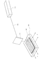
弾性基板101上に金属膜102を成膜する。また、弾性基板101の、金属膜102を成膜した面と反対側の面に有機材料103を付着させる(図1(A)参照)。有機材料103とは、EL材料であり、発光層の材料、電子注入層の材料、電子輸送層の材料、ホール注入層の材料、ホール輸送層の材料の少なくとも1つを含むものとする。なお弾性基板101と有機材料103との間にバッファ層を設けてもよい。弾性基板101として、外力を加えると変形するが、除荷すると元に戻る性質を有する基板であり、また、衝撃波を伝える材料である。
A
弾性基板101として、例えば、ゴム基板や樹脂基板等を用いればよい。ゴム基板を用いる場合の材料は、天然ゴムや合成ゴム等が挙げられる。
For example, a rubber substrate or a resin substrate may be used as the
合成ゴムとしては、アクリルゴム、アクリロニトリルブタジエンゴム(ニトリルゴム)、イソプレンゴム、ウレタンゴム、エチレンプロピレンゴム、エピクロルヒドリンゴム、クロロプレンゴム、シリコーンゴム、スチレンブタジエンゴム、ブタジエンゴム、フッ素ゴム、ポリイソブチレンゴム(ブチルゴム)等が挙げられる。 Synthetic rubbers include acrylic rubber, acrylonitrile butadiene rubber (nitrile rubber), isoprene rubber, urethane rubber, ethylene propylene rubber, epichlorohydrin rubber, chloroprene rubber, silicone rubber, styrene butadiene rubber, butadiene rubber, fluorine rubber, polyisobutylene rubber (butyl rubber). ) And the like.
樹脂基板を用いる場合の材料は、熱硬化性樹脂や熱可塑性樹脂等が挙げられる。 Examples of the material in the case of using a resin substrate include a thermosetting resin and a thermoplastic resin.
熱硬化性樹脂としては、フェノール樹脂、エポキシ樹脂、メラミン樹脂、尿素樹脂(ユリア樹脂)、不飽和ポリエステル樹脂、アルキド樹脂、ポリウレタン、熱硬化性ポリイミド等が挙げられる。 Examples of the thermosetting resin include phenol resin, epoxy resin, melamine resin, urea resin (urea resin), unsaturated polyester resin, alkyd resin, polyurethane, and thermosetting polyimide.
熱可塑性樹脂としては、汎用プラスチック、エンジニアリング・プラスチック、スーパーエンジニアリングプラスチック等が挙げられる。 Examples of the thermoplastic resin include general-purpose plastic, engineering plastic, and super engineering plastic.
汎用プラスチックとしては、ポリエチレン(高密度ポリエチレン、中密度ポリエチレン、低密度ポリエチレンを含む)、ポリプロピレン、ポリ塩化ビニル(ポリ塩化ビニリデンを含む)、ポリスチレン、ポリ酢酸ビニル、ポリテトラフルオロエチレン、ABS樹脂(アクリロニトリルブタジエンスチレン樹脂)AS樹脂、アクリル樹脂等が挙げられる General-purpose plastics include polyethylene (including high-density polyethylene, medium-density polyethylene, and low-density polyethylene), polypropylene, polyvinyl chloride (including polyvinylidene chloride), polystyrene, polyvinyl acetate, polytetrafluoroethylene, and ABS resin (acrylonitrile). Butadiene styrene resin) AS resin, acrylic resin, etc.
エンジニアリング・プラスチックとしては、ポリアミド(ナイロンを含む)、ポリアセタール、ポリカーボネート、変性ポリフェニレンエーテル、ポリブチレンテレフタレート、ポリエチレンテレフタレート、グラスファイバー強化ポリエチレンテレフタレート、環状ポリオレフィン等が挙げられる。 Examples of engineering plastics include polyamide (including nylon), polyacetal, polycarbonate, modified polyphenylene ether, polybutylene terephthalate, polyethylene terephthalate, glass fiber reinforced polyethylene terephthalate, and cyclic polyolefin.
スーパーエンジニアリングプラスチックとしては、ポリフェニレンスルファイド、ポリテトラフロロエチレン、ポリスルホン、ポリエーテルサルフォン、非晶ポリアリレート、液晶ポリマー、ポリエーテルエーテルケトン、熱可塑性ポリイミド、ポリアミドイミド等が挙げられる。 Examples of super engineering plastics include polyphenylene sulfide, polytetrafluoroethylene, polysulfone, polyethersulfone, amorphous polyarylate, liquid crystal polymer, polyetheretherketone, thermoplastic polyimide, and polyamideimide.
また、合成樹脂を用いた複合材料の一種として繊維強化プラスチックがあり、繊維強化プラスチックの代表的なものに、ガラス繊維強化プラスチック(GFRP)と炭素繊維強化プラスチック(CFRP)がある。 One type of composite material using synthetic resin is fiber reinforced plastic. Typical examples of fiber reinforced plastic include glass fiber reinforced plastic (GFRP) and carbon fiber reinforced plastic (CFRP).
なお、弾性基板101の厚さは10μm〜1mm、金属膜102の膜厚は1nm〜1μm、有機材料103の膜厚は10nm〜300nmにすればよい。
The
弾性基板101を転写対象基板104から数10μm〜数100μmの隙間をあけて有機材料103が付着している面が、転写対象基板104に向かい合うように固定する(図1(B)参照))。
The
転写対象基板104は、有機材料が表面に成膜されていると、有機材料103の一部である有機層111が飛び出した後、付着しやすいので有用である。
When the organic material is formed on the surface of the
このとき、有機材料103と転写対象基板104の間は、シール材107を使用し真空状態で封止する。こうすることで有機材料103を転写したときに転写された有機材料103の一部の膜厚が薄くなるのを防ぐことができ、また不純物の混入を防ぐことができる。真空状態では、平均自由行程が延びるため、転写される膜の分子が散乱されることなくまっすぐに進み、転写された有機材料103の一部の膜厚が薄くなるのを防ぐこと可能である。
At this time, between the
次いで、金属膜102に光照射、例えばレーザビーム105を照射する(図1(C)参照))。なお後述する図3中A−Bの断面図が図1(C)である。光源としてレーザが好適であるが、金属膜102を局所的に加熱して衝撃波が生じさせるものであれば、他の代替手段を適用してもよい。
Next, the
例えば、金属膜102にプローブを近接させてパルス放電(アーク放電)を生じさせ、局所的及び瞬間的に金属膜102を加熱して衝撃波を発生させてもよい。
For example, a probe may be brought close to the
レーザはQ−スイッチレーザや、その他のパルスレーザ、例えばエキシマレーザなどを使用するとよい。Q−スイッチレーザ光を照射すると、高エネルギー蓄積で金属膜102の表面は瞬間的に超高温に曝され(図2(A)参照)、レーザビーム105を照射する方向と逆方向に金属プラズマジェットを噴出し、その反作用として金属膜102中には衝撃波108が伝播する(図2(B)参照)。このときレーザビーム105のパワー分布を一様にすれば、衝撃波108の力も一様となる。
The laser may be a Q-switched laser or other pulsed laser such as an excimer laser. When the Q-switched laser beam is irradiated, the surface of the
金属膜102中を伝播する衝撃波は、裏面の弾性基板101の界面で膨張波となって反射し、金属膜102は瞬間的に変形する。この金属膜102の膨張は弾性基板101にまで伝わり、弾性基板101も瞬間的に変形する。
The shock wave propagating through the
これにより、弾性基板101上の、金属膜102が形成された面と反対側の面に付着していた有機材料103の一部である有機層111が高速で飛び出し、離れた転写対象基板104に転写される(図2(C)参照)。
As a result, the
弾性基板101及び転写対象基板104をX方向及びY方向に走査するステージ109に載せることで、金属膜102の全面に、レーザ発振器110から発振され、ミラー112によって反射されたレーザビーム105を照射することができる(図3参照)。
By placing the
また金属膜102を所望の形状に成膜しておくことで、金属膜102の存在しない領域は変形しないため有機材料103が転写されず、金属膜102が存在する領域では、転写対象基板104上に所望の形状の有機層111を転写することができる(図4(A)参照)。
In addition, by forming the
あるいは、有機材料103を所望の形状に成膜しておくと、所望の形状のまま有機層111が転写対象基板104に転写される(図4(B)参照)。
Alternatively, when the
また、有機材料103として、第1の有機材料103a及び第2の有機材料103bを積層して積層膜を形成しておき、積層膜を一度に転写対象基板104に転写して、転写対象基板104上に第2の有機層111bと第1の有機層111aの積層膜を形成してもよい(図5(A)参照)。また有機材料103を積層膜として形成し、図4(A)に示す方法(図5(B)参照)や図4(B)に示す方法(図5(C)参照)により、所望の形状の積層膜である有機層111を転写対象基板104上に形成してもよい。
Further, as the
例えば、図5(A)に示すように、第1の有機材料103aを発光層の材料、第2の有機材料103bを電子注入層の材料とすると、転写対象基板104上に、電子注入層である第2の有機層111bと発光層である第1の有機層111aを一度に形成することが可能である。
For example, as shown in FIG. 5A, when the first
以上に記載した成膜方法を用いて、発光素子を作製する方法を、図6(A)〜図6(F)を用いて以下に説明する。 A method for manufacturing a light-emitting element using the above-described film formation method is described below with reference to FIGS.
まず透光性を有する基板121上に、下地膜122を形成する。透光性を有する基板121は、例えばガラス基板や石英基板を用いればよい。また下地膜122は、酸化珪素膜、窒化珪素膜、酸素を含む窒化珪素膜、窒素を含む酸化珪素膜のいずれか1つ、あるいは、2つ以上を積層した積層膜を用いればよい。
First, the
下地膜122上に、島状半導体膜141、島状半導体膜142、島状半導体膜143を形成する。島状半導体膜141、島状半導体膜142、島状半導体膜143それぞれは、下地膜122上に半導体膜を成膜し、島状になるようにマスクを用いてエッチングすればよい。
Over the
半導体膜を形成する材料は、シランやゲルマンに代表される半導体材料を用いて気相成長法やスパッタリング法で作製される非晶質(アモルファス)半導体、該非晶質半導体を光エネルギーや熱エネルギーを利用して結晶化させた多結晶半導体、或いは微結晶(セミアモルファス若しくはマイクロクリスタルとも呼ばれる。以下「SAS」ともいう)半導体、有機材料を主成分とする半導体などを用いることができる。半導体膜はスパッタ法、LPCVD法、またはプラズマCVD法等により成膜することができる。 As a material for forming a semiconductor film, an amorphous semiconductor manufactured by vapor deposition or sputtering using a semiconductor material typified by silane or germane, and the amorphous semiconductor is subjected to light energy or thermal energy. A polycrystalline semiconductor which is crystallized by using, a microcrystalline (also referred to as semi-amorphous or microcrystal; hereinafter referred to as “SAS”) semiconductor, a semiconductor mainly containing an organic material, or the like can be used. The semiconductor film can be formed by a sputtering method, an LPCVD method, a plasma CVD method, or the like.
微結晶半導体膜は、ギブスの自由エネルギーを考慮すれば非晶質と単結晶の中間的な準安定状態に属するものである。すなわち、自由エネルギー的に安定な第3の状態を有する半導体であって、短距離秩序を持ち格子歪みを有する。柱状または針状結晶が基板表面に対して法線方向に成長している。微結晶半導体の代表例である微結晶シリコン(珪素)は、そのラマンスペクトルが単結晶シリコンを示す520cm−1よりも低波数側に、シフトしている。即ち、単結晶シリコンを示す520cm−1とアモルファスシリコンを示す480cm−1の間に微結晶シリコンのラマンスペクトルのピークがある。また、未結合手(ダングリングボンド)を終端するため水素またはハロゲンを少なくとも1原子%またはそれ以上含ませている。さらに、ヘリウム、アルゴン、クリプトン、ネオンなどの希ガス元素を含ませて格子歪みをさらに助長させることで、安定性が増し良好な微結晶半導体膜が得られる。 A microcrystalline semiconductor film belongs to a metastable state between amorphous and single crystal in consideration of Gibbs free energy. That is, it is a semiconductor having a third state that is stable in terms of free energy, and has a short-range order and lattice distortion. Columnar or needle-like crystals grow in the normal direction with respect to the substrate surface. Microcrystalline silicon (silicon) which is a typical example of a microcrystalline semiconductor has its Raman spectrum shifted to a lower wave number side than 520 cm −1 indicating single crystal silicon. That is, the peak of the Raman spectrum of microcrystalline silicon is between 520 cm −1 indicating single crystal silicon and 480 cm −1 indicating amorphous silicon. In addition, at least 1 atomic% or more of hydrogen or halogen is contained to terminate dangling bonds (dangling bonds). Further, by adding a rare gas element such as helium, argon, krypton, or neon to further promote lattice distortion, stability can be improved and a good microcrystalline semiconductor film can be obtained.
この微結晶半導体膜は、周波数が数十MHz〜数百MHzの高周波プラズマCVD法、または周波数が1GHz以上のマイクロ波プラズマCVD装置により形成することができる。代表的には、SiH4、Si2H6、SiH2Cl2、SiHCl3、SiCl4、SiF4などの水素化珪素を水素で希釈して形成することができる。また、水素化珪素及び水素に加え、ヘリウム、アルゴン、クリプトン、ネオンから選ばれた一種または複数種の希ガス元素で希釈して微結晶半導体膜を形成することができる。これらのときの水素化珪素に対して水素の流量比を5倍以上200倍以下、好ましくは50倍以上150倍以下、更に好ましくは100倍とする。 This microcrystalline semiconductor film can be formed by a high-frequency plasma CVD method with a frequency of several tens to several hundreds of MHz or a microwave plasma CVD apparatus with a frequency of 1 GHz or more. Typically, silicon hydride such as SiH 4 , Si 2 H 6 , SiH 2 Cl 2 , SiHCl 3 , SiCl 4 , and SiF 4 can be formed by diluting with hydrogen. In addition to silicon hydride and hydrogen, the microcrystalline semiconductor film can be formed by dilution with one or more kinds of rare gas elements selected from helium, argon, krypton, and neon. The flow rate ratio of hydrogen to silicon hydride at these times is 5 to 200 times, preferably 50 to 150 times, and more preferably 100 times.
アモルファス半導体としては、代表的には水素化アモルファスシリコン(非晶質珪素)、結晶性半導体としては代表的にはポリシリコン(多結晶珪素)などがあげられる。ポリシリコン(多結晶シリコン)には、800℃以上のプロセス温度を経て形成されるポリシリコンを主材料として用いた所謂高温ポリシリコンや、600℃以下のプロセス温度で形成されるポリシリコンを主材料として用いた所謂低温ポリシリコン、また結晶化を促進する元素などを用いて、非晶質シリコンを結晶化させたポリシリコンなどを含んでいる。もちろん、前述したように、微結晶半導体または半導体膜の一部に結晶相を含む半導体を用いることもできる。 A typical example of an amorphous semiconductor is hydrogenated amorphous silicon (amorphous silicon), and a typical example of a crystalline semiconductor is polysilicon (polycrystalline silicon). Polysilicon (polycrystalline silicon) is mainly made of so-called high-temperature polysilicon using polysilicon formed through a process temperature of 800 ° C. or higher as a main material, or polysilicon formed at a process temperature of 600 ° C. or lower. And so-called low-temperature polysilicon, and polysilicon obtained by crystallizing amorphous silicon using an element that promotes crystallization. Needless to say, as described above, a microcrystalline semiconductor or a semiconductor including a crystal phase in part of a semiconductor film can be used.
また、半導体の材料としてはシリコン(Si)、ゲルマニウム(Ge)などの単体のほかGaAs、InP、SiC、ZnSe、GaN、SiGeなどのような化合物半導体も用いることができる。また酸化物半導体である酸化亜鉛(ZnO)、酸化スズ(SnO2)、酸化マグネシウム亜鉛、酸化ガリウム、インジウム酸化物、及び上記酸化物半導体の複数より構成される酸化物半導体などを用いることができる。例えば、酸化亜鉛とインジウム酸化物と酸化ガリウムとから構成される酸化物半導体なども用いることができる。なお、酸化亜鉛を半導体膜に用いる場合、ゲート絶縁膜をY2O3、Al2O3、TiO2、それらの積層などを用いるとよく、ゲート電極、ソース電極、ドレイン電極としては、インジウム錫酸化物(Indium Tin Oxide:ITO)、金(Au)、チタン(Ti)などを用いるとよい。また、ZnOにInやGaなどを添加することもできる。 As a semiconductor material, a compound semiconductor such as GaAs, InP, SiC, ZnSe, GaN, or SiGe can be used in addition to a simple substance such as silicon (Si) or germanium (Ge). Alternatively, an oxide semiconductor such as zinc oxide (ZnO), tin oxide (SnO 2 ), magnesium zinc oxide, gallium oxide, indium oxide, and a plurality of the above oxide semiconductors can be used. . For example, an oxide semiconductor including zinc oxide, indium oxide, and gallium oxide can be used. Note that in the case where zinc oxide is used for the semiconductor film, Y 2 O 3 , Al 2 O 3 , TiO 2 , a stacked layer thereof, or the like may be used for the gate insulating film. An oxide (Indium Tin Oxide: ITO), gold (Au), titanium (Ti), or the like may be used. In addition, In, Ga, or the like can be added to ZnO.
半導体膜として、結晶性半導体膜を用いる場合、その結晶性半導体膜の作製方法は、種々の方法(レーザ結晶化法、熱結晶化法、またはニッケルなどの結晶化を助長する元素を用いた熱結晶化法等)を用いれば良い。また、SASである微結晶半導体膜をレーザ照射して結晶化し、結晶性を高めることもできる。結晶化を助長する元素を導入しない場合は、非晶質珪素膜にレーザ光を照射する前に、窒素雰囲気下500℃で1時間加熱することによって非晶質珪素膜の含有水素濃度を1×10²⁰atoms/cm3以下にまで放出させる。これは水素を多く含んだ非晶質珪素膜にレーザ光を照射すると非晶質珪素膜が破壊されてしまうからである。 When a crystalline semiconductor film is used as a semiconductor film, a crystalline semiconductor film can be manufactured by various methods (laser crystallization method, thermal crystallization method, or heat using an element that promotes crystallization such as nickel). A crystallization method or the like may be used. In addition, a microcrystalline semiconductor film which is a SAS can be crystallized by laser irradiation to increase crystallinity. In the case where an element for promoting crystallization is not introduced, the amorphous silicon film is heated at 500 ° C. for 1 hour in a nitrogen atmosphere before irradiating the amorphous silicon film with laser light, whereby the concentration of hydrogen contained in the amorphous silicon film is set to 1 ×. Release to 10 20 atoms / cm 3 or less. This is because the amorphous silicon film is destroyed when the amorphous silicon film containing a large amount of hydrogen is irradiated with laser light.
また、非晶質半導体膜を結晶化し、結晶性半導体膜を形成する結晶化工程で、非晶質半導体膜に結晶化を促進する元素(触媒元素、金属元素とも示す)を添加し、熱処理(550℃〜750℃で3分〜24時間)により結晶化を行ってもよい。結晶化を助長(促進)する元素としては、鉄(Fe)、ニッケル(Ni)、コバルト(Co)、ルテニウム(Ru)、ロジウム(Rh)、パラジウム(Pd)、オスミウム(Os)、イリジウム(Ir)、白金(Pt)、銅(Cu)及び金(Au)から選ばれた一種または複数種類を用いることができる。 In the crystallization step of crystallizing the amorphous semiconductor film to form the crystalline semiconductor film, an element (also referred to as a catalyst element or a metal element) that promotes crystallization is added to the amorphous semiconductor film, and heat treatment ( Crystallization may be carried out at 550 ° C. to 750 ° C. for 3 minutes to 24 hours. As elements that promote (promote) crystallization, iron (Fe), nickel (Ni), cobalt (Co), ruthenium (Ru), rhodium (Rh), palladium (Pd), osmium (Os), iridium (Ir) ), Platinum (Pt), copper (Cu) and gold (Au) can be used.
非晶質半導体膜への金属元素の導入の仕方としては、当該金属元素を非晶質半導体膜の表面またはその内部に存在させ得る手法であれば特に限定はなく、例えばスパッタ法、CVD法、プラズマ処理法(プラズマCVD法も含む)、吸着法、金属塩の溶液を添加する方法を使用することができる。このうち溶液を用いる方法は簡便であり、金属元素の濃度調整が容易であるという点で有用である。また、このとき非晶質半導体膜の表面の濡れ性を改善し、非晶質半導体膜の表面全体に水溶液を行き渡らせるため、酸素雰囲気中でのUV光の照射、熱酸化法、ヒドロキシラジカルを含むオゾン水または過酸化水素による処理等により、酸化膜を成膜することが望ましい。 The method for introducing the metal element into the amorphous semiconductor film is not particularly limited as long as the metal element can be present on the surface of the amorphous semiconductor film or inside the amorphous semiconductor film. For example, sputtering, CVD, A plasma treatment method (including a plasma CVD method), an adsorption method, or a method of adding a metal salt solution can be used. Among these, the method using a solution is simple and useful in that the concentration of the metal element can be easily adjusted. At this time, in order to improve the wettability of the surface of the amorphous semiconductor film and to spread the aqueous solution over the entire surface of the amorphous semiconductor film, irradiation with UV light in an oxygen atmosphere, thermal oxidation method, hydroxy radical It is desirable to form an oxide film by treatment with ozone water or hydrogen peroxide.
結晶化を助長する元素を結晶性半導体膜から除去するため、結晶性半導体膜に接して、不純物元素を含む半導体膜を形成し、ゲッタリングシンクとして機能させる。不純物元素としては、n型を付与する不純物元素、p型を付与する不純物元素や希ガス元素などを用いることができ、例えばリン(P)、窒素(N)、ヒ素(As)、アンチモン(Sb)、ビスマス(Bi)、ボロン(B)、ヘリウム(He)、ネオン(Ne)、アルゴン(Ar)、Kr(クリプトン)、Xe(キセノン)から選ばれた一種または複数種を用いることができる。結晶化を促進する元素を含む結晶性半導体膜に、希ガス元素を含む半導体膜を形成し、熱処理(550℃〜750℃で3分〜24時間)を行う。結晶性半導体膜中に含まれる結晶化を促進する元素は、希ガス元素を含む半導体膜中に移動し、結晶性半導体膜中の結晶化を促進する元素は除去される。その後、ゲッタリングシンクとなった希ガス元素を含む半導体膜を除去する。 In order to remove the element that promotes crystallization from the crystalline semiconductor film, a semiconductor film containing an impurity element is formed in contact with the crystalline semiconductor film and functions as a gettering sink. As the impurity element, an impurity element imparting n-type conductivity, an impurity element imparting p-type conductivity, a rare gas element, or the like can be used. For example, phosphorus (P), nitrogen (N), arsenic (As), antimony (Sb ), Bismuth (Bi), boron (B), helium (He), neon (Ne), argon (Ar), Kr (krypton), and Xe (xenon) can be used. A semiconductor film containing a rare gas element is formed over the crystalline semiconductor film containing the element that promotes crystallization, and heat treatment (at 550 ° C. to 750 ° C. for 3 minutes to 24 hours) is performed. The element that promotes crystallization contained in the crystalline semiconductor film moves into the semiconductor film containing a rare gas element, and the element that promotes crystallization in the crystalline semiconductor film is removed. After that, the semiconductor film containing a rare gas element that has become a gettering sink is removed.
非晶質半導体膜の結晶化は、熱処理とレーザ光照射による結晶化を組み合わせてもよく、熱処理やレーザ光照射を単独で、複数回行っても良い。 Crystallization of the amorphous semiconductor film may be a combination of heat treatment and crystallization by laser light irradiation, or may be performed multiple times by heat treatment or laser light irradiation alone.
また、結晶性半導体膜を、直接基板にプラズマ法により形成しても良い。また、プラズマ法を用いて、結晶性半導体膜を選択的に基板に形成してもよい。 Alternatively, the crystalline semiconductor film may be directly formed over the substrate by a plasma method. Alternatively, a crystalline semiconductor film may be selectively formed over the substrate by a plasma method.
有機材料を主成分とする半導体膜としては、他の元素と組み合わせて一定量の炭素または炭素の同素体(ダイヤモンドを除く)からなる物質を主成分とする半導体膜を用いることができる。具体的には、ペンタセン、テトラセン、チオフェンオリゴマ誘導体、フェニレン誘導体、フタロシアニン化合物、ポリアセチレン誘導体、ポリチオフェン誘導体、シアニン色素等が挙げられる。 As the semiconductor film containing an organic material as its main component, a semiconductor film containing as a main component a substance made of a certain amount of carbon or an allotrope of carbon (excluding diamond) in combination with other elements can be used. Specific examples include pentacene, tetracene, thiophen oligomer derivatives, phenylene derivatives, phthalocyanine compounds, polyacetylene derivatives, polythiophene derivatives, and cyanine dyes.
島状半導体膜141、島状半導体膜142、島状半導体膜143のそれぞれには、ゲート絶縁膜123を介して、ゲート電極145、ゲート電極146、ゲート電極147が形成されている(図6(A)参照)。
A
ゲート絶縁膜123、ゲート電極145、ゲート電極146、ゲート電極147は公知の構造、方法により作製すれば良い。例えば、ゲート絶縁膜123は、酸化珪素の単層膜または酸化珪素と窒化珪素との積層膜など、公知の構造で作製すればよい。
The
ゲート電極145、ゲート電極146、ゲート電極147はそれぞれ、CVD法やスパッタ法、液滴吐出法などを用い、Ag、Au、Cu、Ni、Pt、Pd、Ir、Rh、W、Al、Ta、Mo、Cd、Zn、Fe、Ti、Si、Ge、Zr、Baから選ばれた元素、または元素を主成分とする合金材料もしくは化合物材料で形成すればよい。また、リン等の不純物元素をドーピングした多結晶珪素膜に代表される半導体膜や、AgPdCu合金を用いてもよい。また、単層構造でも複数層の構造でもよい。
Each of the
島状半導体膜141、島状半導体膜142、島状半導体膜143それぞれに、ゲート電極145、ゲート電極146、ゲート電極147をマスクとして、一導電型を付与する不純物元素を添加してもよい。一導電型を付与する不純物元素として、n型を付与する不純物元素の場合には、リン(P)やヒ素(As)を用いればよく、p型を付与する不純物元素の場合には、ホウ素(B)を用いればよい。
An impurity element imparting one conductivity type may be added to the island-shaped
なお本実施の形態においては、トップゲートの薄膜トランジスタ(Thin Film Transistor:TFT)を形成する例を示したが、もちろんその他、ボトムゲートや公知の他の構造のトランジスタを用いても構わない。 Note that although an example in which a top gate thin film transistor (TFT) is formed has been described in this embodiment, it is needless to say that a bottom gate or a transistor having another known structure may be used.
ゲート絶縁膜123、ゲート電極145、ゲート電極146、ゲート電極147を覆って、絶縁膜124を形成する。絶縁膜124上に、島状半導体膜141に電気的に接続する電極151及び電極152、島状半導体膜142に電気的に接続する電極153及び電極154、島状半導体膜143に電気的に接続する電極154及び電極155を形成する(図6(B)参照)。
An insulating
絶縁膜124は、有機絶縁材料を用いて形成し、有機絶縁材料としては、アクリル、ポリイミド、ポリアミド、ポリイミドアミド、ベンゾシクロブテン等を使用することができる。
The insulating
また電極151、電極152、電極153、電極154、電極155はそれぞれ、ゲート電極145と同様にして形成すればよい。なお電極154は島状半導体膜142及び島状半導体膜143に電気的に接続されている。島状半導体膜142及び島状半導体膜143のいずれか一方はn型を付与する不純物元素、他方はp型を付与する不純物元素が添加されており、CMOS回路135を形成している。このCMOS回路135は駆動回路の基本構成となっている。
In addition, the
また島状半導体膜141には、n型を付与する不純物元素あるいはp型を付与する不純物元素が添加されており、TFT134が形成される。TFT134は画素回路を構成するものである。
Further, an impurity element imparting n-type conductivity or an impurity element imparting p-type conductivity is added to the island-shaped
次いで、絶縁膜124上に、TFT134の電極152と電気的に接続する電極127を形成する(図6(C)参照)。
Next, an
電極127は、発光素子137の第1の電極である。電極127が陽極である場合は、透明導電膜の材料は、酸化インジウム(In2O3)や酸化インジウム酸化スズ合金(In2O3―SnO2;ITO)などをスパッタ法や真空蒸着法などを用いて形成して用いることができる。酸化インジウム酸化亜鉛合金(In2O3―ZnO)を用いても良い。また、酸化亜鉛(ZnO)も適した材料であり、さらに可視光の透過率や導電率を高めるためにガリウム(Ga)を添加した酸化亜鉛(ZnO:Ga)などを用いることができる。
The
電極127を陰極とする場合には、アルミニウムなど仕事関数の低い材料の極薄膜を用いるか、そのような物質の薄膜と上述のような透明導電膜との積層構造を用いることによって作製することができる。
In the case where the
次いで、絶縁膜124及び電極127を覆って、有機絶縁材料を用いて絶縁膜131を形成する。また絶縁膜131を電極127の表面が露出しかつ電極127の端部を覆うように加工する。絶縁膜131の電極127の端部を覆う領域を、隔壁と呼ぶ(図6(D)参照)。CMOS回路135上には絶縁膜131は存在していなくてもよい。
Next, an insulating
次いで、絶縁膜131及び電極127上に、発光層128を形成する(図6(E)参照。発光層128は、図1(A)〜図1(C)、図2(A)〜図2(C)、図3、図4(A)〜図4(B)に示す工程を用いて形成すればよい。すなわち、発光層128として有機材料103を用い、転写対象基板104の代わりに、電極127上に、発光層128を転写させればよい。
Next, a light-emitting
発光層128の積層構造については特に限定されず、電子輸送性の高い物質を含む層または正孔輸送性の高い物質を含む層、電子注入性の高い物質を含む層、正孔注入性の高い物質を含む層、バイポーラ性(電子及び正孔の輸送性の高い物質)の物質を含む層等を適宜組み合わせて構成すればよい。
There is no particular limitation on the stacked structure of the light-emitting
なお本明細書では、発光層128は、発光層単層、あるいは、発光層、及び、正孔注入層、正孔輸送層、電子輸送層、電子注入層の少なくともいずれか1つとの積層を指す。
Note that in this specification, the light-emitting
例えば、発光層128として、正孔注入層、正孔輸送層、発光層、電子輸送層、電子注入層等を適宜組み合わせて構成することができる。本実施の形態では、発光層128は、正孔注入層、正孔輸送層、発光層、電子輸送層、電子注入層を有する構成について説明する。各層を構成する材料について以下に具体的に示す。
For example, the light-emitting
正孔注入層は、陽極に接して設けられ、正孔注入性の高い物質を含む層である。モリブデン酸化物やバナジウム酸化物、ルテニウム酸化物、タングステン酸化物、マンガン酸化物等を用いることができる。この他、フタロシアニン(略称:H2Pc)や銅フタロシアニン(CuPC)等のフタロシアニン系の化合物、4,4’−ビス[N−(4−ジフェニルアミノフェニル)−N−フェニルアミノ]ビフェニル(略称:DPAB)、4,4’−ビス(N−{4−[N−(3−メチルフェニル)−N−フェニルアミノ]フェニル}−N−フェニルアミノ)ビフェニル(略称:DNTPD)等の芳香族アミン化合物、或いはポリ(エチレンジオキシチオフェン)/ポリ(スチレンスルホン酸)(PEDOT/PSS)等の高分子等によっても正孔注入層を形成することができる。 The hole injection layer is a layer that is provided in contact with the anode and contains a substance having a high hole injection property. Molybdenum oxide, vanadium oxide, ruthenium oxide, tungsten oxide, manganese oxide, or the like can be used. In addition, phthalocyanine compounds such as phthalocyanine (abbreviation: H 2 Pc) and copper phthalocyanine (CuPC), 4,4′-bis [N- (4-diphenylaminophenyl) -N-phenylamino] biphenyl (abbreviation: DPAB), 4,4′-bis (N- {4- [N- (3-methylphenyl) -N-phenylamino] phenyl} -N-phenylamino) biphenyl (abbreviation: DNTPD) Alternatively, the hole injection layer can be formed by a polymer such as poly (ethylenedioxythiophene) / poly (styrenesulfonic acid) (PEDOT / PSS).
また、正孔注入層として、正孔輸送性の高い物質にアクセプター性物質を含有させた複合材料を用いることができる。なお、正孔輸送性の高い物質にアクセプター性物質を含有させたものを用いることにより、電極の仕事関数に依らず電極を形成する材料を選ぶことができる。つまり、電極127として仕事関数の大きい材料だけでなく、仕事関数の小さい材料を用いることができる。アクセプター性物質としては、7,7,8,8−テトラシアノ−2,3,5,6−テトラフルオロキノジメタン(略称:F4−TCNQ)、クロラニル等を挙げることができる。また、遷移金属酸化物を挙げることができる。また元素周期表における第4族乃至第8族に属する金属の酸化物を挙げることができる。具体的には、酸化バナジウム、酸化ニオブ、酸化タンタル、酸化クロム、酸化モリブデン、酸化タングステン、酸化マンガン、酸化レニウムは電子受容性が高いため好ましい。中でも特に、酸化モリブデンは大気中でも安定であり、吸湿性が低く、扱いやすいため好ましい。
For the hole injection layer, a composite material in which an acceptor substance is contained in a substance having a high hole-transport property can be used. Note that by using a substance having an acceptor substance contained in a substance having a high hole-transport property, a material for forming an electrode can be selected regardless of the work function of the electrode. That is, not only a material with a high work function but also a material with a low work function can be used for the
複合材料に用いる正孔輸送性の高い物質としては、芳香族アミン化合物、カルバゾール誘導体、芳香族炭化水素、高分子化合物(オリゴマー、デンドリマー、ポリマー等)など、種々の化合物を用いることができる。なお、複合材料に用いる有機化合物としては、正孔輸送性の高い有機化合物であることが好ましい。具体的には、10−6cm2/Vs以上の正孔移動度を有する物質であることが好ましい。但し、電子よりも正孔の輸送性の高い物質であれば、これら以外のものを用いてもよい。以下では、複合材料に用いることのできる有機化合物を具体的に列挙する。 As the substance having a high hole-transport property used for the composite material, various compounds such as an aromatic amine compound, a carbazole derivative, an aromatic hydrocarbon, and a high molecular compound (oligomer, dendrimer, polymer, and the like) can be used. Note that the organic compound used for the composite material is preferably an organic compound having a high hole-transport property. Specifically, a substance having a hole mobility of 10 −6 cm 2 / Vs or higher is preferable. Note that other than these substances, any substance that has a property of transporting more holes than electrons may be used. Below, the organic compound which can be used for a composite material is listed concretely.
例えば、芳香族アミン化合物としては、N,N’−ジ(p−トリル)−N,N’−ジフェニル−p−フェニレンジアミン(略称:DTDPPA)、4,4’−ビス[N−(4−ジフェニルアミノフェニル)−N−フェニルアミノ]ビフェニル(略称:DPAB)、4,4’−ビス(N−{4−[N−(3−メチルフェニル)−N−フェニルアミノ]フェニル}−N−フェニルアミノ)ビフェニル(略称:DNTPD)、1,3,5−トリス[N−(4−ジフェニルアミノフェニル)−N−フェニルアミノ]ベンゼン(略称:DPA3B)等を挙げることができる。 For example, as an aromatic amine compound, N, N′-di (p-tolyl) -N, N′-diphenyl-p-phenylenediamine (abbreviation: DTDPPA), 4,4′-bis [N- (4- Diphenylaminophenyl) -N-phenylamino] biphenyl (abbreviation: DPAB), 4,4′-bis (N- {4- [N- (3-methylphenyl) -N-phenylamino] phenyl} -N-phenyl Amino) biphenyl (abbreviation: DNTPD), 1,3,5-tris [N- (4-diphenylaminophenyl) -N-phenylamino] benzene (abbreviation: DPA3B), and the like can be given.
複合材料に用いることのできるカルバゾール誘導体としては、具体的には、3−[N−(9−フェニルカルバゾール−3−イル)−N−フェニルアミノ]−9−フェニルカルバゾール(略称:PCzPCA1)、3,6−ビス[N−(9−フェニルカルバゾール−3−イル)−N−フェニルアミノ]−9−フェニルカルバゾール(略称:PCzPCA2)、3−[N−(1−ナフチル)−N−(9−フェニルカルバゾール−3−イル)アミノ]−9−フェニルカルバゾール(略称:PCzPCN1)等を挙げることができる。 Specific examples of the carbazole derivative that can be used for the composite material include 3- [N- (9-phenylcarbazol-3-yl) -N-phenylamino] -9-phenylcarbazole (abbreviation: PCzPCA1), 3 , 6-Bis [N- (9-phenylcarbazol-3-yl) -N-phenylamino] -9-phenylcarbazole (abbreviation: PCzPCA2), 3- [N- (1-naphthyl) -N- (9- Phenylcarbazol-3-yl) amino] -9-phenylcarbazole (abbreviation: PCzPCN1) and the like.
また、複合材料に用いることのできるカルバゾール誘導体としては、他に、4,4’−ジ(N−カルバゾリル)ビフェニル(略称:CBP)、1,3,5−トリス[4−(N−カルバゾリル)フェニル]ベンゼン(略称:TCPB)、9−[4−(10−フェニル−9−アントリル)フェニル]−9H−カルバゾール(略称:CzPA)、1,4−ビス[4−(N−カルバゾリル)フェニル]−2,3,5,6−テトラフェニルベンゼン等を用いることができる。 As other carbazole derivatives that can be used for the composite material, 4,4′-di (N-carbazolyl) biphenyl (abbreviation: CBP), 1,3,5-tris [4- (N-carbazolyl) Phenyl] benzene (abbreviation: TCPB), 9- [4- (10-phenyl-9-anthryl) phenyl] -9H-carbazole (abbreviation: CzPA), 1,4-bis [4- (N-carbazolyl) phenyl] -2,3,5,6-tetraphenylbenzene and the like can be used.
また、複合材料に用いることのできる芳香族炭化水素としては、例えば、2−tert−ブチル−9,10−ジ(2−ナフチル)アントラセン(略称:t−BuDNA)、2−tert−ブチル−9,10−ジ(1−ナフチル)アントラセン、9,10−ビス(3,5−ジフェニルフェニル)アントラセン(略称:DPPA)、2−tert−ブチル−9,10−ビス(4−フェニルフェニル)アントラセン(略称:t−BuDBA)、9,10−ジ(2−ナフチル)アントラセン(略称:DNA)、9,10−ジフェニルアントラセン(略称:DPAnth)、2−tert−ブチルアントラセン(略称:t−BuAnth)、9,10−ビス(4−メチル−1−ナフチル)アントラセン(略称:DMNA)、2−tert−ブチル−9,10−ビス[2−(1−ナフチル)フェニル]アントラセン、9,10−ビス[2−(1−ナフチル)フェニル]アントラセン、2,3,6,7−テトラメチル−9,10−ジ(1−ナフチル)アントラセン、2,3,6,7−テトラメチル−9,10−ジ(2−ナフチル)アントラセン、9,9’−ビアントリル、10,10’−ジフェニル−9,9’−ビアントリル、10,10’−ビス(2−フェニルフェニル)−9,9’−ビアントリル、10,10’−ビス[(2,3,4,5,6−ペンタフェニル)フェニル]−9,9’−ビアントリル、アントラセン、テトラセン、ルブレン、ペリレン、2,5,8,11−テトラ(tert−ブチル)ペリレン等が挙げられる。また、この他、ペンタセン、コロネン等も用いることができる。このように、1×10−6cm2/Vs以上の正孔移動度を有し、炭素数14〜42である芳香族炭化水素を用いることがより好ましい。 Examples of aromatic hydrocarbons that can be used for the composite material include 2-tert-butyl-9,10-di (2-naphthyl) anthracene (abbreviation: t-BuDNA), 2-tert-butyl-9. , 10-di (1-naphthyl) anthracene, 9,10-bis (3,5-diphenylphenyl) anthracene (abbreviation: DPPA), 2-tert-butyl-9,10-bis (4-phenylphenyl) anthracene ( Abbreviations: t-BuDBA), 9,10-di (2-naphthyl) anthracene (abbreviation: DNA), 9,10-diphenylanthracene (abbreviation: DPAnth), 2-tert-butylanthracene (abbreviation: t-BuAnth), 9,10-bis (4-methyl-1-naphthyl) anthracene (abbreviation: DMNA), 2-tert-butyl-9, 0-bis [2- (1-naphthyl) phenyl] anthracene, 9,10-bis [2- (1-naphthyl) phenyl] anthracene, 2,3,6,7-tetramethyl-9,10-di (1 -Naphthyl) anthracene, 2,3,6,7-tetramethyl-9,10-di (2-naphthyl) anthracene, 9,9'-bianthryl, 10,10'-diphenyl-9,9'-bianthryl, 10 , 10′-bis (2-phenylphenyl) -9,9′-bianthryl, 10,10′-bis [(2,3,4,5,6-pentaphenyl) phenyl] -9,9′-bianthryl, Anthracene, tetracene, rubrene, perylene, 2,5,8,11-tetra (tert-butyl) perylene and the like can be mentioned. In addition, pentacene, coronene, and the like can also be used. Thus, it is more preferable to use an aromatic hydrocarbon having a hole mobility of 1 × 10 −6 cm 2 / Vs or more and having 14 to 42 carbon atoms.
なお、複合材料に用いることのできる芳香族炭化水素は、ビニル骨格を有していてもよい。ビニル基を有している芳香族炭化水素としては、例えば、4,4’−ビス(2,2−ジフェニルビニル)ビフェニル(略称:DPVBi)、9,10−ビス[4−(2,2−ジフェニルビニル)フェニル]アントラセン(略称:DPVPA)等が挙げられる。 Note that the aromatic hydrocarbon that can be used for the composite material may have a vinyl skeleton. As the aromatic hydrocarbon having a vinyl group, for example, 4,4′-bis (2,2-diphenylvinyl) biphenyl (abbreviation: DPVBi), 9,10-bis [4- (2,2- Diphenylvinyl) phenyl] anthracene (abbreviation: DPVPA) and the like.
また、ポリ(N−ビニルカルバゾール)(略称:PVK)やポリ(4−ビニルトリフェニルアミン)(略称:PVTPA)、ポリ[N−(4−{N’−[4−(4−ジフェニルアミノ)フェニル]フェニル−N’−フェニルアミノ}フェニル)メタクリルアミド](略称:PTPDMA)ポリ[N,N’−ビス(4−ブチルフェニル)−N,N’−ビス(フェニル)ベンジジン](略称:Poly−TPD)等の高分子化合物を用いることもできる。 In addition, poly (N-vinylcarbazole) (abbreviation: PVK), poly (4-vinyltriphenylamine) (abbreviation: PVTPA), poly [N- (4- {N ′-[4- (4-diphenylamino)] Phenyl] phenyl-N′-phenylamino} phenyl) methacrylamide] (abbreviation: PTPDMA) poly [N, N′-bis (4-butylphenyl) -N, N′-bis (phenyl) benzidine] (abbreviation: Poly High molecular compounds such as -TPD) can also be used.
正孔輸送層は、正孔輸送性の高い物質を含む層である。正孔輸送性の高い物質としては、例えば、4,4’−ビス[N−(1−ナフチル)−N−フェニルアミノ]ビフェニル(略称:NPB)やN,N’−ビス(3−メチルフェニル)−N,N’−ジフェニル−[1,1’−ビフェニル]−4,4’−ジアミン(略称:TPD)、4,4’,4’’−トリス(N,N−ジフェニルアミノ)トリフェニルアミン(略称:TDATA)、4,4’,4’’−トリス[N−(3−メチルフェニル)−N−フェニルアミノ]トリフェニルアミン(略称:MTDATA)、4,4’−ビス[N−(スピロ−9,9’−ビフルオレン−2−イル)−N―フェニルアミノ]ビフェニル(略称:BSPB)などの芳香族アミン化合物等を用いることができる。ここに述べた物質は、主に10−6cm2/Vs以上の正孔移動度を有する物質である。但し、電子よりも正孔の輸送性の高い物質であれば、これら以外のものを用いてもよい。なお、正孔輸送性の高い物質を含む層は、単層のものだけでなく、上記物質からなる層が二層以上積層したものとしてもよい。 The hole transport layer is a layer containing a substance having a high hole transport property. Examples of the substance having a high hole-transport property include 4,4′-bis [N- (1-naphthyl) -N-phenylamino] biphenyl (abbreviation: NPB) and N, N′-bis (3-methylphenyl). ) -N, N′-diphenyl- [1,1′-biphenyl] -4,4′-diamine (abbreviation: TPD), 4,4 ′, 4 ″ -tris (N, N-diphenylamino) triphenyl Amine (abbreviation: TDATA), 4,4 ′, 4 ″ -tris [N- (3-methylphenyl) -N-phenylamino] triphenylamine (abbreviation: MTDATA), 4,4′-bis [N— An aromatic amine compound such as (spiro-9,9′-bifluoren-2-yl) -N-phenylamino] biphenyl (abbreviation: BSPB) can be used. The substances described here are mainly substances having a hole mobility of 10 −6 cm 2 / Vs or higher. Note that other than these substances, any substance that has a property of transporting more holes than electrons may be used. Note that the layer containing a substance having a high hole-transport property is not limited to a single layer, and two or more layers containing the above substances may be stacked.
また、正孔輸送層として、ポリ(N−ビニルカルバゾール)(略称:PVK)やポリ(4−ビニルトリフェニルアミン)(略称:PVTPA)等の高分子化合物を用いることもできる。 Alternatively, a high molecular compound such as poly (N-vinylcarbazole) (abbreviation: PVK) or poly (4-vinyltriphenylamine) (abbreviation: PVTPA) can be used for the hole-transporting layer.
発光層は、発光性の物質を含む層である。発光層の種類としては、発光中心物質を主成分とするいわゆる単膜の発光層であっても、ホスト材料中に発光中心材料を分散するいわゆるホスト−ゲスト型の発光層であってもどちらでも構わない。 The light emitting layer is a layer containing a light emitting substance. The type of the light-emitting layer may be a so-called single-layer light-emitting layer mainly composed of an emission center material, or a so-called host-guest type light-emitting layer in which the emission center material is dispersed in the host material. I do not care.
用いられる発光中心材料に制限は無く、公知の蛍光又は燐光を発する材料を用いることができる。蛍光発光性材料としては、例えばN,N’−ビス[4−(9H−カルバゾール−9−イル)フェニル]−N,N’−ジフェニルスチルベン−4,4’−ジアミン(略称:YGA2S)、4−(9H−カルバゾール−9−イル)−4’−(10−フェニル−9−アントリル)トリフェニルアミン(略称:YGAPA)、等の他、発光波長が450nm以上の4−(9H−カルバゾール−9−イル)−4’−(9,10−ジフェニル−2−アントリル)トリフェニルアミン(略称:2YGAPPA)、N,9−ジフェニル−N−[4−(10−フェニル−9−アントリル)フェニル]−9H−カルバゾール−3−アミン(略称:PCAPA)、ペリレン、2,5,8,11−テトラ−tert−ブチルペリレン(略称:TBP)、4−(10−フェニル−9−アントリル)−4’−(9−フェニル−9H−カルバゾール−3−イル)トリフェニルアミン(略称:PCBAPA)、N,N’’−(2−tert−ブチルアントラセン−9,10−ジイルジ−4,1−フェニレン)ビス[N,N’,N’−トリフェニル−1,4−フェニレンジアミン](略称:DPABPA)、N,9−ジフェニル−N−[4−(9,10−ジフェニル−2−アントリル)フェニル]−9H−カルバゾール−3−アミン(略称:2PCAPPA)、N−[4−(9,10−ジフェニル−2−アントリル)フェニル]−N,N’,N’−トリフェニル−1,4−フェニレンジアミン(略称:2DPAPPA)、N,N,N’,N’,N’’,N’’,N’’’,N’’’−オクタフェニルジベンゾ[g,p]クリセン−2,7,10,15−テトラアミン(略称:DBC1)、クマリン30、N−(9,10−ジフェニル−2−アントリル)−N,9−ジフェニル−9H−カルバゾール−3−アミン(略称:2PCAPA)、N−[9,10−ビス(1,1’−ビフェニル−2−イル)−2−アントリル]−N,9−ジフェニル−9H−カルバゾール−3−アミン(略称:2PCABPhA)、N−(9,10−ジフェニル−2−アントリル)−N,N’,N’−トリフェニル−1,4−フェニレンジアミン(略称:2DPAPA)、N−[9,10−ビス(1,1’−ビフェニル−2−イル)−2−アントリル]−N,N’,N’−トリフェニル−1,4−フェニレンジアミン(略称:2DPABPhA)、9,10−ビス(1,1’−ビフェニル−2−イル)−N−[4−(9H−カルバゾール−9−イル)フェニル]−N−フェニルアントラセン−2−アミン(略称:2YGABPhA)、N,N,9−トリフェニルアントラセン−9−アミン(略称:DPhAPhA)クマリン545T、N,N’−ジフェニルキナクリドン、(略称:DPQd)、ルブレン、5,12−ビス(1,1’−ビフェニル−4−イル)−6,11−ジフェニルテトラセン(略称:BPT)、2−(2−{2−[4−(ジメチルアミノ)フェニル]エテニル}−6−メチル−4H−ピラン−4−イリデン)プロパンジニトリル(略称:DCM1)、2−{2−メチル−6−[2−(2,3,6,7−テトラヒドロ−1H,5H−ベンゾ[ij]キノリジン−9−イル)エテニル]−4H−ピラン−4−イリデン}プロパンジニトリル(略称:DCM2)、N,N,N’,N’−テトラキス(4−メチルフェニル)テトラセン−5,11−ジアミン(略称:p−mPhTD)、7,14−ジフェニル−N,N,N’,N’−テトラキス(4−メチルフェニル)アセナフト[1,2−a]フルオランテン−3,10−ジアミン(略称:p−mPhAFD)、2−{2−イソプロピル−6−[2−(1,1,7,7−テトラメチル−2,3,6,7−テトラヒドロ−1H,5H−ベンゾ[ij]キノリジン−9−イル)エテニル]−4H−ピラン−4−イリデン}プロパンジニトリル(略称:DCJTI)、2−{2−tert−ブチル−6−[2−(1,1,7,7−テトラメチル−2,3,6,7−テトラヒドロ−1H,5H−ベンゾ[ij]キノリジン−9−イル)エテニル]−4H−ピラン−4−イリデン}プロパンジニトリル(略称:DCJTB)、2−(2,6−ビス{2−[4−(ジメチルアミノ)フェニル]エテニル}−4H−ピラン−4−イリデン)プロパンジニトリル(略称:BisDCM)、2−{2,6−ビス[2−(8−メトキシ−1,1,7,7−テトラメチル−2,3,6,7−テトラヒドロ−1H,5H−ベンゾ[ij]キノリジン−9−イル)エテニル]−4H−ピラン−4−イリデン}プロパンジニトリル(略称:BisDCJTM)などが挙げられる。燐光発光性材料としては、例えば、ビス[2−(4’,6’−ジフルオロフェニル)ピリジナト−N,C2’]イリジウム(III)テトラキス(1−ピラゾリル)ボラート(略称:FIr6)、の他、発光波長が470nm〜500nmの範囲にある、ビス[2−(4’,6’−ジフルオロフェニル)ピリジナト−N,C2’]イリジウム(III)ピコリナート(略称:FIrpic)、ビス[2−(3’,5’−ビストリフルオロメチルフェニル)ピリジナト−N,C2’]イリジウム(III)ピコリナート(略称:Ir(CF3ppy)2(pic))、ビス[2−(4’,6’−ジフルオロフェニル)ピリジナト−N,C2’]イリジウム(III)アセチルアセトナート(略称:FIracac)、発光波長が500nm(緑色発光)以上のトリス(2−フェニルピリジナト)イリジウム(III)(略称:Ir(ppy)3)、ビス(2−フェニルピリジナト)イリジウム(III)アセチルアセトナート(略称:Ir(ppy)2(acac))、トリス(アセチルアセトナト)(モノフェナントロリン)テルビウム(III)(略称:Tb(acac)3(Phen))、ビス(ベンゾ[h]キノリナト)イリジウム(III)アセチルアセトナート(略称:Ir(bzq)2(acac))、ビス(2,4−ジフェニル−1,3−オキサゾラト−N,C2’)イリジウム(III)アセチルアセトナート(略称:Ir(dpo)2(acac))、ビス[2−(4’−パーフルオロフェニルフェニル)ピリジナト]イリジウム(III)アセチルアセトナート(略称:Ir(p−PF−ph)2(acac))、ビス(2−フェニルベンゾチアゾラト−N,C2’)イリジウム(III)アセチルアセトナート(略称:Ir(bt)2(acac))、ビス[2−(2’−ベンゾ[4,5−α]チエニル)ピリジナト−N,C3’]イリジウム(III)アセチルアセトナート(略称:Ir(btp)2(acac))、ビス(1−フェニルイソキノリナト−N,C2’)イリジウム(III)アセチルアセトナート(略称:Ir(piq)2(acac))、(アセチルアセトナト)ビス[2,3−ビス(4−フルオロフェニル)キノキサリナト]イリジウム(III)(略称:Ir(Fdpq)2(acac))、(アセチルアセトナト)ビス(2,3,5−トリフェニルピラジナト)イリジウム(III)(略称:Ir(tppr)2(acac))、2,3,7,8,12,13,17,18−オクタエチル−21H,23H−ポルフィリン白金(II)(略称:PtOEP)、トリス(1,3−ジフェニル−1,3−プロパンジオナト)(モノフェナントロリン)ユーロピウム(III)(略称:Eu(DBM)3(Phen))、トリス[1−(2−テノイル)−3,3,3−トリフルオロアセトナト](モノフェナントロリン)ユーロピウム(III)(略称:Eu(TTA)3(Phen))等が挙げられる。以上のような材料又は他の公知の材料の中から、各々の発光素子における発光色を考慮し選択すれば良い。 There is no restriction | limiting in the luminescent center material used, The material which emits well-known fluorescence or phosphorescence can be used. As a fluorescent material, for example, N, N′-bis [4- (9H-carbazol-9-yl) phenyl] -N, N′-diphenylstilbene-4,4′-diamine (abbreviation: YGA2S), 4 -(9H-carbazol-9-yl) -4 '-(10-phenyl-9-anthryl) triphenylamine (abbreviation: YGAPA), etc., and 4- (9H-carbazole-9 having an emission wavelength of 450 nm or more -Yl) -4 '-(9,10-diphenyl-2-anthryl) triphenylamine (abbreviation: 2YGAPPA), N, 9-diphenyl-N- [4- (10-phenyl-9-anthryl) phenyl]- 9H-carbazol-3-amine (abbreviation: PCAPA), perylene, 2,5,8,11-tetra-tert-butylperylene (abbreviation: TBP), 4- (10-phenyl) 9-anthryl) -4 ′-(9-phenyl-9H-carbazol-3-yl) triphenylamine (abbreviation: PCBAPA), N, N ″-(2-tert-butylanthracene-9,10-diyldi- 4,1-phenylene) bis [N, N ′, N′-triphenyl-1,4-phenylenediamine] (abbreviation: DPABPA), N, 9-diphenyl-N- [4- (9,10-diphenyl-) 2-anthryl) phenyl] -9H-carbazol-3-amine (abbreviation: 2PCAPPA), N- [4- (9,10-diphenyl-2-anthryl) phenyl] -N, N ′, N′-triphenyl- 1,4-phenylenediamine (abbreviation: 2DPAPPA), N, N, N ′, N ′, N ″, N ″, N ′ ″, N ′ ″-octaphenyldibenzo [g, p] chrysene- 2,7,10,15-te Laamine (abbreviation: DBC1), Coumarin 30, N- (9,10-diphenyl-2-anthryl) -N, 9-diphenyl-9H-carbazol-3-amine (abbreviation: 2PCAPA), N- [9,10- Bis (1,1′-biphenyl-2-yl) -2-anthryl] -N, 9-diphenyl-9H-carbazol-3-amine (abbreviation: 2PCABPhA), N- (9,10-diphenyl-2-anthryl) ) -N, N ′, N′-triphenyl-1,4-phenylenediamine (abbreviation: 2DPAPA), N- [9,10-bis (1,1′-biphenyl-2-yl) -2-anthryl] -N, N ', N'-triphenyl-1,4-phenylenediamine (abbreviation: 2DPABPhA), 9,10-bis (1,1'-biphenyl-2-yl) -N- [4- (9H- Carbazo Ru-9-yl) phenyl] -N-phenylanthracen-2-amine (abbreviation: 2YGABPhA), N, N, 9-triphenylanthracen-9-amine (abbreviation: DPhAPhA) coumarin 545T, N, N′-diphenyl Quinacridone, (abbreviation: DPQd), rubrene, 5,12-bis (1,1′-biphenyl-4-yl) -6,11-diphenyltetracene (abbreviation: BPT), 2- (2- {2- [4 -(Dimethylamino) phenyl] ethenyl} -6-methyl-4H-pyran-4-ylidene) propanedinitrile (abbreviation: DCM1), 2- {2-methyl-6- [2- (2,3,6,6) 7-tetrahydro-1H, 5H-benzo [ij] quinolizin-9-yl) ethenyl] -4H-pyran-4-ylidene} propanedinitrile (abbreviation: DCM2), , N, N ′, N′-tetrakis (4-methylphenyl) tetracene-5,11-diamine (abbreviation: p-mPhTD), 7,14-diphenyl-N, N, N ′, N′-tetrakis (4 -Methylphenyl) acenaphtho [1,2-a] fluoranthene-3,10-diamine (abbreviation: p-mPhAFD), 2- {2-isopropyl-6- [2- (1,1,7,7-tetramethyl) -2,3,6,7-tetrahydro-1H, 5H-benzo [ij] quinolizin-9-yl) ethenyl] -4H-pyran-4-ylidene} propanedinitrile (abbreviation: DCJTI), 2- {2- tert-Butyl-6- [2- (1,1,7,7-tetramethyl-2,3,6,7-tetrahydro-1H, 5H-benzo [ij] quinolizin-9-yl) ethenyl] -4H- Piran-4-i Den} propanedinitrile (abbreviation: DCJTB), 2- (2,6-bis {2- [4- (dimethylamino) phenyl] ethenyl} -4H-pyran-4-ylidene) propanedinitrile (abbreviation: BisDCM) 2- {2,6-bis [2- (8-methoxy-1,1,7,7-tetramethyl-2,3,6,7-tetrahydro-1H, 5H-benzo [ij] quinolidine-9- Yl) ethenyl] -4H-pyran-4-ylidene} propanedinitrile (abbreviation: BisDCJTM). Examples of the phosphorescent material include bis [2- (4 ′, 6′-difluorophenyl) pyridinato-N, C 2 ′ ] iridium (III) tetrakis (1-pyrazolyl) borate (abbreviation: FIr6), and the like. , Bis [2- (4 ′, 6′-difluorophenyl) pyridinato-N, C 2 ′ ] iridium (III) picolinate (abbreviation: FIrpic), bis [2- ( 3 ′, 5′-bistrifluoromethylphenyl) pyridinato-N, C 2 ′ ] iridium (III) picolinate (abbreviation: Ir (CF 3 ppy) 2 (pic)), bis [2- (4 ′, 6′- difluorophenyl) pyridinato -N, C 2 '] iridium (III) acetylacetonate (abbreviation: FIracac), emission wavelength 500 nm (green emission) Tris upper (2-phenylpyridinato) iridium (III) (abbreviation: Ir (ppy) 3), bis (2-phenylpyridinato) iridium (III) acetylacetonate (abbreviation: Ir (ppy) 2 ( acac)), tris (acetylacetonato) (monophenanthroline) terbium (III) (abbreviation: Tb (acac) 3 (Phen)), bis (benzo [h] quinolinato) iridium (III) acetylacetonate (abbreviation: Ir (Bzq) 2 (acac)), bis (2,4-diphenyl-1,3-oxazolate-N, C 2 ′ ) iridium (III) acetylacetonate (abbreviation: Ir (dpo) 2 (acac)), bis [2- (4′-perfluorophenylphenyl) pyridinato] iridium (III) acetylacetonate ( Abbreviations: Ir (p-PF-ph) 2 (acac)), bis (2-phenylbenzothiazolate-N, C 2 ′ ) iridium (III) acetylacetonate (abbreviation: Ir (bt) 2 (acac) ), Bis [2- (2′-benzo [4,5-α] thienyl) pyridinato-N, C 3 ′ ] iridium (III) acetylacetonate (abbreviation: Ir (btp) 2 (acac)), bis ( 1-phenylisoquinolinato-N, C 2 ′ ) iridium (III) acetylacetonate (abbreviation: Ir (piq) 2 (acac)), (acetylacetonato) bis [2,3-bis (4-fluorophenyl) ) Quinoxalinato] iridium (III) (abbreviation: Ir (Fdpq) 2 (acac)), (acetylacetonato) bis (2,3,5-triphenylpyrazinato) irid Um (III) (abbreviation: Ir (tppr) 2 (acac)), 2,3,7,8,12,13,17,18-octaethyl-21H, 23H-porphyrin platinum (II) (abbreviation: PtOEP), Tris (1,3-diphenyl-1,3-propanedionate) (monophenanthroline) europium (III) (abbreviation: Eu (DBM) 3 (Phen)), tris [1- (2-thenoyl) -3,3 , 3-trifluoroacetonato] (monophenanthroline) europium (III) (abbreviation: Eu (TTA) 3 (Phen)) and the like. What is necessary is just to select in consideration of the luminescent color in each light emitting element from the above materials or other known materials.
ホスト材料を用いる場合は、例えばトリス(8−キノリノラト)アルミニウム(III)(略称:Alq)、トリス(4−メチル−8−キノリノラト)アルミニウム(III)(略称:Almq3)、ビス(10−ヒドロキシベンゾ[h]キノリナト)ベリリウム(II)(略称:BeBq2)、ビス(2−メチル−8−キノリノラト)(4−フェニルフェノラト)アルミニウム(III)(略称:BAlq)、ビス(8−キノリノラト)亜鉛(II)(略称:Znq)、ビス[2−(2−ベンゾオキサゾリル)フェノラト]亜鉛(II)(略称:ZnPBO)、ビス[2−(2−ベンゾチアゾリル)フェノラト]亜鉛(II)(略称:ZnBTZ)などの金属錯体、2−(4−ビフェニリル)−5−(4−tert−ブチルフェニル)−1,3,4−オキサジアゾール(略称:PBD)、1,3−ビス[5−(p−tert−ブチルフェニル)−1,3,4−オキサジアゾール−2−イル]ベンゼン(略称:OXD−7)、3−(4−ビフェニリル)−4−フェニル−5−(4−tert−ブチルフェニル)−1,2,4−トリアゾール(略称:TAZ)、2,2’,2’’−(1,3,5−ベンゼントリイル)トリス(1−フェニル−1H−ベンゾイミダゾール)(略称:TPBI)、バソフェナントロリン(略称:BPhen)、バソキュプロイン(略称:BCP)、9−[4−(5−フェニル−1,3,4−オキサジアゾール−2−イル)フェニル]−9H−カルバゾール(略称:CO11)などの複素環化合物、NPB(またはα−NPD)、TPD、BSPBなどの芳香族アミン化合物が挙げられる。また、アントラセン誘導体、フェナントレン誘導体、ピレン誘導体、クリセン誘導体、ジベンゾ[g,p]クリセン誘導体等の縮合多環芳香族化合物が挙げられ、具体的には、9,10−ジフェニルアントラセン(略称:DPAnth)、N,N−ジフェニル−9−[4−(10−フェニル−9−アントリル)フェニル]−9H−カルバゾール−3−アミン(略称:CzA1PA)、4−(10−フェニル−9−アントリル)トリフェニルアミン(略称:DPhPA)、4−(9H−カルバゾール−9−イル)−4’−(10−フェニル−9−アントリル)トリフェニルアミン(略称:YGAPA)、N,9−ジフェニル−N−[4−(10−フェニル−9−アントリル)フェニル]−9H−カルバゾール−3−アミン(略称:PCAPA)、N,9−ジフェニル−N−{4−[4−(10−フェニル−9−アントリル)フェニル]フェニル}−9H−カルバゾール−3−アミン(略称:PCAPBA)、N,9−ジフェニル−N−(9,10−ジフェニル−2−アントリル)−9H−カルバゾール−3−アミン(略称:2PCAPA)、6,12−ジメトキシ−5,11−ジフェニルクリセン、N,N,N’,N’,N’’,N’’,N’’’,N’’’−オクタフェニルジベンゾ[g,p]クリセン−2,7,10,15−テトラアミン(略称:DBC1)、9−[4−(10−フェニル−9−アントリル)フェニル]−9H−カルバゾール(略称:CzPA)、3,6−ジフェニル−9−[4−(10−フェニル−9−アントリル)フェニル]−9H−カルバゾール(略称:DPCzPA)、9,10−ビス(3,5−ジフェニルフェニル)アントラセン(略称:DPPA)、9,10−ジ(2−ナフチル)アントラセン(略称:DNA)、2−tert−ブチル−9,10−ジ(2−ナフチル)アントラセン(略称:t−BuDNA)、9,9’−ビアントリル(略称:BANT)、9,9’−(スチルベン−3,3’−ジイル)ジフェナントレン(略称:DPNS)、9,9’−(スチルベン−4,4’−ジイル)ジフェナントレン(略称:DPNS2)、3,3’,3’’−(ベンゼン−1,3,5−トリイル)トリピレン(略称:TPB3)などを挙げることができる。これら及び公知の物質の中から、各々が分散する発光中心物質のエネルギーギャップ(燐光発光の場合は三重項エネルギー)より大きなエネルギーギャップ(三重項エネルギー)を有する物質を有し、且つ各々の層が有すべき輸送性に合致した輸送性を示す物質を選択すればよい。 In the case of using a host material, for example, tris (8-quinolinolato) aluminum (III) (abbreviation: Alq), tris (4-methyl-8-quinolinolato) aluminum (III) (abbreviation: Almq 3 ), bis (10-hydroxy) Benzo [h] quinolinato) beryllium (II) (abbreviation: BeBq 2 ), bis (2-methyl-8-quinolinolato) (4-phenylphenolato) aluminum (III) (abbreviation: BAlq), bis (8-quinolinolato) Zinc (II) (abbreviation: Znq), bis [2- (2-benzoxazolyl) phenolato] zinc (II) (abbreviation: ZnPBO), bis [2- (2-benzothiazolyl) phenolato] zinc (II) ( Abbreviations: ZnBTZ) and other metal complexes, 2- (4-biphenylyl) -5- (4-tert-butylphenyl)- 1,3,4-oxadiazole (abbreviation: PBD), 1,3-bis [5- (p-tert-butylphenyl) -1,3,4-oxadiazol-2-yl] benzene (abbreviation: OXD-7), 3- (4-biphenylyl) -4-phenyl-5- (4-tert-butylphenyl) -1,2,4-triazole (abbreviation: TAZ), 2,2 ′, 2 ″- (1,3,5-benzenetriyl) tris (1-phenyl-1H-benzimidazole) (abbreviation: TPBI), bathophenanthroline (abbreviation: BPhen), bathocuproin (abbreviation: BCP), 9- [4- (5 -Phenyl-1,3,4-oxadiazol-2-yl) phenyl] -9H-carbazole (abbreviation: CO11) and other heterocyclic compounds, NPB (or α-NPD), TPD, BSPB and other fragrances Amine compounds. In addition, condensed polycyclic aromatic compounds such as anthracene derivatives, phenanthrene derivatives, pyrene derivatives, chrysene derivatives, and dibenzo [g, p] chrysene derivatives can be given. Specifically, 9,10-diphenylanthracene (abbreviation: DPAnth) N, N-diphenyl-9- [4- (10-phenyl-9-anthryl) phenyl] -9H-carbazol-3-amine (abbreviation: CzA1PA), 4- (10-phenyl-9-anthryl) triphenyl Amine (abbreviation: DPhPA), 4- (9H-carbazol-9-yl) -4 ′-(10-phenyl-9-anthryl) triphenylamine (abbreviation: YGAPA), N, 9-diphenyl-N- [4 -(10-phenyl-9-anthryl) phenyl] -9H-carbazol-3-amine (abbreviation: PCAPA), N, 9-diphenyl-N- {4- [4- (10-phenyl-9-anthryl) phenyl] phenyl} -9H-carbazol-3-amine (abbreviation: PCAPBA), N, 9-diphenyl-N- ( 9,10-diphenyl-2-anthryl) -9H-carbazol-3-amine (abbreviation: 2PCAPA), 6,12-dimethoxy-5,11-diphenylchrysene, N, N, N ′, N ′, N ″ , N ″, N ′ ″, N ′ ″-octaphenyldibenzo [g, p] chrysene-2,7,10,15-tetraamine (abbreviation: DBC1), 9- [4- (10-phenyl- 9-anthryl) phenyl] -9H-carbazole (abbreviation: CzPA), 3,6-diphenyl-9- [4- (10-phenyl-9-anthryl) phenyl] -9H-carbazole (abbreviation: DPCzPA), 9 10-bis (3,5-diphenylphenyl) anthracene (abbreviation: DPPA), 9,10-di (2-naphthyl) anthracene (abbreviation: DNA), 2-tert-butyl-9,10-di (2-naphthyl) ) Anthracene (abbreviation: t-BuDNA), 9,9′-bianthryl (abbreviation: BANT), 9,9 ′-(stilbene-3,3′-diyl) diphenanthrene (abbreviation: DPNS), 9,9 ′ (Stilbene-4,4′-diyl) diphenanthrene (abbreviation: DPNS2), 3,3 ′, 3 ″-(benzene-1,3,5-triyl) tripylene (abbreviation: TPB3), and the like can be given. . Among these and known materials, each of the layers has a material having an energy gap (triplet energy) larger than the energy gap (triplet energy in the case of phosphorescence) of each of the luminescent center materials dispersed. A substance exhibiting transportability that matches the transportability that should be possessed may be selected.
電子輸送層は、電子輸送性の高い物質を含む層である。例えば、トリス(8−キノリノラト)アルミニウム(略称:Alq)、トリス(4−メチル−8−キノリノラト)アルミニウム(略称:Almq3)、ビス(10−ヒドロキシベンゾ[h]キノリナト)ベリリウム(略称:BeBq2)、ビス(2−メチル−8−キノリノラト)(4−フェニルフェノラト)アルミニウム(略称:BAlq)など、キノリン骨格またはベンゾキノリン骨格を有する金属錯体等からなる層である。また、この他ビス[2−(2−ヒドロキシフェニル)ベンズオキサゾラト]亜鉛(略称:Zn(BOX)2)、ビス[2−(2−ヒドロキシフェニル)ベンゾチアゾラト]亜鉛(略称:Zn(BTZ)2)などのオキサゾール系、チアゾール系配位子を有する金属錯体なども用いることができる。さらに、金属錯体以外にも、2−(4−ビフェニリル)−5−(4−tert−ブチルフェニル)−1,3,4−オキサジアゾール(略称:PBD)や、1,3−ビス[5−(p−tert−ブチルフェニル)−1,3,4−オキサジアゾール−2−イル]ベンゼン(略称:OXD−7)、3−(4−ビフェニリル)−4−フェニル−5−(4−tert−ブチルフェニル)−1,2,4−トリアゾール(略称:TAZ)、バソフェナントロリン(略称:BPhen)、バソキュプロイン(略称:BCP)なども用いることができる。ここに述べた物質は、主に10−6cm2/Vs以上の電子移動度を有する物質である。なお、正孔よりも電子の輸送性の高い物質であれば、上記以外の物質を電子輸送層として用いても構わない。 The electron transport layer is a layer containing a substance having a high electron transport property. For example, tris (8-quinolinolato) aluminum (abbreviation: Alq), tris (4-methyl-8-quinolinolato) aluminum (abbreviation: Almq 3 ), bis (10-hydroxybenzo [h] quinolinato) beryllium (abbreviation: BeBq 2 ), Bis (2-methyl-8-quinolinolato) (4-phenylphenolato) aluminum (abbreviation: BAlq), and the like, a layer made of a metal complex having a quinoline skeleton or a benzoquinoline skeleton. In addition, bis [2- (2-hydroxyphenyl) benzoxazolate] zinc (abbreviation: Zn (BOX) 2 ), bis [2- (2-hydroxyphenyl) benzothiazolate] zinc (abbreviation: Zn (BTZ)) A metal complex having an oxazole-based or thiazole-based ligand such as 2 ) can also be used. In addition to metal complexes, 2- (4-biphenylyl) -5- (4-tert-butylphenyl) -1,3,4-oxadiazole (abbreviation: PBD), 1,3-bis [5 -(P-tert-butylphenyl) -1,3,4-oxadiazol-2-yl] benzene (abbreviation: OXD-7), 3- (4-biphenylyl) -4-phenyl-5- (4- tert-Butylphenyl) -1,2,4-triazole (abbreviation: TAZ), bathophenanthroline (abbreviation: BPhen), bathocuproin (abbreviation: BCP), and the like can also be used. The substances mentioned here are mainly substances having an electron mobility of 10 −6 cm 2 / Vs or higher. Note that other than the above substances, any substance that has a property of transporting more electrons than holes may be used for the electron-transport layer.
また、電子輸送層は、単層のものだけでなく、上記物質からなる層が二層以上積層したものとしてもよい。 Further, the electron-transport layer is not limited to a single layer, and two or more layers including the above substances may be stacked.
また、電子輸送層と発光層との間に電子キャリアの移動を制御する層を設けても良い。これは上述したような電子輸送性の高い材料に、電子トラップ性の高い物質を少量添加した層であって、電子キャリアの移動を抑制することによって、キャリアバランスを調節することが可能となる。このような構成は、発光層を電子が突き抜けてしまうことにより発生する問題(例えば素子寿命の低下)の抑制に大きな効果を発揮する。 Further, a layer for controlling the movement of electron carriers may be provided between the electron transport layer and the light emitting layer. This is a layer obtained by adding a small amount of a substance having a high electron trapping property to a material having a high electron transporting property as described above. By suppressing the movement of electron carriers, the carrier balance can be adjusted. Such a configuration is very effective in suppressing problems that occur when electrons penetrate through the light emitting layer (for example, a reduction in device lifetime).
また、陰極となる電極に接して電子注入層を設けてもよい。電子注入層としては、フッ化リチウム(LiF)、フッ化セシウム(CsF)、フッ化カルシウム(CaF2)等のようなアルカリ金属又はアルカリ土類金属又はそれらの化合物を用いることができる。例えば、電子輸送性を有する物質からなる層中にアルカリ金属又はアルカリ土類金属又はそれらの化合物を含有させたもの、例えばAlq中にマグネシウム(Mg)を含有させたもの等を用いることができる。なお、電子注入層として、電子輸送性を有する物質からなる層中にアルカリ金属又はアルカリ土類金属を含有させたものを用いることにより、発光素子137の第2の電極である電極129からの電子注入が効率良く行われるためより好ましい。
Further, an electron injection layer may be provided in contact with the electrode serving as the cathode. As the electron injection layer, an alkali metal or an alkaline earth metal such as lithium fluoride (LiF), cesium fluoride (CsF), calcium fluoride (CaF 2 ), or the like can be used. For example, a layer made of a substance having an electron transporting property containing an alkali metal or an alkaline earth metal or a compound thereof, for example, a layer containing magnesium (Mg) in Alq can be used. Note that an electron from the
電極129を形成する物質としては、電極129を陰極として用いる場合には、仕事関数の小さい(具体的には3.8eV以下)金属、合金、電気伝導性化合物、およびこれらの混合物などを用いることができる。このような陰極材料の具体例としては、元素周期表の第1族または第2族に属する元素、すなわちリチウム(Li)やセシウム(Cs)等のアルカリ金属、およびマグネシウム(Mg)、カルシウム(Ca)、ストロンチウム(Sr)等のアルカリ土類金属、およびこれらを含む合金(MgAg、AlLi)、ユウロピウム(Eu)、イッテルビウム(Yb)等の希土類金属およびこれらを含む合金等が挙げられる。しかしながら、陰極と電子輸送層との間に、電子注入層を設けることにより、仕事関数の大小に関わらず、Al、Ag、ITO、ケイ素若しくは酸化ケイ素を含有した酸化インジウム−酸化スズ等様々な導電性材料を陰極として用いることができる。これら導電性材料は、スパッタリング法やインクジェット法、スピンコート法等を用いて成膜することが可能である。
As a material for forming the
また電極129を陽極として用いる場合には、仕事関数の大きい(具体的には4.0eV以上)金属、合金、導電性化合物、およびこれらの混合物などを用いることが好ましい。具体的には、例えば、酸化インジウム−酸化スズ(ITO:Indium Tin Oxide)、ケイ素若しくは酸化ケイ素を含有した酸化インジウム−酸化スズ、酸化インジウム−酸化亜鉛(IZO:Indium Zinc Oxide)、酸化タングステン及び酸化亜鉛を含有した酸化インジウム等が挙げられる。これらの導電性金属酸化物膜は、通常スパッタにより成膜されるが、ゾル−ゲル法などを応用して作製しても構わない。例えば、酸化インジウム−酸化亜鉛(IZO)は、酸化インジウムに対し1〜20wt%の酸化亜鉛を加えたターゲットを用いてスパッタリング法により形成することができる。また、酸化タングステン及び酸化亜鉛を含有した酸化インジウムは、酸化インジウムに対し酸化タングステンを0.5〜5wt%、酸化亜鉛を0.1〜1wt%含有したターゲットを用いてスパッタリング法により形成することができる。この他、金(Au)、白金(Pt)、ニッケル(Ni)、タングステン(W)、クロム(Cr)、モリブデン(Mo)、鉄(Fe)、コバルト(Co)、銅(Cu)、パラジウム(Pd)、または金属材料の窒化物(例えば、窒化チタン)等が挙げられる。また、上述の複合材料を陽極に接して設けることによって、仕事関数の高低にかかわらず電極の材料を選択することができる。
In the case where the
また、高分子系有機発光材料を用いる例として、正孔注入層として20nmのポリチオフェン(PEDOT)膜をスピン塗布法により設け、その上に、発光層として100nm程度のポリフェニレンビニレン(PPV)やPPVの誘導体膜を設けてもよい。なお、π共役系高分子であるPPVやPPVの誘導体を用いると、赤色から青色まで発光波長を選択できる。また、電子輸送層や電子注入層として炭化珪素等の無機材料を用いることも可能である。 As an example of using a polymer organic light emitting material, a 20 nm polythiophene (PEDOT) film is provided as a hole injection layer by a spin coating method, and a light emitting layer of about 100 nm polyphenylene vinylene (PPV) or PPV is provided thereon. A derivative film may be provided. Note that when a PPV or PPV derivative that is a π-conjugated polymer is used, the emission wavelength can be selected from red to blue. It is also possible to use an inorganic material such as silicon carbide for the electron transport layer or the electron injection layer.
以上の説明のようにして、発光素子137を有する発光装置が作製される(図6(F)参照)。発光素子137は、電極127が透光性を有する電極、電極129が反射性を有する電極、基板121が透光性を有する基板の場合、基板121の方向に光が射出される。
As described above, a light-emitting device including the light-emitting
なお、基板121と下地膜122との間に分離層を形成し、分離層により下地膜122上の構成と基板121とを分離し、フレキシブル基板と下地膜122上の構成とを接着層により貼り合わせることにより、フレキシブル基板上に発光素子を作製することができる。フレキシブル基板上に発光素子を作製した場合、様々な形状の電子機器に組み合わせることが可能である。
Note that a separation layer is formed between the
101 弾性基板
102 金属膜
103 有機材料
103a 有機材料
103b 有機材料
104 転写対象基板
105 レーザビーム
107 シール材
108 衝撃波
109 ステージ
110 レーザ発振器
111 有機層
111a 有機層
111b 有機層
112 ミラー
121 基板
122 下地膜
123 ゲート絶縁膜
124 絶縁膜
127 電極
128 発光層
129 電極
131 絶縁膜
134 TFT
135 CMOS回路
137 発光素子
141 島状半導体膜
142 島状半導体膜
143 島状半導体膜
145 ゲート電極
146 ゲート電極
147 ゲート電極
151 電極
152 電極
153 電極
154 電極
155 電極
DESCRIPTION OF
135
Claims (2)
前記弾性基板の第1面と対向する第2面に有機材料を含む層を形成し、
前記弾性基板の第2面と、被成膜基板と、を間隔をあけて対向配置し、
前記弾性基板の第1面側から前記金属層を局所的に急速加熱し、前記金属層の膨張によって前記弾性基板を変形させ、
前記有機材料を含む層の一部を前記弾性基板から前記被成膜基板に移すことを特徴とする成膜方法。 Forming a metal layer on the first surface of the elastic substrate;
Forming a layer containing an organic material on a second surface opposite to the first surface of the elastic substrate;
The second surface of the elastic substrate and the deposition target substrate are disposed to face each other with a gap therebetween .
Wherein said metal layer from the first surface side of the elastic substrate locally rapidly heated to deform the elastic substrate by the expansion of the metal layer,
A film forming method comprising transferring a part of a layer containing the organic material from the elastic substrate to the film formation substrate.
前記弾性基板の第1面と対向する第2面に有機材料を含む層を形成し、
前記弾性基板の第2面と、第1の電極と、を間隔をあけて対向配置し、
前記弾性基板の第1面側から前記金属層を局所的に急速加熱し、前記金属層の膨張によって前記弾性基板を変形させ、
前記有機材料を含む層の一部を前記弾性基板から前記第1の電極に移した後、移された有機材料を含む層上に、第2の電極を形成することを特徴とする発光素子の作製方法。
Forming a metal layer on the first surface of the elastic substrate;
Forming a layer containing an organic material on a second surface opposite to the first surface of the elastic substrate;
The second surface of the elastic substrate and the first electrode are arranged to face each other with an interval between them,
Wherein said metal layer from the first surface side of the elastic substrate locally rapidly heated to deform the elastic substrate by the expansion of the metal layer,
After a part of the layer containing the organic material was transferred to the first electrode from the elastic substrate, on the layer containing an organic material has been transferred, the light emitting device and forming a second electrode Manufacturing method.
Priority Applications (1)
| Application Number | Priority Date | Filing Date | Title |
|---|---|---|---|
| JP2009266210A JP5292263B2 (en) | 2008-12-05 | 2009-11-24 | Film forming method and light emitting element manufacturing method |
Applications Claiming Priority (3)
| Application Number | Priority Date | Filing Date | Title |
|---|---|---|---|
| JP2008310491 | 2008-12-05 | ||
| JP2008310491 | 2008-12-05 | ||
| JP2009266210A JP5292263B2 (en) | 2008-12-05 | 2009-11-24 | Film forming method and light emitting element manufacturing method |
Publications (3)
| Publication Number | Publication Date |
|---|---|
| JP2010157494A JP2010157494A (en) | 2010-07-15 |
| JP2010157494A5 JP2010157494A5 (en) | 2012-10-11 |
| JP5292263B2 true JP5292263B2 (en) | 2013-09-18 |
Family
ID=42231393
Family Applications (1)
| Application Number | Title | Priority Date | Filing Date |
|---|---|---|---|
| JP2009266210A Expired - Fee Related JP5292263B2 (en) | 2008-12-05 | 2009-11-24 | Film forming method and light emitting element manufacturing method |
Country Status (2)
| Country | Link |
|---|---|
| US (1) | US8383193B2 (en) |
| JP (1) | JP5292263B2 (en) |
Families Citing this family (6)
| Publication number | Priority date | Publication date | Assignee | Title |
|---|---|---|---|---|
| US7994021B2 (en) * | 2006-07-28 | 2011-08-09 | Semiconductor Energy Laboratory Co., Ltd. | Method of manufacturing semiconductor device |
| US8610155B2 (en) * | 2008-11-18 | 2013-12-17 | Semiconductor Energy Laboratory Co., Ltd. | Light-emitting device, method for manufacturing the same, and cellular phone |
| US8576209B2 (en) | 2009-07-07 | 2013-11-05 | Semiconductor Energy Laboratory Co., Ltd. | Display device |
| JP6642999B2 (en) * | 2015-08-06 | 2020-02-12 | 株式会社ブイ・テクノロジー | Manufacturing method of organic EL device |
| CA3019902C (en) * | 2016-03-16 | 2022-06-21 | Ncc Nano, Llc | Method for depositing a functional material on a substrate |
| US11387384B2 (en) * | 2019-04-16 | 2022-07-12 | Samsung Electronics Co., Ltd. | LED transferring method and display module manufactured by the same |
Family Cites Families (27)
| Publication number | Priority date | Publication date | Assignee | Title |
|---|---|---|---|---|
| US5998085A (en) * | 1996-07-23 | 1999-12-07 | 3M Innovative Properties | Process for preparing high resolution emissive arrays and corresponding articles |
| KR100195175B1 (en) | 1996-12-23 | 1999-06-15 | 손욱 | Electroluminescence element and its manufacturing method |
| US6562442B2 (en) * | 1998-08-20 | 2003-05-13 | Fijicopian Co., Ltd. | Metallic thermal transfer recording medium |
| DE60003281T2 (en) * | 1999-01-15 | 2004-05-06 | 3M Innovative Properties Co., Saint Paul | Thermal transfer process. |
| JP2002272460A (en) * | 2001-03-16 | 2002-09-24 | Lead Medic Kk | Method and apparatus for shock wave emission, method for particle acceleration, particle accelerator, apparatus for medicine introduction and method and apparatus for gene transfer |
| US6695029B2 (en) | 2001-12-12 | 2004-02-24 | Eastman Kodak Company | Apparatus for permitting transfer of organic material from a donor to form a layer in an OLED device |
| US6688365B2 (en) | 2001-12-19 | 2004-02-10 | Eastman Kodak Company | Method for transferring of organic material from a donor to form a layer in an OLED device |
| US6703179B2 (en) | 2002-03-13 | 2004-03-09 | Eastman Kodak Company | Transfer of organic material from a donor to form a layer in an OLED device |
| JP2004103406A (en) | 2002-09-10 | 2004-04-02 | Sony Corp | Device and method for forming thin film pattern, and method of manufacturing organic el display device |
| KR100552964B1 (en) * | 2003-08-28 | 2006-02-15 | 삼성에스디아이 주식회사 | donor film for flat panel display device and method of fabricating OLED using the same |
| US6929048B2 (en) | 2003-09-05 | 2005-08-16 | Eastman Kodak Company | Laser transfer of organic material from a donor to form a layer in an OLED device |
| KR100611756B1 (en) | 2004-06-18 | 2006-08-10 | 삼성에스디아이 주식회사 | Organic electroluminescent display device and method of fabricating the same |
| TWI337582B (en) * | 2004-10-20 | 2011-02-21 | Du Pont | In-line donor element for thermal transfer |
| KR100700831B1 (en) | 2005-11-16 | 2007-03-28 | 삼성에스디아이 주식회사 | Laser thermal transfer imaging method and fabricating method of organic light emitting diode using the same |
| US8080811B2 (en) | 2007-12-28 | 2011-12-20 | Semiconductor Energy Laboratory Co., Ltd. | Method for manufacturing evaporation donor substrate and light-emitting device |
| WO2009099002A1 (en) | 2008-02-04 | 2009-08-13 | Semiconductor Energy Laboratory Co., Ltd. | Deposition method and method for manufacturing light-emitting device |
| JP2009231277A (en) | 2008-02-29 | 2009-10-08 | Semiconductor Energy Lab Co Ltd | Manufacturing apparatus |
| WO2009107548A1 (en) | 2008-02-29 | 2009-09-03 | Semiconductor Energy Laboratory Co., Ltd. | Deposition method and manufacturing method of light-emitting device |
| JP5416987B2 (en) | 2008-02-29 | 2014-02-12 | 株式会社半導体エネルギー研究所 | Film forming method and light emitting device manufacturing method |
| JP5238544B2 (en) | 2008-03-07 | 2013-07-17 | 株式会社半導体エネルギー研究所 | Film forming method and light emitting device manufacturing method |
| JP5079722B2 (en) | 2008-03-07 | 2012-11-21 | 株式会社半導体エネルギー研究所 | Method for manufacturing light emitting device |
| US8182863B2 (en) | 2008-03-17 | 2012-05-22 | Semiconductor Energy Laboratory Co., Ltd. | Deposition method and manufacturing method of light-emitting device |
| JP5244680B2 (en) | 2008-04-14 | 2013-07-24 | 株式会社半導体エネルギー研究所 | Method for manufacturing light emitting device |
| JP5538642B2 (en) | 2008-04-15 | 2014-07-02 | 株式会社半導体エネルギー研究所 | Film forming method and light emitting element manufacturing method |
| US8409672B2 (en) | 2008-04-24 | 2013-04-02 | Semiconductor Energy Laboratory Co., Ltd. | Method of manufacturing evaporation donor substrate and method of manufacturing light-emitting device |
| JP5159689B2 (en) | 2008-04-25 | 2013-03-06 | 株式会社半導体エネルギー研究所 | Method for manufacturing light emitting device |
| JP2010040380A (en) * | 2008-08-06 | 2010-02-18 | Hitachi Displays Ltd | Method of manufacturing organic el panel |
-
2009
- 2009-11-24 JP JP2009266210A patent/JP5292263B2/en not_active Expired - Fee Related
- 2009-12-02 US US12/629,710 patent/US8383193B2/en not_active Expired - Fee Related
Also Published As
| Publication number | Publication date |
|---|---|
| US8383193B2 (en) | 2013-02-26 |
| US20100143610A1 (en) | 2010-06-10 |
| JP2010157494A (en) | 2010-07-15 |
Similar Documents
| Publication | Publication Date | Title |
|---|---|---|
| JP6616037B2 (en) | Light emitting device | |
| US9799716B2 (en) | Light-emitting device and electronic device | |
| JP5216716B2 (en) | Light emitting device and manufacturing method thereof | |
| US20110175102A1 (en) | Light-emitting device, flexible light-emitting device, electronic device, lighting apparatus, and method of manufacturing light-emitting device and flexible-light emitting device | |
| JP5291607B2 (en) | Method for manufacturing light emitting device | |
| JP5292263B2 (en) | Film forming method and light emitting element manufacturing method |
Legal Events
| Date | Code | Title | Description |
|---|---|---|---|
| A521 | Request for written amendment filed |
Free format text: JAPANESE INTERMEDIATE CODE: A523 Effective date: 20120827 |
|
| A621 | Written request for application examination |
Free format text: JAPANESE INTERMEDIATE CODE: A621 Effective date: 20120827 |
|
| A977 | Report on retrieval |
Free format text: JAPANESE INTERMEDIATE CODE: A971007 Effective date: 20130424 |
|
| TRDD | Decision of grant or rejection written | ||
| A01 | Written decision to grant a patent or to grant a registration (utility model) |
Free format text: JAPANESE INTERMEDIATE CODE: A01 Effective date: 20130604 |
|
| A61 | First payment of annual fees (during grant procedure) |
Free format text: JAPANESE INTERMEDIATE CODE: A61 Effective date: 20130610 |
|
| R150 | Certificate of patent or registration of utility model |
Ref document number: 5292263 Country of ref document: JP Free format text: JAPANESE INTERMEDIATE CODE: R150 Free format text: JAPANESE INTERMEDIATE CODE: R150 |
|
| R250 | Receipt of annual fees |
Free format text: JAPANESE INTERMEDIATE CODE: R250 |
|
| R250 | Receipt of annual fees |
Free format text: JAPANESE INTERMEDIATE CODE: R250 |
|
| R250 | Receipt of annual fees |
Free format text: JAPANESE INTERMEDIATE CODE: R250 |
|
| LAPS | Cancellation because of no payment of annual fees |