JP5259277B2 - Driving assistance device - Google Patents
Driving assistance device Download PDFInfo
- Publication number
- JP5259277B2 JP5259277B2 JP2008173919A JP2008173919A JP5259277B2 JP 5259277 B2 JP5259277 B2 JP 5259277B2 JP 2008173919 A JP2008173919 A JP 2008173919A JP 2008173919 A JP2008173919 A JP 2008173919A JP 5259277 B2 JP5259277 B2 JP 5259277B2
- Authority
- JP
- Japan
- Prior art keywords
- vehicle
- image
- road
- line
- traveling
- Prior art date
- Legal status (The legal status is an assumption and is not a legal conclusion. Google has not performed a legal analysis and makes no representation as to the accuracy of the status listed.)
- Expired - Fee Related
Links
Images

Landscapes
- Fittings On The Vehicle Exterior For Carrying Loads, And Devices For Holding Or Mounting Articles (AREA)
- Traffic Control Systems (AREA)
Description
本発明は、車両周辺の視覚支援を行う運転支援装置に係り、詳しくは、車両の後方もしくは後側方における道路の車線間の仕切線および車線を横断する線を表示する装置に関する。 The present invention relates to a driving support device that provides visual support around a vehicle, and more particularly to a device that displays a partition line between road lanes and a line crossing the lane at the rear or rear side of the vehicle.
複数の車線を有する道路を車両が走行しているとき、車両は、追い越しや左折、右折等のために、走行している車線を変更する場合がある。車線を変更する際には、運転者は、変更しようとする隣接した車線を後続する他の車両が走行していないことを自車のドアミラーやバックミラー等で確認する。 When a vehicle is traveling on a road having a plurality of lanes, the vehicle may change the lane in which the vehicle is traveling for overtaking, turning left, turning right, or the like. When changing the lane, the driver confirms that the other vehicle following the adjacent lane to be changed is not traveling with the door mirror or the rearview mirror of the own vehicle.
しかし、ドアミラーやバックミラーだけでは、車両の後方もしくは後側方の視野範囲は限定される。さらに、運転者が車室内の中央前方かつ上方に配設されたバックミラーと左右のフロントドアに配設されたドアミラーを見るためには、視線の方向を大きく変えなければならず、慎重な行動が必要であった。 However, the field of view behind or behind the vehicle is limited only by the door mirror or the rearview mirror. Furthermore, in order for the driver to look at the rear-view mirror located at the center front and above in the passenger compartment and the door mirrors located at the left and right front doors, the direction of line of sight must be changed significantly, Was necessary.
そこで、視野範囲を広くし、かつ、視線を大きく動かさずにすむように、車両の後方もしくは後側方をカメラ等の撮影手段で撮影し、撮影した画像を車室内のディスプレイに表示させる技術が開発されている(例えば特許文献1参照)。
複数の車線は、道路上に描かれた、自動車の走行方向に沿った白線、白の破線や黄線などの仕切線によって、仕切られている。運転者は、この仕切線を基準として、自車の後方もしくは後側方を視認する。 The plurality of lanes are partitioned by a partition line such as a white line, a white broken line, or a yellow line drawn on the road along the traveling direction of the automobile. The driver visually recognizes the rear or rear side of the own vehicle with reference to the partition line.
仕切線は、道路上に描かれたものであり、路面上の汚れや水溜まりの影響で見え難くなったり、豪雪地方の滑り止めが多用される道路では、削られて消えてしまうときがある。 The dividing line is drawn on the road, and it may be difficult to see due to the dirt on the road surface or a pool of water, or it may be cut off and disappear on a road where heavy slip is used in the heavy snow region.
この仕切線が視認できない場合、運転者は後続の他の車両が走行している車線が、自車が走行している車線なのか、それとも隣接する車線なのか判断することが困難となる。この問題は、特許文献1で開示された車両の後方をモニタする技術を適用しても解決には至らない。 When this partition line cannot be visually recognized, it is difficult for the driver to determine whether the lane in which the subsequent vehicle is traveling is the lane in which the vehicle is traveling or an adjacent lane. This problem cannot be solved even if the technology for monitoring the rear of the vehicle disclosed in Patent Document 1 is applied.
さらに、車両の後方をモニタする技術を適用した場合、仕切線が道路上に明確に描かれていても、夜間走行中に、後続の他の車両と自車との距離が近いときには、他の車両のヘッドライトの明るさによって、撮影手段がハレーションを起こして仕切線が判別できず、他の車両と自車との距離が遠いときには、他の車両のヘッドライトの光量だけでは、他の車両とともに仕切線を視認できないという問題が生じていた。 Furthermore, when the technology for monitoring the rear of the vehicle is applied, even if the partition line is clearly drawn on the road, when the distance between the following vehicle and the host vehicle is short while driving at night, Depending on the brightness of the headlights of the vehicle, the photographing means will cause halation and the partition line cannot be discriminated, and when the distance between the other vehicle and the host vehicle is long, the amount of light from the headlight of the other vehicle alone will cause the other vehicle to At the same time, there has been a problem that the partition line cannot be visually recognized.
本発明は、自車の後方もしくは後側方における道路の複数の車線間の仕切線を直接視認することが困難な場合であっても、車線の位置が確認できる車両周辺の視覚を支援する運転支援装置を提供することを目的とする。 The present invention is a driving that supports the vision of the vicinity of a vehicle in which the position of the lane can be confirmed even when it is difficult to directly recognize the partition lines between the plurality of lanes of the road behind or behind the host vehicle. An object is to provide a support device.
前記問題を解決するため、本発明の一の実施形態は、自車の後方もしくは後側方の画像を撮影する撮影手段と、前記画像に基づき、前記道路の状態を判定する判定手段と、自車の走行状態を検出する検出手段と、前記自車が複数の車線を有する道路を走行するとき、前記走行状態に基づいて前記複数の車線を識別するガイド線を生成する生成手段と、前記ガイド線が前記画像に重畳して表示される重畳画像を生成する重畳手段と、前記重畳画像を表示する表示手段と、を備えることを特徴とする車両の運転支援装置を提供する。 In order to solve the above problem, an embodiment of the present invention includes an imaging unit that captures an image of a rear side or a rear side of a host vehicle, a determination unit that determines the state of the road based on the image, Detecting means for detecting a traveling state of the vehicle; generating means for generating a guide line for identifying the plurality of lanes based on the traveling state when the host vehicle travels on a road having a plurality of lanes; and the guide There is provided a driving support apparatus for a vehicle, comprising: a superimposing unit that generates a superimposed image in which a line is superimposed on the image; and a display unit that displays the superimposed image.
前記構成によれば、例えば、自車の後方もしくは後側方を撮影した画像によって道路の車線仕切線が視認できないときであっても、車速、ヨーレート、舵角等の自車の走行状態を検出し、これらの諸量を使って車線の位置を算定する。そして、算定した結果はガイド線として、元の画像に重畳させることにより、運転者は車線の位置を確認することができる。ここで、車線には路側帯も含むものとしている。高速道路などで緊急車両が路側帯を通過する場合もあり、このようなときに自車が幅寄せすることを防止するためである。 According to the above configuration, for example, even when the road lane divider cannot be visually recognized by an image obtained by photographing the rear or rear side of the own vehicle, the traveling state of the own vehicle such as the vehicle speed, the yaw rate, and the rudder angle is detected. The lane position is calculated using these quantities. Then, the driver can check the position of the lane by superimposing the calculated result as a guide line on the original image. Here, the lane includes a roadside belt. This is because an emergency vehicle may pass through the roadside zone on an expressway or the like, and in such a case, the own vehicle is prevented from getting closer.
本発明の他の実施形態は、前記重畳画像に表示されるガイド線は、前記画像と識別して視認できる明暗および/または色彩を有することを特徴としている。 Another embodiment of the present invention is characterized in that a guide line displayed on the superimposed image has light and darkness and / or color that can be distinguished from the image and visually recognized.
画像の明暗および/または色彩は、例えば、後続車のヘッドライトの光量や色等に影響されて大きく変動するおそれがある。このような場合であっても、前記構成によれば、元の画像に重畳されるガイド線は明確に識別することができ、運転を有効に支援することができる。 The lightness and darkness and / or color of the image may vary greatly depending on, for example, the light quantity and color of the headlight of the following vehicle. Even in such a case, according to the above configuration, the guide line superimposed on the original image can be clearly identified, and driving can be effectively supported.
本発明の他の実施形態は、前記画像の輝度によって、自車周辺の明暗および/または色彩を判定する明暗判定手段をさらに有し、前記ガイド線の明暗および/または色彩は、前記画像の輝度によって前記明暗判定手段が決定することを特徴としている。 Another embodiment of the present invention further includes light / dark determination means for determining light and darkness and / or color around the vehicle based on the luminance of the image, and the lightness and darkness and / or color of the guide line is determined by the luminance of the image. The brightness / darkness determining means determines the above.
前記構成によれば、明暗反映手段によって、運転者が視認しやすいガイド線の明暗および/または色彩を決定することができ、車線の確認が容易となる。 According to the above configuration, the light and dark reflection means can determine the light and darkness and / or color of the guide line that is easy for the driver to visually recognize, and the lane confirmation becomes easy.
本発明の他の実施形態は、前記ガイド線は、前記複数の車線を仕切る仕切線を仮想的に表した仮想仕切線であることを特徴としている。 In another embodiment of the present invention, the guide line is a virtual partition line that virtually represents a partition line that partitions the plurality of lanes.
前記構成によれば、ガイド線を仮想仕切線として画面に表示することにより、運転者は車線の位置を明確に認識することができる。 According to the said structure, a driver | operator can recognize the position of a lane clearly by displaying a guide line on a screen as a virtual partition line.
本発明の他の実施形態は、前記ガイド線は、前記仕切線と略直交する仮想横断線であることを特徴としている。 In another embodiment of the present invention, the guide line is a virtual transverse line that is substantially orthogonal to the partition line.
前記構成によれば、例えば、異なる位置に複数の仮想横断線を表示することによって、視覚的な遠近感を生じさせ、後方の他の車両の位置を画面で視認しやすくなる。 According to the above configuration, for example, by displaying a plurality of virtual crossing lines at different positions, a visual perspective is generated, and the positions of other vehicles behind can be easily seen on the screen.
本発明の他の実施形態は、前記検出手段が検出した走行状態を蓄積する記憶手段をさらに有し、前記生成手段は、前記記憶手段に蓄積された現在の前記走行状態または/および過去の前記走行状態に基づき、ガイド線を生成することを特徴としている。 Another embodiment of the present invention further includes a storage unit that accumulates the traveling state detected by the detecting unit, and the generation unit includes the current traveling state accumulated in the storage unit and / or the past traveling state. A guide line is generated based on the running state.
前記構成によれば、例えば、曲率が変化するカーブを自車が走行している場合においても、現在の走行状態と過去の走行状態とを併せて車線の軌跡を算定することによって、正確な車線を算定することができる。 According to the above configuration, for example, even when the vehicle is traveling on a curve with a changing curvature, an accurate lane can be obtained by calculating the lane trajectory by combining the current traveling state and the past traveling state. Can be calculated.
本発明の他の実施形態は、前記記憶手段は、道路情報が記憶されており、前記道路情報は、自車が走行している道路の車線数の情報を含むことを特徴としている。 Another embodiment of the present invention is characterized in that the storage means stores road information, and the road information includes information on the number of lanes of the road on which the vehicle is traveling.
前記構成によれば、例えば、道路情報が記憶されているカーナビ等の記憶手段を用いることにより、自車が走行している道路が複数の車線を有するか否かを容易に判断することができ、必要な道路状況の場合のみ運転支援装置を作動させることができる。なお、路側帯を有する道路を走行中に、自車を幅寄せする場合は、後方から自動二輪車や自転車が走行してくるときがある。このような場合は、運転支援装置を作動させる方が好ましい。 According to the above configuration, for example, it is possible to easily determine whether or not the road on which the vehicle is traveling has a plurality of lanes by using a storage unit such as a car navigation system in which road information is stored. The driving support device can be operated only when necessary road conditions. In addition, when driving the vehicle while traveling on a road having a roadside belt, a motorcycle or a bicycle sometimes travels from behind. In such a case, it is preferable to operate the driving support device.
本発明の他の実施形態は、自車の後方もしくは後側方を走行する他車の他車走行状態を検出する他車検出手段をさらに有し、前記他車検出手段は、他車の位置を検出し、前記ガイド線に対する前記他車の位置が、前記重畳画像にさらに重畳して表示されることを特徴としている。 Another embodiment of the present invention further includes other vehicle detection means for detecting the other vehicle traveling state of the other vehicle traveling behind or rearward of the own vehicle, wherein the other vehicle detection means is a position of the other vehicle. , And the position of the other vehicle with respect to the guide line is further superimposed on the superimposed image and displayed.
運転者は、夜間後方を走行する他車との距離を照明の明るさによって判断することが多い。しかし、照明の照度の違いは、遠近感の誤差を生じさせる。また、前記したようにハレーションが発生するときや暗いときなど、ガイド線と他車との位置関係を把握することが難しい場合が生ずる。前記構成によれば、例えば、ミリ波レーダ等の他車検出手段を備えることによって、自車の後方もしくは後側方を走行する他車の位置を検出することができる。そして、仮想的な他車を画面にさらに重畳することによって、運転者の視認を容易にすることができる。 In many cases, the driver determines the distance from the other vehicle traveling behind the night by the brightness of the illumination. However, the difference in illumination illuminance causes an error in perspective. In addition, as described above, when halation occurs or when it is dark, it may be difficult to grasp the positional relationship between the guide line and the other vehicle. According to the said structure, the position of the other vehicle which drive | works behind the own vehicle can be detected by providing other vehicle detection means, such as a millimeter wave radar, for example. And a driver | operator's visual recognition can be made easy by further superimposing a virtual other vehicle on a screen.
本発明によれば、自車の後方もしくは後側方における道路の複数の車線間の仕切線を直接視認することが困難な場合であっても、車線の位置が確認できる車両周辺の視覚を支援する運転支援装置を提供することができる。 According to the present invention, even when it is difficult to directly view the partition lines between the plurality of lanes of the road behind or behind the host vehicle, the vision of the periphery of the vehicle in which the position of the lane can be confirmed is supported. A driving support device can be provided.
[第1実施形態]
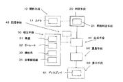
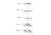
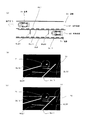
以下、本発明の第1実施形態について、図面を参照して説明する。図1は本実施形態に係る車両周辺の運転支援装置の全体構成のブロック図であり、図2は運転支援装置の作動を表すフローチャートであり、図3と図4は運転支援装置が作動する状況の一例を表すものであり、図3は後方が暗く仕切線が視認できない場合、図4は隣接する車線の後続車が自車に近接しハレーションによって仕切線が視認できない場合を示している。
[First Embodiment]
Hereinafter, a first embodiment of the present invention will be described with reference to the drawings. FIG. 1 is a block diagram of the overall configuration of a driving support device around a vehicle according to the present embodiment, FIG. 2 is a flowchart showing the operation of the driving support device, and FIGS. 3 and 4 are situations in which the driving support device operates. FIG. 3 shows a case where the rear line is dark and the partition line cannot be visually recognized, and FIG. 4 shows a case where the succeeding vehicle of the adjacent lane is close to the own vehicle and the partition line cannot be visually recognized due to halation.
本実施形態に係る運転支援装置は、図1に示すように、自車の後方もしくは後側方の画像を撮影する撮影手段10と、撮影された画像に基づき、道路の状態を判定する判定手段20と、自車の走行状態を検出する検出手段30と、自車が複数の車線を有する道路を走行しているとき、走行状態に基づいてガイド線を生成する生成手段40と、ガイド線が画像に重畳して表示される重畳画像を生成する重畳手段50と、重畳画像を表示する表示手段60とから構成される。 As shown in FIG. 1, the driving support apparatus according to the present embodiment includes an imaging unit 10 that captures an image of the rear or rear side of the vehicle, and a determination unit that determines a road state based on the captured image. 20, a detecting means 30 for detecting the traveling state of the host vehicle, a generating unit 40 for generating a guide line based on the traveling state when the host vehicle is traveling on a road having a plurality of lanes, and a guide line The image forming apparatus includes a superimposing unit 50 that generates a superimposed image displayed on the image and a display unit 60 that displays the superimposed image.
以下、図1と図2、必要に応じて図3と4を参照して全体構成とその作用を詳述する。 Hereinafter, the overall configuration and its operation will be described in detail with reference to FIGS. 1 and 2 and, if necessary, to FIGS. 3 and 4.
撮影手段10は、自車の車体(図示せず)に適切に配設されたカメラ11等によって、自車の後方や側方の状況を撮像する(図2:ステップS101)。 The photographing means 10 captures the situation of the rear and side of the own vehicle with the camera 11 or the like appropriately disposed on the body (not shown) of the own vehicle (FIG. 2: Step S101).
撮影手段10によって撮像された画像は、判定手段20に送られる。判定手段20は、撮像された画像において車線を仕切る仕切線が識別できない理由を判定する(図2:ステップS102)。この判定基準は、カメラの能力(レンズの明るさ等)、画像処理等を考慮して適宜設定することができ、また最終的に運転者が判定基準を微調整することも可能である。 The image captured by the imaging unit 10 is sent to the determination unit 20. The determination unit 20 determines the reason why the partition line that divides the lane in the captured image cannot be identified (FIG. 2: step S102). This determination criterion can be appropriately set in consideration of the camera capability (lens brightness, etc.), image processing, and the like, and the driver can finally finely adjust the determination criterion.
ここで仕切線とは、複数の車線は、道路上に描かれた、自動車の走行方向に沿った白線、白の破線や黄線などによって、仕切られており、本明細書ではこれらの線を仕切線と定義している。また、車線には路側帯も含むものとしている。例えば、高速道路などで緊急車両が路側帯を通過する場合もあるからである。また、後記するように通常の判定手段20に加えて、明暗を詳細に判定する明暗判定手段21や、道路情報等を記憶する記憶手段42を備えてもよい。 Here, the partition lines are a plurality of lanes that are separated by white lines, white broken lines, yellow lines, and the like drawn on the road along the traveling direction of the automobile. It is defined as a dividing line. The lane includes a roadside belt. This is because, for example, an emergency vehicle may pass through a roadside belt on a highway. Further, as will be described later, in addition to the normal determination means 20, a light / dark determination means 21 for determining light and dark in detail and a storage means 42 for storing road information and the like may be provided.
仕切線が判別できない状態の例をいくつか説明する。 Some examples of states in which the partition lines cannot be identified will be described.
仕切線は、道路上に描かれたものであり、路面上の汚れや水溜まりの影響で見え難くなったり、豪雪地方の滑り止めが多用される道路では、削られて消えてしまうときがある。 The dividing line is drawn on the road, and it may be difficult to see due to the dirt on the road surface or a pool of water, or it may be cut off and disappear on a road where heavy slip is used in the heavy snow region.
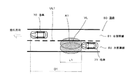
また、照明設備が無い、もしくは、照明設備があっても明るさが足りない夜間の道路は、仕切線が見え難い場合がある。図3は、このような状況において、後方から他車71が走行している例である。
In addition, there are cases where it is difficult to see the dividing line on a road at night when there is no lighting equipment or there is insufficient lighting even if there is lighting equipment. FIG. 3 is an example in which the
自車70は、片側2車線ある道路80の右側車線81(図3では、上側の車線)を、矢印方向に走行している。他車71は、自車の走行車線である右側車線81の隣車線である左側車線82を自車と同方向に走行している。自車70の先頭から他車71の先頭までの距離D1が、他車71の照明範囲A1の前方方向(図の左方向)の距離L1と比べ、十分に大きいものであるとき、仕切線UL1は道路80の照明が不足しているため視認が困難である部分を示しており、仕切線VLは見えないことはないが、前記したように路面上の汚れ等によって見え難くなる部分を示している。また、距離D1が大きくなればなるほど、仕切線VLの判別は困難となる。
The
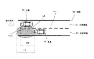
その他には、図4に示すように、自車70の先頭から他車71の先頭までの距離D2が、他車71の照明範囲A2の前方方向(図の左方向)の距離L2と比べ、差が無く、例えば、照明範囲A2内に自車70の一部が含まれるような場合が想定される。このとき、仕切線UL1は道路80の照明が不足していることなどから視認が困難であり、仕切線UL2は他車71のヘッドライト(図示せず)によってカメラ11の撮像がハレーションを生じ判別できない場合がある。
In addition, as shown in FIG. 4, the distance D2 from the head of the
判定手段20が、前記のような道路状態や走行状態を判定した(ステップS102)後、「ガイド線の生成」(ステップS103)に進む。 After the determination unit 20 determines the road state and the traveling state as described above (step S102), the process proceeds to “guide line generation” (step S103).
次に、生成手段40は、検出手段30が検出した車速31、ヨーレート32、操舵角33、自車線認識34等のデータを取り込む。なお、取り込むデータは、前記したものに限定されない。ここで、車速31、ヨーレート32および操舵角33は、自車の走行に係る物理量であり、数値化されて取り込まれる。生成手段40は、例えば、カーナビ制御ユニットに該当する。 Next, the generation unit 40 captures data such as the vehicle speed 31, the yaw rate 32, the steering angle 33, and the own lane recognition 34 detected by the detection unit 30. Note that the data to be captured is not limited to the above-described data. Here, the vehicle speed 31, the yaw rate 32, and the steering angle 33 are physical quantities related to the traveling of the host vehicle, and are numerically captured. The generation means 40 corresponds to, for example, a car navigation control unit.
前記した自車の走行に係る物理量である車速31、ヨーレート32および操舵角33を用いることによって、自車の走行軌跡の時間的変化を算定し、この結果から走行状態に基づく道路形状の推定演算を行うことができる。また、LKAS(レーンキープアシスト)、LDW(レーンデバーチャワーニング)等を装備し、自車線を認識することができる車両の場合には、自車線の自車線認識を行った結果である自車線認識34も取り込むデータとして含まれ、道路形状の推定演算をする上で使用される。 By using the vehicle speed 31, the yaw rate 32, and the steering angle 33, which are physical quantities related to the traveling of the vehicle, the temporal change of the traveling locus of the vehicle is calculated, and the road shape estimation calculation based on the traveling state is calculated from the result. It can be performed. In the case of a vehicle equipped with LKAS (lane keep assist), LDW (lane departure warning), etc. and capable of recognizing the own lane, the own lane recognition that is the result of the own lane recognition is performed. 34 is also included as data to be taken in, and is used for estimating the road shape.
生成手段40は、道路形状の推定演算の結果を基に、ガイド線を生成する(ステップ103)。図5と図6は、生成されたガイド線の例を表すものであり、図5はほぼ直線の道路の場合、図6はカーブした道路の場合の例である。 The generation means 40 generates a guide line based on the result of the road shape estimation calculation (step 103). 5 and 6 show examples of generated guide lines. FIG. 5 shows an example of a substantially straight road, and FIG. 6 shows an example of a curved road.
ガイド線は、道路の軌跡等の道路形状の演算結果から生成されるものであり、その種類、形態は特に限定されないが、例えば、図5もしくは図6に示すように視認が困難な仕切線UL1に倣った仮想仕切線GL11や、この仮想仕切線GL1に直交する方向に引かれた仮想横断線GL21,GL22が好ましい。また、図5(a)の俯瞰した平面図に示すように左側車線82のさらに左側の視認が困難な第2仕切線UL2に倣った第2仮想仕切線GL12も引くこともできる。 The guide line is generated from a calculation result of a road shape such as a road locus, and the type and form thereof are not particularly limited. For example, as shown in FIG. 5 or FIG. The virtual partition line GL11 following the above and the virtual transverse lines GL21 and GL22 drawn in the direction orthogonal to the virtual partition line GL1 are preferable. Further, as shown in the plan view seen from above in FIG. 5A, it is also possible to draw a second virtual partition line GL12 that follows the second partition line UL2 that is difficult to visually recognize on the left side of the left lane 82.
一部前記した説明と重複するが、図6(a)の俯瞰した平面図に示すようにカーブした道路80においても、自車70の走行に係る物理量である車速31、ヨーレート32および操舵角33を用いることによって、自車の走行軌跡の時間的変化を算定し、この結果から走行状態に基づく道路形状の推定演算を行うことができることは言うまでもない。
Although partially overlapping with the above description, the vehicle speed 31, the yaw rate 32, and the steering angle 33, which are physical quantities related to the traveling of the
仮想横断線GL21,GL22は、それぞれを自車70から所定の距離だけ離れて表示されるように設定することにより、運転者は、自車70と、自車が走行している右側車線81と隣接する左側車線82を走行する他車71と、の大凡の距離を視覚によって掴むことができる。
By setting each of the virtual crossing lines GL21 and GL22 to be displayed at a predetermined distance from the
次に生成されたガイド線GL11,GL12,GL21,GL22は、撮影手段10によって撮像された後方画像(ステップ101)に重畳される(ステップ104)。 Next, the generated guide lines GL11, GL12, GL21, GL22 are superimposed on the rear image (step 101) imaged by the imaging means 10 (step 104).
重畳された画像は、表示手段60のディスプレイ61に表示される。 The superimposed image is displayed on the display 61 of the display means 60.
図5(a)で説明した直線路における重畳された画像の一例を図5(b)と図5(c)に示す。図5(b)は、例えば、自車70が、夜間、照明設備の無い図5(a)に示すような片側複数車線を有する直線の道路を走行しているときの重畳画像12である。図5(b)に示すように、撮影手段10によって撮像された後方画像からでは他車71の存在のみが判別できる程度の暗さであり、仕切線UL1、第2仕切線UL2の識別は困難である。かかる状況であっても、生成されたガイド線GL11,GL12,GL21,GL22は、ディスプレイに明瞭に表示される。図5(c)は、図5(b)の重畳画像12に地平線に相当する線分14をさらに重畳した変形例である。かかるガイド線の重畳は、後方を走行する他車71が、どの車線を走行しているのか運転者が判断をする上で、有効な表示となる。さらに、図5(c)のように、線分14を重畳させることによって、運転者がドアミラー等で視認する写像により近くなり、視覚支援をする上で好ましい形態となる。
An example of the superimposed image on the straight road described with reference to FIG. 5A is shown in FIG. 5B and FIG. FIG. 5B is a superimposed image 12 when the
次に、図6(a)で説明したカーブした道路における重畳された画像の一例を図6(b)に示す。図6(b)は、前記した図5(b)と同様に、自車70が、夜間、照明設備の無い片側複数車線を有する道路を走行しているときの重畳画像12である。このように、仕切線UL1、第2仕切線UL2の識別は困難であっても、走行状態に基づく道路形状の推定演算を行って生成されたガイド線GL11,GL12,GL21,GL22は、明瞭に表示される。この実施例のようにカーブしている道路は、前記した直線路と比べ運転者が道路の軌跡を把握することがより困難であり、運転者にとって有用な視覚支援をすることができる。
Next, an example of the superimposed image on the curved road described in FIG. 6A is shown in FIG. FIG. 6B is a superimposed image 12 when the
なお、この際、前記した仮想横断線GL21,GL22は、自車70と他車71との車間距離の段階的な指標に相当するため、運転者が識別しやすいように線の色彩を変えることが好ましい。また、仮想仕切線GL11は、単色の線でも問題ないが、白線、白の破線、黄線等の情報が事前に得られている場合は、実際の道路80の状況に合った色彩とすることが好ましい。
At this time, the virtual crossing lines GL21 and GL22 described above correspond to stepwise indicators of the inter-vehicle distance between the
さらに、判定手段20に明暗判定手段21を備えて、画像の輝度分布から、隣車線と自車線の境界である白線や黄色線を撮像できない理由を判定し、暗すぎて撮像できない場合は、白もしくは、暖色系の色で、ガイド指標を表示し、明るすぎて撮像できない場合は、黒もしくは、寒色系の色で、ガイド線を表示してもよい。 Furthermore, the determination means 20 includes a light / dark determination means 21 to determine from the luminance distribution of the image the reason why the white line or the yellow line that is the boundary between the adjacent lane and the own lane cannot be imaged. Alternatively, the guide index may be displayed in a warm color, and if the image is too bright to capture an image, the guide line may be displayed in black or a cold color.
なお、前記したように、車線には路側帯も含むものとしている。例えば、高速道路などで緊急車両が路側帯を通過する場合もあり、このようなときに自車が幅寄せすることを防止するためである。 As described above, the lane includes the roadside belt. For example, there is a case where an emergency vehicle passes through a roadside belt on a highway or the like.
本実施形態において、道路情報が記憶されているカーナビ等の記憶手段42を付加することにより、自車が走行している道路が複数の車線を有するか否かを容易に判断することができ、必要な道路状況の場合のみ運転支援装置を作動させることもできる。しかし、片側1車線であっても、路側帯を有する自動車専用道路などでは、運転支援装置を作動させる方が好ましい。自車を幅寄せする場合は、後方から自動二輪車や自転車が走行してくるときがあるからである。 In this embodiment, by adding storage means 42 such as car navigation in which road information is stored, it can be easily determined whether the road on which the vehicle is traveling has a plurality of lanes, It is also possible to operate the driving support device only in the necessary road conditions. However, even if it is one lane on one side, it is preferable to operate the driving support device on an automobile-only road having a roadside zone. This is because when the own vehicle is brought closer, a motorcycle or a bicycle sometimes travels from behind.
[第2実施形態]
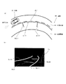
次に、本発明の第2実施形態について図面を参照して説明する。なお、第1実施形態と重複する部分については省略し、差異のある部分を中心に説明する。図7は、本実施形態に係る概念説明図である。
[Second Embodiment]
Next, a second embodiment of the present invention will be described with reference to the drawings. Note that portions that are the same as those in the first embodiment will be omitted, and the differences will be mainly described. FIG. 7 is a conceptual explanatory diagram according to the present embodiment.
本実施形態は、走行状態に基づく道路形状の推定演算の手法が一部異なるものであり、基本的な構成は、第1実施形態と同じである。 The present embodiment is partly different from the road shape estimation calculation method based on the running state, and the basic configuration is the same as that of the first embodiment.
車両が走行する道路80は、図5もしくは図6に示したような直線や単調なカーブだけではなく、図7(a)に示すようなS字に近いカーブや、途中で曲率が変化するカーブなど様々な軌跡を有している。なお、図7(a)においては、片側3車線の道路の中央車線83を自車70が走行している状況を示している。
The road 80 on which the vehicle travels is not only a straight line or a monotonous curve as shown in FIG. 5 or FIG. 6, but also a curve close to an S-shape as shown in FIG. It has various trajectories. FIG. 7A shows a situation in which the
このような道路80の軌跡は、現在の自車70Nの位置の走行状態(車速、ヨーレートおよび操舵角等。前記した説明を参照)のデータだけでは、正確に算定することは困難である。すなわち、過去の自車70Pの位置の走行状態とは、車速、ヨーレート、操舵角等が異なることが推測される。
Such a trajectory of the road 80 is difficult to calculate accurately only with the data of the traveling state (vehicle speed, yaw rate, steering angle, etc., see the above description) at the current position of the
本実施形態は、このような道路80の実態を加味したものであり、過去の自車70Pの位置の走行状態(走行に係る物理量)を取り込むことにより、より正確な道路80の軌跡を算定することができる。ここで、過去の自車70Pは、図7では1点のみ表しているが、複数点の走行状態を取り込むことによって、より正確な軌跡を算定できる。しかしながら、算定結果を反映させたガイド線は、最終的に視認可能な自車の後方の画像に重畳されることから、あまり多くの点での走行状態を取り込む必要はない。
In the present embodiment, the actual condition of the road 80 is taken into account, and a more accurate trajectory of the road 80 is calculated by taking in the past traveling state (physical quantity related to traveling) of the position of the
本実施形態における過去の自車70Pと現在の自車70Nの重畳画像12P,12Nの一例を図7(b)と図7(c)に示す。図7(b)において、過去の自車70Pは、前記した図6(b)と同様な単調なカーブを走行しているものとしている。単調なカーブとして、現在の自車70Nの重畳画像12を作成すると、図6(b)と同様な重畳画像となる。しかしながら、本実施形態は、過去の自車70Pでの走行状態を取り込み、正確な道路80の軌跡を算定しているため、図7(c)に示すような実際の道路状況を忠実に再現した重畳画像12Nを提供することができる。図7(c)の重畳画像12Nには、仕切線GL11と第2仕切線GL12が元の画像に重畳されており、運転者は道路の軌跡を容易に把握できる。
An example of the superimposed images 12P and 12N of the past
以上、本発明について好適な実施形態を説明した。本発明は、図面に記載したものに限定されることなく、その趣旨を逸脱しない範囲で設計変更が可能である。例えば、前記した第1実施形態において後方を走行する他車の位置をミリ波レーダ等によって検出し、この他車の位置をさらに重畳させることもできる。係る構成によって、霧や豪雨などで視界が極めて不良な事態に遭遇した場合であっても、運転者は、後方の他車は自車と同じ車線を走行しているのか、隣車線を走行しているのか、自車と他車との距離はどの程度か、等の情報を、表示手段を通じて取得することができる。 The preferred embodiments of the present invention have been described above. The present invention is not limited to the one described in the drawings, and design changes can be made without departing from the spirit of the present invention. For example, in the first embodiment described above, the position of another vehicle traveling behind can be detected by a millimeter wave radar or the like, and the position of this other vehicle can be further superimposed. With such a configuration, even when a situation where visibility is extremely poor due to fog, heavy rain, etc., the driver must drive in the adjacent lane, whether the other vehicle behind is traveling in the same lane as his / her own vehicle. It is possible to obtain information such as the distance between the vehicle and the other vehicle through the display means.
10 撮影手段
11 カメラ
12 重畳画像
20 判定手段
30 検出手段
31 車速
32 ヨーレート
33 操舵角
34 白車線認識
40 生成手段
41 明暗判定手段
42 記憶手段
50 重畳手段
51 重畳画像
60 表示手段
61 ディスプレイ
70 自車
71 他車
80 道路
81 右側車線
82 左側車線
GL ガイド線
DESCRIPTION OF SYMBOLS 10 Image | photographing means 11 Camera 12 Superimposed image 20 Determination means 30 Detection means 31 Vehicle speed 32 Yaw rate 33 Steering angle 34 White lane recognition 40 Generation means 41 Light / darkness determination means 42 Storage means 50 Superimposition means 51 Superimposed image 60 Display means 61
Claims (8)
自車の後側方の画像を撮影する撮影手段と、
前記画像に基づき、道路の状態を判定する判定手段と、
自車の走行状態を検出する検出手段と、
前記自車が複数の車線を有する道路を走行するとき、前記走行状態に基づいて前記複数の車線を識別するガイド線を生成する生成手段と、
前記ガイド線が前記画像に重畳して表示される重畳画像を生成する重畳手段と、
前記重畳画像を表示する表示手段と、を備え、
前記ガイド線は、少なくとも地平線に相当する線分と、前記複数の車線を仕切る仕切線を仮想的に表した仮想仕切線とを含み、
前記仮想仕切線は、前記自車が走行する自車線に隣接する隣車線における路側帯を含む、
車両の運転支援装置。 A driving support device that displays an image of the periphery of the vehicle in a visible manner to the driver,
Photographing means for photographing an image of the rear side of the vehicle;
Determination means for determining the state of the road based on the image;
Detection means for detecting the traveling state of the vehicle;
Generating means for generating guide lines for identifying the plurality of lanes based on the traveling state when the vehicle travels on a road having a plurality of lanes;
Superimposing means for generating a superimposed image in which the guide line is displayed superimposed on the image;
Display means for displaying the superimposed image,
The guide wire may include at least a line segment corresponding to the horizon, and a virtual partition line of partition lines representing virtually partitioning the plurality of lanes,
The virtual partition line includes a roadside zone in an adjacent lane adjacent to the own lane on which the host vehicle travels.
Vehicle driving support device.
前記ガイド線の明暗および/または色彩は、前記画像の輝度によって前記明暗判定手段が決定する請求項2に記載の車両の運転支援装置。 Further comprising light / dark determination means for determining light and dark and / or color around the vehicle according to the brightness of the image;
The driving assistance apparatus for a vehicle according to claim 2, wherein the brightness and / or darkness and / or color of the guide line is determined by the brightness / darkness determining means according to the brightness of the image.
前記生成手段は、前記記憶手段に蓄積された現在の前記走行状態または/および過去の前記走行状態に基づき、ガイド線を生成する請求項1ないし請求項4のいずれか一項に記載の車両の運転支援装置。 It further has storage means for accumulating the running state detected by the detection means,
The generation unit, based on the current running state of the stored in the storage means running condition and / or past, according to any one of claims 1 to 4 to generate a guide line of the vehicle Driving assistance device.
前記道路情報は、自車が走行している道路の車線数の情報を含む請求項1ないし請求項5のいずれか一項に記載の車両の運転支援装置。 The storage means stores road information,
The vehicle driving support device according to any one of claims 1 to 5 , wherein the road information includes information on a number of lanes of a road on which the vehicle is traveling.
前記他車検出手段は、他車の位置を検出し、
前記ガイド線に対する前記他車の位置が、前記重畳画像にさらに重畳して表示される請求項1ないし請求項6のいずれか一項に記載の運転支援装置。 Other vehicle detection means for detecting the other vehicle running state of the other vehicle traveling behind or behind the host vehicle,
The other vehicle detection means detects the position of the other vehicle,
The driving assistance device according to any one of claims 1 to 6 , wherein a position of the other vehicle with respect to the guide line is further superimposed on the superimposed image.
請求項3に記載の車両の運転支援装置。 The guide line is displayed using a different color between a portion where the brightness of the image is higher than a predetermined brightness and a portion whose background is a low area.
The vehicle driving support device according to claim 3.
Priority Applications (1)
| Application Number | Priority Date | Filing Date | Title |
|---|---|---|---|
| JP2008173919A JP5259277B2 (en) | 2008-07-02 | 2008-07-02 | Driving assistance device |
Applications Claiming Priority (1)
| Application Number | Priority Date | Filing Date | Title |
|---|---|---|---|
| JP2008173919A JP5259277B2 (en) | 2008-07-02 | 2008-07-02 | Driving assistance device |
Publications (2)
| Publication Number | Publication Date |
|---|---|
| JP2010012904A JP2010012904A (en) | 2010-01-21 |
| JP5259277B2 true JP5259277B2 (en) | 2013-08-07 |
Family
ID=41699444
Family Applications (1)
| Application Number | Title | Priority Date | Filing Date |
|---|---|---|---|
| JP2008173919A Expired - Fee Related JP5259277B2 (en) | 2008-07-02 | 2008-07-02 | Driving assistance device |
Country Status (1)
| Country | Link |
|---|---|
| JP (1) | JP5259277B2 (en) |
Cited By (2)
| Publication number | Priority date | Publication date | Assignee | Title |
|---|---|---|---|---|
| CN109479122A (en) * | 2016-07-28 | 2019-03-15 | 卡森尼可关精株式会社 | Vehicle periphery monitoring device and vehicle periphery monitoring method |
| CN111656775A (en) * | 2018-01-25 | 2020-09-11 | 歌乐株式会社 | Display control device and display system |
Families Citing this family (5)
| Publication number | Priority date | Publication date | Assignee | Title |
|---|---|---|---|---|
| WO2012172842A1 (en) * | 2011-06-13 | 2012-12-20 | 本田技研工業株式会社 | Driving assistance device |
| EP2851864B1 (en) * | 2012-05-18 | 2016-09-07 | Nissan Motor Co., Ltd. | Vehicular display apparatus, vehicular display method, and vehicular display program |
| JP7128585B2 (en) * | 2018-11-15 | 2022-08-31 | アルパイン株式会社 | electronic mirror system |
| JP7140058B2 (en) * | 2019-06-27 | 2022-09-21 | トヨタ自動車株式会社 | Vehicle rear side monitoring device |
| JP7056632B2 (en) * | 2019-09-05 | 2022-04-19 | トヨタ自動車株式会社 | Driving support device |
Family Cites Families (11)
| Publication number | Priority date | Publication date | Assignee | Title |
|---|---|---|---|---|
| JPH0211438A (en) * | 1988-06-27 | 1990-01-16 | Clarion Co Ltd | Device for reading information outside vehicle |
| JP3184656B2 (en) * | 1993-03-04 | 2001-07-09 | シャープ株式会社 | In-vehicle surveillance camera device |
| JP4723703B2 (en) * | 1999-06-25 | 2011-07-13 | 富士通テン株式会社 | Vehicle driving support device |
| JP3802723B2 (en) * | 2000-01-11 | 2006-07-26 | 日産ディーゼル工業株式会社 | Vehicle front situation display device |
| JP2001357497A (en) * | 2000-06-13 | 2001-12-26 | Mitsubishi Motors Corp | Rear side vehicle monitoring device |
| JP2002104117A (en) * | 2000-10-03 | 2002-04-10 | Denso Corp | Driving support system for vehicle |
| JP2002362270A (en) * | 2001-06-11 | 2002-12-18 | Matsushita Electric Ind Co Ltd | Driving support device |
| JP2006051850A (en) * | 2004-08-10 | 2006-02-23 | Matsushita Electric Ind Co Ltd | Drive assisting device and drive assisting method |
| JP4882285B2 (en) * | 2005-06-15 | 2012-02-22 | 株式会社デンソー | Vehicle travel support device |
| JP4644550B2 (en) * | 2005-07-20 | 2011-03-02 | 株式会社オートネットワーク技術研究所 | Camera system |
| JP2007241470A (en) * | 2006-03-06 | 2007-09-20 | Toyota Motor Corp | Device for updating map data for vehicle |
-
2008
- 2008-07-02 JP JP2008173919A patent/JP5259277B2/en not_active Expired - Fee Related
Cited By (3)
| Publication number | Priority date | Publication date | Assignee | Title |
|---|---|---|---|---|
| CN109479122A (en) * | 2016-07-28 | 2019-03-15 | 卡森尼可关精株式会社 | Vehicle periphery monitoring device and vehicle periphery monitoring method |
| CN111656775A (en) * | 2018-01-25 | 2020-09-11 | 歌乐株式会社 | Display control device and display system |
| CN111656775B (en) * | 2018-01-25 | 2022-04-29 | 歌乐株式会社 | Display control device and display system |
Also Published As
| Publication number | Publication date |
|---|---|
| JP2010012904A (en) | 2010-01-21 |
Similar Documents
| Publication | Publication Date | Title |
|---|---|---|
| JP7416176B2 (en) | display device | |
| JP6354776B2 (en) | Vehicle control device | |
| JP6259482B2 (en) | Display control device for vehicle | |
| JP6272375B2 (en) | Display control device for vehicle | |
| US20200324787A1 (en) | Augmented reality method and apparatus for driving assistance | |
| WO2020125178A1 (en) | Vehicle driving prompting method and apparatus | |
| JP5259277B2 (en) | Driving assistance device | |
| US20130179023A1 (en) | Methods for informing a motor vehicle driver of a driving maneuver, a driver assistance system for a motor vehicle that utilizes the method, and a motor vehicle having the driver assistance system | |
| JP6460019B2 (en) | Vehicle control device | |
| CN107650639B (en) | Visual field control device | |
| US20170043720A1 (en) | Camera system for displaying an area exterior to a vehicle | |
| JP2008030729A (en) | Vehicular display device | |
| US11601621B2 (en) | Vehicular display system | |
| CN112747765A (en) | Path pushing method and system based on navigation and sensor fusion and storage medium | |
| CN114987460A (en) | Method and apparatus for blind spot assist of vehicle | |
| JP2024029051A (en) | In-vehicle display device, method and program | |
| JP2004310522A (en) | Vehicular image processor | |
| JP6625480B2 (en) | Display system | |
| JP6398182B2 (en) | Signal information presentation device | |
| US8681219B2 (en) | System and method for driving assistance at road intersections | |
| JP3363935B2 (en) | Vehicle display device | |
| CN109987025B (en) | Vehicle driving assistance system and method for night environment | |
| CN113448097B (en) | Display device for vehicle | |
| JPH06255397A (en) | Display device for vehicle | |
| JP6380480B2 (en) | Visibility control device |
Legal Events
| Date | Code | Title | Description |
|---|---|---|---|
| A621 | Written request for application examination |
Free format text: JAPANESE INTERMEDIATE CODE: A621 Effective date: 20101125 |
|
| A977 | Report on retrieval |
Free format text: JAPANESE INTERMEDIATE CODE: A971007 Effective date: 20120719 |
|
| A131 | Notification of reasons for refusal |
Free format text: JAPANESE INTERMEDIATE CODE: A131 Effective date: 20120828 |
|
| A521 | Request for written amendment filed |
Free format text: JAPANESE INTERMEDIATE CODE: A523 Effective date: 20121023 |
|
| A131 | Notification of reasons for refusal |
Free format text: JAPANESE INTERMEDIATE CODE: A131 Effective date: 20121218 |
|
| A521 | Request for written amendment filed |
Free format text: JAPANESE INTERMEDIATE CODE: A523 Effective date: 20130208 |
|
| TRDD | Decision of grant or rejection written | ||
| A01 | Written decision to grant a patent or to grant a registration (utility model) |
Free format text: JAPANESE INTERMEDIATE CODE: A01 Effective date: 20130416 |
|
| A61 | First payment of annual fees (during grant procedure) |
Free format text: JAPANESE INTERMEDIATE CODE: A61 Effective date: 20130424 |
|
| FPAY | Renewal fee payment (event date is renewal date of database) |
Free format text: PAYMENT UNTIL: 20160502 Year of fee payment: 3 |
|
| R150 | Certificate of patent or registration of utility model |
Free format text: JAPANESE INTERMEDIATE CODE: R150 |
|
| LAPS | Cancellation because of no payment of annual fees |