JP5188260B2 - Image processing apparatus, image processing method, program thereof, and storage medium - Google Patents
Image processing apparatus, image processing method, program thereof, and storage medium Download PDFInfo
- Publication number
- JP5188260B2 JP5188260B2 JP2008122561A JP2008122561A JP5188260B2 JP 5188260 B2 JP5188260 B2 JP 5188260B2 JP 2008122561 A JP2008122561 A JP 2008122561A JP 2008122561 A JP2008122561 A JP 2008122561A JP 5188260 B2 JP5188260 B2 JP 5188260B2
- Authority
- JP
- Japan
- Prior art keywords
- metadata
- attribute
- image processing
- giving
- dividing
- Prior art date
- Legal status (The legal status is an assumption and is not a legal conclusion. Google has not performed a legal analysis and makes no representation as to the accuracy of the status listed.)
- Expired - Fee Related
Links
Images


Classifications
-
- G—PHYSICS
- G06—COMPUTING; CALCULATING OR COUNTING
- G06F—ELECTRIC DIGITAL DATA PROCESSING
- G06F40/00—Handling natural language data
- G06F40/10—Text processing
- G06F40/166—Editing, e.g. inserting or deleting
- G06F40/169—Annotation, e.g. comment data or footnotes
-
- Y—GENERAL TAGGING OF NEW TECHNOLOGICAL DEVELOPMENTS; GENERAL TAGGING OF CROSS-SECTIONAL TECHNOLOGIES SPANNING OVER SEVERAL SECTIONS OF THE IPC; TECHNICAL SUBJECTS COVERED BY FORMER USPC CROSS-REFERENCE ART COLLECTIONS [XRACs] AND DIGESTS
- Y10—TECHNICAL SUBJECTS COVERED BY FORMER USPC
- Y10S—TECHNICAL SUBJECTS COVERED BY FORMER USPC CROSS-REFERENCE ART COLLECTIONS [XRACs] AND DIGESTS
- Y10S707/00—Data processing: database and file management or data structures
- Y10S707/912—Applications of a database
- Y10S707/913—Multimedia
Landscapes
- Engineering & Computer Science (AREA)
- Theoretical Computer Science (AREA)
- Health & Medical Sciences (AREA)
- Artificial Intelligence (AREA)
- Audiology, Speech & Language Pathology (AREA)
- Computational Linguistics (AREA)
- General Health & Medical Sciences (AREA)
- Physics & Mathematics (AREA)
- General Engineering & Computer Science (AREA)
- General Physics & Mathematics (AREA)
- Processing Or Creating Images (AREA)
Description
本発明は、例えば、複合複写装置等の画像処理装置、画像処理方法ならびにそのプログラムおよび記憶媒体に関する。 The present invention relates to an image processing apparatus such as a composite copying apparatus, an image processing method, a program thereof, and a storage medium.
近年、環境問題が叫ばれる中、オフィスでのペーパーレス化が急速に進んでいる。このペーパーレス化を実現する従来技術として、次のような文書管理システムや画像通信システムなどを挙げることができる。文書管理システムでは、まず、バインダー等で蓄積された紙文書をスキャナで読み取る。その読み取った画像を、例えば、Portable Document Format(以下、PDF)に変換して、画像記憶装置に蓄積して管理することが行われる。画像通信システムでは、PDF等に変換したデータを遠隔地に送信することが行われる(特許文献1)。 In recent years, paperless offices are rapidly becoming paperless as environmental problems are screamed. The following document management system and image communication system can be cited as conventional techniques for realizing this paperless. In the document management system, first, a paper document accumulated by a binder or the like is read by a scanner. The read image is converted into, for example, a Portable Document Format (hereinafter referred to as PDF), stored in an image storage device, and managed. In the image communication system, data converted into PDF or the like is transmitted to a remote place (Patent Document 1).
一方、電子化された情報として保存した文書を有効に活用するために、保存した大量の情報の中から必要な情報を検索する技術が重要となってきている。例えば、図,表,写真等の画像および文字列が混在した文書中の画像を検索するための方法が提案されている(特許文献2)。特許文献2に開示の技術では、文書中の画像およびその画像について記述した文字列を抽出し、かつ、それらを関連づけて格納している。そして、検索の際には、ユーザーにより指定された任意の検索語に基づいて、格納済みの文字列を検索して、該当する文字列に関連づけられた画像を出力することができるものとなっている。
On the other hand, in order to effectively use documents stored as digitized information, a technique for retrieving necessary information from a large amount of stored information has become important. For example, a method for searching for an image in a document in which images such as figures, tables, and photographs and character strings are mixed has been proposed (Patent Document 2). In the technique disclosed in
さらに、画像に対する注釈情報の付与を容易に行なう方法が提案されている(特許文献3)。これは、画像(例えば、人物画像)と、各々がメタデータ(例えば、人名のメタデータ)と関連している複数のアイコンとを表示し、画像にアイコンをドラッグ&ドロップすることで、画像に対してアイコンと関連するメタデータを注釈としてつける方法である。 Furthermore, a method for easily giving annotation information to an image has been proposed (Patent Document 3). This is done by displaying an image (eg, a person image) and a plurality of icons each associated with metadata (eg, person name metadata) and dragging and dropping the icon onto the image. On the other hand, it is a method of annotating metadata associated with icons.
しかしながら、特許文献2に示されるように、文書中の文字列を検索のためのメタデータとして画像に付与する方法では、適切なメタデータがつかない場合がある。さらには、適切なメタデータがついていたとしても、追加、削除など、メタデータの編集を行いたい場合がある。
However, as shown in
このような時、ユーザーは、画像とメタデータが表示されているメタデータ編集画面を見ながら、キーボード入力より、所望のメタデータに編集することが一般的であるが、編集しようとするメタデータの数が多いと、ユーザーの負担になるという課題がある。 In such a case, it is common for the user to edit to the desired metadata by keyboard input while looking at the metadata editing screen on which the image and metadata are displayed. There is a problem that it becomes a burden on the user if there are many numbers.
また、特許文献3の、画像にアイコンをドラッグ&ドロップして、この画像に対してアイコンと関連するメタデータを注釈としてつける方法では、注釈のつき方が常に一方向で、固定であるため、ユーザーの操作を制限してしまうという課題があった。
In addition, in the method of
即ち、画像に対してアイコンという画像をドラッグ&ドロップする方法しかないため、逆に、アイコンに対して画像をドラッグ&ドロップして注釈をつけることはできなかった。 That is, since there is only a method of dragging and dropping an image called an icon on the image, it is not possible to add an annotation by dragging and dropping the image on the icon.
また、別の課題として、写真画像に対して文字画像を、文字画像に対して写真画像を、文字画像に対して文字画像をドラッグ&ドロップして注釈をつけることもできなかった。
さらに、この方法では、写真画像に対して写真画像、写真画像に対して文字画像、文字画像に対して写真画像、文字画像に対して文字画像をドラッグ&ドロップした時の注釈の付き方を各々変更させることができない。そのため、注釈の付き方がユーザーにとって直感的に理解しづらいという課題があった。
Further, as another problem, it has been impossible to annotate a character image with respect to a photographic image, a photographic image with respect to the character image, and a character image with respect to the character image by drag and drop.
Furthermore, in this method, a photographic image with respect to a photographic image, a character image with respect to the photographic image, a photographic image with respect to the character image, and an annotation method when the character image is dragged and dropped with respect to the character image, respectively. It cannot be changed. For this reason, there is a problem that it is difficult for the user to intuitively understand how to add annotations.
上述した課題を解決するために、本発明の画像処理装置は、イメージデータを入力する入力手段と、前記入力手段により入力されたイメージデータを複数のオブジェクトに分割するオブジェクト分割手段と、前記オブジェクト分割手段により得られた各オブジェクトへメタデータを付与するメタデータ付与手段と、メタデータ付与手段により付与されたオブジェクトからメタデータの編集対象となる第1のオブジェクトと第2のオブジェクトとを選択する選択手段と、前記選択手段で選択された前記第1のオブジェクトと第2のオブジェクトそれぞれのメタデータの属性を解析するメタデータ解析手段と、前記第1のオブジェクトの属性または前記第2のオブジェクトの属性のいずれか一方が文字であり、他方が写真、またはグラフィック(図面、線画、表)である場合、属性が文字であるオブジェクトのメタデータを、属性が写真、またはグラフィック(図面、線画、表)であるオブジェクトのメタデータへ追加し、前記第1のオブジェクトの属性および前記第2のオブジェクトの属性が文字である場合、前記第1のオブジェクトと前記第2のオブジェクトのメタデータの文字数の大小比較を行い、該大小比較の結果、少ない文字数を有するオブジェクトに、多い文字数を有するオブジェクトのメタデータを追加し、前記第1のオブジェクトの属性および前記第2のオブジェクトの属性が写真、またはグラフィック(図面、線画、表)である場合、前記第1のオブジェクトのリンク情報を示すアドレスを前記第2のオブジェクトのメタデータへ追加するように前記第1のオブジェクトのメタデータと前記第2のオブジェクトのメタデータの更新手順を決定する決定手段と、前記決定手段により決定した更新手順で前記第1のオブジェクトのメタデータと前記第2のオブジェクトのメタデータとの少なくともいずれかを更新する更新手段とを備えることを特徴とする。 In order to solve the above-described problems, an image processing apparatus according to the present invention includes an input unit that inputs image data, an object dividing unit that divides the image data input by the input unit into a plurality of objects, and the object division. Metadata giving means for giving metadata to each object obtained by the means, and selection for selecting the first object and the second object that are metadata editing targets from the objects given by the metadata giving means Means, metadata analysis means for analyzing metadata attributes of the first object and the second object selected by the selection means, and attributes of the first object or attributes of the second object Is one of the letters and the other is a photo or graphic ( The attribute of the object whose attribute is text is added to the metadata of the object whose attribute is a photograph or graphic (drawing, line drawing, table). When the attribute and the attribute of the second object are characters, the number of characters in the metadata of the first object and the second object is compared, and as a result of the size comparison, an object having a small number of characters is If the metadata of an object having a large number of characters is added and the attribute of the first object and the attribute of the second object are a photograph or a graphic (drawing, line drawing, table), the link of the first object wherein an address indicating the information to add to the metadata of the second object first object Determining means for determining the update procedure of the metadata of the second object and metadata of the second object, and the metadata of the first object and the metadata of the second object in the update procedure determined by the determining means; Update means for updating at least one of the above.
本発明によれば、メタデータの編集が容易であり、ユーザーにとって直感的に理解がしやすく、かつ後で再利用・検索がしやすいメタデータの付与が可能となる。 According to the present invention, it is possible to add metadata that is easy to edit metadata, easy for the user to understand intuitively, and easy to reuse and search later.
例えば、写真画像に対して写真画像のメタデータを付与することができるだけでなく、写真画像に対して文字画像のメタデータを、また文字画像に対して写真画像のメタデータを、また文字画像に対して文字画像のメタデータを付与することが可能である。 For example, not only can photo image metadata be assigned to a photo image, but also text image metadata can be applied to a photo image, photo image metadata can be applied to a character image, and a character image can be converted to a character image. On the other hand, it is possible to give metadata of a character image.
さらに、写真画像に対して写真画像を、写真画像に対して文字画像を、文字画像に対して写真画像を、文字画像に対して文字画像を関連付けした時のメタデータの付き方を各々変更することが可能である。これにより、写真画像に対して、写真画像を関連付けする場合、前者の写真画像に後者の写真画像のリンク先をメタデータとして追加しておき、前者の写真画像を検索した場合、容易に後者の写真画像を辿ることができる。 Further, the method of attaching metadata when the photographic image is associated with the photographic image, the character image with respect to the photographic image, the photographic image with respect to the character image, and the character image with respect to the character image is changed. It is possible. As a result, when a photographic image is associated with a photographic image, the link destination of the latter photographic image is added as metadata to the former photographic image, and when the former photographic image is searched, the latter You can trace photographic images.
さらに、文字画像に対して、文字画像を関連付けする場合、キャプション文字数の少ない方の文字画像に対して、キャプション文字数の多い方の文字画像のメタデータを付与することで、ユーザーが直感的に利用しやすくなる。 In addition, when associating a character image with a character image, the user can intuitively use the character image with the larger number of caption characters by adding metadata of the character image with the larger number of caption characters. It becomes easy to do.
また、写真画像に対して、写真画像を関連付けした場合に、ユーザーに応じて処理を切り替え、同一ユーザーならば前者の写真画像に後者の写真画像のリンク先を付加させ、異なるユーザーならば後者の写真画像を付加させる。これによって、後日、後者の写真画像のメタデータが別のユーザーによって不測のものに書き換えられたとしても、前者の写真画像の検索性を損なわないという利点がある。 In addition, when a photographic image is associated with a photographic image, the process is switched according to the user, and if the same user, the link destination of the latter photographic image is added to the former photographic image. Add a photographic image. As a result, there is an advantage that even if the metadata of the latter photographic image is rewritten unexpectedly by another user at a later date, the searchability of the former photographic image is not impaired.
[実施形態1]
次に本発明に係る画像処理方法の第1の実施形態を図面に基づいて説明する。
[Embodiment 1]
Next, a first embodiment of an image processing method according to the present invention will be described with reference to the drawings.
本実施形態1では、関連付けされた第1と第2のオブジェクトの属性に基づいて、メタデータのマージ方法を切り替える方法について説明する。 In the first embodiment, a method of switching the metadata merging method based on the attributes of the associated first and second objects will be described.
本実施形態で参照する図面は以下のとおりである。 The drawings referred to in this embodiment are as follows.
図1は、本発明を適用できる画像処理システムを示すブロック図であり、図2は、図1におけるMFPを示すブロック図、また図3は本実施形態1で説明する第1のデータ処理フローである。また図7は、ベクトル化処理の中で実施するオブジェクト分割処理で領域分割情報した結果の一例を表し、図8は、オブジェクト分割したときの各属性のブロック情報および入力ファイル情報を表す。図9は、再利用可能なデータへの変換で重要なベクトル化処理のフロー図である。図10は、ベクトル化の処理における角抽出の処理を示す図であり、図11は、ベクトル化の処理における輪郭線まとめの処理を示す図である。図12は、図9で生成されたベクトルデータのグループ化の処理を示すフローチャートであり、図13は、図12の処理でグループ化されたベクトルデータに対する図形要素検出の処理を示すフローチャートである。また図14は、本実施形態1に係るベクトル化処理結果のデータを示すマップであり、図15は、アプリデータ変換の処理を示すフローチャートである。図16は、図15の文書構造ツリー生成の処理を示すフローチャートであり、図17は、文書構造ツリー生成処理の対象となる文書を示す図である。図18は、図16の処理によって生成される文書構造ツリーを示す図であり、図19は、本実施形態1で説明するScalable Vector Graphics(以下、SVG)形式の一例である。 FIG. 1 is a block diagram showing an image processing system to which the present invention can be applied, FIG. 2 is a block diagram showing the MFP in FIG. 1, and FIG. 3 is a first data processing flow described in the first embodiment. is there. FIG. 7 shows an example of the result of area division information obtained by the object division processing executed in the vectorization process, and FIG. 8 shows block information and input file information of each attribute when the object is divided. FIG. 9 is a flow chart of vectorization processing important for conversion to reusable data. FIG. 10 is a diagram showing corner extraction processing in vectorization processing, and FIG. 11 is a diagram showing outline grouping processing in vectorization processing. FIG. 12 is a flowchart showing the grouping process of the vector data generated in FIG. 9, and FIG. 13 is a flowchart showing the graphic element detection process for the vector data grouped in the process of FIG. FIG. 14 is a map showing vectorization processing result data according to the first embodiment, and FIG. 15 is a flowchart showing application data conversion processing. FIG. 16 is a flowchart showing the document structure tree generation processing of FIG. 15, and FIG. 17 is a diagram showing a document to be subjected to the document structure tree generation processing. FIG. 18 is a diagram showing a document structure tree generated by the processing of FIG. 16, and FIG. 19 is an example of a Scalable Vector Graphics (hereinafter referred to as SVG) format described in the first embodiment.
[画像処理システム]
はじめに、本実施形態で使用可能画像処理システムについて図1を用いて説明する。
[Image processing system]
First, an image processing system usable in this embodiment will be described with reference to FIG.
図1において、本実施形態における画像処理システムは、オフィス10とオフィス20とをインターネット104で接続した環境において使用される。 In FIG. 1, the image processing system in the present embodiment is used in an environment in which an office 10 and an office 20 are connected via the Internet 104.
オフィス10内に構築されたLAN107には、記録装置としてのマルチファンクション複合機(以下、MFP)100が接続されている。また、MFP100を制御するマネージメントPC101、ローカルPC102、文書管理サーバ106、文書管理サーバ106のためのデータベース105が接続されている。
A multifunction machine (hereinafter referred to as MFP) 100 as a recording apparatus is connected to a
オフィス20内にはLAN108が構築され、LAN108には文書管理サーバ106、および文書管理サーバ106のためのデータベース105が接続されている。
A
LAN107、108にはプロキシサーバ103が接続され、LAN107、108はプロキシサーバ103を介してインターネットに接続される。
A
MFP100は、原稿から読み取った入力画像に対する画像処理の一部を担当し、処理結果としての画像データはLAN109を通じてマネージメントPC101に入力する機能がある。加えて、ローカルPC102、もしくは不図示の汎用PCから送信されるPage Discription Language(以下、PDL)言語を解釈して、プリンタとして作用する。さらには、原稿から読み取った画像をローカルPC102もしくは、不図示の汎用PCに送信する機能をもつ。マネージメントPC101は、画像記憶手段、画像処理手段、表示手段、入力手段等を含む通常のコンピュータであり、機能的にはこれら構成要素の一部がMFP100と一体化して、画像処理システムの構成要素となっている。なお、本実施形態では、マネージメントPCを介してデータベース105において、下記に記載する登録処理などが実行されるものとするが、マネージメントPCで行われる処理をMFPで実行するようにしても構わない。
The
さらにMFP100は、LAN109によってマネージメントPC101に直接接続されている。
Further, the
[MFP]
図2において、MFP100は、図示しないAuto Document Feeder(以下、ADF)を有する画像読み取り部110を備える。画像読み取り部110は束状の或いは1枚の原稿の画像を光源で照射し、反射画像をレンズで固体撮像素子上に結像する。固体撮像素子は所定解像度(例えば600dpi)および所定輝度レベル(例えば8ビット)の画像読み取り信号を生成し、画像読み取り信号からラスターデータよりなる画像データが構成される。
[MFP]
2, the
MFP100は、記憶装置(以下、BOX)111および記録装置112を有し、通常の複写機能を実行する際には、イメージデータをデータ処理装置115によって、複写用の画像処理をして記録信号に変換する。複数枚複写の場合には、1頁分の記録信号を一旦BOX111に記憶保持した後、記録装置112に順次出力して、記録紙上に記録画像を形成する。
The
MFP100は、LAN107との接続のためのネットワークI/F114を有し、ローカルPC102、もしくは他の汎用PC(不図示)からドライバーを利用して出力するPDL言語によるPDLデータを、記録装置112によって記録し得る。ローカルPC102からドライバーを経由して出力されるPDLデータは、LAN107からネットワークI/F114を経てデータ処理装置115に入力される。その後、PDLの言語を解釈・処理することで記録可能な記録信号に変換された後、MFP100において、記録紙上に記録画像として記録される。
The
BOX111は、画像読み取り部110からのデータやローカルPC102からドライバーを経由して出力されるPDLデータをレンダリングしたデータを保存できる機能を有している。
The
MFP100は、MFP100に設けられたキー操作部(入力装置113)、あるいはマネージメントPC101の入力装置(キーボード、ポインティングデバイス等)を通じて操作される。これらの操作のために、データ処理装置115 は内部の制御部(図示せず。)によって所定の制御を実行する。
The
MFP100は表示装置116を有し、操作入力の状態と、処理すべきイメージデータとを、表示装置116によって表示し得る。
The
BOX111はI/F117を介して、マネージメントPC101から直接制御し得る。LAN109は、MFP100とマネージメントPC101との間のデータの授受、制御信号授受に用いられる。
The
[データ処理装置115の詳細]
次に、図2のデータ処理装置115の詳細について、図41を用いて説明する。
[Details of Data Processing Device 115]
Next, details of the
尚、図41の110〜116については、図2の説明において前述しているため説明を一部省略する。 41 have already been described in the description of FIG. 2, a part of the description is omitted.
データ処理装置115は、CPU、メモリ等で構成される制御ユニットであり、画像情報やデバイス情報の入出力を行うコントローラである。ここで、CPU120はシステム全体を制御するコントローラである。RAM123はCPU120が動作するためのシステムワークメモリであり、画像データを一時記憶するための画像メモリでもある。ROM122はブートROMであり、システムのブートプログラムが格納されている。
The
操作部I/F121は操作部133とのインターフェース部で、操作部133に表示するための画像データを操作部133に対して出力する。また、操作部133から本画像処理装置の使用者が入力した情報を、CPU120に伝える役割をする。以上のデバイスがシステムバス124上に配置される。イメージバスインターフェース(Image Bus I/F)125はシステムバス124と画像データを高速で転送する画像バス126とを接続し、データ構造を変換するバスブリッジである。
The operation unit I /
画像バス126は、例えば、PCIバスやIEEE1394で構成される。画像バス126上には以下のデバイスが配置される。ラスターイメージプロセッサ(RIP)127はPDLコードを解析し、ビットマップイメージに展開する。デバイスI/F部128は、信号線131を介して画像入出力デバイスである画像読み取り部110、信号線132を介して記録装置112、をそれぞれ制御ユニット204に接続し、画像データの同期系/非同期系の変換を行う。
The
スキャナ画像処理部129は、入力画像データに対し補正、加工、編集を行う。プリンタ画像処理部130は、記録装置112に出力すべきプリント出力画像データに対して、記録装置112に応じた補正、解像度変換等を行う。
The scanner
オブジェクト分割部134は、後述するオブジェクト毎の保存において、後述するオブジェクト分割を行う。オブジェクト別画像処理部135は、前記オブジェクト分割部134で分割したオブジェクトの属性に応じた画像処理を適用的に切り替えて実施する。処理の詳細は後述する。メタデータ付与部136は、前記オブジェクト別画像処理部135で画像処理が行われたオブジェクトに対し、後述するメタデータの付与を行う。
The
選択部137は、後述するメタデータの編集処理において、操作部133でユーザーにより選択指示された編集対象となる後述の送オブジェクトと受オブジェクトとを選択する。前記選択部137で選択されたオブジェクトは、メタデータ解析部138においてメタデータの解析を行い、メタデータ更新手順決定部139においてメタデータの更新手順を決定し、メタデータ更新部140においてメタデータの編集を行う。
The
[オブジェクト毎の保存]
次に、図3を用いて、図41に示すオブジェクト分割部134、オブジェクト別画像処理部135、メタデータ付与部136で行われるオブジェクト毎の保存について詳細に説明する。
[Save for each object]
Next, storage for each object performed by the
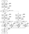
図3は、MFP100のビットマップ画像データをオブジェクト毎に保存するためのフローチャートである。
FIG. 3 is a flowchart for storing bitmap image data of
MFP100において、前記ビットマップ画像データは、画像読み取り部110により取得される。または、ローカルPC102上において、アプリケーションソフトで作成されたドキュメントをMFP100内部でレンダリングして生成される。
In the
まず、ステップS301において、オブジェクト分割が行われる。ここでオブジェクト分割後のオブジェクトの種類は、文字、写真、グラフィック(図面、線画、表)、背景、であるものとする。分割された各々のオブジェクトは、ビットマップデータのままで、ステップS302において、オブジェクトの種類(文字、写真、グラフィック、背景)を判定する。写真の場合、ステップS303において、ビットマップのままJPEG圧縮される。また、背景の場合も同様に、ステップS303において、ビットマップのままJPEG圧縮される。 First, in step S301, object division is performed. Here, it is assumed that the types of objects after the object division are characters, photographs, graphics (drawings, line drawings, tables), and backgrounds. Each divided object remains as bitmap data, and in step S302, the object type (character, photograph, graphic, background) is determined. In the case of a photograph, in step S303, JPEG compression is performed with the bit map unchanged. Similarly, in the case of the background, in step S303, JPEG compression is performed with the bitmap maintained.
次に、オブジェクト判定の結果が、グラフィックの場合、ステップS304において、ベクトル化処理され、パス化されたデータに変換される。最後に、オブジェクト判定の結果が、文字の場合も、ステップS304において、グラフィックと同様にベクトル化処理され、パス化されたデータに変換される。 Next, when the result of the object determination is a graphic, in step S304, it is vectorized and converted to pass data. Finally, when the result of the object determination is a character, in step S304, the vectorization process is performed in the same manner as the graphic, and the data is converted to pass data.
更に、文字の場合には、ステップS308において、ベクトル化処理またはOCR処理が施される。このベクトル化処理はS304で用いられたものと同じものである。OCR処理が施されたデータに関しては文字コード化されたデータに変換される。全てのオブジェクトデータと、文字コード化されたデータが一つのファイルとしてまとめられる。 Further, in the case of characters, vectorization processing or OCR processing is performed in step S308. This vectorization process is the same as that used in S304. The data that has been subjected to the OCR process is converted into data that has been character-coded. All object data and character-coded data are collected as one file.
次に、ステップS305において、各オブジェクトに対して、最適なメタデータが付与される。メタデータが付与された各々のオブジェクトは、ステップS306において、MFP100に内蔵されているBOXに保存される。保存されたデータは、ステップS307において、UI画面に表示される。
In step S305, optimal metadata is assigned to each object. Each object to which metadata is added is stored in a BOX built in
[ビットマップ画像データの作成]
ここで、図3のS301にてオブジェクト分割されるイメージデータの入力方法について述べる。
以下のように2つのケースがあるビットマップ画像データ作成について図5、6を用いて説明する。
(a)MFP100の画像読み取り部入力の場合
MFP100の画像読み取り部を使用した場合には、図5のステップS501において、画像を読み込む。読み込まれた画像は、既にビットマップ画像データである。そのビットマップ画像データをステップS502において、スキャナに依存する画像処理を行う。スキャナに依存する画像処理とは、例えば、色処理やフィルタ処理を指す。
(b)PC102上のアプリケーションソフトを使用した場合
PC102上のアプリケーションソフトを使用して作成したアプリデータは、図6のステップS601において、PC102上にあるプリントドライバを介して、プリントデータに変換され、MFP100に送信される。ここで言うプリントデータとは、PDLデータを意味し、例えば、LIPS、Postscript等によるものを指す。
[Create bitmap image data]
Here, a method for inputting image data to be divided into objects in S301 of FIG. 3 will be described.
The creation of bitmap image data having two cases as described below will be described with reference to FIGS.
(A) In case of input of image reading unit of
(B) When using application software on the
次にステップS602において、MFP100内部に存在するインタープリタを介して、ディスプレイリストが生成される。そのディスプレイリストをステップ603において、レンダリングすることにより、ビットマップ画像データが生成される。
In step S <b> 602, a display list is generated via an interpreter that exists in the
上記2つの例により生成されたビットマップ画像データは、前述のステップ301において、オブジェクト分割される。
The bitmap image data generated by the above two examples is divided into objects in
〔メタデータ付け(ステップS305)〕
ここでは前述のステップS305におけるメタデータ付けの詳細を、図4を用いて説明する。
[Metadata addition (step S305)]
Here, details of adding metadata in step S305 will be described with reference to FIG.
図4は、ステップS305のメタデータ付けに関するフローチャートである。 FIG. 4 is a flowchart relating to metadata attachment in step S305.
まず、ステップS401において、そのオブジェクトの周囲で一番近くに存在する文字オブジェクトを選択する。 First, in step S401, a character object present closest to the object is selected.
次に、ステップS402において、選択された文字オブジェクトに対して、ステップ402において、形態素解析を行う。その形態素解析結果により抽出された単語をメタデータとして、ステップ403において、各オブジェクトに付加する。なお、メタデータの作成には、形態素解析だけではなく、画像特徴量抽出、構文解析等により、作成できることは言うまでもない。 Next, in step S402, morphological analysis is performed on the selected character object in step 402. In step 403, the word extracted based on the morphological analysis result is added as metadata to each object. Needless to say, metadata can be created not only by morphological analysis but also by image feature extraction, syntax analysis, and the like.
[ベクトル化されたデータの詳細]
ここでは図3のベクトル化処理S304でベクトル化されたデータの具体例として、ベクトル化されたデータのフォーマットの一例を図19に示す。なお、本実施形態では、SVG形式で表記しているが、これに限定されるものではない。
[Details of vectorized data]
Here, as a specific example of the data vectorized in the vectorization processing S304 of FIG. 3, an example of the format of the vectorized data is shown in FIG. In this embodiment, the SVG format is used, but the present invention is not limited to this.
図19では説明のため、オブジェクトの表記を枠で囲っている。枠:1901はイメージ属性を示し、そこには、イメージオブジェクトの領域を示す領域情報とこのイメージオブジェクトのビットマップ情報が示されている。枠:1902はテキストオブジェクトの情報が示され、枠:1903では、枠:1902で示した内容をベクターオブジェクトとして表現している。続く、枠:1904は、表オブジェクトなどのラインアートを表す。 In FIG. 19, the object notation is surrounded by a frame for the sake of explanation. A frame: 1901 indicates an image attribute, in which area information indicating an area of the image object and bitmap information of the image object are displayed. A frame: 1902 indicates text object information, and a frame: 1903 expresses the content indicated by the frame: 1902 as a vector object. A subsequent frame: 1904 represents line art such as a table object.
[オブジェクト分割ステップ]
次に、前述のステップS301におけるオブジェクト分割の詳細について説明する。
[Object division step]
Next, details of the object division in step S301 will be described.
ステップS301(オブジェクト分割ステップ)においては、図7右半部の画像702に示すように、入力画像を属性ごとに矩形ブロックに分割する。前述のように、矩形ブロックの属性としては、文字、写真、グラフィック(図面、線画、表など)がある。 In step S301 (object division step), as shown in the image 702 in the right half of FIG. 7, the input image is divided into rectangular blocks for each attribute. As described above, the attributes of rectangular blocks include characters, photographs, and graphics (drawings, line drawings, tables, etc.).
オブジェクト分割ステップにおいては、まず、RAM(不図示)に格納されたイメージデータを白黒に2値化し、黒画素輪郭で囲まれる画素塊を抽出する。 In the object dividing step, first, image data stored in a RAM (not shown) is binarized into black and white, and a pixel block surrounded by a black pixel outline is extracted.
さらに、このように抽出された黒画素塊の大きさを評価し、大きさが所定値以上の黒画素塊の内部にある白画素塊に対する輪郭追跡を行う。白画素塊に対する大きさ評価、内部黒画素塊の追跡というように、内部の画素塊が所定値以上である限り、再帰的に内部画素塊の抽出、輪郭追跡を行う。画素塊の大きさは、例えば画素塊の面積によって評価される。 Further, the size of the black pixel block extracted in this way is evaluated, and the contour tracking is performed for the white pixel block inside the black pixel block whose size is a predetermined value or more. As long as the internal pixel block is equal to or greater than a predetermined value, such as size evaluation for the white pixel block and tracking of the internal black pixel block, the internal pixel block is extracted recursively and the contour is traced. The size of the pixel block is evaluated by, for example, the area of the pixel block.
このようにして得られた画素塊に外接する矩形ブロックを生成し、矩形ブロックの大きさ、形状に基づき属性を判定する。 A rectangular block circumscribing the pixel block thus obtained is generated, and attributes are determined based on the size and shape of the rectangular block.
例えば、縦横比が1に近く、大きさが一定の範囲の矩形ブロックは文字領域矩形ブロックの可能性がある文字相当ブロックとする。近接する文字相当ブロックが規則正しく整列しているときに、これら文字相当ブロックを纏めた新たな矩形ブロックを生成し、新たな矩形ブロックを文字領域矩形ブロックとする。 For example, a rectangular block having an aspect ratio close to 1 and having a constant size is assumed to be a character equivalent block that may be a character area rectangular block. When adjacent character-corresponding blocks are regularly arranged, a new rectangular block in which these character-corresponding blocks are collected is generated, and the new rectangular block is set as a character area rectangular block.
また扁平な画素塊を、もしくは一定大きさ以上でかつ四角形の白画素塊を整列よく内包する黒画素塊をグラフィック領域矩形ブロック、それ以外の不定形の画素塊を写真領域矩形ブロックとする。 In addition, a flat pixel block or a black pixel block that is not less than a certain size and includes square white pixel blocks in a well-aligned manner is defined as a graphic area rectangular block, and other irregular pixel blocks are defined as a photo area rectangular block.
オブジェクト分割ステップでは、このようにして生成された矩形ブロックのそれぞれについて、図8に示すような、属性等のブロック情報および入力ファイル情報を生成する。 In the object dividing step, block information such as attributes and input file information as shown in FIG. 8 are generated for each of the rectangular blocks generated in this way.
図8において、ブロック情報には各ブロックの属性、位置の座標X、座標Y、幅W、高さH、OCR情報が含まれる。属性は1〜3の数値で与えられ、1は文字領域矩形ブロック、2は写真領域矩形ブロック、3はグラフィック領域矩形ブロックを示す。座標X、座標Yは入力画像における各矩形ブロックの始点のX、Y座標(左上角の座標)である。幅W、高さHは矩形ブロックのX座標方向の幅、Y座標方向の高さである。OCR情報は入力画像におけるポインタ情報の有無を示す。さらに入力ファイル情報として矩形ブロックの個数を示すブロック総数Nが含まれる。 In FIG. 8, the block information includes the attribute of each block, position coordinates X, coordinates Y, width W, height H, and OCR information. The attribute is given by a numerical value of 1 to 3, where 1 is a character area rectangular block, 2 is a photo area rectangular block, and 3 is a graphic area rectangular block. The coordinates X and Y are the X and Y coordinates (upper left corner coordinates) of the start point of each rectangular block in the input image. The width W and the height H are the width in the X coordinate direction and the height in the Y coordinate direction of the rectangular block. The OCR information indicates the presence or absence of pointer information in the input image. Furthermore, the total number N of blocks indicating the number of rectangular blocks is included as input file information.
これらの矩形ブロックごとのブロック情報は、特定領域でのベクトル化に利用される。またブロック情報によって、特定領域とその他の領域を合成する際の相対位置関係を特定でき、入力画像のレイアウトを損なわずにベクトル化領域とラスターデータ領域を合成することが可能となる。 The block information for each rectangular block is used for vectorization in a specific area. Further, the relative positional relationship when the specific area and other areas are combined can be specified by the block information, and the vectorized area and the raster data area can be combined without impairing the layout of the input image.
[ベクトル化ステップ]
次いで、前述のステップS304におけるベクトル化処理の詳細について、図9を用いて説明する。このステップS304(ベクトル化ステップ)の処理は、具体的には図9の各ステップによって実行される。
[Vectorization step]
Next, details of the vectorization process in step S304 will be described with reference to FIG. The process of step S304 (vectorization step) is specifically executed by each step of FIG.
ステップS901:特定領域が文字領域矩形ブロックであるか否か判断し、文字領域矩形ブロックであればステップS902以下のステップに進み、周知のパターンマッチングの一手法を用いて認識を行い、対応する文字コードを得る。特定領域が文字領域矩形ブロックでないときは、ステップS912に移行する。 Step S901: It is determined whether or not the specific area is a character area rectangular block. If the specific area is a character area rectangular block, the process proceeds to step S902 and the subsequent steps, and recognition is performed using a well-known pattern matching method. Get the code. If the specific area is not a character area rectangular block, the process proceeds to step S912.
ステップS902:特定領域に対し横書き、縦書きの判定(組み方向判定)をおこなうために、特定領域内で画素値に対する水平・垂直の射影を取る。 Step S902: In order to perform horizontal writing and vertical writing determination (assembling direction determination) on the specific area, a horizontal / vertical projection of the pixel value is taken within the specific area.
ステップS903:ステップS902で求めた射影の分散を評価する。水平射影の分散が大きい場合は横書き、垂直射影の分散が大きい場合は縦書きと判断する。 Step S903: Evaluate the dispersion of the projection obtained in step S902. If the horizontal projection variance is large, it is determined as horizontal writing, and if the vertical projection variance is large, it is determined as vertical writing.
ステップS904:ステップS903の評価結果に基づき、組み方向を判定し、行の切り出しを行い、その後切出した行からさらに文字を切り出して文字画像を得る。 Step S904: Based on the evaluation result of step S903, the assembling direction is determined, a line is cut out, and then a character is cut out from the cut out line to obtain a character image.
文字列および文字への分解は、横書きならば水平方向の射影を利用して行を切り出し、切り出された行に対する垂直方向の射影から、文字を切り出す。縦書きの文字領域に対しては、水平と垂直について逆の処理を行う。行、文字切り出しに際して、文字のサイズも検出し得る。 In the case of horizontal writing, character strings and characters are cut out using horizontal projection, and characters are cut out from the projection in the vertical direction with respect to the cut lines. For vertically written character areas, the process is reversed for horizontal and vertical. When cutting out lines and characters, the size of characters can also be detected.
ステップS905:ステップS904で切り出された各文字について、文字画像から得られる特徴を数十次元の数値列に変換した観測特徴ベクトルを生成する。この観測特徴ベクトルの抽出には種々の公知手法があり、例えば、文字をメッシュ状に分割し、各メッシュ内の文字線を方向別に線素としてカウントしたメッシュ数次元ベクトルを特徴ベクトルとする方法がある。 Step S905: For each character cut out in step S904, an observation feature vector is generated by converting the feature obtained from the character image into a numerical sequence of tens of dimensions. There are various known methods for extracting the observed feature vector. For example, there is a method in which a character is divided into meshes, and a mesh number-dimensional vector obtained by counting character lines in each mesh as line elements according to directions is used as a feature vector. is there.
ステップS906:ステップS905で得られた観測特徴ベクトルと、あらかじめフォントの種類ごとに求められている辞書特徴ベクトルとを比較し、観測特徴ベクトルと辞書特徴ベクトルとの距離を算出する。 Step S906: The observation feature vector obtained in step S905 is compared with the dictionary feature vector obtained in advance for each font type, and the distance between the observation feature vector and the dictionary feature vector is calculated.
ステップS907:ステップS906で算出された各特徴ベクトル間の距離を評価し、最も距離の近いフォントの種類を認識結果とする。 Step S907: The distance between each feature vector calculated in step S906 is evaluated, and the type of font having the closest distance is used as the recognition result.
ステップS908:ステップS907における距離評価において、最短距離が所定値よりも大きいか否か、類似度を判断する。類似度が所定値以上の場合は、辞書特徴ベクトルにおいて、形状が類似する他の文字に誤認識している可能性が高い。そこで類似度が所定値以上の場合は、ステップS907の認識結果を採用せず、ステップS911に進む。類似度が所定値より低い(小さい)ときは、ステップS907の認識結果を採用し、ステップ909に進む。 Step S908: In the distance evaluation in step S907, it is determined whether or not the shortest distance is larger than a predetermined value. When the similarity is equal to or greater than a predetermined value, there is a high possibility that the dictionary feature vector is erroneously recognized as another character having a similar shape. Therefore, if the similarity is greater than or equal to a predetermined value, the recognition result of step S907 is not adopted, and the process proceeds to step S911. When the similarity is lower (smaller) than the predetermined value, the recognition result in step S907 is adopted, and the process proceeds to step 909.
ステップS909(フォント認識ステップ):文字認識の際に用いる、フォントの種類数分の辞書特徴ベクトルを、文字形状種すなわちフォント種に対して複数用意しておく。パターンマッチングの際に、文字コードとともに前記辞書特徴ベクトルのフォント種を出力することで、文字フォントを認識し得る。 Step S909 (font recognition step): A plurality of dictionary feature vectors corresponding to the number of font types used for character recognition are prepared for character shape types, that is, font types. At the time of pattern matching, the font type of the dictionary feature vector is output together with the character code, so that the character font can be recognized.
ステップS910:文字認識およびフォント認識よって得られた文字コードおよびフォント情報を用いて、各々あらかじめ用意されたアウトラインデータを用いて、各文字をベクトルデータに変換する。なお、入力画像がカラーの場合は、カラー画像から各文字の色を抽出してベクトルデータとともに記録する。 Step S910: Using the character code and font information obtained by character recognition and font recognition, each character is converted into vector data using outline data prepared in advance. When the input image is color, the color of each character is extracted from the color image and recorded together with vector data.
ステップS911:文字を一般的なグラフィックと同様に扱い、この文字をアウトライン化する。すなわち誤認識を起こす可能性の高い文字については、イメージデータに可視的に忠実なアウトラインのベクトルデータを生成する。 Step S911: Characters are handled in the same way as general graphics, and the characters are outlined. In other words, outline vector data that is visually faithful to the image data is generated for characters that are likely to cause erroneous recognition.
ステップS912:特定領域が文字領域矩形ブロックでないときは、画像の輪郭に基づいてベクトル化の処理を実行する。 Step S912: When the specific area is not a character area rectangular block, vectorization processing is executed based on the contour of the image.
以上の処理により、文字領域矩形ブロックに属するイメージ情報をほぼ形状、大きさ、色が忠実なベクトルデータに変換出来る。 Through the above processing, the image information belonging to the character area rectangular block can be converted into vector data that is substantially faithful in shape, size, and color.
[グラフィック領域のベクトル化]
ステップS302にて、文字領域矩形ブロック以外の領域、すなわちグラフィック領域矩形ブロックと判断されたときは、特定領域内で抽出された黒画素の塊の輪郭をベクトルデータに変換する。
[Vectorization of graphic area]
If it is determined in step S302 that the area is other than the character area rectangular block, that is, the graphic area rectangular block, the outline of the black pixel block extracted in the specific area is converted into vector data.
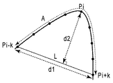
文字領域以外の領域のベクトル化においては、まず線画等を直線および/または曲線の組み合わせとして表現するために、曲線を複数の区間(画素列)に区切る「角」を検出する。角とは曲率が極大となる点であり、例えば図10に示す曲線上の画素Piが角か否かの判断は以下のように行う。 In vectorization of regions other than character regions, first, “corners” that divide a curve into a plurality of sections (pixel columns) are detected in order to represent a line drawing or the like as a combination of straight lines and / or curves. A corner is a point at which the curvature is maximized. For example, whether or not the pixel Pi on the curve shown in FIG. 10 is a corner is determined as follows.
すなわち、Piを起点とし、曲線に沿ってPiから両方向に所定画素(ここではk個とする)ずつ離れた画素Pi−k、Pi+kを線分Lで結ぶ。画素Pi−k、P i+k間の距離をd1、線分Lと画素Piとの距離をd2、曲線の画素Pi−k 、Pi+k間の弧の長さをAとする。d2が極大となるとき、あるいは比(d1/A)が閾値以下となるときに画素Piを角と判断する。 That is, pixels Pi-k and Pi + k that are separated from each other by a predetermined number of pixels (here, k pixels) in both directions along Pi are connected by a line segment L. The distance between the pixels Pi-k and Pi + k is d1, the distance between the line segment L and the pixel Pi is d2, and the arc length between the curved pixels Pi-k and Pi + k is A. When d2 reaches a maximum or when the ratio (d1 / A) is equal to or less than the threshold, the pixel Pi is determined to be a corner.
角によって分割された画素列を、直線あるいは曲線で近似する。直線への近似は最小二乗法等により実行し、曲線への近似は3次スプライン関数などを用いる。画素列を分割する角の画素は近似直線あるいは近似直線における、始端または終端となる。 The pixel row divided by the corner is approximated by a straight line or a curve. The approximation to a straight line is executed by the least square method or the like, and the approximation to a curve uses a cubic spline function or the like. The pixel at the corner that divides the pixel row is the approximate line or the start or end of the approximate line.
さらにベクトル化された輪郭内に白画素塊の内輪郭が存在するか否かを判断し、内輪郭が存在するときはその輪郭をベクトル化し、内輪郭の内輪郭というように、再帰的に反転画素の内輪郭をベクトル化する。 Furthermore, it is judged whether or not the inner contour of the white pixel block exists in the vectorized contour, and when there is an inner contour, the contour is vectorized and recursively inverted as the inner contour of the inner contour. The inner contour of the pixel is vectorized.
以上のように、輪郭の区分線近似を用いれば、任意形状の図形のアウトラインをベクトル化することができる。元原稿がカラーの場合は、カラー画像から図形の色を抽出して抽出した色情報をベクトルデータとともに記録する。 As described above, the outline of a figure having an arbitrary shape can be vectorized by using the contour line approximation. When the original document is color, the color information extracted by extracting the color of the figure from the color image is recorded together with the vector data.
図11に示すように、ある注目区間で外輪郭PRjと、内輪郭PRj+1あるいは別の外輪郭が近接している場合、2個あるいは複数の輪郭線をひとまとめにし、太さを持った線として表現することができる。例えば、輪郭PRj+1の各画素Piから輪郭PRj上で最短距離となる画素Qiまでの距離PQiを算出し、PQiのばらつきがわずかである場合には、注目区間を画素Pi、Qiの中点Miの点列に沿った直線または曲線で近似し得る。近似直線、近似曲線の太さは、例えば距離PQiの平均値とする。 As shown in FIG. 11, when the outer contour PRj and the inner contour PRj + 1 or another outer contour are close to each other in a certain section of interest, two or a plurality of contour lines are combined and expressed as a line having a thickness. can do. For example, the distance PQi from each pixel Pi of the contour PRj + 1 to the pixel Qi that is the shortest distance on the contour PRj is calculated, and when the variation in PQi is slight, the attention interval is set to the midpoint Mi of the pixels Pi and Qi It can be approximated by a straight line or curve along the point sequence. The thickness of the approximate line and the approximate curve is, for example, an average value of the distance PQi.
線や線の集合体である表罫線は、太さを持つ線の集合とすることにより、効率よくベクトル表現することができる。 A table ruled line, which is a line or a set of lines, can be efficiently expressed as a vector by using a set of lines having a thickness.
輪郭まとめの処理の後、全体の処理を終了する。 After the outline summarization process, the entire process is terminated.
なお写真領域矩形ブロックについては、ベクトル化せず、イメージデータのままとする。 Note that the photographic area rectangular block is not vectorized and remains as image data.
[図形認識]
以上のように線図形等のアウトラインをベクトル化した後、ベクトル化された区分線を図形オブジェクトごとにグループ化する。
[Figure recognition]
As described above, after the outline of a line figure or the like is vectorized, the vectorized dividing lines are grouped for each graphic object.
以下に説明する図12の各ステップは、ベクトルデータを図形オブジェクトごとにグループ化する処理を示す。 Each step of FIG. 12 described below indicates a process of grouping vector data for each graphic object.
ステップS1201:まず各ベクトルデータの始点、終点を算出する。 Step S1201: First, the start point and end point of each vector data are calculated.
ステップS1202(図形要素検出):ステップS1201で求められた始点、終点情報を用いて、図形要素を検出する。図形要素とは、区分線が構成している閉図形であり、検出に際しては、始点、終端となっている共通の角の画素においてベクトルを連結する。すなわち、閉形状を構成する各ベクトルはその両端にそれぞれ連結するベクトルを有しているという原理を応用する。 Step S1202 (graphic element detection): A graphic element is detected using the start point and end point information obtained in step S1201. A graphic element is a closed graphic formed by a dividing line, and a vector is connected at a common corner pixel serving as a start point and an end point for detection. That is, the principle that each vector constituting the closed shape has a vector connected to both ends thereof is applied.
ステップS1203:次に図形要素内に存在する他の図形要素、もしくは区分線をグループ化し、一つの図形オブジェクトとする。また、図形要素内に他の図形要素、区分線が存在しない場合は図形要素を図形オブジェクトとする。 Step S1203: Next, other graphic elements or dividing lines existing in the graphic element are grouped into one graphic object. If there is no other graphic element or dividing line in the graphic element, the graphic element is set as a graphic object.
[図形要素の検出]
上記ステップS1202(図形要素検出)の処理は、具体的には図13の各ステップによって実行される。
[Detection of graphic elements]
The process of step S1202 (graphic element detection) is specifically executed by each step of FIG.
ステップS1301:まず、ベクトルデータより両端に連結していない不要なベクトルを除去し、閉図形を構成するベクトルを抽出する。 Step S1301: First, unnecessary vectors that are not connected to both ends are removed from vector data, and a vector constituting a closed figure is extracted.
ステップS1302:次に閉図形を構成するベクトルについて、いずれかのベクトルの端点(始点または終点)を開始点とし、一定方向、例えば時計回りに、順にベクトルを探索する。すなわち、他端点において他のベクトルの端点を探索し、所定距離内の最近接端点を連結ベクトルの端点とする。閉図形を構成するベクトルを1まわりして開始点に戻ったとき、通過したベクトルを全て一つの図形要素を構成する閉図形としてグループ化する。また、閉図形内部にある閉図形構成ベクトルも全てグループ化する。さらにまだグループ化されていないベクトルの始点を開始点とし、同様の処理を繰り返す。 Step S1302: Next, for the vectors constituting the closed figure, the vectors are searched in order in a certain direction, for example, clockwise, with the end point (start point or end point) of one of the vectors as the start point. That is, the end point of another vector is searched at the other end point, and the closest end point within a predetermined distance is set as the end point of the connected vector. When the vector constituting the closed figure is rotated by one and returned to the starting point, all the passed vectors are grouped as a closed figure constituting one graphic element. In addition, all closed graphic constituent vectors inside the closed graphic are also grouped. Further, the same processing is repeated with the starting point of a vector not yet grouped as a starting point.
ステップS1303:最後に、ステップS1301で除去された不要ベクトルのうち、ステップS1302で閉図形としてグループ化されたベクトルに端点が近接しているベクトルを検出し、一つの図形要素としてグループ化する。 Step S1303: Finally, from the unnecessary vectors removed in Step S1301, a vector whose end point is close to the vector grouped as a closed graphic in Step S1302 is detected and grouped as one graphic element.
以上の処理によって図形ブロックを、再利用可能な個別の図形オブジェクトとして扱うことが可能になる。 With the above processing, a graphic block can be handled as a reusable individual graphic object.
[BOX保存処理]
次いで、前述したステップS306のBOX保存の詳細について説明する。
[BOX saving process]
Next, details of the BOX storage in step S306 described above will be described.
図3のオブジェクト分割ステップ(ステップS301)の後、ベクトル化(ステップS304)した結果のデータを用いて、BOX保存データへの変換処理が実行される。本実施形態では、ステップS304のベクトル化処理結果は図14に示す中間データの形式、いわゆるドキュメント・アナリシス・アウトプット・フォーマット(以下、DAOF)と呼ばれる形式で保存されている。 After the object division step (step S301) in FIG. 3, conversion processing to BOX storage data is executed using data obtained as a result of vectorization (step S304). In the present embodiment, the vectorization processing result in step S304 is stored in the intermediate data format shown in FIG. 14, that is, the so-called document analysis output format (hereinafter referred to as DAOF).
図14において、DAOFは、ヘッダ1401、レイアウト記述データ部1402、文字認識記述データ部1403、表記述データ部1404、画像記述データ部1405よりなる。
14, DAOF includes a
ヘッダ1401には、処理対象の入力画像に関する情報が保持される。
The
レイアウト記述データ部1402には、入力画像中の矩形ブロックの属性である文字、線画、図面、表、写真等の情報と、これら属性が認識された各矩形ブロックの位置情報が保持される。
The layout
文字認識記述データ部1403には、文字領域矩形ブロックのうち、文字認識して得られる文字認識結果が保持される。
The character recognition
表記述データ部1404には、表の属性を持つグラフィック領域矩形ブロックの表構造の詳細が格納される。
The table
画像記述データ部1405には、グラフィック領域矩形ブロックにおけるイメージデータが、入力画像データから切り出して保持される。
In the image
ベクトル化処理を指示された特定領域においては、ベクトル化処理により得られたブロックに対して、画像記述データ部1405には、そのブロックの内部構造や、画像の形状や文字コード等を表すデータの集合が保持される。
In the specific area where vectorization processing is instructed, the image
一方、ベクトル化処理の対象ではない、特定領域以外の矩形ブロックでは、入力画像データそのものが保持される。 On the other hand, the input image data itself is held in a rectangular block other than the specific area that is not a vectorization target.
ここで、BOX保存データへの変換処理について図15〜18を用いて説明する。 Here, the conversion process to BOX preservation | save data is demonstrated using FIGS.
BOX保存データへの変換処理は図15に示す各ステップにより実行される。 Conversion processing to BOX storage data is executed by each step shown in FIG.
ステップS1501(図15):DAOF形式のデータを入力する。 Step S1501 (FIG. 15): Data in DAOF format is input.
ステップS1502:アプリデータの元となる文書構造ツリー生成を行う。 Step S1502: Generate a document structure tree that is the source of application data.
ステップS1503:文書構造ツリーを元に、DAOF内の実データを取得し、実際のアプリデータを生成する。 Step S1503: Based on the document structure tree, actual data in the DAOF is acquired, and actual application data is generated.
このステップS1502の文書構造ツリー生成処理は、図16の各ステップにより実行される。図16の処理における全体制御の基本ルールとして、処理の流れはミクロブロック(単一矩形ブロック)からマクロブロック(矩形ブロックの集合体)へ移行する。以後「矩形ブロック」は、ミクロブロックおよびマクロブロック両者を意味するものとする。 The document structure tree generation process in step S1502 is executed by each step in FIG. As a basic rule of overall control in the processing of FIG. 16, the flow of processing shifts from a micro block (single rectangular block) to a macro block (aggregate of rectangular blocks). Hereinafter, “rectangular block” means both a micro block and a macro block.
ステップS1601(図16):矩形ブロック単位で、縦方向の関連性に基づいて、矩形ブロックを再グループ化する。図16の処理は繰り返し実行されることがあるが、処理開始直後はミクロブロック単位での判定となる。 Step S1601 (FIG. 16): The rectangular blocks are regrouped in units of rectangular blocks based on the relevance in the vertical direction. Although the process of FIG. 16 may be repeatedly executed, the determination is performed in units of micro blocks immediately after the start of the process.
ここで、関連性とは、距離が近い、ブロック幅(横方向の場合は高さ)がほぼ同一であることなどの特徴によって定義される。また、距離、幅、高さなどの情報はDAOFを参照し、抽出する。 Here, the relevance is defined by characteristics such as a short distance and a substantially equal block width (height in the horizontal direction). Information such as distance, width, and height is extracted with reference to DAOF.
一例として示す図17のイメージデータでは、最上部で、矩形ブロックT1、T2が横方向に並列されている。矩形ブロックT1、T2の下には横方向セパレータS1が存在し、横方向セパレータS1の下に矩形ブロックT3、T4、T5、T6、T7が存在する。 In the image data of FIG. 17 shown as an example, rectangular blocks T1 and T2 are juxtaposed in the horizontal direction at the top. A horizontal separator S1 exists below the rectangular blocks T1 and T2, and rectangular blocks T3, T4, T5, T6, and T7 exist below the horizontal separator S1.
矩形ブロックT3、T4、T5は、横方向セパレータS1下側の領域における左半部において上から下に、縦方向に配列され、矩形ブロックT6、T7は、横方向セパレータS1下側の領域における右半部において上下に配列されている。 The rectangular blocks T3, T4, and T5 are arranged in the vertical direction from top to bottom in the left half of the region below the horizontal separator S1, and the rectangular blocks T6 and T7 are arranged in the right side in the region below the horizontal separator S1. They are arranged vertically in the half.
このようなイメージデータに対し、ステップS1601の縦方向の関連性に基づくグルーピングの処理を実行する。これによって、矩形ブロックT3、T4、T5が1個のグループ(矩形ブロック)V1にまとめられ、矩形ブロックT6、T7が1個のグループ(矩形ブロック)V2にまとめられる。グループV1、V2は同一階層となる。 For such image data, a grouping process based on the vertical relevance in step S1601 is executed. As a result, the rectangular blocks T3, T4, and T5 are combined into one group (rectangular block) V1, and the rectangular blocks T6 and T7 are combined into one group (rectangular block) V2. The groups V1 and V2 are in the same hierarchy.
ステップS1602:縦方向のセパレータの有無をチェックする。セパレータは、DAOF中でライン属性を持つオブジェクトであり、アプリケーションソフトウエア中で明示的にブロックを分割する機能をもつ。セパレータを検出すると、処理対象の階層において、入力画像の領域を、セパレータを境界として左右に分割する。図17の例では縦方向のセパレータは存在しない。 Step S1602: The presence / absence of a vertical separator is checked. The separator is an object having a line attribute in the DAOF, and has a function of explicitly dividing the block in the application software. When the separator is detected, the area of the input image is divided into left and right with the separator as a boundary in the processing target hierarchy. In the example of FIG. 17, there is no vertical separator.
ステップS1603:縦方向のグループ高さの合計が入力画像の高さに等しくなったか否か判断する。すなわち縦方向(例えば上から下へ。)に処理対象の領域を移動しながら、横方向のグルーピングを行うとき、入力画像全体の処理が終了したときには、グループ高さ合計が入力画像高さになることを利用し、処理の終了判断を行う。グルーピングが終了したときはそのまま処理終了し、グルーピングが終了していなかったときはステップS1604に進む。 Step S1603: It is determined whether or not the total group height in the vertical direction is equal to the height of the input image. That is, when grouping in the horizontal direction while moving the region to be processed in the vertical direction (for example, from top to bottom), when the processing of the entire input image is completed, the total group height becomes the input image height. To determine the end of the process. When the grouping is finished, the process is finished as it is, and when the grouping is not finished, the process proceeds to step S1604.
ステップS1604:横方向の関連位に基づくグルーピングの処理を実行する。これによって、矩形ブロックT1、T2が1個のグループ(矩形ブロック)H 1にまとめられ、矩形ブロックV1、V2が1個のグループ(矩形ブロック)H 2にまとめられる。グループH1、H2は同一階層となる。ここでも、処理開始直後はミクロブロック単位での判定となる。 Step S1604: A grouping process based on the related position in the horizontal direction is executed. As a result, the rectangular blocks T1 and T2 are combined into one group (rectangular block) H1, and the rectangular blocks V1 and V2 are combined into one group (rectangular block) H2. The groups H1 and H2 are in the same hierarchy. Again, immediately after the start of processing, the determination is made in units of micro blocks.
ステップS1605:横方向のセパレータの有無をチェックする。セパレータを検出すると、処理対象の階層において、入力画像の領域を、セパレータを境界として上下に分割する。図17では横方向のセパレータS1が存在する。 Step S1605: Check for the presence of a horizontal separator. When the separator is detected, the area of the input image is divided into upper and lower parts with the separator as a boundary in the processing target hierarchy. In FIG. 17, there is a horizontal separator S1.
以上の処理結果は図18に示すツリーとして登録される。 The above processing results are registered as a tree shown in FIG.
図18において、入力画像V0は、最上位階層にグループH1、H2、セパレータS1を有し、グループH1には第2階層の矩形ブロックT1、T2が属する。グループH2には、第2階層のグループV1、V2が属し、グループV1には、第3階層の矩形ブロックT3、T4、T5が属し、グループV2には、第3階層の矩形ブロックT6、T7が属する。 In FIG. 18, the input image V0 has groups H1 and H2 and a separator S1 in the highest layer, and rectangular blocks T1 and T2 in the second layer belong to the group H1. The group H2 includes the second layer groups V1 and V2, the group V1 includes the third layer rectangular blocks T3, T4, and T5, and the group V2 includes the third layer rectangular blocks T6 and T7. Belongs.
ステップS1606:横方向のグループ長合計が入力画像の幅に等しくなったか否か判断する。これによって横方向のグルーピングに関する終了判断を行う。横方向のグループ長がページ幅となっている場合は、文書構造ツリー生成の処理を終了する。横方向のグループ長がページ幅となっていないときは、ステップS1601に戻り、再びもう一段上の階層で、縦方向の関連性チェックから繰り返す。 Step S1606: It is determined whether or not the total group length in the horizontal direction is equal to the width of the input image. In this way, the end determination regarding the grouping in the horizontal direction is performed. If the horizontal group length is the page width, the document structure tree generation process is terminated. If the group length in the horizontal direction is not the page width, the process returns to step S1601, and the relevance check in the vertical direction is repeated again at the next higher level.
[表示方法]
次に、図3のS307に示したUIに表示に関して、図20〜24を用いて詳細な説明を行う。
[Display method]
Next, the display on the UI shown in S307 of FIG. 3 will be described in detail with reference to FIGS.
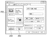
図20にユーザーインターフェースの一例を示す。このユーザーインターフェースは、MFP100が有する表示装置116の例である。しかしながら、ユーザーインターフェースはこれに限るものではなく、マネージメントPC101、または、ネットワークで接続されたローカルPC102が有するアプリケーションを用いて表示するRemoteUIのような表示装置によるものでもよい。
FIG. 20 shows an example of a user interface. This user interface is an example of the
図20において、2001にはBOX内に保存されているデータが表示されている。2002に示すように一つ一つの文章には名前がついており、入力された時間などの情報も表示される。オブジェクト分割表示を行う場合には、2001で原稿を選択して、オブジェクト表示ボタン2003を押すことで表示が変わる。これに関しては、後述する。また、2001で原稿を選択して、ページ表示ボタン2004を押すことでも表示が変わる。これに関しても後述する。
In FIG. 20, 2001 indicates data stored in the BOX. As shown in 2002, each sentence has a name, and information such as the input time is also displayed. When the object division display is performed, the display is changed by selecting a document in 2001 and pressing an
図21にユーザーインターフェースの他の例を示す。図21の2101は、前述のステップS306でBOX保存されたデータの内容を表示する。このユーザーインターフェースでは、ラスタ画像を縮小した画像を表示することや、前述したSVGを使って表示をさせることも可能である。つまり、前述してきたデータを基にページ全体を表示していれば良い。
FIG. 21 shows another example of the user interface.
2102は、MFPの機能を選択するためのタブで、このタブの押下により、コピーや送信、リモート操作、ブラウザー、BOXといったMFPが持っている機能を選択できるものである。これ以外の機能に対しても同様の表示を行うことが出来ることは示すまでもない。
2103は、原稿モードを選択するためのリスト表示であり、原稿を読み取る場合の原稿モードを選択することが出来る。これは原稿タイプによって、画像処理を切り替えるために選択をするものでここに示した以外のモードも同様に表示選択をすることが出来る。2104には、原稿読み取りのスタートのボタンを2104に示している。このボタンの押下により、スキャナが動作して、画像を読み込むことになる。この例では、読込みスタートを画面内に設けているが、別途設けたスタートボタンによって読み込みを開始してもよい。
図22に示すユーザーインターフェースの例は、オブジェクト分割した結果が分かるように、各オブジェクトに枠を表示させるようにしたものである。2201のボタンを押すことにより、ページ表示画面2202に対してそれぞれオブジェクトの枠が表示される。枠には色付けをすることにより、オブジェクトの違いを分かるように表示することや、線の太さ、あるいは、点線、破線の違いなどにより、オブジェクトの違いを分かるように表示を行う。ここでオブジェクトの種類としては、前述したように文字、図面、線画、表、写真等である。
In the example of the user interface shown in FIG. 22, a frame is displayed on each object so that the result of the object division can be understood. By pressing a
2203は検索を行うための文字を入力するのに用いる表示である。ここに文字列を入力して、検索を行うことで、オブジェクトあるいはオブジェクトが含まれるページが検索される。検索方法に関しては、前述したメタデータにより、周知の検索手法を用いることで、オブジェクトあるいはページの検索を行う。そして検索されたオブジェクトあるいはページを表示する。
図23は、2302のオブジェクト表示を押すことによりページ内のオブジェクトが表示される例である。2301に示すように、ページという概念ではなく、一つ一つのオブジェクトが部品として表示が行われる。また、2304のページ表示を押すことで1ページの画像として見えるように切替表示も行える。
FIG. 23 is an example in which an object in the page is displayed by pressing an
さらに、2303は検索を行うための文字を入力するのに用いる表示である。ここに文字列を入力して、検索を行うことで、オブジェクトあるいはオブジェクトが含まれるページが検索される。検索方法に関しては、前述したメタデータにより、周知の検索手法を用いることで、オブジェクトあるいはページの検索を行う。また検索されたオブジェクトあるいはページを表示する。
Further,
図24は、オブジェクトのメタデータを表示した画面の例である。ある一つのオブジェクトを選択するとそのオブジェクトの画像2403と前述したメタデータ2402が表示される。メタデータは、オブジェクトの情報として、エリアID、幅、高さ、属性、ユーザー情報、MFPの設置場所の情報、入力した時間、キャプションなどの情報を表示する。ここで、この例では、写真属性のオブジェクトであり、オブジェクトの近くにあった文字オブジェクトのOCR情報から形態素解析を用いて名詞のみを取り出して表示を行っている、それが図示したTEXTという文字列にあたる。
FIG. 24 is an example of a screen displaying object metadata. When one object is selected, an
また、メタデータに対しては、2404に示す各ボタンにより編集や追加、削除を行うことを可能としている。さらに、2405は検索を行うための文字を入力するのに用いる表示である。ここに文字列を入力して、検索を行うことで、オブジェクトあるいはオブジェクトが含まれるページが検索される。検索方法に関しては、前述したメタデータにより、周知の検索手法を用いることで、オブジェクトあるいはページの検索を行う。また検索されたオブジェクトあるいはページを表示する。 In addition, metadata can be edited, added, or deleted by using buttons shown in 2404. Further, reference numeral 2405 denotes a display used for inputting characters for performing a search. By inputting a character string here and performing a search, an object or a page including the object is searched. As for the search method, an object or page is searched by using a well-known search method based on the above-described metadata. Also, the searched object or page is displayed.
[メタデータの編集]
次に、前記図41で示した選択部137、メタデータ解析部138、メタデータ更新手順決定部139、メタデータ更新部140で行うメタデータの編集について、図25〜34を用いて以下に詳細に説明する。
Edit metadata
Next, metadata editing performed by the
図25は、本実施形態におけるキーボード入力を必要としない、メタデータの編集画面の例である。前述した図21〜23の何れの画面においても、メタデータの編集は可能であるが、ユーザーが理解しやすい画面としては、オブジェクト分割した結果を分かるように各オブジェクトに枠を表示させている図22が望ましい。そのため、図25は、図22と同じ構成でオブジェクトに枠を表示させている。 FIG. 25 is an example of a metadata editing screen that does not require keyboard input in the present embodiment. In any of the screens of FIGS. 21 to 23 described above, metadata can be edited. However, as a screen that is easy for the user to understand, a frame is displayed on each object so that the result of object division can be understood. 22 is desirable. Therefore, FIG. 25 displays a frame on the object with the same configuration as FIG.
ユーザーはこの画面上で、1つのオブジェクトをタッチペン、または、マウスを用いて選択し、選択したオブジェクトを他のオブジェクトにドラッグアンドドロップすることで、メタデータの編集を行う。 On this screen, the user selects one object using the touch pen or the mouse, and edits the metadata by dragging and dropping the selected object onto another object.
図26は、図25の2501の画面の拡大図である。まず、図27の2701〜2706を用いて2601〜2606のオブジェクトのメタデータの説明を行う。
FIG. 26 is an enlarged view of the
図27の2701〜2706は、2601〜2606のオブジェクトの各々のメタデータのデータ形式を示す図である。ここで、メタデータのデータ形式は、前述したSVGのデータ形式、または、XMLのデータ形式のように「タグ」を用いるマークアップ言語が一般的であるため、本実施形態においても、メタデータのデータ形式をマークアップ言語で示している。これらのメタデータのデータ形式は、図24を用いて前述したように、表示用のデータ形式に変換して画面で表示することが可能である。
以下、メタデータのデータ形式に関する説明を、図27の2701を用いて説明する。 Hereinafter, description on the data format of the metadata will be described with reference to 2701 in FIG.
<id>1</id>は、オブジェクト2601のエリアIDを示すデータであり、図24に示されるエリアIDを表示するためのデータである。
<Id> 1 </ id> is data indicating the area ID of the
<attribute>写真</attribute>は、オブジェクト2601の属性を示すデータであり、オブジェクト2601は、写真属性であることを示している。その他、文字や写真やグラフィック等の属性があり、これらは、前述したステップS301にて決定される。
<Attribute> Photo </ attribute> is data indicating an attribute of the
<width>W1</width>は、オブジェクト2601の幅を示すデータであり、図24に示される幅を表示するためのデータである。
<Width> W1 </ width> is data indicating the width of the
<height>H1</height>は、オブジェクト2601の高さを示すデータであり、図24に示される高さを表示するためのデータである。
<Height> H1 </ height> is data indicating the height of the
<job>PDL</job>は、オブジェクト2601のジョブ種であり、前述したようにビットマップデータの生成において、MFP100の画像読み取り部入力の場合は、ジョブ種はSCANとなる。また、PC102上のアプリケーションソフトを使用した場合は、ジョブ種はPDLとなる。
<Job> PDL </ job> is the job type of the
<user>USER1</user>は、オブジェクト2601のユーザー情報を示すデータであり、図24に示されるユーザーを表示するためのデータである。
<User> USER1 </ user> is data indicating the user information of the
<place>F社G階</place>は、MFPの設置場所の情報を示すデータであり、図24に示される場所を表示するためのデータである。 <Place> F company G floor </ place> is data indicating information on the installation location of the MFP, and is data for displaying the location shown in FIG.
<time>2007/03/19 17:09</time>は、入力した時間を示すデータであり、図24に示される時間を表示するためのデータである。 <Time> 2007/03/19 17:09 </ time> is data indicating the input time, and is data for displaying the time shown in FIG.
<caption>一眼レフカメラ</caption>は、オブジェクト2601のキャプションを示すデータであり、図24に示されるキャプションを表示するためのデータである。
<Caption> single-lens reflex camera </ caption> is data indicating the caption of the
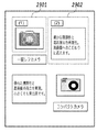
ここで、図28を用いて、ユーザーが図25の画面上で、1つのオブジェクトを選択し、さらに、該オブジェクトを他のオブジェクトにドラッグアンドドロップしたときの各々のオブジェクトのメタデータの付き方に関して説明する。 Here, with reference to FIG. 28, how the metadata of each object is attached when the user selects one object on the screen of FIG. 25 and further drags and drops the object onto another object. explain.
ここで、前述した選択部137において、操作部133でユーザーが最初に選択したオブジェクトを送オブジェクトとし、ドラッグアンドドロップされた他のオブジェクトを受オブジェクトとして選択する。
Here, in the
また、以下では、送オブジェクトを受オブジェクトにドラッグアンドドロップを行う場合について説明する。しかしながら、図29に示すように最初に選択されたオブジェクトを2901で示すように(1)の番号を付けて表示し、次に選択されたオブジェクトを2902で示すように(2)の番号を付けて表示してもよい。そのようにして、送オブジェクトを(1)、受オブジェクトを(2)とし、互いの関係が明示的に表示できるようなユーザーインターフェース(オブジェクト関連付け手段)であれば、ドラッグアンドドロップに限るものではない。 In the following, a case will be described in which a sending object is dragged and dropped onto a receiving object. However, as shown in FIG. 29, the first selected object is displayed with the number (1) as indicated by 2901, and the next selected object is indicated with the number (2) as indicated by 2902. May be displayed. In this way, if the user interface (object association means) is such that the sending object is (1), the receiving object is (2), and the relationship between them can be explicitly displayed, it is not limited to drag and drop. .
まず、ユーザーが、2603のオブジェクトを2601のオブジェクトへドラッグアンドドロップした場合について説明を行う。この場合、前述したように、2603は、送オブジェクト、2601は、受オブジェクトとなる。
First, a case where the user drags and drops the
まず、ステップS2801にて、送オブジェクトとして、2603を選択する。 First, in step S2801, 2603 is selected as the sending object.
次に、ステップS2802にて、ステップS2801において選択された送オブジェクトのメタデータ解析を行う。このメタデータ解析により、2703のメタデータのデータ形式が参照され、2603は、<attribute>文字</attribute>の属性をもっていることがわかる。 Next, in step S2802, metadata analysis of the sending object selected in step S2801 is performed. By this metadata analysis, the data format of 2703 metadata is referred to, and it can be seen that 2603 has an attribute of <attribute> character </ attribute>.
次に、ステップS2803にて、送オブジェクトの属性を判別する。ここで、送オブジェクトの属性は、文字であるためステップS2804へ進む。 In step S2803, the attribute of the sending object is determined. Here, since the attribute of the sending object is a character, the process advances to step S2804.
次に、ステップS2804にて、受オブジェクトとして、2601が選択される。正確には、2603のオブジェクトを2601のオブジェクトへドラッグアンドドロップしているため、2601が受オブジェクトとなる。
Next, in step S2804, 2601 is selected as the receiving object. To be exact, since the
次に、ステップS2805にて、受オブジェクトのメタデータ解析を行う。このメタデータ解析により、2701のメタデータのデータ形式が参照され、2601は、<attribute>写真</attribute>の属性をもっていることがわかる。 Next, in step S2805, metadata analysis of the receiving object is performed. This metadata analysis refers to the data format of 2701 metadata, and it can be seen that 2601 has an attribute of <attribute> photo </ attribute>.
次に、ステップS2806にて、受オブジェクトの属性を判別する。ここで、受オブジェクトの属性は、写真であるためステップS2808へ進む。 Next, in step S2806, the attributes of the receiving object are determined. Here, since the attribute of the receiving object is a photograph, the process advances to step S2808.
次に、ステップS2808にて、受メタデータマージ処理を行う。ここでは、送オブジェクトとして、文字属性のオブジェクト2603が選択され、受オブジェクトとして、写真属性のオブジェクト2601が選択されているため、2601のメタデータ2701のみを図30の3001のように更新する。ここで、2701と比較して、3001は、2703の<caption>豊かな階調性と高彩度な色再現性。高画質へのこだわりに応えます。</caption>部分のメタデータが追記されていることがわかる。
Next, in step S2808, a received metadata merge process is performed. Here, since the
次に、ユーザーが、2601のオブジェクトを2603のオブジェクトへドラッグアンドドロップした場合について説明を行う。この場合、前述したように、2601は、送オブジェクト、2603は、受オブジェクトとなる。送オブジェクトの属性は、写真であり受オブジェクトの属性は、文字であるため、前述した処理を経て、ステップS2812に進む。
Next, a case where the user drags and drops the
ステップS2812にて、送メタデータマージ処理を行う。ここでは、送オブジェクトとして、写真属性のオブジェクト2601が選択され、受オブジェクトとして、文字属性のオブジェクト2603が選択されているため、2601のメタデータ2701のみを図30の3001のように更新する。
In step S2812, transmission metadata merge processing is performed. Here, since the
このように、メタデータの編集を行う際に、文字のオブジェクトを写真のオブジェクトへドラッグアンドドロップした場合と、写真のオブジェクトを文字のオブジェクトへドラッグアンドドロップした場合で、同様のメタデータ編集結果を得ることが可能である。 In this way, when editing metadata, the same metadata editing results can be obtained by dragging and dropping a text object onto a photo object and when dragging and dropping a photo object onto a text object. It is possible to obtain.
次に、ユーザーが、2603のオブジェクトを2602のオブジェクトへドラッグアンドドロップした場合について説明を行う。この場合、前述したように、2603は、送オブジェクト、2602は、受オブジェクトとなる。送オブジェクトの属性は文字であり、受オブジェクトの属性も文字であるため、前述した処理を経て、ステップS2807に進む。
Next, a case where the user drags and drops the
次いで、ステップS2807にて、後述する文字用マージ処理を行う。ここでは、文字用マージ処理によって、2602のメタデータ2702が図31の3101のように更新される。
In step S2807, a character merging process described later is performed. Here, the
図32は、送オブジェクト、受オブジェクト共に属性が文字だった場合に行われる、前述の文字用マージ処理のフローチャートである。前述の送オブジェクトが2603であり、受けオブジェクトが2602であった場合を例にとって以下に文字用マージ処理の詳細を説明する。 FIG. 32 is a flowchart of the above-described character merging process performed when the attribute is a character for both the sending object and the receiving object. The details of the merge processing for characters will be described below by taking the case where the above-mentioned sending object is 2603 and the receiving object is 2602 as an example.
まず、ステップS3201にて、送オブジェクトとして2603が、受オブジェクトとして2602が選択されているため、送オブジェクト2603のメタデータ2703と、受オブジェクト2602のメタデータ2702のメタデータ文字数解析を行う。このメタデータ文字数解析により、メタデータ2703のキャプションに含まれる文字数を送文字数として、メタデータ2702に含まれる文字数を受文字数として、それぞれ取得する。具体的には、メタデータ2703のキャプション<caption>豊かな階調性と高彩度な色再現性。高画質へのこだわりに応えます。</caption>から、送文字数が31であるとわかる。さらに、メタデータ2702のキャプション<caption>一眼レフカメラ</caption>から、送文字数が7であるとわかる。
First, in step S3201, since 2603 is selected as the sending object and 2602 is selected as the receiving object, the number of metadata characters in the
次に、ステップ3202にて、前述の送文字数と受文字数の大小比較を行う。送文字数は31、受文字数は7であるからステップS3205に進む。 Next, in step 3202, the above-mentioned number of characters sent and received are compared. Since the number of transmitted characters is 31 and the number of received characters is 7, the process advances to step S3205.
次に、ステップS3205にて、受オブジェクト2602のメタデータ2702を、図31のメタデータ3101のように更新する。
Next, in step S3205, the
次に、送オブジェクトが文字の属性であるオブジェクト2606、受オブジェクトが文字の属性であるオブジェクト2604である場合を例に、前述の文字用マージ処理の動作をさらに説明する。
Next, the operation of the character merging process described above will be further described by taking as an example a case where the sending object is an
この場合、前述したようにステップS3201にて、送オブジェクト2606のメタデータ2706と受オブジェクト2604のメタデータ2704とから送文字数と受文字数をそれぞれ取得する。メタデータ2706のキャプションは<caption>コンパクトカメラ</caption>であるから、送文字数は8となる。また、メタデータ2704のキャプションは<caption>優れた携帯性と高画質の両立を実現。小さくても実力派です。</caption>であるから、受文字数は28となる。
In this case, as described above, in step S3201, the number of transmitted characters and the number of received characters are respectively acquired from the
次に、ステップS3202にて、送文字数と受文字数との大小比較を行う。送文字数は8、受文字数は28であるからステップS3203へ進む。 Next, in step S3202, the number of characters sent and received is compared. Since the number of transmitted characters is 8 and the number of received characters is 28, the process advances to step S3203.
次に、ステップ3203にて、送文字数と予め設定する文字数閾値との比較を行う。本実施形態では、一例として文字数閾値を10とする。送文字数は8であり、文字数閾値よりも小さいため、ステップS3204へ進む。このとき、送文字数が文字数閾値以上の場合にはステップS3205へと進むことになる。
Next, in
次に、ステップS3204にて、送オブジェクト2606のメタデータ2706を、図33のメタデータ3301のように更新する。
Next, in step S3204, the
このように、文字と文字のオブジェクトでメタデータの編集を行う場合に、送オブジェクトであっても文字数の大小から判定を行いメタデータの編集を行うことで、再利用の可能性が高い、少ない文字数の文字オブジェクトを優先して編集することが可能となる。 In this way, when editing metadata with characters and character objects, even if it is a sending object, the possibility of reuse is high by judging from the size of the number of characters and editing metadata. It becomes possible to preferentially edit the character object of the number of characters.
次に、ユーザーが、2601のオブジェクトを2605のオブジェクトへドラッグアンドドロップした場合について説明を行う。
Next, a case where the user drags and drops the
この場合、前述したように、2601は、送オブジェクト、2605は、受オブジェクトとなる。送オブジェクトの属性は写真であり、受オブジェクトの属性も写真であるため、前述した処理を経て、ステップS2813に進む。ステップS2813にて、後述する受メタデータリンク処理を行う。ここでは、受メタデータリンク処理によって、2605のメタデータ2705が図34の3401のように更新される。
In this case, as described above, 2601 is a sending object, and 2605 is a receiving object. Since the attribute of the sending object is a photograph and the attribute of the receiving object is also a photograph, the process proceeds to step S2813 through the above-described processing. In step S2813, a received metadata link process described later is performed. Here, the
ここで、上記受メタデータリンク処理について説明する。 Here, the received metadata link process will be described.
ステップS2813の受メタデータリンク処理は、受オブジェクトに送オブジェクトのメタデータをリンク情報として保持させるものである。前述のメタデータ3401に示すように、<link>ADDRESS1</link>として送オブジェクト2601へのリンク情報を示すアドレスが保持される。ADDRESS1は、オブジェクト2601のメタデータ2701を示し、MFP100内のBOX111に保存されたオブジェクト2601のメタデータ2701を示すディレクトリ及びファイル名で構成される。また、MFP100外、例えばデータベース105に保存されているオブジェクトをリンクさせる場合には、データベース105のネットワーク上の位置を示すIPアドレスなどを含んでも良い。
The received metadata link process in step S2813 causes the received object to hold the metadata of the sent object as link information. As shown in the
このように、写真と写真のオブジェクト同士でメタデータの編集を行う場合に、リンク情報としてメタデータの関連付けを行えば、リンクした送オブジェクトのメタデータが編集された場合においても、ユーザーが意識することなく最新の状態を保つことができる。さらに、前述の検索手段を用いて検索を行った場合において、メタデータ内にリンク情報を含んでいれば、リンクされた写真オブジェクトのメタデータを検索に用いることはもちろん、リンクされたオブジェクトの写真画像をも容易に閲覧することが出来る。また、受オブジェクトに送オブジェクトのメタデータをリンク情報として保持させる、送メタデータリンク処理を行っても良い。 In this way, when metadata is edited between a photo and a photo object, by associating metadata as link information, the user is conscious even when the metadata of the linked sending object is edited. You can keep up to date without any problems. Further, when a search is performed using the above-described search means, if link information is included in the metadata, the metadata of the linked photo object can be used for the search as well as the photo of the linked object. You can also browse images easily. Further, a sending metadata link process may be performed in which the receiving object holds the metadata of the sending object as link information.
以上説明したように、本実施形態の画像処理方法はメタデータの編集が容易であり、ユーザーにとって直感的に理解がしやすく、かつ後で検索がしやすいメタデータの付与が可能となる。 As described above, the image processing method of the present embodiment can easily edit metadata, and can easily add metadata that can be easily understood by the user and can be easily searched later.
[実施形態2]
次に本発明に係る画像処理方法の第2の実施形態を図面に基づいて説明する。
[Embodiment 2]
Next, a second embodiment of the image processing method according to the present invention will be described with reference to the drawings.
本実施形態2では、関連付けされた第1と第2のオブジェクトのユーザー情報に基づいて、メタデータのマージ方法を切り替える方法について説明する。 In the second embodiment, a method for switching the metadata merging method based on the user information of the associated first and second objects will be described.
図35、および図36は、本実施形態2におけるキーボード入力を必要としない、メタデータの編集画面の例である。なお、本実施形態は、前述した実施形態1と同じ構成を有し、その構成についての説明は省略する。 FIG. 35 and FIG. 36 are examples of metadata editing screens that do not require keyboard input in the second embodiment. The present embodiment has the same configuration as that of the first embodiment described above, and a description of the configuration is omitted.
[メタデータの編集]
本実施形態2では、前述の実施形態1と同様に、図21〜23の何れの画面においても、本実施形態で説明するメタデータの編集は可能である。しかしながら、ユーザーが理解しやすい画面としては、オブジェクト分割した結果を分かるように各オブジェクトに枠を表示させている図22が望ましいため、図35は、図22と同じ構成でオブジェクトに枠を表示させている。
Edit metadata
In the second embodiment, as in the first embodiment described above, the metadata described in the present embodiment can be edited on any of the screens of FIGS. However, as a screen that is easy for the user to understand, FIG. 22 in which a frame is displayed on each object so that the result of the object division can be understood is desirable, so FIG. 35 shows the frame on the object with the same configuration as FIG. ing.
ユーザーはこの画面上で、1つのオブジェクトをタッチペン、または、マウスを用いて選択し、選択したオブジェクトを他のオブジェクトにドラッグアンドドロップすることで、メタデータの編集を行う。さらに、図35において、3501のボタンを押すことで図36の視覚的なメタデータ編集画面が可能な画面へと移動することができる。
On this screen, the user selects one object using the touch pen or the mouse, and edits the metadata by dragging and dropping the selected object onto another object. Furthermore, in FIG. 35, it is possible to move to a screen capable of the visual metadata editing screen of FIG. 36 by pressing a
図36は図35と同様に、ユーザーがタッチペン、または、マウスを用いてドラッグアンドドロップすることでメタデータの編集を行うことができる。3601は、後述する3602の検索方法にて検索されたページ、あるいはオブジェクトを表示する画面である。前述の3602は、検索を行うための文字を入力するのに用いる表示である。ここに文字列を入力して検索を行うことで、オブジェクトあるいはオブジェクトが含まれるページが検索される。検索方法に関しては、前述したメタデータにより、周知の検索方法を用いることで、オブジェクトあるいはページの検索を行う。また、3603のボタンを押すことで図35の編集画面へと戻ることも可能である。
36, as in FIG. 35, the user can edit metadata by dragging and dropping using a touch pen or a mouse.
図37は、図36の3601の画面の拡大図であり、図38は、図37のオブジェクト3701、3702、3703それぞれのメタデータ3801、3802、3803である。オブジェクト3601〜3603は、メタデータ3701〜3703の<user>USER2</user>から、オブジェクト2601〜2606とは異なるユーザーが作成したことがわかる。
FIG. 37 is an enlarged view of the
次に、本実施形態における、第1のオブジェクトを第2のオブジェクトへドラッグアンドドロップした場合の動作を、図28と図39を用いて以下に説明する。 Next, an operation when the first object is dragged and dropped onto the second object in the present embodiment will be described below with reference to FIGS.
本実施形態では、写真属性のオブジェクト同士のドラッグアンドドロップ動作においてのみ実施形態1と異なるため、この動作以外の詳細な説明は省略する。 This embodiment is different from the first embodiment only in the drag-and-drop operation between photographic attribute objects, and detailed description other than this operation is omitted.
まず、ユーザーが、2601のオブジェクトを2605のオブジェクトへドラッグアンドドロップした場合について説明を行う。この場合、前述したように、2601は、送オブジェクト、2605は、受オブジェクトとなる。送オブジェクトの属性は写真であり、受オブジェクトの属性も写真であるため、実施形態1で述べた処理を経て、ステップS2813に進む。ステップS2813にて、図39の受メタデータリンク処理に進む。
First, a case where the user drags and drops the
次に、図39のステップS3901にて、送オブジェクト2601のメタデータ2701からユーザー情報を送ユーザーとして、受オブジェクト2605のメタデータ2705からユーザー情報を受ユーザーとして取得する。ここでは、メタデータ2701のユーザー情報は<user>USER1</user>であるから、送ユーザーはUSER1となり、メタデータ2705のユーザー情報は<user>USER1</user>であるから、受ユーザーはUSER1となる。
Next, in step S3901 in FIG. 39, the user information is acquired from the
次に、ステップS3902にて、送ユーザーと受ユーザーが同一かを判断する。送ユーザー、受ユーザー共にUSER1であるから、ステップS3903に進む。 Next, in step S3902, it is determined whether the sending user and the receiving user are the same. Since both the sending user and the receiving user are USER1, the process proceeds to step S3903.
次に、ステップS3903にて、受オブジェクトに送オブジェクトのメタデータをリンク情報として保持させ、メタデータ2605は、図34の3401のように更新される。具体的には、メタデータ3401に示すように、<link>ADDRESS1</link>として送オブジェクト2601へのリンク情報を示すアドレスが保持される。ADDRESS1は、オブジェクト2601のメタデータ2701を示し、MFP100内のBOX111に保存されたオブジェクト2601のメタデータ2701を示すディレクトリ及びファイル名で構成される。また、MFP100外、例えばデータベース105に保存されているオブジェクトをリンクさせる場合には、データベース105のネットワーク上の位置を示すIPアドレスなどを含んでも良い。
Next, in step S3903, the metadata of the sending object is held as link information in the receiving object, and the
次に、ユーザーが、3702のオブジェクトを2601のオブジェクトへドラッグアンドドロップした場合について説明を行う。この場合、3702は、送オブジェクト、2601は、受オブジェクトとなる。送オブジェクトの属性は写真であり、受オブジェクトの属性も写真であるため、前述した処理を経て、ステップ2813に進む。ステップ2813にて、図39の受メタデータリンク処理に進む。
Next, a case where the user drags and drops the object 3702 to the
次に、図39のステップS3901にて、送オブジェクト3702のメタデータ3802からユーザー情報を送ユーザーとして、受オブジェクト2601のメタデータ2701からユーザー情報を受ユーザーとして取得する。ここでは、メタデータ3802のユーザー情報は<user>USER2</user>であるから、送ユーザーはUSER2となり、メタデータ2701のユーザー情報は<user>USER1</user>であるから、受ユーザーはUSER1となる。
Next, in step S3901 in FIG. 39, the user information is acquired from the
次に、ステップS3902にて、送ユーザーと受ユーザーが同一かを判断する。送ユーザーはUSER2、受ユーザーはUSER1であるから、ステップS3904に進む。 Next, in step S3902, it is determined whether the sending user and the receiving user are the same. Since the sending user is USER2 and the receiving user is USER1, the process advances to step S3904.
次に、ステップS3904にて、受オブジェクトに送オブジェクトのメタデータをマージする。すなわち、2601のメタデータ2701は、図40の4001のように更新される。ここで、2701と比較して、4001には、3802の<caption>デジタル一眼レフカメラ</caption>部分のメタデータが追記されていることがわかる。
In step S3904, the metadata of the sending object is merged with the receiving object. That is, the
このように、第1のユーザーが、写真と写真のオブジェクト同士でメタデータの編集を行う場合に、第2のユーザーによって作成された可能性のあるオブジェクトについては、リンク情報としてメタデータの関連付けを行うことをさける。すなわち、後に第2のユーザーよってメタデータが改変されても、オブジェクトのユーザーを判定して編集動作を切り替えることによって、第1のユーザーがメタデータの編集を行った時の情報を保つことが可能となる。 In this way, when the first user edits metadata between a photo and a photo object, for the object that may be created by the second user, link the metadata as link information. Avoid doing it. That is, even if the metadata is later modified by the second user, it is possible to maintain information when the first user edits the metadata by determining the object user and switching the editing operation. It becomes.
以上説明したように、本実施形態の画像処理方法はメタデータの編集が容易であり、ユーザーにとって直感的に理解がしやすく、かつ後で再利用・検索がしやすいメタデータの付与が可能となる。 As described above, the image processing method according to the present embodiment allows easy metadata editing, makes it easy for the user to understand intuitively, and allows metadata to be easily reused and searched later. Become.
[実施形態3]
前述した実施形態1では、関連付けされた第1と第2のオブジェクトの属性に基づいて、メタデータのマージ方法を切り替える方法について説明した。また、上記実施形態2では、関連付けされた第1と第2のオブジェクトのユーザー情報に基づいて、メタデータのマージ方法を切り替える方法について説明した。しかしながら、切り替えの起点となるメタデータは、オブジェクトの属性やユーザー情報に限るものではない。エリアID、オブジェクトの幅、オブジェクトの高さ、オブジェクトのジョブ種、オブジェクトのセキュリティレベル、場所、時間、キャプション等、メタデータとして付与されるその他の情報をマージ方法の切り替えの起点としてもよい。
[Embodiment 3]
In the first embodiment described above, the method of switching the metadata merging method based on the attributes of the associated first and second objects has been described. In the second embodiment, the method of switching the metadata merging method based on the user information of the associated first and second objects has been described. However, the metadata that is the starting point of switching is not limited to object attributes and user information. Other information given as metadata, such as area ID, object width, object height, object job type, object security level, location, time, caption, etc., may be used as a starting point for switching the merge method.
また、マージ方法の切り替えの起点を単一に設けることに限るものではない。オブジェクトの属性とユーザー情報を複合的にマージ方法の切り替えの起点とし、オブジェクトの属性とユーザー情報に基づいて、メタデータのマージ方法を切り替えるようにしてもよい。 Further, the present invention is not limited to providing a single starting point for switching the merge method. The object attribute and user information may be combined as a starting point for switching the merge method, and the metadata merge method may be switched based on the object attribute and user information.
尚、マージ方法についても、実施形態1、2で前述したものに限るものではない。メタデータの編集が容易であり、ユーザーにとって直感的に理解がしやすく、かつ後で再利用・検索がしやすいマージ方法であれば、ユーザーがマージ方法を個別にカスタマイズできることは言うまでもない。 The merging method is not limited to that described in the first and second embodiments. It goes without saying that the merge method can be individually customized by the user as long as the merge method is easy to edit metadata, easy to understand intuitively for the user, and easy to reuse and search later.
[実施形態4]
本発明は、複数の機器(例えばホストコンピュータ、インターフェース機器、リーダ、プリンタなど)から構成されるシステムに適用しても、一つの機器からなる装置(例えば、複写機、ファクシミリ装置など)に適用してもよい。
[Embodiment 4]
The present invention can be applied to a system composed of a plurality of devices (for example, a host computer, an interface device, a reader, a printer, etc.) or an apparatus composed of a single device (for example, a copier, a facsimile machine, etc.). May be.
また、本発明の目的は、上述した実施形態で示したフローチャートの手順を実現するプログラムコードを記憶した記憶媒体から、システムあるいは装置のコンピュータ(またはCPUやMPU)がそのプログラムコードを読出し実行することによっても達成される。
この場合、記憶媒体から読み出されたプログラムコード自体が、コンピュータに、上述した実施形態の機能を実現させることになる。そのため、このプログラムコード及びプログラムコードを記憶/記録したコンピュータ読み取り可能な記憶媒体も本発明の一つを構成することになる。
Another object of the present invention is that a computer (or CPU or MPU) of a system or apparatus reads and executes the program code from a storage medium that stores the program code for realizing the procedure of the flowchart shown in the above-described embodiment. Is also achieved.
In this case, the program code itself read from the storage medium causes the computer to realize the functions of the above-described embodiments. Therefore, the program code and a computer-readable storage medium storing / recording the program code also constitute one aspect of the present invention.
プログラムコードを供給するための記憶媒体としては、例えば、フロッピー(登録商標)ディスク、ハードディスク、光ディスク、光磁気ディスク、CD−ROM、CD−R、磁気テープ、不揮発性のメモリカード、ROMなどを用いることができる。 As a storage medium for supplying the program code, for example, a floppy (registered trademark) disk, hard disk, optical disk, magneto-optical disk, CD-ROM, CD-R, magnetic tape, nonvolatile memory card, ROM, or the like is used. be able to.
また、前述した実施形態の機能は、コンピュータが、読み出したプログラムを実行することによって実現される。また、このプログラムの実行とは、そのプログラムの指示に基づき、コンピュータ上で稼動しているOSなどが、実際の処理の一部または全部を行う場合も含まれる。 The functions of the above-described embodiments are realized by a computer executing a read program. The execution of the program includes a case where an OS or the like running on the computer performs part or all of the actual processing based on an instruction of the program.
さらに、前述した実施形態の機能は、コンピュータに挿入された機能拡張ボードやコンピュータに接続された機能拡張ユニットによっても実現することもできる。この場合、まず、記憶媒体から読み出されたプログラムが、コンピュータに挿入された機能拡張ボードやコンピュータに接続された機能拡張ユニットに備わるメモリに書き込まれる。その後、そのプログラムの指示に基づき、その機能拡張ボードや機能拡張ユニットに備わるCPUなどが実際の処理の一部または全部を行う。こうした機能拡張ボードや機能拡張ユニットによる処理によっても前述した実施形態の機能が実現される。 Furthermore, the functions of the above-described embodiments can also be realized by a function expansion board inserted into a computer or a function expansion unit connected to a computer. In this case, first, the program read from the storage medium is written in a memory provided in a function expansion board inserted into the computer or a function expansion unit connected to the computer. Thereafter, based on the instructions of the program, the CPU provided in the function expansion board or function expansion unit performs part or all of the actual processing. The functions of the above-described embodiment are also realized by processing by such a function expansion board or function expansion unit.
100 MFP
101 マネージメントPC
102 ローカルPC
103 プロキシサーバ(proxyサーバ)
104 インターネット
105 データベース
106 文書管理サーバ
107,108,109 LAN
110 画像読み取り部
111 記憶装置
112 記録装置
113 入力装置
114 ネットワークI/F
115 データ処理装置
116 表示装置
117 I/F
120 CPU
121 操作部I/F
122 ROM
123 RAM
124 システムバス
125 イメージバスインターフェース(Image Bus I/F)
126 画像バス
127 RIP
128 デバイスI/F
129 スキャナ画像処理部
130 プリンタ画像処理部
133 操作部
134 オブジェクト分割部
135 オブジェクト別画像処理部
136 メタデータ付与部
137 選択部
138 メタデータ解析部
139 メタデータ更新手順決定部
140 メタデータ更新部
100 MFP
101 Management PC
102 Local PC
103 Proxy server (proxy server)
104
110
115
120 CPU
121 Operation unit I / F
122 ROM
123 RAM
124
126
128 Device I / F
129 Scanner
Claims (17)
前記入力手段により入力されたイメージデータを複数のオブジェクトに分割するオブジェクト分割手段と、
前記オブジェクト分割手段により得られた各オブジェクトへメタデータを付与するメタデータ付与手段と、
メタデータ付与手段により付与されたオブジェクトからメタデータの編集対象となる第1のオブジェクトと第2のオブジェクトとを選択する選択手段と、
前記選択手段で選択された前記第1のオブジェクトと第2のオブジェクトそれぞれのメタデータの属性を解析するメタデータ解析手段と、
前記第1のオブジェクトの属性または前記第2のオブジェクトの属性のいずれか一方が文字であり、他方が写真、またはグラフィック(図面、線画、表)である場合、属性が文字であるオブジェクトのメタデータを、属性が写真、またはグラフィック(図面、線画、表)であるオブジェクトのメタデータへ追加し、前記第1のオブジェクトの属性および前記第2のオブジェクトの属性が文字である場合、前記第1のオブジェクトと前記第2のオブジェクトのメタデータの文字数の大小比較を行い、該大小比較の結果、少ない文字数を有するオブジェクトに、多い文字数を有するオブジェクトのメタデータを追加し、前記第1のオブジェクトの属性および前記第2のオブジェクトの属性が写真、またはグラフィック(図面、線画、表)である場合、前記第1のオブジェクトのリンク情報を示すアドレスを前記第2のオブジェクトのメタデータへ追加するように前記第1のオブジェクトのメタデータと前記第2のオブジェクトのメタデータの更新手順を決定する決定手段と、
前記決定手段により決定した更新手順で前記第1のオブジェクトのメタデータと前記第2のオブジェクトのメタデータとの少なくともいずれかを更新する更新手段とを備えることを特徴とする画像処理装置。 An input means for inputting image data;
Object dividing means for dividing the image data input by the input means into a plurality of objects;
Metadata giving means for giving metadata to each object obtained by the object dividing means;
Selecting means for selecting a first object and a second object to be edited in metadata from the objects given by the metadata giving means;
Metadata analysis means for analyzing metadata attributes of the first object and the second object selected by the selection means;
If either the attribute of the first object or the attribute of the second object is a character and the other is a photograph or a graphic (drawing, line drawing, table), the metadata of the object whose attribute is a character Is added to the metadata of an object whose attribute is a photograph or graphic (drawing, line drawing, table), and the attribute of the first object and the attribute of the second object are characters, Compare the number of characters in the metadata of the object and the second object, add the metadata of the object having a large number of characters to the object having a small number of characters as a result of the size comparison, and attribute the first object And when the attribute of the second object is a photograph or a graphic (drawing, line drawing, table) Deciding a procedure for updating the metadata of the first object and the metadata of the second object so that an address indicating link information of the first object is added to the metadata of the second object Means,
An image processing apparatus comprising: an update unit that updates at least one of the metadata of the first object and the metadata of the second object by an update procedure determined by the determination unit.
前記入力手段により入力されたイメージデータを複数のオブジェクトに分割するオブジェクト分割手段と、
前記オブジェクト分割手段により得られた各オブジェクトへメタデータを付与するメタデータ付与手段と、
メタデータ付与手段により付与されたオブジェクトからメタデータの編集対象となる第1のオブジェクトと第2のオブジェクトとを選択する選択手段と、
前記選択手段で選択された前記第1のオブジェクトと第2のオブジェクトそれぞれのメタデータの属性を解析するメタデータ解析手段と、
前記メタデータ解析手段にて文字属性であると解析された第1のオブジェクトと前記メタデータ解析手段にて文字属性であると解析された第2のオブジェクトの文字数の大小比較を行い、該大小比較の結果、少ない文字数を有するオブジェクトに、多い文字数を有するオブジェクトのメタデータを追加するように前記第1のオブジェクトのメタデータと前記第2のオブジェクトのメタデータの更新手順を決定する決定手段と、
前記決定手段により決定した更新手順で前記第1のオブジェクトのメタデータと前記第2のオブジェクトのメタデータとの少なくともいずれかを更新する更新手段とを備えることを特徴とする画像処理装置。 An input means for inputting image data;
Object dividing means for dividing the image data input by the input means into a plurality of objects;
Metadata giving means for giving metadata to each object obtained by the object dividing means;
Selecting means for selecting a first object and a second object to be edited in metadata from the objects given by the metadata giving means;
Metadata analysis means for analyzing metadata attributes of the first object and the second object selected by the selection means;
The number of characters of the first object analyzed as a character attribute by the metadata analysis unit and the second object analyzed as a character attribute by the metadata analysis unit are compared, and the size comparison is performed. As a result, determining means for determining the update procedure of the metadata of the first object and the metadata of the second object so as to add the metadata of the object having a large number of characters to the object having a small number of characters;
An image processing apparatus comprising: an update unit that updates at least one of the metadata of the first object and the metadata of the second object by an update procedure determined by the determination unit.
前記入力手段により入力されたイメージデータを複数のオブジェクトに分割するオブジェクト分割手段と、
前記オブジェクト分割手段により得られた各オブジェクトへメタデータを付与するメタデータ付与手段と、
メタデータ付与手段により付与されたオブジェクトからメタデータの編集対象となる第1のオブジェクトと第2のオブジェクトとを選択する選択手段と、
前記選択手段で選択された前記第1のオブジェクトと第2のオブジェクトそれぞれのメタデータの属性を解析するメタデータ解析手段と、
前記メタデータ解析手段により、写真、またはグラフィック(図面、線画、表)属性であると解析された前記第1のオブジェクトと同じ属性である前記第2のオブジェクトのメタデータに対して、前記第1のオブジェクトのリンク情報を示すアドレスを追加するように前記第2のオブジェクトのメタデータの更新手順を決定する決定手段と、
前記決定手段により決定した更新手順で前記第2のオブジェクトのメタデータの更新する更新手段とを備えることを特徴とする画像処理装置。 An input means for inputting image data;
Object dividing means for dividing the image data input by the input means into a plurality of objects;
Metadata giving means for giving metadata to each object obtained by the object dividing means;
Selecting means for selecting a first object and a second object to be edited in metadata from the objects given by the metadata giving means;
Metadata analysis means for analyzing metadata attributes of the first object and the second object selected by the selection means;
For the metadata of the second object having the same attribute as the first object, which has been analyzed by the metadata analysis means as being a photo or graphic (drawing, line drawing, table) attribute, the first object Determining means for determining an update procedure of the metadata of the second object so as to add an address indicating link information of the object;
An image processing apparatus comprising: update means for updating metadata of the second object in accordance with an update procedure determined by the determination means.
前記入力手段により入力されたイメージデータを複数のオブジェクトに分割するオブジェクト分割手段と、
前記オブジェクト分割手段により得られた各オブジェクトへメタデータを付与するメタデータ付与手段と、
メタデータ付与手段により付与されたオブジェクトからメタデータの編集対象となる第1のオブジェクトと第2のオブジェクトとを選択する選択手段と、
前記選択手段で選択された前記第1のオブジェクトと第2のオブジェクトそれぞれのメタデータの属性を解析するメタデータ解析手段と、
前記メタデータ解析手段により、写真、またはグラフィック(図面、線画、表)属性であると解析された前記第1のオブジェクトと異なる属性である前記第2のオブジェクトのメタデータに対して、前記第1のオブジェクトのメタデータを追加するように前記第2のオブジェクトのメタデータの更新手順を決定する決定手段と、
前記決定手段により決定した更新手順で前記第2のオブジェクトのメタデータの更新する更新手段とを備えることを特徴とする画像処理装置。 An input means for inputting image data;
Object dividing means for dividing the image data input by the input means into a plurality of objects;
Metadata giving means for giving metadata to each object obtained by the object dividing means;
Selecting means for selecting a first object and a second object to be edited in metadata from the objects given by the metadata giving means;
Metadata analysis means for analyzing metadata attributes of the first object and the second object selected by the selection means;
For the metadata of the second object having an attribute different from that of the first object, which has been analyzed by the metadata analysis means as a photo or graphic (drawing, line drawing, table) attribute, the first object Determining means for determining a metadata update procedure of the second object so as to add the metadata of the second object;
An image processing apparatus comprising: update means for updating metadata of the second object in accordance with an update procedure determined by the determination means.
イメージデータを入力する入力ステップと、
前記入力ステップにて入力されたイメージデータを複数のオブジェクトに分割するオブジェクト分割ステップと、
前記オブジェクト分割ステップにより得られた各オブジェクトへメタデータを付与するメタデータ付与ステップと、
前記メタデータ付与ステップにてメタデータが付与されたオブジェクトからメタデータの編集対象となる第1のオブジェクトと第2のオブジェクトとを選択する選択ステップと、
前記選択ステップで選択された前記第1のオブジェクトと第2のオブジェクトそれぞれのメタデータの属性を解析するメタデータ解析ステップと、
前記第1のオブジェクトの属性または前記第2のオブジェクトの属性のいずれか一方が文字であり、他方が写真、またはグラフィック(図面、線画、表)である場合、属性が文字であるオブジェクトのメタデータを、属性が写真、またはグラフィック(図面、線画、表)であるオブジェクトのメタデータへ追加し、前記第1のオブジェクトの属性および前記第2のオブジェクトの属性が文字である場合、前記第1のオブジェクトと前記第2のオブジェクトのメタデータの文字数の大小比較を行い、該大小比較の結果、少ない文字数を有するオブジェクトに、多い文字数を有するオブジェクトのメタデータを追加し、前記第1のオブジェクトの属性および前記第2のオブジェクトの属性が写真、またはグラフィック(図面、線画、表)である場合、前記第1のオブジェクトのリンク情報を示すアドレスを前記第2のオブジェクトのメタデータへ追加するように前記第1のオブジェクトのメタデータと前記第2のオブジェクトのメタデータの更新手順を決定する決定ステップと、
前記決定ステップにより決定した更新手順で前記第1のオブジェクトのメタデータと前記第2のオブジェクトのメタデータとの少なくともいずれかを更新する更新ステップとを含むことを特徴とする画像処理方法。 An image processing method executed by an image processing apparatus,
An input step for inputting image data;
An object dividing step of dividing the image data input in the input step into a plurality of objects;
A metadata giving step for giving metadata to each object obtained by the object dividing step;
A selection step of selecting a first object and a second object, which are metadata editing targets, from the objects to which metadata is given in the metadata giving step;
A metadata analysis step of analyzing metadata attributes of each of the first object and the second object selected in the selection step;
If either the attribute of the first object or the attribute of the second object is a character and the other is a photograph or a graphic (drawing, line drawing, table), the metadata of the object whose attribute is a character Is added to the metadata of an object whose attribute is a photograph or graphic (drawing, line drawing, table), and the attribute of the first object and the attribute of the second object are characters, Compare the number of characters in the metadata of the object and the second object, add the metadata of the object having a large number of characters to the object having a small number of characters as a result of the size comparison, and attribute the first object And when the attribute of the second object is a photograph or a graphic (drawing, line drawing, table) Deciding a procedure for updating the metadata of the first object and the metadata of the second object so that an address indicating link information of the first object is added to the metadata of the second object Steps,
An image processing method comprising: an update step of updating at least one of the metadata of the first object and the metadata of the second object by the update procedure determined by the determination step.
イメージデータを入力する入力ステップと、
前記入力ステップにより入力されたイメージデータを複数のオブジェクトに分割するオブジェクト分割ステップと、
前記オブジェクト分割ステップにより得られた各オブジェクトへメタデータを付与するメタデータ付与ステップと、
メタデータ付与ステップにより付与されたオブジェクトからメタデータの編集対象となる第1のオブジェクトと第2のオブジェクトとを選択する選択ステップと、
前記選択ステップで選択された前記第1のオブジェクトと第2のオブジェクトそれぞれのメタデータの属性を解析するメタデータ解析ステップと、
前記メタデータ解析ステップにて文字属性であると解析された第1のオブジェクトと前記メタデータ解析ステップにて文字属性であると解析された第2のオブジェクトの文字数の大小比較を行い、該大小比較の結果、少ない文字数を有するオブジェクトに、多い文字数を有するオブジェクトのメタデータを追加するように前記第1のオブジェクトのメタデータと前記第2のオブジェクトのメタデータの更新手順を決定する決定ステップと、
前記決定ステップにより決定した更新手順で前記第1のオブジェクトのメタデータと前記第2のオブジェクトのメタデータとの少なくともいずれかを更新する更新ステップとを備えることを特徴とする画像処理方法。 An image processing method executed by an image processing apparatus,
An input step for inputting image data;
An object division step of dividing the image data input in the input step into a plurality of objects;
A metadata giving step for giving metadata to each object obtained by the object dividing step;
A selection step of selecting a first object and a second object to be edited in metadata from the objects given by the metadata giving step;
A metadata analysis step of analyzing metadata attributes of each of the first object and the second object selected in the selection step;
The number of characters of the first object analyzed as a character attribute in the metadata analysis step and the second object analyzed as a character attribute in the metadata analysis step are compared, and the size comparison is performed. As a result, a determination step of determining an update procedure of the metadata of the first object and the metadata of the second object so as to add the metadata of the object having a large number of characters to the object having a small number of characters;
An image processing method comprising: an update step of updating at least one of the metadata of the first object and the metadata of the second object by the update procedure determined by the determination step.
イメージデータを入力する入力ステップと、
前記入力ステップにより入力されたイメージデータを複数のオブジェクトに分割するオブジェクト分割ステップと、
前記オブジェクト分割ステップにより得られた各オブジェクトへメタデータを付与するメタデータ付与ステップと、
メタデータ付与ステップにより付与されたオブジェクトからメタデータの編集対象となる第1のオブジェクトと第2のオブジェクトとを選択する選択ステップと、
前記選択ステップで選択された前記第1のオブジェクトと第2のオブジェクトそれぞれのメタデータの属性を解析するメタデータ解析ステップと、
前記メタデータ解析ステップにより、写真、またはグラフィック(図面、線画、表)属性であると解析された前記第1のオブジェクトと同じ属性である前記第2のオブジェクトのメタデータに対して、前記第1のオブジェクトのリンク情報を示すアドレスを追加するように前記第2のオブジェクトのメタデータの更新手順を決定する決定ステップと、
前記決定ステップにより決定した更新手順で前記第2のオブジェクトのメタデータの更新する更新ステップとを備えることを特徴とする画像処理方法。 An image processing method executed by an image processing apparatus,
An input step for inputting image data;
An object division step of dividing the image data input in the input step into a plurality of objects;
A metadata giving step for giving metadata to each object obtained by the object dividing step;
A selection step of selecting a first object and a second object to be edited in metadata from the objects given by the metadata giving step;
A metadata analysis step of analyzing metadata attributes of each of the first object and the second object selected in the selection step;
For the metadata of the second object having the same attribute as the first object analyzed as having a photo or graphic (drawing, line drawing, table) attribute by the metadata analysis step, the first object A determination step of determining an update procedure of the metadata of the second object so as to add an address indicating link information of the object;
An image processing method comprising: an update step of updating metadata of the second object in accordance with an update procedure determined in the determination step.
イメージデータを入力する入力ステップと、
前記入力ステップにより入力されたイメージデータを複数のオブジェクトに分割するオブジェクト分割ステップと、
前記オブジェクト分割ステップにより得られた各オブジェクトへメタデータを付与するメタデータ付与ステップと、
メタデータ付与ステップにより付与されたオブジェクトからメタデータの編集対象となる第1のオブジェクトと第2のオブジェクトとを選択する選択ステップと、
前記選択ステップで選択された前記第1のオブジェクトと第2のオブジェクトそれぞれのメタデータの属性を解析するメタデータ解析ステップと、
前記メタデータ解析ステップにより、写真、またはグラフィック(図面、線画、表)属性であると解析された前記第1のオブジェクトと異なる属性である前記第2のオブジェクトのメタデータに対して、前記第1のオブジェクトのメタデータを追加するように前記第2のオブジェクトのメタデータの更新手順を決定する決定ステップと、
前記決定ステップにより決定した更新手順で前記第2のオブジェクトのメタデータの更新する更新ステップとを備えることを特徴とする画像処理方法。 An image processing method executed by an image processing apparatus,
An input step for inputting image data;
An object division step of dividing the image data input in the input step into a plurality of objects;
A metadata giving step for giving metadata to each object obtained by the object dividing step;
A selection step of selecting a first object and a second object to be edited in metadata from the objects given by the metadata giving step;
A metadata analysis step of analyzing metadata attributes of each of the first object and the second object selected in the selection step;
For the metadata of the second object having an attribute different from that of the first object analyzed as having a photo or graphic (drawing, line drawing, table) attribute by the metadata analyzing step, the first A determination step for determining a procedure for updating the metadata of the second object so as to add the metadata of the second object;
An image processing method comprising: an update step of updating metadata of the second object in accordance with an update procedure determined in the determination step.
Priority Applications (2)
| Application Number | Priority Date | Filing Date | Title |
|---|---|---|---|
| JP2008122561A JP5188260B2 (en) | 2008-05-08 | 2008-05-08 | Image processing apparatus, image processing method, program thereof, and storage medium |
| US12/427,403 US8181108B2 (en) | 2008-05-08 | 2009-04-21 | Device for editing metadata of divided object |
Applications Claiming Priority (1)
| Application Number | Priority Date | Filing Date | Title |
|---|---|---|---|
| JP2008122561A JP5188260B2 (en) | 2008-05-08 | 2008-05-08 | Image processing apparatus, image processing method, program thereof, and storage medium |
Publications (3)
| Publication Number | Publication Date |
|---|---|
| JP2009271779A JP2009271779A (en) | 2009-11-19 |
| JP2009271779A5 JP2009271779A5 (en) | 2011-06-23 |
| JP5188260B2 true JP5188260B2 (en) | 2013-04-24 |
Family
ID=41438261
Family Applications (1)
| Application Number | Title | Priority Date | Filing Date |
|---|---|---|---|
| JP2008122561A Expired - Fee Related JP5188260B2 (en) | 2008-05-08 | 2008-05-08 | Image processing apparatus, image processing method, program thereof, and storage medium |
Country Status (2)
| Country | Link |
|---|---|
| US (1) | US8181108B2 (en) |
| JP (1) | JP5188260B2 (en) |
Families Citing this family (5)
| Publication number | Priority date | Publication date | Assignee | Title |
|---|---|---|---|---|
| CN102455997A (en) * | 2010-10-27 | 2012-05-16 | 鸿富锦精密工业(深圳)有限公司 | Component name extraction system and method |
| CN102609606A (en) * | 2011-01-25 | 2012-07-25 | 鸿富锦精密工业(深圳)有限公司 | Method and system for identifying components |
| JP5966368B2 (en) * | 2012-01-11 | 2016-08-10 | 株式会社リコー | Information processing apparatus, device management system, and program |
| US9159115B1 (en) * | 2013-09-30 | 2015-10-13 | Emc Corporation | Processing vectorized elements associated with IT system images |
| US20220283700A1 (en) * | 2019-08-29 | 2022-09-08 | Sony Group Corporation | Information processing device, information processing method, and program |
Family Cites Families (10)
| Publication number | Priority date | Publication date | Assignee | Title |
|---|---|---|---|---|
| JP3694149B2 (en) | 1997-07-07 | 2005-09-14 | 株式会社リコー | Image search apparatus, image search key text generation method, program for causing a computer to function as the apparatus, and computer-readable recording medium on which a program for causing the computer to execute the method is recorded |
| JP4497733B2 (en) | 2000-02-22 | 2010-07-07 | キヤノン株式会社 | Data processing apparatus and data processing method |
| AUPQ717700A0 (en) | 2000-04-28 | 2000-05-18 | Canon Kabushiki Kaisha | A method of annotating an image |
| AU2003221185A1 (en) * | 2002-04-12 | 2003-10-27 | Mitsubishi Denki Kabushiki Kaisha | Meta data edition device, meta data reproduction device, meta data distribution device, meta data search device, meta data reproduction condition setting device, and meta data distribution method |
| US7446914B2 (en) * | 2005-03-16 | 2008-11-04 | Kabushiki Kaisha Toshiba | Image processing apparatus |
| US7809722B2 (en) * | 2005-05-09 | 2010-10-05 | Like.Com | System and method for enabling search and retrieval from image files based on recognized information |
| JP2007060446A (en) * | 2005-08-26 | 2007-03-08 | Sony Corp | Meta data generation device, information processor, imaging apparatus, video conference system, security system, meta data generation method and program |
| JP4645498B2 (en) * | 2006-03-27 | 2011-03-09 | ソニー株式会社 | Information processing apparatus and method, and program |
| JP2007299321A (en) * | 2006-05-02 | 2007-11-15 | Ricoh Co Ltd | Information processor, information processing method, information processing program and information storage medium |
| JP2007310501A (en) * | 2006-05-16 | 2007-11-29 | Canon Inc | Information processor, its control method, and program |
-
2008
- 2008-05-08 JP JP2008122561A patent/JP5188260B2/en not_active Expired - Fee Related
-
2009
- 2009-04-21 US US12/427,403 patent/US8181108B2/en not_active Expired - Fee Related
Also Published As
| Publication number | Publication date |
|---|---|
| US20100070854A1 (en) | 2010-03-18 |
| JP2009271779A (en) | 2009-11-19 |
| US8181108B2 (en) | 2012-05-15 |
Similar Documents
| Publication | Publication Date | Title |
|---|---|---|
| JP5111268B2 (en) | Image processing apparatus, image processing method, program thereof, and storage medium | |
| JP3796500B2 (en) | Image processing apparatus, control method therefor, and program | |
| JP4181892B2 (en) | Image processing method | |
| JP4251629B2 (en) | Image processing system, information processing apparatus, control method, computer program, and computer-readable storage medium | |
| JP4502385B2 (en) | Image processing apparatus and control method thereof | |
| JP3962721B2 (en) | Document processing apparatus and document processing method | |
| JP4546291B2 (en) | Image processing apparatus and control method thereof | |
| JP4533273B2 (en) | Image processing apparatus, image processing method, and program | |
| JP5247601B2 (en) | Image processing apparatus, image processing method, and computer program | |
| JP2009193356A (en) | Image processing apparatus, image processing method, program, and storage medium | |
| JP2006023945A (en) | Image processing system and image processing method | |
| JP4208780B2 (en) | Image processing system, control method for image processing apparatus, and program | |
| JP2006285612A (en) | Information processor, and its method | |
| JP4738857B2 (en) | Image processing apparatus and method | |
| JP4785655B2 (en) | Document processing apparatus and document processing method | |
| JP2006270418A (en) | Image processor, and processing method | |
| US8090728B2 (en) | Image processing apparatus, control method thereof, and storage medium that stores program thereof | |
| JP5188260B2 (en) | Image processing apparatus, image processing method, program thereof, and storage medium | |
| JP4338189B2 (en) | Image processing system and image processing method | |
| JP2006025129A (en) | System and method for image processing | |
| JP2009211554A (en) | Image processor, image processing method, computer program, and storage medium | |
| JP4179977B2 (en) | Stamp processing apparatus, electronic approval system, program, and recording medium | |
| EP2166467B1 (en) | Information processing apparatus, control method thereof, computer program, and storage medium | |
| JP4323856B2 (en) | Image processing method | |
| JP2005149210A (en) | Image processor, method for controlling it, and program |
Legal Events
| Date | Code | Title | Description |
|---|---|---|---|
| RD02 | Notification of acceptance of power of attorney |
Free format text: JAPANESE INTERMEDIATE CODE: A7422 Effective date: 20101106 |
|
| A521 | Request for written amendment filed |
Free format text: JAPANESE INTERMEDIATE CODE: A523 Effective date: 20110509 |
|
| A621 | Written request for application examination |
Free format text: JAPANESE INTERMEDIATE CODE: A621 Effective date: 20110509 |
|
| A977 | Report on retrieval |
Free format text: JAPANESE INTERMEDIATE CODE: A971007 Effective date: 20120509 |
|
| A131 | Notification of reasons for refusal |
Free format text: JAPANESE INTERMEDIATE CODE: A131 Effective date: 20120515 |
|
| A521 | Request for written amendment filed |
Free format text: JAPANESE INTERMEDIATE CODE: A523 Effective date: 20120712 |
|
| A131 | Notification of reasons for refusal |
Free format text: JAPANESE INTERMEDIATE CODE: A131 Effective date: 20120911 |
|
| A521 | Request for written amendment filed |
Free format text: JAPANESE INTERMEDIATE CODE: A523 Effective date: 20121108 |
|
| TRDD | Decision of grant or rejection written | ||
| A01 | Written decision to grant a patent or to grant a registration (utility model) |
Free format text: JAPANESE INTERMEDIATE CODE: A01 Effective date: 20121225 |
|
| A61 | First payment of annual fees (during grant procedure) |
Free format text: JAPANESE INTERMEDIATE CODE: A61 Effective date: 20130122 |
|
| FPAY | Renewal fee payment (event date is renewal date of database) |
Free format text: PAYMENT UNTIL: 20160201 Year of fee payment: 3 |
|
| R151 | Written notification of patent or utility model registration |
Ref document number: 5188260 Country of ref document: JP Free format text: JAPANESE INTERMEDIATE CODE: R151 |
|
| FPAY | Renewal fee payment (event date is renewal date of database) |
Free format text: PAYMENT UNTIL: 20160201 Year of fee payment: 3 |
|
| LAPS | Cancellation because of no payment of annual fees |