JP4497733B2 - Data processing apparatus and data processing method - Google Patents
Data processing apparatus and data processing method Download PDFInfo
- Publication number
- JP4497733B2 JP4497733B2 JP2001036022A JP2001036022A JP4497733B2 JP 4497733 B2 JP4497733 B2 JP 4497733B2 JP 2001036022 A JP2001036022 A JP 2001036022A JP 2001036022 A JP2001036022 A JP 2001036022A JP 4497733 B2 JP4497733 B2 JP 4497733B2
- Authority
- JP
- Japan
- Prior art keywords
- file
- data
- image
- unit
- page
- Prior art date
- Legal status (The legal status is an assumption and is not a legal conclusion. Google has not performed a legal analysis and makes no representation as to the accuracy of the status listed.)
- Expired - Fee Related
Links
Images


Classifications
-
- H—ELECTRICITY
- H04—ELECTRIC COMMUNICATION TECHNIQUE
- H04N—PICTORIAL COMMUNICATION, e.g. TELEVISION
- H04N1/00—Scanning, transmission or reproduction of documents or the like, e.g. facsimile transmission; Details thereof
- H04N1/32—Circuits or arrangements for control or supervision between transmitter and receiver or between image input and image output device, e.g. between a still-image camera and its memory or between a still-image camera and a printer device
- H04N1/32609—Fault detection or counter-measures, e.g. original mis-positioned, shortage of paper
- H04N1/32625—Fault detection
- H04N1/32641—Fault detection of transmission or transmitted data, e.g. interruption or wrong number of pages
-
- H—ELECTRICITY
- H04—ELECTRIC COMMUNICATION TECHNIQUE
- H04N—PICTORIAL COMMUNICATION, e.g. TELEVISION
- H04N1/00—Scanning, transmission or reproduction of documents or the like, e.g. facsimile transmission; Details thereof
- H04N1/00912—Arrangements for controlling a still picture apparatus or components thereof not otherwise provided for
- H04N1/00915—Assigning priority to, or interrupting, a particular operation
- H04N1/00917—Resuming after an intentional interruption, e.g. resetting parameters
-
- H—ELECTRICITY
- H04—ELECTRIC COMMUNICATION TECHNIQUE
- H04N—PICTORIAL COMMUNICATION, e.g. TELEVISION
- H04N1/00—Scanning, transmission or reproduction of documents or the like, e.g. facsimile transmission; Details thereof
- H04N1/32—Circuits or arrangements for control or supervision between transmitter and receiver or between image input and image output device, e.g. between a still-image camera and its memory or between a still-image camera and a printer device
- H04N1/32609—Fault detection or counter-measures, e.g. original mis-positioned, shortage of paper
- H04N1/32614—Fault detection or counter-measures, e.g. original mis-positioned, shortage of paper related to a single-mode communication, e.g. at the transmitter or at the receiver
-
- H—ELECTRICITY
- H04—ELECTRIC COMMUNICATION TECHNIQUE
- H04N—PICTORIAL COMMUNICATION, e.g. TELEVISION
- H04N1/00—Scanning, transmission or reproduction of documents or the like, e.g. facsimile transmission; Details thereof
- H04N1/32—Circuits or arrangements for control or supervision between transmitter and receiver or between image input and image output device, e.g. between a still-image camera and its memory or between a still-image camera and a printer device
- H04N1/32609—Fault detection or counter-measures, e.g. original mis-positioned, shortage of paper
- H04N1/32646—Counter-measures
- H04N1/32667—Restarting a communication or performing a recovery operation
-
- H—ELECTRICITY
- H04—ELECTRIC COMMUNICATION TECHNIQUE
- H04N—PICTORIAL COMMUNICATION, e.g. TELEVISION
- H04N1/00—Scanning, transmission or reproduction of documents or the like, e.g. facsimile transmission; Details thereof
- H04N1/00127—Connection or combination of a still picture apparatus with another apparatus, e.g. for storage, processing or transmission of still picture signals or of information associated with a still picture
- H04N1/00204—Connection or combination of a still picture apparatus with another apparatus, e.g. for storage, processing or transmission of still picture signals or of information associated with a still picture with a digital computer or a digital computer system, e.g. an internet server
- H04N1/00209—Transmitting or receiving image data, e.g. facsimile data, via a computer, e.g. using e-mail, a computer network, the internet, I-fax
-
- H—ELECTRICITY
- H04—ELECTRIC COMMUNICATION TECHNIQUE
- H04N—PICTORIAL COMMUNICATION, e.g. TELEVISION
- H04N2201/00—Indexing scheme relating to scanning, transmission or reproduction of documents or the like, and to details thereof
- H04N2201/0008—Connection or combination of a still picture apparatus with another apparatus
- H04N2201/0065—Converting image data to a format usable by the connected apparatus or vice versa
- H04N2201/0068—Converting from still picture data
-
- H—ELECTRICITY
- H04—ELECTRIC COMMUNICATION TECHNIQUE
- H04N—PICTORIAL COMMUNICATION, e.g. TELEVISION
- H04N2201/00—Indexing scheme relating to scanning, transmission or reproduction of documents or the like, and to details thereof
- H04N2201/0077—Types of the still picture apparatus
- H04N2201/0081—Image reader
-
- H—ELECTRICITY
- H04—ELECTRIC COMMUNICATION TECHNIQUE
- H04N—PICTORIAL COMMUNICATION, e.g. TELEVISION
- H04N2201/00—Indexing scheme relating to scanning, transmission or reproduction of documents or the like, and to details thereof
- H04N2201/0077—Types of the still picture apparatus
- H04N2201/0086—Image transceiver
Landscapes
- Engineering & Computer Science (AREA)
- Multimedia (AREA)
- Signal Processing (AREA)
- Facsimiles In General (AREA)
- Accessory Devices And Overall Control Thereof (AREA)
- Record Information Processing For Printing (AREA)
- Information Transfer Between Computers (AREA)
Description
【0001】
【発明の属する技術分野】
本発明は、入力された画像データから、複数ページで1つのファイルとしたイメージファイルを形成することのできるデータ処理装置及びデータ処理方法に関するものである。
【0002】
【従来の技術】
近年、イメージスキャナをコンピュータネットワークに接続し、そのスキャナにより原稿を走査して原稿上の画像を読み取って得た画像データをイメージファイルとしてコンピュータネットワークに送出することが提案されている。
このようなイメージスキャナにおける画像データの送信において、ユーザーは操作部から送信プロトコルや送信する画像の解像度、白黒かカラーか、そしてフォーマットなどや送信先を選択する。
【0003】
送信プロトコルには、Simple Mail Transfer Protocol(以下、SMTPと呼ぶ。)やFile Transfer Protocol(以下、FTPと呼ぶ。)や米ノベル社が開発したNetWareやServer Message Block Protocol(以下、SMBと呼ぶ。)などがある。
【0004】
画像の解像度は、主走査方向と副走査方向とがあり、単位としては、例えばdot per inch(以下、dpiと呼ぶ。)で表現される。すなわち、200dpix100dpiなどと指定すると、主走査方向の解像度が200dpiで、副走査方向の解像度が100dpiであることを表す。
【0005】
画像のフォーマットは、スキャニングにより白黒画像を取得する場合は、例えばSingle Page Tag Image File Format(以下、S−TIFFと呼ぶ。)、Multiple Page Tag Image File Format(以下、M−TIFFと呼ぶ。)または、Adobe社が開発したPortable Document Format(以下、PDFと呼ぶ。)などを指定する。
【0006】
また、スキャニングによりカラー画像を取得する場合、例えばJoint Photographic Experts Group Format(以下、JPEGと呼ぶ。)や、PDFなどを指定する。S−TIFFとJPEGとは、1ページの原稿の画像を一つのファイルとするフォーマットであり、M−TIFFとPDFとは、複数枚の原稿の画像を一つのファイルとするフォーマットである。
【0007】
送信先の表現は、上記送信プロトコル毎に異なる。SMTPの送信先は、e−mailの宛先のことであり、FTPやNetWareやSMBの送信先とは、サーバ名とそのサーバ上のユーザー名とパスワードとディレクトリ名のことである。さらに、送信するファイル名を追加することもできる。
【0008】
【発明が解決しようとする課題】
このようなイメージスキャナにおいて、M−TIFFやPDFのように複数ページで1ファイルを形成させようとした場合に、例えばイメージメモリ不足が生じてしまったり、ユーザーが中断指示を与えたりすると、それまでに読み取った原稿の画像について作成していたイメージファイルが不完全な状態で処理を終了してしまいそのイメージファイルを利用することができなかった。
【0009】
なぜなら、M−TIFFやFDFでは任意のページを指定して表示させる場合等のために各ページの後にオフセット値等を書き込み最終ページの後にはファイルを確立するための情報を書き込むが、上記の様に途中で処理が終了してしまった場合には、この様な情報を書き込めないため、不完全なファイルとなってしまい、M−TIFFやPDFなどに対応したアプリケーションで処理のできないものとなってしまうのである。
【0010】
本発明の目的は上述の様な問題点を解消し、柔軟性に富んだファイル操作が可能なデータ処理装置及びデータ処理方法を提供することにある。
【0011】
【課題を解決するための手段】
すなわち、本発明の要旨は、ページ単位でデータを入力する入力手段と、入力手段で入力されたデータに基づき、複数ページを有し、各ページと対応付けて次のページの存在を示す情報または最終ページであることを示す情報を含む1つのファイルを生成する生成手段と、生成手段によるファイルの生成の中止を指示する指示手段と、指示手段による中止の指示が行われた場合、生成手段により次に生成されるページに、最終ページであることを示す情報を対応付けて当該ファイルに書き込むよう生成手段を制御する制御手段とを有することを特徴とするデータ処理装置に存する。
【0014】
また、本発明の別の要旨は、入力手段により、ページ単位でデータを入力する入力工程と、生成手段により、入力工程で入力されたデータに基づき、複数ページを有し、各ページと対応付けて次のページの存在を示す情報または最終ページであることを示す情報を含む1つのファイルを生成する生成工程と、指示手段により、生成工程によるファイルの生成の中止を指示する指示工程と、指示工程による中止の指示が行われた場合に、制御手段が、生成工程により次に生成されるページに、最終ページであることを示す情報を対応付けて当該ファイルに書き込むよう生成工程を制御する制御工程とを有することを特徴とするデータ処理方法に存する。
【0020】
【発明の実施の形態】
(第1の実施形態)
以下、図面を参照して本発明をその実施形態に基づき詳細に説明する。
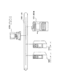
図1は、本発明の実施形態にかかる複写機を用いたネットワークシステムの構成例を示す図である。
複写機1001は複数枚の原稿を読み取り、その画像を記録紙上にプリントするといった通常の複写を行う機能に加え、読み取った原稿画像をネットワークインターフェイスを介してゼロックス社によって開発されたイーサネット等のローカルエリアネットワーク(以下、LAN)1006に接続された他の機器へ送信する機能を有する。
【0021】
Eメール用のメールサーバ1003と各種ファイルを蓄積するファイルサーバ1004は複写機1001から送られたデータ等を格納するコンピュータである。クライアントコンピュータ1005はメールサーバ1003とファイルサーバ1004に接続し、データを取得したり表示したりするコンピュータである。LAN1006は、複写機1001、メールサーバ1003、ファイルサーバ1004、クライアントコンピュータ1005などが接続されるネットワークである。メールサーバ1003は、所謂SMTPサーバ、POPサーバ、ファイルサーバ1004は、所謂FTPサーバやNetWareサーバやSMBサーバなどに相当する。
【0022】
尚、図1においてはファイルサーバ1003、メールサーバ1004及びクライアントコンピュータ1005はそれぞれ1台のみ示したが、それぞれ複数台が同一のネットワークに接続されていてもよい。また、ファイルサーバ1003、メールサーバ1004は同一装置で兼用することもできる。
【0023】
図2は、本実施形態におけるシステムブロック図であり、複写機1001に実装されるコントローラユニット(Controller Unit)の構成を示すものである。Controller Unit2000は画像入力デバイスであるScanner2070や画像出力デバイスであるPrinter2095と接続し、一方ではLAN2011や公衆回線(WAN)2051と接続することで、画像情報やデバイス情報の入出力を行なう為のコントローラである。
【0024】
CPU2001はシステム全体を制御するコントローラである。RAM2002はCPU2001が動作するためのシステムワークメモリであり、画像データを一時記憶するための画像メモリとしても使用される。ROM2003はブートROMであり、システムのブートプログラムが格納されている。HDD2004はハードディスクドライブで、ハードディスクにシステムソフトウェア、画像データ等を格納する。操作部I/F2006はタッチパネルや表示部を有した操作部(UI)2012とのインターフェイス部で、操作部2012に表示する表示用データを操作部2012に対して出力する。また、操作部2012から本システム使用者が入力した情報を、CPU2001に伝える役割をする。Network I/F2010はLAN2011に接続し、情報の入出力を行う。Modem2050は公衆回線2051に接続し、情報の入出力を行う。以上のデバイスがシステムバス2007上に配置される。
【0025】
Image Bus I/F2005はシステムバス2007と画像データを高速で転送する画像バス2008を接続し、データ構造を変換するバスブリッジである。画像バス2008は、例えばPCIバスまたはIEEE1394で構成される。画像バス2008上には以下のデバイスが配置される。ラスターイメージプロセッサ(RIP)2060はPDL(ページ記述言語)コードをビットマップイメージに展開する。デバイスI/F部2020は、画像入出力デバイスであるスキャナ2070やプリンタ2095とコントローラ2000を接続し、画像データの同期系/非同期系の変換を行う。スキャナ画像処理部2080は、スキャナ2070からの入力画像データに対し補正、加工、編集を行う。プリンタ画像処理部2090は、プリンタ2095へ出力されるべきプリント出力画像データに対して、プリンタに応じた補正、解像度変換等を行う。画像回転部2030は画像データの回転を行う。画像圧縮部2040は、多値画像データはJPEG、2値画像データはJBIG方式、MMR符号、MH符号の圧縮伸長処理を行う。
【0026】
スキャナ2070はADF(Auto Document Feeder)から1枚ずつ搬送される原稿もしくはADFを開けて原稿台上に置かれた原稿の画像を光学的に走査して読み取り、電気的な画像データを発生する。プリンタ2095は入力される画像データに基づく画像を記録紙上にプリントする。
【0027】
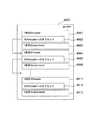
図3は、本実施形態における送信機能を実現するためのソフトウェア構成を示すブロック図であり、これらのソフトウェアはController Unit2000のROM2003及び/又はHDD2004に格納され、CPU2001によって実行される。
【0028】
操作部コンポーネント3001は、操作部2012の制御に関するコンポーネントであり、データを送信するためのプロトコルや送信する画像のフォーマットや送信先などをユーザによる操作部2012のタッチキー操作の指示を検知することにより取得する。
【0029】
送信管理コンポーネント3000は、操作部コンポーネント3001において取得されたデータを送信するためのプロトコルや送信する画像のフォーマットや送信先などの処理命令に従い、スキャナ管理コンポーネント3004により原稿の読み取りを指示し、宛先管理コンポーネント3002より宛先情報を取得し、読込んだ画像データ、あるいはHDD2004に設けられたBox領域から操作部2012による指定で選択された画像データをプリントコンポーネント3005、ファクシミリ送信コンポーネント3006、ファイルサーバ送信コンポーネント3007、メール送信コンポーネント3008、Boxコンポーネント3009に送信処理命令を発行することにより、それぞれ、プリンタ2095、公衆回線2051に接続されたファクシミリ、LAN1006(2011)に接続されたファイルサーバ/メールサーバ、HDD2004に設けられたBox領域に送信、あるいは蓄積することができる。特にファイルサーバ送信コンポーネント3007とメール送信コンポーネント3008は、FTP、NetWare、SMB及びSMTPの4つのプロトコルを用いて、ファイルサーバ/メールサーバ1004に送信することができる。送信管理コンポーネント3000は、宛先管理コンポーネント3002とスキャナ管理コンポーネント3004および各送信コンポーネント間でジョブ制御を行うジョブ管理コンポーネント3003から構成される。
【0030】
<ファイルフォーマット>
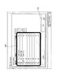
図4は、本実施形態における、M−TIFFフォーマットの概要図であり、このフォーマットはファイルサーバ送信コンポーネント3007内とメール送信コンポーネント3008内の処理で用いられるデータフォーマットである。
【0031】
M−TIFFファイル4000のデータフォーマットの構成は、1枚目の画像データのためのheader4001と1枚目の画像データのdata block4003と2枚目のheader4004と2枚目のdata block4006というように、ヘッダからそのデータブロックが単位となって、その単位が複数並ぶ。例えば、N枚の画像データを構成するフォーマットは、1枚目のdata block4001には、MMR等で圧縮された1枚目の画像が配置され、1枚目のheader4001には、1枚目の画像の解像度や圧縮形式などの属性情報と共に、次のheaderデータの有無を識別するためのオフセット4002が入る。2枚目のdata block4006には、MMR圧縮された2枚目の画像が配置され、2枚目のhearder4004には、2枚目の画像の解像度や圧縮形式などの属性情報と共に、次のheaderデータの有無を識別するためのオフセット4005は入る。このようなフォーマットが最後の画像まで続き、最後の画像であるN枚目のheader内の次のheaderへのオフセットには、「0」が入ることによって、最後の画像であり、ここで1つのファイルとして確定されたことが識別される。
【0032】
図5は、本実施形態における、PDFフォーマットの概要図であり、このフォーマットはファイルサーバ送信コンポーネント3007内とメール送信コンポーネント3008内の処理で用いられるデータフォーマットである。
【0033】
PDFファイル5000のデータフォーマットの構成は、header5001と1枚目のdata5002と2枚目のdata5003・・・・N枚目のdata5009と続き、Pages5010とCross Reference5011とTrailer5012とからなる。header5001は固定的に生成されるTrailer5012はCross Reference5011の位置情報等が入る。1枚目のdata5002は、1枚目の画像データとその解像度や圧縮形式などの属性情報から構成される。2枚目のdata5003も同様に、2枚目の画像データとその解像度や圧縮形式などの属性情報から構成される。1枚目のdata5002や2枚目のdata5003などには、object numberというPDF内でデータを一意に特定するための番号が割り当てられる。Pages5010内にそのobject numberが記述される。Cross Reference5011は、PDF5000内で使われている全てのobject numberとそのobject numberが示すPDF内でのオフセット値が記述される。
図4、図5で示されたファイルフォーマットは図15及び図16のフローチャートにおけるファイルの変換に適用される。
【0034】
<ファイルの送信>
次に、図4、図5に示したようなマルチページファイルを送信する場合の複写機1001の動作について説明する。
図6はこのファイル送信の操作手順を示すフローチャートである。
このフローチャートは、ROM2003及び/又はHDD2004に格納されたプログラムに基づきCPU2001によって制御される処理の流れを示す。
【0035】
先ず、S6001において、操作部2012内のタッチパネル部の基本画面(待機時の図面)である図7の表示において[Send]キーA1にタッチして送信のための種々の指定を行うためのSend画面を呼び出す。
【0036】
続いて、S6002で読取モードを設定するためにSend画面中の[Scan Settings]キーA2を押して図9のScan Settings画面を呼び出す。そしてここで原稿画像を白黒画像として読み取らせるか、カラー画像として読み取らせるかを[Color Mode]キーA4で、また画像の読取解像度を[Resolution]キーA3でそれぞれ指定しこれらを読取モードとして設定する。ここで[OK]キーA5を押してSend画面に戻る。この読取モードは必ずしもここで設定する必要はなく読取指示の前であればいつでも行えるものである。
【0037】
そして、S6003でファイルタイプを設定するためにSend画面の[Send settings]キーA6を押して図10のSend Settings画面を呼び出す。そしてここで送信すべき画像データのファイル形式を指定すべく[File Type]キーA7でリストの中から所望のファイル形式(画像フォーマット)を選択する。ここでは白黒画像の場合、S−TIFF、M−TIFFもしくはPDFが選択でき、カラー画像の場合、JPEGかPDFが選択できる。本実施形態では複数枚の原稿を1つのファイルに変換するフォーマットで送信するので、白黒画像の場合はM−TIFF、PDFを選択し、カラー画像の場合は、PDFを選択したものとする。そしてファイル形式の選択が終了したら[Done]キーA8を押してSend画面に戻る。このファイルタイプの設定も必ずしもここで行う必要はなく読取指示の前であればいつでも行えるものである。
【0038】
そして、S6004において、ファイルを送信するための宛先設定を行うが、既にAddress Book、One-touch Buttons1または2に登録されていれば、その中から選択し、登録されていない場合には、[New Recipient]キーA9を押し、図11の表示に切り替えた後、所望の宛先種別を指定(ここではLAN1006上のファイルサーバ1004内の特定のユーザ用フォルダに蓄積させるべく[File]の指定)する。続いて図12の表示に従って、[Protocol]キーA11でファイルを送信するためのプロトコル、[Host Name]キーA12でファイルサーバ1004のコンピュータ名、[File Path]キーA13でファイルの蓄積先フォルダまでのパス(ディレクトリ)、[User]キーA14でユーザー名、[Password]キーA15でパスワード、をそれぞれ入力する。すべての送信先設定のための入力が終了し[OK]キーA16を押すとSend画面に戻る。
【0039】
ここまでで送信のための諸設定が終了し、これらの設置内容は操作部コンポーネント3001でまとめられ、ジョブ管理コンポーネント3003に通知される。ジョブ管理コンポーネント3003は、これらの情報をまとめて1つのジョブとして扱う。また、操作部コンポーネント3001はこの内容を操作部3012に表示させ、複写機1001のユーザが選択的にキャンセル操作を行えるようにする。
【0040】
ジョブ管理コンポーネント3003はスキャナ管理コンポーネント3004に上記設定の内容を伝え、読取のための設定を行う。そしてS6005で複写機1001のADF(Auto Documents Feeder)に複数(N)枚の原稿がセットされるか、ADFを開けて原稿台上に原稿が置かれた後にS6006で操作部2012内のスタートボタンが押されると上記の設定に従って原稿の走査読取が開始される。ADFにセットされた原稿を読み取る場合は原稿は1枚ずつ搬送されて順次読み取られるが、原稿台上に置かれた原稿を読み取る場合はユーザによって1枚ずつ原稿が交換されるので最後の原稿のときはその旨を指示するための操作が操作部2012で行われる。
【0041】
S6006で読取開始が指示されると、ジョブ管理コンポーネント303は、解像度と白黒読み取りかカラー読み取りかをスキャナ管理コンポーネント3004に指示する。スキャナ管理コンポーネント3004は、デバイスI/F2002を通して、指定された解像度で、指定された白黒読み取り、あるいは、カラー読み取りとして、スキャナ2070を動作させ、複数枚の原稿を順次読込ませ入力画像を得て、スキャナ画像処理部2080で入力画像データを補正、加工、編集する。さらに、画像回転部2030を用いて入力画像を回転し、白黒読み取りの場合は、画像圧縮部2040によってITU−T勧告に従ったtwo-dimensional encoding(以後、MMRと呼ぶ)で圧縮し、複数枚のそれぞれをページ毎のS−TIFFファイルに変換して、HDD2004に格納する。カラー読み取りの場合は、画像圧縮部2040によってJPEG圧縮で圧縮し、複数枚のそれぞれをページ毎のJPEGファイルに変換して、HDD2004に格納する。格納が終了すると、スキャナ管理コンポーネント3004は、ジョブ管理コンポーネント3003に入力された画像のHDD2004内の所在を通知する。
【0042】
次に、ジョブ管理コンポーネント3003は、送信するためのプロトコルがFTPかNetWareかSMBなので、ファイルサーバ送信コンポーネント3007をジョブの処理先として選択し、入力された画像のHDD2004内の所在とフォーマットと送信するためのプロトコルと送信先との情報をファイルサーバ送信コンポーネント3007に通知する。これ以降、S6008でユーザがキャンセルの操作をした場合は、操作部コンポーネント3001が、そのジョブのキャンセルをジョブ管理コンポーネント3003に通知し、ジョブ管理コンポーネント3003が、そのジョブのキャンセルをファイルサーバ送信コンポーネント3007に通知し、S6009で後述のようにキャンセル処理を行う。
【0043】
送信を途中でキャンセルする場合には、図8のSend画面において[System Monitor]キーA18を押して図13のSystem Monitor画面を呼び出す。続いて、ここではSend機能のジョブをキャンセルするので[Send]キーA19を押して、図14のようなSend機能のジョブ状況画面を表示させる。
"Sending"が現在送信処理中で"Waiting"が送信待機中を示す。
【0044】
ここで、今回送信を指示したジョブがA20であるとすると、A20のジョブを押して[Cancel]キーA21を押すことによって送信ジョブA20がキャンセルされる。このとき本当にキャンセルしてもよいかどうかを確認するダイアログを表示し、誤操作を防止するようにしてもよい。
【0045】
ファイルサーバ送信コンポーネント3007は、通知されたプロトコルを読み出し、Network I/F2010を通して用いるプロトコルを決定し、そのプロトコル使って、通知された送信先であるファイルサーバ/メールサーバ1004にアクセスする。通知されたサーバ名とそのサーバ上のユーザ名とパスワードを使って、指定されたファイルサーバ/メールサーバ1004にログインし、送信する画像ファイルを置くディレクトリを指定する。ファイルが生成される日時と指定されたデータフォーマットから送信するファイル名(例えば、日時+データフォーマットに対応した拡張子=20000222.tif)を自動生成し、指定する。
【0046】
ファイルサーバ送信コンポーネント3007は、通知されたフォーマットがM−TIFFだった場合は、HDD2004内に入力された画像はS−TIFFなので、M−TIFFに変換しながら、LAN1006上のファイルサーバ/メールサーバ1004に送信する。これらの処理は送信プロトコルがSMTPの場合、メール送信コンポーネント3008が行う。
【0047】
<ファイルの変換と送信>
次に、上記のようにして原稿上の画像を読み取って得た画像データをM−TIFFに変換し送信する際の処理の流れを図15のフローチャートに基づき説明する。このフローチャートはROM2003及び/又はHDD2004に格納されたプログラムに基づきCPU2001によって制御される処理の流れを示す。
【0048】
図15のステップS15001における、M-TIFFファイルへの変換と送信とが開始されると、まず、S15002において、送信すべき原稿枚数用の変数iを1に初期化する。次に、S15003における原稿の総枚数であるNとiとを比較し、iがNより小さい場合は処理をステップS15004に進める。
【0049】
ステップS15004において、HDD2004内に入力された1枚目の原稿の画像の属性情報を取得し、1枚目のheader4001を作る。次のheaderへのオフセット4002は、1枚目の画像の属性情報内の画像サイズを読み出すことによって算出できる。1枚目のheader4001が生成できた段階で1枚目のheader4001をファイルサーバ/メールサーバ1004に送信する。1枚目のdata block4003とは、HDD2004内に入力された1枚目の画像部のことである。HDD2004内から読み出して、ファイルサーバ/メールサーバ1004に送信し、iに1を加える。次に、S15005における、キャンセルの通知が有るかどうかを調べる。即ち、1枚目のdata blockが全て送信された時に、そのジョブのキャンセル通知がきているかどうかをチェックする。そのジョブのキャンセル通知が来ていない場合は、以下、2枚目以降も同じ操作を繰り返す。M(M<N)枚目のdata blockが全て送信された時にそのジョブのキャンセル通知が来ていた場合は、M枚目のheader内の次のheaderへのオフセットには、M+1枚目のheaderへのオフセット値が入ってしまっている。このため、S6006において、M+1枚目のheader内の次のheaderへのオフセットに「0」を代入して、M+1枚目のheaderを生成し送信して、M+1枚目のdata blockを送信して、そのジョブの送信を終了する。
【0050】
また、ファイルサーバ送信コンポーネント3007は、通知されたフォーマットがPDFだった場合は、HDD2004内に入力された画像はS−TIFFかJPEGなので、PDFに変換しながら、ファイルサーバ/メールサーバ1004に送信する必要がある。図16は、本実施形態におけるPDFファイルへの変換と送信との流れを示すフローチャートである。このフローチャートはROM2003及び/又はHDD2004に格納されたプログラムに基づきCPU2001によって制御される処理の流れを示す。ステップS16001において、PDFファイルへの変換と送信とを開始する。
【0051】
先ず、ステップS16002で、header5001を生成し、ファイルサーバ/メールサーバ1004に送信し、送信すべき原稿枚数用の変数iを1に初期化する。次に、ステップS16003における、原稿の総枚数であるNと原稿枚数をカウントするための変数iとを比較し、iがNより小さい場合は、処理をステップS16004に進める。ステップS16004において、HDD2004内に入力された1枚目の画像と画像の属性情報を読み出し、1枚目のdata5002を作り送信し、原稿枚数をカウントするための変数iに1を加える。
【0052】
次に、処理をステップS16005における、キャンセルの通知があるかどうかを調べる。キャンセルの通知がなければ、以下、2枚目以降も同じ操作を繰り返す。
M(M<N)枚目のdataが送信された時のそのジョブのキャンセル通知が来ていた場合は、S16006における、M枚目までのobject noを記述したPages5010を生成して送信し、PDF5000内で使われている全てのobject noとそのobject noが示すPDF内でのオフセット値を記述したCross Reference5011を生成して送信し、Trailer5012を生成して送信して、そのジョブの送信を終了する。
【0053】
以上の実施形態では、ユーザの指示によりジョブがキャンセルされた場合について説明したが、装置のエラー等によってユーザが介在せずにキャンセルされた場合も同様である。
【0054】
以上、本実施形態によれば、画像データの送信の中断を送信中に指示した場合、中断の指示を受付け、中断までに送信した画像データを一つの画像データのまとまりとして再変換して、データの送信を完了させることにより、異常ファイルを作りださずに、ユーザにとって使い勝っての良い円滑な画像処理を可能とする。
【0055】
(第2の実施形態)
上述の第1の実施形態は複数枚の原稿を各ページ毎に属性情報を有した1つのファイルとして送信させる場合に、途中でキャンセルされても送信できたところまでは受け側で正常なファイルとして扱えるようファイルを確定させるものである。これによって不完全な状態の異常ファイルを送信することによって無駄なメモリ領域を使用してしまうことを防ぐとともに送信をやり直す場合は続きから行えるものであった。
【0056】
以下に示す第2の実施形態は、例えば複写機1001のRAM2002等に設定されたSend機能のためのワークエリアに上限がある場合、PDFでの送信時のCross Reference5011では、送信する画像データとその属性情報等とを格納した場所のオフセット値をそのobject noと共に記載する必要があり、PDFに変換して送信できる画像枚数が制限されてしまう。これを防ぐために、上記のワークエリアの許容範囲でCross Reference5011を作成し送信し、Trailer5012を送信して、一つのPDFファイルとして完結させた後に、headerや続きの画像データ等をそのPDFファイルに追加して書込み、その追加した画像データ等に関するCross ReferenceやTrailerも含めたもう一つのPDFファイルを追加して、この二つのPDFファイルを連結するという表現を加えることによって、一つのPDFファイルとして表現できるようにし、PDFに変換して送信できる画像枚数が制限されないようにしたものである。
【0057】
以下、その処理について詳細に説明する。
システム構成、複写機1001の構成は図1〜図3に示した通りであるので、ここでの説明は省略する。
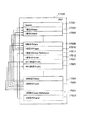
図17は、本実施形態における、PDFファイルのデータフォーマット概要を説明する図である。本実施形態において、スキャンした画像を1つのPDFファイルに変換できる上限枚数はMとし、図17では送信すべき画像の総数は2Mであった場合のデータフォーマットを示している。
【0058】
スキャンした画像データから図17に示すようなPDFファイルを作成するのはファイルサーバ送信コンポーネント3007(もしくはメール送信コンポーネント3008)である。PDFファイル17000は、header17001と1枚目のdata17002、2枚目のdata17003、...と上限数であるM枚目のdata17009までdataが連続する。そしてM枚目のdata17009の次に一回目のPages17010、一回目のCross Reference17011及び一回目のTrailer17012が連続した後、M+1枚目のdata17022、M+2枚目のdata17023、...、2M枚目のdata17029とdataが連続する。2M枚目のdata17029の後ろには、M枚目のdata17009の後ろと同様、二回目のPages17030、二回目のCross Reference17031及び二回目のTrailer17032が連続する。
【0059】
このうち、header17001は、固定的に生成できる。1枚目のdata17002は、1枚目の原稿画像とその解像度や圧縮形式などの属性情報から構成される。2枚目のdata17003も、2枚目の画像とその解像度や圧縮形式などの属性情報から構成される。同じようにdataが続き、M枚目のdata17009も、M枚目の画像とその解像度や圧縮形式などの属性情報から構成される。1枚目のdata17002や2枚目のdata17003などには、object noというPDFファイル17000内で一意の番号が割り当てられる。
【0060】
一回目のPages17010内にそれらのobject noが記述される。一回目のCross Reference17011は、一回目のCross Reference17011までに現れた全てのobject noとそのobject noが示すPDF内での位置情報が記述される。一回目のTrailer17012には、一回目のCross Reference17011の位置情報が記述される。
【0061】
次に、M+1枚目のdata17022は、M+1枚目の画像とその解像度や圧縮形式などの属性情報から構成される。M+2枚目のdata17023も、M+2枚目の画像とその解像度や圧縮形式などの属性情報から構成される。同じようにdataが続き、2M枚目のdata17029も、2M枚目の画像とその解像度や圧縮形式などの属性情報から構成される。M+1枚目のdata17022やM+2枚目のdata17023などにも、object noというPDFファイル17000内で一位の番号が割り当てられる。
【0062】
二回目のPages17030内には、1枚目の画像のdata17001から2枚目の画像data17029までのobject noが記述される。二回目のCross Reference17031には、一回目のPages17010を二日目のPages17030で更新すること、二回目のPages17030の位置情報、M+1枚目のdata17022のobject no、及び、M+1枚目のdata17022から二枚目のCross Reference17031までに現れた全てのobjectの位置情報の値が順に記述される。
【0063】
二回目のTrailer17032には一回目のCross Reference17011の位置情報と二回目のCross Reference17031の位置情報とが記述される。これによって、このファイルを受けた側では一回のPages、Cross Reference、Trailerが反映されたものがそれぞれ二回目のものに加えられ、一回目のものが削除され、1つのPDFファイルを形成可能となる。ここで、完全なPDFファイルには他の要素も含まれるが、本実施形態とは直接関係ないので図17での図示及びその説明は省略する。
【0064】
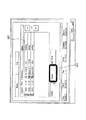
図18は、図17における二回目のPages17030の具体的な記述例を示す図である。図18においては、スキャンした画像の変換できる上限数Mは200、スキャンした画像の総数2Mが400である場合を示している。"/Kids"の行18001で、1枚目の画像のdata17001から2枚目の画像のdata17029までのobject noが記述されている。1枚目の画像のdata17001のobject noは、"1 0 R"であり、2M枚目の画像のdata17029のobject noは、"2394 0 R"である。"/Count 400"は、全ての画像のdataのobject数を示しており、その値は2Mであるから、400となる。
【0065】
図19は、図17における二回目のCross Reference17031の具体的な記述例を示す図である。図18と同様、スキャンした画像の変換できる上限数Mは200とし、スキャンした画像の総数2Mが400である場合を示している。一回目のPages17010を二回目のPages17030で更新することを示す"2 1"が行19001に記述され、次いで二回目のPagesの位置情報が行19002に、M+1行目のdata17022のobject no(1200)が行19003に、M+1枚目のdata17022の位置情報が行19004にそれぞれ記述され、以下、二回目のCross Reference17031までに現れた全てのobjectの位置情報の値が記述される。
【0066】
図20は、図17における二回目のTrailer17032の具体的な記述例を示す図である。図20においても、スキャンした画像の変換できる上限数Mは200とし、スキャンした画像の総数2Mが400である場合を示している。二回目のTrailer17032には、直前(一回目)のCross Reference17011の位置情報が行20001に、二回目のCross Reference17031の位置情報が行20002にそれぞれ記述される。
【0067】
以下、本実施形態に係る複写機において、第2の実施形態におる送信処理を実行する際の流れを順に説明する。
図21は第2の実施形態による複写機1001の操作手順の流れを示すフローチャートである。このフローチャートはROM2003及び/又はHDD2004に格納されたプログラムに基づきCPU2001によって制御される処理の流れを示す。
【0068】
S21001〜S21006の処理については前述の図6のS6001〜S6006と同様であるのでここでの詳細な説明は省略する。
ただし、S21003のファイルタイプ設定ではPDFファイルを指定する。またS21005及びS21006ではADFに原稿をセットする場合も原稿台に原稿を置く場合も最後の原稿(ADFの場合は最後の原稿の束)であることを指定するまでは一連の原稿(共通のファイルとされるべき原稿)として扱われる。
【0069】
S21007ではS21001〜S21004で設定された内容に基づき原稿上の画像の読み取りと後述するような手順での送信処理を開始する。そして、S21008で最終原稿と判断されるまで処理を継続する。
S21009で送信終了と判断されたら一連の送信処理を終了する。
【0070】
次に、図17に示すデータ構成及び図22に示すフローチャートを用いて、PDFファイルの生成及び送信にかかる一連の処理を説明する。図22においては、一回で変換できる画像の上限ページ数はMとし、送信されるべき一連の画像の総ページ数はN(N>M)であった場合の例を示す。
【0071】
ファイルサーバ送信コンポーネント3007は、ステップS22001において、PDFファイルの生成、送信処理が開始されると、まずステップS22002において、header17001を生成、送信し、送信した画像数用の変数iを0に初期化する。
次に、ステップS22003において、変換した画像数用の変数jを0に初期化する。
【0072】
次に、ステップS22004において、原稿の総枚数であるNとiとを比較し、iがNより小さければステップS22005に進み、iがN以上、すなわち全部の画像が送信された場合にはステップS22008に進む。
次にステップS22005において、画像を一度に変換できる上限数であるMとjを比較し、jがMより小さければステップS22006に進み、jがM以上、即ち上限に達した場合にはステップS22007に進む。
【0073】
次にステップS22006において、i枚目の原稿画像の属性情報とデータを取得し、dataを生成し、送信し、iとjに1を加えて、ステップS22004に戻る。
M枚目までの送信が終了すると、ステップS22007において、1枚目のdata17002のobject noからi枚目のdata17009までのobject noを一回目のPages17010に書き込み、それらの位置情報を一回目のCross Reference17011に書き込み、一回目のTrailer17012を生成して送信し、ステップS22003に戻る。
【0074】
ステップS22007での処理が一回目の場合は、生成したCross Referenceの位置情報を記憶しておく。n(nは2以上の自然数)回目以降の処理では、n回目のPagesに、1枚目の画像のdataから(n×M)枚目の画像のdataまでのobject noが記述される。そして、n回目のCross Referenceに、(n−1)回目のPagesをn回目のPagesで更新すること、n回目のPagesの位置情報、((n−1)×M+1)枚目のdataのobject no及び、((n−1)×M+1)枚目からi枚目のdataまでに現れた全てのobjectの位置情報の値が順に記述される。そして、n回目のTrailerの生成時に、前回のCross Referenceの位置情報を書き込み、かつ、今回生成したCross Referenceの位置情報を記憶しておく。
【0075】
N枚目までの送信が終了すると、ステップS22008において、1枚目のdataのobject noからN枚目までのdataのobject noをPagesに書き込み、前回のPagesを今回生成したPagesで更新すること、今回生成したPagesの位置情報、(N−j)枚目のdataのobject no及び(N−j)枚目のdataから今回生成したCross Referenceまでに現れた全てのobjectの位置情報をCross Referenceに書き込み、前回のCross Referenceの位置情報と、今回のCross Referenceの位置情報を書き込んだTrailerを生成して送信し、ステップS22009に進む。
【0076】
ステップS22009において、PDFファイルへの変換と送信処理とを終了する。
以上の実施形態では分割の基準として上限ページ数を用いたが、これに限ることなく画像データのデータ量(Mバイト)等としてもよい。
【0077】
上述の実施形態においては、PDF形式のファイルを生成する場合を例にして説明したが、複数の画像データを1ファイルにまとめるデータフォーマットのファイルを生成する場合であって、同様の問題点を有する場合には本発明を適用することが可能である。
この場合も、ファイルが生成できる原稿画像の量に応じた複数のファイルブロックを形成し、各ブロック間の関連を示す情報を付加して送信するとともに、受信側でこの付加情報を元に一連のファイルとして取り扱うように構成すればよい。
【0078】
上述の実施形態においては二番目以降のファイルブロックに直前のファイルブロックを特定可能な情報を付加したが、次に続くファイルブロックを特定可能な情報を付加するように構成することも可能である。
また、上述の第2の実施形態によれば、二回目(最後)のCross Referenceに直前のファイルブロックのPagesの情報を今回のPagesで更新することを表す上表が書き込まれているので、このファイルを受けた側では途中のCross ReferenceやPagesを削除することができ、最終的に形成されるファイルのサイズを小さくかつシンプルにすることができる。
【0079】
また、分割されたファイルのそれぞれがページ単位で区切られCross ReferenceやPagesを有しているので分割されたファイル(それぞれがマルチページで構成されたファイル)は、それら自体がファイルとして確定されているので、受け側のアプリケーションによっては上記のように最後のCross Reference、Pagesには他の分割ファイルの情報を書き込まず、そしてそれぞれのファイルのCross ReferenceやPagesを削除しないようにすれば、それぞれ独立したファイルとして扱えるようにでき、大きなファイルを扱えない環境でもそれぞれのフィルを適切に処理できるようになる。
【0080】
(第3の実施形態)
これまで述べた実施形態はオフセット値やCross Reference、Pages、Trailer等を制御することによって途中で処理を終了したファイルをその時点で確定させたり、大量の画像データを分割して送信するものであった。
以下に述べる第3の実施形態はこのオフセット値等を制御する技術を用いて任意の複数の画像データを選択してそれらを結合し1つのファイルに再変換して送信するものである。
【0081】
以下にその手順について詳細に説明する。
図23は第3の実施形態による複写機1001の操作手順の流れを示すフローチャートである。このフローチャートはROM2003及び/又はHDD2004に格納されたプログラムに基づきCPU2001によって制御される処理の流れを示す。
【0082】
S23001及びS23002では上述のものと同様に読取モードの設定を行う。
そして、S23003でBox指定を行うために、図10のSend Setting画面で[Store In Box]キーA22を押し、図24のようなStore In Box画面を呼び出す。
【0083】
複写機1001ではHDD2004を種々の画像データを蓄積できるように複数に分割しており、分割された個々の蓄積先をBoxと呼び、それらはBox番号で区分されている。ここではBox番号00のA23が選択されたものとする。そして[OK]キーA24が押されると蓄積先が設定され、Send Setting画面に戻る。続いて[Done]キーA8を押してSend画面に戻る。
【0084】
そして、S23004でADFまたは原稿台に原稿があることを確認して、S23005で操作部2012のスタートボタンが押されると設定された内容に基づき原稿上の画像の読み取りを開始し、S23006でBox00に読取画像データが白黒画像ならS−TIFF、カラー画像ならJPEGで蓄積される。このとき読み取りをカラーで行ったか白黒で行ったか、画像サイズ、枚数、蓄積日時も一緒にそれぞれ対応付けて蓄積する。蓄積が終了すると、スキャナ管理コンポーネント3004は蓄積された画像のHDD2004内の所在をジョブ管理コンポーネント3003に通知する。ジョブ管理コンポーネント3003は、HDD2004内の蓄積された画像の所在とBox番号をBoxコンポーネント3009に通知する。Boxコンポーネント3009は、HDD2004内の蓄積された画像の所在とBox番号との関係をHDD2004内に記憶しておく。以上の操作が何回か繰り返されると、Boxコンポーネント3009には、種々の時点で複数の画像データが蓄積された種々の画像データに関する情報が、Box番号とともに多数記憶される。なお、ここで蓄積される画像はスキャナ2070からの画像に限らずネットワークI/F2010やモデム2050など、種々の入力源からの画像としてもよい。
ここまでの処理はどの時点に行っても良い。
【0085】
S23006ではBox内の所望の画像データを選択するために図7の基本画面において[Mail Box]キーA25を押し、図25のMail Box画面を呼び出す。ここではBox00に格納されている複数の画像データを選択するものとし、Mail Box画面でBox00の中身を表示させるべくA26を押す。そしてユーザは図26のBox No00の中身の確認画面(操作部コンポーネント3001に問い合わせることにより得た情報に基づき表示される)において、画像サイズや蓄積日付等を参照して結合して送信したい画像データとしてA27、A28、A29の3つをこの順序で選択する。すると操作部コンポーネント3001は選択された画像データをその順番とともに記憶し、この選択した順序が左端に表示される(1〜3)。
【0086】
次にS23008で、送信設定を行うために[Send]キーA30を押し、図27のSending Address Setting画面を呼び出す。そしてここではAddress Bookから予め登録されている宛先に送信するものとして、[Address Book]キーA31を押す。すると図28のAddress Book画面が表示されるのでここではE-mailでmarc@ganon.com、インターネットFAXでmatt@ganon.comに送信することが選択するものとして、ユーザはA32とA33を押す。この選択により、E-mailアドレスの他に送信プロトコル(SMTP)とその送信に必要な情報(SMTPサーバーにアクセスするためのユーザ名、パスワード)が設定される。送信プロトコルとしてFTPが選択された場合は宛先情報にサーバ名とそのサーバ上のユーザ名とパスワードとディレクトリ名とになり、ログイン処理後に蓄積処理が実行される。
【0087】
A32とA33が選択された後、[OK]キーA34が押されるとこれらの宛先が設定され、Sending Address Setting画面に戻り、図29のようにここで設定された宛先が入力された状態となる。
【0088】
そして、S23009で前述のようにファイルタイプの設定が行われ、S23010で操作部2102のスタートボタンが押されると、S23011で後述するような処理手順で先に選択した3つの画像データがその順序で結合され1つのファイルとして送信される。
【0089】
送信時の画像フォーマットとしては、白黒画像の場合、S−TIFFかM−TIFFかPDFかが選択でき、カラー画像あるいは白黒画像とカラー画像の混合の場合は、JPEGかPDFかが選択できる。ただし、上述の画像データを1ファイルにまとめられるデータフォーマットは、白黒画像のみの場合、M−TIFFかPDF、カラー画像のみ、あるいは白黒画像とカラー画像の混合の場合は、PDFとなるので、以下の説明においてはこれら複数枚の原稿の画像を1つのファイルに変換するデータフォーマットが選択されたものとする。
【0090】
なお、送信開始のタイミングは送信プロトコルに応じて切り替えられるべきであり、ファイルの生成と送信とを並行して行える場合には、そのようにし、それが行えない場合にはファイル確定後に送信を開始するようにする。
S23012で送信終了と判断されたら一連の送信処理を終了する。
【0091】
以下、図30、図31のフローチャートではファイルフォーマットとして図4、図5に示したものを参照する。
また、図30、図31のフローチャートはROM2003及び/又はHDD2004に格納されたプログラムに基づきCPU2001が制御する処理の流れを示す。
【0092】
図30は、本実施形態にかかる複写機で実施される、複数の画像データを結合して1ファイルとして送信する処理を示すフローチャートである。図30に示す処理は、画像データの送信先に応じてファイルサーバ送信コンポーネント3007又はメール送信コンポーネント3008によって実行される。以下の説明において、ユーザが選択した送信画像データの数はN(2以上の自然数)とする。
【0093】
ステップS30001において、M−TIFFファイルへの変換と送信とが開始されると、先ずステップS30002において、送信する画像枚数用の変数iを1に初期化する。次にステップS30003において、送信すべき画像の総枚数であるNとiとを比較し、iがNより小さければ、ステップS30004に進み、iがN以上であれば、ステップS30006に進む。
【0094】
ステップS30004において、i枚目の原稿の画像の属性情報を、その画像が蓄積されたBoxから取得し、そのデータサイズから次のheaderへのオフセット値を求め、headerを生成、送信する。同時に、蓄積画像データを読み出し、送信を行う。送信が終了したら変数iに1を加え、ステップS30003に戻る。
【0095】
変数iがNになったら、ステップS30006において、ステップS30004と同様の送信処理を行い、変換、送信処理を終了する。この際、上述したようにN枚目のheader4011に含まれる次の次のheaderへのオフセット値には0を格納する。
【0096】
図31は、本実施形態にかかる複写機で実施される、S−TIFFやJPEGファイルからPDFファイルへの変換及び信号処理を示すフローチャートである。図31に示す処理は、画像データの送信先に応じてファイルサーバ送信コンポーネント3007又はメール送信コンポーネント3008によって実行される。以下の説明において、ユーザが選択した送信画像データの数はN(2以上の自然数)とする。
【0097】
先ず、ステップS31001において、PDFファイルへの変換と送信とが開始されると、ステップS31002において、headerを生成して送信し、送信する画像枚数用の変数iを1に初期化する。
【0098】
次にステップS31003において、送信すべき画像の総枚数であるNとiとを比較し、iがNより小さければ、ステップS31004に進み、iがN以上であれば、ステップS31006に進む。ステップS31004において、i枚目の画像データが格納されているBoxから、その属性情報とデータを取得し、dataを生成し送信し、iに1を加え、ステップS31003に戻る。
【0099】
変数iがNになると、ステップS31006において、1枚目からN枚目までのobject noをPages5010に書き込み、それらのオフセット値をCross Reference5011に書き込み、Trailer5012を生成して送信する。
【0100】
上述の実施形態においては、一旦S−TIFFやJPEG等のデータフォーマットで蓄積した画像データを、送信時にM−TIFFやPDF形式に変換する構成のみを示したが、画像を読み取って蓄積する段階で、複数の原稿がある場合には、M−TIFFやPDF形式のファイルに変換しておき、送信の際には変換をしないように構成することもできる。
【0101】
また、クライアントコンピュータ1005に複写機1001の操作部2012をリモート制御する機能を持たせ、複写機1001の操作部2012を用いて選択もしくは入力可能な指示をクライアントコンピュータ1005からユーザが指示するように構成することも可能である。
【0102】
また、画像データの蓄積時に行う符号化形式や、蓄積された画像データの複数を1つのファイルにまとめるデータフォーマットについては、上述の実施形態で挙げたものに限定されず、任意の形式を用いることができる。
【0103】
なお、本発明は、複数の機器(例えばホストコンピュータ、インターフェイス機器、リーダ、プリンタなど)から構成されるシステムに適用しても、一つの機器からなる装置(例えば、複写機、ファクシミリ装置など)に適用してもよい。
【0104】
また、本発明の目的は、前述した実施形態の機能を実現するソフトウェアのプログラムコードを記録した記憶媒体(または記録媒体)を、システムあるいは装置に供給し、そのシステムあるいは装置のコンピュータ(またはCPUやMPU)が記憶媒体に格納されたプログラムコードを読み出し実行することによっても、達成されることは言うまでもない。この場合、記録媒体から読み出されたプログラムコード自体が前述した実施形態の機能を実現することになりそのプログラムコードを記憶した記憶媒体は本発明を構成することになる。また、コンピュータが読み出したプログラムコードを実行することにより、前述した実施形態の機能が実現されるだけでなく、そのプログラムコードの指示に基づき、コンピュータ上で稼動しているオペレーティングシステム(OS)などが実際の処理の一部または全部を行い、その処理によって前述した実施形態の機能が実現される場合も含まれることは言うまでもない。
【0105】
さらに、記憶媒体から読み出されたプログラムコードが、コンピュータに挿入された機能拡張カードやコンピュータに接続された機能拡張ユニットに備わるメモリに書き込まれた後、そのプログラムコードの指示に基づき、その機能拡張カードや機能拡張ユニットに備わるCPUなどが実際の処理の一部または全部を行い、その処理によって前述した実施形態の機能が実現される場合も含まれることは言うまでもない。
【0106】
本発明を上記記憶媒体に適用する場合、その記憶媒体には、先に説明したフローチャートに対応するプログラムコードが格納されることになる。
【0107】
【発明の効果】
以上説明したように、本発明によれば、柔軟性に富んだファイル操作が可能なデータ処理装置及びデータ処理方法が実現できる。
【図面の簡単な説明】
【図1】本発明の実施形態にかかる複写機を接続したシステムの構成を示す図である。
【図2】本発明の実施形態にかかる複写機の概略構成を示すブロック図である。
【図3】本発明の実施形態にかかる複写機の動作を制御するソフトウェア構成を示すブロック図である。
【図4】M−TIFFファイルのフォーマットを示す図である。
【図5】PDFファイルのフォーマットを示す図である。
【図6】第1の実施形態による処理手順を示すフローチャートである。
【図7】操作部2012のタッチパネル部に表示される基本画面例を示す図である。
【図8】操作部2012のタッチパネル部に表示されるSend画面例を示す図である。
【図9】操作部2012のタッチパネル部に表示されるScan Settings画面例を示す図である。
【図10】操作部2012のタッチパネル部に表示されるSend Settings画面例を示す図である。
【図11】操作部2012のタッチパネル部に表示されるSend Settings画面例を示す図である。
【図12】、操作部2012のタッチパネル部に表示される宛先入力画面例を示す図である。
【図13】操作部2012のタッチパネル部に表示されるSystem Monitor画面例を示す図である。
【図14】操作部2012のタッチパネル部に表示されるジョブ状況画面例を示す図である。
【図15】第1の実施形態において、原稿上の画像を読み取って得た画像データをM−TIFFに変換し送信する際の処理を説明するフローチャートである。
【図16】第1の実施形態におけるPDFファイルへの変換と送信処理を説明するフローチャートである。
【図17】第2の実施形態における、PDFファイルのデータフォーマット概要を説明する図である。
【図18】図17のフォーマットにおける二回目のPages17030の具体的な記述例を示す図である。
【図19】図17のフォーマットにおける二回目のCross Reference17031の具体的な記述例を示す図である。
【図20】図17のフォーマットにおける二回目のTrailer17032の具体的な記述例を示す図である。
【図21】第2の実施形態による複写機1001の操作手順の流れを示すフローチャートである。
【図22】第2の実施形態におけるPDFファイルの生成及び送信処理を説明するフローチャートである。
【図23】第3の実施形態による複写機1001の操作手順の流れを示すフローチャートである。
【図24】操作部2012のタッチパネル部に表示されるStore In Box画面例を示す図である。
【図25】操作部2012のタッチパネル部に表示されるMail Box画面例を示す図である。
【図26】操作部2012のタッチパネル部に表示されるMail Boxの中身の確認画面例を示す図である。
【図27】操作部2012のタッチパネル部に表示されるSending Address Setting画面例を示す図である。
【図28】操作部2012のタッチパネル部に表示されるAddress Book画面例を示す図である。
【図29】操作部2012のタッチパネル部に表示されるAddress Book画面例を示す図である。
【図30】第3の実施形態にかかる複写機のファイル結合、送信処理を説明するフローチャートである。
【図31】第3の実施形態にかかる複写機における、ファイル形式変換処理及び信号処理を説明するフローチャートである。[0001]
BACKGROUND OF THE INVENTION
The present invention can form an image file as a single file with a plurality of pages from input image data.dataProcessing equipment andData processingIt is about the method.
[0002]
[Prior art]
In recent years, it has been proposed to connect an image scanner to a computer network, scan the original with the scanner, read the image on the original, and send the image data as an image file to the computer network.
In transmission of image data in such an image scanner, the user selects a transmission protocol, resolution of an image to be transmitted, monochrome or color, a format, and a transmission destination from the operation unit.
[0003]
Transmission protocols include Simple Mail Transfer Protocol (hereinafter referred to as SMTP), File Transfer Protocol (hereinafter referred to as FTP), and NetWare and Server Message Block Protocol (hereinafter referred to as SMB) developed by Novell. and so on.
[0004]
The resolution of an image has a main scanning direction and a sub-scanning direction, and the unit is expressed by, for example, dot per inch (hereinafter referred to as dpi). That is, if 200
[0005]
When acquiring a monochrome image by scanning, the image format is, for example, Single Page Tag Image File Format (hereinafter referred to as S-TIFF), Multiple Page Tag Image File Format (hereinafter referred to as M-TIFF) or Designate Portable Document Format (hereinafter referred to as PDF) developed by Adobe.
[0006]
When acquiring a color image by scanning, for example, a Joint Photographic Experts Group Format (hereinafter referred to as JPEG), PDF, or the like is designated. S-TIFF and JPEG are formats in which an image of one page of a document is made into one file, and M-TIFF and PDF are formats in which images of a plurality of documents are made into one file.
[0007]
The expression of the transmission destination is different for each transmission protocol. The SMTP transmission destination is an e-mail destination, and the FTP, NetWare, or SMB transmission destination is a server name, a user name on the server, a password, and a directory name. Furthermore, a file name to be transmitted can be added.
[0008]
[Problems to be solved by the invention]
In such an image scanner, when one file is formed with a plurality of pages, such as M-TIFF or PDF, for example, when an image memory shortage occurs or a user gives an interruption instruction, The processing was terminated when the image file created for the image of the original read incompletely was incomplete, and the image file could not be used.
[0009]
This is because in M-TIFF or FDF, an offset value or the like is written after each page and information for establishing a file is written after the last page in order to display an arbitrary page. However, if the processing is terminated halfway, such information cannot be written, resulting in an incomplete file, which cannot be processed by an application compatible with M-TIFF or PDF. It ends up.
[0010]
The object of the present invention is to eliminate the above-mentioned problems., Data processing apparatus and data processing method capable of flexible file operationIs to provide.
[0011]
[Means for Solving the Problems]
That is, the gist of the present invention is an input unit that inputs data in units of pages, information that has a plurality of pages based on the data input by the input unit, and indicates the presence of the next page in association with each page or Generating means for generating one file including information indicating the final page, and generation of the file by the generating meansCancelAn instruction means for instructingWhen a cancellation instruction is given by the instruction means, the next generation page by the generation meansInformation indicating the last pageMatchWrite to the fileGeneration meansAnd a control means for controlling the data processing apparatus.
[0014]
Another gist of the present invention is as follows.By input meansAn input process for entering data in page units;By generating means,A generation step for generating a single file including information indicating the presence of the next page or information indicating the presence of the next page in association with each page based on the data input in the input step; ,By instruction meansFile generation by the generation processCancelAn instruction process for instructing;When a stop instruction is issued by the instruction process, the control means displays the next page generated by the generation process,Information indicating the last pageMatchWrite to the fileGeneration processAnd a control process for controlling the data processing method.
[0020]
DETAILED DESCRIPTION OF THE INVENTION
(First embodiment)
Hereinafter, the present invention will be described in detail based on the embodiments with reference to the drawings.
FIG. 1 is a diagram showing a configuration example of a network system using a copying machine according to an embodiment of the present invention.
The copying machine 1001 reads a plurality of originals and prints the images on a recording sheet. In addition to a function of performing normal copying, a local area such as an Ethernet developed by Xerox Co., Ltd. via the network interface. It has a function of transmitting to other devices connected to a network (hereinafter, LAN) 1006.
[0021]
A
[0022]
Although only one
[0023]
FIG. 2 is a system block diagram according to this embodiment, and shows a configuration of a controller unit (Controller Unit) mounted on the copying machine 1001. The Controller Unit 2000 is connected to a
[0024]
A
[0025]
An image bus I /
[0026]
The
[0027]
FIG. 3 is a block diagram showing a software configuration for realizing the transmission function in the present embodiment. These software are stored in the
[0028]
The
[0029]
The
[0030]
<File format>
FIG. 4 is a schematic diagram of the M-TIFF format in the present embodiment, and this format is a data format used in processing in the file
[0031]
The data format of the M-
[0032]
FIG. 5 is a schematic diagram of the PDF format in this embodiment, and this format is a data format used in processing in the file
[0033]
The data format of the
The file format shown in FIGS. 4 and 5 is applied to the file conversion in the flowcharts of FIGS. 15 and 16.
[0034]
<Send file>
Next, the operation of the copying machine 1001 when transmitting a multi-page file as shown in FIGS. 4 and 5 will be described.
FIG. 6 is a flowchart showing the file transmission operation procedure.
This flowchart shows a flow of processing controlled by the
[0035]
First, in S6001, a Send screen for making various designations for transmission by touching the [Send] key A1 in the display of FIG. 7 which is a basic screen (drawing in standby) of the touch panel in the
[0036]
Subsequently, in step S6002, in order to set the reading mode, the [Scan Settings] key A2 in the Send screen is pressed to call the Scan Settings screen in FIG. Here, whether the original image is read as a monochrome image or a color image is designated by the [Color Mode] key A4, and the reading resolution of the image is designated by the [Resolution] key A3, and these are set as the reading mode. . Here, press the [OK] key A5 to return to the Send screen. This reading mode does not necessarily need to be set here, and can be performed at any time before a reading instruction.
[0037]
In step S6003, the [Send settings] key A6 on the Send screen is pressed to call the Send Settings screen in FIG. 10 in order to set the file type. In order to designate the file format of the image data to be transmitted here, a desired file format (image format) is selected from the list with the [File Type] key A7. Here, S-TIFF, M-TIFF or PDF can be selected for a monochrome image, and JPEG or PDF can be selected for a color image. In this embodiment, since a plurality of documents are transmitted in a format that converts them into one file, it is assumed that M-TIFF and PDF are selected for a monochrome image, and PDF is selected for a color image. When the file format is selected, the [Done] key A8 is pressed to return to the Send screen. This file type setting is not necessarily performed here, and can be performed any time before the reading instruction.
[0038]
In step S6004, the destination for sending the file is set. If it is already registered in Address Book, One-
[0039]
Up to this point, various settings for transmission are completed, and these installation contents are collected by the
[0040]
The
[0041]
When the start of reading is instructed in step S6006, the job management component 303 instructs the
[0042]
Next, since the transmission protocol is FTP, NetWare, or SMB, the
[0043]
When canceling transmission in the middle, the [System Monitor] key A18 is pressed on the Send screen in FIG. 8 to call the System Monitor screen in FIG. Subsequently, since the job of the Send function is canceled here, the [Send] key A19 is pressed to display the job status screen of the Send function as shown in FIG.
“Sending” indicates that transmission processing is currently in progress, and “Waiting” indicates that transmission is waiting.
[0044]
Here, if the job instructed to be transmitted is A20, the transmission job A20 is canceled by pressing the job A20 and pressing the [Cancel] key A21. At this time, a dialog for confirming whether or not to cancel can be displayed to prevent erroneous operation.
[0045]
The file
[0046]
When the notified format is M-TIFF, the file
[0047]
<File conversion and transmission>
Next, the flow of processing when the image data obtained by reading the image on the document as described above is converted into M-TIFF and transmitted will be described with reference to the flowchart of FIG. This flowchart shows the flow of processing controlled by the
[0048]
When conversion to an M-TIFF file and transmission in step S15001 in FIG. 15 are started, first, a variable i for the number of documents to be transmitted is initialized to 1 in S15002. Next, the total number of documents in S15003 is compared with i and if i is smaller than N, the process advances to step S15004.
[0049]
In step S15004, the attribute information of the image of the first document input in the
[0050]
In addition, when the notified format is PDF, the file
[0051]
First, in
[0052]
Next, it is checked whether or not there is a cancellation notification in step S16005. If there is no cancellation notification, the same operation is repeated for the second and subsequent sheets.
If the job cancellation notification is received when the M (M <N) th data is transmitted,
[0053]
In the above embodiment, the case where the job is canceled by the user's instruction has been described, but the same applies to the case where the user is canceled without the intervention of an apparatus error or the like.
[0054]
As described above, according to the present embodiment, when an interruption of transmission of image data is instructed during transmission, the interruption instruction is accepted, and the image data transmitted up to the interruption is reconverted as a set of image data, and the data By completing the transmission, smooth image processing that is convenient for the user can be performed without creating an abnormal file.
[0055]
(Second Embodiment)
In the first embodiment described above, when a plurality of originals are transmitted as a single file having attribute information for each page, even if the transmission is canceled in the middle, the file can be transmitted as a normal file on the receiving side. The file is fixed so that it can be handled. This prevents the use of a useless memory area by transmitting an abnormal file in an incomplete state, and re-transmission can be continued.
[0056]
In the second embodiment described below, for example, when there is an upper limit in the work area for the Send function set in the
[0057]
Hereinafter, the process will be described in detail.
Since the system configuration and the configuration of the copying machine 1001 are as shown in FIGS. 1 to 3, the description thereof is omitted here.
FIG. 17 is a diagram for explaining the outline of the data format of the PDF file in the present embodiment. In this embodiment, the upper limit number of images that can be converted into a single PDF file is M, and FIG. 17 shows the data format when the total number of images to be transmitted is 2M.
[0058]
A file server transmission component 3007 (or mail transmission component 3008) creates a PDF file as shown in FIG. 17 from the scanned image data. In the
[0059]
Among these,
[0060]
Those object nos are described in the first-
[0061]
Next, the (M + 1)
[0062]
In the
[0063]
In the
[0064]
FIG. 18 is a diagram illustrating a specific description example of the
[0065]
FIG. 19 is a diagram illustrating a specific description example of the
[0066]
FIG. 20 is a diagram illustrating a specific description example of the
[0067]
Hereinafter, in the copying machine according to the present embodiment, the flow when executing the transmission process according to the second embodiment will be described in order.
FIG. 21 is a flowchart showing a flow of operation procedures of the copying machine 1001 according to the second embodiment. This flowchart shows the flow of processing controlled by the
[0068]
Since the processing of S21001 to S21006 is the same as S6001 to S6006 of FIG. 6 described above, detailed description thereof will be omitted here.
However, a PDF file is specified in the file type setting of S21003. In S21005 and S210006, a series of originals (common file) is set until the last original (the last bundle of originals in the case of ADF) is specified, regardless of whether the original is set on the ADF or placed on the original table. The manuscript should be treated as
[0069]
In step S21007, based on the contents set in steps S21001 to S21004, reading of an image on the document and transmission processing in the procedure described later are started. Then, the processing is continued until it is determined in S21008 that the document is the final document.
If it is determined in step S21009 that the transmission has been completed, a series of transmission processing ends.
[0070]
Next, a series of processing relating to generation and transmission of a PDF file will be described using the data configuration shown in FIG. 17 and the flowchart shown in FIG. FIG. 22 shows an example where the upper limit page number of images that can be converted at one time is M and the total number of pages of a series of images to be transmitted is N (N> M).
[0071]
In step S22001, the file
Next, in step S22003, a variable j for the number of converted images is initialized to zero.
[0072]
Next, in step S22004, N and i, which are the total number of documents, are compared, and if i is smaller than N, the process proceeds to step S22005. If i is N or more, that is, if all the images have been transmitted, step S22008 Proceed to
In step S22005, M and j, which are the upper limit numbers that can be converted at a time, are compared. If j is smaller than M, the process proceeds to step S22006. move on.
[0073]
Next, in step S22006, the attribute information and data of the i-th document image are acquired, data is generated and transmitted, 1 is added to i and j, and the process returns to step S22004.
When the transmission up to the Mth sheet is completed, in step S22007, the object no from the
[0074]
When the processing in step S22007 is the first time, the generated cross reference position information is stored. In the processing after n (n is a natural number of 2 or more), the object no is described in the n-th Pages from the data of the first image to the data of the (n × M) -th image. Then, the (n-1) th Pages is updated with the nth Pages in the nth Cross Reference, the position information of the nth Pages, and the ((n-1) × M + 1) th data object. No and position information values of all objects appearing from the ((n−1) × M + 1) th to i-th data are described in order. Then, at the time of generating the nth trailer, the position information of the previous cross reference is written, and the position information of the cross reference generated this time is stored.
[0075]
When the transmission up to the Nth page is completed, in step S22008, the object no of the data from the first data to the Nth data is written in Pages, and the previous Pages are updated with the generated Pages. Position information of Pages generated this time, object no of (N−j) th data, and position information of all objects appearing from (N−j) th data to Cross Reference generated this time in Cross Reference The trailer in which the position information of the previous Cross Reference and the position information of the current Cross Reference is written is generated and transmitted, and the process proceeds to step S22009.
[0076]
In step S22009, the conversion to the PDF file and the transmission process are terminated.
In the above embodiment, the upper limit number of pages is used as a division criterion. However, the present invention is not limited to this, and the amount of image data (M bytes) may be used.
[0077]
In the above-described embodiment, the case where a PDF file is generated has been described as an example. However, this is a case where a data format file in which a plurality of image data is combined into one file is generated, and has the same problems. In some cases, the present invention can be applied.
In this case as well, a plurality of file blocks are formed according to the amount of document images that can be generated, and information indicating the relationship between the blocks is added and transmitted. What is necessary is just to comprise so that it may handle as a file.
[0078]
In the above-described embodiment, information that can identify the immediately preceding file block is added to the second and subsequent file blocks. However, information that can identify the next file block can be added.
Further, according to the second embodiment described above, the upper table indicating that the information of Pages of the immediately preceding file block is updated with the current Pages is written in the second (last) Cross Reference. On the side that received the file, it is possible to delete the Cross Reference and Pages in the middle, and the size of the finally formed file can be made small and simple.
[0079]
In addition, since each of the divided files is divided in units of pages and has Cross Reference and Pages, the divided files (each of which is composed of multiple pages) are determined as files themselves. Therefore, depending on the receiving application, if you do not write the information of other split files in the last Cross Reference and Pages as described above, and do not delete the Cross Reference and Pages of each file, they are independent. It can be handled as a file, and each file can be processed appropriately even in an environment where large files cannot be handled.
[0080]
(Third embodiment)
In the embodiment described so far, a file that has been processed midway is determined by controlling an offset value, Cross Reference, Pages, Trailer, etc., or a large amount of image data is divided and transmitted. It was.
In a third embodiment described below, a plurality of image data are selected using a technique for controlling the offset value and the like, combined, reconverted into one file, and transmitted.
[0081]
The procedure will be described in detail below.
FIG. 23 is a flowchart showing a flow of operation procedures of the copying machine 1001 according to the third embodiment. This flowchart shows the flow of processing controlled by the
[0082]
In S23001 and S23002, the reading mode is set in the same manner as described above.
In order to specify a box in S23003, the [Store In Box] key A22 is pressed on the Send Setting screen in FIG. 10 to call up the Store In Box screen as shown in FIG.
[0083]
In the copying machine 1001, the
[0084]
In step S23004, it is confirmed that there is a document on the ADF or the document table. In step S23005, when the start button of the
The processing so far may be performed at any time.
[0085]
In S23006, in order to select desired image data in the box, the [Mail Box] key A25 is pressed on the basic screen in FIG. 7 to call the Mail Box screen in FIG. Here, it is assumed that a plurality of image data stored in
[0086]
In step S23008, the [Send] key A30 is pressed to set the transmission, and the Sending Address Setting screen shown in FIG. 27 is called. In this case, the [Address Book] key A31 is pressed as a transmission from the Address Book to a destination registered in advance. Then, the Address Book screen of FIG. 28 is displayed. Here, the user presses A32 and A33 on the assumption that transmission to marc@ganon.com by E-mail and matt@ganon.com by Internet FAX are selected. By this selection, a transmission protocol (SMTP) and information necessary for the transmission (user name and password for accessing the SMTP server) are set in addition to the E-mail address. When FTP is selected as the transmission protocol, the server name, the user name on the server, the password, and the directory name are included in the destination information, and the storage process is executed after the login process.
[0087]
After the selection of A32 and A33, when the [OK] key A34 is pressed, these destinations are set, the screen returns to the Sending Address Setting screen, and the destination set here is entered as shown in FIG. .
[0088]
In S23009, the file type is set as described above. When the start button of the operation unit 2102 is pressed in S23010, the three image data previously selected in the processing procedure described later in S23011 are in that order. Combined and sent as a single file.
[0089]
As an image format at the time of transmission, S-TIFF, M-TIFF or PDF can be selected for a monochrome image, and JPEG or PDF can be selected for a color image or a mixture of a monochrome image and a color image. However, the data format in which the above-mentioned image data can be combined into one file is PDF when a monochrome image is only, M-TIFF or PDF, only a color image, or a mixture of a monochrome image and a color image. In the description, it is assumed that a data format for converting the images of the plurality of documents into one file is selected.
[0090]
Note that the transmission start timing should be switched according to the transmission protocol. If file generation and transmission can be performed in parallel, that is the case. If that is not possible, transmission starts after the file is confirmed. To do.
If it is determined in S23012 that the transmission has been completed, the series of transmission processes is terminated.
[0091]
Hereinafter, in the flowcharts of FIGS. 30 and 31, the file formats shown in FIGS. 4 and 5 are referred to.
30 and 31 show the flow of processing controlled by the
[0092]
FIG. 30 is a flowchart showing processing for combining a plurality of image data and transmitting it as one file, which is executed by the copying machine according to the present embodiment. The processing shown in FIG. 30 is executed by the file
[0093]
When conversion into an M-TIFF file and transmission are started in step S30001, first, in step S30002, a variable i for the number of images to be transmitted is initialized to 1. In step S30003, N is compared with the total number of images to be transmitted. If i is smaller than N, the process proceeds to step S30004. If i is equal to or greater than N, the process proceeds to step S30006.
[0094]
In
[0095]
When the variable i becomes N, in step S30006, transmission processing similar to that in step S30004 is performed, and the conversion and transmission processing is terminated. At this time, as described above, 0 is stored in the offset value to the next header included in the
[0096]
FIG. 31 is a flowchart showing conversion and signal processing from an S-TIFF or JPEG file to a PDF file, which is performed by the copying machine according to the present embodiment. The processing shown in FIG. 31 is executed by the file
[0097]
First, when conversion to a PDF file and transmission are started in step S31001, a header is generated and transmitted in step S31002, and a variable i for the number of images to be transmitted is initialized to 1.
[0098]
Next, in step S31003, N which is the total number of images to be transmitted is compared with i. If i is smaller than N, the process proceeds to step S31004. If i is equal to or greater than N, the process proceeds to step S31006. In step S31004, the attribute information and data are acquired from the box storing the i-th image data, data is generated and transmitted, 1 is added to i, and the process returns to step S31003.
[0099]
When the variable i becomes N, in step S31006, the object nos from the first sheet to the Nth sheet are written in
[0100]
In the above-described embodiment, only the configuration in which image data once stored in a data format such as S-TIFF or JPEG is converted to M-TIFF or PDF format at the time of transmission is shown. However, at the stage of reading and storing the image. If there are a plurality of originals, they can be converted into an M-TIFF or PDF format file and not converted during transmission.
[0101]
Further, the client computer 1005 is provided with a function of remotely controlling the
[0102]
In addition, the encoding format used when storing image data and the data format for collecting a plurality of stored image data in one file are not limited to those described in the above embodiment, and any format may be used. Can do.
[0103]
Note that the present invention can be applied to a system composed of a plurality of devices (for example, a host computer, an interface device, a reader, a printer, etc.), or an apparatus composed of a single device (for example, a copier, a facsimile machine, etc.). You may apply.
[0104]
Another object of the present invention is to supply a storage medium (or recording medium) in which a program code of software that realizes the functions of the above-described embodiments is recorded to a system or apparatus, and the computer (or CPU or CPU) of the system or apparatus. Needless to say, this can also be achieved by the MPU) reading and executing the program code stored in the storage medium. In this case, the program code itself read from the recording medium realizes the functions of the above-described embodiment, and the storage medium storing the program code constitutes the present invention. Further, by executing the program code read by the computer, not only the functions of the above-described embodiments are realized, but also an operating system (OS) running on the computer based on the instruction of the program code. It goes without saying that a case where the function of the above-described embodiment is realized by performing part or all of the actual processing and the processing is included.
[0105]
Further, after the program code read from the storage medium is written to a memory provided in a function expansion card inserted into the computer or a function expansion unit connected to the computer, the function expansion is performed based on the instruction of the program code. It goes without saying that the CPU or the like provided in the card or the function expansion unit performs part or all of the actual processing, and the functions of the above-described embodiments are realized by the processing.
[0106]
When the present invention is applied to the storage medium, the storage medium stores program codes corresponding to the flowcharts described above.
[0107]
【The invention's effect】
As described above, according to the present invention, it is possible to realize a data processing apparatus and a data processing method capable of flexible file operations.
[Brief description of the drawings]
FIG. 1 is a diagram showing a configuration of a system to which copiers according to an embodiment of the present invention are connected.
FIG. 2 is a block diagram showing a schematic configuration of a copying machine according to an embodiment of the present invention.
FIG. 3 is a block diagram showing a software configuration for controlling the operation of the copier according to the embodiment of the present invention.
FIG. 4 is a diagram illustrating a format of an M-TIFF file.
FIG. 5 is a diagram showing a format of a PDF file.
FIG. 6 is a flowchart showing a processing procedure according to the first embodiment.
7 is a diagram showing an example of a basic screen displayed on the touch panel unit of the
8 is a diagram showing an example of a Send screen displayed on the touch panel unit of the
9 is a diagram illustrating an example of a Scan Settings screen displayed on the touch panel unit of the
10 is a diagram illustrating an example of a Send Settings screen displayed on the touch panel unit of the
11 is a diagram illustrating an example of a Send Settings screen displayed on the touch panel unit of the
12 is a diagram showing an example of a destination input screen displayed on the touch panel unit of the
13 is a diagram showing an example of a System Monitor screen displayed on the touch panel unit of the
14 is a diagram showing an example of a job status screen displayed on the touch panel unit of the
FIG. 15 is a flowchart illustrating processing when image data obtained by reading an image on a document is converted into M-TIFF and transmitted in the first embodiment.
FIG. 16 is a flowchart illustrating conversion to a PDF file and transmission processing in the first embodiment.
FIG. 17 is a diagram illustrating an outline of a data format of a PDF file in the second embodiment.
FIG. 18 is a diagram illustrating a specific description example of
FIG. 19 is a diagram illustrating a specific description example of a
20 is a diagram illustrating a specific description example of a
FIG. 21 is a flowchart showing a flow of operation procedures of the copying machine 1001 according to the second embodiment.
FIG. 22 is a flowchart illustrating PDF file generation and transmission processing according to the second embodiment.
FIG. 23 is a flowchart showing a flow of operation procedures of the copying machine 1001 according to the third embodiment.
24 is a diagram showing an example of a Store In Box screen displayed on the touch panel unit of the
25 is a diagram illustrating an example of a Mail Box screen displayed on the touch panel unit of the
26 is a diagram showing an example of a confirmation screen for the contents of a Mail Box displayed on the touch panel unit of the
27 is a diagram showing an example of a Sending Address Setting screen displayed on the touch panel unit of the
28 is a diagram showing an example of an Address Book screen displayed on the touch panel unit of the
29 is a diagram showing an example of an Address Book screen displayed on the touch panel unit of the
FIG. 30 is a flowchart for explaining file combination and transmission processing of the copier according to the third embodiment.
FIG. 31 is a flowchart illustrating file format conversion processing and signal processing in a copier according to a third embodiment.
Claims (10)
前記入力手段で入力されたデータに基づき、複数ページを有し、各ページと対応付けて次のページの存在を示す情報または最終ページであることを示す情報を含む1つのファイルを生成する生成手段と、
前記生成手段によるファイルの生成の中止を指示する指示手段と、
前記指示手段による中止の指示が行われた場合、前記生成手段により次に生成されるページに、前記最終ページであることを示す情報を対応付けて当該ファイルに書き込むよう前記生成手段を制御する制御手段と
を有することを特徴とするデータ処理装置。An input means for inputting data in page units;
Generating means for generating one file including information indicating the existence of the next page or information indicating the last page in association with each page based on the data input by the input means When,
Instruction means for instructing the generation of the file to be stopped by the generation means;
Control for controlling the generating unit to write information indicating that the page is the last page in association with information indicating that it is the last page to the next page generated by the generating unit when the instruction unit instructs to cancel. Means for processing the data.
生成手段により、前記入力工程で入力されたデータに基づき、複数ページを有し、各ページと対応付けて次のページの存在を示す情報または最終ページであることを示す情報を含む1つのファイルを生成する生成工程と、
指示手段により、前記生成工程によるファイルの生成の中止を指示する指示工程と、
前記指示工程による中止の指示が行われた場合に、制御手段が、前記生成工程により次に生成されるページに、前記最終ページであることを示す情報を対応付けて当該ファイルに書き込むよう前記生成工程を制御する制御工程と
を有することを特徴とするデータ処理方法。An input process for inputting data in page units by input means ;
Based on the data input in the input step by the generation means , a single file having a plurality of pages and including information indicating the presence of the next page or information indicating the last page in association with each page A generation process to generate;
The instruction unit, an instruction step of instructing to stop the generation of the file by the generating step,
When an instruction of stop by the instruction process is performed, the control means, the page to be generated in the following by the generating step, the generating to write in association with information indicating that the said last page in the file And a control process for controlling the process.
Priority Applications (3)
| Application Number | Priority Date | Filing Date | Title |
|---|---|---|---|
| JP2001036022A JP4497733B2 (en) | 2000-02-22 | 2001-02-13 | Data processing apparatus and data processing method |
| US09/788,409 US6982811B2 (en) | 2000-02-22 | 2001-02-21 | Image processing apparatus and control method therefor |
| US11/212,651 US7321445B2 (en) | 2000-02-22 | 2005-08-29 | Image processing apparatus and control method therefor |
Applications Claiming Priority (7)
| Application Number | Priority Date | Filing Date | Title |
|---|---|---|---|
| JP2000044728 | 2000-02-22 | ||
| JP2000-114182 | 2000-04-14 | ||
| JP2000114182 | 2000-04-14 | ||
| JP2000-114181 | 2000-04-14 | ||
| JP2000114181 | 2000-04-14 | ||
| JP2000-44728 | 2000-04-14 | ||
| JP2001036022A JP4497733B2 (en) | 2000-02-22 | 2001-02-13 | Data processing apparatus and data processing method |
Related Child Applications (1)
| Application Number | Title | Priority Date | Filing Date |
|---|---|---|---|
| JP2010067033A Division JP4597258B2 (en) | 2000-02-22 | 2010-03-23 | Data processing apparatus and data processing method |
Publications (3)
| Publication Number | Publication Date |
|---|---|
| JP2001358857A JP2001358857A (en) | 2001-12-26 |
| JP2001358857A5 JP2001358857A5 (en) | 2008-03-27 |
| JP4497733B2 true JP4497733B2 (en) | 2010-07-07 |
Family
ID=27481057
Family Applications (1)
| Application Number | Title | Priority Date | Filing Date |
|---|---|---|---|
| JP2001036022A Expired - Fee Related JP4497733B2 (en) | 2000-02-22 | 2001-02-13 | Data processing apparatus and data processing method |
Country Status (2)
| Country | Link |
|---|---|
| US (2) | US6982811B2 (en) |
| JP (1) | JP4497733B2 (en) |
Families Citing this family (64)
| Publication number | Priority date | Publication date | Assignee | Title |
|---|---|---|---|---|
| JP2000032202A (en) * | 1998-07-10 | 2000-01-28 | Matsushita Graphic Communication Systems Inc | Internet facsimile equipment |
| JP4497733B2 (en) * | 2000-02-22 | 2010-07-07 | キヤノン株式会社 | Data processing apparatus and data processing method |
| JP3906895B2 (en) * | 2000-11-28 | 2007-04-18 | 富士ゼロックス株式会社 | Image information processing apparatus and computer-readable recording medium |
| JP4320977B2 (en) * | 2001-06-05 | 2009-08-26 | コニカミノルタビジネステクノロジーズ株式会社 | Image reading apparatus, image transmission method, image transmission program, computer-readable recording medium recording image transmission program, image management apparatus, image management method, image management program, and computer-readable recording medium recording image management program |
| TW520478B (en) * | 2001-06-29 | 2003-02-11 | Inventec Corp | System with automatic transmission and fax management and method therefor |
| CN100452821C (en) * | 2002-03-28 | 2009-01-14 | 兄弟工业株式会社 | Imaging apparatus having image data storing function |
| CN2697728Y (en) | 2002-03-28 | 2005-05-04 | 兄弟工业株式会社 | Image device with image data storage function |
| JP2004030583A (en) * | 2002-05-10 | 2004-01-29 | Minolta Co Ltd | Device, method and program for data transmission |
| JP4141342B2 (en) * | 2002-08-12 | 2008-08-27 | 株式会社リコー | Image forming apparatus |
| US7302580B2 (en) * | 2003-02-07 | 2007-11-27 | Kabushiki Kaisha Toshiba | Digital combined apparatus, control method therefor, and digital combined apparatus system |
| JP4794815B2 (en) * | 2003-03-12 | 2011-10-19 | キヤノン株式会社 | Image communication apparatus and image communication method |
| JP4164392B2 (en) * | 2003-03-14 | 2008-10-15 | キヤノン株式会社 | Data transmitting apparatus, data transmitting method, program, and storage medium |
| US7576881B2 (en) * | 2003-03-28 | 2009-08-18 | Seiko Epson Corporation | Facsimile and information processing apparatus |
| JP3983708B2 (en) * | 2003-04-22 | 2007-09-26 | 株式会社リコー | Facsimile device |
| JP2004357154A (en) * | 2003-05-30 | 2004-12-16 | Minolta Co Ltd | Data processing unit |
| JP4012140B2 (en) * | 2003-11-20 | 2007-11-21 | キヤノン株式会社 | Image processing apparatus, information processing apparatus, control method therefor, and program |
| JP2005167938A (en) * | 2003-12-05 | 2005-06-23 | Canon Inc | Image processing device, control method thereof, and program |
| JP4405793B2 (en) * | 2003-12-12 | 2010-01-27 | キヤノン株式会社 | Document management system, control method therefor, and recording medium |
| US7460737B2 (en) | 2004-02-12 | 2008-12-02 | Hoshiko Llc | Method and apparatus for photograph finding |
| JP4380400B2 (en) * | 2004-04-16 | 2009-12-09 | キヤノン株式会社 | Document processing apparatus, control method therefor, and computer program |
| JP2006067116A (en) | 2004-08-25 | 2006-03-09 | Canon Inc | Data processing method of information processing system, information processing system, storage medium and program |
| US7602998B2 (en) * | 2004-09-15 | 2009-10-13 | Panasonic Corporation | Image signal processing apparatus |
| KR100636181B1 (en) * | 2004-10-01 | 2006-10-19 | 삼성전자주식회사 | Method and apparatus for inserting scanning document |
| JP2006107081A (en) * | 2004-10-05 | 2006-04-20 | Konica Minolta Business Technologies Inc | Information processing terminal, network management device, and network system |
| US7742199B2 (en) * | 2004-10-06 | 2010-06-22 | Kabushiki Kaisha Toshiba | System and method for compressing and rotating image data |
| JP4490864B2 (en) * | 2005-04-28 | 2010-06-30 | 株式会社日立ハイテクノロジーズ | Image forming method |
| JP4039433B2 (en) * | 2005-05-09 | 2008-01-30 | コニカミノルタビジネステクノロジーズ株式会社 | Image data transmitting apparatus and image data transmitting method |
| JP4789516B2 (en) * | 2005-06-14 | 2011-10-12 | キヤノン株式会社 | Document conversion apparatus, document conversion method, and storage medium |
| JP2007080178A (en) * | 2005-09-16 | 2007-03-29 | Ricoh Co Ltd | Image processing apparatus |
| KR20070049872A (en) * | 2005-11-09 | 2007-05-14 | 삼성전자주식회사 | Image forming device for displaying combination address book and displaying method thereof |
| JP2007142948A (en) * | 2005-11-21 | 2007-06-07 | Konica Minolta Business Technologies Inc | Data input/output system |
| JP4762180B2 (en) * | 2007-03-19 | 2011-08-31 | 株式会社沖データ | Image transfer device, image reception device, and image transfer system including the same |
| US20080239363A1 (en) * | 2007-03-27 | 2008-10-02 | Konica Minolta Systems Laboratory, Inc. | Copier device capable of electronically storing and recalling copied documents |
| US7899267B2 (en) * | 2007-05-23 | 2011-03-01 | Zoran Corporation | Dynamic range compensation by filter cascade |
| KR101310235B1 (en) * | 2007-07-19 | 2013-09-24 | 삼성전자주식회사 | Method for transmitting according to an receiver using job processing information for an image forming job, a client and an image forming apparatus |
| US20090060368A1 (en) * | 2007-08-27 | 2009-03-05 | David Drezner | Method and System for an Adaptive HVS Filter |
| US8780381B2 (en) * | 2008-02-07 | 2014-07-15 | Konica Minolta Laboratory U.S.A., Inc. | Methods for printing multiple files as one print job |
| US8050493B2 (en) * | 2008-03-31 | 2011-11-01 | Konica Minolta Laboratory U.S.A., Inc. | Method for generating a high quality scanned image of a document |
| US8340477B2 (en) * | 2008-03-31 | 2012-12-25 | Intel Corporation | Device with automatic image capture |
| JP5188260B2 (en) | 2008-05-08 | 2013-04-24 | キヤノン株式会社 | Image processing apparatus, image processing method, program thereof, and storage medium |
| JP5132416B2 (en) | 2008-05-08 | 2013-01-30 | キヤノン株式会社 | Image processing apparatus and control method thereof |
| JP5142882B2 (en) * | 2008-08-08 | 2013-02-13 | キヤノン株式会社 | Data processing apparatus, data processing method, and program |
| US20100118350A1 (en) * | 2008-11-12 | 2010-05-13 | Xerox Corporation | Method of segmenting a document image in digital image scanning |
| JP2010220124A (en) * | 2009-03-18 | 2010-09-30 | Ricoh Co Ltd | Image processing unit, method of processing image, and image processing program |
| JP4962586B2 (en) * | 2009-03-30 | 2012-06-27 | ブラザー工業株式会社 | Image reading program |
| JP5747434B2 (en) * | 2009-08-21 | 2015-07-15 | 株式会社リコー | Image forming apparatus, image processing apparatus, image processing system, image processing method, program, and recording medium |
| JP2011118619A (en) * | 2009-12-02 | 2011-06-16 | Seiko Epson Corp | File management device |
| US8447132B1 (en) | 2009-12-09 | 2013-05-21 | CSR Technology, Inc. | Dynamic range correction based on image content |
| US20110202627A1 (en) * | 2010-02-17 | 2011-08-18 | Kabushiki Kaisha Toshiba | Data transfer apparatus and data transfer method |
| JP5743469B2 (en) * | 2010-09-22 | 2015-07-01 | キヤノン株式会社 | Information processing apparatus, control method thereof, and control program |
| JP5737913B2 (en) * | 2010-11-24 | 2015-06-17 | キヤノン株式会社 | Image reading apparatus, image reading apparatus control method, and program |
| JP5792985B2 (en) * | 2011-04-20 | 2015-10-14 | キヤノン株式会社 | Information processing apparatus, information processing apparatus control method, and program |
| JP5655747B2 (en) * | 2011-09-09 | 2015-01-21 | ブラザー工業株式会社 | Information processing program, information processing apparatus, and information processing method |
| JP5866972B2 (en) * | 2011-10-27 | 2016-02-24 | 富士ゼロックス株式会社 | Image forming system, image forming apparatus, and program |
| JP5949339B2 (en) * | 2012-08-31 | 2016-07-06 | ブラザー工業株式会社 | Image processing apparatus and program |
| CN103973421A (en) * | 2013-02-06 | 2014-08-06 | 腾讯科技(深圳)有限公司 | File transmitting method and device |
| US9843623B2 (en) * | 2013-05-28 | 2017-12-12 | Qualcomm Incorporated | Systems and methods for selecting media items |
| JP6326894B2 (en) * | 2014-03-25 | 2018-05-23 | ブラザー工業株式会社 | Control program and information processing apparatus |
| JP6036885B2 (en) * | 2015-03-16 | 2016-11-30 | 株式会社リコー | Image processing apparatus, program, and image processing system |
| US10719277B2 (en) | 2018-11-21 | 2020-07-21 | Kyocera Document Solutions Inc. | System for printing a document using a printer driver based on a complex page |
| US10656881B1 (en) * | 2018-11-21 | 2020-05-19 | Kyocera Document Solutions Inc. | System for printing a document using a PDF converter based on page size value |
| US10725712B2 (en) | 2018-11-21 | 2020-07-28 | Kyocera Document Solutions Inc. | System for printing a document using a printer driver based on page size value |
| US10719276B2 (en) | 2018-11-21 | 2020-07-21 | Kyocera Document Solutions Inc. | System for printing a document using a PDF converter based on a complex page |
| JP7270387B2 (en) * | 2019-01-15 | 2023-05-10 | キヤノン株式会社 | Image processing device, image processing device control method, and program |
Family Cites Families (15)
| Publication number | Priority date | Publication date | Assignee | Title |
|---|---|---|---|---|
| JPH07105879B2 (en) * | 1984-07-04 | 1995-11-13 | 日本電信電話株式会社 | Image processing device |
| JPH05289456A (en) * | 1992-04-10 | 1993-11-05 | Fuji Xerox Co Ltd | Image processor |
| JPH08185507A (en) * | 1994-12-28 | 1996-07-16 | Sharp Corp | Document processor with filing function |
| JPH08194695A (en) * | 1995-01-19 | 1996-07-30 | Canon Inc | Document processor |
| JPH08278865A (en) * | 1995-04-05 | 1996-10-22 | Fuji Xerox Co Ltd | Print instruction device |
| JPH08289124A (en) * | 1995-04-12 | 1996-11-01 | Ricoh Co Ltd | Facsimile equipment |
| US6043897A (en) * | 1996-12-04 | 2000-03-28 | Minolta Co., Ltd. | Image forming apparatus |
| JPH1170712A (en) * | 1997-08-28 | 1999-03-16 | Fujitsu Ltd | Page feed designating method, page control method, printer system and printer |
| JP3498573B2 (en) * | 1998-05-06 | 2004-02-16 | セイコーエプソン株式会社 | Image input device, image input method, and computer-readable recording medium |
| JP3716645B2 (en) * | 1998-10-28 | 2005-11-16 | コニカミノルタホールディングス株式会社 | Image forming apparatus |
| US6707563B1 (en) * | 1999-01-11 | 2004-03-16 | T/R Systems | Multiple print engine with error handling capability |
| US6421135B1 (en) * | 1999-03-08 | 2002-07-16 | Hewlett-Packard Company | Method and apparatus for allowing a walk-up copier user to interrupt a print job at a boundary |
| US6498657B1 (en) * | 1999-03-17 | 2002-12-24 | Prout Ag | Programmable data extractor, data analyzer, and printer report generator |
| US6785013B1 (en) * | 1999-05-14 | 2004-08-31 | Ricoh Company, Ltd. | System for capturing images from a peripheral unit and transferring the captured images to an image management server |
| JP4497733B2 (en) * | 2000-02-22 | 2010-07-07 | キヤノン株式会社 | Data processing apparatus and data processing method |
-
2001
- 2001-02-13 JP JP2001036022A patent/JP4497733B2/en not_active Expired - Fee Related
- 2001-02-21 US US09/788,409 patent/US6982811B2/en not_active Expired - Lifetime
-
2005
- 2005-08-29 US US11/212,651 patent/US7321445B2/en not_active Expired - Lifetime
Also Published As
| Publication number | Publication date |
|---|---|
| JP2001358857A (en) | 2001-12-26 |
| US20050280854A1 (en) | 2005-12-22 |
| US7321445B2 (en) | 2008-01-22 |
| US20010015823A1 (en) | 2001-08-23 |
| US6982811B2 (en) | 2006-01-03 |
Similar Documents
| Publication | Publication Date | Title |
|---|---|---|
| JP4497733B2 (en) | Data processing apparatus and data processing method | |
| US8661333B2 (en) | Control method for image processing apparatus connectable to computer network | |
| JP3880277B2 (en) | Image processing apparatus and control method thereof | |
| JP5153242B2 (en) | Image processing apparatus and image processing method | |
| JP5084959B2 (en) | Data processing apparatus and control method thereof | |
| JP2002142062A (en) | Image processor, image processing method and recording medium | |
| US8482746B2 (en) | Multifunction image processing apparatus and method of controlling the multifunction image processing apparatus | |
| JP2019087861A (en) | Image processing apparatus, control method of the same, and program | |
| JP2013012844A (en) | Facsimile control program, information processor, and facsimile system | |
| US20050038919A1 (en) | User-friendly image forming apparatus and image forming method | |
| JP2007282215A (en) | Apparatus and method for image processing | |
| JP4147097B2 (en) | Image forming method, image forming system, and image forming apparatus | |
| US20050134941A1 (en) | Scanner apparatus, method for controlling scanner apparatus and multifuntion apparatus | |
| JP4041061B2 (en) | Remote copy processing method and remote copy processing control program | |
| JPH0951398A (en) | Device with scanner function, picture processing network system and picture processing method by the same and recording medium storing its program | |
| JP2005528053A (en) | System and method for generating and transferring image data | |
| JP4886911B2 (en) | Information processing apparatus, information processing apparatus control method, and storage medium | |
| JP2000083123A (en) | Image forming device, image transfer method and storage medium | |
| JP3990887B2 (en) | Information processing apparatus, job processing method, and storage medium | |
| JP3706812B2 (en) | Image forming apparatus, image forming apparatus control method, and image forming system | |
| JP4118797B2 (en) | Internet facsimile machine | |
| JP2007081689A (en) | Image processor | |
| JP2001285612A (en) | Image processing apparatus, image processing method, image processing system, and medium | |
| JP2004001519A (en) | Image processor | |
| JP2002111955A (en) | Image processing system and method |
Legal Events
| Date | Code | Title | Description |
|---|---|---|---|
| A521 | Written amendment |
Free format text: JAPANESE INTERMEDIATE CODE: A523 Effective date: 20080213 |
|
| A621 | Written request for application examination |
Free format text: JAPANESE INTERMEDIATE CODE: A621 Effective date: 20080213 |
|
| A977 | Report on retrieval |
Free format text: JAPANESE INTERMEDIATE CODE: A971007 Effective date: 20091208 |
|
| A131 | Notification of reasons for refusal |
Free format text: JAPANESE INTERMEDIATE CODE: A131 Effective date: 20100122 |
|
| A521 | Written amendment |
Free format text: JAPANESE INTERMEDIATE CODE: A523 Effective date: 20100323 |
|
| TRDD | Decision of grant or rejection written | ||
| A01 | Written decision to grant a patent or to grant a registration (utility model) |
Free format text: JAPANESE INTERMEDIATE CODE: A01 Effective date: 20100409 |
|
| A01 | Written decision to grant a patent or to grant a registration (utility model) |
Free format text: JAPANESE INTERMEDIATE CODE: A01 |
|
| A61 | First payment of annual fees (during grant procedure) |
Free format text: JAPANESE INTERMEDIATE CODE: A61 Effective date: 20100413 |
|
| FPAY | Renewal fee payment (event date is renewal date of database) |
Free format text: PAYMENT UNTIL: 20130423 Year of fee payment: 3 |
|
| R150 | Certificate of patent or registration of utility model |
Free format text: JAPANESE INTERMEDIATE CODE: R150 Ref document number: 4497733 Country of ref document: JP Free format text: JAPANESE INTERMEDIATE CODE: R150 |
|
| FPAY | Renewal fee payment (event date is renewal date of database) |
Free format text: PAYMENT UNTIL: 20130423 Year of fee payment: 3 |
|
| FPAY | Renewal fee payment (event date is renewal date of database) |
Free format text: PAYMENT UNTIL: 20140423 Year of fee payment: 4 |
|
| LAPS | Cancellation because of no payment of annual fees |