JP5180686B2 - Fuel injection device for backbone type motorcycle - Google Patents
Fuel injection device for backbone type motorcycle Download PDFInfo
- Publication number
- JP5180686B2 JP5180686B2 JP2008144454A JP2008144454A JP5180686B2 JP 5180686 B2 JP5180686 B2 JP 5180686B2 JP 2008144454 A JP2008144454 A JP 2008144454A JP 2008144454 A JP2008144454 A JP 2008144454A JP 5180686 B2 JP5180686 B2 JP 5180686B2
- Authority
- JP
- Japan
- Prior art keywords
- backbone
- fuel injection
- fuel
- intake
- intake passage
- Prior art date
- Legal status (The legal status is an assumption and is not a legal conclusion. Google has not performed a legal analysis and makes no representation as to the accuracy of the status listed.)
- Expired - Fee Related
Links
Images


Classifications
-
- B—PERFORMING OPERATIONS; TRANSPORTING
- B62—LAND VEHICLES FOR TRAVELLING OTHERWISE THAN ON RAILS
- B62J—CYCLE SADDLES OR SEATS; AUXILIARY DEVICES OR ACCESSORIES SPECIALLY ADAPTED TO CYCLES AND NOT OTHERWISE PROVIDED FOR, e.g. ARTICLE CARRIERS OR CYCLE PROTECTORS
- B62J37/00—Arrangements of fuel supply lines, taps, or the like, on motor cycles or engine-assisted cycles
-
- B—PERFORMING OPERATIONS; TRANSPORTING
- B62—LAND VEHICLES FOR TRAVELLING OTHERWISE THAN ON RAILS
- B62K—CYCLES; CYCLE FRAMES; CYCLE STEERING DEVICES; RIDER-OPERATED TERMINAL CONTROLS SPECIALLY ADAPTED FOR CYCLES; CYCLE AXLE SUSPENSIONS; CYCLE SIDE-CARS, FORECARS, OR THE LIKE
- B62K2202/00—Motorised scooters
Landscapes
- Engineering & Computer Science (AREA)
- Mechanical Engineering (AREA)
- Automatic Cycles, And Cycles In General (AREA)
Description
本発明は,フロントフォークを支持するヘッドパイプから後方下向きに傾斜して直線状に延びる前半直線部,この前半直線部より緩傾斜で後方下向きに直線状に延びる後半直線部及び両直線部間を連続的に連結する中間屈曲部からなるバックボーンと,このバックボーンの後端に一体に結合してリアフォークを支持するリアフレームとで車体フレームを構成し,そのリアフレームに,前記バックボーンの下方でシリンダブロック及びシリンダヘッドを前方に向かって略水平に突出させるエンジンを取付け,前記シリンダヘッドの上面に開口する吸気ポートと,前記バックボーンの前端部に配置されるエアクリーナとの間を,前記バックボーンの下方に配置されて概ね後方下向きに傾斜する吸気通路を介して接続し,この吸気通路の中間部にスロットル弁を設け,前記バックボーン,シリンダブロック,シリンダヘッド,エアクリーナ及び吸気通路を覆うレッグシールドを前記車体フレームに取付けたバックボーン型自動二輪車における燃料噴射装置に関する。 The present invention is, half straight portion Ru extends linearly from the head pipe supporting a front fork inclined rearwardly downward, between straight portion and both straight portions late extending linearly rearward downward from the gentle slope the half linear portion a backbone consisting of an intermediate bent portion which continuously connected, constitute a body frame with a rear frame for supporting the re Ahu forks attached integrally to the rear end of the backbone, to the rear frame, below the backbone Attach an engine that causes the cylinder block and cylinder head to protrude substantially horizontally toward the front, and between the intake port opened on the upper surface of the cylinder head and the air cleaner disposed at the front end of the backbone, It is connected via an intake passage that is arranged at the bottom and tilts backward and downward, and is connected to the middle of the intake passage. The liters valve provided, the backbone, the cylinder block, a cylinder head, a fuel injection device in the backbone-type motorcycle fitted with a leg shield for covering the air cleaner and the intake passage on the body frame.
かゝるバックボーン型自動二輪車は,本出願人会社の製造に係る,商品名「スーパーカブ」の小型自動二輪車として,世界的に普及しており,それにおいては前記吸気通路の中間部に気化器が介裝されている(例えば下記特許文献1参照)。
上記バックボーン型自動二輪車において,車体フレームやエンジンのレイアウトを変更せずに,前記気化器に代えて燃料噴射弁を前記吸気通路に取付けようとすると,該燃料噴射弁から噴射燃料をエンジンのシリンダヘッドの上面に開口する吸気ポートに確実に指向させるためには,どうしても前記吸気通路の上側壁に取付ける必要がある。しかしながら,前記吸気通路の上方にはフレームのバックボーンが比較的近接して配置されているので,燃料噴射弁は,このバックボーンと干渉し易く,前記吸気通路の上側壁に簡単には取付けことができない。 In the backbone type motorcycle described above, if the fuel injection valve is attached to the intake passage instead of the carburetor without changing the body frame or the engine layout, the injected fuel is supplied from the fuel injection valve to the cylinder head of the engine. In order to be surely directed to the intake port that opens on the upper surface of the intake passage, it must be attached to the upper side wall of the intake passage. However, since the backbone of the frame is disposed relatively close above the intake passage, the fuel injection valve easily interferes with the backbone and cannot be easily attached to the upper side wall of the intake passage. .
そこで,本発明は,従来の車体フレームやエンジンのレイアウトを変更せずとも,車体フレームのバックボーンに干渉されずに,燃料噴射弁を前記吸気通路の上側壁に取付けることができて,該弁からシリンダヘッドの吸気ポートに向かって燃料を噴射し得るようにした,前記バックボーン型自動二輪車における燃料噴射装置を提供することを目的とする。 Therefore, the present invention can attach the fuel injection valve to the upper side wall of the intake passage without interfering with the backbone of the body frame without changing the layout of the conventional body frame and engine. It is an object of the present invention to provide a fuel injection device for the backbone type motorcycle that can inject fuel toward an intake port of a cylinder head.
上記目的を達成するために,本発明は,フロントフォークを支持するヘッドパイプから後方下向きに傾斜して直線状に延びる前半直線部,この前半直線部より緩傾斜で後方下向きに直線状に延びる後半直線部及び両直線部間を連続的に連結する中間屈曲部からなるバックボーンと,このバックボーンの後端に一体に結合してリアフォークを支持するリアフレームとで車体フレームを構成し,そのリアフレームに,前記バックボーンの下方でシリンダブロック及びシリンダヘッドを前方に向かって略水平に突出させるエンジンを取付け,前記シリンダヘッドの上面に開口する吸気ポートと,前記バックボーンの前端部に配置されるエアクリーナとの間を,前記バックボーンの下方に配置されて概ね後方下向きに傾斜する吸気通路を介して接続し,この吸気通路の中間部にスロットル弁を設け,前記バックボーン,シリンダブロック,シリンダヘッド,エアクリーナ及び吸気通路を覆うレッグシールドを前記車体フレームに取付けたバックボーン型自動二輪車において,前記吸気通路を,前記シリンダヘッドの上面から立ち上がりながら前記バックボーンに沿って前方に屈曲する第1屈曲部と,前記エアクリーナの下面から下がりながら前記バックボーンに沿って後方に屈曲する第2屈曲部と,前記第1及び第2屈曲部間を連結すべく直線状に延びる直線部とで構成し,前記吸気通路の,前記スロットル弁より下流側の前記第1屈曲部の上端壁に立設されて,前記シリンダヘッドの吸気ポートに向かって下向きに燃料を噴射する燃料噴射弁を,前記バックボーンの下方で且つそれの中間屈曲部の外側曲線の中点よりも前方に配置し,この燃料噴射弁の鉛直方向に延びる下方延長軸線と前記吸気ポートの下流端を開閉する吸気弁の軸線とが前記吸気ポート内で交差するようにし,この燃料噴射弁の上端に接続される燃料供給管を,それの上流端部側が後方下向きとなるように前記バックボーンの下側面に沿って傾斜配置し,この燃料供給管の上流端部に,前記バックボーンに沿って配置されて燃料ポンプに連なる燃料導管を接続し,前記燃料噴射弁及び燃料供給管の上部を前記バックボーンにより,同下部を前記シリンダヘッドにより,同前面を前記吸気通路により,同左右側部を前記レッグシールドによりそれぞれ覆ったことを第1の特徴とする。 To achieve the above object, the present invention is the first half straight portion Ru extends linearly from the head pipe supporting a front fork inclined rearwardly downward, extends straight rearward downward from the gentle slope the half linear portion a backbone consisting of an intermediate bent portion which continuously connects the second half linear portion and both straight portions, constitute a body frame with a rear frame for supporting the re Ahu forks attached integrally to the rear end of the backbone, the An engine that causes the cylinder block and the cylinder head to protrude forward in a substantially horizontal direction below the backbone is attached to the rear frame, and an intake port that opens to the upper surface of the cylinder head and an air cleaner disposed at the front end of the backbone And an intake passage that is disposed below the backbone and is inclined rearward and downward. The throttle valve provided in an intermediate portion of the intake passage, the backbone, the cylinder block, a cylinder head, in the backbone-type motorcycle mounted a leg shield for covering the air cleaner and the intake passage on the body frame, the intake passage, the cylinder head A first bent portion that bends forward along the backbone while rising from the upper surface of the air cleaner, a second bent portion that bends rearward along the backbone while descending from the lower surface of the air cleaner, and the first and second bent portions A straight portion extending linearly to connect the two, and standing on the upper end wall of the first bent portion of the intake passage on the downstream side of the throttle valve, toward the intake port of the cylinder head. downward the fuel injection valve for injecting fuel, and it intermediate below said backbone Te Disposed forward of the midpoint of the outer curve of the curved portion, the lower extension axis extending in the vertical direction of the fuel injection valve and the axis of the intake valve for opening and closing the downstream end of the intake port intersects within the intake port and thus, the fuel injection valve a fuel supply pipe connected to the upper end of the upstream end portion side of it sloped arranged along the lower side of the backbone so that the rear downward, the upstream end of the fuel supply pipe A fuel conduit arranged along the backbone and connected to a fuel pump is connected to the upper portion of the fuel injection valve and the fuel supply pipe. The upper portion of the fuel injection valve and the fuel supply pipe are connected to the backbone, the lower portion is connected to the cylinder head, and the front surface is connected to the intake passage. Thus, the first feature is that the left and right side portions are respectively covered with the leg shield.
また本発明は,第1の特徴に加えて,前記吸気通路の直線部には前記スロットル弁を配置すると共に,このスロットル弁を,回動軸が前記バックボーンの軸線と直交する水平方向に配置されるバタフライ型に構成し,前記第1屈曲部の,前記吸気ポートに対向する上側壁に,水平方向の上端面と,この上端面に開口する鉛直方向の装着孔とを有するボスを一体に形成し,前記装着孔に前記燃料噴射弁の下端部を嵌装して,その燃料噴孔が開口する下端面を前記第1屈曲部の吸気通路内に臨ませたことを第2の特徴とする。 The present invention, in addition to the first feature, placed with the the straight portion of the intake passage line for disposing the throttle valve, the throttle valve, in the horizontal direction where the rotation axis is perpendicular to the axis of said backbone And a boss having a horizontal upper end surface and a vertical mounting hole opening in the upper end surface on the upper side wall of the first bent portion facing the intake port. A second feature is that the lower end portion of the fuel injection valve is fitted into the mounting hole, and the lower end surface where the fuel injection hole opens faces the intake passage of the first bent portion. To do .
尚,実施例における吸気管23の中間の屈曲部が本発明の第1屈曲部に対応し、実施例におけるホーン管22の中間の屈曲部が本発明の第2屈曲部に対応し、実施例における吸気道24aが本発明の直線部に対応する。The intermediate bent portion of the
本発明の第1の特徴によれば,エアクリーナ及び吸気ポート間を結ぶ吸気通路は,該吸気通路とバックボーンとの間にスペースを確保すべくシリンダヘッドの上面から立ち上がりながらバックボーンに沿って前方に屈曲する第1屈曲部と,エアクリーナの下面から下がりながらバックボーンに沿って後方に屈曲する第2屈曲部と,第1及び第2屈曲部間を連結すべくバックボーンに沿って延びて直線部とで構成されるので,吸気通路は,バックボーンとの間に前記スペースを確保することになり,従来の車体フレームやエンジンのレイアウトを変更せずとも,バックボーン及び吸気通路間の狭小なスペースを合理的に利用して,吸気通路の上側壁に取り付けられる燃料噴射弁を燃料供給管と共に収めながら,この燃料噴射弁から略水平姿勢のシリンダヘッドの吸気ポートに向かって下向きに燃料を噴射することができる。 According to the first feature of the present invention, the intake passage connecting the air cleaner and the intake port is bent forward along the backbone while rising from the upper surface of the cylinder head so as to secure a space between the intake passage and the backbone. A first bent portion, a second bent portion bent rearward along the backbone while descending from the lower surface of the air cleaner, and a straight portion extending along the backbone to connect the first and second bent portions. As a result, the space between the intake passage and the backbone is secured , and the small space between the backbone and the intake passage can be used rationally without changing the layout of the conventional body frame or engine. The fuel injection valve attached to the upper side wall of the intake passage is accommodated together with the fuel supply pipe, while the fuel injection valve is in a substantially horizontal posture. Fuel can be injected downward toward the intake ports of the cylinder head.
しかも吸気通路は,全体としては後方下向きに傾斜することになり,吸気抵抗を小さくしてエンジンEの出力向上に寄与し得る。 Moreover the intake passage, as the whole will be tilted backwards downwards, can contribute to improvement in output of the engine E by reducing the intake resistance.
また,燃料噴射弁の上端に接続される燃料供給管を,それの上流端部側が後方下向きとなるようにバックボーンの下側面に沿って傾斜配置するので,燃料供給管を,バックボーン及び燃料噴射弁間の狭小な空間にバックボーンに干渉されることなく容易に配置することができる。またその燃料供給管の上流端部に接続される燃料導管がバックボーンに沿って配置されるので,燃料導管がバックボーンから大きくはみ出すこともなく,他物との干渉を容易に回避することができる。 Further, a fuel supply pipe connected to the upper end of the fuel injection valve, to tilt disposed along the lower side of the backbone to the upstream end side of it is rear downward Runode, the fuel supply pipe, the backbone and the fuel injection It can be easily arranged in a narrow space between the valves without being interfered by the backbone. Since fuel conduit connected to the upstream end of the fuel supply pipe is disposed along the backbone, it no fuel conduit out seen largely from the backbone, is possible to easily avoid interference with other products it can.
本発明の実施の形態を,添付図面に示す本発明の実施例と参考例とに基づいて以下に説明する。 Embodiments of the present invention will be described below based on examples of the present invention and reference examples shown in the accompanying drawings.
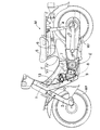
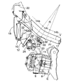
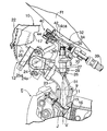
図1〜図4は本発明の参考例を示すもので,図1はバックボーン型自動二輪車の側面図,図2は同自動二輪車のエンジン及び吸気系周りの側面図,図3は図2の吸気系における燃料噴射装置周りの拡大側面図図,図4は図3の4矢視図,図5は本発明の実施例を示す,図3と同様の側面図である。 1 to 4 show a reference example of the present invention, FIG. 1 is a side view of a backbone type motorcycle, FIG. 2 is a side view of an engine and an intake system around the motorcycle, and FIG. 3 is an intake view of FIG. enlarged side view showing around a fuel injection device in the system, Figure 4 is 4 arrow view of FIG. 3, FIG. 5 is a real施例shows a similar side view to FIG. 3 of the present invention.
先ず,図1〜図4により本発明の参考例について説明する。図1において,自動二輪車Mの車体フレームFは,前端のヘッドパイプ1の後側面に溶接されて,後方下向きに傾斜して延びる鋼管からなるバックボーンFfと,このバックボーンFfの後端に溶接される鋼板製のリアフレームFrとか構成される。ヘッドパイプ1には,前輪Wfを軸支するフロントフォーク2が操向可能に枢支され,リアフレームFrには,後輪Wrを軸支するリアフォーク3が枢支され,このリアフォーク3とリアフレームFr間にリアクッション4が連結される。またリアフレームFrの上面にサドル5が取付けられ,このサドル5の直下のリアフレームFr内に燃料タンク6が収納,保持される。さらにリアフレームFrの前端には,バックボーンFfとの結合点の下方において,エンジンEのクランクケース7が取付けられる。エンジンEは,クランクケース7の前面から突出して略水平に配置されるシリンダブロック8を有し,その前面にシリンダヘッド9が接合される。バックボーンFfの前端部にはエアクリーナ10が取付けられ,これとシリンダヘッド9の吸気ポート(図2参照)との間が,バックボーンFfの下方に配置される吸気通路12を介して接続される。
First, a reference example of the present invention will be described with reference to FIGS. In FIG. 1, a vehicle body frame F of a motorcycle M is welded to the rear side surface of the head pipe 1 at the front end, and is welded to a backbone Ff made of a steel pipe extending obliquely rearward and downward, and to the rear end of the backbone Ff. A rear frame Fr made of a steel plate is configured. A front fork 2 that pivotally supports the front wheel Wf is pivotally supported on the head pipe 1 and a rear fork 3 that pivotally supports the rear wheel Wr is pivotally supported on the rear frame Fr. The rear cushion 4 is connected between the rear frames Fr. A saddle 5 is attached to the upper surface of the rear frame Fr, and the
上記バックボーンFf,シリンダブロック8,シリンダヘッド9,エアクリーナ10及び吸気通路12は,車体フレームFに取付けられるレッグシールド13により覆われる。
The backbone Ff, the
図2及び図3に示すように,前記バックボーンFfは,ヘッドパイプ1に結合して後方下向きに傾斜して直線状に延びる前半直線部14aと,この前半直線部14aより緩傾斜で後方下向きに直線状に延びてリアフレームFrに結合する後半直線部14bと,これら両直線部14a,14b間を連続的に結合する,曲率半径Rの中間屈曲部14cとからなっている。その中間屈曲部14cの下方にシリンダヘッド9が位置しており,シリンダヘッド9の上面に吸気ポート11が開口している。この吸気ポート11の燃焼室16への開口端は吸気弁15により開閉される。
As shown in FIGS. 2 and 3, the backbone Ff is coupled to the head pipe 1 and has a front half
前記エアクリーナ10は,バックボーンFfの前半直線部14aの直下に配置されて前面を開放したクリーナケース17と,このクリーナケース17に結合されてその開放面を閉じるケースカバー18と,これらクリーナケース17及びケースカバー18間に挟持されるクリーナエレメント19と,ケースカバー18の上端に連結される入口ダクト20とから構成され,クリーナケース17の底壁に吸気通路12の接続孔21が設けられている。そして入口ダクト20及びクリーナケース17がバックボーンFfの前半直線部14aにねじ止めされる。
The
以上は,従来の小型自動二輪車のレイアウトと変わりがない。 The above is no different from the layout of a conventional small motorcycle.
前記吸気通路12は,前記接続孔21に嵌着されてクリーナケース17内に突入したホーン管22と,前記吸気ポート11に連通すべくシリンダヘッド9の上面に結合される吸気管23と,これらホーン管22及び吸気管23の間を接続するスロットルボディ24とから構成される。ホーン管22は,中間に鈍角の屈曲部を持ち,下流側開口端を後方下向きした略L字状をなしており,また吸気管23も,中間に鈍角の屈曲部を持ち,上流側開口端を前方上向きにした略L字状をなしている。即ち,吸気管23は,シリンダヘッド9の上面から立ち上がりながらバックボーンFfに沿って前方に屈曲しており,特に,その屈曲は,シリンダヘッド9との接合面から開始している。このように屈曲した吸気管23とバックボーンFfとの間にはスペースSが確保される。前記両管22,23を接続すべく傾斜して配置されるスロットルボディ24は,両管22,23の内部を連通する直線状の吸気道24aを有し,この吸気道24aを開閉するバタフライ型のスロットル弁25が,その回動軸25aをバックボーンFfの軸線Yと直交する水平方向に向けてスロットルボディ24に軸支される。前記吸気管23は,そのシリンダヘッド9上面との接合面と,スロットルボディ24の下流端との接合面とが鋭角をなすように形成される。こうして,吸気通路12は,概ねバックボーンFfに沿ってその下方に配置される。
The
略L字状の吸気管23の屈曲部の上側壁に電磁式の燃料噴射弁30が立設される。即ち,吸気管23の屈曲部の上側壁には,水平方向の上端面と,この上端面に開口する鉛直方向の弁装着孔26とを有するボス27が一体に形成され,その弁装着孔26に燃料噴射弁30の下端部がシール部材28を介して嵌装される。この燃料噴射弁30の上端面には燃料入口が,下端面には燃料噴孔がそれぞれ開口しており,その下端面は吸気管23内に臨んでいる。この燃料噴射弁30は,その鉛直方向に延びる下方延長軸線Jと前記吸気弁12の軸線Vとが前記吸気ポート11内で交差するように配置され,その燃料噴孔からの噴射燃料31が前記吸気ポート11の特に吸気弁15により開閉される下流端に向かうようになっている。また燃料噴射弁30は,その上端が前記バックボーンFfの中間屈曲部14cにおける外側曲線14caの中点32より前方にくるように配置される。
An electromagnetic
図3及び図4に示すように,燃料噴射弁30の上端部には,燃料供給管34の側壁に開口する装着孔35がシール部材36を介して嵌合される。この燃料供給管34は,バックボーンFfの直下において,バックボーンFfの軸線Yと直交して水平に,即ち車体の左右方向に配置される。この燃料供給管34に一端には,前記燃料タンク6内に配設される燃料ポンプ38(図1参照)の吐出ポートに連なる燃料導管39が接続され,またその他端には,噴射圧力レギュエータ40が連結される。こうして,吸気管23の上側壁に立設される燃料噴射弁30と,その上端部に接続される燃料供給管34とは,燃料噴射弁30をバックボーンFfの下方で且つそれの中間屈曲部14cの外側曲線14caの中点32よりも前方に配置すると共に,燃料供給管34をバックボーンFfの下面に対向接近させながら,前記スペースSに収められる。またこれら燃料噴射弁30及び燃料供給管34の上部は前記バックボーンFfにより,同下部は前記シリンダヘッド9により,同前面は前記吸気通路12により,同左右側部は前記レッグシールド13によりそれぞれ覆われる。
As shown in FIGS. 3 and 4, a mounting
図4に示すように,噴射圧力レギュエータ40は,燃料供給管34に連通する燃料室41を有するレギュエータボディ42と,ブースト負圧室43を有してレギュエータボディ42に結合されるキャップ44と,レギュエータボディ42及びキャップ44間に挟持されて上記燃料室41及びブースト負圧室43間を仕切るダイヤフラム45とを備える。レギュエータボディ42の中心部には,燃料戻し孔46が開口する弁座47が設けられ,この弁座47に着座し得る弁体48がダイヤフラム45の中心部に首振り可能に付設される。そしてこの弁体48をダイヤフラム45を介して弁座47側に付勢する弁ばね49が
ブースト負圧室43に収容される。ブースト負圧室43は,負圧導管50を介して前記吸気管23内に連通し,燃料戻し孔46は,燃料戻し管51を介して前記燃料タンク6に連通する。さらに燃料室41には燃料フィルタ52が設けられる。
As shown in FIG. 4, the
次に,この参考例の作用について説明する。 Next, the operation of this reference example will be described.
エンジンEの作動中,噴射圧力レギュエータ40の燃料室41には,燃料タンク6内の燃料が燃料ポンプ38により燃料導管39及び燃料供給管34を通して圧送され,その燃料圧力は弁体48を弁座47から離座する方向にダイヤフラム45に作用する。一方,ブースト負圧室43には,吸気管23内のブースト負圧が負圧導管50を通して導入され,このブースト負圧は,弁ばね49の荷重方向とは反対に,弁体48を弁座47から離座する方向にダイヤフラム45に作用する。したがって,エンジンEの負荷が小さくてブースト負圧が高い時は,燃料室41の燃料による弁体48の開弁圧力は低く,エンジンEの負荷が大きくてブースト負圧が低い時は,燃料室41の燃料による弁体48の開弁圧力は高くなり,弁体48の開弁時,燃料室41から燃料戻し孔46に流出した燃料戻し管51を通して燃料タンク6に還流する。こうして燃料供給管34内に燃料圧力は,エンジンEの負荷に応じて制御される。
During operation of the engine E, the fuel in the
而して,エンジンEの吸気行程時,吸気弁15が開くと共に,燃料噴射弁30が励磁されて開弁すると,上記のように圧力制御された燃料が該弁30から噴射され,その噴射燃料31は吸気ポート11の,吸気弁15により開放された下流端に向かうので,エアクリーナ10で濾過されて吸気通路12を流下する吸入空気と共に効率良く燃料室41に吸入される。したがって,噴射燃料31の管壁への付着によるロスが少なく,燃費の低減に寄与し得る。またエアクリーナ10及び吸気ポート11間を結ぶ吸気通路12は,ホーン管22及び吸気管23が鈍角に屈曲するだけで,全体としては後方下向きに傾斜しているので,吸気抵抗が小さくなり,エンジンEの出力向上に寄与し得る。
Thus, during the intake stroke of the engine E, when the
ところで,燃料噴射弁30は,吸気管23の屈曲部の上側壁に立設され,該弁30がバックボーンFfの中間屈曲部14cにおける外側曲線の中点32より前方にくるように配置されるので,従来の車体フレームFやエンジンEのレイアウトを変更せずとも,バックボーンFf及び吸気通路12間の狭小なスペースSを合理的に利用して,該吸気通路12の上側壁に燃料噴射弁30を取付けることができ,したがって上述のように該弁30から吸気ポート11の特に下流端に向かって燃料を噴射することが可能となる。
Incidentally, the
また燃料噴射弁30の上端に連結する燃料供給管34は,バックボーンFfの軸線と直交して水平に配置されるので,バックボーンFf及び燃料噴射弁30間の狭小な空間に燃料供給管34を,バックボーンFfに干渉されることなく容易に配置することができる。
In addition, the
次に,図5により,本発明の実施例について説明する。 Next, referring to FIG. 5, described real施例of the present invention.
この実施例では,燃料噴射弁30の上端に接続される燃料供給管(34)が,それの上流端部側が後方下向きとなるようにバックボーンFfの下側面に沿って傾斜配置される点,この燃料供給管34の上流端部にバックボーンFfに沿って配置される燃料導管39が接続される点,及び燃料供給管34の前端に噴射圧力レギュエータ40のレギュエータボディ42が一体に連設される点を除けば,前記参考例と同様構成であり,図中,前記参考例との対応部分には,同一の参照符号を付して,その説明を省略する。
In the real施例this, the fuel supply pipe that will be connected to the upper end of the fuel injection valve 30 (34), that the upstream end side of which is arranged in an inclined manner along the lower side of the backbone Ff such that the rear downward A
而して,燃料供給管34が,それの上流端部側が後方下向きとなるようにバックボーンFfの下側面に沿って傾斜配置されるされるので,この場合もバックボーンFf及び燃料噴射弁30間の狭小な空間に燃料供給管34を,バックボーンFfに干渉されることなく容易に配置することができる。またその燃料供給管34の後端に接続される燃料導管39がバックボーンFfに沿って配置されるので,燃料導管39がバックボーンFfから大きくはみ出すこともなく,他物との干渉を容易に回避することができる。
Thus, since the
本発明は上記各実施例に限定されるものではなく,その要旨を逸脱しない範囲で種々の設計変更が可能である。 The present invention is not limited to the above embodiments, and various design changes can be made without departing from the scope of the invention.
E・・・・・エンジン
F・・・・・車体フレーム
Ff・・・・バックボーン
Fr・・・・リアフレーム
J・・・・・燃料噴射弁の下方延長軸線
S・・・・・スペース
V・・・・・吸気弁の軸線
Y・・・・・バックボーンの軸線
1・・・・・ヘッドパイプ
2・・・・・フロントフォーク
3・・・・・リアフォーク
8・・・・・シリンダブロック
9・・・・・シリンダヘッド
10・・・・エアクリーナ
11・・・・吸気ポート
12・・・・吸気通路
14a・・・前半直線部
14b・・・後半直線部
14c・・・中間屈曲部
14ca・・中間屈曲部の下面
15・・・・吸気弁
22・・・・第2屈曲部(吸気管)
23・・・・第1屈曲部(ホーン管)
24a・・・直線部(吸気道)
25・・・・スロットル弁
30・・・・燃料噴射弁
34・・・・燃料供給管
38・・・・燃料ポンプ
39・・・・燃料導管
E ... Engine F ... Body frame Ff ... Backbone Fr ... Rear frame J ... Lower extension axis S of fuel injection valve S ... Space V ······· Intake valve axis Y ··· Backbone axis 1 ··· Head pipe 2 ··· Front fork 3 ···
22 ··· Second bent part (intake pipe)
23 ··· First bent part (horn tube)
24a ... straight section (intake passage)
25 ...
38 ... Fuel pump
39 ... ・ Fuel conduit
Claims (2)
前記吸気通路(12)を,前記シリンダヘッド(9)の上面から立ち上がりながら前記バックボーン(Ff)に沿って前方に屈曲する第1屈曲部(23)と,前記エアクリーナ(10)の下面から下がりながら前記バックボーン(Ff)に沿って後方に屈曲する第2屈曲部(22)と,前記第1及び第2屈曲部(22,23)間を連結すべく直線状に延びる直線部(24a)とで構成し,
前記吸気通路(12)の,前記スロットル弁(25)より下流側の前記第1屈曲部(23)の上端壁に立設されて,前記シリンダヘッド(9)の吸気ポート(11)に向かって下向きに燃料を噴射する燃料噴射弁(30)を,前記バックボーン(Ff)の下方で且つそれの中間屈曲部(14c)の外側曲線(14ca)の中点(32)よりも前方に配置し,この燃料噴射弁(30)の鉛直方向に延びる下方延長軸線(J)と前記吸気ポート(11)の下流端を開閉する吸気弁(15)の軸線(V)とが前記吸気ポート(11)内で交差するようにし,
この燃料噴射弁(30)の上端に接続される燃料供給管(34)を,それの上流端部側が後方下向きとなるように前記バックボーン(Ff)の下側面に沿って傾斜配置し,この燃料供給管(34)の上流端部に,前記バックボーン(Ff)に沿って配置されて燃料ポンプ(38)に連なる燃料導管(39)を接続し,
前記燃料噴射弁(30)及び燃料供給管(34)の上部を前記バックボーン(Ff)により,同下部を前記シリンダヘッド(9)により,同前面を前記吸気通路(12)により,同左右側部を前記レッグシールド(13)によりそれぞれ覆ったことを特徴とする,バックボーン型自動二輪車における燃料噴射装置。 Half straight portion from a head pipe (1) Ru extend linearly inclined rearwardly downward to support the front fork (2) (14a), extending linearly rearward downward from the gentle slope the half linear portion (14a) A backbone (Ff) composed of a rear half straight portion (14b) and an intermediate bent portion (14c) continuously connecting the two straight portions (14a, 14b) and a rear end of the backbone (Ff) are integrally coupled. configure the vehicle body frame out with the rear frame (Fr) (F) for supporting the re Ahu forks (3), that the rear frame (Fr), the backbone (Ff) of the cylinder block (8) below and the cylinder head ( 9) An engine (E) that projects substantially horizontally toward the front is mounted, and an intake port (11) that opens to the upper surface of the cylinder head (9), and the backbone (F ) Is connected to an air cleaner (10) disposed at the front end portion via an intake passage (12) disposed below the backbone (Ff) and inclined substantially rearwardly downward. ) Is provided with a throttle valve (25), and a leg shield (13) covering the backbone (Ff), cylinder block (8), cylinder head (9), air cleaner (10) and intake passage (12) is provided. In the backbone type motorcycle mounted on the body frame (F),
A first bent portion (23) that bends forward along the backbone (Ff) while rising from the upper surface of the cylinder head (9) while descending from the lower surface of the air cleaner (10). A second bent portion (22) bent backward along the backbone (Ff) and a linear portion (24a) extending linearly to connect the first and second bent portions (22, 23). Configure
The intake passage (12) is erected on the upper end wall of the first bent portion (23) on the downstream side of the throttle valve (25) toward the intake port (11) of the cylinder head (9). A fuel injection valve (30) for injecting fuel downward is disposed below the backbone (Ff) and in front of the midpoint (32) of the outer curve (14ca) of the intermediate bend (14c) ; A vertically extending axis (J) extending in the vertical direction of the fuel injection valve (30) and an axis (V) of the intake valve (15) for opening and closing the downstream end of the intake port (11) are inside the intake port (11). Cross at
A fuel supply pipe (34) connected to the upper end of the fuel injection valve (30) is inclined along the lower side surface of the backbone (Ff) so that the upstream end side thereof faces downward and rearward. A fuel conduit (39) arranged along the backbone (Ff) and connected to the fuel pump (38) is connected to the upstream end of the supply pipe (34) ,
The upper part of the fuel injection valve (30) and the fuel supply pipe (34) is provided by the backbone (Ff), the lower part thereof is provided by the cylinder head (9), the front surface thereof is provided by the intake passage (12), and the left and right side parts thereof are provided. A fuel injection device for a backbone type motorcycle, which is covered with the leg shield (13).
前記吸気通路(12)の直線部(24a)には前記スロットル弁(25)を配置すると共に,このスロットル弁(25)を,回動軸(25a)が前記バックボーン(Ff)の軸線と直交する水平方向に配置されるバタフライ型に構成し,前記第1屈曲部(23)の,前記吸気ポート(11)に対向する上側壁に,水平方向の上端面と,この上端面に開口する鉛直方向の装着孔(26)とを有するボス(27)を一体に形成し,前記装着孔(26)に前記燃料噴射弁(30)の下端部を嵌装して,その燃料噴孔が開口する下端面を前記第1屈曲部(23)の吸気通路(12)内に臨ませたことを特徴とする,バックボーン型自動二輪車における燃料噴射装置。 In the fuel injection device for a backbone type motorcycle according to claim 1,
The throttle valve (25) is disposed in the straight portion (24a ) of the intake passage (12 ), and the throttle valve (25) is arranged so that the rotation shaft (25a) is orthogonal to the axis of the backbone (Ff). A horizontal butterfly type structure is provided, and an upper side wall of the first bent portion (23) facing the intake port (11) is provided with a horizontal upper end surface and a vertical direction opening to the upper end surface. A boss (27) having a mounting hole (26) is integrally formed, and a lower end portion of the fuel injection valve (30) is fitted into the mounting hole (26) so that the fuel injection hole is opened. characterized in that the end face has to face the intake passage (12) in said first bent portion (23), the fuel injection equipment in backbone type motorcycle.
Priority Applications (1)
| Application Number | Priority Date | Filing Date | Title |
|---|---|---|---|
| JP2008144454A JP5180686B2 (en) | 2008-06-02 | 2008-06-02 | Fuel injection device for backbone type motorcycle |
Applications Claiming Priority (1)
| Application Number | Priority Date | Filing Date | Title |
|---|---|---|---|
| JP2008144454A JP5180686B2 (en) | 2008-06-02 | 2008-06-02 | Fuel injection device for backbone type motorcycle |
Related Parent Applications (1)
| Application Number | Title | Priority Date | Filing Date |
|---|---|---|---|
| JP05469599A Division JP4555413B2 (en) | 1999-03-02 | 1999-03-02 | Fuel injection device for backbone type motorcycle |
Publications (3)
| Publication Number | Publication Date |
|---|---|
| JP2008261340A JP2008261340A (en) | 2008-10-30 |
| JP2008261340A5 JP2008261340A5 (en) | 2010-08-12 |
| JP5180686B2 true JP5180686B2 (en) | 2013-04-10 |
Family
ID=39983977
Family Applications (1)
| Application Number | Title | Priority Date | Filing Date |
|---|---|---|---|
| JP2008144454A Expired - Fee Related JP5180686B2 (en) | 2008-06-02 | 2008-06-02 | Fuel injection device for backbone type motorcycle |
Country Status (1)
| Country | Link |
|---|---|
| JP (1) | JP5180686B2 (en) |
Families Citing this family (2)
| Publication number | Priority date | Publication date | Assignee | Title |
|---|---|---|---|---|
| JP5414423B2 (en) | 2009-08-28 | 2014-02-12 | 本田技研工業株式会社 | Saddle riding |
| JP5264690B2 (en) * | 2009-12-10 | 2013-08-14 | 本田技研工業株式会社 | Scooter type vehicle |
Family Cites Families (9)
| Publication number | Priority date | Publication date | Assignee | Title |
|---|---|---|---|---|
| JP2997750B2 (en) * | 1990-08-08 | 2000-01-11 | ヤマハ発動機株式会社 | Fuel injection engine |
| JPH04234565A (en) * | 1991-01-07 | 1992-08-24 | Toyota Motor Corp | Fuel injection device for internal combustion engine |
| JP3071260B2 (en) * | 1991-09-26 | 2000-07-31 | マツダ株式会社 | Engine intake system |
| JPH0642433A (en) * | 1991-11-08 | 1994-02-15 | Yamaha Motor Co Ltd | Fuel injection type engine |
| JPH06298151A (en) * | 1993-04-19 | 1994-10-25 | Suzuki Motor Corp | Four cycle engine for motorcycle |
| JPH0742654A (en) * | 1993-07-28 | 1995-02-10 | Suzuki Motor Corp | Fuel injection type two-cycle engine |
| JP3586740B2 (en) * | 1996-03-05 | 2004-11-10 | ヤマハ発動機株式会社 | Engine intake structure of underbone type motorcycle |
| JPH10212980A (en) * | 1997-01-31 | 1998-08-11 | Yamaha Motor Co Ltd | Four-cycle engine |
| DE19712591A1 (en) * | 1997-03-26 | 1998-10-01 | Bosch Gmbh Robert | Fuel injector and method for manufacturing and using a fuel injector |
-
2008
- 2008-06-02 JP JP2008144454A patent/JP5180686B2/en not_active Expired - Fee Related
Also Published As
| Publication number | Publication date |
|---|---|
| JP2008261340A (en) | 2008-10-30 |
Similar Documents
| Publication | Publication Date | Title |
|---|---|---|
| JP4555413B2 (en) | Fuel injection device for backbone type motorcycle | |
| US8662518B2 (en) | Vehicle with rotatable fuel tank | |
| JP5520623B2 (en) | Fuel supply device | |
| JP2011073629A (en) | Scooter type vehicle | |
| US20120060799A1 (en) | Vehicle fuel supply device | |
| JP4730244B2 (en) | Intake device for motorcycle | |
| JP5315192B2 (en) | Motorcycle fuel supply system | |
| JP5513271B2 (en) | Vehicle fuel supply device | |
| JP2008230492A (en) | Fuel feeding device for motorcycle | |
| JP5180686B2 (en) | Fuel injection device for backbone type motorcycle | |
| JP4673870B2 (en) | Fuel injection device for backbone type motorcycle | |
| JP5011422B2 (en) | Vehicle fuel supply device | |
| JP2008261340A5 (en) | ||
| JP4648132B2 (en) | Vaporizer arrangement structure in small vehicles | |
| JP6006977B2 (en) | Intake device for motorcycle | |
| JP5180988B2 (en) | Fuel injection device for backbone type motorcycle | |
| JP4999822B2 (en) | Motorcycle | |
| JP2007297049A5 (en) | ||
| JP5380337B2 (en) | Wiring structure to throttle body in small vehicle | |
| JP5778947B2 (en) | Exhaust gas purification device for saddle-ride type vehicles | |
| JP2005138820A (en) | Saddle ride type vehicle | |
| JP5513943B2 (en) | Power unit intake system structure | |
| JP6309406B2 (en) | Saddle riding vehicle | |
| JP2005069232A (en) | Fuel system arrangement structure for motorcycle | |
| JP5862421B2 (en) | Intake device for internal combustion engine for vehicle |
Legal Events
| Date | Code | Title | Description |
|---|---|---|---|
| A521 | Written amendment |
Free format text: JAPANESE INTERMEDIATE CODE: A523 Effective date: 20100628 |
|
| A131 | Notification of reasons for refusal |
Free format text: JAPANESE INTERMEDIATE CODE: A131 Effective date: 20110427 |
|
| A521 | Written amendment |
Free format text: JAPANESE INTERMEDIATE CODE: A523 Effective date: 20110620 |
|
| A02 | Decision of refusal |
Free format text: JAPANESE INTERMEDIATE CODE: A02 Effective date: 20110803 |
|
| A521 | Written amendment |
Free format text: JAPANESE INTERMEDIATE CODE: A523 Effective date: 20111104 |
|
| A911 | Transfer of reconsideration by examiner before appeal (zenchi) |
Free format text: JAPANESE INTERMEDIATE CODE: A911 Effective date: 20111111 |
|
| A912 | Removal of reconsideration by examiner before appeal (zenchi) |
Free format text: JAPANESE INTERMEDIATE CODE: A912 Effective date: 20120113 |
|
| A61 | First payment of annual fees (during grant procedure) |
Free format text: JAPANESE INTERMEDIATE CODE: A61 Effective date: 20130111 |
|
| LAPS | Cancellation because of no payment of annual fees |