JP5174496B2 - Optical sensor module - Google Patents
Optical sensor module Download PDFInfo
- Publication number
- JP5174496B2 JP5174496B2 JP2008063595A JP2008063595A JP5174496B2 JP 5174496 B2 JP5174496 B2 JP 5174496B2 JP 2008063595 A JP2008063595 A JP 2008063595A JP 2008063595 A JP2008063595 A JP 2008063595A JP 5174496 B2 JP5174496 B2 JP 5174496B2
- Authority
- JP
- Japan
- Prior art keywords
- light
- optical sensor
- light guide
- sensor module
- light source
- Prior art date
- Legal status (The legal status is an assumption and is not a legal conclusion. Google has not performed a legal analysis and makes no representation as to the accuracy of the status listed.)
- Expired - Fee Related
Links
Images


Description
本発明は、例えば紙葉類等の被識別体を光学的な手法で識別する際に使われる光学センサが備える光学センサモジュールに関し、より詳細には、互いに異なる波長の光を出射する少なくとも2つの光源を備える光学センサモジュールの構成に関する。また、本発明は、そのような光学センサモジュールを備える光学センサに関する。 The present invention relates to an optical sensor module provided in an optical sensor used for identifying an object to be identified such as a paper sheet by an optical technique, and more specifically, at least two light beams that emit light having different wavelengths. The present invention relates to a configuration of an optical sensor module including a light source. The present invention also relates to an optical sensor including such an optical sensor module.
近年、カラーコピーやカラースキャナ等による複製技術の進歩に伴い、例えば有価証券、商品券、クーポン券、入場券、小切手、手形、紙幣等の紙葉類に対して偽造が行われることがある。このために、従来、紙葉類に対して偽造を防止するために、真偽判定(本物であるか、偽物であるかの判定)を可能とする対策が講じられている。 In recent years, forgery of paper sheets such as securities, gift certificates, coupon tickets, admission tickets, checks, bills, banknotes, and the like is sometimes performed with the progress of copying technology using color copying, color scanners, and the like. For this reason, conventionally, in order to prevent counterfeiting of paper sheets, measures have been taken to enable authenticity determination (determination of genuine or fake).
例えば、特許文献1には、可視光域では用紙の分光反射率とほぼ同値であるが、紫外域又は近赤外域の所定波長域では、用紙の分光反射率と異なる分光反射率を有する物質を、用紙に対し情報化して付与した機械識別用紙が紹介されている。このような用紙を、例えば有価証券等の偽造防止を必要とする紙葉類に適用すれば、例えば分光反射量の測定を行うことによって真偽判定や種類判別などを行うことが可能となる。
For example,
上述のような物質を検出するために分光反射量の測定を行う場合、少なくとも2波長の光を用い、その出力比や出力差を用いて紙葉類の識別を行うのが一般的である。これは、1波長の光のみを用いて情報の検出を行う場合には、例えば、紙葉類の汚れや搬送状態の変化等の影響で真偽判定や種類判別を誤る可能性があり、そのような事態を避けるためである。なお、紙葉類を透過する光を用いる例であるが、特許文献2や3に2波長の光を用いて紙葉類の識別を行う例が示されている。
When measuring the amount of spectral reflection in order to detect a substance as described above, it is general to use at least two wavelengths of light and identify the paper sheet using its output ratio or output difference. This is because, when information is detected using only light of one wavelength, for example, there is a possibility that the authenticity determination or the type determination may be mistaken due to the influence of the contamination of the paper sheet or the change in the conveyance state. This is to avoid such a situation. In addition, although it is an example using the light which permeate | transmits paper sheets, the example which identifies the paper sheets using the light of 2 wavelengths is shown by
図23は、2波長の光を用いて紙葉類を識別する光学センサの従来の構成を示す図である。図23に示すように、従来の光学センサ100においては、搬送路104を挟んで、2波長光源101と受光センサ102とが配置される構成となっている。2波長光源101としては、キャンパッケージタイプの2波長LEDや、LEDチップを個々に基板に実装してカバーを施したもの等がある。そして、従来の光学センサ100では、搬送路104を搬送される紙葉105に対して2波長光源101から異なる波長の光を交番点灯し、2波長間における受光センサ102の出力値を相対的に評価して紙葉105の識別を行う。
FIG. 23 is a diagram illustrating a conventional configuration of an optical sensor that identifies paper sheets using light of two wavelengths. As shown in FIG. 23, the conventional
ところで、2波長光源101を用いる場合、物理的な問題から各波長の光の発光点を同一位置とできず、各波長の光について光軸が異なる状態となる。また、LEDチップの取り付け位置における傾きについて、ばらつきが生じることもある。このために、2波長光源を用いる場合には、点灯する光源によって照明領域が異なる状態となって照明領域にムラ(照度ムラ)を生じる。そして、このような照度ムラを生じると、紙葉105の識別を安定して行えないという問題があった。
By the way, when the two-wavelength light source 101 is used, the light emission points of the light of each wavelength cannot be located at the same position due to physical problems, and the optical axes are different for the light of each wavelength. In addition, the inclination at the mounting position of the LED chip may vary. For this reason, when a two-wavelength light source is used, the illumination area varies depending on the light source to be turned on, and unevenness (illuminance unevenness) occurs in the illumination area. When such unevenness in illuminance occurs, there is a problem that the
このために、従来の光学センサ100においては、図23に示すように、2波長光源101と搬送路104との間の光路上に照射光を拡散する拡散板103が配置された構成となっている。このように拡散板103を設けると、上述の照度ムラを低減できるために、紙葉105の識別を安定して行うことが可能になるとされる。
しかしながら、2波長光源を用いる光学センサに対して上述のような拡散板を設ける場合には、通常は拡散板としては乳白色の樹脂が使用されるために透過率が低下する。そして、満足のいくレベルまで照度ムラを抑制しようとすると透過率がかなり低下する傾向にあり、検出センサで検出される光量が不足して、識別を正確に行えない場合があった。また、例えば光源から出射される光として紫外域の光を使用する場合には、紫外光の出力が低くなる傾向にあるために、できるだけ光量の低下を抑制したいという要求がある。このような点からも、従来とは異なる構成が要求されていた。 However, when a diffusion plate as described above is provided for an optical sensor using a two-wavelength light source, the transmissivity is lowered because a milky white resin is usually used as the diffusion plate. Then, when trying to suppress the illuminance unevenness to a satisfactory level, the transmittance tends to be considerably reduced, and the amount of light detected by the detection sensor is insufficient, and the identification may not be performed accurately. In addition, for example, when ultraviolet light is used as light emitted from the light source, the output of ultraviolet light tends to be low, so there is a demand to suppress the reduction in the amount of light as much as possible. Also from such a point, a configuration different from the conventional one has been required.
以上の点を鑑みて、本発明の目的は、互いに異なる波長の光を出射する少なくとも2つの光源を備える光学センサモジュールであって、いずれの光源を用いる場合にも同様の光強度分布を有する光を出射でき、光量の損失を低く抑えられる光学センサモジュールを提供することである。また、本発明の他の目的は、そのような光学センサモジュールを備えることにより、高い識別能力を有する光学センサを提供することである。 In view of the above points, an object of the present invention is an optical sensor module including at least two light sources that emit light having different wavelengths, and has the same light intensity distribution when any of the light sources is used. It is to provide an optical sensor module that can emit light and suppress the loss of light amount to a low level. Another object of the present invention is to provide an optical sensor having high discrimination ability by including such an optical sensor module.
上記目的を達成するために第一の局面の発明は、被識別体の識別に用いられる光学センサが備える光学センサモジュールであって、光源と、前記光源と前記被識別体との間の光路上に配置され、前記光源からの光を第1の端面から前記第1の端面と対向する第2の端面へと伝播させる導光体と、を備え、前記導光体は、偶数角の角柱形状を有した導光路を有し、前記第1の端面には、光を拡散させる拡散面が形成されることを特徴としている。この構成では、前記導光体は、四角柱、六角柱及び八角柱のうちのいずれか一つの形状から成る導光路を有しているのが好ましい。また、前記光源は、互いに異なる波長の光を出射する複数の光源からなるのが好ましい。そして、前記複数の光源は基板上に並設されているのが好ましい。
In order to achieve the above object, an invention according to a first aspect is an optical sensor module provided in an optical sensor used for identifying an object to be identified, which is on an optical path between a light source and the light source and the object to be identified. And a light guide that propagates light from the light source from a first end face to a second end face facing the first end face, and the light guide has an even-angled prism shape It has a light guide path having a wherein the first end surface, is characterized in that diffusing surface for diffusing light is formed. In this configuration, it is preferable that the light guide has a light guide path formed of any one of a quadrangular column, a hexagonal column, and an octagonal column. Moreover, it is preferable that the said light source consists of several light sources which radiate | emit the light of a mutually different wavelength. The plurality of light sources are preferably arranged side by side on the substrate.
本構成によれば、導光体が偶数角の角柱形状を有した導光路を有する構成となっている。このために、光源から導光体に入射した光が漏れる可能性を低くでき、光の損失を低減できる。また、導光体の光が入射する側の端面を拡散面としている。このために、導光体に入射する光について、光を拡散した状態で導光体に入射させることになり、導光体から出射する光をなるべく均一な状態とすることが可能となる。従って、本構成によれば、光学センサモジュールが備えるいずれの光源から出射される光についても、ほぼ同様の光強度分布を有する光として導光体から出射できる。そして、導光体での光の漏れが少ないために、いずれの光源から出射される光についても光量ロスを低く抑えて、導光体から出射できる。
According to this configuration, the light guide body has a configuration having a light guide path having a prism shape of an even angle. For this reason, possibility that the light which injected into the light guide from the light source will leak can be made low, and the loss of light can be reduced. In addition, the end surface on the light incident side of the light guide is a diffusion surface. For this reason, the light incident on the light guide is incident on the light guide in a diffused state, and the light emitted from the light guide can be made as uniform as possible. Therefore, according to this configuration, light emitted from any light source included in the optical sensor module can be emitted from the light guide as light having substantially the same light intensity distribution. And since there is little leakage of the light in a light guide, it can radiate | emit from a light guide, suppressing light quantity loss low about the light radiate | emitted from any light source.
また上記構成において、前記拡散面は、縦横方向に規則的に設けられる複数の凹部を有し、前記縦横方向の各々について、隣り合う前記凹部は部分的に重なるように形成されることとしても良い。そして、具体的な構成として、前記凹部は、半円筒状の溝であることとできる。 In the above configuration, the diffusion surface may include a plurality of concave portions regularly provided in the vertical and horizontal directions, and the adjacent concave portions may be formed to partially overlap each other in the vertical and horizontal directions. . As a specific configuration, the concave portion can be a semi-cylindrical groove.
このような構成によれば、各光源から出射されて導光体に入射する光について、導光体入射時に外部に反射され難い構造を実現することが可能となる。すなわち、各光源から出射され、導光体内を伝播した後に出射される光について、光量ロスを低く抑えることが可能となる。 According to such a configuration, it is possible to realize a structure in which light emitted from each light source and incident on the light guide is not easily reflected outside when the light guide is incident. That is, it is possible to reduce the light amount loss for light emitted from each light source and emitted after propagating through the light guide.
また上記構成において、前記導光体は、前記第1の端面側に設けられる八角柱形状の導光路と、前記第2の端面側に設けられる円柱形状の導光路と、を有することとするのが好ましい。 In the above configuration, the light guide has an octagonal prismatic light guide provided on the first end face side and a cylindrical light guide provided on the second end face side. Is preferred.
本構成によれば、被識別体の搬送路側に配置されることがある導光体の一方の端面(光源からの光が出射される側の端面)が円形となる。このために、搬送路を搬送される被識別体が導光体に引っ掛かり難くなる。すなわち、搬送路に面するように導光体が配置されても、搬送抵抗を小さくすることが可能となる。また、導光体の導光路が、八角柱形状と円柱形状との組合せであるために、導光体を伝播する光の光量ロスを低く抑えることが可能となる。 According to this configuration, one end surface (the end surface on the side from which the light from the light source is emitted) of the light guide that may be disposed on the conveyance path side of the identification target is circular. For this reason, it becomes difficult for the identification object conveyed by the conveyance path to be caught by the light guide. That is, even if the light guide is arranged so as to face the conveyance path, the conveyance resistance can be reduced. In addition, since the light guide path of the light guide is a combination of an octagonal prism shape and a cylindrical shape, it is possible to reduce the light amount loss of light propagating through the light guide.
また上記構成において、前記光源及び前記基板を収容するハウジング部を更に備え、前記導光体と前記ハウジング部は一体的に形成されることとするのが好ましい。このように構成すれば、光学センサモジュールを容易に形成することが可能となる。 In the above-described configuration, it is preferable that the light source and the housing portion are further formed so that the light guide and the housing portion are integrally formed. If comprised in this way, it will become possible to form an optical sensor module easily.
また上記構成において、前記光源の数は2つであって、一方は青色光を出射し、他方は紫外光を出射することとしても良い。 In the above configuration, the number of the light sources may be two, one emitting blue light and the other emitting ultraviolet light.
また、上記目的を達成するために、第二の局面の発明である光学センサは、上記構成の光学センサモジュールと、前記被識別体からの光を受光する受光部と、を備えることを特徴としている。 In order to achieve the above object, an optical sensor according to a second aspect of the invention includes the optical sensor module configured as described above and a light receiving unit that receives light from the identification target. Yes.
本構成によれば、複数の光源のいずれを用いた場合にも、導光体から出射される光の強度分布を同様とでき、被識別体に対してほぼ同一位置に同様の状態の光を照射することが可能となる。また、光源から出射される光について、光量ロスを抑えて被識別体に照射することが可能である。従って、被識別体からの光を受光部で受光し、そこから出力される信号を処理して被識別体の識別を行う場合に、識別を正確に行うことが可能となる。すなわち、本構成によれば、高い識別能力を有する光学センサの提供が可能となる。 According to this configuration, when any of a plurality of light sources is used, the intensity distribution of the light emitted from the light guide can be made the same, and the light in the same state can be placed at substantially the same position with respect to the identification target. Irradiation is possible. In addition, the light emitted from the light source can be irradiated to the identification object while suppressing the light amount loss. Accordingly, when the light from the identification target is received by the light receiving unit and the signal output from the light receiving unit is processed to identify the identification target, the identification can be accurately performed. That is, according to this configuration, it is possible to provide an optical sensor having a high discrimination capability.
また上記構成において、前記受光部は、前記被識別体を透過した透過光を受光することとしても良い。これによれば、例えば有価証券、商品券、クーポン券、入場券、小切手、手形、紙幣等の紙葉類のように光を透過する被識別体への適用が行い易い。 Moreover, the said structure WHEREIN: The said light-receiving part is good also as receiving the transmitted light which permeate | transmitted the said to-be-identified body. According to this, for example, it is easy to apply to an object to be identified such as securities, gift certificates, coupon tickets, admission tickets, checks, bills, bills, and other paper sheets.
本発明によれば、互いに異なる波長の光を出射する少なくとも2つの光源を備える光学センサモジュールであって、いずれの光源を用いる場合にも同様の光強度分布を有する光を出射でき、光量の損失を低く抑えられる光学センサモジュールを提供することができる。また、本発明によれば、そのような光学センサモジュールを備えることにより、高い識別能力を有する光学センサを提供することができる。 According to the present invention, an optical sensor module including at least two light sources that emit light having different wavelengths can emit light having the same light intensity distribution when any of the light sources is used. It is possible to provide an optical sensor module that can keep the above low. In addition, according to the present invention, by providing such an optical sensor module, an optical sensor having a high discrimination capability can be provided.
以下、本発明の光学センサモジュール及び光学センサの実施形態について、図面を参照しながら説明する。なお、本発明の光学センサモジュール及び光学センサは、例えば被識別体の真偽判定や分類等に使用される。ここで、被識別体としては、例えば、例えば有価証券、商品券、クーポン券、入場券、小切手、手形、紙幣等の紙葉類や、プリペードカード、クレジットカード等のカード類等が該当する。また、以下の説明においては、本発明の光学センサモジュールは、光源側の光学センサモジュールと表現されることがある。 Hereinafter, embodiments of an optical sensor module and an optical sensor of the present invention will be described with reference to the drawings. Note that the optical sensor module and the optical sensor of the present invention are used, for example, for authenticity determination and classification of an identification object. Here, examples of the object to be identified include securities, gift certificates, coupons, admission tickets, checks, bills, paper sheets such as banknotes, and cards such as prepaid cards and credit cards. In the following description, the optical sensor module of the present invention may be expressed as an optical sensor module on the light source side.
(光学センサモジュールについて)
まず、本発明の光学センサモジュールの実施形態について説明する。図1は、本実施形態の光学センサモジュールの構成を示す概略平面図で、図1(a)は側面から見た図、図1(b)は導光体が突出する側から見た図である。図2は、本実施形態の光学センサモジュールの構成を示す概略斜視図である。図3は、図2に示す本実施形態の光学センサモジュールを裏面側から見た場合の概略斜視図である。図3においては、説明の便宜のため、本実施形態の光学センサモジュールが備える光源及び光源が載置される回路基板については省略して示している。
(About optical sensor module)
First, an embodiment of the optical sensor module of the present invention will be described. 1A and 1B are schematic plan views showing the configuration of the optical sensor module of the present embodiment. FIG. 1A is a view seen from the side, and FIG. 1B is a view seen from the side from which the light guide projects. is there. FIG. 2 is a schematic perspective view showing the configuration of the optical sensor module of the present embodiment. FIG. 3 is a schematic perspective view of the optical sensor module of the present embodiment shown in FIG. 2 when viewed from the back side. In FIG. 3, for convenience of explanation, the light source included in the optical sensor module of the present embodiment and the circuit board on which the light source is placed are omitted.
図1から図3を参照して、本実施形態の光学センサモジュール1は、第1光源11と、第2光源12と、光源用回路基板13と、収容ケース14と、導光体15と、を備える。以下、各構成要素について説明する。
1 to 3, the
第1光源11と第2光源12とは、例えばLED(Light emitting diode;発光ダイオード)を用いて構成される。また、第1光源11と第2光源12とは、異なる波長の光を出射するように設けられる。第1光源11及び第2光源12が出射する光の波長は、被識別体が有する識別情報(例えば、被識別体に印刷される特殊インクによる情報)の性質によって適宜選択される。すなわち、光源から出射される2つの波長の組合せとして、例えば青色光と紫外光との組合せや、赤色光と赤外光との組合せ等が適宜選択される。
The
このような第1光源11と第2光源12とは、種類の異なる2つのLED素子を用いて構成しても良いし、1つの素子で2波長の光を出射できるキャンタイプの2波長LEDを用いて構成しても良い。本実施形態では、例えば低コストとできる点や、付け替えを自由に行い易く、組合せの自由度が高い点などを考慮して、2つのLED素子を用いる構成としている。なお、光源はLEDに限らず、例えば半導体レーザ等の他の発光素子を用いる構成としても構わない。
The
光源用回路基板13は、第1光源11及び第2光源12となる2つのLED素子が実装される回路基板である。この光源用回路基板13には、例えば、第1光源11及び第2光源12の点灯と消灯の切替えやその発光量の調整が可能となるように、光源駆動用の回路が形成されている。光源用回路基板13には、コネクタが取り付けられ、これにより外部から電気信号の入力が可能となっている。なお、光源用回路基板13に実装される2つのLED素子は、その間隔がなるべく小さくなるように並設される。
The light
収容ケース14は、第1光源11、第2光源12及び回路基板13を収容するためのハウジング部として機能する。また、本実施形態においては、収容ケース14は、その詳細は後述する導光体15と一体となって形成される。このために、収容ケース14は透明樹脂(例えばアクリル樹脂)で形成されている。また、本実施形態の収容ケース14は、段差が設けられて側面視略L字状となっている。これは、本実施形態の光学センサモジュール1の取り付けに便利な構造とするためで、この点は必要に応じて設計変更して構わない。
The
なお、本実施形態においては、光学センサモジュール1の装置(例えば、被識別体を搬送する搬送装置等)への取り付けを考慮して、収容ケース14が有する段差部分の低い側14aに貫通孔14bが形成されている。
In the present embodiment, in consideration of attachment of the
導光体15は、第1光源11及び第2光源12から出射される光を第1の端面15aから第2の端面15b(図1(a)に示すように第1の端面15aと対向配置される)へと伝播させる役割を有する。そして、本実施形態の導光体15は、第1光源11と第2光源12とから出射される各光について、略円形状に形成される第2の端面15bから同様の光強度分布を有する状態で出射するように形成されている。
The
上述のように導光体15は透明樹脂で形成される。透明樹脂の具体例としては、例えばアクリル樹脂等が挙げられる。ただし、本実施形態においては、紫外光を出射するLED素子を使用する場合を考慮して、紫外光の透過率が低いアクリル樹脂ではなく、紫外光の透過率が高いアクリル樹脂を用いている。このようなアクリル樹脂としては、例えばアクリペットVH000(アクリペットは登録商標;三菱レイヨンのメタクリル樹脂成形材料で、無色透明の樹脂)が挙げられる。
As described above, the
導光体15は、図1及び図2に示すように主に八角柱形状の部分から成るが、第2の端面15b側において一部円柱形状となっている。すなわち、導光体15は、八角柱形状の導光路16と円柱形状の導光路17とを有する構成となっている。導光体15の第2の端面15b側を円柱形状とするのは、光学センサモジュール1を例えば紙葉類の搬送装置(図示せず)にセットした場合において、光源11、12から出射された光の搬送路への窓部として機能する第2の端面15bについて、搬送される紙葉類の搬送抵抗となり難い円形としたいからである。また、本実施形態では、導光体15の第2の端面15b側の外周縁に丸み17a(図1参照)を設け、導光体15が更に搬送抵抗となり難い構成を実現している。
As shown in FIGS. 1 and 2, the
次に、導光体15が八角柱形状の導光路16を有する構成となっている理由について、図4及び図5を参照しながら説明する。図4は、光量のロスを少なくして光を伝播させる場合に、導光体の形状としていずれの角柱形状が有利であるかを説明するための模式図である。図5は、導光体の出射面側の形状を円柱形状とした場合において、光量のロスを少なくするため、いずれの形状の導光体が有利であるかを説明するための模式図である。
Next, the reason why the
導光体内を進行する光は、導光体と導光体の外部との境界で全反射しながら進行する。なお、臨界角以下で境界に入射する光は、全反射することなく外部へと逃げてしまう。図4において、実線は各角柱形状における境界面の種類を示している。一方、破線は黒丸からの光が内部反射を繰り返した場合に得られる、進行する向きが異なる光の数を示している。図4に示すように、偶数角の角柱においては、それぞれ角柱の角数(例えば四角柱なら4、六角柱なら6である)と同数だけ、進行する向きが異なる光が得られる。一方、奇数角の角柱においては、それぞれ角柱の角数(例えば五角柱なら5、七角柱なら7である)の倍の数だけ、進行する向きが異なる光が得られる。 The light traveling in the light guide travels while being totally reflected at the boundary between the light guide and the outside of the light guide. Note that light incident on the boundary at a critical angle or less escapes to the outside without being totally reflected. In FIG. 4, the solid line indicates the type of boundary surface in each prismatic shape. On the other hand, the broken line indicates the number of lights having different traveling directions obtained when light from the black circle repeats internal reflection. As shown in FIG. 4, in an even-angled prism, light traveling in different directions is obtained by the same number as the number of prisms (for example, 4 for a quadrangular prism and 6 for a hexagonal prism). On the other hand, in odd-numbered prisms, light traveling in different directions is obtained by a number that is twice the number of prisms (for example, 5 for pentagonal prisms and 7 for heptagonal prisms).
すなわち、導光体を奇数角の角柱形状とすると、進行する向きが異なる光の数が増え易く、光が境界に臨界角以下で入射する確率が高くなる。このために、導光体から漏れる光の量が多くなる傾向があることがわかる。また、偶数角の角柱形状とする場合には、角柱の角数が大きくなると、進行する向きが異なる光の数が増える。このために、角柱の角数が少ない方が、光量ロスを抑えやすいことがわかる。以上の点からは、導光体が有する導光路の形状として、四角柱、六角柱、八角柱の順に望ましい形態であると言える。 That is, when the light guide is formed in an odd-numbered prismatic shape, the number of lights traveling in different directions is likely to increase, and the probability that light enters the boundary at a critical angle or less increases. For this reason, it turns out that the quantity of the light which leaks from a light guide tends to increase. In the case of a prismatic shape with an even number of angles, the number of lights traveling in different directions increases as the number of prisms increases. For this reason, it can be seen that the smaller the number of prisms, the easier it is to suppress the light loss. From the above points, it can be said that the shape of the light guide path of the light guide is a desirable form in the order of a quadrangular prism, a hexagonal prism, and an octagonal prism.
一方、上述のように、本実施形態においては紙葉類の搬送抵抗を少なくするために、導光体15の第2の端面(出射面)15b側を円柱形状とすることとしている。このため、四角柱、六角柱及び八角柱のいずれかから円柱へと変わる変わり目での光の漏れについて検討が必要となる。これについて、図5に示すように、光が多角柱から円柱へと伝達される際の光の漏れ(光量ロス)は黒塗りの部分で発生する。そして、図5からわかるように、八角柱、六角柱、四角柱の順に光量ロスが大きくなることが分かる。
On the other hand, as described above, in the present embodiment, the second end face (outgoing face) 15b side of the
以上の検討から、導光体が有する導光路の形状を四角柱とすると、光の伝播時の光量ロスは最小とできるが、総合的には光量ロスが多いことがわかった。この点から、導光体が有する導光路の形状としては、四角柱、六角柱、八角柱のいずれかとすることが考えられるが、八角柱、六角柱が好ましく、八角柱がより好ましいことがわかった。そこで、本実施形態の光学センサモジュール1では、導光体15が八角柱の導光路16を有する構成としている。
From the above study, it was found that if the shape of the light guide path of the light guide is a quadrangular prism, the light loss at the time of light propagation can be minimized, but overall, the light loss is large. From this point, it can be considered that the shape of the light guide path of the light guide is one of a quadrangular column, a hexagonal column, and an octagonal column, but an octagonal column and a hexagonal column are preferable, and an octagonal column is more preferable. It was. Therefore, in the
なお、導光体15の第2の端面15b側の形状を円柱形状としないで、導光体を一種類の角柱形状とする構成も考えられる。このような場合には、導光体の形状として、四角柱、六角柱、八角柱の順に好ましい形態と言える。
A configuration in which the shape of the
図1(a)又は図3に戻って、導光体15の第1の端面15a(光源11、12からの光が入射する入射面)には、光を拡散させる拡散面18が形成されている。この拡散面18の詳細について、図6及び図7を参照しながら説明する。図6は、本実施形態の導光体15の第1の端面15bに形成される拡散面18の構成を示す概略平面図である。図7は、図6の拡散面の詳細を説明するための図で、図7(a)は、本実施形態の導光体15の側面図、図7(b)は図7(a)の破線の丸で囲んだ部分を拡大して示した図である。なお、図7においては、紙面に対して垂直な方向をX方向、紙面上下方向をY方向としている。
Returning to FIG. 1A or 3, a
図6に示すように、本実施形態においては、第1の端面15a全体に亘って拡散面18が形成されている。このような拡散面18を形成するのは、導光体15から出射される光の強度分布をできるだけ均一とするためである。この拡散面18は後述のように縦横方向(図6のX方向とY方向)に複数の凹部18aが形成された構造を有し、光源11、12から出射される光を拡散して導光体15内部へと導く役割を果たす。
As shown in FIG. 6, in the present embodiment, a
上述のように、拡散面18に形成される凹部18aは、X方向とY方向とに沿って複数形成されるが、X方向とY方向で同様の方法で凹部18aが形成される。このため、図7(b)を参照しながら、X方向に沿って形成される凹部18aについてのみ説明し、Y方向に沿って形成される凹部18aの説明は省略する。図7(b)を参照して、X方向に形成される凹部18aは、第1の端面15aの平面(拡散面18が形成される前の面で、図7(b)では、符号60で示している)を、X方向に進む直径0.4mmのドリル61(図7(b)ではその断面が示されている)で掘ることによって形成される溝である。本実施形態では、凹部18aは、ドリル61と同一の半径(0.2mm)を有する半円筒状の溝としている。また、この半円筒状の溝(凹部18a)は、Y方向に0.3mmピッチで形成される。このため、X方向に沿って形成される半円筒状の溝は、隣り合う溝と部分的に重なった状態となっている。言いかえると、拡散面18には半径0.2mmの円筒の重なっていない部分が凸部として残っていることになる。
As described above, a plurality of the
ドリル61によって形成される溝の形状は、光源11、12から出射される光が導光体15に入射する際に、導光体15外部に反射してしまう割合をなるべく低くできるように、例えばシミュレーションを行うことによって決められる。また、拡散面18は、ドリル60を用いて導光体15の第1の端面15aを加工することによって得てもよいが、所望の凹部18aを形成可能とする金型を準備し、射出成形等によって形成することにしてもよい。
The shape of the groove formed by the drill 61 is, for example, so that the ratio of the light emitted from the
なお、拡散面の形状は、光源11、12から出射される光を、拡散した状態で導光体15内部へと導くことができ、且つ、なるべく導光体15外部に反射してしまわない形状であれば良く、本実施形態以外の構成でも勿論構わない。
The shape of the diffusing surface is such that light emitted from the
次に、以上のように形成される導光体15の効果について、図8から図10を参照しながら説明する。図8は、本実施形態の導光体(上述のように八角柱と円柱の導光路を有する)に関するシミュレーション結果について説明するための図である。図9は、比較例として行ったシミュレーション結果を説明するための図で、導光体全体を円柱形状に形成した場合の説明図である。図10は、比較例として行ったシミュレーション結果を説明するための図で、導光体を配置せず透明基板のみを配置した場合の説明図である。
Next, the effect of the
なお、図8(a)、図9(a)及び図10(a)は、いずれも、シミュレーション時の発光点及び導光体の位置関係を示す模式図である。また、図8(b)、図9(b)及び図10(b)は、いずれも、導光体から出射される光の強度分布に関するシミュレーション結果を示す図である。図8(b)〜図10(b)において、上段は光の強度分布を示すイメージ図で、白色の部分が導光体から出射される光を示している。また、下段は光の強度分布を示すグラフで、横軸は導光体の中心を通る中心軸Cからの距離を示し、縦軸は光の強度を示す。光の強度分布の観測位置は、図8〜図10で同じ位置としている。 8A, 9 </ b> A, and 10 </ b> A are schematic diagrams showing the positional relationship between the light emitting point and the light guide during simulation. FIGS. 8B, 9B, and 10B are diagrams showing simulation results regarding the intensity distribution of light emitted from the light guide. 8 (b) to 10 (b), the upper part is an image diagram showing the light intensity distribution, and the white part shows the light emitted from the light guide. The lower graph is a graph showing the light intensity distribution, the horizontal axis indicates the distance from the central axis C passing through the center of the light guide, and the vertical axis indicates the light intensity. The observation position of the light intensity distribution is the same position in FIGS.
図8(a)、図9(a)及び図10(a)に示すように、シミュレーションにあたっては、導光体15又は21或いは透明基板22の中心を通る中心軸Cから左側に所定の距離d1だけ離れた位置に、発光点20を配置した。所定の距離d1は、LED素子から成る第1光源11及び第2光源12を図1(b)に示すように配置した場合における2つのLED素子の発光点間の距離に1/2を乗じた距離とした。発光点20から導光体15又は21或いは透明基板22までの距離はいずれも同じ距離d2とした。導光体15及び導光体21には、いずれも、上述の拡散面18(図6及び図7参照)を設けた。導光体15の長さLと幅Wは本実施形態のサイズと同一とし、導光体21の長さLと幅Wは導光体15と同じとした。発光点20から出射される光の波長は例えば450nmとした。
As shown in FIGS. 8A, 9A, and 10A, in the simulation, a predetermined distance d1 from the central axis C passing through the center of the
以上のような構成で、発光点21から光を出射し、同一位置(図8〜10の各々観測点として示している)を通過する光を観測した結果が、図8(b)、図9(b)又は図10(b)に示されている。図8(b)に示すように、本実施形態の導光体15(上述のように八角柱と円柱の導光路を有する)の場合、導光体15の出射面15bから、左右で光強度分布の偏りが少なく、25000W/m2程度の明るさの光が略均等分布で出射された。一方、全体を円柱形状とした導光体21の場合には、図9(b)に示すように、導光体21の出射面21bから出射される光は、右側に光が偏って左右非対称の光強度分布となった。詳しくは、100000W/m2の明るさが得られる部分と、20000W/m2の明るさしか得られない部分とが偏在する結果となった。また、導光体を配置しない場合には、光が拡散してしまい観測位置を通過する光の量が非常に少なく、明るさが3000W/m2程度と非常に暗くなった。
With the configuration as described above, the result of observing the light emitted from the
図示しないが、発光点を左側から右側に変更した場合には導光体15の出射面15bから出射される光の強度分布は、図8(b)に示す結果と左右が反対となった。すなわち、本実施形態の導光体15によれば、導光体15の中心軸から左右にずれた発光点から出射される光の強度分布はほぼ同様となることがわかる。また、導光体15を配置することによって光の損失を抑制できていることもわかる(図10との比較に基づく)。
Although not shown, when the light emitting point is changed from the left side to the right side, the intensity distribution of the light emitted from the
なお、上述のように本実施形態の光学センサモジュール1では、第1光源11と第2光源12とは異なる波長を出射する構成となっている。このように波長の異なる光が導光体15に入射される場合には、屈折率の違いにより導光体15の出射面(第2の面)15bから出射される光の状態が厳密には変化する。この点、光源11、12と導光体15の位置関係や、導光体15の拡散面18の構成等を調整することにより、第1光源11及び第2光源12から出射される各光について、導光体15の出射面15bから出射される光を同様の光強度分布とすることが可能である。特に、青色光と紫外光のように波長の差があまり大きくない場合には、波長の差による影響は問題のないレベルとし易い。
As described above, in the
本実施形態の導光体15を用いた場合の照明効率について、従来の拡散板を用いた構成との比較結果について説明する。図11は、照明効率を比較するための比較例の構成を示す概略平面図である。図11の構成は、2つの光源111、112から出射される各光について拡散板103を用いて拡散し、拡散板13から出射される光の照度ムラをなくす構成となっている。ここで、拡散板103は、照度ムラのレベルが本実施形態の導光体15を用いた場合と同等のレベルとなるものとした。
The illumination efficiency when the
この実験結果によると、導光体15を用いる本実施形態の光学センサモジュール1の場合には、光源11、12から出射された光の拡散面18への入射効率が65%、導光体15の光伝達効率80%であり、照明効率(入射効率×光伝達効率/100)は52%であった。一方、比較例の場合には、光源111、113から出射された光の拡散板103への入射効率が65%、拡散板103の透過率が30%であり、照明効率(入射効率×透過率/100)は20%であった。
According to this experimental result, in the case of the
以上のように、本実施形態の光学センサモジュール1によれば、導光体15の中心軸に対してずれた位置に配置される第1光源11及び第2光源12の間で、導光体15の出射面15bから出射される光の強度分布を同等とできる。また、拡散板を用いていた従来の構成に比べて、光量の損失を低減できる。
As described above, according to the
(光学センサについて)
次に、本実施形態の光学センサモジュール1を備える光学センサについて説明する。なお、説明にあたっては、光学センサの作用を理解し易くするために、光学センサが被識別体を搬送する搬送装置に取り付けられた構成について説明する。また、本実施形態の光学センサが識別の対象とする被識別体は、図12のような商品券50とする。
(About optical sensors)
Next, an optical sensor including the
図12(a)は、本実施形態の光学センサが識別対象とする商品券の構成を示す模式図で、図12(b)は、商品券に印刷される特殊インクの性質を説明するためのグラフである。商品券50は、その一部に特殊インク51が印刷されている。特殊インク51が印刷される位置は一例であり、他の場所に印刷される場合もある。
FIG. 12A is a schematic diagram showing the configuration of a gift certificate to be identified by the optical sensor of the present embodiment, and FIG. 12B is a diagram for explaining the properties of special ink printed on the gift certificate. It is a graph. The
商品券50に印刷される特殊インク51は、図12(b)に示すように、可視光域(図12(b)では可視光の一部領域しか示していない)では光の透過率が被識別体を構成する用紙(図12(b)においては特殊インクなしで示される)と同等である。一方、紫外域の所定波長域では、図12(b)に示すように用紙と異なる透過率を有する。以下、本実施形態の光学センサは、このような商品券50の真偽判定を行うために使用されるものであることを前提に説明する。
As shown in FIG. 12B, the special ink 51 printed on the
まず、本実施形態の光学センサを備える搬送装置の概略について、図13から図15を参照しながら説明する。図13は、本実施形態の光学センサを備える搬送装置の概略側面構造図である。図14は、本実施形態の搬送装置の上段ユニットの概略平面構造図で、底部から見た図である。図15は、本実施形態の搬送装置の下段ユニットの概略平面構造図で、上部から見た図である。 First, an outline of a transport apparatus including the optical sensor according to the present embodiment will be described with reference to FIGS. FIG. 13 is a schematic side structure diagram of a transport apparatus including the optical sensor of the present embodiment. FIG. 14 is a schematic plan view of the upper unit of the transport device of the present embodiment, as viewed from the bottom. FIG. 15 is a schematic plan view of the lower unit of the transport apparatus according to the present embodiment, as viewed from above.
図13に示すように、本実施形態の搬送装置30は、上段ユニット31と下段ユニット32とを備える。商品券50は、上段ユニット31と下段ユニット32との間の搬送路33を図示P方向に搬送される。上段ユニット31には光源側の光学センサモジュール1が設けられる。そして、下段ユニット32には、光源側の光学センサモジュール1と搬送路33を挟んで対向するように、受光側の光学センサモジュール41が配置される。この2つの光学センサモジュール1、41が一対と成って本実施形態の光学センサ40を構成する。
As shown in FIG. 13, the
上段ユニット31には、ローラ311及び312が設けられる。ローラ311及びローラ312の間には2本の搬送ベルト313a、313bが巻回される。搬送ベルト313a、313bは各々、スプリング、バネ等の弾性材で成る付勢手段34によって下段ユニット32側に付勢される。ローラ311、312が図13に示す矢印の方向に回転すると、付勢手段34の商品券50への付勢作用及び搬送ベルト313a、313bのP方向への移動によって、搬送路33に供給された商品券50が搬送される。
The
また、上段ユニット31に取り付けられる光源側の光学センサモジュール1は、2つの搬送ベルト313a、313bの間のほぼ中間位置に位置している。光学センサモジュール1は、着脱が容易にできるようにモジュールケース37に収容された状態で上段ユニット31に取り付けられる。なお、モジュールケース37に窓穴が設けられ、モジュールケース37に収容される光学センサモジュール1は導光体15の第2の端面15b側が表出した状態となっている。
The
下段ユニット32には、2本の搬送ベルト313a、313bに各々対向するように、長方形状のガイド321a、321bが配設される。ガイド321a、321bは、金属又は合成樹脂から成っており、その表面は滑らかに加工されている。これにより、搬送ベルト313a、313bとの間に挟持された商品券50が円滑に搬送されるようになっている。
The
また、下段ユニット32取り付けられる受光側の光学センサモジュール41は、光源側の光学センサモジュール1と同様に、モジュールケース38に収容された状態で取り付けられている。なお、後述のように受光側の光学センサモジュール41は、受光素子が収容ケースに収容された構成となっており、収容ケースに設けられる窓部がモジュールケース38から表出した状態となっている。
The light-receiving side
また、下段ユニット32には、商品券50の挿入部に商品券の通過を検知する商品券通過センサ39が配設されている。更に、下段ユニット32には、CPUを備えて、例えばローラ311、312の駆動の制御や光学センサ40の駆動の制御等、全体の制御を行う制御部35と、光学センサ40からの出力に基づいて商品券50を識別する(真偽判定を行う)識別部36と、が設けられる。
The
次に、本実施形態の光学センサ40の構成について、図16を参照しながら説明する。上述のように、本実施形態の光学センサ40は、光源側の光学センサモジュール1と受光側の光学センサモジュール41とを備える。光源側の光学センサモジュール1は上述の導光体15を備えるモジュールであり、重複する部分については同一の符号を付して、その説明を省略する。
Next, the configuration of the
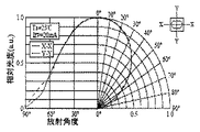
光源側の光学センサモジュール1は、第1光源11として青色LED素子を備える。図17は、本実施形態の光学センサが備える青色LED素子の指向特性を示すグラフである。青色LED素子11は、ピーク波長として例えば450nmの青色光を出射する。また、図17に示すように、X方向とY方向とで同様の指向特性を有する。
The
また、光源側の光学センサモジュール1は、第2光源12としてUV(UltraViolet) LED素子を備える。図18は、本実施形態の光学センサが備えるUV LED素子の指向特性を示すグラフである。UV LED素子12は、ピーク波長として例えば350nmの紫外光を出射する。また、図18に示すように、X方向とY方向とで同様の指向特性を有する。
The
上述のように、第1光源11から出射されて導光体15の第2の端面15bから出射される光と、第2の光源12出射されて導光体15の第2の端面15bから出射される光とは、ほぼ同一の光強度分布を有する。すなわち、第1光源11と第2光源12との点灯のタイミングを高速で切り替えることにより、搬送路33を搬送される商品券50のほぼ同一位置を青色光と紫外光で照射することが可能となる。
As described above, the light emitted from the
受光側の光学センサモジュール41は、受光素子42と、受光用回路基板43と、収容ケース44と、を備える。受光素子42は、第1光源11或いは第2光源12から出射され導光体15を経由して商品券50を照射した光のうち、商品券50を透過した光を受光し、光電変換して電気信号を出力する。このような受光素子42として、本実施形態においては、感度波長域が320〜1100nmで、ピーク感度波長が例えば960nmのシリコン_ピンフォトダイオードを用いている。
The light receiving side
受光用回路基板43は、受光素子42が実装される回路基板である。また、受光用回路基板43には、受光素子42から出力される電気信号を処理して識別部36に出力するための回路が形成されている。また、受光用回路基板43は、制御部35から信号が入力されるようにも回路構成されている。回路構成の詳細については、後述する。なお、受光素子42からの信号の出力、及び受光素子42への信号の入力は、コネクタ45を介して行われる。
The light
収容ケース44は、受光素子42と受光用回路基板43とを収容するハウジング部である。収容ケース44には、窓部44aが設けられており、この部分より商品券50を透過した光が入射して、受光素子42へと導かれる。収容ケース44は、例えばアクリル樹脂によって形成される。
The
次に、本実施形態の光学センサ40の回路構成について図19を参照しながら説明する。図19は、本実施形態の光学センサ40が備える回路構成を示す図である。なお、本実施形態においては、タイミング作成回路351は制御部35に備えられる。タイミング作成回路351は、クロック信号に同期して作成される、点灯信号(B)、点灯信号(UV)、ホールド信号(B)及びホールド信号(UV)を適宜出力する。
Next, the circuit configuration of the
光量制御回路111は、第1光源11の発光光量の制御を行う回路である。また、点灯回路112は、第1光源11の点灯(ON)と消灯(OFF)の制御を行う回路である。なお、点灯回路112の点灯と消灯の制御は、タイミング作成回路351から出力される点灯信号(B)に基づいて行われる。
The light
同様に、光量制御回路121は、第2光源12の発光光量の制御を行う回路である。また、点灯回路122は、第2光源12の点灯(ON)と消灯(OFF)の制御を行う回路である。なお、点灯回路122の点灯と消灯の制御は、タイミング作成回路351から出力される点灯信号(UV)に基づいて行われる。
Similarly, the light
第1増幅回路421は、第1光源11或いは第2光源12の点灯によって商品券50を透過した光を受光した受光素子42からの信号を増幅する。ゲイン切替回路422は、第1増幅回路421からの信号についてゲイン調整を行う回路である。第2増幅回路423は、反転アンプを2つ備え、ゲイン調整を行った信号について2段階で信号の増幅を行う。オフセット回路424は、オフセット調整を行う回路である。
The
第2増幅回路423によって増幅された信号は、バンドパスフィルタから成る2色回路(図示せず)で2つの信号に分けられる。そして、各信号は、サンプルアンドホールド回路425或いは427によって所定のタイミングでサンプルした信号電圧をホールドされる。ホールドは、タイミング作成回路351からのホールド信号(B)或いはホールド信号(UV)に基づいて行われる。
The signal amplified by the
また、サンプルアンドホールド回路425或いは427から出力された各信号は、2次LPF(ローパスフィルタ)426或いは428によってノイズを除去されて、青色光受光信号(SigBで示される)或いは紫外光受光信号(SigUVで示される)として出力される。出力された信号は、識別部36において処理されて商品券50の識別(真偽判定)が行われる。
Further, each signal output from the sample and hold
以上のように、本実施形態の光学センサ40では、1つの受光素子42で青色光と紫外光を受光し、その各々に対して同様の処理を施して識別部36へと出力する構成となっている。このために、2つの波長の光を用い、受光部からの出力を相対的に評して商品券50の識別を行う場合に、波長間での信号処理時のずれが少なくなり、識別精度を高くできる。
As described above, the
このように構成される本実施形態の光学センサ40の組み立て時の調整例について、図20を参照しながら説明する。図20は、本実施形態の光学センサの組み立て時の調整フローを示すフローチャートである。組み立て時の調整としては、まず、受光側のゲイン調整が行われる(ステップS1)。具体的には、基準光を用いて狙いの出力となるようにゲイン切替回路422のボリューム調整を行う。ここで決定された調整値は以後固定とする。
An adjustment example at the time of assembling the
次に、オフセット回路424によって、オフセット設定値のボリューム調整が行われる(ステップS2)。具体的には、光源側の光学センサモジュール1と受光側の光学センサモジュール41との間に黒色の用紙をセットする。すなわち、受光素子42について光が入らない状態(遮光状態)とする。そして、サンプルアンドホールド回路425をホールドとしない状態で、青色受光信号の出力が0Vとなるようにオフセット設定値の調整が行われる。なお、この調整で紫外光受光信号についても同じ値が得られる。
Next, the volume of the offset setting value is adjusted by the offset circuit 424 (step S2). Specifically, a black paper is set between the
次に、第1光源11と第2光源12の発光光量の調整が行われる(ステップS3)。具体的には、光源側光学センサモジュール1と受光側光学センサモジュール41との間に白色の用紙をセットする。この際、白色の用紙のセット位置は所定の位置(例えば、導光体15の第2の端面15bと、受光側の収容ケース44の窓部44aの上面と、の間の中間位置)となるように注意する。
Next, the light emission amounts of the
そして、サンプルアンドホールド回路425をホールドとしない状態で、青色光受光信号が所定の電圧(例えば4V)となるように、光量制御回路111の設定値を調整する。また、同様にサンプルアンドホールド回路427をホールドとしない状態で、紫外光受光信号が青色光受光信号の場合と同じ所定の電圧(例えば4V)となるように、光量制御回路121の設定値を調整する。以上により、光学センサ40の組み立て時の調整は終了する。
Then, the set value of the light
続いて、本実施形態の光学センサ40の動作について、図21を参照しながら説明する。図21は、タイミング作成回路351から出力される各種タイミング信号のタイミングチャートである。例えば、商品券通過センサ39によって搬送路33を搬送される商品券50が検知されると、光学センサ40がタイミング作成回路351のクロック信号に同期して作成される各種タイミング信号に基づいて作動する。
Subsequently, the operation of the
点灯信号(B)がハイレベル信号となると、点灯回路112によって第1光源11が点灯される。したがって、点灯信号(B)がハイレベル信号の場合には、受光素子42は、青色光が商品券50を透過する量を検出することになる。点灯信号(B)がローレベル信号となると第1光源11が消灯され、そのタイミングで点灯信号(UV)がハイレベル信号となる。そして、点灯回路121によって第2光源12が点灯される。したがって、点灯信号(UV)がハイレベル信号の場合には、受光素子42は、紫外光が商品券50を透過する量を検出することになる。
When the lighting signal (B) becomes a high level signal, the
なお、点灯信号(B)と点灯信号(UV)とのハイレベル信号とローレベル信号との切替えは高速に行われ、搬送される商品券50のほぼ同一位置について、青色光と紫外光とを照射した場合の光の透過量を検出することが可能である。
Switching between the high level signal and the low level signal between the lighting signal (B) and the lighting signal (UV) is performed at high speed, and the blue light and the ultraviolet light are changed at substantially the same position of the
また、点灯信号(B)がハイレベル信号となった直後ではなく、少し時間をおいて信号のサンプリングを行い、点灯信号(B)がローレベル信号に切り替わる段階でホールドするように、ホールド信号(B)のハイレベル信号(この時にホールドが行われる)とローレベル信号の切替えが行われるようになっている。このようにホールド信号(B)のハイレベル信号とローレベル信号との切替えを行うのは、第1光源11の発光量が安定した時点でのみ信号のサンプリングを行うためである。
The hold signal (B) is not immediately after the lighting signal (B) becomes a high level signal, but is sampled after a short time so that the signal is held when the lighting signal (B) is switched to the low level signal. Switching between a high level signal (B) (holding is performed at this time) and a low level signal is performed. The reason for switching between the high level signal and the low level signal of the hold signal (B) in this way is to perform signal sampling only when the light emission amount of the
同様に、ホールド信号(UV)は、点灯信号(UV)がハイレベル信号となった直後ではなく、少し時間をおいて信号のサンプリングを行い、点灯信号(UV)がローレベル信号に切り替わる段階でホールドするように、ホールド信号(UV)のハイレベル信号とローレベル信号の切替えが行われる。 Similarly, the hold signal (UV) is not immediately after the lighting signal (UV) becomes a high level signal, but at a stage when the signal is sampled after a while and the lighting signal (UV) is switched to a low level signal. Switching between a high level signal and a low level signal of the hold signal (UV) is performed so as to hold.
以上のように光学センサ40を動作させた場合における、識別部36が商品券50の識別を行う動作について図22を参照しながら説明する。図22は、搬送路33に沿って商品券50を搬送させた場合に、本実施形態の光学センサ40から出力される信号を示した模式図である。図22(a)は、商品券50が本物である場合の出力信号の時間変化を示し、図22(b)は、商品券50が偽物である場合の出力信号の時間変化を示す。
The operation of the
商品券50が本物である場合には、図12(a)に示すように特殊インク51が印刷されている。この場合、青色光受光信号については、特殊インクの有無によって青色光(本実施形態ではピーク波長が例えば450nmの光を使用)の透過率がほとんど変化しないために、特殊インク51が印刷されている部分を通過しても、出力レベルがほぼ一定となる。一方、紫外光受光信号については、特殊インクの有無によって所定波長域の紫外光(本実施形態ではピーク波長が例えば350nmの紫外光を使用)の透過率が変化するために、特殊インクの存在によって出力レベルが変動する。具体的には、図22(a)に示すように、特殊インク51が存在すると紫外光は透過率が下がるために、特殊インク51を検知すると紫外光受光信号の出力レベルは低下する。
When the
一方、商品券50が偽物である場合には、特殊インク51が印刷さていない。このため、図22(b)に示すように、青色光と紫外光とのうち、いずれを照射した場合にも、青色光受光信号及び紫外光受光信号は、ほぼ一定となる。
On the other hand, when the
従って、例えば識別部36において、光学センサ40から出力される紫外光受光信号を青色光受光信号で除する処理を行う。そして、紫外光受光信号を青色光受光信号で除した値について、予め実験することによって得ておいた閾値よりも低いレベルとなる結果が得られれば、商品券50を本物と判断し、そうでなければ商品券50が偽者であると判断できる。本実施形態の識別部36は、そのように構成されている。
Therefore, for example, the
なお、本実施形態の光学センサ40は、上述のように、発光点位置が異なる第1光源11と第2光源12から出射される光について、光強度分布をほぼ同等として商品券50に照射できる。このために、搬送される商品券50に照射される光の状態について、第1光源11と第2光源12とで同等とできる。更に、本実施形態の導光体15を用いる場合、光源11、12から出射される光の損失を少なくして商品券50に光を照射できる。従って、本実施形態の光センサ40を用いれば質の高い識別を行え、例えば商品券50の真偽判定をより正確なものとできる。
As described above, the
(その他)
本発明は、以上に示した実施形態に限定されるものではなく、本発明の目的を逸脱しない範囲で種々の変更が可能である。
(Other)
The present invention is not limited to the embodiment described above, and various modifications can be made without departing from the object of the present invention.
例えば、以上に示した本実施形態の光学センサモジュール1においては、収容ケース14と導光体15とを一体的に形成する構成とした。しかし、この構成に限定される趣旨ではなく、収容ケース14と導光体15とを別々の部材としても良い。ただし、本実施形態のように一体とした方が、組み立てが容易等の点で好ましい。
For example, in the
また、以上に示した本実施形態の光学センサモジュール1においては、2つの光源11、12を備える構成とした。しかし、この構成に限定される趣旨ではなく、3つ以上の光源を備える場合にも本発明は適用可能である。
Further, the
また、以上に示した実施形態では、光学センサモジュール1は透過型の光学センサ40に適用される構成とした。しかし、本発明の光源用の光学センサモジュールは、反射型の光学センサにも勿論適用できる。
In the embodiment described above, the
本発明の光学センサモジュール及び光学センサは、例えば有価証券、商品券、クーポン券、入場券、小切手、手形、紙幣等の紙葉類や、プリペードカード、クレジットカード等のカード類等の被識別体について、その分類や真偽判定等を行うために好適に適用できる。 The optical sensor module and the optical sensor of the present invention are identified objects such as papers such as securities, gift certificates, coupons, admission tickets, checks, bills, banknotes, cards such as prepaid cards and credit cards. Can be suitably applied to perform classification, authenticity determination, and the like.
1 光学センサモジュール(光源側の光学センサモジュール)
11 第1光源
12 第2光源
13 光源用回路基板
14 収容ケース(ハウジング部)
15 導光体
15a 第1の端面
15b 第2の端面
16 八角柱形状の導光路
17 円柱形状の導光路
18 拡散面
18a 凹部
40 光学センサ
41 受光側の光学センサモジュール(受光部)
50 商品券(被識別体)
1 Optical sensor module (optical sensor module on the light source side)
DESCRIPTION OF
DESCRIPTION OF
50 Gift Certificate (identified object)
Claims (7)
光源と、
前記光源と前記被識別体との間の光路上に配置され、前記光源からの光を第1の端面から前記第1の端面と対向する第2の端面へと伝播させる導光体と、
を備え、
前記導光体は、前記第1の端面側に設けられる偶数角の角柱形状の導光路と、前記第2の端面側に設けられる円柱形状の導光路とを有し、
前記第1の端面には、光を拡散させる拡散面が形成されることを特徴とする光学センサモジュール。 An optical sensor module provided in an optical sensor used for identifying an object to be identified,
A light source;
A light guide that is disposed on an optical path between the light source and the object to be identified, and propagates light from the light source from a first end surface to a second end surface facing the first end surface;
With
The light guide includes an even-angle prismatic light guide provided on the first end face side, and a cylindrical light guide provided on the second end face side ,
An optical sensor module, wherein a diffusion surface for diffusing light is formed on the first end surface.
前記導光体と前記ハウジング部は一体的に形成されることを特徴とする請求項6に記載の光学センサモジュール。 A housing portion for accommodating the light source and the substrate;
The optical sensor module according to claim 6, wherein the light guide and the housing portion are integrally formed .
Priority Applications (1)
| Application Number | Priority Date | Filing Date | Title |
|---|---|---|---|
| JP2008063595A JP5174496B2 (en) | 2008-03-13 | 2008-03-13 | Optical sensor module |
Applications Claiming Priority (1)
| Application Number | Priority Date | Filing Date | Title |
|---|---|---|---|
| JP2008063595A JP5174496B2 (en) | 2008-03-13 | 2008-03-13 | Optical sensor module |
Publications (3)
| Publication Number | Publication Date |
|---|---|
| JP2009216678A JP2009216678A (en) | 2009-09-24 |
| JP2009216678A5 JP2009216678A5 (en) | 2011-03-10 |
| JP5174496B2 true JP5174496B2 (en) | 2013-04-03 |
Family
ID=41188675
Family Applications (1)
| Application Number | Title | Priority Date | Filing Date |
|---|---|---|---|
| JP2008063595A Expired - Fee Related JP5174496B2 (en) | 2008-03-13 | 2008-03-13 | Optical sensor module |
Country Status (1)
| Country | Link |
|---|---|
| JP (1) | JP5174496B2 (en) |
Cited By (1)
| Publication number | Priority date | Publication date | Assignee | Title |
|---|---|---|---|---|
| US8699864B2 (en) | 1995-04-27 | 2014-04-15 | Hitachi Consumer Electronics Co., Ltd. | Method and apparatus for receiving a digital signal and apparatus for recording and reproducing the digital signal |
Families Citing this family (2)
| Publication number | Priority date | Publication date | Assignee | Title |
|---|---|---|---|---|
| JP7036699B2 (en) * | 2018-10-12 | 2022-03-15 | アークレイ株式会社 | Optical measuring device |
| CN112697276B (en) * | 2020-12-03 | 2023-07-18 | 长春希达电子技术有限公司 | LED display module ink color collecting method with uneven ink color and sorting method thereof |
Family Cites Families (4)
| Publication number | Priority date | Publication date | Assignee | Title |
|---|---|---|---|---|
| JP2000172898A (en) * | 1998-12-07 | 2000-06-23 | Omron Corp | Paper sheets discriminating device |
| JP4188538B2 (en) * | 2000-04-12 | 2008-11-26 | 浜松ホトニクス株式会社 | Immunochromatographic test piece measuring device |
| JP3518518B2 (en) * | 2001-03-05 | 2004-04-12 | 松下電器産業株式会社 | Banknote recognition device |
| JP4979977B2 (en) * | 2006-04-26 | 2012-07-18 | 三菱電機株式会社 | Surface state determination device, surface state determination method, and surface state determination program |
-
2008
- 2008-03-13 JP JP2008063595A patent/JP5174496B2/en not_active Expired - Fee Related
Cited By (1)
| Publication number | Priority date | Publication date | Assignee | Title |
|---|---|---|---|---|
| US8699864B2 (en) | 1995-04-27 | 2014-04-15 | Hitachi Consumer Electronics Co., Ltd. | Method and apparatus for receiving a digital signal and apparatus for recording and reproducing the digital signal |
Also Published As
| Publication number | Publication date |
|---|---|
| JP2009216678A (en) | 2009-09-24 |
Similar Documents
| Publication | Publication Date | Title |
|---|---|---|
| JP4609531B2 (en) | Image reading device | |
| US8310737B2 (en) | Image reading apparatus | |
| KR101396073B1 (en) | Image sensor unit and image reading apparatus using the same | |
| KR101600207B1 (en) | Image sensor unit and image reading device utilizing same | |
| US7271398B2 (en) | Reflective optical sensor for bill validator | |
| US8836926B2 (en) | Optical detector arrangement for document acceptor | |
| US6994203B2 (en) | Document validator subassembly | |
| JP5174496B2 (en) | Optical sensor module | |
| JP6207359B2 (en) | Illumination device, image sensor unit, and paper sheet identification device | |
| JP2007141109A (en) | Paper sheet discrimination device | |
| JP5431337B2 (en) | Document identifier subassembly | |
| CN105900151A (en) | Linear light source, optical sensor, discrimination unit, and automatic transaction device using same | |
| JP2007141110A (en) | Paper sheet discrimination device | |
| CN112313717B (en) | Optical line sensor unit | |
| JP7111494B2 (en) | Light detection sensor, light detection device, sheet processing device, and light detection method | |
| WO2009110064A1 (en) | Optical sensor and optical waveguide prism | |
| JP2003162748A (en) | Fluorescence detection sensor for paper sheets | |
| JP7089886B2 (en) | Identification device | |
| JP6701625B2 (en) | Light guide device for paper sheet identification device | |
| JP2016110355A (en) | Medium discrimination device and automatic transaction device | |
| JP4721509B2 (en) | Paper sheet detection sensor | |
| CN105814612A (en) | Paper sheet processing device | |
| JP2002183795A (en) | Paper sheet detecting sensor | |
| JP2009246743A (en) | Light guide and print pattern reader for paper sheet or the like |
Legal Events
| Date | Code | Title | Description |
|---|---|---|---|
| A521 | Request for written amendment filed |
Free format text: JAPANESE INTERMEDIATE CODE: A523 Effective date: 20110120 |
|
| A621 | Written request for application examination |
Free format text: JAPANESE INTERMEDIATE CODE: A621 Effective date: 20110120 |
|
| A977 | Report on retrieval |
Free format text: JAPANESE INTERMEDIATE CODE: A971007 Effective date: 20120927 |
|
| A131 | Notification of reasons for refusal |
Free format text: JAPANESE INTERMEDIATE CODE: A131 Effective date: 20121002 |
|
| A521 | Request for written amendment filed |
Free format text: JAPANESE INTERMEDIATE CODE: A523 Effective date: 20121116 |
|
| TRDD | Decision of grant or rejection written | ||
| A01 | Written decision to grant a patent or to grant a registration (utility model) |
Free format text: JAPANESE INTERMEDIATE CODE: A01 Effective date: 20121204 |
|
| A61 | First payment of annual fees (during grant procedure) |
Free format text: JAPANESE INTERMEDIATE CODE: A61 Effective date: 20121228 |
|
| R150 | Certificate of patent or registration of utility model |
Ref document number: 5174496 Country of ref document: JP Free format text: JAPANESE INTERMEDIATE CODE: R150 |
|
| RD03 | Notification of appointment of power of attorney |
Free format text: JAPANESE INTERMEDIATE CODE: R3D03 |
|
| LAPS | Cancellation because of no payment of annual fees |