JP5159370B2 - Image forming apparatus and information processing method - Google Patents
Image forming apparatus and information processing method Download PDFInfo
- Publication number
- JP5159370B2 JP5159370B2 JP2008052088A JP2008052088A JP5159370B2 JP 5159370 B2 JP5159370 B2 JP 5159370B2 JP 2008052088 A JP2008052088 A JP 2008052088A JP 2008052088 A JP2008052088 A JP 2008052088A JP 5159370 B2 JP5159370 B2 JP 5159370B2
- Authority
- JP
- Japan
- Prior art keywords
- jam
- image forming
- job
- forming apparatus
- test job
- Prior art date
- Legal status (The legal status is an assumption and is not a legal conclusion. Google has not performed a legal analysis and makes no representation as to the accuracy of the status listed.)
- Expired - Fee Related
Links
- 230000010365 information processing Effects 0.000 title claims description 11
- 238000003672 processing method Methods 0.000 title claims description 7
- 238000012360 testing method Methods 0.000 claims description 175
- 238000000034 method Methods 0.000 claims description 39
- 238000001514 detection method Methods 0.000 claims description 13
- 238000012790 confirmation Methods 0.000 claims description 12
- 238000011084 recovery Methods 0.000 claims description 6
- 238000007726 management method Methods 0.000 description 59
- 238000010586 diagram Methods 0.000 description 35
- 230000006870 function Effects 0.000 description 24
- 238000012545 processing Methods 0.000 description 12
- 230000005540 biological transmission Effects 0.000 description 9
- 238000012423 maintenance Methods 0.000 description 9
- 238000004891 communication Methods 0.000 description 6
- 238000013500 data storage Methods 0.000 description 6
- 238000012546 transfer Methods 0.000 description 5
- 238000004458 analytical method Methods 0.000 description 3
- 238000006243 chemical reaction Methods 0.000 description 3
- 230000004913 activation Effects 0.000 description 2
- 230000006835 compression Effects 0.000 description 2
- 238000007906 compression Methods 0.000 description 2
- 238000004590 computer program Methods 0.000 description 2
- 230000006837 decompression Effects 0.000 description 2
- 230000014759 maintenance of location Effects 0.000 description 2
- 239000003550 marker Substances 0.000 description 2
- 230000002093 peripheral effect Effects 0.000 description 2
- 230000002159 abnormal effect Effects 0.000 description 1
- 239000000470 constituent Substances 0.000 description 1
- 238000012937 correction Methods 0.000 description 1
- 238000011161 development Methods 0.000 description 1
- 230000000694 effects Effects 0.000 description 1
- 238000010438 heat treatment Methods 0.000 description 1
- 238000003384 imaging method Methods 0.000 description 1
- 238000009434 installation Methods 0.000 description 1
- 238000012544 monitoring process Methods 0.000 description 1
- 230000003287 optical effect Effects 0.000 description 1
- 238000012805 post-processing Methods 0.000 description 1
- 230000004044 response Effects 0.000 description 1
- 230000000717 retained effect Effects 0.000 description 1
- 230000001360 synchronised effect Effects 0.000 description 1
Images


Classifications
-
- G—PHYSICS
- G03—PHOTOGRAPHY; CINEMATOGRAPHY; ANALOGOUS TECHNIQUES USING WAVES OTHER THAN OPTICAL WAVES; ELECTROGRAPHY; HOLOGRAPHY
- G03G—ELECTROGRAPHY; ELECTROPHOTOGRAPHY; MAGNETOGRAPHY
- G03G15/00—Apparatus for electrographic processes using a charge pattern
- G03G15/70—Detecting malfunctions relating to paper handling, e.g. jams
-
- G—PHYSICS
- G03—PHOTOGRAPHY; CINEMATOGRAPHY; ANALOGOUS TECHNIQUES USING WAVES OTHER THAN OPTICAL WAVES; ELECTROGRAPHY; HOLOGRAPHY
- G03G—ELECTROGRAPHY; ELECTROPHOTOGRAPHY; MAGNETOGRAPHY
- G03G15/00—Apparatus for electrographic processes using a charge pattern
- G03G15/50—Machine control of apparatus for electrographic processes using a charge pattern, e.g. regulating differents parts of the machine, multimode copiers, microprocessor control
- G03G15/5012—Priority interrupt; Job recovery, e.g. after jamming or malfunction
-
- G—PHYSICS
- G03—PHOTOGRAPHY; CINEMATOGRAPHY; ANALOGOUS TECHNIQUES USING WAVES OTHER THAN OPTICAL WAVES; ELECTROGRAPHY; HOLOGRAPHY
- G03G—ELECTROGRAPHY; ELECTROPHOTOGRAPHY; MAGNETOGRAPHY
- G03G2215/00—Apparatus for electrophotographic processes
- G03G2215/00362—Apparatus for electrophotographic processes relating to the copy medium handling
- G03G2215/00535—Stable handling of copy medium
- G03G2215/00548—Jam, error detection, e.g. double feeding
-
- G—PHYSICS
- G03—PHOTOGRAPHY; CINEMATOGRAPHY; ANALOGOUS TECHNIQUES USING WAVES OTHER THAN OPTICAL WAVES; ELECTROGRAPHY; HOLOGRAPHY
- G03G—ELECTROGRAPHY; ELECTROPHOTOGRAPHY; MAGNETOGRAPHY
- G03G2215/00—Apparatus for electrophotographic processes
- G03G2215/00362—Apparatus for electrophotographic processes relating to the copy medium handling
- G03G2215/00535—Stable handling of copy medium
- G03G2215/00603—Control of other part of the apparatus according to the state of copy medium feeding
-
- G—PHYSICS
- G03—PHOTOGRAPHY; CINEMATOGRAPHY; ANALOGOUS TECHNIQUES USING WAVES OTHER THAN OPTICAL WAVES; ELECTROGRAPHY; HOLOGRAPHY
- G03G—ELECTROGRAPHY; ELECTROPHOTOGRAPHY; MAGNETOGRAPHY
- G03G2221/00—Processes not provided for by group G03G2215/00, e.g. cleaning or residual charge elimination
- G03G2221/16—Mechanical means for facilitating the maintenance of the apparatus, e.g. modular arrangements and complete machine concepts
- G03G2221/1672—Paper handling
- G03G2221/1675—Paper handling jam treatment
Landscapes
- Physics & Mathematics (AREA)
- General Physics & Mathematics (AREA)
- Engineering & Computer Science (AREA)
- Microelectronics & Electronic Packaging (AREA)
- Control Or Security For Electrophotography (AREA)
- Accessory Devices And Overall Control Thereof (AREA)
- Paper Feeding For Electrophotography (AREA)
- Facsimiles In General (AREA)
Description
本発明は、画像形成装置で発生したジャムなどのエラーに対する復旧確認テストを行う技術に関する。 The present invention relates to a technique for performing a recovery confirmation test for an error such as a jam occurring in an image forming apparatus.
画像形成装置(プリンタ、複写機や複合機などを示す)で発生したエラーに対して、ユーザやサービスマンがエラーの発生箇所や発生原因を特定するための情報を提供するシステムが知られている。 There is known a system that provides information for the user or service person to identify the location and cause of an error in response to an error that has occurred in an image forming apparatus (indicating a printer, copier, multifunction device, etc.) .
特許文献1では複数枚の印刷を処理している最中に発生する出力エラー(イメージ展開処理エラー、メモリ不足などの印刷を中止する必要のないエラー)の発生箇所を容易に特定するために、エラー情報を印刷したページをジョブの途中に出力する。この方法では、エラー発生時に、エラーが発生した前ページの出力用紙とサイズまたは方向いずれかの印刷情報を取得し、取得した情報と異なる出力用紙或いはサイズ・方向のジョブを生成している。これにより、複数枚ある出力の中からエラーが発生したページを容易に特定することが可能となる。また、エラー情報が印刷されているためエラー内容を知ることも可能となる。 In Patent Document 1, in order to easily identify an occurrence point of an output error (an image development processing error, an error that does not require printing to be stopped, such as a memory shortage) that occurs during processing of printing a plurality of sheets, A page with error information printed is output during the job. In this method, when an error occurs, print information on the output paper and the size or direction of the previous page on which the error has occurred is acquired, and a job with an output paper or size / direction different from the acquired information is generated. As a result, it is possible to easily identify a page in which an error has occurred from a plurality of outputs. Further, since error information is printed, it is possible to know the error contents.
また、特許文献2では、サービスマンがジャム発生の原因究明の補助として、ジャム履歴を記録してその内容を表示する方法が提案されている。この方法では、ジャムが発生すると、ジャム発生箇所、ジャムが発生した用紙カセット位置、ジャムが発生した用紙サイズ、印刷モード等の印刷条件がジャム履歴メモリに記録される。この情報を表示することにより、印刷条件に基づいてジャムが発生する原因を考察することが可能となる。
画像形成装置(プリンタ、複写機や複合機などを示す)本体内部にある用紙搬送部には、用紙を検知するためのセンサが設けられており、紙詰まり(以降ジャムと呼ぶ)が発生すると、これらのセンサによってジャムが検知される。同一箇所でジャムが多発する場合には、サービスマンが部品交換などのメンテナンスを行う。 A sensor for detecting the paper is provided in the paper transport unit in the main body of the image forming apparatus (indicating a printer, a copier, a multifunction machine, etc.), and when a paper jam (hereinafter referred to as a jam) occurs, A jam is detected by these sensors. If jams occur frequently at the same location, a service person performs maintenance such as replacement of parts.
ジャムに対するメンテナンスを行う際には、ジャムが発生した原因箇所を特定するためにジャムの再現テストを行ったり、メンテナンス終了後にジャムが再度発生しないことを確認するためのテストを行ったりする。このようなテストは、ジャム発生箇所を通るような印刷設定で行わなければならないが、サービスマンはジャム発生箇所を通る印刷設定を熟知している必要がある。加えて、テストをする度に印刷設定操作を行ってからジョブを実行しなければならない。 When performing maintenance on a jam, a jam reproduction test is performed to identify the cause of the jam, or a test is performed to confirm that the jam does not occur again after the maintenance is completed. Such a test must be performed with print settings that pass the jam occurrence location, but the service person needs to be familiar with the print settings that pass the jam occurrence location. In addition, every time a test is performed, the print setting operation must be performed before the job is executed.
特許文献1では、エラーが発生したページを特定し、エラー内容を知ることができる。しかし、エラーに応じて再現確認をするためのテストジョブは生成されない。そのため、エラーの内容を把握しても、サービスマンがメンテナンスを実施する際には、新たにテスト用のジョブを生成し、その印刷設定を操作してテストを実行する必要がある。 In Patent Document 1, it is possible to identify a page where an error has occurred and know the content of the error. However, a test job for confirming reproduction according to an error is not generated. Therefore, even if the contents of the error are grasped, when the service person performs the maintenance, it is necessary to generate a new test job and operate the print setting to execute the test.
また、特許文献1ではエラー発生時に取得する情報として、エラー情報およびエラーが発生した前ページの出力用紙とサイズまたは方向いずれかの印刷情報を取得している。そのため、出力するエラー情報が印刷されたページの印刷設定は、出力用紙サイズ・サイズまたは方向に限られてしまう。 In Patent Document 1, as information to be acquired when an error occurs, error information and print information on the output paper and the size or direction of the previous page on which the error has occurred are acquired. Therefore, the print setting of the page on which the error information to be output is printed is limited to the output paper size / size or direction.
特許文献2では、ジャムの発生箇所とジャムが発生したジョブ属性情報を記録・表示をすることによって、ジャムの原因を推測することができる。しかし、サービスマンがメンテナンスを行う際に行うジャムの再現確認では、原因として考えられる全てのパターンを検証しなければならず、各印刷設定を操作してからジョブを実行する必要がある。
In
本発明では、ジャムに対するサービスマンのメンテナンス作業において、現場でジャムの再現確認や復旧確認のためのテストを容易に実行することができる画像形成装置および情報処理方法を提供することを目的とする。 SUMMARY OF THE INVENTION An object of the present invention is to provide an image forming apparatus and an information processing method capable of easily executing tests for jam reproduction confirmation and restoration confirmation on site in maintenance work of a serviceman for a jam.
上記課題を解決するために本発明の画像形成装置は、画像形成装置の稼動情報を収集し、前記画像形成装置を構成する構成部品の消耗度を管理する管理サーバとネットワークを介して接続された画像形成装置であって、画像形成装置において実行されたジョブの属性情報を記憶する記憶手段と、前記画像形成装置におけるジャムを検出する検出手段と、前記検出手段で検出されたジャムの箇所と、前記ジャムに対応する前記記憶手段に記憶されたジョブの属性情報と、前記管理サーバから取得する構成部品の消耗度に応じた情報とに基づく印刷設定が設定されたテストジョブを生成する生成手段とを備え、前記生成手段は、前記ジャムに対応するジョブの属性情報として記憶された複数の印刷設定の中で、前記ジャムの箇所に関連する一部の印刷設定が設定されたテストジョブを生成することを特徴とすることを特徴とする。 In order to solve the above problems, an image forming apparatus of the present invention is connected via a network to a management server that collects operation information of the image forming apparatus and manages the degree of wear of components constituting the image forming apparatus. An image forming apparatus that stores attribute information of a job executed in the image forming apparatus, a detection unit that detects a jam in the image forming apparatus, a jam location detected by the detection unit , Generating means for generating a test job in which print settings are set based on job attribute information stored in the storage means corresponding to the jam and information corresponding to the degree of consumption of components acquired from the management server ; wherein the generating means, among the plurality of print settings stored as attribute information of the job corresponding to the jam, the portion relating to location of the jam Characterized by and generates a test job printing setting is set.
上記手段により、サービスマンがジャム発生箇所からテストジョブの印刷設定を判断したり、設定操作を行ったりすることなく、ジャムの再現確認などを容易に行うことが可能となる。 By the above means, it is possible for the service person to easily check the reproduction of the jam without determining the print setting of the test job from the jam occurrence location or performing the setting operation.
(実施例1)
<本実施形態における画像形成装置構成例>
図1は、画像形成装置101の構成を示す断面図である。画像形成装置101は、例えば、一台でプリンタとスキャナ、コピー機FAXなどの機能を具備した複合機能型画像形成装置MFP(Multi Function Peripheral)を想定する。またMFP以外にも、プリント機能のみを具備した単一機能型画像形成装置SFP(Single Function Peripheral)などであってもよい。
Example 1
<Example of Configuration of Image Forming Apparatus in Present Embodiment>
FIG. 1 is a cross-sectional view illustrating a configuration of the
原稿を先頭から順に1枚ずつ原稿台102上へ送る原稿給紙ユニット103、または原稿台102にセットされた原稿を移動ユニット104により読み取る。この読取走査中に、原稿からの反射光は、各ミラー105,106,107およびレンズ108を経てCCDイメージセンサ(以下、「CCD」という)109に導かれ、原稿上の画像がCCD109の撮像面上に結像される。レーザドライバ110は、制御装置から入力された画像データに基づきレーザ発光部111を駆動する。これにより、レーザ発光部111からは画像データに応じたレーザ光が発光され、このレーザ光は走査されながら感光ドラム112上に照射される。感光ドラム112上には、照射されたレーザ光により静電潜像が形成され、この静電潜像は現像器113から供給されたトナーによりトナー像として可視像化される。
A
レーザ光の照射タイミングに同期して、各カセット114,115から給紙ローラ116によって記録紙が給紙され、搬送ローラ117を介して感光ドラム112と転写部118との間に搬送される。そして、感光ドラム112上のトナー像は転写部118により給紙された記録紙上に転写される。
In synchronization with the irradiation timing of the laser beam, the recording paper is fed from the
トナー像が転写された記録紙は、搬送ベルトを介して定着ローラ対(加熱ローラと加圧ローラ)119に送られ、定着ローラ対119は、記録紙を熱圧し、記録紙上のトナー像を記録紙上に定着させる。この定着ローラ対119を通過した記録紙は、排紙ローラ対120により排紙ユニット121に排紙される。排紙ユニット121は、ソート、ステイプルなどの後処理を施すことが可能なシート処理装置からなる。
The recording paper on which the toner image has been transferred is sent to a fixing roller pair (heating roller and pressure roller) 119 via a conveyor belt, and the
また、両面印刷が設定されている場合には、記録紙を排紙ローラ対120まで搬送した後に、排紙ローラ対120の回転方向を逆転させ、フラッパ122によって再給紙搬送路123および124へ導く。再給紙搬送路123、124に導かれた記録紙は、上述したタイミングで感光ドラム112と転写部118との間に再給紙され、この記録紙の裏面にトナー像が転写される。
When duplex printing is set, after the recording paper is conveyed to the paper
また、上記用紙搬送部要所には、ジャムを検知するためのジャムセンサ(図示せず)が配置されている。 In addition, a jam sensor (not shown) for detecting a jam is disposed at the main part of the paper transport unit.
ここで、記録紙搬送路において、各カセット114、115から搬送ローラ117までの部分(点線部)を給紙部122、排紙ユニット121をフィニッシャ部、給紙部122およびフィニッシャ部121以外の部分を本体部123とする。
Here, in the recording paper conveyance path, a portion (dotted line portion) from each of the
<実施例1および2におけるの画像形成装置101のハードウェア構成例>
図2は、画像形成装置101のハードウェア主要部の構成を示したブロック図である。
<Hardware Configuration Example of
FIG. 2 is a block diagram illustrating a configuration of a main hardware part of the
各構成要素は、システムバス216及び画像バス217に接続されている。ROM204には画像形成装置の制御プログラム(図示せず)、ジャムコードに応じたテストジョブを生成するテストジョブ生成プログラムが格納されており、CPU207で実行される。RAM205は、プログラムを実行するためのワークメモリエリアであり、画像データなどを一時記憶するためのメモリでもある。記憶装置206は不揮発性の記憶装置であり、画像形成装置101の再起動後も保持しておく必要のあるIDや、稼働ログなどが記憶される。 Network I/F202はLANと接続するためのインタフェース部であり、LANを介して各装置との間で情報の入出力を行う。回線I/F部203は、ISDNや公衆電話網に接続され、ROM204内の通信制御プログラムにより制御され、ISDN I/Fやモデム、NCU(Network Control Unit)を介して遠隔の端末とデータの送受信を行う。ファクシミリの送受信もこの回線I/F部203を使用して行う。操作部201には表示手段やキー入力手段が内蔵されており、これらはCPU207にて制御される。操作者は、キー入力手段を通してスキャナ読み取りやプリント出力に関する各種設定指示や、作動/停止指示を行う。
Each component is connected to a system bus 216 and an
以上の画像形成装置がシステムバス216上に配置される。IO制御部208は、システムバス216と画像データを高速で転送する画像バス217とを接続するためのバスブリッジである。画像バス217は、PCIバスまたはIEEE1394で構成される。画像バス217上には以下の画像形成装置が配置される。
The above image forming apparatus is disposed on the system bus 216. The IO control unit 208 is a bus bridge for connecting the system bus 216 and an
デジタルI/F部211は、画像形成装置のリーダー部215やプリンタ部214と制御部とを接続し、画像データの同期系/非同期系の変換を行う。また、リーダー部215やプリンタ部214内の各所に配置した前述の各種センサが検出した情報は、このデジタルI/F部211、及びIO制御部208を介してシステムバス216へ流れる。画像処理部209は、入力及び出力画像データに対し補正/加工/編集を行う。画像回転部210は画像データの回転を行う。画像圧縮伸長部212は、多値画像データはJPEG、2値画像データはJBIG/MMR/MR/MHの圧縮伸張処理を行う。画像密度変換部213は、出力用画像データに対して解像度変換等を行う。
The digital I /
CPU207で実行されるテストジョブ生成プログラムにより、CPU207は、発生したジャムのジャムコードや、ジャムが発生したジョブの属性情報(用紙サイズ、給紙口、排紙先などの印刷設定)を記憶装置206から取得する。そして、これらの情報を元にジャムのテストを行うためのテストジョブを生成する。
By the test job generation program executed by the
プリンタ部214内のジャムセンサによってジャムが検知された場合には、発生したジャムの情報(ジャムコードなど)がデジタルI/F部211、およびIO制御部208を介してシステムバス216へ流れる。システムバス216へ流れたジャムの情報は、履歴情報として記憶装置206へ蓄積される。更に、操作部201で操作されたユーザからのテストジョブ実行入力は、CPU207へ送出される。
When a jam is detected by the jam sensor in the
<実施例1および2におけるにおける画像形成装置101のソフトウェア構成例>
図3は、実施例1における画像形成装置101のソフトウェア構成例を示した図である。尚、本実施形態に関連があるソフトウェアのみ示し、本実施形態の動作に影響しない他のプログラムは省略している。CPU207はシステム起動時に、ROM204からシステム起動プログラム(図示せず)を読出し、動作を開始する。また、各プログラムを記憶装置206からRAM205へ読み出し、実行する。
<Example of Software Configuration of
FIG. 3 is a diagram illustrating a software configuration example of the
301はOS(オペレーティングシステム)、302はコントローラ、303はライブラリ、304はアプリケーションである。
アプリケーション304の一部として、発生したジャムのジャムコードおよび、ジャムが発生したジョブ属性情報からジャムのテストジョブを生成するテストジョブ生成プログラム305を含む。
As part of the
<本実施形態の画像形成装置101の機能を示すブロック図>
図4は、画像形成装置101においてテストジョブ生成プログラム305に関連する機能を示すブロック図である。
<Block Diagram showing Functions of
FIG. 4 is a block diagram illustrating functions related to the test
テストジョブ生成プログラム305は、ジャム検知部401によってプリンタ部214でジャムが発生したことを検知する。ジャム検知部401でジャム発生を検知すると、ジャム情報取得部402によって記憶装置206に格納されたジャム情報を取得し、また、ジョブ属性情報取得部404によってジャムが発生したジョブの属性情報を取得する。取得されたジョブの属性情報(両面・片面の設定や排紙方法などの印刷設定を含む情報)は記憶装置206などの記憶媒体に格納される。
The test
また、ジャム情報取得部402によって取得したジャムコードからジャム発生箇所を解釈するジャムコード解釈部403を有する。ジャムコード解釈部403は、マスタデータ読出し部406を介して、マスタデータ記憶部407に保持されているジャムコード一覧を参照する。マスタデータ記憶部407は、記憶装置206に格納されている。マスタデータ記憶部407には、ジャムコードに対して記録紙がジャム発生箇所を通るための印刷設定の条件をまとめた印刷設定条件表(図6にて詳述)が格納されている。また、テストジョブ生成のためのテンプレートとして、ジョブ生成スクリプト(図示せず)も格納されている。ジョブはプリンタ部214へ印刷要求を行うためのものであり、プリンタ部214が解釈できるプログラム言語で記述されている必要がある。ジョブ生成スクリプトはジョブのテンプレートとして印刷設定が記述されていないジョブとなっている。
In addition, a jam
ジャムコード解釈部403およびジョブ属性情報取得部404によって取得した情報に基づき、テストジョブを生成するのがジョブ生成部405である。ジョブ生成部405は、マスタデータ読出し部406を介して、マスタデータ記憶部407に保持された印刷設定条件表を参照して、テストジョブを生成する。テストジョブの生成は、マスタデータ記憶部407に保持されているジョブ生成スクリプトを読み込み、テストジョブの印刷設定を埋め込むことによって生成する。
The
生成したテストジョブは、ジョブ入出力部408を介してジョブ記憶部409へ保存される。このとき、生成したテストジョブは取得したジャム情報を付加して保存される。
The generated test job is stored in the
更に、テストジョブ生成プログラム405はユーザからテストジョブ実行の入力を受け付けるジョブ実行命令入力部411を有する。ユーザからのジョブ実行の入力操作は、操作部201上で行われたユーザのジョブ実行入力操作がジョブ実行命令入力部411へ通知される。ジョブ実行の入力があると、ジョブ実行部410は、ジョブ記憶部409に保存されたテストジョブを読み出し、ジョブが実行され、プリンタ部214で出力される。
Further, the test
<本実施形態のジャムコード一覧例>
図5は、本実施形態における画像形成装置101の記憶装置206に保持されるジャムコード一覧の一例を示した図である。
<List of jam codes according to this embodiment>
FIG. 5 is a diagram showing an example of a list of jam codes held in the
501はジャムコード一覧を示している。
ジャムコードは16進数6桁で表され、先頭2桁が発生区分502(給紙部、本体部、フィニッシャ部)、中2桁がジャムの種類503(遅延、停滞)、末尾2桁が発生箇所504(給紙カセット1、レジストなど)を示す。505はジャム詳細情報を示す。
Jam code is represented by 6 hexadecimal digits, the first 2 digits are the occurrence category 502 (paper feed unit, main unit, finisher), the middle 2 digits are the jam type 503 (delay, stagnation), and the last 2 digits are the occurrence location Reference numeral 504 (paper cassette 1, resist, etc.) is shown.
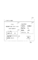
<本実施形態の印刷設定条件表>
図6は、本実施形態における画像形成装置101の記憶装置206に保持される記録紙がジャム発生箇所を通るための各種設定条件をまとめた印刷設定条件表の一例を示した図である。
<Print setting condition table of this embodiment>
FIG. 6 is a diagram illustrating an example of a print setting condition table that summarizes various setting conditions for the recording paper held in the
601は発生区分が給紙部122であるジャムに関する印刷設定条件表、611は発生区分が本体部123であるジャムに関する印刷設定条件表、621は発生区分がフィニッシャ部121であるジャムに関する印刷設定条件表である。
各表において、602、612、622はジャム発生箇所、603、613、623は各印刷設定を表している。 In each table, 602, 612, and 622 represent jam occurrence locations, and 603, 613, and 623 represent print settings.
「デフォルト」と「ジョブ設定値」は、テストジョブの印刷設定の条件としてデフォルトの設定とするか、ジャムが発生したジョブの設定値とするか、を設定するものである。例えば、給紙カセット114で発生したジャムに対するテストジョブは、給紙部の設定がカセット114である必要があり、それ以外の給紙部が設定されていると記録紙が給紙カセット114を通らない。逆に、両面/片面や排紙先などの設定は、いずれの設定値の場合も記録紙は給紙カセット114遅延ジャムの発生箇所を通過する。
“Default” and “job setting value” are used to set whether to use a default setting as a print setting condition of a test job or a setting value of a job in which a jam has occurred. For example, a test job for a jam that has occurred in the
このように、ジョブの印刷設定が異なると記録紙がジャム発生箇所を通らない場合がある。そのため、ジョブの印刷設定によらず、必ず記録紙がジャム発生箇所を通る場合には「デフォルト」としている。また、ジャム発生箇所を通らないことがある場合には、ジャムが発生したジョブと同じ印刷設定とする必要があるため、「ジョブ設定値」となっている。 As described above, when the print setting of the job is different, the recording paper may not pass the jam occurrence portion. For this reason, regardless of the print setting of the job, the default is set when the recording paper always passes through the jammed portion. In addition, when there is a case where the portion where the jam occurs is not passed through, it is necessary to set the same print setting as that of the job where the jam occurs, and therefore, the “job setting value” is set.
本実施例では、サドル搬送パスセンサ滞留ジャムが発生しており、ジャムコードは0x0211A1である。まず、ジャムコードの先頭2桁が“02”であるため発生区分はフィニッシャ部121となり、印刷設定条件表621を参照する。次に、ジャムコードの末尾2桁が“A1”であるため、サドル搬送パスの行を参照すると、各印刷設定は「給紙部:ジョブ設定値、両面/片面:デフォルト、仕上げ/排紙方法:デフォルト、排紙先:デフォルト、ステイプル:デフォルト」であることが分かる。
In this embodiment, a saddle conveyance path sensor stay jam has occurred, and the jam code is 0x0211A1. First, since the first two digits of the jam code are “02”, the occurrence classification is the
<実施例1におけるジャム発生時に取得するジャムコードおよびジョブ属性情報例>
図7は、ジャム発生が発生した時に、ジャム情報取得部402およびジョブ属性情報取得部404によって取得される情報の一例を示した図である。本実施例1においては、記憶装置206へ格納される。
<Jam Code and Job Attribute Information Example Acquired when a Jam Occurs in Embodiment 1>
FIG. 7 is a diagram illustrating an example of information acquired by the jam
701はジャム発生日時である。702はプリンタ部214内のジャムセンサによって検出されるジャムコードである。ジャムが発生したジョブ属性情報として、用紙サイズ703、給紙口704、両面/片面705、仕上げ/排紙方法706、排紙先707、ステイプル708、の各印刷設定情報が格納される。
<実施例1における画像形成装置101の動作フローチャート>
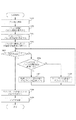
図8は実施例1で画像形成装置101においてプログラムに基づき実現される動作例のフローチャートを示したものである。
<Operation Flowchart of
FIG. 8 shows a flowchart of an operation example realized in the first embodiment based on a program in the
ステップS801において、画像形成装置101はジャム検知部401によってジャム発生を検知する。
In step S <b> 801, the
ステップS802において、画像形成装置101はジャムコードおよびジョブ属性情報をジャム情報取得部402、ジョブ属性情報取得部404により取得し、RAM205へ格納する。
In step S <b> 802, the
ステップS803において、画像形成装置101はジャムコード解析部403によってRAM205に格納されたジャムコードを取得し、マスタデータ出力部406を介してジャムコード一覧を参照してジャム発生箇所を特定する。
In step S <b> 803, the
ステップS804において、画像形成装置101はジョブ生成部405によって、記憶装置206に格納されている印刷設定条件表601、611、621を参照して、各印刷設定を順に行う。テストジョブの印刷設定値はRAM205へ格納していく。
In step S <b> 804, the
ステップS805において、画像形成装置101はジョブ生成部405がテストジョブの全印刷設定項目に対する設定を終了していない場合にはS806へ進む。
In step S805, if the
ステップS806では、テストジョブの各印刷設定項目に関して、ステップS804で参照した印刷設定条件表の値が「ジョブ設定値」の場合にはステップS807へ、「デフォルト」の場合にはステップS808へ進む。 In step S806, for each print setting item of the test job, if the value of the print setting condition table referred to in step S804 is “job setting value”, the process proceeds to step S807, and if it is “default”, the process proceeds to step S808.
ステップS807では、画像形成装置101はRAM205に格納されたジョブ属性情報から印刷設定を取得してテストジョブの設定とする。
In step S <b> 807, the
ステップS808では、テストジョブの設定をデフォルトとする。本実施形態においては、デフォルトの設定を「自動」とする。 In step S808, the test job setting is set as a default. In this embodiment, the default setting is “automatic”.
ここでは、発生したジャムコードが0x0211A1(図7)であるため、印刷設定条件表621を参照する。各印刷設定は、「給紙部:デフォルト、両面/片面:ジョブ設定値、仕上げ/排紙方法:ジョブ設定値、排紙先:ジョブ設定値、ステイプル:ジョブ設定値」である。これら各印刷設定の中で、「ジョブ設定値」のものは取得したジョブ属性情報の値、「デフォルト」のものは「自動」とする。 Here, since the generated jam code is 0x0211A1 (FIG. 7), the print setting condition table 621 is referred to. Each print setting is “paper source: default, duplex / single side: job setting value, finishing / discharge method: job setting value, discharge destination: job setting value, stapling: job setting value”. Among these print settings, the “job setting value” is the value of the acquired job attribute information, and the “default” is “automatic”.
本実施例においては、テストジョブの印刷設定は「給紙部:自動、両面/片面:両面、仕上げ/排紙方法:ソート、排紙先:トレイA、ステイプル:自動」となる。ここで、ステイプルの「自動」設定は、ステイプルなし、とする。 In this embodiment, the print setting of the test job is “paper feeding unit: automatic, duplex / single-sided: duplex, finishing / discharge method: sort, discharge destination: tray A, staple: automatic”. Here, the “automatic” setting for stapling is “no stapling”.
全印刷設定が終了すると、画像形成装置101はステップS809へ進む。
When all print settings are completed, the
ステップS809において、画像形成装置101はRAM205に格納された各印刷設定を取得してテストジョブを生成する。
In step S809, the
ステップS810において、画像形成装置101は生成したジョブを記憶装置206へステップS802で取得したジャム情報と共に格納する。
In step S810, the
<実施例1におけるテストジョブの情報例>
図9は、実施例1において上記ステップS810で記憶装置206へ格納されるテストジョブの情報例を示す図である。
<Example of Test Job Information in Embodiment 1>
FIG. 9 is a diagram illustrating an example of test job information stored in the
901は、テストジョブの情報を示す。902はテストジョブに対応するジャムが発生した日時、903はジャムコードである。904はテストジョブの各印刷設定である。
<実施例1におけるテストジョブ実行指示画面例>
図10は、上記のように記憶装置206へ格納されたテストジョブを実行するためのテストジョブ実行指示画面例を示した図である。
<Example of test job execution instruction screen in embodiment 1>
FIG. 10 is a diagram illustrating an example of a test job execution instruction screen for executing the test job stored in the
1001がテストジョブ実行指示画面である。1002は発生したジャムコード、1003はテストジョブのページ設定、1004は給紙設定、1005は仕上げ設定である。
実行ボタン1006を押下するとテストジョブ実行を開始し、キャンセルボタン1007を押下するとテストジョブを実行せず、終了もしくは前画面へ戻る。
When the
<テストジョブとジャム履歴の紐付け>
テストジョブの情報901では、テストジョブの印刷設定とジャム発生日時・ジャムコードを記憶装置206へ格納している。そのため、ジャム発生日時とジャムコードを参照することにより、テストジョブをジャム履歴と紐付けることも可能である。
<Linking test job and jam history>
In the
<実施例1におけるテストジョブをジャム履歴と紐付けて記録した場合のテストジョブ実行指示画面例>
図11(a)〜(c)は、ジャム履歴と紐付けた場合のテストジョブ実行指示画面例を示した図である。
<Example of test job execution instruction screen when the test job in the first embodiment is recorded in association with the jam history>
FIGS. 11A to 11C are diagrams showing examples of test job execution instruction screens associated with jam histories.
図11(a)はジャム履歴の一覧表示の画面である。1102はジャム履歴の番号、1103が各ジャムの発生日時、1104はジャムコードである。1105は各ジャムに対応したテストジョブの実行を指定するための実行ボタンである。 FIG. 11A shows a list display screen of jam histories. 1102 is a jam history number, 1103 is the occurrence date of each jam, and 1104 is a jam code. Reference numeral 1105 denotes an execution button for designating execution of a test job corresponding to each jam.
更に、上記テストジョブ実行ボタン1105が押下された後に、図11(b)で示す設定確認画面1111を表示してもよい。設定確認画面は、ユーザによってテストジョブの実行を指示するための指示画面である。1112は選択したジャムの情報(ジャム履歴の番号、ジャム発生日時、ジャムコード)、1113はテストジョブのページ設定、1114は給紙設定、1115は仕上げ設定である。OKボタン1116が押下されると、テストジョブの実行を開始し、キャンセルボタン1117が押下されるとテストジョブを実行せず前画面へ戻る。
Furthermore, after the test job execution button 1105 is pressed, a setting confirmation screen 1111 shown in FIG. 11B may be displayed. The setting confirmation screen is an instruction screen for instructing execution of a test job by the user. 1112 is selected jam information (jam history number, jam occurrence date and time, jam code), 1113 is a test job page setting, 1114 is a paper feed setting, and 1115 is a finishing setting. When the
ここで、同じジャムが連続して複数回発生していると、同じ印刷設定のテストジョブが保存される。ジャム履歴表示画面11(c)のように、最新のジャムに関するテストジョブを実行することができるようにしてもよい。1122はジャム履歴の番号、1123はジャムの発生日時、1124はジャムコードである。1125は最新のジャムのテストジョブを実行するための実行ボタンである。
Here, if the same jam occurs a plurality of times in succession, a test job having the same print setting is stored. As shown in the jam history display screen 11 (c), a test job related to the latest jam may be executed. 1122 is a jam history number, 1123 is a jam occurrence date and time, and 1124 is a jam code.
本実施例により、サービスマンが画像形成装置で発生したジャムに対する部品交換などのメンテナンスを行う際のジャム再現テストや、メンテナンス終了後の復旧確認テストを、テスト実施時に設定をすることなく実行することが可能となる。 According to this embodiment, a serviceman performs a jam reproduction test when performing maintenance such as parts replacement for a jam generated in the image forming apparatus and a recovery confirmation test after completion of the maintenance without setting at the time of executing the test. Is possible.
また、本発明においては、テストジョブを生成する際に、ジャムに起因したジョブとは異なるテストジョブを生成すると更に効果を奏する場合がある。例えば、ジャムに起因したジョブが100ページで10部の印刷が指定される場合などもあり、そのジョブをそのまま用いると、復旧確認などをするためには不要な印刷を行ってしまうことになる。更に、ジャムに起因したジョブをそのまま用いても、ジャムの発生箇所を必ずしも用紙が通過しない場合もある。従って、本発明では、ジャムの種類とジャムに起因したジョブの属性情報に基づいて、最適なテストジョブを生成し、特に必要が無い限りはテストジョブ1つにつき1ページの用紙を排紙することを想定している。 In the present invention, when generating a test job, it may be more effective to generate a test job that is different from a job caused by a jam. For example, there are cases where a job due to a jam is designated to print 10 copies per 100 pages. If the job is used as it is, printing is unnecessary for confirmation of restoration. Further, even if a job caused by a jam is used as it is, there is a case where the sheet does not necessarily pass through the location where the jam occurs. Therefore, according to the present invention, an optimum test job is generated based on the type of jam and job attribute information resulting from the jam, and one page of paper is discharged for each test job unless otherwise required. Is assumed.
(実施例2)
複数のジョブを連続で実行ときに発生するジャムでは、1つのジャムが発生すると、画像形成装置101内で同時に複数のジャムセンサがジャムを検知する場合がある。また、1つのジョブの中で、印刷設定の複雑な組み合わせにより給紙口・フィニッシャ処理部など1枚1枚に異なる処理を行う場合に関しても、複数箇所でジャムが検出される場合がある。
(Example 2)
In the case of a jam that occurs when a plurality of jobs are continuously executed, if one jam occurs, a plurality of jam sensors may simultaneously detect the jam in the
このような状況下で、複数のエラー(ジャム)が発生し、それらを復旧した後の復旧確認のための、ジャム発生経路を通過するテストジョブを効率良く生成する場合の動作について説明する。 An operation in the case where a plurality of errors (jams) occur in such a situation and a test job passing through the jam occurrence path for efficiently generating a recovery job after recovering them will be described.
<実施例2におけるジャム発生時に取得するジャムおよびジョブ属性情報例>
実施例1と同様にして記憶装置206へ格納されるジャムおよびジョブ属性情報一例を図12に示す。ここでは、同時刻に3箇所でジャム(ジャム1、ジャム2、ジャム3)が発生している場合の例を示す。
<Example of Jam and Job Attribute Information Acquired when a Jam Occurs in
An example of jam and job attribute information stored in the
1201はジャム発生日時、1202はコントローラ302を介して取得する画像形成装置101のトータルカウンタ、1203はプリンタ部214内のジャムセンサによって検出されるジャムコードである。それぞれのジャムは、ジャムコード一覧501より、ジャム1が給紙カセット114遅延ジャム、ジャム2が給紙カセット115遅延ジャム、ジャム3がサドル搬送パスセンサ滞留ジャム、である。
1201 is a jam occurrence date and time, 1202 is a total counter of the
ジャムが発生したジョブの属性情報として、用紙サイズ1204、給紙口1205、両面/片面1206、仕上げ/排紙方法1207、排紙先1208、ステイプル1209、の各設定情報が格納される。
As the attribute information of the job in which the jam has occurred, setting information of the
発生したジャムの発生日時1201およびジャムが発生したトータルカウンタ1202によって、図12における3つのジャムは同じジョブの中で同時に発生したジャムであることが分かる。
From the
発生した3つのジャムにおいて、ジャム2の用紙サイズ1204と給紙口1205の設定値がジャム1およびジャム3と異なっている。これは、用紙サイズや給紙口の設定をページ毎に設定することが可能であるため、このような設定値となっている。
Of the three jams that occurred, the
<実施例2における画像形成装置101の動作フローチャート>
図13は、実施例2で画像形成装置101においてプログラムに基づき実現される動作例のフローチャートを示した図である。
<Operation Flowchart of
FIG. 13 is a flowchart illustrating an example of an operation realized based on a program in the
ステップS1301において、画像形成装置101はジャム発生検知部401によってジャム発生を検知する。
In step S <b> 1301, the
ステップS1302において、画像形成装置101は図12に示すようなジャムコードおよびジョブの属性情報を取得し、RAM205へ格納する。
In step S <b> 1302, the
ステップS1303において、画像形成装置101はジャムコード解析部403によってRAM205に格納された各ジャムコードからジャム発生箇所を特定する。
In step S <b> 1303, the
ステップS1304において、画像形成装置101はジョブ生成部405によって各ジャムについて記憶装置206に格納されている印刷設定条件表601、611、621を参照する。
In step S <b> 1304, the
ステップS1305において、画像形成装置101はステップS1302でRAM205に格納されたジャムおよびジョブの属性情報のうち、ジャム発生時刻およびジャムが発生したトータルカウンタを比較する。
In step S1305, the
発生したジャムが、異なるジョブで発生していた場合にはステップS1310へ、同じジョブ内で発生していた場合にはステップS1306へ進む。以降のステップで設定されるテストジョブの印刷設定値はRAM205へ格納していく。 If the generated jam has occurred in a different job, the process proceeds to step S1310. If the jam has occurred in the same job, the process proceeds to step S1306. The print setting values of the test job set in the subsequent steps are stored in the RAM 205.
ここでは、同じジョブ内で発生したジャムなのでS1306へ進む。また、発生したジャムは、ジャム1が給紙カセット114遅延ジャム、ジャム2が給紙カセット115遅延ジャム、ジャム3がサドル搬送パスセンサ滞留ジャム、である。
Here, since the jam occurred in the same job, the process proceeds to S1306. The jams that occurred are jam 1 for
ステップS1306において、画像形成装置101はテストジョブに設定すべき全印刷設定項目における比較が終了していない場合には、ステップS1307へ進む。
In step S1306, if the comparison has not been completed for all print setting items to be set in the test job, the
ステップS1307において、画像形成装置101は印刷設定条件表601・611・621を参照し、各ジャムの「ジョブ設定値/デフォルト」を比較する。また、RAM205に格納されたジョブ属性情報から印刷設定を取得し、その設定値を比較する。比較している印刷設定が2つ以上のジャムで「ジョブ設定値」であり、且つジャム間で印刷設定が異なる場合には、ステップS1308へ進む。比較している印刷設定が1つ以下のジャムで「ジョブ設定値」である場合には、ステップS1309へ進む。
In step S 1307, the
ここでは、ジャム1とジャム2において給紙口の設定が「ジョブ設定値」であることが分かる。且つ、それぞれの給紙口の設定値は「カセット114」「カセット115」であるため、ステップS1308へ進む。また、両面/片面・仕上げ/排紙方法・排紙先の設定はジャム3のみで「ジョブ設定値」となっており、設定値は「両面、ソート、トレイA」であるため、ステップS1309へ進む。
Here, it can be seen that the setting of the paper feed port for the jam 1 and the
ステップS1308において、画像形成装置101は、比較している印刷設定が「ジョブ設定値」となっているジャムの印刷設定を全て網羅するために、各設定で1枚ずつ出力されるようなテストジョブの印刷設定を生成する。この場合、記録紙1枚を出力するテストジョブではジャム1およびジャム2の発生箇所を両方通るようなジョブを生成することはできない。そのため、給紙口の設定が「カセット114」と「カセット115」でそれぞれ記録紙1枚を出力するように2つのテストジョブに対して、それぞれ給紙口の設定を行う。
In step S <b> 1308, the
ステップS1309においては、画像形成装置101は、比較している印刷設定が「ジョブ設定値」となっているジャムの印刷設定をテストジョブの設定とする。ここでは、両面/片面の設定はジャム3のみで「ジョブ設定値」となっているので、ジャム3における両面/片面の設定「両面」を上記で生成したテストジョブの両面/片面の設定とする。以下、他の設定に関してもジャム3のみで「ジョブ設定値」となっているので、上記と同様にテストジョブの設定を決定する。ステイプルの設定に関しては、いずれのジャムでも「デフォルト」となっているので、テストジョブの設定は「デフォルト」とする。本実施例ではステイプルの設定のデフォルトはステイプル「なし」とする。
In step S <b> 1309, the
ステップS1311においては、画像形成装置101は、RAM205に格納された各印刷設定を取得してテストジョブを生成する。
In step S1311, the
ステップS1312においては、画像形成装置101は、ステップS1311で生成したテストジョブを記憶装置206へ格納する。
In step S1312, the
<実施例2におけるテストジョブの情報例>
図14は、実施例2において上記ステップS1312で記憶装置206へ格納されるテストジョブの情報例を示す図である。
<Example of Test Job Information in Example 2>
FIG. 14 is a diagram illustrating an example of test job information stored in the
1401は、テストジョブの情報を示す。1402はテストジョブに対応するジャムが発生した日時、1403はジャムコードである。本実施例では3つのジャムが発生しているので、3つのジャムが格納される。1404はテストジョブの各印刷設定である。本実施例では2枚の記録紙を出力するため、1枚毎の印刷設定が格納されている。
<実施例2におけるテストジョブ実行指示画面例>
図15は、上記のように記憶装置206へ格納されたテストジョブを実行するためのテストジョブ実行指示画面の一例を示した図である。
<Example of Test Job Execution Instruction Screen in Second Embodiment>
FIG. 15 is a diagram showing an example of a test job execution instruction screen for executing the test job stored in the
1501は、テストジョブ実行指示画面である。1502は発生したジャムコード、1503は仕上げ設定、1504は給紙設定である。
実行ボタン1505を押下するとテストジョブ実行を開始し、キャンセルボタン1506を押下するとテストジョブを実行せず、終了もしくは前画面へ戻る。
When the execute button 1505 is pressed, test job execution is started, and when the cancel
また、本実施形態では、同じジョブ内で発生した複数ジャムに対して1つのテストジョブを生成するため、ジャム履歴の発生日時に紐付けて記憶装置206へテストジョブを格納してもよい。1511は、ジャム履歴の発生日時に紐付けてテストジョブを格納した場合の、テストジョブ実行指示画面の一例を示した図である。1512は、ジャム履歴の番号、1513はジャム発生日時、1514は発生したジャムコード、1515がテストプリントを実行するための実行ボタンである。
In the present embodiment, in order to generate one test job for a plurality of jams that occur in the same job, the test job may be stored in the
以上、テストジョブを実行する指示をユーザが入力するための画面例を挙げたが、テストジョブ実行指示画面1121のように最新のテストジョブを実行できるようにしてもよい。また、テストジョブ実行指示画面1511においてテストジョブ実行ボタンが押下された後に、設定確認画面1111のような設定を確認する画面を表示してもよい。
The screen example for the user to input an instruction to execute the test job has been described above. However, the latest test job may be executed as in the test job
尚、上記実施例1および実施例2において、ジョブ生成部405が画像形成装置内に実装される必要はなく、他装置(例えば画像形成装置管理サーバなど)にあってもよい。
In the first and second embodiments, the
更に、実施例1および実施例2において、ジャム発生時に取得する情報として、ジャムコード、ジャム発生日時、ジャムが発生したジョブ属性情報(用紙サイズ、給紙口、両面/片面、仕上げ/排紙方法、排紙先、ステイプル)とした。しかしながら、これらの情報に限らず、画像形成装置101で設定可能な印刷設定の情報を全て取得してもよい。また、本実施例では、テストジョブの情報としてジャム発生日時、ジャムコード、テストジョブの印刷設定を保持しているが、これらの情報に限らないことは言うまでも無い。
Further, in the first and second embodiments, as information acquired when a jam occurs, a jam code, a jam occurrence date and time, and job attribute information in which a jam has occurred (paper size, paper feed port, duplex / single side, finishing / discharge method) , Paper discharge destination, staple). However, not limited to these pieces of information, all pieces of print setting information that can be set by the
本実施例により、同一ジョブ内で複数のジャムが発生している場合に、全ジャムの発生箇所を通過するテストジョブを生成することが可能となる。そのため、サービスマンは、同一ジョブ内で発生した複数ジャムに対する再現テスト・復旧確認テストを一つのテストジョブによって実施することが可能となる。 According to the present exemplary embodiment, when a plurality of jams occur in the same job, it is possible to generate a test job that passes through all the jam occurrence points. Therefore, the service person can perform a reproduction test / recovery confirmation test for a plurality of jams occurring in the same job by one test job.
(実施例3)
上記実施例1および実施例2では、ジャムの再現確認のために、記録紙がジャム発生箇所を通るようなテストジョブを生成した。しかし、ジャムの原因箇所とジャム発生箇所は必ずしも一致するものではない。ある場所で記録紙が折れたり曲がったりした場合に、そこよりも後ろの部分でジャムとなることもある。そのため、ジャムの発生箇所を通るようなテストジョブでは不十分なことがある。
(Example 3)
In the first embodiment and the second embodiment, a test job is generated so that the recording paper passes through the jam occurrence location in order to confirm the reproduction of the jam. However, the cause of the jam and the location where the jam occurs do not always match. If the recording paper bends or bends at a certain location, it may become jammed at the rear of the recording paper. For this reason, a test job that passes through the location of the jam may not be sufficient.
そこで、本実施例では、記録紙が折れたり曲がったりしてしまう原因の一つとして挙げられる構成部品の消耗率を参照して、ジャムの発生箇所を通り、且つ消耗率が高い部品をジョブ設定値とするようなテストジョブを生成する場合の動作について説明する。 Therefore, in this embodiment, referring to the consumption rate of the component parts, which can be cited as one of the causes of the recording paper being bent or bent, it is possible to set a job for a part that passes the jam occurrence location and has a high consumption rate. The operation when generating a test job with values will be described.
実施例3では、画像形成装置101の稼動状況を遠隔で管理する画像形成装置管理システムを想定する。このようなシステムでは、管理サーバが画像形成装置101の稼動情報(障害通知やカウンタ値、部品カウンタなど)を収集している。そして、管理サーバが、画像形成装置を構成する構成部品の部品カウンタと部品の推奨寿命などから構成部品の消耗率を算出することができる。
In the third embodiment, an image forming apparatus management system that remotely manages the operation status of the
<実施例3における画像形成装置管理システムの構成例>
図16において、101、1401は顧客のネットワークに設置された画像形成装置である。
<Example of Configuration of Image Forming Apparatus Management System in Embodiment 3>
In FIG. 16,
1602は画像形成装置の管理サーバを示している。管理サーバ1602は、ネットワーク1603上に設置された画像形成装置101、1601及び、図示していない他の複数の画像形成装置とデータの送受信を行っている。管理サーバ1602は受信した画像形成装置の情報を管理している。
ここで、画像形成装置101、1601は同じネットワーク(LAN)1604に接続されているが、これに限らずインターネット1603を介して接続された他のネットワーク(外部のLAN)上に存在してもよい。
Here, the
<実施例3における管理サーバ1602のハードウェア構成例>
図17は、管理サーバ1602のハードウェア構成例を示すブロック図である。
<Example of Hardware Configuration of
FIG. 17 is a block diagram illustrating a hardware configuration example of the
管理サーバ1602は汎用のコンピュータ等で構成されてよい。全体を制御するためのCPU1702と、システム起動に必要なブートプログラムを記憶するための読み出し専用メモリであるROM1703と、CPU1702でプログラムを実行する際に必要とされる作業メモリであるRAM1704とを含む。又、ネットワーク上で通信を行うためのNetwork I/F1705と、表示制御部1706と、入力制御部1707と、CPU1702で実行するプログラムや画像形成装置の稼動情報などを格納する記憶装置1708を含む。
The
これらの各構成要素がシステムバス1701に接続された構成となっている。表示制御部1706には表示デバイス1709が接続され、入力制御部1707には入力デバイス1710、1711が接続されている。管理サーバ1602を管理するオペレータは、これらの入出力デバイスを通じて管理サーバ1602の稼動状態の確認や動作指示を行う。
These components are connected to the
ここで、管理サーバ1602が管理する画像形成装置の情報は、画像形成装置を識別するための画像形成装置識別子(以降IDと呼ぶ)とIDと対応付けて管理される情報がある。ここでIDと対応付けて管理される情報としては、例えば画像形成装置のファームウェアタイプや画像形成装置のタイプなどの画像形成装置基本情報や、エラー・アラーム・ジャムなどの情報、構成部品の消耗率などである。管理サーバ1602は、IDと画像形成装置の各種情報とを対応付けて記憶装置1708に記憶し、管理している。更に、管理サーバ1602は、管理している画像形成装置の画像形成装置識別子の一覧である画像形成装置識別子管理テーブル(図示しない)を保持している。
Here, the information of the image forming apparatus managed by the
また、管理サーバ1602が管理する画像形成装置の異常状態を表す情報として稼働情報に加え、ジャムの情報が含まれている。管理サーバ1602はこの情報を受け取ると、記憶装置1708に逐次格納する。ジャムがある所定の条件(詳述しない)を超えて発生している場合には、ジャムが多発している旨をディスプレイ1709に表示してオペレータに通知する。オペレータは、ディスプレイ1709上の表示内容から画像形成装置の状態を判断し、必要に応じてメンテナンス作業をサービスマンに指示をする。
In addition to the operation information, jam information is included as information indicating an abnormal state of the image forming apparatus managed by the
<実施例3における管理サーバ1602のソフトウェア構成例>
図18は、実施例3における管理サーバ1602のソフトウェア構成例を示すブロック図である。CPU1702はシステム起動時に、ROM1703からシステム起動プログラム(図示せず)を読み出し、動作を開始する。また、各プログラムを記憶装置1708からRAM1704へ読み出し、実行する。
<Example of Software Configuration of
FIG. 18 is a block diagram illustrating a software configuration example of the
1801はOS(オペレーティングシステム)、1802はライブラリである。
1803はアプリケーションであり、アプリケーション1803の一部としてインターネット1403上に設置された画像形成装置101、1401を管理するための画像形成装置管理プログラム1804を含む。
An
1805はWebサーバであり、インターネット1403を介して画像形成装置101とメッセージの送受信を行う。Webサーバ1805上には、印刷設定対応表生成プログラム1806が存在している。印刷設定対応表生成プログラム1806は、画像形成装置101から受信したジャム情報と、記憶装置1708に格納された画像形成装置101に関する部品消耗率を参照し、部品消耗率によるテストジョブの設定対応表を生成する。
A
<実施例3における画像形成装置101のハードウェア構成例>
図2に示した画像形成装置101の主要部構成を示したブロック図において、ROM204に格納されるプログラムは、画像形成装置の制御プログラム、ジャムコードに応じたテストジョブを生成するテストジョブ生成プログラム305である。本実施形態では、これらのプログラムに加えて画像形成装置監視プログラム(図示せず)が格納される。
<Example of Hardware Configuration of
In the block diagram showing the main configuration of the
尚、画像形成装置監視プログラムは本実施例では、画像形成装置に組み込まれているが、ネットワーク経由で画像形成装置から情報を取得するように構成された画像形成装置とは別の監視装置に組み込まれていてもよいことはいうまでもない。 In this embodiment, the image forming apparatus monitoring program is incorporated in the image forming apparatus. However, the image forming apparatus monitoring program is incorporated in a monitoring apparatus different from the image forming apparatus configured to acquire information from the image forming apparatus via the network. Needless to say, it may be.
また、CPU207で実行される画像形成装置監視プログラムにより、記憶装置206内のカウンタ値や稼働ログなどの稼動情報やジャムなどの障害情報を読み出す。そして、画像形成装置のステータス情報として管理サーバ1602へ、Network I/F202を介して送信する。
Further, operation information such as a counter value and an operation log in the
<実施例3における画像形成装置101ソフトウェア構成例>
図3に示した画像形成装置101のソフトウェア構成例に加えて、アプリケーション304の一部としてWebサーバ(図示せず)と、画像形成装置監視プログラム(図示せず)を含む。Webサーバは、インターネット1403を介して管理サーバ1602とメッセージの送受信を行う。
<Software Configuration Example of
In addition to the software configuration example of the
画像形成装置監視プログラムは、コントローラ302を介して画像形成装置の各種情報を取得する。画像形成装置監視プログラムは定期的にファームウェアタイプや印刷枚数、部品消耗度に関する情報を取得し、管理サーバ1602に送信する。また、エラー・アラーム・ジャムや、トナー切れ間近・ドアオープン等といったステータス情報は発生を検知すると管理サーバ1602に送信する。画像形成装置監視プログラムが定期的、発生時に送信する情報は上記に限定するものではないことはいうまでもない。
The image forming apparatus monitoring program acquires various types of information on the image forming apparatus via the controller 302. The image forming apparatus monitoring program periodically acquires information on the firmware type, the number of printed sheets, and the degree of component consumption, and transmits the information to the
<実施例3における画像形成装置101の機能を示すブロック図>
図19は、画像形成装置101においてテストジョブ生成プログラム305に関連する機能を示すブロック図である。実施例1および2における画像形成装置101の機能を示すブロック図(図2)との差異部分のみ説明する。
<Block Diagram showing Functions of
FIG. 19 is a block diagram illustrating functions related to the test
通信I/F部1901は、Network I/F202を介して管理サーバ1602とメッセージの送受信を行う。
The communication I /
ジョブ生成部405は、取得したジャムコードおよびジョブ属性情報を管理サーバ1602への送信を通信I/F部1901に依頼する。また、通信I/F部1901が管理サーバ1602から受信したテストジョブの設定依存性対応表を受け取る。このようにして受け取ったテストジョブの設定依存性対応表と、マスタデータ記憶部407に格納された印刷設定条件表を元に、テストジョブを生成する。
The
<実施例3における画像形成装置101が管理サーバ1602へ送信する送信データ例>
図20は、画像形成装置101でジャムが発生した時に、テストジョブ生成プログラム305が管理サーバ1602へ送信する送信データの一例を示した図である。管理サーバ1602はNetwork I/F1705を介してデータを受信する。
<Example of Transmission Data Transmitted by
FIG. 20 is a diagram illustrating an example of transmission data that the test
尚、図20には、本実施形態に関連があるデータのみを示している。また、メッセージの送受信には、HTTP(Hyper Text Transfer Protocol)を利用する。 FIG. 20 shows only data related to this embodiment. In addition, HTTP (Hyper Text Transfer Protocol) is used for sending and receiving messages.
2001が送信データ全体である。2002は画像形成装置101を特定するための情報(IDなど)である。2003はジャム発生日時、2004はジャム発生時にコントローラ302を介して取得されるトータルカウンタ、2005はジャムコードである。
ここで発生したジャム(0x010107)は、ジャムコード一覧501より、定着排紙遅延ジャムであることがわかる。
It can be seen from the
また、ジャムが発生したジョブの属性情報として、用紙サイズ2006、給紙口2007、両面/片面2008、仕上げ/排紙方法2009、排紙先1810、ステイプル1811、の各設定情報が格納される。
Further, setting information of a
<実施例3における管理サーバ1602が保持する設定−使用部品対応表例>
図21は、実施例3において管理サーバ1602の記憶装置1708に格納されている設定−使用部品対応表の一例を示した図である。
<Setting-Use Component Correspondence Table Example Held by
FIG. 21 is a diagram illustrating an example of the setting-use component correspondence table stored in the
2101は設定−使用部品対応表の全体を表している。
2102は画像形成装置101の本体区分、2103は各本体区分2102に関係する印刷設定の値、2104は各印刷設定2103によって使用される部品の名前、2105は各部品の場所を示すポジションマーカである。
2102 is a main body section of the
例えば、本体区分2102の給紙部で使用される部品は、設定2103の値によって異なる。給紙部の設定に関わらずジョブ設定値部品は、設定2103が「全設定」の「給紙搬送ローラ1」「レジストロール」(いずれも図示せず)である。給紙部の設定が“カセット114”の場合にジョブ設定値部品は、設定2103が「全設定」と「カセット114」の「給紙搬送ローラ1」「レジストロール」「カセット114給紙ローラ」「カセット114搬送ローラ」(いずれも図示せず)である。
For example, the parts used in the paper feed unit of the
このように設定−使用部品対応表2101を参照することによって、ジャムが発生したジョブ設定情報から使用した部品が分かる。 By referring to the setting / used parts correspondence table 2101 in this way, the used parts can be found from the job setting information in which a jam has occurred.
<実施例3における管理サーバ1602が保持する消耗率の参照結果一覧例>
図22は、実施例3において管理サーバ1602上の印刷設定対応表生成プログラム1806が部品の消耗率を参照した結果一覧例を示す図である。この表は、管理サーバ1602のRAM1704に格納される。
<Example of List of Consumption Rates Referenced by
FIG. 22 is a diagram illustrating a result list example in which the print setting correspondence
また、参照する部品は記録紙が給紙されてからジャムが発生するまでに使用した部品とする。テストジョブ設定条件表生成プログラム1606は画像形成装置101からの受信データ2001および上記設定−使用部品対応表1901より、消耗率を参照すべき部品の一覧を生成する。
Further, the parts to be referred to are the parts used after the recording paper is fed until the jam occurs. The test job setting condition table generation program 1606 generates a list of components whose consumption rate should be referred to from the received
2201は部品の消耗率を参照した結果全体を示す。
2202は画像形成装置101の本体区分、2203は各本体区分2202に関係する受信データ2201の設定、2204は使用される部品の名前、2205は各部品の場所を示すポジションマーカ、2206が部品の消耗率である。
2202 is a main body section of the
消耗率が閾値を超えている部品がある場合に、テストジョブの印刷設定をその部品が使用されるような設定値にする。そのため、該当する部品がある設定値の時にのみ使用される場合、テストジョブの印刷設定をジャムが発生したジョブと同じ設定にする。 When there is a part whose wear rate exceeds the threshold, the print setting of the test job is set to a setting value that uses the part. For this reason, when the corresponding part is used only at a certain set value, the print setting of the test job is set to the same setting as that of the job in which the jam has occurred.
上記のように印刷設定対応表生成プログラム1806はテストジョブの各印刷設定を、部品消耗率から「デフォルト」とするか、ジャムが発生した「ジョブの設定値」とするかを決定する。その結果を画像形成装置101へ送信することにより、テストジョブ生成プログラム305が、ジャム発生箇所と消耗率が高い部品に関連した印刷設定の設定値をもつテストジョブを生成することができる。
As described above, the print setting correspondence
尚、本実施例では部品の消耗率の閾値を85%とする。 In this embodiment, the threshold for the wear rate of parts is set to 85%.
<実施例3における画像形成装置101が管理サーバ1602から受信する受信データ例>
図23は、実施例3において画像形成装置101が管理サーバ1602から受信する受信データの一例を示す図である。画像形成装置101はNetwork I/F202を介してデータを受信し、RAM205へ格納する。
<Example of Received Data Received from
FIG. 23 is a diagram illustrating an example of received data that the
2301は、受信データ全体を表す。2302は、画像形成装置101を特定するための情報(IDなど)である。2303はジャム発生日時、2304はジャムコードである。2305は印刷設定対応表である。印刷設定として、給紙口2306、両面/片面2307、仕上げ/排紙方法2308、排紙先2309、ステイプル2110の値が格納される。
2301 represents the entire received data. 2302 is information (ID or the like) for specifying the
<実施例3における画像形成装置101の動作フローチャート>
図24は、実施例3で画像形成装置101においてプログラムに基づき実現される動作例のフローチャートを示した図である。
<Operation Flowchart of
FIG. 24 is a flowchart illustrating an example of an operation realized based on a program in the
まず、ステップS2401において、ジャム検知部401はジャム発生検知部401によってジャム発生を検知する。
First, in step S <b> 2401, the
次に、ステップS2402において、ジャム情報取得部402とジョブ属性情報取得部404は、記憶装置206からジャムコードおよびジョブ属性情報を取得し、RAM205へ格納する。
In step S2402, the jam
ステップS2403において、画像形成装置101においてRAM205に格納されたジャムコードおよびジョブ属性情報を取得して、画像形成装置101のIDを付加して管理サーバ1602への送信データ2001を生成する。生成した送信データ2001はRAM205へ格納する。RAM205に格納した送信データ2001は、Network I/F202を介して管理サーバ1602へ送信する。
In step S2403, the
ステップS2404において、通信I/F部1901は、Network I/F202を介して管理サーバ1602から受信データ2101を受信し、RAM205へ格納する。RAM205へ格納した受信データ2301から、デバイスID2102・ジャムの発生日時2103・ジャムコード2104を取得し、テストジョブ生成の対象となっているジャムに関する受信データであることを確認する。
In step S2404, the communication I /
ステップS2405において、ジャムコード解析部403はRAM205に格納されたジャムコードからジャム発生箇所を特定する。本実施例で発生したジャム1805は、定着排紙遅延ジャム(0x010107)である。
In step S <b> 2405, the jam
ステップS2405において、ジョブ生成部405はテストジョブの各印刷設定項目に関して、印刷設定条件表601・611・621の値と印刷設定対応表2105の値を比較する。全印刷設定の比較が終了すると、ステップS2412へ進む。全印刷設定の比較が終了していない場合は、ステップS2408へ進む。
In step S2405, the
ステップS2408において、ジョブ生成部405は印刷設定条件表601・602・603を参照する。印刷設定条件表で該当する印刷設定が「デフォルト」の場合はステップS2409へ、「ジョブの設定値」の場合にはステップS2410へ進む。例えば、給紙口の設定は、印刷設定条件表611より「デフォルト」であることがわかる。そのため、ステップS2409へ進む。
In
ステップS2409では、ジョブ生成部405はRAM205へ格納した受信データ2301から印刷設定対応表2105を取得し、該当する印刷設定を参照する。印刷設定が「デフォルト」の場合にはステップS2411へ、「ジョブの設定値」の場合にはステップS2410へ進む。ここで、給紙口の設定は、印刷設定対応表2105より「ジョブの設定値」であることがわかる。そのため、ステップS2410へ進む。
In step S2409, the
ステップS2410では、ジョブ生成部405は、RAM205へ格納されたジャムが発生したジョブ属性から各印刷設定を取得して、テストジョブの印刷設定としてRAM205へ格納する。
In step S2410, the
ステップS2411において、ジョブ生成部405は、テストジョブの印刷設定を「デフォルト」とし、RAM205へ格納する。
In
ステップS2412において、ジョブ生成部405は、RAM205に格納されたテストジョブの印刷設定を元に、テストジョブを生成する。
In step S 2412, the
ステップS2413において、ステップS2412で生成したテストジョブは、ジョブ入出力部408を介して記憶装置206で格納される。
In
<実施例3における管理サーバ1602の動作フローチャート>
図25は、実施例3で管理サーバ1602においてCPUがプログラムを実行することで実現する動作例のフローチャートを示した図である。
<Operation Flowchart of
FIG. 25 is a diagram illustrating a flowchart of an operation example realized by the CPU executing a program in the
ステップS2501において、管理サーバ1602は、Network I/F1705を介して画像形成装置101から、送信データ2001を受信し、RAM1704へ格納する。
In step S2501, the
ステップS2502において、記憶装置1708に格納された設定−使用部品対応表2101を取得する。また、RAM1704からジャムコード1805と各印刷設定1807〜1811を取得する。
In step S2502, the setting-use component correspondence table 2101 stored in the
ステップS2503において、ステップS2502で取得した情報から消耗率を参照すべき部品の一覧2201を生成し、RAM1704へ格納する。このとき、消耗率2206に値は格納されていない。
In step S2503, a
ステップS2504において、各印刷設定を「デフォルト」とするか「ジョブの設定値」とするかをまとめた印刷設定対応表を生成する。全印刷設定が終わるとステップS2510へ進む。 In step S2504, a print setting correspondence table in which each print setting is set to “default” or “job setting value” is generated. When all the print settings are completed, the process proceeds to step S2510.
ステップS2505において、記憶装置1708から該当する部品の消耗率を取得し、RAM1704へ格納する。
In step S2505, the wear rate of the corresponding part is acquired from the
ステップS2506において、ステップS2505で取得した消耗率が85%以上である場合にステップS2507へ進む。消耗率が85%未満の場合にステップS2504へ戻る。 In step S2506, if the wear rate acquired in step S2505 is 85% or more, the process proceeds to step S2507. If the consumption rate is less than 85%, the process returns to step S2504.
ステップS2507において、消耗率が85%以上である全ての部品が、印刷設定によらず必ず使用されるものであれば、ステップS2509へ進む。消耗率が85%以上である部品の中に、印刷設定によって使用されない部品が含まれている場合にはステップS2508へ進む。 If it is determined in step S2507 that all parts having a consumption rate of 85% or more are always used regardless of print settings, the process advances to step S2509. If the parts with a consumption rate of 85% or more include parts that are not used due to print settings, the process advances to step S2508.
ステップS2508において、管理サーバ1602は印刷設定対応表内で該当する印刷設定を「ジョブの設定値」としてRAM1704へ格納する。
In step S2508, the
ステップS2509において、管理サーバ1602は印刷設定対応表内で該当する印刷設定を「デフォルト」としてRAM1704へ格納する。
In step S2509, the
ステップS2510において、管理サーバ1602は、RAM1704に格納された印刷設定対応表を元にデータ2301を生成し、Network I/F1705を介して画像形成装置101へ送信する。
In step S2510, the
<実施例3におけるテストジョブの情報例>
図26は、実施例3において上記ステップS2412で記憶装置206へ格納されるテストジョブの情報例を示す図である。
<Example of Test Job Information in Embodiment 3>
FIG. 26 is a diagram illustrating an example of test job information stored in the
2601は、テストジョブの情報を示す。2602はテストジョブに対応するジャムが発生した日時、2603はジャムコードである。本実施例では3つのジャムが発生しているので、3つのジャムが格納される。2604はテストジョブの各印刷設定である。
<実施例3におけるテストジョブ実行指示画面例>
図27は、実施例3におけるテストジョブ実行指示画面例を示す図である。
<Example of Test Job Execution Instruction Screen in Embodiment 3>
FIG. 27 is a diagram illustrating an example of a test job execution instruction screen according to the third embodiment.
2701は、テストジョブ実行指示画面である。2702は、ジャム発生日時・ジャムコードなどのジャムに関する情報が表示される。2703は、テストジョブのページ設定である。2704は、テストジョブの給紙設定であり、2705は、テストジョブの仕上げ設定である。
2706は実行ボタンである。実行ボタン2706が押下されると、画像形成装置101はテストジョブを実行する。
テストジョブ実行指示画面は、2701に示す画面に限らない。図10、図11および図15に示すようなテストジョブ実行指示画面によってユーザの入力を受信し、実行されてもよい。
The test job execution instruction screen is not limited to the
尚、実施例3では実施例1および実施例2と同様にジョブ生成部405が画像形成装置内に実装される必要はなく、他装置(例えば管理サーバ1602)にあってもよい。
In the third embodiment, as in the first and second embodiments, the
また、実施例3では部品の消耗率の閾値を85%としたが、本特許の効果を実現することが可能な値の範囲であれば任意の値でよい。ユーザの入力によって設定できるようにしてもよい。 In the third embodiment, the threshold of the wear rate of parts is 85%. However, any value may be used as long as the value can achieve the effect of this patent. It may be set by user input.
本実施例により、ジャム発生箇所と消耗率が高い部品を使用するようなテストジョブを生成することが可能となる。これによって、部品消耗率が高いことによってサービスマンが部品を交換した場合に、ジャム復旧確認テストを容易に行うことが可能となる。 According to the present embodiment, it is possible to generate a test job that uses a part where a jam occurs and a part with a high consumption rate. This makes it possible to easily perform a jam recovery confirmation test when a serviceman replaces a part due to a high part consumption rate.
[他の実施の形態]
以上、様々な実施形態を詳述したが、本発明は、複数の機器から構成されるシステムに適用してもよいし、また、一つの機器からなる装置に適用してもよい。例えば、プリンタ、ファクシミリ、PC、サーバとクライアントとを含むコンピュータシステムなどの如くである。
[Other embodiments]
Although various embodiments have been described in detail above, the present invention may be applied to a system constituted by a plurality of devices, or may be applied to an apparatus constituted by one device. For example, a computer system including a printer, a facsimile, a PC, a server, and a client.
本発明は、前述した実施形態の各機能を実現するソフトウェアプログラムを、システム若しくは装置に対して直接または遠隔から供給し、そのシステム等に含まれるコンピュータが該供給されたプログラムコードを読み出して実行することによっても達成される。 The present invention supplies a software program that implements the functions of the above-described embodiments directly or remotely to a system or apparatus, and a computer included in the system reads and executes the supplied program code. Can also be achieved.
従って、本発明の機能・処理をコンピュータで実現するために、情報処理装置にインストールされるプログラムコード自体も本発明を実現するものである。つまり、上記機能・処理を実現するためのコンピュータプログラム自体も本発明の一つである。 Accordingly, the program code itself installed in the information processing apparatus in order to implement the functions and processing of the present invention with a computer also implements the present invention. That is, the computer program itself for realizing the functions and processes is also one aspect of the present invention.
その場合、プログラムの機能を有していれば、オブジェクトコード、インタプリタにより実行されるプログラム、OSに供給するスクリプトデータ等、プログラムの形態を問わない。 In this case, the program may be in any form as long as it has a program function, such as an object code, a program executed by an interpreter, or script data supplied to the OS.
プログラムを供給するための記録媒体としては、例えば、フレキシブルディスク、ハードディスク、光ディスク、光磁気ディスク、MO、CD−ROM、CD−R、CD−RWなどがある。また、記録媒体としては、磁気テープ、不揮発性のメモリカード、ROM、DVD(DVD−ROM,DVD−R)などもある。 Examples of the recording medium for supplying the program include a flexible disk, hard disk, optical disk, magneto-optical disk, MO, CD-ROM, CD-R, and CD-RW. Examples of the recording medium include a magnetic tape, a non-volatile memory card, a ROM, a DVD (DVD-ROM, DVD-R), and the like.
また、プログラムは、クライアントの情報処理装置のブラウザを用いてインターネットのホームページからダウンロードしてもよい。すなわち、該ホームページから本発明のコンピュータプログラムそのもの、もしくは圧縮され自動インストール機能を含むファイルをハードディスク等の記録媒体にダウンロードしてもよいのである。また、本発明のプログラムを構成するプログラムコードを複数のファイルに分割し、それぞれのファイルを異なるホームページからダウンロードすることによっても実現可能である。つまり、本発明の機能処理をコンピュータで実現するためのプログラムファイルを複数のユーザに対してダウンロードさせるWWWサーバも、本発明の構成要件となる場合がある。 Further, the program may be downloaded from a homepage on the Internet using a browser of the information processing apparatus of the client. That is, the computer program itself of the present invention or a compressed file including an automatic installation function may be downloaded from the home page to a recording medium such as a hard disk. It can also be realized by dividing the program code constituting the program of the present invention into a plurality of files and downloading each file from a different homepage. That is, a WWW server that allows a plurality of users to download a program file for realizing the functional processing of the present invention on a computer may be a constituent requirement of the present invention.
また、本発明のプログラムを暗号化してCD−ROM等の記憶媒体に格納してユーザに配布してもよい。この場合、所定条件をクリアしたユーザにのみ、インターネットを介してホームページから暗号化を解く鍵情報をダウンロードさせ、その鍵情報で暗号化されたプログラムを復号して実行し、プログラムを情報処理装置にインストールしてもよい。 Further, the program of the present invention may be encrypted and stored in a storage medium such as a CD-ROM and distributed to users. In this case, only the user who has cleared the predetermined condition is allowed to download the key information to be decrypted from the homepage via the Internet, decrypt the program encrypted with the key information, and execute the program. May be installed.
また、コンピュータが、読み出したプログラムを実行することによって、前述した実施形態の機能が実現されてもよい。なお、そのプログラムの指示に基づき、コンピュータ上で稼動しているOSなどが、実際の処理の一部または全部を行ってもよい。もちろん、この場合も、前述した実施形態の機能が実現され得る。 Further, the functions of the above-described embodiments may be realized by the computer executing the read program. Note that an OS or the like running on the computer may perform part or all of the actual processing based on the instructions of the program. Of course, also in this case, the functions of the above-described embodiments can be realized.
さらに、記録媒体から読み出されたプログラムが、情報処理装置に挿入された機能拡張ボードや情報処理装置に接続された機能拡張ユニットに備わるメモリに書き込まれてもよい。そのプログラムの指示に基づき、その機能拡張ボードや機能拡張ユニットに備わるCPUなどが実際の処理の一部または全部を行ってもよい。このようにして、前述した実施形態の機能が実現されることもある。 Furthermore, the program read from the recording medium may be written in a memory provided in a function expansion board inserted into the information processing apparatus or a function expansion unit connected to the information processing apparatus. Based on the instructions of the program, a CPU or the like provided in the function expansion board or function expansion unit may perform part or all of the actual processing. In this way, the functions of the above-described embodiments may be realized.
101 画像形成装置
501 ジャムコード一覧
601、610、620 印刷設定条件表
101
Claims (10)
画像形成装置において実行されたジョブの属性情報を記憶する記憶手段と、
前記画像形成装置におけるジャムを検出する検出手段と、
前記検出手段で検出されたジャムの箇所と、前記ジャムに対応する前記記憶手段に記憶されたジョブの属性情報と、前記管理サーバから取得する構成部品の消耗度に応じた情報とに基づく印刷設定が設定されたテストジョブを生成する生成手段とを備え、
前記生成手段は、前記ジャムに対応するジョブの属性情報として記憶された複数の印刷設定の中で、前記ジャムの箇所に関連する一部の印刷設定が設定されたテストジョブを生成することを特徴とする画像形成装置。 An image forming apparatus connected via a network to a management server that collects operation information of the image forming apparatus and manages the degree of wear of components constituting the image forming apparatus,
Storage means for storing attribute information of a job executed in the image forming apparatus;
Detecting means for detecting a jam in the image forming apparatus;
And location of the jam detected by the detecting means, the attribute information of the job stored in the storage means corresponding to the jam, print settings based on the information corresponding to the degree of wear of components acquired from the management server Generating means for generating a test job set with
The generation unit generates a test job in which a part of print settings related to the jam location are set among a plurality of print settings stored as attribute information of a job corresponding to the jam. An image forming apparatus.
前記生成手段は、前記複数箇所で検出されたジャムに対応する前記記憶手段に記憶されたジョブの属性情報に基づく印刷設定が設定されたテストジョブを生成することを特徴とする請求項1または請求項2に記載の画像形成装置。 When a jam is detected at a plurality of locations of the image forming apparatus by the detection unit,
Said generating means, according to claim 1 or, characterized in that pre-Symbol print settings based on the attribute information of the job stored in the storage means corresponding to the detected jam in a plurality of locations to generate a test job set The image forming apparatus according to claim 2.
画像形成装置において実行されたジョブの属性情報を記憶する記憶工程と、A storage step of storing attribute information of a job executed in the image forming apparatus;
前記画像形成装置におけるジャムを検出する検出工程と、A detection step of detecting a jam in the image forming apparatus;
前記検出工程で検出された前記ジャムの箇所と、前記ジャムに対応する前記記憶工程で記憶されたジョブの属性情報、前記管理サーバから取得する構成部品の消耗度に応じた情報とに基づく印刷設定が設定されたテストジョブを生成する生成工程とを備え、Print setting based on the location of the jam detected in the detection step, attribute information of the job stored in the storage step corresponding to the jam, and information corresponding to the degree of consumption of the component acquired from the management server And a generation process for generating a test job set with
前記生成工程において、前記ジャムに対応するジョブの属性情報として記憶された複数の印刷設定の中で、前記ジャムの箇所に関連する一部の印刷設定が設定されたテストジョブを生成することを特徴とすることを特徴とする情報処理方法。In the generating step, a test job in which a part of print settings related to the jam location is set among a plurality of print settings stored as attribute information of the job corresponding to the jam is generated. An information processing method characterized by:
前記生成工程において、前記複数箇所で検出されたジャムに対応する前記記憶工程で記憶されたジョブの属性情報に基づく印刷設定が設定されたテストジョブを生成することを特徴とする請求項6または請求項7に記載の情報処理方法。7. The test job according to claim 6, wherein in the generation step, a test job in which print settings are set based on job attribute information stored in the storage step corresponding to jams detected at the plurality of locations is generated. Item 8. The information processing method according to Item 7.
Priority Applications (2)
| Application Number | Priority Date | Filing Date | Title |
|---|---|---|---|
| JP2008052088A JP5159370B2 (en) | 2008-03-03 | 2008-03-03 | Image forming apparatus and information processing method |
| US12/396,985 US8218168B2 (en) | 2008-03-03 | 2009-03-03 | Image forming apparatus and information processing method |
Applications Claiming Priority (1)
| Application Number | Priority Date | Filing Date | Title |
|---|---|---|---|
| JP2008052088A JP5159370B2 (en) | 2008-03-03 | 2008-03-03 | Image forming apparatus and information processing method |
Publications (3)
| Publication Number | Publication Date |
|---|---|
| JP2009208300A JP2009208300A (en) | 2009-09-17 |
| JP2009208300A5 JP2009208300A5 (en) | 2011-04-07 |
| JP5159370B2 true JP5159370B2 (en) | 2013-03-06 |
Family
ID=41012967
Family Applications (1)
| Application Number | Title | Priority Date | Filing Date |
|---|---|---|---|
| JP2008052088A Expired - Fee Related JP5159370B2 (en) | 2008-03-03 | 2008-03-03 | Image forming apparatus and information processing method |
Country Status (2)
| Country | Link |
|---|---|
| US (1) | US8218168B2 (en) |
| JP (1) | JP5159370B2 (en) |
Families Citing this family (9)
| Publication number | Priority date | Publication date | Assignee | Title |
|---|---|---|---|---|
| JP5811515B2 (en) * | 2010-03-30 | 2015-11-11 | セイコーエプソン株式会社 | Recording device |
| JP2013022756A (en) * | 2011-07-15 | 2013-02-04 | Canon Inc | Image forming apparatus, control method, and program |
| JP6485989B2 (en) * | 2011-12-26 | 2019-03-20 | キヤノン株式会社 | Image forming apparatus and control method thereof |
| JP6102327B2 (en) * | 2013-02-21 | 2017-03-29 | 株式会社リコー | Electronic device, information processing system and program |
| JP6346818B2 (en) * | 2014-07-31 | 2018-06-20 | 理想科学工業株式会社 | Image forming apparatus and image forming system |
| JP6503690B2 (en) * | 2014-10-27 | 2019-04-24 | 富士ゼロックス株式会社 | Information processing system and program |
| JP6201001B1 (en) * | 2016-04-28 | 2017-09-20 | 株式会社Pfu | Image processing apparatus, image processing method, and program |
| JP2020038275A (en) * | 2018-09-04 | 2020-03-12 | コニカミノルタ株式会社 | Job reproduction method and job reproduction program |
| KR20200088692A (en) * | 2019-01-15 | 2020-07-23 | 휴렛-팩커드 디벨롭먼트 컴퍼니, 엘.피. | Method for setting option based on installation environment |
Family Cites Families (13)
| Publication number | Priority date | Publication date | Assignee | Title |
|---|---|---|---|---|
| JPH05270622A (en) * | 1992-03-24 | 1993-10-19 | Sharp Corp | Jamming control device |
| JP3509048B2 (en) * | 1996-07-10 | 2004-03-22 | 株式会社リコー | Image forming device |
| JPH1039686A (en) * | 1996-07-23 | 1998-02-13 | Canon Inc | Image recording device and reproducing method for jam cause |
| JPH1191217A (en) | 1997-09-24 | 1999-04-06 | Fuji Xerox Co Ltd | Printing processor |
| JP4038325B2 (en) * | 2000-06-26 | 2008-01-23 | シャープ株式会社 | Abnormal display device for image forming apparatus |
| JP2002351170A (en) * | 2001-05-29 | 2002-12-04 | Canon Inc | Image forming device with jam diagnostic mode |
| JP2004061739A (en) * | 2002-07-26 | 2004-02-26 | Canon Finetech Inc | Image forming apparatus |
| JP2005014354A (en) * | 2003-06-25 | 2005-01-20 | Canon Inc | Image forming apparatus and its management system |
| JP4182114B2 (en) * | 2005-06-23 | 2008-11-19 | キヤノン株式会社 | Image forming apparatus monitoring system, monitoring method and program |
| JP4199790B2 (en) * | 2006-09-01 | 2008-12-17 | シャープ株式会社 | Image processing device |
| US7884959B2 (en) * | 2006-10-24 | 2011-02-08 | Xerox Corporation | Printing system and method of operating same |
| JP5216430B2 (en) * | 2008-06-16 | 2013-06-19 | 理想科学工業株式会社 | Printing device |
| JP4894883B2 (en) * | 2009-04-30 | 2012-03-14 | ブラザー工業株式会社 | Printing system, printing apparatus and printer driver |
-
2008
- 2008-03-03 JP JP2008052088A patent/JP5159370B2/en not_active Expired - Fee Related
-
2009
- 2009-03-03 US US12/396,985 patent/US8218168B2/en not_active Expired - Fee Related
Also Published As
| Publication number | Publication date |
|---|---|
| US20090219572A1 (en) | 2009-09-03 |
| JP2009208300A (en) | 2009-09-17 |
| US8218168B2 (en) | 2012-07-10 |
Similar Documents
| Publication | Publication Date | Title |
|---|---|---|
| JP5159370B2 (en) | Image forming apparatus and information processing method | |
| JP4182114B2 (en) | Image forming apparatus monitoring system, monitoring method and program | |
| JP5300332B2 (en) | Network device, workflow processing system, and workflow processing method | |
| JP4137096B2 (en) | Image data search system, image data search device, image data search method, computer program, and storage medium | |
| JP5489643B2 (en) | Management system, image forming apparatus, and method thereof | |
| JP5142578B2 (en) | Image forming apparatus and information processing method thereof | |
| JP5016940B2 (en) | Image forming apparatus monitoring apparatus, monitoring system, control method therefor, program, and storage medium | |
| JP7039377B2 (en) | Information processing device, control method of information processing device, and program | |
| US20190364169A1 (en) | Image forming apparatus, image forming system, and error notification method | |
| JP2007140786A (en) | Controller unit, its control method, and printing system | |
| JP2006301975A (en) | Information processing device, information processing method and program | |
| JP2006205671A (en) | Information processor and its controlling method | |
| JP2020160230A (en) | Image formation apparatus and control method thereof | |
| US9832340B2 (en) | Image forming apparatus and method of performing error notification and error recovery functions in image forming apparatus | |
| JP4564823B2 (en) | PRINT CONTROL DEVICE, PRINT CONTROL METHOD, PROGRAM, AND STORAGE MEDIUM | |
| US7734851B2 (en) | Information processing apparatus, management apparatus, and communication method | |
| JP2009042840A (en) | Image forming apparatus | |
| JP4408927B2 (en) | Image forming apparatus and information processing method | |
| JP2010287108A (en) | Image processing apparatus | |
| JP4912211B2 (en) | Image processing apparatus, control method therefor, program, and storage medium | |
| JP2008102284A (en) | Image forming apparatus, control method, and computer program | |
| US10924617B2 (en) | Image forming system, portable terminal, and error notification method | |
| JP2009260683A (en) | Image processing apparatus | |
| JP2006092010A (en) | Image forming apparatus, maintenance managing system, and maintenance managing method | |
| JP2005135333A (en) | Program monitoring device, program monitoring method, program, storage medium, and information acquisition system |
Legal Events
| Date | Code | Title | Description |
|---|---|---|---|
| RD04 | Notification of resignation of power of attorney |
Free format text: JAPANESE INTERMEDIATE CODE: A7424 Effective date: 20100201 |
|
| RD01 | Notification of change of attorney |
Free format text: JAPANESE INTERMEDIATE CODE: A7421 Effective date: 20100630 |
|
| A521 | Request for written amendment filed |
Free format text: JAPANESE INTERMEDIATE CODE: A523 Effective date: 20110218 |
|
| A621 | Written request for application examination |
Free format text: JAPANESE INTERMEDIATE CODE: A621 Effective date: 20110218 |
|
| A977 | Report on retrieval |
Free format text: JAPANESE INTERMEDIATE CODE: A971007 Effective date: 20120725 |
|
| A131 | Notification of reasons for refusal |
Free format text: JAPANESE INTERMEDIATE CODE: A131 Effective date: 20120731 |
|
| A521 | Request for written amendment filed |
Free format text: JAPANESE INTERMEDIATE CODE: A523 Effective date: 20121001 |
|
| TRDD | Decision of grant or rejection written | ||
| A01 | Written decision to grant a patent or to grant a registration (utility model) |
Free format text: JAPANESE INTERMEDIATE CODE: A01 Effective date: 20121113 |
|
| A61 | First payment of annual fees (during grant procedure) |
Free format text: JAPANESE INTERMEDIATE CODE: A61 Effective date: 20121211 |
|
| R151 | Written notification of patent or utility model registration |
Ref document number: 5159370 Country of ref document: JP Free format text: JAPANESE INTERMEDIATE CODE: R151 |
|
| FPAY | Renewal fee payment (event date is renewal date of database) |
Free format text: PAYMENT UNTIL: 20151221 Year of fee payment: 3 |
|
| LAPS | Cancellation because of no payment of annual fees |