JP5155203B2 - Playback device and playback method - Google Patents
Playback device and playback method Download PDFInfo
- Publication number
- JP5155203B2 JP5155203B2 JP2009007696A JP2009007696A JP5155203B2 JP 5155203 B2 JP5155203 B2 JP 5155203B2 JP 2009007696 A JP2009007696 A JP 2009007696A JP 2009007696 A JP2009007696 A JP 2009007696A JP 5155203 B2 JP5155203 B2 JP 5155203B2
- Authority
- JP
- Japan
- Prior art keywords
- video signal
- frame frequency
- output
- video
- mode
- Prior art date
- Legal status (The legal status is an assumption and is not a legal conclusion. Google has not performed a legal analysis and makes no representation as to the accuracy of the status listed.)
- Active
Links
Images


Classifications
-
- H—ELECTRICITY
- H04—ELECTRIC COMMUNICATION TECHNIQUE
- H04N—PICTORIAL COMMUNICATION, e.g. TELEVISION
- H04N9/00—Details of colour television systems
- H04N9/79—Processing of colour television signals in connection with recording
-
- H—ELECTRICITY
- H04—ELECTRIC COMMUNICATION TECHNIQUE
- H04N—PICTORIAL COMMUNICATION, e.g. TELEVISION
- H04N21/00—Selective content distribution, e.g. interactive television or video on demand [VOD]
- H04N21/40—Client devices specifically adapted for the reception of or interaction with content, e.g. set-top-box [STB]; Operations thereof
- H04N21/41—Structure of client; Structure of client peripherals
- H04N21/426—Internal components of the client ; Characteristics thereof
- H04N21/42646—Internal components of the client ; Characteristics thereof for reading from or writing on a non-volatile solid state storage medium, e.g. DVD, CD-ROM
-
- H—ELECTRICITY
- H04—ELECTRIC COMMUNICATION TECHNIQUE
- H04N—PICTORIAL COMMUNICATION, e.g. TELEVISION
- H04N21/00—Selective content distribution, e.g. interactive television or video on demand [VOD]
- H04N21/40—Client devices specifically adapted for the reception of or interaction with content, e.g. set-top-box [STB]; Operations thereof
- H04N21/47—End-user applications
- H04N21/472—End-user interface for requesting content, additional data or services; End-user interface for interacting with content, e.g. for content reservation or setting reminders, for requesting event notification, for manipulating displayed content
- H04N21/47217—End-user interface for requesting content, additional data or services; End-user interface for interacting with content, e.g. for content reservation or setting reminders, for requesting event notification, for manipulating displayed content for controlling playback functions for recorded or on-demand content, e.g. using progress bars, mode or play-point indicators or bookmarks
-
- H—ELECTRICITY
- H04—ELECTRIC COMMUNICATION TECHNIQUE
- H04N—PICTORIAL COMMUNICATION, e.g. TELEVISION
- H04N5/00—Details of television systems
- H04N5/76—Television signal recording
- H04N5/765—Interface circuits between an apparatus for recording and another apparatus
- H04N5/775—Interface circuits between an apparatus for recording and another apparatus between a recording apparatus and a television receiver
-
- H—ELECTRICITY
- H04—ELECTRIC COMMUNICATION TECHNIQUE
- H04N—PICTORIAL COMMUNICATION, e.g. TELEVISION
- H04N7/00—Television systems
- H04N7/01—Conversion of standards, e.g. involving analogue television standards or digital television standards processed at pixel level
- H04N7/0117—Conversion of standards, e.g. involving analogue television standards or digital television standards processed at pixel level involving conversion of the spatial resolution of the incoming video signal
- H04N7/012—Conversion between an interlaced and a progressive signal
-
- H—ELECTRICITY
- H04—ELECTRIC COMMUNICATION TECHNIQUE
- H04N—PICTORIAL COMMUNICATION, e.g. TELEVISION
- H04N7/00—Television systems
- H04N7/01—Conversion of standards, e.g. involving analogue television standards or digital television standards processed at pixel level
- H04N7/0127—Conversion of standards, e.g. involving analogue television standards or digital television standards processed at pixel level by changing the field or frame frequency of the incoming video signal, e.g. frame rate converter
-
- H—ELECTRICITY
- H04—ELECTRIC COMMUNICATION TECHNIQUE
- H04N—PICTORIAL COMMUNICATION, e.g. TELEVISION
- H04N7/00—Television systems
- H04N7/01—Conversion of standards, e.g. involving analogue television standards or digital television standards processed at pixel level
- H04N7/0135—Conversion of standards, e.g. involving analogue television standards or digital television standards processed at pixel level involving interpolation processes
- H04N7/0147—Conversion of standards, e.g. involving analogue television standards or digital television standards processed at pixel level involving interpolation processes the interpolation using an indication of film mode or an indication of a specific pattern, e.g. 3:2 pull-down pattern
Landscapes
- Engineering & Computer Science (AREA)
- Multimedia (AREA)
- Signal Processing (AREA)
- Computer Graphics (AREA)
- Databases & Information Systems (AREA)
- Human Computer Interaction (AREA)
- Television Signal Processing For Recording (AREA)
- Television Systems (AREA)
- Two-Way Televisions, Distribution Of Moving Picture Or The Like (AREA)
- Signal Processing For Digital Recording And Reproducing (AREA)
Abstract
Description
本発明は、映像出力技術の技術分野に属する発明である。 The present invention belongs to the technical field of video output technology.
映像出力技術とは、記録媒体に記録された映像信号や、伝送路で伝送される映像信号の再生を行い、再生装置のモード設定に応じた走査方式の映像信号を出力するという技術である。
従来、そのような映像出力はテレビ受像器で再生出来るよう60フレーム/秒(もしくは60/1.001フレーム/秒)で出力されていた。しかし、近年、映画で使用されているフレーム周波数をそのまま使用できる24フレーム/秒(もしくは24/1.001フレーム/秒)対応のモニタやプロジェクタ、またはコンピュータ用モニタ等が普及するに伴い、映画素材由来の映像信号については、24フレーム/秒のフレーム周波数で出力することが新たな傾向になっている。
The video output technique is a technique for reproducing a video signal recorded on a recording medium or a video signal transmitted through a transmission path, and outputting a video signal of a scanning method according to the mode setting of the reproducing apparatus.
Conventionally, such video output has been output at 60 frames / second (or 60 / 1.001 frames / second) so that it can be reproduced by a television receiver. However, in recent years, with the spread of 24 frames / second (or 24 / 1.001 frames / second) compatible monitors and projectors, computer monitors, etc. that can use the frame frequency used in movies as they are, movie materials Regarding the derived video signal, there is a new tendency to output it at a frame frequency of 24 frames / second.
再生装置から何れのフレーム周波数の映像信号を出力するかは、装置の状態設定による。この状態設定は、メーカからの出荷時に初期設定がなされ、メニュー等のグラフィクスユーザインターフェイス(GUI)を介して、ユーザが自在に変化することができる。
例えば、特許文献1には、ユーザが積極的な意思をもって再生装置の動作モードを、再生途中のフレーム周波数の切り換えが発生し得る非連続モードにした際にのみ、再生される映像信号の本来のフレーム周波数に応じて、60フレーム/秒と24フレーム/秒とに切り替えて映像出力を行うBDプレーヤを開示している。
Which frame frequency of the video signal is output from the playback device depends on the state setting of the device. This state setting is initially set at the time of shipment from the manufacturer, and can be freely changed by the user via a graphics user interface (GUI) such as a menu.
For example,
再生装置と表示装置との接続にHDMI規格(HDMI:High Definition Multimedia Interface)等、装置間で同期してデータを受け渡しを行う接続が用いられる場合には、再生途中のフレーム周波数の切り換えが発生すると装置間で再同期が必要となるため、その間、映像出力が停止することになる。しかし、特許文献1に開示のものでは、60フレーム/秒と24フレーム/秒との信号混在時の再生途切れの可能性をユーザに周知させた上で、非連続モードの選択を行わせるので、再生時に再同期による画像の乱れ等が生じたとしても、商品苦情に発展することは希になる。
ところで、BD−ROM規格では、1つのプレイリストを構成する映像データのフレーム周波数を一定にするよう規定されている。そのため、特許文献1のBDプレーヤでは、たとえ非連続モードに設定がなされたとしても、本編映像を構成するような1つのプレイリストの再生中には、フレーム周波数の切り替えに伴う再同期のための画像の中断が発生することがない。
By the way, the BD-ROM standard stipulates that the frame frequency of the video data constituting one playlist is constant. Therefore, in the BD player of
それに対して、DVD-Video規格では、1つのプレイリストを構成する映像データのフレーム周波数を一定にすることが定められていないため、1つのプレイリスト中で、フレーム周波数が24フレーム/秒の部分と60フレーム/秒の部分とが混在しているものも存在しえる。特に近年、DVD-Videoにおいても、映画素材と同様の24フレーム/秒のフレーム周波数のままで映像信号を記録することで、画質の向上が求められる傾向がある。そのため、本編映像を構成する1つのプレイリスト中で異なるフレーム周波数が混在したものが供給される可能性が高い。 On the other hand, the DVD-Video standard does not stipulate that the frame frequency of the video data constituting one playlist is constant, and therefore, a portion of the frame frequency of 24 frames / second in one playlist. And 60 frames / second may be mixed. Particularly in recent years, DVD-Video also tends to be required to improve image quality by recording a video signal at a frame frequency of 24 frames / second, which is the same as that for movie materials. Therefore, there is a high possibility that a single playlist that constitutes the main video will be supplied with different frame frequencies.
このような状況で特許文献1に開示の技術をDVDプレーヤに適用した場合、本編映像を構成する1つのプレイリストの再生中であっても、映像信号のフレーム周波数が頻繁に変化する可能性があり、それに伴い画像断続の発生が飛躍的に増大する恐れがある。この様な事態は技術知識の乏しい初心者にとっては理解しにくいものであり、新たな商品苦情に繋がることが危惧されている。
In such a situation, when the technique disclosed in
本発明の目的は、複数のフレーム周波数での映像出力も可能でありながら、再生中に映像信号が断続することによる商品苦情の発生を避けることができる再生装置、及び再生方法を提供することである。 An object of the present invention is to provide a playback apparatus and a playback method capable of avoiding product complaints due to intermittent video signals during playback, while allowing video output at a plurality of frame frequencies. is there.
上記目的を達成するため本発明に係る再生装置は、フレーム周波数が第1フレーム周波数である期間と第2フレーム周波数である期間とが混在した混在映像信号を表示装置へ映像出力する再生装置であって、(a)出力する映像信号のフレーム周波数を前記第1フレーム周波数に固定する固定モードと、(b)出力する映像信号のフレーム周波数を前記第1フレーム周波数か前記第2フレーム周波数かに変更できる可変モードとの何れかを、ユーザの選択に応じて、自装置の動作モードとして設定するモード設定手段と、前記混在映像信号の第1フレーム周波数期間の映像信号を第1フレーム周波数のまま出力し、第2フレーム周波数期間の映像信号を第1フレーム周波数の映像信号に変換して出力する第1態様の映像出力と、前記混在映像信号の第2フレーム周波数期間の映像信号を第2フレーム周波数のまま出力し、第1フレーム周波数期間の映像信号を第2フレーム周波数の映像信号に変換して出力する第2態様の映像出力とを、選択的に切り替える切替手段と、前記動作モードが可変モードに設定された状態で、前記表示装置へ映像信号を出力している期間において、出力する映像信号のフレーム周波数を前記第1フレーム周波数及び前記第2フレーム周波数の何れか一方から他方に変更する旨の指示をユーザから受け付ける変更受付手段とを備え、前記切替手段は、出力する映像信号のフレーム周波数を第2フレーム周波数に変更する旨の指示が受け付けられた場合、実行中の映像出力を前記第1態様の映像出力から第2態様の映像出力へ切り替え、出力する映像信号のフレーム周波数を第1フレーム周波数に変更する旨の指示が受け付けられた場合、実行中の映像出力を前記第2態様の映像出力から第1態様の映像出力へ切り替えることを特徴としている。 In order to achieve the above object, a playback apparatus according to the present invention is a playback apparatus that outputs a mixed video signal in which a period in which the frame frequency is the first frame frequency and a period in which the second frame frequency is mixed to the display device. (A) a fixed mode in which the frame frequency of the video signal to be output is fixed to the first frame frequency; and (b) the frame frequency of the video signal to be output is changed from the first frame frequency to the second frame frequency. Mode setting means for setting any one of the variable modes as the operation mode of the own device according to the user's selection, and outputting the video signal in the first frame frequency period of the mixed video signal as the first frame frequency The video output of the first mode for converting the video signal of the second frame frequency period into the video signal of the first frame frequency and outputting it, and the first of the mixed video signal Selectively outputting a video signal of a frame frequency period as it is at a second frame frequency, and converting a video signal of a first frame frequency period into a video signal of a second frame frequency and outputting the video signal A switching means for switching, and a frame frequency of the video signal to be output in the period when the video signal is output to the display device in a state where the operation mode is set to the variable mode, the first frame frequency and the second frame Change accepting means for accepting from the user an instruction to change from one of the frequencies to the other, and the switching means accepts an instruction to change the frame frequency of the video signal to be output to the second frame frequency. The video output being executed is switched from the video output of the first mode to the video output of the second mode, and the frame of the video signal to be output If the instruction to change the wave number in the first frame frequency is accepted, it is characterized by switching the video output running from the video output of the second aspect to the video output of the first aspect.
課題を解決するための手段に記載の構成により、本発明に係る再生装置は、第1フレーム周波数、及び第2フレーム周波数の何れによる映像出力も可能でありながら、出力する再生周波数が第1フレーム周波数か第2フレーム周波数かに選択的に固定されるので、映像再生中に入力信号のフレーム周波数が変化したとしても、表示装置において再生中の画像が不意に途切れる事がない。また、再生装置に第2フレーム周波数の映像出力を許可する際には、ユーザが積極的な意思をもって指示する必要があり、且つ、再生中に出力周波数を第1フレーム周波数へ容易に再変更できるので、万一第1フレーム周波数の映像が第2フレーム周波数に変換して出力されることで画質が劣化したとしても、商品苦情に発展することは希になる。 With the configuration described in the means for solving the problem, the playback device according to the present invention can output video at either the first frame frequency or the second frame frequency, but the playback frequency to be output is the first frame. Since the frequency is selectively fixed to the second frame frequency, even if the frame frequency of the input signal changes during video reproduction, the image being reproduced on the display device is not unexpectedly interrupted. Further, when permitting the playback apparatus to output the video at the second frame frequency, it is necessary for the user to actively give an instruction, and the output frequency can be easily changed to the first frame frequency during playback. Therefore, even if the image quality is deteriorated by converting the video of the first frame frequency to the second frame frequency and outputting it, it is rare to develop a product complaint.
そのため第2のレーム周波数の再生を実現できる環境に、再生装置が置かれた場合、再生装置及び表示装置が具備する能力を如何なく発揮することができる。 Therefore, when the playback device is placed in an environment where playback of the second frame frequency can be realized, the capabilities of the playback device and the display device can be fully exhibited.
以下、本発明を実施するための最良の形態について、図面を参照しながら説明する。
(第1実施形態)
先ず始めに、本発明に係る再生装置の実施行為のうち、使用行為についての形態を説明する。図1は、本発明に係る再生装置の、使用行為についての形態を示す図である。図1において、本発明に係る再生装置は再生装置200であり、リモコン300、ハイブリッドモニタ400、60Hz専用モニタ500により形成されるホームシアターシステムにおいて用いられる。
The best mode for carrying out the present invention will be described below with reference to the drawings.
(First embodiment)
First, among the implementation actions of the playback apparatus according to the present invention, the mode of use action will be described. FIG. 1 is a diagram showing a form of usage of the playback apparatus according to the present invention. In FIG. 1, the playback apparatus according to the present invention is a
再生装置200は、光ディスク1に記録されている映像信号を再生する。再生装置による映像出力には、60フレーム/秒のプログレッシブ映像信号(以下60Hzプログレッシブ映像信号という)、及び24フレーム/秒のプログレッシブ映像信号(以下24Hzプログレッシブ映像信号という)がある。この再生装置は、ディジタル出力端子を有しており、HDMIコネクタを介して、これらの映像信号をハイブリッドモニタ400、60Hz専用モニタ500に送り込む。
The
光ディスク1としては、映画等の映像作品を記録したBD−ROMディスクや、DVD−Videoディスク等を用いることができる。本実施形態では、本発明に特徴的な再生制御により、再生時に優れた効果が得られるDVD−Videoディスクを光ディスク1として用いる場合について説明する。
ハイブリッドタイプのモニタ400は、60レーム/秒プログレッシブ映像信号、24フレーム/秒プログレッシブ映像信号を表示することができる。
As the
The
60Hz専用モニタ500は、60レーム/秒プログレッシブ映像信号を表示することができる。
以上が本発明に係る再生装置の使用行為を示す図である。
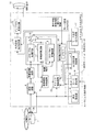
続いて本発明に係る再生装置の生産行為の形態について説明する。本発明に係る再生装置は、図2における内部構成図に基づき、工業的に生産することができる。
The 60 Hz
The above is a figure which shows the usage act of the reproducing | regenerating apparatus based on this invention.
Next, a description will be given of the form of production of the playback apparatus according to the present invention. The reproducing apparatus according to the present invention can be industrially produced based on the internal configuration diagram in FIG.
図2は、第1の実施形態に於ける再生装置のブロック図である。本図において、再生装置は、光ピックアップ2、モーター3、復調回路4、映像種別判別回路5、映像復調回路6、24Hz−60Hz変換回路7、走査変換回路8、60Hz−24Hz変換回路9、スイッチ10、出力設定GUI加算部11、ディジタル変換回路12、HDMI端子13、表示能力判定部14、再生設定部15、モード設定部16、モード設定GUI生成部17、出力周波数設定部18、スイッチ制御回路19から構成される。これらの構成要素のうち、HDMI端子13を除く復調回路4からスイッチ制御回路19までの部分は、1つのシステムL S Iとして集積される。
FIG. 2 is a block diagram of the playback apparatus according to the first embodiment. In this figure, the reproduction apparatus includes an
< 光ディスク1>
光ディスク1は、MPEG2方式( ITU−T勧告H. 262/ISO/IEC13818−2)で圧縮された映像信号が記録されたDVD−Videoである。
光ディスク1に記録された映像信号には、プログレッシブ映像信号、インタレース映像信号、及びプルダウン映像信号の3種類の映像信号が存在する。図3は、光ディスク1に記録される3種類の映像信号を示す図である。
<
The
In the video signal recorded on the
プログレッシブ映像信号は、フィルム撮像された映像信号が信号源となっている映像信号であり、図3の3−1段に示すような、2 4フレーム/秒のフレームn , n + 1 , n + 2 , n + 3からなる。
インタレース映像信号は、主にはビデオカメラで撮像された信号が信号源となっており、図3の3−2段に示すような30フレーム/秒、60フィールド/秒置きに出現するフィールドodd、even、odd、even、odd、even、odd、evenからなる。
The progressive video signal is a video signal whose source is a video signal that has been film-captured. As shown in FIG. 3 3-1, a
The interlaced video signal is mainly a signal picked up by a video camera, and a field odd appearing every 30 frames / second and 60 fields / second as shown in the 3-2 stage of FIG. , Even, odd, even, odd, even, odd, even.
プルダウン映像信号は、24フレーム/秒の映像を構成する信号源から各フレームを交互に2フィールドと3 フィールドとに変換するという3−2プルダウン変換で得られた信号である。プルダウン映像信号は、図3の3−3段に示すように30フレーム/秒、60フィールド/秒毎に出現するフィールドn odd、n even、n odd、n+1 even、n+1 odd、n+2 even、n+2 odd、n+2 evenからなる。 The pull-down video signal is a signal obtained by 3-2 pull-down conversion in which each frame is alternately converted into 2 fields and 3 fields from a signal source constituting a video of 24 frames / second. The pull-down video signal includes fields n odd, n even, n odd, n + 1 even, n + 1 odd, n + 2 even, n + 2 odd, which appear every 30 frames / second and 60 fields / second, as shown in FIG. , N + 2 even.
またディスク1には、圧縮された映像信号が順次走査されているか飛び越し走査されているかを示すフラグが、映像信号と共に記録されている。このようなフラグは、映像信号のフレーム又はフィールド単位に重畳されており、映像信号がこれらの何れの種類であるかを示す。従って、各フレーム又はフィールドに重畳されたフラグを参照することにより、1つのAVファイルの再生中に映像信号の種類が別のものに変化したとしても、その種類がどのようなものであるかを再生装置は知得することができる。
Further, a flag indicating whether the compressed video signal is sequentially scanned or interlaced is recorded on the
実際の映画では、本編の他に、カットシーン、インタビュー映像、メイキング映像といったものが記録されているが、これらは、それぞれプログレッシブ映像信号、インタレース映像信号、プルダウン映像信号というように、種類がバラバラになっていることが殆どである。また、編集の都合上、映画の本編を構成する1つのAVファイルにおいて、プログレッシブ映像信号、インタレース映像信号、プルダウン映像信号の映像が混合して存在することがある。このようなプログレッシブ映像信号、インタレース映像信号、プルダウン映像信号がそれぞれ混在した本編映像である1つのAVファイルの再生する場合、図4に示すように、AVファイルの読み出しにより得られる信号のフレーム周波数が24Hzである期間と、60Hzである期間とが生じる。以上がディスク1についての説明である。
In actual movies, in addition to the main part, cut scenes, interview videos, making videos, etc. are recorded, but these are divided into various types such as progressive video signals, interlaced video signals, and pull-down video signals. It is almost that. Also, for the convenience of editing, there may be a mixture of progressive video signals, interlace video signals, and pull-down video signals in one AV file that constitutes the main part of a movie. When reproducing one AV file that is a main video in which such progressive video signals, interlace video signals, and pull-down video signals are mixed, as shown in FIG. 4, the frame frequency of the signal obtained by reading the AV file is shown. A period of 24 Hz and a period of 60 Hz occur. This completes the description of the
<ピックアップ2、モーター3、復調回路4>
ピックアップ2は、DVD用ピックアップ2a、及びBD用ピックアップ2bからなり、ディスク1に記録された信号を電気的信号に変換する。読み出し時に何れのピックアップにより読み出しが可能であったかは、再生設定部15へ通知される。
モーター3は、ディスク1を再生に適した速度で回転させる。
<
The
The
復調回路4は、ピックアップ2の変換により電気信号を復調して、ビット列を得る。このビット列に対し誤り訂正などを行い、圧縮映像信号や再生に必要な付帯情報を出力する。
<映像種別判別回路5>
映像種別判別回路5は、復調回路4の出力と、映像復調回路6の出力とから、各フレーム若しくはフィールド毎に重畳された上述したフラグの値を参照して、ディスク1から再生された映像信号が、プログレッシブ映像信号であるか、インタレース映像信号であるか、プルダウン映像信号であるかを判別し、結果を走査変換回路8、60Hz−24Hz変換回路9、及びスイッチ制御回路19へ通知する。
The
<Video
The video
具体的には、映像種別判別回路5は、復調回路4の出力に重畳されている映像信号が順次走査されているか飛び越し走査されているかを示すフラグを読み込み、フラグが順次走査を示している場合には映像信号がプログレッシブ映像信号であると判別する。一方、フラグが飛び越し走査を示している場合には、映像復調回路6で映像信号に復調された信号の周期性により、映像信号がインタレース映像信号かプルダウン映像信号かを判別する。以下、信号の周期性に基づく、インタレース映像信号かプルダウン映像信号かの判別の詳細について説明する。
Specifically, the video
<映像種別判別回路5の詳細 インタレース映像信号、プルダウン映像信号の判別>
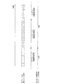
図5の5−1段は、プルダウン映像信号を示す。3−2プルダウン方式の特徴は、5フィールドに1回重複フィールドが存在する点である。この重複フィールドとは、2フィールド前と同じ内容をもつフィールドである。
映像種別判別回路5は、入力された映像信号を2フィールド分遅延させた遅延信号を生成する。図5の5−2段は、プルダウン映像信号を2フィールド分遅延させた遅延信号を示す。
<Details of Video Type
The 5-1 stage of FIG. 5 shows a pull-down video signal. A feature of the 3-2 pull-down method is that a duplicate field exists once in 5 fields. This duplicate field is a field having the same contents as two fields before.
The video
遅延信号を生成した映像種別判別回路5は、入力された映像信号と、遅延信号との対比により、5フィールドに1度一致するフィールド、即ち重複フィールドの有無を判定する。重複フィールドが発見された場合、入力された映像信号はプルダウン映像信号であり、この時、映像種別判別回路5は、5−3段に示すような一致したフィールドを示す信号を生成する。このように入力された映像信号と遅延信号との一致が5フィールドに1度発生するか否かに基づいて、映像種別判別回路5はインタレース映像信号とプルダウン映像信号を区別する。こうして得られた入力映像信号がプルダウン映像信号であるか否かの判定結果を、映像種別判別回路5 は、映像種別として走査変換回路8と60Hz-24Hz変換回路9とに通知する。
The video
< 映像復調回路6>
映像復調回路6は、復調回路4から出力される圧縮映像信号を復調してディジタル映像信号を得る。映像復調回路6で復調されたディジタル映像信号はスイッチ10のa接点と、24Hz-60Hz変換回路7と走査変換回路8とに入力される。
<24Hz-60Hz変換回路7>
24Hz-60Hz変換回路7は、24フレーム/秒で記録されたプログレッシブ映像信号を60Hzプログレッシブ映像信号に変換し、スイッチ10のb接点に出力する。図3の3−4段、3−5段は、24Hz-60Hz変換回路7の処理手順を示す。24Hz- 60Hz変換回路7は、図3の3−4段に示すようなプログレッシブ映像信号の各フレームのうちフレームn、n+2を、3つのフィールドに変換する。フレームn+1、n+3 を、2つのフィールドに変換する。これによって、3−5段に示すような60Hzプログレッシブ映像信号が得られる。
<
The
<24 Hz-60
The 24 Hz-60
< 走査変換回路8>
走査変換回路8は、映像復調回路6から出力された映像信号のうち飛び越し走査されている映像信号を、順次走査された60Hzプログレッシブ映像信号に変換し、スイッチ10のc接点と60Hz−24Hz変換回路9に出力する。ここで映像復調回路6から入力された飛び越し走査されている映像信号が、プルダウン映像信号である場合とプルダウン映像信号でない場合とで異なるアルゴリズムによる走査変換が実施される。図5を参照しながら、プルダウン映像信号を60Hzプログレッシブ映像に変換するアルゴリズムについて説明する。
<
The
入力信号がプルダウン映像信号である場合の走査変換回路8の出力を5−4段に示す。走査変換回路8は、重複フィールド位置から、3−2プルダウン変換が施される前の24フレーム/秒の信号源でのフレームの切れ目を検出し、それに伴って、変換前信号源でのフレーム毎にフィールドを結合させる。
例えば図5の5−3に示すように、フィールド重複信号が出力された場合、このフィールド重複信号の出力タイミングが変換前信号源でのフレームn、フレームn+2の切れ目であるとして、各フィールド重複信号が出力された後から次のフィールド重複信号が出力されるまでの5つのフィールドを、変換前信号源での2つのフレームを構成するものとして分類する。これにより5−1段に示すプルダウン映像信号から5−4段に示すような、フレームn、n、n、n+1、n+1、n+2、n+2、n+2、n+3、n+3というプログレッシブ映像信号の変換出力を得る。
The output of the
For example, as shown in 5-3 of FIG. 5, when a field duplication signal is output, it is assumed that the output timing of the field duplication signal is a break between the frame n and the frame n + 2 in the signal source before conversion. Are classified as constituting two frames in the signal source before conversion. As a result, a progressive video signal conversion output of frames n, n, n, n + 1, n + 1, n + 2, n + 2, n + 2, n + 3, and n + 3 as shown in stage 5-4 is obtained from the pull-down video signal shown in stage 5-1. .
尚、入力信号がプルダウン映像信号ではない場合における走査変換回路8の入出力を5−6、5−7段に示す。入力信号が、5−6段に示すようなインタレース映像信号であれば、走査変換回路8の変換により、5−7段に示すような60Hzプログレッシブ映像信号が得られる。
このように飛び越し走査されている映像信号には、フィルム素材を3−2プルダウン変換することで得られたものと、ビデオカメラ素材であるものとの2種類が存在する。走査変換回路8に入力されてくる飛び越し走査されている映像信号が、この2種類のうちどちらであるかは、映像種別判別回路5による種類判別の結果を待たないと判らない。そのため、先ず飛び越し走査されている映像信号を走査変換回路8に入力しておき、その後、映像種別判別回路5による種別判別の結果が下された後に、かかる映像信号に対して信号種別に応じたアルゴリズムを施すよう走査変換回路8において処理を切り換える。
Note that the inputs and outputs of the
There are two types of video signals that are interlaced and scanned in this way: those obtained by 3-2 pulldown conversion of film materials and those that are video camera materials. It cannot be determined which of the two types of interlaced video signals input to the
<60Hz−24Hz変換回路9>
60Hz−24Hz変換回路9は、走査変換回路8から出力された60フレーム/秒のプログレッシブ映像信号を24フレーム/秒の映像信号に変換し、スイッチ10のd接点に出力する。具体的にいうと、映像種別がプルダウン映像である場合には、図5の5−4に示すような走査変換回路8の出力を60Hz−24Hz変換回路9は、図5の5−5段に示すように、24フレーム/秒の映像信号に変換する。前述した様に、プルダウン映像信号とは、元24フレーム/秒の映像を構成する信号源の各フレームを交互に2フィールドと3フィールドとに変換したものであるから、この場合には、3−2プルダウン変換前の元の24フレーム/秒の映像信号に戻されたことになる。
<60 Hz-24
The 60 Hz-24
3−2プルダウンでは、変換前信号源の1のフレームに由来する連続した3フレームの出力と、変換前信号源の次の1のフレームに由来する連続した2フレーム出力とが繰り返されるので、映像の動きがぎこちなくなる。この動きのぎこちなさを解消するためには、上述した走査変換回路8、及び60Hz−24Hz変換回路9による変換が必要になる。
また、映像信号がインタレース信号である場合には図5の5−8段に示される様に、24フレーム/秒の信号に変換されるが、元の信号は60フレーム/秒であるので、図5の5−7段に示す元の映像からフレーム番号の、n,n+1、n+3、n+4、n+5、n+6、n+7、n+8、n+9のフレームが間引かれ、図5の5−8段に示す様にn,n+2、n+5、n+7のみが出力される事になる。このためインタレース映像信号が変換された24Hzプログレッシブ映像信号は、フレームが間引かれて不自然な動きの映像になる。
In the 3-2 pull-down, the output of 3 consecutive frames derived from one frame of the signal source before conversion and the continuous 2 frame output derived from the next 1 frame of the signal source before conversion are repeated. The movement becomes awkward. In order to eliminate this awkward movement, conversion by the above-described
If the video signal is an interlaced signal, it is converted to a signal of 24 frames / second as shown in FIG. 5-5, but the original signal is 60 frames / second. Frames n, n + 1, n + 3, n + 4, n + 5, n + 6, n + 7, n + 8, and n + 9 are thinned out from the original video shown in stage 5-7 in FIG. 5, and are shown in stage 5-8 in FIG. Similarly, only n, n + 2, n + 5, and n + 7 are output. For this reason, the 24 Hz progressive video signal obtained by converting the interlaced video signal becomes a video with an unnatural motion by thinning out the frames.
< スイッチ10>
スイッチ10は、a接点, b接点, c接点, d接点,e接点のどれかと接続することにより、映像復調回路6の出力、24Hz−60Hz変換回路7の出力、走査変換回路8の出力、60Hz−24Hz変換回路9の出力、モード設定GUI生成部17の出力を選択的に出力設定GUI加算部11に出力する。
<
The
<出力設定GUI加算部11>
出力設定GUI加算部11は、GUI生成手段の一つであって、出力周波数設定部18からの指示によって、映像信号出力をビデオレート及びフィルムレートの何れで行うかの選択をユーザに求める為のOSD(On Screen Display)グラフィクスを生成し、スイッチ10から入力される映像信号に生成したOSDグラフィックスを付加して、ディジタル変換回路12に出力する。
<Output
The output setting
<ディジタル変換回路12>
ディジタル変換回路12は、出力設定GUI加算部11から入力された24フレーム/秒プログレッシブ映像信号、60フレーム/秒プログレッシブ映像信号の何れかの映像信号に対して、HDMI形式のディジタル映像信号変調を行い、端子13を介して変調結果をモニタ400又は500に出力する。これにより映像信号が出画される。
<
The
< 端子13>
端子13は、HDMI規格( HDMI:High Definition Multimedia Interface)に準拠した端子であり、その中にはディジタル変調された映像信号伝送路と共に、VESA/D−DDC及びEIA/CEA861−B両規格で規定される相互通信用のシリアル伝送路が含まれている。端子13には、モニタ400、若しくは500が接続される。モニタ内部にはROMがあり、その中に、モニタの表示可能映像規格に関する情報(EDID)が格納されているので、上述したシリアル伝送路を介して、このROMに格納された表示可能映像規格に関する情報を読み出すことができる。
<
The terminal 13 is a terminal compliant with the HDMI standard (HDMI: High Definition Multimedia Interface), and is defined by both the VESA / D-DDC and EIA / CEA861-B standards together with a digitally modulated video signal transmission line. A serial transmission path for mutual communication is included. A
<表示能力判定部14>
表示能力判定部14は、“モニタの表示可能映像規格に関する情報(EDID)”をモニタ内部に存在するROMから、上述したシリアル伝送路を介して取り出して、この表示可能映像規格情報に基づき接続相手となるモニタが、ハイブリッドモニタ400であるか、60Hz専用モニタ500であるかを判定する。そしてその判定結果をスイッチ制御回路19とモード設定部16に通知する。
<Display
The display
<再生設定部15>
再生設定部15は、ユーザにより入力された指示に応じて装置の動作モード設定、及びディスク1の再生に関わる各ブロックの制御を指示する。
ユーザから装置の動作モード設定が指示された場合には、モード設定部16の動作を能動状態にし、後述する手続きによって、ユーザに選択に応じ動作モードをフィルムレート許可モード、及びフィルムレート不許可モードの何れかにを設定させる。
<
The
When an operation mode setting of the apparatus is instructed by the user, the operation of the
ユーザからディスク再生が指示された場合には、再生設定部15はピックアップ2、モーター3を制御して光ディスク1から信号読み出しを開始させる。この時、ピックアップ2からDVD用ピックアップ2aを用いて信号が読み出されたことが通知されると、出力周波数設定部18を能動状態にし、後述する手続きによって、ユーザ操作に応じて映像信号出力周波数を24フレーム/秒(フィルムモード)及び60フレーム/秒(ビデオモード)の何れか一方から他方へ変更できる様にする。
When a disc playback instruction is given by the user, the
<モード設定部16・モード設定GUI生成部17>
モード設定GUI生成部17は、GUI生成手段の一つであって、OSD(On Screen Display)グラフィクスやBML(Broadcast Markup Language)を用いて記述されたGUIを生成してハイブリッドモニタ400に出力し、ハイブリッドモニタ400に表示させる。
<
The mode setting
モード設定部16は、再生設定部15による制御によって動作状態が能動状態になると、動作モード設定を受け付けるためのGUIをモード設定GUI生成部17に生成させ、ハイブリッドモニタ400に出力させる。図6は、モード設定GUI生成部17により生成されるGUIを示す図である。本図におけるボタンは、それぞれフィルムレート許可モード、フィルムレート不許可モードを受け付けるものであり、ノーマル状態、フォーカス状態、アクティブ状態といった状態をもつ。
When the operation state becomes active under the control of the
“フィルムレート不許可モード”とは、再生途中のフレーム周波数を常に60フレーム/秒に固定されているモードである。“フィルムレート許可モード”とは、再生途中のフレーム周波数を、60フレーム/秒と24フレーム/秒とのどちらか一方から他方へユーザが変更できるモードである。
図6においてユーザは、リモコンにおける左右キーを押下することにより、フォーカス状態になるべきボタンを切り換えることができ、またモード設定部16は、Enterキーの押下に応じて、現在フォーカス状態にあるボタンに対応するモードを、再生装置のカレントモードとする。このGUIの最大の特徴は、再生装置をフィルムレート許可モードに設定する際のデメリットをユーザに提示し、理解を高める点である。図中の警告「フィルムレート許可モードでフィルムモードの場合には、映像の種類によっては、映像がフレームが間引かれた不自然な動きになる場合があります。その様な場合にはビデオモードを選択してください。」は、フィルムレート許可モードになる場合のデメリットを表している。フィルムレート許可モードに設定する際のデメリットを警告表示によってユーザに提示し理解させた上で、デフォルトの状態としてフレームレート不許可モードをフォーカス状態にしておく。これにより、ユーザは、インタレース映像信号が混合している場合に、フィルムレート許可モードでは画像が不自然な動きの映像信号になるなどのデメリットを理解した上で、再生装置をフィルムレート許可モードに設定するので、たとえフィルムレート許可モードでのインタレース映像信号の再生において、フレームが間引かれた不自然な動きが発生したとしても、商品苦情に発展することはない。
<出力周波数設定部18>
出力周波数設定部18は、変更受付手段として機能する機能ブロックであり、再生設定部15による制御によって能動状態になる。能動状態になると出力周波数設定部18は、動作モードがフィルムレート許可モードに設定されている時に、ユーザからの指示を受けて、再生出力するフレーム周波数を60フレーム/秒(ビデオモード)と24フレーム/秒(フィルムモード)との何れか一方から他方へ変更する。
The “film rate non-permission mode” is a mode in which the frame frequency during playback is always fixed at 60 frames / second. The “film rate permission mode” is a mode in which the user can change the frame frequency during playback from one of 60 frames / second and 24 frames / second to the other.
In FIG. 6, the user can switch the button to be focused by pressing the left / right key on the remote controller, and the
<Output
The output
具体的には、リモコン300は「出力変更」ボタンを有し、ユーザが「出力変更」ボタンの押下により出力設定用のGUI表示を要求すると、出力周波数設定部18は出力周波数変更処理を開始する。出力周波数変更処理では、先ず出力周波数設定部18は、再生中の映像情報に、出力周波数の設定機能をスーパーインポーズ表示するよう、出力設定GUI加算部11に指示する。このGUIにおいて24フレーム/秒(フィルムモード)、及び60フレーム/秒(ビデオモード)の何れかが選択された場合に、出力周波数設定部18は、選択された出力映像信号周波数をスイッチ制御回路19へ通知する。
Specifically, the
図7は出力設定GUI加算部11により生成されるGUIを示す図である。本図における「フィルム」、及び「ビデオ」の表示ボタンは、変更する出力レートを示すボタンであり、それぞれ24フレーム/秒(フィルムモード)、60フレーム/秒(ビデオモード)の映像信号周波数に対応し、ノーマル状態、フォーカス状態、アクティブ状態といった状態をもつ。出力設定用GUIの初期表示時には、現在の出力周波数に対応するボタンがフォーカス状態で描画される。
FIG. 7 is a diagram showing a GUI generated by the output setting
図7においてユーザは、リモコンにおける左右キーを押下することにより、フォーカス状態になるべきボタンを切り換えることができ、また出力周波数設定部18は、Enterキーの押下に応じて、現在フォーカス状態にあるボタンに対応する周波数を、再生装置が出力する映像信号周波数に設定する。
先述した様に、フィルムレート許可モードで再生中に、インタレース信号を24フレーム/秒のフィルムレートで出力することにより、映像の不自然な動きが発生する。しかし、ユーザは、ディスク1の再生中でも容易に上述した操作により出力する映像信号周波数を60フレーム/秒に変更し不都合を回避できるので、再生中の映像に不自然な動きが発生したとしても、商品苦情に発展することはない。
In FIG. 7, the user can switch the button to be in the focus state by pressing the left and right keys on the remote controller, and the output
As described above, when the interlace signal is output at a film rate of 24 frames / second during reproduction in the film rate permission mode, an unnatural motion of the video occurs. However, since the user can easily change the video signal frequency output by the above-described operation to 60 frames / second and avoid inconvenience even during playback of the
<スイッチ制御回路19>
スイッチ制御回路19は、光ディスク1に記録されているビデオストリームの種類と、再生装置の接続相手となるモニタの種類と、再生設定部15からの情報と、出力周波数設定部18からの通知との組み合わせに応じて、スイッチ10に対する制御を行う。以下、スイッチ制御回路19の詳細について説明する。
<スイッチ制御回路19の詳細その1>
(接続相手がハイブリッドモニタ400であり、24フレーム/秒(フィルムレート)出力である場合)
図8は、再生装置の接続相手がハイブリッドモニタ400であり、再生装置の状態設定がフィルムモードである場合の、走査変換回路8、60Hz−24Hz変換回路9の入出力と、スイッチ制御回路19によるスイッチ制御とを対応づけて示す図である。
<
The
<Details of
(When the connection partner is the
In FIG. 8, the input / output of the
本図における8−1段は、a接点にスルー出力されるプログレッシブ映像信号を示す。8−2段、はインタレース映像信号入力時における走査変換回路8の出力を示し、8−3段は、インタレース映像信号入力時における60Hz−24Hz変換回路9の出力を示す。8−4段、8−5段は、入力信号がプルダウン映像信号である場合の60Hz−24Hz変換回路9の入出力を示す。60Hz−24Hz変換回路9では図8の8−3段に示すように、プルダウン映像信号の元の映像の各フレームを60フレーム/秒に変換する。
The 8-1 stage in this figure shows the progressive video signal through-outputted to the a contact. Stage 8-2 indicates the output of the
そして8−6段は、映像復調回路6、走査変換回路8、60Hz−24Hz変換回路9の入出力が、8−1〜8−5である場合のスイッチ制御回路19によるスイッチ制御を示す。
映像信号がプログレッシブ映像信号であると判断している時、スイッチ制御回路19は、スイッチ10をa接点に設定し、映像復調回路6の出力を出力設定GUI加算部11にスルー出力する。
The stage 8-6 shows the switch control by the
When it is determined that the video signal is a progressive video signal, the
映像信号が図8の8−4段に示すようなプルダウン映像信号である場合、スイッチ10をd接点に設定し、図8の8−5段に示すように、60Hz−24Hz変換回路9の出力が出力設定GUI加算部11に出力され24フレーム/秒の映像信号が出力される。
映像信号がインタレース映像信号の場合も、スイッチ10をd接点に設定することにより、60Hz−24Hz変換回路9の出力が出力設定GUI加算部11に出力され24フレーム/秒の映像信号が出力される。
When the video signal is a pull-down video signal as shown in the 8-4 stage in FIG. 8, the
Even when the video signal is an interlaced video signal, by setting the
即ち、再生装置の接続相手がハイブリッドモニタ400であり、再生装置の出力周波数設定が24フレーム/秒(フィルムモード)である場合、出力設定GUI加算部11には、常に24フレーム/秒の映像信号が送り込まれることになる。
< スイッチ制御回路19の詳細その2>
(60フレーム/秒(ビデオモード)での出力)
図9は、再生装置の接続相手がハイブリッドモニタ400であり、再生装置の出力周波数設定がビデオモードである場合、もしくは60Hz専用モニタ500である場合の、24Hz−60Hz変換回路7、走査変換回路8の入出力と、スイッチ制御回路19によるスイッチ制御と対応づけて示す図である。
That is, when the playback device is connected to the
<Details of
(Output at 60 frames / second (video mode))
In FIG. 9, when the playback apparatus is connected to the
本図における9−1段、9−2段は、入力信号がプログレッシブ映像信号である場合の、24Hz−60Hz変換回路7の入出力を示す。この際、24Hz−60Hz変換回路7では図9の9−1に示すようなプログレッシブ映像信号の元の24フレーム/秒の映像の各フレームを交互に2フレームと3フレームに変換する。これにより9−2段に示すように、60フレーム/秒プログレッシブ映像信号が得られる。9−3段、9−4段は、入力信号がインタレース映像信号である場合の走査変換回路8の入出力を示す。図9の9−3段におけるインタレース映像信号は、9−4段に示すような60フレーム/秒プログレッシブ映像信号に変換される。
9-1 stage and 9-2 stage in the figure indicate input / output of the 24 Hz-60
図9の9−5段、9−6段は、入力信号がプルダウン映像信号である場合の走査変換回路8の入出力を示す。9−5段に示すようなプルダウン映像信号のインタレース映像信号は、9−6段に示すような60Hzプログレッシブ映像信号に変換される。9−7段は、24Hz−60Hz変換回路7、走査変換回路8の入出力が、9−1〜9−6に示す場合のスイッチ制御回路19によるスイッチ制御を示す。
9-5 and 9-6 indicate input / output of the
映像信号が24Hzのプログレッシブ映像信号であると判断している場合、スイッチ10をb接点に設定し、24Hz−60Hz変換回路7の出力を出力設定GUI加算部11に出力する。
映像信号がインタレース映像信号か、もしくはプルダウン映像信号である場合、スイッチをc接点に設定し、走査変換回路8の出力を出力設定GUI加算部11に出力する。従って、出力設定GUI加算部11には、常に60フレーム/秒の映像信号が送り込まれることになる。
When it is determined that the video signal is a 24 Hz progressive video signal, the
When the video signal is an interlace video signal or a pull-down video signal, the switch is set to the c contact, and the output of the
即ち、再生装置の接続相手がハイブリッドモニタ400であり、再生装置の出力周波数設定が60フレーム/秒(ビデオ)モードである場合、もしくは、再生装置の接続相手が60Hz専用モニタ500である場合には上述した切り替えによって、出力設定GUI加算部11には、常に60フレーム/秒の映像信号が送り込まれることになる。
< スイッチ制御回路19の詳細その3>
ユーザ操作に応じて再生設定部15が装置の動作モード設定を指示している時には、スイッチ制御回路19はスイッチ10の接続をe接点に設定する。これにより、装置の動作モード設定中に、図6に示す動作モード設定を受け付けるためのGUIが表示され、ユーザは前述した操作により、フィルムレート許可モード、フィルムレート不許可モードの何れかを選択する事ができる。
That is, when the connection partner of the playback apparatus is the
<Details of
When the
従って、ユーザは、画質を優先させて再生したい時には、先ずフィルムレート許可モードを選択し、再生中に、図7に示すGUIをディスク内容に応じて操作することで、出力周波数を24フレーム/秒(フィルムモード)、60フレーム/秒(ビデオモード)の何れかに適時変更させれば良い。この時、出力周波数の変更に伴いHDMI接続の再同期が発生するが、このような再同期の発生は出力周波数の変更操作を明示的に行ったユーザにとって予期れているものであるため、商品苦情に発展することはない。
<ソフトウェア>
以降、表示能力判定部14、再生設定部15、モード設定部16、出力周波数設定部18、スイッチ制御回路19のソフトウェアによる実装について説明する。表示能力判定部14、再生設定部15、モード設定部16、出力周波数設定部18、スイッチ制御回路19は、図10、及び図11の処理手順をなすプログラムを作成してCPUに実行させることにより、再生装置内に実装することができる。
Therefore, when the user wants to reproduce with priority on the image quality, first, the film rate permission mode is selected, and the GUI shown in FIG. 7 is operated according to the disc contents during reproduction, so that the output frequency is 24 frames / second. (Film mode) or 60 frames / second (Video mode) may be changed as appropriate. At this time, resynchronization of the HDMI connection occurs with the change of the output frequency, but such resynchronization is expected for the user who has explicitly performed the operation of changing the output frequency. It does not develop into a complaint.
<Software>
Hereinafter, software implementation of the display
図10及び図11は、表示能力判定部14、再生設定部15、モード設定部16、出力周波数設定部18、スイッチ制御回路19による再生装置の全体制御の手順を示すフローチャートである。
図10、図11において、本再生装置が起動されれば、ステップS1にて初期設定処理として、モード設定部16により動作モードがフィルムレート不許可モードに、出力周波数設定部18により出力周波数が60フレーム/秒にそれぞれ設定され、その後、ステップS2のループ処理に移行する。ステップS2は、モニタとの接続がなされたか否かの判定であり、このループ処理は、モニタとの接続がなされれば、ステップS3に移行する。ステップS3は、表示能力判定部14が、HDMIの相互通信用シリアル伝送路を通じて、表示可能映像規格に関する情報をモニタから取り出す処理である。ステップS4は、再生設定部15が実行する処理であり、表示能力判定部14により取り出された表示可能映像規格に関する情報に基づいて、動作モードを設定するステップS5の処理を実行するか否かを切り換える判定ステップである。接続相手となるモニタが、60Hz走査のみを可能としているなら、S6に移行する。接続相手となるモニタが、24Hz走査、60Hz走査の両方を可能としているなら、再生設定部15は、モード設定部16にステップS5の処理を実行させる。
FIG. 10 and FIG. 11 are flowcharts showing the overall control procedure of the playback apparatus by the display
10 and 11, when the playback apparatus is activated, as an initial setting process in step S1, the
ステップS5は、両方の走査が可能である場合、フィルムレート許可モード、フィルムレート不許可モードの何れかの設定を受け付けるGUIを表示し、動作モードの設定を受付ける動作モード設定処理である。ここではモード設定部16がモード設定GUI生成部17に図6に示すGUIを生成させ、リモコンによるユーザの動作モード選択を受付ける。
Step S5 is an operation mode setting process for displaying a GUI for accepting the setting of either the film rate permission mode or the film rate disapproval mode and accepting the setting of the operation mode when both scans are possible. Here, the
ステップS6は、ユーザの再生指示を待ち受ける処理である。このステップでは、再生設定部15は、ユーザがリモコンを操作して再生を指示するのを待っており、再生が指示されるとピックアップ2及びモーター3を制御して光ディスク1から信号読み出しを開始させる。この時、ピックアップ2の制御回路から再生設定部15に、DVD用ピックアップ2a、及びBD用ピックアップ2bの何れを用いて信号が読み出されたかが通知される。
Step S6 is processing for waiting for a user's reproduction instruction. In this step, the
ここで通知された使用ピックアップが、BD用ピックアップ2bであれば(ステップS7:No)、ステップS8に移行し、BD−ROMに最適化した再生処理が再生終了まで実行される。BD−ROMに最適化した再生処理としては、特開2006−222938号に記載の技術の適用が考えられる。一方、通知された使用ピックアップが、DVD用ピックアップ2aであれば(ステップS7:Yes)、ステップ9に移行し、DVD−Videoに最適化した再生処理が実行される。以下、本発明に特徴的な処理を実装したDVD−Videoの再生処理を主眼に説明する。
If the used pickup notified here is the
ステップS9は、設定されている動作モードがフィルムレート許可モード、及びフィルムレート不許可モードの何れであるかを再生設定部15において判定する処理であり、動作モードがフィルムレート許可モードであれば処理をステップS10に移行し、動作モードがフィルムレート不許可モードであれば図11のCを経由してステップS21〜ステップS28のビデオレートでの再生処理を実行する。
Step S9 is processing for determining in the
ステップS10では、ユーザが出力周波数の変更を要求しているか否かを出力周波数設定部18において確認するステップである。これは、ユーザが再生中にリモコンの「出力変更」を押下して、再生周波数の変更をしようとしているかを検知する処理であり、出力周波数変更の要求が検出された場合には、出力周波数を24フレーム/秒(フィルムモード)、60フレーム/秒(ビデオモード)の何れにするかをユーザに設定させるステップS11が実行された後に、ステップS12以降の再生処理が継続される。ステップS10において、ユーザからの出力周波数変更要求が検出されない場合にはステップS11を実行することなく、ステップS12以降の再生処理が継続される。
In step S10, the output
ステップS11では、出力周波数設定部18が出力設定GUI加算部11に図7に示すGUIの加算を指示し、リモコン操作によるユーザからの指示を受付け、ユーザ指示に応じて出力周波数を変更する。
ステップS12〜ステップS28は、いわば本実施形態の主眼となる処理を構成するものであり、ステップS12にて判定される出力周波数の設定に応じて、ステップS13〜ステップS20のフィルムレートでの再生と、ステップS21〜ステップS28のビデオレートでの再生とに分岐する。フィルムレートでの再生は、ステップS13〜ステップS14の実行結果に応じて、スイッチ制御回路19がスイッチ10をa接点に切り換える処理(ステップS18)及びスイッチ10をd接点に切り換える処理(ステップS19、S20)を実行するものであり、ビデオレートでの再生は、ステップS21〜ステップS22の実行結果に応じて、スイッチ制御回路19がスイッチ10をb接点に切り換える処理(ステップS26)及びスイッチ10をc接点に切り換える処理(ステップS27、S28)を実行するものである。
In step S11, the output
Steps S12 to S28 constitute the processing that is the main point of the present embodiment, and playback at the film rate in steps S13 to S20 according to the setting of the output frequency determined in step S12. Branches to playback at the video rate in steps S21 to S28. In reproduction at the film rate, the
先ず、ステップS12の処理について説明する。ステップS12は、出力周波数の設定が60フレーム/秒(ビデオモード)に設定されているか、24フレーム/秒(フィルムモード)に設定されているかを、出力周波数設定部18からの通知に応じてスイッチ制御回路19が判定するステップであり、出力周波数設定が24フレーム/秒(フィルムモード)である場合にはステップS13に移行し、出力周波数設定が60フレーム/秒(ビデオモード)である場合は、ステップS21に移行する。
<フィルムレートでの再生>
ステップS13〜ステップS20のフィルムレートでの再生において、スイッチ制御回路19が、ステップS18〜ステップS20の何れの接点切替処理を実行するかは、ステップS13、ステップS14の判定結果に従う。
First, the process of step S12 will be described. In step S12, whether the output frequency is set to 60 frames / second (video mode) or 24 frames / second (film mode) is switched according to the notification from the output
<Reproduction at film rate>
In the reproduction at the film rate in steps S13 to S20, which contact switching processing in steps S18 to S20 is executed by the
ステップS13は、映像信号に伴うフラグが順次走査を示すかどうかを映像種別判別回路5において判定する判定ステップであり、もし順次走査を示すフラグであれば、ステップS15において入力信号がプログレッシブ映像信号であると認定し、認定結果をスイッチ制御回路19へ通知する。入力信号がプログレッシブ映像信号であると通知されたスイッチ制御回路19では、ステップS18の接点切替処理がが実行される。
Step S13 is a determination step in which the video
一方、映像信号に伴うフラグが、飛び越し走査を示す場合、映像種別判別回路5では更にステップS14の判定が実行される。ステップS14は、重複フィールドが存在するかどうかの判定であり、もし重複フィールドが存在すれば、ステップS17において入力信号がプルダウン映像信号であると認定し、認定結果をスイッチ制御回路19へ通知する。入力信号がプルダウン映像信号であると通知されたスイッチ制御回路19では、ステップS20の接点切替処理が実行される。
On the other hand, when the flag accompanying the video signal indicates interlaced scanning, the video
もしステップS14の判定において重複フィールドが存在しなければ、ステップS16において、入力信号がインタレース映像信号であると認定して、認定結果をスイッチ制御回路19へ通知する。入力信号がインタレース映像信号であると通知されたスイッチ制御回路19では、ステップS19の接点切替処理が実行される。
<ビデオレートでの再生>
ステップS21〜ステップS28のビデオレートでの再生において、スイッチ制御回路19が、ステップS26〜ステップS28の何れの接点切替処理を実行するかは、ステップS21、ステップS22の判定結果に従う。
If there is no duplicate field in the determination in step S14, the input signal is recognized as an interlaced video signal in step S16, and the result of the recognition is notified to the
<Playback at video rate>
In the reproduction at the video rate in steps S21 to S28, which contact switching processing in steps S26 to S28 is executed by the
ステップS21は、映像信号に伴うフラグが順次走査を示すかどうかを映像種別判別回路5において判定する判定ステップであり、もし順次走査を示すフラグであれば、ステップS23において入力信号がプログレッシブ映像信号であると認定し、認定結果をスイッチ制御回路19へ通知する。入力信号がプログレッシブ映像信号であると通知されたスイッチ制御回路19では、ステップS26の接点切替処理がが実行される。
Step S21 is a determination step in which the video
一方、映像信号に伴うフラグが、飛び越し走査を示す場合、映像種別判別回路5では更にステップS22の判定が実行される。ステップS22は、重複フィールドが存在するかどうかの判定であり、もし重複フィールドが存在すれば、ステップS25において入力信号がプルダウン映像信号であると認定し、認定結果をスイッチ制御回路19へ通知する。入力信号がプルダウン映像信号であると通知されたスイッチ制御回路19では、ステップS28の接点切替処理が実行される。
On the other hand, when the flag accompanying the video signal indicates interlaced scanning, the video
もしステップS22の判定において重複フィールドが存在しなければ、ステップS24において、入力信号がインタレース映像信号であると認定して、認定結果をスイッチ制御回路19へ通知する。入力信号がインタレース映像信号であると通知されたスイッチ制御回路19では、ステップS27の接点切替処理が実行される。
上述のステップS18〜ステップS20、及びステップS26〜ステップS28の接点切替処理の後、映像信号再生状態の入力が続いている限り、図10のBを経由してステップS7へ移行する処理を繰り返す。ステップS29において再生設定部15が、ユーザによる停止指示を受け付けた場合、若しくはAVファイル終端までの再生完了が検知された場合、再生を終了する。以上が、図10、図11に示した再生装置の全体制御の説明である。
If there is no overlapping field in the determination in step S22, it is recognized that the input signal is an interlaced video signal in step S24, and the result of the recognition is notified to the
After the contact switching process in steps S18 to S20 and steps S26 to S28, the process of moving to step S7 via B in FIG. 10 is repeated as long as the input of the video signal reproduction state continues. When the
以上のように本実施形態によれば、記録媒体から読み出された映像信号のフレーム周波数と、接続されているモニタの表示可能フレーム周波数とを検出し、それに応じて出力映像信号のフレーム周波数を変更でき、且つ、24フレーム/秒(フィルムモード)で出画するか、60フレーム/秒(ビデオモード)で出画するかをユーザが選択できる。そのため、万一インタレース素材を24フレーム/秒(フィルムモード)出力状態で再生して、フレームが間引かれて不自然な動きの映像になったとしても、ユーザは容易に60フレーム/秒(ビデオモード)の出力設定に戻す事ができる。 As described above, according to the present embodiment, the frame frequency of the video signal read from the recording medium and the displayable frame frequency of the connected monitor are detected, and the frame frequency of the output video signal is determined accordingly. The user can select whether to display at 24 frames / second (film mode) or 60 frames / second (video mode). Therefore, even if interlaced material is played back at 24 frames / second (film mode) and the frame is thinned out to produce an unnatural motion, the user can easily play 60 frames / second ( (Video mode) output settings can be restored.
更に、初期状態では60フレーム/秒(ビデオモード)に出力が設定されている為、ユーザが明示的にフィルムレート許可モードに設定しないと、再生中に24フレーム/秒(フィルムモード)の出力を選択できない構成になっており、かつ24フレーム/秒(フィルムモード)出力許可する際にはGUIにて画面上に注意事項が表示されるので、24フレーム/秒(フィルムモード)出力に関する知識の低いユーザが間違う事も少なくなるという利点がある。 Furthermore, since the output is set to 60 frames / second (video mode) in the initial state, if the user does not explicitly set the film rate permission mode, 24 frames / second (film mode) is output during playback. When it is configured so that it cannot be selected and 24 frames / second (film mode) output is permitted, a caution is displayed on the screen on the GUI, so knowledge about 24 frames / second (film mode) output is low. There is an advantage that the user is less likely to make a mistake.
また本実施形態に係る再生装置は、接続相手となる表示装置が60フレーム/秒、及び24フレーム/秒の両方の映像信号の表示能力を具備している場合のみ、24フレーム/秒での信号出力を許可するフィルムレート許可モードが選択できるようになるので、接続相手となる表示装置が60フレーム/秒の映像信号しか表示できないのに、24フレーム/秒の信号出力を実行するモードを、ユーザに選択させてしまうような不都合も避けることができる。かかる不都合を避けることができるので、24フレーム/秒の信号出力を存分に発揮して、高画質な映像でユーザを魅了することができる。 In addition, the playback device according to the present embodiment is a signal at 24 frames / second only when the display device to be connected has a display capability of both 60 frames / second and 24 frames / second. Since the film rate permission mode for permitting output can be selected, the user can set the mode for executing the signal output of 24 frames / second even though the display device as the connection partner can display only the video signal of 60 frames / second. The inconvenience of letting the user select can be avoided. Since such inconvenience can be avoided, the signal output of 24 frames / second can be fully exhibited, and the user can be attracted with high-quality video.
また、本実施形態では、動作モードをユーザから受け付けるグラフィクスユーザインターフェイスにおいて、60フレーム/秒の映像信号を24フレーム/秒で出力した場合、表示装置における表示が、フレームの間引かれた不自然な動きの映像になる可能性がある旨をユーザに警告している。これにより、信号混在時の映像が、フレームの間引かれた不自然な動きになる可能性をユーザに周知させた上で、24フレーム/秒での出力を許可するモードの選択を行わせるので、再生時に映像が、フレームの間引かれた不自然な動きになる事が生じたとしても、このような不自然な動きが商品苦情に発展することは稀有となる。 In this embodiment, when a video signal of 60 frames / second is output at 24 frames / second in a graphics user interface that accepts an operation mode from a user, the display on the display device is unnatural. The user is warned that there is a possibility of moving images. This makes it possible to select a mode that allows output at 24 frames / second, after notifying the user of the possibility of unnatural movements of frames that are thinned out when signals are mixed. Even if an image is unnaturally moved out of the frame during playback, it is rare that such unnaturally motion is developed into a product complaint.
(第2実施形態)
第2実施形態は、モニタがマルチスキャン対応モニタであることを想定した実施形態である。マルチスキャン対応モニタとは、再生装置から指示された表示時の走査周波数で、表示を行うモニタである。本実施形態では、このマルチスキャン対応モニタに、24フレーム/秒の整数倍である48Hzでの走査により、映像再生を行わせる。フィルム素材は、第1実施形態に示したような24フレーム/秒での表示に適しているが、24フレーム/秒では、フリッカが出現する可能性がある。このようなフリッカを避けるべく、映画館の映写機では、1枚のフレームに対し2回の投光を行っている。そのため、本実施形態において再生装置が48フレーム/秒での映像表示を行えば、その表示時の品質は、映画館で見る品位に準ずるものとなる。
(Second Embodiment)
The second embodiment is an embodiment assuming that the monitor is a multi-scan compatible monitor. The multi-scan compatible monitor is a monitor that performs display at the scanning frequency at the time of display instructed from the reproduction apparatus. In the present embodiment, the multi-scan compatible monitor is caused to reproduce video by scanning at 48 Hz, which is an integer multiple of 24 frames / second. The film material is suitable for display at 24 frames / second as shown in the first embodiment, but flicker may occur at 24 frames / second. In order to avoid such flicker, a movie projector in a movie theater emits light twice for one frame. For this reason, if the playback apparatus performs video display at 48 frames / second in the present embodiment, the quality at the time of display conforms to the quality seen in a movie theater.
以降、第2実施形態に係る再生装置の内部構成について説明する。図12は、第2実施形態に係る再生装置の内部構成を示す図である。本図に示すように、第2実施形態に係る再生装置は、表示周波数指示部20 、24Hz−48Hz変換回路21が新規に追加されており、60Hz−24Hz変換回路9が60Hz−48Hz変換回路22に置き換えられている。また、これらの構成要素が追加されたため、表示能力判定部14及びスイッチ制御回路19は、以下に示すような第2実施形態特有の処理を行う。フィルムモードでの出力として24フレーム/秒に変えて48フレーム/秒の映像信号を出力する。以下、これらの改良点と、新規な構成要素について説明する。
Hereinafter, the internal configuration of the playback apparatus according to the second embodiment will be described. FIG. 12 is a diagram illustrating an internal configuration of a playback apparatus according to the second embodiment. As shown in the figure, in the playback apparatus according to the second embodiment, a display
<第2実施形態における表示能力判定部14の改良>
表示能力判定部14は、“モニタの表示可能映像規格に関する情報”をモニタ内部に存在するROMから、上述したシリアル伝送路を介して取り出して、この表示可能映像規格情報に基づき接続相手となるモニタが、マルチスキャン対応モニタであるか否かを判定する。
<Improvement of Display
The display
<表示周波数指示部20>
表示周波数指示部20 は、接続相手となるモニタが、マルチスキャン対応モニタであると表示能力判定部14が判定した場合、HDMIを介して、出力周波数設定部18により設定された表示を行うべき走査周波数を、接続相手となる表示装置に通知する。ここでいう“ 表示を行うべき走査周波数”とは、上述の48フレーム/秒もしくは60フレーム/秒のことであり、出力周波数設定部18により出力周波数の設定が変更された場合、かかる走査周波数での表示を表示装置に命じる。
<Display
The display
<24Hz−48Hz変換回路21>
24Hz−48Hz変換回路21は、映像復調回路6から出力された24Hzプログレッシブ映像信号を、48フレーム/秒の映像信号に変換する。図13は、24Hz−48Hz変換回路21の入出力を現した図である。本図における13−1段は、24Hz−48Hz変換回路21への入力信号(プログレッシブ映像信号)を示し、13−2段は、24Hz−48Hz変換回路21からの出力信号を示す。本図を参照すると、12−1段のようなプログレッシブ映像信号を構成するフレームn、n+1、n+2からフレームn、n、n+1、n+1、n+2、n+2が生成されていることがわかる。
<24 Hz-48
The 24 Hz-48
<60Hz−48Hz変換回路22>
60Hz−48Hz変換回路22は、走査変換回路8から出力された60Hzプログレッシブ映像信号を、48フレーム/秒の映像信号に変換して出力する。図13の13−3段〜13−5段は、図5の5−3段〜5−5段と同様の表記で現した60Hz−48Hz変換回路22の入出力を示す。この出力も、プルダウン映像信号における3つのフィールド (n、n、n)から2つのフレーム(n、n)が出力され、プルダウン映像信号において後続する2つのフィールド(n+1、n+1)から2つのフレーム(n+1、n+1)が出力されることがわかる。
<60 Hz-48
The 60 Hz-48
<第2実施形態におけるスイッチ制御回路19の改良>
光ディスク1から読み出された映像信号がプログレッシブ映像信号又はプルダウン映像信号であれば、24Hz−48Hz変換回路21、60Hz−48Hz変換回路22から48フレーム/秒の映像信号が出力される。スイッチ制御回路19は、出力周波数としてフィルムモードに設定された状況において、48フレーム/秒の映像信号を接続先のモニタへ出力するために、図14に示すように、スイッチ10の切り換えを行うよう制御する。
<Improvement of
If the video signal read from the
図14は、再生装置の接続相手がマルチスキャン対応モニタであり、再生装置の出力周波数がフィルムモードである場合の24Hz−48Hz変換回路21、及び60Hz−48Hz変換回路22の入出力と、スイッチ制御回路19によるスイッチ制御と対応づけて示す図である。本図における14−1、14−2段は、24Hz−48Hz変換回路21における入出力を示す。14−3段、14−4段は、入力信号がインタレース映像信号入力時である場合の60Hz−48Hz変換回路22の入出力を示す。14−5段、14−6段は、入力信号がプルダウン映像信号である場合の60Hz−48Hz変換回路22の入出力を示す。
FIG. 14 shows the input / output of the 24 Hz-48
そして14−7段は、出力周波数がフィルムモードに設定されており、24Hz−48Hz変換回路21、60Hz−48Hz変換回路22の入出力が、14−1〜14−6である場合のスイッチ制御回路19によるスイッチ制御を示す。以下に、出力周波数がフィルムモードに設定されている場合のスイッチ制御回路19の動作を説明する。
光ディスク1から読み出された映像信号がプログレッシブ映像信号であると判断されている時、スイッチ制御回路19は、スイッチ10をa接点に設定し、24Hz−48Hz変換回路21の出力を出力設定GUI加算部11に出力する。
The 14-7 stage is a switch control circuit when the output frequency is set to the film mode and the input / output of the 24 Hz-48
When it is determined that the video signal read from the
光ディスク1から読み出された映像信号が図14の14−5段に示すようなプルダウン映像信号である場合、スイッチ10をd接点に設定し、図14の14−6段に示す60Hz−48Hz変換回路22の出力が出力設定GUI加算部11に出力され48フレーム/秒の映像信号がモニタへ出力される。
光ディスク1から読み出された映像信号がインタレース映像信号の場合も、スイッチ10をd接点に設定することにより、60Hz−48Hz変換回路22の出力が出力設定GUI加算部11に出力され48 フレーム/秒の映像信号がモニタへ出力される。
When the video signal read from the
Even when the video signal read from the
即ち、本実施の形態では、再生装置の接続相手がマルチスキャン対応モニタであり、再生装置の出力周波数設定がフィルムモードである場合においては常に48フレーム/秒の映像信号がGUI加算部11に出力される。
また本実施形態では、再生装置の接続相手がマルチスキャン対応モニタであり、再生装置の出力周波数設定が60フレーム/秒(ビデオモード)である場合、もしくは、再生装置の接続相手が60Hz専用モニタ500である場合には第1実施形態において説明した動作と同様の動作によって、GUI加算部11には、常に60フレーム/秒の映像信号が送り込まれる。
In other words, in the present embodiment, when the playback apparatus is connected to a multi-scan monitor and the output frequency setting of the playback apparatus is the film mode, a video signal of 48 frames / second is always output to the
In the present embodiment, the connection partner of the playback device is a multi-scan monitor, and when the output frequency setting of the playback device is 60 frames / second (video mode), or the connection partner of the playback device is a
以上のように本実施形態によれば、接続されている表示装置に、48フレーム/秒での表示を行わせて、映画館のような再生品位を、ユーザに堪能させることができる。また、万一インタレース素材を48フレーム/秒(フィルムモード)出力状態で再生して、フレームが間引かれて不自然な動きの映像になったとしても、ユーザは容易に60フレーム/秒(ビデオモード)の出力設定に戻す事ができる。 As described above, according to the present embodiment, the connected display device can perform display at 48 frames / second so that the user can enjoy the reproduction quality like a movie theater. Even if the interlaced material is played back at 48 frames / second (film mode) and the frame is thinned out to produce an unnatural motion, the user can easily play 60 frames / second ( (Video mode) output settings can be restored.
更に、初期状態では60フレーム/秒(ビデオモード)で出力が設定されている為、ユーザが明示的に48フレーム/秒(フィルムモード)の設定を許可しないと、再生中に48フレーム/秒(フィルムモード)の出力を選択できない構成になっており、かつ48フレーム/秒(フィルムモード)出力許可する際にはGUIにて画面上に注意事項が表示されるので、48フレーム/秒(フィルムモード)出力に関する知識の低いユーザが間違う事も少なくなるという利点がある。 Furthermore, since the output is set at 60 frames / second (video mode) in the initial state, if the user does not explicitly permit the setting of 48 frames / second (film mode), 48 frames / second ( When the output of 48 frames / second (film mode) is permitted, the GUI displays a notice on the screen when 48 frames / second (film mode) is selected. ) There is an advantage that users with low knowledge about output are less likely to make mistakes.
(第3実施形態)
第3実施形態は、第2実施形態同様、モニタがマルチスキャン対応モニタであることを想定した実施形態である。マルチスキャン対応モニタとは、再生装置から指示された表示時の走査周波数で、表示を行うモニタである。本実施形態では、このモニタに、24フレーム/秒の整数倍である72Hzでの走査により、映像再生を行わせる。
(Third embodiment)
As in the second embodiment, the third embodiment is an embodiment assuming that the monitor is a multi-scan compatible monitor. The multi-scan compatible monitor is a monitor that performs display at the scanning frequency at the time of display instructed from the reproduction apparatus. In the present embodiment, the monitor is caused to reproduce video by scanning at 72 Hz, which is an integer multiple of 24 frames / second.
以降、第3実施形態に係る再生装置の内部構成について説明する。図15は、第3実施形態に係る再生装置の内部構成を示す図である。本図は、図12に示した、第2実施形態に係る再生装置の内部構成をベースにしている。図12に示す再生装置に比較して、図15に示す第3実施形態に係る再生装置は、表示周波数指示部20、24Hz−48Hz変換回路21、60Hz−48Hz変換回路22、及び出力設定GUI加算部11が、それぞれ表示周波数指示部23、24Hz−72Hz変換回路24、60Hz−72Hz変換回路25、及び出力設定・ワーニングGUI加算部26に置き換えられている点と、ワーニング発生部27が加えられている点が異なる。また、これらの要素が置換・追加されたため、スイッチ制御回路19は、以下に示すような第3実施形態特有の処理を行う。このような構成により、フィルムモードにおいては48フレーム/秒に変えて72フレーム/秒の映像信号を出力する。以下、これらの改良点と、新規な構成要素について説明する。
Hereinafter, the internal configuration of the playback apparatus according to the third embodiment will be described. FIG. 15 is a diagram illustrating an internal configuration of a playback apparatus according to the third embodiment. This figure is based on the internal configuration of the playback apparatus according to the second embodiment shown in FIG. Compared with the playback device shown in FIG. 12, the playback device according to the third embodiment shown in FIG. 15 includes a display
<表示周波数指示部23>
表示周波数指示部23は、接続相手となるモニタが、マルチスキャン対応モニタであると表示能力判定部14が判定した場合、HDMIを介して、出力周波数設定部18により設定された表示を行うべき走査周波数を、接続相手となる表示装置に通知する。ここでいう“ 表示を行うべき走査周波数”とは、72フレーム/秒もしくは60フレーム/秒のことであり、出力周波数設定部18により出力周波数の設定が変更された場合、かかる走査周波数での表示を表示装置に命じた上で、フィルムモードにおいて、72フレーム/秒での信号出力を、24Hz−72Hz変換回路24、60Hz−72Hz変換回路25に行わせる。
<Display
The display
<24Hz−72Hz変換回路24>
24Hz−72Hz変換回路24は、映像復調回路6から出力されたプログレッシブ映像信号を、72フレーム/秒に変換する。
図16は、24Hz−72Hz変換回路24の入出力を現した図である。本図における16−1段は、24Hz−72Hz変換回路24への入力信号(プログレッシブ映像信号)を示し、16−2段は、24Hz−72Hz変換回路24からの出力信号を示す。本図を参照すると、16−1段のようなプログレッシブ映像信号を構成するフレームn、n+1、n+2からフレームn、n、n、n+1、n+1、n+1、n+2、n+2、n+2、が生成されていることがわかる。
<24 Hz-72
The 24 Hz-72
FIG. 16 is a diagram showing the input / output of the 24 Hz-72
<60Hz−72Hz変換回路25>
60Hz−72Hz変換回路25は、走査変換回路8から出力された映像信号が60Hzプログレッシブ映像信号である場合、これを72フレーム/秒に変換して出力する。
以上が24Hz−72Hz変換回路24、60Hz−72Hz変換回路25についての説明である。24Hz−48Hz変換回路21、60Hz−48Hz変換回路22 が、24Hz−72Hz変換回路24、60Hz−72Hz変換回路25 に置き換えられたため、スイッチ制御回路19は、以降のようなスイッチ切り換えを実行する。
<60 Hz-72
When the video signal output from the
This completes the description of the 24 Hz-72
< スイッチ制御回路19>
スイッチ制御回路19は第3実施形態において、出力周波数がフィルムモードに設定されている場合に、図16の16−3段に示すように、スイッチ10の切り換えを行うよう制御する。16−3段は、出力周波数がフィルムモードでの、第3実施形態に係るスイッチ制御回路19によるスイッチ制御を示す。
<
In the third embodiment, the
再生装置がフィルムモードに設定されており、入力となる映像信号がプログレッシブ映像信号であると判断されている時、スイッチ制御回路19は、スイッチ10をa接点に設定し、24Hz−72Hz変換回路24の出力を出力設定・ワーニングGUI加算部26に出力させる。これにより、モニタには72フレーム/秒の映像信号が出力されることになる。
When the playback apparatus is set to the film mode and it is determined that the video signal to be input is a progressive video signal, the
また、再生装置がフィルムモードに設定されており、入力となる映像信号がプルダウン映像信号、若しくはインタレース映像信号であると判断されている場合、スイッチ制御回路19は、スイッチ10をd接点に設定し、60Hz−72Hz変換回路25の出力を出力設定・ワーニングGUI加算部26に出力させる。
即ち、本実施の形態では、再生装置の接続相手がマルチスキャン対応モニタであり、再生装置の状態設定がフィルムモードである場合においては常に72フレーム/秒の映像信号が出力設定・ワーニングGUI加算部26に出力される。
When the playback device is set to the film mode and the input video signal is determined to be a pull-down video signal or an interlaced video signal, the
In other words, in this embodiment, when the playback device is connected to a multi-scan monitor and the playback device status is set to the film mode, a video signal of 72 frames / second is always output setting / warning GUI addition unit. 26.
また本実施形態では、再生装置の接続相手がマルチスキャン対応モニタであり、再生装置の出力周波数設定が60フレーム/秒(ビデオモード)である場合、もしくは、再生装置の接続相手が60Hz専用モニタ500である場合には第1実施形態において説明した動作と同様の動作によって、出力設定・ワーニングGUI加算部26には、常に60フレーム/秒の映像信号が送り込まれる。
In the present embodiment, the connection partner of the playback device is a multi-scan monitor, and when the output frequency setting of the playback device is 60 frames / second (video mode), or the connection partner of the playback device is a
<出力設定・ワーニングGUI加算部26、ワーニング発生部27>
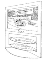
図17は、ワーニング発生部27により生成されるGUIを示す図である。
本実施形態においては、ワーニング発生部27は、出力周波数が72フレーム/秒(フィルムモード)に設定されていて、且つ、映像がインタレース素材である場合に、図17に示すワーニング画像をOSD(On Screen Display)グラフィクスを用いて生成し、出力設定・ワーニングGUI加算部26へ出力する。ワーニング発生部27からワーニング画像のOSDグラフィクスデータを受け付けた出力設定・ワーニングGUI加算部26は、受け付けたOSDグラフィックスデータをスイッチ10から入力される映像信号に付加して、ディジタル変換回路12に出力する。
<Output Setting /
FIG. 17 is a diagram illustrating a GUI generated by the
In the present embodiment, the
これによって、ユーザはフレームが間引かれて不自然な動きの映像信号になる可能性がある事を認識できる。
以上のように本実施形態によれば、接続されている表示装置に、72フレーム/秒での表示を行わせることができる。また、万一インタレース素材を72フレーム/秒(フィルムモード)出力状態で再生して、不自然な動きの映像になったとしても、
ビデオモードへの変更を促すワーニング画像が表示されるため、ユーザは誘導に従ってスムーズに60フレーム/秒(ビデオモード)の出力設定に戻す事ができる。
As a result, the user can recognize that there is a possibility that the frames are thinned out to become an unnatural motion video signal.
As described above, according to the present embodiment, it is possible to cause the connected display device to perform display at 72 frames / second. Also, even if interlaced material is played back at 72 frames per second (film mode) output,
Since a warning image prompting the change to the video mode is displayed, the user can smoothly return to the output setting of 60 frames / second (video mode) according to the guidance.
更に、初期状態では60フレーム/秒(ビデオモード)で出力が設定されている為、ユーザが明示的に72フレーム/秒(フィルムモード)の設定を許可しないと、再生中に72フレーム/秒(フィルムモード)の出力を選択できない構成になっており、かつ72フレーム/秒(フィルムモード)出力許可する際にはGUIにて画面上に注意事項が表示されるので、72フレーム/秒(フィルムモード)出力に関する知識の低いユーザが間違う事も少なくなるという利点がある。 Furthermore, since the output is set at 60 frames / second (video mode) in the initial state, if the user does not explicitly permit the setting of 72 frames / second (film mode), 72 frames / second ( When the output of 72 frames / second (film mode) is permitted, a notice is displayed on the screen on the GUI when enabling the output of 72 frames / second (film mode). ) There is an advantage that users with low knowledge about output are less likely to make mistakes.
(第4実施形態)
第1実施形態〜第3実施形態では、映像信号の入力源が光ディスク1である場合について説明したが、第4実施形態は、映像信号の入力源が放送波である場合の改良である。図18は、映像信号の入力源が放送波等の伝送媒体である場合の再生装置の内部構成を示す図である。本図を図12の内部構成と比較すると、光ピックアップ2、モーター3がアンテナ31、チューナー32に置き換えられている点で相違しており、このアンテナ31、チューナー32が存在する点が新規な改良といえる。
(Fourth embodiment)
In the first to third embodiments, the case where the input source of the video signal is the
受信アンテナ31は、MPEG2方式(ITU−T勧告H.262/ISO/IEC13818−2)で圧縮された映像信号と、その映像信号が順次走査されているか飛び越し走査されているかを示すフラグとが多重された放送波を受信する。
チューナー32は、受信アンテナ31から受信された放送波の選択を行って、選択された放送波を復調回路4に出力する。この出力により復調回路4による復調がなされる。
The receiving
The
以上のように本実施形態によれば、放送波として送信される映像信号に、プログレッシブ映像信号、インタレース映像信号、プルダウン映像信号というような複数種類のフレーム周波数が混在する場合でも、第1実施形態と同様の処理を行うことができるので、第1実施形態と同様の効果を奏することができる。
(第5実施形態)
第1実施形態〜第3実施形態では、映像信号の入力源が光ディスク1である場合について説明したが、第5実施形態は、映像信号の入力源がハードディスクである場合の改良である。図19は、映像信号の入力源がハードディスクである場合の再生装置の内部構成を示す図である。本図を図12の内部構成と比較すると、光ディスク1、光ピックアップ2、モーター3がハードディスク33に置き換えられている点で相違しており、このハードディスク33が存在する点が新規な改良といえる。
As described above, according to the present embodiment, even when a video signal transmitted as a broadcast wave includes a plurality of types of frame frequencies such as a progressive video signal, an interlace video signal, and a pull-down video signal, the first implementation is performed. Since processing similar to that of the embodiment can be performed, the same effect as that of the first embodiment can be obtained.
(Fifth embodiment)
In the first to third embodiments, the case where the input source of the video signal is the
ハードディスク33は、MPEG2方式(ITU−T勧告H.262/ISO/IEC 13818−2)で圧縮されたビデオストリームが記録された内蔵型ディスクであり、第4実施形態に示したアンテナ31、チューナー32を介して、再生装置に入力されてきた映像信号がディジタル状態のまま記録されている。圧縮された映像信号が順次走査されているか飛び越し走査されているかを示すフラグも、このハードディスク33に同時に記録されている。
The
以上のように本実施形態によれば、放送波を通じて伝送され、ハードディスクに蓄積された映像信号に、プログレッシブ映像信号、インタレース映像信号、プルダウン映像信号というような複数種類のフレーム周波数が混在する場合でも、第1実施形態と同様の処理を行うことができるので、第1実施形態と同様の効果を奏することができる。
(備考)
以上、本願の出願時点において、出願人が知り得る最良の実施形態について説明したが、以下に示す技術的トピックについては、更なる改良や変更実施を加えることができる。これらの改良・変更を施すか否かは、何れも任意的であり、実施者の意思によることは留意されたい。
As described above, according to the present embodiment, when a plurality of types of frame frequencies such as a progressive video signal, an interlace video signal, and a pull-down video signal are mixed in a video signal transmitted through a broadcast wave and stored in a hard disk. However, since the same processing as in the first embodiment can be performed, the same effect as in the first embodiment can be obtained.
(Remarks)
As mentioned above, although the best embodiment which an applicant can know was demonstrated at the time of the application of this application, about the technical topic shown below, a further improvement and change implementation can be added. It should be noted that whether or not to make these improvements / changes is arbitrary and depends on the intention of the practitioner.
(制御手順の実現)
各実施形態においてフローチャートを引用して説明した制御手順や、機能的な構成要素による制御手順は、ハードウェア資源を用いて具体的に実現されていることから、自然法則を利用した技術的思想の創作といえ、“プログラムの発明”としての成立要件を満たす。
(Realization of control procedure)
Since the control procedure described with reference to the flowcharts in each embodiment and the control procedure using functional components are specifically realized using hardware resources, the technical idea using the laws of nature is used. It can be said to be a creation, but it meets the requirements for “program invention”.
・本発明に係るプログラムの生産形態
本発明に係るプログラムは、以下のようにして作ることができる。先ず初めに、ソフトウェア開発者は、プログラミング言語を用いて、各フローチャートや、機能的な構成要素を実現するようなソースプログラムを記述する。この記述にあたって、ソフトウェア開発者は、プログラミング言語の構文に従い、クラス構造体や変数、配列変数、外部関数のコールを用いて、各フローチャートや、機能的な構成要素を具現するソースプログラムを記述する。
-Production form of the program according to the present invention The program according to the present invention can be created as follows. First, a software developer uses a programming language to write a source program that implements each flowchart and functional components. In this description, the software developer describes a source program that embodies each flowchart or functional component by using a class structure, a variable, an array variable, or an external function call according to the syntax of the programming language.
記述されたソースプログラムは、ファイルとしてコンパイラに与えられる。コンパイラは、これらのソースプログラムを翻訳してオブジェクトプログラムを生成する。
コンパイラによる翻訳は、構文解析、最適化、資源割付、コード生成といった過程からなる。構文解析では、ソースプログラムの字句解析、構文解析および意味解析を行い、ソースプログラムを中間プログラムに変換する。最適化では、中間プログラムに対して、基本ブロック化、制御フロー解析、データフロー解析という作業を行う。資源割付では、ターゲットとなるプロセッサの命令セットへの適合を図るため、中間プログラム中の変数をターゲットとなるプロセッサのプロセッサが有しているレジスタまたはメモリに割り付ける。コード生成では、中間プログラム内の各中間命令を、プログラムコードに変換し、オブジェクトプログラムを得る。
The described source program is given to the compiler as a file. The compiler translates these source programs to generate an object program.
Translation by the compiler consists of processes such as syntax analysis, optimization, resource allocation, and code generation. In the syntax analysis, lexical analysis, syntax analysis, and semantic analysis of the source program are performed, and the source program is converted into an intermediate program. In the optimization, operations such as basic block formation, control flow analysis, and data flow analysis are performed on the intermediate program. In the resource allocation, in order to adapt to the instruction set of the target processor, a variable in the intermediate program is allocated to a register or memory of the processor of the target processor. In code generation, each intermediate instruction in the intermediate program is converted into a program code to obtain an object program.
ここで生成されたオブジェクトプログラムは、各実施形態に示したフローチャートの各ステップや、機能的構成要素の個々の手順を、コンピュータに実行させるような1つ以上のプログラムコードから構成される。ここでプログラムコードは、プロセッサのネィティブコード、JAVA(登録商標)バイトコードというように、様々な種類がある。プログラムコードによる各ステップの実現には、様々な態様がある。外部関数を利用して、各ステップを実現することができる場合、この外部関数をコールするコール文が、プログラムコードになる。また、1つのステップを実現するようなプログラムコードが、別々のオブジェクトプログラムに帰属することもある。命令種が制限されているRISCプロセッサでは、算術演算命令や論理演算命令、分岐命令等を組合せることで、フローチャートの各ステップを実現してもよい。 The object program generated here is composed of one or more program codes that cause a computer to execute each step of the flowcharts shown in the embodiments and individual procedures of functional components. Here, there are various kinds of program codes such as a processor native code and a JAVA (registered trademark) byte code. There are various modes for realizing each step by the program code. When each step can be realized by using an external function, a call statement that calls the external function becomes a program code. In addition, a program code that realizes one step may belong to different object programs. In a RISC processor in which instruction types are restricted, each step of the flowchart may be realized by combining arithmetic operation instructions, logical operation instructions, branch instructions, and the like.
オブジェクトプログラムが生成されるとプログラマはこれらに対してリンカを起動する。リンカはこれらのオブジェクトプログラムや、関連するライブラリプログラムをメモリ空間に割り当て、これらを1つに結合して、ロードモジュールを生成する。こうして生成されるロードモジュールは、コンピュータによる読み取りを前提にしたものであり、各フローチャートに示した処理手順や機能的な構成要素の処理手順を、コンピュータに実行させるものである。以上の処理を経て、本発明に係るプログラムを作ることができる。 When object programs are generated, the programmer activates the linker for them. The linker allocates these object programs and related library programs to a memory space, and combines them into one to generate a load module. The load module generated in this manner is premised on reading by a computer, and causes the computer to execute the processing procedures and the functional component processing procedures shown in each flowchart. Through the above processing, the program according to the present invention can be created.
・本発明に係るプログラムの使用形態
本発明に係るプログラムは、以下のようにして使用することができる。
(i)組込プログラムとしての使用
本発明に係るプログラムを組込プログラムとして使用する場合、プログラムにあたるロードモジュールを、基本入出力プログラム(BIOS)や、様々なミドルウェア(オペレーションシステム)と共に、命令ROMに書き込む。こうした命令R O Mを、制御部に組み込み、C P Uに実行させることにより、本発明に係るプログラムを、再生装置の制御プログラムとして使用することができる。
-Usage form of the program according to the present invention The program according to the present invention can be used as follows.
(I) Use as an embedded program When the program according to the present invention is used as an embedded program, a load module corresponding to the program is stored in an instruction ROM together with a basic input / output program (BIOS) and various middleware (operation system). Write. By incorporating such an instruction ROM into the control unit and causing the CPU to execute it, the program according to the present invention can be used as a control program for the playback apparatus.
(ii)アプリケーションとしての使用
再生装置が、ハードディスク内蔵モデルである場合は、基本入出力プログラム(BIOS)が命令ROMに組み込まれており、様々なミドルウェア(オペレーションシステム)が、ハードディスクにプレインストールされている。また、ハードディスクから、システムを起動するためのブートROMが、再生装置に設けられている。
(Ii) Use as an application When the playback device is a model with a built-in hard disk, a basic input / output program (BIOS) is built into the instruction ROM, and various middleware (operation system) is preinstalled on the hard disk. Yes. Also, a boot ROM for starting the system from the hard disk is provided in the playback device.
この場合、ロードモジュールのみを、過搬型の記録媒体やネットワークを通じて、再生装置に供給し、1つのアプリケーションとしてハードディスクにインストールする。そうすると、再生装置は、ブートROMによるブートストラップを行い、オペレーションシステムを起動した上で、1つのアプリケーションとして、当該アプリケーションをCPUに実行させ、本発明に係るプログラムを使用する。 In this case, only the load module is supplied to the playback device via a portable recording medium or a network, and is installed on the hard disk as one application. Then, the playback device performs bootstrap using the boot ROM, starts the operation system, causes the CPU to execute the application as one application, and uses the program according to the present invention.
(復調回路4〜スイッチ制御回路19の実現)
各実施形態に示した復調回路4〜スイッチ制御回路19は、それぞれを一個のシステムLSIとして実現することができる。また、復調回路4〜スイッチ制御回路19を一個のシステムLSIとして実現することができる。
システムLSIとは、高密度基板上にベアチップを実装し、パッケージングしたものをいう。複数個のベアチップを高密度基板上に実装し、パッケージングすることにより、あたかも1つのLSIのような外形構造を複数個のベアチップに持たせたものも、システムLSIに含まれる(このようなシステムLSIは、マルチチップモジュールと呼ばれる)。
(Realization of
Each of the
The system LSI means a package in which a bare chip is mounted on a high-density substrate. A system LSI that includes a plurality of bare chips mounted on a high-density substrate and packaged so that the plurality of bare chips have an external structure like one LSI is also included in the system LSI (such a system LSI). LSI is called a multi-chip module).
ここでパッケージの種別に着目するとシステムLSIには、QFP(クワッド フラッド アレイ)、PGA(ピン グリッド アレイ)という種別がある。QFPは、パッケージの四側面にピンが取り付けられたシステムLSIである。PGAは、底面全体に、多くのピンが取り付けられたシステムLSIである。
これらのピンは、他の回路とのインターフェイスとしての役割を担っている。システムLSIにおけるピンには、こうしたインターフェイスの役割が存在するので、システムLSIにおけるこれらのピンに、他の回路を接続することにより、システムLSIは、再生装置の中核としての役割を果たす。
Here, paying attention to the type of package, there are types of system LSIs such as QFP (quad flood array) and PGA (pin grid array). QFP is a system LSI in which pins are attached to four side surfaces of a package. The PGA is a system LSI in which many pins are attached to the entire bottom surface.
These pins serve as an interface with other circuits. Since pins in the system LSI have such an interface role, by connecting other circuits to these pins in the system LSI, the system LSI plays a role as the core of the playback device.
システムLSIにパッケージングされるベアチップは、“フロントエンド部、“バックエンド部”、“デジィタル処理部”からなる。“フロントエンド部”は、アナログ信号を、ディジタル化する部分であり、“バックエンド部”はディジタル処理の結果、得られたデータを、アナログ化して出力する部分である。
各実施形態において内部構成図として示した各構成要素は、このディジタル処理部内に実装される。
The bare chip packaged in the system LSI is composed of a “front end unit, a“ back end unit ”, and a“ digital processing unit. ”The“ front end unit ”is a part that digitizes an analog signal, and“ back end ”. The “part” is a part for converting the data obtained as a result of digital processing into an analog form and outputting it.
Each component shown as an internal configuration diagram in each embodiment is mounted in this digital processing unit.
先に“組込プログラムとしての使用”で述べたように、命令ROMには、プログラムにあたるロードモジュールや、基本入出力プログラム(BIOS)、様々なミドルウェア(オペレーションシステム)が書き込まれる。本実施形態において、特に創作したのは、このプログラムにあたるロードモジュールの部分なので、プログラムにあたるロードモジュールを格納した命令ROMを、ベアチップとしてパッケージングすることにより、本発明に係るシステムLSIは生産することができる。 As described above in “Use as an embedded program”, a load module corresponding to a program, a basic input / output program (BIOS), and various middleware (operation system) are written in the instruction ROM. In this embodiment, since the part of the load module corresponding to this program was created in particular, the system LSI according to the present invention can be produced by packaging the instruction ROM storing the load module corresponding to the program as a bare chip. it can.
具体的な実装については、Soc実装やSip実装を用いることができ望ましい。Soc (Systemonchip)実装とは、1チップ上に複数の回路を焼き付ける技術である。SiP(SysteminPackage)実装とは、複数チップを樹脂等で1パッケージにする技術である。以上の過程を経て、本発明に係るシステムLSIは、各実施形態に示した再生装置の内部構成図を基に作ることができる。 As for specific mounting, Soc mounting or Sip mounting can be used, which is desirable. Soc (system chip) mounting is a technique for printing a plurality of circuits on one chip. SiP (SysteminPackage) mounting is a technology in which a plurality of chips are made into one package with resin or the like. Through the above process, the system LSI according to the present invention can be made based on the internal configuration diagram of the playback device shown in each embodiment.
尚、上述のようにして生成される集積回路は、集積度の違いにより、IC、LSI、スーパーLSI、ウルトラLSIと呼称されることもある。さらに、各再生装置の構成要素の一部又は全てを1つのチップとして構成してもよい。集積回路化は、上述したSoc実装, Sip実装に限るものではなく、専用回路又は汎用プロセスで実現してもよい。LSI製造後に、プログラムすることが可能なFPGA( [ 技術分野] ProgrammableGateArray)や、LSI内部の回路セルの接続や設定を再構成可能なシリコンフィギュラブル・プロセッサを利用することが考えられる。更には、半導体技術の進歩又は派生する技術によりLSIに置き換わる集積回路化の技術が登場すれば、当然、その技術を用いて機能ブロックの集積回路化を行っても良い。例えば、バイオ技術の適応などが可能性としてありうる。 The integrated circuit generated as described above may be called IC, LSI, super LSI, or ultra LSI depending on the degree of integration. Furthermore, some or all of the components of each playback device may be configured as one chip. The circuit integration is not limited to the Soc mounting and the SIP mounting described above, and may be realized by a dedicated circuit or a general-purpose process. It is conceivable to use an FPGA ([Technical Field] ProgrammableGateArray) that can be programmed after manufacturing the LSI, or a silicon configurable processor that can reconfigure the connection and setting of circuit cells inside the LSI. Furthermore, if integrated circuit technology comes out to replace LSI's as a result of the advancement of semiconductor technology or a derivative technology, it is naturally also possible to carry out function block integration using this technology. For example, biotechnology can be applied.
(記録媒体の種類)
第1実施形態では、記録媒体であるディスク1 は、再生専用の光ディスクを一例として説明しているが、記録方式や記録媒体の形態などは限定されるものではない。また光ピックアップ 2 やモーター3 なども、ディスク1 を前提として説明しているため必要な構成であるが、記録媒体の種類や形態が、半導体メモリカード等、他の構成になれば、必要に応じて記録媒体の駆動手段や、記録媒体に対する信号の記録再生手段は、記録媒体に適したものが用いられる。
(Type of recording medium)
In the first embodiment, the
(インタレース映像信号入力時)
第1実施形態におけるハイブリッドモニタ400 、60Hz専用モニタ500 は、明示はしなかったが、インタレース映像信号を表示しうる能力を有している。そして、再生装置における走査変換回路8は、インタレース映像信号の入力時において、これを60Hzプログレッシブ映像信号に変換するのではなく、インタレース映像信号をそのままスルー出力してもよい。
(When interlaced video signal is input)
Although not explicitly shown, the
(フレーム周波数)
第1実施形態乃至5実施形態では、出力映像信号周波数を24フレーム/秒の整数倍と60フレーム/秒である場合について説明を行ったが、本発明は出力映像信号周波数が他の値である場合にも適用可能である。例えば、音声信号と映像信号が同時に送られる放送システムで多用されている60/1.001フレーム/秒と24/1.001フレーム/秒の整数倍とに於いても、本発明の効果は同様に発揮できるものである。
(Frame frequency)
In the first to fifth embodiments, the case where the output video signal frequency is an integer multiple of 24 frames / second and 60 frames / second has been described. However, in the present invention, the output video signal frequency has other values. It is also applicable to cases. For example, the effects of the present invention are the same in 60 / 1.001 frame / second and an integer multiple of 24 / 1.001 frame / second, which are widely used in broadcasting systems in which audio signals and video signals are simultaneously transmitted. It can be demonstrated to.
(映像復調回路6、24Hz−60Hz変換回路7、走査変換回路8、60Hz-24Hz変換回路9、24Hz-48Hz変換回路21、60Hz-48Hz変換回路22、24Hz-72Hz変換回路24、60Hz-72Hz変換回路25)
実施例中のこれら要素の説明中には解像度に関する記述はしておらず、フレーム周波数変換のみ記述しているが、これらの要素が解像度変換機能を持っても、本発明の効果を持つ事ができる。
(
In the description of these elements in the embodiment, there is no description about resolution, and only frame frequency conversion is described. However, even if these elements have a resolution conversion function, the effects of the present invention may be obtained. it can.
例えば、これら要素が、標準画像解像度(縦480−横720画素)の画像をハイビジョン規格解像度(縦1080−横1920画素)に変換する機能を持つ事により、DVDなど標準画像度解像度をもつ映像信号をハイビジョン解像度を持つモニタに出画するようにする事も可能になる。 For example, these elements have a function of converting an image having a standard image resolution (vertical 480-horizontal 720 pixels) into a high-definition standard resolution (vertical 1080-horizontal 1920 pixels), thereby enabling a video signal having a standard image resolution such as a DVD. Can be displayed on a monitor with high-definition resolution.
本発明に係る再生装置は、上記実施形態に内部構成が開示されており、この内部構成に基づき量産することが明らかなので、資質において工業上利用することができる。このことから本発明に係る再生装置は、産業上の利用可能性を有する。 Since the internal configuration of the playback apparatus according to the present invention is disclosed in the above-described embodiment, and it is apparent that mass production will be performed based on this internal configuration, it can be industrially utilized in qualities. Therefore, the playback apparatus according to the present invention has industrial applicability.
1 光ディスク
2 光ピックアップ
2a DVD用ピックアップ
2b BD用ピックアップ
3 モーター
4 復調回路
5 映像種別判別回路
6 映像復調回路
7 24Hz−60Hz変換回路
8 走査変換回路
9 60Hz−24Hz変換回路
11 GUI加算部
11 出力設定GUI加算部
12 ディジタル変換回路
13 HDMI端子
14 表示能力判定部
15 再生設定部
16 モード設定部
17 モード設定GUI生成部
18 出力周波数設定部
19 スイッチ制御回路
20 表示周波数指示部
21 24Hz−48Hz変換回路
22 60Hz−48Hz変換回路
23 表示周波数指示部
24 24Hz−72Hz変換回路
25 60Hz−72Hz変換回路
26 ワーニングGUI加算部
27 ワーニング発生部
31 受信アンテナ
32 チューナー
33 ハードディスク
200 再生装置
300 リモコン
400 ハイブリッドモニタ
500 60Hz専用モニタ
DESCRIPTION OF
Claims (12)
(a)出力する映像信号のフレーム周波数を前記第1フレーム周波数に固定する固定モードと、(b)出力する映像信号のフレーム周波数を前記第1フレーム周波数か前記第2フレーム周波数かに変更できる可変モードとの何れかを、ユーザの選択に応じて、自装置の動作モードとして設定するモード設定手段と、
前記混在映像信号の第1フレーム周波数期間の映像信号を第1フレーム周波数のまま出力し、第2フレーム周波数期間の映像信号を第1フレーム周波数の映像信号に変換して出力する第1態様の映像出力と、前記混在映像信号の第2フレーム周波数期間の映像信号を第2フレーム周波数のまま出力し、第1フレーム周波数期間の映像信号を第2フレーム周波数の映像信号に変換して出力する第2態様の映像出力とを、選択的に切り替える切替手段と、
前記動作モードが可変モードに設定された状態で、前記表示装置へ映像信号を出力している期間において、出力する映像信号のフレーム周波数を前記第1フレーム周波数及び前記第2フレーム周波数の何れか一方から他方に変更する旨の指示をユーザから受け付ける変更受付手段とを備え、
前記切替手段は、出力する映像信号のフレーム周波数を第2フレーム周波数に変更する旨の指示が受け付けられた場合、実行中の映像出力を前記第1態様の映像出力から第2態様の映像出力へ切り替え、出力する映像信号のフレーム周波数を第1フレーム周波数に変更する旨の指示が受け付けられた場合、実行中の映像出力を前記第2態様の映像出力から第1態様の映像出力へ切り替える
ことを特徴とする再生装置。 A playback apparatus that outputs a mixed video signal in which a period in which the frame frequency is the first frame frequency and a period in which the second frame frequency is mixed to the display apparatus,
(a) a fixed mode in which the frame frequency of the output video signal is fixed to the first frame frequency; and (b) a variable that can change the frame frequency of the output video signal to the first frame frequency or the second frame frequency. Mode setting means for setting one of the modes as an operation mode of the own device according to the user's selection;
The video of the first mode in which the video signal in the first frame frequency period of the mixed video signal is output as the first frame frequency, and the video signal in the second frame frequency period is converted into the video signal of the first frame frequency and output. The output and the video signal of the second frame frequency period of the mixed video signal are output as the second frame frequency, and the video signal of the first frame frequency period is converted into a video signal of the second frame frequency and output. Switching means for selectively switching the video output of the aspect;
In a state in which the operation mode is set to the variable mode and the video signal is output to the display device, the frame frequency of the video signal to be output is one of the first frame frequency and the second frame frequency. Change accepting means for accepting an instruction from the user to change from one to the other,
When an instruction to change the frame frequency of the video signal to be output to the second frame frequency is received, the switching unit changes the video output being executed from the video output of the first mode to the video output of the second mode. When an instruction to change the frame frequency of the video signal to be switched and output to the first frame frequency is received, the video output being executed is switched from the video output of the second mode to the video output of the first mode. A playback device.
前記モード設定手段は、前記グラフィクスユーザインターフェイスを介して、固定モード及び可変モードの何れかの選択をユーザから受け付ける
ことを特徴とする請求項1に記載の再生装置。 A graphics user interface is generated to warn the user that there is a possibility that the display on the display device may be disturbed when the video signal having the first frame frequency is output in the variable mode, and to prompt the user to select an operation mode. Further comprising a GUI generating means for displaying
The playback apparatus according to claim 1, wherein the mode setting unit receives a selection of a fixed mode or a variable mode from the user via the graphics user interface.
前記変更受付手段は、前記受付用グラフィクスユーザインターフェイスを介して、前記変更指示を受け付ける
ことを特徴とする請求項2に記載の再生装置。 The GUI generating means further includes an accepting graphics user interface for requesting whether to output the frame frequency to the first frame frequency or the second frame frequency when the operation mode is set to the variable mode. , Generating according to the user's request made during the period of outputting the video signal to the display device,
The playback apparatus according to claim 2, wherein the change accepting unit accepts the change instruction via the accepting graphics user interface.
前記第1画面状態では、出力する映像信号を前記第1フレーム周波数に変更する指示を受け付け、
前記第2画面状態では、出力する映像信号を前記第2フレーム周波数に変更する指示を受け付ける
ことを特徴とする請求項3に記載の再生装置。 The reception graphics user interface has two screen states, a first screen state and a second screen state that are switched according to a user operation, and is generated in the first screen state when generated by the GUI generation unit,
In the first screen state, an instruction to change the output video signal to the first frame frequency is received,
The playback apparatus according to claim 3, wherein in the second screen state, an instruction to change an output video signal to the second frame frequency is received.
ことを特徴とする請求項2に記載の再生装置。 The GUI generation means further includes a graphics user interface that warns the user that the display on the display device may be disturbed, and the operation mode is set to the variable mode, and the GUI user interface 3. The playback apparatus according to claim 2, wherein the video signal is generated during a period in which the video signal is converted into a video signal having the second frame frequency and output, and is displayed on the display device.
前記第1フレーム周波数期間の映像信号に重複フィールドが含まれる場合、前記第1フレーム周波数期間における映像信号のうち、1の重複フィールドの次のフィールドから前記1の重複フィールドの次の重複フィールドまでを、2つのフレームを構成するフィールドに分類する走査変換回路と、
前記混在映像信号の第1フレーム周波数期間の映像信号を第2フレーム周波数の映像信号に変換する際に、前記走査変換回路において前記2つのフレームを構成するものとして分類したフィールド群を、前記第2フレーム周波数の映像信号の2つのフレームに変換するフレーム周波数変換回路とを更に備える
ことを特徴とする請求項1に記載の再生装置。 A video type determination circuit for determining whether or not an overlapping field is included in the video signal in the first frame frequency period of the mixed video signal;
If the video signal in the first frame frequency period includes an overlapping field, the video signal in the first frame frequency period is from the next field after one overlapping field to the next overlapping field after the first overlapping field. A scan conversion circuit for classifying the fields into two frames;
When converting the video signal of the mixed video signal in the first frame frequency period into the video signal of the second frame frequency, the field group classified as constituting the two frames in the scan conversion circuit is the second group. The playback apparatus according to claim 1, further comprising a frame frequency conversion circuit that converts the video signal having the frame frequency into two frames.
前記モード設定手段による前記設定は、前記判定手段において、前記表示装置が両方の表示能力を具備していると判定された場合になされる。
ことを特徴とする請求項1に記載の再生装置。 The display device to be connected has only the first display capability capable of displaying the video signal of the first frame frequency, or the first display capability and the video signal of the second frame frequency. A determination means for determining whether both of the second display capabilities that can be displayed are provided;
The setting by the mode setting unit is performed when the determination unit determines that the display device has both display capabilities.
The reproducing apparatus according to claim 1.
前記判定手段は、前記所定のインターフェイスを介して、映像規格に関する情報を、前記表示装置から取り出して、当該映像規格に関する情報に基づき前記判定を行う
ことを特徴とする請求項7に記載の再生装置。 The playback device is connected to a display device via a predetermined interface,
8. The playback apparatus according to claim 7, wherein the determination unit extracts information related to a video standard from the display device via the predetermined interface, and performs the determination based on the information related to the video standard. .
記録された映像情報の読み出しにより第1フレーム周波数及び第2フレーム周波数の何れかのフレーム周波数の映像信号が得られる第2の種類の記録媒体に係る第2読出手段とを更に備え、
前記モード設定手段による設定、及び、前記変更受付手段による受け付けは、前記第1読出手段により映像情報が読み出された場合に実行される
ことを特徴とする請求項1に記載の再生装置。 First reading means according to a first type of recording medium from which a mixed video signal can be obtained by reading recorded video information;
A second reading means according to a second type of recording medium that can obtain a video signal of any one of the first frame frequency and the second frame frequency by reading the recorded video information;
2. The playback apparatus according to claim 1, wherein the setting by the mode setting unit and the reception by the change receiving unit are executed when video information is read by the first reading unit.
(a)出力する映像信号のフレーム周波数を前記第1フレーム周波数に固定する固定モードと、(b)出力する映像信号のフレーム周波数を前記第1フレーム周波数か前記第2フレーム周波数の整数倍の第3フレーム周波数かに変更できる可変モードとの何れかを、ユーザの選択に応じて、自装置の動作モードとして設定するモード設定手段と、
前記混在映像信号の第1フレーム周波数期間の映像信号を第1フレーム周波数のまま出力し、第2フレーム周波数期間の映像信号を第1フレーム周波数の映像信号に変換して出力する第1態様の映像出力と、前記第3フレーム周波数での表示を表示装置に命じた上で、前記混在映像信号の第1フレーム周波数期間の映像信号、及び、第2フレーム周波数期間の映像信号を、前記第3フレーム周波数の映像信号に変換して出力する第2態様の映像出力とを切り替える切替手段と、
前記動作モードが可変モードに設定された状態で、前記表示装置へ映像信号を出力している期間において、出力する映像信号のフレーム周波数を前記第1フレーム周波数及び前記第3フレーム周波数の何れか一方から他方に変更する旨の指示をユーザから受け付ける変更受付手段とを備え、
前記切替手段は、出力する映像信号のフレーム周波数を第3フレーム周波数に変更する旨の指示が受け付けられた場合、実行中の映像出力を前記第1態様の映像出力から第2態様の映像出力へ切り替え、出力する映像信号のフレーム周波数を第1フレーム周波数に変更する旨の指示が受け付けられた場合、実行中の映像出力を前記第2態様の映像出力から第1態様の映像出力へ切り替える
ことを特徴とする再生装置。 A playback apparatus that outputs a mixed video signal in which a period in which the frame frequency is the first frame frequency and a period in which the second frame frequency is mixed to the display apparatus,
(a) a fixed mode in which the frame frequency of the video signal to be output is fixed to the first frame frequency; and (b) the frame frequency of the video signal to be output is the first frame frequency or an integer multiple of the second frame frequency. Mode setting means for setting any one of the variable modes that can be changed to the three-frame frequency as an operation mode of the own device according to a user's selection;
The video of the first mode in which the video signal in the first frame frequency period of the mixed video signal is output as the first frame frequency, and the video signal in the second frame frequency period is converted into the video signal of the first frame frequency and output. Instructing the display device to output and display at the third frame frequency, the video signal in the first frame frequency period and the video signal in the second frame frequency period of the mixed video signal are transmitted to the third frame. Switching means for switching between the video output of the second mode to be converted into a video signal of frequency and output;
In a state where the operation mode is set to the variable mode and the video signal is output to the display device, the frame frequency of the video signal to be output is one of the first frame frequency and the third frame frequency. Change accepting means for accepting an instruction from the user to change from one to the other,
When an instruction to change the frame frequency of the video signal to be output to the third frame frequency is received, the switching unit changes the video output being executed from the video output of the first mode to the video output of the second mode. When an instruction to change the frame frequency of the video signal to be switched and output to the first frame frequency is received, the video output being executed is switched from the video output of the second mode to the video output of the first mode. A playback device.
第1フレーム周波数、及び第2フレーム周波数の映像信号を、フレーム周波数が24Hzの整数倍の映像信号に変換して出力するフレーム周波数変換回路を更に備える
ことを特徴とする請求項10に記載の再生装置。 The third frame frequency is an integer multiple of 24 Hz,
11. The reproduction according to claim 10, further comprising a frame frequency conversion circuit for converting the video signal having the first frame frequency and the second frame frequency into a video signal having an integer multiple of 24 Hz and outputting the video signal. apparatus.
前記再生装置は、前記混在映像信号の第1フレーム周波数期間の映像信号を第1フレーム周波数のまま出力し、第2フレーム周波数期間の映像信号を第1フレーム周波数の映像信号に変換して出力する第1態様の映像出力と、前記混在映像信号の第2フレーム周波数期間の映像信号を第2フレーム周波数のまま出力し、第1フレーム周波数期間の映像信号を第2フレーム周波数の映像信号に変換して出力する第2態様の映像出力とを、選択的に切り替える切替手段を備え、
前記再生方法は、
(a)出力する映像信号のフレーム周波数を前記第1フレーム周波数に固定する固定モードと、(b)出力する映像信号のフレーム周波数を前記第1フレーム周波数か前記第2フレーム周波数かに変更できる可変モードとの何れかを、ユーザの選択に応じて、前記再生装置の動作モードとして設定するモード設定ステップと、
前記動作モードを可変モードに設定した状態で、前記再生装置から前記表示装置へ映像信号を出力している期間において、出力する映像信号のフレーム周波数を前記第1フレーム周波数及び前記第2フレーム周波数の何れか一方から他方に変更する旨の指示をユーザから受け付ける変更受付ステップと、
出力する映像信号のフレーム周波数を第2フレーム周波数に変更する旨の指示が受け付けられた場合、前記切替手段が実行中の映像出力を前記第1態様の映像出力から第2態様の映像出力へ切り替え、出力する映像信号のフレーム周波数を第1フレーム周波数に変更する旨の指示が受け付けられた場合、前記切替手段が実行中の映像出力を前記第2態様の映像出力から第1態様の映像出力へ切り替える切替ステップと
を含むことを特徴とする再生方法。 A playback method in a playback apparatus that outputs a mixed video signal in which a period in which a frame frequency is a first frame frequency and a period in which a second frame frequency is mixed to a display apparatus,
The playback apparatus outputs the video signal of the mixed video signal in the first frame frequency period as it is at the first frame frequency, converts the video signal of the second frame frequency period into a video signal of the first frame frequency, and outputs the video signal. The video output of the first mode and the video signal in the second frame frequency period of the mixed video signal are output as the second frame frequency, and the video signal in the first frame frequency period is converted to the video signal of the second frame frequency. Switching means for selectively switching the video output of the second mode to be output
The playback method is:
(a) a fixed mode in which the frame frequency of the output video signal is fixed to the first frame frequency; and (b) a variable that can change the frame frequency of the output video signal to the first frame frequency or the second frame frequency. A mode setting step of setting any of the modes as an operation mode of the playback device in accordance with a user's selection;
With the operation mode set to the variable mode, the frame frequency of the video signal to be output is equal to the first frame frequency and the second frame frequency in a period in which the video signal is output from the playback device to the display device. A change acceptance step for accepting an instruction from the user to change from either one to the other;
When an instruction to change the frame frequency of the video signal to be output to the second frame frequency is received, the video output being executed by the switching unit is switched from the video output of the first mode to the video output of the second mode. When an instruction to change the frame frequency of the video signal to be output to the first frame frequency is received, the video output being executed by the switching unit is changed from the video output of the second mode to the video output of the first mode. And a switching step for switching.
Priority Applications (1)
| Application Number | Priority Date | Filing Date | Title |
|---|---|---|---|
| JP2009007696A JP5155203B2 (en) | 2008-01-22 | 2009-01-16 | Playback device and playback method |
Applications Claiming Priority (3)
| Application Number | Priority Date | Filing Date | Title |
|---|---|---|---|
| JP2008011251 | 2008-01-22 | ||
| JP2008011251 | 2008-01-22 | ||
| JP2009007696A JP5155203B2 (en) | 2008-01-22 | 2009-01-16 | Playback device and playback method |
Publications (2)
| Publication Number | Publication Date |
|---|---|
| JP2009201100A JP2009201100A (en) | 2009-09-03 |
| JP5155203B2 true JP5155203B2 (en) | 2013-03-06 |
Family
ID=40876577
Family Applications (1)
| Application Number | Title | Priority Date | Filing Date |
|---|---|---|---|
| JP2009007696A Active JP5155203B2 (en) | 2008-01-22 | 2009-01-16 | Playback device and playback method |
Country Status (2)
| Country | Link |
|---|---|
| US (1) | US8111977B2 (en) |
| JP (1) | JP5155203B2 (en) |
Cited By (1)
| Publication number | Priority date | Publication date | Assignee | Title |
|---|---|---|---|---|
| US9770952B2 (en) | 2011-12-05 | 2017-09-26 | Compagnie Generale Des Etablissements Michelin | Noise-reducing device for a tire |
Families Citing this family (8)
| Publication number | Priority date | Publication date | Assignee | Title |
|---|---|---|---|---|
| JP4936570B2 (en) * | 2009-09-30 | 2012-05-23 | キヤノン株式会社 | Digital broadcast receiving apparatus and control method thereof |
| CN102598657B (en) * | 2009-10-27 | 2015-03-25 | 佳能株式会社 | Video playback device and control method for a video playback device |
| US8576336B2 (en) | 2009-12-09 | 2013-11-05 | Thomson Licensing | Progressive video reformatting for film-based content |
| JP2011197215A (en) * | 2010-03-18 | 2011-10-06 | Seiko Epson Corp | Image processing device, display system, electronic apparatus, and image processing method |
| US9275603B2 (en) * | 2012-04-23 | 2016-03-01 | Intel Corporation | Driving displays at cinematic frame rates |
| JPWO2017086218A1 (en) * | 2015-11-17 | 2018-09-13 | 株式会社日立国際電気 | Camera control device and television camera |
| US10979744B2 (en) * | 2017-11-03 | 2021-04-13 | Nvidia Corporation | Method and system for low latency high frame rate streaming |
| US11025858B2 (en) * | 2019-08-08 | 2021-06-01 | Netflix, Inc. | Frame rate conversion |
Family Cites Families (10)
| Publication number | Priority date | Publication date | Assignee | Title |
|---|---|---|---|---|
| JP2001117539A (en) | 1999-10-14 | 2001-04-27 | Nec Corp | Method of reproducing moving picture and system using the same |
| JP2003324644A (en) * | 2002-05-07 | 2003-11-14 | Canon Inc | Video signal processing apparatus, image display control method, storage medium and program |
| JP2004159191A (en) * | 2002-11-07 | 2004-06-03 | Seiko Epson Corp | Conversion of frame rate in accordance with image data |
| US7420618B2 (en) * | 2003-12-23 | 2008-09-02 | Genesis Microchip Inc. | Single chip multi-function display controller and method of use thereof |
| US20080018787A1 (en) * | 2004-04-01 | 2008-01-24 | Hopper William R | Method and Apparatus for Producing Images |
| JP4349249B2 (en) * | 2004-10-06 | 2009-10-21 | 株式会社日立製作所 | Image reproducing apparatus and image reproducing method |
| JP4224493B2 (en) * | 2005-01-13 | 2009-02-12 | パナソニック株式会社 | Playback device, program, and playback method |
| US7826710B2 (en) * | 2005-01-13 | 2010-11-02 | Panasonic Corporation | Playback device, computer program, playback method |
| US8200062B2 (en) * | 2006-04-21 | 2012-06-12 | Panasonic Corporation | Playback apparatus, program, and playback method |
| JP4340304B2 (en) * | 2006-04-21 | 2009-10-07 | パナソニック株式会社 | Playback device, program, and playback method |
-
2009
- 2009-01-16 JP JP2009007696A patent/JP5155203B2/en active Active
- 2009-01-21 US US12/356,760 patent/US8111977B2/en active Active
Cited By (1)
| Publication number | Priority date | Publication date | Assignee | Title |
|---|---|---|---|---|
| US9770952B2 (en) | 2011-12-05 | 2017-09-26 | Compagnie Generale Des Etablissements Michelin | Noise-reducing device for a tire |
Also Published As
| Publication number | Publication date |
|---|---|
| US8111977B2 (en) | 2012-02-07 |
| JP2009201100A (en) | 2009-09-03 |
| US20090185795A1 (en) | 2009-07-23 |
Similar Documents
| Publication | Publication Date | Title |
|---|---|---|
| JP5155203B2 (en) | Playback device and playback method | |
| US8467665B2 (en) | Playback device, computer program, playback method | |
| CN106105177B (en) | Transform method and converting means | |
| JP7117626B2 (en) | Video display device and video display method | |
| CN101060603B (en) | Playback apparatus, program, and playback method | |
| CN110460744A (en) | Luminance transformation device and luminance transformation method | |
| WO2019069482A1 (en) | Image display system and image display method | |
| JP4340304B2 (en) | Playback device, program, and playback method | |
| US20110167465A1 (en) | Device control apparatus, device control method and computer program | |
| JP2012213131A (en) | Input switching device | |
| JP2017050840A (en) | Conversion method and conversion device | |
| JP4224493B2 (en) | Playback device, program, and playback method | |
| US7173669B2 (en) | Digital television system and method for supporting a film mode | |
| CN102982818B (en) | System and method which are capable of achieving player audio return | |
| JP4738524B2 (en) | Information processing apparatus and video reproduction method | |
| KR100925433B1 (en) | DVD decoder | |
| US20040130663A1 (en) | Method and apparatus for outputting video signal of composite image apparatus | |
| US8374493B2 (en) | Playback apparatus | |
| JP5275402B2 (en) | Information processing apparatus, video playback method, and video playback program | |
| WO2017037971A1 (en) | Conversion method and conversion apparatus | |
| JP2002247520A (en) | Video signal output device | |
| JP2011182303A (en) | Audio control apparatus and audio control system |
Legal Events
| Date | Code | Title | Description |
|---|---|---|---|
| A621 | Written request for application examination |
Free format text: JAPANESE INTERMEDIATE CODE: A621 Effective date: 20110630 |
|
| A977 | Report on retrieval |
Free format text: JAPANESE INTERMEDIATE CODE: A971007 Effective date: 20121029 |
|
| TRDD | Decision of grant or rejection written | ||
| A01 | Written decision to grant a patent or to grant a registration (utility model) |
Free format text: JAPANESE INTERMEDIATE CODE: A01 Effective date: 20121113 |
|
| A61 | First payment of annual fees (during grant procedure) |
Free format text: JAPANESE INTERMEDIATE CODE: A61 Effective date: 20121206 |
|
| FPAY | Renewal fee payment (event date is renewal date of database) |
Free format text: PAYMENT UNTIL: 20151214 Year of fee payment: 3 |
|
| R150 | Certificate of patent or registration of utility model |
Ref document number: 5155203 Country of ref document: JP Free format text: JAPANESE INTERMEDIATE CODE: R150 Free format text: JAPANESE INTERMEDIATE CODE: R150 |