JP5149268B2 - Rotation angle sensor mounting structure and variable valve operating apparatus for internal combustion engine using the same structure - Google Patents
Rotation angle sensor mounting structure and variable valve operating apparatus for internal combustion engine using the same structure Download PDFInfo
- Publication number
- JP5149268B2 JP5149268B2 JP2009295156A JP2009295156A JP5149268B2 JP 5149268 B2 JP5149268 B2 JP 5149268B2 JP 2009295156 A JP2009295156 A JP 2009295156A JP 2009295156 A JP2009295156 A JP 2009295156A JP 5149268 B2 JP5149268 B2 JP 5149268B2
- Authority
- JP
- Japan
- Prior art keywords
- rotation angle
- sensor
- angle sensor
- shaft
- internal combustion
- Prior art date
- Legal status (The legal status is an assumption and is not a legal conclusion. Google has not performed a legal analysis and makes no representation as to the accuracy of the status listed.)
- Expired - Fee Related
Links
- 238000002485 combustion reaction Methods 0.000 title claims description 31
- 230000009467 reduction Effects 0.000 claims description 66
- 238000001514 detection method Methods 0.000 claims description 21
- 230000008859 change Effects 0.000 claims description 4
- 230000007246 mechanism Effects 0.000 description 21
- 239000000446 fuel Substances 0.000 description 10
- 230000002093 peripheral effect Effects 0.000 description 8
- 230000005540 biological transmission Effects 0.000 description 6
- 239000004575 stone Substances 0.000 description 4
- 230000008878 coupling Effects 0.000 description 3
- 238000010168 coupling process Methods 0.000 description 3
- 238000005859 coupling reaction Methods 0.000 description 3
- 230000004308 accommodation Effects 0.000 description 2
- 239000002828 fuel tank Substances 0.000 description 2
- 238000004891 communication Methods 0.000 description 1
- 238000002347 injection Methods 0.000 description 1
- 239000007924 injection Substances 0.000 description 1
- 230000002452 interceptive effect Effects 0.000 description 1
- 238000012423 maintenance Methods 0.000 description 1
- 239000000463 material Substances 0.000 description 1
- 230000000149 penetrating effect Effects 0.000 description 1
- 238000007493 shaping process Methods 0.000 description 1
- 238000004804 winding Methods 0.000 description 1
Images


Classifications
-
- F—MECHANICAL ENGINEERING; LIGHTING; HEATING; WEAPONS; BLASTING
- F02—COMBUSTION ENGINES; HOT-GAS OR COMBUSTION-PRODUCT ENGINE PLANTS
- F02B—INTERNAL-COMBUSTION PISTON ENGINES; COMBUSTION ENGINES IN GENERAL
- F02B61/00—Adaptations of engines for driving vehicles or for driving propellers; Combinations of engines with gearing
- F02B61/02—Adaptations of engines for driving vehicles or for driving propellers; Combinations of engines with gearing for driving cycles
-
- F—MECHANICAL ENGINEERING; LIGHTING; HEATING; WEAPONS; BLASTING
- F01—MACHINES OR ENGINES IN GENERAL; ENGINE PLANTS IN GENERAL; STEAM ENGINES
- F01L—CYCLICALLY OPERATING VALVES FOR MACHINES OR ENGINES
- F01L1/00—Valve-gear or valve arrangements, e.g. lift-valve gear
- F01L1/46—Component parts, details, or accessories, not provided for in preceding subgroups
-
- F—MECHANICAL ENGINEERING; LIGHTING; HEATING; WEAPONS; BLASTING
- F01—MACHINES OR ENGINES IN GENERAL; ENGINE PLANTS IN GENERAL; STEAM ENGINES
- F01L—CYCLICALLY OPERATING VALVES FOR MACHINES OR ENGINES
- F01L13/00—Modifications of valve-gear to facilitate reversing, braking, starting, changing compression ratio, or other specific operations
- F01L13/0015—Modifications of valve-gear to facilitate reversing, braking, starting, changing compression ratio, or other specific operations for optimising engine performances by modifying valve lift according to various working parameters, e.g. rotational speed, load, torque
- F01L13/0021—Modifications of valve-gear to facilitate reversing, braking, starting, changing compression ratio, or other specific operations for optimising engine performances by modifying valve lift according to various working parameters, e.g. rotational speed, load, torque by modification of rocker arm ratio
-
- F—MECHANICAL ENGINEERING; LIGHTING; HEATING; WEAPONS; BLASTING
- F01—MACHINES OR ENGINES IN GENERAL; ENGINE PLANTS IN GENERAL; STEAM ENGINES
- F01L—CYCLICALLY OPERATING VALVES FOR MACHINES OR ENGINES
- F01L13/00—Modifications of valve-gear to facilitate reversing, braking, starting, changing compression ratio, or other specific operations
- F01L13/0015—Modifications of valve-gear to facilitate reversing, braking, starting, changing compression ratio, or other specific operations for optimising engine performances by modifying valve lift according to various working parameters, e.g. rotational speed, load, torque
- F01L13/0063—Modifications of valve-gear to facilitate reversing, braking, starting, changing compression ratio, or other specific operations for optimising engine performances by modifying valve lift according to various working parameters, e.g. rotational speed, load, torque by modification of cam contact point by displacing an intermediate lever or wedge-shaped intermediate element, e.g. Tourtelot
- F01L2013/0073—Modifications of valve-gear to facilitate reversing, braking, starting, changing compression ratio, or other specific operations for optimising engine performances by modifying valve lift according to various working parameters, e.g. rotational speed, load, torque by modification of cam contact point by displacing an intermediate lever or wedge-shaped intermediate element, e.g. Tourtelot with an oscillating cam acting on the valve of the "Delphi" type
-
- F—MECHANICAL ENGINEERING; LIGHTING; HEATING; WEAPONS; BLASTING
- F01—MACHINES OR ENGINES IN GENERAL; ENGINE PLANTS IN GENERAL; STEAM ENGINES
- F01L—CYCLICALLY OPERATING VALVES FOR MACHINES OR ENGINES
- F01L2820/00—Details on specific features characterising valve gear arrangements
- F01L2820/04—Sensors
- F01L2820/041—Camshafts position or phase sensors
Landscapes
- Engineering & Computer Science (AREA)
- Mechanical Engineering (AREA)
- General Engineering & Computer Science (AREA)
- Chemical & Material Sciences (AREA)
- Combustion & Propulsion (AREA)
- Valve-Gear Or Valve Arrangements (AREA)
- Valve Device For Special Equipments (AREA)
- Measurement Of Length, Angles, Or The Like Using Electric Or Magnetic Means (AREA)
Description
本発明は、回転角センサ取り付け構造及び同構造を用いた内燃機関の可変動弁装置に関する。 The present invention relates to a rotation angle sensor mounting structure and a variable valve operating apparatus for an internal combustion engine using the structure.
従来、内燃機関の可変動弁装置に設けられた回転角センサ取り付け構造では、被回転角検出対象軸が軸の両端の2箇所の軸受けで支持され、この軸の回転角を検出する回転角センサは、被回転角検出対象軸の端部に連結されていた(例えば、特許文献1参照)。 2. Description of the Related Art Conventionally, in a rotation angle sensor mounting structure provided in a variable valve device for an internal combustion engine, a rotation angle detection target shaft is supported by two bearings at both ends of the shaft and detects the rotation angle of this shaft. Is connected to the end of the rotation angle detection target shaft (see, for example, Patent Document 1).
ところで、上記のような回転角センサ取り付け構造では、被回転角検出対象軸が複数回回転する構成において、1回転(360°)以内の検出範囲の回転角センサを用いる場合には、被回転角検出対象軸の回転を減速させるリダクションギヤが必要となる。このリダクションギヤを設ける構成としては、リダクションギヤの軸方向の両端を軸受け等でそれぞれ支持することが考えられるが、この場合、リダクションギヤを支持するために、被回転角検出対象軸の軸方向にスペースを確保する必要があった。
本発明は、上述した事情に鑑みてなされたものであり、回転角センサ取り付け構造を小型化できるようにすることを目的とする。
By the way, in the rotation angle sensor mounting structure as described above, when a rotation angle sensor within a detection range within one rotation (360 °) is used in a configuration in which the rotation angle detection target shaft rotates a plurality of times, the rotation angle sensor A reduction gear that decelerates the rotation of the detection target shaft is required. As a configuration in which this reduction gear is provided, it is conceivable to support both ends of the reduction gear in the axial direction with bearings or the like. In this case, in order to support the reduction gear, in the axial direction of the rotation angle detection target shaft. It was necessary to secure space.
The present invention has been made in view of the above-described circumstances, and an object of the present invention is to reduce the size of the rotation angle sensor mounting structure.
上記目的を達成するため、本発明は、被回転角検出対象軸の回転をリダクションギヤを介して検出する回転角センサ取り付け構造において、前記リダクションギヤの中央部にベアリングのアウタレースを圧入固定し、前記ベアリングのインナレースをボルトによって支持壁に固定すると共に、前記リダクションギヤの側面に前記ボルトの頭部を跨ぐ回転角センサの取り付け支持部を一体に固定したことを特徴とする。
この構成によれば、ベアリングのアウタレースをリダクションギヤに圧入し、インナレースをボルトによって支持壁に固定すると共に、リダクションギヤの側面に回転角センサの取り付け支持部を一体に固定したため、リダクションギヤの取り付けのためのベアリングが一つで済む。これにより、リダクションギヤを取り付けるために大きなスペースが必要ないため、回転角センサ取り付け構造を被回転角検出対象軸の軸方向に小型化できる。また、ベアリングが一つで済むため、部品点数を削減できる。さらに、回転角センサの取り付け支持部をリダクションギヤの側面に一体に固定したため、回転角センサ取り付け構造を軸方向に小型化できる。
In order to achieve the above object, the present invention provides a rotation angle sensor mounting structure for detecting rotation of a rotation angle detection target shaft via a reduction gear, wherein a bearing outer race is press-fitted and fixed to a central portion of the reduction gear, The inner race of the bearing is fixed to a support wall by a bolt, and a mounting support portion of a rotation angle sensor straddling the head of the bolt is integrally fixed to a side surface of the reduction gear.
According to this configuration, the outer race of the bearing is press-fitted into the reduction gear, the inner race is fixed to the support wall with the bolt, and the attachment support portion of the rotation angle sensor is integrally fixed to the side surface of the reduction gear. Only one bearing is needed. Thereby, since a large space is not required for mounting the reduction gear, the rotation angle sensor mounting structure can be downsized in the axial direction of the rotation angle detection target shaft. Moreover, since only one bearing is required, the number of parts can be reduced. Furthermore, since the attachment support part of the rotation angle sensor is integrally fixed to the side surface of the reduction gear, the rotation angle sensor attachment structure can be miniaturized in the axial direction.
また、上記構成において、前記回転角センサはポテンショメータである構成としても良い。
この場合、安価なポテンショメータを用いて被回転角検出対象軸の回転角を検出できる。
In the above configuration, the rotation angle sensor may be a potentiometer.
In this case, the rotation angle of the rotation angle detection target shaft can be detected using an inexpensive potentiometer.
また、本発明は、上記回転角センサ取り付け構造を用いるとともに、シリンダヘッド側面に設けたアクチュエータにより前記アクチュエータと平行に設けた回転軸を駆動してバルブの位相及び/またはリフト量を変化させ、前記回転軸は前記被回転角検出対象軸とし、前記回転軸の端部に前記リダクションギヤの駆動ギヤを設け、前記回転角センサは前記回転軸と直交するシリンダヘッド側面に設けたことを特徴とする内燃機関の可変動弁装置を提供する。
この構成によれば、アクチュエータを回転軸と平行にシリンダヘッドの側面に設け、回転角センサを回転軸と直交するシリンダヘッド側面に設けたため、アクチュエータ及び回転角センサが他の部品の配置の邪魔にならないと共に、アクチュエータ及び回転角センサをコンパクトに配置できる。
In addition, the present invention uses the rotation angle sensor mounting structure described above and drives a rotating shaft provided in parallel with the actuator by an actuator provided on the side surface of the cylinder head to change the phase and / or lift amount of the valve. The rotation axis is the rotation angle detection target axis, the reduction gear drive gear is provided at the end of the rotation axis, and the rotation angle sensor is provided on the side surface of the cylinder head perpendicular to the rotation axis. A variable valve operating apparatus for an internal combustion engine is provided.
According to this configuration, since the actuator is provided on the side surface of the cylinder head in parallel with the rotation axis, and the rotation angle sensor is provided on the side surface of the cylinder head orthogonal to the rotation axis, the actuator and the rotation angle sensor obstruct the arrangement of other components. In addition, the actuator and the rotation angle sensor can be arranged in a compact manner.
また、上記構成において、前記内燃機関は、シリンダをV字型に配置したV型内燃機関であって、前記アクチュエータは前後シリンダの反オフセット側に配置されても良い。
この場合、アクチュエータが、シリンダの反オフセット側に配置されるため、アクチュエータをコンパクトに配置でき、内燃機関の横幅を小さく抑えることができる。
さらに、前記回転角センサは、Vバンクの内側に配置されても良い。
この場合、回転角センサがVバンクの内側に配置されるため、回転角センサを他の部品の配置の邪魔にならないようにコンパクトに配置できる。
また、前記内燃機関は、車体の前後方向に前記Vバンクを配置した自動二輪車の内燃機関であっても良い。
この場合、自動二輪車の前後方向に配置されたVバンクの内側に回転角センサが配置されるため、飛び石等が回転角センサに当たることを防止できる。
Further, in the above configuration, the internal combustion engine may be a V-type internal combustion engine in which cylinders are arranged in a V shape, and the actuator may be arranged on the opposite offset side of the front and rear cylinders.
In this case, since the actuator is arranged on the counter-offset side of the cylinder, the actuator can be arranged in a compact manner, and the lateral width of the internal combustion engine can be kept small.
Furthermore, the rotation angle sensor may be disposed inside the V bank.
In this case, since the rotation angle sensor is arranged inside the V bank, the rotation angle sensor can be arranged compactly so as not to interfere with the arrangement of other components.
The internal combustion engine may be a motorcycle internal combustion engine in which the V banks are arranged in the longitudinal direction of the vehicle body.
In this case, since the rotation angle sensor is arranged inside the V bank arranged in the front-rear direction of the motorcycle, it is possible to prevent a stepping stone or the like from hitting the rotation angle sensor.
本発明に係る回転角センサ取り付け構造では、ベアリングのアウタレースをリダクションギヤに圧入し、インナレースをボルトによって支持壁に固定すると共に、リダクションギヤの側面に回転角センサの取り付け支持部を一体に固定したため、リダクションギヤの取り付けのためのベアリングが一つで済む。これにより、リダクションギヤを取り付けるために大きなスペースが必要ないため、回転角センサ取り付け構造を被回転角検出対象軸の軸方向に小型化できる。また、ベアリングが一つで済むため、部品点数を削減できる。さらに、回転角センサの取り付け支持部をリダクションギヤの側面に一体に固定したため、回転角センサ取り付け構造を軸方向に小型化できる。
また、安価なポテンショメータを用いて被回転角検出対象軸の回転角を検出できる。
In the rotation angle sensor mounting structure according to the present invention, the outer race of the bearing is press-fitted into the reduction gear, the inner race is fixed to the support wall with a bolt, and the mounting support portion of the rotation angle sensor is fixed integrally to the side surface of the reduction gear. Only one bearing is required for mounting the reduction gear. Thereby, since a large space is not required for mounting the reduction gear, the rotation angle sensor mounting structure can be downsized in the axial direction of the rotation angle detection target shaft. Moreover, since only one bearing is required, the number of parts can be reduced. Furthermore, since the attachment support part of the rotation angle sensor is integrally fixed to the side surface of the reduction gear, the rotation angle sensor attachment structure can be miniaturized in the axial direction.
Further, the rotation angle of the rotation angle detection target axis can be detected using an inexpensive potentiometer.
また、本発明に係る回転角センサ取り付け構造を用いた内燃機関の可変動弁装置では、アクチュエータを回転軸と平行にシリンダヘッドの側面に設け、回転角センサを回転軸と直交するシリンダヘッド側面に設けたため、アクチュエータ及び回転角センサが他の部品の配置の邪魔にならないと共に、アクチュエータ及び回転角センサをコンパクトに配置できる。
また、アクチュエータが、シリンダの反オフセット側に配置されるため、アクチュエータをコンパクトに配置でき、内燃機関の横幅を小さく抑えることができる。
In the variable valve operating apparatus for an internal combustion engine using the rotation angle sensor mounting structure according to the present invention, the actuator is provided on the side surface of the cylinder head in parallel with the rotation axis, and the rotation angle sensor is provided on the side surface of the cylinder head orthogonal to the rotation axis. Since the actuator and the rotation angle sensor are provided, the actuator and the rotation angle sensor can be arranged in a compact manner while not interfering with the arrangement of other components.
In addition, since the actuator is disposed on the counter-offset side of the cylinder, the actuator can be disposed in a compact manner, and the lateral width of the internal combustion engine can be kept small.
さらに、回転角センサがVバンクの内側に配置されるため、回転角センサを他の部品の配置の邪魔にならないようにコンパクトに配置できる。
また、自動二輪車の前後方向に配置されたVバンクの内側に回転角センサが配置されるため、飛び石等が回転角センサに当たることを防止できる。
Further, since the rotation angle sensor is arranged inside the V bank, the rotation angle sensor can be arranged compactly so as not to interfere with the arrangement of other components.
Further, since the rotation angle sensor is arranged inside the V bank arranged in the front-rear direction of the motorcycle, it is possible to prevent a stepping stone or the like from hitting the rotation angle sensor.
以下、図面を参照して本発明の好適な実施の形態について説明する。なお、説明中、前後左右及び上下といった方向の記載は、車体に対してのものとする。
図1は、本発明の実施の形態に係る回転角センサ取り付け構造を適用した自動二輪車の右側面図である。この自動二輪車10は、車体フレーム11と、車体フレーム11の前端部に取り付けられたヘッドパイプ12に回動自在に支持された左右一対のフロントフォーク13と、フロントフォーク13の上端部を支持するトップブリッジ14に取り付けられた操舵用のハンドル15と、フロントフォーク13に回転自在に支持された前輪16と、車体フレーム11に支持された内燃機関としてのエンジン17と、エンジン17に排気管18A,18Bを介して連結された排気マフラー19A,19Bと、車体フレーム11の後下部のピボット20に上下に揺動自在に支持されたリアスイングアーム21と、このリアスイングアーム21の後端部に回転自在に支持された後輪22とを備え、リアスイングアーム21と車体フレーム11との間にリアクッション23が配設される。
Preferred embodiments of the present invention will be described below with reference to the drawings. In the description, descriptions of directions such as front and rear, right and left and up and down are for the vehicle body.
FIG. 1 is a right side view of a motorcycle to which a rotation angle sensor mounting structure according to an embodiment of the present invention is applied. The
車体フレーム11は、ヘッドパイプ12から後下がりに延びるメインフレーム25と、メインフレーム25の後部に連結される左右一対のピボットプレート(センターフレームとも言う)26と、ヘッドパイプ12から下方に延びた後に屈曲して延びてピボットプレート26に連結されるダウンチューブ27とを備えている。メインフレーム25を跨ぐように燃料タンク28が支持され、メインフレーム25後方が後輪22上方まで延びてリアフェンダ29が支持され、このリアフェンダ29上方から燃料タンク28までの間にシート30が支持される。なお、図1中、符号31はダウンチューブ27に支持されたラジエータ、符号32はフロントフェンダ、符号33はサイドカバー、符号34はヘッドライト、符号35はテールライト、符号36は乗員用ステップである。
The
メインフレーム25、ピボットプレート26及びダウンチューブ27によって囲まれる空間にはエンジン17が支持される。エンジン17(V型内燃機関)は、シリンダ(気筒)がV字型に前後にバンクした前後V型の2気筒水冷式4サイクルエンジンである。エンジン17は、車体に対してクランクシャフト105が左右水平方向に指向するように複数のエンジンブラケット37(図1では一部のみを図示)を介して車体フレーム11に支持される。エンジン17の動力は後輪22左側に配設されたドライブシャフト(不図示)を介して後輪22に伝達される。
The
エンジン17は、シリンダを各々構成する前バンク110A(シリンダ)と後バンク110B(シリンダ)との挟み角度(バンク角度とも言う)は90度より小さい角度(例えば、52度)で形成されている。各バンク110A,110Bの動弁装置はともに、4バルブのダブルオーバーヘッドカムシャフト(DOHC)方式に構成されている。
前バンク110Aと後バンク110Bとによって車体の前後方向に形成される側面視でV字状のVバンク空間K(Vバンク)には、エンジン吸気系を構成するエアクリーナ41及びスロットルボディ42が配設される。スロットルボディ42は、エアクリーナ41で浄化された空気を前バンク110A及び後バンク110Bに供給する。また、各バンク110A,110Bには、エンジン排気系を構成する排気管18A,18Bが接続され、各排気管18A,18Bが車体右側を通ってその後端に排気マフラー19A,19Bが各々接続され、これら排気管18A,18B及び排気マフラー19A,19Bを介して排気ガスが排出される。
The
An
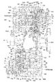
図2はエンジン17の内部構造を右側方から見た図であり、図3は、図2の前バンク110Aの内部構造を拡大して示す図である。
図2において、エンジン17の前バンク110A及び後バンク110Bは略同一の構造である。図2中、前バンク110Aはピストン周辺を示し、後バンク110Bはカムチェーン周辺を示している。また、図2において、符号121は中間シャフト(後側バランサシャフト)を示し、符号123はメインシャフトを示し、符号125はカウンタシャフトを示している。クランクシャフト105を含むこれらシャフト121,123,125は、車体前後方向及び上下方向にずらして互いに平行に配置され、これらシャフトを支持するクランクケース110C内には、クランクシャフト105の回転を、中間シャフト121、メインシャフト123及びカウンタシャフト125の順に伝達する歯車伝達機構が構成されている。
2 is a view of the internal structure of the
In FIG. 2, the
図2に示すように、エンジン17のクランクケース110C上面には、前側シリンダブロック131A及び後側シリンダブロック131Bが車体前後に所定の挟み角度をなすように配置され、これらシリンダブロック131A,131Bの上面に前側のシリンダヘッド132A、後側のシリンダヘッド132Bが各々結合され、さらに各シリンダヘッド132A,132Bの上面にはヘッドカバー133A,133Bが各々装着されて前バンク110A及び後バンク110Bが構成される。
As shown in FIG. 2, the
各シリンダブロック131A,131Bには、シリンダボア135が各々形成され、各シリンダボア135にはそれぞれピストン136が摺動自在に挿入され、各ピストン136は、コンロッド137を介してクランクシャフト105に連結される。
各シリンダヘッド132A,132Bの下面には、ピストン136上方に形成される燃焼室の天面を構成する燃焼凹部141が形成され、各燃焼凹部141には、点火プラグ142がその先端を臨ませて配置される。この点火プラグ142は、シリンダ軸線Cと略同軸に設けられる。
Each
Combustion recesses 141 constituting the top surface of the combustion chamber formed above the
エンジン17は、各燃焼凹部141に設けられたインジェクタ143から燃焼室に直接燃料を噴射する筒内噴射式エンジンである。各インジェクタ143は、各シリンダヘッド132A,132BのVバンク内側側面から挿入され、その先端を各燃焼凹部141に臨ませて配置される。インジェクタ143は、シリンダ軸線Cに対して寝かせた状態で取り付けられる。
ヘッドカバー133Aの上部には、燃料ポンプ144が設けられ、燃料ポンプ144から燃料配管144Aを介して各インジェクタ143に燃料が供給される。
The
A
各シリンダヘッド132A,132Bには、一対の開口部145Aによって各燃焼凹部141に連通する吸気ポート145と、一対の開口部146Aによって各燃焼凹部141に連通する排気ポート146とが形成されている。吸気ポート145は、シリンダ軸線Cとインジェクタ143との間に配置される。
各吸気ポート145は、図2及び図3に示すように、シリンダヘッド132A,132Bと一体に設けた下部吸気ポート145Bと、シリンダヘッド132A,132Bと別体に設けた上部吸気ポート145Cとを備えている。上部吸気ポート145Cは、下部吸気ポート145Bに対し、よりヘッドカバー133A,133Bに接近する方向に角度を変えて取り付けられている。
Each
2 and 3, each
各吸気ポート145は吸気チャンバ43で合流しており、この吸気チャンバ43はスロットルボディ42に連結される。スロットルボディ42には、スロットルバルブの断面積をアクチュエータの駆動により変化させるTBW(スロットル・バイ・ワイヤ)が採用されている。シリンダヘッド132Aの排気ポート146は、排気管18A(図1参照)に連結されており、シリンダヘッド132Bの排気ポート146は、排気管18B(図1参照)に連結されている。
The
シリンダヘッド132A,132Bには、吸気ポート145の開口部145Aを開閉する一対の吸気弁147(バルブ)と、排気ポート146の開口部146Aを開閉する一対の排気弁148(バルブ)とが配置される。吸気弁147及び排気弁148は、弁ばね149,149で各ポートを閉じる方向に各々付勢されている。各弁体147,148は、機関弁の開閉のタイミングやリフト量等のバルブ作動特性を変更可能な動弁装置50(可変動弁装置)によって駆動される。動弁装置50は、シリンダヘッド132A,132Bに回転可能に支持され、クランクシャフト105の回転に連動して回転する吸気側と排気側のカムシャフト151,152を備える。ここで、カムシャフト151,152は、図2及び図4中の反時計回転方向にそれぞれ回転する。
The
カムシャフト151には、吸気カム153が一体に形成されている。吸気カム153は、円形のカム面を形成するベース円部153Aと、ベース円部153Aから外周側に突出したカム面を形成するカム山部153Bとを備えている。また、カムシャフト152には、排気カム154が一体に形成されている。排気カム154は、円形のカム面を形成するベース円部154Aと、ベース円部154Aから外周側に突出して山形のカム面を形成するカム山部154Bとを備えている。
An
図2に示すように、シリンダヘッド132A,132Bの幅方向の一端側には、中間軸158が回転可能に支持され、この中間軸158に中間スプロケット159,160が固定される。カムシャフト151の一端側には被動スプロケット161が固定され、カムシャフト152の一端側には被動スプロケット162が固定され、クランクシャフト105の両端側には駆動スプロケット163が固定される。これらスプロケット159,163間には第1カムチェーン164が巻回され、スプロケット160〜162間には第2カムチェーン165が巻回される。これらスプロケット159〜163及びカムチェーン164,165は、各バンク110A,110Bの一端側に形成されたカムチェーン室166に収容される。
As shown in FIG. 2, the
駆動スプロケット163から被動スプロケット161,162への減速比は2に設定され、クランクシャフト105が回転すると、クランクシャフト105と一体に駆動スプロケット163が回転し、カムチェーン164,165を介して被動スプロケット161,162がクランクシャフト105の半分の回転速度で回転して、被動スプロケット161,162と一体に回転するカムシャフト151,152のカムプロフィールに従って吸気弁147及び排気弁148が吸気ポート145及び排気ポート146を各々開閉させる。
The reduction ratio from the
クランクシャフト105の左端部には図示しない発電機が設けられ、クランクシャフト105の右端部には、上記右側の駆動スプロケット163の内側(車体左側)に駆動歯車(以下、クランク側駆動歯車という)175が固定される。このクランク側駆動歯車175は、中間シャフト121に設けられた被動歯車(以下、中間側被動歯車という)177と噛み合い、クランクシャフト105の回転を等速で中間シャフト121に伝達し、クランクシャフト105と同速かつ逆向きで中間シャフト121を回転させる。
A generator (not shown) is provided at the left end portion of the
中間シャフト121は、クランクシャフト105の後側下方かつメインシャフト123の前側下方に回転可能に支持されている。
この中間シャフト121の右端部には、オイルポンプ用駆動スプロケット181と、上記中間側被動歯車177と、この被動歯車177より小径の駆動歯車(以下、中間側駆動歯車という)182とが順に取り付けられている。
オイルポンプ用駆動スプロケット181は、中間シャフト121の後側であって、メインシャフト123下方に配置されたオイルポンプ184の駆動軸185に固定された被動スプロケット186に伝動チェーン187を介して該中間シャフト121の回転力を伝達し、オイルポンプ184を駆動させる。
The
An oil
The oil
また、中間側駆動歯車182は、メインシャフト123に相対回転自在に設けられた被動歯車(以下、メイン側被動歯車という)191に噛み合い、中間シャフト121の回転を減速してクラッチ機構(不図示)を介してメインシャフト123に伝達する。すなわち、中間側駆動歯車182及びメイン側被動歯車191の減速比によって、クランクシャフト105からメインシャフト123までの減速比、つまり、エンジン17の1次減速比が設定される。
Further, the
メインシャフト123は、クランクシャフト105の後側上方に回転可能に支持され、メインシャフト123の略後方には、カウンタシャフト125が回転可能に支持される。メインシャフト123とカウンタシャフト125には、図示しない変速歯車群が跨って配置され、これらによって変速装置が構成される。
カウンタシャフト125の左端部は、車体の前後方向に延びるドライブシャフト(不図示)に連結される。これによって、カウンタシャフト125の回転がドライブシャフトに伝達される。
The main shaft 123 is rotatably supported on the rear upper side of the
The left end portion of the
図4は、動弁装置50を示す一部破断側面図であり、図5は、前バンク110Aの動弁装置50を後部側から見た縦断面図である。
動弁装置50は、図3に示すように、シリンダ軸線Cを中心として吸気側と排気側とに独立して略対称に設けられている。また、前バンク110A及び後バンク110Bの動弁装置50は略同一構造であるため、本実施の形態では、前バンク110Aの吸気側の動弁装置50について説明する。
FIG. 4 is a partially cutaway side view showing the
As shown in FIG. 3, the
動弁装置50は、図4及び図5に示すように、カムシャフト151(排気側ではカムシャフト152)と、カムシャフト151と一体回転する吸気カム153(排気側では排気カム154)と、吸気弁147(排気側では排気弁148)を開閉するロッカアーム51と、カムシャフト151に相対回転可能に支持され、ロッカアーム51を介して吸気弁147を開閉する動弁カム52と、カムシャフト151の周りを揺動自在なホルダー部材53と、ホルダー部材53に揺動可能に支持され、吸気カム153の弁駆動力を動弁カム52に伝達し、動弁カム52を揺動させるリンク機構56と、ホルダー部材53を回転させる駆動機構60とを備えている。また、リンク機構56は、ホルダー部材53に連結されるサブロッカアーム54と、サブロッカアーム54と動弁カム52とを揺動可能に連結するコネクトリンク55とを備えている。
4 and 5, the
ロッカアーム51は幅広に形成されており、1つのロッカアーム51によって一対の吸気弁147を開閉する。ロッカアーム51は、一端部において、シリンダヘッド132Aに固定されるロッカアームピボット51Aに揺動可能に支持される。ロッカアーム51の他端部には、各吸気弁147の上端部に当接するねじ式の調整部51Bが設けられ、中央部には、動弁カム52に接触するローラ51Cが回転可能に支持されている。
The
図5に示すように、カムシャフト151は、一端側に被動スプロケット161(図2参照)が固定されるスプロケット固定部151Aを有し、スプロケット固定部151Aの側から順に、カムシャフト151の外周に突出し断面円形形状を有する位置決め部151B、吸気カム153、動弁カム52を揺動可能に支持する動弁カム支持部151C、及び、動弁カム支持部151Cよりも小径に形成されたカラー嵌合部151Dが設けられている。カラー嵌合部151Dには、カムシャフト151のベアリングとして機能するカムシャフトカラー155が嵌合され、カムシャフトカラー155はカムシャフト151の他端側に締めこまれた固定ボルト156によって動弁カム52の側に押し付けられている。
As shown in FIG. 5, the
カムシャフト151は、その両端がそれぞれカムシャフト支持部201,202によって回転自在に支持されている。詳細には、カムシャフト支持部201,202は、シリンダヘッド132Aの上部に形成された断面半円状のヘッド側支持部201A,202Aに、断面半円状の支持部を有するキャップ201B,202Bをそれぞれ固定して構成されている。位置決め部151Bの側に設けられたカムシャフト支持部201には、位置決め部151Bの形状に合わせて形成された溝201Cが形成され、位置決め部151Bの位置が溝201Cに規制されることによって、カムシャフト151は軸方向に位置決めされている。
また、カムシャフト支持部201,202における吸気カム153の側の面には、ホルダー部材53を支持するホルダ支持部201D,202Dがそれぞれ設けられている。
Both ends of the
Further,
動弁カム52は、カムシャフト151の中間部に設けられた動弁カム支持部151Cに枢支されている。動弁カム52には、図4に示すように、吸気弁147を閉弁状態に維持するベース円部52Aと、吸気弁147を押し下げて開弁させるカム山部52Bとが形成され、カム山部52Bには貫通孔52Cが形成されている。貫通孔52Cには、カム山部52Bがロッカアーム51のローラ51Cから離れる方向、すなわち、吸気弁147を閉弁する方向に動弁カム52を付勢する動弁カムリターンスプリング57(図5参照)の一端57Aが取り付けられる。動弁カムリターンスプリング57は、図5に示すように、ねじりコイルばねであり、コイル部57Bがカムシャフト151に巻き掛けられ、その他端57Cは、ホルダー部材53の端部に形成された溝部69に取り付けられる。コイル部57Bは溝部69を越えて軸方向に長く形成され、他端57Cは、コイル部57Bに重なるようにして一端57Aの側に巻かれている。このため、動弁カムリターンスプリング57の巻き数を確保しつつ、動弁カムリターンスプリング57を軸方向にコンパクトに配置できる。
The
ホルダー部材53は、吸気カム153及び動弁カム52を挟んでカムシャフト151の軸方向に所定の間隔を空けて配置される第1,第2プレート53A,53Bと、第1,第2プレート53A,53Bをカムシャフト151の軸方向に連結するサブロッカアームホルダ59とを備えている。第1プレート53Aはカムシャフト151の被動スプロケット161が固定される一端側に配置され、第2プレート53Bはカムシャフト151の他端側に配置される。
The
また、サブロッカアームホルダ59は、カムシャフト151と平行な軸部59A、59Cと、軸部59Aと軸部59Cとを一体に結合する結合部45とを備えて構成されている。また、結合部45には円筒状の収容部74が形成され、収容部74には、サブロッカアーム54を吸気カム153側に付勢するサブロッカアームリターンスプリング58(以下、リターンスプリングという)が収容されている。
軸部59Aの第1プレート53A側の端には、サブロッカアーム54の一端が連結されるサブロッカアーム支持部59B(支点)が形成されている。サブロッカアーム支持部59Bは、軸部59Aよりも小径に形成された軸である。
これら第1,第2プレート53A,53B及びサブロッカアームホルダ59は、第1プレート53Aの外面側から第1プレート53Aとサブロッカアームホルダ59とを締結する一対のボルト53Dと、第2プレート53Bの外面側から第2プレート53Bとサブロッカアームホルダ59とを締結する一対のボルト53Eとによって固定される。これらのボルト53D,53Eが螺号される雌ネジ部79は、軸部59A,59Cにそれぞれ形成されている。
また、第2プレート53Bには、駆動機構60と連結されるボルト孔53Cが形成されている。
The sub
A sub rocker
The first and
Further, the
第1,第2プレート53A,53Bは、図5に示すように、カムシャフト151が貫通するシャフト孔157A,158Aをそれぞれ有し、これらシャフト孔157A,158Aの周縁部は、カムシャフト支持部201,202のホルダ支持部201D,202Dに向けて突出した円環状の環状凸部157B,158Bとなっている。ホルダー部材53は、環状凸部157B,158Bがホルダ支持部201D,202Dにそれぞれ嵌合されることで支持され、カムシャフト151を中心に回動可能となっている。また、環状凸部157B,158Bは、カムシャフト151と同軸に組付けされる。
また、キャップ201Bの端とボルト53Dとの間、及び、キャップ202Bとボルト53Eとの間には、軸方向に隙間Sが形成されている。この隙間Sは、キャップ201B,202Bをヘッド側支持部201A,202Aに上方からそれぞれ組み付ける際に、キャップ201B,202Bがボルト53D,53Eに当たらない大きさに設定されている。このため、組み付け作業時にボルト53D,53Eが邪魔にならず、組立て性が良い。
As shown in FIG. 5, the first and
A gap S is formed in the axial direction between the end of the
サブロッカアーム54は、第1,第2プレート53A,53B間に吸気カム153及び動弁カム52と共に配置されており、その一端部においてサブロッカアームホルダ59のサブロッカアーム支持部59Bに支持され、サブロッカアーム支持部59Bを中心として揺動するようになっている。サブロッカアーム54の中央部には、吸気カム153に接触してベース円部153A及びカム山部153Bを押圧するローラ54Aが回転可能に支持されている。サブロッカアーム54の他端部には、コネクトリンク55を揺動可能に支持するピン55Aを介してコネクトリンク55の一端が連結され、コネクトリンク55の他端には、動弁カム52を揺動可能に支持するピン55Bを介して動弁カム52が連結される。
また、サブロッカアーム54は、リターンスプリング58により付勢されており、サブロッカアーム54のローラ54Aは常に吸気カム153に押し付けられている。
The
Further, the
サブロッカアーム54は、サブロッカアーム支持部59Bに連結されてカムシャフト151に直交するように延びるホルダ連結部54Bと、ホルダ連結部54Bからカムシャフト151の外径に沿うように下方に湾曲する偏心部54Cと、コネクトリンク55を介して動弁カム52に連結されるリンク部54Dとを有している。
偏心部54Cは、第1プレート53Aの側から第2プレート53Bの側に吸気カム153を避けるようにカムシャフト151の軸方向に偏心し、この偏心部54Cの側面には、カムシャフト151の軸方向に張り出た板状の段部76が形成されている。段部76はサブロッカアーム54の下縁部に沿って湾曲して設けられている。リターンスプリング58の下端は、ばね座金77(図4参照)を介して段部76によって受けられている。リターンスプリング58の上端は、収容部74に係合するサークリップ78によって受けられている。
リンク部54Dは偏心部54Cの端に連続して設けられ、コネクトリンク55を介して動弁カム52に連結されている。このように、サブロッカアーム54は偏心部54Cが偏心することで、カムシャフト151上の軸方向に異なる位置に設けられた吸気カム153と動弁カム52とを連結している。
The
The
The
次に、動弁装置50の動作を説明する。
上記のように構成された動弁装置50において、図4を参照し、カムシャフト151が図中の反時計方向に回転されると、カムシャフト151と一体に回転する吸気カム153のカム山部153Bにより、サブロッカアーム54がローラ54Aを介して押し上げられて軸部59Aを中心として揺動し、これに伴い、コネクトリンク55を介して動弁カム52がカムシャフト151を中心として図4中の時計回りに回転する。そして、動弁カム52の回転によりカム山部52Bがローラ51Cを介してロッカアーム51を押圧し、ロッカアーム51を介して吸気弁147が押し下げられ、吸気弁147が開弁される。
また、カムシャフト151がさらに回転されて吸気カム153のベース円部153Aがローラ54Aに当接する状態では、サブロッカアーム54がリターンスプリング58により押し下げられると共に、動弁カム52が動弁カムリターンスプリング57より図4中の反時計回りに回転させられてベース円部52Aがローラ51Cに当接する。これにより、吸気弁147は弁ばね149(図2参照)により押し上げられて閉弁される。
Next, the operation of the
In the
When the
この動弁装置50では、図4に示すように、ホルダー部材53に駆動機構連結部材63を接続している。駆動機構連結部材63は駆動機構60(図6参照)に接続され、ホルダー部材53は駆動機構60の駆動によって、矢印A方向及び矢印B方向に揺動させられる。
ホルダー部材53を矢印A方向に揺動させると、ホルダー部材53と共にサブロッカアーム支持部59Bの位置が変化し、リンク機構56がカムシャフト151の軸心を中心に時計回り方向に揺動し、ローラ54Aは時計回り方向に揺動し、動弁カム52は時計回り方向に揺動する。一方、矢印B方向に移動すると、ホルダー部材53と共にリンク機構56がカムシャフト151の軸心を中心に反時計回り方向に揺動し、ローラ54Aは反時計回り方向に揺動し、動弁カム52は反時計回り方向に揺動する。このように、動弁装置50では、ローラ54Aの位置及び動弁カム52の揺動の初期位置を変化させることで、吸気弁147及び排気弁148のバルブ作動特性、すなわち、吸気弁147及び排気弁148の開閉時期、開閉期間、及び、リフト量を制御可能に構成されている。
ここで、動弁カム52の揺動の初期位置とは、ローラ54Aが吸気カム153のベース円部153Aに当接しており、サブロッカアーム54がカム山部153Bによって押し上げられていない状態における動弁カム52の揺動位置を指している。また、吸気弁147及び排気弁148の開閉時期とは、カムシャフト151,152の回転に対する吸気弁147及び排気弁148の開閉のタイミング、すなわち、吸気弁147及び排気弁148の開閉の位相を指している。
In this
When the
Here, the initial position of the swing of the
例えば、吸気側のホルダー部材53を矢印A方向(図4中の時計回り方向)にさらに揺動させると、ローラ54A及び動弁カム52は時計回り方向に回転され、カム山部52Bはローラ51Cに近くなり、この状態でカムシャフト151が回転されると、カム山部153Bによるローラ54Aの押し上げの開始時期が早くなると共に、カム山部52Bがローラ51Cを押し下げる期間及び押し下げ量が大きくなる。これにより、吸気弁147の開弁時期が早められると共に、吸気弁147の開弁期間及びリフト量が大きくなる。
For example, when the
図6は、駆動機構60を側面側から見た縦断面図である。図7は、エンジン17を上方から見た横断面図である。なお、図7では、前後バンク110A,110Bは、エンジン17の上方からシリンダ軸線C(図2参照)に沿って見た図が示されている。また、図7に示すように、後バンク110Bは、前バンク110Aをシリンダボア135を中心にして180°回転させてクランクケース110Cの後部に配置されており、ここでは、後バンク110Bの詳細な説明は省略する。
FIG. 6 is a longitudinal sectional view of the
駆動機構60は、図6に示すように、駆動機構連結部材63を介してホルダー部材53に連結されている。駆動機構60は、カムシャフト151とカムシャフト152とに跨って配置された棒状のボールねじ61(被回転角検出対象軸、回転軸)と、吸気側及び排気側のそれぞれに設けられ、ボールねじ61上を軸方向に移動可能な2つのスライダー62と、ボールねじ61を回転させる電動アクチュエータ70(図7参照)と、駆動機構連結部材63とを有している。駆動機構連結部材63は、スライダー62とホルダー部材53との間に設けられている。
As shown in FIG. 6, the
ボールねじ61のカムシャフト152側の前端部にはギヤ64が固着され、ギヤ64には、電動アクチュエータ70が、シリンダヘッド132Aの上部側壁を内外に跨って設けられるギヤ輪列を介して連結されている。電動アクチュエータ70は、車両の電子制御ユニット(ECU)により制御され、このECUが電動アクチュエータ70を駆動することにより、ボールねじ61及び駆動機構連結部材63を介してホルダー部材53が揺動され、吸気弁147及び排気弁148の開閉の作動特性がエンジン17の運転状態に応じて制御される。
A
電動アクチュエータ70は、電動モータ71と、電動モータ71の駆動軸72と、駆動軸72から電動モータ71の駆動力が伝達される中間軸73とを備えている。電動モータ71は、その駆動軸72がボールねじ61と略平行な状態で、シリンダヘッド132Aの上部における車幅方向の外側側面139に固定されている。電動アクチュエータ70は外側側面139の前部に配置されており、エアクリーナ41は、電動アクチュエータ70の後部に連続するように車両前後方向に延在している。
駆動軸72には、駆動歯車部72Aが形成されており、中間軸73には、駆動歯車部72Aと噛み合う第1中間ギヤ73Aと、ボールねじ61に設けられたギヤ64と噛み合う第2中間ギヤ73Bとが固定されている。
The
The
図7に示すように、エンジン17は、前バンク110A及び後バンク110Bが、各シリンダボア135に対してカムチェーン室166側にオフセットされて構成されている。すなわち、前バンク110A及び後バンク110Bは、各シリンダボア135を中心とした場合、カムチェーン室166側の側壁が、電動アクチュエータ70が配置された側の外側側面139よりも車幅方向に膨出している。本実施の形態では、電動アクチュエータ70が前バンク110A及び後バンク110Bの反オフセット側Qに配置されているため、電動アクチュエータ70を含めた前バンク110A及び後バンク110Bの車幅方向の大きさが、車幅方向の片側に偏って大きくなることを防止でき、電動アクチュエータ70をコンパクトに配置できる。
また、電動アクチュエータ70がシリンダヘッド132A,132Bの外側に設けられており、シリンダヘッド132A,132B内にスペースを確保できるため、シリンダヘッド132A,132B内にボールねじ61やスライダー62等を効率良く配置できる。
As shown in FIG. 7, the
In addition, since the
ボールねじ61は、カムシャフト151,152と直交し、これらカムシャフト151,152の他端側、すなわち、被動スプロケット161,162が固定される側と反対側に配置されている。このように、ボールねじ61は、エンジン17の上下方向に延出するのではなく、カムシャフト151とカムシャフト152とに跨って寝かせて配置されるので、エンジン17の高さを低く抑えることが可能になる。
ボールねじ61は、その両端がそれぞれボールねじ支持部203によって回転自在に支持されている。ボールねじ支持部203は、図5に示すように、カムシャフト支持部202の上部に形成されたカムシャフト側支持部203Aに、断面半円状の支持部を有するキャップ203Bをそれぞれ固定して構成されている。
図6に示すように、ボールねじ61の外周面には、吸気側及び排気側に螺旋状のねじ山61A,61Bと、螺旋状の軸ねじ溝61C,61Dとが形成されている。これらねじ山61A,61B及び軸ねじ溝61C,61Dは、ねじの巻き方向が吸気側と排気側とで互いに逆方向となるように設定されている。
The ball screw 61 is orthogonal to the
Both ends of the
As shown in FIG. 6, on the outer peripheral surface of the
スライダー62はブロック状に形成され、ボールねじ61が貫通する貫通孔62Aを有している。貫通孔62Aの内周面には、ねじ山61A,61Bに対応する螺旋状のナットねじ山62Bと、軸ねじ溝61C,Dに対応する螺旋状のナットねじ溝62Cが形成されている。各ナットねじ溝62Cと軸ねじ溝61C,61Dとの間には、転動可能な複数のボール65が配置される。スライダー62は、ボールねじ61が回転されることにより、ボール65を介してボールねじ61上を軸方向に移動する。
The
駆動機構連結部材63は、スライダー62に連結されるアーム部材86と、アーム部材86をホルダー部材53の第2プレート53Bに連結する連結部材87とを有している。連結部材87は、第2プレート53Bとアーム部材86との間を連結するボルト及びナットにより構成されている。アーム部材86は、側面視で略L字状に形成されており、一端86Aが連結部材87を介して第2プレート53Bに固定され、他端86Bがスライダー62に揺動可能に連結されている。詳細には、アーム部材86の他端86Bはスライダー62の両側面に延び、スライダー62を両側面から挟むようにして連結されている。
The drive
スライダー62と一体にアーム部材86がボールねじ61の軸方向に移動させられると、アーム部材86は他端86Bを中心に揺動しつつホルダー部材53を引っ張り、一端86Aに連結されたホルダー部材53を揺動させる。
また、スライダー62及びアーム部材86は、カムシャフト151とカムシャフト152とにおいて、同一の部品がボールねじ61の軸方向中間部を中心に対称に配置されている。ボールねじ61が回転されると、各スライダー62は互いに反対方向に移動し、吸気側及び排気側のホルダー部材53をそれぞれ揺動させる。
When the
Further, the
図6に示すように、ボールねじ61におけるカムシャフト151側の端に近接するシリンダヘッド132Aの壁部には、ボールねじ61の回転量である回転角度を検出するセンサ80(回転角センサ)が設けられている。ボールねじ61は、センサ80によって回転角を検出される被回転角検出対象軸である。上記ECUは、センサ80によって検出されたボールねじ61の回転角に基づいてホルダー部材53の揺動量を算出し、この算出値をバルブ作動特性の制御に利用する。
センサ80は、シリンダヘッド132Aに設けられたセンサ支持壁88によって支持されている。
As shown in FIG. 6, a sensor 80 (rotation angle sensor) that detects a rotation angle that is a rotation amount of the
The
図8は、センサ支持壁88の正面図である。
図6、図7及び図8に示すように、センサ支持壁88は、側面視で略L字状に形成されたプレートであり、シリンダヘッド132Aの上下方向に延びる壁部89と、壁部89の下端に設けられシリンダヘッド132Aの側壁の上面132A1に固定される基部90とを有している。
壁部89の上部には、Vバンク空間Kの側に突出する厚肉部89Aが設けられ、厚肉部89Aには、センサ80を支持するセンサ支持孔89Bが形成されている。センサ支持孔89Bは、厚肉部89Aを貫通する円形の開口である。また、厚肉部89Aにおいてセンサ支持孔89Bの下方には、雌ねじ部89Cが形成されている。壁部89の外縁部89Dは、上部に向かって先細りに形成された左右の側縁部と、両側縁部の上部に連続した曲面状の上縁部で構成されている。外縁部89Dは、ヘッドカバー133Aとシリンダヘッド132Aの上面132A1との間をシールするガスケット67の受け面となっている。
FIG. 8 is a front view of the
As shown in FIGS. 6, 7 and 8, the
A
基部90には、上面132A1の側に形成された穴部(不図示)に嵌合される一対の位置決めピン90Aが設けられており、センサ支持壁88は、位置決めピン90Aを貫通して上面132A1に締結される一対のボルト66によってシリンダヘッド132Aの上部に一体的に固定される。
センサ支持壁88は、Vバンク空間Kを区画するシリンダヘッド132A,132Bの内側側壁140(シリンダヘッド側壁)に連続して設けられており、シリンダヘッド132A,132Bの上部の側壁の一部を構成している。内側側壁140は、ボールねじ61に直交するシリンダヘッド132Aの側壁である。また、センサ支持壁88は、内側側壁140において電動アクチュエータ70側の端に配置され、ボールねじ61の軸方向の延長線上に位置している。
The
The
図6に示すように、センサ80は、円筒状の本体部80Aと、本体部80Aの一端側に設けられ、検出対象の回転が入力される入力部80Bと、他端側において本体部80Aから突出したステー部80Cとを有している。入力部80Bは検出対象に接続されて検出対象と一体に回転され、この際の回転角を検出することで検出対象の回転角を得る。入力部80Bは本体部80Aの軸心に設けられており、この軸心を中心に回転する。ここで、センサ80は、ポテンショメータである。詳細には、センサ80は、検出可能な角度範囲が複数回転ではなく、1回転(360°)以内のポテンショメータであり、構造が比較的簡単であるため、安価に入手できる。
As shown in FIG. 6, the
センサ80は、センサ支持壁88のセンサ支持孔89B内に支持され、入力部80Bをシリンダヘッド132Aの内部に向けた状態で配置されている。本体部80Aとセンサ支持孔89Bとの間にはゴム製のOリング80Dが介装されている。また、センサ80は、ステー部80Cを貫通して雌ねじ部89Cに締結されるセンサ固定ボルト80Eによってセンサ支持壁88に固定されている。
The
センサ80は、センサ支持壁88に支持され、その後部がVバンク空間K内に露出して配置されている。図7に示すように、Vバンク空間K内には、吸気チャンバ43とスロットルボディ42との接続部42Aが設けられており、センサ80は接続部42Aと前バンク110Aの内側側壁140との間の空間に配置されている。また、後バンク110Bのセンサ80は、燃料配管144Aと各インジェクタ143とを接続する燃料パイプ180と、後バンク110Bの内側側壁140との間の空間に配置されている。
このように、センサ80をVバンク空間K内において、内側側壁140と接続部42Aとの間、及び、内側側壁140と燃料パイプ180との間に配置したため、センサ80を、吸気チャンバ43、スロットルボディ42及び燃料パイプ180等の他の部品の配置の邪魔にならないようにコンパクトに配置できる。また、センサ80の前後がエンジン17で囲われているため、センサ80に対して飛び石等が当たることを防止できる。
The
As described above, since the
図9は、図6におけるセンサ80の周辺部の拡大図である。
ボールねじ61とセンサ80との間には、回転伝達部91が設けられており、この回転伝達部91によってボールねじ61の回転がセンサ80に伝達される。
回転伝達部91は、ボールねじ61におけるギヤ64とは反対側の一端に形成された出力軸部92と、この出力軸部92の下方に出力軸部92と平行に配置されるギヤ支持軸93と、ギヤ支持軸93に軸支されて出力軸部92と噛み合うリダクションギヤ94と、リダクションギヤ94に一体に固定されると共にセンサ80に取り付けられるセンサ連結具95(取り付け支持部)とを有している。
FIG. 9 is an enlarged view of the periphery of the
A
The
出力軸部92は、リダクションギヤ94と噛み合う駆動ギヤ92Aを有し、この駆動ギヤ92Aは、ボールねじ61の端部の外周面をギヤ形状に成形したものである。リダクションギヤ94の歯数は駆動ギヤ92Aの歯数よりも多く設けられており、ボールねじ61の回転は、リダクションギヤ94によって減速される。詳細には、駆動ギヤ92Aとリダクションギヤ94との間の減速比は、ボールねじ61の最大の回転角度、すなわち、ホルダー部材53の揺動可能範囲に対応して設定されており、ボールねじ61が複数回に亘って回転し、ホルダー部材53が揺動可能範囲の全範囲に亘って揺動した場合においても、リダクションギヤ94の回転角が1回転以下となるように設定されている。
The
ギヤ支持軸93は、ボールねじ支持部203に締め込まれる支持ボルト96と、支持ボルト96の軸部96Aに嵌合されてボールねじ支持部203に固定されるカラー97とを有している。支持ボルト96は、軸部96A及び六角形の頭部96Bを有する六角ボルトである。支持ボルト96は、ボールねじ支持部203においてセンサ支持壁88に対向する側の壁部である支持壁210に固定されており、ボールねじ61の直下でボールねじ61と平行に設けられている。支持壁210には、支持ボルト96が螺合する雌ねじ部210Aと、支持壁210の表面側に雌ねじ部210Aよりも大径で高精度に形成された位置決め穴210Bとが形成されている。支持壁210は出力軸部92の先端よりもシリンダヘッド132Aの内側に位置すると共に、センサ支持壁88に対して略平行に設けられており、支持壁210とセンサ支持壁88との間には、回転伝達部91を配置可能な空間Mが形成されている。
The
図10は、カラー97の断面図である。
カラー97は、円筒状のカラー軸部97Aと、カラー軸部97Aの一端側にカラー軸部97Aよりも小径で高精度に形成された位置決め部97Bと、他端側にカラー軸部97Aよりも大径に形成された鍔部97Cと、支持ボルト96の軸部96Aに嵌合する内径部97Dとを有している。
カラー97は、位置決め部97Bが位置決め穴210Bに係合することで支持壁210に位置決めされ、支持ボルト96の締結力により鍔部97Cの端面に当接する頭部96Bによって支持壁210に固定される。支持ボルト96は、頭部96Bがセンサ80の入力部80Bに対向するように配置され、支持ボルト96の軸心とセンサ80の軸心とは略一致している。
FIG. 10 is a cross-sectional view of the
The
The
リダクションギヤ94は、リダクションギヤ94の中央部に設けられるベアリング98を介してカラー97に支持されている。
ベアリング98は、ボールベアリングであり、外径側のアウタレース98Aと、内径側のインナレース98Bと、アウタレース98Aとインナレース98Bとの間に設けられる複数のボール98Cとを備えて構成されている。
リダクションギヤ94は円板状に形成され、中央部には、円形に開口した圧入孔94Aが形成されている。ベアリング98は、アウタレース98Aが圧入孔94Aに圧入されることでリダクションギヤ94に一体に設けられている。
The
The
The
ベアリング98は、インナレース98Bがカラー軸部97Aの外周面に嵌合されてカラー97に取り付けられ、支持ボルト96の締結力を受けた鍔部97Cによって支持壁210に押し付けられて固定される。
このように、リダクションギヤ94は、ボールねじ61の下方の支持壁210に締結される1本の支持ボルト96によって片持ち支持されている。このため、リダクションギヤ94を設けるために支持ボルト96の軸方向に大きなスペースが必要なく、リダクションギヤ94をコンパクトに配置できる。また、カラー97が、高精度に形成された位置決め部97B及び位置決め穴210Bによって位置決め及び支持された状態で、支持ボルト96の締結力によって固定されているため、片持ち支持であってもカラー97及びベアリング98を確実に固定でき、リダクションギヤ94を確実に支持できる。
The
Thus, the
図11は、センサ連結具95を示す図であり、図11(a)は平面図、図11(b)は図11(a)のXI−XI断面図である。なお、図11(a)では、センサ連結具95と共にリダクションギヤ94を2点鎖線で示している。
図9及び図11に示すように、センサ連結具95は、略円板状の板材の中央部を凸状に膨出させるようにして形成されており、円環状に形成されてリダクションギヤ94の外側面94Bに当接するベース部99と、中央部で凸状に膨出した膨出部100とを有している。膨出部100の内側には、収容空間Fが形成されている。
FIG. 11 is a view showing the
As shown in FIGS. 9 and 11, the
ベース部99には、ベース部99の一部が径方向に突出した取付部99Aが3箇所に形成されており、各取付部99Aには、取付部99Aを貫通する孔99Bが形成されている。各取付部99Aは、ベース部99の外周を3等分するように互いに略等間隔をあけて配置されている。
膨出部100は、膨出部100の円盤状の端面を形成して頭部96Bに対向する頂部100Aと、頂部100Aの外縁とベース部99とを繋ぐ筒状の外壁部100Bとを有している。外壁部100Bには、外壁部100Bを貫通して収容空間Fに連通する連通孔100Cが複数形成されている。
センサ連結具95の頂部100Aには、頂部100Aの面に垂直なセンサ接続軸101が立設されており、このセンサ接続軸101には、センサ接続軸101の円形断面の一部を軸方向に亘って切り欠いたキー部101Aが形成されている。
The
The bulging
A
図11に示すように、リダクションギヤ94には、センサ連結具95の各孔99Bに対応した位置にねじ孔部94Cがそれぞれ形成されている。センサ連結具95は、膨出部100の側から孔99Bに挿通されてねじ孔部94Cに締結される固定ボルト102によって、リダクションギヤ94に一体に固定される。
センサ連結具95は、支持ボルト96の頭部96Bを覆うように跨いでリダクションギヤ94の外側面94Bに固定され、膨出部100と外側面94Bとの間の収容空間Fには、支持ボルト96の頭部96B及びカラー97の鍔部97Cが収容されている。
As shown in FIG. 11, screw holes 94 </ b> C are formed in the
The
センサ連結具95は、センサ接続軸101の軸心が、支持ボルト96の軸心、すなわち、リダクションギヤ94の回転中心と同軸となるように固定されている。センサ接続軸101は、リダクションギヤ94と一体にリダクションギヤ94と同一の回転数で回転する。
センサ連結具95のセンサ接続軸101は、センサ支持壁88に支持されたセンサ80の入力部80Bに挿入されて入力部80Bに接続されており、入力部80Bはセンサ接続軸101と一体に回転する。入力部80Bはキー部101Aに対応した形状に形成されており、センサ接続軸101はキー部101Aによって入力部80Bに確実に接続される。
The
The
ここで、センサ80及びリダクションギヤ94の動作について説明する。
ECUの指示によって電動アクチュエータ70が駆動されてボールねじ61が回転されると、出力軸部92がボールねじ61と一体に回転し、出力軸部92の回転はリダクションギヤ94に伝達される。ここで、出力軸部92の回転はリダクションギヤ94で減速される。次いで、リダクションギヤ94の回転に伴って、センサ連結具95がリダクションギヤ94と一体に回転され、センサ80の入力部80Bは、センサ接続軸101によってリダクションギヤ94と同一の回転数で回転させられる。そして、ECUは、センサ80で検出したリダクションギヤ94の回転数に基づいて、ボールねじ61の回転数を算出する。
Here, operations of the
When the
本実施の形態では、リダクションギヤ94を、支持ボルト96の軸方向の一端側で片持ち支持し、支持ボルト96の他端側に設けられたセンサ連結具95のセンサ接続軸101をセンサ80の入力部80Bに接続したため、リダクションギヤ94の支持及びリダクションギヤ94の回転のセンサ80へ伝達のために大きなスペースが必要ない。このため、センサ80の取り付け構造をボールねじ61及びギヤ支持軸93の軸方向に小型化できる。
In the present embodiment, the
センサ80の取り付けは、センサ支持壁88のセンサ支持孔89Bにセンサ80を挿入して入力部80Bをセンサ連結具95に接続し、センサ固定ボルト80Eをセンサ支持壁88の雌ねじ部89Cに締結することで行うことができる。このため、シリンダヘッド132Aの外側からセンサ80のメンテナンスを行うことができ、メンテナンス性が良い。また、本体部80Aとセンサ支持孔89Bとの間にはOリング80Dが介装されており、組み付け誤差等によるセンサ接続軸101と入力部80Bとの間の同軸度のズレをOリング80Dの変形によって吸収できるため、センサ80とセンサ連結具95との間に歪みが生じることを防止して、フリクションを低減できる。
The
以上説明したように、本発明を適用した実施の形態によれば、ベアリング98のアウタレース98Aをリダクションギヤ94に圧入し、インナレース98Bを支持ボルト96によって支持壁210に固定すると共に、リダクションギヤ94の外側面94Bにセンサ連結具95を一体に固定し、センサ連結具95をセンサ80に接続したため、リダクションギヤ94の取り付けのためのベアリング98が一つで済む。これにより、リダクションギヤ94を取り付けるために大きなスペースが必要ないため、センサ80の取り付け構造をボールねじ61の軸方向に小型化できる。また、リダクションギヤ94を支持するためのベアリング98が一つで済むため、部品点数を削減できる。さらに、リダクションギヤ94に一体に固定したセンサ連結具95をセンサ80に接続したため、センサ80の取り付け構造を軸方向に小型化できる。
As described above, according to the embodiment to which the present invention is applied, the
また、安価なポテンショメータであるセンサ80を用いてボールねじ61の回転角を検出できる。
また、電動アクチュエータ70をボールねじ61と平行にシリンダヘッド132Aの外側側面139に設け、センサ80をボールねじ61と直交する内側側壁140に設けたため、電動アクチュエータ70及びセンサ80が他の部品の配置の邪魔にならないと共に、電動アクチュエータ70及びセンサ80をコンパクトに配置できる。
Further, the rotation angle of the
Further, since the
さらに、電動アクチュエータ70が、前バンク110A及び後バンク110Bの反オフセット側Qに配置されるため、電動アクチュエータ70をコンパクトに配置でき、エンジン17の車幅方向の大きさを小さく抑えることができる。
さらにまた、センサ80がVバンク空間Kの内側に配置されるため、センサ80を、吸気チャンバ43、スロットルボディ42及び燃料パイプ180等の他の部品の配置の邪魔にならないようにコンパクトに配置できる。
また、自動二輪車10の前後方向に配置されたVバンク空間Kの内側にセンサ80が配置され、センサ80がエンジン17によって囲われるため、飛び石等がセンサ80に当たることを防止できる。
Further, since the
Furthermore, since the
Further, since the
なお、上記実施の形態は本発明を適用した一態様を示すものであって、本発明は上記実施の形態に限定されない。
上記実施の形態では、エンジン17の動弁装置50は、吸気弁147及び排気弁148の開閉の位相及びリフト量を変化させるものとして説明したが、本発明はこれに限定されるものではない。動弁装置は、吸気弁147及び排気弁148の開閉の位相及び/またはリフト量を変化させるものであれば良く、開閉の位相のみ、または、リフト量のみを変化させるものであっても良い。また、その他の細部構成についても任意に変更可能であることは勿論である。
In addition, the said embodiment shows the one aspect | mode which applied this invention, Comprising: This invention is not limited to the said embodiment.
In the above embodiment, the
10 自動二輪車
17 エンジン(V型内燃機関)
50 動弁装置(可変動弁装置)
61 ボールねじ(被回転角検出対象軸、回転軸)
70 電動アクチュエータ(アクチュエータ)
80 センサ(回転角センサ)
92A 駆動ギヤ
94 リダクションギヤ
94B 外側面(側面)
95 センサ連結具(取り付け支持部)
96 支持ボルト(ボルト)
96B 頭部
98 ベアリング
98A アウタレース
98B インナレース
110A 前バンク(シリンダ)
110B 後バンク(シリンダ)
132A シリンダヘッド
140 内側側壁(シリンダヘッド側面)
147 吸気弁(バルブ)
148 排気弁(バルブ)
210 支持壁
K Vバンク空間(Vバンク)
Q 反オフセット側
10
50 Valve train (variable valve train)
61 Ball screw (Rotation angle detection target axis, rotation axis)
70 Electric actuator (actuator)
80 sensor (rotation angle sensor)
95 Sensor connector (mounting support)
96 Support Bolt (Bolt)
110B Rear bank (cylinder)
147 Intake valve
148 Exhaust valve
210 Support Wall K V Bank Space (V Bank)
Q Anti-offset side
Claims (6)
前記リダクションギヤの中央部にベアリングのアウタレースを圧入固定し、前記ベアリングのインナレースをボルトによって支持壁に固定すると共に、前記リダクションギヤの側面に前記ボルトの頭部を跨ぐ回転角センサの取り付け支持部を一体に固定したこと、
を特徴とする回転角センサ取り付け構造。 In the rotation angle sensor mounting structure for detecting the rotation of the rotation angle detection target shaft through the reduction gear,
The outer race of the bearing is press-fitted and fixed to the central portion of the reduction gear, the inner race of the bearing is fixed to a support wall with a bolt, and the mounting support portion of the rotation angle sensor that straddles the bolt head on the side of the reduction gear Fixed together,
A rotation angle sensor mounting structure characterized by
を特徴とする請求項1記載の回転角センサ取り付け構造。 The rotation angle sensor is a potentiometer;
The rotation angle sensor mounting structure according to claim 1.
シリンダヘッド側面に設けたアクチュエータにより前記アクチュエータと平行に設けた回転軸を駆動してバルブの位相及び/またはリフト量を変化させ、前記回転軸は前記被回転角検出対象軸とし、前記回転軸の端部に前記リダクションギヤの駆動ギヤを設け、前記回転角センサは前記回転軸と直交するシリンダヘッド側面に設けたことを特徴とする内燃機関の可変動弁装置。 While using the rotation angle sensor mounting structure according to claim 1 or 2,
A rotary shaft provided in parallel with the actuator is driven by an actuator provided on the side surface of the cylinder head to change the phase and / or lift amount of the valve. The rotary shaft is used as the rotation angle detection target axis, A variable valve operating apparatus for an internal combustion engine, wherein a driving gear of the reduction gear is provided at an end, and the rotation angle sensor is provided on a side surface of a cylinder head perpendicular to the rotation shaft.
を特徴とする請求項3記載の内燃機関の可変動弁装置。 The internal combustion engine is a V-type internal combustion engine in which cylinders are arranged in a V shape, and the actuator is arranged on the opposite offset side of the front and rear cylinders;
The variable valve operating apparatus for an internal combustion engine according to claim 3.
を特徴とする請求項3または4記載の内燃機関の可変動弁装置。 The rotation angle sensor is disposed inside the V bank;
The variable valve operating apparatus for an internal combustion engine according to claim 3 or 4, characterized by the above.
を特徴とする請求項5記載の内燃機関の可変動弁装置。 The internal combustion engine is an internal combustion engine of a motorcycle in which the V banks are arranged in a longitudinal direction of a vehicle body;
The variable valve operating apparatus for an internal combustion engine according to claim 5.
Priority Applications (2)
| Application Number | Priority Date | Filing Date | Title |
|---|---|---|---|
| JP2009295156A JP5149268B2 (en) | 2009-12-25 | 2009-12-25 | Rotation angle sensor mounting structure and variable valve operating apparatus for internal combustion engine using the same structure |
| US12/965,055 US8528389B2 (en) | 2009-12-25 | 2010-12-10 | Rotation angle sensing assembly including attaching structure, variable valve mechanism for internal combustion engine using the attaching structure, and vehicle incorporating the same |
Applications Claiming Priority (1)
| Application Number | Priority Date | Filing Date | Title |
|---|---|---|---|
| JP2009295156A JP5149268B2 (en) | 2009-12-25 | 2009-12-25 | Rotation angle sensor mounting structure and variable valve operating apparatus for internal combustion engine using the same structure |
Publications (2)
| Publication Number | Publication Date |
|---|---|
| JP2011132926A JP2011132926A (en) | 2011-07-07 |
| JP5149268B2 true JP5149268B2 (en) | 2013-02-20 |
Family
ID=44186717
Family Applications (1)
| Application Number | Title | Priority Date | Filing Date |
|---|---|---|---|
| JP2009295156A Expired - Fee Related JP5149268B2 (en) | 2009-12-25 | 2009-12-25 | Rotation angle sensor mounting structure and variable valve operating apparatus for internal combustion engine using the same structure |
Country Status (2)
| Country | Link |
|---|---|
| US (1) | US8528389B2 (en) |
| JP (1) | JP5149268B2 (en) |
Cited By (1)
| Publication number | Priority date | Publication date | Assignee | Title |
|---|---|---|---|---|
| US11047715B2 (en) | 2018-03-29 | 2021-06-29 | Honda Motor Co., Ltd. | Sensor mounting structure for engine |
Families Citing this family (6)
| Publication number | Priority date | Publication date | Assignee | Title |
|---|---|---|---|---|
| JP5333513B2 (en) * | 2011-05-16 | 2013-11-06 | 株式会社デンソー | Rotation sensor |
| JP6787830B2 (en) | 2017-03-30 | 2020-11-18 | 本田技研工業株式会社 | Internal combustion engine |
| CN111373124B (en) | 2017-11-03 | 2021-11-23 | 印度摩托车国际有限公司 | Variable valve timing system of engine |
| US20200079463A1 (en) | 2018-09-07 | 2020-03-12 | Trvstper, Inc. | Dual sided suspension assembly for a cycle wheel |
| US11273887B2 (en) | 2018-10-16 | 2022-03-15 | Specialized Bicycle Components, Inc. | Cycle suspension with travel indicator |
| US11524744B2 (en) * | 2019-04-09 | 2022-12-13 | Specialized Bicycle Components, Inc. | Cycle suspension with rotation sensor |
Family Cites Families (23)
| Publication number | Priority date | Publication date | Assignee | Title |
|---|---|---|---|---|
| JPS6281502A (en) * | 1985-10-04 | 1987-04-15 | Ngk Spark Plug Co Ltd | Rotation angle detector |
| JPH01124707A (en) * | 1987-11-09 | 1989-05-17 | Mitsubishi Electric Corp | Rotational position detecting device for internal combustion engine |
| JPH03106408U (en) * | 1990-02-16 | 1991-11-01 | ||
| JP2914523B2 (en) * | 1990-09-17 | 1999-07-05 | マツダ株式会社 | Engine rotation sensor mounting structure |
| JPH0587558A (en) * | 1991-09-25 | 1993-04-06 | Toyoda Mach Works Ltd | Steering sensor |
| JPH05202719A (en) | 1992-01-30 | 1993-08-10 | Honda Motor Co Ltd | Valve driving device for internal combustion engine |
| JP2913273B2 (en) * | 1996-04-17 | 1999-06-28 | 本田技研工業株式会社 | Engine rotation detector |
| JP3740833B2 (en) * | 1998-03-31 | 2006-02-01 | マツダ株式会社 | Engine with variable valve timing device |
| DE19942322A1 (en) * | 1999-09-06 | 2001-03-08 | Pwb Ruhlatec Ind Prod Gmbh | Reduction gear for rotating and swiveling movements |
| JP4062909B2 (en) * | 2001-11-22 | 2008-03-19 | スズキ株式会社 | Valve operating device for internal combustion engine |
| US7191641B2 (en) * | 2002-10-24 | 2007-03-20 | Ford Global Technologies, Llc | Rotary position sensing assembly for internal combustion engine |
| JP2004324592A (en) * | 2003-04-28 | 2004-11-18 | Nissan Motor Co Ltd | Start control device and start control method of internal combustion engine |
| US7454961B2 (en) * | 2006-01-19 | 2008-11-25 | Tom Pirone | System and method for sensing position of a motorcycle crankshaft |
| JP4280754B2 (en) * | 2006-03-31 | 2009-06-17 | 本田技研工業株式会社 | Variable lift valve operating system for internal combustion engine |
| JP4671923B2 (en) * | 2006-06-30 | 2011-04-20 | 本田技研工業株式会社 | Internal combustion engine camshaft structure |
| US7469575B2 (en) * | 2006-10-31 | 2008-12-30 | Lycoming Engines, A Division Of Avco Corporation | Sensing rotation of an engine component relative to an engine body using a starter ring |
| JP2008128823A (en) * | 2006-11-21 | 2008-06-05 | Mitsubishi Electric Corp | Apparatus for detecting rotation angle |
| JP4415003B2 (en) * | 2006-12-08 | 2010-02-17 | 日立オートモティブシステムズ株式会社 | Fail-safe control device for internal combustion engine |
| JP5205117B2 (en) * | 2008-04-18 | 2013-06-05 | 川崎重工業株式会社 | Engine and vehicle equipped with the engine |
| JP2009228555A (en) * | 2008-03-24 | 2009-10-08 | Hitachi Ltd | Variable valve gear of internal combustion engine and control shaft of variable valve gear |
| US8360018B2 (en) * | 2009-03-27 | 2013-01-29 | Honda Motor Co., Ltd. | V-type internal combustion engine with variable valve train |
| JP5346645B2 (en) * | 2009-03-27 | 2013-11-20 | 本田技研工業株式会社 | Valve operating device for internal combustion engine |
| JP5277156B2 (en) * | 2009-12-25 | 2013-08-28 | 本田技研工業株式会社 | Variable valve operating device for internal combustion engine |
-
2009
- 2009-12-25 JP JP2009295156A patent/JP5149268B2/en not_active Expired - Fee Related
-
2010
- 2010-12-10 US US12/965,055 patent/US8528389B2/en active Active
Cited By (1)
| Publication number | Priority date | Publication date | Assignee | Title |
|---|---|---|---|---|
| US11047715B2 (en) | 2018-03-29 | 2021-06-29 | Honda Motor Co., Ltd. | Sensor mounting structure for engine |
Also Published As
| Publication number | Publication date |
|---|---|
| US20110156728A1 (en) | 2011-06-30 |
| US8528389B2 (en) | 2013-09-10 |
| JP2011132926A (en) | 2011-07-07 |
Similar Documents
| Publication | Publication Date | Title |
|---|---|---|
| JP5149268B2 (en) | Rotation angle sensor mounting structure and variable valve operating apparatus for internal combustion engine using the same structure | |
| JP5277156B2 (en) | Variable valve operating device for internal combustion engine | |
| US8051832B2 (en) | Air intake control system for internal combustion engine of a vehicle | |
| JP2004360538A (en) | Decompression device of internal combustion engine | |
| JP4343021B2 (en) | Valve operating device for internal combustion engine | |
| JP5271238B2 (en) | V-type internal combustion engine | |
| JP4342372B2 (en) | Valve operating device for internal combustion engine | |
| JP5346645B2 (en) | Valve operating device for internal combustion engine | |
| JP5346644B2 (en) | Valve operating device for internal combustion engine | |
| JP5226580B2 (en) | Motorcycle | |
| JP5212652B2 (en) | Valve operating device for internal combustion engine | |
| JP5340781B2 (en) | Valve operating device for internal combustion engine | |
| JP5385658B2 (en) | V type internal combustion engine with variable valve mechanism for motorcycle | |
| JP5346750B2 (en) | Valve operating device for V-type internal combustion engine | |
| JP5239088B2 (en) | Valve operating device for internal combustion engine | |
| JP2010229945A (en) | V-type internal combustion engine | |
| JP5160492B2 (en) | V-type engine fuel supply system | |
| JP5054574B2 (en) | Engine and vehicle equipped with the same | |
| JP5420351B2 (en) | Variable valve operating device for internal combustion engine | |
| JP5331536B2 (en) | Intake passage structure of V-type internal combustion engine | |
| JP2010229942A (en) | Fuel feeding device for v-shaped engine | |
| JP2010229947A (en) | V-type internal combustion engine with variable valve train | |
| JP4785948B2 (en) | Valve operating device for internal combustion engine | |
| JP5712025B2 (en) | Rocker arm support structure in valve gear mechanism for engine | |
| JP2005226634A (en) | Valve gear of engine |
Legal Events
| Date | Code | Title | Description |
|---|---|---|---|
| A621 | Written request for application examination |
Free format text: JAPANESE INTERMEDIATE CODE: A621 Effective date: 20111124 |
|
| A521 | Request for written amendment filed |
Free format text: JAPANESE INTERMEDIATE CODE: A523 Effective date: 20120518 |
|
| A977 | Report on retrieval |
Free format text: JAPANESE INTERMEDIATE CODE: A971007 Effective date: 20121025 |
|
| TRDD | Decision of grant or rejection written | ||
| A01 | Written decision to grant a patent or to grant a registration (utility model) |
Free format text: JAPANESE INTERMEDIATE CODE: A01 Effective date: 20121106 |
|
| A61 | First payment of annual fees (during grant procedure) |
Free format text: JAPANESE INTERMEDIATE CODE: A61 Effective date: 20121129 |
|
| R150 | Certificate of patent or registration of utility model |
Ref document number: 5149268 Country of ref document: JP Free format text: JAPANESE INTERMEDIATE CODE: R150 Free format text: JAPANESE INTERMEDIATE CODE: R150 |
|
| FPAY | Renewal fee payment (event date is renewal date of database) |
Free format text: PAYMENT UNTIL: 20151207 Year of fee payment: 3 |
|
| R250 | Receipt of annual fees |
Free format text: JAPANESE INTERMEDIATE CODE: R250 |
|
| LAPS | Cancellation because of no payment of annual fees |