JP5141043B2 - Image display device and image display method - Google Patents
Image display device and image display method Download PDFInfo
- Publication number
- JP5141043B2 JP5141043B2 JP2007046388A JP2007046388A JP5141043B2 JP 5141043 B2 JP5141043 B2 JP 5141043B2 JP 2007046388 A JP2007046388 A JP 2007046388A JP 2007046388 A JP2007046388 A JP 2007046388A JP 5141043 B2 JP5141043 B2 JP 5141043B2
- Authority
- JP
- Japan
- Prior art keywords
- field
- subfield
- pixel
- motion vector
- input
- Prior art date
- Legal status (The legal status is an assumption and is not a legal conclusion. Google has not performed a legal analysis and makes no representation as to the accuracy of the status listed.)
- Active
Links
- 238000000034 method Methods 0.000 title claims description 96
- 239000013598 vector Substances 0.000 claims description 292
- 238000001514 detection method Methods 0.000 claims description 46
- 238000006243 chemical reaction Methods 0.000 claims description 36
- 238000012545 processing Methods 0.000 claims description 20
- 230000008569 process Effects 0.000 claims description 19
- 230000008859 change Effects 0.000 claims description 3
- 235000019557 luminance Nutrition 0.000 description 19
- 230000000694 effects Effects 0.000 description 18
- 238000010586 diagram Methods 0.000 description 11
- 238000007796 conventional method Methods 0.000 description 7
- 238000012937 correction Methods 0.000 description 4
- 230000006866 deterioration Effects 0.000 description 4
- 230000006870 function Effects 0.000 description 4
- 238000004519 manufacturing process Methods 0.000 description 4
- 210000001525 retina Anatomy 0.000 description 3
- 230000002123 temporal effect Effects 0.000 description 3
- 210000003128 head Anatomy 0.000 description 2
- 230000007246 mechanism Effects 0.000 description 2
- 230000008707 rearrangement Effects 0.000 description 2
- 230000009467 reduction Effects 0.000 description 2
- 241001270131 Agaricus moelleri Species 0.000 description 1
- 238000010276 construction Methods 0.000 description 1
- 230000003111 delayed effect Effects 0.000 description 1
- 238000013461 design Methods 0.000 description 1
- 230000007704 transition Effects 0.000 description 1
Images
Classifications
-
- G—PHYSICS
- G09—EDUCATION; CRYPTOGRAPHY; DISPLAY; ADVERTISING; SEALS
- G09G—ARRANGEMENTS OR CIRCUITS FOR CONTROL OF INDICATING DEVICES USING STATIC MEANS TO PRESENT VARIABLE INFORMATION
- G09G3/00—Control arrangements or circuits, of interest only in connection with visual indicators other than cathode-ray tubes
- G09G3/20—Control arrangements or circuits, of interest only in connection with visual indicators other than cathode-ray tubes for presentation of an assembly of a number of characters, e.g. a page, by composing the assembly by combination of individual elements arranged in a matrix no fixed position being assigned to or needed to be assigned to the individual characters or partial characters
- G09G3/22—Control arrangements or circuits, of interest only in connection with visual indicators other than cathode-ray tubes for presentation of an assembly of a number of characters, e.g. a page, by composing the assembly by combination of individual elements arranged in a matrix no fixed position being assigned to or needed to be assigned to the individual characters or partial characters using controlled light sources
- G09G3/28—Control arrangements or circuits, of interest only in connection with visual indicators other than cathode-ray tubes for presentation of an assembly of a number of characters, e.g. a page, by composing the assembly by combination of individual elements arranged in a matrix no fixed position being assigned to or needed to be assigned to the individual characters or partial characters using controlled light sources using luminous gas-discharge panels, e.g. plasma panels
-
- H—ELECTRICITY
- H04—ELECTRIC COMMUNICATION TECHNIQUE
- H04N—PICTORIAL COMMUNICATION, e.g. TELEVISION
- H04N5/00—Details of television systems
- H04N5/14—Picture signal circuitry for video frequency region
- H04N5/144—Movement detection
-
- H—ELECTRICITY
- H04—ELECTRIC COMMUNICATION TECHNIQUE
- H04N—PICTORIAL COMMUNICATION, e.g. TELEVISION
- H04N5/00—Details of television systems
- H04N5/66—Transforming electric information into light information
-
- H—ELECTRICITY
- H04—ELECTRIC COMMUNICATION TECHNIQUE
- H04N—PICTORIAL COMMUNICATION, e.g. TELEVISION
- H04N7/00—Television systems
- H04N7/01—Conversion of standards, e.g. involving analogue television standards or digital television standards processed at pixel level
- H04N7/0117—Conversion of standards, e.g. involving analogue television standards or digital television standards processed at pixel level involving conversion of the spatial resolution of the incoming video signal
- H04N7/012—Conversion between an interlaced and a progressive signal
Landscapes
- Engineering & Computer Science (AREA)
- Multimedia (AREA)
- Signal Processing (AREA)
- Computer Graphics (AREA)
- Physics & Mathematics (AREA)
- Plasma & Fusion (AREA)
- Computer Hardware Design (AREA)
- General Physics & Mathematics (AREA)
- Theoretical Computer Science (AREA)
- Control Of Indicators Other Than Cathode Ray Tubes (AREA)
- Control Of Gas Discharge Display Tubes (AREA)
- Transforming Electric Information Into Light Information (AREA)
Description
本発明は、画像表示においてフィールドを複数に時分割して階調表示を行う表示装置および表示方法に関する。 The present invention relates to a display device and a display method for performing gradation display by time-dividing a field into a plurality of times in image display.
1つのフィールドを輝度の重みの異なる複数の画面(以下、これらをサブフィールド(SF)と呼ぶ)に時間方向に分割し、各サブフィールドにおけるの発光、非発光を制御することで、1フィールドの画像を表示する表示装置では、動画像を表示時に動画擬似輪郭と呼ばれる階調の乱れや動画ボヤケが発生し、表示品位を損ねるという問題がある。これは、動く物体を人間の目が追従する為に発生することが知られている。 One field is divided into a plurality of screens with different luminance weights (hereinafter referred to as subfields (SF)) in the time direction, and light emission and non-light emission in each subfield are controlled to control one field. In a display device that displays an image, there is a problem in that when displaying a moving image, a gradation disturbance called moving image pseudo contour or moving image blur occurs, thereby impairing display quality. This is known to occur because the human eye follows a moving object.
この動画擬似輪郭の問題を解決する方法として、フレーム間、もしくはフィールド間の表示データより動きベクトルを検出し、表示データの各サブフィールドの発光位置を、その動きベクトルから算出した視線パス上の各サブフィールドの画素位置へ補正することが開示されている。(特許文献1参照。)
また、この動画擬似輪郭の問題を解決する方法として、動きベクトルとサブフィールドの発光重心位置から、サブフィールドをドラッグする座標を計算し、サブフィールドを再符号化することが開示されている。(特許文献2参照。)
Further, as a method for solving the problem of the moving image pseudo contour, it is disclosed that coordinates for dragging the subfield are calculated from the motion vector and the light emission centroid position of the subfield, and the subfield is re-encoded. (See
従来方法においてサブフィールドの発光位置を補正すると、一部の画素にサブフィールドが再設定されない場合があった。これにより、画素の輝度が大きく変化したり、画像内に存在しない輝度差が画面内に生じることにより、線のような模様が発生するなど、動画擬似輪郭の補正が破綻し、画質が劣化するという課題があった。 When the light emission position of the subfield is corrected in the conventional method, the subfield may not be reset in some pixels. As a result, the correction of moving image pseudo contours, such as a line-like pattern, occurs due to a significant change in pixel brightness or a difference in brightness that does not exist in the image, resulting in degraded image quality. There was a problem.
また、従来方法において、動きベクトルとサブフィールドの発光重心位置から、サブフィールドをドラッグする座標を計算してサブフィールドを再符号化すると、サブフィールドの発光重心の算出の処理量が多く、回路規模が大きくなり、また遅延無く処理を行うことが困難であるという課題があった。 Further, in the conventional method, if the subfield is re-encoded by calculating the coordinates for dragging the subfield from the motion vector and the subfield emission barycentric position, the processing amount for calculating the subfield emission barycenter is large, and the circuit scale However, there is a problem that it is difficult to perform processing without delay.
本発明は、記課題を鑑みてなされたものであり、本発明の目的は、より好適に画質の劣化を防止することである。 The present invention has been made in view of the above problems, and an object of the present invention is to more suitably prevent deterioration of image quality.
上記目的を達成するために、本発明の一実施の態様は、入力動画像における1フィールド期間を複数のサブフィールド期間に分割し、該複数のサブフィールド期間の各期間における点灯の有無を制御する画像表示装置において、動画像を入力する入力部と、前記入力部に入力された動画像に含まれる複数のフィールドもしくは前記複数のフィールドから生成されるフィールドのうち、一のフィールドの画素を始点とし他の一のフィールドの画素を終点とする動きベクトルを検出する動きベクトル検出部と、前記入力部に入力された動画像をサブフィールドの発光データに変換するサブフィールド変換部と、前記サブフィールド変換部から出力されるサブフィールドの発光データを、前記動きベクトル検出部が検出した動きベクトルを用いた演算処理によって再構成するサブフィールド再構成部と、前記サブフィールド再構成部から出力されるサブフィールドの発光データを用いて、画像を表示する表示部とを備え、前記サブフィールド再構成部は、前記動きベクトル検出部が検出した動きベクトルのうち、前記他の一のフィールドの再構成対象画素を終点とする動きベクトルを選択し、前記再構成対象画素を終点とする動きベクトルに所定の関数を乗じて位置ベクトルを算出し、該再構成対象画素の一のサブフィールドの発光データを、前記再構成対象画素を基準として前記位置ベクトルが示す画素における前記一のサブフィールドに対応するサブフィールドの発光データを用いて再構成する。 In order to achieve the above object, according to an embodiment of the present invention, one field period in an input moving image is divided into a plurality of subfield periods, and the presence or absence of lighting in each period of the plurality of subfield periods is controlled. In the image display device, a pixel in one field is selected as a starting point among an input unit for inputting a moving image and a plurality of fields included in the moving image input to the input unit or a field generated from the plurality of fields. A motion vector detection unit that detects a motion vector having a pixel in another field as an end point, a subfield conversion unit that converts a moving image input to the input unit into light emission data of a subfield, and the subfield conversion Calculation using the motion vector detected by the motion vector detector A subfield reconstruction unit that is reconstructed by processing; and a display unit that displays an image using light emission data of the subfield output from the subfield reconstruction unit, wherein the subfield reconstruction unit includes: Among the motion vectors detected by the motion vector detection unit, a motion vector whose end point is the reconstruction target pixel in the other field is selected, and a motion vector whose end point is the reconstruction target pixel is multiplied by a predetermined function. The position vector is calculated, and the emission data of one subfield of the reconstruction target pixel is used as the emission data of the subfield corresponding to the one subfield in the pixel indicated by the position vector with reference to the reconstruction target pixel. Use to reconstruct.
本発明によれば、より好適に画質の劣化を防止することが可能となる。 According to the present invention, it is possible to more suitably prevent image quality deterioration.
以下、本発明の実施例を、図面を参照して説明する。 Embodiments of the present invention will be described below with reference to the drawings.
なお、各図面において、同一の符号が付されている構成要素は同一の機能を有すること
とする。
In addition, in each drawing, the component to which the same code | symbol is attached | subjected shall have the same function.
また、以下の記載において、「サブフィールド」との記載は「サブフィールド期間」という意味も含む。 In the following description, the description of “subfield” also includes the meaning of “subfield period”.
また、以下の記載において、「サブフィールドの発光」という記載は「サブフィールド期間における画素の発光」という意味も含む。 In the following description, the description “light emission of the subfield” also includes the meaning of “light emission of the pixel in the subfield period”.
また、以下の記載または図において、単に動きベクトルの値として、スカラー量が記載されている場合は、2次元ベクトルのうち、水平方向の動き量について例示したものとする。すなわち、例えば、単に「6」と表記した場合は、表示画面の水平方向をx、垂直方向をyとした場合の動きベクトルが(x,y)=(+6,0)であることを示す。
という記載は「サブフィールド期間における画素の発光」という意味も含む。
Further, in the following description or figure, when a scalar quantity is simply described as the value of a motion vector, it is assumed that the amount of motion in the horizontal direction of the two-dimensional vector is exemplified. That is, for example, when “6” is simply written, it indicates that the motion vector is (x, y) = (+ 6, 0) when the horizontal direction of the display screen is x and the vertical direction is y.
The description also includes the meaning of “light emission of the pixel in the subfield period”.
まず、図10を用いて、サブフィールドを用いて階調を表現する表示装置の階調表現方法について説明する。図10のように、当該表示装置では、1つのフィールドをN個のサブフィールドから構成し、各サブフィールドに、例えば2のN乗などの重み付けを行う。この重み付けは、設計によって他の方式にしても構わない。図10の例では、輝度の小さい側から、2の0乗、2の1乗、…、2の(N−1)乗と重み付けをしている。また、1TVフィールド期間の開始側から、SF1、SF2、…、SFnと呼ぶ。図10は、n=8の例である。当該表示装置は、このサブフィールドの発光、非発光を複数選択することにより、1フィールド内の階調を表現している。そして、人間の網膜が感じる輝度は、複数発光したサブフィールドの輝度の和である。 First, with reference to FIG. 10, a gray scale expression method of a display device that expresses gray scales using subfields will be described. As shown in FIG. 10, in the display device, one field is composed of N subfields, and each subfield is weighted by, for example, 2 to the Nth power. This weighting may be another method depending on the design. In the example of FIG. 10, weighting is performed with 2 to the 0th power, 2 to the 1st power,. Also, from the start side of one TV field period, they are called SF1, SF2,. FIG. 10 is an example of n = 8. The display device expresses gradation in one field by selecting a plurality of light emission and non-light emission in this subfield. The luminance perceived by the human retina is the sum of the luminance values of a plurality of subfields that emit light.
サブフィールドの発光が時間的に異なる為、動画像内の動く物体を人間の目が追従し、1フィールド内の隣接する画素の発光サブフィールドの位置が大きく変化した場合、動画擬似輪郭が発生する。 Since the subfield emission is temporally different, a moving image pseudo contour is generated when the human eye follows a moving object in a moving image and the position of the emission subfield of an adjacent pixel in one field changes significantly. .
次に、この動画擬似輪郭の発生メカニズムの一例を図11に示す。図11は、垂直方向が時間、水平方向が画素位置を表している。図11(a)や(b)は、サブフィールド数nが8で、水平方向は、左方向に1画素で1ずつ輝度が高い一連の画素を表示する場合を示す。 Next, an example of a mechanism for generating this moving image pseudo contour is shown in FIG. In FIG. 11, the vertical direction represents time, and the horizontal direction represents pixel position. FIGS. 11A and 11B show a case where the number of subfields n is 8, and the horizontal direction displays a series of pixels with high luminance one by one in the left direction.
図11(a)は、当該一連の画素表示が、2番目のフィールド期間において、1番目のフィールド期間よりも、2画素右方向に移動している場合である。 FIG. 11A shows a case where the series of pixel displays are moved to the right by two pixels in the second field period than in the first field period.
ここで、図11(a)に示す輝度が127、128、129の画素は本来、静止画の状態であれば人間の目には、それぞれ127、128、129の輝度に見える。
Here, the pixels having the
しかし、動画の場合、図11(a)に示す矢印のように、画像の移動に視線が追従する。これにより、人間の目に認識されるサブフィールドの発光期間が静止画の場合とは異なることになる。図11(a)の例では、静止画のとき輝度が127、128、129の画素が、動画表示には、輝度が127、0、129の画素として人間の目に認識される。このように、本来表示されないはずの輝度0の画素を、人間の目が認識してしまう。 However, in the case of a moving image, the line of sight follows the movement of the image as indicated by the arrow shown in FIG. Thereby, the light emission period of the subfield recognized by human eyes is different from that in the case of a still image. In the example of FIG. 11 (a), pixels with luminance of 127, 128, and 129 are recognized by human eyes as a pixel with luminance of 127, 0, and 129 when displaying a moving image. In this way, the human eye recognizes a pixel with 0 brightness that should not be displayed.
また、図11(b)に示すように、一連の画素表示が、2番目のフィールド期間において、1番目のフィールド期間よりも、2画素左方向に移動している場合は、静止画のとき輝度が126、127、128の画素が、動画表示には、輝度が126、255、128の画素として人間の目に認識される。このように、本来表示されないはずの輝度255の画素を、人間の目が認識してしまう。
In addition, as shown in FIG. 11 (b), when a series of pixel displays are moved to the left by 2 pixels in the second field period than in the first field period, the brightness in the case of a
次に、従来のサブフィールドの補正方法について、図12を用いて説明する。図12は、横軸を画素の水平位置、縦軸を時間とし、サブフィールド数Nが6の場合の表示データを表したものである。ここで、図12に示す表示データの画素nのサブフィールドの発光状態遷移について考える。図12において、動画像表示時に、表示データが水平方向に6画素分、即ちベクトル値+6で移動した場合、実際に網膜に認識される発光サブフィールドは、二斜線で挟まれた範囲である。図11で説明したとおり、動画表示時における発光サブフィールドが網膜上で積分される輝度値と、仮に静止画であるとするときの輝度値とは異なる値になる。従来方法は、仮に静止画であるとするときに同一の画素に配置される複数のサブフィールドの発光位置を、視線パス内の画素位置のサブフィールドの発光位置に変えることで、動画擬似輪郭を補正する。 Next, a conventional subfield correction method will be described with reference to FIG. FIG. 12 shows display data when the horizontal axis is the horizontal position of the pixel, the vertical axis is time, and the number N of subfields is six. Here, the light emission state transition of the subfield of the pixel n of the display data shown in FIG. 12 will be considered. In FIG. 12, when the display data is moved by 6 pixels in the horizontal direction, that is, the vector value +6, during moving image display, the light emission subfield that is actually recognized by the retina is a range sandwiched between two oblique lines. As described with reference to FIG. 11, the luminance value integrated on the retina of the light emission subfield at the time of moving image display is different from the luminance value when it is assumed to be a still image. In the conventional method, if it is assumed that the image is a still image, the moving image pseudo contour is changed by changing the light emission position of a plurality of subfields arranged in the same pixel to the light emission position of the subfield of the pixel position in the line-of-sight path. to correct.
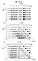
次に、図13−1を用いて、従来のサブフィールドの補正方法において、一部の画素にサブフィールドが再設定されない場合について説明する。 Next, with reference to FIG. 13A, a case where the subfield is not reset in some pixels in the conventional subfield correction method will be described.
図13−1(a)から(c)は、横軸を画素の水平位置、縦軸を時間とし、サブフィールド数Nが6の場合の表示データを表したものである。同じ画素に属するサブフィールドを同じ模様で表している。ここで、図13−1(a)において、画素(n−5)〜(n−1)が水平方向に5画素、画素n〜(n+5)が水平方向に6画素移動した場合、従来方法によりサブフィールドの発光位置を変えると、図13−1(b)のようになり、枠線の領域1310のようにサブフィールドが設定されない部分が発生する。また図13−1(a)において、画素(n−5)〜(n−1)が背景の静止領域の画素で水平方向に0画素、画素n〜(n+5)が動領域の画素で水平方向に6画素移動した場合、従来方法によりサブフィールドの発光位置を変えると、図13−1(c)のようになり、三角の枠線の領域1311内のように、サブフィールドが設定されない部分が発生する。そのため、画素の輝度が大きく変化し、画像内に存在しない輝度の異なる画素で構成された線のような模様が発生してしまう。従って、上記の例の場合、従来のサブフィールドの補正方法ではサブフィールドが設定されない画素が発生し、画質が劣化する。
FIGS. 13A to 13C show display data when the horizontal axis is the horizontal position of the pixel, the vertical axis is time, and the number N of subfields is six. Subfields belonging to the same pixel are represented by the same pattern. Here, in FIG. 13A, when the pixels (n-5) to (n-1) move 5 pixels in the horizontal direction and the pixels n to (n + 5) move 6 pixels in the horizontal direction, the conventional method is used. When the light emission position of the subfield is changed, as shown in FIG. 13-1 (b), a portion where the subfield is not set occurs, such as a
以上を踏まえて以下に本願の各実施例について説明する。 Based on the above, each embodiment of the present application will be described below.
まず、本発明の第1の実施例について図面を参照して説明する。 First, a first embodiment of the present invention will be described with reference to the drawings.
本発明の第1の実施例は、図18(a)に示すようなサブフィールド間の発光開始時間の間隔が等間隔な表示方法についての実施例である。ここで、図18は、横軸を画素の水平位置、縦軸を時間とし、サブフィールド数Nが6の場合の表示データを表したものである。
ここで、図18(a)においては、各サブフィールドの発光期間E1,E2、E3、E4、E5、に関わらず、サブフィールド間の発光開始時間の間隔はT0で一定である。
The first embodiment of the present invention is an embodiment of a display method as shown in FIG. 18A in which the intervals between the light emission start times between subfields are equal. Here, FIG. 18 shows display data when the horizontal axis is the horizontal position of the pixel, the vertical axis is time, and the number N of subfields is six.
Here, in FIG. 18A, regardless of the light emission periods E1, E2, E3, E4, and E5 of each subfield, the interval of the light emission start time between the subfields is constant at T0.
以下に詳細を説明する。 Details will be described below.
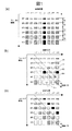
まず、図1は、横軸を画素の水平位置、縦軸を時間とし、サブフィールド数Nが6の場合の表示データを表したものである。図1(a)において、画素(n+3)の各サブフィールドの再構成について考える。 First, FIG. 1 shows display data when the horizontal axis is the horizontal position of the pixel, the vertical axis is time, and the number N of subfields is six. In FIG. 1A, the reconstruction of each subfield of the pixel (n + 3) is considered.
ここで、図1では、再構成対象の画素である画素(n+3)を終点とする動きベクトルの始点の画素は、画素(n+3)を基準とした相対位置として水平方向に−6の位置にあるとする。このとき、当該動きベクトルのベクトル値が+6である。ここで、各サブフィールド間の発光開始時間の間隔が等間隔(以降、均等間隔と呼ぶ)の場合、取得する再構成前の各サブフィールドの画素位置を、例えば再構成対象の画素を基準として以下の式1により求める。
Here, in FIG. 1, the pixel at the start point of the motion vector whose end point is the pixel (n + 3) that is the pixel to be reconstructed is at a position −6 in the horizontal direction as a relative position with respect to the pixel (n + 3). And At this time, the vector value of the motion vector is +6. Here, when the intervals of the light emission start times between the sub-fields are equal (hereinafter referred to as equal intervals), the pixel positions of the sub-fields to be acquired before reconstruction, for example, with reference to the reconstruction target pixel It calculates | requires by the following formula |

ここで、Xi は再構成対象の画素位置を基準としたときの、取得する再構成前の各サブフィールドの画素位置ベクトルである。ここで、iは再構成を行うサブフィールドの番号を示す。また、Vは動きベクトル値、Nは1TVフィールドを構成するサブフィールド数を示す。ここで、本実施例で用いる動きベクトル値Vは、再構成対象フィールドと対象フィールドよりも時間的に前のフィールド間の動きベクトルのうち、当該時間的に前のフィールドの画素を始点とし、再構成対象フィールドにおける再構成対象画素を終点とする動きベクトルを用いる。本図の例では、上述の通り+6である。当該再構成対象画素の各サブフィールドの再構成において、当該動きベクトルを用いる。
Here, Xi is a pixel position vector of each subfield to be acquired before reconstruction when the pixel position to be reconstructed is used as a reference. Here, i indicates the number of the subfield to be reconfigured. V represents a motion vector value, and N represents the number of subfields constituting one TV field. Here, the motion vector value V used in the present embodiment is re-started with a pixel in the temporally previous field among the motion vectors between the reconstruction target field and the temporally previous field as the starting point. A motion vector whose end point is the pixel to be reconstructed in the construction target field is used. In the example of this figure, it is +6 as described above. The motion vector is used in the reconstruction of each subfield of the reconstruction target pixel.
なお、位置ベクトルを算出した結果が小数精度である場合は、これを四捨五入、切捨て、切上げなどの処理により整数精度とした位置ベクトルを用いてもよい。また、小数精度のまま使用しても構わない。以下のすべての実施例において同様である。 If the result of calculating the position vector is decimal precision, a position vector having integer precision by rounding off, rounding down or rounding up may be used. Moreover, you may use it with decimal precision. The same applies to all the following examples.
本実施例では、再構成対象フィールドと対象フィールドよりも時間的に前のフィールド間の動きベクトルのうちから、当該時間的に前のフィールドの画素を始点とし再構成対象フィールドの再構成対象画素(n+3)を終点とする動きベクトルを選出し、各サブフィールドごとに数式1を用いて画素位置ベクトルの算出を行い、サブフィールドの再構成を行う。以下にこれを説明する。
In the present embodiment, a reconstruction target pixel (in a reconstruction target field (starting from a pixel in the field preceding in time) out of motion vectors between the reconstruction target field and the field preceding in time from the target field ( A motion vector whose end point is n + 3) is selected, a pixel position vector is calculated for each
図1(b)の例においては、上述の通り、再構成対象の画素である画素(n+3)を終点とする動きベクトルの始点の画素は、画素(n+3)を基準とした相対位置として水平方向に−6の位置にあり、当該動きベクトルのベクトル値が+6である。ここで、数式1を用いることにより、画素(n+3)の各サブフィールドについて画素位置ベクトルXiを算出できる。画素位置ベクトルXiはそれぞれ、SF6が−5、SF5が−4、SF4が−3、SF3が−2、SF2が−1、SF1が0となる。
In the example of FIG. 1B, as described above, the start pixel of the motion vector whose end point is the pixel (n + 3) that is the pixel to be reconstructed is the horizontal position as a relative position with respect to the pixel (n + 3). And the vector value of the motion vector is +6. Here, by using
従って、この場合、図1(b)の矢印105が示すように、SF6は画素(n−2)からサブフィールドの発光データを取得する。また、矢印104が示すように、SF5は画素(n−1)からサブフィールドの発光データを取得する。また、矢印103が示すように、SF4は画素nからサブフィールドの発光データを取得する。また、矢印102が示すように、SF3は画素(n+1)からサブフィールドの発光データを取得する。また、矢印101が示すように、SF2は画素(n+2)からサブフィールドの発光データを取得する。また、SF1はもとの画素(n+3)のサブフィールドの発光データのままとなる。
Accordingly, in this case, as indicated by the
以上のように、再構成対象画素(n+3)の各サブフィールドの発光データを再構成する。また、画素(n−4)から画素(n+2)についても、上記画素(n+3)の場合と同様に、再構成対象画素の各サブフィールドにつき、数式1を用いて画素位置ベクトルXiを算出し、求めた画素位置のサブフィールドにより、画素(n−4)から画素(n+2)の各サブフィールドを再構成することができる。このとき、再構成対象のフィールド上におけるそれぞれの画素を終点とする動きベクトルのベクトル値がいずれも同じ+6である場合は、再構成後のサブフィールドは、図1(c)に示すようになる。このとき結果として、静止画において同一の画素に配置されていた複数のサブフィールド(図1において同一の模様で示されたサブフィールド)が、各画素の再構成後は視線パス上に並ぶ。
As described above, the light emission data of each subfield of the reconstruction target pixel (n + 3) is reconstructed. For the pixels (n−4) to (n + 2), as in the case of the pixel (n + 3), the pixel position vector Xi is calculated using
このとき、第1の実施例では、各サブフィールドの発光開始時間の差を固定としている。ここで、数式1には、サブフィールドの発光開始時間やサブフィールドの発光位置(時間中心)などについてのパラメータがないため、当該再構成の演算処理は、演算量が少ないという効果がある。
At this time, in the first embodiment, the difference in the light emission start time of each subfield is fixed. Here, since
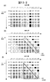
ここで、さらに従来方法と本発明の表示方法の違いについて以下で説明する。上述の通り、図13−1(b)に示す枠線の領域1310内のサブフィールドのように設定されないサブフィールドが発生する場合がある。この場合、本実施例の表示方法では、再構成対象の画素を終点とする動きベクトルを求め、それぞれのサブフィールドについて再設定を行う。これにより、サブフィールドが再設定されない画素が発生するのを防止することができる。これを図13−2(e)を用いて説明する。ここで、図13−2(d)は、図13−2(e)についての初期状態を示し、図13−1(a)と同様である。
Here, the difference between the conventional method and the display method of the present invention will be described below. As described above, a subfield that is not set may occur, such as a subfield in the
図13−2(e)の例において、再構成対象のフィールドの画素のうち画素(n−5)から画素(n−1)までの各画素を終点とする動きベクトルの始点の画素が、いずれも各画素を基準とした相対位置として水平方向に−5の位置にあるとする。このとき、当該動きベクトルのうち、いずれの動きベクトルもベクトル値が+5である。また、画素nから画素(n+5)までの各画素を終点とする動きベクトルの始点の画素が、いずれも各画素を基準とした相対位置として水平方向に−6の位置にあるとする。このとき、当該動きベクトルのうち、いずれの動きベクトルもベクトル値が+6である。この動きベクトルを用いて、各再構成対象画素において、数式1を用いて各サブフィールドごとに位置ベクトルXiを算出すると、以下のようになる。すなわち、再構成対象画素が画素(n−5)から画素(n−1)のときは、位置ベクトルXiはSF6が−4、SF5が−3、SF4が−2、SF3が−1、SF2が−1、SF1が0となる。また再構成対象画素が画素nから画素(n+5)であるときは、位置ベクトルXiはSF6が−5、SF5が−4、SF4が−3、SF3が−2、SF2が−1、SF1が0となる。
In the example of FIG. 13-2 (e), which of the pixels of the motion vector starts from each pixel from the pixel (n-5) to the pixel (n-1) among the pixels in the reconstruction target field, Also assume that the relative position with respect to each pixel is at a position of −5 in the horizontal direction. At this time, the vector value of any of the motion vectors is +5. Further, it is assumed that the start point pixel of the motion vector whose end point is each pixel from pixel n to pixel (n + 5) is at a position of −6 in the horizontal direction as a relative position with respect to each pixel. At this time, the vector value of any of the motion vectors is +6. When the position vector Xi is calculated for each
これらの各位置ベクトルXiを用いて、再構成した結果が図13−2(e)となる。このとき、枠線の領域1320内のサブフィールドも、すべて再設定されることになる。従って、図13−2(e)に示すように、視線パスを考慮した発光サブフィールドの構成としながら、全画素の全サブフィールドを再設定することができる。 The result of reconstruction using these position vectors Xi is shown in FIG. At this time, all the subfields in the frame line area 1320 are also reset. Accordingly, as shown in FIG. 13-2 (e), it is possible to reset all subfields of all pixels while adopting the configuration of the light emission subfield in consideration of the line-of-sight path.
また、上述の通り、図13−1(c)に示すように三角の枠線1311内のサブフィールドが設定されない場合がある。この場合も、本実施例の表示方法では、再構成対象の画素を終点とする動きベクトルを求め、それぞれのサブフィールドについて再設定を行う。これにより、サブフィールドが再設定されない画素が発生するのを防止することができる。これを図13−2(f)を用いて説明する。図13−2(f)についても、初期状態は図13−2(d)である。
Further, as described above, as shown in FIG. 13-1 (c), the subfield in the
図13−2(f)の例において、再構成対象のフィールドの画素のうち画素(n−5)から画素(n−1)までの各画素を終点とする動きベクトルの始点の画素が、いずれも各画素を基準とした相対位置として水平方向0の位置にあるとする。このとき、当該動きベクトルのうち、いずれの動きベクトルもベクトル値が0である。また、画素nから画素(n+5)までの各画素を終点とする動きベクトルの始点の画素が、いずれも各画素を基準とした相対位置として水平方向に−6の位置にあるとする。このとき、当該動きベクトルのうち、いずれの動きベクトルもベクトル値が+6である。この動きベクトルを用いて、各再構成対象画素において、数式1を用いて各サブフィールドごとに位置ベクトルXiを算出すると、以下のようになる。すなわち、再構成対象画素が画素(n−5)から画素(n−1)のときは、位置ベクトルXiはSF6、SF5、SF4、SF3、SF2、SF1のいずれも0となる。また再構成対象画素が画素nから画素(n+5)であるときは、位置ベクトルXiはSF6が−5、SF5が−4、SF4が−3、SF3が−2、SF2が−1、SF1が0となる。
In the example of FIG. 13-2 (f), the start pixel of the motion vector whose end point is each pixel from the pixel (n-5) to the pixel (n-1) among the pixels in the reconstruction target field Also, it is assumed that it is at a position in the
これらの各位置ベクトルXiを用いて、再構成した結果が図13−2(f)となる。このとき、三角形の枠線の領域1321内のサブフィールドも、すべて再設定されることになる。従って、図13−2(f)に示すように、視線パスを考慮した発光サブフィールドの構成としながら、全画素の全サブフィールドを再設定することができる。
The result of reconstruction using these position vectors Xi is shown in FIG. At this time, all the subfields in the
このとき、第1の実施例に係るサブフィールドの設定方法によれば、視線パスを考慮して発光サブフィールドの配置をしながら、全画素の全サブフィールドが再設定される。これにより、動画ボヤケや動画擬似輪郭の発生を抑制しながら、サブフィールドの未配置を防止することができる。 At this time, according to the subfield setting method according to the first embodiment, all subfields of all pixels are reset while arranging the light emitting subfields in consideration of the line-of-sight path. Thereby, it is possible to prevent subfields from being unallocated while suppressing the occurrence of moving image blur and moving image pseudo contour.
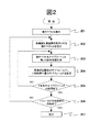
次に上記の手順を図2のフローチャートに示す。先ず、ステップ201にて、対象フィールドの表示データと、前記対象フィールドより時間的に前のフィールドの表示データとを比較し、前記時間的に前のフィールドの画素を始点とし、前記対象フィールドの画素を終点とする動きベクトルを、前記対象フィールドの各画素について検出する。次にステップ202において、ステップ201において検出した動きベクトルのうち、対象となる一の画素を終点とする動きベクトルを選出する。次に、ステップ203にて、これから再設定を行う一の画素の一のサブフィールドについて、ステップ202で選出した動きベクトルと対象サブフィールドの番号や数を用いて、例えば、数式1から取得する再設定前のサブフィールドの画素位置ベクトルを求める。さらに、ステップ204にて再構成画素の対象サブフィールドに、求めた画素位置ベクトルの示す画素における同じ番号のサブフィールドの発光データを設定する。次に、ステップ205において、当該一の画素の全てのサブフィールドについて再設定したか否かを判定する。また、全てのサブフィールドについて再設定していれば、ステップ206に進む。そうでなければ、残りのサブフィールドについて、ステップ203およびステップ204の処理をおこなう。また、ステップ206においては、対象フィールドの全ての画素についてサブフィールドの再設定が完了したかを判定する。全ての画素についてサブフィールドの再設定が完了していれば、ステップ207に進む。そうでなければ、残りの画素について、ステップ202〜205の処理をおこなう。ステップ207では、ステップ206で得られた対象フィールドの表示データを表示する。
Next, the above procedure is shown in the flowchart of FIG. First, in
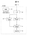
図14は、本発明の第1の実施例に係る表示装置の一例を示すブロック図である。図14の表示装置は、例えば、入力部1400、動きベクトル検出部1410、サブフィールド変換部1420、サブフィールド再構成部1440、画像表示部1450、制御部1460を備えている。
FIG. 14 is a block diagram showing an example of a display device according to the first embodiment of the present invention. The display device of FIG. 14 includes, for example, an
次に各部の動作の詳細を説明する。まず、入力部1400には動画像データが入力される。例えば入力部は、TV放送用のチューナー、画像入力端子、ネットワーク接続端子などを備える。また、入力された動画像データに従来技術の変換処理等を行い、変換処理後の表示データをベクトル検出部1410に対して出力する。次に、動きベクトル検出部1410では、対象フィールドの表示データと、前記対象フィールドより時間的に前のフィールドの表示データとを比較することで、対象フィールドの各画素を終点とする動きベクトルを検出する。図2のステップ201およびステップ202は、例えば動きベクトル検出部1410で行われる。サブフィールド変換部1420では、表示データをサブフィールドデータに変換する。サブフィールド再構成部1440では、前記動きベクトル検出部1410で検出した動きベクトルのうちの対象フィールドの再構成対象画素を終点とする動きベクトル、サブフィールドの数や番号を用いて、数式1により、再構成対象の画素の一のサブフィールドを再配置するための、再構成前のサブフィールドの画素位置を計算する。さらに、サブフィールド再構成部1440は、サブフィールド変換部1420が出力するサブフィールドデータのうち前記画素位置におけるサブフィールドの発光データを取得する。取得した発光データを再構成対象のサブフィールドに配置する再構成をおこなう。これを繰り返すことにより、1画素毎にサブフィールドを再構成し、サブフィールド変換部1420が出力したサブフィールドデータを再構成する。図2のステップ203、204および205は、例えば、サブフィールド再構成部1440で行われる。さらに、画像表示部1450は、点灯および消灯などの発光動作を行う複数の画素を有する。ここで、画像表示部1450は、前記サブフィールド再構成部1440で求めたサブフィールドデータに基づいて、各画素の点灯または消灯を制御し、画像を表示する。図2のステップ207は、例えば、画像表示部1450で行われる。また図14において、制御部1460は例えば、図14の表示装置の各要素に接続される。図14の表示装置の各要素の動作は、上述した通り、各構成要素の自律的な動作としても良いが、また、例えば制御部1460の指示により動作しても構わない。また、図2のステップ205、206などは、例えば、制御部1460が行ってもよい。
Next, details of the operation of each unit will be described. First, moving image data is input to the
以上説明した第1の実施例の表示方法によって、一つの対象フィールドを一の新たなフィールドとして再構成することができる。対象フィールドを代えながら当該処理を繰り返すことにより、新たな複数のフィールドを生成して画像を表示することができる。 One target field can be reconfigured as one new field by the display method of the first embodiment described above. By repeating the process while changing the target field, a plurality of new fields can be generated and an image can be displayed.
以上説明した第1の実施例によれば、動きベクトルによる視線パスを考慮したサブフィールド再構成が実現でき、動画ボヤケや動画擬似輪郭の発生を抑制できる。また、設定されないサブフィールドの発生を防止することができる。さらに、これらを回路処理量の低減とともに実現することが可能となる。 According to the first embodiment described above, subfield reconstruction can be realized in consideration of a line-of-sight path based on a motion vector, and generation of moving image blur and moving image pseudo contour can be suppressed. In addition, it is possible to prevent occurrence of subfields that are not set. Furthermore, these can be realized with a reduction in circuit throughput.
次に、本発明の第2の実施例について説明する。 Next, a second embodiment of the present invention will be described.
第1の実施例では、各サブフィールド間の発光開始時間の間隔が、等間隔かつ固定である場合について説明した。これに対し、本発明の第2の実施例は、図18(b)に示すような、発光期間を考慮して、当該発光開始時間の間隔を可変とする表示方法の場合の例である。
ここで、図18(b)においては、各サブフィールド間の発光開始時間の時間間隔T1、T2、T3、T4、T5は、それぞれ各サブフィールドの発光期間E1’, E2’, E3’, E4’, E5’に応じて可変する。ここで、発光期間E1’, E2’, E3’, E4’, E5’に応じて可変するとは、例えば、時間間隔T1、T2、T3、T4、T5は、発光期間E1’, E2’, E3’, E4’, E5’のそれぞれを変数とする関数の値などにより定められることをいう。よって、第1の実施例と異なり、本実施例で用いる各サブフィールド間の発光開始時間の間隔T1、T2、T3、T4、T5は、は同一の時間長ではない。
In the first embodiment, the case has been described in which the intervals of the light emission start times between the subfields are equal and fixed. In contrast, the second embodiment of the present invention is an example of a display method in which the interval of the light emission start time is variable in consideration of the light emission period, as shown in FIG.
Here, in FIG. 18B, the time intervals T1, T2, T3, T4, and T5 of the light emission start times between the subfields are the light emission periods E1 ′, E2 ′, E3 ′, and E4 of the subfields, respectively. Variable according to ', E5'. Here, the variable according to the light emission periods E1 ′, E2 ′, E3 ′, E4 ′, E5 ′ means that, for example, the time intervals T1, T2, T3, T4, T5 are the light emission periods E1 ′, E2 ′, E3. It means that it is determined by the value of a function with each of ', E4' and E5 'as variables. Therefore, unlike the first embodiment, the intervals T1, T2, T3, T4, and T5 of the light emission start times between the subfields used in this embodiment are not the same time length.
ここで、当該発光開始時間の間隔を可変とする意義を説明する。まず、各サブフィールドの発光、非発光を制御することで、1フィールドの画像を表示する表示装置のうち、例えばプラズマテレビなどでは、電力を一定にする処理を行うことがある。この処理を行うとき、各サブフィールドの発光開始時間の位置関係は入力画像の表示負荷率に応じて変化する。ここで表示負荷率とは、例えば画面の平均輝度などの画面輝度のパラメータに応じてサステイン期間を調整する際のパラメータである。ここで、例えば、表示負荷率が大きいときに、例えば図10のサステイン期間を短くし、表示負荷率が小さいときは当該サステイン期間を長くすることにより、電力を一定にする処理を実現することができる。そのため、発光開始時間の間隔を可変とする表示方法が行われる。 Here, the significance of making the interval of the light emission start time variable will be described. First, by controlling light emission and non-light emission of each subfield, a display device that displays an image of one field, for example, in a plasma television, may perform a process of making power constant. When this process is performed, the positional relationship between the light emission start times of the subfields changes according to the display load factor of the input image. Here, the display load factor is a parameter for adjusting the sustain period in accordance with a screen brightness parameter such as an average screen brightness. Here, for example, when the display load factor is large, for example, the sustain period of FIG. 10 is shortened, and when the display load factor is small, the sustain period is lengthened, thereby realizing the process of making the power constant. it can. Therefore, a display method in which the interval of the light emission start time is variable is performed.
ここで、画面の平均輝度などに応じて、表示負荷が変化するときのユーザーの視線方向の傾きについて説明する。まず、静止画における視線はサブフィールド期間が経過しても移動しない。よって、同一画素上にとどまることになる。このときの視線パスの傾きを0とする。 Here, the inclination of the user's line-of-sight direction when the display load changes according to the average luminance of the screen will be described. First, the line of sight in a still image does not move even after the subfield period has elapsed. Therefore, it remains on the same pixel. The inclination of the line-of-sight path at this time is set to zero.
ここで、例えば、表示負荷が大きいときは、各サブフィールドの発光期間が短くなる。このとき上記表示装置は、各サブフィールドを順番に詰めて発光する。これにより、各サブフィールドの発光開始時間が1TVフィールド期間内で早くなる。従って、視線方向の傾きは小さくなる。 Here, for example, when the display load is large, the light emission period of each subfield is shortened. At this time, the display device emits light by closing the subfields in order. As a result, the light emission start time of each subfield is shortened within one TV field period. Accordingly, the inclination in the line-of-sight direction becomes small.
一方、例えば、表示負荷が小さいときは、各サブフィールドの発光期間が長くなる。上記表示装置では、各サブフィールドの発光開始時間が1TVフィールド期間内で遅くなる。従って、視線方向の傾きは大きくなる。 On the other hand, for example, when the display load is small, the light emission period of each subfield becomes long. In the display device, the light emission start time of each subfield is delayed within one TV field period. Therefore, the inclination in the line of sight increases.
ここで、以下の説明においては、表示負荷が大きく、均等間隔での各サブフィールドの発光開始時間より早くサブフィールドが発光し、視線パスの傾きが小さくなるときを例として説明をする。 Here, in the following description, the case where the display load is large, the subfield emits light earlier than the emission start time of each subfield at equal intervals, and the inclination of the line-of-sight path becomes small will be described as an example.
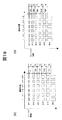
ここで、例えば、表1に示す「発光考慮間隔での各SFの発光開始時間(ms)」のテーブルを、平均輝度レベルごとに予め複数用意しておく。そして、画像表示前に、その画像の平均輝度レベルを求めることで、画像の表示負荷率により変化するサブフィールドの発光位置の間隔を遅延無くダイナミックに求めることができる。これにより、回路規模を小さくすることが可能となる。
Here, for example, a plurality of tables of “emission start time (ms) of each SF at the emission consideration interval” shown in Table 1 are prepared in advance for each average luminance level. Then, by obtaining the average luminance level of the image before displaying the image, it is possible to dynamically obtain the interval between the light emission positions of the subfields that change depending on the display load factor of the image without delay. As a result, the circuit scale can be reduced.
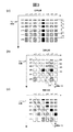
ここで、1フィールドの表示時間(60Hz画像の場合、16.67ms)に対する1フィールドの先頭からの各サブフィールドの発光開始時間が、表1の(2)のである場合を例としサブフィールドの再構成について図3を用いて説明する。
Here, a case where the emission start time of each subfield from the head of one field with respect to the display time of one field (16.67 ms in the case of a 60 Hz image) is (2) in Table 1 is taken as an example. The configuration will be described with reference to FIG.
図3は、画素(n+2)の各サブフィールドの再構成を説明した図である。再設定をする前のサブフィールドの発光データを図3(a)に示している。
ここで、図3では、再構成対象の画素である画素(n+2)を終点とする動きベクトルの始点の画素は、画素(n+2)を基準とした相対位置として水平方向に−6の位置にあるとする。このとき、当該動きベクトルのベクトル値が+6である。
FIG. 3 is a diagram for explaining the reconstruction of each subfield of the pixel (n + 2). The light emission data of the subfield before resetting is shown in FIG.
Here, in FIG. 3, the pixel at the start point of the motion vector whose end point is the pixel (n + 2) that is the pixel to be reconstructed is at a position −6 in the horizontal direction as a relative position with respect to the pixel (n + 2). And At this time, the vector value of the motion vector is +6.
このとき、図3の例では、表1の(2)に示される発光サブフィールドの時間を考慮した発光考慮間隔の場合である。ここで本実施例では、取得する再構成前の各サブフィールドの画素位置を、例えば再構成対象の画素を基準として数式2により求める。
At this time, the example of FIG. 3 is a case of the light emission consideration interval in consideration of the time of the light emission subfield shown in (1) of Table 1. Here, in the present embodiment, the pixel position of each subfield to be acquired before reconstruction is obtained by
ここで、Xiは再構成対象の画素位置を基準としたときの、取得する再構成前の各サブフィールドの画素位置ベクトルである。ここで、iは再構成を行うサブフィールドの番号を示す。また、Vは動きベクトル値を示す。ここで、本実施例で用いる動きベクトル値Vは、
再構成対象フィールドと対象フィールドよりも時間的に前のフィールド間の動きベクトルのうち、当該時間的に前のフィールドの画素を始点とし、再構成対象フィールドにおける再構成対象画素を終点とする動きベクトルを用いる。当該再構成対象画素の各サブフィールドの再構成において、当該動きベクトルを用いる。また、Siは、i番目のSFの発光開始時間を示し、例えば、表1の(2)に示されるものである。さらにTfは、1TVフィールド期間を示す。
Here, Xi is a pixel position vector of each subfield to be acquired before reconstruction when the pixel position to be reconstructed is used as a reference. Here, i indicates the number of the subfield to be reconfigured. V represents a motion vector value. Here, the motion vector value V used in this embodiment is
Of the motion vectors between the reconstruction target field and the field preceding the target field, the motion vector starting from the pixel of the previous field in time and having the reconstruction target pixel in the reconstruction target field as the end point Is used. The motion vector is used in the reconstruction of each subfield of the reconstruction target pixel. Si indicates the light emission start time of the i-th SF, and is shown in (2) of Table 1, for example. Further, Tf represents one TV field period.
数式2に含まれる各SFの発光開始時間パラメータは、同一フィールド内の各サブフィールドの発光期間により可変である。よって当該パラメータを用いることにより、サブフィールドの発光期間を考慮した再構成を実現することができる。
The light emission start time parameter of each SF included in
本実施例では、再構成対象フィールドと対象フィールドよりも時間的に前のフィールド間の動きベクトルのうちから、当該時間的に前のフィールドの画素を始点とし再構成対象フィールドの再構成対象画素(n+2)を終点とする動きベクトルを選出し、数式2を用いた前記画素位置ベクトルの算出を行い、サブフィールドの再構成を行う。以下にこれを説明する。
In the present embodiment, a reconstruction target pixel (in a reconstruction target field (starting from a pixel in the field preceding in time) out of motion vectors between the reconstruction target field and the field preceding in time from the target field ( A motion vector whose end point is n + 2) is selected, the pixel position vector is calculated using
図3(b)の例においては、上述の通り、再構成対象の画素である画素(n+2)を終点とする動きベクトルの始点の画素は、画素(n+2)を基準とした相対位置として水平方向に−6の位置にあり、当該動きベクトルのベクトル値が+6である。ここで、数式2を用いることにより、画素(n+2)の各サブフィールドについて画素位置ベクトルXiを算出できる。画素位置ベクトルXiはそれぞれ、SF6が−4、SF5が−3、SF4が−2、SF3が−1、SF2が−1、SF1が0となる。
In the example of FIG. 3B, as described above, the starting pixel of the motion vector whose end point is the pixel (n + 2) that is the pixel to be reconstructed is the horizontal position as a relative position with respect to the pixel (n + 2). And the vector value of the motion vector is +6. Here, by using
従って、この場合、図3(b)の矢印305が示すように、SF6は画素(n−2)からサブフィールドの発光データを取得する。また、矢印304が示すように、SF5は画素(n−1)からサブフィールドの発光データを取得する。また、矢印303に示すように、SF4は画素nからサブフィールドの発光データを取得する。また、矢印302が示すように、SF3は画素(n+1)からサブフィールドの発光データを取得する。また、矢印301が示すように、SF2も画素(n+1)からサブフィールドの発光データを取得する。また、SF1はもとの画素(n+2)からサブフィールドの発光データを取得する。以上のように、画素(n+2)を再構成する。
Therefore, in this case, as indicated by the
以上のように、再構成対象画素(n+2)の各サブフィールドの発光データを再構成する。また、他の画素についても、上記画素(n+2)の場合と同様に、再構成対象画素の各サブフィールドにつき、数式2を用いて画素位置ベクトルXiを算出し、求めた画素位置のサブフィールドにより、各画素の各サブフィールドを再構成することができる。このとき、再構成対象のフィールド上におけるそれぞれの画素を終点とする動きベクトルの始点の画素が、上記画素(n+2)と同じく、再構成対象画素を基準とした相対位置として水平方向に−6の位置にあり、いずれの動きベクトルもベクトル値が+6である場合は、再構成後のサブフィールドは、図3(c)に示すようになる。このとき結果として、静止画において同一の画素に配置されていた複数のサブフィールド(図3において同一の模様で示されたサブフィールド)が、各画素の再構成後は視線パス上に並ぶ。
As described above, the light emission data of each subfield of the reconstruction target pixel (n + 2) is reconstructed. For other pixels, as in the case of the pixel (n + 2), the pixel position vector Xi is calculated using
本実施例のように、動きベクトルとサブフィールドの発光間隔から求めた画素位置ベクトルを用いてサブフィールドを再構成すれば、仮に静止画であるとするときに同一の画素に配置される複数のサブフィールドを視線パス上に並べることができる。このとき、本実施例では、動きベクトルとサブフィールドの発光間隔をパラメータとしてサブフィールドを再構成しているので、サブフィールドの発光間隔が可変である場合であっても、サブフィールドの発光パターンが、ユーザーが画像を見る際の視線パス上により好適に整列することになる。これにより動画ボヤケや動画擬似輪郭の発生を抑制できる。 If the subfield is reconstructed using the pixel position vector obtained from the motion vector and the emission interval of the subfield as in this embodiment, a plurality of pixels arranged in the same pixel are assumed to be still images. Subfields can be arranged on the line-of-sight path. At this time, in this embodiment, since the subfield is reconfigured using the motion vector and the light emission interval of the subfield as parameters, even if the light emission interval of the subfield is variable, the light emission pattern of the subfield is Thus, the user can better align the line of sight when viewing the image. Thereby, generation | occurrence | production of a moving image blur and a moving image pseudo contour can be suppressed.
また、第2の実施例は、第1の実施例と同様に再構成対象の画素を終点とする動きベクトルを求め、当該画素のそれぞれのサブフィールドについて再構成を行う。これにより、サブフィールドが再構成されない画素が発生するのを防止することができる。この効果は第1の実施例と同様である。 Further, in the second embodiment, similarly to the first embodiment, a motion vector whose end point is a pixel to be reconstructed is obtained, and reconfiguration is performed for each subfield of the pixel. Thereby, it is possible to prevent the occurrence of pixels in which the subfield is not reconstructed. This effect is the same as that of the first embodiment.
このとき、平均輝度レベルに対応した各サブフィールドの発光位置に関するテーブルを用いることにより、画像の表示負荷率などに応じたサブフィールドの発光位置の間隔の算出に係る処理量を低減できる。これにより、当該再構成に係る演算処理の演算量をより少なくすることができる。 At this time, by using the table regarding the light emission position of each subfield corresponding to the average luminance level, it is possible to reduce the amount of processing related to the calculation of the interval between the light emission positions of the subfield according to the display load factor of the image. Thereby, it is possible to further reduce the calculation amount of the calculation process related to the reconfiguration.
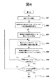
次に、本実施例の動作手順を図4のフローチャートに示す。先ず、ステップ401にて、対象フィールドの表示データと、前記対象フィールドより時間的に前のフィールドの表示データとを比較し、前記時間的に前のフィールドの画素を始点とし、前記対象フィールドの画素を終点とする動きベクトルを、前記対象フィールドの各画素について検出する。次にステップ402にて、平均輝度レベルに対応した各サブフィールドの発光位置に関するテーブルを用いて、表示データの表示負荷率より変化する各サブフィールドの発光開始時間を算出する。次にステップ403において、ステップ401において検出した動きベクトルのうち、対象となる一の画素を終点とする動きベクトルを選出する。さらに、ステップ404にて、ステップ403で選出した動きベクトルと1TVフィールド期間と対象サブフィールドの発光開始時間とをパラメータとして、数式2を用いて取得する再設定前のサブフィールドの画素位置ベクトルを求める。さらに、ステップ405において、再構成先の画素の対象サブフィールドに、求めた画素位置ベクトルの示す画素における同じ番号のサブフィールドの発光データを設定する。次に、ステップ406において、当該一の画素の全てのサブフィールドについて再設定したか否かを判定する。また、全てのサブフィールドについて再設定していれば、ステップ407に進む。そうでなければ、残りのサブフィールドについて、ステップ404およびステップ405の処理をおこなう。また、ステップ407においては、対象フィールドの全ての画素についてサブフィールドの再設定が完了したかを判定する。全ての画素についてサブフィールドの再設定が完了していれば、ステップ408に進む。そうでなければ、残りの画素について、ステップ403〜406の処理をおこなう。ステップ408では、ステップ407で得られた対象フィールドの表示データを表示する。
Next, the operation procedure of this embodiment is shown in the flowchart of FIG. First, in
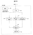
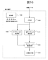
図15は、本発明の第2の実施例に係る表示装置の一例を示すブロック図である。図15の表示装置は、例えば、入力部1400、動きベクトル検出部1410、サブフィールド変換部1420、サブフィールド発光時間算出部1530、サブフィールド再構成部1540、画像表示部1450、制御部1460を備えている。
FIG. 15 is a block diagram showing an example of a display device according to the second embodiment of the present invention. 15 includes, for example, an
次に各部の動作の詳細を説明する。まず、入力部1400には動画像データが入力される。例えば入力部は、TV放送用のチューナー、画像入力端子、ネットワーク接続端子などを備える。また、入力された動画像データに従来技術の変換処理等を行い、変換処理後の表示データをベクトル検出部1410に対して出力する。次に、動きベクトル検出部1410では、対象フィールドの表示データと、前記対象フィールドより時間的に前のフィールドの表示データとを比較することで対象フィールドの各画素を終点とする動きベクトルを検出する。図4のステップ401およびステップ403は、例えば動きベクトル検出部1410で行われる。サブフィールド変換部1420では、表示データをサブフィールドデータに変換する。ここで、サブフィールド発光時間算出部1530では、例えば、画像の表示負荷率に応じて変化する各サブフィールドの発光開始時間を求める。図4のステップ402は、例えばサブフィールド発光時間算出部1530で行われる。サブフィールド再構成部1540では、前記動きベクトル検出部1410で検出した動きベクトルのうちの対象フィールドの再構成対象画素を終点とする動きベクトル、前記サブフィールド発光時間算出部1530で求めた各サブフィールドの発光開始時間、1TVフィールド期間等をパラメータとして、数式2により、再構成対象の画素の一のサブフィールドに再配置するための、再構成前のサブフィールドの画素位置を計算する。さらに、サブフィールド再構成部1540は、サブフィールド変換部1420から出力されるサブフィールドデータの前記画素位置におけるサブフィールドの発光データを取得する。取得した発光データを再構成対象のサブフィールドに再配置する。これを繰り返すことにより、1画素毎にサブフィールドを再構成し、サブフィールド変換部1420で求めたサブフィールドデータを再構成する。図4のステップ404、405および406は、例えば、サブフィールド再構成部1540で行われる。次に、画像表示部1450は、点灯および消灯などの発光動作を行う複数の画素を有する。ここで、画像表示部1450は、前記サブフィールド再構成部1540で求めたサブフィールドデータに基づいて、各画素の点灯または消灯を制御し、画像を表示する。図4のステップ408は、例えば、画像表示部1450で行われる。また図15において、制御部1460は例えば、図15の表示装置の各要素に接続される。図15の表示装置の各要素の動作は、上述した通り、各構成要素の自律的な動作としても良いが、また、例えば制御部1460の指示により動作しても構わない。また、図4のステップ406、407などは、例えば、制御部1460が行ってもよい。
Next, details of the operation of each unit will be described. First, moving image data is input to the
以上説明した第2の実施例の表示方法によって、一つの対象フィールドを一の新たなフィールドとして再構成することができる。対象フィールドを代えながら当該処理を繰り返すことにより、新たな複数のフィールドを生成して画像を表示することができる。 One target field can be reconfigured as one new field by the display method of the second embodiment described above. By repeating the process while changing the target field, a plurality of new fields can be generated and an image can be displayed.
以上説明した第2の実施例によれば、画像の表示負荷率などに応じて各サブフィールドの発光開始時間を可変とする表示方法においても、ユーザーの視線が発光するサブフィールド上をより好適にトレースするように、サブフィールドの再構成が実現できる。これにより、動画ボヤケや動画擬似輪郭の発生をより好適に抑制できる。また、設定されないサブフィールドの発生を防止することができる。また、これらをより少ない演算量で実現することができる。 According to the second embodiment described above, even in a display method in which the light emission start time of each subfield is made variable according to the display load factor of the image, the subfield where the user's line of sight emits light is more suitably used. Sub-field reconstruction can be achieved as traced. Thereby, generation | occurrence | production of moving image blur and a moving image pseudo contour can be suppressed more suitably. In addition, it is possible to prevent occurrence of subfields that are not set. Also, these can be realized with a smaller amount of calculation.
上記の例では、均等間隔での各サブフィールドの発光開始時間より早くサブフィールドが発光する例について説明をした。しかし、均等間隔での各サブフィールドの発光開始時間より遅くサブフィールドが発光し、視線パスの傾きが大きくなる場合であっても、数式2を用いたサブフィールドの再構成を行うことにより、同様の効果が得られる。
In the above example, the example in which the subfield emits light earlier than the light emission start time of each subfield at equal intervals has been described. However, even if the subfield emits light later than the light emission start time of each subfield at equal intervals and the inclination of the line-of-sight path increases, the same can be achieved by reconstructing the
次に、本発明の第3の実施例について説明する。本発明の第3の実施例に係る表示方法では、第1の実施例と同じく、各サブフィールド間の発光開始時間の間隔を等間隔に固定したものである。 Next, a third embodiment of the present invention will be described. In the display method according to the third embodiment of the present invention, as in the first embodiment, the intervals of the light emission start times between the subfields are fixed at equal intervals.
本発明の第3の実施例に係る表示方法に使用する動きベクトルFについて、図5を用いて説明する。この動きベクトルFは、現フィールドCと前フィールドAの間に位置する中間フィールドBの画素が前フィールドAのどの画素から移動してきたかを示すベクトルである。すなわち、図5において、中間フィールドBの画素bを終点とし、前フィールドAの画素aを始点とする動きベクトルである。 A motion vector F used in the display method according to the third embodiment of the present invention will be described with reference to FIG. This motion vector F is a vector indicating from which pixel in the previous field A the pixels in the intermediate field B located between the current field C and the previous field A have moved. That is, in FIG. 5, the motion vector has the pixel b in the intermediate field B as the end point and the pixel a in the previous field A as the start point.
ここで、入力動画像のうちの複数のフィールドから、当該ベクトルFを算出する方法や、中間フィールドを生成する方法については、例えば、参考文献1の図3等に記載される従来の方法を用いればよい。 Here, as a method for calculating the vector F from a plurality of fields of the input moving image and a method for generating an intermediate field, for example, a conventional method described in FIG. That's fine.
(参考文献1)特開2006−310985
例えば、図5においては、現フィールドCと前のフィールドAの画像パターンの相関から動き量を推定して、画素aから画素cへの動きベクトルEを求めることができる。前フィールドAと中間フィールドBとの時間的距離(期間)をTm、前フィールドAと現フィールドCとの時間的距離(期間)をTfとしたとき、前フィールドAと中間フィールドBとの時間的距離(期間)はTf-Tmである。このとき、画素aから画素bへの移動量に相当する動きベクトルFは数式3により求めることができる。
(Reference Document 1) JP-A-2006-310985
For example, in FIG. 5, the motion vector E from the pixel a to the pixel c can be obtained by estimating the motion amount from the correlation between the image patterns of the current field C and the previous field A. When the temporal distance (period) between the previous field A and the intermediate field B is Tm, and the temporal distance (period) between the previous field A and the current field C is Tf, the temporal distance between the previous field A and the intermediate field B is The distance (period) is Tf−Tm. At this time, the motion vector F corresponding to the amount of movement from the pixel a to the pixel b can be obtained by
ここで、Vfはここで動きベクトルFのベクトル値、Vは動きベクトルEのベクトル値である。例えば、TmがTfの半分の期間で、かつ動きベクトルEのベクトル値Vが+4である場合、動きベクトルFのベクトル値Vfは+2となる。なお、中間フィールドBの画素を生成しなくとも、例えば、数式3により動きベクトルFを求めることができる。
Here, Vf is a vector value of the motion vector F and V is a vector value of the motion vector E. For example, when Tm is a half period of Tf and the vector value V of the motion vector E is +4, the vector value Vf of the motion vector F is +2. For example, the motion vector F can be obtained by
また、図5においては、例えば、前フィールドAの画素aと現フィールドCの画素cの平均値もしくは中間フィールドまでの距離を考慮した加重平均などの両画素の画素値を変数とする関数値を求めて動きベクトルFが示す位置に、中間フィールドBの画素bを出力することができる。同様に、前フィールドAの各画素から現フィールドCの各画素への動きベクトルEを用いて、中間フィールドの各画素を生成することもできる。 In FIG. 5, for example, function values having the pixel values of both pixels as variables, such as an average value of the pixel a of the previous field A and the pixel c of the current field C or a weighted average considering the distance to the intermediate field, are used. The pixel b in the intermediate field B can be output at the position indicated by the motion vector F. Similarly, each pixel in the intermediate field can be generated using the motion vector E from each pixel in the previous field A to each pixel in the current field C.
なお、本実施例におけるサブフィールドの再構成は、いずれも上記の動きベクトルFを用いるが、サブフィールドの再構成をおこなう対象フィールドは、以下の3つのいずれかを用いればよい。 Note that the subfield reconstruction in the present embodiment uses the above-described motion vector F, but the target field for the subfield reconstruction may be any of the following three.
第1の方式は、上述のように生成した中間フィールドBをサブフィールド再構成の対象フィールドとする方式である。このとき、対象フィールドと動きベクトルFの関係は以下の通りとなる。すなわち、サブフィールド再構成は映像信号に含まれる二つのフィールド(前フィールドAと現フィールドC)の間に配置される中間フィールドBを対象フィールドとする。ここで当該二つのフィールドのうち、時間的に前のフィールドである前フィールドAの画素を始点とし、前記中間フィールドBの画素を終点とする動きベクトルを動きベクトルFとして算出する。当該動きベクトルFを用いて対象フィールドである中間フィールドBのサブフィールドを再構成する。このとき、第1の方式は再構成に用いる動きベクトルFは中間フィールドBの画素を終点としているため、原理上、最も好適な方式である。 The first method is a method in which the intermediate field B generated as described above is a target field for subfield reconstruction. At this time, the relationship between the target field and the motion vector F is as follows. That is, the subfield reconstruction uses the intermediate field B arranged between two fields (previous field A and current field C) included in the video signal as the target field. Here, of the two fields, a motion vector starting from the pixel in the previous field A, which is the previous field in time, and starting from the pixel in the intermediate field B is calculated as the motion vector F. The motion field F is used to reconstruct the subfield of the intermediate field B that is the target field. At this time, the first method is the most preferable method in principle because the motion vector F used for reconstruction has a pixel in the intermediate field B as an end point.
第2の方式は、前記前フィールドAを対象フィールドとする方式である。このとき、対象フィールドと動きベクトルFの関係は以下の通りとなる。すなわち、サブフィールド再構成は映像信号に含まれる二つのフィールド(前フィールドAと現フィールドC)のうち、時間的に前のフィールドである前フィールドAを対象フィールドとする。次に、例えば、数式3により動きベクトルFを算出する。また、当該動きベクトルFを用いて対象フィールドである前フィールドAのサブフィールドを再構成する。ここで、第2の方式では、対象フィールドである前フィールドAは中間フィールドBと近接したフィールドである。よって、この動きベクトルFを流用して再構成することにより、再構成後の動画像は、第1の方式と同等のものを得ることができる。さらに、第2の方式では、中間フィールドBの画素の値を用いる必要が無い。よって、中間フィールドの各画素の生成を行う必要が無く、演算量の低減が可能であるという効果がある。
The second method is a method in which the previous field A is the target field. At this time, the relationship between the target field and the motion vector F is as follows. That is, the subfield reconstruction uses the previous field A, which is the previous field in time, among the two fields (the previous field A and the current field C) included in the video signal. Next, for example, the motion vector F is calculated by
第3の方式は、前記現フィールドCを対象フィールドとする方式である。このとき、対象フィールドと動きベクトルFの関係は以下の通りとなる。すなわち、サブフィールド再構成は映像信号に含まれる二つのフィールド(前フィールドAと現フィールドC)のうち、時間的に後のフィールドである現フィールドCを対象フィールドとする。次に、例えば、数式3により動きベクトルFを算出する。また、当該動きベクトルFを用いて対象フィールドである現フィールドCのサブフィールドを再構成する。ここで、第3の方式では第2の方式と同じく、対象フィールドである現フィールドCは中間フィールドBと近接したフィールドである。よって、この動きベクトルFを流用して再構成することにより、再構成後の動画像は、第1の方式と同等のものを得ることができる。さらに、第3の方式では第2の方式と同じく、中間フィールドBの画素の値を用いる必要が無い。よって、中間フィールドの各画素の生成を行う必要が無く、演算量の低減が可能であるという効果がある。
The third method is a method in which the current field C is the target field. At this time, the relationship between the target field and the motion vector F is as follows. That is, in the subfield reconstruction, the current field C that is a temporally subsequent field among the two fields (the previous field A and the current field C) included in the video signal is set as the target field. Next, for example, the motion vector F is calculated by
以上説明したように、サブフィールド再構成の対象フィールドは上記の3つの方式のいずれを用いてもよい。よって、本実施例の以下の説明において単に「対象フィールド」として説明するが、この「対象フィールド」は図5の前フィールドA、中間フィールドB、現フィールドCのいずれであっても構わない。 As described above, any of the above three methods may be used for the target field for subfield reconstruction. Therefore, in the following description of the present embodiment, description will be made simply as “target field”, but this “target field” may be any of the previous field A, intermediate field B, and current field C in FIG.
ここで、図6(a)を用いて、本実施例によるサブフィールドの再構成について説明する。図6(a)は、対象フィールドのサブフィールドの表示データを示した図であり、横軸を画素の水平位置、縦軸を時間とし、サブフィールド数Nが6の場合を表したものである。ここでは、対象フィールドの画素nの各サブフィールドの再構成について考える。 Here, with reference to FIG. 6A, subfield reconstruction according to the present embodiment will be described. FIG. 6A is a diagram showing display data of a subfield of the target field, and shows a case where the horizontal axis is the horizontal position of the pixel, the vertical axis is time, and the number N of subfields is 6. . Here, the reconstruction of each subfield of the pixel n of the target field is considered.
まず、本実施例では、図5において、前フィールドAの画素を始点とし、中間フィールドBの画素nを通過し、現フィールドCの画素を終点とする動きベクトルにおいて、当該終点の画素を基準とした当該始点の画素の相対位置が水平方向に−6であるとする。また、このときの動きベクトルEのベクトル値は+6となる。ここで、図5における中間フィールドBが、前フィールドAと現フィールドCとの間の1TVフィールド期間の中心の位置にあるとする。このとき、中間フィールドBの画素nを終点とし、前フィールドAの画素を始点とする動きベクトルFにおいては、当該動きベクトルFの終点の画素nを基準とした、当該動きベクトルFの始点の相対位置は水平方向に−3となる。また、このときの動きベクトルFのべクトル値は+3となる。 First, in the present embodiment, in FIG. 5, in the motion vector starting from the pixel in the previous field A, passing through the pixel n in the intermediate field B, and ending in the pixel in the current field C, the pixel at the end point is used as a reference. It is assumed that the relative position of the starting pixel is −6 in the horizontal direction. At this time, the vector value of the motion vector E is +6. Here, it is assumed that intermediate field B in FIG. 5 is located at the center of one TV field period between previous field A and current field C. At this time, in the motion vector F having the pixel n in the intermediate field B as the end point and the pixel in the previous field A as the start point, relative to the start point of the motion vector F with reference to the pixel n at the end point of the motion vector F The position is -3 in the horizontal direction. Further, the vector value of the motion vector F at this time is +3.
さらに、本実施例における各サブフィールド間の発光開始時間の間隔は、第1の実施例と同様に、等間隔であるとする。 Furthermore, it is assumed that the intervals of the light emission start times between the subfields in this embodiment are equal intervals as in the first embodiment.
ここで、本実施例においては取得する各サブフィールドの画素位置を、例えば再構成対象の画素を基準として数式4により求める。
Here, in the present embodiment, the pixel position of each subfield to be acquired is obtained by, for example,
ここで、Xiは再構成対象の画素位置を基準としたときの、取得する再構成前の各サブフィールドの画素位置ベクトルである。ここで、iは再構成を行うサブフィールドの番号を示す。また、Vfは動きベクトルFのベクトル値、Nは1TVフィールドを構成するサブフィールド数を示す。ここで、本実施例で用いる動きベクトル値Vfは、前記前フィールドAと前記中間フィールドB間の動きベクトルのうち、当該前フィールドAの画素を始点とし、前記中間フィールドBにおける再構成対象画素を終点とする動きベクトルFを用いる。当該再構成対象画素の各サブフィールドの再構成において、当該動きベクトルFを用いる。
Here, Xi is a pixel position vector of each subfield to be acquired before reconstruction when the pixel position to be reconstructed is used as a reference. Here, i indicates the number of the subfield to be reconfigured. Vf represents the vector value of the motion vector F, and N represents the number of subfields constituting one TV field. Here, the motion vector value Vf used in the present embodiment is the motion vector value between the previous field A and the intermediate field B, and the pixel to be reconstructed in the intermediate field B is the starting point of the pixel in the previous field A. A motion vector F as an end point is used. The motion vector F is used in the reconstruction of each subfield of the reconstruction target pixel.
ここで、数式4におけるαは、図5の1TVフィールド期間Tfに対する1TVフィールドの先頭から前記中間フィールドBまでの期間Tmの比であり、以下の数式5により定義される。
Here, α in
従って、前記中間フィールドBが、前記前フィールドAと前記現フィールドCとの間の1TVフィールド期間の中心の位置にあるとき、αは0.5となる。
Therefore, when the intermediate field B is at the center of one TV field period between the previous field A and the current field C, α is 0.5.
本実施例では、前記前フィールドAと前記中間フィールドB間の動きベクトルのうちから、前記前フィールドAの画素を始点とし前記中間フィールドBの再構成対象画素nを終点とする動きベクトルFを選出し、各サブフィールドごとに数式4を用いた前記画素位置ベクトルの算出を行い、サブフィールドの再構成を行う。以下にこれを説明する。
In this embodiment, a motion vector F is selected from the motion vectors between the previous field A and the intermediate field B, starting from the pixel in the previous field A and ending in the reconstruction target pixel n in the intermediate field B. Then, the pixel position vector is calculated using
図6(b)の例においては、上述の通り、再構成対象の画素である画素nを終点とする動きベクトルFの始点の画素は、画素nを基準とした相対位置として水平方向に−3の位置にあり、当該動きベクトルFのベクトル値が+3である。ここで、数式4を用いることにより対象フィールドの画素nの各サブフィールドについて画素位置ベクトルXiを算出できる。画素位置ベクトルXiはそれぞれ、SF6が−2、SF5が−1、SF4が0、SF3が+1、SF2が+2、SF1が+3となる。
In the example of FIG. 6B, as described above, the starting point pixel of the motion vector F whose end point is the pixel n that is the pixel to be reconstructed is −3 in the horizontal direction as a relative position with respect to the pixel n. The vector value of the motion vector F is +3. Here, by using
従って、図6(b)の矢印605が示すように、SF6は画素(n−2)からサブフィールドの発光データを取得する。また、矢印604が示すように、SF5は画素(n−1)からサブフィールドの発光データを取得する。また、SF4はもとの画素nからサブフィールドの発光データを取得する。また、矢印603が示すようにSF3は画素(n+1)からサブフィールドの発光データを取得する。また、矢印602が示すように、SF2は画素(n+2)からサブフィールドの発光データを取得する。また、矢印601が示すように、SF1は画素(n+3)からサブフィールドの発光データを取得する。以上のように、画素nのサブフィールドの発光データを再構成する。
Therefore, as indicated by the
また、前記中間フィールドBの他の画素を終点とする動きベクトルFの始点の画素が、上記画素nと同じく、再構成対象画素を基準とした相対位置として水平方向に−3の位置にあり、いずれの動きベクトルFもベクトル値が+3である場合は、上記画素nと同様に、再構成対象画素の各サブフィールドにつき、数式4を用いて画素位置ベクトルXiを算出し、求めた画素位置のサブフィールドにより、他の画素の各サブフィールドを再構成することができる。このとき、再構成後のサブフィールドは、図6(c)に示すようになる。このとき結果として、静止画において同一の画素に配置されていた複数のサブフィールド(図6において同一の模様で示されたサブフィールド)が、再構成後の対象フィールドでは視線パス上に並ぶ。
In addition, the pixel at the start point of the motion vector F whose end point is another pixel in the intermediate field B is at a position −3 in the horizontal direction as a relative position with respect to the reconstruction target pixel, like the pixel n. If any of the motion vectors F has a vector value of +3, the pixel position vector Xi is calculated using
よって、第3の実施例では、第1の実施例と同じく、仮に静止画であるとするときに同一の画素に配置される複数のサブフィールドを視線パス上に並べることができる。ここで第3の実施例では、第1の実施例とは異なり、サブフィールドの発光データの再構成時において、再構成におけるサブフィールドの発光データの移動量を低減することができる。すなわち、例えば、図1(b)に示す第1の実施例と図6(b)に示す第3の実施例とでは、いずれも1TVフィールド期間におけるベクトル値が+6のときの図を示しているが、ここで、図1(b)に示す第1の実施例では、サブフィールドの発光データの最も大きな移動量は、矢印105に示される5画素である。これに対し、例えば、図6(b)に示す第3の実施例では、サブフィールドの発光データの最も大きな移動量は、矢印601に示される3画素である。よって、第3の実施例の数式4を用いた再構成の方法の方が、サブフィールドの発光データの移動量を低減することができる。このように、サブフィールドの発光データの再構成において、その移動量を低減することができる。これにより、画像の揺れ等を抑制することができ、より自然な画像が得られるという効果がある。
Therefore, in the third embodiment, as in the first embodiment, a plurality of subfields arranged in the same pixel can be arranged on the line-of-sight path, assuming that the image is a still image. Here, in the third embodiment, unlike the first embodiment, when the subfield light emission data is reconstructed, the amount of movement of the subfield light emission data in the reconstruction can be reduced. That is, for example, both the first embodiment shown in FIG. 1B and the third embodiment shown in FIG. 6B show diagrams when the vector value in one TV field period is +6. However, in the first embodiment shown in FIG. 1B, the largest movement amount of the light emission data in the subfield is 5 pixels indicated by the
また、このとき、第1の実施例と同じく、各サブフィールドの発光開始時間の差を固定としているため、数式4には、サブフィールドの発光開始時間やサブフィールドの発光位置(時間的な中心)などについてのパラメータがないため、当該再構成の演算処理は、比較的演算量が少ないという効果がある。 At this time, since the difference between the light emission start times of the subfields is fixed as in the first embodiment, the light emission start time of the subfield and the light emission position of the subfield (time center) ) And the like, there is no parameter, so that the calculation process of the reconstruction has an effect that the calculation amount is relatively small.
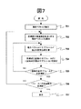
次に、上記の手順を図7のフローチャートに示す。先ず、ステップ701にて、上述の図5にて説明したように、前記中間フィールドBの画素を終点とし、前記前フィールドAの画素を始点とする動きベクトルFを前記中間フィールドBのそれぞれの画素について検出する。次にステップ702において、ステップ701において検出した動きベクトルのうち、対象となる一の画素を終点とする動きベクトルFを選出する。次に、ステップ703にて、これから再構成を行う対象フィールドの一の画素の一のサブフィールドについて、ステップ702で選出した動きベクトルFと対象サブフィールドの番号および前記αを用いて、例えば、数式4から取得する再設定前のサブフィールドの画素位置ベクトルを求める。次に、ステップ704にて、対象フィールドの再構成画素の対象サブフィールドに、求めた画素位置ベクトルの示す画素における同じ番号のサブフィールドの発光データを設定する。次に、ステップ705にて、当該一の画素の全てのサブフィールドについて再設定したか否かを判定する。全てのサブフィールドについて再設定していれば、ステップ706に進む。そうでなければ、残りのサブフィールドについて、ステップ703およびステップ704の処理をおこなう。次に、ステップ706においては、対象フィールドの全ての画素についてサブフィールドの再設定が完了したかを判定する。全ての画素についてサブフィールドの再設定が完了していれば、ステップ707に進む。そうでなければ、残りの画素について、ステップ702〜705の処理をおこなう。ステップ707では、ステップ706で得られた対象フィールドの表示データを表示する。
Next, the above procedure is shown in the flowchart of FIG. First, in
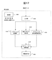
図16は、本発明の第3の実施例に係る表示装置の一例を示すブロック図である。図16の表示装置は、例えば、入力部1400、動きベクトルF検出部1610、サブフィールド変換部1420、サブフィールド再構成部1640、画像表示部1450、制御部1460を備えている。
FIG. 16 is a block diagram showing an example of a display device according to the third embodiment of the present invention. 16 includes, for example, an
まず、入力部1400には動画像データが入力される。例えば入力部は、TV放送用のチューナー、画像入力端子、ネットワーク接続端子などを備える。また、入力された動画像データに従来技術の変換処理等を行い、変換処理後の表示データを動きベクトルF検出部1610に対して出力する。サブフィールド変換部1420では、表示データをサブフィールドデータに変換する。動きベクトルF検出部1610では、上述の図5にて説明したように、前記中間フィールドBの画素を終点とし、前記前フィールドAの画素を始点とする動きベクトルFを前記中間フィールドBのそれぞれの画素について検出する。さらに、前記前フィールドAの画素を始点とし、前記中間フィールドBの一の画素を終点とする動きベクトルを動きベクトルFとして検出する。すなわち、図7のステップ701およびステップ702は、例えば動きベクトルF検出部1610で行われる。サブフィールド再構成部1640では、前記動きベクトルF検出部1610で検出した動きベクトルF、対象サブフィールドの番号および前記αなどをパラメータとして、数式4により、再構成対象のサブフィールドに再配置するための、再構成前のサブフィールドの画素位置を計算する。ここで、前記αの算出は、サブフィールド再構成部1640で行ってもよいが、1TVフィールド期間や、中間フィールドの1TVフィールドの先頭からの時間を予め記憶しているメモリ等から、制御部1460が取得して算出してよい。さらに、サブフィールド再構成部1640は、サブフィールド変換部1420が出力するサブフィールドデータの前記画素位置におけるサブフィールドの発光データを取得する。取得した発光データを再構成対象のサブフィールドに再配置する。これを繰り返すことにより、1画素毎にサブフィールドを再構成し、サブフィールド変換部1420で求めたサブフィールドデータを再構成し、対象フィールドのサブフィールドデータを新たに生成する。図7のステップ703、704および705は、例えば、サブフィールド再構成部1640で行われる。画像表示部1450は、点灯および消灯などの発光動作を行う複数の画素を有する。ここで、画像表示部1450は、前記サブフィールド再構成部1640で求めたサブフィールドデータに基づいて、各画素の点灯または消灯を制御し、画像を表示する。図7のステップ707は、例えば、画像表示部1450で行われる。また図16において、制御部1460は例えば、図16の表示装置の各要素に接続される。図16の表示装置の各要素の動作は、上述した通り、各構成要素の自律的な動作としても良いが、また、例えば制御部1460の指示により動作しても構わない。また、図7のステップ705、706などは、例えば、制御部1460が行ってもよい。
First, moving image data is input to the
以上説明した第3の実施例の表示方法によって、一つの対象フィールドを再構成して一つの新たなフィールドを作成することができる。これを対象フィールドを代えながら繰り返すことにより、新たな複数のフィールドを生成して画像を表示することができる。 By the display method of the third embodiment described above, one target field can be reconstructed and one new field can be created. By repeating this while changing the target field, it is possible to generate a plurality of new fields and display an image.
以上説明した第3の実施例によれば、動きベクトルによる視線パスを考慮したサブフィールド再構成が実現でき、動画ボヤケや動画擬似輪郭の発生を抑制できる。また、設定されないサブフィールドの発生を防止することができる。また、このサブフィールドの再構成を行う際の、サブフィールドの移動量を低減することができる。これにより、画像の揺れ等を抑制することができ、より自然な画像が得られるという効果がある。さらに、これらを回路処理量の低減とともに実現することが可能となる。 According to the third embodiment described above, subfield reconstruction can be realized in consideration of a line-of-sight path based on a motion vector, and generation of moving image blur and moving image pseudo contour can be suppressed. In addition, it is possible to prevent occurrence of subfields that are not set. Further, the amount of movement of the subfield can be reduced when the subfield is reconfigured. Thereby, it is possible to suppress the shaking of the image and the like, and there is an effect that a more natural image can be obtained. Furthermore, these can be realized with a reduction in circuit throughput.
次に、本発明の第4の実施例について説明する。 Next, a fourth embodiment of the present invention will be described.
本発明の第4の実施例は、本発明の第2の実施例に係る発光期間を考慮した当該発光開始時間の間隔を可変とする表示方法に対し、本発明の第3の実施例に係るサブフィールドの再構成の方法を取り入れたものである。 The fourth embodiment of the present invention is related to the third embodiment of the present invention in contrast to the display method in which the interval of the light emission start time in consideration of the light emission period according to the second embodiment of the present invention is variable. It incorporates the method of subfield reconstruction.
ここで、以下の説明では、第2の実施例と同様に、表示負荷が大きいとき、すなわち、均等間隔での各サブフィールドの発光開始時間より早くサブフィールドが発光し、視線パスの傾きが小さくなる場合を例として説明をする。 Here, in the following description, as in the second embodiment, when the display load is large, that is, the subfield emits light earlier than the light emission start time of each subfield at equal intervals, and the inclination of the line-of-sight path is small. An example will be described.
また、第3の実施例と同じく、サブフィールド再構成の対象フィールドは第3の実施例に示したの3つの方式のいずれを用いてもよい。よって、本実施例の以下の説明において単に「対象フィールド」として説明するが、この「対象フィールド」は図5の前フィールドA、中間フィールドB、現フィールドCのいずれであっても構わない。 As in the third embodiment, any of the three methods shown in the third embodiment may be used as the target field for subfield reconstruction. Therefore, in the following description of the present embodiment, description will be made simply as “target field”, but this “target field” may be any of the previous field A, intermediate field B, and current field C in FIG.
図8を用いて、本方法における対象フィールドのサブフィールドの再構成の例を説明する。図8は、横軸を画素の水平位置、縦軸を時間とし、サブフィールド数nが6の場合の表示データを表したものである。ここで、本実施例は第2の実施例と同じく発光期間を考慮した当該発光開始時間の間隔を可変とする表示方法を用いるものである。ここで、本図では1フィールドの表示期間(60Hz画像の場合、16.67ms)に対する1フィールドの先頭からの各サブフィールドの発光開始時間が、第2の実施例と同じく表1(2)に示すものとする。 An example of the reconstruction of the subfield of the target field in this method will be described with reference to FIG. FIG. 8 shows display data when the horizontal axis is the horizontal position of the pixel, the vertical axis is time, and the number of subfields n is six. Here, the present embodiment uses a display method in which the interval of the light emission start time in consideration of the light emission period is variable as in the second embodiment. Here, in this figure, the emission start time of each subfield from the head of one field for the display period of one field (16.67 ms in the case of a 60 Hz image) is shown in Table 1 (2) as in the second embodiment. Shall be shown.
ここで、図8において、対象フィールドの画素(n−1)の各サブフィールドの再構成について考える。 Here, in FIG. 8, the reconstruction of each subfield of the pixel (n−1) of the target field is considered.
まず、本実施例では、図5において、前フィールドAの画素を始点とし、中間フィールドBの画素(n−1)を通過し、現フィールドCの画素を終点とする動きベクトルにおいて、当該終点の画素を基準とした当該始点の画素の相対位置が水平方向に−6であるとする。また、このときの動きベクトルEのベクトル値は+6となる。ここで、図5における中間フィールドBが、前フィールドAと現フィールドCとの間の1TVフィールド期間の中心の位置にあるとする。このとき、中間フィールドBの画素(n−1)を終点とし、前フィールドAの画素を始点とする動きベクトルFにおいては、当該動きベクトルFの終点の画素(n−1)を基準とした、当該動きベクトルFの始点の相対位置は水平方向に−3となる。また、このときの動きベクトルFのべクトル値は+3となる。 First, in the present embodiment, in FIG. 5, in the motion vector having the pixel in the previous field A as the start point, passing through the pixel (n−1) in the intermediate field B and having the pixel in the current field C as the end point, Assume that the relative position of the pixel at the start point with respect to the pixel is −6 in the horizontal direction. At this time, the vector value of the motion vector E is +6. Here, it is assumed that intermediate field B in FIG. 5 is located at the center of one TV field period between previous field A and current field C. At this time, in the motion vector F starting from the pixel (n−1) in the intermediate field B and starting from the pixel in the previous field A, the pixel (n−1) at the end of the motion vector F is used as a reference. The relative position of the start point of the motion vector F is −3 in the horizontal direction. Further, the vector value of the motion vector F at this time is +3.
次に、取得する再構成前の各サブフィールドの画素位置を、例えば再構成対象の画素を基準として数式6により求める。
Next, the pixel position of each subfield before reconstruction to be acquired is obtained by, for example, Expression 6 using the pixel to be reconstructed as a reference.
ここで、各パラメータの定義は、他の実施例で用いる各数式と同じである。
Here, the definition of each parameter is the same as each mathematical expression used in the other embodiments.
本実施例では、前記前フィールドAの画素を始点とし前記中間フィールドBの画素を終点とする動きベクトルのうちから、再構成対象画素(n−1)を終点とする動きベクトルFを選出し、対象フィールドの画素(n−1)の各サブフィールドごとに数式6を用いて前記画素位置ベクトルの算出を行い、サブフィールドの再構成を行う。以下にこれを説明する。 In this embodiment, a motion vector F having the pixel to be reconstructed (n−1) as an end point is selected from motion vectors having the pixel in the previous field A as a start point and the pixel in the intermediate field B as an end point. The pixel position vector is calculated using Equation 6 for each subfield of the pixel (n−1) of the target field, and the subfield is reconstructed. This will be described below.
図8(b)の例においては、上述の通り、再構成対象の画素である画素(n―1)を終点とする動きベクトルFの始点の画素は、画素(n−1)を基準とした相対位置として水平方向に−3の位置にあり、当該動きベクトルFのベクトル値が+3である。ここで、数式6を用いることより、対象フィールドの画素(n−1)の各サブフィールドについて画素位置ベクトルXiを算出できる。画素位置ベクトルXiはそれぞれ、SF6が−1、SF5が0、SF4が0、SF3が+1、SF2が+1、SF1が+2となる。 In the example of FIG. 8B, as described above, the pixel at the start point of the motion vector F whose end point is the pixel (n-1) that is the pixel to be reconstructed is based on the pixel (n-1). The relative position is -3 in the horizontal direction, and the vector value of the motion vector F is +3. Here, by using Expression 6, it is possible to calculate the pixel position vector Xi for each subfield of the pixel (n−1) of the target field. The pixel position vectors Xi are −1 for SF6, 0 for SF5, 0 for SF4, +1 for SF3, +1 for SF2, and +2 for SF1, respectively.
従って、図8(b)の矢印804が示すように、SF6は画素(n−2)からサブフィールドの発光データを取得する。また、SF5とSF4はもとの画素(n−1)からサブフィールドの発光データを取得する。また、矢印803が示すように、SF3は画素nからサブフィールドの発光データを取得する。また、矢印802が示すように、SF2は画素nからサブフィールドの発光データを取得する。また、矢印801が示すように、SF1は画素(n+1)からサブフィールドの発光データを取得する。
Therefore, as indicated by the arrow 804 in FIG. 8B, the SF 6 acquires the light emission data of the subfield from the pixel (n−2). SF5 and SF4 obtain the light emission data of the subfield from the original pixel (n−1). In addition, as indicated by an
また、前記中間フィールドBの他の画素を終点とする動きベクトルFの始点の画素が、上記画素(n−1)と同じく、再構成対象画素を基準とした相対位置として水平方向に−3の位置にあり、いずれの動きベクトルFもベクトル値が+3である場合は、上記画素(n−1)と同様に、対象フィールドの再構成対象画素の各サブフィールドにつき、数式6を用いて画素位置ベクトルXiを算出し、求めた画素位置のサブフィールドにより、他の画素の各サブフィールドを再配置することができる。このとき、再構成後のサブフィールドは、図8(c)に示すようになる。このとき結果として、静止画において同一の画素に配置されていた複数のサブフィールド(図8において同一の模様で示されたサブフィールド)が、再構成後の対象フィールドでは視線パス上に並ぶ。 Further, the start pixel of the motion vector F whose end point is another pixel in the intermediate field B is −3 in the horizontal direction as a relative position with respect to the reconstruction target pixel as in the case of the pixel (n−1). If any of the motion vectors F has a vector value of +3, the pixel position is calculated using Equation 6 for each subfield of the reconstruction target pixel of the target field, similarly to the pixel (n−1). The vector Xi is calculated, and the subfields of other pixels can be rearranged according to the subfield of the obtained pixel position. At this time, the subfield after reconstruction is as shown in FIG. As a result, a plurality of subfields (subfields indicated by the same pattern in FIG. 8) arranged in the same pixel in the still image are arranged on the line-of-sight path in the target field after reconstruction.
よって、第4の実施例では、他の実施例と同じく、仮に静止画であるとするときに同一の画素に配置される複数のサブフィールドを視線パス上に並べることができる。このとき、本実施例では、第2の実施例と同じく動きベクトルとサブフィールドの発光間隔をパラメータとしてサブフィールドを再構成しているので、サブフィールドの発光間隔が可変である場合であっても、サブフィールドの発光パターンが、ユーザーが画像を見る際の視線パス上により好適に整列することになる。これにより動画ボヤケや動画擬似輪郭の発生を抑制できる。 Therefore, in the fourth embodiment, as in the other embodiments, a plurality of subfields arranged in the same pixel can be arranged on the line-of-sight path, assuming that the image is a still image. At this time, in this embodiment, as in the second embodiment, the subfield is reconfigured using the motion vector and the light emission interval of the subfield as parameters, so even if the light emission interval of the subfield is variable, The light emission patterns of the subfields are more preferably aligned on the line-of-sight path when the user views the image. Thereby, generation | occurrence | production of a moving image blur and a moving image pseudo contour can be suppressed.
また、本実施例では、第3の実施例と同じく、サブフィールドの発光データの再構成時において、再構成時のサブフィールドの発光データの移動量を低減することができる。これによりより自然な画像が得られるという効果がある。 Further, in this embodiment, similarly to the third embodiment, when the subfield light emission data is reconstructed, the amount of movement of the subfield light emission data at the time of reconstruction can be reduced. As a result, a more natural image can be obtained.
この手順を図9のフローチャートに示す。先ず、ステップ901にて、図7のステップ701と同様に動きベクトルFを前記中間フィールドBのそれぞれの画素について検出する。次に、ステップ902にて、図4のステップ402と同様に各サブフィールドの発光開始時間を算出する。次に、ステップ903にて、ステップ901において検出した動きベクトルのうち、対象となる一の画素を終点とする動きベクトルFを選出する。ここで、ステップ904にて、前記動きベクトルFと1TVフィールド期間に対する対象サブフィールドの発光開始時間、および前記αを用いて、例えば、数式6から取得する再設定前のサブフィールドの画素位置ベクトルを求める。次に、ステップ905にて、対象フィールドにおいて、再構成先の画素の対象サブフィールドに、求めた再設定前の画素位置ベクトルの示す画素における同じ番号のサブフィールドの発光データを設定する。次に、ステップ906、ステップ907においては、図7のステップ705、ステップ706と同様の判定処理、ループ処理を行う。また、ステップ908において、ステップ907で得られた対象フィールドの表示データを表示する。
This procedure is shown in the flowchart of FIG. First, in
図17は、本発明の第4の実施例に係る表示装置の一例を示すブロック図である。図17の表示装置は、例えば、入力部1400、動きベクトルF検出部1610、サブフィールド変換部1420、サブフィールド発光時間算出部1530、サブフィールド再構成部1740、画像表示部1450、制御部1460を備えている。入力部1400、サブフィールド変換部1420、画像表示部1450および制御部1460の動作については、第1の実施例と同様であるので説明を省略する。また、動きベクトルF検出部1610の動作についても、第3の実施例と同様であるので説明を省略する。ここで、サブフィールド再構成部1740は、動きベクトルF検出部1610が検出した動きベクトルF、前記サブフィールド発光時間算出部1530で求めた各サブフィールドの発光開始時間、1TVフィールド期間および前記αなどをパラメータとして、数式6により、再構成対象のサブフィールドに再配置するための、再構成前のサブフィールドの画素位置を計算する。ここで、前記αの算出は、サブフィールド再構成部1740で行ってもよいが、1TVフィールド期間や、各サブフィールドの発光開始時間を予め記憶しているメモリ等から、制御部1460が取得して算出してもよい。さらに、サブフィールド再構成部1740は、サブフィールド変換部1420から出力されるサブフィールドデータの前記画素位置におけるサブフィールドの発光データを取得する。取得した発光データを再構成対象のサブフィールドに再配置する。これを繰り返すことにより、1画素毎にサブフィールドを再構成し、サブフィールド変換部1420で求めたサブフィールドデータを再構成し、対象フィールドのサブフィールドデータを新たに生成する。図9のステップ904、905および906は、例えば、サブフィールド再構成部1740で行われる。以上説明した各部の動作により取得したサブフィールドデータは、他の実施例と同じく画像表示部1450において表示される。また図17において、制御部1460は例えば、図17の表示装置の各要素に接続される。図17の表示装置の各要素の動作は、上述した通り、各構成要素の自律的な動作としても良いが、また、例えば制御部1460の指示により動作しても構わない。また、図9のステップ906、907などは、例えば、制御部1460が行ってもよい。
FIG. 17 is a block diagram showing an example of a display device according to the fourth embodiment of the present invention. 17 includes, for example, an
以上説明した第4の実施例の表示方法によって、一つの対象フィールドを再構成して一つの新たなフィールドを作成することができる。これを対象フィールドを代えながら繰り返すことにより、新たな複数のフィールドを生成して画像を表示することができる。 According to the display method of the fourth embodiment described above, one target field can be reconstructed to create one new field. By repeating this while changing the target field, it is possible to generate a plurality of new fields and display an image.
以上説明した第4の実施例によれば、視線パスを考慮して発光サブフィールドの配置をしながら、全画素の全サブフィールドが再設定される。これにより、動画ボヤケや動画擬似輪郭の発生を抑制しながら、サブフィールドの未配置を防止することができる。また、画像の表示負荷率などに応じて各サブフィールドの発光開始時間を可変とする表示方法においても、ユーザーの視線が発光するサブフィールド上をより好適にトレースするように、サブフィールドの再構成が実現できる。また、これらをより少ない演算量で実現することができる。さらに、このサブフィールドを再構成を行う際の、サブフィールドの移動量を低減し、画像の揺れ等を抑制することができる。これにより、より自然な画像が得られるという効果がある。 According to the fourth embodiment described above, all subfields of all pixels are reset while arranging the light emission subfields in consideration of the line-of-sight path. Thereby, it is possible to prevent subfields from being unallocated while suppressing the occurrence of moving image blur and moving image pseudo contour. In addition, in the display method in which the light emission start time of each subfield is variable according to the display load factor of the image, the subfield is reconfigured so that the user's line of sight can be traced more appropriately on the subfield. Can be realized. Also, these can be realized with a smaller amount of calculation. Furthermore, when the subfield is reconstructed, the amount of movement of the subfield can be reduced, and image shaking or the like can be suppressed. Thereby, there is an effect that a more natural image can be obtained.
上記の例では、均等間隔での各サブフィールドの発光開始時間より早くサブフィールドが発光する例について説明をしたが、遅くサブフィールドが発光し、視線パスの傾きが大きくなる場合であっても、数式6を用いたサブフィールドの再構成を行うことにより、同様の効果が得られる。 In the above example, the example in which the subfield emits light earlier than the light emission start time of each subfield at equal intervals has been described, but even when the subfield emits light late and the line-of-sight path slope increases, A similar effect can be obtained by reconstructing the subfield using Equation (6).
また、本発明の第3の実施例もしくは第4の実施例において、中間フィールドBが前後のフィールドの中間点に配置される場合を例に説明したが、前後のフィールド間の中間点以外に位置する中間フィールドの場合であっても同様の効果が得られる。 Further, in the third or fourth embodiment of the present invention, the case where the intermediate field B is arranged at the intermediate point between the preceding and following fields has been described as an example. Even in the case of an intermediate field, the same effect can be obtained.
また、本発明の各実施例において、実施例サブフィールドの発光位置として、サブフィールドの発光開始時間を例として説明をしたが、これは、サブフィールドの発光を示す時間パラメータの一例であり、サブフィールドの発光開始時間以外のパラメータを用いてもよい。例えば、サブフィールドの発光開始から発光終了までの間の発光期間の長さをパラメータとしてもよい。 In each embodiment of the present invention, the light emission start time of the subfield has been described as an example of the light emission position of the subfield. This is an example of a time parameter indicating the light emission of the subfield. Parameters other than the field emission start time may be used. For example, the length of the light emission period from the light emission start to the light emission end of the subfield may be used as a parameter.
また、本発明の各実施例において、動きベクトルVやVfに関して、例として水平方向の移動のみに係る1次元の値を用いて説明したが、2次元の値であっても同様の効果が得られる。 In each embodiment of the present invention, the motion vectors V and Vf have been described using one-dimensional values related only to horizontal movement as an example, but similar effects can be obtained even with two-dimensional values. It is done.
また、本発明の各実施例において、いずれもサブフィールド数が6の場合について説明したが、サブフィールド数が6以外の場合についても同様の効果が得られる。 In each of the embodiments of the present invention, the case where the number of subfields is 6 has been described. However, the same effect can be obtained when the number of subfields is other than 6.
なお、以上説明した4つの実施例はそれぞれの有利な効果を有する。例えば、第1の実施例は、画質の劣化の防止をしつつ、その演算処理量を低減するという効果を有する。また、例えば、第2の実施例は、動画ボヤケや動画擬似輪郭の発生をより好適に抑制できる効果を有する。例えば、第3の実施例は、画像の揺れ等を抑制することができ、より自然な画像が得られるという効果を有する。また、その演算処理量を低減することができる。例えば、第4の実施例は、動画ボヤケや動画擬似輪郭の発生をより好適に抑制し、さらに画像の揺れ等を抑制することができる効果を合わせて有する。 The four embodiments described above have their respective advantageous effects. For example, the first embodiment has an effect of reducing the amount of calculation processing while preventing deterioration of image quality. Further, for example, the second embodiment has an effect that the generation of moving image blur and moving image pseudo contour can be more preferably suppressed. For example, the third embodiment has an effect that image fluctuations can be suppressed and a more natural image can be obtained. In addition, the amount of calculation processing can be reduced. For example, the fourth embodiment has an effect that it is possible to more appropriately suppress the occurrence of moving image blur and moving image pseudo contour, and to further suppress the shaking of the image.
なお、以上説明した各図、各方法等の実施例のいずれを組み合わせても、本発明の一実
施の形態となりうる。
It should be noted that any one of the embodiments described above, such as each drawing and each method, can be combined into one embodiment of the present invention.
以上説明した本発明の各実施例によれば、より好適に画質の劣化を防止することが可能となる。 According to each of the embodiments of the present invention described above, it is possible to more suitably prevent image quality deterioration.
1400…入力部、1410…動きベクトル検出部、1420…サブフィールド変換部、1440…サブフィールド再構成部、1450…画像表示部、1460…制御部、1530…サブフィールド発光時間算出部、1540…サブフィールド再構成部、1610…動きベクトルF検出部、1640…サブフィールド再構成部、1740…サブフィールド再構成部、
DESCRIPTION OF
Claims (14)
動画像を入力する入力部と、
前記入力部に入力された動画像に含まれる複数のフィールドもしくは前記複数のフィールドから生成されるフィールドのうち、一のフィールドの画素を始点とし他の一のフィールドの画素を終点とする動きベクトルを検出する動きベクトル検出部と、
前記入力部に入力された動画像をサブフィールドの発光データに変換するサブフィールド変換部と、
前記サブフィールド変換部から出力されるサブフィールドの発光データを、前記動きベクトル検出部が検出した動きベクトルを用いた演算処理によって再構成するサブフィールド再構成部と、
前記サブフィールド再構成部から出力されるサブフィールドの発光データを用いて、画像を表示する表示部とを備え、
前記動きベクトル検出部は、前記入力部に入力された動画像に含まれる第1のフィールドよりも時間的に前に配置され、前記入力部に入力された動画像に含まれる第2のフィールドの画素を始点とし、前記第1のフィールドの画素を終点とする動きベクトルを検出し、
前記サブフィールド再構成部は、前記第1のフィールドの前記再構成対象画素について、前記第1のフィールドと前記第2のフィールドの間の1TVフィールド期間がTfであって、前記1TVフィールド期間の始期からi番目のサブフィールドの発光開始までの時間がSiであり、i番目のサブフィールドについて再構成する場合に、前記検出した動きベクトルのうち、前記第2のフィールドの画素を始点とし、前記第1のフィールドの前記再構成対象画素を終点とする動きベクトルを選択し、前記選択した動きベクトルに、−Si/Tfを乗じて前記位置ベクトルを得、
前記各サブフィールドの発行開始時間の間隔が、映像の輝度に関するパラメータに応じて変化することを特徴とする画像表示装置。 In an image display device that divides one field period in an input moving image into a plurality of subfield periods and controls whether or not lighting is performed in each of the plurality of subfield periods.
An input unit for inputting a moving image;
Of a plurality of fields included in the moving image input to the input unit or a field generated from the plurality of fields, a motion vector having a pixel in one field as a start point and a pixel in another field as an end point A motion vector detection unit to detect;
A subfield conversion unit that converts the moving image input to the input unit into light emission data of a subfield;
A subfield reconstruction unit that reconstructs the light emission data of the subfield output from the subfield conversion unit by arithmetic processing using a motion vector detected by the motion vector detection unit;
A display unit for displaying an image using the light emission data of the subfield output from the subfield reconstruction unit;
The motion vector detection unit is arranged temporally before the first field included in the moving image input to the input unit, and includes a second field included in the moving image input to the input unit. Detecting a motion vector starting from a pixel and ending at a pixel in the first field;
The sub-field reconstruction unit has a TTV field period between the first field and the second field for the reconstruction target pixel of the first field, and Tf is a start period of the 1TV field period The time from the start of light emission to the i-th subfield is Si, and when reconfiguration is performed for the i-th subfield, the pixel of the second field among the detected motion vectors is used as a starting point, and the first Selecting a motion vector whose end point is the pixel to be reconstructed in one field, multiplying the selected motion vector by -Si / Tf to obtain the position vector;
The spacing of the issuance start time for each sub-field, the image display device comprising that you change depending on parameters related to the brightness of the image.
動画像を入力する入力部と、
前記入力部に入力された動画像に含まれる複数のフィールドもしくは前記複数のフィールドから生成されるフィールドのうち、一のフィールドの画素を始点とし他の一のフィールドの画素を終点とする動きベクトルを検出する動きベクトル検出部と、
前記入力部に入力された動画像をサブフィールドの発光データに変換するサブフィールド変換部と、
前記サブフィールド変換部から出力されるサブフィールドの発光データを、前記動きベクトル検出部が検出した動きベクトルを用いた演算処理によって再構成するサブフィールド再構成部と、
前記サブフィールド再構成部から出力されるサブフィールドの発光データを用いて、画像を表示する表示部とを備え、
前記動きベクトル検出部は、前記入力部に入力された動画像に含まれる第1のフィールドと、前記第1のフィールドよりも時間的に前に配置され前記入力部に入力された動画像に含まれる第2のフィールドとの間に配置される第3のフィールドの画素を終点とし、前記第2のフィールドの画素を始点とする動きベクトルを検出し、
前記サブフィールド再構成部は、前記第3のフィールドもしくは前記第1のフィールドもしくは前記第2のフィールドの前記再構成対象画素のN個のサブフィールドのうち、i番目のサブフィールドについて再構成する場合に、前記検出した動きベクトルのうち、前記第2のフィールドの画素を始点とし前記第3のフィールドの前記再構成対象画素を終点とする動きベクトルを選択し、前記第2のフィールドと前記第1のフィールドとの間の期間に対する前記第2のフィールドと前記第3のフィールドとの間の期間の比である値αを用いて、前記選択した動きベクトルに、−((i−1)−(N×α))/(N×α)を乗じて前記位置ベクトルを得ることを特徴とする画像表示装置。 In an image display device that divides one field period in an input moving image into a plurality of subfield periods and controls whether or not lighting is performed in each of the plurality of subfield periods.
An input unit for inputting a moving image;
Of a plurality of fields included in the moving image input to the input unit or a field generated from the plurality of fields, a motion vector having a pixel in one field as a start point and a pixel in another field as an end point A motion vector detection unit to detect;
A subfield conversion unit that converts the moving image input to the input unit into light emission data of a subfield;
A subfield reconstruction unit that reconstructs the light emission data of the subfield output from the subfield conversion unit by arithmetic processing using a motion vector detected by the motion vector detection unit;
A display unit for displaying an image using the light emission data of the subfield output from the subfield reconstruction unit;
The motion vector detection unit is included in a first field included in the moving image input to the input unit, and a moving image input before the first field and disposed in the input unit. Detecting a motion vector having a third field pixel arranged between the second field and the second field as an end point, and a pixel in the second field as a start point;
The subfield reconstruction unit reconstructs an i-th subfield among N subfields of the reconstruction target pixel of the third field, the first field, or the second field. Then, from the detected motion vectors, a motion vector starting from a pixel in the second field and ending in the reconstruction target pixel in the third field is selected, and the second field and the first field are selected. Using the value α, which is the ratio of the period between the second field and the third field to the period between the second field and the third field,-((i-1)-( N × α)) / (N × α) to obtain the position vector.
動画像を入力する入力部と、
前記入力部に入力された動画像に含まれる複数のフィールドもしくは前記複数のフィールドから生成されるフィールドのうち、一のフィールドの画素を始点とし他の一のフィールドの画素を終点とする動きベクトルを検出する動きベクトル検出部と、
前記入力部に入力された動画像をサブフィールドの発光データに変換するサブフィールド変換部と、
前記サブフィールド変換部から出力されるサブフィールドの発光データを、前記動きベクトル検出部が検出した動きベクトルを用いた演算処理によって再構成するサブフィールド再構成部と、
前記サブフィールド再構成部から出力されるサブフィールドの発光データを用いて、画像を表示する表示部とを備え、
前記動きベクトル検出部は、前記入力部に入力された動画像に含まれる第1のフィールドと、前記第1のフィールドよりも時間的に前に配置され前記入力部に入力された動画像に含まれる第2のフィールドとの間に配置される第3のフィールドの画素を終点とし、前記第2のフィールドの画素を始点とする動きベクトルを検出し、
前記サブフィールド再構成部は、前記第3のフィールドもしくは前記第1のフィールドもしくは前記第2のフィールドの前記再構成対象画素について、前記第1のフィールドと前記第2のフィールドの間の1TVフィールド期間がTfであって、前記1TVフィールド期間の始期からi番目のサブフィールドの発光開始までの時間がSiであり、前記i番目のサブフィールドについて再構成する場合に、前記検出した動きベクトルのうち、前記第2のフィールドの画素を始点とし前記第3のフィールドの前記再構成対象画素を終点とする動きベクトルを選択し、前記第2のフィールドと前記第1のフィールドとの間の期間に対する前記第2のフィールドと前記第3のフィールドとの間の期間の比である値αを用いて、前記選択した動きベクトルに、−(Si−(Tf×α))/(Tf×α)を乗じて前記位置ベクトルを得ることを特徴とする画像表示装置。 In an image display device that divides one field period in an input moving image into a plurality of subfield periods and controls whether or not lighting is performed in each of the plurality of subfield periods.
An input unit for inputting a moving image;
Of a plurality of fields included in the moving image input to the input unit or a field generated from the plurality of fields, a motion vector having a pixel in one field as a start point and a pixel in another field as an end point A motion vector detection unit to detect;
A subfield conversion unit that converts the moving image input to the input unit into light emission data of a subfield;
A subfield reconstruction unit that reconstructs the light emission data of the subfield output from the subfield conversion unit by arithmetic processing using a motion vector detected by the motion vector detection unit;
A display unit for displaying an image using the light emission data of the subfield output from the subfield reconstruction unit;
The motion vector detection unit is included in a first field included in the moving image input to the input unit, and a moving image input before the first field and disposed in the input unit. Detecting a motion vector having a third field pixel arranged between the second field and the second field as an end point, and a pixel in the second field as a start point;
The sub-field reconstruction unit, said for the reconstruction pixel of the third field or the first field or the second field, 1TV field between the second field and the first field When the period is Tf, the time from the start of the 1TV field period to the start of light emission of the i-th subfield is Si, and when the i-th subfield is reconstructed, , Selecting a motion vector starting from the pixel in the second field and ending in the pixel to be reconstructed in the third field, and for the period between the second field and the first field Using the value α, which is the ratio of the period between the second field and the third field, the selected motion vector A, - (Si- (Tf × α )) / image display apparatus characterized by (Tf × alpha) is multiplied by obtaining the position vector.
前記各サブフィールドの発光開始時間の間隔が、均等間隔であることを特徴とする画像表示装置。 An image display device according to claim 2,
The distance of the light emission start time for each sub-field, the image display device comprising equally spaced der Rukoto.
前記各サブフィールドの発光開始時間の間隔が、映像の輝度に関するパラメータに応じて変化することを特徴とする画像表示装置。 An image display device according to claim 3,
The image display device characterized in that the interval between the light emission start times of the subfields changes according to a parameter relating to the luminance of the video .
前記動きベクトル検出部による前記第2のフィールドの画素を始点とし前記第1のフィールドの画素を終点とする動きベクトルの検出と、前記サブフィールド再構成部による前記再構成対象画素ごとのサブフィールドの再構成とを、前記第1のフィールドのすべての画素について行い、前記第1のフィールドを構成する各サブフィールドの発光データを再構成することを特徴とする画像表示装置。 An image display device according to claim 2 ,
Detection of a motion vector starting from a pixel in the second field and ending in a pixel in the first field by the motion vector detection unit, and subfields for each of the reconstruction target pixels by the subfield reconstruction unit and reconstruction is performed for all pixels of the first field, the image display device comprising that you reconstruct the emission data of each sub-field included in the first field.
前記動きベクトル検出部は、前記第3のフィールドのすべての画素について、前記第2のフィールドの画素を始点とし前記第3のフィールドの画素を終点とする動きベクトルの検出を行い、
前記サブフィールド再構成部は、前記第3のフィールドもしくは前記第1のフィールドもしくは前記第2のフィールドのいずれか一のフィールドのすべての画素について、前記検出した動きベクトルを用いて、サブフィールドの再構成を行うことを特徴とする画像表示装置。 An image display device according to claim 2 or claim 3, wherein
The motion vector detection unit detects , for all pixels in the third field, a motion vector having a pixel in the second field as a start point and a pixel in the third field as an end point;
The subfield reconstruction unit reconstructs a subfield by using the detected motion vector for all the pixels in the third field, the first field, or the second field. An image display device comprising: a configuration.
動画像を入力する入力ステップと、
前記入力ステップにおいて入力された動画像に含まれる複数のフィールドもしくは前記複数のフィールドから生成されるフィールドのうち、一のフィールドの画素を始点とし他の一のフィールドの画素を終点とする動きベクトルを検出する動きベクトル検出ステップと、
前記入力ステップにおいて入力された動画像をサブフィールドの発光データに変換するサブフィールド変換ステップと、
前記サブフィールド変換ステップから出力されるサブフィールドの発光データを、前記動きベクトル検出ステップにおいて検出した動きベクトルを用いた演算処理によって再構成するサブフィールド再構成ステップと、
前記サブフィールド再構成ステップから出力されるサブフィールドの発光データを用いて、画像を表示する表示ステップとを備え、
前記動きベクトル検出ステップは、前記入力ステップにおいて入力された動画像に含まれる第1のフィールドよりも時間的に前に配置され、前記入力ステップにおいて入力された動画像に含まれる第2のフィールドの画素を始点とし、前記第1のフィールドの画素を終点とする動きベクトルを検出し、
前記サブフィールド再構成ステップは、前記第1のフィールドの前記再構成対象画素について、前記第1のフィールドと前記第2のフィールドの間の1TVフィールド期間がTfであって、前記1TVフィールド期間の始期からi番目のサブフィールドの発光開始までの時間がSiであり、i番目のサブフィールドについて再構成する場合に、前記検出した動きベクトルのうち、前記第2のフィールドの画素を始点とし、前記第1のフィールドの前記再構成対象画素を終点とする動きベクトルを選択し、前記選択した動きベクトルに、−Si/Tfを乗じて前記位置ベクトルを得、
前記各サブフィールドの発光開始時間の間隔が、映像の輝度に関するパラメータに応じて変化することを特徴とする画像表示方法。 In an image display method for dividing one field period in an input moving image into a plurality of subfield periods, and controlling the presence or absence of lighting in each of the plurality of subfield periods,
An input step for inputting a moving image;
Among a plurality of fields included in the moving image input in the input step or a field generated from the plurality of fields, a motion vector having a pixel in one field as a start point and a pixel in another field as an end point A motion vector detection step to detect;
A subfield conversion step of converting the moving image input in the input step into light emission data of a subfield;
A subfield reconstruction step of reconstructing the light emission data of the subfield output from the subfield conversion step by a calculation process using the motion vector detected in the motion vector detection step;
A display step of displaying an image using the light emission data of the subfield output from the subfield reconstruction step,
The motion vector detection step is arranged temporally before the first field included in the moving image input in the input step, and the second field included in the moving image input in the input step. Detecting a motion vector starting from a pixel and ending at a pixel in the first field;
In the subfield reconstruction step, for the reconstruction target pixel in the first field, a 1TV field period between the first field and the second field is Tf, and the start of the 1TV field period The time from the start of light emission to the i-th subfield is Si, and when reconfiguration is performed for the i-th subfield, the pixel of the second field among the detected motion vectors is used as a starting point, and the first Selecting a motion vector whose end point is the pixel to be reconstructed in one field, multiplying the selected motion vector by -Si / Tf to obtain the position vector;
An image display method, wherein an interval between light emission start times of the subfields changes in accordance with a parameter relating to luminance of an image.
動画像を入力する入力ステップと、
前記入力ステップにおいて入力された動画像に含まれる複数のフィールドもしくは前記複数のフィールドから生成されるフィールドのうち、一のフィールドの画素を始点とし他の一のフィールドの画素を終点とする動きベクトルを検出する動きベクトル検出ステップと、
前記入力ステップにおいて入力された動画像をサブフィールドの発光データに変換するサブフィールド変換ステップと、
前記サブフィールド変換ステップから出力されるサブフィールドの発光データを、前記動きベクトル検出ステップにおいて検出した動きベクトルを用いた演算処理によって再構成するサブフィールド再構成ステップと、
前記サブフィールド再構成ステップから出力されるサブフィールドの発光データを用いて、画像を表示する表示ステップとを備え、
前記動きベクトル検出ステップは、前記入力ステップにおいて入力された動画像に含まれる第1のフィールドと、前記第1のフィールドよりも時間的に前に配置され前記入力ステップにおいて入力された動画像に含まれる第2のフィールドとの間に配置される第3のフィールドの画素を終点とし、前記第2のフィールドの画素を始点とする動きベクトルを検出し、
前記サブフィールド再構成ステップは、前記第3のフィールドもしくは前記第1のフィールドもしくは前記第2のフィールドの前記再構成対象画素のN個のサブフィールドのうち、i番目のサブフィールドについて再構成する場合に、前記検出した動きベクトルのうち、前記第2のフィールドの画素を始点とし前記第3のフィールドの前記再構成対象画素を終点とする動きベクトルを選択し、前記第2のフィールドと前記第1のフィールドとの間の期間に対する前記第2のフィールドと前記第3のフィールドとの間の期間の比である値αを用いて、前記選択した動きベクトルに、−((i−1)−(N×α))/(N×α)を乗じて前記位置ベクトルを得ることを特徴とする画像表示方法。 In an image display method for dividing one field period in an input moving image into a plurality of subfield periods, and controlling the presence or absence of lighting in each of the plurality of subfield periods,
An input step for inputting a moving image;
Among a plurality of fields included in the moving image input in the input step or a field generated from the plurality of fields, a motion vector having a pixel in one field as a start point and a pixel in another field as an end point A motion vector detection step to detect;
A subfield conversion step of converting the moving image input in the input step into light emission data of a subfield;
A subfield reconstruction step of reconstructing the light emission data of the subfield output from the subfield conversion step by a calculation process using the motion vector detected in the motion vector detection step;
A display step of displaying an image using the light emission data of the subfield output from the subfield reconstruction step,
The motion vector detection step includes a first field included in the moving image input in the input step, and a moving image input in the input step that is arranged temporally before the first field. Detecting a motion vector having a third field pixel arranged between the second field and the second field as an end point, and a pixel in the second field as a start point ;
In the subfield reconstruction step , the i-th subfield is reconstructed among N subfields of the reconstruction target pixel in the third field, the first field, or the second field. Then, from the detected motion vectors, a motion vector starting from a pixel in the second field and ending in the reconstruction target pixel in the third field is selected, and the second field and the first field are selected. Using the value α, which is the ratio of the period between the second field and the third field to the period between the second field and the third field,-((i-1)-( N × α)) / (N × α) to obtain the position vector.
動画像を入力する入力ステップと、
前記入力ステップにおいて入力された動画像に含まれる複数のフィールドもしくは前記複数のフィールドから生成されるフィールドのうち、一のフィールドの画素を始点とし他の一のフィールドの画素を終点とする動きベクトルを検出する動きベクトル検出ステップと、
前記入力ステップにおいて入力された動画像をサブフィールドの発光データに変換するサブフィールド変換ステップと、
前記サブフィールド変換ステップから出力されるサブフィールドの発光データを、前記動きベクトル検出ステップにおいて検出した動きベクトルを用いた演算処理によって再構成するサブフィールド再構成ステップと、
前記サブフィールド再構成ステップから出力されるサブフィールドの発光データを用いて、画像を表示する表示ステップとを備え、
前記動きベクトル検出ステップは、前記入力ステップにおいて入力された動画像に含まれる第1のフィールドと、前記第1のフィールドよりも時間的に前に配置され前記入力ステップにおいて入力された動画像に含まれる第2のフィールドとの間に配置される第3のフィールドの画素を終点とし、前記第2のフィールドの画素を始点とする動きベクトルを検出し、
前記サブフィールド再構成ステップは、前記第3のフィールドもしくは前記第1のフィールドもしくは前記第2のフィールドの前記再構成対象画素について、前記第1のフィールドと前記第2のフィールドの間の1TVフィールド期間がTfであって、前記1TVフィールド期間の始期からi番目のサブフィールドの発光開始までの時間がSiであり、前記i番目のサブフィールドについて再構成する場合に、前記検出した動きベクトルのうち、前記第2のフィールドの画素を始点とし前記第3のフィールドの前記再構成対象画素を終点とする動きベクトルを選択し、前記第2のフィールドと前記第1のフィールドとの間の期間に対する前記第2のフィールドと前記第3のフィールドとの間の期間の比である値αを用いて、前記選択した動きベクトルに、−(Si−(Tf×α))/(Tf×α)を乗じて前記位置ベクトルを得ることを特徴とする画像表示方法。 In an image display method for dividing one field period in an input moving image into a plurality of subfield periods, and controlling the presence or absence of lighting in each of the plurality of subfield periods,
An input step for inputting a moving image;
Among a plurality of fields included in the moving image input in the input step or a field generated from the plurality of fields, a motion vector having a pixel in one field as a start point and a pixel in another field as an end point A motion vector detection step to detect;
A subfield conversion step of converting the moving image input in the input step into light emission data of a subfield;
A subfield reconstruction step of reconstructing the light emission data of the subfield output from the subfield conversion step by a calculation process using the motion vector detected in the motion vector detection step;
A display step of displaying an image using the light emission data of the subfield output from the subfield reconstruction step,
The motion vector detection step includes a first field included in the moving image input in the input step, and a moving image input in the input step that is arranged temporally before the first field. Detecting a motion vector having a third field pixel arranged between the second field and the second field as an end point, and a pixel in the second field as a start point ;
In the subfield reconstruction step, a 1 TV field period between the first field and the second field for the reconstruction target pixel in the third field, the first field, or the second field. Is Tf, and the time from the start of the 1TV field period to the start of light emission of the i-th subfield is Si, and when reconfiguring the i-th subfield, A motion vector starting from a pixel in the second field and ending in the pixel to be reconstructed in the third field is selected, and the motion vector for the period between the second field and the first field is selected. Using the value α, which is the ratio of the period between two fields and the third field, The vector, - (Si- (Tf × α )) / image display method (Tf × alpha) is multiplied by, characterized in that obtaining the position vector.
前記各サブフィールドの発光開始時間の間隔が、均等間隔であることを特徴とする画像表示方法。 An image display method according to claim 9, wherein
The image display method according to claim 1 , wherein the intervals between the light emission start times of the subfields are equal .
前記各サブフィールドの発光開始時間の間隔が、映像の輝度に関するパラメータに応じて変化することを特徴とする画像表示方法。 An image display method according to claim 10,
An image display method, wherein an interval between light emission start times of the subfields changes in accordance with a parameter relating to luminance of an image.
前記動きベクトル検出ステップによる前記第2のフィールドの画素を始点とし前記第1のフィールドの画素を終点とする動きベクトルの検出と、前記サブフィールド再構成ステップによる前記再構成対象画素ごとのサブフィールドの再構成とを、前記第1のフィールドのすべての画素について行い、前記第1のフィールドを構成する各サブフィールドの発光データを再構成することを特徴とする画像表示方法。 An image display method according to claim 8 , comprising:
Detection of a motion vector starting from a pixel in the second field and ending in a pixel of the first field by the motion vector detection step, and subfields for each of the reconstruction target pixels by the subfield reconstruction step and reconstruction, the performed for all the pixels in the first field, the image display method comprising that you reconstruct the emission data of each sub-field included in the first field.
前記動きベクトル検出ステップは、前記第3のフィールドのすべての画素について、前記第2のフィールドの画素を始点とし前記第3のフィールドの画素を終点とする動きベクトルの検出を行い、
前記サブフィールド再構成ステップは、前記第3のフィールドもしくは前記第1のフィールドもしくは前記第2のフィールドのいずれか一のフィールドのすべての画素について、前記検出した動きベクトルを用いて、サブフィールドの再構成を行うことを特徴とする画像表示方法。 The image display method according to claim 9 or 10 , wherein:
The motion vector detection step detects, for all the pixels in the third field, a motion vector having a pixel in the second field as a start point and a pixel in the third field as an end point,
In the subfield reconstruction step, subfield reconstruction is performed using the detected motion vector for all the pixels of the third field, the first field, or the second field. An image display method characterized by performing configuration .
Priority Applications (3)
| Application Number | Priority Date | Filing Date | Title |
|---|---|---|---|
| JP2007046388A JP5141043B2 (en) | 2007-02-27 | 2007-02-27 | Image display device and image display method |
| KR20070118103A KR100931109B1 (en) | 2007-02-27 | 2007-11-19 | Image display device and image display method |
| US12/021,423 US8170106B2 (en) | 2007-02-27 | 2008-01-29 | Video displaying apparatus and video displaying method |
Applications Claiming Priority (1)
| Application Number | Priority Date | Filing Date | Title |
|---|---|---|---|
| JP2007046388A JP5141043B2 (en) | 2007-02-27 | 2007-02-27 | Image display device and image display method |
Publications (2)
| Publication Number | Publication Date |
|---|---|
| JP2008209671A JP2008209671A (en) | 2008-09-11 |
| JP5141043B2 true JP5141043B2 (en) | 2013-02-13 |
Family
ID=39715431
Family Applications (1)
| Application Number | Title | Priority Date | Filing Date |
|---|---|---|---|
| JP2007046388A Active JP5141043B2 (en) | 2007-02-27 | 2007-02-27 | Image display device and image display method |
Country Status (3)
| Country | Link |
|---|---|
| US (1) | US8170106B2 (en) |
| JP (1) | JP5141043B2 (en) |
| KR (1) | KR100931109B1 (en) |
Families Citing this family (9)
| Publication number | Priority date | Publication date | Assignee | Title |
|---|---|---|---|---|
| CN101803362A (en) * | 2007-09-10 | 2010-08-11 | Nxp股份有限公司 | Method and apparatus for motion estimation and motion compensation in video image data |
| JP2010078987A (en) * | 2008-09-26 | 2010-04-08 | Hitachi Ltd | Image display and image display method |
| WO2010037515A1 (en) | 2008-10-01 | 2010-04-08 | Bayer Materialscience Ag | Media for volume-holographic recording based on self-developing polymer |
| JP2010134046A (en) * | 2008-12-02 | 2010-06-17 | Tohoku Univ | Image display device and image display method |
| US20110228169A1 (en) * | 2008-12-24 | 2011-09-22 | Shinya Kiuchi | Video processing apparatus and video display apparatus |
| US20110273449A1 (en) | 2008-12-26 | 2011-11-10 | Shinya Kiuchi | Video processing apparatus and video display apparatus |
| WO2010089956A1 (en) | 2009-02-04 | 2010-08-12 | パナソニック株式会社 | Image processing apparatus and image display apparatus |
| US8947350B2 (en) * | 2009-09-14 | 2015-02-03 | Broadcom Corporation | System and method for generating screen pointing information in a television control device |
| WO2011086877A1 (en) * | 2010-01-13 | 2011-07-21 | パナソニック株式会社 | Video processing device and video display device |
Family Cites Families (20)
| Publication number | Priority date | Publication date | Assignee | Title |
|---|---|---|---|---|
| JP3711378B2 (en) * | 1995-02-06 | 2005-11-02 | 株式会社日立製作所 | Halftone display method and halftone display device |
| WO1998044479A1 (en) * | 1997-03-31 | 1998-10-08 | Matsushita Electric Industrial Co., Ltd. | Dynamic image display method and device therefor |
| JP3758294B2 (en) * | 1997-04-10 | 2006-03-22 | 株式会社富士通ゼネラル | Moving picture correction method and moving picture correction circuit for display device |
| EP0978817A1 (en) * | 1998-08-07 | 2000-02-09 | Deutsche Thomson-Brandt Gmbh | Method and apparatus for processing video pictures, especially for false contour effect compensation |
| EP0978816B1 (en) * | 1998-08-07 | 2002-02-13 | Deutsche Thomson-Brandt Gmbh | Method and apparatus for processing video pictures, especially for false contour effect compensation |
| JP2000089711A (en) * | 1998-09-16 | 2000-03-31 | Matsushita Electric Ind Co Ltd | Medium contrast display method of display device |
| KR100289534B1 (en) * | 1998-09-16 | 2001-05-02 | 김순택 | A method for displaying gray scale of PDP and an apparatus for the same |
| JP2000163013A (en) * | 1998-11-30 | 2000-06-16 | Matsushita Electric Ind Co Ltd | Halftone display method for display device |
| JP2000163004A (en) * | 1998-11-30 | 2000-06-16 | Matsushita Electric Ind Co Ltd | Halftone display method for display device |
| US7023450B1 (en) * | 1999-09-29 | 2006-04-04 | Thomson Licensing | Data processing method and apparatus for a display device |
| EP1194919A2 (en) * | 1999-11-26 | 2002-04-10 | Koninklijke Philips Electronics N.V. | Method and unit for processing images |
| EP1172765A1 (en) * | 2000-07-12 | 2002-01-16 | Deutsche Thomson-Brandt Gmbh | Method for processing video pictures and apparatus for processing video pictures |
| FR2820236B1 (en) * | 2001-01-31 | 2004-06-18 | Thomson Multimedia Sa | METHOD FOR DISPLAYING VIDEO IMAGES ON A PLASMA DISPLAY PANEL AND CORRESPONDING PLASMA DISPLAY PANEL |
| EP1256924B1 (en) * | 2001-05-08 | 2013-09-25 | Deutsche Thomson-Brandt Gmbh | Method and apparatus for processing video pictures |
| KR100702240B1 (en) * | 2005-08-16 | 2007-04-03 | 삼성전자주식회사 | Display apparatus and control method thereof |
| JP4910645B2 (en) * | 2006-11-06 | 2012-04-04 | 株式会社日立製作所 | Image signal processing method, image signal processing device, and display device |
| TWI394121B (en) * | 2006-12-18 | 2013-04-21 | Sony Corp | An image processing apparatus, an image processing method, and a recording medium |
| JP2008261984A (en) * | 2007-04-11 | 2008-10-30 | Hitachi Ltd | Image processing method and image display device using the same |
| JP2010015061A (en) * | 2008-07-04 | 2010-01-21 | Panasonic Corp | Image display device, integrated circuit, and computer program |
| US20110228169A1 (en) * | 2008-12-24 | 2011-09-22 | Shinya Kiuchi | Video processing apparatus and video display apparatus |
-
2007
- 2007-02-27 JP JP2007046388A patent/JP5141043B2/en active Active
- 2007-11-19 KR KR20070118103A patent/KR100931109B1/en not_active IP Right Cessation
-
2008
- 2008-01-29 US US12/021,423 patent/US8170106B2/en active Active
Also Published As
| Publication number | Publication date |
|---|---|
| JP2008209671A (en) | 2008-09-11 |
| US8170106B2 (en) | 2012-05-01 |
| KR100931109B1 (en) | 2009-12-10 |
| KR20080079576A (en) | 2008-09-01 |
| US20080204603A1 (en) | 2008-08-28 |
Similar Documents
| Publication | Publication Date | Title |
|---|---|---|
| JP5141043B2 (en) | Image display device and image display method | |
| KR100488839B1 (en) | Apparatus and method for making a gray scale display with subframes | |
| KR100702240B1 (en) | Display apparatus and control method thereof | |
| KR19990014172A (en) | Image display device and image evaluation device | |
| AU2007335486A1 (en) | Display control apparatus, display control method, and program | |
| JP4910645B2 (en) | Image signal processing method, image signal processing device, and display device | |
| WO1998044479A1 (en) | Dynamic image display method and device therefor | |
| JP5219609B2 (en) | Frame rate conversion apparatus, method and program | |
| JP2005321775A (en) | Display device | |
| US8363071B2 (en) | Image processing device, image processing method, and program | |
| JP2001083926A (en) | Animation false contour compensating method, and image display device using it | |
| JP2008261984A (en) | Image processing method and image display device using the same | |
| JP2004240405A (en) | Image display apparatus and image display method | |
| JP4991066B2 (en) | Method and apparatus for processing video images | |
| JPH10319903A (en) | Multi-level picture display device | |
| JP4264052B2 (en) | Plasma display panel driving apparatus, plasma display panel image processing method, and plasma display panel | |
| JPH11231832A (en) | Moving vector detecting method, moving image display method and moving image display device | |
| JP2010134304A (en) | Display device | |
| JP2007279745A (en) | Method and apparatus for motion dependent coding | |
| JPH1185100A (en) | Display device for video signal | |
| JP2009103889A (en) | Image display device and image display method | |
| EP1583062A1 (en) | Image display apparatus | |
| JP2013101190A (en) | Image processing apparatus and image processing method | |
| JPH11119730A (en) | Video display device | |
| JP3697681B2 (en) | Gradation display method and gradation display device |
Legal Events
| Date | Code | Title | Description |
|---|---|---|---|
| A621 | Written request for application examination |
Free format text: JAPANESE INTERMEDIATE CODE: A621 Effective date: 20090723 |
|
| A977 | Report on retrieval |
Free format text: JAPANESE INTERMEDIATE CODE: A971007 Effective date: 20110825 |
|
| A131 | Notification of reasons for refusal |
Free format text: JAPANESE INTERMEDIATE CODE: A131 Effective date: 20120424 |
|
| A521 | Request for written amendment filed |
Free format text: JAPANESE INTERMEDIATE CODE: A523 Effective date: 20120613 |
|
| A02 | Decision of refusal |
Free format text: JAPANESE INTERMEDIATE CODE: A02 Effective date: 20120703 |
|
| A521 | Request for written amendment filed |
Free format text: JAPANESE INTERMEDIATE CODE: A523 Effective date: 20120928 |
|
| A911 | Transfer to examiner for re-examination before appeal (zenchi) |
Free format text: JAPANESE INTERMEDIATE CODE: A911 Effective date: 20121005 |
|
| TRDD | Decision of grant or rejection written | ||
| A01 | Written decision to grant a patent or to grant a registration (utility model) |
Free format text: JAPANESE INTERMEDIATE CODE: A01 Effective date: 20121023 |
|
| A01 | Written decision to grant a patent or to grant a registration (utility model) |
Free format text: JAPANESE INTERMEDIATE CODE: A01 |
|
| A61 | First payment of annual fees (during grant procedure) |
Free format text: JAPANESE INTERMEDIATE CODE: A61 Effective date: 20121105 |
|
| FPAY | Renewal fee payment (event date is renewal date of database) |
Free format text: PAYMENT UNTIL: 20151130 Year of fee payment: 3 |
|
| R151 | Written notification of patent or utility model registration |
Ref document number: 5141043 Country of ref document: JP Free format text: JAPANESE INTERMEDIATE CODE: R151 |
|
| S111 | Request for change of ownership or part of ownership |
Free format text: JAPANESE INTERMEDIATE CODE: R313111 |
|
| R350 | Written notification of registration of transfer |
Free format text: JAPANESE INTERMEDIATE CODE: R350 |
|
| S111 | Request for change of ownership or part of ownership |
Free format text: JAPANESE INTERMEDIATE CODE: R313111 |
|
| R350 | Written notification of registration of transfer |
Free format text: JAPANESE INTERMEDIATE CODE: R350 |
|
| R250 | Receipt of annual fees |
Free format text: JAPANESE INTERMEDIATE CODE: R250 |
|
| R250 | Receipt of annual fees |
Free format text: JAPANESE INTERMEDIATE CODE: R250 |
|
| R250 | Receipt of annual fees |
Free format text: JAPANESE INTERMEDIATE CODE: R250 |
|
| S111 | Request for change of ownership or part of ownership |
Free format text: JAPANESE INTERMEDIATE CODE: R313111 |
|
| R250 | Receipt of annual fees |
Free format text: JAPANESE INTERMEDIATE CODE: R250 |
|
| R350 | Written notification of registration of transfer |
Free format text: JAPANESE INTERMEDIATE CODE: R350 |
|
| R250 | Receipt of annual fees |
Free format text: JAPANESE INTERMEDIATE CODE: R250 |
|
| R250 | Receipt of annual fees |
Free format text: JAPANESE INTERMEDIATE CODE: R250 |