JP5129669B2 - Image forming apparatus and control method thereof, image supply apparatus and control method thereof - Google Patents
Image forming apparatus and control method thereof, image supply apparatus and control method thereof Download PDFInfo
- Publication number
- JP5129669B2 JP5129669B2 JP2008171240A JP2008171240A JP5129669B2 JP 5129669 B2 JP5129669 B2 JP 5129669B2 JP 2008171240 A JP2008171240 A JP 2008171240A JP 2008171240 A JP2008171240 A JP 2008171240A JP 5129669 B2 JP5129669 B2 JP 5129669B2
- Authority
- JP
- Japan
- Prior art keywords
- communication
- unit
- data
- image forming
- forming apparatus
- Prior art date
- Legal status (The legal status is an assumption and is not a legal conclusion. Google has not performed a legal analysis and makes no representation as to the accuracy of the status listed.)
- Expired - Fee Related
Links
Images


Landscapes
- Accessory Devices And Overall Control Thereof (AREA)
- Television Signal Processing For Recording (AREA)
- Facsimiles In General (AREA)
Description
本発明は画像形成装置及びその制御方法に関し、特には、外部装置と近接無線通信によって通信可能な画像形成装置及びその制御方法に関する。
本発明はまた、本発明の画像形成装置と近接無線通信により通信可能な画像供給装置及びその制御方法に関する。
The present invention relates to an image forming apparatus and a control method therefor, and more particularly, to an image forming apparatus that can communicate with an external device by proximity wireless communication and a control method therefor.
The present invention also relates to an image supply apparatus capable of communicating with the image forming apparatus of the present invention by proximity wireless communication and a control method thereof.
デジタルカメラや携帯電話などの外部装置から、赤外線通信をはじめとする近距離無線通信によって画像ファイルを送信し、この画像ファイルをプリンタなどの画像形成装置で出力するシステムが知られている(特許文献1)。 A system is known in which an image file is transmitted from an external device such as a digital camera or a cellular phone by short-range wireless communication such as infrared communication, and the image file is output by an image forming device such as a printer (Patent Document). 1).
しかし、特許文献1記載のシステムにおいて、外部機器は画像ファイルの転送が終了すると通信を切断してしまう。そのため、画像ファイルの転送が終了した後に画像形成装置でエラーが発生した場合でも、外部機器にエラーの内容が通知されることはない。したがって、外部機器のユーザは、どのようなエラーが発生し、その解消にはどのような操作が必要なのかを把握することが難しいという問題があった。 However, in the system described in Patent Document 1, the external device disconnects communication when the transfer of the image file is completed. For this reason, even if an error occurs in the image forming apparatus after the transfer of the image file is completed, the content of the error is not notified to the external device. Therefore, there is a problem that it is difficult for the user of the external device to understand what kind of error occurs and what kind of operation is necessary to solve it.
上記の点は特に、例えば画像形成装置が表示能力の高くない表示装置を有している場合に問題となる。 The above-mentioned point is particularly problematic when the image forming apparatus has a display device with a high display capability.
本発明はこのような従来技術の問題点に鑑みてなされたものである。本発明は、近接無線通信により受信したデータを印刷処理可能な画像形成装置及びその制御方法において、無線通信の切断後に発生したエラーの情報を、データの供給装置に通知可能とすることを目的の1つとする。 The present invention has been made in view of such problems of the prior art. An object of the present invention is to enable an image forming apparatus capable of printing data received by close proximity wireless communication and a control method thereof to notify a data supply apparatus of information on an error that has occurred after disconnection of wireless communication. One.
上述の目的は、近接無線通信により外部装置と通信するための通信手段と、通信手段を通じて外部装置から受信したデータを印刷する印刷手段と、印刷手段による印刷処理中のエラーを検知するエラー検知手段とを有する画像形成装置であって、通信手段を通じて外部装置からデータを受信したならば、外部装置との通信を切断し、受信したデータを印刷手段により印刷させるとともに、受信したデータの印刷処理についてエラー検知手段によりエラーが検知された後に、通信手段を通じて外部装置と再度通信可能になった際に、エラー検知手段が検知したエラーを表すエラー情報を通信手段を通じて外部装置へ送信させる、制御手段を有することを特徴とする画像形成装置によって達成される。 The above-mentioned objects are communication means for communicating with an external device by proximity wireless communication, printing means for printing data received from the external device through the communication means, and error detection means for detecting an error during printing processing by the printing means. When the data is received from the external device through the communication unit, the communication with the external device is disconnected, the received data is printed by the printing unit, and the received data is printed. A control means for causing the error information indicating the error detected by the error detection means to be transmitted to the external device through the communication means when communication with the external device is enabled again through the communication means after the error is detected by the error detection means; It is achieved by an image forming apparatus characterized by having.
また、上述の目的は、近接無線通信により画像形成装置と通信するための通信手段と、表示手段とを有する画像供給装置であって、通信手段を通じて通信可能な画像形成装置に対し、印刷するデータを通信手段を用いて送信させるとともに、印刷するデータを送信した画像形成装置との通信が切断された後、予め定めた時間内に通信手段を通じて画像形成装置からデータを受信した場合、受信したデータをエラー情報と見なし、表示手段にエラー情報に基づく表示を行う、制御手段を有することを特徴とする画像供給装置によっても達成される。 Another object of the present invention is to provide an image supply apparatus having communication means for communicating with an image forming apparatus by proximity wireless communication, and display means, and data to be printed on the image forming apparatus that can communicate through the communication means. If the data is received from the image forming apparatus through the communication means within a predetermined time after the communication with the image forming apparatus that transmitted the data to be printed is cut off, the received data It is also achieved by an image supply device characterized by having a control means that regards the image as error information and performs display based on the error information on the display means.
また、上述の目的は、近接無線通信により外部装置と通信するための通信手段と、通信手段を通じて外部装置から受信したデータを印刷する印刷手段と、印刷手段による印刷処理中のエラーを検知するエラー検知手段とを有する画像形成装置の制御方法であって、通信手段を通じて外部装置からデータを受信したならば、制御手段が外部装置との通信を切断するステップと、受信したデータを制御手段が印刷手段により印刷させるステップと、受信したデータの印刷処理についてエラー検知手段によりエラーが検知された後に、通信手段を通じて外部装置と再度通信可能になった際に、受信したデータの印刷処理についてエラー検知手段が検知したエラーを表すエラー情報を制御手段が通信手段を通じて外部装置へ送信させるステップとを有することを特徴とする画像形成装置の制御方法によっても達成される。 In addition, the above-described objects are communication means for communicating with an external device by proximity wireless communication, printing means for printing data received from the external device through the communication means, and an error for detecting an error during printing processing by the printing means. A method for controlling an image forming apparatus having a detection unit, wherein when data is received from an external device through a communication unit, the control unit disconnects communication with the external device, and the control unit prints the received data. The step of printing by the means, and the error detection means for the print processing of the received data when the error detection means detects the error for the print processing of the received data and then the communication with the external device becomes possible again through the communication means. Yes but the step of transmitting to the external apparatus through the control unit communication means error information representing an error has been detected Also achieved by a control method for an image forming apparatus according to claim Rukoto.
また、上述の目的は、近接無線通信により画像形成装置と通信するための通信手段と、表示手段とを有する画像供給装置の制御方法であって、制御手段が、通信手段を通じて通信可能な画像形成装置に対し、印刷するデータを通信手段を用いて送信するステップと、制御手段が、印刷するデータを送信した画像形成装置との通信が切断された後、予め定めた時間内に通信手段を通じて画像形成装置からデータを受信した場合、受信したデータをエラー情報と見なし、表示手段にエラー情報に基づく表示を行うステップとを有することを特徴とする画像供給装置の制御方法によっても達成される。 Further, the above object includes a communication means for communicating with the image forming apparatus by close proximity wireless communication, a method of controlling an image supply device and a display means, control means, communicating an image forming through the communication means The step of transmitting the data to be printed to the apparatus using the communication means, and the control means disconnects the image from the image forming apparatus that has transmitted the data to be printed, and then the image is transmitted through the communication means within a predetermined time. In the case where data is received from the forming apparatus, the received data is regarded as error information, and the display unit performs display based on the error information.
このような構成により、本発明によれば、近接無線通信の切断後に画像形成装置で発生したエラーの情報を、データの供給装置に通知することが可能となる。 With such a configuration, according to the present invention, it is possible to notify the data supply apparatus of information on errors that have occurred in the image forming apparatus after the close proximity wireless communication is disconnected.
以下、図面を参照して、本発明の好適かつ例示的な実施形態について説明する。
(第1の実施形態)
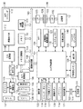
図1は、本発明の第1の実施形態に係る画像供給装置の一例としてのデジタルカメラ100の構成例を示すブロック図である。
Hereinafter, preferred and exemplary embodiments of the present invention will be described with reference to the drawings.
(First embodiment)
FIG. 1 is a block diagram showing a configuration example of a
レンズ101、絞り機能を備えるシャッター102により、撮像素子103に被写体の光学像が結像される。撮像素子103はCCDイメージセンサやCMOSイメージセンサなどの光電変換素子であり、結蔵された光学像を画素単位のアナログ電気信号に変換して出力する。A/D変換器104は、撮像素子103から出力されたアナログ信号をデジタルデータに変換する。
An optical image of the subject is formed on the
タイミング発生部105は、メモリ制御部106及びカメラ制御部107により制御され、撮像素子103、A/D変換器104、D/A変換器108にクロック信号や制御信号を供給する。
The
画像処理部109は、A/D変換器104からのデジタルデータまたはメモリ制御部106からのデジタルデータに対し、画素補間処理や色変換処理等の画像処理を行う。また画像処理部109は、撮像した画像データを用いて所定の演算処理を行い、この演算結果をカメラ制御部107に供給する。画像処理部109はまた、撮像した画像データを用いて所定の演算処理を行い、得られた演算結果に基づいてTTL(スルー・ザ・レンズ)方式のAWB(オートホワイトバランス)処理を実現する。
The image processing unit 109 performs image processing such as pixel interpolation processing and color conversion processing on the digital data from the A /
カメラ制御部107は、画像処理部109からの演算結果に基づき、レンズ101やシャッター102や絞りを制御することにより、TTL方式のAF(オートフォーカス)処理、AE(自動露出)処理を実現する。また、カメラ制御部107は、フラッシュ114を制御して、EF(フラッシュプリ発光)処理を実現する。
The
メモリ制御部106は、A/D変換器104、タイミング発生部105、画像処理部109、D/A変換器108、メモリ110、圧縮伸張部111等を制御する。A/D変換器104からのデジタルデータは、画像処理部109とメモリ制御部106の両方またはメモリ制御部106のみを介して、メモリ110(または別途設けられた画像表示メモリ)に画像データとして書き込まれる。
The
メモリ110に書き込まれた画像データは、D/A変換器108を介して画像表示部112に表示される。画像表示部112は、例えばLCDから構成される。撮像した画像データを逐次、画像表示部112で表示することにより、画像表示部112をEVF(電子ビューファインダ)として機能させることができる。また、画像表示部112は、カメラ制御部107からON/OFF制御可能であり、画像表示部112の表示をOFFにした場合には、デジタルカメラ100の電力消費を低減することができる。そのためユーザは、例えば光学ファインダ113を用いて撮影を行う際に、後述する操作部120を通じて画像表示部112の表示をOFFとするように指示することで、電力消費を低減することが可能である。
The image data written in the
メモリ110には、撮影により得られる静止画像データや動画像データが格納される。メモリ110は所定枚数の静止画像や所定時間の動画像を格納するのに十分な記憶量を備えている。これにより、複数枚の静止画像を連続して撮影する連写撮影やパノラマ撮影に対応することができる。また、メモリ110はカメラ制御部107の作業領域としても使用可能である。
The
圧縮伸張部111は、ADCT(適応離散コサイン変換)等を利用した符号化方式により、メモリ110に格納された画像データの符号化(圧縮)や、符号化済みの画像データの復号化(伸長)を行い、処理結果を再びメモリ110に書き込む。
The compression / decompression unit 111 encodes (compresses) image data stored in the
バリア128はレンズ101の前面に設けられた保護部材であり、カメラ制御部107の制御に従って開閉する。
The
カメラ制御部107は例えばマイクロコンピュータであり、例えば不揮発性メモリ116に記憶されたプログラムを実行して各部を制御することにより、デジタルカメラ100の動作を制御する。
The
システムメモリ115は、カメラ制御部107の動作用の定数、変数、プログラム等を記憶する。システムメモリ115はまた、AE制御で用いるプログラム線図も格納している。なお、プログラム線図は、被写体輝度に対する絞り値とシャッター速度の関係を予め定義したテーブルである。
The
不揮発性メモリ116は例えばカメラ制御部107が実行するプログラムや、各種の設定値などを記憶する。不揮発性メモリ116は例えばEEPROMのように電気的に書き換え可能なメモリであってよい。
The
モード切替スイッチ117は、電源OFF、自動撮影モード、撮影モード、パノラマ撮影モード、再生モード、マルチ画面再生・消去モード、PC接続モード等、ユーザが電源ON/OFFや動作モードの切り替え指示を入力するためのスイッチである。 A mode switch 117 is used to input a power ON / OFF or operation mode switching instruction such as power OFF, automatic shooting mode, shooting mode, panoramic shooting mode, playback mode, multi-screen playback / erase mode, and PC connection mode. It is a switch for.
シャッタースイッチ(SW1)118は、不図示のシャッターボタンの操作途中(半押し)でONとなる。シャッタースイッチ118のON入力により、カメラ制御部107は、AF(オートフォーカス)処理、AE(自動露出)処理、AWB(オートホワイトバランス)処理、EF(フラッシュプリ発光)処理等の動作を開始する。
The shutter switch (SW1) 118 is turned on during operation (half-press) of a shutter button (not shown). When the
シャッタースイッチ(SW2)119は、不図示のシャッターボタンの操作完了(全押し)でONとなる。シャッタースイッチ119のON入力により、カメラ制御部107は、撮影に関わる一連の動作、即ち、露光処理、現像処理、記録処理を実行する。露光処理では、撮像素子103からのアナログ信号が、A/D変換器104、メモリ制御部106を介してデジタルデータとしてメモリ110に書き込まれる。現像処理では、画像処理部109やメモリ制御部106がデジタルデータに対して画像処理を適用することによりデジタル画像データが生成され、メモリ110に書き込まれる。記録処理では、メモリ110から画像データが読み出され、圧縮伸張部111で符号化され、例えばExif画像ファイルの形式で記録媒体199に書き込まれる。
The shutter switch (SW2) 119 is turned on when the operation of a shutter button (not shown) is completed (fully pressed). When the
操作部120は、各種機能の設定や、メニュー操作を行うためのボタン、スイッチ、キー、タッチパネル等の入力デバイス群である。操作部120には、例えば、メニューボタン、セット(実行)ボタン、4方向ボタン、マクロボタン、フラッシュ設定ボタン、単写/連写/セルフタイマー切り替えボタン、撮影画質選択ボタン、露出補正ボタン、日付/時間設定ボタン等が含まれる。
The
また、本実施形態のデジタルカメラ100は、動画撮影の開始と終了を指示するための動画ボタン138を操作部120とは別に備える。動画撮影されていないときに動画ボタン138が押下されると動画撮影開始となり、動画撮影中に動画ボタン138が押下されると動画撮影終了となる。
In addition, the
電源制御部121は、電池検出回路、DC−DCコンバータ、通電するブロックを切り替えるスイッチ回路等により構成される。これらの構成により、電源制御部121は、電池の装着の有無、電池の種類、電池残量の検出を行う。電源制御部121は、これらの検出結果及びカメラ制御部107の指示に基づいてDC−DCコンバータを制御し、必要な電圧を必要な期間、記録媒体を含む各部へ供給する。
The power
電源制御部121はコネクタ122、123を介して電源部124に接続される。電源部124としては、アルカリ電池やリチウム電池等の一次電池、NiCd電池やNiMH電池、Liイオン電池等の二次電池、ACアダプタ等を用いることができる。
The power
インターフェイス(I/F)125はメモリカードやハードディスク等の記録媒体199と内部バス160とを接続する。コネクタ126は、メモリカードやハードディスク等の記録媒体199が有するコネクタ133と電気的及び機械的に着脱可能である。記録媒体着脱検知部127は、コネクタ126に記録媒体199が装着されているか否かを検知する。
An interface (I / F) 125 connects a
RTC134(Real Time Clock)は、カメラ制御部107の制御の下、時刻情報を出力する。なお、RTC134は、電源制御部121とは別の内部電源を備え、電源部124からの電源供給がない状態であっても、計時可能に構成されている。カメラ制御部107は、RTC134を用いてタイマー制御を行う。
An RTC 134 (Real Time Clock) outputs time information under the control of the
なお、本実施形態のデジタルカメラ100は記録媒体199を取り付けるインターフェイス125及びコネクタ126を1組有しているが、複数組有していても良い。また、複数組有する場合には、異なる規格のインターフェイス及びコネクタを組み合わせて備える構成としても構わない。記録媒体199の代わりに通信カードをコネクタ126に接続することにより、他のコンピュータやプリンタ等の周辺機器との間で画像データや画像データに付属した管理情報を例えば相互に通信することができる。
Note that the
通信部129は、外部装置と、シリアルまたはパラレル通信を、有線または無線により行う。コネクタ/アンテナ130は通信部129が有線通信する場合にはコネクタであり、無線通信する場合にはアンテナである。
The
記録媒体199はデジタルカメラ100に対して着脱可能であり、代表的には半導体メモリカードや小型ハードディスクである。記録媒体199は、半導体メモリや磁気ディスク等から構成される記録部131、デジタルカメラ100と記録部131とのインターフェイス132及び、コネクタ126と電気的及び機械的に着脱可能なコネクタ133を備えている。
The
なお、デジタルカメラ100の制御を行うカメラ制御部107は、1つのハードウェアであっても良いし、処理を分担する複数のハードウェアから構成されていても良い。
本実施形態において、画像データは予め記録媒体199(記録部131)に保存されているものとする。
Note that the
In the present embodiment, it is assumed that the image data is stored in advance in the recording medium 199 (recording unit 131).
近接通信部140は、予め定められた通信プロトコルに従って、外部機器と近接無線通信を行う。なお、本明細書において、「近接無線通信」とは、通信距離が1m未満、特には数10cm未満であることを想定して規定された通信プロトコルに基づく無線通信を意味するものとする。このような通信プロトコルとしては、通信距離が約70cm以下の「近傍型」、同約10cm以下の「近接型」非接触通信プロトコルが知られている。具体的には、ISO/IEC 15693、ISO/IEC 14434、ECMA-340 (ISO/IEC 18092)などの規格が存在する。
The close
近接通信部140は、他の機器が有する近接通信部が所定の通信距離内に存在する場合に通信可能である。また、通信していた他の機器の近接通信部が通信距離外に離れた場合には通信を解除する。
The
図2は、本実施形態のデジタルカメラ100の背面外観例を示す図である。図2において、図1と同じ構成要素には同じ参照数字を付し、重複する説明を省略する。
FIG. 2 is a diagram illustrating an example of the rear appearance of the
図3は、本発明の第1の実施形態に係る画像形成装置の一例としてのプリンタの構成例を示すブロック図である。本実施形態において、プリンタ201はインクジェットプリンタとするが、電子写真方式や熱転写方式を始め、記録方式はどのような方式であっても良い。
FIG. 3 is a block diagram illustrating a configuration example of a printer as an example of the image forming apparatus according to the first embodiment of the present invention. In this embodiment, the
プリンタ201は、プリンタ制御部207の制御により動作する。印刷処理部205は、メモリ209に記憶された印刷用データをビットマップ形式に展開してプリントエンジン202に供給する。プリントエンジン202は給紙部213から用紙を搬送し、カートリッジ装着部215に装着されたプリントヘッドを駆動して、印刷処理部205から供給されるビットマップデータに基づく印刷処理を行う。そして、プリントエンジン202は、印刷処理した用紙を排紙部214から出力する。
The
表示部203はLEDやスピーカーを有し、表示処理部206の制御に従ってLEDを点灯・点滅させたり、ビープ音や音声メッセージを出力することにより、プリンタ201の動作状態や警告などをユーザに報知する。
The
操作部204はスイッチやダイアルなどを含み、ユーザがプリンタ201に各種の指示を入力するためのユーザインタフェースである。なお、操作部204がマイクと音声認識機能を備え、声で指示するように構成することも可能である。操作部204を介して入力されたユーザの指示は、プリンタ制御部207へ与えられる。
The
不揮発性メモリ208は例えば電気的に書き換え可能であり、プリンタ201の各種設定内容や管理情報、プリンタ制御部207が実行するプログラムなど、プリンタ201の動作上必要な情報が記憶される。
The
近接通信部216はアンテナ217を用いて外部装置との間で近接無線通信を行う。本実施形態において、デジタルカメラ100の近接通信部140と、プリンタ201の近接通信部216とは同じ近接無線通信プロトコルをサポートしているものとする。従って、近接通信部216と近接通信部140とが通信可能な距離に近づくと、両者の間での通信が可能となる。
The near
USBホストインターフェイス(USB Host I/F)211は、パーソナルコンピュータ等の外部ホスト機器を接続するためのインタフェースである。また、USBデバイスインターフェイス(USB Device I/F)212は、デジタルカメラ100等の外部デバイス機器を接続するためのインターフェイスである。
A USB host interface (USB Host I / F) 211 is an interface for connecting an external host device such as a personal computer. A USB device interface (USB Device I / F) 212 is an interface for connecting an external device such as the
上述の通り、本実施形態において、デジタルカメラ100とプリンタ201とは、近接通信部140及び216を介した近接無線通信を行う。より具体的には、デジタルカメラ100とプリンタ201との間でダイレクトプリントを行うための通信に近接無線通信を用いる。
As described above, in the present embodiment, the
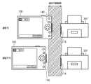
図4は、本実施形態におけるデジタルカメラ100とプリンタ201との間の近接無線通信を模式的に示す図である。
近接無線通信において通信可能な距離(通信距離)は短く、例えば図4下段に示すように、プリンタ201の近接通信部216の通信距離外にデジタルカメラ100の近接通信部140がある場合には、通信を行うことができない。従って、例えば図4上段に示す通信可能な状態から下段に示す状態になった場合には、通信は切断される。
FIG. 4 is a diagram schematically illustrating close proximity wireless communication between the
For example, when the
なお、本実施形態において、近接通信部140及び216は、送信モードと受信モードのいずれかで動作可能である。また、本実施形態においては、送信モードの通信部と受信モードの通信部とが通信距離内に近接すると、互いに動作モードを交換し、ユーザが操作することなしに、送信モードの通信部から受信モードの通信部へデータが送信されるものとする。
In the present embodiment, the
なお、プリンタ201は印刷用のデータを外部装置から受信するのが一般的であるため、プリンタ201が印刷可能な状態では近接通信部216は受信モードで動作するように設定されている。一方、デジタルカメラ100は画像データを外部装置に送信するのが一般的であるため、近接通信部140は、少なくとも印刷する画像データがある場合には送信モードで動作するように設定されている。もちろん、動作モードは、ユーザが変更可能であってよい。
Since the
図5は、本実施形態におけるプリンタ201とデジタルカメラ100とを用いたダイレクトプリント処理の流れを模式的に示す図である。
まず、プリンタ201及びデジタルカメラ100とにおいて、少なくとも近接通信部216及び140が通信待機状態であるとする。通信待機状態において、近接通信部216及び140は、通信距離内に他の機器が存在するかどうかを検出する動作、もしくは問い合わせ信号を送信したり、他の機器からの問い合わせ信号が受信されたかどうかを検出したりする動作を行っている。なお、通信待機状態における動作は、近接通信部216及び140が準拠する通信プロトコルに従って定まり、上述の例に限定されない。
FIG. 5 is a diagram schematically showing the flow of direct print processing using the
First, it is assumed that at least the
S5001でデジタルカメラ100を持ったユーザがプリンタ201に近づき、S50002で近接通信部216及び140が通信距離内に接近したとする。これにより、近接通信部216及び140の間の通信が確立する。この際、デジタルカメラ100の近接通信部140はは自身の識別情報であるIDをプリンタ201の近接通信部216に送信する。近接通信部216は、受信した近接通信部140のIDを保持しておく。
Assume that the user with the
通信が確立すると、カメラ制御部107は、記録媒体199の記録部131から印刷する画像データを読み出し、近接通信部140を通じてプリンタへ送信する。プリンタ制御部207は、アンテナ217および近接通信部216を通して受信した画像データをメモリ209へ転送する。
When communication is established, the
なお、デジタルカメラ100からプリンタ201へ送信する画像データは、例えば通信の確立前にユーザ操作などにより印刷対象として選択されていてもよい。また、記録媒体199に保存されている全ての画像データを印刷する画像データとして送信するようにしてもよい。
Note that image data to be transmitted from the
印刷対象の画像データの送信が全て完了すると、近接通信部140は近接通信部216との通信を切断する。したがって、デジタルカメラ100のユーザは、画像データの印刷が完了するまでデジタルカメラ100をプリンタ201との通信可能な距離範囲に維持する必要がない。カメラ制御部107は、例えば画像データの転送中は「カメラをプリンタから遠ざけないで下さい」等のメッセージを画像表示部112に表示することができる。また、画像データの送信が正常に完了し、通信を切断したら、カメラ制御部107は、同様にして「カメラを自由に使用できます」等のメッセージを表示することができる。
When transmission of all the image data to be printed is completed, the
プリンタ制御部207は、メモリ209に転送した画像データを印刷処理部205を用いて展開し、プリントエンジン202に供給して印刷処理を実行する。
The
ここで、印刷処理中に用紙切れ、用紙詰まり、インク切れなどのエラーが発生したとする(S5003)。エラーの発生を検知すると、エラー検知手段としてのプリンタ制御部207は、表示処理部206を通じて表示部203のLEDやスピーカを用いてエラーの発生を報知する。この際、プリンタ制御部207は、エラー報知の一環として、音声メッセージやLEDの点灯などにより、電源ON状態のデジタルカメラ100をプリンタ201に近づけるようユーザに促すことができる。
Here, it is assumed that an error such as out of paper, paper jam, or out of ink has occurred during the printing process (S5003). When the occurrence of an error is detected, the
また、プリンタ制御部207は、近接通信部216の動作モードを送信モードに切り替える。また、プリンタ制御部207は、近接通信部216を通じて送信するためのエラー情報を生成する。後述するように、エラー情報は、デジタルカメラ100の画像表示部112を通じて、プリンタ201で発生したエラーを報知するための表示情報であってよい。
In addition, the
S5004で、ユーザがデジタルカメラ100をプリンタ201に近づけ、近接通信部140及び216とが通信距離内に接近すると、S5005で通信が確立する。
In S5004, when the user brings the
通信確立時の処理において、デジタルカメラ100の近接通信部140はIDを送信する。プリンタ201の近接通信部216は保持しているIDと受信したIDとを比較する。近接通信部216は、デジタルカメラ100から受信したIDが保持しているIDと一致すれば、通信を続行する。IDが異なる場合、近接通信部216は通信を切断する。これにより、エラーが発生した印刷処理を依頼したデジタルカメラ100以外との通信を防止し、処理依頼元であるデジタルカメラ100に確実にエラー情報を通知することが可能となる。このように、本実施形態のプリンタ201は、印刷処理を依頼した(画像データを供給した)装置と、通信が切断された後に再度通信可能になると、エラー情報を通知する。
In the process at the time of establishing communication, the near
後述するように、本実施形態において、デジタルカメラ100は、S5002で画像データの送信が完了すると、近接通信部140の動作モードを受信モードに切り替えている。そのため、S5004の時点では近接通信部140が受信モード、近接通信部216が送信モードに設定されている。
As will be described later, in the present embodiment, the
S5005において、プリンタ201からアンテナ217を通してデジタルカメラ100へエラー情報が転送される。
エラー情報の転送が完了すると近接通信部216は通信を切断する。S5006で、カメラ制御部107は、受信したエラー情報を画像表示部112に表示させる。これにより、ユーザは、プリンタ201で発生したエラーの内容やその解決方法を詳細かつ容易に理解することができる。
In step S <b> 5005, error information is transferred from the
When the transfer of the error information is completed, the near
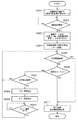
図6は、図5におけるプリンタ201の動作を詳細に説明するためのフローチャートである。
S601でプリンタ制御部207は、例えば初期化処理など、印刷処理の受け付けに必要な動作が完了したならば、近接通信部216を有効にする。これにより、近接通信部216は、準拠するプロトコルに従った通信待機状態となる。本実施形態では、通信待機状態において、通信相手の探索動作を実行するものとする。
FIG. 6 is a flowchart for explaining the operation of the
In step S <b> 601, the
S602でプリンタ制御部207は、近接通信部216が送信モードに設定された通信相手(送信相手)を発見するのを待つ。送信モードに設定された通信相手(ここではデジタルカメラ100であるとする)を近接通信部216が発見すると、プリンタ制御部207は、通信相手から送信された画像データを近接通信部216を用いて受信する。また、この際、近接通信部216は、デジタルカメラ100の識別情報として近接通信部140のIDを受信し、保持する。プリンタ制御部207は、受信した画像データをメモリ209に転送する。
In step S602, the
S603で、画像データの受信が完了すると、プリンタ制御部207は近接通信部216による通信の終了をデジタルカメラ100に通知し、近距離無線通信の受信を無効にする。
S604でプリンタ制御部207は、印刷処理部205及びプリントエンジン202を用いて、メモリ209に転送した画像データの印刷処理を開始させる。
S605でプリンタ制御部207は印刷処理が終了したかチェックし、終了していれば処理をS613に進め、終了していなければ処理をS606に進める。
In step S <b> 603, when the reception of the image data is completed, the
In step S <b> 604, the
In step S605, the
S606でプリンタ制御部207は、印刷処理中にエラーが発生したかどうかをチェックし、エラーが発生していなければ処理をS605に戻す。エラーが発生していた場合、S607でプリンタ制御部207は、表示処理部206を用いて、表示部203のLEDやスピーカから、発生したエラーに応じた報知を行う。また、プリンタ制御部207は、近接通信部216の動作モードを送信モードに切り替え、通信待機状態にする。また、プリンタ制御部207は、発生したエラーに応じたエラー情報を例えば不揮発性メモリ208から読み出し、メモリ209に転送しておく。
In step S606, the
S608でプリンタ制御部207は、エラーが発生した印刷処理を依頼した(画像データを供給した)通信相手を近接通信部216が発見したかどうかをチェックする。上述のように、近接通信部216は印刷対象のデータの送信元装置(本実施形態ではデジタルカメラ100)の識別情報(近接通信部140のID)を保持し、IDを比較することで、発見した通信相手が送信元装置か否かを判別する。
In step S <b> 608, the
エラーが発生した印刷処理の依頼元の通信相手を近接通信部216が発見した場合、プリンタ制御部207は、S609でメモリ209からエラー情報を読み出し、近接通信部216及びアンテナ217を通じて送信する。
When the
S608で、エラーが発生した印刷処理の依頼元の通信相手を近接通信部216が発見できていない場合、または、S609でエラー情報を送信した後、プリンタ制御部207は、S610で印刷キャンセル指示の有無を確認する。
In S608, when the
例えば操作部204を通じて印刷のキャンセルが指示されている場合、プリンタ制御部207は処理をS613に進める。
印刷キャンセルが指示されていない場合、S611でプリンタ制御部207は発生したエラーが解除されたかどうか判定する。エラーが解除されていればS612でプリンタ制御部207は、印刷処理を再開させるとともに、近接通信部216を無効とし、処理をS605に戻す。
For example, if canceling printing is instructed through the
If print cancel is not instructed, the
S611でエラーが解除されていない場合、プリンタ制御部207は処理をS608に戻す。また、S613でプリンタ制御部207は、印刷処理を受け付け可能な状態にするために必要な処理(印刷終了処理)を行うとともに、近接通信部216を受信モードに設定して有効化する。
If the error has not been canceled in S611, the
図7は、エラー情報の一例およびその表示例を示す図である。
図7は、デジタルカメラ100の画像表示部112にエラー情報が表示された状態の例を示す図である。
FIG. 7 is a diagram illustrating an example of error information and a display example thereof.
FIG. 7 is a diagram illustrating an example of a state in which error information is displayed on the
エラー情報は、エラーの発生場所(装置)を示す情報701、エラーの内容を示す情報702、エラーの解除方法を示す情報703を含んでいる。図7では、エラー発生場所については絵で、エラーの内容及び解除方法については文字で表したエラー情報の例を示す。
The error information includes
上述のように、本実施形態のプリンタ201は、印刷処理中に発生しうるエラーに応じたエラー情報を予め不揮発性メモリ208に記憶しておき、発生したエラーに対応したエラー情報を送信する。そして、カメラ制御部107は、受信したエラー情報を画像表示部112に表示させる。
As described above, the
これにより、印刷処理を実行したユーザ(デジタルカメラ100のユーザ)は、何処でどのようなエラーが発生したのかを、プリンタ201の表示部203による報知よりも遙かに容易に理解することができる。また、どのようにしてエラーを解消できるのかについても知ることが可能になる。
Accordingly, the user who executed the printing process (the user of the digital camera 100) can understand where and what kind of error has occurred much more easily than the notification by the
図8は、デジタルカメラ100の画像表示部112にエラー情報が表示された状態の別の例を示す図である。
図8では、エラー情報がテキストデータのみで構成されている点で図7の例と異なる。本例において、エラー情報は、エラーの内容を示す情報801、エラーの解除方法を示す情報802を含んでいる。もちろん、図7の例と同様、エラーの発生場所(装置)を示す情報を含んでいても良い。この場合、「プリンタでエラーが発生しました」等のテキストデータとすることができる。
FIG. 8 is a diagram illustrating another example of a state in which error information is displayed on the
FIG. 8 differs from the example of FIG. 7 in that the error information is composed only of text data. In this example, the error information includes
デジタルカメラ100は、図8に示すようにエラー情報をテキストデータのまま画像表示部112に表示してもよいし、テキストデータの内容を解析し、対応するアイコンなど、別の表示情報に変換して画像表示部112に表示してもよい。
As shown in FIG. 8, the
図9は、図5の手順におけるデジタルカメラ100の動作を詳細に説明するためのフローチャートである。
S9001でカメラ制御部107は、画像送信の準備が完了したら、近接通信部140を有効化する。この時点で近接通信部140は送信モードである。
FIG. 9 is a flowchart for explaining in detail the operation of the
In step S <b> 9001, the
S9002でカメラ制御部107は、近接通信部140が通信相手(受信相手)を発見するまで待機する。近接通信部140が通信相手を発見すると、カメラ制御部107は、S9003において、近接通信部140を用いて近距離無線通信により画像データをプリンタ201へ送信する。近接通信部140は、通信確立時に、自身の識別情報であるIDをプリンタ201の近接通信部216に送信する。画像データの送信が完了すると、カメラ制御部107は、近接通信部140の動作モードを送信モードから受信モードに切り替える。
In step S9002, the
S9004でカメラ制御部107は、プリンタ201からの近接無線通信を受信し、あわせてタイマによる計時を開始する。具体的には、その時点におけるRTC134の出力をメモリ110に保持する。
S9005でカメラ制御部107は、RTC134を監視し、メモリ110に保持した時刻から所定時間が経過したかどうか判別する。
In step S9004, the
In step S <b> 9005, the
カメラ制御部107は、所定時間経過したと判別される場合、処理をS9011に進める。一方、所定時間が経過していないと判別される場合は、カメラ制御部107はS9006で、操作部120を通じて受信キャンセル指示が入力されていないか判別する。
If it is determined that the predetermined time has elapsed, the
カメラ制御部107は、受信キャンセル指示が入力されていればS9011に、入力されていなければS9007にそれぞれ処理を進める。
S9007でカメラ制御部107は、近接通信部140が通信相手(送信相手)を発見したかどうかを判別する。通信相手が発見できない場合は、カメラ制御部107は処理をS9005に戻し、上述の処理を繰り返す。一方、近接通信部140が通信相手を発見した場合、S9008において、近接通信部140を用いてプリンタ201からエラー情報を受信する。受信したエラー情報は、例えばメモリ110に一旦保存する。
If the reception cancel instruction has been input, the
In step S9007, the
本実施形態においてカメラ制御部107は、S9004のタイマ開始から所定時間経過するまでに受信した情報はエラー情報とみなし、画像表示部112に表示する。なお、上述のように、エラー情報が画像データやテキストデータなど表示可能な形式であればそのまま表示させてもよい。また、エラー情報を解析して、デジタルカメラ100が保持する情報を表示させても良い。例えば、エラー情報がテキストデータであれば、テキストの内容を解析し、内容を示すアイコンを表示したり、エラー情報がエラー種別を表す識別情報であれば、識別情報に対応するエラーメッセージなどを表示させても良い。デジタルカメラ100においては、例えば不揮発性メモリ116にこれらの情報を予め用意しておくことができる。
In the present embodiment, the
S9010でカメラ制御部107は、表示された画像をユーザが確認し、操作部120から確認入力がなされるまで待機する。そして、カメラ制御部107は、操作部120を通じて確認入力があったならば、処理をS9005に戻す。
In step S9010, the
S9005において所定時間の経過が判別された場合、もしくはS9006においてユーザの受信キャンセル指示の入力が判別された場合、カメラ制御部107はS9011において、終了処理を行い、近接通信部140を無効化する。
If it is determined in S9005 that the predetermined time has elapsed, or if it is determined in S9006 that the user has input a reception cancellation instruction, the
(他の実施形態)
上述の実施形態においては、画像形成装置と近接無線通信が可能な外部装置の一例としてのデジタルカメラを用いて説明した。しかしながら、近接無線通信可能で、エラー情報の表示が可能な表示装置を有する任意の外部装置、例えば、携帯電話、携帯情報端末(PDA)、フォトビューワーなどであってよい。
(Other embodiments)
In the above-described embodiment, the description has been given using the digital camera as an example of the external apparatus capable of performing close proximity wireless communication with the image forming apparatus. However, it may be any external device having a display device capable of performing near field communication and displaying error information, such as a mobile phone, a personal digital assistant (PDA), a photo viewer, and the like.
また、上述の実施形態では、デジタルカメラ100が、画像データの送信完了時点で近接通信部140の動作モードを受信モードに切り替えた。しかし、エラー発生中の印刷装置と近接し、通信確立時のモード交換時に通信相手が送信モードであることを検出したことに応答して、受信モードに切り替えるようにしても良い。このようにすることで、デジタルカメラ100は基本的に送信モードとなる。したがってデジタルカメラ100のユーザは、図9のS9005に示す所定時間の待機や、S9006に示すキャンセル操作を行わなくとも、すぐに次の画像データを送信することが可能となる。
In the above-described embodiment, the
また、上述の実施形態では、デジタルカメラ100が、画像データの送信後、所定時間内に受信したデータをエラー情報とみなす場合を説明した。しかし、プリンタ201から送信するエラー情報に、情報の種別を表す情報を含めておき、カメラ制御部107がその情報を参照してエラー情報であることを検出するなど、他の方法によりエラー情報の受信を判別しても良い。
In the above-described embodiment, the case has been described in which the
また、上述の実施形態では、送信モードと受信モードという2つのモードを用いて説明したが、必ずしもこの2つのモードを有する必要はなく、コマンドの送受信のみで通信を制御することも可能である。例えば一方の機器からデータ送信通知コマンドを送信し、もう一方の機器はそれに応答して許可コマンドを送信することで、送受信の関係を決定することも可能である。 In the above-described embodiment, the two modes of the transmission mode and the reception mode have been described. However, it is not always necessary to have these two modes, and the communication can be controlled only by transmitting and receiving commands. For example, it is also possible to determine a transmission / reception relationship by transmitting a data transmission notification command from one device and the other device transmitting a permission command in response thereto.
上述の実施形態は、システム或は装置のコンピュータ(或いはCPU、MPU等)によりソフトウェア的に実現することも可能である。
従って、上述の実施形態をコンピュータで実現するために、該コンピュータに供給されるコンピュータプログラム自体も本発明を実現するものである。つまり、上述の実施形態の機能を実現するためのコンピュータプログラム自体も本発明の一つである。
The above-described embodiment can also be realized in software by a computer of a system or apparatus (or CPU, MPU, etc.).
Therefore, the computer program itself supplied to the computer in order to implement the above-described embodiment by the computer also realizes the present invention. That is, the computer program itself for realizing the functions of the above-described embodiments is also one aspect of the present invention.
なお、上述の実施形態を実現するためのコンピュータプログラムは、コンピュータで読み取り可能であれば、どのような形態であってもよい。例えば、オブジェクトコード、インタプリタにより実行されるプログラム、OSに供給するスクリプトデータ等で構成することができるが、これらに限るものではない。 The computer program for realizing the above-described embodiment may be in any form as long as it can be read by a computer. For example, it can be composed of object code, a program executed by an interpreter, script data supplied to the OS, but is not limited thereto.
上述の実施形態を実現するためのコンピュータプログラムは、記憶媒体又は有線/無線通信によりコンピュータに供給される。プログラムを供給するための記憶媒体としては、例えば、フレキシブルディスク、ハードディスク、磁気テープ等の磁気記憶媒体、MO、CD、DVD等の光/光磁気記憶媒体、不揮発性の半導体メモリなどがある。 A computer program for realizing the above-described embodiment is supplied to a computer via a storage medium or wired / wireless communication. Examples of the storage medium for supplying the program include a magnetic storage medium such as a flexible disk, a hard disk, and a magnetic tape, an optical / magneto-optical storage medium such as an MO, CD, and DVD, and a nonvolatile semiconductor memory.
有線/無線通信を用いたコンピュータプログラムの供給方法としては、コンピュータネットワーク上のサーバを利用する方法がある。この場合、本発明を形成するコンピュータプログラムとなりうるデータファイル(プログラムファイル)をサーバに記憶しておく。プログラムファイルとしては、実行形式のものであっても、ソースコードであっても良い。 As a computer program supply method using wired / wireless communication, there is a method of using a server on a computer network. In this case, a data file (program file) that can be a computer program forming the present invention is stored in the server. The program file may be an executable format or a source code.
そして、このサーバにアクセスしたクライアントコンピュータに、プログラムファイルをダウンロードすることによって供給する。この場合、プログラムファイルを複数のセグメントファイルに分割し、セグメントファイルを異なるサーバに分散して配置することも可能である。
つまり、上述の実施形態を実現するためのプログラムファイルをクライアントコンピュータに提供するサーバ装置も本発明の一つである。
Then, the program file is supplied by downloading to a client computer that has accessed the server. In this case, the program file can be divided into a plurality of segment files, and the segment files can be distributed and arranged on different servers.
That is, a server apparatus that provides a client computer with a program file for realizing the above-described embodiment is also one aspect of the present invention.
また、上述の実施形態を実現するためのコンピュータプログラムを暗号化して格納した記憶媒体を配布し、所定の条件を満たしたユーザに、暗号化を解く鍵情報を供給し、ユーザの有するコンピュータへのインストールを許可してもよい。鍵情報は、例えばインターネットを介してホームページからダウンロードさせることによって供給することができる。 In addition, a storage medium in which the computer program for realizing the above-described embodiment is encrypted and distributed is distributed, and key information for decrypting is supplied to a user who satisfies a predetermined condition, and the user's computer Installation may be allowed. The key information can be supplied by being downloaded from a homepage via the Internet, for example.
また、上述の実施形態を実現するためのコンピュータプログラムは、すでにコンピュータ上で稼働するOSの機能を利用するものであってもよい。
さらに、上述の実施形態を実現するためのコンピュータプログラムは、その一部をコンピュータに装着される拡張ボード等のファームウェアで構成してもよいし、拡張ボード等が備えるCPUで実行するようにしてもよい。
Further, the computer program for realizing the above-described embodiment may use an OS function already running on the computer.
Further, a part of the computer program for realizing the above-described embodiment may be configured by firmware such as an expansion board attached to the computer, or may be executed by a CPU provided in the expansion board. Good.
Claims (9)
前記通信手段を通じて前記外部装置から受信したデータを印刷する印刷手段と、
前記印刷手段による印刷処理中のエラーを検知するエラー検知手段とを有する画像形成装置であって、
前記通信手段を通じて外部装置からデータを受信したならば、前記外部装置との通信を切断し、前記受信したデータを前記印刷手段により印刷させるとともに、
前記受信したデータの印刷処理について前記エラー検知手段によりエラーが検知された後に、前記通信手段を通じて前記外部装置と再度通信可能になった際に、前記エラー検知手段が検知したエラーを表すエラー情報を前記通信手段を通じて前記外部装置へ送信させる、
制御手段を有することを特徴とする画像形成装置。 Communication means for communicating with an external device by proximity wireless communication;
Printing means for printing data received from the external device through the communication means;
An image forming apparatus having an error detection unit that detects an error during printing processing by the printing unit,
If data is received from the external device through the communication means, the communication with the external device is disconnected, and the received data is printed by the printing means.
Error information indicating the error detected by the error detection unit when the error detection unit detects an error in the received data printing process and becomes able to communicate with the external device again through the communication unit. Transmitting to the external device through the communication means ;
An image forming apparatus comprising a control unit.
前記制御手段は、前記画像形成装置が印刷可能な状態では、前記通信手段を受信モードに設定するとともに、前記エラー検知手段がエラーを検知したならば、前記通信手段を送信モードに設定することを特徴とする請求項1乃至請求項3のいずれか1項に記載の画像形成装置。 The communication means operates in either a reception mode or a transmission mode;
The control unit sets the communication unit to a reception mode when the image forming apparatus is printable, and sets the communication unit to a transmission mode when the error detection unit detects an error. The image forming apparatus according to claim 1, wherein the image forming apparatus is an image forming apparatus.
前記通信手段を通じて通信可能な画像形成装置に対し、印刷するデータを前記通信手段を用いて送信させるとともに、
前記印刷するデータを送信した画像形成装置との通信が切断された後、予め定めた時間内に前記通信手段を通じて画像形成装置からデータを受信した場合、前記受信したデータをエラー情報と見なし、前記表示手段に前記エラー情報に基づく表示を行う、
制御手段を有することを特徴とする画像供給装置。 An image supply device having communication means for communicating with an image forming apparatus by proximity wireless communication, and display means,
The image forming apparatus capable of communicating through the communication unit is caused to transmit data to be printed using the communication unit, and
When data is received from the image forming apparatus through the communication unit within a predetermined time after communication with the image forming apparatus that has transmitted the data to be printed is disconnected, the received data is regarded as error information, and Display on the display means based on the error information ;
An image supply apparatus comprising a control unit.
前記制御手段は、前記画像供給装置が前記印刷するデータを有する状態では、前記通信手段を送信モードに設定するとともに、前記印刷するデータを送信した画像形成装置との通信が切断されると、前記通信手段を受信モードに設定することを特徴とする請求項5記載の画像供給装置。 The communication means operates in either a reception mode or a transmission mode;
The control unit sets the communication unit to a transmission mode in a state where the image supply apparatus has the data to be printed, and disconnects communication with the image forming apparatus that has transmitted the data to be printed. 6. The image supply apparatus according to claim 5, wherein the communication unit is set to a reception mode.
前記制御手段は、前記画像供給装置が前記印刷するデータを有する状態では、前記通信手段を送信モードに設定するとともに、前記印刷するデータを送信した画像形成装置との通信が切断された後、送信モードに設定された通信手段を有する画像形成装置を前記通信手段が検知したならば、前記通信手段を受信モードに設定することを特徴とする請求項5記載の画像供給装置。 The communication means operates in either a reception mode or a transmission mode;
The control unit sets the communication unit to a transmission mode in a state where the image supply apparatus has the data to be printed, and transmits after the communication with the image forming apparatus that has transmitted the data to be printed is disconnected. 6. The image supply apparatus according to claim 5, wherein when the communication unit detects an image forming apparatus having a communication unit set in a mode, the communication unit is set in a reception mode.
前記通信手段を通じて前記外部装置から受信したデータを印刷する印刷手段と、
前記印刷手段による印刷処理中のエラーを検知するエラー検知手段とを有する画像形成装置の制御方法であって、
前記通信手段を通じて外部装置からデータを受信したならば、制御手段が前記外部装置との通信を切断するステップと、
前記受信したデータを前記制御手段が前記印刷手段により印刷させるステップと、
前記受信したデータの印刷処理について前記エラー検知手段によりエラーが検知された後に、前記通信手段を通じて前記外部装置と再度通信可能になった際に、前記受信したデータの印刷処理について前記エラー検知手段が検知したエラーを表すエラー情報を前記制御手段が前記通信手段を通じて前記外部装置へ送信させるステップとを有することを特徴とする画像形成装置の制御方法。 Communication means for communicating with an external device by proximity wireless communication;
Printing means for printing data received from the external device through the communication means;
An image forming apparatus control method comprising: an error detection unit that detects an error during printing processing by the printing unit;
If data is received from the external device through the communication means, the control means disconnects communication with the external device;
Causing the control means to print the received data by the printing means;
When an error is detected by the error detection unit with respect to the print processing of the received data , when the communication with the external apparatus becomes possible again through the communication unit, the error detection unit with respect to the print processing of the received data A control method for an image forming apparatus, comprising: a step of causing the control means to transmit error information representing a detected error to the external apparatus through the communication means.
制御手段が、前記通信手段を通じて通信可能な画像形成装置に対し、印刷するデータを前記通信手段を用いて送信するステップと、
前記制御手段が、前記印刷するデータを送信した画像形成装置との通信が切断された後、予め定めた時間内に前記通信手段を通じて画像形成装置からデータを受信した場合、前記受信したデータをエラー情報と見なし、前記表示手段に前記エラー情報に基づく表示を行うステップとを有することを特徴とする画像供給装置の制御方法。 A control method of an image supply apparatus having a communication means for communicating with an image forming apparatus by proximity wireless communication, and a display means,
And step control means to transmit said the image forming apparatus that can communicate through the communication means, the data to be printed by using said communication means,
If the control unit receives data from the image forming apparatus through the communication unit within a predetermined time after the communication with the image forming apparatus that has transmitted the data to be printed is disconnected, the received data is regarded as an error. A method for controlling the image supply apparatus, comprising: displaying the information based on the error information on the display unit.
Priority Applications (1)
| Application Number | Priority Date | Filing Date | Title |
|---|---|---|---|
| JP2008171240A JP5129669B2 (en) | 2008-06-30 | 2008-06-30 | Image forming apparatus and control method thereof, image supply apparatus and control method thereof |
Applications Claiming Priority (1)
| Application Number | Priority Date | Filing Date | Title |
|---|---|---|---|
| JP2008171240A JP5129669B2 (en) | 2008-06-30 | 2008-06-30 | Image forming apparatus and control method thereof, image supply apparatus and control method thereof |
Publications (3)
| Publication Number | Publication Date |
|---|---|
| JP2010006016A JP2010006016A (en) | 2010-01-14 |
| JP2010006016A5 JP2010006016A5 (en) | 2011-08-18 |
| JP5129669B2 true JP5129669B2 (en) | 2013-01-30 |
Family
ID=41587034
Family Applications (1)
| Application Number | Title | Priority Date | Filing Date |
|---|---|---|---|
| JP2008171240A Expired - Fee Related JP5129669B2 (en) | 2008-06-30 | 2008-06-30 | Image forming apparatus and control method thereof, image supply apparatus and control method thereof |
Country Status (1)
| Country | Link |
|---|---|
| JP (1) | JP5129669B2 (en) |
Families Citing this family (10)
| Publication number | Priority date | Publication date | Assignee | Title |
|---|---|---|---|---|
| JP6006508B2 (en) | 2012-03-05 | 2016-10-12 | キヤノン株式会社 | Information processing system, information processing method, and program |
| JP6066575B2 (en) * | 2012-03-05 | 2017-01-25 | キヤノン株式会社 | Printing apparatus, printing system, and control method |
| WO2013145564A1 (en) * | 2012-03-27 | 2013-10-03 | パナソニック株式会社 | Electrical apparatus |
| JP5983269B2 (en) * | 2012-10-04 | 2016-08-31 | コニカミノルタ株式会社 | Image forming apparatus and control program |
| JP6270354B2 (en) | 2013-06-28 | 2018-01-31 | キヤノン株式会社 | COMMUNICATION DEVICE, ITS CONTROL METHOD, PROGRAM |
| JP6180220B2 (en) | 2013-07-31 | 2017-08-16 | キヤノン株式会社 | Processing system and control method |
| JP2015035728A (en) * | 2013-08-09 | 2015-02-19 | 株式会社リコー | Portable terminal device and program |
| JP6333017B2 (en) * | 2014-03-28 | 2018-05-30 | キヤノン株式会社 | Program and image processing apparatus |
| JP6387925B2 (en) * | 2015-09-01 | 2018-09-12 | コニカミノルタ株式会社 | Image processing system, image processing apparatus, and program |
| JP6263237B2 (en) * | 2016-07-08 | 2018-01-17 | キヤノン株式会社 | Information processing system, information processing method, and program |
Family Cites Families (10)
| Publication number | Priority date | Publication date | Assignee | Title |
|---|---|---|---|---|
| JP3927637B2 (en) * | 1996-12-27 | 2007-06-13 | キヤノン株式会社 | Printing apparatus and printing method |
| JP2001344655A (en) * | 2000-05-31 | 2001-12-14 | Sony Corp | Device/method for processing information, parking managing system and recording medium |
| JP2003288194A (en) * | 2002-03-27 | 2003-10-10 | Mitsubishi Electric Corp | Print system and printing method |
| JP2004237713A (en) * | 2002-12-12 | 2004-08-26 | Seiko Epson Corp | System, device, and method for image output picture supply device, and control program |
| JP2005020305A (en) * | 2003-06-25 | 2005-01-20 | Olympus Corp | Electronic camera |
| JP2007174247A (en) * | 2005-12-21 | 2007-07-05 | Sharp Corp | Transmitter, receiver, transmission program, receive program, and recoding medium |
| JP4795133B2 (en) * | 2006-06-23 | 2011-10-19 | キヤノン株式会社 | Image forming apparatus, image processing method, and control program for executing the method |
| JP4933304B2 (en) * | 2006-10-16 | 2012-05-16 | キヤノン株式会社 | Image processing apparatus, control method thereof, and program |
| JP5049900B2 (en) * | 2008-06-30 | 2012-10-17 | キヤノン株式会社 | SETTING DEVICE, IMAGE OUTPUT DEVICE, CONTROL METHOD AND PROGRAM THEREOF |
| JP5084640B2 (en) * | 2008-06-30 | 2012-11-28 | キヤノン株式会社 | Data receiving apparatus, data transmitting apparatus, control method and program thereof |
-
2008
- 2008-06-30 JP JP2008171240A patent/JP5129669B2/en not_active Expired - Fee Related
Also Published As
| Publication number | Publication date |
|---|---|
| JP2010006016A (en) | 2010-01-14 |
Similar Documents
| Publication | Publication Date | Title |
|---|---|---|
| JP5129669B2 (en) | Image forming apparatus and control method thereof, image supply apparatus and control method thereof | |
| US9154651B2 (en) | Configuring apparatus, image output apparatus, methods of controlling the same, and program | |
| JP5084640B2 (en) | Data receiving apparatus, data transmitting apparatus, control method and program thereof | |
| US8289550B2 (en) | Image output system and control method thereof, image input apparatus and control method thereof, and image output apparatus and control method thereof | |
| US9002276B2 (en) | Image providing apparatus, image output apparatus, and image output system | |
| JP5110805B2 (en) | Communication terminal, communication method and program capable of wired and wireless communication | |
| CN106470241B (en) | Communication apparatus and control method thereof | |
| JP2004318396A (en) | Communication system and communication equipment | |
| JP4759372B2 (en) | Communication terminal for informing wireless communication state and control method thereof | |
| JP5495658B2 (en) | Imaging apparatus, printing apparatus, and program | |
| JP2019004422A (en) | Communication device, control method, and program | |
| JP5972085B2 (en) | Data transfer control device, control method thereof, and program | |
| JP2006287734A (en) | Imaging apparatus, image output device and image output system | |
| JP2007243776A (en) | System and method for managing image print, image storage terminal, and print server | |
| JP2007228133A (en) | System for image print management, camera, and apparatus and method for image print management | |
| JP2011061367A (en) | Information processing apparatus and method, and program | |
| JP2013128258A (en) | Imaging device |
Legal Events
| Date | Code | Title | Description |
|---|---|---|---|
| A521 | Written amendment |
Free format text: JAPANESE INTERMEDIATE CODE: A523 Effective date: 20110630 |
|
| A621 | Written request for application examination |
Free format text: JAPANESE INTERMEDIATE CODE: A621 Effective date: 20110630 |
|
| A977 | Report on retrieval |
Free format text: JAPANESE INTERMEDIATE CODE: A971007 Effective date: 20120928 |
|
| TRDD | Decision of grant or rejection written | ||
| A01 | Written decision to grant a patent or to grant a registration (utility model) |
Free format text: JAPANESE INTERMEDIATE CODE: A01 Effective date: 20121005 |
|
| A01 | Written decision to grant a patent or to grant a registration (utility model) |
Free format text: JAPANESE INTERMEDIATE CODE: A01 |
|
| A61 | First payment of annual fees (during grant procedure) |
Free format text: JAPANESE INTERMEDIATE CODE: A61 Effective date: 20121102 |
|
| R151 | Written notification of patent or utility model registration |
Ref document number: 5129669 Country of ref document: JP Free format text: JAPANESE INTERMEDIATE CODE: R151 |
|
| FPAY | Renewal fee payment (event date is renewal date of database) |
Free format text: PAYMENT UNTIL: 20151109 Year of fee payment: 3 |
|
| LAPS | Cancellation because of no payment of annual fees |