JP5119740B2 - VIDEO SIGNAL PROCESSING DEVICE, VIDEO SIGNAL PROCESSING METHOD, VIDEO SIGNAL PROCESSING METHOD PROGRAM, AND RECORDING MEDIUM CONTAINING VIDEO SIGNAL PROCESSING METHOD PROGRAM - Google Patents
VIDEO SIGNAL PROCESSING DEVICE, VIDEO SIGNAL PROCESSING METHOD, VIDEO SIGNAL PROCESSING METHOD PROGRAM, AND RECORDING MEDIUM CONTAINING VIDEO SIGNAL PROCESSING METHOD PROGRAM Download PDFInfo
- Publication number
- JP5119740B2 JP5119740B2 JP2007137572A JP2007137572A JP5119740B2 JP 5119740 B2 JP5119740 B2 JP 5119740B2 JP 2007137572 A JP2007137572 A JP 2007137572A JP 2007137572 A JP2007137572 A JP 2007137572A JP 5119740 B2 JP5119740 B2 JP 5119740B2
- Authority
- JP
- Japan
- Prior art keywords
- frequency component
- video signal
- amount
- high frequency
- variation
- Prior art date
- Legal status (The legal status is an assumption and is not a legal conclusion. Google has not performed a legal analysis and makes no representation as to the accuracy of the status listed.)
- Expired - Fee Related
Links
Images


Landscapes
- Transforming Electric Information Into Light Information (AREA)
- Compression Or Coding Systems Of Tv Signals (AREA)
- Picture Signal Circuits (AREA)
Description
本発明は、映像信号処理装置、映像信号処理方法、映像信号処理方法のプログラム及び映像信号処理方法のプログラムを記録した記録媒体に関し、例えばMPEG(Moving Picture Experts Group)等によるストリーミングデータをデコードした映像信号の処理に適用することができる。本発明は、入力映像信号に含まれる高域成分量の周期的な時間変動量を検出し、この検出結果に基づいて、この周期的な時間変動を抑圧するように映像信号処理の特性を可変することにより、従来に比して一段と確実にフリッカ劣化を低減することができるようにする。またこのフリッカ劣化の低減手法を利用してフリッカ劣化を定量的に計測する。 The present invention relates to a video signal processing device, a video signal processing method, a video signal processing method program, and a recording medium on which a video signal processing method program is recorded, for example, a video obtained by decoding streaming data by MPEG (Moving Picture Experts Group) or the like. It can be applied to signal processing. The present invention detects the periodic temporal fluctuation amount of the high-frequency component contained in the input video signal, and changes the characteristics of the video signal processing so as to suppress the periodic temporal fluctuation based on the detection result. By doing so, it is possible to reduce the flicker deterioration more reliably than in the prior art. Further, the flicker deterioration is quantitatively measured by using the flicker deterioration reduction technique.
従来、モニタ装置等の各種映像機器では、ノイズ低減処理、鮮鋭度強調処理、コントラスト強調処理等の各種映像信号処理により画質を向上している。これらの映像信号処理のうちのコントラスト強調処理に関して、近年、フラットディスプレイ装置等では、入力映像信号を非線型な特性で増幅してコントラストを強調するようにして、入力映像信号の画面内平均輝度レベル、輝度ヒストグラム等に基づいてこの非線型の特性を適応的に変化させ、一段とコントラストを強調して画質を向上している。 Conventionally, in various video devices such as a monitor device, image quality is improved by various video signal processing such as noise reduction processing, sharpness enhancement processing, and contrast enhancement processing. Regarding contrast enhancement processing among these video signal processing, in recent years, in flat display devices and the like, the input video signal is amplified with nonlinear characteristics to enhance contrast, and the average luminance level in the screen of the input video signal is increased. The non-linear characteristics are adaptively changed based on a luminance histogram or the like, and the image quality is improved by further enhancing the contrast.
また近年、映像信号は、例えばMPEG等の符号化処理によりデータ圧縮して伝送されるものもあり、このようにデータ圧縮して伝送させた映像信号は、いわゆるフリッカ劣化が発生する場合がある(鹿喰喜明、青木勝典、中須英輔「動画像符号化における両方向予測の効果の検証 :画質の評価と分析」、テレビジョン学会誌、Vol.50、No.3、1996、pp.391−398)。 In recent years, some video signals are transmitted after being compressed by, for example, encoding processing such as MPEG, and so-called flicker degradation may occur in the video signals transmitted by such data compression ( Yoshiaki Shikaga, Katsunori Aoki, Eisuke Nakasu “Verification of Bidirectional Prediction Effect in Video Coding: Image Quality Evaluation and Analysis”, Television Society Journal, Vol. 50, No. 3, 1996, pp. 391-398) .
ここでフリッカ劣化は、ピクチャータイプに応じて映像信号の高域成分が周期的に変動する現象であり、Iピクチャー、Pピクチャー、Bピクチャーにおけるデータ圧縮の相違により発生する。フリッカ劣化は、ノイズ低減処理、鮮鋭度強調処理、コントラスト強調処理等の映像信号処理により目立つようになる。具体的に、コントラスト強調処理の場合、フリッカ劣化は、高域成分が目立ち易い低コントラストの暗いシーンに対して、暗部の階調を強調する非線型特性によりコントラスト強調処理した場合に目立つようになる。 Here, the flicker degradation is a phenomenon in which the high frequency component of the video signal varies periodically according to the picture type, and is caused by a difference in data compression in the I picture, P picture, and B picture. Flicker degradation becomes conspicuous by video signal processing such as noise reduction processing, sharpness enhancement processing, and contrast enhancement processing. Specifically, in the case of contrast enhancement processing, flicker degradation becomes conspicuous when contrast enhancement processing is performed on a low-contrast dark scene in which high-frequency components tend to be noticeable due to the non-linear characteristics that enhance the gradation of dark areas. .
このフリッカ劣化を防止する方法として、従来、特開平9−224250号公報、特開2005−260902号公報には、輝度信号をガンマ補正してフレーム間で平均輝度レベル差を検出し、このレベル差を抑圧するように輝度信号の信号レベルを補正する方法が提案されている。 As a method for preventing the flicker deterioration, Japanese Patent Application Laid-Open Nos. 9-224250 and 2005-260902 conventionally detect the average luminance level difference between frames by performing gamma correction on the luminance signal, and this level difference. There has been proposed a method of correcting the signal level of the luminance signal so as to suppress the noise.
しかしながら単に線型に映像信号を処理する場合には、これら特開平9−224250号公報、特開2005−260902号公報に開示の手法により、ある程度、フリッカ劣化を低減できるものの、これらに開示の手法は、実用上未だ不十分な問題がある。特に、これらに開示の手法では、近年の映像信号処理である、入力映像信号に応じて動的に特性を切り換えて非線型な特性により映像信号処理する場合には、フリッカ劣化を低減できない問題がある。
本発明は以上の点を考慮してなされたもので、従来に比して一段と確実にフリッカ劣化を低減することができる映像信号処理装置、映像信号処理方法、映像信号処理方法のプログラム及び映像信号処理方法のプログラムを記録した記録媒体を提案しようとするものである。またこのフリッカ劣化の低減手法を利用してフリッカ劣化を定量的に計測する映像信号処理装置、映像信号処理方法を提案する。 The present invention has been made in consideration of the above points. A video signal processing apparatus, a video signal processing method, a program for a video signal processing method, and a video signal that can reduce flicker degradation more reliably than in the past. The present invention intends to propose a recording medium on which a processing method program is recorded. In addition, a video signal processing apparatus and a video signal processing method for quantitatively measuring flicker degradation using this flicker degradation reduction method are proposed.
上記の課題を解決するために、ある観点によれば、入力映像信号を映像信号処理して出力映像信号を生成する映像信号処理部と、前記入力映像信号に含まれる高域成分量を検出する高域成分計測部と、前記高域成分量から、前記高域成分量の周期的な時間変動量を示す高域成分変動特徴量を検出する高域成分変動特徴量計測部とを備え、前記映像信号処理部は、前記高域成分変動特徴量に基づいて、前記出力映像信号の高域成分における周期的な変動を抑圧するように、前記映像信号処理の特性を可変し、前記高域成分変動特徴量計測部は、前記高域成分量から、前記入力映像信号に設定されていたピクチャータイプの周期パターンに対応する信号成分を抽出するバンドパス出力処理と、前記高域成分量から、前記バンドパス出力処理による信号成分を含む高域成分を抽出するハイパス出力処理と、前記バンドパス出力処理による信号成分を、前記ハイパス出力処理による高域成分により補正して、前記高域成分変動特徴量を生成する高域成分変動特徴量生成処理とを実行し、前記映像信号処理は、ノイズ低減処理、鮮鋭度強調処理又はコントラスト強調処理を含み、前記映像信号処理部は、前記高域成分変動特徴量により示される前記時間変動量が大きいほど、前記ノイズ低減処理におけるノイズ低減効果を増大させ、又は前記鮮鋭度強調処理における増幅率若しくは前記コントラスト強調処理における非線形性を低下させる、映像信号処理装置が提供される。
In order to solve the above problems , according to one aspect, a video signal processing unit that processes an input video signal to generate an output video signal, and detects a high-frequency component amount included in the input video signal A high-frequency component measurement unit, and a high-frequency component variation feature amount measurement unit that detects a high-frequency component variation feature amount indicating a periodic temporal variation amount of the high-frequency component amount from the high-frequency component amount, and The video signal processing unit varies the characteristics of the video signal processing so as to suppress periodic fluctuations in the high frequency component of the output video signal based on the high frequency component fluctuation feature amount, and the high frequency component The variation feature amount measurement unit extracts a signal component corresponding to a picture type periodic pattern set in the input video signal from the high frequency component amount, and from the high frequency component amount, By bandpass output processing A high-pass output process that extracts a high-frequency component including a signal component and a signal component generated by the band-pass output process is corrected by a high-frequency component generated by the high-pass output process to generate the high-frequency component variation feature quantity Component variation feature value generation processing, wherein the video signal processing includes noise reduction processing, sharpness enhancement processing, or contrast enhancement processing, and the video signal processing unit is indicated by the high-frequency component variation feature amount There is provided a video signal processing device that increases the noise reduction effect in the noise reduction processing or decreases the amplification factor in the sharpness enhancement processing or the non-linearity in the contrast enhancement processing as the time variation amount increases .
別の観点によれば、入力映像信号を映像信号処理して出力映像信号を生成する映像信号処理ステップと、前記入力映像信号に含まれる高域成分量を検出する高域成分計測ステップと、前記高域成分量から、前記高域成分量の周期的な時間変動量を示す高域成分変動特徴量を検出する高域成分変動特徴量計測ステップとを備え、前記映像信号処理ステップは、前記高域成分変動特徴量に基づいて、前記出力映像信号の高域成分における周期的な変動を抑圧するように、前記映像信号処理の特性を可変する特性可変ステップを有し、前記高域成分変動特徴量計測ステップは、前記高域成分量から、前記入力映像信号に設定されていたピクチャータイプの周期パターンに対応する信号成分を抽出するバンドパス出力ステップと、前記高域成分量から、前記バンドパス出力ステップによる信号成分を含む高域成分を抽出するハイパス出力ステップと、前記バンドパス出力ステップによる信号成分を、前記ハイパス出力ステップによる高域成分により補正して、前記高域成分変動特徴量を生成する高域成分変動特徴量生成ステップとを有し、前記映像信号処理は、ノイズ低減処理、鮮鋭度強調処理又はコントラスト強調処理を含み、前記特性可変ステップは、前記高域成分変動特徴量により示される前記時間変動量が大きいほど、前記ノイズ低減処理におけるノイズ低減効果を増大させ、又は前記鮮鋭度強調処理における増幅率若しくは前記コントラスト強調処理における非線形性を低下させる、映像信号処理方法が提供される。 According to another aspect, a video signal processing step of processing an input video signal to generate an output video signal, a high frequency component measurement step of detecting a high frequency component amount included in the input video signal, A high frequency component variation feature amount measuring step for detecting a high frequency component variation feature amount indicating a periodic temporal variation amount of the high frequency component amount from a high frequency component amount, and the video signal processing step includes the high frequency component variation feature amount measurement step. A characteristic variable step for varying the characteristics of the video signal processing so as to suppress periodic fluctuations in the high-frequency component of the output video signal based on a regional component fluctuation feature quantity, and the high-frequency component fluctuation feature The amount measuring step includes a bandpass output step for extracting a signal component corresponding to a periodic pattern of a picture type set in the input video signal from the high frequency component amount, and the high frequency component amount. A high-pass output step for extracting a high-frequency component including a signal component by the band-pass output step, and a signal component by the band-pass output step is corrected by a high-frequency component by the high-pass output step, so that the high-frequency component variation feature A high-frequency component variation feature value generation step for generating a quantity, wherein the video signal processing includes noise reduction processing, sharpness enhancement processing, or contrast enhancement processing, and the characteristic variable step includes the high-frequency component variation feature A video signal processing method that increases the noise reduction effect in the noise reduction processing or decreases the amplification factor in the sharpness enhancement processing or the nonlinearity in the contrast enhancement processing as the amount of time variation indicated by a quantity increases. Provided.
別の観点によれば、入力映像信号を映像信号処理して出力映像信号を生成する映像信号処理ステップと、前記入力映像信号に含まれる高域成分量を検出する高域成分計測ステップと、前記高域成分量から、前記高域成分量の周期的な時間変動量を示す高域成分変動特徴量を検出する高域成分変動特徴量計測ステップとを備え、前記映像信号処理ステップは、前記高域成分変動特徴量に基づいて、前記出力映像信号の高域成分における周期的な変動を抑圧するように、前記映像信号処理の特性を可変する特性可変ステップを有し、前記映像信号処理ステップは、前記入力映像信号に応じて特性を可変して、非線型な特性により前記入力映像信号を増幅することにより、前記入力映像信号のコントラストを強調して前記出力映像信号を生成し、前記高域成分変動特徴量に基づいて、前記非線型な特性を線型な特性に近づけて、前記周期的な変動を抑圧し、前記特性可変ステップは、前記高域成分変動特徴量により示される前記時間変動量が大きいほど、前記映像信号処理ステップにより実行される前記コントラストの強調における非線形性を低下させる、映像信号処理方法が提供される。 According to another aspect, a video signal processing step of processing an input video signal to generate an output video signal, a high frequency component measurement step of detecting a high frequency component amount included in the input video signal, A high frequency component variation feature amount measuring step for detecting a high frequency component variation feature amount indicating a periodic temporal variation amount of the high frequency component amount from a high frequency component amount, and the video signal processing step includes the high frequency component variation feature amount measurement step. The video signal processing step includes a characteristic variable step for changing the characteristics of the video signal processing so as to suppress periodic fluctuations in a high frequency component of the output video signal based on a band component fluctuation feature amount. The input video signal is varied according to the input video signal, and the input video signal is amplified by nonlinear characteristics, thereby enhancing the contrast of the input video signal and generating the output video signal; Based on the high-frequency component variation feature value, the nonlinear characteristic is brought close to a linear property to suppress the periodic variation, and the characteristic variable step includes the time indicated by the high-frequency component variation feature value. A video signal processing method is provided in which nonlinearity in the contrast enhancement executed by the video signal processing step is reduced as the variation amount is increased.
別の観点によれば、入力映像信号を映像信号処理して出力映像信号を生成する映像信号処理ステップと、前記入力映像信号に含まれる高域成分量を検出する高域成分計測ステップと、前記高域成分量から、前記高域成分量の周期的な時間変動量を示す高域成分変動特徴量を検出する高域成分変動特徴量計測ステップとを備え、前記映像信号処理ステップは、前記高域成分変動特徴量に基づいて、前記出力映像信号の高域成分における周期的な変動を抑圧するように、前記映像信号処理の特性を可変する特性可変ステップを有し、前記高域成分変動特徴量計測ステップは、前記周期的な時間変動に係る信号成分の信号波形と、前記信号成分の抽出に要するバンドパスフィルタのフィルタ係数の波形との関係により、高域成分量の時間変動成分に対する、前記周期的な時間変動に係る信号成分の大きさを表すバンドパスベクトル位相相関度を検出するバンドパスベクトル位相相関度検出ステップと、前記周期的な時間変動に係る信号成分のエネルギー値を検出する同期バンドパス成分生成ステップと、前記バンドパスベクトル位相相関度により、前記高域成分に対する前記信号成分のエネルギー値の比率を示す変動周期成分占有度を算出する変動周期成分占有度算出ステップと、前記変動周期成分占有度の時間軸方向の安定度を示す変動周期安定度を計算する変動周期安定度算出ステップと、前記同期バンドパス成分生成ステップで求めたエネルギー値を、前記変動周期成分占有度及び前記変動周期安定度で補正して前記高域成分変動特徴量を検出する変動特徴量生成ステップとを有し、前記映像信号処理は、ノイズ低減処理、鮮鋭度強調処理又はコントラスト強調処理を含み、前記特性可変ステップは、前記高域成分変動特徴量により示される前記時間変動量が大きいほど、前記ノイズ低減処理におけるノイズ低減効果を増大させ、又は前記鮮鋭度強調処理における増幅率若しくは前記コントラスト強調処理における非線形性を低下させる、映像信号処理方法が提供される。 According to another aspect, a video signal processing step of processing an input video signal to generate an output video signal, a high frequency component measurement step of detecting a high frequency component amount included in the input video signal, A high frequency component variation feature amount measuring step for detecting a high frequency component variation feature amount indicating a periodic temporal variation amount of the high frequency component amount from a high frequency component amount, and the video signal processing step includes the high frequency component variation feature amount measurement step. A characteristic variable step for varying the characteristics of the video signal processing so as to suppress periodic fluctuations in the high-frequency component of the output video signal based on a regional component fluctuation feature quantity, and the high-frequency component fluctuation feature The quantity measuring step converts the signal waveform of the signal component related to the periodic time fluctuation to the time fluctuation component of the high-frequency component quantity based on the relationship between the waveform of the filter coefficient of the bandpass filter required for the extraction of the signal component. A bandpass vector phase correlation detecting step for detecting a bandpass vector phase correlation indicating a magnitude of the signal component related to the periodic time variation, and an energy value of the signal component related to the periodic time variation. A synchronous bandpass component generation step to detect, and a fluctuation cycle component occupancy calculation step for calculating a fluctuation cycle component occupancy indicating a ratio of an energy value of the signal component to the high frequency component based on the bandpass vector phase correlation degree; The fluctuation period stability calculating step for calculating the fluctuation period stability indicating the stability of the fluctuation period component occupancy in the time axis direction, and the energy value obtained in the synchronous bandpass component generation step are used as the fluctuation period component occupancy. And a variation feature generation step for detecting the high-frequency component variation feature amount by correcting with the degree of variation and the variation period stability. The video signal processing includes noise reduction processing, sharpness enhancement processing, or contrast enhancement processing. In the characteristic variable step, the larger the time variation amount indicated by the high-frequency component variation feature amount, the larger the time variation amount in the noise reduction processing. There is provided a video signal processing method for increasing a noise reduction effect or reducing an amplification factor in the sharpness enhancement processing or non-linearity in the contrast enhancement processing.
別の観点によれば、入力映像信号を映像信号処理して出力映像信号を生成する映像信号処理ステップと、前記入力映像信号に含まれる高域成分量を検出する高域成分計測ステップと、前記高域成分量から、前記高域成分量の周期的な時間変動量を示す高域成分変動特徴量を検出する高域成分変動特徴量計測ステップとを備え、前記映像信号処理ステップは、前記高域成分変動特徴量に基づいて、前記出力映像信号の高域成分における周期的な変動を抑圧するように、前記映像信号処理の特性を可変する特性可変ステップを有し、前記高域成分変動特徴量計測ステップは、前記高域成分量の増減を判定して変動タイプ信号を出力する変動タイプ信号生成ステップと、前記入力映像信号に設定されていたピクチャータイプの周期パターンである、前記高域成分量で想定される周期的な時間変動のパターンに対して、前記変動タイプ信号による時間変動パターンが一致するか否か判定する一致判定ステップと、前記一致判定ステップの判定結果に基づいて、前記一致判定ステップで一致の判定結果が得られた場合に、前記高域成分量を処理して前記高域成分変動特徴量を検出する変動特徴量生成ステップとを有し、前記映像信号処理は、ノイズ低減処理、鮮鋭度強調処理又はコントラスト強調処理を含み、前記特性可変ステップは、前記高域成分変動特徴量により示される前記時間変動量が大きいほど、前記ノイズ低減処理におけるノイズ低減効果を増大させ、又は前記鮮鋭度強調処理における増幅率若しくは前記コントラスト強調処理における非線形性を低下させる、映像信号処理方法が提供される。 According to another aspect, a video signal processing step of processing an input video signal to generate an output video signal, a high frequency component measurement step of detecting a high frequency component amount included in the input video signal, A high frequency component variation feature amount measuring step for detecting a high frequency component variation feature amount indicating a periodic temporal variation amount of the high frequency component amount from a high frequency component amount, and the video signal processing step includes the high frequency component variation feature amount measurement step. A characteristic variable step for varying the characteristics of the video signal processing so as to suppress periodic fluctuations in the high-frequency component of the output video signal based on a regional component fluctuation feature quantity, and the high-frequency component fluctuation feature The amount measurement step is a variation type signal generation step for determining the increase / decrease in the high frequency component amount and outputting a variation type signal, and a picture type periodic pattern set in the input video signal. Based on the determination result of the coincidence determination step for determining whether or not the temporal variation pattern by the variation type signal matches the periodic temporal variation pattern assumed in the high frequency component amount, and the coincidence determination step And a variation feature generation step for processing the high-frequency component amount and detecting the high-frequency component variation feature amount when a coincidence determination result is obtained in the match determination step, and the video signal The processing includes noise reduction processing, sharpness enhancement processing, or contrast enhancement processing. In the characteristic variable step, the noise reduction effect in the noise reduction processing increases as the time variation amount indicated by the high-frequency component variation feature amount increases. Video signal processing method for increasing the frequency or reducing the amplification factor in the sharpness enhancement processing or the nonlinearity in the contrast enhancement processing It is provided.
別の観点によれば、入力映像信号を映像信号処理して出力映像信号を生成する映像信号処理ステップと、前記入力映像信号に含まれる高域成分量を検出する高域成分計測ステップと、前記高域成分量から、前記高域成分量の周期的な時間変動量を示す高域成分変動特徴量を検出する高域成分変動特徴量計測ステップとを備え、前記映像信号処理ステップは、前記高域成分変動特徴量に基づいて、前記出力映像信号の高域成分における周期的な変動を抑圧するように、前記映像信号処理の特性を可変する特性可変ステップを有し、前記高域成分変動特徴量計測ステップは、前記高域成分量から、前記入力映像信号に設定されていたピクチャータイプの周期パターンに対応する信号成分を抽出するバンドパス出力ステップと、前記高域成分量から、前記バンドパス出力ステップによる信号成分を含む高域成分を抽出するハイパス出力ステップと、前記バンドパス出力ステップによる信号成分を、前記ハイパス出力ステップによる高域成分により補正して、前記高域成分変動特徴量を生成する高域成分変動特徴量生成ステップとを有し、前記映像信号処理は、ノイズ低減処理、鮮鋭度強調処理又はコントラスト強調処理を含み、前記特性可変ステップは、前記高域成分変動特徴量により示される前記時間変動量が大きいほど、前記ノイズ低減処理におけるノイズ低減効果を増大させ、又は前記鮮鋭度強調処理における増幅率若しくは前記コントラスト強調処理における非線形性を低下させる、映像信号処理方法のプログラムが提供される。当該プログラムを記録した記録媒体もまた提供される。 According to another aspect, a video signal processing step of processing an input video signal to generate an output video signal, a high frequency component measurement step of detecting a high frequency component amount included in the input video signal, A high frequency component variation feature amount measuring step for detecting a high frequency component variation feature amount indicating a periodic temporal variation amount of the high frequency component amount from a high frequency component amount, and the video signal processing step includes the high frequency component variation feature amount measurement step. A characteristic variable step for varying the characteristics of the video signal processing so as to suppress periodic fluctuations in the high-frequency component of the output video signal based on a regional component fluctuation feature quantity, and the high-frequency component fluctuation feature The amount measuring step includes a bandpass output step for extracting a signal component corresponding to a periodic pattern of a picture type set in the input video signal from the high frequency component amount, and the high frequency component amount. A high-pass output step for extracting a high-frequency component including a signal component by the band-pass output step, and a signal component by the band-pass output step is corrected by a high-frequency component by the high-pass output step, so that the high-frequency component variation feature A high-frequency component variation feature value generation step for generating a quantity, wherein the video signal processing includes noise reduction processing, sharpness enhancement processing, or contrast enhancement processing, and the characteristic variable step includes the high-frequency component variation feature The video signal processing method of increasing the noise reduction effect in the noise reduction processing or reducing the amplification factor in the sharpness enhancement processing or the nonlinearity in the contrast enhancement processing as the amount of time variation indicated by the amount increases. A program is provided. A recording medium recording the program is also provided.
これら構成によれば、入力映像信号に含まれる高域成分量を検出し、この高域成分量から、この高域成分量の周期的な時間変動量を示す高域成分変動特徴量を検出することにより、入力映像信号に含まれるフリッカ劣化に係る信号成分量を計測することができる。これによりこの高域成分変動特徴量に基づいて、出力映像信号の高域成分における周期的な変動を抑圧すれば、入力映像信号に応じて動的に特性を切り換えて非線型な特性により映像信号処理する場合でも、フリッカ劣化を低減することができる。
According to these configurations , a high frequency component amount included in the input video signal is detected, and a high frequency component variation feature amount indicating a periodic temporal variation amount of the high frequency component amount is detected from the high frequency component amount. Thus, it is possible to measure the amount of signal components related to flicker degradation included in the input video signal. As a result, if periodic fluctuations in the high frequency component of the output video signal are suppressed based on the high frequency component fluctuation feature quantity, the characteristic is dynamically switched according to the input video signal, and the video signal is obtained by nonlinear characteristics. Even when processing, flicker degradation can be reduced.
また、入力映像信号に含まれる高域成分量を検出し、この高域成分量から、この高域成分量の周期的な時間変動量を示す高域成分変動特徴量を検出することにより、入力映像信号に含まれるフリッカ劣化に係る信号成分量を計測し、この高域成分変動特徴量によりフリッカ劣化を低減するように制御することができる。これによりフリッカ劣化の低減手法を利用してフリッカ劣化を定量的に計測することができる。 Also, to detect the high frequency component amount included in the input video signal, from the high-frequency component amount, by detecting a high frequency component variation characteristic amount indicating a periodic time variation of the high frequency component quantity, It is possible to measure a signal component amount related to flicker degradation included in the input video signal and control to reduce the flicker degradation by this high frequency component variation feature amount. Accordingly, the flicker deterioration can be quantitatively measured using a flicker deterioration reduction method.
本発明によれば、従来に比して一段と確実にフリッカ劣化を低減することができる。またフリッカ劣化を定量的に計測することができる。 According to the present invention, it is possible to further reduce flicker deterioration more reliably than in the past. Further, flicker deterioration can be measured quantitatively.
以下、適宜図面を参照しながら本発明の実施例を詳述する。 Hereinafter, embodiments of the present invention will be described in detail with reference to the drawings as appropriate.
(1)実施例の構成
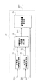
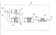
図2は、本発明の実施例1の映像信号処理装置を示すブロック図である。この映像信号処理装置1は、入力映像信号S1を映像信号処理部2でノイズ低減処理、鮮鋭度強調処理、コントラスト強調処理して出力映像信号S2を出力する。映像信号処理装置1は、高域成分計測部3及び高域成分変動特徴量計測部4により、入力映像信号S1に含まれる高域成分量D1及びこの高域成分量D1の周期的な時間変動量を示す高域成分変動特徴量D2をそれぞれ検出する。またこれら高域成分量D1及び高域成分変動特徴量D2により映像信号処理部2における映像信号処理を制御し、これによりフリッカ劣化を低減して入力映像信号S1をノイズ低減処理、鮮鋭度強調処理、コントラスト強調処理する。
(1) Configuration of Embodiment FIG. 2 is a block diagram showing a video signal processing apparatus according to
この実施例において、映像信号処理装置1は、所定のプログラムの実行により入力映像信号S1を処理するプロセッサにより構成され、この実施例ではこのプログラムが事前にインストールされて提供されるものの、これに代えて光ディスク、磁気ディスク、メモリカード等の記録媒体に記録して提供するようにしてもよく、インターネット等のネットワークを介したダウンロードにより提供するようにしてもよい。
In this embodiment, the video
映像信号処理装置1において、高域成分計測部3は、入力映像信号S1から高域成分を分離し、この分離した高域成分の高域成分量D1を検出して出力する。なおここでこの高域成分は、入力映像信号S1の画像空間方向の高域成分としてもよく、また入力映像信号の時間方向の高域成分としてもよい。また高域成分量D1の検出単位は、フィールド単位、フレーム単位の何れとしてもよい。この実施例において、高域成分計測部3は、高域成分量D1の検出単位がフレーム単位に設定され、画像空間方向に高域成分を分離して高域成分量D1を検出する。これにより高域成分計測部3は、例えば2次元のハイパスフィルタにより入力映像信号S1から高域成分を分離した後、フレーム単位で高域成分の絶対値和、2乗和等を求め、高域成分量D1を検出する。またこの2次元のハイパスフィルタの設定により、1種類の特定の性質をもつ高域成分を抽出し、この実施例では、この1種類の特定の性質をもつ高域成分が時間軸方向にランダムに発生する性質を有するランダムノイズ成分に設定される。なお時間軸方向に高域成分を分離する場合には、入力映像信号S1のフィールド間差分、又はフレーム間差分を求めることにより、高域成分を分離することができる。またランダムノイズ成分に代えてテクスチャ、明るさの情報をこの特定の性質に適用するようにしてもよく、テクスチャを適用する場合には、画素値の分散値に応じて検出した高域成分量D1を増減して出力することが考えられる。また明るさの情報を含ませる場合には、検出した高域成分量D1を輝度値により増減して出力することが考えられる。
In the video
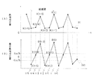
ここで入力映像信号S1がMPEGにより伝送された映像信号である場合、図3に示すように、高域成分計測部3で検出される高域成分量D1は、入力映像信号S1に設定されていたピクチャータイプに応じて変化することになる。なおここでこの図3では、Iピクチャー、Pピクチャー、Bピクチャーをそれぞれ符号I、P、Bで示す。従ってこの図3では、1GOPを15フレームにより構成し、GOPの先頭ピクチャーをIピクチャーに、先頭から3n+1番目のピクチャーをPピクチャーに設定し、残りをBピクチャーに設定した場合である。但しnは、整数である。
Here, when the input video signal S1 is a video signal transmitted by MPEG, as shown in FIG. 3, the high frequency component amount D1 detected by the high frequency
MPEGにより伝送された映像信号では、エンコード時の符号量の割り当て量、両方向予測における内挿予測の選択率の高さ等により、一般的に、Bピクチャーで高域成分量が減少する。またIピクチャーでは、符号割り当て量が多いことにより、相対的に高域成分量が増大し、Pピクチャーでは、高域成分量がIピクチャー及びBピクチャーの中間値となる。なおこのような各ピクチャーにおける高域成分量は、エンコード時のレート制御等によって変化するものの、この高域成分量の時間変動がフリッカ劣化の原因であり、入力映像信号S1に設定されていたピクチャータイプに応じて周期的に発生することになる。 In a video signal transmitted by MPEG, a high frequency component amount generally decreases in a B picture due to a code amount allocation amount at the time of encoding, a high selection rate of interpolation prediction in bidirectional prediction, and the like. Also, in the I picture, since the code allocation amount is large, the high frequency component amount relatively increases, and in the P picture, the high frequency component amount becomes an intermediate value between the I picture and the B picture. Although the high frequency component amount in each picture varies depending on the rate control at the time of encoding, the temporal variation of the high frequency component amount is a cause of flicker degradation, and the picture set in the input video signal S1. It will occur periodically depending on the type.
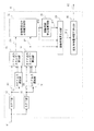
高域成分変動特徴量計測部4は、この高域成分量D1の周期的な時間変動量を検出する。ここで図1は、高域成分変動特徴量計測部4を示すブロック図である。この高域成分変動特徴量計測部4において、バンドパスフィルタ(BPF)部11は、入力映像信号S1に設定されていたピクチャータイプの周期パターンに対応して、入力映像信号S1のBピクチャーと非Bピクチャーの周期性に対応する周波数成分を抽出して出力する。具体的にバンドパスフィルタ部11は、入力映像信号S1のGOP構造が図3に示すGOP構造の場合、図4に示すように、タップ係数が値2、−1、−1による3タップのFIRフィルタにより、I及びPピクチャーの繰り返し周期である3フレーム周期の周期変動成分を高域成分量D1から抽出する。なおこの場合、図4との対比により図5に示すように、タップ数を3タップ以上の例えば6タップとして、バンドパスフィルタ部11をさらに狭帯域化してもよい。また図4及び図5との対比により図6に示すようにタップ係数を設定して、IピクチャーとPピクチャーの高域成分量D1の違いを抽出結果に反映させるようにしてもよい。
The high frequency component fluctuation feature
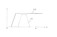
ハイパスフィルタ(HPF)部12は、図7に示すように、バンドパスフィルタ部11の通過帯域L11を含む周波数帯域が通過帯域に設定され、高域成分量D1から当該通過帯域の信号成分を抽出して出力信号D4を出力する。ここで図8は、ハイパスフィルタ部12の構成を示すブロック図である。ハイパスフィルタ部12において、平均値フィルタ部14は、バンドパスフィルタ部11と同一のタップ長を有する平均値フィルタであり、高域成分量D1を平均値化して高域成分量D1のDC値を出力する。従って平均値フィルタ部14は、例えばバンドパスフィルタ部11を図5に示す特性により6タップで構成した場合、タップ係数が値1、1、1、1、1、1の平均値フィルタが適用される。
As shown in FIG. 7, the high-pass filter (HPF)
ハイパスフィルタ部12は、この平均値フィルタ部14の出力信号を高域成分量D1から減算して出力信号D4を出力する。なおハイパスフィルタ部12は、この図8に示す構成に限らず、種々の構成を広く適用することができる。
The high
バンドパスフィルタ(BPF)出力遅延部16は、バンドパスフィルタ部11の出力信号D3を1サンプリング周期ずつ順次遅延させて複数系統により出力する。ハイパスフィルタ(HPF)出力遅延部17は、バンドパスフィルタ出力遅延部16と同一に、ハイパスフィルタ部12の出力信号D4を一定時間ずつ順次遅延させて複数系統により出力する。これによりバンドパスフィルタ出力遅延部16、ハイパスフィルタ出力遅延部17は、最大の遅延時間で決まる一定期間内で、バンドパスフィルタ部11、ハイパスフィルタ部12から出力される複数の出力信号D3、出力信号D4をそれぞれ同時並列的に出力する。
The bandpass filter (BPF)
バンドパスフィルタ(BPF)出力エネルギー算出部18は、バンドパスフィルタ出力遅延部16から出力される複数系統の出力信号D3、バンドパスフィルタ部11から出力される出力信号D3を入力し、これらの出力信号D3のエネルギー値を算出する。なおこのエネルギーの算出は、例えば2乗和、2乗和の平方根、絶対値和等、種々の算出方法を適用することができる。
The bandpass filter (BPF) output
ハイパスフィルタ(HPF)出力エネルギー算出部19は、ハイパスフィルタ出力遅延部17から出力される複数系統の出力信号D4、ハイパスフィルタ部12から出力される出力信号D4を入力し、バンドパスフィルタ出力エネルギー算出部18と同様に、これらの出力信号D4のエネルギー値を算出する。
A high-pass filter (HPF) output
変動周期成分占有度算出部20は、バンドパスフィルタ出力エネルギー算出部18で算出されたエネルギー値D7を、ハイパスフィルタ出力エネルギー算出部19で算出されたエネルギー値D9で割り算し、これにより入力映像信号S1の高域成分に占める周期変動成分の割合である変動周期成分占有度D10を検出する。従ってこの場合、変動周期成分占有度D10の値が大きい程、入力映像信号S1は、ピクチャータイプによる高域成分の周期変動成分の占める割合が大きいことになる。
The fluctuation period component
変動周期安定度算出部21は、変動周期成分占有度算出部20で算出された変動周期成分占有度D10を入力し、図9(A)及び(B)に示すように、この変動周期成分占有度D10の時間軸方向の安定度を示す変動周期安定度D11を計算する。なおここでこの変動周期安定度D11は、変動周期成分占有度D10の分散値、標準偏差、平均偏差等を計算して求めることができる。ここで図9に示す例では、期間Tの間、変動周期成分占有度D10の変化が他の期間に比して小さく、変動周期安定度D11がこの期間Tで増大していることが判る。
The fluctuation cycle
変動特徴量生成部23は、バンドパスフィルタ出力エネルギー算出部18で算出されたエネルギー値D7を変動周期成分占有度D10、変動周期安定度D11で補正し、入力映像信号S1に設定されていたピクチャータイプによる高域成分の周期変動成分の大きさを示す変動特徴量D12を出力する。
The variation feature
ここで図10は、変動特徴量生成部23の詳細構成を示すブロック図である。変動特徴量生成部23において、占有度信頼度設定部25は、変動周期成分占有度D10を所定の閾値Rth1、Rth2で判定し、図11に示すように、変動周期成分占有度D10が閾値Rth1以下の場合には値0であり、変動周期成分占有度D10が閾値Rth2以上の場合には値1であり、変動周期成分占有度D10が閾値Rth1以上、閾値Rth2以下の場合には、変動周期成分占有度D10の増大により直線的に値が増大するように、占有度信頼度D13を生成する。ここで占有度信頼度D13は、変動周期成分占有度D10が、ピクチャータイプによる周期変動を反映している確からしさを示すパラメータである。
Here, FIG. 10 is a block diagram showing a detailed configuration of the fluctuation feature
安定度信頼度設定部26は、変動周期安定度D11を所定の閾値Sth1、Sth2で判定し、図12に示すように、変動周期安定度D11が閾値Sth1以下の場合には値0であり、変動周期安定度D11が閾値Sth2以上の場合には値1であり、変動周期安定度D11が閾値Sth1以上、閾値Sth2以下の場合には、変動周期安定度D11の増大により直線的に値が増大するように、安定度信頼度D14を生成する。ここで安定度信頼度D14は、変動周期安定度D11が、ピクチャータイプによる周期変動を反映している確からしさを示すパラメータである。
The stability
変動特徴信頼度設定部27は、占有度信頼度D13と安定度信頼度D14とを乗算し、バンドパスフィルタ出力エネルギー算出部18で算出されたエネルギー値D7がピクチャータイプによる周期変動を反映している確からしさである変動特徴信頼度D15を算出する。
The variation feature
変動特徴量算出部28は、この変動特徴信頼度D15を所定の閾値で判定し、この判定結果に基づいて、変動特徴信頼度D15がこの閾値以上の場合、バンドパスフィルタ出力エネルギー算出部18で算出されたエネルギー値D7をそのまま変動特徴量D12として出力する。これに対して変動特徴信頼度D15がこの閾値より小さい場合、変動特徴量D12を値0に設定して出力する。
The variation feature
これらの処理により高域成分変動特徴量計測部4は、ピクチャータイプによる周期変動に係る特定周波数への集中度とその時間的安定性とを評価して信頼度D13、D14を生成し、この信頼度D13、D14に基づいて、高域成分量D1の周期変動成分の大きさを示す変動特徴量D12を生成する。
Through these processes, the high-frequency component variation feature
変動特徴量時間平滑化部30(図1)は、変動特徴量生成部23で検出した変動特徴量D12を平滑化処理し、高域成分変動特徴量D2を出力する。なお平滑化処理は、IIRフィルタ構成又はFIRフィルタ構成のローパスフィルタ、メディアンフィルタ等を適用することができる。
The variation feature amount time smoothing unit 30 (FIG. 1) smoothes the variation feature amount D12 detected by the variation feature
図13は、映像信号処理部2を示すブロック図である。映像信号処理部2において、ノイズ低減処理部32は、入力映像信号S1に含まれる画像空間方向及び時間軸方向のランダムノイズ成分を抑圧することにより、入力映像信号S1のノイズを抑圧して出力する。鮮鋭度強調処理部33は、このノイズ低減処理部32から出力される映像信号S3の特定周波数成分を強調することにより、入力映像信号S1の鮮鋭度を強調して出力する。続くコントラスト強調処理部34は、この鮮鋭度強調処理部33から出力される映像信号S4の画面内の輝度分布に応じてコントラストを強調して出力する。具体的に、コントラスト強調処理部34は、図14において符号L34で示すように、非線型な特性により入力映像信号S1を増幅してコントラストを強調し、この非線型な特性を画面内平均輝度レベル、輝度ヒストグラム等に基づいて動的に変化させる。なお図14は、中間階調を強調する非線型な特性であり、この場合、入力映像信号S1の信号レベルが高い側及び低い側では増幅率が低下し、その分、中間階調の増幅率が増大するように設定される。コントラスト強調処理部34は、暗部の階調を強調する場合には、入力映像信号S1の信号レベルが低い側で増幅率を増大させ、その分、中間階調及び高階調で増幅率を低下させる。この実施例の映像信号処理装置1は、このコントラスト強調処理部34でコントラストを強調した映像信号を出力映像信号S2により出力する。
FIG. 13 is a block diagram showing the video
なお映像信号の処理にあっては、これらノイズ低減処理、鮮鋭度強調処理、コントラスト強調処理の何れか1つ、又は2つの処理を実行するようにしてもよく、さらには他の処理と組み合わせて実行するようにしてもよい。また処理の順番を入れ代えるようにしてもよく、さらには同時並列的にこれらの処理を実行して、その結果得られる複数系統の映像信号を合成して出力映像信号S2としてもよい。 In the video signal processing, any one or two of these noise reduction processing, sharpness enhancement processing, and contrast enhancement processing may be executed, and further combined with other processing. You may make it perform. Further, the order of the processes may be changed, and further, these processes may be executed simultaneously and in parallel, and a plurality of video signals obtained as a result may be synthesized to be the output video signal S2.
制御情報生成部35は、高域成分量D1及び高域成分変動特徴量D2に基づいて、ノイズ低減処理部32、鮮鋭度強調処理部33、コントラスト強調処理部34の動作をそれぞれ制御する制御情報D16、D17、D18を出力する。
The control information generation unit 35 controls the operations of the noise
ここで高域成分計測部3で検出される高域成分量D1は、ランダムノイズの性質を有する成分を検出していることになる。これにより制御情報生成部35は、高域成分量D1の値が増大するに従ってノイズ抑圧効果が増大するようにノイズ低減処理部32を制御し、これにより出力信号S3に含まれるノイズ成分を時間軸方向に均一化して入力映像信号S1のノイズを低減する。またこのノイズ成分の時間軸方向に均一化によりこの実施例では、併せてフリッカ劣化に係る高域成分の時間変動についても時間軸方向に均一化する。
Here, the high-frequency component amount D1 detected by the high-frequency
これに対して高域成分変動特徴量D2が大きな値を示している場合、ピクチャータイプによる高域成分量の周期的な時間変動が発生しており、かつ、その変動幅が大きいことを示していることになる。これにより制御情報生成部35は、高域成分変動特徴量D2の値を所定の閾値で判定し、高域成分変動特徴量D2の値がこの閾値より大きい場合、ノイズ低減効果が通常より増大するように、ノイズ低減処理部32を制御する。なおこの閾値以上の場合に、高域成分変動特徴量D2の増大により徐々にノイズ低減効果が増大するように設定してもよく、また高域成分変動特徴量D2の増大により段階的にノイズ低減効果が増大するように設定してもよい。また閾値以上の場合と、閾値未満の場合とで、2段階でノイズ低減効果を切り換えるようにしてもよい。
On the other hand, when the high frequency component variation feature amount D2 shows a large value, it indicates that the temporal variation of the high frequency component amount due to the picture type has occurred and the variation range is large. Will be. As a result, the control information generation unit 35 determines the value of the high-frequency component variation feature value D2 with a predetermined threshold value, and when the value of the high-frequency component variation feature value D2 is larger than this threshold value, the noise reduction effect increases more than usual. Thus, the noise
これにより制御情報生成部35は、高域成分量D1に従って時間軸方向のノイズ成分の変動を抑圧するようにして、高域成分変動特徴量D2によりこの時間軸方向にノイズ成分を抑圧する程度を可変し、フリッカ劣化を低減してノイズ成分を抑圧する。 Thereby, the control information generation unit 35 suppresses the fluctuation of the noise component in the time axis direction according to the high frequency component amount D1, and suppresses the noise component in the time axis direction by the high frequency component fluctuation feature amount D2. Variable, reduces flicker degradation and suppresses noise components.
これに対して鮮鋭度強調処理部33における鮮鋭度強調処理は、特定周波数成分を強調して鮮鋭度を強調する処理であることから、制御情報生成部35は、高域成分量D1の値が増大するに従ってこの鮮鋭度の強調に係る特定周波数帯域の増幅率が低下するように鮮鋭度強調処理部33を制御し、これにより出力信号S4に含まれる高域成分を時間軸方向に均一化する。また制御情報生成部35は、高域成分変動特徴量D2の値を所定の閾値で判定し、高域成分変動特徴量D2の値がこの閾値より大きい場合、この鮮鋭度の強調に係る特定周波数帯域の増幅率が低下するように、鮮鋭度強調処理部33を制御する。なおこの閾値以上の場合に、高域成分変動特徴量D2の増大により徐々に増幅率が低下するように設定してもよく、また高域成分変動特徴量D2の増大により段階的に増幅率が低下するように設定してもよい。また閾値以上の場合と、閾値未満の場合とで、2段階で増幅率を切り換えるようにしてもよい。これにより制御情報生成部35は、鮮鋭度強調処理部33の出力信号S4に含まれる高域成分量の周期的な時間変動の幅を小さくして、フリッカ劣化を低減する。
On the other hand, the sharpness enhancement processing in the sharpness
また制御情報生成部35は、高域成分変動特徴量D2の値を所定の閾値で判定し、高域成分変動特徴量D2の値がこの閾値より大きい場合、高域成分変動特徴量D2の増大に従って、コントラスト強調に係る非線型な特性を弱めて、図14において符号L34Aにより示す線型な特性に近づくように、コントラスト強調処理部34を制御する。なおこの閾値以上の場合にも、高域成分変動特徴量D2の増大により徐々に線型な特性に近づくように設定してもよく、また高域成分変動特徴量D2の増大により段階的に線型な特性に近づくように設定してもよい。また閾値以上の場合と、閾値未満の場合とで、2段階で特性を切り換えるようにしてもよい。これにより制御情報生成部35は、出力映像信号S2におけるフリッカ劣化を低減する。
Further, the control information generation unit 35 determines the value of the high-frequency component variation feature value D2 with a predetermined threshold, and when the value of the high-frequency component variation feature value D2 is larger than the threshold value, the increase of the high-frequency component variation feature value D2 Accordingly, the non-linear characteristic related to contrast enhancement is weakened, and the contrast
なおこれによりこの実施例では、ノイズ低減処理部32、鮮鋭度強調処理部33、コントラスト強調処理部34における入力映像信号S1の映像信号処理のうちで、コントラスト強調処理部34におけるコントラスト強調処理のみ、入力映像信号S1に応じて特性を切り換え、さらには非線型な特性で入力映像信号S1を処理する場合について述べたが、本発明はこれに限らず、ノイズ低減処理部32及び鮮鋭度強調処理部33における処理についても、入力映像信号S1に応じて特性を切り換え、さらには非線型な特性で入力映像信号S1を処理する場合に広く適用することができる。なおノイズ低減処理部32等のようにこのように固定した特性で入力映像信号S1を処理する場合にあっても、フリッカ劣化を低減できることは言うまでも無い。
In this way, in this embodiment, among the video signal processing of the input video signal S1 in the noise
(2)実施例の動作
以上の構成において、入力映像信号S1は(図2)、映像信号処理部2によりノイズ低減処理、鮮鋭度強調処理、コントラスト強調処理されて画質が向上され、出力映像信号S2により出力される。ここでこれらノイズ低減処理、鮮鋭度強調処理、コントラスト強調処理は、入力映像信号S1の高域成分に対する処理であることから、入力映像信号S1がMPEG等によりデータ圧縮されて伝送された映像信号である場合、この入力映像信号S1に設定されていたピクチャータイプによる高域成分の周期的な変動(図3)が出力映像信号S2を表示した際にフリッカ劣化として知覚されるようになる。
(2) Operation of Embodiment In the above configuration, the input video signal S1 (FIG. 2) is subjected to noise reduction processing, sharpness enhancement processing, and contrast enhancement processing by the video
そこで映像信号処理装置1において、入力映像信号S1は、高域成分計測部3において、高域成分量D1が検出され、続く高域成分変動特徴量計測部4で高域成分量D1が処理されてこの高域成分量D1の周期的な時間変動量を示す高域成分変動特徴量D2が検出される。またこの高域成分量D1によりノイズ低減処理の時間軸方向の変動を抑圧するようにして、高域成分変動特徴量D2により、出力映像信号S2の高域成分における周期的な変動を抑圧するように、ノイズ低減処理、鮮鋭度強調処理、コントラスト強調処理が可変制御される。これによりこの映像信号処理装置では、フリッカ劣化に係る高域成分の周期的な変動の大きさに応じて映像信号処理の特性を変化させてフリッカ劣化が目立たないようにすることができ、従来に比してフリッカ劣化を低減することができる。また特性の可変により出力映像信号S2の高域成分における周期的な変動を抑圧することにより、映像信号処理の特性を入力映像信号S1に応じて適応的に可変する場合にあっても、確実にフリッカ劣化を低減することができる。
Therefore, in the video
すなわち入力映像信号S1は、高域成分計測部3において、画像空間方向の高域成分及び又は時間方向の高域成分が分離されて高域成分量が検出され、これにより必要に応じて画像空間方向の高域成分及び又は時間方向の高域成分により高域成分量を検出して、確実にフリッカ劣化を低減することができる。またノイズ抑圧処理にこの高域成分量を利用してノイズ抑圧効果を制御することができ、全体構成を簡略化することができる。すなわち画像空間方向の高域成分によれば、例えば高域成分量の検出単位をフレームに設定して、1画面内の各所で高域成分の成分量が変化する場合でも、フリッカ劣化の要因となる高域成分の成分量を確実に検出することができる。また時間方向の高域成分によれば、高域成分の成分量が時間変動する場合でも、フリッカ劣化の要因となる高域成分の成分量を確実に検出することができる。
That is, the input video signal S1 is detected by the high frequency
またさらにこの高域成分計測部3における処理において、時間方向に特定の性質を有する画像空間方向の高域成分を分離して高域成分量を検出することにより、画像空間方向及び時間方向で高域成分量を検出したと同様にして高域成分量を検出することができ、これにより全体構成を簡略化して確実にフリッカ劣化の要因となる高域成分の成分量を検出することができる。またこの時間方向に特定の性質にランダムノイズの性質を適用することにより、ノイズ抑圧処理にこの高域成分量を利用して全体構成を簡略化することができる。
Further, in the processing in the high frequency
これに対して高域成分変動特徴量計測部4において、入力映像信号S1は、高域成分量D1がバンドパスフィルタ部11に入力され(図1)、ここで入力映像信号S1に設定されていたピクチャータイプの周期パターンに対応する、Bピクチャー及び非Bピクチャーの繰り返し周期成分が抽出される(図4〜図6)。またこの繰り返し周期成分により高域成分変動特徴量D2が生成される。これによりこの映像信号処理装置1では、GOP構造に由来するフリッカ劣化を確実に低減することが可能となる。
On the other hand, in the high-frequency component variation feature
より具体的に、入力映像信号S1は、このバンドパスフィルタ部11の通過帯域を含むように通過帯域が設定されたハイパスフィルタ部12により高域成分量D1の高域成分が検出され(図7及び図8)、入力映像信号S1の高域成分に占める周期変動成分の割合を検出することが可能とされる。入力映像信号は、これによりバンドパスフィルタ部11の出力信号に基づいてハイパスフィルタ部12の出力信号により補正するように、これらの出力信号を処理して高域成分変動特徴量D2が生成される。これによりこの映像信号処理装置1では、例えば入力映像信号S1に本来的に含まれる高域成分の多少により、フリッカ劣化の低減処理を誤動作させないようにすることができ、これにより確実にフリッカ劣化を低減することが可能となる。
More specifically, the high frequency component of the high frequency component amount D1 is detected in the input video signal S1 by the high
すなわち映像信号処理装置1では、バンドパスフィルタ部11の出力信号及びハイパスフィルタ部12の出力信号のエネルギー値D7及びD9がそれぞれバンドパスフィルタ出力エネルギー算出部18及びハイパスフィルタ出力エネルギー算出部19で求められ、このエネルギー値D7がエネルギー値D9で割り算されて、入力映像信号S1の高域成分に占める周期変動成分の割合である変動周期成分占有度D10が求められる。またこの変動周期成分占有度D10の時間軸方向の安定度を示す変動周期安定度D11が変動周期安定度算出部21で求められる(図9)。またバンドパスフィルタ部11の出力信号のエネルギー値D7を変動周期成分占有度D10及び変動周期安定度D11で補正して高域成分変動特徴量D2が求められる。
That is, in the video
これによりこの映像信号処理装置1では、入力映像信号S1において、ピクチャータイプの周期変動成分と類似した信号レベルの変化が一時的に発生した場合にあっても、さらには入力映像信号S1の高域成分が種々に変化している場合にあっても、フリッカ劣化を確実に抑圧することができる。
As a result, in the video
すなわち入力映像信号S1は、変動周期成分占有度D10及び変動周期安定度D11がそれぞれ所定の閾値Rth1、Rth2及びSth1、Sth2で判定され(図10、図11、図12)、変動周期成分占有度D10及び変動周期安定度D11がそれぞれ極端に小さい場合には、それぞれ信頼度D13、D14が低いと判定される。また変動周期成分占有度D10及び変動周期安定度D11が増大するに従って信頼度D13、D14が上昇して値1で飽和するように設定される。またこれら信頼度D13、D14の乗算値が求められ、これにより総合の信頼度が求められる。 That is, in the input video signal S1, the fluctuation period component occupancy D10 and the fluctuation period stability D11 are determined by the predetermined threshold values Rth1, Rth2, Sth1, and Sth2, respectively (FIGS. 10, 11, and 12). When D10 and fluctuation cycle stability D11 are extremely small, it is determined that the reliability D13 and D14 are low. Further, the reliability D13 and D14 are set to increase and saturate at a value of 1 as the fluctuation cycle component occupancy D10 and the fluctuation cycle stability D11 increase. Further, a multiplication value of the reliability levels D13 and D14 is obtained, thereby obtaining an overall reliability level.
入力映像信号S1は、この総合の信頼度が一定値以上の場合に、バンドパスフィルタ部11の出力信号のエネルギー値D7が変動特徴量D12として出力され、この変動特徴量D12が平滑化処理されて高域成分変動特徴量D2が求められる。
When the total reliability of the input video signal S1 is equal to or greater than a certain value, the energy value D7 of the output signal of the
入力映像信号S1は(図13)、映像信号処理部2のノイズ低減処理部32、鮮鋭度強調処理部33、コントラスト強調処理部34で順次、ノイズ低減処理、鮮鋭度強調処理、コントラスト強調処理されて出力映像信号S2により出力される。またこれらの処理において、コントラスト強調処理では、非線型な特性により増幅されてコントラストが強調され、この非線型な特性が入力映像信号S1の画面内平均輝度レベル、輝度ヒストグラム等に基づいて動的に変化されることにより、入力映像信号S1に応じて非線型な特性を動的に変化させて、入力映像信号S1のコントラストが低減される。
The input video signal S1 (FIG. 13) is sequentially subjected to noise reduction processing, sharpness enhancement processing, and contrast enhancement processing by the noise
これによりこのコントラスト強調処理部34によるコントラスト強調処理については、単に入力映像信号の輝度信号をガンマ補正してフレーム間で平均輝度レベル差を検出し、このレベル差を抑圧するように入力映像信号S1の信号レベルを補正したのでは、フリッカ劣化を低減することが困難になる。
As a result, with respect to the contrast enhancement processing by the contrast
しかしながらこの実施例のように高域成分の周期変動成分を検出してコントラスト強調に係る特性の変更によりこの周期変動成分を抑圧するように設定すれば、非線型な特性により入力映像信号S1を種々に処理する場合でも、フリッカ劣化を確実に低減することができる。 However, if the periodic variation component of the high frequency component is detected and the periodic variation component is set to be suppressed by changing the characteristic related to contrast enhancement as in this embodiment, the input video signal S1 can be variously displayed by nonlinear characteristics. Even in the case of processing the same, flicker degradation can be reliably reduced.
これによりこの実施例では、高域成分量D1の値が増大するに従ってノイズ抑圧効果が増大するようにノイズ低減処理部32を制御し、これにより出力信号S3に含まれるノイズ成分を時間軸方向に均一化するようにして、入力映像信号S1のノイズを低減し、さらにフリッカ劣化に係る高域成分の時間変動を低減する。これによりこの実施例では、ノイズ低減処理に係るノイズ量の計測を、高域成分計測部3で実行するようにして、ノイズ低減処理部32の構成を簡略化する。また高域成分変動特徴量D2の値を所定の閾値で判定し、高域成分変動特徴量D2の値がこの閾値より大きい場合、ノイズ低減効果を通常より増大させ、これによりノイズ低減処理により知覚可能となるフリッカ劣化を低減する。
Thus, in this embodiment, the noise
また高域成分量D1の値が増大するに従って鮮鋭度の強調に係る特定周波数帯域の増幅率が低下するように鮮鋭度強調処理部33を制御し、これにより出力信号S4に含まれる高域成分を時間軸方向に均一化する。また高域成分変動特徴量D2の値を所定の閾値で判定し、高域成分変動特徴量D2の値がこの閾値より大きい場合、この鮮鋭度の強調に係る特定周波数帯域の増幅率が低下するように、鮮鋭度強調処理を制御し、これにより鮮鋭度強調処理により知覚可能となるフリッカ劣化を低減する。
Further, the sharpness
また高域成分変動特徴量D2の値を所定の閾値で判定し、高域成分変動特徴量D2の値がこの閾値より大きい場合、高域成分変動特徴量D2の増大に従って、コントラスト強調に係る非線型な特性を弱めて線型な特性に近づくように、コントラスト強調処理を制御する(図14)。これによりコントラスト強調処理により知覚可能となるフリッカ劣化を低減する。 Further, when the value of the high-frequency component variation feature quantity D2 is determined with a predetermined threshold value and the value of the high-frequency component variation feature value D2 is larger than this threshold value, the non-contrast enhancement is performed according to the increase of the high-frequency component variation feature value D2. The contrast enhancement process is controlled so that the linear characteristic is weakened to approach the linear characteristic (FIG. 14). This reduces flicker degradation that can be perceived by contrast enhancement processing.
(3)実施例の効果
以上の構成によれば、入力映像信号に含まれる高域成分量の周期的な時間変動量を検出し、この検出結果に基づいて、この周期的な時間変動を抑圧するように映像信号処理の特性を可変することにより、従来に比して一段と確実にフリッカ劣化を低減することができる。
(3) Effects of the embodiment According to the above configuration, the periodic time fluctuation amount of the high frequency component amount included in the input video signal is detected, and the periodic time fluctuation is suppressed based on the detection result. Thus, by varying the characteristics of the video signal processing, it is possible to reduce the flicker deterioration more reliably than in the past.
またこの入力映像信号から、画像空間方向の高域成分及び又は時間方向の高域成分を分離して高域成分量を検出することにより、確実にフリッカ劣化を低減することができる。 Further, by detecting the high frequency component amount by separating the high frequency component in the image space direction and / or the high frequency component in the time direction from the input video signal, it is possible to reliably reduce flicker degradation.
また時間方向に特定の性質を有する画像空間方向の高域成分を分離して高域成分量を検出することにより、画像空間方向及び時間方向で高域成分量を検出したと同様にして高域成分量を検出することができ、これにより全体構成を簡略化して確実にフリッカ劣化の要因となる高域成分の成分量を検出することができる。またこの時間方向に特定の性質にランダムノイズの性質を適用することにより、ノイズ抑圧処理にこの高域成分量を利用して全体構成を簡略化することができる。 In addition, by separating the high frequency component in the image space direction having specific properties in the time direction and detecting the high frequency component amount, the high frequency component is detected in the same manner as the high frequency component amount is detected in the image space direction and the time direction. The amount of components can be detected, whereby the overall configuration can be simplified and the amount of high-frequency components that cause flicker degradation can be reliably detected. In addition, by applying the random noise property to the specific property in the time direction, the entire configuration can be simplified by using this high frequency component amount for noise suppression processing.
また入力映像信号に設定されていたピクチャータイプの周期パターンに対応する高域成分量の周期的な時間変動量を検出することにより、GOP構造に由来するフリッカ劣化を確実に低減することができる。 Further, by detecting the periodic temporal fluctuation amount of the high frequency component amount corresponding to the picture type periodic pattern set in the input video signal, it is possible to reliably reduce the flicker deterioration derived from the GOP structure.
また高域成分量からこの周期パターンに対応する信号成分を抽出すると共に、この信号成分を含む高域成分を抽出し、この周期パターンに係る信号成分を抽出した高域成分で補正して高域成分変動特徴量を生成することにより、入力映像信号S1に本来的に含まれる高域成分の多少により、フリッカ劣化の低減処理を誤動作させないようにすることができ、これにより確実にフリッカ劣化を低減することが可能となる。 In addition, a signal component corresponding to this periodic pattern is extracted from the amount of the high frequency component, a high frequency component including this signal component is extracted, and the signal component related to this periodic pattern is corrected with the extracted high frequency component to obtain a high frequency component. By generating the component variation feature amount, it is possible to prevent the malfunction of the flicker degradation reduction process due to the amount of the high frequency component inherently included in the input video signal S1, thereby reliably reducing the flicker degradation. It becomes possible to do.
すなわちバンドパス出力及びハイパス出力による信号成分のエネルギーをそれぞれ算出して比率を求め、この比率である変動周期成分占有度の時間軸方向の安定度を示す変動周期安定度を計算し、バンドパス出力のエネルギー値を、変動周期成分占有度及び変動周期安定度で補正して高域成分変動特徴量を検出することにより、ピクチャータイプの周期変動成分と類似した信号レベルの変化が一時的に発生した場合にあっても、さらには入力映像信号の高域成分が種々に変化している場合にあっても、フリッカ劣化を確実に抑圧することができる。 That is, calculate the ratio by calculating the energy of the signal component due to the bandpass output and the highpass output respectively, calculate the fluctuation period stability indicating the stability of the fluctuation period component occupancy that is this ratio in the time axis direction, and the bandpass output By detecting the high frequency component fluctuation feature quantity by correcting the energy value of the fluctuation period component occupancy and fluctuation period stability, a signal level change similar to that of the picture type periodic fluctuation component occurred temporarily. Even in this case, even when the high frequency component of the input video signal changes variously, it is possible to reliably suppress flicker degradation.
また入力映像信号に応じて特性を可変して、非線型な特性により入力映像信号を増幅してコントラストを強調する場合に、高域成分変動特徴量に基づいて、非線型な特性を線型な特性に近づけて周期的な変動を抑圧することにより、入力映像信号に応じて特性を可変して映像信号のコントラストを強調する場合に、フリッカ劣化を確実に抑圧することができる。 Also, when the characteristics are varied according to the input video signal and the input video signal is amplified by the non-linear characteristics to enhance the contrast, the non-linear characteristics are converted into the linear characteristics based on the high-frequency component variation feature quantity. By suppressing the periodic fluctuations close to, flicker degradation can be reliably suppressed when the characteristics are varied according to the input video signal to enhance the contrast of the video signal.
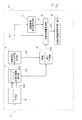
図15は、本発明の実施例2の映像信号処理装置に適用される高域成分変動特徴量計測部の構成を示すブロック図である。この実施例2の映像信号処理装置は、この高域成分変動特徴量計測部44の構成が異なる点を除いて、実施例1の映像信号処理装置1と同一に構成される。また高域成分変動特徴量計測部44は、ハイパスフィルタ部12が省略され、ハイパスフィルタ出力遅延部17、バンドパスフィルタ出力エネルギー算出部18、ハイパスフィルタ出力エネルギー算出部19に代えて高域成分量遅延部46、バンドパスフィルタ(BPF)出力エネルギー算出部48、高域成分エネルギー算出部49が設けられる点を除いて、実施例1の高域成分変動特徴量計測部と同一に構成される。
FIG. 15 is a block diagram illustrating a configuration of a high-frequency component variation feature quantity measurement unit applied to the video signal processing apparatus according to the second embodiment of the present invention. The video signal processing apparatus according to the second embodiment is configured in the same manner as the video
ここで高域成分量遅延部46は、高域成分量D1を直接入力し、バンドパスフィルタ出力遅延部16と同一に、この高域成分量D1を1サンプリング周期ずつ順次遅延させて複数系統により出力する。
Here, the high-frequency component
バンドパスフィルタ出力エネルギー算出部48は、バンドパスフィルタ出力遅延部16から出力される複数系統の出力信号D6、バンドパスフィルタ部11から出力される出力信号D3を入力し、最大値の検出により出力信号D3のエネルギー値D7を算出する。
The band-pass filter output
すなわち図16は、バンドパスフィルタ出力エネルギー算出部48を示すブロック図である。このバンドパスフィルタ出力エネルギー算出部48において、最大値検出部51は、バンドパスフィルタ出力遅延部16から出力される複数系統の出力信号D6、バンドパスフィルタ部11から出力される出力信号D3を入力する。最大値検出部51は、これらの出力信号D6、出力信号D3から最大値D22を検出して出力する。またこの最大値D22が出力信号D3から検出されるタイミングを最大値検出同期信号D21として高域成分エネルギー算出部49に出力する。
That is, FIG. 16 is a block diagram showing the bandpass filter output
すなわち図3について上述したGOP構造を前提に、バンドパスフィルタ部11を図5について上述した6タップにより作成した場合、このバンドパスフィルタ部11のフィルタ係数による基底波形は図17に示すように3フレーム周期で立ち上がることになる。従ってバンドパスフィルタ部11の出力信号D3は、入力映像信号S1にピクチャータイプによる周期変動成分が存在する場合、図18に示すように、この基底波形の繰り返しに対応する信号レベルの変化が発生することになる。
That is, on the premise of the GOP structure described above with reference to FIG. 3, when the
ここでバンドパスフィルタ部11の構成に対応してバンドパスフィルタ出力遅延部16から5系統の出力信号D6を出力する場合、バンドパスフィルタ出力エネルギー算出部48は、時点tのサンプリング値B〔t〕が出力信号D3により入力される時点で、バンドパスフィルタ出力遅延部16からこの時点tの直前の、5つのサンプリング時点t−1、t−2、t−3、t−4、t−5のサンプリング値B〔t−1〕、B〔t−2〕、B〔t−3〕、B〔t−4〕、B〔t−5〕が出力信号D6により入力されることになる。これにより最大値検出部51は、この時点tでは、これら6個のサンプリング値B〔t〕〜B〔t−5〕から最大のサンプリング値B〔t〕を検出して最大値D22を出力する。
Here, when the five output signals D6 are output from the bandpass filter
正規回路エネルギー算出部52は、この最大値検出部51から出力される最大値D22から正規化エネルギー値を検出し、この正規化エネルギー値をバンドパスフィルタ部11から出力される出力信号D3のエネルギー値D7として出力する。ここで正規回路エネルギー算出部52は、バンドパスフィルタ部11のフィルタ係数〔2、−1、−1、2、−1、−1〕による基底ベクトルのノルムで最大値D22を割り算して正規化エネルギー値を計算する。なお基底ベクトルのノルムは、この基底ベクトルの各要素の2乗和の平方根で求められる。
The normal circuit
高域成分エネルギー算出部49は、バンドパスフィルタ出力エネルギー算出部48の処理に対応するように、高域成分量遅延部46から出力される複数系統の出力信号D23、高域成分計測部3から出力される高域成分量D1を処理して高域成分のエネルギー値D9を算出する。
The high frequency component
ここで図19は、この時間ACエネルギー算出部49の構成を示すブロック図である。時間ACエネルギー算出部49において、同期データ検出部54は、最大値検出同期信号D21を基準にして、バンドパスフィルタ部11の出力信号D3で最大値が検出されるタイミングで、高域成分量遅延部46から出力される複数系統の出力信号D23、高域成分計測部3から出力される高域成分量D1を取得して出力する。これにより同期データ検出部54は、図18(A)の例では、サンプリング値R〔t〕〜R〔t−5〕を出力する。
Here, FIG. 19 is a block diagram showing a configuration of the time AC
正規化平均値フィルタ部55は、同期データ検出部54の出力データD24を入力し、この出力データD24に対し、正規化された平均値化を行う。ここで正規化の処理は、同一のフィルタ係数を要素とする基底ベクトルのノルムで出力データD24をそれぞれ割り算して実行される。これによりこの実施例では、6個のサンプリング値R〔t〕〜R〔t−5〕をそれぞれ61/2で割り算して正規化の処理を実行する。正規化平均値フィルタ部55は、この正規化したサンプリング値を合計し、これにより高域成分量D1のDC値を検出して出力する。
The normalized average
高域成分量時間DCエネルギー算出部56は、正規化平均値フィルタ部55の出力データD25の2乗値を求めて出力する。高域成分量時間エネルギー算出部57は、同期データ検出部54の出力データD24(R〔t〕〜R〔t−5〕)の2乗値を計算し、これにより高域成分量D1の時間方向のエネルギー値D27を出力する。
The high frequency component amount time DC
減算回路58は、高域成分量時間エネルギー算出部57の出力データD27から高域成分量時間DCエネルギー算出部56の出力データD26を減算し、高域成分量D1のAC成分のエネルギー値D9を算出する。
The
これにより高域成分変動特徴量計測部44は、特定期間内におけるバンドパスフィルタから最大値のエネルギーを正規化して検出すると共に、この最大値のタイミングを基準にして高域成分量の時間DCエネルギーを正規化して求め、正規化した最大値の時間DCエネルギーを正規化した高域成分の時間エネルギーから減算して高域成分量の時間AC成分のエネルギー値D9を出力する。
As a result, the high-frequency component variation feature
ここで図20に示すように、正規直交座標空間上でこれらのエネルギーを表すこととする。なおここでこの正規直交座標空間は、バンドパスフィルタ部11、正規化平均値フィルタ部55に使用されるフィルタのタップ数が6であることから、6次元空間である。バンドパスフィルタ部11、正規化平均値フィルタ部55の入力である高域成分量D1を、この正規直交座標空間上において、連続する6個のサンプリング値をそれぞれ要素とする6次元のベクトルYで表す。この場合、正規化平均値フィルタ部55の出力信号D25は、このベクトルYをDC軸に投影したベクトルXDCのノルムとなり、この出力信号D25を高域成分量時間DCエネルギー算出部56で処理して得られるエネルギー値D26は、このベクトルXDCのノルムの2乗値に相当することになる。これに対して高域成分量時間エネルギー算出部57から出力されるエネルギー値D27は、6次元のベクトルYのノルムの2乗値に相当することになる。
Here, as shown in FIG. 20, it is assumed that these energies are expressed in an orthonormal coordinate space. Here, the orthonormal coordinate space is a six-dimensional space because the number of filter taps used in the
またバンドパスフィルタ出力エネルギー算出部18で求められるエネルギー値D7は、バンドパスフィルタ部11を構成するフィルタの係数を要素とするベクトル方向の軸に、ベクトルYを射影したベクトルXBPのノルムの2乗値に相当することになる。これに対して高域成分量時間エネルギー算出部57のエネルギー値D27から高域成分量時間DCエネルギー算出部56のエネルギー値D26を減算して得られるエネルギー値D9は、ベクトルXDCに垂直な平面上にベクトルYを射影したベクトルXACのノルムの2乗値に相当することになる。なおここでこの図20におけるベクトルXETC は、ベクトルXBP以外のAC成分を示し、残りのAC成分に相当する4つのベクトルの合成ベクトルとして見なすことができる。
Further, the energy value D7 obtained by the bandpass filter output
これによりベクトルXBPのノルムとベクトルXACのノルムとの比、又はこの比の2乗値を算出することにより、実施例1と同様に、変動周期成分占有度D10を検出できることが判る。 Thus the ratio of the norm and the vector X AC of the norm of the vector X BP, or by calculating the square value of this ratio, in the same manner as in Example 1, it can be seen that can detect variation period component occupancy D10.
この映像信号処理装置は、変動周期成分占有度算出部50において、実施例1について上述したと同一に、エネルギー値D7をエネルギー値D9で割り算して変動周期成分占有度D10を検出する。
In this video signal processing apparatus, the fluctuation period component
これによりこの実施例では、高域成分量D1をベクトルにより表現して基底ベクトルにより正規化してエネルギー値を求め、入力映像信号に含まれる高域成分量の周期的な時間変動量を検出することにより、実施例1と同様の効果を得ることができる。 Thereby, in this embodiment, the high frequency component amount D1 is expressed by a vector, normalized by a base vector to obtain an energy value, and a periodic time variation amount of the high frequency component amount included in the input video signal is detected. Thus, the same effect as in the first embodiment can be obtained.
またハイパスフィルタ部12を省略して、高域成分計測部で求められた高域成分量を直接処理して高域成分変動特徴量を検出することにより、簡易な構成で実施例1と同様の効果を得ることができる。
Further, by omitting the high-
図21は、本発明の実施例3の映像信号処理装置に適用される高域成分変動特徴量計測部の構成を示すブロック図である。この実施例3の映像信号処理装置は、この高域成分変動特徴量計測部64の構成が異なる点を除いて、実施例1の映像信号処理装置1と同一に構成される。
FIG. 21 is a block diagram illustrating a configuration of a high-frequency component variation feature amount measurement unit applied to the video signal processing device according to the third embodiment of the present invention. The video signal processing apparatus according to the third embodiment is configured in the same manner as the video
この高域成分変動特徴量計測部64において、AC成分ベクトル成分部65は、高域成分量D1の時間変動成分をベクトル化して出力する。すなわち図22に示すように、AC成分ベクトル生成部65において、高域成分量遅延部66は、高域成分量D1を順次遅延させて、後段の正規化平均値フィルタ部67の入力タップ数より値1だけ少ない複数系統により出力する。
In the high frequency component variation feature
ベクトルデータ生成部68は、高域成分量遅延部66の出力データD23、高域成分量D1を入力し、これら出力データD23、高域成分量D1をそれぞれ要素とするベクトルデータDV1を生成して出力する。従ってこのベクトルデータDV1は、続く正規化平均値フィルタ部67の入力タップ数と同一数の次元を有するベクトルデータであり、高域成分量D1の連続するサンプリング値による信号波形を示すことになる。
The vector
正規化平均値フィルタ部67は、全てのフィルタ係数が同一であって、フィルタ係数を要素とするベクトルの大きさが1となるように係数が設定されたフィルタにより、ベクトルデータ生成部68から出力されるベクトルデータDV1を畳み込み演算し、演算結果D25を出力する。なおここで演算結果D25は、ベクトルデータDV1とこの正規化平均値フィルタ部67のフィルタ係数からなるベクトルとの内積演算結果と等価である。これにより正規化平均値フィルタ部67は、高域成分量D1のDC値D25を検出する。
The normalized average
DC成分ベクトル生成部69は、正規化平均値フィルタ部67のフィルタ係数からなるベクトルを、正規化平均値フィルタ部67から出力される演算結果D25でスケーリングし、高域成分量D1のDC値D25をベクトルデータDV1に対応するDC成分ベクトルDV3により出力する。
The DC component
減算回路70は、ベクトルデータ生成部68から出力されるベクトルデータDV1からDC成分ベクトルDV3を減算し、高域成分量D1の時間変動成分をベクトル化したAC成分ベクトルDV4を出力する。なおここで図20の正規直交座標空間上で、ベクトルデータDV1、DC成分ベクトルDV3、AC成分ベクトルDV4は、それぞれベクトルY、ベクトルXDC、ベクトルXACに対応する。
The
バンドパスベクトル位相相関度算出部73(図21)は、このAC成分ベクトルDV4を処理して、フリッカ劣化に係る高域成分量D1の周期的な時間変動の大きさを示す正規化バンドパス内積信号D32、高域成分量D1の全時間変動成分に対するこの周期的な時間変動成分の大きさを表すバンドパスベクトル位相相関度D34を検出する。 The band-pass vector phase correlation calculating unit 73 (FIG. 21) processes the AC component vector DV4 to indicate a normalized band-pass inner product indicating the magnitude of periodic time fluctuation of the high-frequency component amount D1 related to flicker degradation. A band pass vector phase correlation degree D34 representing the magnitude of this periodic time fluctuation component with respect to all the time fluctuation components of the signal D32 and the high frequency component amount D1 is detected.
すなわち図23に示すように、バンドパスベクトル位相相関度算出部73において、正規化バンドパスベクトル内積演算部75は、正規化されたバンドパスベクトルEBPとAC成分ベクトルDV4(XAC)とを内積演算する。ここで正規化されたバンドパスベクトルEBPは、フリッカ劣化に係る高域成分量D1の周期的な時間変動をモデル化して設定されたバンドパスフィルタのフィルタ係数に対して、タップ係数がAC成分ベクトルDV4の次元数と同じで、かつフィルタ係数を要素とするベクトルの大きさが1となるように正規化されたベクトルである。なおこのフリッカ劣化に係る高域成分量D1の周期的な時間変動をモデル化して設定されたバンドパスフィルタは、例えば図1におけるバンドパスフィルタ部11である。これによりバンドパスベクトル位相相関度算出部73は、内積演算により得られる内積値によりフリッカ劣化に係る高域成分量D1の周期的な時間変動の大きさを検出し、正規化バンドパス内積信号D32として出力する。
That is, as shown in FIG. 23, in the bandpass vector phase
AC成分ベクトルノルム算出部76では、AC成分ベクトルDV4のノルムD33を算出して出力する。
The AC component vector
ベクトル位相相関度算出部77は、次式により示す演算処理により、バンドパスベクトル位相相関度D34(cos θ)を検出する。なおここで<XAC,EBP>は、正規化バンドパス内積信号D32であり、XACの絶対値は、AC成分ベクトルDV4のノルムD33である。
The vector phase correlation

ここで図24に示すように、正規直交座標空間上において、バンドパスベクトルEBPは、EBP=XAC/|XAC|で表されることから、高域成分量D1においてフリッカ劣化に係る周期変動成分が増大して、AC成分ベクトルDV4(XAC)とバンドパスベクトルEBPとの成す角度θが小さくなればなる程、(1)式によるバンドパスベクトル位相相関度D34は値が大きくなる。すなわちバンドパスベクトル位相相関度D34が大きい程、高域成分量D1の時間変動を示しているAC成分ベクトルDV4の向きは、周期的な時間変動を示すバンドパスベクトルと近い方向を指すことになる。なおこの(1)式中の<XAC,EBP>は、|XAC||EBP|cos θ=|XAC|cos θ=|XBP|となり、正規化バンドパス内積信号D32<XAC,EBP>は、図24に示す正規直交空間上において、正規化されたバンドパスベクトルEBPの方向の軸に、ベクトルYを射影したベクトルXBPのノルムであることがわかる。従って、cos θ=|XBP|/|XAC|であり、上述の実施例2で検出した周期変動成分の指標を同様に検出していることが判る。 Here, as shown in FIG. 24, in the orthonormal coordinate space, the bandpass vector E BP is expressed by E BP = X AC / | X AC |. increasing period fluctuation component, as the angle between AC component vector DV4 and (X AC) and band-pass vector E BP theta is the smaller, (1) a band-pass vector phase correlation according to equation D34 value is greater Become. That is, as the bandpass vector phase correlation degree D34 is larger, the direction of the AC component vector DV4 indicating the time variation of the high frequency component amount D1 is closer to the bandpass vector indicating the periodic time variation. . Note that <X AC , E BP > in the equation (1) becomes | X AC || E BP | cos θ = | X AC | cos θ = | X BP |, and the normalized bandpass inner product signal D32 <X It can be seen that AC , E BP > is the norm of the vector X BP obtained by projecting the vector Y onto the axis in the direction of the normalized bandpass vector E BP on the orthonormal space shown in FIG. Therefore, it can be seen that cos θ = | X BP | / | X AC |, and the index of the periodic fluctuation component detected in the above-described second embodiment is detected in the same manner.
これによりベクトル位相相関度算出部77は、フリッカ劣化に係る周期変動成分による信号波形と、この周期変動成分を抽出するバンドパスフィルタのフィルタ係数の波形との関係により、高域成分量D1の全時間変動成分に対する、フリッカ劣化に係る周期的な時間変動成分の大きさを表すバンドパスベクトル位相相関度D34を検出する。
As a result, the vector phase
変動周期成分占有度算出部78は、バンドパスベクトル位相相関度D34を処理して変動周期成分占有度D10を検出する。すなわち図25に示すように、変動周期成分占有度算出部78において、ベクトル位相相関度遅延信号生成部79は、バンドパスベクトル位相相関度D34を順次遅延させて複数系統により出力する。最大値検出部80は、ベクトル位相相関度遅延信号生成部79から出力される複数系統の出力信号D35、バンドパスベクトル位相相関度D34を入力し、これらの入力値の中から最大値を検出して変動周期成分占有度D10を出力する。またこの最大値がバンドパスベクトル位相相関度D34から検出されたタイミングを最大値検出同期信号D21により同期バンドパス成分生成部81(図21)に通知する。
The fluctuation period
同期バンドパス成分生成部81は、最大値検出同期信号D21により、バンドパスベクトル位相相関度D34から最大値が検出されたタイミングで、正規化バンドパス内積信号D32を取得して変動特徴量生成部82に出力する。これにより同期バンドパス成分生成部81は、フリッカ劣化に係る時間変動成分のエネルギー値を検出して出力する。
The synchronization bandpass
変動特徴量生成部82は、エネルギー値D7に代えて、この同期バンドパス成分生成部81の出力信号D36を基準にして動作する以外、実施例1の変動特徴量生成部23と同一に構成される。
The variation feature
以上の構成によれば、フリッカ劣化に係る周期変動成分による信号波形と、この周期変動成分を抽出するバンドパスフィルタのフィルタ係数の波形との関係により、高域成分量の全時間変動成分に対する、フリッカ劣化に係る周期的な時間変動成分の大きさを表すバンドパスベクトル位相相関度を検出し、このバンドパスベクトル位相相関度を用いて高域成分変動特徴量を求めるようにしても、上述の実施例と同様の効果を得ることができる。 According to the above configuration, the relationship between the signal waveform due to the periodic fluctuation component related to flicker degradation and the waveform of the filter coefficient of the band pass filter that extracts the periodic fluctuation component, the total time fluctuation component of the high-frequency component amount, Even if the bandpass vector phase correlation degree indicating the magnitude of the periodic time fluctuation component related to flicker deterioration is detected, and the highband component fluctuation feature quantity is obtained using this bandpass vector phase correlation degree, The same effect as the embodiment can be obtained.
図26は、本発明の実施例4の映像信号処理装置に適用される高域成分変動特徴量計測部の構成を示すブロック図である。この実施例4の映像信号処理装置は、この高域成分変動特徴量計測部94の構成が異なる点を除いて、上述の各実施例の映像信号処理装置と同一に構成される。
FIG. 26 is a block diagram illustrating a configuration of a high-frequency component variation feature amount measurement unit applied to the video signal processing device according to the fourth embodiment of the present invention. The video signal processing apparatus according to the fourth embodiment is configured in the same manner as the video signal processing apparatuses according to the respective embodiments described above except that the configuration of the high-frequency component variation feature
ここでこの高域成分変動特徴量計測部94において、高域成分量遅延部95は、少なくとも1フレームの期間の間、高域成分量D1を遅延して出力し、減算回路96は、この高域成分量遅延部95の出力信号D40を高域成分量D1から減算して出力する。変動タイプ信号生成部97は、高域成分量遅延部95の出力信号D40により基準値を設定して減算回路96の出力信号D41を判定し、高域成分量D1の増減の判定結果である変動タイプ信号D42を出力する。
Here, in the high frequency component variation feature
すなわち図27は、変動タイプ信号生成部97を示すブロック図である。この変動タイプ信号生成部97において、閾値生成部99は、高域成分量遅延部95の出力信号D40に値1より小さい正の係数を乗算し、判定用の閾値Th1を生成する。
That is, FIG. 27 is a block diagram showing the variation type
変動タイプ設定部98は、この閾値Th1により減算回路96の出力信号D41を判定し、変動タイプ信号D42を生成する。具体的に、出力信号D41の値をDiffNLとし、閾値Th1の値をEpsThとして、DiffNL<−EpsThのとき、減少と判定する。またDiffNL>EpsThのとき、増加と判定する。またEpsTh≧DiffNL≧−EpsThのとき、無変動と判定する。変動タイプ設定部98は、これら減少、増加、無変動の判定結果を変動タイプ信号D42により出力する。
The variation
増加時変動量算出部101(図26)は、現時点から時間軸を逆上る方向の、出力信号D41の複数のサンプリング周期の期間である一定期間の間で、変動タイプ信号D42が増加を示している出力信号D41の絶対値和を計算し、増加時変動量D43として出力する。なおこの一定期間を以下において処理窓と呼ぶ。これにより図28(A)及び(B)により示すように、出力信号D41の6サンプリング周期の期間に処理窓を設定した場合であって、原時点が時点tである場合、増加時変動量算出部101は、時点t、t−1、t−2、t−3、t−4、t−5でそれぞれ入力される出力信号D41のサンプリング値D〔t〕、D〔t−1〕、D〔t−2〕、D〔t−3〕、D〔t−4〕、D〔t−5〕の中から、時点t、t−3のサンプリング値D〔t〕、D〔t−3〕を選択し、このサンプリング値D〔t〕、D〔t−3〕の絶対値和を増加時変動量D43として出力する。
The increasing fluctuation amount calculation unit 101 (FIG. 26) indicates that the fluctuation type signal D42 increases during a certain period, which is a period of a plurality of sampling periods of the output signal D41, in the direction reverse to the time axis from the present time. The sum of absolute values of the output signal D41 is calculated and output as an increasing fluctuation amount D43. This fixed period is hereinafter referred to as a processing window. As a result, as shown in FIGS. 28A and 28B, when the processing window is set during the period of 6 sampling periods of the output signal D41 and the original time point is the time point t, the fluctuation amount at the time of increase is calculated. The
これに対して減少時変動量算出部102は、増加時変動量算出部101に対応して、処理窓に含まれる出力信号D41の複数のサンプリング値から、変動タイプ信号D42が減少を示している出力信号D41の絶対値和を計算し、減少時変動量D44として出力する。従って図28(B)の例では、時点t−2、t−5のサンプリング値D〔t−2〕、D〔t−5〕の絶対値和を減少時変動量D44として出力する。なお絶対値和に代えて、2乗和、2乗和の平方根等により増加時変動量D43、減少時変動量D44を求めてもよい。
On the other hand, the fluctuation
変動周期パターン検出部103は、変動タイプ信号D42、増加時変動量D43、減少時変動量D44より、フリッカ劣化に係る高域成分の周期的変動の有無を示す変動周期パターン検出フラグF3を出力する。
The fluctuation cycle
すなわち図29は、変動周期パターン検出部103を示すブロック図である。変動周期パターン検出部103において、パターン完全一致判定部105は、処理窓に含まれる変動タイプ信号D42の判定結果と、高域成分量D1で想定される周期的な時間変動のパターンによる判定結果との論理演算処理により、変動タイプ信号D42により特定される変動パターンと、この想定される周期的な時間変動のパターンとの完全一致、不一致を判定する。すなわち例えば想定される周期的な時間変動のパターンを(減少、無変動、増加、減少、無変動、増加)とすると、図28(A)における時点t、t−1、t−2、t−3、t−4、t−5の判定結果R〔t〕、R〔t−1〕、R〔t−2〕、R〔t−3〕、R〔t−4〕、R〔t−5〕は、想定される周期的な時間変動のパターンに完全に一致することになる。これに対して続くサンプリング時点で得られる時点t+1、t、t−1、t−2、t−3、t−4の判定結果R〔t+1〕、R〔t〕、R〔t−1〕、R〔t−2〕、R〔t−3〕、R〔t−4〕は、(無変動、増加、減少、無変動、増加、減少)となることから、この場合、不一致と判定される。なお想定される周期的な時間変動のパターンは、この例に限られるものではない。
That is, FIG. 29 is a block diagram showing the fluctuation cycle
変動パターン対称性判定部106は、処理窓に含まれる増加及び減少と判定されたサンプリング値の対称性を判定し、変動パターン対称性判定フラグF2を出力する。すなわち変動パターン対称性判定部106は、増加時変動量D43と減少時変動量D44との差分値の絶対値を求める。また増加時変動量D43と減少時変動量D44との和を求め、この和の値より所定の閾値を求める。変動パターン対称性判定部106は、この閾値により差分値の絶対値を判定し、判定結果により変動パターン対称性判定フラグF2を設定する。
The variation pattern
具体的に、増加時変動量D43をINC、減少時変動量D44をDEC、閾値をVthとすると、Vth=(INC+DEC)×Kvにより閾値Vthを計算する。なおここでKvは1未満の正値の係数である。また|INC−DEC|<Vthの場合、対称性を有していると判定して変動パターン対称性判定フラグF2を設定する。またこれ以外の場合を対称性を有していないと判定して変動パターン対称性判定フラグF2を設定する。これにより変動パターン対称性判定部106は、増加時変動量D43と減少時変動量D44とがほぼ同じ変動量を示している場合に、対称性と判定する。なお対称性の判定の方法は、これに限るものではなく、増加時変動量D43と減少時変動量D44の比等を用いても良い。
Specifically, when the increasing fluctuation amount D43 is INC, the decreasing fluctuation amount D44 is DEC, and the threshold is Vth, the threshold Vth is calculated by Vth = (INC + DEC) × Kv. Here, Kv is a positive coefficient less than 1. If | INC-DEC | <Vth, it is determined that there is symmetry, and the variation pattern symmetry determination flag F2 is set. In other cases, it is determined that there is no symmetry, and the variation pattern symmetry determination flag F2 is set. As a result, the variation pattern
一致度判定部107は、パターン完全一致フラグ信号F1及び変動パターン対称性判定フラグF2を論理演算処理し、パターン完全一致判定部105から出力されるパターン完全一致フラグ信号F1が完全一致であり、かつ変動パターン対称性判定フラグF2が対称性ありとなっている場合、想定される周期的な時間変動のパターンであるフリッカ劣化に係る高域成分の周期変動が発生していると判定し、変動周期パターン検出フラグ信号F3を検出ありに設定する。またこの判定結果を得ることができない場合は、変動周期パターン検出フラグ信号F3を検出なしに設定する。
The degree-of-
変動特徴量生成部108(図26)は、変動周期パターン検出フラグF3を基準にして増加時変動量D43、減少時変動量D44を処理し、変動特徴量D12を生成する。ここで図30は、変動特徴量生成部108を示すブロック図である。この変動特徴量生成部108において、変動量算出部109は、変動周期パターン検出フラグF3が検出ありに設定されている場合、増加時変動量D43及び減少時変動量D44を加算して高域成分変動量D45を出力する。これに対して変動周期パターン検出フラグF3が検出なしに設定されている場合、高域成分変動量D45を値0に設定して出力する。
The fluctuation feature quantity generation unit 108 (FIG. 26) processes the increase fluctuation quantity D43 and the decrease fluctuation quantity D44 with reference to the fluctuation cycle pattern detection flag F3 to generate a fluctuation feature quantity D12. Here, FIG. 30 is a block diagram showing the fluctuation feature
変動量遅延部110は、所定の遅延時間特徴量ずつこの高域成分変動量D45を順次遅延して複数系統により出力する。なおこの場合、この複数系統を1系統としてもよい。またこの遅延時間は、上述した処理窓の長さ以上である。
The fluctuation
最大値検出部111は、変動量遅延部110の出力信号D46、変動量算出部109から出力される高域成分変動量D45から最大値を検出し、変動特徴量D12として出力する。
The maximum
この実施例では、高域成分量D1の増減を判定し、この判定結果に基づいて、フリッカ劣化に係る時間変動のパターンに対する高域成分量D1の増減パターンの一致、不一致を判定し、一致の判定結果が得られた場合に選択的に高域成分量D1を処理して高域成分変動特徴量D2を検出することにより、簡易な処理により高域成分変動特徴量D2を算出して上述の実施例と同様の効果を得ることができる。 In this embodiment, the increase / decrease of the high-frequency component amount D1 is determined, and based on the determination result, the match / mismatch of the increase / decrease pattern of the high-frequency component amount D1 with respect to the temporal variation pattern related to flicker deterioration is determined. When the determination result is obtained, the high-frequency component amount D1 is selectively processed to detect the high-frequency component variation feature amount D2, thereby calculating the high-frequency component variation feature amount D2 by simple processing. The same effect as the embodiment can be obtained.
またこの一致の判定結果が得られた場合の選択的な高域成分量D1の処理において、それぞれ増加時及び減少時の高域成分量の加算値である増加時変動量及び減少時変動量を検出して高域成分量の増減の対称性を判定することにより、確実にフリッカ劣化の発生が予測される場合に、高域成分の時間変動を低減することができる。 In addition, in the processing of the selective high frequency component amount D1 when this coincidence determination result is obtained, the increasing fluctuation amount and the decreasing fluctuation amount, which are the addition values of the high frequency component amount at the time of increase and decrease, respectively. By detecting and determining the symmetry of increase / decrease in the amount of high frequency component, the time variation of the high frequency component can be reduced when the occurrence of flicker degradation is reliably predicted.
図31は、本発明の実施例5の映像信号処理装置に適用される高域成分変動特徴量計測部の構成を示すブロック図である。この実施例5の映像信号処理装置は、この高域成分変動特徴量計測部124の構成が異なる点を除いて、実施例1の映像信号処理装置1と同一に構成される。またこの高域成分変動特徴量計測部124において、上述した各実施例と同一の構成は対応する符号を付して示し、重複した説明は省略する。
FIG. 31 is a block diagram illustrating a configuration of a high-frequency component variation feature amount measurement unit applied to the video signal processing device according to the fifth embodiment of the present invention. The video signal processing apparatus according to the fifth embodiment is configured in the same manner as the video
高域成分変動特徴量計測部124において、高域成分量遅延部46は、高域成分量D1を順次遅延させ、3n−1系統により出力する。高域成分変動特徴量計測部124は、これによりこの高域成分量遅延部46の出力信号D23と高域成分量D1とによる、連続する3nのサンプリング周期を処理窓として、高域成分量D1を処理する。なおここでnは整数であり、この高域成分変動特徴量計測部124における処理において、図4、図5及び図6の特性を確保する場合、それぞれ3nは、値3、値6、値5に設定される。なお以下においては、この3nが値6に設定されて、6個のサンプリング周期を処理窓として設定した場合について説明する。
In the high frequency component variation feature
分離レベル設定部126は、高域成分量遅延部46の出力信号D23と高域成分量D1とを入力し、所定の処理基準値である分離レベルD53を検出する。ここで図32は、分離レベル設定部126の構成を示すブロック図である。この分離レベル設定部126において、ソーティング処理部127は、いわゆる順序統計フィルタであり、高域成分量遅延部46の出力信号D23と高域成分量D1とによる3n個のサンプリング値を値の大きい順又は値の小さい順にソートする。ここで図33に示すように、現在時点tにおいて、ソーティング処理部127には、時点t、t−1、t−2、t−3、t−4、t−5の高域成分量D1である値R〔t〕、R〔t−1〕、R〔t−2〕、R〔t−3〕、R〔t−4〕、R〔t−5〕のサンプリング値が入力される。これによりこの場合、ソーティング処理部127は、これら値R〔t〕、R〔t−1〕、R〔t−2〕、R〔t−3〕、R〔t−4〕、R〔t−5〕のサンプリング値をソーティングする。
The separation
またソーティング処理部127は、ソーティング結果から値の大きい側より2番目と3番目のサンプリング値をそれぞれ大中間レベル信号D51、小中間レベル信号D52として出力する。なおここでこの大中間レベル信号D51、小中間レベル信号D52へのソーティング結果の割り当ては、高域成分量D1の周期的な時間変動が、大中間レベル信号D51、小中間レベル信号D52に対応する大、小の2つの高域成分量を横切る変動であるとの仮定に基づくものである。従って図33の例では、時点t−5、t−3のサンプリング値である値R〔t−5〕、R〔t−3〕がそれぞれ大中間レベル信号D51、小中間レベル信号D52として出力される。
Further, the sorting
分離レベル算出部128は、大中間レベル信号D51、小中間レベル信号D52から平均値を算出し、この平均値を分離レベルD53として出力する。従って図33の例では、分離レベルD53(SPL〔t〕)は、(R〔t−5〕+R〔t−3〕)/2となる。
The separation
大高域成分分析部130(図31)は、この分離レベルD53により所定の閾値を設定し、この閾値により高域成分量遅延部46の出力信号D23と高域成分量D1とを分析し、高域成分量D1が大きい場合の変動量を示す大高域成分変動量D55を検出する。
The large high frequency component analyzing unit 130 (FIG. 31) sets a predetermined threshold value based on the separation level D53, and analyzes the output signal D23 of the high frequency component
すなわち図34は、大高域成分分析部130を示すブロック図である。大高域成分分析部130において、閾値設定部131は、分離レベルD53に値1以上の係数を乗算して大高域成分判定閾値Th2(LNTH〔t〕(図33参照))を計算する。
That is, FIG. 34 is a block diagram showing the large high frequency
大高域成分判定部132は、この大高域成分判定閾値Th2により、高域成分量遅延部46の出力信号D23と高域成分量D1とによる3n個のサンプリング値を順次判定し、判定結果を大高域成分判定フラグF4により出力する。なお以下において、この大高域成分判定閾値Th2より大きいサンプリング値を大高域成分と呼ぶ。
The large and high frequency
カウンタ部133は、処理窓毎に、この大高域成分判定フラグF4をカウントすることにより、1つの処理窓に含まれる大高域成分の数をカウントし、カウント値を大高域成分データ数D54として出力する。
The
大高域成分変動量算出部134は、高域成分量遅延部46の出力信号D23と高域成分量D1とに対して、大高域成分判定フラグF4が大高域成分を示しているサンプリング値で分離レベルD53との差分絶対値和を求め、この差分絶対値和をカウンタ部133のカウント値で割り算し、その結果得られる割り算値を大高域成分変動量D55として出力する。すなわち図33の例では、時刻tにおいて、時点t、t−1、t−2、t−3、t−4、t−5のサンプリング値R〔t〕、R〔t−1〕、R〔t−2〕、R〔t−3〕、R〔t−4〕、R〔t−5〕から値SPL〔t〕の分離レベルD53が求められ、この分離レベルD53を基準にして生成された閾値Th2によるこれらサンプリング値R〔t〕、R〔t−1〕、R〔t−2〕、R〔t−3〕、R〔t−4〕、R〔t−5〕の判定により、時点t−2、t−5のサンプリング値R〔t−2〕、R〔t−5〕が大高域成分と判定される。これによりこの場合、大高域成分変動量算出部134は、次式の演算処理により、これらサンプリング値R〔t−2〕、R〔t−5〕の分離レベルD53との差分絶対値和をカウンタ部133のカウント値(値2)で割り算し、これにより分離レベルD53との差分絶対値の平均値INV〔t〕により大高域成分変動量D55を生成する。
The large and high frequency component fluctuation
小高域成分分析部135は、大高域成分分析部130と同様にして、分離レベルD53により所定の閾値を設定し、この閾値により高域成分量遅延部46の出力信号D23と高域成分量D1とを分析し、高域成分量D1が小さい場合の変動量を示す小高域成分変動量D57を検出する。
Similarly to the large and high frequency
すなわち図35は、小高域成分分析部135を示すブロック図である。小高域成分分析部135において、閾値設定部136は、分離レベルD53に値1以下の係数を乗算して小高域成分判定閾値Th3(SNTH〔t〕(図33参照))を計算する。
That is, FIG. 35 is a block diagram showing the small high-frequency
小高域成分判定部137は、この小高域成分判定閾値Th3により、高域成分量遅延部46の出力信号D23と高域成分量D1とによる3n個のサンプリング値を順次判定し、判定結果を小高域成分判定フラグF5により出力する。なお以下において、この小高域成分判定閾値Th3より小さいサンプリング値を小高域成分と呼ぶ。
The small and high frequency
カウンタ部138は、処理窓毎に、この小高域成分判定フラグF5をカウントすることにより、1つの処理窓に含まれる小高域成分の数をカウントし、カウント値を小高域成分データ数D56として出力する。
The
小高域成分変動量算出部139は、高域成分量遅延部46の出力信号D23と高域成分量D1とに対して、小高域成分判定フラグF5が小高域成分を示しているサンプリング値で分離レベルD53との差分絶対値和を求め、この差分絶対値和をカウンタ部138のカウント値で割り算し、その結果得られる絶対値和の平均値を小高域成分変動量D57として出力する。すなわち図33の例では、時刻tにおいて、時点t、t−1、t−2、t−3、t−4、t−5のサンプリング値R〔t〕、R〔t−1〕、R〔t−2〕、R〔t−3〕、R〔t−4〕、R〔t−5〕から求められた分離レベルD53(SPL〔t〕)から閾値Th3(SNTH〔t〕)が生成され、この閾値Th3によるサンプリング値R〔t〕、R〔t−1〕、R〔t−2〕、R〔t−3〕、R〔t−4〕、R〔t−5〕の判定により、時点t、t−1、t−3、t−4のサンプリング値R〔t〕、R〔t−1〕、R〔t−3〕、R〔t−4〕が小高域成分と判定される。これによりこの場合、小高域成分変動量算出部139は、次式により示すように、これらサンプリング値R〔t〕、R〔t−1〕、R〔t−3〕、R〔t−4〕の分離レベルD53との差分絶対値和をカウンタ部138のカウント値(値4)で割り算し、差分絶対値の平均値SNV〔t〕により小高域成分変動量D57を出力する。なお大高域成分変動量算出部134及び小高域成分変動量算出部139における差分絶対値和による平均値の演算処理に代えて、平均2乗差分、平均2乗差分の平方根等により平均値を求めるようにしてもよい。
The small high frequency component fluctuation
変動特徴信頼度設定部140(図31)は、大高域成分データ数D54及び小高域成分データ数D56を処理して、変動特徴信頼度D60を検出する。ここで図36は、変動特徴信頼度設定部140を示すブロック図である。この変動特徴信頼度設定部140において、変動判定部141は、大高域成分データ数D54及び小高域成分データ数D56をの何れかが値0の場合、高域成分量D1の時間変動が小さいことを示す変動なしに変動判定フラグF6を設定する。またこれ以外の場合は、高域成分量D1の時間変動が大きいことを示す変動ありに変動判定フラグF6を設定する。
The variation feature reliability setting unit 140 (FIG. 31) processes the large and high frequency component data number D54 and the small and high frequency component data number D56 to detect the variation feature reliability D60. FIG. 36 is a block diagram showing the variation feature
高域成分構成比算出部142は、変動判定フラグF6が変動ありに設定されている場合に、小高域成分データ数D56と大高域成分データ数D54の比を算出し、この算出した比を高域成分構成比D58として出力する。
The high frequency component composition
変動特徴信頼度算出部143は、変動判定フラグF6が変動なしに設定されている場合、値0により変動特徴信頼度D59を出力する。これに対して変動判定フラグF6が変動ありに設定されている場合、図37に示す特性により、高域成分構成比D58に応じて値を設定して変動特徴信頼度D59を出力する。すなわち変動特徴信頼度算出部143は、高域成分構成比D58を閾値RNTh1、RNTh2で判定し、高域成分構成比D58がこれら閾値RNTh1、RNTh2で決まる範囲内のとき、変動特徴信頼度D59を値1に設定する。また高域成分構成比D58がこれら閾値RNTh1、RNTh2で決まる範囲外のとき、これら閾値RNTh1、RNTh2から値が遠ざかるに従って順次値0に近づくように変動特徴信頼度D59を設定する。なおここで閾値RNTh1、RNTh2は、想定される高域成分量D1の周期的な時間変動の性質によって設定される。
The variation feature
信頼度時間平滑化部144は、変動特徴信頼度D59を平滑化して変動特徴信頼度D60を出力する。なお信頼度時間平滑化部144には、FIRフィルタ、IIRフィルタ、メディアンフィルタ等を適用することができる。
The reliability
変動特徴量生成部145は、変動特徴信頼度D60が所定の閾値以下の場合、フリッカ劣化に係る高域成分量D1の周期的な時間変動が発生していないものとして、変動特徴量D12を値0に設定する。またこれ以外の場合、大高域成分変動量D55と小高域成分変動量D57の和を変動特徴量D12に設定して出力する。
When the variation feature reliability D60 is equal to or less than a predetermined threshold, the variation feature
以上の構成によれば、一定期間で得られる高域成分量を順序統計フィルタにより処理して高域成分量の判定に使用する分離レベルを設定し、この分離レベルにより高域成分を判定して高域成分変動特徴量を生成するようにしても、実施例1と同様の効果を得ることができる。 According to the above configuration, the high frequency component amount obtained in a certain period is processed by the order statistical filter, the separation level used for the determination of the high frequency component amount is set, and the high frequency component is determined by this separation level. Even if the high-frequency component variation feature value is generated, the same effect as in the first embodiment can be obtained.
すなわちこの高域成分変動特徴量を生成する処理において、分離レベルにより高域成分量を判定して、値の大きな高域成分量の分離レベルからの差分の平均値と、値の小さな高域成分量の分離レベルからの差分の平均値を検出する共に、これらの平均値の算出に供したサンプリング数の比率を検出し、値の大きな高域成分量による平均値を、値の小さな高域成分による平均値、この比率で補正して高域成分変動特徴量を検出することにより、ピクチャータイプの周期変動成分と類似した信号レベルの変化が一時的に発生した場合にあっても、さらには入力映像信号の高域成分が種々に変化している場合にあっても、フリッカ劣化を確実に抑圧することができる。 That is, in the process of generating the high-frequency component variation feature value, the high-frequency component amount is determined based on the separation level, the average value of the difference from the separation level of the high-frequency component amount having a large value, and the high-frequency component having a small value In addition to detecting the average value of the difference from the separation level of the quantity, the ratio of the number of samplings used to calculate these average values is detected, and the average value due to the high-frequency component amount having a large value is detected as the high-frequency component having a small value. Even if a signal level change similar to a picture type periodic fluctuation component occurs temporarily by correcting the average value of Even when the high frequency component of the video signal changes variously, flicker degradation can be reliably suppressed.
図38は、本発明の実施例6の映像信号処理装置を示すブロック図である。この実施例6の映像信号処理装置151において、図2について上述した映像信号処理装置1と同一の構成は、対応する符号を付して示し、重複した説明は省略する。
FIG. 38 is a block diagram showing a video signal processing apparatus according to Embodiment 6 of the present invention. In the video
ここでこの映像信号処理装置151は、高域成分計測部3から出力される高域成分量D1を複数の高域成分変動特徴量計測部154A〜154Nにより同時並列的に処理してそれぞれ高域成分変動特徴量D2A〜D2Nを検出する。ここでこれら高域成分変動特徴量計測部154A〜154Nは、検出対象の高域成分の周期変動成分が異なる点を除いて、上述の実施例1〜5の高域成分変動特徴量計測部と同一に構成される。これによりこの映像信号処理装置151では、GOP構造の異なる種々の入力映像信号S1を処理する場合にあっても、高域成分変動特徴量計測部154A〜154Nの何れかで正しく高域成分変動特徴量D2A〜D2Nを検出できるように構成される。
Here, the video
変動特徴量選択部155は、これら高域成分変動特徴量計測部154A〜154Nから出力される高域成分変動特徴量D2A〜D2Nから最大値を検出し、この最大値による高域成分変動特徴量D2を映像信号処理部2に出力する。
The fluctuation feature
この実施例によれば、検出対象の高域成分の周期変動成分が異なる複数の高域成分変動特徴量計測部により高域成分変動特徴量を同時並列的に検出し、これらの高域成分変動特徴量から最大値を検出して映像信号処理部を制御することにより、GOP構造の異なる種々の入力映像信号1を処理する場合に、フリッカ劣化を十分に低減することができる。
According to this embodiment, a plurality of high-frequency component fluctuation feature quantity measurement units having different cyclic fluctuation components of the high-frequency component to be detected are detected simultaneously in parallel, and these high-frequency component fluctuations are detected. By detecting the maximum value from the feature quantity and controlling the video signal processing unit, it is possible to sufficiently reduce flicker degradation when processing various
図39は、本発明の実施例7の映像信号処理装置を示すブロック図である。この映像信号処理装置161において、上述した各実施例の映像信号処理装置と同一の構成は、対応する符号を付して示し、重複した説明は省略する。なお以下においては、実施例1の構成を前提に、この実施例7の映像信号処理装置の構成を示すが、この実施例7の映像信号処理装置は、実施例1以外の他の実施例の構成を前提とする場合にも適用することができる。
FIG. 39 is a block diagram showing a video signal processing apparatus according to
この映像信号処理装置161において、部分領域分割部162は、入力映像信号S1を入力し、図40に示すように、この入力映像信号S1による1画面を垂直方向及び水平方向に等分割して設定された領域AR毎に入力映像信号S1を分割して出力する。なおここでこの図40では、水平方向及び垂直方向に1画面をそれぞれ5等分して領域ARが形成された例である。
In this video
明るさ分類部163は、この部分領域分割部162から出力される映像信号S7の輝度レベルを領域AR毎に集計し、領域ARの明るさを示す分類する部分領域明るさレベルD71を検出する。なおこの集計には、例えば輝度レベルの平均値、合計値等が適用される。これにより明るさ分類部163は、入力映像信号S1の各領域ARを明るさにより分類する。
The
テクスチャ分類部164は、部分領域分割部162から出力される映像信号S7の輝度レベルを入力し、領域ARをテクスチャにより分類する。具体的に、テクスチャ分類部164は、図40に示すように、各領域ARをそれぞれ垂直方向及び水平方向に等分割して設定されたサブ領域ARA毎に、部分領域分割部162から出力される映像信号S7の分散SubRVerを計算する。さらにこの分散SubRVerを領域AR毎に平均値化して分散SubRVerの平均AveSubRVarを求める。また領域AR毎に分散SubRVerの分散VarSubRVarを算出する。
The
テクスチャ分類部164は、これら領域AR毎の平均AveSubRVar、分散VarSubRVarを判定して、各領域ARのテクスチャを分類する。すなわちテクスチャ分類部164は、分散VarSubRVarが、所定の閾値TxrThよりも大きい場合、当該領域ARではサブ領域ARAにおける分散SubRVerが不均一に分布し、当該領域ARは、エッジが存在する場合、異なるテクスチャが混在する場合等であることから、当該領域ARの部分テクスチャ分類情報D72を非テクスチャに設定する。
The
また分散VarSubRVarが、所定の閾値TxrThより小さい場合、平均AveSubRVarの値が増大するに従って、順次、ノイズタイプ、小振幅テクスチャ、中振幅テクスチャ、大振幅テクスチャに当該領域を分類して部分領域テクスチャ分類情報D72を設定する。 Also, when the variance VarSubRVar is smaller than the predetermined threshold TxrTh, as the average AveSubRVar value increases, the region is sequentially classified into noise type, small amplitude texture, medium amplitude texture, and large amplitude texture, and the partial region texture classification information D72 is set.
なお分類方法は、これに限るものではなく、周波数解析などを行って、部分入力映像信号S7内でより多くの特徴量を抽出し、さらに細かく分類してもよいし、ノイズ、テクスチャなどのように単に2段階で分類する構成でもよい。これによりテクスチャ分類部164は、明るさ分類部163とは異なる画素値のばらつきを判定基準とした分類手法により入力映像信号S1の各領域ARを分類する。
Note that the classification method is not limited to this, and a frequency analysis or the like may be performed to extract more feature amounts in the partial input video signal S7, and further classification may be performed, or noise, texture, etc. Alternatively, it may be configured to be simply classified in two stages. Thereby, the
これらによりこの映像信号処理装置は、入力映像信号S1に設定された領域ARを入力映像信号S1の特徴量により分類する。 Accordingly, the video signal processing apparatus classifies the area AR set in the input video signal S1 according to the feature amount of the input video signal S1.
高域成分計測部165、高域成分変動特徴量計測部166は、部分領域明るさレベルD71、部分テクスチャ分類情報D72により分類された分類毎に、高域成分量D1、高域成分変動特徴量D2を検出する。従って入力映像信号S1に係る全領域ARが1つの分類に分類された場合には、上述の各実施例と同様に、1画面で高域成分量D1、高域成分変動特徴量D2を検出する。高域成分計測部165、高域成分変動特徴量計測部166は、この高域成分量D1、高域成分変動特徴量D2の検出単位に関する構成が異なる点を除いて、上述の各実施例と同一に構成される。
The high-frequency
映像信号処理部167は、図41に示すように、制御情報生成部168において、ノイズ低減処理部32、鮮鋭度強調処理部33、コントラスト強調処理部34を制御する制御情報D16、D17、D18を高域成分量D1、高域成分変動特徴量D2により生成し、これらフリッカ劣化を低減するようにこれら処理部32〜34を制御する。
As shown in FIG. 41, the video
ここで制御情報生成部168は、部分領域明るさレベルD71、部分テクスチャ分類情報D72により分類された分類毎に、制御情報D16、D17、D18を生成する。なおこのとき各分類の面積、空間周波数、明るさに対する人間の視感度特性、高域成分変動特徴量D2に検出対象である時間変動に対する視感度特性等を考慮して、部分領域明るさレベルD71、部分テクスチャ分類情報D72等により各分類における制御情報D16、D17、D18の設定を可変するようにしてもよい。
Here, the control
具体的に、フリッカ劣化は、暗い部分程目立ち易いことから、部分領域明るさレベルD71により暗い部分程、高域成分変動特徴量D2に対するフリッカ劣化の低減効果が高くなるように制御情報D16、D17、D18を設定することが考えられる。また小面積の部分では、大面積の部分に比してフリッカ劣化が目立ち難いことから、小面積の部分では、高域成分変動特徴量D2に対するフリッカ劣化の低減効果が低くなるように制御情報D16、D17、D18を設定することが考えられる。またフリッカ劣化に係る高域成分を多く含んでいる場合には、この種の高域成分が少ない場合に比してフリッカ劣化が目立ち易いことから、空間周波数が増大するに従って、フリッカ劣化の低減効果が高くなるように制御情報D16、D17、D18を設定することが考えられる。 Specifically, since the flicker deterioration is more noticeable in the dark portion, the control information D16, D17 is set so that the dark portion with the partial region brightness level D71 increases the flicker deterioration reduction effect with respect to the high-frequency component variation feature amount D2. , D18 can be set. Further, since the flicker deterioration is less noticeable in the small area portion than in the large area portion, the control information D16 is set so that the flicker deterioration reduction effect with respect to the high frequency component variation feature amount D2 is low in the small area portion. , D17, and D18 can be set. In addition, when a high frequency component related to flicker degradation is included, flicker degradation is more conspicuous than when this type of high frequency component is small. Therefore, the effect of reducing flicker degradation as the spatial frequency increases. It is conceivable to set the control information D16, D17, D18 so as to be high.
部分領域統合部169(図39)は、このようにして領域AR毎に処理された映像信号S2を元の入力映像信号S1の順序に並べ直して出力する。 The partial area integration unit 169 (FIG. 39) rearranges the video signals S2 thus processed for each area AR in the order of the original input video signals S1 and outputs them.
この実施例では、入力映像信号に設定された各領域を種々の特徴量により分類し、分類毎に高域成分量D1、高域成分変動特徴量D2を設定することにより、一段と確実にフリッカ劣化を低減することができる。また出力映像信号の画質を向上することができる。 In this embodiment, each region set in the input video signal is classified by various feature amounts, and by setting the high frequency component amount D1 and the high frequency component variation feature amount D2 for each classification, the flicker degradation is more reliably performed. Can be reduced. In addition, the image quality of the output video signal can be improved.
図42は、本発明の実施例8の映像信号処理装置を示すブロック図である。この映像信号処理装置171は、ディスプレイ上で知覚されるフリッカ劣化の主観的な劣化の大きさを計測する。この映像信号処理装置171は、映像信号処理部167に代えて、フリッカ劣化主観知覚度設定部172が設けられる点を除いて、上述の各実施例と同一に構成されるものの、以下においては、実施例7の構成において、映像信号処理部167に代えて、フリッカ劣化主観知覚度設定部172を設けた構成について説明する。
FIG. 42 is a block diagram showing a video signal processing apparatus according to the eighth embodiment of the present invention. This video
フリッカ劣化主観知覚度設定部172は、上述した各実施例の映像信号処理部の制御情報生成において、コントラスト強調処理に係る制御情報による制御量を計算する場合と同様にして、フリッカ劣化の主観知覚度を計測し、測定結果D81として出力する。ここでフリッカ劣化の主観知覚度は、ディスプレイで表示して発生するフリッカ劣化の程度を示す指標であり、人間の視感度特性等に依存する。これによりこの実施例において、フリッカ劣化主観知覚度設定部172は、実施例7について上述した制御情報生成部168と同様に、高域成分量D1、高域成分変動特徴量D2、部分領域明るさレベルD71、部分テクスチャ分類情報D72により測定結果D81を出力する。
The flicker degradation subjective perception
またさらにフリッカ劣化主観知覚度設定部172は、入力映像信号S1をディスプレイモニタ上で表示するまでの非線型特性情報D80が入力され、この情報により測定結果を補正して出力する。なおここでこの非線型特性情報D80は、撮影装置で施した非線型処理、コントラスト強調の非線型処理、ディスプレイモニタの特性を考慮した非線型処理などの特性情報から構成される。
Further, the flicker degradation subjective perception
以上の構成によれば、入力映像信号に含まれる高域成分量の周期的な時間変動量を検出し、この検出結果に基づいてフリッカ劣化の主観知覚度を計測することにより、フリッカ劣化を定量的に計測することができる。 According to the above configuration, the amount of high frequency component contained in the input video signal is periodically detected, and the subjective perception of flicker deterioration is measured based on the detection result, thereby quantifying flicker deterioration. Can be measured automatically.
なお上述の実施例においては、映像信号処理装置をプロセッサにより構成する場合について述べたが、本発明はこれに限らず、ハードウエア構成により映像信号処理装置を構成する場合に広く適用することができる。 In the above-described embodiment, the case where the video signal processing apparatus is configured by the processor has been described. However, the present invention is not limited to this, and can be widely applied to the case where the video signal processing apparatus is configured by a hardware configuration. .
本発明は、例えばMPEG等によるストリーミングデータをデコードした映像信号の処理に適用することができる。 The present invention can be applied to processing of a video signal obtained by decoding streaming data such as MPEG.
1、151、161、171……映像信号処理装置、2、167……映像信号処理部、3、165……高域成分計測部、4、44、64、94、124、154A〜154N、166……高域成分変動特徴量計測部、11……バンドパスフィルタ部、12……ハイパスフィルタ部、18、48……バンドパス出力エネルギー算出部、19……ハイパス出力エネルギー算出部、20、50、78……変動周期成分占有度算出部、21……変動周期安定度算出部、23、82、108、145……変動特徴量生成部、30……変動特徴量時間平滑化部、35……制御情報生成部、49……時間ACエネルギー算出部、65……AC成分ベクトル成分部、73……バンドパスベクトル位相相関度算出部、81……同期バンドパス成分生成部、97……変動タイプ信号生成部、101……増加時変動量算出部、102……減少時変動量算出部、103……変動周期パターン検出部、126……分離レベル設定部、130……大高域成分分析部、135……小高域成分分析部、140……変動特徴信頼度設定部、155……変動特徴量選択部、163……明るさ分類部、164……テクスチャ分類部、169……部分領域結合部、172……フリッカ劣化主観知覚度設定部
1, 151, 161, 171... Video signal processing device, 2, 167... Video signal processing unit, 3, 165... High frequency component measuring unit, 4, 44, 64, 94, 124, 154A to 154N, 166 ...... High-frequency component variation feature quantity measurement unit, 11... Band-pass filter unit, 12... High-pass filter unit, 18, 48... Band-pass output energy calculation unit, 19. , 78... Fluctuation period component occupancy calculation unit, 21... Variation period stability calculation unit, 23, 82, 108, 145... Variation feature amount generation unit, 30. ... Control information generation unit, 49 ... Temporal AC energy calculation unit, 65 ... AC component vector component unit, 73 ... Bandpass vector phase correlation calculation unit, 81 ... Synchronous bandpass component generation unit, 97 ... Fluctuation type
Claims (10)
前記入力映像信号に含まれる高域成分量を検出する高域成分計測部と、
前記高域成分量から、前記高域成分量の周期的な時間変動量を示す高域成分変動特徴量を検出する高域成分変動特徴量計測部とを備え、
前記映像信号処理部は、
前記高域成分変動特徴量に基づいて、前記出力映像信号の高域成分における周期的な変動を抑圧するように、前記映像信号処理の特性を可変し、
前記高域成分変動特徴量計測部は、
前記高域成分量から、前記入力映像信号に設定されていたピクチャータイプの周期パターンに対応する信号成分を抽出するバンドパス出力処理と、
前記高域成分量から、前記バンドパス出力処理による信号成分を含む高域成分を抽出するハイパス出力処理と、
前記バンドパス出力処理による信号成分を、前記ハイパス出力処理による高域成分により補正して、前記高域成分変動特徴量を生成する高域成分変動特徴量生成処理とを実行し、
前記映像信号処理は、ノイズ低減処理、鮮鋭度強調処理又はコントラスト強調処理を含み、
前記映像信号処理部は、前記高域成分変動特徴量により示される前記時間変動量が大きいほど、前記ノイズ低減処理におけるノイズ低減効果を増大させ、又は前記鮮鋭度強調処理における増幅率若しくは前記コントラスト強調処理における非線形性を低下させる、
映像信号処理装置。 A video signal processing unit for processing an input video signal to generate an output video signal;
A high frequency component measuring unit for detecting a high frequency component amount included in the input video signal;
A high-frequency component variation feature amount measuring unit that detects a high-frequency component variation feature amount indicating a periodic temporal variation amount of the high-frequency component amount from the high-frequency component amount;
The video signal processor is
Based on the high-frequency component variation feature, the characteristic of the video signal processing is varied so as to suppress periodic variation in the high-frequency component of the output video signal ,
The high-frequency component variation feature amount measurement unit is
Bandpass output processing for extracting a signal component corresponding to a periodic pattern of the picture type set in the input video signal from the high frequency component amount;
A high-pass output process for extracting a high-frequency component including a signal component by the band-pass output process from the high-frequency component amount;
Correcting the signal component by the bandpass output process with the high-frequency component by the high-pass output process, and executing the high-frequency component variation feature value generating process for generating the high-frequency component variation feature value;
The video signal processing includes noise reduction processing, sharpness enhancement processing or contrast enhancement processing,
The video signal processing unit increases the noise reduction effect in the noise reduction process as the time fluctuation amount indicated by the high frequency component fluctuation feature quantity is larger, or the amplification factor or the contrast enhancement in the sharpness enhancement process Reduce nonlinearity in processing,
Video signal processing device.
前記入力映像信号に含まれる高域成分量を検出する高域成分計測ステップと、
前記高域成分量から、前記高域成分量の周期的な時間変動量を示す高域成分変動特徴量を検出する高域成分変動特徴量計測ステップとを備え、
前記映像信号処理ステップは、
前記高域成分変動特徴量に基づいて、前記出力映像信号の高域成分における周期的な変動を抑圧するように、前記映像信号処理の特性を可変する特性可変ステップを有し、
前記高域成分変動特徴量計測ステップは、
前記高域成分量から、前記入力映像信号に設定されていたピクチャータイプの周期パターンに対応する信号成分を抽出するバンドパス出力ステップと、
前記高域成分量から、前記バンドパス出力ステップによる信号成分を含む高域成分を抽出するハイパス出力ステップと、
前記バンドパス出力ステップによる信号成分を、前記ハイパス出力ステップによる高域成分により補正して、前記高域成分変動特徴量を生成する高域成分変動特徴量生成ステップとを有し、
前記映像信号処理は、ノイズ低減処理、鮮鋭度強調処理又はコントラスト強調処理を含み、
前記特性可変ステップは、前記高域成分変動特徴量により示される前記時間変動量が大きいほど、前記ノイズ低減処理におけるノイズ低減効果を増大させ、又は前記鮮鋭度強調処理における増幅率若しくは前記コントラスト強調処理における非線形性を低下させる、
映像信号処理方法。 A video signal processing step of processing an input video signal to generate an output video signal;
A high frequency component measuring step for detecting a high frequency component amount included in the input video signal;
A high frequency component variation feature amount measuring step for detecting a high frequency component variation feature amount indicating a periodic temporal variation amount of the high frequency component amount from the high frequency component amount, and
The video signal processing step includes
Based on the high frequency component variation characteristic amount, so as to suppress periodic variations in the high frequency component of said output video signal, have a characteristic variable step for varying the characteristics of the video signal processing,
The high-frequency component variation feature amount measuring step includes:
A bandpass output step for extracting a signal component corresponding to a picture type periodic pattern set in the input video signal from the high frequency component amount;
A high-pass output step for extracting a high-frequency component including a signal component by the band-pass output step from the high-frequency component amount;
A signal component generated by the band pass output step is corrected by a high frequency component generated by the high pass output step to generate the high frequency component variation feature value, and a high frequency component variation feature value generation step,
The video signal processing includes noise reduction processing, sharpness enhancement processing or contrast enhancement processing,
The characteristic variable step increases the noise reduction effect in the noise reduction process as the time fluctuation amount indicated by the high-frequency component fluctuation feature quantity is larger, or the amplification factor or the contrast enhancement process in the sharpness enhancement process Reduce nonlinearity in
Video signal processing method.
前記バンドパス出力ステップによる信号成分のエネルギー値を算出するバンドパス出力エネルギー算出ステップと、
前記ハイパス出力ステップによる高域成分のエネルギー値を算出するハイパス出力エネルギー算出ステップと、
前記バンドパス出力エネルギー算出ステップで求めたエネルギー値と前記ハイパス出力エネルギー算出ステップで求めたエネルギー値との比率を示す変動周期成分占有度を算出する変動周期成分占有度算出ステップと、
前記変動周期成分占有度の時間軸方向の安定度を示す変動周期安定度を計算する変動周期安定度算出ステップと、
前記バンドパス出力エネルギー算出ステップで求めたエネルギー値を、前記変動周期成分占有度及び前記変動周期安定度で補正して前記高域成分変動特徴量を検出する変動特徴量生成ステップとを有する
請求項2に記載の映像信号処理方法。 The high frequency component variation feature value generation step includes:
A bandpass output energy calculating step of calculating an energy value of the signal component by the bandpass output step;
A high-pass output energy calculating step for calculating an energy value of a high-frequency component by the high- pass output step;
A fluctuation period component occupancy calculation step for calculating a fluctuation period component occupancy indicating a ratio between the energy value obtained in the band pass output energy calculation step and the energy value obtained in the high pass output energy calculation step;
A fluctuation period stability calculating step for calculating a fluctuation period stability indicating stability in the time axis direction of the fluctuation period component occupancy; and
A variation feature generation step of detecting the high-frequency component variation feature amount by correcting the energy value obtained in the bandpass output energy calculation step with the variation period component occupancy and the variation period stability.
The video signal processing method according to claim 2 .
前記入力映像信号に含まれる高域成分量を検出する高域成分計測ステップと、
前記高域成分量から、前記高域成分量の周期的な時間変動量を示す高域成分変動特徴量を検出する高域成分変動特徴量計測ステップとを備え、
前記映像信号処理ステップは、
前記高域成分変動特徴量に基づいて、前記出力映像信号の高域成分における周期的な変動を抑圧するように、前記映像信号処理の特性を可変する特性可変ステップを有し、
前記映像信号処理ステップは、
前記入力映像信号に応じて特性を可変して、非線型な特性により前記入力映像信号を増幅することにより、前記入力映像信号のコントラストを強調して前記出力映像信号を生成し、
前記高域成分変動特徴量に基づいて、前記非線型な特性を線型な特性に近づけて、前記周期的な変動を抑圧し、
前記特性可変ステップは、前記高域成分変動特徴量により示される前記時間変動量が大きいほど、前記映像信号処理ステップにより実行される前記コントラストの強調における非線形性を低下させる、
映像信号処理方法。 A video signal processing step of processing an input video signal to generate an output video signal;
A high frequency component measuring step for detecting a high frequency component amount included in the input video signal;
A high frequency component variation feature amount measuring step for detecting a high frequency component variation feature amount indicating a periodic temporal variation amount of the high frequency component amount from the high frequency component amount, and
The video signal processing step includes
Based on the high-frequency component variation feature amount, a characteristic variable step of varying the characteristic of the video signal processing so as to suppress periodic variation in the high-frequency component of the output video signal,
The video signal processing step includes
By varying the characteristics according to the input video signal and amplifying the input video signal by nonlinear characteristics, the output video signal is generated by enhancing the contrast of the input video signal,
Based on the high-frequency component fluctuation feature amount, the nonlinear characteristic is brought close to a linear characteristic to suppress the periodic fluctuation ,
The characteristic variable step reduces nonlinearity in the contrast enhancement executed by the video signal processing step as the time variation amount indicated by the high-frequency component variation feature amount increases.
Film image signal processing method.
前記入力映像信号に含まれる高域成分量を検出する高域成分計測ステップと、
前記高域成分量から、前記高域成分量の周期的な時間変動量を示す高域成分変動特徴量を検出する高域成分変動特徴量計測ステップとを備え、
前記映像信号処理ステップは、
前記高域成分変動特徴量に基づいて、前記出力映像信号の高域成分における周期的な変動を抑圧するように、前記映像信号処理の特性を可変する特性可変ステップを有し、
前記高域成分変動特徴量計測ステップは、
前記周期的な時間変動に係る信号成分の信号波形と、前記信号成分の抽出に要するバンドパスフィルタのフィルタ係数の波形との関係により、高域成分量の時間変動成分に対する、前記周期的な時間変動に係る信号成分の大きさを表すバンドパスベクトル位相相関度を検出するバンドパスベクトル位相相関度検出ステップと、
前記周期的な時間変動に係る信号成分のエネルギー値を検出する同期バンドパス成分生成ステップと、
前記バンドパスベクトル位相相関度により、前記高域成分に対する前記信号成分のエネルギー値の比率を示す変動周期成分占有度を算出する変動周期成分占有度算出ステップと、
前記変動周期成分占有度の時間軸方向の安定度を示す変動周期安定度を計算する変動周期安定度算出ステップと、
前記同期バンドパス成分生成ステップで求めたエネルギー値を、前記変動周期成分占有度及び前記変動周期安定度で補正して前記高域成分変動特徴量を検出する変動特徴量生成ステップとを有し、
前記映像信号処理は、ノイズ低減処理、鮮鋭度強調処理又はコントラスト強調処理を含み、
前記特性可変ステップは、前記高域成分変動特徴量により示される前記時間変動量が大きいほど、前記ノイズ低減処理におけるノイズ低減効果を増大させ、又は前記鮮鋭度強調処理における増幅率若しくは前記コントラスト強調処理における非線形性を低下させる、
映像信号処理方法。 A video signal processing step of processing an input video signal to generate an output video signal;
A high frequency component measuring step for detecting a high frequency component amount included in the input video signal;
A high frequency component variation feature amount measuring step for detecting a high frequency component variation feature amount indicating a periodic temporal variation amount of the high frequency component amount from the high frequency component amount, and
The video signal processing step includes
Based on the high-frequency component variation feature amount, a characteristic variable step of varying the characteristic of the video signal processing so as to suppress periodic variation in the high-frequency component of the output video signal,
The high-frequency component variation feature amount measuring step includes:
Due to the relationship between the signal waveform of the signal component related to the periodic time variation and the waveform of the filter coefficient of the bandpass filter required for extraction of the signal component, the periodic time with respect to the time variation component of the high frequency component amount A bandpass vector phase correlation degree detecting step for detecting a bandpass vector phase correlation degree representing a magnitude of a signal component related to fluctuation;
A synchronous bandpass component generation step of detecting an energy value of a signal component related to the periodic time variation;
A fluctuation period component occupancy degree calculating step for calculating a fluctuation period component occupancy degree indicating a ratio of an energy value of the signal component to the high frequency component by the band pass vector phase correlation degree;
A fluctuation period stability calculating step for calculating a fluctuation period stability indicating stability in the time axis direction of the fluctuation period component occupancy; and
The energy value obtained in synchronous bandpass component generating step, and corrected by the fluctuation cycle component occupancy and the fluctuation cycle stability possess a fluctuation feature amount generating step of detecting the high frequency component variation characteristic amounts,
The video signal processing includes noise reduction processing, sharpness enhancement processing or contrast enhancement processing,
The characteristic variable step increases the noise reduction effect in the noise reduction process as the time fluctuation amount indicated by the high-frequency component fluctuation feature quantity is larger, or the amplification factor or the contrast enhancement process in the sharpness enhancement process Reduce nonlinearity in
Film image signal processing method.
前記入力映像信号に含まれる高域成分量を検出する高域成分計測ステップと、
前記高域成分量から、前記高域成分量の周期的な時間変動量を示す高域成分変動特徴量を検出する高域成分変動特徴量計測ステップとを備え、
前記映像信号処理ステップは、
前記高域成分変動特徴量に基づいて、前記出力映像信号の高域成分における周期的な変動を抑圧するように、前記映像信号処理の特性を可変する特性可変ステップを有し、
前記高域成分変動特徴量計測ステップは、
前記高域成分量の増減を判定して変動タイプ信号を出力する変動タイプ信号生成ステップと、
前記入力映像信号に設定されていたピクチャータイプの周期パターンである、前記高域成分量で想定される周期的な時間変動のパターンに対して、前記変動タイプ信号による時間変動パターンが一致するか否か判定する一致判定ステップと、
前記一致判定ステップの判定結果に基づいて、前記一致判定ステップで一致の判定結果が得られた場合に、前記高域成分量を処理して前記高域成分変動特徴量を検出する変動特徴量生成ステップとを有し、
前記映像信号処理は、ノイズ低減処理、鮮鋭度強調処理又はコントラスト強調処理を含み、
前記特性可変ステップは、前記高域成分変動特徴量により示される前記時間変動量が大きいほど、前記ノイズ低減処理におけるノイズ低減効果を増大させ、又は前記鮮鋭度強調処理における増幅率若しくは前記コントラスト強調処理における非線形性を低下させる、
映像信号処理方法。 A video signal processing step of processing an input video signal to generate an output video signal;
A high frequency component measuring step for detecting a high frequency component amount included in the input video signal;
A high frequency component variation feature amount measuring step for detecting a high frequency component variation feature amount indicating a periodic temporal variation amount of the high frequency component amount from the high frequency component amount, and
The video signal processing step includes
Based on the high-frequency component variation feature amount, a characteristic variable step of varying the characteristic of the video signal processing so as to suppress periodic variation in the high-frequency component of the output video signal,
The high-frequency component variation feature amount measuring step includes:
A variation type signal generation step of determining increase / decrease in the high frequency component amount and outputting a variation type signal;
Whether or not the time variation pattern by the variation type signal matches the periodic time variation pattern assumed by the high frequency component amount, which is the picture type periodic pattern set in the input video signal A match determination step for determining whether or not
Based on the determination result of the match determination step, when the match determination result is obtained in the match determination step, the variation feature value generation that processes the high frequency component amount and detects the high frequency component variation feature value and a step to Yes,
The video signal processing includes noise reduction processing, sharpness enhancement processing or contrast enhancement processing,
The characteristic variable step increases the noise reduction effect in the noise reduction process as the time fluctuation amount indicated by the high-frequency component fluctuation feature quantity is larger, or the amplification factor or the contrast enhancement process in the sharpness enhancement process Reduce nonlinearity in
Film image signal processing method.
前記時間変動パターンに基づいて、前記変動タイプ信号生成ステップにおいて、増加していると判定された前記高域成分量を加算して増加時変動量を検出する増加時変動量検出ステップと、
前記時間変動パターンに基づいて、前記変動タイプ信号生成ステップにおいて、減少していると判定された前記高域成分量を加算して減少時変動量を検出する減少時変動量検出ステップと、
前記増加時変動量と前記減少時変動量とにより前記高域成分量の増減の対称性を判定する対称性判定ステップと、
前記一致判定ステップによる判定結果及び前記対称性判定ステップによる判定結果に基づいて、前記増加時変動量及び前記減少時変動量を加算して、前記高域成分変動特徴量を設定する変動特徴量の処理ステップとを有する
請求項6に記載の映像信号処理方法。 The variable feature generation step includes
Based on the time variation pattern, in the variation type signal generation step, an increasing variation amount detecting step of detecting the increasing variation amount by adding the high frequency component amount determined to be increasing;
Based on the time variation pattern, in the variation type signal generation step, a decrease variation amount detection step of detecting the decrease variation amount by adding the high frequency component amount determined to be decreased; and
A symmetry determining step for determining symmetry of increase / decrease of the high-frequency component amount based on the increasing variation amount and the decreasing variation amount;
Based on the determination result in the coincidence determination step and the determination result in the symmetry determination step, the variation amount at the time of increase is set by adding the variation amount at increase and the variation amount at decrease. The video signal processing method according to claim 6 , further comprising a processing step.
一定期間で得られる前記高域成分量をソートし、ソート結果の所定順番の前記高域成分量により、前記高域成分量の判定に使用する分離レベルを設定する分離レベル設定ステップと、
前記分離レベルにより前記高域成分量を判定して前記高域成分変動特徴量を検出する分離レベルによる処理ステップとを有する
請求項7に記載の映像信号処理方法。 The variable feature generation step includes
A separation level setting step for sorting the high frequency component amounts obtained in a certain period, and setting a separation level used for the determination of the high frequency component amount according to the high frequency component amounts in a predetermined order of the sorting results;
The video signal processing method according to claim 7 , further comprising: a processing step based on a separation level for determining the high-frequency component amount based on the separation level and detecting the high-frequency component variation feature amount.
前記入力映像信号に含まれる高域成分量を検出する高域成分計測ステップと、
前記高域成分量から、前記高域成分量の周期的な時間変動量を示す高域成分変動特徴量を検出する高域成分変動特徴量計測ステップとを備え、
前記映像信号処理ステップは、
前記高域成分変動特徴量に基づいて、前記出力映像信号の高域成分における周期的な変動を抑圧するように、前記映像信号処理の特性を可変する特性可変ステップを有し、
前記高域成分変動特徴量計測ステップは、
前記高域成分量から、前記入力映像信号に設定されていたピクチャータイプの周期パターンに対応する信号成分を抽出するバンドパス出力ステップと、
前記高域成分量から、前記バンドパス出力ステップによる信号成分を含む高域成分を抽出するハイパス出力ステップと、
前記バンドパス出力ステップによる信号成分を、前記ハイパス出力ステップによる高域成分により補正して、前記高域成分変動特徴量を生成する高域成分変動特徴量生成ステップとを有し、
前記映像信号処理は、ノイズ低減処理、鮮鋭度強調処理又はコントラスト強調処理を含み、
前記特性可変ステップは、前記高域成分変動特徴量により示される前記時間変動量が大きいほど、前記ノイズ低減処理におけるノイズ低減効果を増大させ、又は前記鮮鋭度強調処理における増幅率若しくは前記コントラスト強調処理における非線形性を低下させる、
映像信号処理方法のプログラム。 A video signal processing step of processing an input video signal to generate an output video signal;
A high frequency component measuring step for detecting a high frequency component amount included in the input video signal;
A high frequency component variation feature amount measuring step for detecting a high frequency component variation feature amount indicating a periodic temporal variation amount of the high frequency component amount from the high frequency component amount, and
The video signal processing step includes
Based on the high frequency component variation characteristic amount, so as to suppress periodic variations in the high frequency component of said output video signal, have a characteristic variable step for varying the characteristics of the video signal processing,
The high-frequency component variation feature amount measuring step includes:
A bandpass output step for extracting a signal component corresponding to a picture type periodic pattern set in the input video signal from the high frequency component amount;
A high-pass output step for extracting a high-frequency component including a signal component by the band-pass output step from the high-frequency component amount;
A signal component generated by the band pass output step is corrected by a high frequency component generated by the high pass output step to generate the high frequency component variation feature value, and a high frequency component variation feature value generation step,
The video signal processing includes noise reduction processing, sharpness enhancement processing or contrast enhancement processing,
The characteristic variable step increases the noise reduction effect in the noise reduction process as the time fluctuation amount indicated by the high-frequency component fluctuation feature quantity is larger, or the amplification factor or the contrast enhancement process in the sharpness enhancement process Reduce nonlinearity in
Video signal processing method program.
前記プログラムは、
入力映像信号を映像信号処理して出力映像信号を生成する映像信号処理ステップと、
前記入力映像信号に含まれる高域成分量を検出する高域成分計測ステップと、
前記高域成分量から、前記高域成分量の周期的な時間変動量を示す高域成分変動特徴量を検出する高域成分変動特徴量計測ステップとを備え、
前記映像信号処理ステップは、
前記高域成分変動特徴量に基づいて、前記出力映像信号の高域成分における周期的な変動を抑圧するように、前記映像信号処理の特性を可変する特性可変ステップを有し、
前記高域成分変動特徴量計測ステップは、
前記高域成分量から、前記入力映像信号に設定されていたピクチャータイプの周期パターンに対応する信号成分を抽出するバンドパス出力ステップと、
前記高域成分量から、前記バンドパス出力ステップによる信号成分を含む高域成分を抽出するハイパス出力ステップと、
前記バンドパス出力ステップによる信号成分を、前記ハイパス出力ステップによる高域成分により補正して、前記高域成分変動特徴量を生成する高域成分変動特徴量生成ステップとを有し、
前記映像信号処理は、ノイズ低減処理、鮮鋭度強調処理又はコントラスト強調処理を含み、
前記特性可変ステップは、前記高域成分変動特徴量により示される前記時間変動量が大きいほど、前記ノイズ低減処理におけるノイズ低減効果を増大させ、又は前記鮮鋭度強調処理における増幅率若しくは前記コントラスト強調処理における非線形性を低下させる、
映像信号処理方法のプログラムを記録した記録媒体。
In a recording medium on which a program for a video signal processing method is recorded,
The program is
A video signal processing step of processing an input video signal to generate an output video signal;
A high frequency component measuring step for detecting a high frequency component amount included in the input video signal;
A high frequency component variation feature amount measuring step for detecting a high frequency component variation feature amount indicating a periodic temporal variation amount of the high frequency component amount from the high frequency component amount, and
The video signal processing step includes
Based on the high frequency component variation characteristic amount, so as to suppress periodic variations in the high frequency component of said output video signal, have a characteristic variable step for varying the characteristics of the video signal processing,
The high-frequency component variation feature amount measuring step includes:
A bandpass output step for extracting a signal component corresponding to a picture type periodic pattern set in the input video signal from the high frequency component amount;
A high-pass output step for extracting a high-frequency component including a signal component by the band-pass output step from the high-frequency component amount;
A signal component generated by the band pass output step is corrected by a high frequency component generated by the high pass output step to generate the high frequency component variation feature value, and a high frequency component variation feature value generation step,
The video signal processing includes noise reduction processing, sharpness enhancement processing or contrast enhancement processing,
The characteristic variable step increases the noise reduction effect in the noise reduction process as the time fluctuation amount indicated by the high-frequency component fluctuation feature quantity is larger, or the amplification factor or the contrast enhancement process in the sharpness enhancement process Reduce nonlinearity in
A recording medium on which a program for a video signal processing method is recorded.
Priority Applications (1)
| Application Number | Priority Date | Filing Date | Title |
|---|---|---|---|
| JP2007137572A JP5119740B2 (en) | 2007-05-24 | 2007-05-24 | VIDEO SIGNAL PROCESSING DEVICE, VIDEO SIGNAL PROCESSING METHOD, VIDEO SIGNAL PROCESSING METHOD PROGRAM, AND RECORDING MEDIUM CONTAINING VIDEO SIGNAL PROCESSING METHOD PROGRAM |
Applications Claiming Priority (1)
| Application Number | Priority Date | Filing Date | Title |
|---|---|---|---|
| JP2007137572A JP5119740B2 (en) | 2007-05-24 | 2007-05-24 | VIDEO SIGNAL PROCESSING DEVICE, VIDEO SIGNAL PROCESSING METHOD, VIDEO SIGNAL PROCESSING METHOD PROGRAM, AND RECORDING MEDIUM CONTAINING VIDEO SIGNAL PROCESSING METHOD PROGRAM |
Publications (3)
| Publication Number | Publication Date |
|---|---|
| JP2008294706A JP2008294706A (en) | 2008-12-04 |
| JP2008294706A5 JP2008294706A5 (en) | 2010-07-08 |
| JP5119740B2 true JP5119740B2 (en) | 2013-01-16 |
Family
ID=40168991
Family Applications (1)
| Application Number | Title | Priority Date | Filing Date |
|---|---|---|---|
| JP2007137572A Expired - Fee Related JP5119740B2 (en) | 2007-05-24 | 2007-05-24 | VIDEO SIGNAL PROCESSING DEVICE, VIDEO SIGNAL PROCESSING METHOD, VIDEO SIGNAL PROCESSING METHOD PROGRAM, AND RECORDING MEDIUM CONTAINING VIDEO SIGNAL PROCESSING METHOD PROGRAM |
Country Status (1)
| Country | Link |
|---|---|
| JP (1) | JP5119740B2 (en) |
Cited By (1)
| Publication number | Priority date | Publication date | Assignee | Title |
|---|---|---|---|---|
| US11800240B2 (en) | 2021-04-13 | 2023-10-24 | Samsung Electronics Co., Ltd. | Electronic apparatus and control method thereof |
Families Citing this family (3)
| Publication number | Priority date | Publication date | Assignee | Title |
|---|---|---|---|---|
| JP4799674B1 (en) * | 2010-05-25 | 2011-10-26 | 株式会社東芝 | Image processing apparatus, image display apparatus, and image processing method |
| JP2012039482A (en) * | 2010-08-09 | 2012-02-23 | Fujitsu Toshiba Mobile Communications Ltd | Image processing device and image processing method |
| CN104301617B (en) * | 2013-07-19 | 2017-09-22 | 富士通株式会社 | Flicker detection method and flicker detection equipment |
Family Cites Families (10)
| Publication number | Priority date | Publication date | Assignee | Title |
|---|---|---|---|---|
| JP2594987B2 (en) * | 1987-11-26 | 1997-03-26 | 日本放送協会 | Interline flicker removal circuit |
| JP3778606B2 (en) * | 1996-02-16 | 2006-05-24 | 日本放送協会 | Image quality improvement device |
| JP3518205B2 (en) * | 1996-11-26 | 2004-04-12 | 松下電器産業株式会社 | Image display device |
| JP3685686B2 (en) * | 2000-06-12 | 2005-08-24 | 三菱電機株式会社 | Imaging area sensor and imaging apparatus |
| US6907143B2 (en) * | 2001-05-16 | 2005-06-14 | Tektronix, Inc. | Adaptive spatio-temporal filter for human vision system models |
| JP3823314B2 (en) * | 2001-12-18 | 2006-09-20 | ソニー株式会社 | Imaging signal processing apparatus and flicker detection method |
| JP2003198882A (en) * | 2001-12-26 | 2003-07-11 | Minolta Co Ltd | Moving picture correction |
| JP2004088231A (en) * | 2002-08-23 | 2004-03-18 | Nec Engineering Ltd | Flicker eliminating circuit |
| JP4467416B2 (en) * | 2004-12-06 | 2010-05-26 | 三菱電機株式会社 | Tone correction device |
| US7502054B2 (en) * | 2004-12-20 | 2009-03-10 | Pixim, Inc. | Automatic detection of fluorescent flicker in video images |
-
2007
- 2007-05-24 JP JP2007137572A patent/JP5119740B2/en not_active Expired - Fee Related
Cited By (1)
| Publication number | Priority date | Publication date | Assignee | Title |
|---|---|---|---|---|
| US11800240B2 (en) | 2021-04-13 | 2023-10-24 | Samsung Electronics Co., Ltd. | Electronic apparatus and control method thereof |
Also Published As
| Publication number | Publication date |
|---|---|
| JP2008294706A (en) | 2008-12-04 |
Similar Documents
| Publication | Publication Date | Title |
|---|---|---|
| CN104272346B (en) | For details enhancing and the image processing method of noise reduction | |
| EP3072288B1 (en) | Methods and systems for inverse tone mapping | |
| US7038710B2 (en) | Method and apparatus for measuring the quality of video data | |
| KR101787788B1 (en) | Parameters interpolation for high dynamic range video tone mapping | |
| US8279345B2 (en) | System and method for random noise estimation in a sequence of images | |
| US8126266B2 (en) | Video signal processing method, program for the video signal processing method, recording medium recording the program for the video signal processing method, and video signal processing apparatus | |
| CN104335565A (en) | Image processing method with detail-enhancing filter with adaptive filter core | |
| US20030219172A1 (en) | Method and system for estimating sharpness metrics based on local edge kurtosis | |
| US8280182B2 (en) | Image processing method of noise reduction and apparatus thereof | |
| US20110007968A1 (en) | Image evaluation method, image evaluation system and program | |
| KR20080046015A (en) | Method and apparatus for eliminating image noise | |
| US8588535B2 (en) | Methods and systems for estimation of compression noise | |
| CN1372771A (en) | Subjective noise measurement on active video signal | |
| WO2013145510A1 (en) | Methods and Systems for Image Enhancement and Estimation of Compression Noise | |
| JP5119740B2 (en) | VIDEO SIGNAL PROCESSING DEVICE, VIDEO SIGNAL PROCESSING METHOD, VIDEO SIGNAL PROCESSING METHOD PROGRAM, AND RECORDING MEDIUM CONTAINING VIDEO SIGNAL PROCESSING METHOD PROGRAM | |
| JP2004023288A (en) | Preprocessing system for moving image encoding | |
| US9530191B2 (en) | Methods and systems for detection and estimation of mosquito noise | |
| KR20060023170A (en) | Sharpness metric for asymmetrically enhanced image and video | |
| JP5247591B2 (en) | Image processing apparatus and control method thereof | |
| JP5050637B2 (en) | VIDEO SIGNAL PROCESSING DEVICE, VIDEO SIGNAL PROCESSING METHOD, VIDEO SIGNAL PROCESSING METHOD PROGRAM, AND RECORDING MEDIUM CONTAINING VIDEO SIGNAL PROCESSING METHOD PROGRAM | |
| US9077990B2 (en) | Block noise detection in digital video | |
| JP4939860B2 (en) | Method and apparatus for analyzing image data | |
| KR101358576B1 (en) | Video transcoding optimization method using correlation of subjective and objective video quality assessment | |
| CN118055235B (en) | Video intelligent compression method based on image analysis | |
| KR101362654B1 (en) | Video transcoding optimization method using light intensity analysis |
Legal Events
| Date | Code | Title | Description |
|---|---|---|---|
| A521 | Written amendment |
Free format text: JAPANESE INTERMEDIATE CODE: A523 Effective date: 20090127 |
|
| RD03 | Notification of appointment of power of attorney |
Free format text: JAPANESE INTERMEDIATE CODE: A7423 Effective date: 20090331 |
|
| RD04 | Notification of resignation of power of attorney |
Free format text: JAPANESE INTERMEDIATE CODE: A7424 Effective date: 20090403 |
|
| A521 | Written amendment |
Free format text: JAPANESE INTERMEDIATE CODE: A523 Effective date: 20100524 |
|
| A621 | Written request for application examination |
Free format text: JAPANESE INTERMEDIATE CODE: A621 Effective date: 20100524 |
|
| A977 | Report on retrieval |
Free format text: JAPANESE INTERMEDIATE CODE: A971007 Effective date: 20111216 |
|
| A131 | Notification of reasons for refusal |
Free format text: JAPANESE INTERMEDIATE CODE: A131 Effective date: 20120131 |
|
| A521 | Written amendment |
Free format text: JAPANESE INTERMEDIATE CODE: A523 Effective date: 20120322 |
|
| TRDD | Decision of grant or rejection written | ||
| A01 | Written decision to grant a patent or to grant a registration (utility model) |
Free format text: JAPANESE INTERMEDIATE CODE: A01 Effective date: 20120925 |
|
| A01 | Written decision to grant a patent or to grant a registration (utility model) |
Free format text: JAPANESE INTERMEDIATE CODE: A01 |
|
| A61 | First payment of annual fees (during grant procedure) |
Free format text: JAPANESE INTERMEDIATE CODE: A61 Effective date: 20121008 |
|
| FPAY | Renewal fee payment (event date is renewal date of database) |
Free format text: PAYMENT UNTIL: 20151102 Year of fee payment: 3 |
|
| FPAY | Renewal fee payment (event date is renewal date of database) |
Free format text: PAYMENT UNTIL: 20151102 Year of fee payment: 3 |
|
| LAPS | Cancellation because of no payment of annual fees |