JP5114779B2 - Program for causing control system and computer to function as display - Google Patents
Program for causing control system and computer to function as display Download PDFInfo
- Publication number
- JP5114779B2 JP5114779B2 JP2008181464A JP2008181464A JP5114779B2 JP 5114779 B2 JP5114779 B2 JP 5114779B2 JP 2008181464 A JP2008181464 A JP 2008181464A JP 2008181464 A JP2008181464 A JP 2008181464A JP 5114779 B2 JP5114779 B2 JP 5114779B2
- Authority
- JP
- Japan
- Prior art keywords
- display
- operation right
- screen
- control
- data
- Prior art date
- Legal status (The legal status is an assumption and is not a legal conclusion. Google has not performed a legal analysis and makes no representation as to the accuracy of the status listed.)
- Active
Links
Images


Landscapes
- Safety Devices In Control Systems (AREA)
- Testing And Monitoring For Control Systems (AREA)
Description
本発明は制御システムに関し、特に、複数の表示器を有する制御システムに関する。 The present invention relates to a control system, and more particularly to a control system having a plurality of indicators.
プログラマブルロジックコントローラ(PLC:Programmable Logic Controller)と称される制御装置は、自動組付け機その他の制御対象機器(「ターゲットデバイス」ともいう。)に接続され、シーケンス制御その他の制御を実行し、その機器の状態を表わすデータを受信する。この制御対象機器の制御あるいは状態の表示は、たとえば、その機器の状態を制御対象機器の状態を表示する機能およびその機器の動作を制御する機能を有する表示器を介して行なわれる。また、近年、上記の制御装置が有する制御機能を備えた表示器も導入されている。そして、複数の表示器をネットワークに接続することにより制御システムが構成される。 A control device called a programmable logic controller (PLC) is connected to an automatic assembly machine or other control target device (also referred to as a “target device”), and performs sequence control or other control. Data representing the state of the device is received. The control of the control target device or the display of the state is performed, for example, via a display device having a function of displaying the state of the device to be controlled and a function of controlling the operation of the device. In recent years, a display device having a control function of the control device has been introduced. And a control system is comprised by connecting a some indicator to a network.
プラントの監視について、たとえば、特開2005−157699号公報(特許文献1)は、安定したプラント監視、および正確かつ確実なプラント制御を行なうための大型ディスプレイシステムに係る技術を開示している。 Regarding plant monitoring, for example, Japanese Patent Laying-Open No. 2005-157699 (Patent Document 1) discloses a technique related to a large display system for performing stable plant monitoring and accurate and reliable plant control.
特開2005−157699号公報に開示された技術によると、「大型ディスプレイの制御サーバ2に画面表示制御プロセス2Aとリモート制御プロセス2Bを、CRT端末4にリモート制御プロセス4Aを設け、画面表示制御プロセス2Aはリモート制御プロセス2Bに操作開始イベントと操作終了イベントを送信し、リモート制御プロセス2Bは、操作権ロックルールテーブルを参照して操作権をロック、またはアンロック状態にし、リモート制御プロセス4Aはリモート制御プロセス2Bに操作権取得要求イベントを送信し、操作権がロックされていない場合にのみ操作権」が与えられる([要約]の[解決手段])。
特開2005−157699号公報に開示された技術によると、ロックされる端末の決定は、他の端末の操作がロックされていない状態で最初に操作ロック要求が発生した端末をロック元の端末とするように行なわれる。このとき、一旦ロックすると、ロックされた端末が解除条件を満たさない限り、他の端末が操作ロック元の端末になることはなかった。すなわち、端末間にロックに関する優劣は存在せず、端末を操作する権限(以下「操作権」ともいう。)は、端末に対して早く操作したものに与えられていた。 According to the technique disclosed in Japanese Patent Laid-Open No. 2005-157699, the determination of the terminal to be locked is performed by determining the terminal that has issued an operation lock request first when the operation of another terminal is not locked as the lock source terminal. To be done. At this time, once locked, unless the locked terminal satisfies the release condition, the other terminal does not become the operation lock source terminal. That is, there is no superiority or inferiority regarding the lock between the terminals, and the authority to operate the terminals (hereinafter also referred to as “operation authority”) is given to those operating the terminals quickly.
しかしながら、このような方法によると、ロックが解除される条件は、ロック元の端末に全て依存することになる。なぜなら、他の端末の操作がロックされているのでその端末に対する操作自体が行なえず、一旦、ロック元となった端末は、その端末の使用者が望む限り、継続して操作することが可能である。このことは、同時に、その間、他の端末における操作ができないことを意味する。 However, according to such a method, the conditions for releasing the lock depend on the lock source terminal. Because the operation of the other terminal is locked, the terminal itself cannot be operated, and the terminal once locked can be operated as long as the user of the terminal desires. is there. This means that at the same time, operations at other terminals cannot be performed.
たとえば、一般ユーザがある端末を使用して重要度の低い作業を行なっている場合には、その端末がロック元となり、管理者レベルの使用者は、他の端末を使用して、重要度の高い処理(たとえば、危険回避の緊急処置)を行なうことができない。そのため、ロックによって危険回避の機会を逸する恐れがある。 For example, if a general user is using a terminal to perform a less important task, that terminal becomes the lock source, and an administrator-level user can use another terminal to High processing (for example, emergency measures for avoiding danger) cannot be performed. Therefore, there is a risk that the opportunity of avoiding danger may be missed by the lock.
本発明は、上述のような問題点を解決するためになされたものであって、その目的は、誤操作および危険回避の機会の喪失を防止できる制御システムを提供することである。 The present invention has been made to solve the above-described problems, and an object of the present invention is to provide a control system capable of preventing erroneous operation and loss of danger avoidance opportunities.
この発明のある局面に従うと、制御対象機器に電気的に接続された複数の表示器を備え、一台の表示器が操作権保持表示器として制御対象機器を制御する制御システムが提供される。この制御システムは、制御対象機器についての新たな操作権を要求する操作権要求表示器と、操作権保持表示器との間で、いずれの表示器に操作権を与えるかの優先順位を判定する判定手段と、優先順位が高いと判定された表示器に、操作権を与える付与手段と、を備える。 According to an aspect of the present invention, there is provided a control system including a plurality of indicators electrically connected to a control target device, and one display unit controlling the control target device as an operation right holding indicator. This control system determines the priority of which operation right is given to which display device between the operation right request indicator that requests a new operation right for the control target device and the operation right holding indicator. A determination unit; and a grant unit that gives an operation right to the display unit determined to have a high priority.
好ましくは、判定手段は、操作権保持表示器の使用者が有する優先順位と、操作権要求表示器の使用者が有する優先順位とを比較する。付与手段は、高い優先順位が割り当てられている使用者が使用している表示器に、操作権を与える。 Preferably, the determination unit compares the priority order possessed by the user of the operation right holding indicator with the priority order possessed by the user of the operation right request indicator. The assigning means gives an operation right to a display device used by a user to whom a high priority is assigned.
好ましくは、判定手段は、操作権保持表示器の画面に割り当てられている優先順位と、操作権要求表示器の画面に割り当てられている優先順位とを比較する。付与手段は、高い優先順位が割り当てられている画面を表示している表示器に、操作権を与える。 Preferably, the determination means compares the priority assigned to the screen of the operation right holding display with the priority assigned to the screen of the operation right request display. The assigning means gives an operation right to a display device displaying a screen to which a high priority is assigned.
好ましくは、判定手段は、操作権保持表示器の画面に表示されている画像部品に割り当てられている優先順位と、操作権要求表示器の画面に表示されている画像部品に割り当てられている優先順位とを比較する。付与手段は、高い優先順位が割り当てられている画像部品を表示している表示器に、操作権を与える。 Preferably, the determination means includes the priority assigned to the image part displayed on the screen of the operation right holding display and the priority assigned to the image part displayed on the screen of the operation right request display. Compare the ranking. The assigning means gives an operation right to the display device displaying the image parts to which the high priority is assigned.
好ましくは、判定手段は、操作権保持表示器と操作権要求表示器との間で制御対象機器へのデータの書き込み許可の有無を比較し、操作権保持表示器による書き込みが許可されておらず、かつ、操作権要求表示器による書き込みが許可されている場合に、操作権を、操作権保持表示器から操作権要求表示器に移行する。 Preferably, the determination means compares whether or not data writing to the control target device is permitted between the operation right holding display and the operation right requesting display, and writing by the operation right holding display is not permitted. When the writing by the operation right request indicator is permitted, the operation right is transferred from the operation right holding indicator to the operation right request indicator.
好ましくは、判定手段は、操作権保持表示器および操作権要求表示器の各使用者の優先順位と、操作権保持表示器および操作権要求表示器の各画面の優先順位と、操作権保持表示器および操作権要求表示器の各画面に表示されている画像部品の優先順位と、操作権保持表示器および操作権要求表示器による書き込み許可の有無に基づく優先順位と、のうちの少なくともいずれかを比較し、最も高い優先順位を有する表示器に、操作権を付与する。 Preferably, the determination means includes the priority of each user of the operation right holding display and the operation right request display, the priority of each screen of the operation right holding display and the operation right request display, and the operation right holding display. At least one of the priority order of the image parts displayed on each screen of the display unit and the operation right request indicator, and the priority order based on whether the operation right holding display unit and the operation right request display unit have write permission And the operation right is given to the display unit having the highest priority.
本発明によると、誤操作および危険回避の機会の喪失を防止することができる。 According to the present invention, it is possible to prevent erroneous operation and loss of danger avoidance opportunities.
以下、図面を参照しつつ、本発明の実施の形態について説明する。以下の説明では、同一の部品には同一の符号を付してある。それらの名称および機能も同じである。したがって、それらについての詳細な説明は繰り返さない。 Hereinafter, embodiments of the present invention will be described with reference to the drawings. In the following description, the same parts are denoted by the same reference numerals. Their names and functions are also the same. Therefore, detailed description thereof will not be repeated.
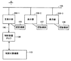
図1を参照して、本発明の実施の形態に係る制御システム10の構成について説明する。図1は、制御システム10の構成の概略を表わす図である。制御システム10は、主表示器200−1と、表示器200−2と、表示器200−3とを備える。主表示器200−1と表示器200−2と表示器200−3とは、通信回線105によって接続されている。通信回線105は、有線または無線のネットワークであり得る。主表示器200−1には、制御装置100と認証機器106とが接続されている。主表示器200−1と制御装置100とはネットワーク190によって接続されている。制御装置100は、たとえばプログラマブルロジックコントローラPLC(Programmable Logic Controller)である。認証機器106は、パスワードの入力を受け付ける公知の認証装置、あるいは生体情報認証装置を含む。生体情報認証装置は、たとえば、指紋認証、声紋認証、虹彩認証、骨相認証などを含み得る。
With reference to FIG. 1, the structure of the
制御装置100には、制御対象機器110が接続されている。制御装置100は、主表示器200−1、表示器200−2,200−3に電気的に接続されている。したがって、主表示器200-1のみならず表示器200−2,200−3も、制御装置100に命令を与えることにより、制御対象機器110の動作を制御することができる。
A
なお、「主表示器」とは、複数の表示器のうちの1つを示す。主表示器は、制御システム10の管理者によって任意に選択可能であり、また、制御システム10が実行する処理の結果に基づいて主表示器が決定されてもよい。したがって、制御システム10において、主表示器は、常に同一の表示器であるとは限らず、動的に変わり得る。
The “main display device” indicates one of a plurality of display devices. The main indicator can be arbitrarily selected by the administrator of the
また、制御装置が接続される表示器は、主表示器200−1に限られず、他の表示器200−2,200−3に接続されてもよい。また、複数の表示器の各々に、制御対象機器が接続された制御装置が接続されてもよい。 The display to which the control device is connected is not limited to the main display 200-1, and may be connected to other displays 200-2 and 200-3. In addition, a control device to which a control target device is connected may be connected to each of the plurality of displays.
表示器200−2には、認証機器107が接続されている。表示器200−3には、認証機器108が接続されている。認証機器107,108は、認証機器106と同様の技術によって実現される。なお、認証機器106,107,108は、本実施の形態に係る制御システム10に必須の構成ではなく、他の局面において、これらの認証機器が含まれない構成が用いられてもよい。
The
主表示器200−1は、制御装置100に対してデータを直接書き込み、あるいはデータを読み出すことができる。主表示器200−1は、表示装置と、タッチパネル式の入力装置とを備える。主表示器200−1は、さらに、制御装置100から送られたデータを表示装置に表示し、また表示装置に対するタッチ操作に基づいて制御装置100に命令を与えることができる。主表示器200−1は、通信回線105によって表示器200−2あるいは表示器200−3との間で通信することができる。たとえば、主表示器200−1は、制御装置100に対する命令の許可を表わす操作権を表示器200−2あるいは表示器200−3に与えることができる。この場合、主表示器200−1は、表示器200−2あるいは表示器200−3から送られるリクエストに基づいて、当該リクエストによって特定されるデータの読み出しあるいは書き込みを制御装置100に対して行なう。主表示器200−1は、表示器200−2あるいは表示器200−3のエージェントとして機能することができる。なお、他の表示器のためのエージェントとして機能する表示器は、主表示器200−1に限られない。他の局面において、表示器200−2,200−3がエージェントとして機能してもよい。
The main display 200-1 can directly write data to or read data from the
さらに、主表示器200−1は、表示器200−2あるいは表示器200−3による制御装置100に対する操作が可能である間、自己に対する命令の入力を受け付けるが、その命令が有効であるか否かの判定を、確定の入力に応答して実行する。確定の入力は、タッチパネル画面に表示されるボタン画像、あるいは、キーボードのエンターキーによって実現される。たとえば、主表示器200−1の画面に画像として表示される確定ボタンがタッチ操作されると、主表示器200−1は、その入力された命令と、直前に有効な命令との間で、優先順位を判断する。この場合、主表示器200−1に対して行なわれるタッチ操作は無効とされるため、表示器200−2あるいは表示器200−3におけるタッチ操作に基づく命令が優先され、主表示器200−1による誤動作が防止される。
Further, the main display 200-1 accepts an input of a command to itself while the display 200-2 or the display 200-3 can operate the
なお、現実には、全く同一のタイミングで確定ボタンがタッチ操作されることは考えにくい。しかしながら、仮に、全く同一のタイミングで確定ボタンがタッチ操作された場合には、いずれの命令も受け付けない、あるいは、予め優先順位の高い表示器を定めておき、その表示器の命令を優先し、他方の命令を受け付けない等の処理を実行してもよい。ここで、「命令を受け付けない」こととは、たとえば、主表示器200−1が、制御装置100に命令に応じた信号を送出しないこと、あるいは、主表示器200−1が、その命令に対する処理を実行しないこと、を意味する。
In reality, it is unlikely that the confirm button is touch-operated at exactly the same timing. However, if the confirm button is touch-operated at exactly the same timing, any command will not be accepted, or a display with a high priority will be determined in advance, and the command of that display will be given priority, Processing such as not accepting the other command may be executed. Here, “not accepting an instruction” means, for example, that the main display 200-1 does not send a signal corresponding to the instruction to the
通信回線105による通信は、たとえばRS(Recommended Standard)232Cその他の通信規格に従って実現される。
Communication via the
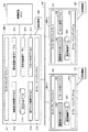
図2を参照して、制御システム10の構成についてさらに詳細に説明する。図2は、主表示器200−1,表示器200−2,200−3によって実現される機能の構成を表わすブロック図である。主表示器200−1は、タッチパネルディスプレイ211と、画面表示制御プロセス212と、画面制御データ213と、操作ロック制御プロセス214と、操作権移行条件テーブル215と、操作権管理テーブル216と、リモート制御プロセス217と、オペレーティングシステム218とを備える。
With reference to FIG. 2, the configuration of the
タッチパネルディスプレイ211は、アナログ式のあるいはデジタル式のタッチパネルと、ディスプレイ装置とによって実現される。タッチパネルディスプレイ211は、主表示器200−1に対するタッチ操作を受け付けて、そのタッチ操作に応じた信号を画面表示制御プロセス212あるいは操作ロック制御プロセス214に送出する。他の局面において、そのタッチ操作は、リモート制御プロセス217にも送出され得る。
The
画面表示制御プロセス212は、主表示器200−1における画面の表示を制御する。画面表示制御プロセス212は、画面制御データ213を用いてそのデータおよび主表示器200−1に与えられる命令またはデータに基づいて画面の表示をタッチパネルディスプレイ211に実現させる。画面表示制御プロセス212は、たとえば、CPU(Central Processing Unit)その他の演算制御装置が、画面の表示を制御するために予め構成されたプログラムを実行することにより実現される。
The screen
画面制御データ213は、タッチパネルディスプレイ211に表示されるべき画面として予め作成された複数の画面と、主表示器200−1に与えられるデータに基づいて表示を切り換えるように構成された部品画像データとを含む。画面制御データ213は、たとえば、ハードディスク装置、フラッシュメモリその他の不揮発性の記憶装置に格納されている。あるいは、他の局面において、画面制御データ213は、主表示器200−1に対して着脱可能な記録媒体に格納されていてもよい。
The
操作ロック制御プロセス214は、主表示器200−1と、表示器200−2または表示器200−3との間で操作権の付与または禁止の制御を実行する。操作ロック制御プロセス214は、CPUその他の演算制御装置が、画面操作のロックを制御するために予め構成されたプログラムを実行することにより実現される。
The operation
操作権移行条件テーブル215は、主表示器200−1に与えられている操作権を他の表示器200−2,200−3との間で移行するための条件を含む。操作権移行条件テーブル215は、操作ロック制御プロセス214において使用され、他の表示器200−2,200−3による操作の要求に基づいて操作権を移行するか否かが判定される。他の局面において、表示器200−2または表示器200−3が操作権を有している場合には、操作権移行条件テーブル215は、その表示器から主表示器200−1に操作権を移行することができるか否かを判定するためにも使用され得る。さらに、たとえば、主表示器200−1は、表示器200−2が有する操作権を表示器200−3に移行することもある。
The operation right transfer condition table 215 includes conditions for transferring the operation right given to the main display 200-1 between the other displays 200-2 and 200-3. The operation right transfer condition table 215 is used in the operation
操作権管理テーブル216は、制御システム10における操作権がどの表示器に保持されているかを管理するためのデータを含む。操作権管理テーブル216は、たとえば各表示器を特定するための識別子と、当該表示器が操作権を有していることを表わすフラグとを含む。なお、本実施の形態における制御システム10は、操作権の単位として、表示器のユーザ、各表示器に表示される画面、画面に含まれる部品画像、部品画像に対するデータの書き込み又は読み出しの命令単位で規定され得る。
The operation right management table 216 includes data for managing which display device holds the operation right in the
リモート制御プロセス217は、通信回線105を介して他の表示器200−2,200−3との間のデータ通信を制御する。リモート制御プロセス217は、ある局面において、表示器200−2または表示器200−3から送られた操作要求を受信し、その要求を操作ロック制御プロセス214に送出する。他の局面において、リモート制御プロセス217は、タッチパネルディスプレイ211に対して与えられるタッチ操作に応答して、他の表示器200−2,200−3に付与された操作権を主表示器200−1が受け取ることができるか否かの問い合せを当該表示器200−2,200−3に送出する。
The
オペレーティングシステム218は、主表示器200−1の基本的な動作を制御する。基本的な動作は、主表示器200−1におけるデータの入出力、データの記憶装置に対する書き込みあるいは記憶装置からのデータの読み出し、その他の演算処理機能を含む。
The
図2を再び参照して、表示器200−2は、タッチパネルディスプレイ221と、画面表示制御プロセス222と、画面制御データ223と、オペレーティングシステム224と、リモート制御プロセス225とを備える。タッチパネルディスプレイ221は、主表示器200−1におけるタッチパネルディスプレイ211と同様に実現される。画面表示制御プロセス222は、画面表示制御プロセス212と同様に実現される。画面制御データ223は、タッチパネルディスプレイ221に表示されるべき画面として予め作成された画面データと当該画面に含まれる部品画像データとを含む。主表示器200−1と表示器200−2とが同じ画面の表示態様を実現する場合には、表示器200−2の画面制御データ223は、主表示器200−1の画面制御データ213と同様のデータとして実現される。オペレーティングシステム224は、オペレーティングシステム218と同様にして実現される。
Referring back to FIG. 2, the display device 200-2 includes a
リモート制御プロセス225は、リモート制御プロセス217と同様に実現される。さらに、画面表示制御プロセス222は、認証機器107から送られる認証のためのデータに基づいて、タッチパネルディスプレイ221における画面の表示を制御する。より詳しくは、認証機器107から送られるデータが表示器200−2に登録されているデータと同じである場合には、画面表示制御プロセス222は、タッチパネルディスプレイ221に対する操作に応答して画面の表示を切り換える。あるいは、認証機器107から送られるデータが表示器200−2に登録されているデータと同じである場合には、リモート制御プロセス225は、通信回線105を介して、主表示器200−1または表示器200−3と通信することができる。なお、画面制御データ223と画面制御データ213とは、必ずしも同じである必要はなく、異なってもよい。
The
表示器200−3は、タッチパネルディスプレイ231と、画面表示制御プロセス232と、画面制御データ233と、オペレーティングシステム234と、リモート制御プロセス235とを備える。表示器200−3の各構成要素は、表示器200−2に含まれる各構成要素と同様にして実現される。したがって、当該構成要素の詳細な説明は繰り返さない。
The display device 200-3 includes a
[ハードウェア構成]
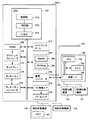
図3を参照して、本実施の形態に係る主表示器200−1の構成についてさらに説明する。図3は、主表示器200−1のハードウェア構成を表わすブロック図である。主表示器200−1は、CPU252と、メンテナンスポート254と、メモリ260と、通信コントローラ266と、VRAM(Video RAM)268と、グラフィックコントローラ270と、ディスプレイ272と、タッチパネル274と、タッチパネルコントローラ276と、I/O(Input/Output)制御I/F(Interface)278と、入出力ユニット(I/Oユニット)279とを備える。主表示器200−1は、制御装置100と、制御対象機器196,198とに電気的に接続されている。制御装置100は、制御対象機器192,194に電気的に接続されている。
[Hardware configuration]
With reference to FIG. 3, the structure of the main display 200-1 which concerns on this Embodiment is further demonstrated. FIG. 3 is a block diagram showing a hardware configuration of main display 200-1. The main display 200-1 includes a
メモリ260は、DRAM(Dynamic RAM)262と、FEPROM(Flash Erasable and Programmable ROM)264とを含む。I/Oユニット279は、制御対象機器196,198その他の機器を接続するための入出力端子、入出力回路などを含む。複数の入出力端子が備えられてもよい。I/O制御I/F278は、CPU252とI/Oユニット279との間で信号の授受を仲介する。I/O制御I/F278は、入出力メモリ、D/A(Digital to Analog)変換器、A/D(Analog to Digital)変換器などを含み得る。
The
CPU252は、制御部310と、判定部320と、付与部330とを含む。制御部310は、制御対象機器110の操作権を有する表示器(以下「操作権保持表示器」ともいう。)として主表示器200−1を選択するための入力に基づいて、制御対象機器110を制御するように構成されている。
The
判定部320は、制御対象機器110についての新たな操作を要求する表示器(以下「操作権要求表示器」ともいう。)と、操作権保持表示器との間で、いずれの表示器に操作権を与えるかを規定する優先順位の高低を判定するように構成されている。たとえば、主表示器200−1が操作権保持表示器であり、表示器200−2が操作権要求表示器である場合、判定部320は、表示器200−2と主表示器200−1との間で、各々が有する優先順位の高低を判定する。
The
付与部330は、当該優先順位が高いと判定された表示器に、操作権を与えるように構成されている。上記の例で、たとえば、表示器200−2の優先順位が、主表示器200−1の優先順位を上回る場合、主表示器200−1のCPU252は、付与部330として、当該操作権を表わす信号を、通信回線105を介して、表示器200−2に送出する。表示器200−2は、操作権が付与されると、制御対象機器110に対して命令を送出することができる。これにより、制御システム10の管理者は、表示器200−2を用いて制御対象機器を操作することができる。
The assigning
上記の例で、操作権の移行の要否は、たとえば、タッチパネル274に表示される実行キーの押下に応答して、判定される。主表示器200−1が、通常の構成を有するパーソナルコンピュータによって実行される場合には、当該要否の判定は、そのパーソナルコンピュータに接続されたキーボード(図示しない)のリターンキーの押下に応答して、実行される。
In the above example, whether or not the operation right needs to be transferred is determined in response to pressing of the execution key displayed on the
CPU252は、FEPROM264に格納されたプログラムに基づいて、画面表示制御プロセス212、操作ロック制御プロセス214、リモート制御プロセス217とをそれぞれ実現する。たとえば、CPU252は、画面表示制御プロセス212として、VRAM268にデータを書き込み、グラフィックコントローラ270を用いてディスプレイ272に画面を表示させる。あるいは、CPU252は、I/O制御I/F278または通信コントローラ266を介して与えられた他の表示器200−2,200−3からの要求に基づいて、これらの要求を受け付けるか否かを判定する。あるいは、他の局面において、CPU252は、操作ロック制御プロセス214として、タッチパネル274に対する操作を受け付けるか否かを判定する。さらに、CPU252は、リモート制御プロセス217として、通信コントローラ266を介して制御装置100を制御する。あるいは、CPU252は、制御装置100によって出力されたデータを受信する。
The
メンテナンスポート254は、主表示器200−1の保守時などにおいて一時的に使用される。表示器200−1に表示される画面を変更する場合、あるいはディスプレイ272に表示される画面の設定を変更する場合などには、新しい画面データがメンテナンスポート254を介して入力される。これにより、主表示器200−1と制御装置100との通信が妨げられることなく、主表示器200−1の画面のデータを更新することができる。
The
DRAM262は、主に、ディスプレイ272における表示制御その他の処理に用いられるデータを一時的に保持する。CPU252は、FEPROM264に格納されている色相データをDRAM262に読み出す。
The
ある局面において、色相データは、画像を構成する第1の色相データと変更後の第2の色相データとを含む。CPU252は、制御対象機器196,198の各状態を表わす実データ(状態表示値)と、各状態に応じて予め設定された基準値とを比較して、その比較の結果に応じて画像の色相を変更する。
In one aspect, the hue data includes first hue data constituting the image and changed second hue data. The
より詳しくは、状態標準値と基準値とが一致する場合に、CPU252は当該値を表わす色相に変更するように、基準値を設定してもよい。あるいは、状態表示値が基準値を上回る場合に、CPU252は色相を変更するように基準値を設定してもよい。さらに、状態表示値が基準値を下回る場合に、CPU252は色相を変更するように基準値を設定してもよい。
More specifically, when the state standard value matches the reference value, the
FEP264は、データの書き替えが可能なフラッシュメモリとして実現される。このようなフラッシュメモリは、可動部を持たず、また衝撃に強いため、制御装置100に接続される環境が劣悪であっても、主表示器200−1は、安定して作動することができる。
The
FEPROM264は、ディスプレイ272に表示される画像の色を規定する色コード(色相データ)を格納している。CPU252は、当該コードを用いてディスプレイ272に表示するための画像データを、VRAM268に書き込む。より詳しくは、CPU252は、制御対象機器292,294,296,298の各々の状態を表わすデータに応じて色コードを選択し、選択後の色コードを用いた画像データを生成し得る。
The
通信コントローラ266は、通信回線105およびネットワーク190に接続されている。通信コントローラ266は、CPU252の制御に基づいて、主表示器200−1と制御装置100との間でデータ通信を行なう。通信されるデータには、制御装置から送られるデータであって、実績その他の稼動状況を表わすデータ、あるいは、主表示器200−1から制御装置100に送信される設定データなどを含み得る。
The
VRAM268は、CPU252の制御に基づいて、画面表示用のデータを一時的に保持する。このデータは、グラフィックコントローラ270によって読み出され、ディスプレイ272に送出される。これにより、ディスプレイ272は、当該データに応じた画面を表示することができる。
The
タッチパネルコントローラ276は、タッチパネル274とデータバスとの間に配置され、タッチパネル274に対するタッチ操作を検出する。タッチパネルコントローラ276がそのタッチ操作を検出すると、その位置あるいは入力されたデータは、メモリ260に送られる。
The
上記の構成のように、主表示器200−1は、I/O制御I/F278およびI/Oユニット279を備えているため、制御装置100を介することなく、制御対象機器に直接接続することができる。したがって、主表示器200−1は、制御対象機器196,198の状態の表示あるいは動作の制御の指示を直接実行することができる。
Since the main display 200-1 includes the I / O control I /
なお、主表示器200−1の構成は、上述のものに限られない。たとえば、主表示器200−1は、グラフィック表示を行なうため、操作盤、スイッチ、表示灯などの機能を有する他、デバイスその他の制御対象機器の稼動状況や作業指示のような管理のための各種のモニタ、各制御対象機器に対する設定値の入力を受け付ける端末としての機能を備えていればよい。 In addition, the structure of the main display 200-1 is not restricted to the above-mentioned thing. For example, the main display 200-1 has functions such as an operation panel, a switch, and an indicator lamp for performing graphic display, as well as various types of management such as operation status and work instructions of devices and other control target devices. And a function as a terminal that accepts input of set values for each control target device.
このような主表示器200−1で表示される画面は、画面作成プログラムによってユーザが作成することができる。たとえば、画面作成プログラムがPC(Personal Computer)にインストールされると、そのPCは画面エディタ装置として機能する。画面エディタ装置が起動すると、編集のための画面が表示される。ユーザは、その画面において、各制御対象機器のそれぞれの状態を表示するための表示画面、あるいは、各制御対象機器を制御する命令の入力を受け付ける制御画面などを構成する画像ブロックを使用し、操作の可否を設定することができる。なお、以下の説明において、当該表示画面、制御画面等を監視画面と総称する。ここで、画像ブロックとは、たとえば、監視画面そのもの、監視画面に表示されるランプ、スイッチ、カウンタ、メータ表示器、グラフ表示器などの部品画像(シンボル)、あるいは、監視画面や部品画像に付加的に表示される補助画像(たとえば、ポップアップウインドウ画面)などの画像を言うが、これらに限られない。また、部品画像、補助画像などは、ユーザがすべてデザインしてもよく、あるいは予めテンプレートとして定められた画像であってもよい。 The screen displayed on the main display 200-1 can be created by the user using a screen creation program. For example, when a screen creation program is installed in a PC (Personal Computer), the PC functions as a screen editor device. When the screen editor device is activated, a screen for editing is displayed. On the screen, the user uses an image block that constitutes a display screen for displaying the status of each control target device or a control screen for receiving an input of a command for controlling each control target device. Can be set. In the following description, the display screen, the control screen, and the like are collectively referred to as a monitoring screen. Here, the image block is, for example, a monitor screen itself, a component image (symbol) such as a lamp, switch, counter, meter display, or graph display displayed on the monitor screen, or added to the monitor screen or component image. An image such as an auxiliary image (for example, a pop-up window screen) that is displayed automatically is referred to, but is not limited thereto. Further, the component image, the auxiliary image, and the like may all be designed by the user, or may be an image determined in advance as a template.
図3を再び参照して、制御装置100は、ネットワーク190を介して主表示器200−1と接続される。制御装置100はさらに、制御対象機器192,194に接続される。制御装置100は、予め設定された制御プログラムを実行することにより、制御対象機器192,194の動作を制御する。制御対象機器192,194は、たとえば、自動組立機、ベルトコンベアなどがあるが、これらの機器に限られない。また、制御装置100に接続される制御対象機器の画像は特定の画像に限られない。
Referring to FIG. 3 again, the
主表示器200−1が表示可能な画面のデータは、当該画面を編集するための画面エディタ装置から主表示器200−1に送られる。なお、画面データの授受は、通信回線105によって行なわれる場合に限られず、たとえばフラッシュメモリその他の着脱可能なデータ記録媒体を介して行なわれてもよい。
The screen data that can be displayed on the main display 200-1 is sent to the main display 200-1 from a screen editor device for editing the screen. Note that the transfer of screen data is not limited to being performed via the
また、本実施の形態においては、当該画面エディタ装置と表示器200−1とが別途の構成として示されている。しかしながら、主表示器200−1が画面エディタ装置としても機能する構成が用いられてもよい。 In the present embodiment, the screen editor device and the display 200-1 are shown as separate components. However, a configuration in which the main display 200-1 also functions as a screen editor device may be used.
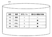
[データ構造]
図4を参照して、本実施の形態に係る制御システム10のデータ構造について説明する。図4は、操作権移行条件テーブル215の構成を概念的に表わす図である。操作権移行条件テーブル215は、番号410と、第1の条件420と、第2の条件430と、第3の条件440と、第4の条件450と、操作権の移行を行なうか否かを表わすデータ460とを含む。
[data structure]
With reference to FIG. 4, the data structure of
番号410は、操作権の移行を行なうか否かの判定条件のパターンを表わす。第1の条件420は、操作権の移行のための判定基準が、当該表示器にログインしているユーザ単位で行なわれることを表わす。第2の条件430は、操作権の移行の有無の判定が、現在作動している表示器と新たに操作権を得ようとする表示器とが表示している画面のレベルに基づいて行なわれることを表わす。第3の条件440は、操作権の移行の判定が表示されている画面に含まれる部品の許可レベルに従って行なわれることを表わす。第4の条件450は、操作権の移行の判定が当該部品について書込機能を有する部品の操作権の有無に基づいて行なわれることを表わす。判定結果460は、操作権の移行を行なうか否かについて規定された条件を表わす。 Reference numeral 410 represents a pattern of determination conditions for determining whether or not to transfer the operation right. The first condition 420 represents that the determination criterion for the transfer of the operation right is performed for each user who logs in to the display device. In the second condition 430, whether or not the operation right has been transferred is determined based on the level of the screen displayed by the display device that is currently operating and the display device that is newly acquiring the operation right. Represents. The third condition 440 represents that the operation right transfer determination is performed according to the permission level of the component included in the displayed screen. The fourth condition 450 represents that the determination of the transfer of the operation right is performed based on the presence / absence of the operation right of the part having the writing function for the part. The determination result 460 represents a condition defined as to whether or not to transfer the operation right.
(1) 第1の条件420
表示器のユーザが有する許可レベルが、表示器間における操作権の授受の判断に使用される。具体的には、主表示器200−1、表示器200−2,200−3等の各表示器は、不特定多数のユーザが操作することを防止するために、認証機能を有する。たとえば、図1に示されるように、各表示器には、認証機器が接続されている。この場合、操作の割り込みを要求する表示器(以下「表示器A」ともいう。)にログインしているユーザの許可レベルが、操作のロック元になっている表示器(以下「表示器B」ともいう。)にログインしているユーザが有する許可レベルよりも高い場合には、表示器Aに操作権が与えられ、表示器Aのユーザによる操作が受け付けられる。
(1) First condition 420
The permission level possessed by the user of the display device is used to determine whether or not to give the operation right between the display devices. Specifically, each display device such as the main display device 200-1, the display devices 200-2 and 200-3 has an authentication function in order to prevent an unspecified number of users from operating. For example, as shown in FIG. 1, an authentication device is connected to each display. In this case, the permission level of the user who has logged in to the display device that requests an operation interruption (hereinafter also referred to as “display device A”) is the display device (hereinafter “display device B”) that is the operation lock source. If it is higher than the permission level possessed by the logged-in user, the operation right is given to the display A, and the operation by the user of the display A is accepted.
(2) 第2の条件430
表示器に表示されている画面ごとの許可レベルが、操作権の授受の判断に使用される。具体的には、表示器に表示される各画面には、許可レベルが設定されている。この場合、当該表示器に表示されている画面の許可レベルが、表示対象として選択された他の画面の許可レベルを上回らなければ、当該ユーザによる画面の切り換え操作は有効であると判定されず、画面の表示は切り換えられない。たとえば、一般のユーザが有する許可レベルよりも高い許可レベルを有する管理者は、一般のユーザが使用する画面を操作する場合がある。この場合、ユーザの許可レベルの判断(第1の条件420)に加えて、各表示器において表示されている画面の許可レベルの比較結果に応じて操作権の移行の要否が判断される。これにより、画面ごとの重要度が操作権の移行の要否に反映されるため、画面の表示制御をより的確に実現することが可能となる。
(2) Second condition 430
The permission level for each screen displayed on the display is used to determine whether or not to give the operation right. Specifically, a permission level is set for each screen displayed on the display. In this case, if the permission level of the screen displayed on the display device does not exceed the permission level of the other screen selected as the display target, the screen switching operation by the user is not determined to be effective, The screen display cannot be switched. For example, an administrator who has a higher permission level than a general user may operate a screen used by the general user. In this case, in addition to the determination of the permission level of the user (first condition 420), whether or not it is necessary to transfer the operation right is determined according to the comparison result of the permission level of the screen displayed on each display. Thereby, since the importance for each screen is reflected in whether or not the operation right needs to be transferred, it is possible to more accurately realize the display control of the screen.
(3) 第3の条件440
画面に表示される部品画像(ランプ画像、スイッチ画像)に設定される許可レベルが、操作権の授受の判断に使用される。したがって、操作権の授受の判断は、操作しようとしている部品画像レベルで行なうことができる。たとえば、ランプ画像に関連付けられている許可レベルと、スイッチ画像に関連付けられている許可レベルとの大小が判定される。これにより、設定内容を表示するための部品画像と、設定内容の変更を受け付けるための部品画像との間で、操作権の授受を制限することが可能となる。画面単位の許可レベルの判断よりも、よりきめ細かな表示制御が可能となる。
(3) Third condition 440
The permission level set for the component image (lamp image, switch image) displayed on the screen is used to determine whether to give the operation right. Therefore, it is possible to determine whether to give or receive the operation right at the part image level to be operated. For example, it is determined whether the permission level associated with the lamp image and the permission level associated with the switch image are large or small. Thereby, it is possible to restrict the transfer of the operation right between the component image for displaying the setting content and the component image for receiving the change of the setting content. Finer display control than the determination of the permission level for each screen is possible.
(4) 第4の条件450
画面に表示される部品画像を用いたデータの書き込み機能の有無に応じて、操作権の授受が判断される。たとえば、データの書き込みが行なわれないような部品画像(たとえば、設定値を表示するための操作を受け付けるアイコン)、あるいは、データの書き込みが禁止されているように構成された部品画像(画面データの作成時にそのような設定が反映されている画像)に対する操作が行なわれた場合、あるいは、アクセスが、その部品画像に設定された許可レベルを下回る許可レベルを有するユーザから行なわれた場合には、その表示器から制御装置100への命令の送信が行なわれ得ない。したがって、これらの操作は、制御装置100の誤動作の原因とはなりえない。そこで、このような部品画像に対する操作が行なわれた場合には、主表示器200−1は、当該操作のロックを行なわない。
(4) Fourth condition 450
Whether or not to give an operation right is determined according to the presence or absence of a data writing function using a component image displayed on the screen. For example, a component image in which data writing is not performed (for example, an icon for accepting an operation for displaying a set value), or a component image configured to prohibit data writing (screen data When an operation is performed on an image in which such settings are reflected at the time of creation, or when access is performed by a user having a permission level lower than the permission level set for the component image, The command cannot be transmitted from the display unit to the
図4を再び参照して、たとえば、判定パターン「1」では、第1の条件420と第2の条件430と第3の条件440とはすべて適用されないことが規定されている。この場合、第4の条件450および判定結果460が参照される。ここで、第4の条件450によると、書込機能を有する部品の操作権の有無が規定されている。判定パターン「1」の場合には、当該操作権は「なし」との判定条件が規定されている。また、判定結果460によると、操作権の移行を行なわない旨規定されている。したがって、判定パターン「1」については、判定の結果、操作権が移行されないことになる。 Referring to FIG. 4 again, for example, in the determination pattern “1”, it is defined that the first condition 420, the second condition 430, and the third condition 440 are not all applied. In this case, the fourth condition 450 and the determination result 460 are referred to. Here, according to the fourth condition 450, presence / absence of an operation right of a component having a writing function is defined. In the case of the determination pattern “1”, the determination condition that the operation right is “none” is defined. Further, the determination result 460 stipulates that the operation right is not transferred. Therefore, for the determination pattern “1”, the operation right is not transferred as a result of the determination.
なお、判定パターンの種類は、図4に示されるものに限られず、各条件を変更することにより組み合せ可能となる他の判定パターンがさらに用いられてもよい。 Note that the types of determination patterns are not limited to those shown in FIG. 4, and other determination patterns that can be combined by changing each condition may be further used.
図5を参照して、他の局面における操作権移行条件テーブル215について説明する。図5は、ユーザの許可レベルの値が「10」よりも大きい許可レベルを有するユーザに適用されることを表わす操作権移行条件テーブル215を表示する。以下の例では、数値が大きいほど許可レベルが高いものとして説明するが、数値の大小関係と許可レベルの高低との関係は、逆であってもよい。 With reference to FIG. 5, the operation right transfer condition table 215 in another aspect will be described. FIG. 5 displays an operation right transfer condition table 215 indicating that the user permission level value is applied to a user having a permission level greater than “10”. In the following example, it is assumed that the larger the numerical value is, the higher the permission level is. However, the relationship between the numerical value relationship and the permission level level may be reversed.
詳しくは、他の局面に従う操作権移行条件テーブル215は、番号510と、第1の条件520と、第2の条件530と、第3の条件540と、第4の条件550と、第5の条件560とを含む。第1の条件520から第4の条件550までは、図4に示される第1の条件420から第4の条件450と同じである。したがってそれらの説明は繰り返さない。第5の条件560は、割込処理を行なうか否かの設定を含む。たとえば、判定パターン「1」の場合、割込処理を「行なわない」と規定されている。一方、判定パターン「3」によると、割込処理を「行なう」と規定されている。
Specifically, the operation right transfer condition table 215 according to another aspect includes the
また、第1の条件520に関し、判定パターン「3」によると、新たな操作権を得ようとする表示器のユーザAの許可レベルが現在の操作権を有する表示器のユーザBの許可レベルを上回り、かつ、ユーザAの許可レベルが「10」よりも大きいことが求められている。このようにすると、表示器のユーザに対する許可レベルによる制限に加えて、その許可レベルの絶対値に応じた制御を実現することができる。
Further, regarding the
[制御構造]
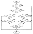
図6を参照して、本実施の形態に係る主表示器200−1の制御構造について説明する。図6は、操作ロック制御プロセス214を実行するCPU252が実現する一連の動作の一部を表わすフローチャートである。
[Control structure]
With reference to FIG. 6, the control structure of main display 200-1 according to the present embodiment will be described. FIG. 6 is a flowchart showing a part of a series of operations realized by
ステップS610にて、CPU252は、第1の条件が成立しているか否かを判定する。たとえば、CPU252は、操作権を新たに得ようとする表示器のユーザの許可レベルが現在の操作権を有する表示器のユーザBの許可レベルを上回っていると判定すると、制御をステップS620に切り換える。そうでない場合には、CPU252は処理を終了する。
In step S610,
ステップS620にて、CPU252は、第2の条件530が成立しているか否かを判定する。第2の条件が成立している場合には(ユーザAの許可レベル>ユーザBの許可レベル)、CPU252は、制御をステップS630に切り換える。そうでない場合には(ユーザAの許可レベル≦ユーザBの許可レベル)、CPU252は、制御をステップS650に切り換える。
In step S620,
ステップS630にて、CPU252は、第3の条件540が成立しているか否かを判定する。CPU252は、第3の条件が成立していると判定すると(ユーザAの許可レベル=ユーザBの許可レベル)、制御をステップS640に切り換える。そうでない場合には、CPU252は、処理を終了する。
In step S630,
ステップS640にて、CPU252は、第4の条件550が成立しているか否かを判定する。CPU252は、第4の条件が成立していると判定すると(書込機能を有する部品の操作権は「ある」)、制御をステップS670に切り換える。そうでない場合には(書込機能を有する部品の操作権は「ない」)、CPU252は、処理を終了する。
In step S640,
ステップS650にて、CPU252は、第3の条件540が成立しているか否かを判定する。CPU252は、第3の条件が成立していると判定すると(ユーザAの許可レベル>ユーザBの許可レベル)、制御をステップS660に切り換える。そうでない場合には(ユーザAの許可レベル≦ユーザBの許可レベル)、CPU252は処理を終了する。
In step S650,
ステップS660にて、CPU252は、第4の条件550が成立しているか否かを判定する。CPU252は、第4の条件が成立していると判定すると(書込機能を有する部品の操作権は「ある」)、制御をステップS670に切り換える。そうでない場合には(書込機能を有する部品の操作権は「ない」)、CPU252は、処理を終了する。
In step S660,
ステップS670にて、CPU252は、操作権移行処理を実行する。この処理が実行されると、主表示器200−1と他の表示器(たとえば表示器200−2または表示器200−3)との間で操作権の移行が実現される。たとえば、CPU252は、操作の要求を送信した表示器200−2に対して、当該要求に基づいて操作権を主表示器200−1から表示器200−2に送ることを示すデータを生成し、そのデータを当該要求に対する回答として表示器200−2に送信する。この操作権を受け取った表示器200−2は、その後タッチパネルディスプレイ221に対するタッチ操作に基づいて制御対象機器110の操作を実行することができる。この場合、表示器200−2は、主表示器200−1に対してタッチパネルディスプレイ221に対する操作を表わすデータと当該データの処理の要求を送信する。主表示器200−1は、これらのデータを受信すると、そのデータに基づいて制御装置100との間でデータの書き込みあるいは読み出しを実行する。
In step S670,
図7および図8を参照して、本実施の形態に係る主表示器200−1の画面の表示態様について説明する。図7は、主表示器200−1のタッチパネルディスプレイ211に表示される画面の一例を表わす図である。
With reference to FIG. 7 and FIG. 8, the display mode of the screen of the main display 200-1 which concerns on this Embodiment is demonstrated. FIG. 7 is a diagram illustrating an example of a screen displayed on
タッチパネルディスプレイ211は、主表示器200−1に保存されている画面制御データ213に基づいて、温度確認画面710を表示する。温度確認画面710は、「場所変更」の入力を受け付けるボタン画像720と、「単位変更」の入力を受け付けるボタン画像730と、画面を切り換えるための操作を受け付けるボタン画像740とを含む。
The
図8は、画面制御データ213の一例を表わす図である。画面制御データ213は、温度確認画面710を表示するためのデータと、ボタン画像720,730,740をそれぞれ表示するための各データとを含む。
FIG. 8 is a diagram illustrating an example of the
各データには、種類、許可レベル、書き込み機能の有無が関連付けられている。たとえば、温度確認画面710を表示するためのデータは、画像の種類が「画面」であること、アクセスの許可レベルは「1」であること、書き込み機能は規定されていない、ということを規定している。したがって、使用者の許可レベルが「1」以上であれば、アクセスは許可される。許可レベルを有さない使用者、たとえば、許可レベルが「0」である使用者によるアクセスは禁止される。なお、本実施の形態における「使用者」とは、表示器のオペレータ、管理者その他の人間に加えて、表示器自体を含むものとする。
Each data is associated with the type, permission level, and presence / absence of a write function. For example, the data for displaying the
また、ボタン画像730を表示するためのデータは、画像の種類が「ボタン」であること、アクセスの許可レベルは「2」であること、書き込み機能は「無い」ことを、規定している。したがって、アクセスを要求している使用者の許可レベルが、「2」以上である場合には、当該画像に対するアクセスが許可されるが、許可レベル「1」を有する使用者には許可されない。
The data for displaying the
図9は、主表示器200−1のタッチパネルディスプレイ211に表示される他の画面の一例を表わす図である。タッチパネルディスプレイ211は、画面制御データ213に基づいて、温度設定画面910を表示する。温度設定画面910は、数値入力器画像920,930,940と、ボタン画像950,970,980と、数値の入力を受け付けるキーパッド画像960とを含む。
FIG. 9 is a diagram illustrating an example of another screen displayed on
数値入力器画像920は、炉心の設定温度の入力を受け付ける。具体的には、キーパッド画像960に対する操作によって入力される数値を受け付けて、炉心の設定温度を保持するために確保されたメモリ領域に当該数値を書き込む。設定温度が入力されると、その後、当該制御対象機器は、その温度を制御目標値として制御される。
The numerical value
数値入力画像930は、内壁の設定温度の入力を受け付ける。具体的には、キーパッド画像960に対する操作によって入力される数値を受け付けて、内壁の設定温度を保持するために確保されたメモリ領域に当該数値を書き込む。その後、当該制御対象機器は、その温度を制御目標値として制御される。
The
数値入力画像940は、冷却水の設定温度の入力を受け付ける。具体的には、キーパッド画像960に対する操作によって入力される数値を受け付けて、冷却水の設定温度を保持するために確保されたメモリ領域に当該数値を書き込む。その後、当該制御対象機器は、その温度を制御目標値として制御される。
The numerical
ボタン画像950は、上記の各温度の単位を変更するための操作を受け付ける。ボタン画像950に対する操作が行なわれると、タッチパネルディスプレイ211は、温度設定画面910に代えて、温度単位変更画面を表示する。
The
ボタン画像970は、温度確認画面710(図7)を表示する操作を受け付ける。ボタン画像970に対する操作が行なわれると、タッチパネルディスプレイ211は、温度設定画面910に代えて、温度確認画面710を表示する。
The
ボタン画像980は、緊急作業画面を表示する操作を受け付ける。ボタン画像980に対する操作が行なわれると、タッチパネルディスプレイ211は、温度設定画面910に代えて、緊急作業画面を表示する。
The
図10は、図9に規定される画面および画像を表示する画面制御データ213の一例を表わす図である。画面制御データ213は、温度設定確認画面910を表示するためのデータと、数値入力器画像920,930,940を表示するための各データと、ボタン画像950,970,980を表示するための各データと、キーパッド画像960を表示するためのデータとを含む。
FIG. 10 is a diagram illustrating an example of
各データには、図8の場合と同様に、各データごとに(領域1010)、種類(領域1020)、許可レベル(領域1030)、書き込み機能の有無(領域1040)が関連付けられている。たとえば、温度確認画面910を表示するためのデータは、画像の種類が「画面」であること、アクセスの許可レベルは「2」であること、書き込み機能は規定されていない、ということを規定している。したがって、たとえば、アクセスの許可レベル「1」を有する使用者によるアクセスが要求されても、当該アクセスは許可されない。
As in the case of FIG. 8, each data is associated with each data (area 1010), type (area 1020), permission level (area 1030), and presence / absence of a write function (area 1040). For example, the data for displaying the
また、数値入力器画像920を表示するためのデータは、画像の種類が「数値入力器」であること、アクセスの許可レベルは「3」であること、書き込み機能は「有る」ことを規定している。したがって、アクセスを要求している使用者の許可レベルが、「3」以上である場合には、当該画像に対するアクセスが許可され、キーパッド画像960を用いた入力によるデータの書き込みが可能となる。一方、その使用者の許可レベルが「2」以下であれば、アクセスが禁止されるため、データの書き込みも行なわれない。
The data for displaying the numerical
[データ構造]
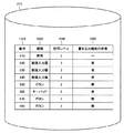
図11を参照して、本実施の形態に係る制御システム10のデータ構造の他の一例について説明する。図11は、操作権移行条件テーブル215の他の構成を概念的に表わす図である。操作権移行条件テーブル215は、番号1710と、第1の条件1720と、第2の条件1730と、第3の条件1740と、第4の条件1750と、操作権の移行を行なうか否かを表わす制御データ1760とを含む。
[data structure]
With reference to FIG. 11, another example of the data structure of
番号1710は、操作権の移行を行なうか否かの判定条件のパターンを表わす。第1の条件1720は、操作権の移行のための判定基準が、当該表示器にログインしているユーザ単位で行なわれることを表わす。第2の条件1730は、操作権の移行の有無の判定が、現在作動している表示器と新たに操作権を得ようとする表示器とが表示している画面の許可レベルに基づいて行なわれることを表わす。第3の条件1740は、操作権の移行の判定が、表示されている画面に含まれる部品の許可レベルに従って行なわれることを表わす。第4の条件1750は、操作権の移行の判定が、当該部品について書込機能を有する部品の操作権の有無に基づいて行なわれることを表わす。制御データ1760は、操作権の移行を行なうか否かについて規定された条件を表わす。
たとえば、判定パターン「2」では、条件1720,1740に示されるように、操作権を新たに得ようとする表示器Aのユーザ単位の許可レベルおよび操作しようとする部品単位の許可レベルは、いずれも、操作権を現在有する表示器Bのユーザ単位の許可レベルおよび操作しようとする部品単位の許可レベルよりも大きい。したがって、表示器Aによる要求に応じて、操作権が表示器Bから表示器Aに移行され得る。
For example, in the determination pattern “2”, as indicated by the
たとえば、表示器Bとしての主表示器200−1が、図10のデータに基づいて、画像930の画面を表示しているときに、表示器Aとしての表示器200−2が、画像920の表示を要求した場合を説明する。この場合、図10に示されるデータから、画像930の許可レベルは「2」として規定されており、画像920の許可レベルは「3」として規定されている。したがって、表示器200−2からのアクセス要求は受け入れられて、操作権が主表示器200−1から表示器200−2に移行される。その結果、表示器200−2は、画像920へのタッチ操作に基づいて「炉心」の温度の設定のための入力を受け付ける。
For example, when the main display 200-1 as the display B is displaying the screen of the
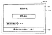
図12および図13を参照して、表示器200−3における画面の表示態様について説明する。図12は、タッチパネルディスプレイ231が表示する画面の一例を表わす図である。図13は、表示器200−3における操作のロックが解消した場合に表示される画面1210を表わす図である。
With reference to FIG. 12 and FIG. 13, the display mode of the screen in the display device 200-3 will be described. FIG. 12 is a diagram illustrating an example of a screen displayed on
図12に示すように、タッチパネルディスプレイ231は、画面1110を表示する。画面1110は、緊急作業または緊急停止のための操作と、温度設定画面への切り換え操作とを受け付ける。
As illustrated in FIG. 12, the
しかしながら、画面1110は、さらに、メッセージ画像1120を表示している。メッセージ画像1120は、タッチパネルディスプレイ231に対する操作がロックされていることを表示している。すなわち、表示器200−3に対する操作は、主表示器200−1によって一時的に禁止されている。この禁止は、たとえば、主表示器200−1における排他制御によって実行される。これにより、タッチパネルディスプレイ231に対する操作が行なわれても、その操作に応じた信号が主表示器200−1において拒絶され、当該操作に起因するデータの書き込み、読み出し等が行なわれない。信号が拒絶されるとは、たとえば当該信号が主表示器200−1よりも先の制御装置100に送られないことを意味する。たとえば、ボタン画像1130に対するタッチ操作が行なわれても、「温度設定画面」は表示されない。これにより、表示器200−3に対する操作に基づく誤動作が防止される。
However, the
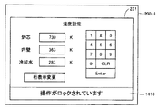
図13を参照して、たとえば、表示器200−3に接続されている認証機器108に対する操作によって、表示器200−3の使用者の許可レベルが、主表示器200−1の使用者の許可レベルを上回ることが、主表示器200−1によって確認された場合、主表示器200−1は、操作のロックを解消する。そして、主表示器200−1は、表示器200−3によって表示されている緊急作業画面1210に対する操作を許可する操作権を、表示器200−3に与える。これにより、表示器200−3は、タッチパネルディスプレイ231に対する操作を受け付けることができる。
Referring to FIG. 13, for example, by the operation on
たとえば、使用者が、ボタン画像1220を押下すると、表示器200−3は、その押下に応答して「緊急停止」のリクエストを、主表示器200−1に送る。主表示器200−1は、そのリクエストによって特定される制御装置100の作動を緊急停止する。あるいは、他の例として、使用者がボタン画像1230を押下すると、タッチパネルディスプレイ231は、温度設定画面を表示する。このとき表示される温度設定画面は、たとえば、主表示器200−1によって表示される温度設定画面910(図9)である。これにより、表示器200−3の使用者は、制御装置100に対する温度を、主表示器200−1を用いずに設定することができる。
For example, when the user presses the
[データ構造]
図14を参照して、表示器200−3のデータ構造について説明する。図14は、図13に規定される画面および画像を表示する画面制御データ233の一例を表わす図である。画面制御データ233は、緊急作業画面1210を表示するためのデータと、ボタン画像1220,1230を表示するための各データとを含む。
[data structure]
The data structure of the display 200-3 will be described with reference to FIG. FIG. 14 is a diagram illustrating an example of
各データには、図8の場合と同様に、各データについて(領域1310)、種類(領域1320)、許可レベル(領域1330)、書き込み機能の有無(領域1340)が関連付けられている。たとえば、緊急作業画面1210を表示するためのデータは、画像の種類が「画面」であること、アクセスの許可レベルは「3」であること、書き込み機能は規定されていない、ということを規定している。したがって、たとえば、アクセスの許可レベル「2」を有する使用者によるアクセスが要求されても、当該アクセスは許可されない。一方、使用者の許可レベルが「3」以上である場合には、認証機器108による認証処理の結果に基づいて、画面のアクセスが許可される。
Similarly to the case of FIG. 8, each data is associated with each data (area 1310), type (area 1320), permission level (area 1330), and presence / absence of a write function (area 1340). For example, the data for displaying the
[操作権の移行前後の画面]
図15および図16を参照して、表示器200−3における操作権の移行について説明する。図15は、表示器200−3に対する操作がロックされている場合に表示される画面を表わす図である。図16は、表示器200−3におけるロックが解除された場合に表示される画面を表わす図である。
[Screen before and after transfer of operation rights]
With reference to FIG. 15 and FIG. 16, the transfer of the operation right in the display device 200-3 will be described. FIG. 15 is a diagram illustrating a screen displayed when an operation on display device 200-3 is locked. FIG. 16 is a diagram showing a screen displayed when the lock on display 200-3 is released.
図15に示すように、表示器200−3のタッチパネルディスプレイ231は、メッセージ画像1410を表示する。メッセージ画像1410は、タッチパネルディスプレイ231に対する操作がロックされていることを表示している。このとき、タッチパネルディスプレイ231に対するタッチ操作が行なわれても、表示器200−3は、そのタッチ操作を有効な操作として受け付けないため、誤操作が防止される。なお、タッチ操作が有効であるか否かの判定は、たとえば、リターンキーその他の確定ボタンを押下した際に優先順位に基づいて行なわれる。直前に有効であった命令よりも優先順位が低いと判定された表示器からの命令は、拒絶される。
As illustrated in FIG. 15, the
しかしながら、緊急の事態などによって表示器200−3に対する操作が必要になる場合がある。この場合、使用者は、表示器200−3に接続される認証機器108に対する入力に基づいて、表示器200−3を操作する権利(操作権)を得ることができる。すなわち、認証機器108に入力された情報(使用者コード等)によって特定されるアクセスの許可レベルが主表示器200−1によって規定されている許可レベル以上である場合には、表示器200−3から制御装置100へのアクセスが主表示器200−1によって許可される。主表示器200−1は、表示器200-3に対して、アクセスが許可されて操作権が表示器200−3に与えられることを示す信号を送出する。表示器200−3は、その信号を受信すると、タッチパネルディスプレイ231に対する操作を受け付けて、主表示器200−1に対して、制御装置100へのアクセスを要求する。
However, an operation on the display 200-3 may be necessary due to an emergency situation or the like. In this case, the user can obtain a right (operation right) to operate the display device 200-3 based on an input to the
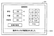
具体的には、図16を参照して、表示器200−3は、主表示器200−1から上記信号を受信すると、メッセージ画像1510をタッチパネルディスプレイの下部の領域に表示する。メッセージ画像1510は、操作権が主表示器200−1から表示器200−3に移行されたことを表わす。これにより、表示器200−3の使用者は、表示器200−3における操作が許可されたことを認識することができる。
Specifically, referring to FIG. 16, when receiving the signal from main display 200-1, display 200-3
図17は、操作権を与えた主表示器200−1における画面の表示態様を表わす図である。この画面は、図7に示される画面に対応する。より詳しくは、主表示器200−1は、表示器200−3に対して操作権を与えたたため、メッセージ画像1610を表示して、主表示器200−1に対するタッチ操作が受け付けられない旨を通知する。これにより、主表示器200−1の使用者は、主表示器200−1に対する操作ができないことを認識することができる。
FIG. 17 is a diagram illustrating a screen display mode on main display 200-1 to which an operation right is given. This screen corresponds to the screen shown in FIG. More specifically, since the main display 200-1 has given the operation right to the display 200-3, the main display 200-1 displays a
[実施例の効果]
以上のようにして、本発明の実施の形態に係る制御システム10は、ユーザ、画面、部品画像の各許可レベル、または、部品画像に対するデータの書き込み機能の有無に基づいて、許可レベルの比較によって導かれる優先度の高低に応じて、操作権の授受の可否を判断する。これにより、簡便に制御システムにおける誤動作を防止することができる。また、不必要な操作に起因するロックが防止されるため、制御システム10に対する利便性が向上し得る。
[Effect of Example]
As described above, the
たとえば、制御システム10が、一台の制御装置10(たとえば、PLC)を共有する場合、当初は、一台の制御装置10に一台の表示器が接続された状態で運用されている場合がある。このような場合で新たな表示器を制御システム10に追加する局面では、新たな表示器も当初の表示器に表示される画面と同じ画面を表示することが求められる。このような場合でも、本実施の形態に係る制御システム10は、操作権の移行条件を指定することで、制御装置10を複数の表示器で共有することができる。その結果、制御システムの拡張性も向上し得る。
For example, when the
なお、上記の実施形態では、主表示器200−1が操作権の移行条件を判定していたが、判定の主体は、主表示器200−1に限られない。表示器200−2,200−3が移行条件を判定してもよい。また、操作権を有している表示器(操作権保持表示器)と、操作権を要求している表示器(操作権要求表示器)とは別の表示器が、移行条件を判定してもよい。また、装置を立ち上げた際には、いずれの表示器にも操作権はないのが通常である。この場合には、最も早く命令を出した表示器に操作権が与えられる。しかしながら、他の局面において、たとえば、主表示器に操作権が与えられ得るように初期設定してもよい。 In the above-described embodiment, the main display 200-1 determines the operation right transfer condition, but the main body of the determination is not limited to the main display 200-1. The display devices 200-2 and 200-3 may determine the transition condition. In addition, a display device having an operation right (operation right holding display) and a display device different from the display device requesting the operation right (operation right request display device) determine the transition condition. Also good. In addition, when the apparatus is started up, it is normal that none of the display devices has an operation right. In this case, the right to operate is given to the display that issued the command earliest. However, in other aspects, for example, the main display may be initialized so that the operation right can be given.
なお、操作権の優先順位を判定するのは確定ボタンを押下(タッチ操作)した時に限られず、操作しようとする部品を選択した時点で判定するようにしてもよい。 Note that the priority order of the operation right is not limited to when the confirmation button is pressed (touch operation), but may be determined when a part to be operated is selected.
<変形例>
以下、本発明の実施の形態の変形例について説明する。上述の説明では、各表示器にアクセスするための認証は、図1に示されるように、当該表示器に接続された認証機器を用いて行なわれた。しかしながら、認証の態様はこれに限られない。たとえば、各表示器の表示画面を用いた認証が行なわれてもよい。
<Modification>
Hereinafter, modifications of the embodiment of the present invention will be described. In the above description, the authentication for accessing each display is performed using an authentication device connected to the display as shown in FIG. However, the mode of authentication is not limited to this. For example, authentication using the display screen of each display device may be performed.
[認証機器を用いたアクセス]
そこで、図18を参照して、本変形例に係る制御システム10の認証について説明する。図18は、表示器200−2のタッチパネルディスプレイ221が表示する認証画面の一態様を表わす図である。認証画面は、領域1810,1820を表示する。領域1810は、ユーザIDの入力を受け付ける。領域1820は、パスワードの入力を受け付ける。
[Access using an authentication device]
Then, with reference to FIG. 18, the authentication of the
表示器200−2には、認証機器107が接続されている。そこで、表示器200−2の使用者は、認証機器107を操作して、主表示器200−1に対するアクセスの許可を求めるための入力を行なうことができる。たとえば、使用者は、制御システム10の登録された使用者に予め割り当てられたユーザID(Identification)とパスワードとを領域1810,1820に入力することにより、アクセスの許可を求めることができる。
当該ユーザIDの許可レベルが主表示器200−1において登録された許可レベルよりも大きい場合には、その使用者は、主表示器200−1から操作権を得て、画面の表示の切り換え、データの入力等、許可レベルに応じた処理を実行することができる。
The
When the permission level of the user ID is higher than the permission level registered in the main display 200-1, the user obtains the operation right from the main display 200-1, and switches the display of the screen. Processing according to the permission level, such as data input, can be executed.
今回開示された実施の形態はすべての点で例示であって制限的なものではないと考えられるべきである。本発明の範囲は上記した説明ではなくて特許請求の範囲によって示され、特許請求の範囲と均等の意味および範囲内でのすべての変更が含まれることが意図される。 The embodiment disclosed this time should be considered as illustrative in all points and not restrictive. The scope of the present invention is defined by the terms of the claims, rather than the description above, and is intended to include any modifications within the scope and meaning equivalent to the terms of the claims.
10 制御システム、105 通信回線、190 ネットワーク、710 温度確認画面、910 温度設定画面、920,930,940 数値入力器画像、960 キーパッド画像、950,970,980 ボタン画像、1010,1020,1030,1040,1810,1820 領域、1110 画面、1120,1410,1510,1610 メッセージ画像、1130,1220 ボタン画像、1210 緊急作業画面、1710 番号、1720 第1の条件、1730 第2の条件、1740 第3の条件、1750 第4の条件、1760 制御データ。 10 control system, 105 communication line, 190 network, 710 temperature confirmation screen, 910 temperature setting screen, 920, 930, 940 numeric input device image, 960 keypad image, 950, 970, 980 button image, 1010, 1020, 1030, 1040, 1810, 1820 area, 1110 screen, 1120, 1410, 1510, 1610 message image, 1130, 1220 button image, 1210 emergency work screen, 1710 number, 1720 first condition, 1730 second condition, 1740 third Condition, 1750 Fourth condition, 1760 Control data.
Claims (2)
前記制御対象機器についての新たな操作権を要求する操作権要求表示器と前記操作権保持表示器との間で、いずれの表示器に前記操作権を与えるかの優先順位を決定するための1つ以上の条件を格納する記憶手段と、
前記1つ以上の条件が満たされているか否かを判定することにより、前記優先順位を決定する決定手段と、
前記優先順位が高いと判定された表示器に前記操作権を与える付与手段とを備え、
前記決定手段は、
前記操作権保持表示器および前記操作権要求表示器の各画面に表示されている部品画像の優先順位と、
前記操作権保持表示器および前記操作権要求表示器による部品画像における書き込み許可の有無に基づく優先順位と、のうちの少なくともいずれかを比較し、
前記付与手段は、最も高い優先順位を有する表示器に、前記操作権を付与する、制御システム。 A control system comprising a plurality of displays electrically connected to a control target device, wherein one display unit of the plurality of displays controls the control target device as an operation right holding display,
1 for determining a priority order of which operation right is given to which display device between the operation right request indicator for requesting a new operation right for the device to be controlled and the operation right holding indicator. Storage means for storing one or more conditions;
Determining means for determining the priority by determining whether the one or more conditions are satisfied;
Providing means for giving the operation right to a display device determined to have a high priority,
It said determining means,
The priority of the component image displayed on the screen before Symbol operation right held display and the operation right request indicator,
Compare at least one of the priority order based on the presence or absence of writing permission in the part image by the operation right holding display and the operation right request display,
The assigning means assigns the operation right to a display unit having the highest priority.
前記制御対象機器についての新たな操作権を要求する操作権要求表示器と前記操作権保持表示器との間で、いずれの表示器に前記操作権を与えるかの優先順位を決定するための1つ以上の条件を、前記コンピュータのメモリにロードするステップと、
前記1つ以上の条件が満たされているか否かを判定することにより、前記優先順位を決定するステップと、
前記優先順位が高いと判定された表示器に前記操作権を与えるステップとを実行させ、
前記決定するステップは、
前記操作権保持表示器および前記操作権要求表示器の各画面に表示されている部品画像の優先順位と、
前記操作権保持表示器および前記操作権要求表示器による部品画像における書き込み許可の有無に基づく優先順位と、のうちの少なくともいずれかを比較するステップを含み、
前記操作権を与えるステップは、最も高い優先順位を有する表示器に前記操作権を付与するステップを含む、プログラム。 A program for causing a computer to function as one of a plurality of displays electrically connected to a device to be controlled, the program being executed by a processor of the computer, The computer is configured to control the control target device as an operation right holding display, and the program is stored in the processor.
1 for determining a priority order of which operation right is given to which display device between the operation right request indicator for requesting a new operation right for the device to be controlled and the operation right holding indicator. Loading one or more conditions into the memory of the computer;
Determining the priority by determining whether the one or more conditions are satisfied;
Giving the operation right to the display determined to have a high priority,
The determining step includes :
The priority of the component image displayed on the screen before Symbol operation right held display and the operation right request indicator,
A step of comparing at least one of the priority order based on the presence or absence of writing permission in the component image by the operation right holding display and the operation right request display,
The step of giving the operation right includes a step of giving the operation right to a display unit having the highest priority.
Priority Applications (1)
| Application Number | Priority Date | Filing Date | Title |
|---|---|---|---|
| JP2008181464A JP5114779B2 (en) | 2008-07-11 | 2008-07-11 | Program for causing control system and computer to function as display |
Applications Claiming Priority (1)
| Application Number | Priority Date | Filing Date | Title |
|---|---|---|---|
| JP2008181464A JP5114779B2 (en) | 2008-07-11 | 2008-07-11 | Program for causing control system and computer to function as display |
Publications (3)
| Publication Number | Publication Date |
|---|---|
| JP2010020600A JP2010020600A (en) | 2010-01-28 |
| JP2010020600A5 JP2010020600A5 (en) | 2010-11-04 |
| JP5114779B2 true JP5114779B2 (en) | 2013-01-09 |
Family
ID=41705416
Family Applications (1)
| Application Number | Title | Priority Date | Filing Date |
|---|---|---|---|
| JP2008181464A Active JP5114779B2 (en) | 2008-07-11 | 2008-07-11 | Program for causing control system and computer to function as display |
Country Status (1)
| Country | Link |
|---|---|
| JP (1) | JP5114779B2 (en) |
Families Citing this family (7)
| Publication number | Priority date | Publication date | Assignee | Title |
|---|---|---|---|---|
| JP2011232952A (en) * | 2010-04-27 | 2011-11-17 | Dainippon Printing Co Ltd | Information processing system and its program |
| JP5641856B2 (en) * | 2010-10-05 | 2014-12-17 | 株式会社日立製作所 | Supervisory control system |
| JP6038418B1 (en) | 2015-10-30 | 2016-12-07 | 三菱電機株式会社 | Programmable display and control system |
| CN106814651A (en) * | 2015-12-01 | 2017-06-09 | 衡阳双雁运输机械有限公司 | A kind of rubber conveyer with remote monitoring function |
| CN105629934B (en) * | 2016-01-26 | 2018-04-03 | 安徽理工大学 | The multistage band transmission more CAN plates parallel connection long distance centralized control equipments of multi-touch screen in coal washery |
| JP6920940B2 (en) * | 2017-09-20 | 2021-08-18 | 三菱電機株式会社 | Operation control system |
| WO2023127040A1 (en) * | 2021-12-27 | 2023-07-06 | 東芝三菱電機産業システム株式会社 | Scada web hmi client device and scada web hmi system |
Family Cites Families (4)
| Publication number | Priority date | Publication date | Assignee | Title |
|---|---|---|---|---|
| JPH0553958A (en) * | 1991-08-27 | 1993-03-05 | Toshiba Corp | Distributed facility managing device |
| JPH11259127A (en) * | 1998-03-10 | 1999-09-24 | Mitsubishi Electric Corp | Exclusive system for operation on large screen |
| JP3859910B2 (en) * | 1999-09-02 | 2006-12-20 | 株式会社デジタル | Information processing device |
| JP2003233543A (en) * | 2002-02-07 | 2003-08-22 | Digital Electronics Corp | Network system, its program and recording medium |
-
2008
- 2008-07-11 JP JP2008181464A patent/JP5114779B2/en active Active
Also Published As
| Publication number | Publication date |
|---|---|
| JP2010020600A (en) | 2010-01-28 |
Similar Documents
| Publication | Publication Date | Title |
|---|---|---|
| JP5114779B2 (en) | Program for causing control system and computer to function as display | |
| US7861023B2 (en) | Multiuser KVM switch | |
| JP5188210B2 (en) | Job processing apparatus, control method, and program | |
| US20060136998A1 (en) | Security management system, medical device and method for managing security | |
| JP2010049456A (en) | Data processing apparatus, data processing method, conference system, storage medium, and program | |
| JP2010061583A (en) | Information processing apparatus | |
| JP5106938B2 (en) | KVM switch and its driver program, information processing apparatus and control program | |
| US20190327370A1 (en) | Image processing device, image processing system, and control method of image processing device | |
| JP2007148876A (en) | Network type analysis system | |
| JP2009176129A (en) | Remote control system | |
| JP6009168B2 (en) | Selector | |
| JP2019161460A (en) | Information processing apparatus, control method of the same, and program | |
| JP2016099756A (en) | Image forming system, information processing apparatus, and setting method | |
| US9363418B2 (en) | Electronic apparatus | |
| CN109896370A (en) | A kind of elevator floor authority setting method, device and equipment | |
| JPH10326172A (en) | Plant monitor and control equipment, and storage medium storing plant monitor and control program | |
| JP2018079675A (en) | Image formation apparatus, control method and program of the same | |
| JP2022063397A (en) | Control device | |
| US11809533B2 (en) | Control device | |
| US20150124285A1 (en) | Method and system of managing data of an image forming apparatus | |
| JP4693538B2 (en) | Computer system | |
| KR20200021735A (en) | Manage control of mirroring services that expose multiple devices to a one screen | |
| JP5475831B2 (en) | Multi-user KVM switch | |
| JP5870060B2 (en) | Image forming apparatus | |
| US11385845B2 (en) | Information processing method, information processing apparatus, and storage medium |
Legal Events
| Date | Code | Title | Description |
|---|---|---|---|
| A521 | Request for written amendment filed |
Free format text: JAPANESE INTERMEDIATE CODE: A523 Effective date: 20100915 |
|
| A621 | Written request for application examination |
Free format text: JAPANESE INTERMEDIATE CODE: A621 Effective date: 20100915 |
|
| A977 | Report on retrieval |
Free format text: JAPANESE INTERMEDIATE CODE: A971007 Effective date: 20111025 |
|
| A131 | Notification of reasons for refusal |
Free format text: JAPANESE INTERMEDIATE CODE: A131 Effective date: 20111101 |
|
| A521 | Request for written amendment filed |
Free format text: JAPANESE INTERMEDIATE CODE: A523 Effective date: 20111216 |
|
| A131 | Notification of reasons for refusal |
Free format text: JAPANESE INTERMEDIATE CODE: A131 Effective date: 20120529 |
|
| A521 | Request for written amendment filed |
Free format text: JAPANESE INTERMEDIATE CODE: A523 Effective date: 20120710 |
|
| TRDD | Decision of grant or rejection written | ||
| A01 | Written decision to grant a patent or to grant a registration (utility model) |
Free format text: JAPANESE INTERMEDIATE CODE: A01 Effective date: 20120918 |
|
| A01 | Written decision to grant a patent or to grant a registration (utility model) |
Free format text: JAPANESE INTERMEDIATE CODE: A01 |
|
| A61 | First payment of annual fees (during grant procedure) |
Free format text: JAPANESE INTERMEDIATE CODE: A61 Effective date: 20120925 |
|
| R150 | Certificate of patent or registration of utility model |
Ref document number: 5114779 Country of ref document: JP Free format text: JAPANESE INTERMEDIATE CODE: R150 Free format text: JAPANESE INTERMEDIATE CODE: R150 |
|
| FPAY | Renewal fee payment (event date is renewal date of database) |
Free format text: PAYMENT UNTIL: 20151026 Year of fee payment: 3 |
|
| S531 | Written request for registration of change of domicile |
Free format text: JAPANESE INTERMEDIATE CODE: R313531 |
|
| R350 | Written notification of registration of transfer |
Free format text: JAPANESE INTERMEDIATE CODE: R350 |
|
| R250 | Receipt of annual fees |
Free format text: JAPANESE INTERMEDIATE CODE: R250 |
|
| R250 | Receipt of annual fees |
Free format text: JAPANESE INTERMEDIATE CODE: R250 |
|
| R250 | Receipt of annual fees |
Free format text: JAPANESE INTERMEDIATE CODE: R250 |
|
| S111 | Request for change of ownership or part of ownership |
Free format text: JAPANESE INTERMEDIATE CODE: R313111 |
|
| R350 | Written notification of registration of transfer |
Free format text: JAPANESE INTERMEDIATE CODE: R350 |
|
| R250 | Receipt of annual fees |
Free format text: JAPANESE INTERMEDIATE CODE: R250 |
|
| R250 | Receipt of annual fees |
Free format text: JAPANESE INTERMEDIATE CODE: R250 |
|
| R250 | Receipt of annual fees |
Free format text: JAPANESE INTERMEDIATE CODE: R250 |
|
| R250 | Receipt of annual fees |
Free format text: JAPANESE INTERMEDIATE CODE: R250 |
|
| R250 | Receipt of annual fees |
Free format text: JAPANESE INTERMEDIATE CODE: R250 |
|
| R250 | Receipt of annual fees |
Free format text: JAPANESE INTERMEDIATE CODE: R250 |