JP5084167B2 - Position and orientation measurement method and apparatus - Google Patents
Position and orientation measurement method and apparatus Download PDFInfo
- Publication number
- JP5084167B2 JP5084167B2 JP2006100382A JP2006100382A JP5084167B2 JP 5084167 B2 JP5084167 B2 JP 5084167B2 JP 2006100382 A JP2006100382 A JP 2006100382A JP 2006100382 A JP2006100382 A JP 2006100382A JP 5084167 B2 JP5084167 B2 JP 5084167B2
- Authority
- JP
- Japan
- Prior art keywords
- index
- orientation
- information
- coordinates
- indices
- Prior art date
- Legal status (The legal status is an assumption and is not a legal conclusion. Google has not performed a legal analysis and makes no representation as to the accuracy of the status listed.)
- Expired - Fee Related
Links
Images


Classifications
-
- G—PHYSICS
- G06—COMPUTING; CALCULATING OR COUNTING
- G06T—IMAGE DATA PROCESSING OR GENERATION, IN GENERAL
- G06T7/00—Image analysis
- G06T7/70—Determining position or orientation of objects or cameras
- G06T7/73—Determining position or orientation of objects or cameras using feature-based methods
- G06T7/74—Determining position or orientation of objects or cameras using feature-based methods involving reference images or patches
-
- G—PHYSICS
- G06—COMPUTING; CALCULATING OR COUNTING
- G06T—IMAGE DATA PROCESSING OR GENERATION, IN GENERAL
- G06T7/00—Image analysis
- G06T7/80—Analysis of captured images to determine intrinsic or extrinsic camera parameters, i.e. camera calibration
-
- G—PHYSICS
- G06—COMPUTING; CALCULATING OR COUNTING
- G06T—IMAGE DATA PROCESSING OR GENERATION, IN GENERAL
- G06T2207/00—Indexing scheme for image analysis or image enhancement
- G06T2207/30—Subject of image; Context of image processing
- G06T2207/30244—Camera pose
Description
本発明は、位置姿勢計測技術に関し、特に現実空間の撮像画像と指標を用いて位置姿勢を計測する位置姿勢計測技術に関するものである。 The present invention relates to a position / orientation measurement technique, and more particularly to a position / orientation measurement technique for measuring a position / orientation using a captured image and an index in real space.
現実空間を撮像するカメラなどの撮像部(以下適宜カメラと言い換える)の位置姿勢計測は、例えば現実空間と仮想空間とを融合表示する複合現実感(Mixed Reality:MR)システムにおいて必要となる。 Position / orientation measurement of an imaging unit such as a camera that captures a real space (hereinafter referred to as a camera as appropriate) is required, for example, in a mixed reality (MR) system that displays a fusion of real space and virtual space.
現実空間におけるカメラの位置姿勢を計測する方法として、例えば磁気センサ等の位置姿勢センサをカメラに取り付ける方法がある(以下、方法1と呼ぶ)。
複合現実感技術では、現実空間に存在する物体(現実物体)の位置関係と、コンピュータグラフィックス等で描画される物体(仮想物体)との間に幾何学的なずれが生じていないことが望ましい。そこで、現実空間を撮像した画像を用いて、方法1で用いる位置姿勢センサの測定誤差を補正する技術が特許文献1乃至2において開示されている。
As a method for measuring the position and orientation of the camera in the real space, for example, there is a method of attaching a position and orientation sensor such as a magnetic sensor to the camera (hereinafter referred to as method 1).
In mixed reality technology, it is desirable that there is no geometrical deviation between the positional relationship between objects (real objects) existing in the real space and objects (virtual objects) drawn by computer graphics or the like. . Therefore,
特許文献1乃至2で開示されている方法は、計算原理や手段、工程が異なるものの、位置が既知である指標(マーカ)を現実空間中に配置し、カメラが撮影した画像に含まれる指標の情報を用いてセンサの誤差を補正する点で共通する。具体的には、カメラの位置姿勢を測定するための6自由度の位置姿勢センサから得られた情報と、現実空間に配置した指標の情報及びこれら指標をカメラで捉えた情報を基にして、カメラの位置姿勢を求める(以下、方法2と呼ぶ)。
Although the methods disclosed in
また、非特許文献1乃至3などに開示されるように、現実空間に存在する指標をカメラで撮像して得られる情報のみから、このカメラの位置姿勢を求める方法が数多く実施されている。画像情報のみからカメラの位置姿勢を求めるには、特許文献2で述べられているように、直線上にない3点以上の指標が必要である。以下、同一直線上にない3点以上の指標をカメラで撮像し、撮像画面中の検出された指標の座標を元にカメラの位置姿勢を求めるという手法をまとめて、方法3と呼ぶ。
In addition, as disclosed in
方法3は、高価な6自由度の位置・姿勢センサを用いることなく、カメラのみを用いるためコストの面で有利である。ただし、カメラの位置姿勢を計測するためには同一直線上にない3点以上の指標が撮像される必要がある。 Method 3 is advantageous in terms of cost because it uses only a camera without using an expensive position / posture sensor with six degrees of freedom. However, in order to measure the position and orientation of the camera, it is necessary to image three or more indices that are not on the same straight line.
特許文献3では、姿勢検出センサと、画像中に検出された指標の情報とを用い、カメラの位置姿勢を推定する方法が開示されている。特許文献3記載の方法では、3点以上の指標が検出された場合、繰り返し演算により高精度にカメラの位置姿勢を求めることができる。また、2点もしくは1点の指標が検出された場合は、過去の位置姿勢推定結果を用いて、位置姿勢の平行移動成分もしくは回転成分を補正する。これにより、検出された指標が3点未満であったとしても、姿勢検出センサの情報を有効に利用して精度の良い位置姿勢計測を継続することができる。 Patent Document 3 discloses a method for estimating the position and orientation of a camera using an orientation detection sensor and information on an index detected in an image. In the method described in Patent Document 3, when three or more indices are detected, the position and orientation of the camera can be obtained with high accuracy by repeated calculation. When two or one index is detected, the translational or rotational component of the position and orientation is corrected using the past position and orientation estimation results. Thereby, even if the detected index is less than three points, accurate position and orientation measurement can be continued by effectively using the information of the orientation detection sensor.
近年はジャイロセンサ又は加速度センサの性能が向上し、姿勢検出が精度良く行えるようになってきた。従って、これらのセンサにより、重力方向に対する傾斜と地軸方向に対する方位角が正確に求められる。方法3では、カメラのみを用いて位置姿勢を測定するため、現実空間において同一直線上に配置されていない3点以上が撮像画像にて検出されている必要があった。しかし、カメラの姿勢をセンサによって検出して、位置のみを指標から求める場合には、2点の指標が検出されればよい。また、2点とは線分の両端でも構わない。撮像された指標と、実際の指標との対応を容易に検出するため、指標には異なる色やパターンが用いられるのが一般的である。 In recent years, the performance of a gyro sensor or an acceleration sensor has been improved, and posture detection can be performed with high accuracy. Therefore, the inclination with respect to the direction of gravity and the azimuth angle with respect to the ground axis direction are accurately obtained by these sensors. In method 3, since the position and orientation are measured using only the camera, it is necessary that three or more points that are not arranged on the same straight line in the real space are detected in the captured image. However, when the camera posture is detected by a sensor and only the position is obtained from the index, two indices need only be detected. The two points may be both ends of the line segment. In order to easily detect the correspondence between the captured index and the actual index, different colors and patterns are generally used for the index.
指標の対応を検出するためには、指標を構成する要素に符号化された情報を用いることで、個々の指標を識別するための情報を複数導入することができる。このような符号化情報としては、一般にはバーコードやQRコードなどが知られているが、直線的に連続して構成することができる方法としてM系列で発生する疑似乱数系列(PN系列)を用いることが知られている。さらに、M系列を用いて相対位置を求める方法が位置検出方法として多く提案されている。M系列は、疑似乱数の信号で発生する系列の相関が最大になる点を用いて疑似乱数発生回数の値を求めることができる。よって、M系列を生成する基準長さ以上の系列が得られれば相対位置を求めることができる。 In order to detect the correspondence between indices, it is possible to introduce a plurality of pieces of information for identifying individual indices by using information encoded in elements constituting the indices. As such encoded information, a barcode or QR code is generally known, but as a method that can be configured linearly and continuously, a pseudo-random number sequence (PN sequence) generated in an M sequence is used. It is known to use. Furthermore, many methods for obtaining a relative position using an M-sequence have been proposed as position detection methods. For the M sequence, the value of the number of pseudo random numbers generated can be obtained using the point where the correlation of the sequence generated by the pseudo random number signal is maximized. Therefore, if a sequence longer than the reference length for generating the M sequence is obtained, the relative position can be obtained.
複合現実感技術を構内移動におけるナビゲーションなどへ応用することを考えた場合、次へ進むべき方向を現実空間の画像に重畳表示することが一般的と考えられる。この場合、カメラの姿勢計測精度が低いと、方向を指示する画像が正しい方向を示さなくなってしまう可能性があるため、姿勢計測精度を高めることは重要である。 When considering the application of mixed reality technology to navigation in campus movements, it is generally considered to superimpose and display the direction in which to proceed to an image in the real space. In this case, if the posture measurement accuracy of the camera is low, there is a possibility that the image indicating the direction may not show the correct direction. Therefore, it is important to increase the posture measurement accuracy.
さらに、地下やビル内においてはGPSが利用できないことから、カーナビゲーションの仕組みを、そのまま地下、ビル内における広範囲の構内移動におけるナビゲーションに適用することは難しい。 Furthermore, since GPS cannot be used in the basement or in the building, it is difficult to apply the car navigation mechanism as it is to navigation in a wide range of movement within the basement or in the building.
磁気を検出することで位置姿勢を検出する6自由度センサは、金属などの干渉物の影響で、広い範囲で十分な精度を得ることが難しく、種々の精度を向上する手段が提案されている。その中でも実際の撮像画像との位置ズレを最小限にすることで誤差を最小化する手段として手法2が提案されている。6自由度センサは一般的に計測範囲が限られているため、計測対象が広い範囲を動く場合などに対応していない。また、センサ自体が高価であるので、手法1および手法2とも一般に普及させるためには6自由度センサ自体の価格を下げる必要がある。
A six-degree-of-freedom sensor that detects a position and orientation by detecting magnetism is difficult to obtain sufficient accuracy over a wide range due to the influence of an interference such as metal, and means for improving various accuracy have been proposed. . Among them, Method 2 has been proposed as a means for minimizing an error by minimizing a positional deviation from an actual captured image. Since the 6-degree-of-freedom sensor generally has a limited measurement range, it does not support the case where the measurement target moves in a wide range. Further, since the sensor itself is expensive, it is necessary to reduce the price of the 6-degree-of-freedom sensor itself in order to disseminate both the
方法3は、6自由度センサを用いないため、指標が存在する範囲であればカメラの位置姿勢を計測することが可能である。また、カメラのみを用いるため、汎用的なCCDカメラを用いれば6自由度センサを用いる計測装置よりも低価格である。ただし、カメラの位置姿勢を求めるには、現実空間において位置が既知である指標が撮像画像中に検出されている必要がある。 Since the method 3 does not use a six-degree-of-freedom sensor, the position and orientation of the camera can be measured as long as the index exists. Further, since only a camera is used, using a general-purpose CCD camera is less expensive than a measuring apparatus using a 6-degree-of-freedom sensor. However, in order to obtain the position and orientation of the camera, an index whose position is known in the real space needs to be detected in the captured image.
方法3で姿勢を精度良く求めるためには指標が撮像画面中に大きく撮像されている必要がある。現実空間に指標を配置する際、大きく写るように、かつ複数配置することで、広範囲で安定した位置姿勢計測が可能となる。指標には、画像処理により精度良く検出できるよう、現実空間の照明状態に影響されにくいことが要求される。そのため、一般的には、白と黒の領域を有するものとして構成されることが多い。 In order to obtain the posture with high accuracy by the method 3, it is necessary that the index is imaged largely in the imaging screen. When placing an index in the real space, it is possible to measure the position and orientation stably over a wide range by arranging a plurality of indicators so as to appear large. The index is required to be less affected by the illumination state of the real space so that it can be detected accurately by image processing. Therefore, in general, it is often configured to have white and black regions.
このように、方法3に用いる指標は、大きく、また白黒パターンを有するものとなる傾向にある。そのため、現空間内に大きい位置姿勢計測用の指標、例えば非特許文献3で述べられているような四角形の黒と白の指標が複数設置されている場合、カメラの位置姿勢計測を利用しない人にとっては目障りとなる場合がある。また、指標が何を意味するかも不明な人の中には、現実空間の美観を損ねる要因として受け止められてしまう可能性もある。 Thus, the index used in Method 3 is large and tends to have a black and white pattern. For this reason, if there are a large number of indices for position and orientation measurement in the current space, for example, a plurality of square black and white indices as described in Non-Patent Document 3, a person who does not use camera position and orientation measurement. May be annoying for you. Moreover, there is a possibility that a person who is not sure what the index means may be perceived as a factor that impairs the beauty of the real space.
2次元の大きな指標が貼付された壁面は、壁面の材質や構造体が隠蔽されてしまうばかりでなく、既存のデザインとは調和しづらい。さらに、壁面や構造体に位置姿勢計測用の黒や白の大きな指標を点在させることは、例えば公共の場では難しい。廊下や通路など、移動距離が長い場所で撮像装置の位置姿勢計測を精度良く行うためには、2次元の指標をカメラが撮像しうる範囲に多数、かつ連続的に布設する必要がある。例えば地下道などの公共の空間に多くの指標を設置するには、社会的なコンセンサスも必要となり、実際には容易でないと思われる。つまり、公共の空間の壁面のあちこちに、大きな四角形の指標を貼りつけることは、一般的な感覚では好ましくないと感じるものと思われる。 The wall with a two-dimensional large index is not only concealing the material and structure of the wall but also difficult to harmonize with the existing design. Furthermore, it is difficult to interpose large black and white indices for position and orientation measurement on a wall surface or a structure, for example, in a public place. In order to accurately measure the position and orientation of the imaging apparatus in a place where the moving distance is long, such as a hallway or a passage, it is necessary to lay a large number of two-dimensional indices continuously in a range that can be captured by the camera. For example, in order to install many indicators in public spaces such as underpasses, social consensus is also required, which is not easy in practice. In other words, it seems that it is not preferable for a general sense to attach large square indicators around the walls of public spaces.
指標のみを用いるのではなく、ジャイロ・加速度センサを利用した姿勢センサを併用してカメラの姿勢を推定して、カメラの位置を2点の指標から求める方法を用いれば、大きな指標を用いる必要が無くなる。この場合、2点が識別できるように指標を設置すればよい。従来、色を利用して指標を識別する方法が一般的であった。しかし、色は環境光の影響を受けて変化するため、安定した識別が難しい。そのため,利用できる色数には制限があるので、カメラを広範囲に移動させる場合には、複数の色を識別をすることが難しい。検出された指標を簡単に識別するための情報として、指標の形状の違いを用いることも考えられる。しかし、この場合、形状の種類が増えると形状の差異が小さくなり、指標が大きく撮像されないと識別が難しくなる。これは、結局、方法3で用いる指標と同じ問題を生じる。 It is necessary to use a large index instead of using only an index if a method is used in which the attitude of the camera is estimated using an attitude sensor using a gyro / acceleration sensor and the camera position is obtained from two indices. Disappear. In this case, an index may be installed so that two points can be identified. Conventionally, a method of identifying an index using color has been common. However, since the color changes under the influence of ambient light, stable identification is difficult. Therefore, since the number of colors that can be used is limited, it is difficult to identify a plurality of colors when the camera is moved over a wide range. It is conceivable to use a difference in the shape of the index as information for easily identifying the detected index. However, in this case, as the number of types increases, the difference in shape decreases, and it becomes difficult to identify unless a large index is captured. This eventually causes the same problem as the index used in Method 3.
指標に情報を持たせる方法としては、1つの指標の中に情報を詰め込む手段と、複数の指標の組み合わせに情報を持たせる方法が考えられる。後者の方法の代表として、M系列による信号を用いて相対位置を求める技術が多く存在する。M系列では指標が持つ情報量が0もしくは1の2ビットで構成されている場合が多く、単純なセンサで2ビットのデータを読み込む構成が多い。広い範囲を対象とすると、系列の生成に必要な基準長さもまた大きくなる。撮像する領域は比較的狭い場合が多く、多くの指標を一度に撮像しないと位置姿勢計測が出来ないとすると、利用の範囲を狭めることになる。 As a method for giving information to an index, a method for packing information in one index and a method for giving information to a combination of a plurality of indexes are conceivable. As a representative of the latter method, there are many techniques for obtaining a relative position using an M-sequence signal. In the M series, there are many cases where the information amount of the index is composed of 2 bits of 0 or 1, and there are many configurations of reading 2-bit data with a simple sensor. If a wide range is targeted, the reference length required to generate the sequence also increases. In many cases, the area to be imaged is relatively narrow, and if the position and orientation cannot be measured unless many indices are imaged at once, the range of use is narrowed.
このように、位置姿勢の検出対象であるカメラが広範囲に移動するような用途において、カメラの移動範囲の美観を大きく損なうことなく、かつ精度の良い位置姿勢の計測を実現するための指標はいままで存在しなかった。 In this way, for applications where the camera that is the position / orientation detection target moves over a wide range, there is currently no index for realizing accurate position / orientation measurement without significantly detracting from the aesthetics of the camera movement range. Did not exist until.
本発明はこのような問題を鑑みてなされたものであり、広範囲での配置が可能で、2次元的な大きさの制約が少ない指標と、この指標を用いたカメラの位置姿勢計測を実現することを目的とする。 The present invention has been made in view of such a problem, and realizes an index that can be arranged in a wide range and has a few two-dimensional size restrictions, and a camera position and orientation measurement using the index. For the purpose.
上述の目的は、現実空間での座標が既知である起点から所定の方向へ複数の指標が一次元的に所定の間隔で布設された現実空間、を撮像する撮像装置の位置姿勢を計測する位置姿勢計測方法であって、取得手段が、撮像装置の姿勢情報を取得する姿勢情報取得工程と、検出手段が、撮像装置で撮像された画像から複数の指標を検出し、検出された指標の各々の画像座標を取得する指標検出工程と、変換手段が、指標検出工程で検出された複数の指標を対応する系列情報に変換する変換工程と、照合手段が、一次元的に所定の間隔で布設された複数の指標に対応する符号列中における、系列情報と合致する部分を検出する照合工程と、座標算出手段が、系列情報と合致する部分の符号列中における位置と、起点の現実空間での座標と、所定の方向と、所定の間隔とを用いて、検出された指標の各々の現実空間における座標を求める座標算出工程と、位置姿勢算出手段が、姿勢情報と、座標算出工程で求めた座標と、画像座標とを用いて、撮像装置の3次元位置姿勢を算出する位置姿勢算出工程とを有することを特徴とする位置姿勢計測方法によって達成される。 The above-described purpose is a position for measuring the position and orientation of an imaging device that images a real space in which a plurality of indices are laid out one-dimensionally at a predetermined interval from a starting point whose coordinates in the real space are known in a predetermined direction. In the posture measurement method, the acquisition unit acquires the posture information acquisition step of acquiring the posture information of the imaging device, and the detection unit detects a plurality of indexes from the image captured by the imaging device, and each of the detected indexes An index detection step for acquiring the image coordinates , a conversion step for converting the plurality of indexes detected in the index detection step into corresponding series information, and a collation unit for laying out at a predetermined interval one-dimensionally. In the code sequence corresponding to the plurality of indices, a collation step for detecting a portion that matches the sequence information, and the coordinate calculation means, the position in the code sequence of the portion that matches the sequence information , and the starting point in the real space And the given one When, by using the predetermined interval, the coordinate calculation step of calculating coordinates of each of the real space of the detected indices, the position and orientation calculation means, and the orientation information, and coordinates obtained in the coordinate calculation step, image This is achieved by a position and orientation measurement method comprising a position and orientation calculation step of calculating a three-dimensional position and orientation of the imaging apparatus using coordinates .
また、上述の目的は、現実空間での座標が既知である起点から所定の方向へ複数の指標が一次元的に所定の間隔で布設された現実空間、を撮像する撮像装置の位置姿勢を計測する位置姿勢計測装置であって、撮像装置の姿勢情報を取得する姿勢情報取得手段と、撮像装置で撮像された画像から複数の指標を検出し、検出された指標の画像座標を取得する指標検出手段と、指標検出手段で検出された複数の指標を、対応する系列情報に変換する変換手段と、一次元的に所定の間隔で布設された複数の指標に対応する符号列中における、系列情報と合致する部分を検出する照合手段と、系列情報と合致する部分の符号列中における位置と、起点の現実空間での座標と、所定の方向と、所定の間隔とを用いて、検出された指標の各々の現実空間における座標を求める座標算出手段と、姿勢情報と、座標算出手段が求めた座標と、画像座標とを用いて、撮像装置の3次元位置姿勢を算出する位置姿勢算出手段とを有することを特徴とする位置姿勢計測装置によっても達成される。 In addition, the above-mentioned purpose is to measure the position and orientation of an imaging device that images a real space in which a plurality of indices are laid out one-dimensionally at predetermined intervals from a starting point whose coordinates in the real space are known. A position / orientation measurement device that detects posture information of an imaging device, and an index detection that detects a plurality of indexes from an image captured by the imaging device and acquires image coordinates of the detected indexes Means, conversion means for converting a plurality of indices detected by the index detection means into corresponding series information, and sequence information in a code string corresponding to the plurality of indices laid out at predetermined intervals in a one-dimensional manner using a collating means for detecting a portion that matches the position in the code string of the portion that matches the sequence information, the coordinates in the real space of the starting point, and a predetermined direction with a predetermined interval and was detected In each real space of the indicator And coordinate calculating means for determining the coordinates that, the orientation information, and coordinates obtained by the coordinate calculation means, by using the image coordinates, to have a position and orientation calculation means for calculating a three-dimensional position and orientation of the imaging device This is also achieved by the characteristic position and orientation measurement apparatus.
また、上述の目的は、本発明の位置姿勢計測方法をコンピュータ装置に実現されるためのコンピュータプログラム及び、このコンピュータプログラムを記録したコンピュータ装置読み取り可能な記録媒体によっても達成される。 The above-described object is also achieved by a computer program for realizing the position / orientation measurement method of the present invention in a computer apparatus, and a computer-readable recording medium storing the computer program.
このような構成により、本発明によれば、広範囲での配置が可能で、2次元的な大きさの制約が少ない指標を実現することができる。 With such a configuration, according to the present invention, it is possible to realize an index that can be arranged in a wide range and has a two-dimensional size restriction.
以下、添付図面を参照して、本発明をその好適な実施形態に従って詳細に説明する。
図1は、本発明の一実施形態に係る位置姿勢計測装置100を頭部装着型表示装置(HMD: Head Mounted Display)101に適用した際の使用形態例を示す模式図である。
Hereinafter, the present invention will be described in detail according to preferred embodiments with reference to the accompanying drawings.
FIG. 1 is a schematic diagram showing an example of a usage pattern when a position /
HMD101は、例えばCCDセンサやCMOSセンサを撮像素子に用いたビデオカメラであるカメラ102と、姿勢検出センサ103を有し、現実空間内を移動可能である。HMD101は、右目用及び左目用の一対の表示器104を有し、HMD101の装着者は表示器104に映し出された画像を観察する。
The
カメラ102はその撮影方向がHMD101の装着者の視線方向に略一致するようにHMD101に取り付けられ、現実空間を撮像して、撮像した画像を表す信号を後述する撮像画像取得部105へ出力する。姿勢センサ103は、振動ジャイロなどの原理に基づいて、HMD101の重力方向に対する傾斜角を計測する。
The
このように、図1に示すHMD101は、表示器104を内蔵し、カメラ102が取り付けられ、またカメラ102には姿勢センサ103が固定されている。このHMD101は現実空間内で自由に移動することが可能であり、観察対象となる現実空間には、指標列(マーカ列)200が配置されている。
As described above, the
なお、本実施形態においては、カメラ102、姿勢センサ103及び表示器104の3つを内蔵又は取り付けられたHMD101を用いている。しかし、カメラ102と姿勢センサ103とが固定された位置関係を有して現実空間内を移動可能でありさえすれば、表示器104は他の2つに対して固定されていなくてもよいし、HMD101内に内蔵されていなくてもよい。
In the present embodiment, the
図2は、本実施形態に係る位置姿勢計測装置100と、図1に示したHMD101との機能構成例を示すブロック図である。位置姿勢計測装置100とHMD101とは、例えば無線又は有線通信可能に接続されても良いし、位置姿勢計測装置100をHMD101に内蔵してもよい。
FIG. 2 is a block diagram illustrating a functional configuration example of the position /
カメラ102から送られた、現実空間を撮像した画像を表す信号は撮像画像取得部105に送られ、例えばビデオキャプチャボードである撮像画像取得部105で画像データとして再構成される。得られた画像データは、特徴点検出部106に送られると共に、後述の撮像画像描画部113へ送られる。特徴点検出部106は、入力された画像データに含まれる、現実空間中の指標を検出する機能を有する。このとき、画像中の指標の位置(画像中の2次元座標)も検出される。
A signal representing an image obtained by imaging the real space sent from the
撮像画像取得部105には、現実空間に布設された1次元の指標列200の一部が撮像された画像が入力されているものとする。
特徴点検出部106は画像データから特徴量検出を利用して指標を検出するが、特徴量としては指標の大きさ、色などの情報を利用して実現することができる。その具体的な特徴量については後述する。また、1次元に配置されているという先験的な情報を利用して、撮像画面中から指標列が存在する部分を推定する処理を効率的に行うことが可能になる。
It is assumed that an image obtained by capturing a part of the one-
The feature
特徴点検出部106により検出された指標の情報は、系列情報変換部107に及びカメラ位置姿勢推定演算部112に与えられる。系列情報変換部107では、指標から数値情報を求める。この数値情報は系列情報照合部108で参照用の系列情報と比較され、一致する部分が検出される。起点情報取得部109は、系列情報の符号化の起点に関する情報として、現実空間での起点の座標などを取得する。系列指標相対座標演算部110では、この現実空間での座標情報を基に、画像データに含まれる指標列の座標を、現実空間での座標へ変換する演算を行う。
本実施形態では、参照用の系列情報(符号列)として、M系列のような、自己相関関数が周期内で1となるものが1つしかない符号列を用いる。
Information on the index detected by the feature
In the present embodiment, as the reference sequence information (code sequence), a code sequence such as an M sequence having only one autocorrelation function that becomes 1 in a cycle is used.
カメラ姿勢計測部111は、図示しない入出力ポートに接続された姿勢センサ103の出力信号から、重力方向に対する傾斜角を算出する。なお、姿勢センサ103の機械的特性による誤差や初期値は既知としているが、加速度センサを利用して重力方向を検出する場合は積分回路と平滑化回路を用いて姿勢センサとして利用することも可能である。
The camera
カメラ位置姿勢推定演算部112は、
・特徴点検出部106により得られる指標の画像中の座標情報
・系列指標座標演算部110により得られる指標列の現実空間における座標
・カメラ姿勢計測部111により得られるカメラ102の姿勢に関する情報
を利用し、連立方程式を解くことによりカメラ102の位置姿勢を推定する。
The camera position / orientation
-Coordinate information in the index image obtained by the feature point detection unit 106-Coordinates in the real space of the index sequence obtained by the series index coordinate calculation unit 110-Information on the posture of the
このような構成を有する位置姿勢計測装置100は、汎用コンピュータ装置により実現可能であり、少なくともその一部の構成要素をCPUが制御ソフトウェアを実施することにより実現可能である。
The position /
なお、図2において、撮像画像描画部113と仮想空間融合描画部114は、本実施形態に係る位置姿勢計測装置100の出力するカメラ位置姿勢を利用して実写画像(現時物体画像)とCG画像(仮想物体画像)とを合成した画像を生成するための構成である。これらは、位置姿勢計測の結果を利用する構成の一例であり、位置計測処理とは無関係であるため、別の構成として記載してある。
In FIG. 2, the captured
撮像画像描画部113は、特徴点検出部106と同様に、画像取得部105にて得られた画像データを受け取る。そして、現実空間の撮像結果そのものであるこの画像データを、例えば仮想空間融合描画部114が有する、表示器104の表示用描画領域(ビデオメモリ)に描画する。
The captured
仮想空間融合描画部114は、表示器104の表示用描画領域に、仮想空間(仮想物体画像)を上書き描画することによって、現実物体画像に対して仮想物体画像を融合描画する。より具体的には、カメラ102で撮像した現実空間画像に、予め定められた仮想空間モデルをカメラ位置姿勢推定演算部112で求めたカメラの位置姿勢に基づいて描画して得られた仮想空間画像(仮想物体画像)を合成する。これにより、現実空間と仮想空間とが融合した複合現実空間を表す画像(複合現実空間画像)が生成される。
仮想空間融合描画部114は、この複合現実空間画像を、HMD101に内蔵されている表示器104へ送信する。これにより表示器104では融合描画結果が表示される。
The virtual space
The virtual space
上述の通り、本実施形態の位置姿勢計測装置100は、HMD101のカメラ102からの映像信号及び、姿勢センサ103からの検出信号を受信可能であれば、HMD101が移動する範囲とは無関係に任意の場所に設置可能である。従って、例えば磁気を利用した6自由度センサのように、計測可能な範囲に制限がある構成とは大きく異なり、広範囲での位置姿勢計測に適している。
As described above, the position /
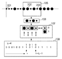
次に、図3を用いて、指標列から系列情報を求める動作について説明する。
指標列は、符号化により位置情報などがコード化された情報列を用いるが、その符号化の起点201が指標列には存在し、そこから一連の指標が等間隔で並んでいるものとする。撮像画像取得部105が取得した画像データ中には、このような指標列のうち、指標202から203までの直線上に並んでいる指標が撮像されているものとする。なお、ここでは、指標全体が撮像されている場合に”指標が撮像されている”と言う。
Next, the operation | movement which calculates | requires series information from an index sequence is demonstrated using FIG.
As the index string, an information string in which position information or the like is encoded by encoding is used, and the
特徴点検出部106では、画像データ中から指標の特徴量検出を用いて指標の領域を推定する。例として、指標の形状や色などをその特徴とすることも可能である。撮像画面中の各指標の位置は、特徴点検出部106において、指標の特徴情報を用いて検出した領域の重心を取ることによって1つの点として検出することが可能である。また、指標として検出された領域の外形枠を求め、外形枠の重心もしくは中心を求めても良い。さらに、指標を1次元に並べたときのデザイン(配置)が予め情報として分かっている場合には、指標列のベースラインからの相対値を特徴点検出部106が利用して指標の座標値を補正する方法でも構わない。
The feature
系列情報変換部107には、符号と指標の図形との対応が予め登録されており、特徴点検出部106から得られた指標の1つ1つに対して比較を行い、符号化に用いた時の位置情報に関連する数値情報へと変換する。例として、図3においては大きな円を数値情報”1”、小さな円を数値情報”0”にそれぞれ変換している。
Correspondence between codes and index figures is registered in series
カメラの撮像方向と指標列が布設されている壁面とが正対している環境においては、撮像画像中の指標列と参照用の図形(基準図形)との比較が容易に行える。しかし、一般的なカメラの位置姿勢計測においては、カメラの撮影方向と指標列が設けられた壁面との位置関係は任意であるため、指標列を斜めから撮影する場合が多い。 In an environment where the imaging direction of the camera and the wall surface on which the index row is laid face to face, the comparison between the index row in the captured image and the reference figure (standard figure) can be easily performed. However, in general camera position and orientation measurement, since the positional relationship between the shooting direction of the camera and the wall surface on which the index row is provided is arbitrary, the index row is often taken from an oblique direction.
図4(a)は、カメラ102が指標列200を斜めから撮影した状態を模式的に示す上面図である。カメラ102と指標列200を見下ろした状態を示し、指標列200が見えるように記載している。
FIG. 4A is a top view schematically showing a state in which the
図4(a)において、カメラ102は、北東の方角に向かって指標列200を撮影している。この場合、撮像画像105aには、図4(b)に示すように、指標列200が歪んで撮影される。この状態においては、指標列を構成する要素として大きさの異なる円を用いている場合は、それぞれの指標を区別することが難しい。そこで、指標列が外接する、頂点160乃至163で囲まれた領域に対して台形歪み補正を行うことにより、指標列の形状を安定して区別し、数値情報(系列情報)に変換することが可能となる。
In FIG. 4A, the
頂点160乃至163で囲まれた台形領域は元々長方形であり、指標列の布設方向における頂点162乃至161を結ぶ直線と頂点163乃至る160を結ぶ直線の2本の直線は平行である。さらに領域に含まれる指標列の個数を、直線に対して垂直方向への射影とする射影特徴から推定することで、物理的な指標列の間隔が既知であるため、長方形の長辺方向の長さと短辺方向の長さの比が求まる。長さの比が求められれば台形歪み補正を行うことができる。そのため、図4(c)の107aに示すように、撮像画像中の領域を長方形に補正することで、指標列を斜めから撮影した場合でも系列情報への変換が可能となる。
The trapezoidal region surrounded by the
さらに、カメラ102の光軸方向150と、指標列200が布設されている壁面の法線方向151と、指標列を構成する各指標の面積とが既知である。そのため、これらの情報を用いて指標列の領域を高精度に補正することも可能である。
Furthermore, the
得られた数値情報と符号化系列の情報との照合を行う系列情報照合部108において、照合位置を検出する。例として、符号化の基準長(L)が4である場合、指標202から203までに4点以上の指標が得られれば、変換された数値情報から符号列の照合が可能となる。基点からの照合開始位置をnとすると、終了位置はn+L−1となる。なお、M系列による符号化方法を用いれば、基準長Lが一致する周期を最大に取ることができるため、広範囲に指標列を布設する場合には有効である。M系列は、符号化の基準長(L)のシフトレジスタと、レジスタ出力のフィードバックによって周期が最大になるように構成される。
A collation position is detected by a sequence
なお、前述の系列情報照合部108は広範囲に対応するためにM系列を用いた場合を説明したが、指標列を布設する領域が狭い場合などは、符号列を格納したテーブルを参照して、数値情報をテーブル中で検出するようにしてもよい。
In addition, although the above-mentioned series
図5を用いて、起点情報取得部109及び系列指標相対座標演算部110の処理について説明する。
指標列の起点201に関する起点情報としては、現実空間における起点の座標位置(Px,Py,Pz)および指標列の起点からの方向成分(Vx,Vy,Vz)、さらに指標間の現実空間での長さ(d)が考えられる。なお、ここでは、方向成分(Vx,Vy,Vz)は現実空間での長さ(d)と同じ座標系で正規化しているものとする。
The processing of the starting point
The starting point information regarding the
起点情報取得部109は、系列情報照合部108で得られた情報から、関連する起点情報を得ることになるが、起点情報は予めテーブルなどに保持していてもよいし、起点情報を管理しているサーバなどに無線もしくは有線のネットワークを利用して問い合わせして取得しても構わない。
The starting point
起点情報取得部109から得られた起点情報から、系列指標相対座標演算部110では、カメラで撮影した画像に含まれる指標列の、現実空間での座標を計算する。例として、図3における指標202の現実空間での座標は、起点201の現実空間での座標(Px,Py,Pz)から(n)番目の指標として、指標間隔(d)の長さと起点からの方向(Vx,Vy,Vz)に配置されているものであるから、指標202の現実空間での座標は、(Px+d×n×Vx,Py+d×n×Vy,Pz+d×n×Vz)として求められる。
From the starting point information obtained from the starting point
起点201からの方向成分(Vx,Vy,Vz)に対する(n)番目の指標を、(Vx(n),Vy(n),Vz(n))と表現しても良い。方向成分に例えば正弦波を含めることで、指標列を正弦波状に設置すること(正弦波状に配置された指標列に対する座標を求めること)が可能となる。また、n番目の指標の座標を予めテーブルに登録しておき、テーブルを参照して座標を求めることも可能である。
The (n) th index for the direction component (Vx, Vy, Vz) from the
起点情報取得部109では、一般的な環境での実施形態を説明したが、系列情報照合部108での照合位置と指標列の現実空間の座標値を保持する1つ以上のテーブルとの対応を取ることにより、座標値を効率的に求めることも可能である。この場合は、系列指標相対座標演算部110の処理を省くことができる。
In the origin
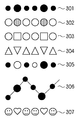
図6に指標列の例を示す。指標列301は基本的な図形を円として、例えば、大きい円=”1”、小さい円=”0”のように、大きさに応じた値を割り当てたものである。あるいは、”1”や”0”という値を、指標列の大きさで表現した指標列であると考えることもできる。
このように、本実施形態では、画像処理により識別可能な特徴において異なる複数種の指標を用い、符号列のような数値情報を画像情報に変換する。
FIG. 6 shows an example of the index string. The
As described above, in the present embodiment, numerical information such as a code string is converted into image information by using a plurality of types of indexes that differ in features that can be identified by image processing.
指標列302は、基本的な図形を円として、色の違う指標を用いた例である。指標列303は、基本的な図形が円と四角の指標を用いた例である。指標列304は、基本的な図形を三角形とし、その方向が異なる指標を用いた例である。指標列305は、異なる2つの特徴を有する指標を用いた例であり、基本的な図形を円とし、大きさ又は色とが異なる指標を用いた例である。
The index column 302 is an example in which indices having different colors are used with a basic figure as a circle. The
指標列305は、白い円形で大きさの異なる2種類の指標(分類1)と、黒い円形で大きさの異なる2種類の指標(分類2)の、2つの指標分類が混在したものと考えることができる。従って、分類1と分類2とで異なる情報を表すように構成することも可能である。この場合、数値情報への変換時に分類1と分類2を別個に取り扱うことで、指標列305には分類1が表す情報(例えば本来の数値情報)と分類2が表す情報(例えば誤り訂正情報)とが多重化されているものとして処理可能である。もちろん、指標列305で1つの情報を表すようにしてもよい。その場合、4種類の指標が含まれることから、1種類当たりの情報量を1ビット(”1”又は”0”)から2ビット(”00”、”01”、”10”、”11”のいずれか)とすることができる。そのため、同じ数値情報を表すのに必要な指標の数を減らすことが可能となる。
The
指標列306は、指標の種類は指標列301と共通であるが、直線状ではなく規則的な三角波状に配置させたものである。予め三角波の形状(角度や一辺の長さ)を登録しておくことで、このような非直線状の配置も可能となる。指標列307は基本的な図形(外形)が異なる指標という点では指標列303と共通であるが、外形をより複雑な形状としたものである。
The
これらの例のように、本実施形態では、少なくも画像処理により識別可能な特徴が異なる2種類以上の指標から構成すればよい。そのため、従来用いられていた、バーコードなどの2次元パターンを有する大型の指標よりも小型の指標を用いることができる。また、見た目にも違和感のない指標が使用できる。 As in these examples, in the present embodiment, at least two types of indicators having different features that can be identified by image processing may be used. For this reason, it is possible to use a smaller index than a conventionally used large index having a two-dimensional pattern such as a barcode. In addition, it is possible to use an index that does not seem strange to the eye.
多重化は、必要な基準長(L)が長くなった場合に、実際に検出しなくてはならない指標列を短くする効果がある。なお、図に示す指標は理論的に画像処理で識別可能な特徴を異ならせた指標の例を示したものである。実際に用いる指標についての基本的な図形の大きさ、色や濃度などは、実環境(特に光源の種類や明るさ)、撮像部並びに画像処理の性能などを考慮に入れて決定する必要がある。 Multiplexing has the effect of shortening the index string that must actually be detected when the required reference length (L) becomes long. The index shown in the figure is an example of an index that has different features that can be theoretically identified by image processing. The basic figure size, color, density, etc. for the indicators to be used must be determined in consideration of the actual environment (especially the type and brightness of the light source), the imaging unit and the image processing performance. .
さらに、符号化の基準長(L)が1つのまとまりとして撮像されれば、その開始、終了位置の2点が求まることから、全ての指標が等間隔で連続して配置されている必要はない。つまり、基準長(L)に対応する1つの指標列から、別の指標列までの間に、空白の部分や他の符号化による指標列が入っていたとしても構わない。 Further, if the encoding reference length (L) is imaged as one unit, two points of the start and end positions can be obtained, and therefore it is not necessary that all indexes are continuously arranged at equal intervals. . That is, there may be a blank portion or another encoded index sequence between one index sequence corresponding to the reference length (L) and another index sequence.
また、指標によって表す符号列には、複数の情報を持たせても良い(多重符号化系列)。具体的には、現実空間の指標列の基準点や起点の参照点に関する情報を多重符号化して指標列で表すことで、前述の起点情報取得部109での情報として使うことができる。また、画像処理での検出誤りが発生する場合もあるので、誤りを訂正もしくは検出する情報を多重符号化して指標列の情報に含めることで、情報の検出を安定させる効果がある。
Also, the code string represented by the index may have a plurality of pieces of information (multiplex encoded sequence). Specifically, information regarding the reference point of the index string in the real space and the reference point of the starting point is multiplex-coded and expressed as an index string, which can be used as information in the above-described starting point
さらに、指標列の周辺の地理的な情報、例えば地名や公共施設の場所などに関する情報を符号化情報に持たせることで、カメラ102の位置姿勢を検出した後にナビゲーションの工程などに利用することも可能である。
Further, by providing the encoded information with geographical information around the index string, for example, information on place names and public facilities, the information can be used for a navigation process after detecting the position and orientation of the
引き続いて、図7に示すフローチャートを参照して、本実施形態に係る位置姿勢計測装置100の動作について説明する。
ステップS101とステップS102は並列に実行される。ステップS101では、姿勢センサ103からカメラ102の姿勢を取得する。姿勢センサ103は、位置姿勢計測装置100とは独立して情報が更新されているため、ステップS101にて最新の更新状態を取得する。
Subsequently, the operation of the position /
Step S101 and step S102 are executed in parallel. In step S <b> 101, the posture of the
ステップS102では、カメラ102から映像を撮像画像取得部105にて取得する処理を実行する。カメラ102は、所定のフレームレート(例えば30フレーム/秒)で動画像を撮像しつづけている。そして、撮像画像取得部105は、ステップS102で、この連続したフレームの1フレーム分の画像信号を取得し、デジタルデータへの変換などを行い画像データを生成する。
In step S <b> 102, processing for acquiring a video from the
ステップS103では、特徴点検出部106にて、ステップS102で生成された画像データ中に指標列が含まれているかどうかを検出する。検出の結果、画像データ中に指標列が含まれていない場合(ステップS104,No)は、指標の現実空間における座標が求まらないため、カメラ102の位置姿勢推定が出来ない。そこで、過去の複数の検出結果から、カメラ姿勢の変化分を推定して、姿勢回転による補正のみを行う(ステップS112)。例えば、直近の2つ以上の検出結果から、カメラ姿勢の変化を推定することができる。
In step S103, the feature
一方、画像データ中に指標列が検出された場合(ステップS104,Yes)は、図4に示したような台形歪み補正処理を行う。(ステップS105)。台形歪み補正は、姿勢センサ103で検出されるカメラ102の姿勢から求まる撮影方向と、指標列が配置された壁面の法線が既知であることを利用して行うことができる。なお、指標が設けられた壁面の法線が未知の場合や、カメラ102の撮影方向が未知であっても、撮像された指標列の外接四角形が長方形となるように補正を行うことで台形歪み補正処理を行うことが可能である。なお、指標列が直線状に配置されていない場合でも、既知の配置情報と指標の外接形状とを用いて補正を行うことが可能である。
On the other hand, when the index string is detected in the image data (step S104, Yes), the trapezoidal distortion correction process as shown in FIG. 4 is performed. (Step S105). The trapezoidal distortion correction can be performed by using the photographing direction obtained from the posture of the
台形歪み補正処理を行った撮像画像を用い、ステップS106では、系列情報変換部107により、指標列から数値情報への変換を行う。そして、ステップS107で、系列情報照合部108により、予め定めた符号列(系列情報)と、数値情報(数値列)との照合を行う。具体的には、数値列が符号列中に存在するかどうか、存在する場合にはその位置はどこかを検出する。なお、図6の指標列の例として示したように、画像処理により検出可能な指標の特徴を複数の組み合わせた指標列を用い、指標列に複数の符号化情報を持たせる多重符号化技術を用いることができる。そして、符号化に関する誤り検出もしくは誤り訂正などの情報を付加情報として指標列が表す情報に付加することにより、系列情報照合部108における処理の検出精度を向上することも可能である。
In step S106, the series
ステップS107での照合の結果、数値情報が系列情報に合致したかどうかを判別する(ステップS108)。合致部分が無い場合は、利用する範囲の指標列では無い場合か、もしくは指標列の誤検出による場合などがある。照合が不成功に終わった場合は、ステップS104で指標列が検出されなかった場合と同様に、ステップS112で過去の検出結果から姿勢の変化分を推定し、補正を行う。 As a result of the collation in step S107, it is determined whether or not the numerical information matches the series information (step S108). When there is no matching part, there is a case where the index string is not in the range to be used, or a case where the index string is erroneously detected. If the verification is unsuccessful, in the same manner as when the index string is not detected in step S104, the change in posture is estimated from the past detection result in step S112, and correction is performed.
一方、数値情報が系列情報中で合致する部分が検出されたら(ステップS108、Yes)、起点情報取得部109で符号化の起点情報(起点位置の現実空間における座標値等)を取得する(ステップS109)。起点情報取得部109では、ネットワーク上のサーバに対して、参照点および位置に関する情報を問い合わせも良いし、指標列に多重化された符号化情報を用いて、起点に関する情報を取得しても良い。
On the other hand, when a portion where the numerical information matches in the series information is detected (Yes in step S108), the starting point
ステップS110では、系列指標相対座標演算部110が、ステップS103にて検出された指標列の現実空間での座標を演算する。すなわち、指標の配置に関する既知の情報(ここでは、起点情報取得部109から得た起点情報と、指標の配置方向及び指標間隔に関する情報)と、数値情報が系列情報中で現れる位置の情報とを用いて上述のように各指標の座標を計算する。なお、指標が設けられた壁面の法線についての情報や、画像処理により識別可能な指標の特徴(形状や色など)も指標の配置に関する既知の情報に含まれる。
In step S110, the series index relative coordinate
起点からの指標列の方向を示すベクトル(Vx、Vy、Vz)および指標間の距離(d)は、照合位置(n)に関する関数として扱うこともできる。この場合、方向成分として(Vx(n)、Vy(n)、Vz(n))および距離(d(n))として表現される。上述のように、関数表記を用いる場合には、方向成分に三角関数などを導入することで、指標列を曲線状に配置することも可能となる。また、起点201の現実空間での座標は必ずしも絶対位置である必要はなく、他の指標からの相対位置でも構わないし、位置姿勢推定を行う領域で既知の位置としても良い。
The vector (Vx, Vy, Vz) indicating the direction of the index string from the starting point and the distance (d) between the indices can also be handled as a function related to the collation position (n). In this case, (Vx (n), Vy (n), Vz (n)) and a distance (d (n)) are expressed as direction components. As described above, when function notation is used, the index string can be arranged in a curved line by introducing a trigonometric function or the like into the direction component. Further, the coordinates of the
ステップS111では、
・ステップS110で現実空間での位置が求められた2点以上の指標に関する現実空間での座標
・これら2点以上の指標の画像画面上の座標(ステップS102で検出済み)
・姿勢センサ103で検出されたカメラの姿勢(ステップS101で検出済み)
を用いて、カメラの位置情報を未知数とする線形連立方程式を解法して、カメラの位置姿勢を推定する。
In step S111,
-Coordinates in the real space relating to the two or more indicators whose positions in the real space have been obtained in step S110-Coordinates on the image screen of these two or more indicators (detected in step S102)
Camera posture detected by posture sensor 103 (detected in step S101)
Is used to solve the linear simultaneous equation with the camera position information as an unknown, and the camera position and orientation are estimated.
ここで、線形連立方程式からカメラの位置姿勢を求める工程を説明する。まず、指標列が設置されている現実空間を示す世界座標系(Xとする)と、カメラ102を中心としたカメラ座標系(xとする)との関係について述べる。世界座標系Xの座標からカメラ座標系xの座標への座標変換は、カメラ座標系xから見た世界座標系Xの原点の位置を表す3次元ベクトルt、およびカメラ座標系xから見た世界座標系Xの姿勢を表す回転変換行列Rを用いて、
x=RX+t ・・・(1)
と表せる。
Here, the process of obtaining the position and orientation of the camera from the linear simultaneous equations will be described. First, the relationship between the world coordinate system (X) indicating the real space where the index string is installed and the camera coordinate system (X) centered on the
x = RX + t (1)
It can be expressed.
カメラ座標系xでの指標位置から、カメラの撮像面へ投影された指標位置を求める変換を透視変換と呼ぶ。ここで、カメラの光軸と撮像面の中心が一致しているとして、水平方向の焦点距離をfx、垂直方向の焦点距離をfyとすると、カメラ座標系xでの指標の位置x=[xc,yc,zc]tは、透視変換によって撮像面の2次元画像座標u=[ux,uy]に投影される。 The conversion for obtaining the index position projected on the imaging surface of the camera from the index position in the camera coordinate system x is called perspective transformation. Here, assuming that the optical axis of the camera coincides with the center of the imaging surface, assuming that the horizontal focal length is fx and the vertical focal length is fy, the index position x = [x in the camera coordinate system x c , y c , z c ] t is projected onto the two-dimensional image coordinates u = [u x , u y ] on the imaging surface by perspective transformation.

ここで、カメラ座標系xにおける世界座標系Wの位置をt=[tx,ty,tz]tとおき、回転変換行列Rを3×3の行列式として Here, the position of the world coordinate system W in the camera coordinate system x is set as t = [t x , t y , t z ] t , and the rotation transformation matrix R is defined as a 3 × 3 determinant.
とおくと、式(1)、(2)、(3)より、世界座標系での位置がX=[xw,yw,zw]tである点は、透視投影変換によって2次元画像座標u=[ux,uy]に投影されるので、以下の式を満たす。 Then, from the equations (1), (2), (3), the point in the world coordinate system where X = [x w , y w , z w ] t is converted into a two-dimensional image by perspective projection transformation. Since it is projected to the coordinates u = [u x , u y ], the following expression is satisfied.
さらに、u'x=−ux/fx,u'y=−uy/fyとおくと、式(4)は Furthermore, if u ′ x = −u x / f x and u ′ y = −u y / f y , then Equation (4) becomes
と表せる。カメラの姿勢計測で重力軸方向に対する2方向の傾斜および地軸に対する方位成分の3つの成分が得られた場合、世界座標系におけるカメラの姿勢を既知とすることができるので、回転変換行列Rも同様に既知となる。よって、式(5)からカメラの位置であるt=[tx,ty,tz]tに関して左辺にまとめると、 It can be expressed. When the camera orientation measurement obtains three components, the tilt in two directions with respect to the gravitational axis direction and the azimuth component with respect to the ground axis, the camera orientation in the world coordinate system can be known, so the rotation transformation matrix R is the same. Become known. Therefore, from the equation (5), t = [t x , t y , t z ] t that is the camera position is summarized on the left side.
と表せる。
未知変数はt=[tx,ty,tz]tであるので、撮像画像における指標の2次元画像座標u'=[u'x,u'y]が2個以上あれば式(6)の連立方程式を解くことによってt=[tx,ty,tz]tが求まる。さらに式(7)よりカメラの世界座標系での位置tw=[twx,twy,twz]が得られる。
It can be expressed.
Since the unknown variable is t = [t x , t y , t z ] t , if there are two or more two-dimensional image coordinates u ′ = [u ′ x , u ′ y ] of the index in the captured image, the expression (6 ) To obtain t = [t x , t y , t z ] t . Further, the position t w = [t wx , t wy , t wz ] in the world coordinate system of the camera is obtained from the equation (7).
以上説明したように、本実施形態によれば、予め定めた符号列を、連続する複数の指標で表す様に指標を配置する。指標列を構成する指標は画像処理で識別可能な特徴が異なる少なくとも2種類の指標を含む。そして、撮像画像中に検出された指標を数値情報に変換し、数値情報と予め定めた符号列とから、撮像画像中に検出された指標の同定を行う。そして、予め登録された基準となる指標の座標情報を用いて、同定された指標の座標情報を求める。この座標情報と、別途取得したカメラの姿勢情報とを用い、カメラの位置姿勢を求める。 As described above, according to the present embodiment, indexes are arranged so that a predetermined code string is represented by a plurality of continuous indexes. The indices constituting the index string include at least two kinds of indices having different features that can be identified by image processing. Then, the index detected in the captured image is converted into numerical information, and the index detected in the captured image is identified from the numerical information and a predetermined code string. Then, the coordinate information of the identified index is obtained by using the coordinate information of the index as a reference registered in advance. Using this coordinate information and separately acquired camera posture information, the camera position and posture are obtained.
本実施形態では指標の種別が画像から特定できれば良いため、バーコードなど複雑な2次元画像パターンを指標に持たせ、それを認識する必要がある場合と比べると、小型の指標を用いることが可能であり、現実空間に布設した際の違和感を低減することが可能となる。また、指標が壁面の模様として認識される可能性が高くなり、やはり違和感を低減することが可能となる。 In this embodiment, since it is only necessary to identify the index type from the image, it is possible to use a small index as compared with the case where it is necessary to recognize and recognize a complicated two-dimensional image pattern such as a barcode. Therefore, it is possible to reduce a sense of incongruity when laying in a real space. In addition, the possibility that the index is recognized as a pattern on the wall surface is increased, and it is possible to reduce the uncomfortable feeling.
さらに、位置姿勢計測装置のみで撮像装置の位置姿勢を計測することが可能となり、広範囲でのカメラの位置姿勢を求めることができる。加えて、6自由度センサを用いる必要がないため、6自由度センサの計測範囲の問題、設置の問題、価格の問題を解決することができる。 Furthermore, it becomes possible to measure the position and orientation of the imaging apparatus only with the position and orientation measurement apparatus, and the position and orientation of the camera in a wide range can be obtained. In addition, since it is not necessary to use a 6-degree-of-freedom sensor, it is possible to solve the measurement range problem, installation problem, and price problem of the 6-degree-of-freedom sensor.
(他の実施形態)
上述の実施形態においては、1つの機器から構成される位置姿勢計測装置についてのみ説明したが、同等の機能を複数の機器から構成されるシステムによっても実現しても良い。
(Other embodiments)
In the above-described embodiment, only the position / orientation measurement apparatus configured by one device has been described. However, an equivalent function may be realized by a system configured by a plurality of devices.
上述の実施形態においては、本発明による位置姿勢計測装置をHMDに設けたカメラの位置姿勢検出に適用した場合のみを説明した。しかし、本発明による位置姿勢計測装置は、現実空間の指標列を撮像する装置とカメラの姿勢を検出する装置の2つの装置があり、互いの位置が固定されていれば良い。例としては、カメラと姿勢センサを有する携帯電話等に本発明を実施するプログラムを実行させても同じ効果が得られる。 In the above-described embodiment, only the case where the position / orientation measurement apparatus according to the present invention is applied to the position / orientation detection of the camera provided in the HMD has been described. However, the position / orientation measurement apparatus according to the present invention includes two apparatuses, that is, an apparatus that captures an index string in real space and an apparatus that detects the attitude of the camera , and it is only necessary that the position of each other is fixed. As an example, the same effect can be obtained by causing a mobile phone or the like having a camera and a posture sensor to execute a program for carrying out the present invention.
また、上述の実施形態においては、検出対象となるカメラの姿勢を検出する姿勢センサを用いた場合のみを説明したが、姿勢を直接検出する必要はない。少なくとも過去に求めた位置姿勢から現時点の位置姿勢を推定可能な情報(例えば姿勢の変化量)が得られれば、姿勢センサに限らず任意のセンサを利用しうる。これら情報を姿勢情報と呼ぶ。 In the above-described embodiment, only the case where the posture sensor that detects the posture of the camera to be detected is used has been described. However, it is not necessary to directly detect the posture. If information that can estimate the current position and orientation (for example, the amount of change in posture) can be obtained from at least the position and orientation obtained in the past, any sensor can be used instead of the orientation sensor. These pieces of information are called posture information.
例として、位置関係が固定の別の撮像装置により、カメラに鉛直方向もしくは、その方向が既知の指標を撮影してその位置からカメラの姿勢を求めることも可能である。同様に、カメラ102が撮像した画像中にその指標が含まれている場合も、同じように処理することが可能である。
As an example, it is possible to capture the camera in the vertical direction or an index whose direction is known by another imaging device having a fixed positional relationship and obtain the posture of the camera from the position. Similarly, when the index is included in an image captured by the
また、カメラの姿勢を検出する、現実空間に設置された別の装置を用いて、カメラの姿勢だけを検出することも可能である。例として、カメラの光軸との対応が既知の指標(姿勢検出用指標)を設置し、その指標を現実空間に設置された別の撮像装置で撮像して、画像処理を用いて姿勢を求めることが可能である。 Further, to detect the posture of the camera, using another device installed in the physical space, it is possible to detect only the orientation of the camera. As an example, an index (attitude detection index) whose correspondence with the optical axis of the camera is known is set, the index is captured by another imaging device installed in the real space, and the attitude is obtained using image processing. It is possible.
また、カメラがアームなどで支持されている場合は、アームの関節角度の値からカメラの姿勢を求めることもできる。さらに、複数の姿勢検出結果を組み合わせて姿勢の測定精度を向上させることも可能である。 Further, when the camera is supported by an arm or the like, the posture of the camera can be obtained from the value of the joint angle of the arm. Furthermore, it is possible to improve posture measurement accuracy by combining a plurality of posture detection results.
さらに、上述の実施形態において、より精度が必要となる固定された領域と、移動中でのそれほど精度が必要でない領域とで、精度の異なる複数の位置姿勢計測方法を切り替えて使用する構成でも構わない。 Furthermore, in the above-described embodiment, a configuration may be used in which a plurality of position / orientation measurement methods having different accuracy are switched between a fixed region where higher accuracy is required and a region where movement is not required so much. Absent.
上述の実施形態においては指標列が1列のみ配置されている条件で説明したが、環境中に複数列設置してもよい。さらに、カメラにより、それらの指標列が複数検出された場合、それらを複数用いて処理を行っても位置姿勢計測を実現することができる。 In the above-described embodiment, description has been made on the condition that only one index row is arranged, but a plurality of rows may be installed in the environment. Furthermore, when a plurality of such index strings are detected by the camera , position and orientation measurement can be realized even if processing is performed using a plurality of such index strings.
また、上述の実施形態は、システム或は装置のコンピュータ(或いはCPU、MPU等)によりソフトウェア的に実現することも可能である。
従って、本発明の機能処理をコンピュータで実現するために、該コンピュータに供給、インストールされるコンピュータプログラム自体も本発明を実現するものである。つまり、本発明の機能処理を実現するためのコンピュータプログラム自体も本発明に含まれる。
Further, the above-described embodiment can be realized by software by a computer of a system or apparatus (or CPU, MPU, etc.).
Accordingly, the computer program itself supplied and installed in the computer in order to implement the functional processing of the present invention by the computer also realizes the present invention. That is, the computer program itself for realizing the functional processing of the present invention is also included in the present invention.
その場合、プログラムの機能を有していれば、オブジェクトコード、インタプリタにより実行されるプログラム、OSに供給するスクリプトデータ等、プログラムの形態を問わない。 In this case, the program may be in any form as long as it has a program function, such as an object code, a program executed by an interpreter, or script data supplied to the OS.
この場合、本発明の機能処理をコンピュータで実現するためのコンピュータプログラムは、記憶媒体又は有線/無線通信によりコンピュータに供給される。プログラムを供給するための記録媒体としては、例えば、フレキシブルディスク、ハードディスク、磁気テープ等の磁気記録媒体、MO、CD、DVD等の光/光磁気記憶媒体、不揮発性の半導体メモリなどがある。 In this case, a computer program for realizing the functional processing of the present invention by a computer is supplied to the computer by a storage medium or wired / wireless communication. Examples of the recording medium for supplying the program include a magnetic recording medium such as a flexible disk, a hard disk, and a magnetic tape, an optical / magneto-optical storage medium such as an MO, CD, and DVD, and a nonvolatile semiconductor memory.
有線/無線通信を用いたプログラムの供給方法としては、コンピュータネットワーク上のサーバを利用する方法がある。この場合、本発明を形成するコンピュータプログラムとなりうるデータファイル(プログラムデータファイル)をサーバに記憶しておく。プログラムデータファイルとしては、実行形式のものであっても、ソースコードであっても良い。 As a program supply method using wired / wireless communication, there is a method of using a server on a computer network. In this case, a data file (program data file) that can be a computer program forming the present invention is stored in the server. The program data file may be an executable format or a source code.
そして、このサーバにアクセスしたクライアントコンピュータに、プログラムデータファイルをダウンロードすることによって供給する。この場合、プログラムデータファイルを複数のセグメントファイルに分割し、セグメントファイルを異なるサーバに分散して配置することも可能である。
つまり、本発明の機能処理をコンピュータで実現するためのプログラムデータファイルをクライアントコンピュータに提供するサーバ装置も本発明に含む。
Then, the program data file is supplied by downloading to a client computer that has accessed the server. In this case, the program data file can be divided into a plurality of segment files, and the segment files can be distributed and arranged on different servers.
In other words, the present invention includes a server device that provides a client computer with a program data file for realizing the functional processing of the present invention on a computer.
また、本発明のコンピュータプログラムを暗号化して格納した記憶媒体をユーザに配布し、所定の条件を満たしたユーザに、暗号化を解く鍵情報を供給し、ユーザの有するコンピュータへのインストールを可能とすることも可能である。鍵情報は例えばインターネットを介してホームページからダウンロードさせることによって供給することができる。 In addition, a storage medium in which the computer program of the present invention is encrypted and stored is distributed to users, key information for decryption is supplied to users who satisfy predetermined conditions, and installation on a user's computer is possible It is also possible to do. The key information can be supplied by downloading from a homepage via the Internet, for example.
また、コンピュータにより実施形態の機能を実現するためのコンピュータプログラムが、実施形態の機能を、すでにコンピュータ上で稼働するOSの機能を利用して実現しても良い。 In addition, a computer program for realizing the functions of the embodiments by a computer may realize the functions of the embodiments by using the functions of an OS already running on the computer.
さらに、本発明を構成するコンピュータプログラムの少なくとも一部が、コンピュータに装着される拡張ボード等のファームウェアとして提供され、拡張ボード等が備えるCPUを利用して上述の実施形態の機能を実現しても良い。 Further, at least a part of the computer program constituting the present invention is provided as firmware such as an expansion board attached to the computer, and the functions of the above-described embodiments can be realized using a CPU provided in the expansion board. good.
Claims (9)
取得手段が、前記撮像装置の姿勢情報を取得する姿勢情報取得工程と、
検出手段が、前記撮像装置で撮像された画像から複数の指標を検出し、該検出された指標の各々の画像座標を取得する指標検出工程と、
変換手段が、前記指標検出工程で検出された複数の指標を対応する系列情報に変換する変換工程と、
照合手段が、前記一次元的に所定の間隔で布設された複数の指標に対応する符号列中における、前記系列情報と合致する部分を検出する照合工程と、
座標算出手段が、前記系列情報と合致する部分の前記符号列中における位置と、前記起点の現実空間での座標と、前記所定の方向と、前記所定の間隔とを用いて、前記検出された指標の各々の現実空間における座標を求める座標算出工程と、
位置姿勢算出手段が、前記姿勢情報と、前記座標算出工程で求めた座標と、前記画像座標とを用いて、前記撮像装置の3次元位置姿勢を算出する位置姿勢算出工程とを有することを特徴とする位置姿勢計測方法。 This is a position and orientation measurement method for measuring the position and orientation of an imaging apparatus that images a real space in which a plurality of indices are laid out one-dimensionally at a predetermined interval from a starting point whose coordinates in the real space are known. And
An acquisition unit that acquires attitude information of the imaging apparatus;
An index detecting step for detecting a plurality of indices from an image captured by the imaging device, and obtaining image coordinates of each of the detected indices;
A converting unit that converts a plurality of indices detected in the index detecting process into corresponding series information; and
A matching step of detecting a portion that matches the sequence information in a code string corresponding to a plurality of indices laid out at predetermined intervals in the one-dimensional manner ;
Coordinate calculating means, a position in the numeral sequence of a portion that matches with the sequence information, the coordinates in the real space of the starting point, and the predetermined direction, using said predetermined distance, which is the detected a coordinate calculation step of calculating coordinates of each of the real space of the index,
Position and orientation calculation unit, and the posture information, the coordinates obtained in the coordinate calculation step, by using the said image coordinates, to have a position and orientation calculation step of calculating a three-dimensional position and orientation of the imaging device A characteristic position and orientation measurement method.
前記変換工程が、前記補正を行った後の画像を用いて前記変換を行うことを特徴とする請求項1記載の位置姿勢計測方法。 The correction unit further includes a correction step of correcting distortion of the image area including the plurality of indexes detected in the index detection step,
The position / orientation measurement method according to claim 1, wherein the conversion step performs the conversion using an image after the correction.
前記撮像装置の姿勢情報を取得する姿勢情報取得手段と、
前記撮像装置で撮像された画像から複数の指標を検出し、該検出された指標の画像座標を取得する指標検出手段と、
前記指標検出手段で検出された複数の指標を、対応する系列情報に変換する変換手段と、
前記一次元的に所定の間隔で布設された複数の指標に対応する符号列中における、前記系列情報と合致する部分を検出する照合手段と、
前記系列情報と合致する部分の前記符号列中における位置と、前記起点の現実空間での座標と、前記所定の方向と、前記所定の間隔とを用いて、前記検出された指標の各々の現実空間における座標を求める座標算出手段と、
前記姿勢情報と、前記座標算出手段が求めた座標と、前記画像座標とを用いて、前記撮像装置の3次元位置姿勢を算出する位置姿勢算出手段とを有することを特徴とする位置姿勢計測装置。 There by the position and orientation measurement apparatus coordinates in the real space to measure the position and orientation of an imaging apparatus for imaging a real space, which is laid in a plurality of indicators in a predetermined one-dimensionally apart from the origin is known in a predetermined direction And
Attitude information acquisition means for acquiring attitude information of the imaging device;
Index detecting means for detecting a plurality of indices from an image captured by the imaging device and acquiring image coordinates of the detected indices;
Conversion means for converting a plurality of indices detected by the index detection means into corresponding series information;
Collating means for detecting a portion that matches the sequence information in a code string corresponding to a plurality of indices laid out at a predetermined interval in a one-dimensional manner ;
A position in the numeral sequence of a portion that matches with the sequence information, the coordinates in the real space of the starting point, and the predetermined direction, using said predetermined distance, real each of the detected indices and coordinate calculating means for determining the coordinates in space,
And the posture information, the coordinates of the coordinate calculation means is determined, by using the said image coordinates, the position and orientation measurement, characterized in that it comprises a position and orientation calculation means for calculating a three-dimensional position and orientation of the imaging device apparatus.
Priority Applications (3)
| Application Number | Priority Date | Filing Date | Title |
|---|---|---|---|
| JP2006100382A JP5084167B2 (en) | 2006-03-31 | 2006-03-31 | Position and orientation measurement method and apparatus |
| US12/294,324 US8335400B2 (en) | 2006-03-31 | 2007-03-23 | Information processing method and information processing apparatus |
| PCT/JP2007/057028 WO2007114313A1 (en) | 2006-03-31 | 2007-03-23 | Information processing method and information processing apparatus |
Applications Claiming Priority (1)
| Application Number | Priority Date | Filing Date | Title |
|---|---|---|---|
| JP2006100382A JP5084167B2 (en) | 2006-03-31 | 2006-03-31 | Position and orientation measurement method and apparatus |
Publications (3)
| Publication Number | Publication Date |
|---|---|
| JP2007271563A JP2007271563A (en) | 2007-10-18 |
| JP2007271563A5 JP2007271563A5 (en) | 2009-05-14 |
| JP5084167B2 true JP5084167B2 (en) | 2012-11-28 |
Family
ID=38563580
Family Applications (1)
| Application Number | Title | Priority Date | Filing Date |
|---|---|---|---|
| JP2006100382A Expired - Fee Related JP5084167B2 (en) | 2006-03-31 | 2006-03-31 | Position and orientation measurement method and apparatus |
Country Status (3)
| Country | Link |
|---|---|
| US (1) | US8335400B2 (en) |
| JP (1) | JP5084167B2 (en) |
| WO (1) | WO2007114313A1 (en) |
Families Citing this family (40)
| Publication number | Priority date | Publication date | Assignee | Title |
|---|---|---|---|---|
| JP5230114B2 (en) * | 2007-03-13 | 2013-07-10 | キヤノン株式会社 | Information processing apparatus and information processing method |
| US8121389B2 (en) * | 2008-06-11 | 2012-02-21 | Sirona Dental Systems Gmbh | System, apparatus, method and computer program product for optical position recognition |
| US8290240B2 (en) * | 2008-06-11 | 2012-10-16 | Sirona Dental Systems Gmbh | System, apparatus, method, and computer program product for determining spatial characteristics of an object using a camera and a search pattern |
| US8957835B2 (en) | 2008-09-30 | 2015-02-17 | Apple Inc. | Head-mounted display apparatus for retaining a portable electronic device with display |
| JP5319478B2 (en) * | 2009-09-30 | 2013-10-16 | 株式会社昭特製作所 | Method for calculating position of camera device |
| JP5728159B2 (en) | 2010-02-02 | 2015-06-03 | ソニー株式会社 | Image processing apparatus, image processing method, and program |
| WO2011106900A1 (en) | 2010-03-05 | 2011-09-09 | Poirier Frederic | Verification system for prescription packaging and method |
| EP2548179A4 (en) * | 2010-03-17 | 2013-10-16 | Sony Corp | Information processing device, information processing method, and program |
| US8908043B2 (en) * | 2010-04-12 | 2014-12-09 | Symbol Technologies, Inc. | System and method for location-based operation of a head mounted display |
| JP2012034196A (en) * | 2010-07-30 | 2012-02-16 | Olympus Corp | Imaging terminal, data processing terminal, imaging method, and data processing method |
| JP4763847B1 (en) * | 2010-08-30 | 2011-08-31 | 楽天株式会社 | Image conversion apparatus, image processing apparatus, and image processing system |
| JP5697487B2 (en) * | 2011-02-25 | 2015-04-08 | 任天堂株式会社 | Image processing system, image processing method, image processing apparatus, and image processing program |
| US10972680B2 (en) | 2011-03-10 | 2021-04-06 | Microsoft Technology Licensing, Llc | Theme-based augmentation of photorepresentative view |
| CN102222333B (en) * | 2011-05-20 | 2013-01-02 | 同济大学 | Method and device of mobile augmented reality of underground engineering based on mixed registration |
| US10242456B2 (en) * | 2011-06-23 | 2019-03-26 | Limitless Computing, Inc. | Digitally encoded marker-based augmented reality (AR) |
| US9355451B2 (en) | 2011-08-24 | 2016-05-31 | Sony Corporation | Information processing device, information processing method, and program for recognizing attitude of a plane |
| JP6023415B2 (en) * | 2011-10-17 | 2016-11-09 | キヤノン株式会社 | Three-dimensional measuring apparatus, control method and program for three-dimensional measuring apparatus |
| JP5547227B2 (en) * | 2012-03-29 | 2014-07-09 | 株式会社デンソーアイティーラボラトリ | Imaging device position / posture estimation system |
| US9516223B2 (en) | 2012-06-06 | 2016-12-06 | Apple Inc. | Motion-based image stitching |
| US9071785B2 (en) * | 2013-02-15 | 2015-06-30 | Gradeable, Inc. | Adjusting perspective distortion of an image |
| JP6137910B2 (en) * | 2013-03-29 | 2017-05-31 | キヤノン株式会社 | Information processing apparatus, information processing method, and program |
| EP2797313A1 (en) | 2013-04-26 | 2014-10-29 | Elvesjö, John | Computer graphics presentation system and method |
| US9350916B2 (en) | 2013-05-28 | 2016-05-24 | Apple Inc. | Interleaving image processing and image capture operations |
| US9491360B2 (en) | 2013-06-06 | 2016-11-08 | Apple Inc. | Reference frame selection for still image stabilization |
| US9262684B2 (en) | 2013-06-06 | 2016-02-16 | Apple Inc. | Methods of image fusion for image stabilization |
| US9384552B2 (en) | 2013-06-06 | 2016-07-05 | Apple Inc. | Image registration methods for still image stabilization |
| US9542585B2 (en) | 2013-06-06 | 2017-01-10 | Apple Inc. | Efficient machine-readable object detection and tracking |
| US20150071547A1 (en) | 2013-09-09 | 2015-03-12 | Apple Inc. | Automated Selection Of Keeper Images From A Burst Photo Captured Set |
| JP2015055534A (en) * | 2013-09-11 | 2015-03-23 | 株式会社リコー | Information processing apparatus, control program thereof, and control method thereof |
| US9286725B2 (en) * | 2013-11-14 | 2016-03-15 | Nintendo Co., Ltd. | Visually convincing depiction of object interactions in augmented reality images |
| JP6344029B2 (en) * | 2014-04-16 | 2018-06-20 | 富士通株式会社 | Display method, display program, and display device |
| US9881378B2 (en) * | 2016-02-12 | 2018-01-30 | Vortex Intellectual Property Holding LLC | Position determining techniques using image analysis of marks with encoded or associated position data |
| US10499026B1 (en) * | 2016-06-27 | 2019-12-03 | Amazon Technologies, Inc. | Automation correction of projection distortion |
| JP2019068932A (en) * | 2017-10-06 | 2019-05-09 | 株式会社Nttドコモ | Visual line detection device and visual line detection program |
| JP6733127B2 (en) * | 2018-01-24 | 2020-07-29 | 株式会社建設システム | Information processing device, information processing method, and program |
| US10984600B2 (en) | 2018-05-25 | 2021-04-20 | Tiff's Treats Holdings, Inc. | Apparatus, method, and system for presentation of multimedia content including augmented reality content |
| US10818093B2 (en) | 2018-05-25 | 2020-10-27 | Tiff's Treats Holdings, Inc. | Apparatus, method, and system for presentation of multimedia content including augmented reality content |
| CN109579745A (en) * | 2018-11-26 | 2019-04-05 | 江苏科技大学 | Novel house Area computing method based on augmented reality and cell phone software |
| JP7141375B2 (en) * | 2019-09-05 | 2022-09-22 | 株式会社日立ビルシステム | measurement system |
| JP2023170050A (en) * | 2022-05-18 | 2023-12-01 | ミネベアミツミ株式会社 | Marker detection device, monitoring system, and methods therefor |
Family Cites Families (13)
| Publication number | Priority date | Publication date | Assignee | Title |
|---|---|---|---|---|
| JP3595579B2 (en) * | 1994-08-26 | 2004-12-02 | キヤノン株式会社 | Image processing apparatus and image processing method |
| JPH1184307A (en) | 1997-09-01 | 1999-03-26 | M R Syst Kenkyusho:Kk | Head-mounted optical device |
| JP3976900B2 (en) | 1998-07-23 | 2007-09-19 | キヤノン株式会社 | Method for determining viewpoint position and orientation and camera device |
| JP4282216B2 (en) * | 2000-09-19 | 2009-06-17 | オリンパス株式会社 | 3D position and orientation sensing device |
| US6697761B2 (en) * | 2000-09-19 | 2004-02-24 | Olympus Optical Co., Ltd. | Three-dimensional position/orientation sensing apparatus, information presenting system, and model error detecting system |
| US20030076980A1 (en) * | 2001-10-04 | 2003-04-24 | Siemens Corporate Research, Inc.. | Coded visual markers for tracking and camera calibration in mobile computing systems |
| JP2003281504A (en) * | 2002-03-22 | 2003-10-03 | Canon Inc | Image pickup portion position and attitude estimating device, its control method and composite reality presenting system |
| JP4532856B2 (en) * | 2003-07-08 | 2010-08-25 | キヤノン株式会社 | Position and orientation measurement method and apparatus |
| JP4593968B2 (en) * | 2004-05-14 | 2010-12-08 | キヤノン株式会社 | Position and orientation measurement method and apparatus |
| JP2005337870A (en) * | 2004-05-26 | 2005-12-08 | Kyoto Univ | Detection system and labeled object |
| JP2005351869A (en) * | 2004-06-14 | 2005-12-22 | Yokohama Tlo Co Ltd | Positioning method and system |
| JP2007010335A (en) | 2005-06-28 | 2007-01-18 | Fujitsu Ltd | Vehicle position detecting device and system |
| US20090109453A1 (en) * | 2007-10-24 | 2009-04-30 | Kabushiki Kaisha Toshiba | Image forming apparatus and image forming method |
-
2006
- 2006-03-31 JP JP2006100382A patent/JP5084167B2/en not_active Expired - Fee Related
-
2007
- 2007-03-23 WO PCT/JP2007/057028 patent/WO2007114313A1/en active Search and Examination
- 2007-03-23 US US12/294,324 patent/US8335400B2/en not_active Expired - Fee Related
Also Published As
| Publication number | Publication date |
|---|---|
| US20090245681A1 (en) | 2009-10-01 |
| US8335400B2 (en) | 2012-12-18 |
| WO2007114313A1 (en) | 2007-10-11 |
| JP2007271563A (en) | 2007-10-18 |
Similar Documents
| Publication | Publication Date | Title |
|---|---|---|
| JP5084167B2 (en) | Position and orientation measurement method and apparatus | |
| US7092109B2 (en) | Position/orientation measurement method, and position/orientation measurement apparatus | |
| JP4916167B2 (en) | Index identification method and index identification device | |
| US7529387B2 (en) | Placement information estimating method and information processing device | |
| US8019114B2 (en) | Position and orientation measurement method and apparatus | |
| US10140723B2 (en) | Information processing apparatus and method | |
| JP4532856B2 (en) | Position and orientation measurement method and apparatus | |
| JP4739004B2 (en) | Information processing apparatus and information processing method | |
| JP6429772B2 (en) | 3D scanning and positioning system | |
| US9524436B2 (en) | Augmented reality camera registration | |
| US7676079B2 (en) | Index identification method and apparatus | |
| US20050253870A1 (en) | Marker placement information estimating method and information processing device | |
| JP2003222509A (en) | Position attitude determination method and device and storage medium | |
| JP2010538269A (en) | System and method for three-dimensional measurement of the shape of a tangible object | |
| JP2008046750A (en) | Image processor and image processing method | |
| JP4367926B2 (en) | Image composition system, image composition method, and image composition apparatus | |
| JP2005326275A (en) | Information processing method and device | |
| JP4502361B2 (en) | Index attitude detection method and apparatus | |
| JP2005038321A (en) | Head mount display device | |
| JP4193342B2 (en) | 3D data generator | |
| KR100248374B1 (en) | Error correction method of tracking error caused by a camera and a tracker`s misalignment in augmented reality system | |
| KR101059748B1 (en) | Feature point placement method and helmet position estimation method in head tracker using feature point pattern | |
| JP4282067B2 (en) | Index identification method and apparatus | |
| JP6351984B2 (en) | Position specifying device, video processing device, pattern generating device, screen, screen system, and position specifying method | |
| JP4810403B2 (en) | Information processing apparatus and information processing method |
Legal Events
| Date | Code | Title | Description |
|---|---|---|---|
| A521 | Request for written amendment filed |
Free format text: JAPANESE INTERMEDIATE CODE: A523 Effective date: 20090331 |
|
| A621 | Written request for application examination |
Free format text: JAPANESE INTERMEDIATE CODE: A621 Effective date: 20090331 |
|
| A131 | Notification of reasons for refusal |
Free format text: JAPANESE INTERMEDIATE CODE: A131 Effective date: 20120309 |
|
| A521 | Request for written amendment filed |
Free format text: JAPANESE INTERMEDIATE CODE: A523 Effective date: 20120508 |
|
| TRDD | Decision of grant or rejection written | ||
| A01 | Written decision to grant a patent or to grant a registration (utility model) |
Free format text: JAPANESE INTERMEDIATE CODE: A01 Effective date: 20120831 |
|
| A01 | Written decision to grant a patent or to grant a registration (utility model) |
Free format text: JAPANESE INTERMEDIATE CODE: A01 |
|
| A61 | First payment of annual fees (during grant procedure) |
Free format text: JAPANESE INTERMEDIATE CODE: A61 Effective date: 20120904 |
|
| R151 | Written notification of patent or utility model registration |
Ref document number: 5084167 Country of ref document: JP Free format text: JAPANESE INTERMEDIATE CODE: R151 |
|
| FPAY | Renewal fee payment (event date is renewal date of database) |
Free format text: PAYMENT UNTIL: 20150914 Year of fee payment: 3 |
|
| LAPS | Cancellation because of no payment of annual fees |