JP4810403B2 - Information processing apparatus and information processing method - Google Patents
Information processing apparatus and information processing method Download PDFInfo
- Publication number
- JP4810403B2 JP4810403B2 JP2006303378A JP2006303378A JP4810403B2 JP 4810403 B2 JP4810403 B2 JP 4810403B2 JP 2006303378 A JP2006303378 A JP 2006303378A JP 2006303378 A JP2006303378 A JP 2006303378A JP 4810403 B2 JP4810403 B2 JP 4810403B2
- Authority
- JP
- Japan
- Prior art keywords
- index
- information
- size
- image
- orientation
- Prior art date
- Legal status (The legal status is an assumption and is not a legal conclusion. Google has not performed a legal analysis and makes no representation as to the accuracy of the status listed.)
- Active
Links
Images


Description
本発明は、3次元空間中に配置した指標の配置情報を推定する為の技術に関するものである。 The present invention relates to a technique for estimating the placement information of indices placed in a three-dimensional space.
近年、複合現実感(Mixed Reality; MR)技術の研究が盛んである。MR技術は、現実空間とコンピュータによって作られる仮想空間を継ぎ目なく融合する技術である。MR技術の中でも、現実空間に仮想空間を重ね合わせて表示するAugmented Reality(AR、拡張現実感、増強現実感とも呼ばれる)技術が特に注目を集めている。 In recent years, research on mixed reality (MR) technology has been active. MR technology is a technology that seamlessly fuses real space and virtual space created by computers. Among MR technologies, Augmented Reality (also called AR, augmented reality, augmented reality) technology that displays virtual space superimposed on real space is attracting particular attention.
ARの画像表示装置は、ビデオシースルー方式か、光学シースルー方式の何れかによって実現される。 An AR image display device is realized by either a video see-through method or an optical see-through method.
前者は、ビデオカメラ等の撮像装置により撮影された現実空間の画像にこの撮像装置の位置及び姿勢に応じて生成された仮想空間(コンピュータグラフィクス(CG)により描画された仮想物体や文字情報等)の画像を重畳描画した合成画像を表示する方式である。 The former is a virtual space (virtual object or character information drawn by computer graphics (CG), etc.) generated in accordance with the position and orientation of the imaging device in an image of the real space taken by the imaging device such as a video camera. This is a method for displaying a composite image obtained by superimposing and rendering the above image.
後者は、観察者の頭部に装着された光学シースルー型ディスプレイに、観察者の視点の位置及び姿勢に応じて生成された仮想空間の画像を表示する方式である。 The latter is a method of displaying an image of a virtual space generated according to the position and orientation of the viewer's viewpoint on an optical see-through display mounted on the viewer's head.
AR技術は、患者の体表面に体内の様子を重畳表示する手術支援や、空き地に仮想のビルを重畳表示する建築シミュレーション、組立作業時に作業手順や配線の様子を重畳表示する組み立て支援等様々な分野への応用が期待される。 AR technology includes various operations such as surgery support that superimposes the state of the body on the patient's body surface, architectural simulation that superimposes the virtual building on the vacant land, and assembly support that superimposes the work procedure and wiring during assembly work. Application to the field is expected.
AR技術において最も重要な課題の一つは、現実空間と仮想空間の間の位置合わせをいかに正確に行うかということであり、従来より多くの取り組みが行われてきた。ARにおける位置合わせの問題は、ビデオシースルー方式の場合はシーン中における(すなわち基準座標系における)撮像装置の位置及び姿勢を求める問題に帰結する。一方、光学シースルー方式の場合は、シーン中における観察者の視点あるいはディスプレイの位置及び姿勢を求める問題に帰結する。 One of the most important issues in AR technology is how to accurately align the real space and the virtual space, and many efforts have been made. In the case of the video see-through method, the alignment problem in the AR results in a problem of obtaining the position and orientation of the imaging device in the scene (that is, in the reference coordinate system). On the other hand, the optical see-through method results in a problem of obtaining the observer's viewpoint or display position and orientation in the scene.
前者の問題を解決する方法としては、次のような方法が一般的に用いられている。先ず、シーン中に複数の指標を配置或いは設定する。そして、撮像装置が撮影した画像内における指標の投影位置と指標の基準座標系における位置との対応関係から、基準座標系におけるこの撮像装置の位置及び姿勢を求める。 As a method for solving the former problem, the following method is generally used. First, a plurality of indicators are arranged or set in the scene. Then, the position and orientation of the imaging apparatus in the reference coordinate system are obtained from the correspondence between the projected position of the index in the image captured by the imaging apparatus and the position of the index in the reference coordinate system.
また、後者の問題を解決する方法としては、次のような方法が一般的に用いられている。計測対象物(すなわち観察者の頭部あるいはディスプレイ)に撮像装置を装着し、前者と同様な方法によってこの撮像装置の位置及び姿勢を求め、それに基づいて計測対象物の位置及び姿勢を求める。 As a method for solving the latter problem, the following method is generally used. An imaging device is attached to a measurement object (that is, an observer's head or display), the position and orientation of the imaging device are obtained by the same method as the former, and the position and orientation of the measurement object are obtained based thereon.
図1は、従来の位置姿勢計測装置の機能構成を示すブロック図である。撮像装置が撮影した画像から検出される指標の2次元座標と、基準座標系における指標の3次元位置とを対応づけることでこの撮像装置の位置及び姿勢を計測する。 FIG. 1 is a block diagram showing a functional configuration of a conventional position and orientation measurement apparatus. The position and orientation of the imaging apparatus are measured by associating the two-dimensional coordinates of the index detected from the image captured by the imaging apparatus with the three-dimensional position of the index in the reference coordinate system.
図1に示すように、従来の位置姿勢計測装置100は、指標検出部110、位置姿勢算出部120により構成されており、指標検出部110には、現実空間を撮像する撮像装置130が接続されている。
As shown in FIG. 1, the conventional position /
また、現実空間中には、撮像装置130の位置姿勢を求めるための指標として、基準座標系における位置が既知であるk個の指標Qk(k=1,2,・・・,K)が配置されている。図1の例では、4個の指標Q1、Q2、Q3、Q4が配置されており、そのうちの3個Q1、Q3、Q4が撮像装置130の視野内に含まれている状況を示している。
In the real space, k indices Qk (k = 1, 2,..., K) whose positions in the reference coordinate system are known are arranged as indices for obtaining the position and orientation of the
指標Qkは、例えば各々が異なる色を有する円形状のマーカ等、撮影画像内における指標の投影位置が検出可能であって、かつ何れの指標であるのかが同定可能であるような指標であれば何れの形態であってもよい。例えば、3次元空間中の自然特徴点を指標として用い、撮影画像内からテンプレートマッチングによって検出してもよい。 The index Qk is an index that can detect the projected position of the index in the captured image and can identify the index, such as a circular marker having a different color. Any form may be sufficient. For example, a natural feature point in a three-dimensional space may be used as an index and detected from the captured image by template matching.
撮像装置130により撮像された現実空間の画像は、指標検出部110に入力される。指標検出部110は、撮像装置130から入力された画像上に撮影されている指標Qkの画像座標を検出する。例えば、指標Qkの各々が異なる色を有する円形状のマーカによって構成されている場合には、入力画像上から各々のマーカ色に対応する領域を検出し、検出した領域の重心位置を、この領域に対応する指標の検出座標とする。
The real space image captured by the
そして指標検出部110は、検出した各々の指標Qknの画像座標uMknとその識別子knを位置姿勢算出部120へと出力する。ここで、n(=1,2,…,P)は、検出された指標の通し番号を表す変数であり、Pは検出された指標の総数を表している。例えば図1の場合には、P=3であり、識別子k1=1、k2=3、k3=4とこれらに対応する画像座標uMk1、uMk2、uMk3、が指標検出部110から出力される。
Then, the
位置姿勢算出部120は、検出された各々の指標Qknの画像座標uMknと、既知な情報として予め保持しているこの指標Qknの基準座標系における位置との対応関係に基づいて、撮像装置130の位置及び姿勢を算出する。指標の3次元座標と画像座標の組から撮像装置の位置及び姿勢を算出する方法は、コンピュータビジョンや、写真測量の分野において古くから提案されている(非特許文献1、非特許文献2を参照)。位置姿勢算出部120は、例えば非特許文献1に記載の手法によって、撮像装置130の位置及び姿勢を算出する。
The position and
なお、ここでは3次元空間中に存在する複数の点指標を用いる場合について説明したが、例えば非特許文献3、4で開示されているように、大きさが既知の正方形形状の指標(以下、正方形指標)を用いた撮像装置の位置姿勢算出方法が提案されている。 In addition, although the case where a plurality of point indexes existing in the three-dimensional space are used has been described here, for example, as disclosed in Non-Patent Documents 3 and 4, a square-shaped index (hereinafter, referred to as a square shape index) is known. A position / orientation calculation method of an imaging apparatus using a square index) has been proposed.
また例えば非特許文献7で開示されているように、正方形指標と点指標とを組み合わせた撮像装置の位置姿勢算出方法も提案されている。点指標には、狭いところにも設定できるというメリットがある。また、正方形指標には、指標上のパターンを認識した結果により同定が簡単である、さらには、一つの指標の情報量が多いため一つの指標だけから撮像装置の位置及び姿勢を求めることができるというメリットがある。このように点指標、正方形指標にはそれぞれメリットがあるため、相補的に利用することができる。 In addition, as disclosed in Non-Patent Document 7, for example, a position / orientation calculation method for an imaging apparatus that combines a square index and a point index has also been proposed. The point index has the merit that it can be set even in a narrow place. In addition, the square index is easy to identify based on the result of recognizing the pattern on the index. Furthermore, since the amount of information of one index is large, the position and orientation of the imaging device can be obtained from only one index. There is a merit. As described above, since the point index and the square index have merits, they can be used complementarily.
以上の方法によって、撮像装置が撮影した画像に基づいて、この撮像装置の位置及び姿勢を取得することが従来からなされてきた。 Conventionally, the position and orientation of the imaging device have been acquired based on the image captured by the imaging device by the above method.
一方、例えば特許文献1、2や非特許文献5で開示されているような方法もある。即ち、計測対象である撮像装置に磁気センサや超音波センサ等の6自由度位置姿勢センサを取り付け、前述のような画像処理による指標の検出との併用によって位置及び姿勢を計測することも行われている。センサの出力値は測定範囲によって精度は変わるが安定的に得ることができるため、センサと画像処理とを併用する方法は、画像処理だけによる方法に比べてロバスト性を向上させることができる。
On the other hand, there are also methods disclosed in
指標を利用した位置合わせ手法では、計測対象である撮像装置の基準座標系における位置及び姿勢を求めるために、点指標の場合は基準座標系における位置、正方形指標の場合は基準座標系における位置及び姿勢及びサイズが既知である必要がある。正方形指標の場合には基準座標系を別途設けることなく、正方形指標そのものを座標系の基準とする場合も多い。しかし、複数の正方形指標を用いる場合には、互いの相対的な位置及び姿勢及びサイズの関係が既知である必要があるため、基準座標系が必要であることに変わりはない。 In the registration method using an index, in order to obtain the position and orientation in the reference coordinate system of the imaging device to be measured, the position in the reference coordinate system in the case of a point index, the position in the reference coordinate system in the case of a square index, and The posture and size need to be known. In the case of a square index, the square index itself is often used as a reference for the coordinate system without providing a reference coordinate system separately. However, when a plurality of square markers are used, the relationship between the relative position, posture, and size of each other needs to be known, so that the reference coordinate system is still necessary.
指標の位置及び姿勢及びサイズの計測は、巻尺や分度器を用いた手作業や、測量器によって行うことが可能である。しかし、精度や手間の問題から、画像を利用した指標の位置及び姿勢の計測が、従来より行われている。点指標の位置計測は、バンドル調整法と呼ばれる方法によって行うことができる。 The position, orientation and size of the index can be measured manually using a tape measure or a protractor or by a surveying instrument. However, measurement of the position and orientation of an index using an image has been conventionally performed due to problems of accuracy and labor. The position measurement of the point index can be performed by a method called a bundle adjustment method.
バンドル調整法とは、点指標を撮像装置によって多方向から撮影し、点指標、点指標の画像上での投影点、撮像装置の視点の3点が同一直線上に存在するという拘束条件に基づくものである。係る拘束条件の下に、指標が実際に画像上で観察される投影位置と撮像装置の位置及び姿勢と指標の位置から計算される投影位置との誤差(投影誤差)が最小化されるように、繰返し演算によって画像を撮影した撮像装置の位置及び姿勢と、点指標の位置を求める。 The bundle adjustment method is based on a constraint condition that a point index is photographed from multiple directions by an imaging device, and that the point index, the projection point on the image of the point index, and the viewpoint of the imaging device exist on the same straight line. Is. Under such constraint conditions, an error (projection error) between the projection position where the index is actually observed on the image, the position and orientation of the imaging apparatus, and the projection position calculated from the position of the index is minimized. Then, the position and orientation of the imaging device that has captured the image by repeated calculation and the position of the point index are obtained.
また、非特許文献6では、3次元空間中に配置された多数の正方形マーカの位置及び姿勢を計測する方法が開示されている。非特許文献6では、3次元空間中に配置された多数の正方形マーカの画像を多数撮影し、投影誤差が最小になるように繰返し演算によって各画像を撮影した撮像装置の位置及び姿勢と、正方形マーカの位置及び姿勢を求めている。
従来の、画像を利用する指標の位置及び姿勢の計測手法では、指標の位置及び姿勢の計測に先立って、あらかじめ指標のサイズを巻尺や分度器を用いた手作業や、測量器によって求めていた。しかし、様々なサイズの指標を多数利用する場合、手間の問題から、画像を利用した計測手法が求められていた。 In the conventional method for measuring the position and orientation of an index using an image, the size of the index is obtained in advance by a manual operation using a tape measure or a protractor or a surveying instrument prior to the measurement of the position and orientation of the index. However, when many indicators of various sizes are used, a measurement technique using an image has been required due to the problem of labor.
しかし、画像を利用して指標のサイズを求めたとしても、測定誤差が生じる場合がある。すなわち、画像を利用して求めた指標のサイズと、ユーザがプリンタなどで指標を印刷する際に実際に指定した指標のサイズとが異なっている場合がある。このとき、サイズの誤差が原因となり、最終的に得られる指標の位置及び姿勢の計測結果に誤差が生じていた。よって、最終的に指標の位置及び姿勢を求める際に利用する指標のサイズを、実際にユーザが作成した指標のサイズと同じにすることが求められていた。 However, even if the size of the index is obtained using an image, a measurement error may occur. That is, the size of the index obtained using the image may be different from the size of the index actually designated when the user prints the index using a printer or the like. At this time, an error occurred in the measurement result of the position and orientation of the finally obtained index due to the size error. Therefore, it has been required that the size of the index used when finally obtaining the position and orientation of the index is the same as the size of the index actually created by the user.
本発明は以上の問題に鑑みてなされたものであり、本願請求項1記載の発明は、指標の配置情報をより高精度に求めることを目的とする。 The present invention has been made in view of the above problems, and an object of the present invention is to obtain index placement information with higher accuracy.
本発明の目的を達成するために、例えば、本発明の情報処理方法は以下の構成を備える。 In order to achieve the object of the present invention, for example, an information processing method of the present invention comprises the following arrangement.
即ち、指標の配置情報を推定する情報処理方法であって、
画像取得手段が、指標が含まれるシーンが撮影された画像を取得する画像取得工程と、
指標検出手段が、前記画像から指標を検出する指標検出工程と、
第1の指標配置情報推定手段が、前記指標検出工程で検出した指標のシーン中における配置情報を推定する第1の指標配置情報推定工程と、
指標情報修正手段が、前記第1の指標配置情報推定工程で推定した配置情報のうち少なくとも1つを既知の値に修正する指標情報修正工程と、
第2の指標配置情報推定手段が、前記指標情報修正工程で修正した配置情報を定数として、前記指標情報修正工程で値を修正していない配置情報を推定する第2の指標配置情報推定工程と
を備えることを特徴とする。
That is, an information processing method for estimating index placement information,
An image acquisition step in which the image acquisition means acquires an image in which a scene including the index is captured;
An index detecting step in which the index detecting means detects the index from the image;
A first index arrangement information estimation unit, wherein the first index arrangement information estimation unit estimates the arrangement information in the scene of the index detected in the index detection process;
An index information correcting step in which the index information correcting means corrects at least one of the arrangement information estimated in the first index arrangement information estimating step to a known value;
A second index arrangement information estimating unit, wherein the second index arrangement information estimating means estimates the arrangement information whose value is not corrected in the index information correcting process, using the arrangement information corrected in the index information correcting process as a constant; It is characterized by providing.
本願請求項1記載の発明によれば、指標の配置情報をより高精度に求めることができる。また、本願請求項2記載の発明によれば、指標の位置、もしくは姿勢もしくはサイズをより高精度に求めることができる。
According to the first aspect of the present invention, the index placement information can be obtained with higher accuracy. Further, according to the invention of
以下添付図面を参照して、本発明をその好適な実施形態に従って詳細に説明する。 Hereinafter, the present invention will be described in detail according to preferred embodiments with reference to the accompanying drawings.
[第1の実施形態]
図2は、本実施形態に係るシステムの機能構成を示すブロック図である。同図に示す如く、本実施形態に係るシステムは、撮像部210と指標位置姿勢推定装置2とで構成されている。
[First Embodiment]
FIG. 2 is a block diagram showing a functional configuration of the system according to the present embodiment. As shown in the figure, the system according to the present embodiment includes an
先ず、撮像部210について説明する。撮像部210は現実空間の動画像/静止画像を撮像するカメラであり、指標が配置された現実空間であるシーンを撮影する。撮影した1以上の画像は、指標位置姿勢推定装置2が有する画像取り込み部220に入力される。
First, the
次に、指標位置姿勢推定装置2について説明する。同図に示す如く、指標位置姿勢推定装置2は、画像取り込み部220、指標検出同定部230、指標位置姿勢サイズ算出部235、指標配置条件設定部240、指標位置姿勢算出部250、により構成されている。
Next, the index position /
画像取り込み部220は、撮像部210から入力された画像を受け取り、後段の指標検出同定部230に送出する。指標検出同定部230はこの画像から指標を検出し、検出したそれぞれの指標の同定を行う。指標位置姿勢サイズ算出部235は、指標検出同定部230による指標検出同定結果に基づいて、指標の位置及び姿勢及びサイズを求める。指標配置条件設定部240は、指標の配置に関する拘束条件を設定する。本実施形態では、指標位置姿勢サイズ算出部235が求めた指標のサイズを、実際にユーザが作成した指標のサイズに修正する。指標位置姿勢算出部250は、指標検出同定部230による指標検出同定結果に基づいて、指標配置条件設定部240が設定した指標の配置に関する拘束条件を満たすように指標の位置及び姿勢を算出する。
The
図3は、指標位置姿勢推定装置2に適用可能なコンピュータ300のハードウェア構成を示すブロック図である。301はCPUで、ROM306やRAM307に格納されているプログラムやデータを用いて本コンピュータ300全体の制御を行うと共に、指標位置姿勢推定装置2が行う後述の処理を実行する。即ち、図2に示した画像取り込み部220、指標検出同定部230、指標位置姿勢サイズ算出部235、指標配置条件設定部240、指標位置姿勢算出部250として機能する。従って以下の説明において、これら各部を動作の主体として説明した場合には、何れも、CPU301がこれらの各部として機能しているものと解釈すべきである。
FIG. 3 is a block diagram showing a hardware configuration of a
302はグラフィックアクセラレータで、仮想空間の画像を生成するなど、画像処理に係る部分的な処理を行う。処理後の画像は、HMD(ヘッドマウントディスプレイ)304が有する不図示の表示部に対して出力する。
A
310は画像取り込み器で、撮像部210として機能するカメラ311から入力された画像をハードディスク305やRAM307に対して送出するものである。なお、ここでの説明の趣旨ではないので、余り詳しくは触れないが、画像取り込み器310は、カメラ311から入力された画像信号に対してA/D変換や、適切な信号処理等を行う。これにより、カメラ311により撮像された画像を、適切なフォーマットを有する画像データとしてハードディスク305やRAM307に対して送出する。
An
ハードディスク305には、OS(オペレーティングシステム)や、指標位置姿勢推定装置2が行うものとして説明する後述の各処理をCPU301に実行させるためのプログラムやデータが保存されている。係るプログラムには、画像取り込み部220、指標検出同定部230、指標位置姿勢サイズ算出部235、指標配置条件設定部240、指標位置姿勢算出部250の各部の機能をCPU301に実行させるためのプログラムも含まれている。また、ハードディスク305には、既知の情報として後述するものについても保存されている。このように、ハードディスク305に保存されているプログラムやデータは、CPU301による制御に従って適宜RAM307にロードされる。CPU301はこのロードされたプログラムやデータを用いて処理を実行するので、本コンピュータ300は、指標位置姿勢推定装置2が行うものとして後述する各処理を実行することになる。
The
ROM306には、本コンピュータ300の設定データやブートプログラムなどが格納されている。
The
RAM307は、ハードディスク305からロードされたプログラムやデータ、画像取り込み器310から入力された画像データなどを一時的に記憶する為のエリアを有する。更にRAM307は、CPU301が各種の処理を実行する際に用いるワークエリアも有する。即ち、RAM307は、各種のエリアを適宜提供することができる。
The
308,309はそれぞれマウス、キーボードで、何れも本コンピュータ300の操作者が操作することで、各種の指示をCPU301に対して入力することができる。
380はI/F(インターフェース)で、プリンタ312を本コンピュータ300に接続するためのもので、プリンタ312への印刷データは、このI/F380を介して本コンピュータ300からプリンタ312に対して送出される。
399は、CPU301、グラフィックアクセラレータ302、画像取り込み器310、ハードディスク305、ROM306、RAM307、マウス308、キーボード309、I/F380の各部を繋ぐバスである。
A
プリンタ312は、周知の通り、本コンピュータ300から送出された印刷データに従って、紙等の記録媒体上に画像や文字などを形成するものである。なお、プリンタ312は、印刷機能を有するものであれば、如何なる装置で構成されていても良い。
As is well known, the
次に、以上の構成を備えた指標位置姿勢推定装置2の動作の概要について説明する。
Next, an outline of the operation of the index position /
先ず、本実施形態で用いる指標について説明する。図4は、本実施形態で用いる指標を説明する図である。図4に示す指標は、配置情報が3次元空間中における位置と姿勢によって表現される平面指標である。本実施形態では、平面指標として正方形指標を用いるが、平面指標は正方形指標に限るものではなく、平面図形の指標であれば何れの形態であってもよい。正方形指標の3次元空間における位置は、正方形の中心、すなわち正方形の2本の対角線の交点であるとする。また、図4に示すように、指標の法線方向をz軸とし、x軸、y軸を指標の隣接する二つの辺に平行になるように正方形指標の座標系をとり、基準座標系から見た正方形指標の座標系の姿勢を正方形指標の姿勢とする。本実施形態における正方形指標は画像上で容易に検出可能なように黒枠で囲まれており、黒枠内部の正方形を正方形指標として用いる。 First, indices used in the present embodiment will be described. FIG. 4 is a diagram for explaining indices used in the present embodiment. The index shown in FIG. 4 is a plane index in which the arrangement information is expressed by the position and orientation in the three-dimensional space. In the present embodiment, a square index is used as a plane index, but the plane index is not limited to a square index, and any form may be used as long as it is a plane graphic index. The position of the square index in the three-dimensional space is assumed to be the center of the square, that is, the intersection of two diagonal lines of the square. In addition, as shown in FIG. 4, a square index coordinate system is taken so that the normal direction of the index is the z-axis, and the x-axis and y-axis are parallel to two adjacent sides of the index. The attitude of the coordinate system of the square index that has been viewed is set as the attitude of the square index. The square index in the present embodiment is surrounded by a black frame so that it can be easily detected on the image, and the square inside the black frame is used as the square index.
また、正方形指標のサイズは、図4に示すx軸、もしくはy軸方向の長さであるとする。すなわち、正方形の一辺の長さを指標のサイズとする。指標のサイズとしては、図4では1種類しか示していないが、実際には異なる複数サイズの指標を用いる。なおユーザは、本実施形態の方法を実施する前に、指標をあらかじめ1つ以上印刷し、シーン中の壁や床や天井、シーン中の物体等に貼り付けておくものとする。 The size of the square index is assumed to be the length in the x-axis or y-axis direction shown in FIG. That is, the length of one side of the square is set as the index size. Although only one type of index size is shown in FIG. 4, indexes of different sizes are actually used. It is assumed that the user prints one or more indicators in advance and applies them to a wall, floor, ceiling, object in the scene, or the like before executing the method of the present embodiment.
<1. 指標の撮影>
撮像部210は、指標が配置されたシーンの画像を多数撮影し、撮像した画像はそれぞれ、画像取り込み部220に対して出力する。画像取り込み部220は、受けたそれぞれの画像を後段の指標検出同定部230に送出する。
<1. Shooting indicators>
The
<2. 指標の検出同定>
指標検出同定部230は、画像取り込み部220から受けた画像から指標を検出し、同定を行う。ここで、指標の検出とは、2次元画像上での指標の画像座標を求めることであり、正方形指標の場合、各頂点の画像座標を求めることである。指標の画像座標は、自動で求めてもよいし、ユーザが画像上をマウスでクリックするなどして手動で指定してもよい。正方形指標の各頂点の画像座標を自動で求める場合、例えば画像を二値化し、正方形指標の黒枠領域を検出する。そして、黒枠領域に内接する四角形を求め、求めた四角形の各頂点の画像座標を、正方形指標の各頂点の画像座標として求める。一方、手動で求める場合、ユーザにより指示された画像座標を、指標の画像座標として求める。
<2. Index detection and identification>
The index detection /
指標の同定とは、画像内で検出される指標を一意に特定することである。指標の同定は、自動で行ってもよいし、ユーザが手動で行ってもよい。正方形指標の同定を自動的に行う場合には、例えば指標毎に固有のパターンを持たせ、指標を撮影した画像から各指標が持つパターンを認識することで同定を行う。後者の場合には、ユーザ入力に対応して同定を行う。 The identification of the index is to uniquely identify the index detected in the image. The identification of the index may be performed automatically or manually by the user. In the case of automatically identifying a square index, for example, a unique pattern is provided for each index, and the identification is performed by recognizing a pattern possessed by each index from an image obtained by capturing the index. In the latter case, identification is performed in response to user input.
なお、指標検出同定部230による指標の画像座標の検出処理、及び指標の同定処理については周知の技術であるので、これ以上の詳細な説明は省略する。
The index image coordinate detection process and the index identification process performed by the index detection /
<3. 指標位置姿勢サイズ算出>
指標位置姿勢サイズ算出部235は、シーン中に存在する指標の位置及び姿勢及びサイズを求める。
<3. Index position / posture size calculation>
The index position / orientation
より詳しくは、指標位置姿勢サイズ算出部235は、指標検出同定部230による指標の検出同定結果に基づいて、基準座標系における指標の位置及び姿勢及びサイズの算出を行う。以下では、係る処理の詳細について説明する。
More specifically, the index position / posture
先ず始めに透視投影変換について説明する。図6は、カメラ(撮像部210)座標系及び画面座標系を説明する図である。画面座標系の原点oiは視軸と画像面との交点にとり、画像面の水平方向をxi軸、垂直方向をyi軸にとる。また、カメラ座標系の原点ocと画像面との距離(焦点距離)をfとする。カメラ座標系のzc軸は撮像部210の視軸に沿った視線方向とは反対の方向、xc軸は画像の水平方向と平行に、yc軸は画像の垂直方向と平行にとる。
First, perspective projection conversion will be described. FIG. 6 is a diagram illustrating the camera (imaging unit 210) coordinate system and the screen coordinate system. The origin o i of the screen coordinate system is the intersection of the visual axis and the image plane, and the horizontal direction of the image plane is the xi axis and the vertical direction is the y i axis. The distance between the origin o c and the image plane of the camera coordinate system (focal length) and f. The z c axis of the camera coordinate system is the direction opposite to the viewing direction along the viewing axis of the
透視投影変換により、カメラ座標系上の点 Point on the camera coordinate system by perspective projection transformation
![]()
![]()
は下記の式(1)に示す如く、画面座標が As shown in the following formula (1), the screen coordinates are
![]()
![]()
である点に投影される。 Is projected to a point.

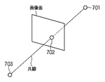
本実施形態では撮像部210におけるレンズ歪みは存在しないか、もしくは補正されているものと仮定し、撮像部210はピンホールカメラであると想定している。式(1)は図7に示すように、空間中の点701と、この点701の画像上の投影点702と、撮像部210(カメラ)位置(視点)703と、は同一直線(共線)上に存在することを示しており、共線条件式とも呼ばれる。図7は、共線条件式を説明する図である。
In the present embodiment, it is assumed that the lens distortion in the
基準座標系における撮像部210の位置を
The position of the
![]()
![]()
、撮像部210の姿勢(実際には、カメラ座標系に対する基準座標系の姿勢)を , The orientation of the imaging unit 210 (actually, the orientation of the reference coordinate system with respect to the camera coordinate system)
![]()
![]()
であるとする。 Suppose that
![]()
![]()
は3自由度の姿勢表現方法であり、姿勢を回転軸ベクトル及び回転角で表現している。回転角をraとすると、raは Is a posture expression method with three degrees of freedom, and the posture is expressed by a rotation axis vector and a rotation angle. When the rotation angle and r a, r a is
![]()
![]()
によって下記の式(2)のように表される。 Is represented by the following formula (2).
また、回転軸ベクトルを Also, the rotation axis vector
![]()
![]()
とすると、 Then,
![]()
![]()
と When
![]()
![]()
の関係は式(3)のように表される。 The relationship is expressed as shown in Equation (3).
![]()
![]()
(回転角ra、回転軸ベクトル (Rotation angle r a , rotation axis vector
![]()
![]()
)と3×3回転変換行列 ) And 3 × 3 rotation transformation matrix
![]()
![]()
との関係は下記の式(4)のように表される。 Is expressed as the following equation (4).
基準座標系上の点 A point on the reference coordinate system
![]()
![]()
のカメラ座標 Camera coordinates
![]()
![]()
は Is
![]()
![]()
、及び ,as well as
![]()
![]()
によって下記の式(5)のように表される。 Is expressed by the following equation (5).
式(1)、(5)から、透視投影変換によって、基準座標上の点 From equations (1) and (5), a point on the reference coordinates is obtained by perspective projection transformation.
![]()
![]()
は下記の式(6)のように画像上の点 Is a point on the image as shown in equation (6) below
![]()
![]()
に投影される。 Projected on.
理想的には、 Ideally
![]()
![]()
、 ,
![]()
![]()
、 ,
![]()
![]()
をもとに式(6)から計算される投影位置(計算位置)と実際に画像上で観察される位置(観察位置)は一致する。そのため、計算位置と観察位置の画像の水平方向のずれをF、垂直方向のずれをG、観察位置を The projection position (calculation position) calculated from the equation (6) based on the above is coincident with the position actually observed on the image (observation position). Therefore, the horizontal deviation between the calculated position and the observation position is F, the vertical deviation is G, and the observation position is
![]()
![]()
とすると、下記の式(7)に示すようにF、Gは0となる。 Then, F and G are 0 as shown in the following formula (7).
F、Gは撮像部210位置
F and G are the positions of the
![]()
![]()
、撮像部210姿勢
,
![]()
![]()
、観察対象点の基準座標上での位置 , The position of the observation point on the reference coordinates
![]()
![]()
に関する関数である。正方形指標は、基準座標系における位置 Is a function related to The square index is the position in the reference coordinate system
![]()
![]()
及び基準座標系に対する姿勢 And attitude to the reference coordinate system
( (
![]()
![]()
に対応した3×3回転変換行列を 3 × 3 rotation transformation matrix corresponding to
![]()
![]()
とする)及び基準座標系におけるスケール And the scale in the reference coordinate system
![]()
![]()
(スケールは、図4に示す指標の中心を基準とした大きさであるため、指標サイズは指標スケールの2倍となる)で表現される。正方形指標の頂点の正方形指標座標系における位置を (Since the scale is based on the center of the index shown in FIG. 4, the index size is twice the index scale). The position of the vertex of the square index in the square index coordinate system
とする。正方形指標の頂点の基準座標系における位置 And The position of the vertex of the square index in the reference coordinate system
![]()
![]()
は下記の式(8)のように、 Is the following equation (8):
![]()
![]()
と When
![]()
![]()
と When
![]()
![]()
に関する関数となる。 Function.
そのため、下記の式(9)に示すように、F、Gは、撮像部210位置
Therefore, as shown in the following equation (9), F and G are the positions of the
![]()
![]()
、撮像部210姿勢
,
![]()
![]()
、正方形指標の位置 , Square indicator position
![]()
![]()
及び正方形指標の姿勢 And the attitude of square indicators
![]()
![]()
及び正方形指標のスケール And square indicator scale
![]()
![]()
の関数となる。 Is a function of
式(9)は撮像部210の位置及び姿勢、指標の位置及び姿勢及びスケールについて非線形な方程式となっている。そこで、1次の項までのテイラー展開を用いて撮像部210の位置及び姿勢、指標の位置及び姿勢及びスケールの近似値の近傍で線形化し、繰返し計算によって撮像部210の位置及び姿勢、指標の位置及び姿勢及びスケールを求める。
Expression (9) is a nonlinear equation regarding the position and orientation of the
式(10)は、それぞれ式(9)を線形化したものである。Δtx、Δty、Δtzは撮像部210の位置、Δωx、Δωy、Δωzは撮像部210の姿勢である。また、Δtsx、Δtsy、Δtszは正方形指標の位置、Δωsx、Δωsy、Δωszは正方形指標の姿勢、ΔLは正方形指標のスケールの近似値に対する補正量を表す。
Equation (10) is a linearization of Equation (9). Δtx, Δty, and Δtz are the positions of the
ここで式(10)のF0、G0は定数であり、撮像部210位置及び姿勢、正方形指標の位置及び姿勢及びスケールの近似値から求まる指標の投影位置(計算位置)と観察位置
Here, F 0 and G 0 in Expression (10) are constants, and the projected position (calculated position) and observation position of the index obtained from the
![]()
![]()
との差である。 Is the difference.
式(10)は、ある画像上で観察される正方形指標の一個の頂点についての観測方程式である。実際には複数の画像上で正方形指標の各頂点が観察されるため、式(10)は複数得られる。そこで複数の式(10)を、撮像部210の位置及び姿勢、正方形指標の位置及び姿勢及びスケールの近似値に対する補正値についての連立方程式として解き、近似値を補正することを繰り返す。これにより、撮像部210の位置及び姿勢、正方形指標の位置及び姿勢及びスケールを求める。
Expression (10) is an observation equation for one vertex of a square index observed on a certain image. Actually, since each vertex of the square index is observed on a plurality of images, a plurality of equations (10) are obtained. Therefore, a plurality of equations (10) are solved as simultaneous equations regarding correction values for the approximate values of the position and orientation of the
図8は、指標位置姿勢サイズ算出部235によって正方形指標の位置及び姿勢及びサイズ(指標スケールの2倍)を求める処理のフローチャートである。尚、詳しくは後述するが、指標位置姿勢算出部250が正方形指標の位置及び姿勢を求める場合にも、図8のフローチャートに従った処理とほぼ同じ処理を行う。
FIG. 8 is a flowchart of processing for obtaining the position, posture, and size (twice the index scale) of the square index by the index position / posture
なお、同図のフローチャートに従った処理を行う前段で、指標を含むシーンの撮影及び撮影画像からの指標抽出及び同定処理については完了しているものとする。 Note that, in the previous stage of performing the processing according to the flowchart of the same figure, it is assumed that the shooting of the scene including the index and the index extraction and identification process from the captured image have been completed.
先ずステップS100では、指標位置姿勢サイズ算出部235は、各画像を撮影した撮像部210の位置及び姿勢、正方形指標の位置及び姿勢及びスケールの近似値の設定を行う。
First, in step S100, the index position / orientation
そしてステップS110以降では、ステップS100で設定された近似値を補正するための補正値を求める。 In step S110 and subsequent steps, a correction value for correcting the approximate value set in step S100 is obtained.
ステップS110では、指標位置姿勢サイズ算出部235は、撮像部210の位置及び姿勢、正方形指標の位置及び姿勢及びスケールの近似値から、投影誤差を最小化するような各近似値の補正値を同時に求めるための連立方程式を確定させる処理を行う。
In step S110, the index position / orientation
次にステップS120では、ステップS110で確定させた連立方程式を解く数値計算処理を行い、各近似値に対する補正値を求める。 Next, in step S120, a numerical calculation process for solving the simultaneous equations determined in step S110 is performed to obtain a correction value for each approximate value.
次にステップS130では、ステップS120で求めた補正値を用いて近似値を補正し、新たな近似値とする。 In step S130, the approximate value is corrected using the correction value obtained in step S120 to obtain a new approximate value.
次にステップS140では、ステップS130で補正された撮像部210の位置及び姿勢、正方形指標の位置及び姿勢及びスケールが最適値に収束しているか否かの判定を行う。係る判定の結果、収束していない場合には処理をステップS110に戻し、以降の処理を繰り返す。一方、収束している場合には、同図のフローチャートに従った指標位置姿勢サイズ算出部235による処理は終了する。
Next, in step S140, it is determined whether or not the position and orientation of the
次に、図8に示した各ステップにおける処理について、より詳細に説明する。 Next, the process in each step shown in FIG. 8 will be described in more detail.
先ず、ステップS100について説明する。 First, step S100 will be described.
ステップS100において、各画像を撮影した撮像部210の位置及び姿勢、正方形指標の位置及び姿勢及びスケールの近似値を設定する。ここで、撮影された画像の枚数をN枚とし、それぞれの画像を撮影した撮像部210の位置を
In step S100, the approximate values of the position and orientation of the
![]()
![]()
、姿勢を , Posture
![]()
![]()
とする。 And
また、位置及び姿勢及びスケールを求める正方形指標の数をKs1個とし、正方形指標の位置を In addition, the number of square indices for obtaining the position, orientation and scale is K s1 , and the positions of the square indices are
![]()
![]()
とし、姿勢を And the posture
![]()
![]()
とし、スケールをLi(i=1,・・・, Ks1)とする。 And the scale is Li (i = 1,..., K s1 ).
撮像部210の位置及び姿勢の近似値は、撮像部210に磁気センサのような6自由度位置姿勢センサを装着し、このセンサの出力値から得てもよいし、基準座標系における位置が既知の点と、この点の画像上での投影位置の対応関係から求めてもよい。また、モーションコントロールカメラのように機械的に撮像部210の位置姿勢を係る近似値として得てもよいし、予め位置姿勢がキャリブレーション済みの撮像部210を用いて撮影し、そのキャリブレーション結果を係る近似値として用いてもよい。即ち、撮像部210の位置及び姿勢の近似値の取得、及び設定については特定の手法に限定するものではない。
The approximate value of the position and orientation of the
一方、指標の位置及び姿勢及びスケールの近似値は、磁気センサのような6自由度位置姿勢センサを装着した撮像部210を用いて複数の位置から撮影し、それら複数枚の画像を元にステレオ計測を行い、概略的に求めた値を用いてもよい。またモーションコントロールカメラのように機械的に位置姿勢を測定可能な撮像部210や、予め位置姿勢がキャリブレーション済みの撮像部210を用いて複数の位置から撮影し、それら複数枚の画像を元にステレオ計測を行い、概略に求めた値を用いてもよい。また、本実施形態の方法等で一度推定された値を用いてもよい。
On the other hand, approximate values of the index position, orientation, and scale are taken from a plurality of positions using an
このように、何れの近似値についても、その取得形態については特に限定するものではない。 As described above, the acquisition form of any approximate value is not particularly limited.
なお、ステップS100では、シーン中に貼られたサイズが既知の指標を1つ以上撮影し、基準座標系における指標スケールの基準になるようにしておく。こうすることで、ステップS110〜ステップS140で求める指標スケールと、基準座標系のスケールとの関係(即ち、ステップS110〜ステップS140で求める指標スケールと、シーン中に存在する指標のサイズとの関係)を対応付けることができる。 In step S100, one or more indices with a known size pasted in the scene are photographed so as to serve as a reference for the index scale in the reference coordinate system. By doing so, the relationship between the index scale obtained in steps S110 to S140 and the scale of the reference coordinate system (that is, the relationship between the index scale obtained in steps S110 to S140 and the size of the index existing in the scene). Can be associated.
次にステップS110では、画像上で観察される指標の数だけ式(10)の観測方程式を確立する。式(10)は、一台の撮像部210の位置及び姿勢の補正値と、一個の正方形指標の位置及び姿勢及びスケールの補正値を未知パラメータとして含む観測方程式である。ここでは、下記の式(11)に示すように、N台のカメラの位置及び姿勢、Ks1個の正方形指標の位置及び姿勢及びスケールについての観測方程式を確立する。この場合、未知数となる補正値の数は、(6×N+7×Ks1)個である。
Next, in step S110, the observation equation of Expression (10) is established for the number of indices observed on the image. Expression (10) is an observation equation that includes the correction values of the position and orientation of one
画像i(i=1,・・・,N)から検出される正方形指標の数をdsi個とすると、N枚の画像から検出される正方形指標の数Dsは、下記の式(12)のようになる。 When the number of square indices detected from the image i (i = 1,..., N) is d si , the number D s of square indices detected from the N images is expressed by the following equation (12). become that way.
N枚の画像から検出される正方形指標の数がDs個である場合、観測方程式(11)が(4×Ds)組、つまり(2×4×Ds)本の観測方程式が立つ。式(11)の観測方程式の左辺の定数項F0、G0を右辺に移項し、連立方程式を立てると、この連立方程式は下記の式(13)に示す如く、行列形式で書くことができる。 When the number of square indexes detected from N images is D s , (4 × D s ) observation equations (11), that is, (2 × 4 × D s ) observation equations are established. When the constant terms F 0 and G 0 on the left side of the observation equation of Equation (11) are transferred to the right side and a simultaneous equation is established, this simultaneous equation can be written in matrix form as shown in Equation (13) below. .
![]()
![]()
はヤコビ行列と呼ばれ、F、Gの撮像部210位置及び姿勢、正方形指標の位置及び姿勢及びスケールについての偏微分係数を並べたものである。ヤコビ行列
Is called a Jacobian matrix, and is an array of partial differential coefficients for the positions and orientations of the F and
![]()
![]()
の行数は、観測方程式の数(2×4×Ds)個であり、列数は未知数の数(6×N+7×Ks1)個である。 Is the number of observation equations (2 × 4 × D s ), and the number of columns is the number of unknowns (6 × N + 7 × K s1 ).
![]()
![]()
は補正値ベクトルである。補正値ベクトルの要素数は未知数の数(6×N+7×Ks1)個である。 Is a correction value vector. The number of elements of the correction value vector is the number of unknowns (6 × N + 7 × K s1 ).
![]()
![]()
は誤差ベクトルであり、近似値による投影位置の計算位置と観察位置 Is an error vector, the calculated position of the projection position by the approximate value and the observation position
![]()
![]()
の差−F0、−G0を要素として持つ。 Difference -F0, -G0 as elements.
![]()
![]()
の要素数は、観測方程式の数(2×4×Ds)個である。 Is the number of observation equations (2 × 4 × D s ).
なお、基準座標系における位置が既知である点指標、又は位置及び姿勢及びスケールが既知の正方形指標を同時に撮影することによって、基準座標系の原点、スケール、姿勢を明示的に指定することができる。これらの指標についての式(11)の方程式では、指標の位置及び姿勢及びスケールについての偏微分係数の値はすべて0となる。基準座標系の原点、スケール、姿勢を明示的に指定するためには、点指標であれば位置が既知の同一直線状にない点指標を3個用いればよく、正方形指標であれば位置及び姿勢及びスケールが既知の正方形指標を1個用いればよい。 Note that the origin, scale, and orientation of the reference coordinate system can be explicitly specified by simultaneously capturing a point index with a known position in the reference coordinate system or a square index with a known position, orientation, and scale. . In the equation (11) for these indices, the values of partial differential coefficients for the position and orientation of the index and the scale are all zero. In order to explicitly specify the origin, scale, and orientation of the reference coordinate system, it is sufficient to use three point indicators that are not in the same straight line with known positions if they are point indicators, and if they are square indicators, the position and orientation And one square index with a known scale may be used.
次に、ステップS120では、撮像部210の位置及び姿勢、正方形指標の位置及び姿勢及びスケールの近似値に対する補正値を求める。補正値は上記式(13)に基づいて求める。ヤコビ行列
Next, in step S120, correction values for the approximate values of the position and orientation of the
![]()
![]()
が正方行列である場合には、式(13)の両辺に Is a square matrix, both sides of equation (13)
![]()
![]()
の逆行列をかけることで補正値ベクトル The correction value vector by multiplying the inverse matrix of
![]()
![]()
を求める。 Ask for.
![]()
![]()
が正方行列でない場合には、下記の式(14)に示すように最小二乗法によって補正値ベクトル Is not a square matrix, the correction value vector is obtained by the least square method as shown in the following equation (14).
![]()
![]()
を求める。 Ask for.
ここで、ヤコビ行列 Where Jacobian matrix
![]()
![]()
の各要素の求め方について説明する。 How to find each element of will be described.
まず First
![]()
![]()
とおく。上記式(6)、(7)よりF、Gは下記の式(15)のように書ける。F、Gはxc、yc、zcの関数となる。 far. From the above equations (6) and (7), F and G can be written as the following equation (15). F and G are functions of x c , y c and z c .
F、Gのxc、yc、zcによる偏微分係数を各要素に持つヤコビ行列 Jacobian matrix with partial differential coefficients of F and G by x c , y c and z c
は、下記の式(16)のように書ける。 Can be written as the following equation (16).
ここで、xc、yc、zcが変数s1、s2、・・・、smの関数であるならば、F、Gもまたs1、s2、・・・、smの関数である。F、Gのs1、s2、・・・、smによる偏微分係数を各要素に持つヤコビ行列 Here, if x c , y c and z c are functions of variables s1, s2,..., Sm, F and G are also functions of s1, s2,. Jacobian matrix with F, G s1, s2,.
は、下記の式(17)のように分解することができる。 Can be decomposed as shown in the following equation (17).
![]()
![]()
をそれぞれカメラ位置、カメラ姿勢、指標位置、指標姿勢、指標スケールに置き換えて With camera position, camera posture, index position, index posture, index scale respectively
を求めることにより、F、Gのカメラ位置、カメラ姿勢、指標位置、指標姿勢、指標スケールについての偏微分係数を求めることができる。 Can be used to obtain partial differential coefficients for F and G camera positions, camera orientations, index positions, index orientations, and index scales.
F、Gのカメラ位置tx、ty、tzによる偏微分係数を各要素に持つヤコビ行列 Jacobian matrix with partial derivatives of F, G camera positions t x , t y , t z as elements
は、式(5)より、下記の式(18)のように書ける。 Can be written from the equation (5) as the following equation (18).
ただし、姿勢 However, posture
![]()
![]()
と3×3回転変換行列 And 3 × 3 rotation transformation matrix
![]()
![]()
の関係は式(4)で表される。 The relationship is expressed by equation (4).
F、Gのカメラ姿勢ωx、ωy、ωzによる偏微分係数を各要素に持つヤコビ行列 Jacobian matrix with partial differential coefficients for F and G camera orientations ωx, ωy, and ωz in each element
は、下記の式(19)のように分解して書ける。 Can be decomposed and written as in the following equation (19).
ここで、 here,
は下記の式(20)に示すようなヤコビ行列である。 Is a Jacobian matrix as shown in the following equation (20).
また、 Also,
は下記の式(21)に示すようなヤコビ行列である。 Is a Jacobian matrix as shown in the following equation (21).
また、 Also,
として、 As
は下記の式(22)に示すようなヤコビ行列である。 Is a Jacobian matrix as shown in the following equation (22).
さらに、 further,
は下記の式(23)に示すようなヤコビ行列である。 Is a Jacobian matrix as shown in the following equation (23).
F、Gの正方形指標の位置tsx、tsy、tszによる偏微分係数を各要素に持つヤコビ行列 Jacobian matrix with partial differential coefficients in each element based on positions tsx, tsy, and tsz of square indices of F and G
は、式(5)、式(8)より、下記の式(24)のように書ける。 Can be written as the following equation (24) from the equations (5) and (8).
F、Gの正方形指標の姿勢 F, G square indicator posture
![]()
![]()
による偏微分係数を各要素に持つヤコビ行列 Jacobian matrix with partial differential coefficients by
は、下記の式(25)のように分解することができる。 Can be decomposed as shown in the following equation (25).
は、式(21)〜(23)と同様にして求めることができる。 Can be obtained in the same manner as equations (21) to (23).
F、Gの正方形指標のスケールLによる偏微分係数を各要素に持つヤコビ行列 Jacobian matrix with partial differential coefficients of each element based on scale L of square indices of F and G
は、下記の式(26)のように分解することができる。 Can be decomposed as shown in the following equation (26).
そしてこのようにして求めた補正値を用いて、ステップS130では、近似値の更新を行う。 In step S130, the approximate value is updated using the correction value thus obtained.
次にステップS140では、上述の収束判定を行う。収束判定は、補正値の絶対値が指定した閾値を下回る、投影位置の計算位置と観察位置の差が指定した閾値を下回るなどの条件を判定することにより行う。この例の場合、「下回った」場合には、「収束した」と判定する。 Next, in step S140, the above-described convergence determination is performed. The convergence determination is performed by determining a condition such that the absolute value of the correction value falls below a specified threshold value, or the difference between the calculation position of the projection position and the observation position falls below a specified threshold value. In this example, when “below”, it is determined that “convergence” has occurred.
係る収束判定処理の結果、収束していると判定された場合、指標の位置及び姿勢及びスケール推定を終了し、指標のスケールの値を2倍にした指標サイズを出力する。収束していない場合は、処理をステップS110に戻し、補正された撮像部210の位置及び姿勢、正方形指標の位置及び姿勢及びスケールの近似値をを用いて再度、再度連立方程式を確立し、補正値を求める処理を繰り返し行う。
As a result of the convergence determination process, when it is determined that the image has converged, the position and orientation of the index and the scale estimation are terminated, and an index size obtained by doubling the index scale value is output. If not converged, the process returns to step S110, and the simultaneous equations are established again using the corrected position and orientation of the
<4. 指標配置条件設定>
指標配置条件設定部240は、指標の配置に関する拘束条件を設定する。本実施形態では、指標の配置に関する拘束条件として、最終的に指標の位置及び姿勢を求める際の指標のサイズを、実際にユーザが作成した指標のサイズと同じにするという拘束条件を与える。
<4. Index placement condition setting>
The index placement
上記ステップS100〜ステップS140で求めた正方形指標のサイズ(スケールの2倍)は、あくまで計算上求めたサイズであり、実際にユーザが作成した指標のサイズとは一致せずに誤差が生じている場合がある。そこで、ステップS100〜ステップS140で求めた少なくとも1つ以上の正方形指標のサイズの各々を、実際にユーザが作成した指標のサイズに修正する。 The size of the square index obtained in Steps S100 to S140 (twice the scale) is a size obtained by calculation to the last, and does not match the size of the index actually created by the user, resulting in an error. There is a case. Therefore, each of the sizes of at least one square index obtained in steps S100 to S140 is corrected to the size of the index actually created by the user.
実際にユーザが作成した指標のサイズとしては、以下の2つのケースが考えられる。 The following two cases can be considered as the size of the index actually created by the user.
・ (ケース1) 本実施形態の方法を実行する前に、プリンタ312を利用して指標を印刷する。この印刷することになっている指標のサイズは予め定められた幾つかのサイズのうち、ユーザが指示したものであるとする。
(Case 1) Before executing the method of the present embodiment, the index is printed using the
例えば、予め幾つかの指標サイズを決めておき、決めた幾つかのサイズを登録したテーブルを作成する。そして作成したテーブルのデータをハードディスク305に登録しておく。図5(a)は、複数種の指標サイズが登録されているテーブルの構成例を示す図である。
For example, several index sizes are determined in advance, and a table in which the determined several sizes are registered is created. The created table data is registered in the
同図に示す如く、テーブルには、10mm毎に指標サイズが登録されている。即ち、ここで用いられる指標のサイズとは、既定の離散値(10mm刻み)のうち何れかである。そしてユーザは、係るテーブルに登録されている何れか1つのサイズを選択する。選択方法については、例えば、本コンピュータ300に不図示の表示装置を接続し、この表示装置の表示画面上にこのテーブルに登録されている全てのサイズを表示し、何れか1つをマウス308やキーボード309を用いて指示するようにする。即ち、選択方法は特に限定するものではない。そして選択したサイズの指標をプリンタ312にて印刷する。
As shown in the figure, an index size is registered in the table every 10 mm. In other words, the size of the index used here is one of predetermined discrete values (10 mm increments). Then, the user selects any one size registered in the table. As for the selection method, for example, a display device (not shown) is connected to the
・ (ケース2) ケース1と同様、本実施形態の方法を実行する前に、プリンタ312を利用して指標を印刷する。ただ、ケース1と異なる点は、予め各指標のサイズは定められておらず、ユーザが任意の大きさを指定して印刷したサイズを、ハードディスク305等に新たなテーブル値として保存する。
(Case 2) Similar to
図5(b)は、ユーザが指定した任意のサイズが登録されているテーブルの構成例を示す図である。同図に示す如く、ユーザが実際に印刷した23mm、12mm、45mm、73mmといった(任意の)大きさの指標サイズがテーブルに登録されている。 FIG. 5B is a diagram illustrating a configuration example of a table in which an arbitrary size designated by the user is registered. As shown in the figure, index sizes of (arbitrary) sizes such as 23 mm, 12 mm, 45 mm, and 73 mm actually printed by the user are registered in the table.
指標配置条件設定部240は、ステップS100〜ステップS140で求めた1つ以上の正方形指標のサイズ(スケールの2倍)の各々を元に、図5(a)、若しくは図5(b)に示すテーブルに登録されているサイズのうち最も近いサイズに修正する。
The index arrangement
例えば、ステップS100〜ステップS140で求めた正方形指標の一辺のサイズが32mmである場合、図5(a)の例では、最も近いサイズである30mmに修正する。また、図5(b)の例では、最も近いサイズである23mmに修正する。 For example, when the size of one side of the square index obtained in steps S100 to S140 is 32 mm, in the example of FIG. 5A, it is corrected to the closest size of 30 mm. Moreover, in the example of FIG.5 (b), it corrects to 23 mm which is the nearest size.
<5. 指標の位置姿勢算出
指標位置姿勢算出部250は、シーン中に存在する1つ以上の指標各々の位置及び姿勢を求める。このとき、本実施形態では、指標配置条件設定部240でサイズを修正した後の正方形指標のスケールを利用する。即ち、上記説明において図5(a)のテーブルを用いた場合には、ステップS100〜S140で求めた正方形指標のサイズ32mmではなく、図5(a)のテーブル中の最も近いサイズである30mmを「修正した指標スケール」として利用する。また、図5(b)のテーブルを用いた場合には、図5(b)のテーブル中の最も近いサイズである23mmを「修正した指標スケール」として利用する。
<5. Index Position / Orientation Calculation The index position /
指標位置姿勢算出部250は、シーン中に存在する指標の位置及び姿勢を求めるのであるが、基本的には指標位置姿勢サイズ算出部235で指標の位置及び姿勢及びサイズを求める方法(式(1)〜(26)を用いた方法)とほぼ同じ方法によって行う。唯一異なる点は、指標配置条件設定部240で修正した指標のサイズを元に換算した指標スケールを定数として、撮像部210の位置姿勢と指標の位置及び姿勢を求めるようにすることである。
The index position /
以上の説明により、本実施形態によれば、指標が配置されたシーンの画像を多数撮影し、撮影された画像から指標を検出・同定し、先ず、指標の位置及び姿勢及びサイズを求める。そして、求めた指標のサイズを、ユーザがプリンタで指標を印刷する際に実際に指定した指標のサイズに修正し、修正したサイズを用いて指標の位置及び姿勢を求め直す。 As described above, according to the present embodiment, a large number of scene images in which indices are arranged are photographed, and indices are detected and identified from the captured images. First, the position, orientation, and size of the indices are obtained. Then, the obtained index size is corrected to the index size actually designated when the user prints the index with the printer, and the position and orientation of the index are obtained again using the corrected size.
このようにすることで、画像を利用して指標のサイズを求めることができる。また、実際にユーザが作成する指標のサイズを、最終的に指標の位置及び姿勢を求める際の指標のサイズにすることにより、指標の位置及び姿勢を、より高精度に求めることが可能となる。 By doing so, the size of the index can be obtained using the image. In addition, by making the size of the index actually created by the user the size of the index when the position and orientation of the index are finally obtained, the position and orientation of the index can be obtained with higher accuracy. .
[第2の実施形態]
第1の実施形態では、指標が配置されたシーンの画像を多数撮影し、撮影された画像から指標を検出・同定し、まず指標の位置及び姿勢及びサイズを求めた。そして、求めた指標のサイズを、ユーザがプリンタで指標を印刷する際に実際に指定した指標のサイズに修正し、修正したサイズを用いて指標の位置及び姿勢を求め直した。
[Second Embodiment]
In the first embodiment, a large number of images of a scene where an index is arranged are captured, the index is detected and identified from the captured image, and the position, orientation, and size of the index are first obtained. Then, the size of the obtained index is corrected to the size of the index actually designated when the user prints the index with the printer, and the position and orientation of the index are obtained again using the corrected size.
本実施形態では、指標が配置されたシーンの画像を多数撮影し、撮影された画像から指標を検出・同定し、まず指標の位置及び姿勢及びサイズを求めるところまでは第1の実施形態と同じであり、以降の処理が異なる。本実施形態では次に、求めた指標の位置を、ユーザが実際に指標を配置した位置に修正し、修正した位置を用いて指標の姿勢及びサイズを求めなおす。ここで、「ユーザが実際に指標を配置した位置」とは、例えば指標の配置対象としてグリッドが付されている現実の机を想定し、「机のグリッドに合わせてユーザが指標を配置する場合の位置」である。 In this embodiment, a large number of images of a scene in which an index is arranged are captured, the index is detected and identified from the captured image, and first the position, orientation, and size of the index are obtained, and then the same as in the first embodiment. The subsequent processing is different. Next, in the present embodiment, the position of the obtained index is corrected to the position where the user has actually placed the index, and the attitude and size of the index are obtained again using the corrected position. Here, “the position where the user has actually placed the index” is assumed to be, for example, a real desk with a grid as an index placement target, and “when the user places the index according to the desk grid. Position.
図9は、本実施形態に係るシステムの機能構成を示すブロック図である。なお、同図において図2と同じ部分については同じ番号を付けており、その説明は省略する。 FIG. 9 is a block diagram showing a functional configuration of the system according to the present embodiment. In the figure, the same parts as those in FIG.
同図に示す如く、本実施形態に係るシステムは、撮像部210と、指標姿勢サイズ推定装置900とで構成されている。指標姿勢サイズ推定装置900は、画像取り込み部220、指標検出同定部230、指標位置姿勢サイズ算出部235、指標配置条件設定部241、指標姿勢サイズ算出部251により構成されている。
As shown in the figure, the system according to this embodiment includes an
なお、図3に示したコンピュータ300は、指標姿勢サイズ推定装置900についても同様に適用することができる。その場合には、指標配置条件設定部241、指標姿勢サイズ算出部251の機能をCPU301に実行させるためのプログラムやデータをハードディスク305に保存しておく。そしてこのプログラムやデータをRAM307にロードし、CPU301がこのロードされたプログラムやデータを用いて処理を実行すれば、CPU301は、指標姿勢サイズ推定装置900が行うものとして後述する各処理を実行することになる。
Note that the
以下では、図9における指標配置条件設定部241、指標姿勢サイズ算出部251についての説明を行う。 Hereinafter, the index arrangement condition setting unit 241 and the index posture size calculation unit 251 in FIG. 9 will be described.
<4. 指標配置条件設定>
指標配置条件設定部241は、指標の配置に関する拘束条件を設定する。本実施形態では、指標の配置に関する拘束条件として、最終的に指標の姿勢及びサイズを求める際の指標の位置を、ユーザが実際に指標を配置した位置と同じにするという拘束条件を与える。
<4. Index placement condition setting>
The index arrangement condition setting unit 241 sets a constraint condition regarding the arrangement of the index. In the present embodiment, as a constraint condition regarding the placement of the index, a constraint condition that the position of the index when the posture and size of the index are finally obtained is the same as the position where the user actually placed the index is given.
指標位置姿勢サイズ算出部235が求めた正方形指標の位置(換言すれば、上記ステップS100〜S140で求めた正方形指標の位置)は、あくまで計算上求めた位置であり、ユーザが実際に指標を配置した位置とは一致せずに誤差が生じている場合がある。そこで、ステップS100〜S140で求めた1つ以上の正方形指標の位置の各々を、ユーザが実際に指標を配置した位置に修正する。 The position of the square index obtained by the index position / posture size calculation unit 235 (in other words, the position of the square index obtained in steps S100 to S140) is a calculated position to the last, and the user actually places the index. There is a case where an error occurs without matching with the position. Therefore, each of the positions of the one or more square indices obtained in steps S100 to S140 is corrected to the position where the user has actually placed the indices.
指標配置条件設定部241は、ステップS100〜S140で求めた1つ以上の正方形指標の位置の各々を、図10に示す現実の机上のグリッドのうちの最も近い位置に修正する。例えば、図10に示す現実の机の上には50mm刻みに離散的なグリッドが書かれているとする。 The index arrangement condition setting unit 241 corrects each of the positions of the one or more square indices obtained in steps S100 to S140 to the closest position on the actual desk grid shown in FIG. For example, it is assumed that a discrete grid is written in 50 mm increments on the actual desk shown in FIG.
図10は、現実物体としての机の上に設けられたグリッドについて説明する図である。そして、ステップS100〜S140で求めた正方形指標の位置が、机座標の原点を基準として(X,Y)=(141mm、203mm)である場合、最も近いグリッド位置である(X,Y)=(150mm、200mm)に修正する。なお、机座標は、机の法線方向をZ軸とし、X軸、Y軸を机の二つの辺に平行になるようにとっている。そして各グリッド位置に関する情報は予め作成され、ハードディスク305に登録されているものとする。
FIG. 10 is a diagram illustrating a grid provided on a desk as a real object. If the position of the square index obtained in steps S100 to S140 is (X, Y) = (141 mm, 203 mm) with the origin of desk coordinates as a reference, it is the closest grid position (X, Y) = ( 150mm, 200mm). The desk coordinates are such that the normal direction of the desk is the Z axis, and the X and Y axes are parallel to the two sides of the desk. Information about each grid position is created in advance and registered in the
<5. 指標の姿勢サイズ算出>
指標姿勢サイズ算出部251は、シーン中に存在する1つ以上の指標各々の姿勢及びサイズを求める。このとき、本実施形態においては、指標配置条件設定部241で修正した後の正方形指標の位置を利用する。すなわち上記説明においては、ステップS100〜S140で求めた正方形指標の位置(X,Y)=(141mm、203mm)ではなく、図10の机上のグリッドで最も近い位置である(X,Y)=(150mm、200mm)を、修正した位置として利用する。
<5. Index posture size calculation>
The index posture size calculation unit 251 obtains the posture and size of each of one or more indexes existing in the scene. At this time, in the present embodiment, the position of the square marker after being corrected by the marker arrangement condition setting unit 241 is used. In other words, in the above description, the position (X, Y) = (141 mm, 203 mm) of the square index obtained in steps S100 to S140 is not the position (X, Y) = (X, Y) = ( 150 mm, 200 mm) is used as the corrected position.
指標姿勢サイズ算出部251は、シーン中に存在する指標の姿勢及びサイズを求めるのであるが、基本的には指標位置姿勢サイズ算出部235で指標の位置及び姿勢及びサイズを求める方法(式(1)〜(26)を用いた方法)とほぼ同じ方法によって行う。唯一異なる点は、指標配置条件設定部241で修正した指標の位置を定数として、撮像部210の位置姿勢と指標の姿勢及びサイズを求めるようにすることである。
The index posture size calculation unit 251 calculates the posture and size of an index existing in the scene. Basically, the index position / posture
以上の説明により、本実施形態によれば、指標が配置されたシーンの画像を多数撮影し、撮影された画像から指標を検出・同定し、まず指標の位置及び姿勢及びサイズを求める。そして、求めた指標の位置を、ユーザが実際に指標を配置した位置に修正し、修正した位置を用いて指標の姿勢及びサイズを求め直す。 As described above, according to the present embodiment, a large number of scene images in which indices are arranged are photographed, indices are detected and identified from the captured images, and the position, orientation, and size of the indices are first obtained. Then, the obtained index position is corrected to the position where the user actually arranged the index, and the index posture and size are obtained again using the corrected position.
このようにすることで、画像を利用して指標のサイズを求めることができる。また、ユーザが実際に指標を配置した位置を、最終的に指標の姿勢及びサイズを求める際の指標の位置にすることにより、指標の姿勢及びサイズを、より高精度に求めることが可能となる。 By doing so, the size of the index can be obtained using the image. In addition, by setting the position where the index is actually placed by the user as the position of the index when the attitude and size of the index are finally obtained, the attitude and size of the index can be obtained with higher accuracy. .
[第3の実施形態]
第1の実施形態では、指標が配置されたシーンの画像を多数撮影し、撮影された画像から指標を検出・同定し、まず指標の位置及び姿勢及びサイズを求めた。そして、求めた指標のサイズを、ユーザがプリンタで指標を印刷する際に実際に指定した指標のサイズに修正し、修正したサイズを用いて指標の位置及び姿勢を求め直した。
[Third Embodiment]
In the first embodiment, a large number of images of a scene where an index is arranged are captured, the index is detected and identified from the captured image, and the position, orientation, and size of the index are first obtained. Then, the size of the obtained index is corrected to the size of the index actually designated when the user prints the index with the printer, and the position and orientation of the index are obtained again using the corrected size.
本実施形態では、指標が配置されたシーンの画像を多数撮影し、撮影された画像から指標を検出・同定し、まず指標の位置及び姿勢及びサイズを求めるところまでは第1の実施形態と同じであり、以降の処理が異なる。本実施形態では次に、求めた指標の姿勢を、ユーザが実際に指標を配置した姿勢に修正し、修正した姿勢を用いて指標の位置及びサイズを求めなおす。ここで、「ユーザが実際に指標を配置した姿勢」とは、例えば指標の配置対象として現実の床や壁や天井を想定し、「床や壁や天井に対してユーザが指標を配置する場合の姿勢」である。 In this embodiment, a large number of images of a scene in which an index is arranged are captured, the index is detected and identified from the captured image, and first the position, orientation, and size of the index are obtained, and then the same as in the first embodiment. The subsequent processing is different. Next, in the present embodiment, the posture of the obtained index is corrected to the posture in which the user has actually placed the index, and the position and size of the index are obtained again using the corrected posture. Here, “the posture in which the user has actually placed the index” means, for example, an actual floor, wall, or ceiling as the placement target of the index, and “attitude when the user places the indicator on the floor, wall, or ceiling” Is.
図11は、本実施形態に係るシステムの機能構成を示すブロック図である。なお、同図において図2と同じ部分については同じ番号を付けており、その説明は省略する。 FIG. 11 is a block diagram showing a functional configuration of the system according to the present embodiment. In the figure, the same parts as those in FIG.
同図に示す如く、本実施形態に係るシステムは、撮像部210と、指標位置サイズ推定装置1100とで構成されている。指標位置サイズ推定装置1100は、画像取り込み部220、指標検出同定部230、指標位置姿勢サイズ算出部235、指標配置条件設定部242、指標位置サイズ算出部252により構成されている。
As shown in the figure, the system according to this embodiment includes an
なお、図3に示したコンピュータ300は、指標姿勢サイズ推定装置1100についても同様に適用することができる。その場合には、指標配置条件設定部242、指標位置サイズ算出部252の機能をCPU301に実行させるためのプログラムやデータをハードディスク305に保存しておく。そしてこのプログラムやデータをRAM307にロードし、CPU301がこのロードされたプログラムやデータを用いて処理を実行すれば、CPU301は、指標位置サイズ推定装置1100が行うものとして後述する各処理を実行することになる。
Note that the
以下では、図11における指標配置条件設定部242、指標位置サイズ算出部252についての説明を行う。
Hereinafter, the index arrangement
<4. 指標配置条件設定>
指標配置条件設定部242は、指標の配置に関する拘束条件を設定する。本実施形態では、指標の配置に関する拘束条件として、最終的に指標の位置及びサイズを求める際の指標の姿勢を、ユーザが実際に指標を配置した姿勢と同じにするという拘束条件を与える。
<4. Index placement condition setting>
The index arrangement
指標位置姿勢サイズ算出部235が求めた正方形指標の姿勢(換言すれば、上記ステップS100〜S140で求めた正方形指標の姿勢)は、あくまで計算上求めた姿勢であり、ユーザが実際に指標を配置した姿勢とは一致せずに誤差が生じている場合がある。そこで、ステップS100〜S140で求めた1つ以上の正方形指標の姿勢の各々を、ユーザが実際に指標を配置した姿勢に修正する。 The posture of the square index obtained by the index position / posture size calculation unit 235 (in other words, the posture of the square index obtained in steps S100 to S140) is a posture obtained by calculation to the last, and the user actually places the indicator. There may be an error that does not match the posture. Therefore, each of the postures of the one or more square markers obtained in steps S100 to S140 is corrected to the posture in which the user has actually placed the markers.
指標配置条件設定部242は、ステップS100〜S140で求めた1つ以上の正方形指標の姿勢の各々を、図12に示す現実の床や壁のうちの最も近い姿勢に修正する。例えば、図12に示す床や壁は、基準座標系の各軸に対して水平もしくは垂直といった離散的な姿勢となっている。そしてステップS100〜S140で求めた正方形指標の姿勢が、基準座標系に対して水平或いは垂直からずれている場合は、基準座標系に対して最も近い水平姿勢或いは垂直姿勢になるように、即ち最も近い床や壁の姿勢と同じになるように修正する。指標のz軸を中心とした回転誤差が生じている場合は、図4に示す指標のx軸、y軸が、基準座標系に対して最も近い水平もしくは垂直方向になるように修正すればよい。図12は、指標を配置する壁や床を示す図である。なお、指標の姿勢を修正するための基準としては、床や壁に加え、天井を用いても良い。
The index arrangement
<5. 指標の位置サイズ算出>
指標位置サイズ算出部252は、シーン中に存在する1つ以上の指標各々の位置及びサイズを求める。このとき、本実施形態においては、指標配置条件設定部242で修正した後の正方形指標の姿勢を利用する。すなわち上記説明においては、ステップS100〜S140で求めた正方形指標の姿勢ではなく、図12の床や壁で最も近い姿勢を、修正した姿勢として利用する。
<5. Calculation of index position size>
The index position
指標位置サイズ算出部252は、シーン中に存在する指標の位置及びサイズを求めるのであるが、基本的には指標位置姿勢サイズ算出部235で指標の位置及び姿勢及びサイズを求める方法(式(1)〜(26)を用いた方法)とほぼ同じ方法によって行う。唯一異なる点は、指標配置条件設定部242で修正した指標の姿勢を定数として、撮像部210の位置姿勢と、指標の位置及びサイズを求めることである。
The index position
以上の説明により、本実施形態によれば、指標が配置されたシーンの画像を多数撮影し、撮影された画像から指標を検出・同定し、まず指標の位置及び姿勢及びサイズを求める。そして、求めた指標の姿勢を、ユーザが実際に指標を配置した姿勢に修正し、修正した姿勢を用いて指標の位置及びサイズを求め直す。 As described above, according to the present embodiment, a large number of scene images in which indices are arranged are photographed, indices are detected and identified from the captured images, and the position, orientation, and size of the indices are first obtained. Then, the posture of the obtained index is corrected to the posture in which the user has actually placed the index, and the position and size of the index are obtained again using the corrected posture.
このようにすることで、画像を利用して指標のサイズを求めることができる。また、ユーザが実際に指標を配置した姿勢を、最終的に指標の位置及びサイズを求める際の指標の姿勢にすることにより、指標の位置及びサイズを、より高精度に求めることが可能となる。 By doing so, the size of the index can be obtained using the image. Further, the position of the index and the size can be obtained with higher accuracy by making the attitude of the index where the user has actually placed the index into the attitude of the index when finally obtaining the position and size of the index. .
<変形例1>
第1乃至3の実施形態では、指標の位置、姿勢、サイズのうち1つのパラメータを固定し、残りの2つのパラメータを求めなおしていた。しかし、指標の位置、姿勢、サイズのうち2つのパラメータを固定し、残りの1つのパラメータを求めなおしてもよいことは言うまでもない。
<
In the first to third embodiments, one parameter of the index position, posture, and size is fixed, and the remaining two parameters are obtained again. However, it goes without saying that two parameters of the index position, orientation, and size may be fixed and the remaining one parameter may be obtained again.
<変形例2>
第1乃至3の実施形態では、指標の位置、姿勢、サイズのうち1つのパラメータを固定する際、ユーザによって物理的に設定したパラメータに最も近いパラメータに修正していた。
<
In the first to third embodiments, when one parameter among the position, posture, and size of the index is fixed, the parameter is corrected to the parameter that is closest to the parameter physically set by the user.
しかし、指標を撮影するシーンの光源環境が劣悪な場合など、特殊なケースにおいては、最も近いパラメータが正しい値とは限らない場合がある。そのようなケースに対処するために、最終的に求めた撮像部210の位置姿勢に仮想空間を観察する視点を設定し、設定した視点から見える仮想空間の画像を生成し、現実空間画像に合成する。そして、適切に合成されていないとユーザが判断した場合は、その旨をマウス308やキーボード309を用いて入力する。この入力がなされた場合には、固定するパラメータの値を、最も近い3個(2以上の整数で表される個数)のパラメータの中から選択可能にし、CGが適切に合成されるまで選択したパラメータを元に計算し直してもよい。
However, in a special case such as when the light source environment of the scene where the index is photographed is poor, the closest parameter may not always be the correct value. In order to deal with such a case, a viewpoint for observing the virtual space is set to the position and orientation of the
<変形例4>
第2の実施形態では、指標の位置をグリッドのうちの最も近い位置に修正していた。しかしその代わりに、推定した指標の位置を元に、複数の指標間の距離が一定であるという拘束条件を導入し、指標の配置情報を、より高精度に求めてもよい。すなわち、複数の指標間の距離が一定であるという拘束条件を用いることで複数の指標位置を定数とし、指標の姿勢及びサイズを求め直してもよい。
<Modification 4>
In the second embodiment, the index position is corrected to the closest position in the grid. However, instead, a constraint condition that the distance between a plurality of indices is constant may be introduced based on the estimated index position, and the index placement information may be obtained with higher accuracy. That is, by using the constraint condition that the distance between the plurality of indices is constant, the plurality of index positions may be set as constants, and the attitude and size of the indices may be obtained again.
<変形例5>
第1乃至3の実施形態では、指標の配置情報の補正方法として、観測方程式をテイラー展開し、その1次の項までを利用して繰り返し補正していく方法を用いた。これは、ある繰り返しの一過程において、局所的に観測方程式を線形近似し、誤差0となると仮定した場合の未知パラメータの補正量を推定する方法であり、一般にニュートン法と呼ばれている方法と等価な方法である。ニュートン法は非線形方程式を数値演算により求解する代表的な方法であるが、上記実施形態に利用する繰り返し演算方法はこの方法に限ったものではない。
<Modification 5>
In the first to third embodiments, as a method for correcting the index arrangement information, a method is used in which the observation equation is Taylor-developed and corrected repeatedly using the first order term. This is a method of linearly approximating the observation equation locally in one iteration and estimating the correction amount of the unknown parameter when it is assumed that the error is zero. It is an equivalent method. The Newton method is a typical method for solving a nonlinear equation by numerical calculation, but the iterative calculation method used in the above embodiment is not limited to this method.
例えば、ニュートン法と同様に周知の技術として知られているLevenberg-Marquardt法のように、一過程において推定される未知パラメータの補正量のばらつきに基づいて、補正量を動的に変更してもよい。また、テイラー展開した結果をより高次の項まで考慮して、繰り返し演算を行うような方法であっても良い。 For example, like the Newton method, the Levenberg-Marquardt method, which is known as a well-known technique, can be used to dynamically change the correction amount based on the variation in the correction amount of the unknown parameter estimated in one process. Good. Further, it may be a method in which the result of Taylor expansion is taken into consideration up to higher order terms and repeated calculation is performed.
即ち、上記各実施形態の本質は、配置情報量の異なる複数種類の指標が混在して存在している場合であっても、それぞれの種類の指標を有効に利用して最適な解を求めることにある。従って、数値解法としての繰り返し演算の具体的な方法によって本質が失われるものではない。 In other words, the essence of each of the embodiments described above is to find an optimal solution by effectively using each type of index even when a plurality of types of indexes having different arrangement information amounts exist. It is in. Therefore, the essence is not lost by a specific method of iterative calculation as a numerical solution.
[その他の実施形態]
また、本発明の目的は、以下のようにすることによって達成されることはいうまでもない。即ち、前述した実施形態の機能を実現するソフトウェアのプログラムコードを記録した記録媒体(または記憶媒体)を、システムあるいは装置に供給する。そして、そのシステムあるいは装置のコンピュータ(またはCPUやMPU)が記録媒体に格納されたプログラムコードを読み出し実行する。この場合、記録媒体から読み出されたプログラムコード自体が前述した実施形態の機能を実現することになり、そのプログラムコードを記録した記録媒体は本発明を構成することになる。
[Other Embodiments]
Needless to say, the object of the present invention can be achieved as follows. That is, a recording medium (or storage medium) that records a program code of software that implements the functions of the above-described embodiments is supplied to a system or apparatus. Then, the computer (or CPU or MPU) of the system or apparatus reads and executes the program code stored in the recording medium. In this case, the program code itself read from the recording medium realizes the functions of the above-described embodiment, and the recording medium on which the program code is recorded constitutes the present invention.
また、コンピュータが読み出したプログラムコードを実行することにより、そのプログラムコードの指示に基づき、コンピュータ上で稼働しているオペレーティングシステム(OS)などが実際の処理の一部または全部を行う。その処理によって前述した実施形態の機能が実現される場合も含まれることは言うまでもない。 Further, by executing the program code read by the computer, an operating system (OS) or the like running on the computer performs part or all of the actual processing based on the instruction of the program code. Needless to say, the process includes the case where the functions of the above-described embodiments are realized.
さらに、記録媒体から読み出されたプログラムコードが、コンピュータに挿入された機能拡張カードやコンピュータに接続された機能拡張ユニットに備わるメモリに書込まれたとする。その後、そのプログラムコードの指示に基づき、その機能拡張カードや機能拡張ユニットに備わるCPUなどが実際の処理の一部または全部を行い、その処理によって前述した実施形態の機能が実現される場合も含まれることは言うまでもない。 Furthermore, it is assumed that the program code read from the recording medium is written in a memory provided in a function expansion card inserted into the computer or a function expansion unit connected to the computer. After that, based on the instruction of the program code, the CPU included in the function expansion card or function expansion unit performs part or all of the actual processing, and the function of the above-described embodiment is realized by the processing. Needless to say.
本発明を上記記録媒体に適用する場合、その記録媒体には、先に説明したフローチャートに対応するプログラムコードが格納されることになる。 When the present invention is applied to the recording medium, program code corresponding to the flowchart described above is stored in the recording medium.
Claims (12)
画像取得手段が、指標が含まれるシーンが撮影された画像を取得する画像取得工程と、
指標検出手段が、前記画像から指標を検出する指標検出工程と、
第1の指標配置情報推定手段が、前記指標検出工程で検出した指標のシーン中における配置情報を推定する第1の指標配置情報推定工程と、
指標情報修正手段が、前記第1の指標配置情報推定工程で推定した配置情報のうち少なくとも1つを既知の値に修正する指標情報修正工程と、
第2の指標配置情報推定手段が、前記指標情報修正工程で修正した配置情報を定数として、前記指標情報修正工程で値を修正していない配置情報を推定する第2の指標配置情報推定工程と
を備えることを特徴とする情報処理方法。 An information processing method for estimating the placement information of an index,
An image acquisition step in which the image acquisition means acquires an image in which a scene including the index is captured;
An index detecting step in which the index detecting means detects the index from the image;
A first index arrangement information estimation unit, wherein the first index arrangement information estimation unit estimates the arrangement information in the scene of the index detected in the index detection process;
An index information correcting step in which the index information correcting means corrects at least one of the arrangement information estimated in the first index arrangement information estimating step to a known value;
A second index arrangement information estimating unit, wherein the second index arrangement information estimating means estimates the arrangement information whose value is not corrected in the index information correcting process, using the arrangement information corrected in the index information correcting process as a constant; An information processing method comprising:
指標が含まれるシーンが撮影された画像を取得する画像取得手段と、
前記画像から指標を検出する指標検出手段と、
前記指標検出手段が検出した指標のシーン中における配置情報を推定する第1の指標配置情報推定手段と、
前記第1の指標配置情報推定手段が推定した配置情報のうち少なくとも1つを既知の値に修正する指標情報修正手段と、
前記指標情報修正手段が修正した配置情報を定数として、前記指標情報修正手段が値を修正していない配置情報を推定する第2の指標配置情報推定手段と
を備えることを特徴とする情報処理装置。 An information processing apparatus for estimating index placement information,
Image acquisition means for acquiring an image in which a scene including an index is captured;
Index detecting means for detecting an index from the image;
First index arrangement information estimation means for estimating arrangement information in the scene of the index detected by the index detection means;
Index information correcting means for correcting at least one of the arrangement information estimated by the first index arrangement information estimating means to a known value;
An information processing apparatus comprising: second index arrangement information estimation means for estimating arrangement information whose value is not corrected by the index information correction means using the arrangement information corrected by the index information correction means as a constant .
Priority Applications (1)
| Application Number | Priority Date | Filing Date | Title |
|---|---|---|---|
| JP2006303378A JP4810403B2 (en) | 2006-11-08 | 2006-11-08 | Information processing apparatus and information processing method |
Applications Claiming Priority (1)
| Application Number | Priority Date | Filing Date | Title |
|---|---|---|---|
| JP2006303378A JP4810403B2 (en) | 2006-11-08 | 2006-11-08 | Information processing apparatus and information processing method |
Publications (3)
| Publication Number | Publication Date |
|---|---|
| JP2008122109A JP2008122109A (en) | 2008-05-29 |
| JP2008122109A5 JP2008122109A5 (en) | 2009-12-24 |
| JP4810403B2 true JP4810403B2 (en) | 2011-11-09 |
Family
ID=39507028
Family Applications (1)
| Application Number | Title | Priority Date | Filing Date |
|---|---|---|---|
| JP2006303378A Active JP4810403B2 (en) | 2006-11-08 | 2006-11-08 | Information processing apparatus and information processing method |
Country Status (1)
| Country | Link |
|---|---|
| JP (1) | JP4810403B2 (en) |
Families Citing this family (2)
| Publication number | Priority date | Publication date | Assignee | Title |
|---|---|---|---|---|
| JP5988364B2 (en) * | 2012-08-06 | 2016-09-07 | Kddi株式会社 | Image processing apparatus and method |
| JP2015225014A (en) * | 2014-05-29 | 2015-12-14 | 日本電信電話株式会社 | Position estimation device, position estimation method, and program |
Family Cites Families (5)
| Publication number | Priority date | Publication date | Assignee | Title |
|---|---|---|---|---|
| JPH1184307A (en) * | 1997-09-01 | 1999-03-26 | M R Syst Kenkyusho:Kk | Head-mounted optical device |
| JP3976900B2 (en) * | 1998-07-23 | 2007-09-19 | キヤノン株式会社 | Method for determining viewpoint position and orientation and camera device |
| JP4533193B2 (en) * | 2004-05-14 | 2010-09-01 | キヤノン株式会社 | Information processing apparatus and information processing method |
| JP4522140B2 (en) * | 2004-05-14 | 2010-08-11 | キヤノン株式会社 | Index placement information estimation method and information processing apparatus |
| JP4599184B2 (en) * | 2005-02-02 | 2010-12-15 | キヤノン株式会社 | Index placement measurement method, index placement measurement device |
-
2006
- 2006-11-08 JP JP2006303378A patent/JP4810403B2/en active Active
Also Published As
| Publication number | Publication date |
|---|---|
| JP2008122109A (en) | 2008-05-29 |
Similar Documents
| Publication | Publication Date | Title |
|---|---|---|
| US7529387B2 (en) | Placement information estimating method and information processing device | |
| JP4599184B2 (en) | Index placement measurement method, index placement measurement device | |
| US7657065B2 (en) | Marker placement information estimating method and information processing device | |
| JP4926817B2 (en) | Index arrangement information measuring apparatus and method | |
| JP4976756B2 (en) | Information processing method and apparatus | |
| US7974462B2 (en) | Image capture environment calibration method and information processing apparatus | |
| JP5036260B2 (en) | Position and orientation calculation method and apparatus | |
| JP5196825B2 (en) | Image processing apparatus and image processing method | |
| US10930008B2 (en) | Information processing apparatus, information processing method, and program for deriving a position orientation of an image pickup apparatus using features detected from an image | |
| JP2004233334A (en) | Method for measuring position and orientation | |
| JP2005326282A (en) | Position and attitude measurement method and system | |
| JP2008224626A (en) | Information processor, method for processing information, and calibration tool | |
| JP2006267879A (en) | Image processing method, image processing apparatus and marker | |
| JP2005326275A (en) | Information processing method and device | |
| JP4242529B2 (en) | Related information presentation device and related information presentation method | |
| JP2007048068A (en) | Information processing method and device | |
| JP2008046749A (en) | Image processing method and device | |
| JP5726024B2 (en) | Information processing method and apparatus | |
| JP4926598B2 (en) | Information processing method and information processing apparatus | |
| JP6109213B2 (en) | Information processing apparatus and method, program | |
| JP4810403B2 (en) | Information processing apparatus and information processing method | |
| JP2008140047A (en) | Information processing method and information processor | |
| JP2016065830A (en) | Image processor and image processing method |
Legal Events
| Date | Code | Title | Description |
|---|---|---|---|
| A521 | Written amendment |
Free format text: JAPANESE INTERMEDIATE CODE: A523 Effective date: 20091106 |
|
| A621 | Written request for application examination |
Free format text: JAPANESE INTERMEDIATE CODE: A621 Effective date: 20091106 |
|
| A977 | Report on retrieval |
Free format text: JAPANESE INTERMEDIATE CODE: A971007 Effective date: 20110808 |
|
| TRDD | Decision of grant or rejection written | ||
| A01 | Written decision to grant a patent or to grant a registration (utility model) |
Free format text: JAPANESE INTERMEDIATE CODE: A01 Effective date: 20110812 |
|
| A01 | Written decision to grant a patent or to grant a registration (utility model) |
Free format text: JAPANESE INTERMEDIATE CODE: A01 |
|
| A61 | First payment of annual fees (during grant procedure) |
Free format text: JAPANESE INTERMEDIATE CODE: A61 Effective date: 20110822 |
|
| FPAY | Renewal fee payment (event date is renewal date of database) |
Free format text: PAYMENT UNTIL: 20140826 Year of fee payment: 3 |
|
| R151 | Written notification of patent or utility model registration |
Ref document number: 4810403 Country of ref document: JP Free format text: JAPANESE INTERMEDIATE CODE: R151 |