JP5082920B2 - Waterproof hinge module and electronic equipment - Google Patents
Waterproof hinge module and electronic equipment Download PDFInfo
- Publication number
- JP5082920B2 JP5082920B2 JP2008043336A JP2008043336A JP5082920B2 JP 5082920 B2 JP5082920 B2 JP 5082920B2 JP 2008043336 A JP2008043336 A JP 2008043336A JP 2008043336 A JP2008043336 A JP 2008043336A JP 5082920 B2 JP5082920 B2 JP 5082920B2
- Authority
- JP
- Japan
- Prior art keywords
- hinge part
- hinge
- case
- hole
- waterproof
- Prior art date
- Legal status (The legal status is an assumption and is not a legal conclusion. Google has not performed a legal analysis and makes no representation as to the accuracy of the status listed.)
- Expired - Fee Related
Links
- 230000000149 penetrating effect Effects 0.000 claims description 9
- 230000008859 change Effects 0.000 claims description 5
- 125000006850 spacer group Chemical group 0.000 description 27
- 230000033001 locomotion Effects 0.000 description 15
- XLYOFNOQVPJJNP-UHFFFAOYSA-N water Substances O XLYOFNOQVPJJNP-UHFFFAOYSA-N 0.000 description 12
- 230000007246 mechanism Effects 0.000 description 9
- 230000036544 posture Effects 0.000 description 6
- 230000004048 modification Effects 0.000 description 5
- 238000012986 modification Methods 0.000 description 5
- 238000004078 waterproofing Methods 0.000 description 5
- 239000000853 adhesive Substances 0.000 description 4
- 230000001070 adhesive effect Effects 0.000 description 4
- 229920006324 polyoxymethylene Polymers 0.000 description 4
- 239000011347 resin Substances 0.000 description 4
- 229920005989 resin Polymers 0.000 description 4
- 239000004809 Teflon Substances 0.000 description 3
- 229920006362 Teflon® Polymers 0.000 description 3
- 230000006835 compression Effects 0.000 description 3
- 238000007906 compression Methods 0.000 description 3
- 238000002788 crimping Methods 0.000 description 3
- 238000010586 diagram Methods 0.000 description 3
- NJPPVKZQTLUDBO-UHFFFAOYSA-N novaluron Chemical compound C1=C(Cl)C(OC(F)(F)C(OC(F)(F)F)F)=CC=C1NC(=O)NC(=O)C1=C(F)C=CC=C1F NJPPVKZQTLUDBO-UHFFFAOYSA-N 0.000 description 3
- 230000001105 regulatory effect Effects 0.000 description 3
- 229930182556 Polyacetal Natural products 0.000 description 2
- 239000012790 adhesive layer Substances 0.000 description 2
- 239000002390 adhesive tape Substances 0.000 description 2
- 230000001413 cellular effect Effects 0.000 description 2
- 239000000463 material Substances 0.000 description 2
- 230000002093 peripheral effect Effects 0.000 description 2
- 230000002265 prevention Effects 0.000 description 2
- 238000011946 reduction process Methods 0.000 description 2
- 238000004381 surface treatment Methods 0.000 description 2
- 238000004891 communication Methods 0.000 description 1
- 239000000428 dust Substances 0.000 description 1
- 239000004519 grease Substances 0.000 description 1
- 230000009545 invasion Effects 0.000 description 1
- 238000012423 maintenance Methods 0.000 description 1
- 238000004519 manufacturing process Methods 0.000 description 1
- 230000035515 penetration Effects 0.000 description 1
- 238000012545 processing Methods 0.000 description 1
- 230000008054 signal transmission Effects 0.000 description 1
Images


Classifications
-
- E—FIXED CONSTRUCTIONS
- E05—LOCKS; KEYS; WINDOW OR DOOR FITTINGS; SAFES
- E05D—HINGES OR SUSPENSION DEVICES FOR DOORS, WINDOWS OR WINGS
- E05D15/00—Suspension arrangements for wings
- E05D15/48—Suspension arrangements for wings allowing alternative movements
-
- E—FIXED CONSTRUCTIONS
- E05—LOCKS; KEYS; WINDOW OR DOOR FITTINGS; SAFES
- E05D—HINGES OR SUSPENSION DEVICES FOR DOORS, WINDOWS OR WINGS
- E05D7/00—Hinges or pivots of special construction
- E05D7/08—Hinges or pivots of special construction for use in suspensions comprising two spigots placed at opposite edges of the wing, especially at the top and the bottom, e.g. trunnions
- E05D7/081—Hinges or pivots of special construction for use in suspensions comprising two spigots placed at opposite edges of the wing, especially at the top and the bottom, e.g. trunnions the pivot axis of the wing being situated near one edge of the wing, especially at the top and bottom, e.g. trunnions
-
- E—FIXED CONSTRUCTIONS
- E05—LOCKS; KEYS; WINDOW OR DOOR FITTINGS; SAFES
- E05Y—INDEXING SCHEME ASSOCIATED WITH SUBCLASSES E05D AND E05F, RELATING TO CONSTRUCTION ELEMENTS, ELECTRIC CONTROL, POWER SUPPLY, POWER SIGNAL OR TRANSMISSION, USER INTERFACES, MOUNTING OR COUPLING, DETAILS, ACCESSORIES, AUXILIARY OPERATIONS NOT OTHERWISE PROVIDED FOR, APPLICATION THEREOF
- E05Y2999/00—Subject-matter not otherwise provided for in this subclass
Landscapes
- Engineering & Computer Science (AREA)
- Mechanical Engineering (AREA)
- Telephone Set Structure (AREA)
- Sealing Devices (AREA)
- Pivots And Pivotal Connections (AREA)
Description
本発明は、回転とスライドとの双方が生じる機構を有し、かつ防水を必要とする電子機器およびその電子機器に備えられるヒンジモジュールに関する。 The present invention relates to an electronic device having a mechanism for generating both rotation and slide and requiring waterproofing, and a hinge module provided in the electronic device.
近年、回転しながらスライドする機構を有する電子機器が登場してきている。 In recent years, electronic devices having a mechanism for sliding while rotating have appeared.
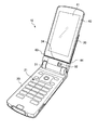
図1〜図4は回転しながらスライドする機構を有する携帯電話機の外観を示す図であり、図1は、表示ユニットを立てた状態を示す斜視図、図2は、表示ユニットを左に倒した状態を示す斜視図、図3は、表示ユニットを右に倒した状態を示す斜視図、図4は、本体ユニット上に表示ユニットを閉じた状態の斜視図である。 1 to 4 are views showing an external appearance of a mobile phone having a mechanism that slides while rotating, FIG. 1 is a perspective view showing a state in which the display unit is erected, and FIG. 2 is a view in which the display unit is tilted to the left. FIG. 3 is a perspective view showing a state where the display unit is tilted to the right, and FIG. 4 is a perspective view showing a state where the display unit is closed on the main unit.
この携帯電話機10は、本体ユニット20と、その本体ユニット20にヒンジ31を介して開閉自在に取り付けられた支持ユニット30と、その支持ユニット30に、回転およびスライド自在に支持された表示ユニット40とを有する。
The
本体ユニット20には、配列された多数のキー21が備えられており、支持ユニット30には、第1のカメラ32および第2のカメラ33(図4参照)が備えられており、表示ユニット40には、メイン画面41およびサブ画面42(図4参照)が備えられている。この携帯電話機10は、図1に示す開状態と図4に示す開状態との間で開閉するとともに表示ユニット40が、図1に示す立てた状態と、図2に示す左に倒れた状態と、図3に示す右に倒れた状態との間で回動し、これら3つの状態で安定した姿勢を維持することができる。
The
この携帯電話機10は、無線通信を使って電話による通話や電子メールの送受信等を行なうことができる。また、この携帯電話機10は、テレビのデジタル放送受像機能を有しており、テレビ受像にあたってはメイン画面41を横に倒した状態の方が見易く、このため、この携帯電話機10は表示ユニット40を横に倒すことができる構造となっている。尚、携帯電話機の機能については、ここでの主題ではなく、また広く知られているため、ここでのこれ以上の説明は省略する。
The
ところで、図1〜図4に示す携帯電話機10の表示ユニット40を例えば図1に示す立てた状態から図2に示すように左に倒そうとしたとき、表示ユニット40が、仮に、支持ユニット30に対し回転動作のみ行なえるものとした場合、表示ユニット40の下端左角43が、支持ユニット30の、表示ユニット40の下縁を支える台座部34と干渉し、図1に示す立てた状態から図2に示す左に倒れた状態に移行させることができない。このため、表示ユニット40は支持ユニット30に対し回転を行なうとともに上下にスライドする構造となっており、表示ユニット40を図1に示す立てた状態から図2に示す左に倒れた状態に移行させようとして表示ユニット40を左に回すと、表示ユニット40の下端左角43と支持ユニット30の台座部34との干渉により途中までは表示ユニット40が上にスライドしながら回転し、途中からは図示しない付勢部材の付勢により表示ユニット40が下にスライドしながら回転して図2に示す左に倒れた状態となる。表示ユニット40を図2に示す左に倒れた状態から図1に示す立てた状態に移行させる際も同様である。また、図1に示す立てた状態と図3に示す右に倒れた状態との間で回転させる場合も、今度は表示ユニット40の下端右角44が支持ユニット30の台座部34と干渉するという相違を除き、やはり回転とスライドとの双方が同時に生じることになる。
By the way, when the
近年の傾向として、携帯電話機にも防水が望まれてきており、防水型の携帯電話機も登場してきているが、上記のような回転とスライドとの双方の動きが必要となる携帯電話機については防水性能を有するものは存在しない。 In recent years, waterproofing has been desired for mobile phones, and waterproof mobile phones have also appeared. However, mobile phones that require both the above-described rotation and sliding movement are waterproof. There is nothing that has performance.
このように、従来、回転しながらスライドする機構を特徴とする電子機器においては、ヒンジモジュール自体が防水・防塵性能を持つものは存在していない。類似構造としては、油圧ピストンのオイルシールや回転軸周りのシールなどがある。しかしながらこれらの機構は、ピストンであれば直線的に一方向にだけ移動する機構であり、回転軸の場合では円周一方向にのみ回転するに過ぎない。回転しながら回転軸方向にピストン運動といった機構も存在するがシール部材の圧縮方向は軸半径方向のみである。またこれらの構造の多くは大型で、小型の電子機器には向かない。 As described above, conventionally, there is no electronic device having a waterproof / dustproof performance in an electronic device characterized by a mechanism that slides while rotating. Similar structures include an oil seal for a hydraulic piston and a seal around a rotating shaft. However, these mechanisms are mechanisms that move linearly in only one direction if they are pistons, and only rotate in one circumferential direction in the case of a rotating shaft. While there is a mechanism such as piston movement in the direction of the rotation axis while rotating, the compression direction of the seal member is only the axial radial direction. Many of these structures are large and are not suitable for small electronic devices.
特許文献1には、携帯型電子機器における防水構造が示されているが、これも回転のみ行なう構造のものであり、回転とスライドとの双方を行なう機構における防水構造は示されていない。
本発明は、上記事情に鑑み、回転するとともに回転軸とは異なる方向にスライドする機構を実現した防水型ヒンジモジュール、およびそのヒンジモジュールにより回転およびスライド自在に構成された電子機器を提供することを目的とする。 In view of the above circumstances, the present invention provides a waterproof hinge module that realizes a mechanism that rotates and slides in a direction different from the rotation axis, and an electronic device that is configured to be rotatable and slidable by the hinge module. Objective.
本発明の防水型ヒンジモジュールは、第1のヒンジ部品と、その第1のヒンジ部品に対向する第2のヒンジ部品を備え、
上記第1のヒンジ部品が、表裏に貫通した長穴と、その長穴との間にその長穴を取り巻く縁部を形成してその縁部を一周に渡って取り巻く、第2のヒンジ部品に向いて凹に形成された環状溝とを有し、その環状溝内に、防水用の環状のガスケットが、そのガスケットの厚み方向の一部が第2のヒンジ部品側に食み出した状態に装入されたものであり、
上記第2のヒンジ部材が、中央に表裏に貫通した穴を有し第1のヒンジ部品側に突出して前上記長穴に挿入され上記縁部に係止されて抜け止めされるとともにその長穴の長手方向に移動自在な筒状突起と、その筒状突起の周囲に広がって上記ガスケットの摺動を受ける摺動面とを有することを特徴とする。
The waterproof hinge module of the present invention includes a first hinge component and a second hinge component facing the first hinge component,
The first hinge part has a long hole penetrating the front and back and an edge that surrounds the long hole between the long hole and surrounds the edge all around the second hinge part. A ring-shaped groove for waterproofing, in which the gasket for waterproofing is in a state where a part of the gasket in the thickness direction protrudes to the second hinge part side. Is the one that was
The second hinge member has a hole penetrating through the front and back at the center, protrudes toward the first hinge part, is inserted into the front elongated hole, is locked to the edge portion, and is prevented from coming off. And a sliding surface which spreads around the cylindrical projection and receives the sliding of the gasket.
本発明の防水型ヒンジモジュールは、長穴と筒状突起とを備え、筒状突起を中心とした回転と、筒状突起の、長穴の長手方向へのスライドとにより、回転とスライドとの双方を実現している。 The waterproof hinge module of the present invention includes a long hole and a cylindrical protrusion, and rotation and sliding are performed by rotating around the cylindrical protrusion and sliding the cylindrical protrusion in the longitudinal direction of the long hole. Both are realized.
また、本発明の防水型ヒンジモジュールは、長穴を取り巻く環状構内に環状のガスケットが装入され、そのガスケットの厚み方向の一部が環状溝から食み出して摺動面上を摺動する構成を有するため、長穴および筒状突起の穴への水の侵入が防止される。 In the waterproof hinge module of the present invention, an annular gasket is inserted into an annular premises surrounding the elongated hole, and part of the gasket in the thickness direction protrudes from the annular groove and slides on the sliding surface. Since it has a structure, the penetration | invasion of the water to the hole of a long hole and a cylindrical protrusion is prevented.
ここで、本発明の防水型ヒンジモジュールにおいて、上記第1のヒンジ部品および上記第2のヒンジ部品のうちの一方のヒンジ部品が、他方のヒンジ部品に向いて凹に形成された軌道溝を有し、他方のヒンジ部品が軌道溝内に入り込む軌道制御用ピンを有し、上記第1のヒンジ部品および上記第2のヒンジ部品が、上記長穴による筒状突起の案内と、上記軌道溝による軌道制御用ピンの案内とにより、相対的な姿勢変化の軌道が定められてなるものであることが好ましい。 Here, in the waterproof hinge module of the present invention, one of the first hinge part and the second hinge part has a raceway groove formed in a recess toward the other hinge part. The other hinge part has a track control pin that enters the raceway groove, and the first hinge part and the second hinge part are guided by the cylindrical projection by the elongated hole and by the raceway groove. It is preferable that the trajectory of the relative posture change is determined by the guide of the trajectory control pin.
上記の軌道溝と軌道制御用ピンを備えると、回転とスライドによる姿勢の変化を一つの軌道上に規制することができる。 When the track groove and the track control pin are provided, a change in posture due to rotation and slide can be restricted on one track.
尚、軌道溝は、第1のヒンジ部品と第2のヒンジ部品のいずれのヒンジ部品に設けられていてもよく、軌道制御用ピンは軌道溝が設けられたヒンジ部品とは異なるもう一方のヒンジ部品に設けられる。 The track groove may be provided in any one of the first hinge component and the second hinge component, and the track control pin is the other hinge different from the hinge component provided with the track groove. Provided on parts.
また、本発明の防水型ヒンジモジュールにおいて、上記筒状突起が、摺動用スペーサを介在させて上記縁部に係止されたものであることが好ましい。 In the waterproof hinge module of the present invention, it is preferable that the cylindrical protrusion is locked to the edge portion with a sliding spacer interposed.
摺動用スペーサを介在させることにより、ガスケットの圧縮量を一定に保つことができ、安定した回転やスライドが実現できる。 By interposing the sliding spacer, the compression amount of the gasket can be kept constant, and stable rotation and sliding can be realized.
ここで、上記摺動用スペーサの、筒状突起が長穴内で移動したときに隣接部品との間で摺動する側の面が、弧状に形成されていることが更に好ましい。 Here, it is more preferable that the surface of the sliding spacer on the side that slides between adjacent parts when the cylindrical projection moves in the elongated hole is formed in an arc shape.
摺動用スペーサとしては例えば樹脂等からなる摺動抵抗の低い材質のものが利用されるが、その摺動用スペーサを弧状に形成することによって摺動抵抗をさらに低減し、さらに円滑な回転・スライドを実現することができる。 As the sliding spacer, a material having a low sliding resistance made of resin or the like is used. However, by forming the sliding spacer in an arc shape, the sliding resistance is further reduced, and smoother rotation / sliding is achieved. Can be realized.
また、本発明の防水型ヒンジモジュールにおいて、上記摺動面が、第1のヒンジ部品と第2のヒンジ部品の相対的な移動軌跡の全域で、ガスケットの環状の全周を受ける広がりを有するものであることが好ましい。 Further, in the waterproof hinge module of the present invention, the sliding surface has a spread to receive the entire circumference of the gasket in the entire relative movement locus of the first hinge part and the second hinge part. It is preferable that
摺動面が、移動軌跡の全域でガスケットの全周を受ける広がりを有することで、第1のヒンジ部品と第2のヒンジ部品がどのように移動しても防水性能が確実に維持される。 Since the sliding surface has a spread that receives the entire circumference of the gasket over the entire movement locus, the waterproof performance is reliably maintained regardless of how the first hinge part and the second hinge part move.
さらに、本発明の防水型ヒンジモジュールにおいて、上記軌道制御用ピンが軌道溝底面に接する長さを有し、第1のヒンジ部品と第2のヒンジ部品との間隔の規制を担うものであることが好ましい。 Furthermore, in the waterproof hinge module of the present invention, the track control pin has a length in contact with the bottom surface of the track groove and is responsible for regulating the distance between the first hinge component and the second hinge component. Is preferred.
こうすることにより、第1のヒンジ部品と第2のヒンジ部品との間隔が一定に保たれ、円滑な動きが確保される。 By doing so, the distance between the first hinge part and the second hinge part is kept constant, and smooth movement is ensured.
また、本発明の防水型ヒンジモジュールにおいて、第1ヒンジ部品が、長穴の端面に配置された摺動用部材を有するものであることが好ましく、上記一方のヒンジ部品が、軌道溝側壁に配置された摺動用部材を有するものであることが好ましく、上記摺動面が、ガスケットとの摺動摩擦低減処理が施された面であることが好ましい。 In the waterproof hinge module of the present invention, it is preferable that the first hinge part has a sliding member arranged on the end face of the elongated hole, and the one hinge part is arranged on the side wall of the raceway groove. The sliding surface is preferably a surface that has been subjected to a sliding friction reduction process with the gasket.
これらの場合、部品間の摩擦力が低減し、一層円滑な回転・スライドが実現できる。 In these cases, the frictional force between the parts is reduced, and smoother rotation and sliding can be realized.
また、本発明の防水型ヒンジモジュールにおいて、上記筒状突起が、第1のヒンジ部品と第2のヒンジ部品との間隔を規定するスペーサを挟んで上記縁部に係止されたものであることが好ましい。 Further, in the waterproof hinge module of the present invention, the cylindrical protrusion is locked to the edge portion with a spacer defining a distance between the first hinge part and the second hinge part. Is preferred.
上記のスペーサを挟むことにより、製造時にそのスペーサの厚みを調整することでガスケットの圧縮量を適正に調整することができ、防水性の維持と回転・スライドの動きの円滑さを高い次元で両立させることができる。 By sandwiching the above spacer, the compression amount of the gasket can be adjusted properly by adjusting the thickness of the spacer at the time of manufacture, and both waterproof maintenance and smoothness of rotation and slide movement are achieved at a high level. Can be made.
さらに、本発明の防水型ヒンジモジュールにおいて、上記筒状突起を長穴の一方の端に向けて付勢する付勢部材を有することが好ましく、その付勢部材はバネであってもよい。 Furthermore, the waterproof hinge module of the present invention preferably includes a biasing member that biases the cylindrical protrusion toward one end of the elongated hole, and the biasing member may be a spring.
このような付勢部材を備えると第1のヒンジ部品と第2のヒンジ部品の姿勢を一層安定に保つことができる。 With such an urging member, the postures of the first hinge part and the second hinge part can be kept more stable.
また、本発明の電子機器は、上記のいずれかの態様のヒンジモジュールを有する電子機器であって、
上記長穴に連通する第1の開口を有し第1のヒンジ部品に固定された第1のケースと、
上記筒状突起の穴に連通する第2の開口を有し第2のヒンジ部品に固定された第2のケースと、
上記第1の開口、上記筒状突起の穴、および上記第2の開口を通って第1のケース内部と第2のケース内部との間に延びるケーブルとを有することを特徴とする。
Moreover, the electronic device of the present invention is an electronic device having the hinge module according to any one of the above aspects,
A first case having a first opening communicating with the elongated hole and fixed to the first hinge part;
A second case having a second opening communicating with the hole of the cylindrical protrusion and fixed to the second hinge part;
It has a cable which extends between the inside of the 1st case and the inside of the 2nd case through the 1st opening, the hole of the cylindrical projection, and the 2nd opening.
本発明の電子機器は、上記の構成により第1のケースと第2のケースを相対的に回転およびスライドさせることができ、また、第1のケース内部と第2のケース内部をケーブルで接続しそのケーブルを介して信号の送受信を行なうことができる。 According to the electronic device of the present invention, the first case and the second case can be relatively rotated and slid by the above-described configuration, and the inside of the first case and the inside of the second case are connected by a cable. Signals can be transmitted and received through the cable.
ここで、本発明の電子機器において、上記第1のケースが、第1の開口の周りを一巡する形状の第1の防水用両面テープを挟んで第1のヒンジ部品に固定されたものであり、
上記第2のケースが、第2の開口の周りを一巡する形状の第2の防水用両面テープを挟んで第2のヒンジ部品に固定されたものであることが好ましい。
Here, in the electronic device of the present invention, the first case is fixed to the first hinge part with the first waterproof double-sided tape having a shape that goes around the first opening. ,
It is preferable that the second case is fixed to the second hinge part with a second waterproof double-sided tape shaped so as to go around the second opening.
こうすることにより第1のケースと第1のヒンジ部品との間、および第2のケースと第2のヒンジ部品との間も防止性が維持される。 By doing so, the prevention is also maintained between the first case and the first hinge part and between the second case and the second hinge part.
あるいは、本発明の電子機器において、上記第1のケースが、第1の開口の周りを一巡する形状の第1の防水用シール又は接着剤を挟んで第1のヒンジ部品に固定されたものであり、上記第2のケースが、第2の開口の周りを一巡する形状の第2の防水用シール又は接着剤を挟んで第2のヒンジ部品に固定されたものであってもよく、あるいは、
上記第1のケースが、第1の開口を一巡する形状に第1のヒンジ部品に熱溶着されることにより、第1の開口への水の侵入が防止されたものであり、上記第2のケースが、第2の開口を一巡する形状に、第2のヒンジ部品に熱溶着されることにより、第2の開口への水の侵入が防止されたものであってもよい。
Alternatively, in the electronic device of the present invention, the first case is fixed to the first hinge part with a first waterproof seal or adhesive having a shape that goes around the first opening. Yes, the second case may be fixed to the second hinge part with a second waterproof seal or adhesive having a shape around the second opening, or
The first case is heat-welded to the first hinge part in a shape that goes around the first opening, thereby preventing water from entering the first opening. The case may be one in which water intrusion into the second opening is prevented by being thermally welded to the second hinge part in a shape that goes around the second opening.
このような構成によっても、第1のケースと第1のヒンジ部品との間、および第2のケースと第2のヒンジ部品との間の防止性能が維持される。 Even with such a configuration, the prevention performance between the first case and the first hinge part and between the second case and the second hinge part is maintained.
さらに、本発明の電子機器において、上記第1のケースがネジ止め用の第1の貫通穴を有するとともに第1のヒンジ部品が貫通した第1のネジ穴を有し、この第1のケースが、第1のヒンジ部品に、第1の貫通穴と第1のネジ穴とを使ってネジ止めされたものであって、第1のヒンジ部品が、第1のネジ穴の第2のヒンジ部品側の開口を塞ぐ第1の防水部材を有し、
上記第2のケースがネジ止め用の第2の貫通穴を有するとともに第2のヒンジ部品が貫通した第2のネジ穴を有し、この第2のケースが、第2のヒンジ部品に、第2の貫通穴と第2のネジ穴を使ってネジ止めされたものであって、第2のヒンジ部品が、第2のネジ穴の第1のヒンジ部品側の開口を塞ぐ第2の防水部材を有するものであってもよい。
Furthermore, in the electronic device of the present invention, the first case has a first through hole for screwing and a first screw hole through which the first hinge part passes, and the first case has The first hinge part is screwed using the first through hole and the first screw hole, and the first hinge part is the second hinge part of the first screw hole. A first waterproof member that closes the opening on the side;
The second case has a second through hole for screwing and a second screw hole through which the second hinge part passes, and the second case is connected to the second hinge part. A second waterproof member that is screwed using two through holes and a second screw hole, and in which the second hinge part closes the opening of the second screw hole on the first hinge part side It may have.
ネジ止めの構成であっても、上記の第1の防水部材、第2の防水部材を備えることにより防水性能が維持される。 Even if it is the structure of screwing, waterproof performance is maintained by providing said 1st waterproof member and 2nd waterproof member.
以上の本発明によれば、回転とスライドとの双方の動きを実現し、かつ防水性を付与することができる。 According to the present invention described above, it is possible to realize both movements of rotation and slide and to provide waterproofness.
以下、本発明の実施形態について説明する。 Hereinafter, embodiments of the present invention will be described.
尚、以下では、本発明の電子機器の一実施形態として携帯電話機について説明するが、外観および外観から見た部品の動きは、図1〜図4に示した携帯電話機と同じであり、ここでは図1〜図4をそのまま援用することとし、携帯電話機の外観や外観上の動きについての重複説明は省略する。 In the following, a mobile phone will be described as an embodiment of the electronic apparatus of the present invention. However, the appearance and the movement of components as seen from the appearance are the same as those of the mobile phone shown in FIGS. 1 to 4 are used as they are, and redundant description of the appearance and movement of the mobile phone is omitted.
図5は、図1〜図4に示す携帯電話機10の支持ユニットと表示ユニットとの間に配置されたヒンジモジュールを示す図である。
FIG. 5 is a view showing a hinge module arranged between the support unit and the display unit of the
ここで、図1〜図4に示す支持ユニット30のヒンジモジュール100への取付けに関係する部分を第1のケース300と称し、図1〜図4に示す表示ユニット40のヒンジモジュール100の取付けに関係する部分を第2のケース400と称している。
Here, a portion related to the attachment of the
図5(A)は、ヒンジモジュールを、第1のケース側(図4の上方から支持部材30を透過して見た側)から見て示した平面図、図5(B)は、図5(A)に示す矢印A−Aに沿う断面図、図5(C)は、図5(A)に示す矢印B−Bに沿う断面図である。但し、図5(A)に示す平面図において、図示の煩雑さを避けるため、例えば、図5(B)に示す開口301等、一部の図示を省略してある。図5(B),図5(C)についても同様である。
5A is a plan view showing the hinge module as seen from the first case side (the side seen through the
このヒンジモジュール100は、支持ユニット30(図1〜図4参照)の一部を成す第1のケース300に固定された、板状の第1のヒンジ部品110と、表示ユニット40(図1〜図4参照)の一部を成す第2のケース400に固定された、第1のヒンジ部品110と対向して広がる板状の第2のヒンジ部品120とから構成されている。第1のケース300は、第1のヒンジ部品110の中央が覗くように形成された大きな開口301を有し、第2のケース400は、後述する筒状突起121の穴121aの囲りだけ開いた開口401を有する。
The
また、図6は、ヒンジモジュールの分解斜視図である。 FIG. 6 is an exploded perspective view of the hinge module.
図6には、図5に示す第1のケース200および第2のケース300は図示されていないが、第1のケース200は、図6の上方に示す防水性両面テープ132の上に位置し、第2のケース300は、図6の下方に示す防水性両面テープ142の下に位置する。
Although the first case 200 and the
以下、図5と図6を参照しながら、本実施形態のヒンジモジュールについて説明する。 Hereinafter, the hinge module of the present embodiment will be described with reference to FIGS. 5 and 6.
第1のヒンジ部品110は、中央に表裏に貫通した長穴111と、その長穴111との間にその長穴111を取り巻く縁部112を形成してその縁部112を一周に渡って取り巻く環状溝113とを有する。この環状溝113は、第2のヒンジ部品120に向いて凹に形成されており、この環状溝113内には防水用の環状のガスケット137が装入されている。このガスケット137の厚みは、環状溝113の深さよりも厚く、このため、このガスケット137の厚み方向の一部は第2のヒンジ部品120側に食み出し、第2のヒンジ部品120の、後述する摺動面122に当たり、第1のヒンジ部品110と第2のヒンジ部品120の相対的な動きにより、その摺動面122上を摺動し、第1のヒンジ部品110と第2のヒンジ部品120とに挟まれた隙間からの、そのガスケット137の内側への水の侵入を防止している。
The
また、第1のヒンジ部品110には、第2のヒンジ部品120に向いて凹に形成された軌道溝114を有する。この軌道溝114には、第2のヒンジ部品120側の軌道制御用ピン140が嵌入している。この軌道制御用ピン140は、第2のヒンジ部品120に設けられた穴123を貫通したネジ141により第2のヒンジ部品120に固定されている。
Further, the
さらに、第1のヒンジ部品110には、その周縁部分に4つのネジ穴115が設けられている。
Further, the
この第1のヒンジ部品110の裏面には、図6に示すような形状の防水用両面テープ132が置かれる。この防水用両面テープ132は、その中央部分に、第1のヒンジ部品110に形成された環状溝113および軌道溝114の裏面側の突起を避けるように形成された大きな穴132aを有し、さらにその周囲に、ネジ131を貫通させるための4つの穴132bを有する。第1のヒンジ部品110の裏面110には、その防水用両面テープ132が置かれ、さらにその第1のヒンジ部品110との間にその防水用両面テープ132を挟むように、第1のケース200(図6には不図示、図5参照)が置かれ、その第1のケース200が4本のネジ131で、防水用両面テープ132を間に挟んで第1のヒンジ部品110にネジ止めされる。第1のヒンジ部品110のネジ穴115は、その第1のヒンジ部品110の表裏に貫通したネジ穴であり、このネジ穴115にネジ131が螺入されていてもこのままでは水圧がかかるとそのネジ穴115から水が侵入するおそれがあり、したがってここでは、ネジ穴115の表面側(第2のヒンジ部品120側)がネジ穴防水テープ136で塞がれる。
A waterproof double-
次に第2のヒンジ部材120について説明する。
Next, the
第2のヒンジ部材120は、その中央部分に第2のヒンジ部材120の表裏に貫通した穴121aを有し第1のヒンジ部品110側に突出した筒状突起121を有する。この筒状突起121は、第1のヒンジ部品110に形成された長穴111に挿入され、その長穴111の周囲に形成された縁部112に係止されて抜け止めされる。具体的には、その縁部112の裏面側(第2のヒンジ部品120側を向いた表面に対する裏面)には、摺動用スペーサ138が置かれ、筒状突起121は長穴111を貫通するとともに長穴111に入り込む大きさのスペーサ134を貫通し、さらにカシメ部品133が貫通してその状態でカシメ加工される。これにより筒状突起121は、長穴111を貫通した状態のまま縁部112に係止されて長穴111からの抜けが防止される。ただし、この筒状突起121は長穴111に挿入された状態で、長穴111の長手方向に移動し、また回転することができる。
The
ここで、筒状突起121の穴121aには、信号伝達用のケーブル(図示せず)が通され、そのケーブルは、第1のケース300に形成された開口301を通ってその第1のケース300を含む支持ユニット30(図1〜図4参照)の内部にまで延びるとともに、第2のケース400に形成された開口401を通ってその第2のケース400を含む表示ユニット40(図1〜図4参照)の内部にまで延びている。
Here, a signal transmission cable (not shown) is passed through the
第2のヒンジ部品120の、中央の筒状突起121の周囲には、前述したように、第1のヒンジ部品110に形成された環状溝113に嵌入したガスケット137の摺動を受ける摺動面122を有する。この摺動面122は、第1のヒンジ部品110と第2のヒンジ部品120の相対的な移動軌跡の全域で、ガスケット137の環状の全周を受ける広がりを有するものであり、第1のヒンジ部品110と第2のヒンジ部品120が相対的にどのような姿勢にあってもガスケット137の内側への水の侵入が防止される。この摺動面122には、ガスケット137が押圧されることによる防水性と第1のヒンジ部品110と第2のヒンジ部品120が相対的に回転およびスライドする際の動きの円滑さを高い次元で両立させるために、テフロン(登録商標)加工等の表面処理が施されている。あるいはこのような表面処理に代えて、摺動面122にテフロン(登録商標)テープ等低摩擦部品が貼着されていてもよく、あるいはグリス塗布により同等の性能を与えてもよい。
As described above, the sliding surface that receives the sliding of the
また、第2のヒンジ部品120には、これも前述したようにネジ141が貫通する穴123を有し、その穴123を貫通したネジ141により軌道制御用ピン140が第2のヒンジ部品120に固定され、この軌道制御用ピン140は、第1のヒンジ部品110に形成された軌道溝114に嵌入し、その軌道溝114に案内される。この軌道制御用ピン140は、軌道溝114に嵌入してその軌道溝114の底面に接し、第1のヒンジ部品110と第2のヒンジ部品120との間隔の規制の一翼も担っている。
Further, as described above, the
ここで、第1のヒンジ部品110と第2のヒンジ部品120は、長穴111に筒状突起121が入り込んでその筒状突起121がその長穴111に案内されることと軌道溝114内に軌道制御用ピン140が入り込んでその軌道制御用ピン140が軌道溝114に案内されることで、第1のヒンジ部品110と第2のヒンジ部品120の相対的な姿勢変化の軌道が定められている。
Here, in the
また、第2のヒンジ部品120にはその周縁部分に4つのネジ穴124が形成されている。第2のヒンジ部品120の裏面(第1のヒンジ部品110に向けた面を表面とし、その反対側の裏面)には、筒状突起121の穴121aを避けるように穴142aが形成された防水用両面テープ142が配置され、さらに第2のヒンジ部品120との間に防水用両面テープ142を挟むように第2のケース300(図6には不図示、図5参照)が配置され、第2のケース300が、4本のネジ143により、防水用両面テープ142と、各ネジ143に対応し各ネジ143が貫通した、円環状のネジ穴防水テープ144とを間に挟んだ状態で、第2のヒンジ部品120にネジ止め固定される。この第2のヒンジ部品120に形成されたネジ穴124は、第2のヒンジ部品120の表裏に貫通しており、第1のヒンジ部品110のネジ穴115の場合と同様、ネジ穴124からの水の侵入を防止するため、ネジ穴124の表側(第1のヒンジ部品110側)の開口がネジ穴防水テープ139で塞がれている。
The
図7は、図5(B)に示すヒンジモジュールの断面の一部分の拡大図、図8は、図7の円R1内を更に拡大して示した図である。 FIG. 7 is an enlarged view of a part of the cross section of the hinge module shown in FIG. 5B, and FIG. 8 is an enlarged view of the inside of the circle R1 in FIG.
第2のヒンジ部品120に形成された筒状突起121は、スペーサ134およびカシメ部品133を挟んでカシメ加工されており、また、カシメ部品133と第1のヒンジ部品110との間には摺動用スペーサ138が介在している。スペーサ134は、第1のヒンジ部品110と第2のヒンジ部品120との間隔を定める役割りを担っており、このスペーサ134をカシメ部品133とは別部品としておき、製造段階でそのスペーサ134の厚さを適切に選択することにより、第1のヒンジ部品110と第2のヒンジ部品120の間隙寸法が適切に設定される。
The
また摺動用スペーサ138は摩擦抵抗の低い、例えばポリアセタール(POM)等の材料のものが使用され、長穴111内での筒状突起121のスライドや回転を円滑にしている。
The sliding
図9は、摺動用スペーサの変形例を示す図である。 FIG. 9 is a view showing a modification of the sliding spacer.
摺動用スペーサ138は、カシメ部品133との間で摺動するが、図9に示す変形例の場合、その摺動用スペーサ138のカシメ部品133側の摺動面が円弧状に形成されている。このような円弧状に形成すると摩擦抵抗を更に低減させ、さらに円滑な動きが可能となる。
The sliding
尚、摺動用スペーサは、カシメ部品133の外形に適合した形状とし、カシメ部品133に固定してもよく、その場合は摺動用スペーサ138は第1のヒンジ部品110との間で摺動することになり、この場合は、摺動用スペーサ138の、第1のヒンジ部品110側の面を円弧状に形成することが好ましい。
The sliding spacer may have a shape that matches the outer shape of the
図10は、図5(C)に示すヒンジモジュールの断面の一部分の拡大図、図11は、第1のヒンジ部品の第2のヒンジ部品側の面を示した斜視図である。 FIG. 10 is an enlarged view of a part of the cross section of the hinge module shown in FIG. 5C, and FIG. 11 is a perspective view showing a surface of the first hinge part on the second hinge part side.
図11は軌道溝114の説明用であり、この軌道溝114は深さが一定の凹形状を有している。
FIG. 11 is an illustration of the
ここで、図10には、軌道溝114に軌道制御用ピン140が入り込み、その軌道制御用ピン140が軌道溝の底面に接している状態が示されている。このように、ネジ141および軌道溝制御用ピン140の寸法を、ネジ141で軌道溝制御用ピン140を取り付けたときに、その軌道制御用ピン140が軌道溝114の底面に接する長さに形成しておくことによって、この軌道制御用ピン140に、軌道溝114に案内されて回転やスライドの動作を規定する役割りに加え、さらに第1のヒンジ部品110と第2のヒンジ部品120の間隔を規定する役割りを担わせることができる。
Here, FIG. 10 shows a state in which the
図12は、図5(A)にも示すヒンジモジュールの平面図であり、図13の切断面を示すために再掲した図、図13は、図12に示す矢印A−Aの断面の一部分の拡大図である。 12 is a plan view of the hinge module also shown in FIG. 5 (A), and is a diagram reprinted to show the cut surface of FIG. 13, and FIG. 13 is a part of the cross section of the arrow AA shown in FIG. It is an enlarged view.
図13に示すように第1のケース300と第1のヒンジ部品110とをネジ131でネジ止めするための、第1のヒンジ部品110に形成されたネジ穴115は、第2のヒンジ部品120側の開口が広がっており、その開口には、ネジ穴防水テープ136が貼着されている。これにより、ネジ穴115からの浸水や塵埃の侵入が防止される。
As shown in FIG. 13, the
尚、ここでは、第1のヒンジ部品110のネジ穴115とそのネジ穴115を塞ぐネジ穴防水テープ136について説明したが、図6に示す第2のヒンジ部品120のネジ穴124とそのネジ穴124を塞ぐネジ穴防水テープ139についても同様である。
Here, the
図14は、付勢バネを明示的に示した図である。図14(A)では第1のケース300に対し第2のケース400が立設した状態にあり、図14(B)では第1のケース300に対し第2のケース400が横に倒れた状態にある。
FIG. 14 is a diagram explicitly showing the biasing spring. In FIG. 14A, the
ここにはバネ144が示されており、このバネ144は、筒状突起121を、長穴111内の、常に軌道溝114に寄った方向(図に示す矢印X方向)に付勢している。このため、第2のケース400を矢印Y方向に回転させようとしたとき、回転途中で手を離しても、第2のケース400は、図14(A)に示す立設した位置又は図14(B)に示す横に倒れた位置に自ずと移動する。したがって、第2のケース400は、図14(A)に示す立位置、図14(B)に示す横位置、および、図示は省略したが、第2のケース400が図14(B)とは逆方向に倒れた横位置の3つの位置で安定することになる(図1〜図3参照)。
Here, a
尚、この図14ではコイルバネを示したがコイルバネに限らず板バネ等を用いてもよく、また、この図14に示すバネの取付位置は一例であって、バネの取付位置はそのバネの形状等に応じて変更される。 Although FIG. 14 shows a coil spring, not only the coil spring but also a leaf spring or the like may be used, and the attachment position of the spring shown in FIG. 14 is an example, and the attachment position of the spring is the shape of the spring. It changes according to etc.
次に上記の実施形態の変形例について説明する。 Next, a modification of the above embodiment will be described.
図15は、第1のヒンジと第2のヒンジとを組み合わせた状態の斜視図、図16は、第1のヒンジ部品の、第2のヒンジ部品側を向いた面を示す斜視図である。 FIG. 15 is a perspective view showing a state in which the first hinge and the second hinge are combined, and FIG. 16 is a perspective view showing a surface of the first hinge part facing the second hinge part.
ここで、図15(A)は、第2のヒンジ部品側から見た斜視図、図15(B)は、第1のヒンジ部品側から見た斜視図である。 Here, FIG. 15A is a perspective view seen from the second hinge part side, and FIG. 15B is a perspective view seen from the first hinge part side.
また、図17は、第1のヒンジ部品と第2のヒンジ部品とを組合せた状態を示す図であり、図17(A)は第1のヒンジ部品側から見た平面図、図17(B)は図17(A)に示す矢印A−Aに沿う断面図、図17(C)は、図17(A)に示す矢印B−Bに沿う断面図である。 FIG. 17 is a view showing a state in which the first hinge part and the second hinge part are combined. FIG. 17A is a plan view seen from the first hinge part side, and FIG. ) Is a cross-sectional view taken along the arrow AA shown in FIG. 17A, and FIG. 17C is a cross-sectional view taken along the arrow BB shown in FIG.
さらに、図18は、図17(B)に示す断面図の一部分の拡大図である。 Further, FIG. 18 is an enlarged view of a part of the cross-sectional view shown in FIG.
これらの図15〜図18に示すように、長穴111の端面には潤滑性の良い樹脂からなる摺動部材151が配置されており、またこれと同様に軌道溝114の側壁にも潤滑性の良い樹脂からなる摺動部材152が配置されている。ここで潤滑性の良い摺動部材151,152としては、例えばポリアセタール(POM)やテフロン(登録商標)樹脂などが利用可能である。
As shown in FIGS. 15 to 18, a sliding
この摺動部材151を長穴111の端面に配置すると、第1のヒンジ部品110の長穴111と第2のヒンジ部品120の筒状突起121との間の摩擦が低減され、また、摺動部材152を軌道溝114の側壁に配置すると、第1のヒンジ部品110の軌道溝114と第2のヒンジ部品120側の軌道制御用ピン140との間の摩擦が低減され、いずれの場合も、第1のヒンジ部品110と第2のヒンジ部品120の相対的な回転やスライドの動作が一層円滑となる。
When the sliding
また、前述の実施形態では、図6に示す防水用両面テープ132で第1のケース300(図5参照)と第1のヒンジ部品110との間の防水を担い、もう1つの防水用両面テープ142で、第2のケース400(図5参照)と第2のヒンジ部品120との間の防水を担っているが、それらの両面テープ132,142に代えて、第1のケース300がその第1のケースの開口301の周りを一巡する形状の防水用シール又は接着剤層を挟んで第1のヒンジ部品110に固定され、これと同様に、第2のケース400がその第2のケースの開口401の周りを一巡する形状の防水用シール又は接着剤層を挟んで第2のヒンジ部品120に固定され、これにより、第1のケース300と第1のヒンジ部品110との間、および、第2のケース400と第2のヒンジ部品120との間の防水性を確保してもよい。あるいは、さらに別の変形例として、第1のケース300が、その第1のケースの開口301を一巡する形状に第1のヒンジ部品110に熱溶着されることにより、第1のケースの開口301への水の侵入が防止されたものであり、第2のケース400が、その第2のケースの開口401を一巡する形状に、第2のヒンジ部品120に熱溶着されることにより、その第2のケースの開口401への水の侵入が防止されたものであってもよい。
In the above-described embodiment, the waterproof double-
このように、第1のケース300と第1のヒンジ部材110との間、および第2のケース400と第2のヒンジ部材120との間は、様々な手段により防水性を確保することができる。
As described above, waterproofness can be ensured between the
尚、ここでは、本発明の防水型電子機器の一例として携帯電話機について説明したが、本発明は、携帯電話機に限られるものではなく、回転とスライドとの双方の動きを必要とする電子機器に広く採用することができる。 Here, the mobile phone has been described as an example of the waterproof electronic device of the present invention. However, the present invention is not limited to the mobile phone, and the electronic device requires both rotation and slide movement. Can be widely adopted.
以下、本発明の各種形態を付記する。 Hereinafter, various embodiments of the present invention will be additionally described.
(付記1)
第1のヒンジ部品と、該第1のヒンジ部品に対向する第2のヒンジ部品を備え、
前記第1のヒンジ部品が、表裏に貫通した長穴と、該長穴との間に該長穴を取り巻く縁部を形成して該縁部を一周に渡って取り巻く、前記第2のヒンジ部品に向いて凹に形成された環状溝とを有し、該環状溝内に、防水用の環状のガスケットが、該ガスケットの厚み方向の一部が前記第2のヒンジ部品側に食み出した状態に装入されたものであり、
前記第2のヒンジ部材が、中央に表裏に貫通した穴を有し前記第1のヒンジ部品側に突出して前記長穴に挿入され前記縁部に係止されて抜け止めされるとともに該長穴の長手方向に移動自在な筒状突起と、該筒状突起の周囲に広がって前記ガスケットの摺動を受ける摺動面とを有することを特徴とする防水型ヒンジモジュール。
(Appendix 1)
A first hinge part and a second hinge part facing the first hinge part;
The first hinge part is formed with an elongated hole penetrating front and back and an edge surrounding the elongated hole between the elongated hole and surrounding the edge part around the circumference. An annular groove formed in a concave shape facing the inside of the annular groove, and a waterproof annular gasket protrudes partly in the thickness direction of the gasket toward the second hinge part. Is in charge of the state,
The second hinge member has a hole penetrating through the front and back at the center, protrudes toward the first hinge part, is inserted into the elongated hole, is locked to the edge portion, and is prevented from coming off. A waterproof hinge module comprising: a cylindrical projection that is movable in the longitudinal direction; and a sliding surface that extends around the cylindrical projection and receives the sliding of the gasket.
(付記2)
前記第1のヒンジ部品および前記第2のヒンジ部品のうちの一方のヒンジ部品が、他方のヒンジ部品に向いて凹に形成された軌道溝を有し、他方のヒンジ部品が前記軌道溝内に入り込む軌道制御用ピンを有し、前記第1のヒンジ部品および前記第2のヒンジ部品が、前記長穴による前記筒状突起の案内と、前記軌道溝による前記軌道制御用ピンの案内とにより、相対的な姿勢変化の軌道が定められてなるものであることを特徴とする付記1記載の防水型ヒンジモジュール。
(Appendix 2)
One hinge part of the first hinge part and the second hinge part has a raceway groove that is recessed toward the other hinge part, and the other hinge part is in the raceway groove. A trajectory control pin that enters, and the first hinge part and the second hinge part are guided by the cylindrical projection by the elongated hole and by the guide of the trajectory control pin by the raceway groove, The waterproof hinge module as set forth in appendix 1, wherein a trajectory of relative posture change is defined.
(付記3)
前記筒状突起が、摺動用スペーサを介在させて前記縁部に係止されたものであることを特徴とする付記1又は2記載の防水型ヒンジモジュール。
(Appendix 3)
The waterproof hinge module according to appendix 1 or 2, wherein the cylindrical projection is locked to the edge with a sliding spacer interposed.
(付記4)
前記摺動用スペーサの、前記筒状突起が前記長穴内で移動したときに隣接部品との間で摺動する側の面が、弧状に形成されていることを特徴とする付記3記載の防水型ヒンジモジュール。
(Appendix 4)
The waterproof mold according to appendix 3, wherein a surface of the sliding spacer on the side that slides between adjacent parts when the cylindrical protrusion moves in the elongated hole is formed in an arc shape. Hinge module.
(付記5)
前記摺動面が、前記第1のヒンジ部品と前記第2のヒンジ部品の相対的な移動軌跡の全域で、前記ガスケットの環状の全周を受ける広がりを有するものであることを特徴とする付記1又は2記載の防水型ヒンジモジュール。
(Appendix 5)
Note that the sliding surface has a width for receiving the entire circumference of the gasket in the entire relative movement locus of the first hinge part and the second hinge part. The waterproof hinge module according to 1 or 2.
(付記6)
前記軌道制御用ピンが前記軌道溝底面に接する長さを有し、前記第1のヒンジ部品と前記第2のヒンジ部品との間隔の規制を担うものであることを特徴とする付記2記載の防水型ヒンジモジュール。
(Appendix 6)
The supplementary note 2, wherein the track control pin has a length in contact with the bottom surface of the track groove, and is responsible for regulating a distance between the first hinge part and the second hinge part. Waterproof hinge module.
(付記7)
前記第1ヒンジ部品が、前記長穴の端面に配置された摺動用部材を有するものであることを特徴とする付記1又は2記載の防水型ヒンジモジュール。
(Appendix 7)
The waterproof hinge module according to appendix 1 or 2, wherein the first hinge part has a sliding member disposed on an end face of the elongated hole.
(付記8)
前記一方のヒンジ部品が、前記軌道溝側壁に配置された摺動用部材を有するものであることを特徴とする付記2記載の防水型ヒンジモジュール。
(Appendix 8)
The waterproof hinge module according to appendix 2, wherein the one hinge component has a sliding member disposed on the side wall of the raceway groove.
(付記9)
前記摺動面が、前記ガスケットとの摺動摩擦低減処理が施された面であることを特徴とする付記1又は2記載の防水型ヒンジモジュール。
(Appendix 9)
The waterproof hinge module according to appendix 1 or 2, wherein the sliding surface is a surface subjected to a sliding friction reduction process with the gasket.
(付記10)
前記筒状突起が、前記第1のヒンジ部品と前記第2のヒンジ部品との間隔を規定するスペーサを挟んで前記縁部に係止されたものであることを特徴とする付記1又は2記載の防水型ヒンジモジュール。
(Appendix 10)
The supplementary note 1 or 2, wherein the cylindrical protrusion is locked to the edge portion with a spacer defining an interval between the first hinge part and the second hinge part interposed therebetween. Waterproof hinge module.
(付記11)
前記筒状突起を前記長穴の一方の端に向けて付勢する付勢部材を有することを特徴とする付記1又は2記載の防水型ヒンジモジュール。
(Appendix 11)
The waterproof hinge module according to appendix 1 or 2, further comprising a biasing member that biases the cylindrical projection toward one end of the elongated hole.
(付記12)
前記付勢部材がバネであることを特徴とする付記11記載の防水型ヒンジモジュール。
(Appendix 12)
The waterproof hinge module according to appendix 11, wherein the biasing member is a spring.
(付記13)
付記1から3のうちのいずれか1項記載のヒンジモジュールを有する電子機器であって、
前記長穴に連通する第1の開口を有し前記第1のヒンジ部品に固定された第1のケースと、
前記筒状突起の穴に連通する第2の開口を有し前記第2のヒンジ部品に固定された第2のケースと、
前記第1の開口、前記筒状突起の穴、および前記第2の開口を通って前記第1のケース内部と前記第2のケース内部との間に延びるケーブルとを有することを特徴とする電子機器。
(Appendix 13)
An electronic apparatus having the hinge module according to any one of appendices 1 to 3,
A first case having a first opening communicating with the elongated hole and fixed to the first hinge part;
A second case having a second opening communicating with the hole of the cylindrical protrusion and fixed to the second hinge part;
An electron comprising: the first opening, the hole of the cylindrical protrusion, and a cable extending between the first case and the second case through the second opening. machine.
(付記14)
前記第1のケースが、前記第1の開口の周りを一巡する形状の第1の防水用両面テープを挟んで前記第1のヒンジ部品に固定されたものであり、
前記第2のケースが、前記第2の開口の周りを一巡する形状の第2の防水用両面テープを挟んで前記第2のヒンジ部品に固定されたものであることを特徴とする付記13記載の電子機器。
(Appendix 14)
The first case is fixed to the first hinge part with a first waterproof double-sided tape shaped to make a round around the first opening;
The supplementary note 13, wherein the second case is fixed to the second hinge part with a second waterproof double-sided tape having a shape surrounding the second opening. Electronic equipment.
(付記15)
前記第1のケースが、前記第1の開口の周りを一巡する形状の第1の防水用シール又は接着剤を挟んで前記第1のヒンジ部品に固定されたものであり、
前記第2のケースが、前記第2の開口の周りを一巡する形状の第2の防水用シール又は接着剤を挟んで前記第2のヒンジ部品に固定されたものであることを特徴とする付記13記載の電子機器。
(Appendix 15)
The first case is fixed to the first hinge part with a first waterproof seal or adhesive having a shape that goes around the first opening.
Note that the second case is fixed to the second hinge part with a second waterproof seal or adhesive having a shape that goes around the second opening. 13. The electronic device according to 13.
(付記16)
前記第1のケースが、前記第1の開口を一巡する形状に前記第1のヒンジ部品に熱溶着されることにより、該第1の開口への水の侵入が防止されたものであり、
前記第2のケースが、前記第2の開口を一巡する形状に、前記第2のヒンジ部品に熱溶着されることにより、該第2の開口への水の侵入が防止されたものであることを特徴とする付記13記載の電子機器。
(Appendix 16)
The first case is heat-welded to the first hinge part in a shape that goes around the first opening, thereby preventing water from entering the first opening.
The second case is heat-welded to the second hinge part in a shape that makes a round of the second opening, thereby preventing water from entering the second opening. Item 14. The electronic device according to appendix 13, wherein
(付記17)
前記第1のケースがネジ止め用の第1の貫通穴を有するとともに前記第1のヒンジ部品が貫通した第1のネジ穴を有し、該第1のケースが、該第1のヒンジ部品に、該第1の貫通穴と該第1のネジ穴とを使ってネジ止めされたものであって、該第1のヒンジ部品が、該第1のネジ穴の前記第2のヒンジ部品側の開口を塞ぐ第1の防水部材を有し、
前記第2のケースがネジ止め用の第2の貫通穴を有するとともに前記第2のヒンジ部品が貫通した第2のネジ穴を有し、該第2のケースが、前記第2のヒンジ部品に、該第2の貫通穴と該第2のネジ穴を使ってネジ止めされたものであって、該第2のヒンジ部品が、該第2のネジ穴の前記第1のヒンジ部品側の開口を塞ぐ第2の防水部材を有することを特徴とする付記13又は14記載の電子機器。
(Appendix 17)
The first case has a first through hole for screwing and a first screw hole through which the first hinge part passes, and the first case is connected to the first hinge part. The first hinge part is screwed by using the first through hole and the first screw hole, and the first hinge part is located on the second hinge part side of the first screw hole. A first waterproof member that closes the opening;
The second case has a second through hole for screwing and a second screw hole through which the second hinge part passes, and the second case is formed on the second hinge part. The second hinge part is screwed using the second through hole and the second screw hole, and the second hinge part is an opening on the first hinge part side of the second screw hole. 15. The electronic device according to appendix 13 or 14, further comprising a second waterproof member that closes the cover.
10 携帯電話機
20 本体ユニット
21 キー
30 支持ユニット
31 ヒンジ
32 第1のカメラ
33 第2のカメラ
34 台座部
40 表示ユニット
41 メイン画面
42 サブ画面
43 下端左角
100 ヒンジモジュール
110 ヒンジ部品
111 長穴
112 縁部
113 環状溝
114 軌道溝
115,124 ネジ穴
120 第2のヒンジ部品
121 筒状突起
121a,123,132b 穴
122 摺動面
131,141 ネジ
132,142 防水性両面テープ
133 カシメ部品
134 スペーサ
136,139 ネジ穴防水テープ
137 ガスケット
138 摺動用スペーサ
140 軌道制御用ピン
144 バネ
151,152 摺動部材
300 第1のケース
400 第2のケース
301,401 開口
DESCRIPTION OF
Claims (6)
前記第1のヒンジ部品が、表裏に貫通した長穴と、該長穴との間に該長穴を取り巻く縁部を形成して該縁部を一周に渡って取り巻く、前記第2のヒンジ部品に向いて凹に形成された環状溝とを有し、該環状溝内に、防水用の環状のガスケットが、該ガスケットの厚み方向の一部が前記第2のヒンジ部品側に食み出した状態に装入されたものであり、
前記第2のヒンジ部材が、中央に表裏に貫通した穴を有し前記第1のヒンジ部品側に突出して前記長穴に挿入され前記縁部に係止されて抜け止めされるとともに該長穴の長手方向に移動自在な筒状突起と、該筒状突起の周囲に広がって前記ガスケットの摺動を受ける摺動面とを有することを特徴とする防水型ヒンジモジュール。 A first hinge part and a second hinge part facing the first hinge part;
The first hinge part is formed with an elongated hole penetrating front and back and an edge surrounding the elongated hole between the elongated hole and surrounding the edge part around the circumference. An annular groove formed in a concave shape facing the inside of the annular groove, and a waterproof annular gasket protrudes partly in the thickness direction of the gasket toward the second hinge part. Is in charge of the state,
The second hinge member has a hole penetrating through the front and back at the center, protrudes toward the first hinge part, is inserted into the elongated hole, is locked to the edge portion, and is prevented from coming off. A waterproof hinge module comprising: a cylindrical projection that is movable in the longitudinal direction; and a sliding surface that extends around the cylindrical projection and receives the sliding of the gasket.
前記長穴に連通する第1の開口を有し前記第1のヒンジ部品に固定された第1のケースと、
前記筒状突起の穴に連通する第2の開口を有し前記第2のヒンジ部品に固定された第2のケースと、
前記第1の開口、前記筒状突起の穴、および前記第2の開口を通って前記第1のケース内部と前記第2のケース内部との間に延びるケーブルとを有することを特徴とする電子機器。 An electronic device comprising the hinge module according to any one of claims 1 to 3,
A first case having a first opening communicating with the elongated hole and fixed to the first hinge part;
A second case having a second opening communicating with the hole of the cylindrical protrusion and fixed to the second hinge part;
An electron comprising: the first opening, the hole of the cylindrical protrusion, and a cable extending between the first case and the second case through the second opening. machine.
前記第2のケースが、前記第2の開口の周りを一巡する形状の第2の防水用両面テープを挟んで前記第2のヒンジ部品に固定されたものであることを特徴とする請求項4記載の電子機器。 The first case is fixed to the first hinge part with a first waterproof double-sided tape shaped to make a round around the first opening;
5. The second case is fixed to the second hinge part with a second waterproof double-sided tape having a shape that goes around the second opening interposed therebetween. The electronic device described.
前記第2のケースがネジ止め用の第2の貫通穴を有するとともに前記第2のヒンジ部品が貫通した第2のネジ穴を有し、該第2のケースが、前記第2のヒンジ部品に、該第2の貫通穴と該第2のネジ穴を使ってネジ止めされたものであって、該第2のヒンジ部品が、該第2のネジ穴の前記第1のヒンジ部品側の開口を塞ぐ第2の防水部材を有することを特徴とする請求項4又は5記載の電子機器。 The first case has a first through hole for screwing and a first screw hole through which the first hinge part passes, and the first case is connected to the first hinge part. The first hinge part is screwed by using the first through hole and the first screw hole, and the first hinge part is located on the second hinge part side of the first screw hole. A first waterproof member that closes the opening;
The second case has a second through hole for screwing and a second screw hole through which the second hinge part passes, and the second case is formed on the second hinge part. The second hinge part is screwed using the second through hole and the second screw hole, and the second hinge part is an opening on the first hinge part side of the second screw hole. 6. The electronic device according to claim 4, further comprising a second waterproof member that closes the cover.
Priority Applications (2)
| Application Number | Priority Date | Filing Date | Title |
|---|---|---|---|
| JP2008043336A JP5082920B2 (en) | 2008-02-25 | 2008-02-25 | Waterproof hinge module and electronic equipment |
| US12/365,568 US8234754B2 (en) | 2008-02-25 | 2009-02-04 | Hinge module and electronic equipment |
Applications Claiming Priority (1)
| Application Number | Priority Date | Filing Date | Title |
|---|---|---|---|
| JP2008043336A JP5082920B2 (en) | 2008-02-25 | 2008-02-25 | Waterproof hinge module and electronic equipment |
Publications (2)
| Publication Number | Publication Date |
|---|---|
| JP2009197987A JP2009197987A (en) | 2009-09-03 |
| JP5082920B2 true JP5082920B2 (en) | 2012-11-28 |
Family
ID=40996886
Family Applications (1)
| Application Number | Title | Priority Date | Filing Date |
|---|---|---|---|
| JP2008043336A Expired - Fee Related JP5082920B2 (en) | 2008-02-25 | 2008-02-25 | Waterproof hinge module and electronic equipment |
Country Status (2)
| Country | Link |
|---|---|
| US (1) | US8234754B2 (en) |
| JP (1) | JP5082920B2 (en) |
Families Citing this family (10)
| Publication number | Priority date | Publication date | Assignee | Title |
|---|---|---|---|---|
| JP2008076818A (en) * | 2006-09-22 | 2008-04-03 | Fujitsu Ltd | Mobile terminal device |
| US7752710B2 (en) * | 2007-12-17 | 2010-07-13 | Cheng Uei Precision Industry Co., Ltd. | Sliding hinge |
| US9945423B2 (en) * | 2009-12-30 | 2018-04-17 | Provenance Asset Group Llc | Method and apparatus relating to movable assembly |
| JP5641051B2 (en) * | 2010-10-07 | 2014-12-17 | 富士通株式会社 | Mobile terminal device |
| KR20120099865A (en) * | 2011-03-02 | 2012-09-12 | 삼성전자주식회사 | Damping device for sliding-type portable terminal |
| US8825122B2 (en) * | 2011-09-21 | 2014-09-02 | Htc Corporation | Hand-held deivce |
| CN202257383U (en) * | 2011-10-10 | 2012-05-30 | 深圳市保绿源硅橡胶科技有限公司 | Support device of tablet personal computer |
| US9310837B2 (en) * | 2012-04-16 | 2016-04-12 | World Richman Manufacturing Corporation | Rotating mechanism for computer or similar device |
| US9080716B2 (en) * | 2012-04-16 | 2015-07-14 | World Richman Mfg. Corp. | Cradle apparatus and method for rotating and linearly displacing an electronic device |
| KR102642314B1 (en) * | 2018-12-06 | 2024-03-04 | 삼성전자주식회사 | Electronic device having waterproof structure |
Family Cites Families (13)
| Publication number | Priority date | Publication date | Assignee | Title |
|---|---|---|---|---|
| US2007A (en) * | 1841-03-16 | Improvement in the mode of harvesting grain | ||
| GB1482202A (en) * | 1973-12-18 | 1977-08-10 | Timber Res & Dev Ass | Door mounting |
| US6522529B1 (en) * | 2000-05-22 | 2003-02-18 | Vivek R. Huilgol | Rotatable computer display apparatus and method |
| WO2006038499A1 (en) * | 2004-10-01 | 2006-04-13 | Sharp Kabushiki Kaisha | Mobile information terminal |
| JP4336798B2 (en) * | 2004-11-29 | 2009-09-30 | 日本電気株式会社 | Waterproof structure for portable electronic device and portable electronic device having the structure |
| JP4384059B2 (en) * | 2005-01-31 | 2009-12-16 | シャープ株式会社 | Folding cell phone |
| JP2007273877A (en) * | 2006-03-31 | 2007-10-18 | Casio Hitachi Mobile Communications Co Ltd | Portable electronic device |
| JP4466630B2 (en) | 2006-03-31 | 2010-05-26 | 株式会社カシオ日立モバイルコミュニケーションズ | Hinge device and portable electronic device |
| TWI325712B (en) * | 2006-08-16 | 2010-06-01 | Htc Corp | Handheld electronic apparutus with mutiple opertaing configurations |
| US8352000B2 (en) * | 2006-08-22 | 2013-01-08 | Samsung Electronics Co., Ltd. | Mobile phone having dual connection member and hinge device thereof |
| JP4484859B2 (en) * | 2006-10-19 | 2010-06-16 | シャープ株式会社 | Sliding mobile device |
| JP4416804B2 (en) * | 2007-03-26 | 2010-02-17 | シャープ株式会社 | Mobile device |
| US7685680B2 (en) * | 2007-06-05 | 2010-03-30 | Hsiang-Chi Chien | Rotatable slide hinge |
-
2008
- 2008-02-25 JP JP2008043336A patent/JP5082920B2/en not_active Expired - Fee Related
-
2009
- 2009-02-04 US US12/365,568 patent/US8234754B2/en active Active
Also Published As
| Publication number | Publication date |
|---|---|
| JP2009197987A (en) | 2009-09-03 |
| US8234754B2 (en) | 2012-08-07 |
| US20090211057A1 (en) | 2009-08-27 |
Similar Documents
| Publication | Publication Date | Title |
|---|---|---|
| JP5082920B2 (en) | Waterproof hinge module and electronic equipment | |
| US7522946B2 (en) | Hinge apparatus for mobile communication terminals | |
| EP2031839B1 (en) | Portable information terminal | |
| KR100347110B1 (en) | Hinge device | |
| EP2242237B1 (en) | Portable electronic device | |
| US20040203535A1 (en) | Mobile phone having a rotational camera lens housing | |
| KR20110018795A (en) | Swing type portable terminal | |
| KR100689532B1 (en) | Dual axis hinge apparatus for portable terminal | |
| US8046036B2 (en) | Slide module and mobile terminal having the same | |
| US10750002B2 (en) | Communication device | |
| JP4241241B2 (en) | Hinge structure and electronic equipment | |
| JP2009171085A (en) | Electronic device | |
| KR20110012203A (en) | Portable terminal with hinge apparatus | |
| KR102120143B1 (en) | Lens module | |
| KR100842527B1 (en) | Hinge apparatus for portable terminal | |
| KR100703512B1 (en) | Camera lens assembly for portable terminal | |
| JP3874750B2 (en) | Foldable mobile terminal with slide function | |
| KR100557065B1 (en) | Mobile phone with rotational camera lens housing | |
| KR100678058B1 (en) | Hinge module and portable terminal therewith | |
| KR200326814Y1 (en) | The slide-up style of A portable telephone. | |
| JP4337492B2 (en) | Hinge device | |
| KR100692575B1 (en) | Hinge apparatus for mobile device | |
| KR200410327Y1 (en) | Hinge apparatus of mobile phone having apparatus for prevention friction | |
| KR20110005077A (en) | 2-axis hinge apparatus and portable terminal having it | |
| KR200367837Y1 (en) | Guide device for slide type portable wireless terminal |
Legal Events
| Date | Code | Title | Description |
|---|---|---|---|
| A621 | Written request for application examination |
Free format text: JAPANESE INTERMEDIATE CODE: A621 Effective date: 20100917 |
|
| A977 | Report on retrieval |
Free format text: JAPANESE INTERMEDIATE CODE: A971007 Effective date: 20120330 |
|
| TRDD | Decision of grant or rejection written | ||
| A01 | Written decision to grant a patent or to grant a registration (utility model) |
Free format text: JAPANESE INTERMEDIATE CODE: A01 Effective date: 20120807 |
|
| A01 | Written decision to grant a patent or to grant a registration (utility model) |
Free format text: JAPANESE INTERMEDIATE CODE: A01 |
|
| A61 | First payment of annual fees (during grant procedure) |
Free format text: JAPANESE INTERMEDIATE CODE: A61 Effective date: 20120820 |
|
| R150 | Certificate of patent or registration of utility model |
Ref document number: 5082920 Country of ref document: JP Free format text: JAPANESE INTERMEDIATE CODE: R150 Free format text: JAPANESE INTERMEDIATE CODE: R150 |
|
| FPAY | Renewal fee payment (event date is renewal date of database) |
Free format text: PAYMENT UNTIL: 20150914 Year of fee payment: 3 |
|
| S111 | Request for change of ownership or part of ownership |
Free format text: JAPANESE INTERMEDIATE CODE: R313113 |
|
| R350 | Written notification of registration of transfer |
Free format text: JAPANESE INTERMEDIATE CODE: R350 |
|
| R250 | Receipt of annual fees |
Free format text: JAPANESE INTERMEDIATE CODE: R250 |
|
| LAPS | Cancellation because of no payment of annual fees |