JP5082870B2 - Wristwatch with wireless function - Google Patents
Wristwatch with wireless function Download PDFInfo
- Publication number
- JP5082870B2 JP5082870B2 JP2008007766A JP2008007766A JP5082870B2 JP 5082870 B2 JP5082870 B2 JP 5082870B2 JP 2008007766 A JP2008007766 A JP 2008007766A JP 2008007766 A JP2008007766 A JP 2008007766A JP 5082870 B2 JP5082870 B2 JP 5082870B2
- Authority
- JP
- Japan
- Prior art keywords
- wristwatch
- antenna
- wireless function
- dial
- gps
- Prior art date
- Legal status (The legal status is an assumption and is not a legal conclusion. Google has not performed a legal analysis and makes no representation as to the accuracy of the status listed.)
- Active
Links
Images


Description
本発明は無線機能付腕時計に関する。 The present invention relates to a wireless function wristwatch.
近年、無線通信機能を備えた腕時計が開発されている。このような無線通信機能としては、例えばGPS:Global Positioning System等、位置情報衛星からの電波を受けて現在位置を検出する機能が利用される。
このような無線機能付腕時計においては、腕時計という条件のもとで良好な機能を確保できる通信アンテナが要求される。
In recent years, wristwatches having a wireless communication function have been developed. As such a wireless communication function, for example, a function of detecting a current position by receiving radio waves from a position information satellite such as GPS: Global Positioning System is used.
Such a wristwatch with a wireless function requires a communication antenna that can ensure a good function under the condition of a wristwatch.
特許文献1〜4には、衛星通信システムの端末機能を有する腕時計あるいは無線放送信号の送受信機能を有する腕時計が開示されている。
特許文献1では、表示部の周囲に誘電体基板を伴うC型ループアンテナを配置するとともに、腕時計の金属製本体ベースをグランドプレーンとして利用している。
特許文献2では、腕時計の表示部の隣にGPSアンテナを並べて設置している。GPSアンテナは、腕時計のメタルケースに両面テープで固定される。
In
In
特許文献3では、アンテナおよび送受信回路を一括して樹脂製のベゼルに設置し、ベゼルの着脱により腕時計に送受信機能を簡単に付加できるようにしている。アンテナはベゼルで覆われて外観上は隠される。
特許文献4では、文字板の表面にチップアンテナを設置する。チップアンテナは、外観上目立たないように、文字板上の時字に合わせて設置される。また、チップアンテナは、GPS用途の円偏波に対応するべく、複数が交差方向に配置される。
In
In Patent Document 4, a chip antenna is installed on the surface of a dial. The chip antenna is installed according to the time character on the dial so as not to stand out in appearance. A plurality of chip antennas are arranged in the crossing direction so as to correspond to circularly polarized waves for GPS use.
腕時計においては、時刻表示や通信等の実用的な機能性だけではなく、装身具としての質感が要求される。特に、指針表示の腕時計ではこの傾向が顕著である。
このような腕時計では、ケースや文字板などの外装に、精密仕上げが施された金属素材が利用される。また、通信用アンテナ等の機能要素は、外観性を損なわないように極力内装化あるいは被覆等することが要求される。
A wristwatch requires not only practical functionality such as time display and communication, but also a texture as an accessory. This tendency is particularly noticeable in wristwatches that display pointers.
In such a wristwatch, a metal material having a precision finish is used for an exterior such as a case or a dial. In addition, functional elements such as communication antennas are required to be interior-coated or covered as much as possible so as not to impair the appearance.
このような要求に対して、前述した特許文献1,2の構成は、通信用アンテナが表示部に隣接して大きく露出し、前述した質感をも考慮すると採用することができない。
また、前述した特許文献3、4の構成は、外観上の問題を生じにくいものの、十分なアンテナ性能を確保できないという問題がある。すなわち、特許文献3では、通信用アンテナが露出しないものの、グランドプレーンが確保できない。特許文献4では、文字板上での外観性は良好であるが、アンテナ有効長が確保できない。
そして、前述した金属製のケースおよび文字板は、質感上好ましい反面、その導電性により内部を電磁遮蔽する。このため、これら金属製のケースおよび文字板の内部にアンテナを収容した場合、十分なアンテナ性能が得られないという問題がある。
In response to such a requirement, the configurations of
Moreover, although the structure of
The metal case and dial described above are preferable in terms of texture, but the inside is electromagnetically shielded by its conductivity. For this reason, when an antenna is accommodated inside these metal cases and dials, there is a problem that sufficient antenna performance cannot be obtained.
本発明の主な目的は、良好な質感と良好なアンテナ性能とを同時に確保できる無線機能付腕時計を提供することである。 A main object of the present invention is to provide a wristwatch with a wireless function capable of simultaneously ensuring good texture and good antenna performance.
本発明の無線機能付腕時計は、指針表示用のムーブメントと、前記ムーブメントを収容するケースと、前記ムーブメントの表面側を覆うカバーガラスと、前記カバーガラスと前記ムーブメントとの間に配置されたグランド板と、前記グランド板と前記カバーガラスとの間に前記グランド板の外周に沿って配置されたアンテナと、非導電性のリング部材とを備え、前記アンテナは前記リング部材内に収容されていることを特徴とする。 A wireless function wristwatch according to the present invention includes a movement for displaying a pointer, a case for housing the movement, a cover glass covering a surface side of the movement, and a ground plate disposed between the cover glass and the movement. And an antenna disposed along an outer periphery of the ground plate between the ground plate and the cover glass, and a non-conductive ring member, and the antenna is accommodated in the ring member It is characterized by.
このような本発明においては、カバーガラスで覆われる腕時計の表面側、つまり通常の腕時計のデザインでは文字板が現れる部位に、グランド板が配置される。グランド板は、文字板に相当する十分な面積を確保することができ、良好なアンテナ性能を確保できる。また、アンテナは、グランド板の表面側に配置され、ケースを導電性の金属材料にしても電磁遮蔽を受けることがなく、良好なアンテナ性能を確保できるとともに、外周に沿って配置することで被覆等しても文字板と干渉する等しないため、質感を考慮した外観性の向上が容易である。
さらに、本発明においては、リング部材によりアンテナを被覆することで外観性を向上できる。この際、リング部材を非導電性とすることで、アンテナの遮蔽を回避することができる。なお、アンテナはグランド板の外周(文字板の外周部分)にのみ配置することができるため、例えば金属製の文字板を用いて質感を向上した場合でも、このリング部材による質感の低下を招くことは回避できる。
In the present invention, the ground plate is arranged on the surface side of the wristwatch covered with the cover glass, that is, on the portion where the dial plate appears in the design of a normal wristwatch. The ground plate can secure a sufficient area corresponding to the dial, and can ensure good antenna performance. Also, the antenna is placed on the surface side of the ground plate, and even if the case is made of a conductive metal material, it is not subject to electromagnetic shielding, ensuring good antenna performance, and covering along the outer periphery. Even if it is equal, it does not interfere with the dial, and it is easy to improve the appearance considering the texture.
Furthermore, in the present invention, the appearance can be improved by covering the antenna with a ring member. At this time, by making the ring member nonconductive, shielding of the antenna can be avoided. Since the antenna can be disposed only on the outer periphery of the ground plate (the outer peripheral portion of the dial), even if the texture is improved by using, for example, a metal dial, the texture of the ring member is deteriorated. Can be avoided.
なお、本発明において、無線通信機能としては、位置情報衛星からの電波を受けて現在位置を検出する機能(GPS:Global Positioning System、ガリレオ(欧州衛星ナビゲーションシステム)、SBAS:Satellite-Based Augmentation System等)、あるいは周囲の中継局との間で回線を結んで情報通信を行う機能(Bluetooth、WiMAX、ZigBee等)が挙げられる。 In the present invention, as a wireless communication function, a function of detecting a current position by receiving radio waves from a position information satellite (GPS: Global Positioning System, Galileo (European Satellite Navigation System), SBAS: Satellite-Based Augmentation System, etc. ), Or a function (such as Bluetooth, WiMAX, ZigBee, etc.) for performing information communication by connecting a line with surrounding relay stations.
本発明において、前記グランド板は、導電性の文字板とすることができる。
このような本発明においては、文字板を質感の高い金属製とした場合など、この文字板自体をグランド板として兼用することができ、構造の簡略化を図ることができる。
In the present invention, the ground plate can be a conductive dial.
In the present invention, when the dial is made of a high-quality metal, the dial itself can be used as a ground plate, and the structure can be simplified.
本発明において、前記グランド板は、ソーラパネルの導電性基板であってもよい。
このような本発明においては、ソーラパネルを組み込む場合など、その導電性基板をグランド板として兼用することができ、構造の簡略化を図ることができる。
なお、ソーラパネルは、透光性の文字板の背面に配置される構造とすることができる。
In the present invention, the ground plate may be a conductive substrate of a solar panel.
In the present invention, when a solar panel is incorporated, the conductive substrate can also be used as a ground plate, and the structure can be simplified.
In addition, the solar panel can be made into the structure arrange | positioned on the back surface of a translucent dial.
本発明において、更に、前記グランド板の前記ムーブメント側に配置された誘電性面材を備えることが望ましい。
このような本発明においては、誘電性面材の誘電率に応じた波長短縮効果によりグランド板の実効面積を拡張することができ、良好なアンテナ性能を確保できる。
In the present invention, it is desirable to further include a dielectric face material disposed on the movement side of the ground plate.
In the present invention, the effective area of the ground plate can be expanded by the wavelength shortening effect corresponding to the dielectric constant of the dielectric face material, and good antenna performance can be ensured.
本発明において、前記ムーブメント内に配置されかつグランド層を含む多層回路基板を備え、前記グランド板は、前記グランド層と電気的に導通されることが望ましい。
あるいは、前記グランド板は、前記ケースと電気的に導通されることが望ましい。 このような本発明においては、多層回路基板のグランド層あるいはケースがグランド板に導通されることにより、グランド板のグランドプレーンとしての実効面積を拡張することができ、良好なアンテナ性能を確保できる。
In the present invention, it is preferable that the apparatus includes a multilayer circuit board disposed in the movement and including a ground layer, and the ground board is electrically connected to the ground layer.
Alternatively, the ground plate is preferably electrically connected to the case. In the present invention, when the ground layer or the case of the multilayer circuit board is electrically connected to the ground plate, the effective area of the ground plate as the ground plane can be expanded, and good antenna performance can be ensured.
本発明において、前記カバーガラスの周囲に配置された非導電性のベゼルを備えることが望ましい。
このような本発明においては、腕時計に一般的なカバーガラスの周囲にベゼルを有する構成としても、このベゼルがアンテナに対する受信電波の入射角度によって同受信電波を遮蔽することを回避できる。
In this invention, it is desirable to provide the nonelectroconductive bezel arrange | positioned around the said cover glass.
In the present invention as described above, even if a bezel is provided around a cover glass generally used in a wristwatch, it is possible to prevent the bezel from blocking the received radio wave due to the incident angle of the received radio wave with respect to the antenna.
本発明において、前記アンテナは、少なくとも指針表示における6時方向から9時方向までの領域に配置されることが望ましい。
このような本発明においては、腕時計が利用者の左手首に装着された場合、6時方向から9時方向を経て12時方向に至る領域が上空に向かう状態となる。特に、一般的な姿勢として、利用者の左腕の肘から先の部分が利用者の前側へ出ることを考慮すると、6時方向から9時方向が最も頻繁に上空に向かう状態となり、アンテナの受信性能を最良の状態とすることができる。
In the present invention, it is desirable that the antenna is disposed at least in a region from the 6 o'clock direction to the 9 o'clock direction on the pointer display.
In the present invention, when the wristwatch is worn on the user's left wrist, the region from the 6 o'clock direction through the 9 o'clock direction to the 12 o'clock direction goes to the sky. In particular, in consideration of the general posture that the part from the elbow of the user's left arm comes out to the user's front side, the direction from 6 o'clock to 9 o'clock is the most frequent direction, and the reception of the antenna Performance can be best.
本発明において、前記アンテナは、前記グランド板の外周に沿って配置された誘電性基材と、前記誘電性基材の表面に形成されたアンテナ電極とを備えることが望ましい。
このような本発明においては、誘電体の誘電率に応じた波長短縮効果によりアンテナ電極の実効長さを拡張することができ、腕時計に内蔵する場合など実アンテナ長が短くなる場合でも、良好なアンテナ性能を確保できる。
In the present invention, it is preferable that the antenna includes a dielectric substrate disposed along an outer periphery of the ground plate and an antenna electrode formed on a surface of the dielectric substrate.
In the present invention, the effective length of the antenna electrode can be extended by the wavelength shortening effect according to the dielectric constant of the dielectric, and even when the actual antenna length is shortened, such as when incorporated in a wristwatch, it is good. Antenna performance can be secured.
本発明において、前記アンテナは、位置情報衛星からの電波を受信するものである
ことが望ましい。
このような本発明においては、位置情報衛星が視認できる場所であれば、地球上のどこであっても位置情報衛星からの電波信号を受信することができる。このため、位置情報衛星からの位置情報信号に含まれる時刻情報を利用して時刻修正を行う機能を備えた腕時計であれば、地球上のどこであっても位置情報衛星からの電波を確実に受信でき、常に正確な時刻を維持することができる。
In the present invention, it is preferable that the antenna receives radio waves from a position information satellite.
In the present invention, radio signals from the position information satellite can be received anywhere on the earth as long as the position information satellite is visible. For this reason, if a wristwatch has a function that corrects the time using the time information included in the position information signal from the position information satellite, it can reliably receive radio waves from the position information satellite anywhere on the earth. Can always maintain accurate time.
以下、本発明の具体的な実施形態を図面に基づいて説明する。
〔第1実施形態〕
図1ないし図6には、本発明の第1実施形態が示されている。
図1は、本発明に係る無線機能付腕時計であるGPS時刻修正装置付き腕時計1(以下「GPS付き腕時計1」という)を示す概略図である。図2は、GPS付き腕時計1の概略断面図である。図3は、GPS付き腕時計1の拡大図であり、図4は、GPS付き腕時計1に組み込まれるアンテナの拡大斜視図である。図5は、アンテナとグランドプレーン面積との関係を示すグラフである。図6は、GPS付き腕時計1の主なハードウエア構成等を示す概略図である。
Hereinafter, specific embodiments of the present invention will be described with reference to the drawings.
[First Embodiment]
1 to 6 show a first embodiment of the present invention.
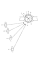
FIG. 1 is a schematic diagram showing a
図1に示すように、GPS付き腕時計1は、文字板2および指針3からなる時刻表示部を備える。文字板2の一部には開口が形成され、LCD表示パネル等からなるディスプレイ4が組み込まれている。
指針3は、秒針、分針、時針等を備えて構成され、後述するステップモータおよび歯車列を含む駆動機構を介して駆動される。
ディスプレイ4はLCD表示パネル等で構成され、緯度、経度や都市名等の位置情報を表示する他、メッセージ情報を表示する。
As shown in FIG. 1, the
The
The display 4 is composed of an LCD display panel and the like, and displays message information as well as position information such as latitude, longitude, and city name.
そして、GPS付き腕時計1は、地球の上空を所定の軌道で周回している複数のGPS衛星5からの衛星信号を受信して衛星時刻情報を取得し、内部時刻情報を修正できるように構成されている。
なお、GPS衛星5は、本発明における位置情報衛星の一例であり、地球の上空に複数存在している。現在は約30個のGPS衛星5が周回している。
また、GPS付き腕時計1には、外部操作用のリュウズ6、ボタン7,8が設けられている。
The
The GPS satellite 5 is an example of the position information satellite in the present invention, and a plurality of GPS satellites 5 exist above the earth. Currently, about 30 GPS satellites 5 orbit.
Further, the
[GPS付き腕時計の内部構成]
次に、GPS付き腕時計1の内部構成について説明する。
図2および図3に示すように、GPS付き腕時計1は、指針3を駆動するムーブメント64と、ムーブメント64を収容するケース60とを備えている
[Internal configuration of GPS wristwatch]
Next, the internal configuration of the
As shown in FIGS. 2 and 3, the
ケース60は、リング状の外装ケース17と、この外装ケース17の一方の開口(図2下側)を塞ぐ裏蓋26とを備えている。
外装ケース17および裏蓋26には、BS(真鍮)、SUS(ステンレス鋼)、チタン合金などの金属材料が利用される。裏蓋26は外装ケース17の開口に対してねじ構造により接続される。これにより、ケース60内には、外装ケース17の他方の開口(図2上側)に開口面61を有するキャビティ62が形成され、このキャビティ62にムーブメント64が収容される。
The
A metal material such as BS (brass), SUS (stainless steel), or titanium alloy is used for the
ムーブメント64は、前述した指針3による時刻表示を行うとともにGPS衛星からの信号受信を行うためのものであり、時刻表示およびGPS機能を処理する回路素子(ICなど)が実装された回路基板25、指針3を駆動するステップモータおよび歯車列を含む駆動機構19、これらに電力を供給する電池24を備えている。
回路基板25に実装された回路素子としては、GPS衛星から受信した信号を処理する受信部18、駆動機構19の制御を行う制御部20が含まれている。電池24はリチウムイオン電池などの二次電池となっている。
The
The circuit elements mounted on the
GPS付き腕時計1は、キャビティ62の開口面61には前述した文字板2が配置されている。
文字板2は、BS(真鍮)、SUS(ステンレス鋼)、チタン合金などの金属材料で構成されている。文字板2の表面には、外観性を向上するために、塗装やメッキ、スパッタリング等による表面処理が施されている。
前述した指針3は文字板2の表面側(図2上側)に配置され、ムーブメント64は文字板2の背面側(図2下側)に配置される。ムーブメント64においては、文字板2側から裏蓋26側にかけて駆動機構19、回路基板25、電池24の順で層状に配置される。回路基板25に実装された回路素子のうち、受信部18は回路基板25の文字板2に近い側の表面に配置され、制御部20は回路基板25の裏蓋26に近い側の表面に配置されている。
In the
The
The above-mentioned
GPS付き腕時計1は、文字板2の外周に沿ってGPSアンテナ11を備えている。
GPSアンテナ11は、前述したGPS衛星5からの信号を受信するものであり、文字板2の表面側に配置され、文字板2をグランド板として兼用するとともに、文字板2の外周に沿ってその内側を円弧状に延びる平面略C字形状とされている(図3参照)。
このGPS付き腕時計1の詳細については後述する。
The
The
Details of the
GPS付き腕時計1は、GPSアンテナ11を収容するリング部材としてのダイヤルリング110を備えている。
ダイヤルリング110は、外周径が文字板2に一致したリング状に形成され、外周にGPSアンテナ11を収容する凹みを有する。ダイヤルリング110は、内周が文字板2へと向かう傾斜面(円錐面)とされ、この傾斜面には60分割で指示目盛が印刷されている。
The
The
ダイヤルリング110の外周にはベゼル16が配置され、ベゼル16の内側には文字板2の表面側および指針3を覆うカバーガラス160が配置されている。
ベゼル16は、外周が外装ケース17の外周に連続するリング状に形成され、互いの対向面に形成された凹凸による嵌め合わせ構造あるいは両面粘着テープや接着剤等の手段によりケース60の外装ケース17に接続されている。ベゼル16は、カバーガラス160を保持するとともに、ダイヤルリング110を文字板2側へ押しつけて保持している。
以上により、カバーガラス160がムーブメント64の表面側を覆うように配置され、カバーガラス160とムーブメント64との間にグランド板である文字板2が配置され、この文字板2とカバーガラス160との間に指針3およびGPSアンテナ11が配置されている。
A
The
As described above, the
GPS付き腕時計1において、ケース60の外装ケース17および裏蓋26は、それぞれ質感の優れた金属材料で形成され、その表面には適宜な表面仕上げが施されている。
ダイヤルリング110およびベゼル16は合成樹脂あるいはセラミックス等の非導電性材料で形成され、カバーガラス160も非導電性のガラス質材料で形成されている。これらの各要素も質感を考慮した表面仕上げが施されている。
このような材質とすることで、文字板2よりも表面側(図2上側)にあるダイヤルリング110,ベゼル16、カバーガラス160は全て非導電性材料となり、これらが文字板2の表面側外周に設置されたGPSアンテナ11に対して電磁気的な遮蔽物として影響することがない。
In the
The
By using such a material, the
[GPSアンテナの詳細]
GPSアンテナ11は、いわゆる逆F型の給電を行うとともに誘電体による波長短縮を図った逆F型誘電体アンテナである。
図4に示すように、GPSアンテナ11は、矩形断面形状を有する円弧状の誘電体基材113を備え、その表面側にはアンテナ電極114が形成されている。
誘電体基材113に用いられる誘電体材料としては、高いアンテナ性能を重視する場合には高誘電率の誘電体セラミックスを用いることが望ましく、コストダウンを重視する場合には合成樹脂材料を用いることができる。
誘電体基材113は、前述した導電体材料の特性を考慮したうえで、使用する電波に応じた所定のアンテナ長が得られる長さとされている。
[Details of GPS antenna]
The
As shown in FIG. 4, the
As a dielectric material used for the
The
アンテナ電極114は、銅などの導電性の金属板を折り曲げて誘電体基材113の表面に貼り付けて形成される。なお、誘電体基材113の表面にパターン形成してもよい。
アンテナ電極114の一端側は、誘電体基材113の端面から背面側へと回り込み、誘電体基材113の底面(文字板2に当接される面)まで延長され、この部分により接地部115が形成されている。
アンテナ電極114の中間部には、誘電体基材113の側面を経由して底面まで延びる分岐部分が形成され、この部分により給電部116が形成されている。
接地部115および給電部116はアンテナ電極114と同材質とされる。
The
One end side of the
A branch portion that extends to the bottom surface via the side surface of the
The
接地部115の先端には接地側固定部117が形成され、給電部116の先端にはねじ孔を有する給電側固定部118が接続されている。
接地側固定部117は、接地部115を更に延長したうえで、誘電体基材113とは反対側に折曲されている。接地側固定部117は、表裏を貫通する固定用の挿通孔が形成されているとともに、底面が誘電体基材113の底面と同一面に形成されている。
給電側固定部118は、給電部116の下端に接続された金属片により構成され、表裏を貫通する固定用の挿通孔が形成されているとともに、誘電体基材113の底面に沿って配置されている。
A grounding
The ground
The power supply
文字板2には、接地側固定部117の挿通孔に応じた位置にねじ孔121が形成され、給電側固定部118に対応した輪郭の切欠き122が形成されている。切欠き122からは給電端子123が露出されている。
給電端子123は、文字板2の背面側に配置され、回路基板25の信号端子に電気的に接続されているとともに、給電側固定部118の挿通孔に応じた位置にねじ孔124が形成されている。
A
The
GPSアンテナ11は、ねじ125,126により文字板2に固定される。
ねじ125は、接地側固定部117の挿通孔を通して、文字板2のねじ孔121に螺合される。ねじ126は、給電側固定部118の挿通孔を通して、給電端子123のねじ孔124に螺合される。このような固定により、給電側固定部118は文字板2の切欠き122内に収容され、接地側固定部117ないし誘電体基材113の底面が文字板2の表面に密着される。
The
The
GPSアンテナ11が固定された状態では、接地側固定部117が文字板2に導通されるとともに、給電側固定部118は給電端子123と導通される。但し、給電側固定部118と文字板2とは絶縁状態に維持される。
これにより、GPSアンテナ11の接地部115は、文字板2を経て回路基板25の接地端子に接続される。また、GPSアンテナ11の給電部116は、給電端子123を経て回路基板25の信号端子に接続される。
なお、給電側固定部118と文字板2との絶縁を維持するためには、切欠き122を給電側固定部118の外周形状より大きく形成して互いに隙間を維持するとともに、給電端子123と文字板2の背面側との隙間を適切に維持するか、あるいは絶縁材を挟み込む等の処置を考慮すべきである。
In a state where the
Thereby, the
In order to maintain insulation between the power supply
図2に戻って、GPSアンテナ11と回路基板25との接続には、文字板2を貫通して回路基板25に至る接続部材25C,25Dが用いられる。
回路基板25において、GPS衛星からの受信信号を処理する受信部18は回路基板25の文字板2側の表面に実装され、かつGPSアンテナ11と距離が近くなる領域に配置されている。
Returning to FIG. 2,
In the
GPSアンテナ11は、文字板2の外周に沿った領域のうち、文字板2の6時から12時の角度範囲に配置されている(図3参照)。
このような配置により、腕時計1をユーザが左手首に装着した場合、歩行時等にGPSアンテナ11が上空に向いた状態に維持され、上空の位置情報衛星に対して受信状況を良好にすることができる。
また、このような配置とした場合、前述した外部操作用のリュウズ6あるいはボタン7,8等との干渉を避けることができる。
The
With such an arrangement, when the user wears the
In addition, with such an arrangement, it is possible to avoid interference with the above-described
GPSアンテナ11は、基本的に逆F型アンテナの動作となるので、アンテナ電極114のエレメント長は送受信信号の1/4波長が必要である。GPS衛星からの信号受信では周波数1575.42MHzであるため、誘電体がない状態ではエレメント長48mmが必要となる。しかし、本実施形態のGPSアンテナ11では、誘電体基材113として誘電率3程度の誘電体セラミック材料を用いることで、エレメント長28mmで十分な機能が得られる。
Since the
本実施形態において、文字板2はグランド板を兼ねるものであり、GPSアンテナ11のグランドプレーンとしての機能を有する。
一般に、アンテナのグランドプレーンは、そのサイズがなるべく大きいことが望ましく、グランドプレーンが矩形であれば一辺のサイズが、円形であれば外径(外周の直径)のサイズが、それぞれアンテナで送受信する信号の1/4波長以上であることが望ましい。
図5には、アンテナとグランドプレーン面積との関係を示すグラフが示されている。このグラフにおいて、縦軸はアンテナに得られる信号の利得、横軸はアンテナで送受信する信号の1/4波長を1とした時のサイズの相対値を示す。
本実施形態において、グランド板としての文字板2は、GPS衛星からの信号受信に適応するために外径48mm以上とすることが好ましい。但し、腕時計として利用される文字板2は外径35mm程度であり、必要な48mmを確保できない。この不足分を補うために、本実施形態では次のような構成が採用されている。
In the present embodiment, the
In general, it is desirable that the size of the antenna ground plane be as large as possible. If the ground plane is rectangular, the size of one side is the signal that is transmitted and received by the antenna. It is desirable that the wavelength is ¼ wavelength or more.
FIG. 5 shows a graph showing the relationship between the antenna and the ground plane area. In this graph, the vertical axis represents the gain of the signal obtained by the antenna, and the horizontal axis represents the relative value of the size when the quarter wavelength of the signal transmitted and received by the antenna is 1.
In this embodiment, it is preferable that the
本実施形態において、回路基板25は多層基板とされ、その一層にはグランド層25Bが形成されている。グランド層25Bは、回路基板25の他の層を連結するスルーホール等の部分は除去されて絶縁されつつ、なるべく大面積が得られる適宜な形状に形成されている。グランド層25Bは、回路基板25の接地端子に接続され、前述した接続部材25Cを介して文字板2に導通される。
ムーブメント64の裏蓋26に対向する側には、裏蓋26に圧接する接触端子65が形成されている。この接触端子65は、図示しない配線を介して前述した接続部材25Cに導通されており、これにより裏蓋26および外装ケース17に至る金属製のケース60が文字板2と導通される。
In the present embodiment, the
A
これらにより、文字板2の全体、回路基板25のグランド層25B、ケース60がGPSアンテナ11のグランドプレーンとして機能するように構成される。
なお、これらの導通部分、特に接触端子65の裏蓋26に接触する部分などには十分な接点の接触圧を確保するなど、高周波的に確実な接触(導通)が得られるように注意することが望ましい。
Thus, the
Care should be taken to ensure high-frequency reliable contact (conduction), such as securing sufficient contact pressure for these conductive parts, particularly the part that contacts the
なお、ディスプレイ4として文字板2の背面側に沿ってLCD表示パネル等が設置されるが、このLCD表示パネルはノイズの影響を遮断するためにシールド板で覆われる。この際、文字板2がグランド板を兼ねることで、ディスプレイ4の周囲についてもシールド効果が得られる。
また、駆動機構19のステップモータもノイズ源となりうるが、駆動機構19はGPSアンテナ11に対して文字板2の反対側なので、文字板2によってシールドされ、GPSアンテナ11への影響は抑止される。
An LCD display panel or the like is installed along the back side of the
The step motor of the
さらに、裏蓋26および外装ケース17を含むケース60が金属製なので、装着するユーザの腕によるGPSアンテナ11への影響を回避できる。つまり、ケース60がプラスチックケースだと、近傍にある腕の影響を受けて装着時と非装着時でアンテナの共振周波数が変動し、性能差が出て好ましくない。しかし、ケース60が金属製なので、そのシールド効果により腕の影響を回避でき、本実施形態では装着時と非装着時とのアンテナ特性差が殆どなく、安定した受信性能が得られる。
Furthermore, since the
[GPS付き腕時計の回路構成]
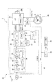
次に、GPS付き腕時計1の回路構成に関して説明する。図6に示すように、GPS付き腕時計1は、時刻表示装置45、GPS装置40、時刻修正装置44を備え、コンピュータとしての機能も発揮する構成となっている。なお、図6に示すように、GPS装置40、時刻修正装置44は一部の構成が重複している。
[Circuit configuration of GPS wristwatch]
Next, the circuit configuration of the
GPS装置40は、GPSアンテナ11、フィルタ(SAW)31、受信部18を備える。フィルタ(SAW)31は、バンドパスフィルタであり、1.5GHzの衛星信号を抜き出すものとなっている。従って、GPS装置40により、本発明の受信部が構成されている。
The
受信部18は、フィルタで抜き出された衛星信号を処理するものであり、RF部(Radio Frequency:無線周波数)27とベースバンド部30を備える。
RF部27は、PLL回路34、IFフィルタ35、VCO(Voltage Controlled Oscillator)41、ADC(A/D変換器)42、ミキサ46、LNA(Low Noise Amplifier)47、IFアンプ48等を備えている。
The receiving
The
そして、フィルタ31で抜き出された衛星信号は、LNA47で増幅された後、ミキサ46でVCO41の信号とミキシングされ、IF(Intermediate Frequency:中間周波数)にダウンコンバートされる。
ミキサ46でミキシングされたIFは、IFアンプ48、IFフィルタ35を通り、ADC(A/D変換器)42でデジタル信号に変換される。
The satellite signal extracted by the
The IF mixed by the
ベースバンド部30は、DSP(Digital Signal Processor)39、CPU(Central Processing Unit)36、SRAM(Static Random Access Memory)37、RTC(リアルタイムクロック)38を備える。また、ベースバンド部30には、温度補償回路付き水晶発振回路(TCXO)32やフラッシュメモリ33等も接続されている。
そして、ベースバンド部30は、RF部27のADC42からデジタル信号が入力され、制御信号に基づき、衛星信号の演算を行い、衛星時刻情報や測位情報を取得できるようになっている。
The
The
なお、PLL回路34用のクロック信号は、温度補償回路付き水晶発振回路(TCXO)32から生成されるようになっている。
また、RTC38は、衛星信号を処理するために、受信機側の時刻情報を生成するものである。このRTC38は、TCXO32から出力される基準クロックでカウントアップされるようになっている。
The clock signal for the
The
時刻修正装置44は、前記受信部18と、制御部20と、駆動回路43とを備えている。この時刻修正装置44で本発明の時刻情報修正部が構成されている。
制御部20は、記憶部20Aを備えるとともに、GPS装置40や、指針3、ディスプレイ4の駆動を制御するものである。すなわち、制御部20は、制御信号を受信部18に送り、GPS装置40の受信動作を制御できるようになっている。
The
The
本実施形態のGPS付き腕時計1は、上述のようなGPS装置40を備え、特に時刻修正装置44を備えていることで、GPS衛星からの受信信号に基づいて時刻表示を自動的に修正することができる。
The
以上のような本実施形態によれば、以下のような効果が得られる。
GPS付き腕時計1の表面側に、カバーガラス160で覆われた文字板2をグランド板として機能するように構成した。このため、GPSアンテナ11においては、グランド板として文字板2に相当する十分な面積を確保することができ、良好なアンテナ性能を確保できる。
グランド板として、文字板2に導通するように、回路基板25のグランド層25Bを形成するとともに、ケース60をも導通させるようにした。このため、GPSアンテナ11においては更に大きなグランドプレーンを確保することができ、良好なアンテナ性能を確保できる。
According to the present embodiment as described above, the following effects can be obtained.
On the surface side of the
As the ground plate, the
GPSアンテナ11は、文字板2の表面側に配置され、その周囲のダイヤルリング110、ベゼル16等を非導電性の材料とした。このため、ケース60を外観性の優れた金属材料にしても電磁遮蔽を受けることがなく、良好なアンテナ性能を確保できる。
GPSアンテナ11において、アンテナ電極114に沿った誘電体基材113を設けたため、アンテナを小型化しても十分なアンテナ性能を得ることができる。
The
In the
文字板2はグランド板としての導電性が得られればよいため、質感の高い金属製とすることができる。また、GPSアンテナ11は文字板2の外周に沿って配置するため、ダイヤルリング110で被覆しても文字板2の表示部分を隠すことがない。このため、GPS付き腕時計1質感を考慮した外観性の向上を図ることができる。
さらに、GPS付き腕時計1は、文字板2自体をグランド板として兼用するため、構造の簡略化を図ることができる。
Since the
Furthermore, since the
〔第2実施形態〕
図7には、本発明の第2実施形態が示されている。
本実施形態において、GPS付き腕時計1の各部構成は前述した第1実施形態と同様であり、簡略化のため共通の構成については説明を省略する。
本実施形態においては、文字板2がグランド板として兼用されることに加え、文字板2の背面側に誘電性面材2Aが貼り合わせられている。
このような誘電性面材2Aを伴う文字板2を用いた場合、誘電性面材2Aとして誘電率2程度の誘電体を用いることで、文字板2の外径が35mm程度であってもGPS信号の受信に十分なアンテナ性能を確保できる。
[Second Embodiment]
FIG. 7 shows a second embodiment of the present invention.
In this embodiment, the configuration of each part of the
In the present embodiment, in addition to the
When the
このような本実施形態によれば、前述した第1実施形態と同様な効果に加えて、文字板2に沿って誘電体面材2Aを配置することで、グランドプレーンの有効面積を更に大きく確保することができ、良好なアンテナ性能を確保できる。
なお、このような誘電性面材2Aにより十分なアンテナ性能が確保できるのであれば、前述した第1実施形態で用いた接触端子65によるケース60への導通あるいは回路基板25のグランド層25Bは適宜省略してもよい。
According to this embodiment, in addition to the same effects as those of the first embodiment described above, by arranging the
If sufficient dielectric performance can be ensured by such a
〔第3実施形態〕
図8には、本発明の第3実施形態が示されている。
本実施形態において、GPS付き腕時計1の各部構成は前述した第1実施形態と同様であり、簡略化のため共通の構成については説明を省略する。
本実施形態においては、第1実施形態の文字板2に代えて、ケース60のキャビティ62の開口面61にグランド板としてのソーラパネル基板66が配置されている。
ソーラパネル基板66は、表面側にソーラパネル66Aが形成されるステンレス等の導電性基板である。ソーラパネル基板66は、回路基板25の接地端子に接続されることによりグランドプレーンとして機能する。
[Third Embodiment]
FIG. 8 shows a third embodiment of the present invention.
In this embodiment, the configuration of each part of the
In the present embodiment, a
The
ソーラパネル66Aの表面側には文字板2Bが張られている。
文字板2Bおよびソーラパネル66Aは、各々の外周径がダイヤルリング110の内周径に合わせて形成され、各々の外周はダイヤルリング110の内周に隙間なく密着され、ソーラパネル基板66が外部から視認されることはない。
文字板2Bは透光性を有する合成樹脂材料で形成され、ソーラパネル66Aへの入射光
の透過を妨げることがない。
A
The
The
このような本実施形態によれば、前述した第1実施形態と同様な効果に加えて、ソーラパネル66Aによる電力供給を行うGPS付き腕時計1においても、良好な外観性とアンテナ性能の両立が図れる。
According to this embodiment, in addition to the same effects as those of the first embodiment described above, the
〔他の実施形態〕
前述した各実施形態では、GPSアンテナ11を覆うリング部材としてダイヤルリング110を設けたが、これに限らず、リング部材は目盛のない部材であってもよく、内側面が傾斜面ではなく文字板2に対して垂直な面あるいは他の形状であるとしてもよい。また、リング部材は本発明に必須ではなく、例えばベゼル16の内周が内側に張り出してGPSアンテナ11を覆い隠せるようであれば、別体のリング部材は省略することができる。
[Other Embodiments]
In each of the embodiments described above, the
前述した各実施形態では、金属製の文字板2自体をグランド板として兼用した例、ソーラパネル用のソーラパネル基板66をグランド板として兼用した例について説明したが、他の機能部材と兼用でない専用の金属板を用い、これをケース60のキャビティ62の開口面61に配置するようにしてもよい。
グランド板の材料としては、金属製の板材に限らず、非金属材料からなる板材の表面に金属皮膜を形成したものであってもよい。また、連続した板材に限らず、複数の小片を連続させて平板状に形成したもの、概略形状が平板状とされた金属メッシュ材料などを用いてもよい。
In each of the embodiments described above, an example in which the
The material of the ground plate is not limited to a metal plate material, but may be a material in which a metal film is formed on the surface of a plate material made of a non-metallic material. Moreover, not only a continuous plate material, but also a metal plate material in which a plurality of small pieces are continuously formed and formed into a flat plate shape, or a substantially meshed flat plate shape may be used.
前記各実施形態では、グランド板としての文字板2あるいはソーラパネル基板66よりも表面側に配置される各部材(ベゼル16、カバーガラス160、ダイヤルリング110)は、GPSアンテナ11を除き合成樹脂材料やセラミックス材料などの非導電性材料として電磁遮蔽性を回避するようにしたが、全ての部分をこのような非導電性材料とすることは必須ではなく、これらの各要素の一部に金属材料が用いられることを妨げるものではない。但し、金属材料の増加に伴ってアンテナへの電磁遮蔽が増すため、アンテナ性能が確保できるように留意するべきである。
なお、指針3は面積が小さいことから、金属製であっても支承ないが、前述した非導電性材料であればアンテナへの影響を回避できて好ましい。
In each of the embodiments, each member (
Although the
前記各実施形態では、GPSアンテナ11を、文字板2の6時方向から9時方向を経て12時方向の角度範囲に配置したが、例えば6時から9時の範囲にわたって配置してもよく、アンテナ長を確保したい場合などに好適である。使用する電波の周波数が高くアンテナ長を短くできる場合には7時から9時の角度範囲に短縮してもよい。
更に、右腕装着時の通信状況改善のため文字板2の12時方向から3時方向を経て6時方向の角度範囲にGPSアンテナ11を配置した態様としてもよい。
In each of the above embodiments, the
Furthermore, it is good also as an aspect which has arrange | positioned the
前記各実施形態では、GPSアンテナ11として誘電体を伴う逆F型アンテナを用いたが、これと同等以下の大きさで同等以上の通信性能が得られる他の構成(例えばパッチアンテナ、ループアンテナ、チップアンテナなど)があれば、これを採用してもよい。
その他、ケース60を構成する外装ケース17、裏蓋26、あるいはベゼル16、カバーガラス160の構成、各々の形状、材質など、あるいは文字板2,2Bの表面意匠などは実施にあたって適宜変更することができるものである。
In each of the above embodiments, an inverted-F antenna with a dielectric is used as the
In addition, the configuration of the
1…GPS付腕時計(無線機能付腕時計)、2,2B…文字板(グランド板)、2A…誘電性面材、3…指針、11…GPSアンテナ、113…誘電体基材、114…アンテナ電極、16…ベゼル、25…回路基板、25B…グランド層、160…カバーガラス、110…ダイヤルリング(リング部材)、60…ケース、64…ムーブメント、66…ソーラパネル基板(グランド板)
DESCRIPTION OF
Claims (10)
前記アンテナは前記リング部材内に収容されている
ことを特徴とする無線機能付腕時計。 A movement for displaying a pointer, a case for housing the movement, a cover glass covering the surface side of the movement, a ground plate disposed between the cover glass and the movement, the ground plate and the cover glass And an antenna arranged along the outer periphery of the ground plate between and a non-conductive ring member,
The wireless function wristwatch, wherein the antenna is accommodated in the ring member .
前記グランド板は、導電性の文字板である
ことを特徴とする無線機能付腕時計。 The wireless function wristwatch according to claim 1,
The wristwatch with a wireless function, wherein the ground plate is a conductive dial.
前記グランド板は、ソーラパネルの導電性基板である
ことを特徴とする無線機能付腕時計。 The wireless function wristwatch according to claim 1,
The wristwatch with a wireless function, wherein the ground plate is a conductive substrate of a solar panel.
前記グランド板の前記ムーブメント側に配置された誘電性面材を備えた
ことを特徴とする無線機能付腕時計。 In the wristwatch with a wireless function according to any one of claims 1 to 3,
A wristwatch with a wireless function, comprising a dielectric face material disposed on the movement side of the ground plate.
前記ムーブメント内に配置されかつグランド層を含む多層回路基板を備え、
前記グランド板は、前記グランド層と電気的に導通された
ことを特徴とする無線機能付腕時計。 In the wristwatch with a wireless function according to any one of claims 1 to 4,
A multilayer circuit board disposed in the movement and including a ground layer;
The wristwatch with a wireless function, wherein the ground plate is electrically connected to the ground layer.
前記グランド板は、前記ケースと電気的に導通された
ことを特徴とする無線機能付腕時計。 In the wristwatch with a wireless function according to any one of claims 1 to 5,
The wristwatch with a wireless function, wherein the ground plate is electrically connected to the case.
前記カバーガラスの周囲に配置された非導電性のベゼルを備えた
ことを特徴とする無線機能付腕時計。 In the wristwatch with a wireless function according to any one of claims 1 to 6,
A wristwatch with a wireless function, comprising a non-conductive bezel disposed around the cover glass.
前記アンテナは、少なくとも指針表示における6時方向から9時方向までの領域に配置された
ことを特徴とする無線機能付腕時計。 In the wristwatch with a wireless function according to any one of claims 1 to 7,
A wristwatch with a wireless function, wherein the antenna is disposed at least in a region from 6 o'clock direction to 9 o'clock direction on a pointer display.
前記アンテナは、前記グランド板の外周に沿って配置された誘電性基材と、前記誘電性基材の表面に形成されたアンテナ電極とを備えた
ことを特徴とする無線機能付腕時計。 In the wristwatch with a wireless function according to any one of claims 1 to 8,
The wireless function wristwatch, wherein the antenna includes a dielectric base disposed along an outer periphery of the ground plate and an antenna electrode formed on a surface of the dielectric base.
前記アンテナは、位置情報衛星からの電波を受信するものである
ことを特徴とする無線機能付腕時計。 The wireless function wristwatch according to any one of claims 1 to 9,
The wristwatch with a wireless function, wherein the antenna receives radio waves from a position information satellite.
Priority Applications (1)
| Application Number | Priority Date | Filing Date | Title |
|---|---|---|---|
| JP2008007766A JP5082870B2 (en) | 2008-01-17 | 2008-01-17 | Wristwatch with wireless function |
Applications Claiming Priority (1)
| Application Number | Priority Date | Filing Date | Title |
|---|---|---|---|
| JP2008007766A JP5082870B2 (en) | 2008-01-17 | 2008-01-17 | Wristwatch with wireless function |
Related Child Applications (1)
| Application Number | Title | Priority Date | Filing Date |
|---|---|---|---|
| JP2012195323A Division JP5344072B2 (en) | 2012-09-05 | 2012-09-05 | Wristwatch with wireless function |
Publications (3)
| Publication Number | Publication Date |
|---|---|
| JP2009168656A JP2009168656A (en) | 2009-07-30 |
| JP2009168656A5 JP2009168656A5 (en) | 2011-02-24 |
| JP5082870B2 true JP5082870B2 (en) | 2012-11-28 |
Family
ID=40969989
Family Applications (1)
| Application Number | Title | Priority Date | Filing Date |
|---|---|---|---|
| JP2008007766A Active JP5082870B2 (en) | 2008-01-17 | 2008-01-17 | Wristwatch with wireless function |
Country Status (1)
| Country | Link |
|---|---|
| JP (1) | JP5082870B2 (en) |
Cited By (2)
| Publication number | Priority date | Publication date | Assignee | Title |
|---|---|---|---|---|
| WO2018004183A1 (en) * | 2016-06-28 | 2018-01-04 | Lg Electronics Inc. | Solar cell module, method for manufacturing solar cell module, method for manufacturing electronic device having solar cell module |
| KR101856965B1 (en) * | 2016-07-07 | 2018-05-11 | 엘지전자 주식회사 | Sensor module having solar cell |
Families Citing this family (23)
| Publication number | Priority date | Publication date | Assignee | Title |
|---|---|---|---|---|
| JP5493527B2 (en) | 2009-07-14 | 2014-05-14 | セイコーエプソン株式会社 | Clock with wireless function |
| JP5610041B2 (en) * | 2009-09-01 | 2014-10-22 | セイコーエプソン株式会社 | Antenna built-in clock |
| JP2011097431A (en) * | 2009-10-30 | 2011-05-12 | Seiko Epson Corp | Arm-mounted electronic apparatus |
| JP5546510B2 (en) * | 2010-08-30 | 2014-07-09 | 学校法人智香寺学園 | Small electronic device |
| JP5866860B2 (en) * | 2011-01-05 | 2016-02-24 | セイコーエプソン株式会社 | Clock with wireless function |
| JP2012163335A (en) * | 2011-02-03 | 2012-08-30 | Seiko Epson Corp | Electronic timepiece with built-in antenna |
| JP5712695B2 (en) * | 2011-03-11 | 2015-05-07 | セイコーエプソン株式会社 | Electronic clock with built-in antenna |
| JP5831049B2 (en) * | 2011-08-30 | 2015-12-09 | セイコーエプソン株式会社 | Electronic clock with built-in antenna |
| JP2013050349A (en) * | 2011-08-30 | 2013-03-14 | Seiko Epson Corp | Electronic timepiece with built-in antenna |
| JP5994523B2 (en) * | 2012-09-24 | 2016-09-21 | セイコーエプソン株式会社 | Electronic clock with built-in antenna |
| JP6036084B2 (en) * | 2012-09-24 | 2016-11-30 | セイコーエプソン株式会社 | Electronic clock with built-in antenna |
| JP6028490B2 (en) * | 2012-09-24 | 2016-11-16 | セイコーエプソン株式会社 | Electronic clock with built-in antenna |
| JP5994522B2 (en) * | 2012-09-24 | 2016-09-21 | セイコーエプソン株式会社 | Electronic clock with built-in antenna |
| JP6031913B2 (en) * | 2012-09-24 | 2016-11-24 | セイコーエプソン株式会社 | Electronic clock with built-in antenna |
| CN103676631B (en) * | 2012-09-24 | 2016-08-10 | 精工爱普生株式会社 | Electronic timepiece with internal antenna |
| JP6179123B2 (en) | 2013-02-21 | 2017-08-16 | セイコーエプソン株式会社 | Electronic clock with built-in antenna |
| JP6331430B2 (en) | 2014-01-31 | 2018-05-30 | セイコーエプソン株式会社 | Electronic clock |
| JP5796670B2 (en) * | 2014-08-20 | 2015-10-21 | セイコーエプソン株式会社 | Arm-mounted electronic device |
| JP6459593B2 (en) | 2015-02-13 | 2019-01-30 | セイコーエプソン株式会社 | Antenna device and electronic timepiece |
| JP6610245B2 (en) * | 2015-12-25 | 2019-11-27 | セイコーエプソン株式会社 | Electronics |
| JP6848820B2 (en) | 2017-11-07 | 2021-03-24 | カシオ計算機株式会社 | Electronic clock |
| JP2019086414A (en) | 2017-11-07 | 2019-06-06 | カシオ計算機株式会社 | Electronic timepiece |
| US11569572B2 (en) * | 2020-10-28 | 2023-01-31 | Garmin Switzerland Gmbh | Watch with integrated antenna configuration |
Family Cites Families (4)
| Publication number | Priority date | Publication date | Assignee | Title |
|---|---|---|---|---|
| JPS55103593U (en) * | 1979-01-16 | 1980-07-19 | ||
| JPH10206561A (en) * | 1997-01-22 | 1998-08-07 | Citizen Watch Co Ltd | Electronic timepiece |
| JP2005164273A (en) * | 2003-11-28 | 2005-06-23 | Seiko Instruments Inc | Radio controlled watch |
| JP4551678B2 (en) * | 2004-03-24 | 2010-09-29 | シチズンホールディングス株式会社 | Cell phone clock |
-
2008
- 2008-01-17 JP JP2008007766A patent/JP5082870B2/en active Active
Cited By (2)
| Publication number | Priority date | Publication date | Assignee | Title |
|---|---|---|---|---|
| WO2018004183A1 (en) * | 2016-06-28 | 2018-01-04 | Lg Electronics Inc. | Solar cell module, method for manufacturing solar cell module, method for manufacturing electronic device having solar cell module |
| KR101856965B1 (en) * | 2016-07-07 | 2018-05-11 | 엘지전자 주식회사 | Sensor module having solar cell |
Also Published As
| Publication number | Publication date |
|---|---|
| JP2009168656A (en) | 2009-07-30 |
Similar Documents
| Publication | Publication Date | Title |
|---|---|---|
| JP5082870B2 (en) | Wristwatch with wireless function | |
| JP5493527B2 (en) | Clock with wireless function | |
| JP6179123B2 (en) | Electronic clock with built-in antenna | |
| EP1642176B1 (en) | Ground connection of a printed circuit board placed in a wristwatch type electronic device | |
| JP5866860B2 (en) | Clock with wireless function | |
| US9130272B2 (en) | Electronic device that is worn on the wrist | |
| JP6331430B2 (en) | Electronic clock | |
| JP2014062866A (en) | Built-in antenna electronic clock | |
| JP7003506B2 (en) | Electronic clock | |
| JP5741734B2 (en) | Clock with wireless function | |
| JP6996372B2 (en) | Electronic clock | |
| JP5796670B2 (en) | Arm-mounted electronic device | |
| JP5344072B2 (en) | Wristwatch with wireless function | |
| JP6232729B2 (en) | Electronic clock with built-in antenna | |
| JP2018169383A (en) | Electronic clock | |
| JP5896060B2 (en) | Electronic clock with built-in antenna | |
| JP5998648B2 (en) | Electronic clock | |
| JP2023091617A (en) | Electronic watch | |
| JP2013050323A (en) | Electronic watch | |
| JP2022023316A (en) | Electronic timepiece |
Legal Events
| Date | Code | Title | Description |
|---|---|---|---|
| A521 | Written amendment |
Free format text: JAPANESE INTERMEDIATE CODE: A523 Effective date: 20110112 |
|
| A621 | Written request for application examination |
Free format text: JAPANESE INTERMEDIATE CODE: A621 Effective date: 20110112 |
|
| A977 | Report on retrieval |
Free format text: JAPANESE INTERMEDIATE CODE: A971007 Effective date: 20120802 |
|
| TRDD | Decision of grant or rejection written | ||
| A01 | Written decision to grant a patent or to grant a registration (utility model) |
Free format text: JAPANESE INTERMEDIATE CODE: A01 Effective date: 20120807 |
|
| A01 | Written decision to grant a patent or to grant a registration (utility model) |
Free format text: JAPANESE INTERMEDIATE CODE: A01 |
|
| A61 | First payment of annual fees (during grant procedure) |
Free format text: JAPANESE INTERMEDIATE CODE: A61 Effective date: 20120820 |
|
| R150 | Certificate of patent or registration of utility model |
Ref document number: 5082870 Country of ref document: JP Free format text: JAPANESE INTERMEDIATE CODE: R150 Free format text: JAPANESE INTERMEDIATE CODE: R150 |
|
| FPAY | Renewal fee payment (event date is renewal date of database) |
Free format text: PAYMENT UNTIL: 20150914 Year of fee payment: 3 |
|
| S531 | Written request for registration of change of domicile |
Free format text: JAPANESE INTERMEDIATE CODE: R313531 |
|
| R350 | Written notification of registration of transfer |
Free format text: JAPANESE INTERMEDIATE CODE: R350 |