JP5063883B2 - Wireless communication apparatus, transmission method, transmission apparatus, data transmission system, and data transmission method - Google Patents
Wireless communication apparatus, transmission method, transmission apparatus, data transmission system, and data transmission method Download PDFInfo
- Publication number
- JP5063883B2 JP5063883B2 JP2005285508A JP2005285508A JP5063883B2 JP 5063883 B2 JP5063883 B2 JP 5063883B2 JP 2005285508 A JP2005285508 A JP 2005285508A JP 2005285508 A JP2005285508 A JP 2005285508A JP 5063883 B2 JP5063883 B2 JP 5063883B2
- Authority
- JP
- Japan
- Prior art keywords
- format
- packet
- cqi
- unit
- reception quality
- Prior art date
- Legal status (The legal status is an assumption and is not a legal conclusion. Google has not performed a legal analysis and makes no representation as to the accuracy of the status listed.)
- Expired - Fee Related
Links
- 230000005540 biological transmission Effects 0.000 title claims description 153
- 238000004891 communication Methods 0.000 title claims description 117
- 238000000034 method Methods 0.000 title claims description 23
- 238000005259 measurement Methods 0.000 claims description 20
- 101000741965 Homo sapiens Inactive tyrosine-protein kinase PRAG1 Proteins 0.000 claims description 14
- 102100038659 Inactive tyrosine-protein kinase PRAG1 Human genes 0.000 claims description 14
- 230000006866 deterioration Effects 0.000 claims 2
- 238000010586 diagram Methods 0.000 description 28
- 230000003044 adaptive effect Effects 0.000 description 19
- 238000011156 evaluation Methods 0.000 description 9
- 238000012545 processing Methods 0.000 description 8
- 239000000872 buffer Substances 0.000 description 7
- 238000012937 correction Methods 0.000 description 6
- 230000000694 effects Effects 0.000 description 6
- 238000003780 insertion Methods 0.000 description 3
- 230000037431 insertion Effects 0.000 description 3
- 238000012935 Averaging Methods 0.000 description 2
- 230000007423 decrease Effects 0.000 description 2
- 238000011088 calibration curve Methods 0.000 description 1
- 230000001413 cellular effect Effects 0.000 description 1
- 125000004122 cyclic group Chemical group 0.000 description 1
- 239000000284 extract Substances 0.000 description 1
- 238000005562 fading Methods 0.000 description 1
- 238000010295 mobile communication Methods 0.000 description 1
- 230000000737 periodic effect Effects 0.000 description 1
- 230000001131 transforming effect Effects 0.000 description 1
- 238000011144 upstream manufacturing Methods 0.000 description 1
Images


Classifications
-
- H—ELECTRICITY
- H04—ELECTRIC COMMUNICATION TECHNIQUE
- H04L—TRANSMISSION OF DIGITAL INFORMATION, e.g. TELEGRAPHIC COMMUNICATION
- H04L1/00—Arrangements for detecting or preventing errors in the information received
- H04L1/12—Arrangements for detecting or preventing errors in the information received by using return channel
- H04L1/16—Arrangements for detecting or preventing errors in the information received by using return channel in which the return channel carries supervisory signals, e.g. repetition request signals
- H04L1/1607—Details of the supervisory signal
- H04L1/1671—Details of the supervisory signal the supervisory signal being transmitted together with control information
-
- H—ELECTRICITY
- H04—ELECTRIC COMMUNICATION TECHNIQUE
- H04W—WIRELESS COMMUNICATION NETWORKS
- H04W24/00—Supervisory, monitoring or testing arrangements
- H04W24/10—Scheduling measurement reports ; Arrangements for measurement reports
-
- H—ELECTRICITY
- H04—ELECTRIC COMMUNICATION TECHNIQUE
- H04L—TRANSMISSION OF DIGITAL INFORMATION, e.g. TELEGRAPHIC COMMUNICATION
- H04L1/00—Arrangements for detecting or preventing errors in the information received
- H04L1/0001—Systems modifying transmission characteristics according to link quality, e.g. power backoff
- H04L1/0023—Systems modifying transmission characteristics according to link quality, e.g. power backoff characterised by the signalling
- H04L1/0026—Transmission of channel quality indication
-
- H—ELECTRICITY
- H04—ELECTRIC COMMUNICATION TECHNIQUE
- H04L—TRANSMISSION OF DIGITAL INFORMATION, e.g. TELEGRAPHIC COMMUNICATION
- H04L1/00—Arrangements for detecting or preventing errors in the information received
- H04L1/0001—Systems modifying transmission characteristics according to link quality, e.g. power backoff
- H04L1/0023—Systems modifying transmission characteristics according to link quality, e.g. power backoff characterised by the signalling
- H04L1/0028—Formatting
- H04L1/003—Adaptive formatting arrangements particular to signalling, e.g. variable amount of bits
-
- H—ELECTRICITY
- H04—ELECTRIC COMMUNICATION TECHNIQUE
- H04L—TRANSMISSION OF DIGITAL INFORMATION, e.g. TELEGRAPHIC COMMUNICATION
- H04L1/00—Arrangements for detecting or preventing errors in the information received
- H04L1/20—Arrangements for detecting or preventing errors in the information received using signal quality detector
-
- H—ELECTRICITY
- H04—ELECTRIC COMMUNICATION TECHNIQUE
- H04L—TRANSMISSION OF DIGITAL INFORMATION, e.g. TELEGRAPHIC COMMUNICATION
- H04L1/00—Arrangements for detecting or preventing errors in the information received
- H04L1/0001—Systems modifying transmission characteristics according to link quality, e.g. power backoff
- H04L1/0002—Systems modifying transmission characteristics according to link quality, e.g. power backoff by adapting the transmission rate
- H04L1/0003—Systems modifying transmission characteristics according to link quality, e.g. power backoff by adapting the transmission rate by switching between different modulation schemes
Description
本発明はデータ伝送システムおよびデータ伝送方法に関し、特にデータチャネルを備えるパケットの送受信を行うデータ伝送システムおよびデータ伝送方法に関する。 The present invention relates to a data transmission system and a data transmission method, and more particularly to a data transmission system and a data transmission method for transmitting and receiving packets having a data channel.
一般的に、セルラー移動通信におけるパケット伝送では、データパケットの伝送効率を高めるために、適応変調、再送制御およびスケジューリング等の適応無線リンク制御が用いられている。これらの制御は、データチャネルと同時に送信される制御チャネルを用いて行われ、基地局は、下りリンク(基地局から移動局へのリンク)の制御チャネルによってデータチャネルで使用している無線リンクのパラメータを移動局に通知する。例えば、適応変調の場合、制御チャネルは、データチャネルの変調方式および符号化率の情報を伝送する。再送制御の場合は、制御チャネルは、データチャネルで伝送されるパケット番号や再送回数等の情報を伝送する。スケジューリングを行う場合は、パケットと同時に移動局(ユーザ)IDの情報を伝送する。 In general, in packet transmission in cellular mobile communication, adaptive radio link control such as adaptive modulation, retransmission control, and scheduling is used to increase the transmission efficiency of data packets. These controls are performed using a control channel transmitted simultaneously with the data channel, and the base station uses the control channel of the downlink (link from the base station to the mobile station) of the radio link used in the data channel. Notify the parameter to the mobile station. For example, in the case of adaptive modulation, the control channel transmits data channel modulation scheme and coding rate information. In the case of retransmission control, the control channel transmits information such as the packet number transmitted on the data channel and the number of retransmissions. When scheduling is performed, mobile station (user) ID information is transmitted simultaneously with the packet.
このような適応無線リンク制御は、時間・周波数・空間(アンテナまたは指向性ビーム)等の無線リソース単位で行われる。移動局は、下りリンクのパイロットチャネルを用いて、これらの無線リソース毎にCQI(Channel Quality Indicator)と呼ばれる伝送チャネルの品質を表すパラメータを測定し、その情報を上りリンク(移動局から基地局へのリンク)の制御チャネルを用いて基地局にフィードバックする(例えば、特許文献1参照)。この特許文献1では、周期的なCQIのフィードバックに加えて、NACK(Negative Acknowledgment)を返送する場合にCQIのフィードバックを行う方法が提案されている。なお、特許文献1では、ACK(Acknowledgement)を返送する場合にはCQIのフィードバックは行われない。
Such adaptive radio link control is performed in units of radio resources such as time, frequency, and space (antenna or directional beam). The mobile station uses a downlink pilot channel to measure a parameter indicating the quality of a transmission channel called CQI (Channel Quality Indicator) for each of these radio resources, and transmits the information to the uplink (from the mobile station to the base station). Feedback) to the base station using the control channel (see, for example, Patent Document 1). In
ところで、CQIには、通常、SIR(Signal-to-Interference power Ratio:信号対干渉比)が用いられる。SIRは、下りリンクのパイロットチャネルから求められるチャネル推定値を用いて以下のように計算する。 By the way, SIR (Signal-to-Interference power Ratio) is usually used for CQI. The SIR is calculated as follows using the channel estimation value obtained from the downlink pilot channel.
今、k番目のパイロットから求めたチャネル推定値をhkとすると、K個のパイロットシンボルを用いて、受信電力Sと干渉電力I、およびSIRは以下、式(1)〜式(4)のように求められる。 Now, assuming that the channel estimation value obtained from the k-th pilot is h k , the received power S, interference power I, and SIR are expressed by the following equations (1) to (4) using K pilot symbols. Asking.

![]()
![]()
![]()
![]()
![]()
![]()
次世代の無線通信システムでは、時間領域をパケットと呼ばれる無線リソース単位に分割し、パケット毎に、適応変調やスケジューリング等の制御を行う。また、次世代の無線通信システムでは、OFDMA(Orthogonal Frequency Division Multiple Access)と呼ばれるマルチキャリア伝送が用いられる。OFDMAでは、無線リソースを周波数(サブキャリア)の単位に分割し、周波数毎に、適応変調やスケジューリング等の制御を行う。また、次世代の無線通信システムでは、複数の送受信アンテナを用いて送信アンテナ毎に独立のデータ伝送を行う、MIMO(Multiple-Input Multiple-Output)と呼ばれる空間多重伝送が用いられる。この場合は、アンテナ毎に、適応変調やスケジューリング等の制御を行うことができる。 In the next-generation radio communication system, the time domain is divided into radio resource units called packets, and control such as adaptive modulation and scheduling is performed for each packet. In the next-generation radio communication system, multicarrier transmission called OFDMA (Orthogonal Frequency Division Multiple Access) is used. In OFDMA, radio resources are divided into frequency (subcarrier) units, and adaptive modulation, scheduling, and the like are controlled for each frequency. In the next-generation radio communication system, spatial multiplexing transmission called MIMO (Multiple-Input Multiple-Output) is used, in which independent transmission is performed for each transmission antenna using a plurality of transmission / reception antennas. In this case, control such as adaptive modulation and scheduling can be performed for each antenna.
これらの無線リソースの分割単位は、複数の組合せで用いられる。すなわち、無線リソースは、時間領域のパケットに分割されると同時に、OFDMAの場合は周波数領域でも分割され、さらにMIMOを用いる場合はアンテナ毎に分割することも可能である。このように、無線リソースの分割単位を細かくするほど、最適な制御が可能になる。また、複数の移動局(ユーザ)でスケジューリングを行う場合には、無線リソースの分割が細かいほど、高いユーザダイバーシチ利得が得られる。
このように、次世代の無線通信システムでは、無線リソース単位での適応無線リンク制御が行われるが、最適な制御を行い高いユーザダイバーシチ利得を得るためには、無線リソースを細かく分割する必要がある。 As described above, in the next-generation radio communication system, adaptive radio link control is performed in units of radio resources. However, in order to perform optimal control and obtain a high user diversity gain, it is necessary to divide radio resources finely. .
しかしながら、無線リソースの単位を細かくすると、測定すべきCQIの数が増え、フィードバックするCQIの情報量が増大してしまう。その結果、基地局へのフィードバックに使用する上りリンクへの負荷が増大してしまい、上りリンクの使用効率が低下するという問題があった。 However, if the unit of radio resources is made finer, the number of CQIs to be measured increases and the amount of CQI information to be fed back increases. As a result, there is a problem in that the load on the uplink used for feedback to the base station increases and the use efficiency of the uplink decreases.
本発明はこのような点に鑑みてなされたものであり、上りリンク(フィードバック回線)の負荷を軽減することができるデータ伝送システムおよびデータ伝送方法を提供することを目的とする。 The present invention has been made in view of these points, and an object of the present invention is to provide a data transmission system and a data transmission method capable of reducing the load on the uplink (feedback line).
上記問題を解決するために、受信品質情報に基づいて送信制御を実行する送信装置との間で無線通信を行う無線通信装置が提供される。無線通信装置は、前記無線通信についての通信品質に応じて、前記送信装置に送信する前記受信品質情報のデータ量を減少させる変更を行う変更部と、変更された受信品質情報の形式に従って前記受信品質情報を送信する送信部と、を備え、前記変更部が、前記無線通信についての通信品質に応じて、前記送信装置に送信する前記受信品質情報の形式を変更する場合に、該変更部は、前記通信品質が良好な際の受信品質情報の形式に対して、前記通信品質が劣化した際の受信品質情報の形式がより詳細な情報となる変更を行う。 To solve the above SL problem, a wireless communication apparatus that performs radio communication with a transmitting apparatus which executes transmission control based on the reception quality information are provided. A wireless communication device configured to change a data amount of the reception quality information to be transmitted to the transmission device according to communication quality for the wireless communication; and the reception according to a format of the changed reception quality information. A transmission unit that transmits quality information, and when the change unit changes the format of the reception quality information to be transmitted to the transmission device according to the communication quality for the wireless communication, the change unit includes: The format of the reception quality information when the communication quality is deteriorated is changed with respect to the format of the reception quality information when the communication quality is good.
本発明によれば、第1の送信部から送信されたパケットの通信品質に応じてCQIのフォーマットを変更することで、測定されるCQIの情報量が変更されるため、上りリンクの負荷を低減することができる。 According to the present invention, since the amount of CQI information to be measured is changed by changing the CQI format according to the communication quality of the packet transmitted from the first transmitter, the uplink load is reduced. can do.
特に、OFDMAのようなCQIの情報量が比較的多いパケットの送受信に用いた場合には、上記効果がより顕著に発揮される。 In particular, when used for transmission / reception of a packet having a relatively large amount of CQI information such as OFDMA, the above-described effect is more remarkable.
まず、実施の形態に適用される発明の概要について説明し、その後、実施の形態の具体的な内容を説明する。
図1は、本発明のデータ伝送システムを示す原理図である。
First, the outline of the invention applied to the embodiment will be described, and then the specific contents of the embodiment will be described.
FIG. 1 is a principle diagram showing a data transmission system of the present invention.
このデータ伝送システムは、データチャネルを備えるパケットの送受信を行うデータ伝送システムである。
データ伝送システムは、制御部51とパケット生成部52と送信部53と受信部54とを有する送信局50と、受信部61とフォーマット変更部62と測定部63と送信部64とを有する受信局60とを備えている。
This data transmission system is a data transmission system that transmits and receives packets having a data channel.
The data transmission system includes a transmission station 50 including a
制御部51は、パケットの伝搬路の品質に対応して与えられるCQIに基づいて、パケットの通信品質が最大になる適応無線リンク制御を行う。この適応無線リンク制御としては、例えば、適応変調、再送制御、スケジューリング等が挙げられる。また、適応無線リンク制御は、パケット毎に行われる。
The
パケット生成部52は、パケットを生成する。
送信部53は、パケット生成部52にて生成されたパケットを受信局60に送信する。
受信部61は、送信局50から送られるパケットを受信する。
The
The
The
フォーマット変更部62は、受信したパケットの通信品質に応じてCQIのフォーマットを変更する。
測定部63は、CQIのフォーマットに基づいて、パケットのCQIを測定する。
The
The
送信部64は、測定されたCQIを含むパケットを送信局50に送信する。
これにより、制御部51により、パケットの伝搬路の品質に対応して与えられるCQIに基づいて、パケットの通信品質が最大になる制御が行われる。そして、パケット生成部52により、パケットが生成される。送信部53により、パケットが送信される。
The
As a result, the
その後、受信部61により、パケットが受信されると、フォーマット変更部62により、受信したパケットの通信品質に応じてCQIのフォーマットが変更される。測定部63により、CQIのフォーマットに基づいて、パケットのCQIが測定される。送信部64により、測定されたCQIが送信局50に送信される。
Thereafter, when the
このように、受信部61が受信したパケットの通信品質に応じて、フォーマット変更部62が、送信局50に送信するCQIのフォーマットを変更することで、上り回線の負荷を軽減することができる。
As described above, the
以下、本発明の実施の形態を、図面を参照して詳細に説明する。
図2は、第1の実施の形態のデータ伝送システムの概要を示すブロック図である。
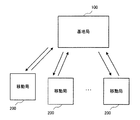
本実施の形態のデータ伝送システムは、無線ネットワークを構成し、データチャネルと制御チャネルとを備えるパケット形式のデータを互いに伝送する基地局100と複数(N個)の移動局200とを有している。
Hereinafter, embodiments of the present invention will be described in detail with reference to the drawings.
FIG. 2 is a block diagram illustrating an outline of the data transmission system according to the first embodiment.
The data transmission system according to the present embodiment includes a
無線回線は下りリンク(下り回線)と上りリンク(上り回線)とで構成されている。下りリンクにおいて基地局100から移動局200にデータが伝送され、上りリンクにおいてはその逆の伝送が行われる。なお、以下では、基地局100から移動局200に伝送するデータチャネル、制御チャネルを、それぞれ「下りのデータチャネル」、「下りの制御チャネル」といい、移動局200から基地局100に伝送するデータチャネル、制御チャネルを、それぞれ「上りのデータチャネル」、「上りの制御チャネル」という。また、各移動局200の構成は互いに等しいため、以下では代表的に基地局100と1つの移動局200とのデータの伝送について説明する。
The radio channel is composed of a downlink (downlink) and an uplink (uplink). Data is transmitted from the
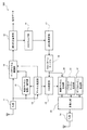
図3は、基地局を示すブロック図である。
基地局100は、下りトラフィック制御部2と、パイロットチャネル生成部3と、データチャネル生成部4と、制御チャネル生成部5と、多重化部6と、Tx(送信)部7と、Rx(受信)部8と、制御チャネル復調/復号部9とを有している。
FIG. 3 is a block diagram illustrating the base station.
The
下りトラフィック制御部2は、前述した適応無線リンク制御のスケジューリングを行う部位であり、分配部21と、移動局200の個数に対応するバッファ22(1)、22(2)、・・・、22(N)と、スケジューラ23と、選択部24とを有している。
The downlink
分配部21は、ネットワーク(図示せず)から伝送される送信データを、移動局(ユーザ)200毎にバッファ22(1)、22(2)、・・・、22(N)に格納する。
スケジューラ23は、移動局200毎のトラフィック量、優先度および制御チャネル復調/復号部9から得られるCQIおよびCQIのフォーマットに基づいて、移動局200間で送信のスケジューリングを行う。また、スケジューラ23は、CQIに基づいて、データチャネルの変調方式および符号化率を制御する適応変調を行う。
The
選択部24は、スケジューラ23の指示に従って、該当する移動局(ユーザ)200のデータを、バッファ22(1)、22(2)、・・・、22(N)から取り出す。
パイロットチャネル生成部3は、パイロットチャネルを生成する。
The
The pilot
データチャネル生成部4は、スケジューラ23により選択された移動局200のデータに対して符号化および変調を施す。
制御チャネル生成部5は、スケジューラ23から得られる情報、具体的には選択されたユーザの割り当て情報(ユーザID)、変調方式、符号化率、パケット番号、再送回数等の情報に基づいて、制御チャネルを生成する。
The data
The control
多重化部6は、符号化および変調が施された移動局200のデータと、生成されたパイロットチャネルおよび制御チャネルとを多重し、1つのパケット300を生成する。
図4は、第1の実施の形態の下りリンクのパケットの構成の一例を示す図である。
The
FIG. 4 is a diagram illustrating an example of a configuration of a downlink packet according to the first embodiment.
パケット300は、「パイロットチャネル」と、「制御チャネル」と、「データチャネル」とを有している。
再び図3に戻って説明する。
The
Returning to FIG. 3, the description will be continued.
Tx部7は、生成されたパケット300を移動局200に送信する。
Rx部8は、移動局200から送信されたパケットを受信する。
制御チャネル復調/復号部9は、受信したパケットから制御チャネルの復調/復号処理を行うことにより、移動局200から送られてくるCQIおよびCQIのフォーマットの情報を取得し、その情報をスケジューラ23に出力する。
The
The
The control channel demodulation /
図5は、第1の実施の形態の移動局を示すブロック図である。
移動局200は、Rx部11と、チャネル推定部12と、制御チャネル復調/復号部13と、データチャネル復調部14と、誤り訂正復号部15と、CRCチェック部16と、誤り率測定部17と、CQIパターンテーブル18と、CQI測定部19と、制御チャネル生成部20と、パイロットチャネル生成部31と、データチャネル生成部32と、多重化部33と、Tx部34とを有している。
FIG. 5 is a block diagram illustrating the mobile station according to the first embodiment.
The
チャネル推定部12は、Rx部11を介して得られるパケット300のパイロットチャネルを用いてチャネル(伝搬路)の推定を行いチャネル推定値を生成する。
制御チャネル復調/復号部13は、チャネル推定値を用いてパケット300から制御チャネルの復調および復号処理を行う。
The
The control channel demodulation /
データチャネル復調部14は、チャネル推定値を用いてパケット300からデータチャネルの復調処理を行って復調データを生成する。
誤り訂正復号部15は、復調データに対して誤り訂正処理を施し、復号データを生成する。
The
The error
CRCチェック部16は、復号データに誤りが生じていないかをチェックする。この誤りは、符号化後のデータチャネルに埋め込まれているCRC(Cyclic Redundancy Check)を用いることによりチェックされる。
The
誤り率測定部17は、CRCチェック部16での結果を平均することによって誤り率の測定を行うことにより下りのパケット(データチャネル)の通信品質を判定し、通信品質情報を生成する。
The error
通信品質はBER(ビットエラーレート)、BLER(ブロックエラーレート)等いくつかの指標を用いて測定する。本実施の形態では、BLERを用いている。
CQIパターンテーブル18には、通信品質情報に応じたCQIフォーマットが予めテーブル化されて格納されており、CQIパターンテーブル18では、通信品質情報に応じたCQIのフォーマットの選択(変更)を行う。
Communication quality is measured using several indicators such as BER (bit error rate) and BLER (block error rate). In this embodiment, BLER is used.
The CQI pattern table 18 stores a CQI format corresponding to communication quality information in advance, and the CQI pattern table 18 selects (changes) the CQI format corresponding to the communication quality information.
図6は、第1の実施の形態のCQIのフォーマットの一例を示す図である。
図6(a)に示すように、通信品質が悪い場合は、例えば−9〜+15dB(評価範囲)の間を3dB毎に8つに分解することで、3ビット(レベル1〜レベル8)のSIR情報を出力するCQIのフォーマット(パターン1)を選択する。一方、図6(b)に示すように、通信品質がよい場合は、例えば0〜20dBの間を5dBステップで4つに分解することで、2ビット(レベル1〜レベル4)のSIR情報を出力するCQIのフォーマット(パターン2)を選択する。
FIG. 6 is a diagram illustrating an example of a CQI format according to the first embodiment.
As shown in FIG. 6A, when the communication quality is poor, for example, by dividing the range between −9 to +15 dB (evaluation range) into 8 every 3 dB, 3 bits (
再び図5に戻って説明する。
CQI測定部19は、チャネル推定部12にて生成されたチャネル推定値を用いてSIRの計算を行い、このSIRとCQIのフォーマットとに基づいてCQIを生成する。
Returning again to FIG.
The
制御チャネル生成部20は、生成されたCQIとともに、選択されたCQIのフォーマットの情報を含む制御チャネルを生成する。
多重化部33は、この制御チャネルと、パイロットチャネル生成部31で生成されたパイロットチャネルおよびデータチャネル生成部32で生成されたデータチャネルとを多重化してパケット400を生成する。
The control
Tx部34は、パケット400を上りリンクによって基地局100に伝送(フィードバック)する。
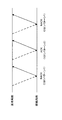
図7は、第1の実施の形態の上りリンクのパケットの構成の一例を示す図である。
The
FIG. 7 is a diagram illustrating an example of an uplink packet configuration according to the first embodiment.
なお、図7は、パケットの一部を示している。
パケット400は、図7中先頭側から「CQIヘッダ」、「CQI」、「データチャネル」を有している。
FIG. 7 shows a part of the packet.
The
CQIヘッダおよびCQIが制御チャネルを構成している領域であり、CQIヘッダ領域は、CQIのフォーマットの情報を有している。また、CQI領域は、移動局200で測定したCQIを有している。
The CQI header and the CQI are areas that constitute a control channel, and the CQI header area has information on the format of the CQI. Further, the CQI region has a CQI measured by the
データチャネル領域は、上りリンクのデータトラフィックを有している。また、図7には明示しないが、データチャネル領域の一部には、パイロットや、その他の制御情報が含まれていてもよい。図7に示すように、通信品質が悪い場合、すなわち、CQIの伝送量が多い場合は、データチャネルの伝送量が減少する。しかしながら、CQIの伝送量を増やすことで、適応無線リンク制御による利得が大きくなるため、通信品質が向上し、結果としてトータルのスループットを向上することができる。 The data channel region has uplink data traffic. Although not explicitly shown in FIG. 7, a part of the data channel region may include pilots and other control information. As shown in FIG. 7, when the communication quality is poor, that is, when the transmission amount of CQI is large, the transmission amount of the data channel decreases. However, increasing the amount of CQI transmission increases the gain due to adaptive radio link control, thereby improving communication quality and, as a result, improving the total throughput.
次に、第1の実施の形態のデータ伝送システムの動作について説明する。
まず、基地局100では送信データが移動局200毎のバッファ22(1)、22(2)、・・・、22(N)に格納される。次に、スケジューラ23により、移動局200毎のトラフィック量や優先度、移動局200から送られてくるCQIに基づいて、移動局200間で送信のスケジューリングが行われる。また、スケジューラ23により、移動局200からのCQIに基づいたデータチャネルの変調方式および符号化率が制御される。スケジューラ23により選択されたユーザのデータは、データチャネル生成部4において、符号化および変調が施され、多重化部6において、パイロットチャネルおよび制御チャネルと多重され、パケット300が生成される。そして、生成されたパケット300は、Tx部7を介して移動局200に伝送される。
Next, the operation of the data transmission system according to the first embodiment will be described.
First, in the
一方、移動局200では、Rx部11によりパケット300が受信され、チャネル推定部12により、パイロットチャネルを用いたチャネル推定が行われる。チャネル推定値は、制御チャネル復調/復号部13およびデータチャネル復調部14での復調処理に使われると同時に、CQI測定部19においてSIRのCQIに出力される。誤り訂正復号部15では、復調処理によって生成された復調データに対して誤り訂正処理が施され、復号データが生成される。そして、CRCチェック部16により復号データに誤りが生じていないか否かが判定される。次に、誤り率測定部17により、CRC結果が平均されることにより誤り率の測定が行われ、下りのデータチャネルの通信品質の判定が行われる。これにより、通信品質情報が生成される。そして、CQIパターンテーブル18により、通信品質情報に基づいてCQIのフォーマットが選択される。次に、CQI測定部19により、選択されたCQIのフォーマットに基づいたCQIが計算され、伝送するCQIが生成される。制御チャネル生成部20では、生成されたCQIとともに、CQIのフォーマットの情報を含むその他の制御情報が生成される。次に、多重化部33により、この制御チャネルと、パイロットチャネル生成部31で生成されたパイロットチャネルおよびデータチャネル生成部32で生成されたデータチャネルとが多重されパケット400が生成される。このパケット400は、Tx部34を介して上りリンクによって基地局100に伝送(フィードバック)される。
On the other hand, in the
その後、基地局100のRx部8を介して移動局200から送られてくるパケット400によりCQIおよびCQIのフォーマットの情報が取得されると、制御チャネル復調/復号部9により、制御チャネルの復調/復号処理が行われ、スケジューラ23により、フィードバックされた複数のフォーマットからなるCQIに基づいて、スケジューリングや適応変調等の制御が行われる。以降は、前述した動作を繰り返す。
Thereafter, when the CQI and CQI format information are acquired by the
以上述べたように、本実施の形態のデータ伝送システムによれば、適応無線リンク制御を行う際に、下りのデータチャネルの通信品質に応じて、CQIの評価範囲および評価レベルの分解能を変えることで、情報量の多いCQIパターン1と情報量の少ないCQIパターン2を生成する。これにより、下りリンクのスループットを大きく低下することなく、上りリンク(フィードバック回線)の負荷を低減することができる。さらに、上りリンクの使用状態に応じて、CQIフィードバックの伝送量を制御することで、下りリンクにおいて、高いスループットを維持することができる。
As described above, according to the data transmission system of the present embodiment, when adaptive radio link control is performed, the CQI evaluation range and evaluation level resolution are changed according to the communication quality of the downlink data channel. Thus, a
また、本実施の形態では、移動局200で測定したCQIを、上りリンクの制御チャネルによって基地局100へ伝送する際、基地局100側でCQIのフォーマットを識別する必要がある。そこで、上りリンクの制御チャネルによって、移動局200がどのフォーマットでCQIの伝送を行っているかを通知することにより、容易かつ確実に、伝送を行うことができる。
Further, in the present embodiment, when transmitting the CQI measured by the
また、本実施の形態では、データチャネルの通信品質に応じて、CQIの評価範囲と評価レベルの分解能との両方を変えたが、いずれか一方のみを変えてもよい。
次に、データ伝送システムの第2の実施の形態について説明する。
Further, in the present embodiment, both the CQI evaluation range and the evaluation level resolution are changed according to the communication quality of the data channel, but only one of them may be changed.
Next, a second embodiment of the data transmission system will be described.
以下、第2の実施の形態のデータ伝送システムについて、前述した第1の実施の形態のデータ伝送システムとの相違点を中心に説明し、同様の事項については、その説明を省略する。 Hereinafter, the data transmission system according to the second embodiment will be described with a focus on differences from the data transmission system according to the first embodiment described above, and description of similar matters will be omitted.
第2の実施の形態のデータ伝送システムは、下りのデータチャネルの通信品質として、再送制御のために基地局にフィードバックするACK/NACK信号を利用する点が異なっており、基地局100と、移動局200aとを有している。
The data transmission system according to the second embodiment is different from the
図8は、第2の実施の形態の移動局を示すブロック図である。
第2の実施の形態のデータ伝送システムでは再送制御を行い、再送制御に用いるACK/NACK信号に連動して、CQIのフォーマットを選択する。
FIG. 8 is a block diagram illustrating a mobile station according to the second embodiment.
In the data transmission system according to the second embodiment, retransmission control is performed, and a CQI format is selected in conjunction with an ACK / NACK signal used for retransmission control.
そのため、移動局200aは、誤り率測定部17の代わりにACK/NACK情報を生成するACK/NACK生成部17aを有している。また、CQIパターンテーブル18では、生成されたACK/NACK信号に基づいたCQIパターンを生成する。
Therefore, the
図9は、第2の実施の形態のCQIのフォーマットを説明する図である。
CQIパターンテーブル18では、通信品質が悪い、すなわちNACKであるときは、CQIの伝送量の多いフォーマット(パターン1)が選択される。一方、通信品質がよい、すなわち、ACKであるときは、CQIの伝送量の少ないフォーマット(パターン2)が選択される。
FIG. 9 is a diagram illustrating a CQI format according to the second embodiment.
In the CQI pattern table 18, when communication quality is poor, that is, NACK, a format (pattern 1) with a large CQI transmission amount is selected. On the other hand, when the communication quality is good, i.e., ACK, a format (pattern 2) with a small CQI transmission amount is selected.
再び図8に戻って説明する。
制御チャネル生成部20では、生成されたCQIとともに、ACK/NACK信号を含む制御チャネルを生成する。
Returning again to FIG.
The control
多重化部33は、この制御チャネルと、パイロットチャネル生成部31で生成されたパイロットチャネルおよびデータチャネル生成部32で生成されたデータチャネルとを多重化してパケット400aを生成する。
The multiplexing
Tx部34は、パケット400aを上りリンクによって基地局100に伝送(フィードバック)する。
図10は、第2の実施の形態の上りリンクのパケットの構成の一例を示す図である。
The
FIG. 10 is a diagram illustrating an example of an uplink packet configuration according to the second embodiment.
パケット400aは、図10中先頭側から「下りACK」、「CQI」、「データチャネル」を有している。
下りACKおよびCQIが制御チャネルを構成している領域であり、下りACK領域は、下りリンクのパケット300に対するACK/NACK信号を有している。より詳しくは、基地局100側で、スケジューラ23によって割り当てられた移動局200が、所定の処理遅延後のパケット300において下りACK/NACK信号をフィードバックする。
The
Downlink ACK and CQI are areas that constitute a control channel, and the downlink ACK area has an ACK / NACK signal for
この第2の実施の形態のデータ伝送システムによれば、第1の実施の形態のデータ伝送システムと同様の効果が得られる。
そして、第2の実施の形態のデータ伝送システムでは、再送制御を行う際には、ACK/NACKの情報に連動して、CQIのフォーマットを決定することにより(CQIの伝送方法を可変にすることで)、CQIのフォーマットをパケット400aの制御チャネルで通知する必要がなくなるとともに、誤り率測定部17を省略することができ、誤り率(下りリンクの通信品質)を別途測定する必要もなくなる。よって、簡易な制御で、上りリンク(フィードバック回線)の負荷を低減することができる。
According to the data transmission system of the second embodiment, the same effect as the data transmission system of the first embodiment can be obtained.
In the data transmission system of the second embodiment, when performing retransmission control, the CQI format is determined in conjunction with ACK / NACK information (the CQI transmission method is made variable). Therefore, it is not necessary to notify the CQI format through the control channel of the
次に、データ伝送システムの第3の実施の形態について説明する。
以下、第3の実施の形態のデータ伝送システムについて、前述した第2の実施の形態のデータ伝送システムとの相違点を中心に説明し、同様の事項については、その説明を省略する。
Next, a third embodiment of the data transmission system will be described.
Hereinafter, the data transmission system according to the third embodiment will be described focusing on the differences from the data transmission system according to the second embodiment described above, and description of similar matters will be omitted.
第3の実施の形態のデータ伝送システムは、下りのデータチャネルの通信品質として、移動局が再送制御のために基地局100から通知される再送回数を利用する点が異なっており、基地局100と移動局200bとを有している。
The data transmission system of the third embodiment is different in that the mobile station uses the number of retransmissions notified from the
図11は、第3の実施の形態の移動局を示すブロック図である。
移動局200bは、パケット300の制御チャネルによって得られる再送回数の情報を、移動局200bの制御チャネル復調/復号部13で受信する。
FIG. 11 is a block diagram illustrating a mobile station according to the third embodiment.
The
CQIパターンテーブル18は、受信結果に基づいてCQIのフォーマットを選択する。すなわち、基地局100が移動局200bに対して再送回数N回以上の再送を行っている場合は、通信品質が悪いと判断し、情報量の多いCQIのフォーマットを選択する。一方、基地局100が移動局200bに対して再送回数N回未満の再送を行っている場合は、通信品質がよいと判断し、情報量の少ないCQIのフォーマットを選択する。
The CQI pattern table 18 selects a CQI format based on the reception result. That is, when the
また、本実施の形態では、基地局100が再送回数の情報を把握しているため、上りの制御チャネルにおいて、CQIのフォーマットの情報を送信する必要はない。
この第3の実施の形態のデータ伝送システムによれば、再送回数と連動して、CQIのフォーマットを決定することにより、CQIのフォーマットを上りの制御チャネルで通知する必要がなくなると同時に、下りリンクの通信品質を測定する必要もなくなるため、第2の実施の形態のデータ伝送システムと同様の効果が得られる。
Further, in this embodiment, since
According to the data transmission system of the third embodiment, by determining the CQI format in conjunction with the number of retransmissions, it is not necessary to report the CQI format on the uplink control channel, and at the same time, the downlink Therefore, the same effect as that of the data transmission system of the second embodiment can be obtained.
次に、データ伝送システムの第4の実施の形態について説明する。
以下、第4の実施の形態のデータ伝送システムについて、前述した第1および第3の実施の形態のデータ伝送システムとの相違点を中心に説明し、同様の事項については、その説明を省略する。
Next, a fourth embodiment of the data transmission system will be described.
Hereinafter, the data transmission system according to the fourth embodiment will be described with a focus on differences from the data transmission systems according to the first and third embodiments described above, and descriptions of similar matters will be omitted. .
第4の実施の形態のデータ伝送システムは、CQIのフォーマットを選択する基準として、上りリンクの使用状況を用いる点が異なっており、基地局100aと移動局200cとを有している。
The data transmission system of the fourth embodiment is different in that an uplink usage status is used as a reference for selecting a CQI format, and includes a
図12は、第4の実施の形態の基地局を示すブロック図である。
基地局100aは、上りトラフィック制御部2aと、データチャネル復調/復号部30とをさらに有している。
FIG. 12 is a block diagram illustrating a base station according to the fourth embodiment.
The
データチャネル復調/復号部30は、受信したデータチャネルの復調処理を行って復調データを生成する。
上りトラフィック制御部2aは、分配部21aと、バッファ22a(1)、22a(2)、22a(3)、・・・、22a(N)と、トラフィック量測定部25とを有している。
The data channel demodulation /
The upstream
分配部21aは、復調データを、移動局(ユーザ)毎にバッファ22a(1)、22a(2)、22a(3)、・・・、22a(N)に格納する(ユーザ毎のパケットに再生される)。各バッファに格納されたデータ(受信データ)は、ネットワークに伝送される。
The
トラフィック量測定部25は、上りリンクのトータルのトラフィック量を測定した上りリンク使用状況を、制御チャネル生成部5に出力する。
制御チャネル生成部5は、上りリンク使用状況の情報を含む制御チャネルを生成する。
The traffic
The control
図13は、第4の実施の形態の移動局を示すブロック図である。
移動局200cのCQIパターンテーブル18は、下りの制御チャネルによって基地局100aから通知される上りリンクの使用状況の情報に基づいて、CQIのフォーマットを選択する。例えば、CQIパターンテーブル18は、上りリンクの使用状況に空きが多い場合は、誤り率測定部17で測定した誤り率(通信品質)が1%以上であるとき、CQIパターン1を選択し、誤り率が1%未満であるとき、CQIパターン2を選択するよう構成する。このように、通信品質の閾値を高く設定することによって、情報量の多いCQIのフォーマットを選択する頻度が高くなる。一方、上りリンクの使用状況に空きが少ない場合は、誤り率測定部17で測定した誤り率(通信品質)が5%以上であるとき、CQIパターン1を選択し、誤り率が5%未満であるとき、CQIパターン2を選択するよう構成する。このように、通信品質の閾値を低く設定することによって、情報量の少ないCQIのフォーマットを選択する頻度が高くなる。
FIG. 13 is a block diagram illustrating a mobile station according to the fourth embodiment.
The CQI pattern table 18 of the
次に、第4の実施の形態のデータ伝送システムの主要部分の動作について説明する。
移動局200cのCQIパターンテーブル18により、下りの制御チャネルによって基地局100aから通知される上りリンクの使用状況の情報に基づいて、CQIのフォーマットが選択される。
Next, operations of main parts of the data transmission system according to the fourth embodiment will be described.
The CQI format is selected based on the uplink usage status information notified from the
その後、Rx部8により受信された上りのデータチャネルは、上りトラフィック制御部2aに伝送され、ユーザ毎のパケットに再生される。そして、トラフィック量測定部25により、上りリンクのトータルのトラフィック量が測定され、上りリンク使用状況として、下りリンクの制御チャネル生成部5を介して移動局200cに通知される。
Thereafter, the uplink data channel received by the
この第4の実施の形態のデータ伝送システムによれば、第1および第3の実施の形態のデータ伝送システムと同様の効果が得られる。
そして、この第4の実施の形態では、上りリンクのデータトラフィックが下りリンクとは独立に割り当てられることを利用して、上りリンクのトラフィックが小さい場合にCQIの伝送量の多いフォーマットを積極的に利用することで、下りリンクのスループットの向上を図ることができる。
According to the data transmission system of the fourth embodiment, the same effect as the data transmission systems of the first and third embodiments can be obtained.
In the fourth embodiment, by utilizing the fact that uplink data traffic is allocated independently of the downlink, a format with a large CQI transmission amount is actively used when the uplink traffic is small. By using this, it is possible to improve downlink throughput.
次に、データ伝送システムの第5の実施の形態について説明する。
以下、第5の実施の形態のデータ伝送システムについて、前述した第1の実施の形態のデータ伝送システムとの相違点を中心に説明し、同様の事項については、その説明を省略する。
Next, a fifth embodiment of the data transmission system will be described.
Hereinafter, the data transmission system according to the fifth embodiment will be described focusing on the differences from the data transmission system according to the first embodiment described above, and description of similar matters will be omitted.
第5の実施の形態のデータ伝送システムは、伝送方法としてOFDMAを用いた点が異なっており、基地局100bと、移動局200dとを有している。
図14は、第5の実施の形態の基地局を示すブロック図である。
The data transmission system of the fifth embodiment is different in that OFDMA is used as a transmission method, and includes a
FIG. 14 is a block diagram illustrating a base station according to the fifth embodiment.
基地局100bでは、複数の周波数ブロックに対応するデータチャネルを生成するN個のデータチャネル生成部4a(1)、4a(2)、・・・、4a(N)を備え、さらにIFFT(Inverse Fast Fourier Transform:フーリエ逆変換)部41と、GI挿入部42とを有している。
The
多重化部6はパイロットチャネルと、各データチャネルと、制御チャネルとを多重する。
IFFT部41は、フーリエ逆変換して時間領域の信号に変換して1つのパケット500を生成する。
The
The
図15は、第5の実施の形態のパケットの構成の一例を示す図である。
パケット500は、無線リソースを周波数(サブキャリア)の単位に分割しキャリア毎にデータチャネルが周波数多重されている。また、データチャネルに対してパイロットチャネルおよび制御チャネルが時間多重されている。
FIG. 15 is a diagram illustrating an example of a packet configuration according to the fifth embodiment.
In the
再び図14に戻って説明する。
GI挿入部42は、フーリエ逆変換した信号にGI(Guard Interval)と呼ばれる区間を挿入する。これは、OFDM伝送において一般的に行われるマルチパス対策手法であり、詳細な説明は省略する。
Returning to FIG. 14, the description will be continued.
The
図16は、第5の実施の形態の移動局を示すブロック図である。
移動局200dは、GI除去部43と、FFT(Fast Fourier Transform:フーリエ変換)部44とを、さらに有している。
FIG. 16 is a block diagram illustrating a mobile station according to the fifth embodiment.
The
GI除去部43は、Rx部11を介して伝送された受信信号のGIを除去する。
FFT部44は、GIを除去した信号をフーリエ変換することで、受信信号をパケット500(周波数領域の信号)に変換する。
The
The
本実施の形態のCQIパターンテーブル18では、1つのCQIが報告する無線リソースの単位を可変にすることで、CQIの伝送量を調整する。
図17は、OFDMAを用いた場合のCQIのフォーマットの例を示す図である。
In the CQI pattern table 18 of the present embodiment, the amount of CQI transmission is adjusted by changing the unit of radio resources reported by one CQI.
FIG. 17 is a diagram illustrating an example of a CQI format when OFDMA is used.
図17では、12の周波数ブロックを用いて通信を行う例を示している。
移動局200dは、下りリンクのパイロットチャネルを用いて、周波数ブロック(バンド)毎のCQIを測定する。そして、通信品質が悪いときは、周波数ブロック毎の細かな周波数スケジューリングを行える、伝送量(情報量)の多いCQIのフォーマットを選択する。図17に示す例では、12種類のCQI(CQI(1)#1〜CQI(1)#12)を有するフォーマットを選択する(CQIパターン1)。一方、通信品質がよいときは、複数のバンドをまとめて周波数スケジューリングを行えるように、伝送量の少ないCQIのフォーマットを選択する。図17に示す例では、4つの周波数(サブキャリア)毎の平均である3種類のCQI(CQI(2)#1〜CQI(2)#3)を有するフォーマットを選択する(CQIパターン2)。これにより、通信品質がよい場合に、CQIのフィードバック伝送量を大幅に削減することができる。この方法では、通信品質が悪い場合は、細かい無線リソースの単位でCQIをフィードバックすることにより、適応リンク制御による利得が最大限得られるように制御を行う。また、通信品質がよい場合は、通信品質が悪いときに比べて荒い無線リソース単位でCQIをフィードバックすることで適応リンク制御を行う。この場合、元の通信品質がよいため、上りリンクのフィードバック伝送量を削減した場合においても確実に通信を行うことができる。
FIG. 17 shows an example in which communication is performed using 12 frequency blocks.
The
ここで、周波数割り当て方法について詳しく説明する。基地局100bは、通信品質の悪い移動局200dからは12の周波数ブロック単位でCQIを受信するが、通信品質のよい移動局200dからは3つの周波数ブロック単位でCQIを受信する。そこで、基地局100bは、通信品質の悪い移動局200dに対しては、12の周波数ブロックの中から平均CQIが閾値以上の周波数ブロックを選択する。また、基地局100bは、通信品質のよい移動局200dに対しては、3つの周波数ブロックの中から平均CQIが閾値以上の周波数ブロックを選択する。但し、通信品質がフェージング等の影響で変動したときに、12の周波数ブロックでCQIがフィードバックされたり、3つの周波数ブロックでフィードバックされたりする場合は、フィードバックされる周波数ブロック数の多い方に合わせて周波数ブロックの割り当てを行えばよい。すなわち、12の周波数ブロックでのフィードバック回数が多い場合は、12の周波数ブロックの平均CQIに基づいて、周波数ブロックの選択を行う。
Here, the frequency allocation method will be described in detail. The
次に、第5の実施の形態のデータ伝送システムの主要部分の動作について説明する。
データチャネル生成部4a(1)、4a(2)、・・・、4a(N)では、それぞれデータチャネルが生成され、IFFT部41によって周波数多重される。パイロットチャネルおよび制御チャネルは、データチャネルと時間多重され、全周波数帯域を利用して送信される。GI挿入部は、フーリエ逆変換した信号にGIを挿入する。
Next, the operation of the main part of the data transmission system according to the fifth embodiment will be described.
In data
一方、移動局200dでは、GIを除去した信号をフーリエ変換することで、受信信号を周波数領域に変換し、チャネル推定や制御チャネル復調/復号、データチャネル復調等の処理が行われる。
On the other hand, the
この第5の実施の形態のデータ伝送システムによれば、第1の実施の形態のデータ伝送システムと同様の効果が得られる。
そして、本発明のデータ伝送システムおよびデータ伝送方法は、OFDMAのようなCQIの伝送量が大きい伝送方法について、特に有効な手段になる。
According to the data transmission system of the fifth embodiment, the same effect as the data transmission system of the first embodiment can be obtained.
The data transmission system and data transmission method of the present invention are particularly effective means for a transmission method having a large CQI transmission amount such as OFDMA.
なお、図示はしないが、伝送方法としてMIMO多重伝送を用いてもよい。MIMO多重伝送を用いた場合について説明すると、通信品質が悪い場合は、複数の送信アンテナ毎に測定したCQIをフィードバックし、通信品質がよい場合は、複数の送信アンテナで測定した平均のCQIをフィードバックする。このように、アンテナ毎のCQIとアンテナ平均のCQIを切り換えることで、情報量の多いCQIパターンと情報量の少ないCQIパターンを生成することができる。このように、本発明で用いるCQIのフォーマットには、様々なパターンが考えられるため、対象とする無線アクセス方式に応じて、最適な制御が可能となるように、CQIのフォーマットを決めるとよい。 Although not shown, MIMO multiplex transmission may be used as a transmission method. The case where MIMO multiplex transmission is used will be described. When the communication quality is poor, the CQI measured for each of the plurality of transmission antennas is fed back. When the communication quality is good, the average CQI measured by the plurality of transmission antennas is fed back. To do. As described above, by switching between the CQI for each antenna and the CQI of the antenna average, a CQI pattern with a large amount of information and a CQI pattern with a small amount of information can be generated. As described above, since various patterns can be considered for the CQI format used in the present invention, the CQI format may be determined so that optimum control is possible according to the target wireless access scheme.
また、第5の実施の形態で説明したOFDMAに、MIMO多重伝送を組み合わせた場合においても容易かつ確実に上りリンクの負荷を低減することができるという顕著な効果が得られる。 Further, even when the OFDMA described in the fifth embodiment is combined with the MIMO multiplexing transmission, a remarkable effect is obtained that the uplink load can be easily and surely reduced.
以上、本発明のデータ伝送システムおよびデータ伝送方法を、図示の実施の形態に基づいて説明したが、本発明はこれに限定されるものではなく、各部の構成は、同様の機能を有する任意の構成のものに置換することができる。また、本発明に、他の任意の構成物や工程が付加されていてもよい。 As described above, the data transmission system and the data transmission method of the present invention have been described based on the illustrated embodiment. However, the present invention is not limited to this, and the configuration of each unit is an arbitrary one having the same function. It can be replaced with that of the configuration. Moreover, other arbitrary structures and processes may be added to the present invention.
また、本発明は、前述した各実施の形態のうちの、任意の2以上の構成(特徴)を組み合わせたものであってもよく、例えば、状況に応じて最適な無線リソースを選択して制御するよう構成されていてもよい。 Further, the present invention may be a combination of any two or more configurations (features) of the above-described embodiments. For example, the optimal radio resource is selected and controlled according to the situation. It may be configured to.
また、本発明で用いる、CQIのフォーマットは、2パターンに限定する必要はなく、複数パターンのCQIのフォーマットを予め決めておいてもよい。
なお、前述した各実施の形態では、1つの基地局と1つの移動局について説明したが、本発明は、これに限定されないことは言うまでもない。
Further, the CQI format used in the present invention need not be limited to two patterns, and a plurality of patterns of CQI formats may be determined in advance.
In each of the embodiments described above, one base station and one mobile station have been described. Needless to say, the present invention is not limited to this.
また、前述した各実施の形態では、通信品質情報に応じたCQIのフォーマットの選択は、CQIパターンテーブル18を用いたが、これに限らず、例えば、検量線や数式等を用いてもよい。 In each of the above-described embodiments, the CQI format selection according to the communication quality information is performed using the CQI pattern table 18. However, the present invention is not limited to this. For example, a calibration curve or a mathematical expression may be used.
(付記1) データチャネルを備えるパケットの送受信を行うデータ伝送システムにおいて、
前記パケットの伝搬路の品質に対応して与えられるCQIに基づいて前記パケットの通信品質が最大になる制御を行う制御部と、
前記パケットを生成するパケット生成部と、
前記パケットを送信する第1の送信部と、を有する送信局と、
前記パケットを受信する受信部と、
前記受信したパケットの通信品質に応じて前記CQIのフォーマットを変更するフォーマット変更部と、
前記CQIのフォーマットに基づいて前記CQIを測定する測定部と、
前記測定されたCQIを前記送信局に送信する第2の送信部と、を有する受信局と、
を備えることを特徴とするデータ伝送システム。
(Supplementary note 1) In a data transmission system for transmitting and receiving packets having a data channel,
A control unit that performs control to maximize the communication quality of the packet based on CQI given corresponding to the quality of the propagation path of the packet;
A packet generator for generating the packet;
A first transmitter that transmits the packet;
A receiving unit for receiving the packet;
A format changing unit that changes the format of the CQI according to the communication quality of the received packet;
A measurement unit that measures the CQI based on the format of the CQI;
A second transmission unit that transmits the measured CQI to the transmission station;
A data transmission system comprising:
(付記2) 前記パケットは、無線リソースを時間、周波数または空間の単位に分割し、そのうちの少なくとも1つを用いて生成され、
前記CQIのフォーマットは、分割した前記無線リソースの単位に基づいたフォーマットであることを特徴とする付記1記載のデータ伝送システム。
(Supplementary Note 2) The packet is generated by dividing radio resources into units of time, frequency, or space, and using at least one of them.
The data transmission system according to
(付記3) 前記パケットが、無線リソースを時間、周波数または空間の単位に分割したうちの2つ以上を用いて生成されているとき、前記制御部は、状況に応じて分割した前記無線リソースを選択して制御を行うことを特徴とする付記2記載のデータ伝送システム。
(Supplementary Note 3) When the packet is generated using two or more of radio resources divided into units of time, frequency, or space, the control unit determines the radio resources divided according to the situation. The data transmission system according to
(付記4) 前記パケットを送信する際に再送制御を行う場合、前記受信局は、前記データチャネルがACKであるかNACKであるかによって前記通信品質を判断することを特徴とする付記1記載のデータ伝送システム。 (Supplementary note 4) When performing retransmission control when transmitting the packet, the receiving station determines the communication quality based on whether the data channel is ACK or NACK. Data transmission system.
(付記5) 前記パケットを伝送する際に再送制御を行う場合、前記受信局は、前記パケットの再送回数に基づいて前記通信品質を判断することを特徴とする付記1記載のデータ伝送システム。
(Supplementary note 5) The data transmission system according to
(付記6) 前記パケットの通信品質は、主として前記送信局から前記受信局に前記パケットを送信する際の通信品質であることを特徴とする付記1記載のデータ伝送システム。
(Additional remark 6) The communication quality of the said packet is communication quality at the time of transmitting the said packet mainly from the said transmission station to the said receiving station, The data transmission system of
(付記7) 前記パケットの通信品質の情報は、前記データチャネルが有する情報であることを特徴とする付記1記載のデータ伝送システム。
(付記8) 前記フォーマット変更部は、前記パケットの通信品質がよいとき、伝送量の少ない前記CQIのフォーマットに変更し、前記パケットの通信品質が悪いとき、伝送量の多い前記CQIのフォーマットに変更することを特徴とする付記1記載のデータ伝送システム。
(Supplementary note 7) The data transmission system according to
(Supplementary Note 8) When the communication quality of the packet is good, the format changing unit changes the format of the CQI with a small transmission amount, and changes to the format of the CQI with a large transmission amount when the communication quality of the packet is bad. The data transmission system according to
(付記9) 前記パケットは、無線リソースを時間、周波数または空間の単位に分割し、そのうちの少なくとも1つを用いて生成され、
前記フォーマット変更部は、前記パケットの通信品質がよいとき、前記パケットの通信品質が悪いときよりも前記無線リソースの分割の単位が荒いフォーマットに変更することを特徴とする付記8記載のデータ伝送システム。
(Supplementary Note 9) The packet is generated by dividing radio resources into units of time, frequency, or space, and using at least one of them.
9. The data transmission system according to
(付記10) 前記受信局は、前記CQIが示す前記伝搬路の品質の評価範囲および評価レベルを演算する演算手段をさらに有し、
前記フォーマット変更部は、前記パケットの通信品質がよいとき、前記パケットの通信品質が悪いときよりも前記CQIの評価範囲および/または評価レベルの分解能が荒いフォーマットに変更することを特徴とする付記8記載のデータ伝送システム。
(Additional remark 10) The said receiving station further has a calculating means which calculates the evaluation range and evaluation level of the quality of the said propagation path which the said CQI shows,
The format change unit changes the format of the CQI evaluation range and / or the resolution of the evaluation level when the communication quality of the packet is good compared to when the communication quality of the packet is poor. The data transmission system described.
(付記11) 前記パケットの通信品質の情報は、予め前記受信局から前記送信局に与えられた情報であることを特徴とする付記1記載のデータ伝送システム。
(付記12) 前記受信局は、前記送信局に対して前記CQIと同時に、前記CQIのフォーマットを伝送することを特徴とする付記1記載のデータ伝送システム。
(Supplementary note 11) The data transmission system according to
(Supplementary note 12) The data transmission system according to
(付記13) 前記受信局は、前記受信局から前記送信局への前記伝搬路の空き状況に応じて前記CQIのフォーマットを選択する際の閾値を調整することを特徴とする付記1記載のデータ伝送システム。
(Supplementary note 13) The data according to
(付記14) 前記受信局から前記送信局への前記伝搬路の空き状況は、前記送信局から通知されることを特徴とする付記13記載のデータ伝送システム。
(付記15) データチャネルを備えるパケットの送受信を行うデータ伝送方法において、
送信局が、前記パケットの伝搬路の品質に対応して与えられるCQIに基づいて、前記パケットの通信品質が最大になる制御を行い、
前記パケットを生成し、
前記パケットを送信し、
受信局が、前記パケットを受信し、
前記受信したパケットの通信品質に応じて前記CQIのフォーマットを変更し、
前記CQIのフォーマットに基づいて、前記パケットのCQIを測定し、
前記測定されたCQIを前記送信局に送信する、
ことを特徴とするデータ伝送方法。
(Supplementary note 14) The data transmission system according to
(Supplementary Note 15) In a data transmission method for transmitting and receiving a packet including a data channel,
Based on the CQI given corresponding to the quality of the propagation path of the packet, the transmitting station performs control to maximize the communication quality of the packet,
Generate the packet,
Send the packet,
A receiving station receives the packet;
Changing the format of the CQI according to the communication quality of the received packet;
Measuring the CQI of the packet based on the format of the CQI;
Transmitting the measured CQI to the transmitting station;
A data transmission method characterized by the above.
2 下りトラフィック制御部
3 パイロットチャネル生成部
4 データチャネル生成部
5 制御チャネル生成部
6 多重化部
7、34 Tx部
8、11 Rx部
9 制御チャネル復調/復号部
12 チャネル推定部
13 制御チャネル復調/復号部
14 データチャネル復調部
15 誤り訂正復号部
16 CRCチェック部
17 誤り率測定部
17a ACK/NACK生成部
18 CQIパターンテーブル
19 CQI測定部
20 制御チャネル生成部
23 スケジューラ
50 送信局
51 制御部
52 パケット生成部
53、64 送信部
54、61 受信部
60 受信局
62 フォーマット変更部
63 測定部
100、100a、100b 基地局
200、200a、200b、200c、200d 移動局
300、400、400a、500 パケット
2 downlink
Claims (10)
前記無線通信についての通信品質に応じて、前記送信装置に送信する前記受信品質情報のデータ量を減少させる変更を行う変更部と、
変更された受信品質情報の形式に従って前記受信品質情報を送信する送信部と、
を備え、
前記変更部が、前記無線通信についての通信品質に応じて、前記送信装置に送信する前記受信品質情報の形式を変更する場合に、該変更部は、前記通信品質が良好な際の受信品質情報の形式に対して、前記通信品質が劣化した際の受信品質情報の形式がより詳細な情報となる変更を行う、
ことを特徴とする無線通信装置。 In a wireless communication device that performs wireless communication with a transmission device that performs transmission control based on reception quality information,
And in response to said communication Quality for wireless communication, changing unit to make changes to reduce the data amount of the reception quality information to be transmitted to the transmission device,
A transmission unit for transmitting the reception quality information in accordance with the format of the changed reception quality information;
With
When the changing unit changes the format of the reception quality information to be transmitted to the transmission device according to the communication quality for the wireless communication, the changing unit receives the reception quality information when the communication quality is good. Change the format of the reception quality information when the communication quality is deteriorated to be more detailed information.
A wireless communication apparatus.
ことを特徴とする請求項1記載の無線通信装置。 By changing the format of the reception quality information by the changing unit, the data amount of the reception quality information to be transmitted is changed.
The wireless communication apparatus according to claim 1.
ことを特徴とする請求項1記載の無線通信装置。 The changing unit changes the format of the reception quality information by changing the reception quality information obtained by collectively receiving the reception quality for a plurality of frequencies or a plurality of transmission antennas,
The wireless communication apparatus according to claim 1.
ことを特徴とする請求項1記載の無線通信装置。 When the changing unit changes the format of the reception quality information to be transmitted to the transmitting device according to the communication quality for the wireless communication, the changing unit is transmitted according to the deterioration of the communication quality. Change to increase the data amount of the received quality information,
The wireless communication apparatus according to claim 1.
ことを特徴とする請求項1記載の無線通信装置。 When the change unit changes the format of the reception quality information transmitted to the transmission device according to the data traffic received by the transmission device, the change unit receives the reception quality information when the traffic is high. Change the format of the reception quality information when the traffic is low to be more detailed information.
The wireless communication apparatus according to claim 1.
ことを特徴とする請求項1記載の無線通信装置。 As the communication quality, one of error rate, SIR, number of retransmissions, ACK / NACK is used.
The wireless communication apparatus according to claim 1.
前記無線通信についての通信品質に応じて、前記送信装置に送信する前記受信品質情報のデータ量を減少させる変更を行い、
前記無線通信についての通信品質に応じて、前記送信装置に送信する前記受信品質情報の形式を変更する場合に、前記通信品質が良好な際の受信品質情報の形式に対して、前記通信品質が劣化した際の受信品質情報の形式がより詳細な情報となる変更を行い、
変更された受信品質情報の形式に従って前記受信品質情報を送信する、
ことを特徴とする無線通信装置における送信方法。 In a transmission method for transmitting reception quality information in a wireless communication device that performs wireless communication with a transmission device that performs transmission control based on reception quality information,
In response to said communication Quality of radio communication, to make changes to reduce the data amount of the reception quality information to be transmitted to the transmission device,
When changing the format of the reception quality information to be transmitted to the transmission device according to the communication quality for the wireless communication, the communication quality is higher than the format of the reception quality information when the communication quality is good. Change the format of the reception quality information at the time of deterioration to become more detailed information,
Transmitting the reception quality information according to the format of the modified reception quality information;
A transmission method in a wireless communication apparatus.
通信品質に応じて、前記通信装置がデータ量を減少させる変更を行った受信品質情報を受信する受信部と、
受信した変更後の該受信品質情報に基づいて、送信制御を行う制御部と、
を備え、
前記通信装置が前記無線通信についての通信品質に応じて、前記送信装置に送信する前記受信品質情報の形式を変更する場合に、前記受信部が、前記通信品質が良好な際の受信品質情報の形式に対して、前記通信品質が劣化した際の受信品質情報の形式がより詳細な情報となる変更を行った受信品質情報を受信する、
ことを特徴とする送信装置。 In a transmission device that performs transmission control based on reception quality information received from a communication device,
Depending on the communication Quality, a receiving unit that the communication apparatus receives the reception quality information was modified to reduce the volume of data,
A control unit that performs transmission control based on the received reception quality information after the change,
With
When the communication device changes the format of the reception quality information to be transmitted to the transmission device according to the communication quality for the wireless communication, the reception unit receives the reception quality information when the communication quality is good. Receiving reception quality information that has been changed so that the format of the reception quality information when the communication quality is deteriorated with respect to the format becomes more detailed information.
A transmission apparatus characterized by the above.
前記パケットの伝搬路の品質に対応して与えられるCQIに基づいて前記パケットの通信品質が最大になる制御を行う制御部と、
前記パケットを生成するパケット生成部と、
前記パケットを送信する第1の送信部と、を有する送信局と、
前記パケットを受信する受信部と、
前記受信したパケットの通信品質に応じて、前記パケットの伝搬路の品質と前記CQIとの対応関係に関するフォーマットを変更するフォーマット変更部と、
前記フォーマットに基づいて前記CQIを測定する測定部と、
前記測定されたCQIを前記送信局に送信する第2の送信部と、を有する受信局と、
を備え、
前記フォーマット変更部は、前記パケットの伝搬路の品質に応じて、前記送信局に送信する前記CQIの前記フォーマットを変更する場合に、前記パケットの伝搬路の品質が良好な際の前記フォーマットの形式に対して、前記パケットの伝搬路の品質が劣化した際の前記フォーマットがより詳細となる変更を行う、
ことを特徴とするデータ伝送システム。 In a data transmission system that transmits and receives packets with a data channel,
A control unit that performs control to maximize the communication quality of the packet based on CQI given corresponding to the quality of the propagation path of the packet;
A packet generator for generating the packet;
A first transmitter that transmits the packet;
A receiving unit for receiving the packet;
A format changing unit that changes a format related to a correspondence relationship between the quality of the propagation path of the packet and the CQI according to the communication quality of the received packet;
A measurement unit for measuring the CQI based on the format;
A second transmission unit that transmits the measured CQI to the transmission station;
Equipped with a,
The format changing unit, when changing the format of the CQI transmitted to the transmitting station according to the quality of the propagation path of the packet, the format of the format when the quality of the propagation path of the packet is good In contrast, the format when the quality of the propagation path of the packet is deteriorated is changed to be more detailed.
A data transmission system characterized by that.
送信局が、前記パケットの伝搬路の品質に対応して与えられるCQIに基づいて、前記パケットの通信品質が最大になる制御を行い、
前記パケットを生成し、
前記パケットを送信し、
受信局が、前記パケットを受信し、
前記受信したパケットの通信品質に応じて、前記パケットの伝搬路の品質と前記CQIとの対応関係に関するフォーマットを変更し、
前記フォーマットに基づいて前記CQIを測定し、
前記測定されたCQIを前記送信局に送信し、
前記パケットの伝搬路の品質に応じて、前記送信局に送信する前記CQIの前記フォーマットを変更する場合に、前記パケットの伝搬路の品質が良好な際の前記フォーマットの形式に対して、前記パケットの伝搬路の品質が劣化した際の前記フォーマットがより詳細となる変更を行う、
ことを特徴とするデータ伝送方法。 In a data transmission method for transmitting and receiving packets comprising a data channel,
Based on the CQI given corresponding to the quality of the propagation path of the packet, the transmitting station performs control to maximize the communication quality of the packet,
Generate the packet,
Send the packet,
A receiving station receives the packet;
According to the communication quality of the received packet, the format regarding the correspondence between the quality of the propagation path of the packet and the CQI is changed,
Measuring the CQI based on the format;
Transmitting the measured CQI to the transmitting station,
When the format of the CQI to be transmitted to the transmitting station is changed according to the quality of the propagation path of the packet, the format of the format when the quality of the propagation path of the packet is good Change the format to be more detailed when the quality of the channel is degraded,
A data transmission method characterized by the above.
Priority Applications (5)
| Application Number | Priority Date | Filing Date | Title |
|---|---|---|---|
| JP2005285508A JP5063883B2 (en) | 2005-09-29 | 2005-09-29 | Wireless communication apparatus, transmission method, transmission apparatus, data transmission system, and data transmission method |
| EP20050257489 EP1770889A3 (en) | 2005-09-29 | 2005-12-06 | CQI transmission in an adaptive radio link |
| US11/298,454 US7813272B2 (en) | 2005-09-29 | 2005-12-12 | Data transmission system and method transmitting channel quality indicators in variable format |
| CN2005100230983A CN1941682B (en) | 2005-09-29 | 2005-12-26 | Data transmission system and method thereof |
| KR20050133084A KR100746816B1 (en) | 2005-09-29 | 2005-12-29 | Data transmission system and method |
Applications Claiming Priority (1)
| Application Number | Priority Date | Filing Date | Title |
|---|---|---|---|
| JP2005285508A JP5063883B2 (en) | 2005-09-29 | 2005-09-29 | Wireless communication apparatus, transmission method, transmission apparatus, data transmission system, and data transmission method |
Publications (3)
| Publication Number | Publication Date |
|---|---|
| JP2007096960A JP2007096960A (en) | 2007-04-12 |
| JP2007096960A5 JP2007096960A5 (en) | 2008-05-22 |
| JP5063883B2 true JP5063883B2 (en) | 2012-10-31 |
Family
ID=35976544
Family Applications (1)
| Application Number | Title | Priority Date | Filing Date |
|---|---|---|---|
| JP2005285508A Expired - Fee Related JP5063883B2 (en) | 2005-09-29 | 2005-09-29 | Wireless communication apparatus, transmission method, transmission apparatus, data transmission system, and data transmission method |
Country Status (5)
| Country | Link |
|---|---|
| US (1) | US7813272B2 (en) |
| EP (1) | EP1770889A3 (en) |
| JP (1) | JP5063883B2 (en) |
| KR (1) | KR100746816B1 (en) |
| CN (1) | CN1941682B (en) |
Families Citing this family (41)
| Publication number | Priority date | Publication date | Assignee | Title |
|---|---|---|---|---|
| EP1825628B1 (en) * | 2004-12-17 | 2011-02-09 | Telefonaktiebolaget LM Ericsson (publ) | Apparatus and method in a cellular network |
| KR101011408B1 (en) | 2005-06-16 | 2011-01-28 | 콸콤 인코포레이티드 | Negotiated channel information reporting in a wireless communication system |
| US20070149132A1 (en) | 2005-12-22 | 2007-06-28 | Junyl Li | Methods and apparatus related to selecting control channel reporting formats |
| JP4642679B2 (en) * | 2006-03-14 | 2011-03-02 | 富士通株式会社 | Wireless communication apparatus and wireless communication method |
| JP4760515B2 (en) * | 2006-04-28 | 2011-08-31 | 日本電気株式会社 | COMMUNICATION SYSTEM, COMMUNICATION METHOD THEREOF, AND MOBILE STATION AND BASE STATION USED FOR THE SAME |
| JP4869802B2 (en) * | 2006-06-19 | 2012-02-08 | 株式会社エヌ・ティ・ティ・ドコモ | Transmitting apparatus and communication method |
| CN102291230A (en) * | 2006-08-08 | 2011-12-21 | 松下电器产业株式会社 | Radio communication mobile station device and resource allocation method |
| JP4519817B2 (en) * | 2006-08-22 | 2010-08-04 | 株式会社エヌ・ティ・ティ・ドコモ | Base station and mobile station |
| JP4940867B2 (en) | 2006-09-29 | 2012-05-30 | 日本電気株式会社 | Multiplexing method of control signal and reference signal, resource allocation method and base station in mobile communication system |
| WO2008041168A2 (en) * | 2006-10-02 | 2008-04-10 | Nokia Corporation | Cqi feedback scheme |
| ES2538358T3 (en) | 2007-03-19 | 2015-06-19 | Telefonaktiebolaget L M Ericsson (Publ) | Use of an uplink grant as an activator of the first or second CQI report types |
| DE102007019292A1 (en) * | 2007-04-24 | 2008-10-30 | Rohde & Schwarz Gmbh & Co. Kg | Communication system and method with determination of channel parameters |
| KR101349825B1 (en) | 2007-04-25 | 2014-01-10 | 엘지전자 주식회사 | A method for transmitting feedback information in multiple input multiple output system |
| JP2008288990A (en) * | 2007-05-18 | 2008-11-27 | Tektronix Japan Ltd | Device and method for evaluating state of propagation path |
| US20090029714A1 (en) * | 2007-07-25 | 2009-01-29 | Rudrapatna Ashok N | Method of allocating bandwidth for transmission of channel quality information |
| US8630184B2 (en) * | 2007-08-15 | 2014-01-14 | Qualcomm Incorporated | Uplink control channel format |
| US20110222483A1 (en) * | 2007-08-15 | 2011-09-15 | Panasonic Corporation | Radio communication apparatus, radio communication system, and radio communication method |
| ES2400265T3 (en) * | 2007-09-06 | 2013-04-08 | Sharp Kabushiki Kaisha | Communication device and communication method |
| US8249179B2 (en) * | 2007-10-25 | 2012-08-21 | Sharp Kabushiki Kaisha | Communication apparatus, multicarrier communication system and communication method |
| US8570885B2 (en) * | 2008-02-19 | 2013-10-29 | Nxp, B.V. | Uplink feedback in a multimedia broadcast/multicast services (MBMS) wireless communications system |
| US8654900B2 (en) | 2008-04-25 | 2014-02-18 | Panasonic Corporation | Wireless communication device and quantization method |
| JP2010011063A (en) * | 2008-06-26 | 2010-01-14 | Panasonic Corp | Packet transmitter and packet transmission method |
| KR101513503B1 (en) * | 2008-08-11 | 2015-04-22 | 삼성전자주식회사 | - method and apparatus for the reduction of cqi reporting overhead in mobile telecommunication system supporting dual-cell hsdpa |
| US8644408B2 (en) | 2008-10-10 | 2014-02-04 | Qualcomm Incorporated | Method and apparatus for channel feedback in a wireless communication system |
| US20110305163A1 (en) * | 2009-02-25 | 2011-12-15 | Kyocera Corporation | Communication system, communication apparatus, and communication method |
| EP2230786A1 (en) * | 2009-03-16 | 2010-09-22 | Panasonic Corporation | Channel quality feedback signalling in communication systems |
| EP2285036A1 (en) * | 2009-08-12 | 2011-02-16 | Alcatel Lucent | Method of reporting scheduling information |
| WO2011082827A1 (en) * | 2010-01-08 | 2011-07-14 | Nokia Siemens Networks Oy | Apparatus and method to transmit/receive channel state information in a communication system |
| JP2011147002A (en) * | 2010-01-15 | 2011-07-28 | Kyocera Corp | Communication apparatus and communication method |
| RU2548903C2 (en) | 2010-02-10 | 2015-04-20 | Панасоник Интеллекчуал Проперти Корпорэйшн оф Америка | Terminal and communication method thereof |
| JP5322970B2 (en) * | 2010-02-16 | 2013-10-23 | Kddi株式会社 | Channel information compression control apparatus, channel information compression control method, receiver, and computer program |
| KR101751497B1 (en) * | 2010-06-11 | 2017-06-27 | 삼성전자주식회사 | Apparatus and method using matrix network coding |
| TWI427982B (en) * | 2010-10-01 | 2014-02-21 | Realtek Semiconductor Corp | Channel quality determining circuit and related method |
| JP5864184B2 (en) * | 2011-09-28 | 2016-02-17 | 京セラ株式会社 | Communications system |
| US10033601B2 (en) | 2012-12-28 | 2018-07-24 | Industrial Technology Research Institute | Method of reporting CQI and related communication device |
| US9838960B2 (en) | 2012-12-28 | 2017-12-05 | Industrial Technology Research Institute | Method of handling cell selection and related communication device |
| US9407417B2 (en) * | 2013-01-09 | 2016-08-02 | Qualcomm Incorporated | Identifying modulation and coding schemes and channel quality indicators |
| US10396945B2 (en) | 2014-11-07 | 2019-08-27 | Nokia Technologies Oy | Packet number representation for multicast channel block error rate reporting |
| CN107295673A (en) * | 2016-04-01 | 2017-10-24 | 索尼公司 | Electronic equipment and communication means in wireless communication system |
| RU2711514C1 (en) * | 2016-06-03 | 2020-01-17 | Телефонактиеболагет Лм Эрикссон (Пабл) | Administration of broken media flow control 5g |
| US10630453B2 (en) | 2017-08-10 | 2020-04-21 | At&T Intellectual Property I, L.P. | Facilitating restriction of channel state information to improve communication coverage in 5G or other next generation networks |
Family Cites Families (24)
| Publication number | Priority date | Publication date | Assignee | Title |
|---|---|---|---|---|
| GB9900126D0 (en) * | 1999-01-06 | 1999-02-24 | Univ Southampton | Wideband burst-by-burst adaptive H.263 assisted wireless video telephony |
| JP3826653B2 (en) | 2000-02-25 | 2006-09-27 | Kddi株式会社 | Subcarrier allocation method for wireless communication system |
| US6653041B2 (en) * | 2001-11-06 | 2003-11-25 | Hewlett-Packard Development Company, L.P. | UV toner fusing |
| CN1586048B (en) * | 2001-11-16 | 2012-07-11 | 皇家飞利浦电子股份有限公司 | Radio communication system |
| KR100834662B1 (en) * | 2001-11-21 | 2008-06-02 | 삼성전자주식회사 | Coding apparatus and method in a cdma mobile communication system |
| JP3875086B2 (en) * | 2001-11-30 | 2007-01-31 | ソフトバンクテレコム株式会社 | Orthogonal frequency division multiplexing system and transmitter / receiver |
| US7986672B2 (en) * | 2002-02-25 | 2011-07-26 | Qualcomm Incorporated | Method and apparatus for channel quality feedback in a wireless communication |
| KR100605859B1 (en) * | 2002-03-26 | 2006-07-31 | 삼성전자주식회사 | Apparatus and method for coding and decoding of cqi information in communication system using high speed downlink packet access scheme |
| KR100837351B1 (en) | 2002-04-06 | 2008-06-12 | 엘지전자 주식회사 | Update method for radio link parameter of mobile communication system |
| EP1388964B1 (en) | 2002-08-06 | 2006-11-22 | Mitsubishi Electric Information Technology Centre Europe B.V. | Transmission quality reporting method |
| KR100493158B1 (en) * | 2002-09-17 | 2005-06-02 | 삼성전자주식회사 | Adaptive hybrid ARQ method and method of transmitting and receiving data in system employing the same |
| JP2004112597A (en) * | 2002-09-20 | 2004-04-08 | Matsushita Electric Ind Co Ltd | Base station device and packet quality estimation method |
| JP3512783B1 (en) | 2002-10-08 | 2004-03-31 | 松下電器産業株式会社 | Communication terminal device and base station device |
| JP3796212B2 (en) * | 2002-11-20 | 2006-07-12 | 松下電器産業株式会社 | Base station apparatus and transmission allocation control method |
| EP1593222A1 (en) * | 2003-02-14 | 2005-11-09 | Siemens Aktiengesellschaft | Data transmission method |
| US20040179493A1 (en) | 2003-03-14 | 2004-09-16 | Khan Farooq Ullah | Methods of transmitting channel quality information and power allocation in wireless communication systems |
| JP2007521750A (en) * | 2003-06-26 | 2007-08-02 | インターデイジタル テクノロジー コーポレーション | A method for generating a channel quality indicator by biasing the signal-to-interference ratio. |
| JP4069034B2 (en) * | 2003-07-31 | 2008-03-26 | 松下電器産業株式会社 | Wireless transmission device, wireless reception device, wireless communication system, wireless transmission method, and wireless reception method |
| JP2005057710A (en) | 2003-08-07 | 2005-03-03 | Matsushita Electric Ind Co Ltd | Communication terminal device and base station device |
| JP4175510B2 (en) * | 2003-08-29 | 2008-11-05 | ソニー・エリクソン・モバイルコミュニケーションズ株式会社 | Mobile terminal, wireless relay device, mobile communication system |
| US20050170782A1 (en) * | 2004-02-04 | 2005-08-04 | Nokia Corporation | Method and apparatus to compensate quantization error of channel quality report |
| KR20050081528A (en) | 2004-02-14 | 2005-08-19 | 삼성전자주식회사 | Channel state information feedback method for multi-carrier communication system |
| KR20050091582A (en) * | 2004-03-12 | 2005-09-15 | 삼성전자주식회사 | Method for transmission of downlink channel quality indication in broadband wireless access system |
| EP1608099B1 (en) * | 2004-06-14 | 2012-08-15 | Samsung Electronics Co., Ltd. | Adaptive Modulation and Coding (AMC) in a MIMO system |
-
2005
- 2005-09-29 JP JP2005285508A patent/JP5063883B2/en not_active Expired - Fee Related
- 2005-12-06 EP EP20050257489 patent/EP1770889A3/en not_active Withdrawn
- 2005-12-12 US US11/298,454 patent/US7813272B2/en not_active Expired - Fee Related
- 2005-12-26 CN CN2005100230983A patent/CN1941682B/en not_active Expired - Fee Related
- 2005-12-29 KR KR20050133084A patent/KR100746816B1/en not_active IP Right Cessation
Also Published As
| Publication number | Publication date |
|---|---|
| US20070070956A1 (en) | 2007-03-29 |
| KR20070036570A (en) | 2007-04-03 |
| CN1941682B (en) | 2011-01-19 |
| KR100746816B1 (en) | 2007-08-06 |
| US7813272B2 (en) | 2010-10-12 |
| JP2007096960A (en) | 2007-04-12 |
| CN1941682A (en) | 2007-04-04 |
| EP1770889A3 (en) | 2008-10-01 |
| EP1770889A2 (en) | 2007-04-04 |
Similar Documents
| Publication | Publication Date | Title |
|---|---|---|
| JP5063883B2 (en) | Wireless communication apparatus, transmission method, transmission apparatus, data transmission system, and data transmission method | |
| US11496259B2 (en) | Methods and apparatus for multi-carrier communication systems with adaptive transmission and feedback | |
| JP4662496B2 (en) | Wireless communication system and wireless communication method | |
| US8457235B2 (en) | Method of transmitting feedback data in multiple antenna system | |
| US8233939B2 (en) | Multiuser sector micro diversity system | |
| KR101481166B1 (en) | Method for transmitting feedback data in multiple antenna system | |
| US20090041148A1 (en) | Open loop mu-mimo | |
| KR20090016386A (en) | Method for transmitting feedback data in multiple antenna system | |
| JP5501973B2 (en) | Reporting channel quality information | |
| JP4962584B2 (en) | Wireless communication system and wireless communication method | |
| WO2008143423A1 (en) | Method for transmitting control information |
Legal Events
| Date | Code | Title | Description |
|---|---|---|---|
| A521 | Request for written amendment filed |
Free format text: JAPANESE INTERMEDIATE CODE: A523 Effective date: 20080403 |
|
| A621 | Written request for application examination |
Free format text: JAPANESE INTERMEDIATE CODE: A621 Effective date: 20080403 |
|
| A977 | Report on retrieval |
Free format text: JAPANESE INTERMEDIATE CODE: A971007 Effective date: 20100208 |
|
| A131 | Notification of reasons for refusal |
Free format text: JAPANESE INTERMEDIATE CODE: A131 Effective date: 20100216 |
|
| A521 | Request for written amendment filed |
Free format text: JAPANESE INTERMEDIATE CODE: A523 Effective date: 20100414 |
|
| A02 | Decision of refusal |
Free format text: JAPANESE INTERMEDIATE CODE: A02 Effective date: 20100713 |
|
| A521 | Request for written amendment filed |
Free format text: JAPANESE INTERMEDIATE CODE: A523 Effective date: 20101012 |
|
| A911 | Transfer to examiner for re-examination before appeal (zenchi) |
Free format text: JAPANESE INTERMEDIATE CODE: A911 Effective date: 20101019 |
|
| A912 | Re-examination (zenchi) completed and case transferred to appeal board |
Free format text: JAPANESE INTERMEDIATE CODE: A912 Effective date: 20101112 |
|
| A521 | Request for written amendment filed |
Free format text: JAPANESE INTERMEDIATE CODE: A523 Effective date: 20120704 |
|
| A01 | Written decision to grant a patent or to grant a registration (utility model) |
Free format text: JAPANESE INTERMEDIATE CODE: A01 |
|
| A61 | First payment of annual fees (during grant procedure) |
Free format text: JAPANESE INTERMEDIATE CODE: A61 Effective date: 20120808 |
|
| R150 | Certificate of patent or registration of utility model |
Free format text: JAPANESE INTERMEDIATE CODE: R150 |
|
| FPAY | Renewal fee payment (event date is renewal date of database) |
Free format text: PAYMENT UNTIL: 20150817 Year of fee payment: 3 |
|
| LAPS | Cancellation because of no payment of annual fees |