JP4662496B2 - Wireless communication system and wireless communication method - Google Patents
Wireless communication system and wireless communication method Download PDFInfo
- Publication number
- JP4662496B2 JP4662496B2 JP2007501473A JP2007501473A JP4662496B2 JP 4662496 B2 JP4662496 B2 JP 4662496B2 JP 2007501473 A JP2007501473 A JP 2007501473A JP 2007501473 A JP2007501473 A JP 2007501473A JP 4662496 B2 JP4662496 B2 JP 4662496B2
- Authority
- JP
- Japan
- Prior art keywords
- symbol
- frame
- control
- propagation path
- unit
- Prior art date
- Legal status (The legal status is an assumption and is not a legal conclusion. Google has not performed a legal analysis and makes no representation as to the accuracy of the status listed.)
- Active
Links
Images


Classifications
-
- H—ELECTRICITY
- H04—ELECTRIC COMMUNICATION TECHNIQUE
- H04B—TRANSMISSION
- H04B1/00—Details of transmission systems, not covered by a single one of groups H04B3/00 - H04B13/00; Details of transmission systems not characterised by the medium used for transmission
- H04B1/76—Pilot transmitters or receivers for control of transmission or for equalising
-
- H—ELECTRICITY
- H04—ELECTRIC COMMUNICATION TECHNIQUE
- H04B—TRANSMISSION
- H04B7/00—Radio transmission systems, i.e. using radiation field
- H04B7/02—Diversity systems; Multi-antenna system, i.e. transmission or reception using multiple antennas
- H04B7/04—Diversity systems; Multi-antenna system, i.e. transmission or reception using multiple antennas using two or more spaced independent antennas
- H04B7/06—Diversity systems; Multi-antenna system, i.e. transmission or reception using multiple antennas using two or more spaced independent antennas at the transmitting station
- H04B7/0613—Diversity systems; Multi-antenna system, i.e. transmission or reception using multiple antennas using two or more spaced independent antennas at the transmitting station using simultaneous transmission
- H04B7/0615—Diversity systems; Multi-antenna system, i.e. transmission or reception using multiple antennas using two or more spaced independent antennas at the transmitting station using simultaneous transmission of weighted versions of same signal
- H04B7/0617—Diversity systems; Multi-antenna system, i.e. transmission or reception using multiple antennas using two or more spaced independent antennas at the transmitting station using simultaneous transmission of weighted versions of same signal for beam forming
-
- H—ELECTRICITY
- H04—ELECTRIC COMMUNICATION TECHNIQUE
- H04B—TRANSMISSION
- H04B7/00—Radio transmission systems, i.e. using radiation field
- H04B7/24—Radio transmission systems, i.e. using radiation field for communication between two or more posts
- H04B7/26—Radio transmission systems, i.e. using radiation field for communication between two or more posts at least one of which is mobile
- H04B7/2643—Radio transmission systems, i.e. using radiation field for communication between two or more posts at least one of which is mobile using time-division multiple access [TDMA]
- H04B7/2656—Radio transmission systems, i.e. using radiation field for communication between two or more posts at least one of which is mobile using time-division multiple access [TDMA] for structure of frame, burst
-
- H—ELECTRICITY
- H04—ELECTRIC COMMUNICATION TECHNIQUE
- H04L—TRANSMISSION OF DIGITAL INFORMATION, e.g. TELEGRAPHIC COMMUNICATION
- H04L1/00—Arrangements for detecting or preventing errors in the information received
- H04L1/0001—Systems modifying transmission characteristics according to link quality, e.g. power backoff
- H04L1/0006—Systems modifying transmission characteristics according to link quality, e.g. power backoff by adapting the transmission format
-
- H—ELECTRICITY
- H04—ELECTRIC COMMUNICATION TECHNIQUE
- H04L—TRANSMISSION OF DIGITAL INFORMATION, e.g. TELEGRAPHIC COMMUNICATION
- H04L1/00—Arrangements for detecting or preventing errors in the information received
- H04L1/0001—Systems modifying transmission characteristics according to link quality, e.g. power backoff
- H04L1/0015—Systems modifying transmission characteristics according to link quality, e.g. power backoff characterised by the adaptation strategy
-
- H—ELECTRICITY
- H04—ELECTRIC COMMUNICATION TECHNIQUE
- H04L—TRANSMISSION OF DIGITAL INFORMATION, e.g. TELEGRAPHIC COMMUNICATION
- H04L1/00—Arrangements for detecting or preventing errors in the information received
- H04L1/12—Arrangements for detecting or preventing errors in the information received by using return channel
- H04L1/16—Arrangements for detecting or preventing errors in the information received by using return channel in which the return channel carries supervisory signals, e.g. repetition request signals
- H04L1/1607—Details of the supervisory signal
- H04L1/1671—Details of the supervisory signal the supervisory signal being transmitted together with control information
-
- H—ELECTRICITY
- H04—ELECTRIC COMMUNICATION TECHNIQUE
- H04L—TRANSMISSION OF DIGITAL INFORMATION, e.g. TELEGRAPHIC COMMUNICATION
- H04L5/00—Arrangements affording multiple use of the transmission path
- H04L5/003—Arrangements for allocating sub-channels of the transmission path
- H04L5/0048—Allocation of pilot signals, i.e. of signals known to the receiver
- H04L5/0051—Allocation of pilot signals, i.e. of signals known to the receiver of dedicated pilots, i.e. pilots destined for a single user or terminal
-
- H—ELECTRICITY
- H04—ELECTRIC COMMUNICATION TECHNIQUE
- H04L—TRANSMISSION OF DIGITAL INFORMATION, e.g. TELEGRAPHIC COMMUNICATION
- H04L1/00—Arrangements for detecting or preventing errors in the information received
- H04L1/0001—Systems modifying transmission characteristics according to link quality, e.g. power backoff
- H04L1/0023—Systems modifying transmission characteristics according to link quality, e.g. power backoff characterised by the signalling
- H04L1/0026—Transmission of channel quality indication
-
- H—ELECTRICITY
- H04—ELECTRIC COMMUNICATION TECHNIQUE
- H04L—TRANSMISSION OF DIGITAL INFORMATION, e.g. TELEGRAPHIC COMMUNICATION
- H04L5/00—Arrangements affording multiple use of the transmission path
- H04L5/0001—Arrangements for dividing the transmission path
- H04L5/0003—Two-dimensional division
- H04L5/0005—Time-frequency
- H04L5/0007—Time-frequency the frequencies being orthogonal, e.g. OFDM(A), DMT
Description
本発明は無線通信システムおよび無線通信方法に係わり、特に、伝搬路推定に用いる基本パイロットシンボルと、データチャネルの復調に必要な制御情報を伝達する制御シンボルと、情報ビットを伝達するデータシンボルを備えたフレームを送受信する無線通信システムおよびに無線通信方法に関する。 The present invention relates to a radio communication system and a radio communication method, and in particular, includes a basic pilot symbol used for channel estimation, a control symbol for transmitting control information necessary for data channel demodulation, and a data symbol for transmitting information bits. The present invention relates to a wireless communication system that transmits and receives a frame and a wireless communication method.
セルラー移動通信におけるパケット伝送では、データパケットの伝送効率を高めるために、適応変復調制御、適応拡散率制御、送信電力制御、HARQ(Hybrid Automatic Repeat reQuest)制御、スケジューリング制御などの適応無線リンク制御が用いられる。これらの制御は、データチャネルと同時に送信される制御チャネルを用いて行われ、送信局は、制御チャネルによってデータチャネルで使用している無線リンクパラメータを受信局に通知する。例えば、適応変復調制御の場合、制御チャネルはデータチャネルの変調方式(QPSK,16QAM等)および符号化率を伝送する。また、適応拡散率制御の場合は、制御チャネルは拡散率や拡散コード、またはシンボル繰返し回数などの情報を伝送する。HARQ制御では、制御チャネルはデータチャネルで伝送されるパケット番号や再送回数などの情報を伝送する。スケジューリング制御を行う場合は、ユーザIDなどの情報を制御チャネルを用いて伝送する。 In packet transmission in cellular mobile communications, adaptive radio link control such as adaptive modulation / demodulation control, adaptive spreading factor control, transmission power control, HARQ (Hybrid Automatic Repeat reQuest) control, scheduling control, etc. is used to increase the transmission efficiency of data packets. It is done. These controls are performed using a control channel transmitted simultaneously with the data channel, and the transmitting station notifies the receiving station of radio link parameters used in the data channel by the control channel. For example, in the case of adaptive modulation / demodulation control, the control channel transmits a data channel modulation scheme (QPSK, 16QAM, etc.) and a coding rate. In the case of adaptive spreading factor control, the control channel transmits information such as spreading factor, spreading code, or symbol repetition count. In HARQ control, the control channel transmits information such as the packet number and the number of retransmissions transmitted on the data channel. When scheduling control is performed, information such as a user ID is transmitted using a control channel.
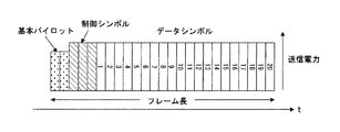
図22に、セルラー移動通信のパケット伝送に用いられる従来のフレーム構成を示す。1つのフレームは、基本パイロットシンボルSPと制御シンボルSCとデータシンボルSDによって構成されている。基地局が送信を行う下りリンクにおいては、基本パイロットシンボルSPは、共通パイロットと考えてもよい。基本パイロットシンボルSPは、制御チャネルおよびデータチャネルの信号を復調するための伝搬路推定に用いられる。データチャネルでは、適応無線リンク制御によって、変調方式・符号化率・拡散率・送信電力などが制御される。これらの制御パラメータは、制御シンボルSCによって通知される。
適応無線リンク制御では、セル端などの通信品質の低いユーザに対しては、データチャネルの通信品質を向上したり、通信品質の悪い環境においても誤りが発生しない伝送方法への切り替えなどの制御が行われる。図23は、セル端などの通信品質の低いユーザに対して、送信電力制御が行われた場合の例である。下りリンクにおいては、図23のように、基本パイロットシンボルの電力は一定に保たれたまま、制御シンボルおよびデータシンボルの送信電力が大きくなるように制御される。このように、図23の例では、制御チャネルやデータチャネルに対しては、送信電力制御によって、通信品質を向上する制御が行われているが、基本パイロットシンボルに対しては、適応的な制御は行われない。したがって、通常、下りリンクでは、基本パイロットシンボルに対して、やや大きめの送信電力が割り当てられる。しかしながら、セル端においては、他セルからの干渉の影響などがあるため、パイロットシンボルによるチャネル推定精度は他セル干渉によって劣化する傾向にある。FIG. 22 shows a conventional frame configuration used for packet transmission of cellular mobile communication. One frame is constituted by the basic pilot symbols S P and the control symbols S C and the data symbols S D. In the downlink the base station performs transmission, the basic pilot symbols S P may be considered as a common pilot. Basic pilot symbols S P is used for channel estimation for demodulating the signal of the control channel and the data channel. In the data channel, modulation scheme, coding rate, spreading factor, transmission power, and the like are controlled by adaptive radio link control. These control parameters are notified by the control symbol S C.
In adaptive radio link control, for users with low communication quality such as cell edges, control such as improving the data channel communication quality or switching to a transmission method that does not cause errors even in an environment with poor communication quality. Done. FIG. 23 is an example when transmission power control is performed for a user with low communication quality such as a cell edge. In the downlink, as shown in FIG. 23, control is performed such that the transmission power of control symbols and data symbols is increased while the power of basic pilot symbols is kept constant. Thus, in the example of FIG. 23, control for improving the communication quality is performed for the control channel and the data channel by transmission power control, but adaptive control is performed for the basic pilot symbols. Is not done. Therefore, normally, a slightly larger transmission power is allocated to the basic pilot symbol in the downlink. However, at the cell edge, because of the influence of interference from other cells, the channel estimation accuracy by pilot symbols tends to deteriorate due to other cell interference.
図24は、セル端などの通信品質の低いユーザに対して、適応拡散率制御が行われた場合の例である。この例では、データシンボルの繰返し回数を増やすことによって、データチャネルのS/Nを改善している。このように、図24の例においても、データチャネルに対しては、シンボル繰返し数を制御することによって、通信品質を改善する制御が行われるが、パイロットシンボルに対しては、S/Nを改善するような適応的な制御は行われない。
このように、従来のパケット伝送方法では、セル端などの通信品質の低いユーザ端末と基地局の間では、適応無線リンク制御によってデータチャネルの通信品質が保証されるが、
復調特性に大きく影響するパイロットシンボルに対しては、適応的な制御を行う仕組みが存在しなかった。したがって、復調に用いるチャネル推定値の推定精度が改善されずに、データチャネルの復調特性が改善しなくなる限界が生じてしまう問題があった。FIG. 24 is an example when adaptive spreading factor control is performed for a user with low communication quality such as a cell edge. In this example, the S / N of the data channel is improved by increasing the number of repetitions of the data symbol. Thus, in the example of FIG. 24 as well, control for improving communication quality is performed for the data channel by controlling the number of symbol repetitions, but S / N is improved for pilot symbols. Such adaptive control is not performed.
Thus, in the conventional packet transmission method, between the user terminal with a low communication quality such as a cell edge and the base station, the communication quality of the data channel is guaranteed by the adaptive radio link control.
There is no mechanism for performing adaptive control on pilot symbols that greatly affect the demodulation characteristics. Therefore, there has been a problem that the estimation accuracy of the channel estimation value used for demodulation is not improved, and there is a limit that the demodulation characteristics of the data channel are not improved.
第1従来技術として正規のパイロットシンボルの他に、所定の制御シンボル、たとえば3GPP標準によるTFCI(Transport Format Combination Indicator)制御シンボルをパイロットシンボルとして使用する技術がある(たとえば特許文献1参照)。この第1従来技術によれば、パイロットシンボルとして使用されるシンボル数が増大する結果、チャネル推定精度を向上できる。
第2従来技術として、プリアンブル部とペイロード部に分かれている無線LANのフォーマットに対して、プリアンブル部だけでなく、ペイロード部においてもパイロットシンボルを挿入する技術がある(たとえば特許文献2参照)。
しかし、第1従来技術は、追加パイロットシンボルの挿入を適応的に行うものではない。また、第1従来技術は、3GPP標準による特定の性質を利用するもので一般的な無線通信のチャネル推定に適用できない。
また、第2従来技術は、追加パイロットシンボルの挿入を適応的に行う方法ではなく、常に、プリアンブル部とペイロード部にパイロットシンボルを挿入するもので、パイロットシンボル数が多くなって伝送効率が低下する問題がある。As a first conventional technique, there is a technique that uses a predetermined control symbol, for example, a TFCI (Transport Format Combination Indicator) control symbol based on the 3GPP standard, as a pilot symbol in addition to a regular pilot symbol (see, for example, Patent Document 1). According to the first conventional technique, the number of symbols used as pilot symbols increases, and as a result, channel estimation accuracy can be improved.
As a second conventional technique, there is a technique in which pilot symbols are inserted not only in the preamble part but also in the payload part for a wireless LAN format divided into a preamble part and a payload part (see, for example, Patent Document 2).
However, the first prior art does not adaptively insert additional pilot symbols. The first prior art uses a specific property based on the 3GPP standard and cannot be applied to general wireless communication channel estimation.
Further, the second prior art is not a method of adaptively inserting additional pilot symbols, but always inserts pilot symbols in the preamble part and the payload part, resulting in an increase in the number of pilot symbols and a decrease in transmission efficiency. There's a problem.
以上から本発明の目的は、伝搬路状態に基づいて追加パイロットシンボルの挿入を適応的に行えるようにしてチャネル推定精度を向上することである。
本発明の別の目的は、移動速度が速くフェージング周波数が高い場合にもチャネル推定精度を適応的に向上することである。
本発明の別の目的は、伝搬路状態に基づいて送信方式(データシンボルの変調方式、符号化率、拡散率、送信電力など)を制御する適応制御と関連付けながら、パイロットシンボルの追加制御を行うことである。
本発明の別の目的は、伝搬路状態に基づいてあるいは要求に基づいて、1本の送信アンテナによる送信からMIMO(Multiple-Input Multiple-Output)や送信ビームフォーミングなどのように複数の送信アンテナによる送信に切り換えることである。
本発明の別の目的は、基本パイロットシンボルの電力やシンボル数をあらかじめ小さく設定できるようにすることである。
本発明の別の目的は、受信側で追加パイロットシンボルの有無やシンボル数、追加される位置を識別して追加パイロットシンボルを用いたチャネル推定を可能にすることである。
Another object of the present invention is to adaptively improve channel estimation accuracy even when the moving speed is high and the fading frequency is high.
Another object of the present invention is to perform additional control of pilot symbols while associating with adaptive control for controlling the transmission scheme (data symbol modulation scheme, coding rate, spreading factor, transmission power, etc.) based on the propagation path state. That is.
Another object of the present invention is to use a plurality of transmission antennas such as MIMO (Multiple-Input Multiple-Output) or transmission beamforming from transmission by one transmission antenna based on a propagation path state or on demand. Switching to transmission.
Another object of the present invention is to enable the power and number of basic pilot symbols to be set small in advance.
Another object of the present invention is to enable the channel estimation using the additional pilot symbols by identifying the presence / absence of the additional pilot symbols, the number of symbols, and the added positions on the receiving side.
本発明は伝搬路推定に用いる基本パイロットシンボルと、データチャネルの復調に必要な制御情報を伝達する制御シンボルと、情報ビットを伝達するデータシンボルを備えたフレームを送受信する無線通信システムおよび無線通信方法である。
本発明の無線通信システムにおいて、送信装置は、基本パイロットシンボルとは別のパイロットシンボルをフレームに追加するか否かを決定するパイロット追加決定部、追加パイロットシンボルに関する情報を含む制御シンボルを生成する制御シンボル生成部、前記パイロットシンボルの追加決定により、前記パイロットシンボルを追加されたフレームを組立てるフレーム組立部、該フレームを送信する送信部を備えている。
また、送信装置は、受信装置との間の伝搬路状態に関する伝搬路情報を取得して出力する伝搬路情報出力部を備え、前記パイロット追加決定部は、該伝搬路情報に基づいて追加パイロットシンボルの有無および追加パイロットシンボルの数を決定する。
また、送信装置は、受信装置の移動速度を取得する移動速度取得部を備え、前記パイロ
ット追加決定部は、該受信装置の移動速度に応じて、追加パイロットシンボルをデータシンボル領域内に分散して配置するか否か及び追加パイロットシンボル位置を決定する。
また、送信装置は、受信装置との間の伝搬路状態に関する伝搬路情報を取得して出力する伝搬路情報出力部、前記伝搬路情報に基づいて送信方式を適応的に制御する適応制御部を備え、前記パイロット追加決定部は、適応制御によっても伝送誤りが改善しないときに、パイロットシンボルの追加を決定する。
また、送信装置は、複数の送信アンテナと、各送信アンテナに対応する送信部を備え、前記フレーム組立部は、パイロットシンボルを追加しない場合、1本の送信アンテナから送信する追加パイロットシンボルを含まないフレームを組み立て、パイロットシンボルを追加する場合、前記1本の送信アンテナから送信する前記フレームと、他の送信アンテナから送信するフレームであって、追加パイロットシンボルを含み、基本パイロットシンボル及び制御シンボルを含まないフレームとを組み立てる。The present invention relates to a radio communication system and a radio communication method for transmitting and receiving a frame including a basic pilot symbol used for channel estimation, a control symbol for transmitting control information necessary for data channel demodulation, and a data symbol for transmitting information bits. It is.
In the wireless communication system of the present invention, the transmitting apparatus controls to generate a control symbol including information related to an additional pilot symbol, a pilot addition determining unit that determines whether or not to add a pilot symbol different from the basic pilot symbol to the frame. A symbol generating unit; a frame assembling unit that assembles a frame to which the pilot symbol is added according to addition determination of the pilot symbol; and a transmitting unit that transmits the frame.
The transmission apparatus includes a propagation path information output unit that acquires and outputs propagation path information related to a propagation path state with the reception apparatus, and the pilot addition determination unit adds an additional pilot symbol based on the propagation path information. And the number of additional pilot symbols.
The transmission apparatus includes a movement speed acquisition unit that acquires a movement speed of the reception apparatus, and the pilot addition determination unit distributes additional pilot symbols in the data symbol area according to the movement speed of the reception apparatus. Determine whether to place and additional pilot symbol positions.
Further, the transmission apparatus includes a propagation path information output unit that acquires and outputs propagation path information related to a propagation path state with the reception apparatus, and an adaptive control unit that adaptively controls a transmission scheme based on the propagation path information. The pilot addition determining unit determines addition of a pilot symbol when transmission errors are not improved even by adaptive control.
The transmission apparatus includes a plurality of transmission antennas and a transmission unit corresponding to each transmission antenna, and the frame assembly unit does not include an additional pilot symbol transmitted from one transmission antenna when no pilot symbol is added. When assembling a frame and adding pilot symbols, the frame transmitted from the one transmission antenna and the frame transmitted from another transmission antenna, including additional pilot symbols, including basic pilot symbols and control symbols Assemble with no frame.
本発明の無線通信システムの受信装置は、受信フレームに含まれる制御シンボルを復調し、該制御シンボル情報に基づいて受信フレームに追加パイロットシンボルが含まれているか判定する制御シンボル復調部、追加パイロットシンボルが含まれている場合には、該追加パイロットシンボルを用いて伝搬路を推定する伝搬路推定部、該伝搬路推定値に基づいてデータシンボルを復調するデータシンボル復調部を備えている。
また、受信装置の伝搬路推定部は、前記基本パイロットシンボルを用いて伝搬路を推定する第1の伝搬路推定部、追加パイロットシンボルが存在すれば、該追加パイロットシンボルを用いて伝搬路の推定を行う第2の伝搬路推定部を備え、前記制御シンボル復調部は第1の伝搬路推定部で推定された第1の伝搬路推定値を用いて制御シンボルを復調し、前記データシンボル復調部は、前記制御シンボル情報と前記第2の伝搬路推定部で推定した第2の伝搬路推定値を用いてデータシンボルを復調する。
また、受信装置は、制御チャネルに含まれる追加パイロット情報の誤りを検出する誤り検出部を備え、追加パイロット情報に伝送誤りが生じていなければ、前記第2の伝搬路推定値に基づいて再度制御シンボルを復調する第2の制御シンボル復調部を備え、前記データシンボル復調部は、前記第2の制御シンボル復調部で復調した制御シンボルと前記第2の伝搬路推定値を用いてデータシンボルを復調する。A receiving apparatus of a radio communication system of the present invention demodulates a control symbol included in a received frame, and determines whether an additional pilot symbol is included in the received frame based on the control symbol information, an additional pilot symbol Is included, a propagation path estimation unit that estimates a propagation path using the additional pilot symbol and a data symbol demodulation unit that demodulates a data symbol based on the propagation path estimation value are provided.
In addition, the propagation path estimation unit of the reception apparatus is a first propagation path estimation unit that estimates a propagation path using the basic pilot symbols. If there is an additional pilot symbol, the propagation path estimation is performed using the additional pilot symbol. The control symbol demodulating unit demodulates the control symbol using the first channel estimation value estimated by the first channel estimating unit, and the data symbol demodulating unit. Demodulates data symbols using the control symbol information and the second propagation path estimation value estimated by the second propagation path estimation unit.
In addition, the receiving device includes an error detection unit that detects an error in the additional pilot information included in the control channel. If no transmission error occurs in the additional pilot information, control is performed again based on the second propagation path estimation value. A second control symbol demodulator that demodulates the symbol, and the data symbol demodulator demodulates the data symbol using the control symbol demodulated by the second control symbol demodulator and the second channel estimation value To do.
本発明の無線通信方法は、送信側において、基本パイロットシンボルとは別のパイロットシンボルをフレームに追加するか否かを決定するステップ、追加する場合には、追加パイロットシンボルに関する情報を含む制御シンボルを生成するステップ、前記基本パイロットシンボル、制御シンボル、追加パイロットシンボル、データシンボルを含むフレームを組立てて送信するステップを有し、受信側において、受信フレームに含まれる制御シンボルを復調するステップ、該制御シンボル情報に基づいて受信フレームに追加パイロットシンボルが含まれているか判定するステップ、追加パイロットシンボルが含まれている場合には、該追加パイロットシンボルを用いて伝搬路を推定するステップ、該伝搬路推定値を用いてデータシンボルを復調するステップを有している。 In the radio communication method of the present invention, a step of determining whether or not to add a pilot symbol different from the basic pilot symbol to the frame on the transmission side, and in the case of adding, a control symbol including information on the additional pilot symbol is provided. A step of generating, assembling and transmitting a frame including the basic pilot symbol, control symbol, additional pilot symbol, and data symbol, and demodulating the control symbol included in the received frame on the receiving side, the control symbol A step of determining whether an additional pilot symbol is included in the received frame based on the information; a step of estimating a propagation path using the additional pilot symbol when the additional pilot symbol is included; and a propagation path estimation value Demodulate data symbols using Have that step.
(A)本発明の概略
・パイロットシンボルの追加
セル端などの通信品質の低いユーザ端末に対して、送信側である基地局は、図1(B)に示すように、データシンボルSDの領域内に基本パイロットシンボルSPと別のパイロットシンボルSNPの追加挿入を行い、その追加パイロットシンボルSNPに関する情報を制御シンボルSCによって受信側であるユーザ端末に通知する。逆向きに、ユーザ端末が送信側
となって、データを基地局に伝送する場合においても、基地局とユーザ端末間の通信品質が低い場合、ユーザ端末は、データシンボルSDの領域内にパイロットシンボルSNPの追加挿入を行い、その情報を制御シンボルSCによって受信側である基地局に通知する。
パイロットシンボルSNPの追加挿入は、送信局と受信局間の伝搬路状態に応じて決定される。送信局と受信局間の伝搬路状態は、送信局で測定してもよいし、受信局で測定した結果を送信局にフィードバックしてもよい。伝搬路状態を示すパラメータには、受信電力、受信SIR(Signal to Interference power Ratio)、遅延スプレッド、ドップラ周波数(フェージング周波数)などが考えられる。これらの伝搬路パラメータの測定結果を元にして通信品質の閾値を設けて、通信品質が閾値以下となった場合に、送信局はパイロットの追加挿入を決定する。なお、ドップラ周波数は移動局の移動速度あるいはフェージング周波数を推定するものである。(A) Outline of the present invention-Addition of pilot symbol For a user terminal with low communication quality such as a cell edge, the base station on the transmission side can transmit an area of data symbol SD as shown in FIG. The basic pilot symbol S P and another pilot symbol S NP are additionally inserted, and information on the additional pilot symbol S NP is notified to the user terminal on the receiving side by the control symbol S C. Conversely, even when the user terminal becomes a transmitting side and transmits data to the base station, if the communication quality between the base station and the user terminal is low, the user terminal pilots within the area of the data symbol SD. The symbol S NP is additionally inserted, and the information is notified to the receiving base station by the control symbol S C.
The additional insertion of the pilot symbol SNP is determined according to the propagation path state between the transmitting station and the receiving station. The propagation path state between the transmitting station and the receiving station may be measured by the transmitting station, or the result measured by the receiving station may be fed back to the transmitting station. The parameter indicating the propagation path state may be received power, received SIR (Signal to Interference power Ratio), delay spread, Doppler frequency (fading frequency), and the like. Based on the measurement results of these propagation path parameters, a communication quality threshold value is provided, and when the communication quality is equal to or lower than the threshold value, the transmitting station decides to add a pilot. The Doppler frequency estimates the moving speed or fading frequency of the mobile station.
・追加パイロットシンボルの分散
伝搬路パラメータのうち、ドップラ周波数が高い場合は、時間方向の伝搬路変動が速いため、図2(B)に示すように追加するパイロットシンボルSNPを時間方向に分散して配置し、伝搬路変動に追従したチャネル推定を行うようにする。
・適応無線リンク制御に関連付けたパイロットシンボルの追加制御
送信局は、データチャネルに対して適応無線リンク制御を行い、これ以上データチャネルの通信品質を改善する制御(例えば、変調度を下げる、あるいは符号化率を小さくする、あるいは拡散率を上げること)ができなくなった場合、パイロットシンボルSNPの追加挿入を行う。また、再送制御によって、データチャネルのACK/NACKを返送する場合、データチャネルの適応無線リンク制御によっても誤り率が改善しないとき、パイロットシンボルSNPの追加挿入を決定する。・ Distribution of additional pilot symbols When the Doppler frequency is high among the propagation path parameters, the propagation path fluctuation in the time direction is fast, so that the added pilot symbols SNP are dispersed in the time direction as shown in FIG. To estimate the channel following the propagation path fluctuation.
-Additional control of pilot symbols associated with adaptive radio link control The transmitting station performs adaptive radio link control on the data channel, and further improves the communication quality of the data channel (for example, lowers the modulation factor or codes If it is impossible to reduce the conversion rate or increase the spreading rate), additional insertion of pilot symbols SNP is performed. In addition, when ACK / NACK of the data channel is returned by the retransmission control, when the error rate is not improved even by the adaptive radio link control of the data channel, the additional insertion of the pilot symbol SNP is determined.
・複数アンテナによる送信制御時のパイロットシンボルの追加
送信局は、MIMO多重伝送や、送信ダイバーシチ、送信ビームフォーミングなど、複数の送信アンテナを用いてデータチャネルの伝送を行う場合、基本パイロットシンボルとは異なるパイロットシンボルをデータシンボルの領域に追加挿入する。
MIMO多重伝送や送信ダイバーシチ伝送では、送信アンテナ毎に互いに直交したパイロットシンボルを送信する必要がある。そのため、送信アンテナ毎に直交したパイロットシンボルをデータシンボル領域に挿入する。
送信ビームフォーミングでは、データシンボルと同じアンテナウェイトが乗算された追加パイロットシンボルを送信する必要があるため、データシンボルと同じアンテナウェイトでビームフォーミングされた追加パイロットシンボルをデータシンボル領域に追加挿入する。・ Addition of pilot symbols for transmission control with multiple antennas When transmitting data channels using multiple transmission antennas, such as MIMO multiplex transmission, transmission diversity, and transmission beamforming, the transmission station differs from the basic pilot symbols. Pilot symbols are additionally inserted into the data symbol area.
In MIMO multiplex transmission and transmission diversity transmission, it is necessary to transmit pilot symbols orthogonal to each other for each transmission antenna. Therefore, orthogonal pilot symbols are inserted into the data symbol area for each transmission antenna.
In transmission beamforming, since it is necessary to transmit an additional pilot symbol multiplied by the same antenna weight as that of the data symbol, an additional pilot symbol beamformed with the same antenna weight as that of the data symbol is additionally inserted into the data symbol region.
・受信制御
送信局では、伝搬路状態や、データチャネルの適応無線リンク制御パラメータの変更が可能であるか否か、マルチアンテナを用いた送信方法であるか否かに応じて、追加パイロットシンボルの有無や追加パイロットシンボル数とその位置を決定し、その情報を制御チャネルによって受信局に通知する。
受信局では、まず、基本パイロットシンボルを用いてチャネル推定を行い、そのチャネル推定値を元にして制御チャネルを復調する。次に、復調した制御情報から、追加パイロットシンボルの有無、追加パイロットシンボル数、追加パイロットシンボル位置などの情報を得る。そして、追加パイロットシンボルが挿入されている場合には、追加パイロットシンボルを用いて再度チャネル推定を行う。最後に、追加パイロットシンボルを用いて推定したチャネル推定値を用いてデータチャネルの復調を行う。ここで、データチャネルの復調には、追加パイロットシンボルのみのチャネル推定値を用いてもよいし、追加パイロットシンボルと基本パイロットシンボルの平均値をチャネル推定値として用いてもよい。追加パイロットシンボルのみのチャネル推定値を用いる場合とは、フェージング周波数が
高い場合である。・ Reception control In the transmission station, depending on whether it is possible to change the propagation path state, the adaptive radio link control parameter of the data channel, or whether the transmission method uses multi-antenna, The presence / absence and the number of additional pilot symbols and their positions are determined, and the information is notified to the receiving station through the control channel.
In the receiving station, first, channel estimation is performed using basic pilot symbols, and the control channel is demodulated based on the channel estimation value. Next, information such as the presence / absence of additional pilot symbols, the number of additional pilot symbols, and the position of additional pilot symbols is obtained from the demodulated control information. When an additional pilot symbol is inserted, channel estimation is performed again using the additional pilot symbol. Finally, the data channel is demodulated using the channel estimation value estimated using the additional pilot symbol. Here, for demodulation of the data channel, a channel estimation value of only the additional pilot symbol may be used, or an average value of the additional pilot symbol and the basic pilot symbol may be used as the channel estimation value. The case where the channel estimation value of only the additional pilot symbol is used is a case where the fading frequency is high.
・追加パイロット情報に伝送誤りがない場合の制御
制御チャネルが追加パイロットシンボルの情報を含む部分と無線リンクパラメータを含むその他の制御情報部分に分かれており、追加パイロット情報に誤りがなく、制御チャネルのその他の制御情報に誤りが生じた場合、追加パイロットシンボルを用いて推定したチャネル推定値を用いて、再度制御チャネルの復調を行うことにより、制御チャネルの誤りを改善する。
なお、本発明は、図1に示すようなフレーム構成を有する無線通信方法に関するものであり、通信に用いる変調方式を限定するものではない。すなわち、図1に示す1つのシンボルが、シングルキャリアで変調されている場合だけでなく、マルチキャリアで変調されている場合にも、本発明を適用可能である。例えば、マルチキャリア変調の1つであるOFDM(Orthogonal Frequency Division Multiplexing)変調方式に適用した場合には、図1の1つのシンボルが複数のサブキャリアからなるOFDMシンボルで構成されているとみなし、本発明を適用することができる。-Control when there is no transmission error in additional pilot information The control channel is divided into a part containing information on additional pilot symbols and another control information part containing radio link parameters. When an error occurs in other control information, the error of the control channel is improved by performing demodulation of the control channel again using the channel estimation value estimated using the additional pilot symbol.
The present invention relates to a wireless communication method having a frame configuration as shown in FIG. 1, and does not limit the modulation method used for communication. That is, the present invention is applicable not only when one symbol shown in FIG. 1 is modulated with a single carrier but also when it is modulated with a multicarrier. For example, when applied to an OFDM (Orthogonal Frequency Division Multiplexing) modulation scheme which is one of the multicarrier modulations, it is assumed that one symbol in FIG. 1 is composed of OFDM symbols composed of a plurality of subcarriers. The invention can be applied.
(B)第1実施例
(a)送信装置の構成
図3は本発明の送信装置の構成図であり、フレーム生成部11は基本パイロットシンボルを生成する基本パイロット生成部11a、制御シンボルを生成する制御チャネル生成部11b、データシンボルを生成するデータチャネル生成部11c、追加パイロットシンボル生成する追加パイロット生成部11d及びこれらシンボルを多重して出力する多重部11eを有している。フレーム生成部11は、追加パイロットシンボルSNPを追加しない場合には図1(A)、図2(A)に示すフレームを生成し、追加パイロットシンボルSNPを追加する場合には図1(B)あるいは図2(B)に示すフレームを生成して出力する。送信部12はフレーム生成部11で生成されたフレームを直交変調し、得られたべースバンドの送信信号周波数を無線周波数にアップコンバートすると共に増幅してアンテナ13から送出する。
適応無線リンク制御部14は、通信相手(受信局)から受信した伝搬路状態を示す伝搬路情報あるいは自装置内の伝搬路状態測定部22で測定した伝搬路状態を示す伝搬路情報あるいは受信局から受信したACK/NACK情報、あるいは受信局からの要求に従って、データチャネルの変調方式や符号化率、拡散率などのリンクパラメータの決定制御を行うと同時に、その情報を制御チャネル生成部11bとデータチャネル生成部11cに入力する。また、適応無線リンク制御部14は、データチャネルに対して適応無線リンク制御を行い、これ以上データチャネルの通信品質を改善する制御(例えば、変調度を下げる、あるいは符号化率を小さくする、あるいは拡散率を上げること)ができなくなった場合及び再送制御によっても誤り率が改善しない場合、その旨を追加パイロット割当て部15に入力する。
追加パイロット割当て部(パイロット追加決定部)15は、伝搬路情報(伝搬路状態)に基づいて、あるいは適応無線リンク制御部14からこれ以上データチャネルの通信品質を改善する制御ができなくなったことが通知された時、あるいは、適応無線リンク制御部14から再送制御により誤り率が改善しないことが通知された時、データチャネルのシンボル位置を空けて基本パイロットシンボルとは別のパイロットシンボル(追加パイロットシンボル)を追加することを決定する。また、追加パイロット割当て部15は、追加パイロット情報保存部16に記憶されているパイロットシンボルの追加基準テーブルを参照して伝搬路状態(たとえば受信SIR)に基づいて追加パイロットシンボル数、追加パイロットシンボルの位置を決定し、制御チャネル生成部11bとデータチャネル生成部11cと追加パイロット生成部11dに入力する。(B) First Embodiment (a) Configuration of Transmitting Device FIG. 3 is a configuration diagram of a transmitting device according to the present invention. A
The adaptive radio
The additional pilot allocating unit (pilot addition determining unit) 15 can no longer perform control to improve the communication quality of the data channel based on the propagation path information (propagation path state) or from the adaptive radio
図4は追加パイロット情報保存部16に記憶されているパイロットシンボルの追加基準
テーブルの説明図であり、図4(A)にパイロットシンボルの追加基準と追加数の対応テーブルが、図4(B)にはパイロットシンボルの追加位置と追加位置の順序テーブルが示されている。図4(A)のテーブルより受信SIRが所定値以上ではパイロットシンボルを追加せず、所定値以下ではパイロットシンボルを追加し、受信SIRが悪い程、追加パイロットシンボル数を多くする。また、図4(B)のテーブルより明らかなように、ドプラー周波数が100Hz未満の時、すなわち、受信装置である移動端末の移動速度が低速の時、追加パイロットシンボルの分散を行なわず、ドプラー周波数が100Hz以上の時、すなわち、受信装置である移動端末の移動速度が高速の時、追加パイロットシンボルを分散配置する。移動速度が高速の時に分散配置する理由は、固定配置したパイロットシンボルでは、高速時にフェージング周波数が高くなるため精度よく伝搬路(チャネル)の推定ができなくなるからである。FIG. 4 is an explanatory diagram of an additional reference table for pilot symbols stored in the additional pilot
図5はデータシンボルにおけるパイロット追加位置説明図であり、(A)は固定配置する場合のパイロット追加位置を示し、(B)は分散配置した場合のパイロット追加位置を示し、追加パイロットシンボル数が1〜4のそれぞれの場合について追加位置を示している。
図3に戻って、制御チャネル生成部11bはリンクパラメータや追加パイロットシンボルに関する情報(パイロットシンボルの有無、追加数、追加位置)等を含む制御シンボルを作成し、データチャネル生成部11cはリンクパラメータに基づいたデータシンボルを作成すると共に、追加パイロット割り当て部15から通知された追加パイロットシンボル位置にデータシンボルを配置しないようにデータシンボルを生成する。
受信部17は、受信局から送られてくる信号を、アンテナ18を介して受信し、受信した無線信号の周波数をべースバンド周波数にダウンコンバートし、しかる後、直交復調してチャネル推定部19、制御チャネル復調部20、データチャネル復調部21に入力する。チャネル推定部19は受信局(移動端末)からのアップリンクにおける伝搬路(チャネル)を、パイロットシンボルを用いて推定し、制御チャネル復調部20は、チャネル推定値を用いて受信局から送られた制御チャネルを復調し、該制御チャネルによって伝送される伝搬路情報(受信局で測定したダウンリンクの伝搬路状態を示す情報)やACK/NACK情報などを、適応無線リンク制御部14や追加パイロット割当て部15に通知する。ダウンリンクとアップリンクの無線周波数が離れておらず、ダウンリンクとアップリンクの無線状態が同等と想定できる場合には、伝搬路測定部22を設け、ここで伝搬路状態を測定して適応無線リンク制御部14や追加パイロット割当て部15に通知することもでき、かかる場合受信局は伝搬路情報を測定してフィードバックする必要はない。
データチャネル復調部21は、上記のチャネル推定値及び変調方式、符号化率などを特定する制御情報を用いてデータシンボルを復調して出力する。FIG. 5 is an explanatory diagram of pilot addition positions in data symbols, (A) shows pilot addition positions when fixedly arranged, (B) shows pilot addition positions when distributed, and the number of additional pilot symbols is one. The additional position is shown for each of -4.
Returning to FIG. 3, the control
The receiving
The
(b)パイロット追加制御
図6は追加パイロット割当て部15による第1のパイロット追加制御の処理フローである。なお、追加パイロットシンボルの分散制御はしないものとしている。
追加パイロット割当て部15は伝搬路情報たとえば受信SIRを取得し(ステップ101)、該受信SIRが閾値(図4の例では10dB)未満であるか判別し(ステップ102)、閾値以上であれば、パイロットシンボルを追加しない旨をフレーム生成部11に指示する(ステップ103)。一方、受信SIRが閾値未満であれば、該受信SIRに基づいて図4(A)のテーブルを参照してパイロットシンボルの追加数を決定し(ステップ104)、該追加数のパイロットシンボルを含むフレーム作成をフレーム生成部11に指示する(ステップ105)。
フレーム生成部11はパイロットシンボルを追加しない場合には、図1(A)に示すフレームを作成し、パイロットシンボルを追加する場合には図1(B)に示すフレームを作成し、送信部12は作成されたフレームの送信制御を行なう(ステップ106)。
以上の追加パイロット制御によれば、伝搬路状態に基づいて追加パイロットシンボルの挿入を適応的に行えるようしてチャネル推定精度を向上することができる。(B) Pilot Addition Control FIG. 6 is a processing flow of the first pilot addition control by the additional
The additional
When the pilot symbol is not added, the
According to the above additional pilot control, it is possible to adaptively insert an additional pilot symbol based on the propagation path state and improve the channel estimation accuracy.
図7は追加パイロット割当て部15による第2のパイロット追加制御の処理フローであり、追加パイロットシンボルの分散制御を行なう場合である。
追加パイロット割当て部15は伝搬路情報たとえば受信SIRおよびドプラー周波数を取得し(ステップ201)、該受信SIRが閾値未満であるか判別し(ステップ202)、閾値以上であれば、パイロットシンボルを追加しない旨をフレーム生成部11に指示する(ステップ203)。一方、受信SIRが閾値未満であれば、該受信SIRに基づいてパイロットシンボルの追加数を決定し(ステップ204)、ついで、ドプラー周波数が100Hz未満であるか判定する(ステップ205)。ドプラー周波数が100Hz未満で受信局の移動速度が低速の場合には、追加パイロットシンボルは分散しないものとして追加位置を決定し(ステップ206)、ドプラー周波数が100Hz以上で受信局の移動速度が高速の場合には、追加パイロットシンボルは分散するものとして追加位置を決定し(ステップ207)、該追加パイロットシンボルを含むフレーム作成をフレーム生成部11に指示する(ステップ208)。
フレーム生成部11はパイロットシンボルを追加しない場合には、図2(A)に示すフレームを作成し、パイロットシンボルを追加するが、分散しない場合には図1(B)に示すフレームを作成し、パイロットシンボルを追加し、分散する場合には図2(B)に示すフレームを作成し、送信部12は作成されたフレームの送信制御を行なう(ステップ209)。
以上のパイロットシンボル追加制御よれば、移動局の移動速度が速くフェージング周波数が高い場合でも、追加パイロットシンボルの位置を分散することによりチャネル推定精度を適応的に向上することができる。FIG. 7 is a processing flow of the second pilot addition control by the additional
The additional
If the pilot symbol is not added, the
According to the pilot symbol addition control described above, even when the moving speed of the mobile station is fast and the fading frequency is high, the channel estimation accuracy can be adaptively improved by distributing the positions of the additional pilot symbols.
図8は追加パイロット割当て部15による第3のパイロット追加制御の処理フローであり、適応無線リンク制御部14からこれ以上データチャネルの通信品質を改善する制御ができなくなったことが通知された場合である。
適応無線リンク制御部14は、伝搬路情報を取得し(ステップ301)、該伝搬路情報に基づいて適応制御を行う(ステップ302)。
この適応制御において、適応無線リンク制御部14は、伝搬路情報に基づいてデータチャネルの変調方式や符号化率、拡散率などのリンクパラメータの変更が可能であるかチェックし(ステップ303)、可能であれば、これらリンクパラメータを変更する(ステップ304)。すなわち、適応無線リンク制御部14は、受信品質が悪くなる程、変調度や符号化率を下げ、あるいは拡散率を大きくする。しかる後、該適応制御にしたがってデータを送信する(ステップ308)。
一方、ステップ303において、リンクパラメータの変更が不可能であれば、適応無線リンク制御部14は、追加パイロット割当て部15に適応制御によりこれ以上データチャネルの通信品質を改善することができなくなったことを通知する(ステップ305)。
追加パイロット割当て部15は、適応無線リンク制御部14から適応制御によりこれ以上データチャネルの通信品質を改善することができなくなったことが通知されると、受信SIRに基づいてパイロットシンボルの追加数、追加位置を決定し(ステップ306)、該追加数のパイロットシンボルを追加位置に含むフレーム作成をフレーム生成部11に指示する(ステップ307)。
フレーム生成部11はパイロットシンボルを追加しない場合には、図1(A)に示すフレームを作成し、パイロットシンボルを追加する場合には図1(B)あるいは図2(B)に示すフレームを作成し、送信部12は作成されたフレームの送信制御を行なう(ステップ308)。
以上のパイロットシンボル追加制御によれば、データチャネルにおける適応無線リンク制御だけでなく、追加パイロットシンボルの追加制御を行うことにより、データチャネルのS/Nだけでなく、チャネル推定の精度も同時に改善することができるため、システムのスループットを向上できる。FIG. 8 is a processing flow of the third pilot addition control by the additional
The adaptive radio
In this adaptive control, the adaptive radio
On the other hand, if the link parameter cannot be changed in
When notified from the adaptive radio
The
According to the above pilot symbol addition control, not only adaptive radio link control in the data channel but also additional pilot symbol addition control improves not only the S / N of the data channel but also the accuracy of channel estimation at the same time. Therefore, the system throughput can be improved.
図9は追加パイロット割当て部15による第4のパイロット追加制御の処理フローであり、適応無線リンク制御部14から適応制御により誤り率が改善しないことが通知された場合である。
適応無線リンク制御部14は、ACK/NACK情報を取得し(ステップ401)、該ACK/NACK情報に基づいて伝送誤りがあるか判断し(ステップ402)、伝送誤りがなければ送信部12は作成されたフレームの送信制御を行なう(ステップ403)。
一方、伝送誤りがあれば、適応無線リンク制御部14は、リンクパラメータ、例えば拡散率の変更が可能であるかチェックし(ステップ404)、可能であれば、拡散率が大きくなるように変更する(ステップ405)。拡散率の制御は、データシンボルの繰り返し回数を増減することにより行なうことができる。しかる後、送信部12は作成されたフレームの送信制御を行なう(ステップ403)。
ステップ404において、拡散率の変更が不可能であれば、適応無線リンク制御部14は、適応制御により誤り率が改善しないことを追加パイロット割当て部15に通知する(ステップ406)。
追加パイロット割当て部15は、適応無線リンク制御部14から適応制御により誤り率が改善しないことが通知されると、受信SIRに基づいてパイロットシンボルの追加数、追加位置を決定し(ステップ407)、該追加数のパイロットシンボルを追加位置に含むフレーム作成をフレーム生成部11に指示する(ステップ408)。
フレーム生成部11はパイロットシンボルを追加しない場合には、図1(A)に示すフレームを作成し、パイロットシンボルを追加する場合には図1(B)あるいは図2(B)に示すフレームを作成し、送信部12は作成されたフレームの送信制御を行なう(ステップ403)。
以上のパイロットシンボル追加制御よれば、伝送誤りが改善しないときに、パイロットシンボルを追加するため、適応制御によるデータシンボルのS/N比の向上と共に、パイロット追加によりチャネル推定の精度を向上することができる。FIG. 9 is a processing flow of the fourth pilot addition control by the additional
The adaptive radio
On the other hand, if there is a transmission error, the adaptive radio
If the spreading factor cannot be changed in
When notified from the adaptive radio
The
According to the pilot symbol addition control described above, pilot symbols are added when transmission errors do not improve. Therefore, the S / N ratio of data symbols can be improved by adaptive control, and the accuracy of channel estimation can be improved by adding pilots. it can.
(c)受信装置の第1の構成
図10は受信装置の第1の構成図である。受信部31は、送信装置(たとえば基地局)から送られてくる信号を、アンテナ30を介して受信し、受信した無線信号の周波数をべースバンド周波数にダウンコンバートし、しかる後、受信フレームを直交復調して復調部32の第1チャネル推定部32a、制御チャネル復調部32b、第2チャネル推定部32c、データチャネル復調部32dに入力する。
第1チャネル推定部32aは、受信フレームに含まれる基本パイロットシンボルを用いてチャネル推定を行い、得られた第1チャネル推定値を出力する。制御チャネル復調部32bは第1チャネル推定値を元に制御チャネルを復調し、復調した制御チャネルに含まれる追加パイロット情報を元に、追加パイロットシンボルの有無とその位置を確認し、追加パイロットシンボルが含まれていれば第2チャネル推定部32cに追加パイロットシンボルによるチャネル推定の実行を指示する。また、制御チャネル復調部32bは、データチャネルの適応無線リンクパラメータおよび追加パイロットシンボルの位置情報をデータチャネル復調部32dへ通知する。なお、データシンボル領域から追加パイロットシンボル位置を除いた部分が、実際に送信されたデータシンボル位置となる。
第2チャネル推定部32cは、制御チャネル復調部32bからの該指示により、該追加パイロットシンボルを用いてチャネル推定を行い、得られた第2チャネル推定値をデータチャネル復調部32dに入力する。なお、第2チャネル推定部32cは、第1チャネル推定値と第2のチャネル推定値を平均するなどして第3チャネル推定値を計算してチャネル推定精度を高め、該第3チャネル推定値をデータチャネル復調部32dに入力することもできる。一方、制御チャネル復調部32bは、追加パイロットシンボルが含まれていないことが判明すれば、第2チャネル推定部32cに第1のチャネル推定値をデータチャネル復調部32dに入力するよう指示する。
データチャネル復調部32dは、追加パイロットシンボルが含まれていない場合には、
第1チャネル推定値および制御シンボル情報(無線リンクパラメータなど)に基づいてデータチャネルの復調を行う。(C) First Configuration of Receiving Device FIG. 10 is a first configuration diagram of the receiving device. The receiving
The first
The second
When the
The data channel is demodulated based on the first channel estimation value and control symbol information (such as radio link parameters).
誤り検出部33はフレームのデータチャネルにおける誤りの有無を検出して検出結果をACK/NACK生成部34に入力すると共に、誤りがなければデータチャネルのデータシンボルを出力する。ACK/NACK生成部34は誤りの有無に基づいてACK/NACKを発生してフレーム生成部35の制御チャネル生成部35aに入力する。伝搬路測定部36は、復調部32の第1チャネル推定部32aで測定された第1チャネル推定値を用いて伝搬路状態(受信SIR、受信電力、受信スプレッド、ドプラー周波数等)を測定し、測定結果に基づいて伝搬路情報を作成して制御チャネル生成部35aに入力する。なお、受信電力は、チャネル推定がA・exp(jθ)であれば|A|2である。受信SIRや受信スプレッド、ドプラー周波数等の測定方法は周知であり、ここでは詳述しない。
フレーム生成部35の制御チャネル生成部35aは、ACK/NACKや伝搬路情報を含む制御シンボルを生成し、データチャネル生成部35bはデータシンボルを生成し、基本パイロット生成部35cは基本パイロットシンボルを生成し、多重部35dはこれらシンボルを多重して出力する。なお、受信装置も送信装置と同様に、基本パイロットシンボルと異なるパイロットシンボルの追加制御を行なうことができるが、パイロットの追加制御をしないものとして説明する。送信部37はフレーム生成部35で生成されたフレームにより直交変調し、得られたべースバンドの送信信号周波数を無線周波数にアップコンバートすると共に増幅してアンテナ38から送信装置に向けて送出する。The
The
図11は受信装置における復調部32の復調処理フローである。
まず、受信フレームに含まれる基本パイロットシンボルを用いて伝搬路を推定して第1チャネル推定値を出力する(ステップ502)。ついで、この第1チャネル推定値を用いて受信フレームに含まれる制御チャネルを復調し(ステップ503)、制御シンボル情報に基づいて追加パイロットシンボルが受信フレームに含まれているかチェックし(ステップ504)、追加パイロットシンボルが含まれていなければ、第1チャネル推定値を用いてデータチャネルを復調する(ステップ505)。
一方、ステップ504において、追加パイロットシンボルが受信フレームに含まれていれば、追加パイロットシンボルを用いて伝搬路を推定して第2チャネル推定値を出力する(ステップ506)。ついで、該第2チャネル推定値を用いてデータチャネルを復調する(ステップ507)。なお、第1チャネル推定値と第2チャネル推定値を平均するなどして第3チャネル推定値を計算してチャネル推定精度を高め、該第3チャネル推定値を用いてデータチャネルを復調することもできる。また、フェージング周波数が高い時、分散配置の追加パイロットシンボルで推定した第2チャネル推定値でデータチャネルを復調し、フェージング周波数が低い時、該第3チャネル推定値を用いてデータチャネルを復調するようにしてもよい。
以上、送信装置は制御チャネルを用いて、追加パイロットシンボルの有無やシンボル数、追加される位置などの情報を伝達するから、受信装置は追加パイロットシンボルの有無やシンボル数、追加される位置を識別して追加パイロットシンボルを用いたチャネル推定が可能になる。FIG. 11 is a demodulation process flow of the
First, a propagation path is estimated using basic pilot symbols included in a received frame, and a first channel estimation value is output (step 502). Next, the control channel included in the received frame is demodulated using the first channel estimation value (step 503), and it is checked whether an additional pilot symbol is included in the received frame based on the control symbol information (step 504). If no additional pilot symbol is included, the data channel is demodulated using the first channel estimate (step 505).
On the other hand, if an additional pilot symbol is included in the received frame in
As described above, since the transmitting apparatus transmits information such as the presence / absence of additional pilot symbols, the number of symbols, and the added position using the control channel, the receiving apparatus identifies the presence / absence of additional pilot symbols, the number of symbols, and the added position. Thus, channel estimation using additional pilot symbols becomes possible.
(d)受信装置の第2の構成
制御チャネルが追加パイロットシンボルの情報を含む部分と無線リンクパラメータを含むその他の制御情報部分に分かれている場合は、追加パイロット情報に誤りがなく、追加パイロット情報以外の制御情報に誤りが生じる場合がある。かかる場合、追加パイロットシンボルを用いて推定したチャネル推定値を用いて、再度制御チャネルの復調を行うことにより、制御チャネルの誤りを改善することができる。
図12は上記の制御チャネルの誤りを改善する受信装置の第2の構成図であり、図10の受信装置と同一部分には同一符号を付している。異なる点は、復調部32の構成であり、
復調部32に制御チャネル復調部として第1、第2の制御チャネル復調部32b1,32b2が設けられており、また、誤り検出部32eが設けられている。
この実施例では、図13に示すように、制御チャネルが、追加パイロット情報部分と、追加パイロット情報以外の無線リンクパラメータを含むその他の制御情報部分に分かれており、追加パイロット情報に誤り検出情報(CRC情報)が付加されている。
第1チャネル推定部32aは、基本パイロットシンボルを用いたチャネル推定を行う。第1制御チャネル復調部32b1は、第1チャネル推定値を用いて制御チャネルを復調して復調結果を誤り検出部32eに入力する。誤り検出部32eは復調した制御チャネルに含まれる追加パイロット情報の誤り検出を行なう。
第1制御チャネル復調部32b1は、追加パイロット情報に誤りが検出されず、追加パイロット情報によって追加パイロットシンボルが含まれていることが示された場合、第2チャネル推定部32cに追加パイロットシンボルによるチャネル推定の実行を指示する。第2チャネル推定部32cは、該指示により、該追加パイロットシンボルを用いてチャネル推定を行い、得られた第2チャネル推定値をデータチャネル復調部32dと第2制御チャネル復調部32b2に入力する。
なお、第1のチャネル推定値と第2のチャネル推定値を平均することにより第3チャネル推定値を求めることによりチャネル推定精度を向上し、得られた第3チャネル推定値を第2制御チャネル復調部32b2およびデータチャネル復調部32dに通知することもできる。
第2制御チャネル復調部32b2は、第2チャネル推定部32cで求めたチャネル推定値を元にして制御チャネルを再度復調し、適応無線リンクパラメータおよび追加パイロットシンボルの位置情報をデータチャネル復調部32dへ通知する。データチャネル復調部32dは、第2のチャネル推定値あるいは第3チャネル推定値および制御シンボル情報(無線リンクパラメータ及び追加パイロットシンボル位置など)に基づいてデータチャネルの復調を行う。
なお、第1制御チャネル復調部32b1は、追加パイロットシンボルが含まれていないことが判明すれば、第2チャネル推定部32cに対して、第1のチャネル推定値をデータチャネル復調部32dに入力することを指示する。
以上により、基本パイロットシンボルによりチャネル推定し、該第1のチャネル推定値を用いて制御チャネルを復調した時、追加パイロット情報に伝送誤りがなければ、該追加パイロットシンボルを用いてチャネル推定し、該第2のチャンネル推定値を用いて再度制御シンボル部分を復調することによって、該第1のチャネル推定値を用いて復調した追加パイロット情報以外の制御情報に伝送誤りが発生しても、第2のチャネル推定値を用いて制御シンボルを正しく復調できるようになり、送信されたデータシンボルを正しく受信復調できる。(D) Second configuration of receiving apparatus When the control channel is divided into a part including information on additional pilot symbols and another control information part including radio link parameters, the additional pilot information has no error, and the additional pilot information An error may occur in control information other than. In such a case, the control channel error can be improved by performing demodulation of the control channel again using the channel estimation value estimated using the additional pilot symbol.
FIG. 12 is a second block diagram of the receiving apparatus for improving the control channel error, and the same parts as those of the receiving apparatus of FIG. The difference is the configuration of the
The
In this embodiment, as shown in FIG. 13, the control channel is divided into an additional pilot information part and another control information part including a radio link parameter other than the additional pilot information, and error detection information ( CRC information) is added.
The first
When no error is detected in the additional pilot information and it is indicated that the additional pilot information is included in the additional pilot information, the first control channel demodulating unit 32b 1 uses the additional pilot symbol in the second
The channel estimation accuracy is improved by obtaining the third channel estimated value by averaging the first channel estimated value and the second channel estimated value, and the obtained third channel estimated value is converted into the second control channel demodulation. It is also possible to notify the unit 32b 2 and the data
The second control channel demodulator 32b 2 demodulates the control channel again based on the channel estimation value obtained by the
If it is found that the additional pilot symbol is not included, the first control channel demodulation unit 32b 1 inputs the first channel estimation value to the data
As described above, when channel estimation is performed using basic pilot symbols and the control channel is demodulated using the first channel estimation value, if there is no transmission error in additional pilot information, channel estimation is performed using the additional pilot symbols, and By demodulating the control symbol portion again using the second channel estimation value, even if a transmission error occurs in control information other than the additional pilot information demodulated using the first channel estimation value, The control symbol can be correctly demodulated using the channel estimation value, and the transmitted data symbol can be correctly received and demodulated.
図14は図12の受信装置における復調部32の復調制御処理フローである。
まず、受信フレームに含まれる基本パイロットシンボルを用いて伝搬路を推定して第1チャネル推定値を出力する(ステップ602)。ついで、この第1チャネル推定値を用いて受信フレームに含まれる制御チャネルを復調し(ステップ603)、制御シンボル情報に基づいて追加パイロット情報に誤りがないかを検出し (ステップ604)、誤りがあれば第1チャネル推定値を用いてデータチャネルを復調する(ステップ605)。
追加パイロット情報に誤りがなければ、追加パイロットシンボルが存在するかチェックし(ステップ606)、存在しなければ、ステップ605の処理を行なう。
一方、ステップ606において、追加パイロットシンボルが存在すれば、追加パイロットシンボルを用いて伝搬路を推定して第2チャネル推定値を出力する(ステップ607)。ついで、第2チャネル推定値を元にして制御チャネルを再度復調し(ステップ608)、適応無線リンクパラメータおよび追加パイロットシンボルの位置情報を取得し、これらに基づいてデータチャネルの復調を行う(ステップ609)。FIG. 14 is a demodulation control processing flow of the
First, a propagation path is estimated using the basic pilot symbols included in the received frame, and a first channel estimation value is output (step 602). Next, the control channel included in the received frame is demodulated using the first channel estimation value (step 603), and it is detected whether there is an error in the additional pilot information based on the control symbol information (step 604). If there is, the data channel is demodulated using the first channel estimation value (step 605).
If there is no error in the additional pilot information, it is checked whether there is an additional pilot symbol (step 606). If there is no error, the processing of
On the other hand, if there is an additional pilot symbol in
(C)第2実施例
図15は第2実施例の送信装置の構成図であり、1本の送信アンテナのみによる伝送とMIMO多重伝送が可能な構成を有している。
送信装置は、MIMO多重伝送に際して2本の送信アンテナ51,52を用いて、それぞれの送信アンテナ51,52から独立なデータチャネルを送信し、MIMO多重伝送しない場合には送信アンテナ51のみからデータチャネルを送信する。
第1のフレーム生成部53は1本の送信アンテナ51から送信する追加パイロットシンボルを含まないフレームを組み立て、第2のフレーム生成部54は他の送信アンテナ52から送信するフレームであって、追加パイロットシンボルを含み、基本パイロットシンボル及び制御シンボルを含まないフレームを組み立てる。
すなわち、フレーム生成部53は基本パイロットシンボルを生成する基本パイロット生成部53a、制御シンボルを生成する制御チャネル生成部53b、データシンボルを生成するデータチャネル生成部53c及びこれらシンボルを多重して出力する多重部53dを備えている。フレーム生成部53は、MIMO多重伝送せず1本の送信アンテナ51から送信する場合には、図16(A)に示すフレームを生成して出力する。送信部55はフレーム生成部53で生成したフレームに直交変調、周波数アップコンバート等の無線処理を施してアンテナ51から送出する。
フレーム生成部54はデータシンボルを生成するデータチャネル生成部54a、追加パイロットシンボルを生成する追加パイロット生成部54b、これらシンボルを多重して出力する多重部54cを有している。MIMO多重伝送する場合、フレーム生成部54は、図16(C)に示すフレームを生成して出力する。送信部56はフレーム生成部54で生成したフレームに無線処理を施してアンテナ52から送出する。又、MIMO多重伝送時、フレーム生成部53は、図16(B)に示すようにデータシンボル領域の追加パイロットシンボル部分を空きにしたフレームを生成して出力し、送信部55は該フレームに無線処理を施してアンテナ51から送出する。なお、制御シンボルにMIMO多重伝送しているか否かの情報を含ませる。
適応無線リンク制御部57は、通信相手(受信局)から受信した伝搬路状態を示す伝搬路情報あるいは自装置内の伝搬路状態測定部で測定した伝搬路状態を示す伝搬路情報あるいは受信局から受信したACK/NACK情報に従って、データチャネルの変調方式や符号化率、拡散率などのリンクパラメータの決定制御を行うと同時に、その情報を制御チャネル生成部53bとデータチャネル生成部53c、54aに入力する。また、適応無線リンク制御部57は、受信局から高速伝送要求があったとき、1本の送信アンテナ51による送信から複数の送信アンテナ51,52を使用するMIMO多重伝送に切り替えることを追加パイロット割当て部58に入力する。
追加パイロット割当て部58はMIMO多重伝送することが入力されると、追加パイロット生成部54bに追加パイロットシンボルの生成、追加パイロットシンボル数、追加パイロットシンボル位置を指示すると共に、データチャネル生成部53c,54aに追加パイロットシンボル位置を入力する。この結果、フレーム生成部53は図16(B)に示すフレームを生成し、フレーム生成部54は図16(C)に示すフレームを生成し、送信アンテナ51,52より送信する。
受信部59は、受信装置から送られてくる信号を、アンテナ60を介して受信し、受信した無線信号の周波数をべースバンド周波数にダウンコンバートし、しかる後、直交復調してチャネル推定部61、制御チャネル復調部62、データチャネル復調部63に入力する。チャネル推定部61は受信装置(移動端末)からのアップリンクにおけるチャネルを、パイロットシンボルを用いて推定し、制御チャネル復調部62は、チャネル推定値を用いて受信装置から送られた制御チャネルを復調し、制御チャネルによって伝送される伝搬路情報やACK/NACK情報、高速伝送要求などを適応無線リンク制御部57に通知する。データチャネル復調部63は、チャネル推定値及び変調方式、符号化率などを特定する制御情報を用いてデータシンボルを復調して出力する。(C) Second Embodiment FIG. 15 is a configuration diagram of a transmission apparatus according to a second embodiment, which has a configuration capable of transmission using only one transmission antenna and MIMO multiplexing transmission.
The transmission apparatus transmits two independent data channels from the
The first
That is, the
The
The adaptive wireless
When it is input that MIMO multiplexing transmission is performed, the additional
The
図17は第2実施例の受信装置の構成図であり、1本の送信アンテナによる送信時の受信とMIMO多重伝送時の受信とが可能な構成を有している。
受信装置は、MIMO多重伝送に際して2本の受信アンテナ71、72を用いて、それぞれの送信アンテナ51,52から伝送された独立なデータチャネルを分離して出力し、MIMO多重伝送しない場合には1本の受信アンテナ71、または2本の受信アンテナ71、72を用いて送信アンテナ51から伝送されたデータチャネルを復調して出力する。
受信部73、74は受信アンテナ71、72で受信した無線信号の周波数をべースバンド周波数にダウンコンバートし、しかる後、受信フレームを直交復調する。
MIMO多重伝送でなければ、第1チャネル推定部77は、受信部73、74から出力する各受信フレームに含まれる基本パイロットシンボルを用いて送信アンテナ51から受信アンテナ71,72までの伝搬路を推定してチャネル推定値h00,h10を得る。制御チャネル復調部78は得られたチャネル推定値h00,h10を用いて受信部73、74から入力する受信フレームの制御チャネルの復調を行い、制御シンボル情報(無線リンクパラメータ及びMIMO多重伝送が行われていないこと等)をMIMO信号分離部75に入力する。
MIMO信号分離部75はMIMO多重伝送でない場合、上記のチャネル推定値h00,h10を用いて、送信アンテナ51から送信されたデータチャネルのデータシンボルを復調して、誤り訂正復号部76に入力する。
MIMO多重伝送であれば、第1チャネル推定部77は、受信部73、74から出力する各受信フレームに含まれる基本パイロットシンボルを用いて送信アンテナ51から受信アンテナ71,72までの伝搬路を推定してチャネル推定値h00,h10を得る。制御チャネル復調部78は得られたチャネル推定値h00,h10を用いて受信部73、74から入力する受信フレームの制御チャネルの復調を行い、該制御シンボル情報よりMIMO多重伝送が行われていることおよび追加パイロットシンボルの情報を得て、第2チャネル推定部79に追加パイロットシンボルを用いてチャネル推定することを指示する。また、制御チャネル復調部78は制御シンボル情報(無線リンクパラメータ及び追加パイロットシンボル位置、MIMO多重伝送が行われていること等)をMIMO信号分離部75に入力する。
第2チャネル推定部79は、制御チャネル復調部78からの指示により、該追加パイロットシンボルを用いて送信アンテナ52から受信アンテナ71,72までの伝搬路を推定し、得られたチャネル推定値h01,h11をMIMO信号分離部75に入力する。MIMO信号分離部75は、上記のチャネル推定値h00,h10,h01,h11を用いて周知のMIMO信号分離処理を行なって、各送信アンテナ51,52から送信されたデータチャネルのデータシンボルを分離・復調して、誤り訂正復号部76に入力する。
第2実施例によれば、複数の送信アンテナによる送信に際して追加パイロットシンボルを挿入するため、受信側でデータシンボルの復調に必要なチャネル推定ができる。このため、要求に基づいて、1本の送信アンテナによる送信からMIMO多重伝送のように複数の送信アンテナによる送信に切り換えることができる。
また、第2実施例によれば、送信アンテナ毎の伝搬路を推定するためのパイロットを追加することができるため、マルチアンテナ送信技術を用いた通信方式に柔軟に対応することができる。また、マルチアンテナを用いた送信を行わない場合には、余計なパイロットシンボルを使用しないため、データの伝送効率を上げることができる。FIG. 17 is a configuration diagram of the receiving apparatus of the second embodiment, which has a configuration capable of receiving at the time of transmission by one transmitting antenna and receiving at the time of MIMO multiplex transmission.
The receiving apparatus uses two receiving antennas 71 and 72 for MIMO multiplexing transmission, outputs the independent data channels transmitted from the transmitting
The receiving
If it is not MIMO multiplex transmission, the first channel estimation unit 77 estimates the propagation path from the
When the MIMO
In the case of MIMO multiplex transmission, the first channel estimation unit 77 estimates the propagation path from the
The second
According to the second embodiment, since additional pilot symbols are inserted during transmission by a plurality of transmission antennas, channel estimation necessary for data symbol demodulation can be performed on the reception side. Therefore, based on the request, it is possible to switch from transmission by one transmission antenna to transmission by a plurality of transmission antennas as in MIMO multiplex transmission.
Further, according to the second embodiment, a pilot for estimating a propagation path for each transmission antenna can be added, so that it is possible to flexibly cope with a communication scheme using a multi-antenna transmission technique. Further, when transmission using a multi-antenna is not performed, unnecessary pilot symbols are not used, so that data transmission efficiency can be increased.
(D)第3実施例
図18は第3実施例の送信装置の構成図であり、1本の送信アンテナのみによる送信と送信ビームフォーミングして複数のアンテナを使用する送信の両方が可能になっている。1本のアンテナANT1のビーム指向性は図19のBD1に示すように無指向性であり、移動端末MSがANT1に対してどの方向に存在していても、一定のゲインとなる。一方、アダプティブアレイアンテナによれば、送信ビームを指向性BD2を持たせて所定の方向に向けて送信できるため、1本のアンテナのみの無指向性の場合に比べて大きなゲインが得られる。そこで、移動端末MSがアンテナANT1から遠く離れて受信品質が低下した時、送信ビームフォーミングして複数のアンテナから指向性を持たせて送信することで、受信品質を向
上させることができる。
図18の送信装置は、送信ビームフォーミング伝送に際して4本の送信アンテナ81a〜81dを使用し、送信ビームフォーミングしない場合には送信アンテナ81aのみから送信を行う。
第1のフレーム生成部82は1本の送信アンテナ81aから送信する基本パイロットシンボル及び制御シンボルを含むフレームを組み立て、第2のフレーム生成部83は送信アンテナ81a〜81dから送信するフレームであって、基本パイロットシンボル及び制御シンボルを含まないフレームを組み立てる。
すなわち、第1のフレーム生成部82は基本パイロットシンボルを生成する基本パイロット生成部82a、制御シンボルを生成する制御チャネル生成部82b及びこれら基本パイロットシンボル、制御シンボル及び第2のフレーム生成部83から出力するデータシンボルを多重して出力する多重部82cを備えている。
第2のフレーム生成部83はデータシンボルを生成するデータチャネル生成部83a、追加パイロットシンボルを生成する追加パイロット生成部83b、これらシンボルを多重して出力する多重部83cを有している。
送信ビームフォーミング伝送を行わず1本の送信アンテナ81aから送信する場合には、第1のフレーム生成部82は基本パイロットシンボル、制御シンボル及びビームフォーマ85から出力する送信アンテナ81a用のデータシンボルを多重して、図20(A)に示すフレームを生成して出力する。送信部84aは第1のフレーム生成部82および第2のフレーム生成部83で生成したフレームに無線信号処理を施してアンテナ81aから送出する。
ビームフォーミング伝送する場合、第2のフレーム生成部83は、図20(B)に示すフレームを生成して出力する。ビームフォーマ85はビームが受信装置の存在方向に向くように各アンテナに入力するフレームに重み付けする。第1のフレーム生成部82は基本パイロットシンボル、制御シンボル及びビームフォーマ85から出力する送信アンテナ81a用のシンボル(データシンボル、追加パイロットシンボル)を多重して図20(C)に示すフレームを生成して出力する。送信部84aは第1のフレーム生成部82で生成したフレームをアンテナ81aから送出し、送信部84b〜84dはビームフォーマ85から出力する重み付けされたフレームをそれぞれアンテナ81b〜81dから送出する。
適応無線リンク制御部86は、受信装置から送られてくる伝搬路情報あるいは自装置内の伝搬路状態測定部(図示せず)で測定した伝搬路状態を示す伝搬路情報に基づいて、データチャネルの変調方式や符号化率、拡散率などのリンクパラメータの決定制御を行うと同時に、その情報を制御チャネル生成部82bとデータチャネル生成部83aに入力する。また、適応無線リンク制御部86は、リンクパラメータの変更が不可能となれば、1本の送信アンテナによる送信から複数の送信アンテナによるビームフォーミング伝送になったことを追加パイロット割当て部87に通知する。これにより、追加パイロット割当て部87は、追加パイロット生成部83bに追加パイロットシンボルの生成、追加パイロットシンボル数、追加パイロットシンボル位置を指示すると共に、データチャネル生成部83aに追加パイロットシンボル位置を入力し、また制御チャネル生成部82bに追加パイロットシンボルに関する情報及びビームフォーミング送信であることを通知する。この結果、第2のフレーム生成部83は図20(B)に示すフレームを生成し、第1のフレーム生成部82は図20(C)に示すフレームを生成し、送信アンテナ81a〜81dより送信する。
受信部88は、受信装置から送られてくる信号を、アンテナ81eを介して受信し、受信した無線信号の周波数をべースバンド周波数にダウンコンバートし、しかる後、直交復調してチャネル推定部89a、制御チャネル復調部89b、データチャネル復調部89cに入力する。チャネル推定部89aは受信装置(移動端末)からのアップリンクにおけるチャネルを、パイロットシンボルを用いて推定し、制御チャネル復調部89bは、チャネル推定値を用いて受信装置から送られた制御チャネルを復調し、制御チャネルによって伝送される伝搬路情報やACK/NACK情報などを適応無線リンク制御部86に通知する。データチャネル復調部89cは、チャネル推定値及び変調方式、符号化率などを特定す
る制御情報を用いてデータシンボルを復調して出力する。(D) Third Embodiment FIG. 18 is a block diagram of a transmission apparatus according to a third embodiment, which enables both transmission using only one transmission antenna and transmission using a plurality of antennas by performing transmission beam forming. ing. The beam directivity of one antenna ANT1 is omnidirectional as indicated by BD1 in FIG. 19, and a constant gain is obtained regardless of the direction in which the mobile terminal MS exists with respect to ANT1. On the other hand, according to the adaptive array antenna, since the transmission beam can be transmitted in a predetermined direction with the directivity BD2, a large gain can be obtained as compared with the case of non-directivity with only one antenna. Therefore, when the mobile terminal MS is far away from the antenna ANT1 and the reception quality is deteriorated, the reception quality can be improved by performing transmission beamforming and transmitting from a plurality of antennas with directivity.
The transmission apparatus in FIG. 18 uses four
The first
That is, the first
The second
When transmitting from one
When beamforming transmission is performed, the second
The adaptive
The receiving
図21は第3実施例の受信装置の構成図であり、図10の第1実施例の受信装置と同一部分には同一符号を付している。異なる点は、(1)復調部32にチャネル推定値切替部32fを設けている点、(2)第1チャネル推定部32aが1本の送信アンテナによる送信時の伝搬路を推定して第1のチャネル推定値を出力し、第2チャネル推定部32cがビームフォーミング送信時の伝搬路を推定して第2のチャネル推定値を出力する点、(3)チャネル推定値切替部32fが、1本の送信アンテナによる送信か、ビームフォーミング送信かにより第1チャネル推定値、第2チャネル推定値を選択してデータチャネル復調部32dに入力している点である。
第1チャネル推定部32aは、受信フレームに含まれる基本パイロットシンボルを用いてチャネル推定を行い、得られた第1チャネル推定値を制御チャネル復調部32bとチャネル推定値切替部32fに入力する。制御チャネル復調部32bは第1チャネル推定値を元に制御チャネルを復調し、ビームフォーミング送信であるか否かを調べ、ビームフォーミング送信であれば追加パイロットシンボルの数と位置を確認し、第2チャネル推定部32cに追加パイロットシンボルによるチャネル推定の実行を指示する。
また、制御チャネル復調部32bは、ビームフォーミング送信であるか否かの情報をチャネル推定値切替部32fに入力すると共に、適応無線リンクパラメータおよび追加パイロットシンボルの位置情報をデータチャネル復調部32dへ通知する。
第2チャネル推定部32cは、制御チャネル復調部32bからの前記指示により、該追加パイロットシンボルを用いてチャネル推定を行い、得られた第2チャネル推定値をチャネル推定値切替部32fに入力する。
チャネル推定値切替部32fは、1本の送信アンテナによる送信か、ビームフォーミング送信かにより第1チャネル推定値、第2チャネル推定値の一方を選択してデータチャネル復調部32dに入力する。データチャネル復調部32dは、入力されたチャネル推定値および無線リンクパラメータ、追加パイロットシンボル位置などに基づいてデータチャネルの復調を行う。
以上、第3実施例によれば、ビームフォーミングされた信号の伝搬路を推定するためのパイロットを追加することができるため、ビームフォーミング送信技術を用いた通信方式に柔軟に対応することができる。また、ビームフォーミングを用いた送信を行わない場合には、余計なパイロットシンボルを使用しないため、データの伝送効率を上げることができる。FIG. 21 is a block diagram of a receiving apparatus according to the third embodiment. Components identical with those of the receiving apparatus of the first embodiment shown in FIG. The difference is that (1) the channel estimation
The first
Further, the control channel demodulator 32b inputs information on whether or not the beam forming transmission is performed to the channel estimation
The second
The channel estimation
As described above, according to the third embodiment, it is possible to add a pilot for estimating a propagation path of a beamformed signal, and thus it is possible to flexibly cope with a communication method using a beamforming transmission technique. In addition, when transmission using beamforming is not performed, unnecessary pilot symbols are not used, so that data transmission efficiency can be increased.
以上、本発明によれば、伝搬路状態に基づいて追加パイロットシンボルの挿入を適応的に行えるようしてチャネル推定精度を向上することができる。
本発明によれば、移動局の移動速度が速くフェージング周波数が高い場合でも、追加パイロットシンボルの位置を分散することによりチャネル推定精度を適応的に向上することができる。
本発明によれば、伝搬路状態に基づいて送信方式を変更する適応制御によっても伝送誤りが改善しないときに、パイロットシンボルを追加するため、適応制御によりデータシンボルのS/N比を向上でき、かつ、パイロット追加によりチャネル推定の精度を同時に向上することができる。
本発明によれば、複数の送信アンテナによる送信に際して追加パイロットシンボルを挿入するため、受信側でデータシンボルの復調に必要なチャネル推定ができる。このため、伝搬路状態に基づいてあるいは受信側の要求に基づいて、1本の送信アンテナによる送信からMIMO多重伝送や送信ビームフォーミングなどのように複数の送信アンテナによる送信に切り換えることができる。すなわち、本発明によれば、送信アンテナ毎の伝搬路やビームフォーミングされた信号の伝搬路を推定するためのパイロットを追加することができるため、マルチアンテナ送信技術を用いた通信方式に柔軟に対応することができる。また、マルチアンテナを用いた送信を行わない場合には、余計なパイロットシンボルを使用
しないため、データの伝送効率を上げることができる。
本発明によれば、制御チャネルを用いて、追加パイロットシンボルの有無やシンボル数、追加される位置などの情報を伝達するから、受信側で追加パイロットシンボルの有無やシンボル数、追加される位置を識別して追加パイロットシンボルを用いたチャネル推定が可能になる。
本発明によれば、データチャネルにおける適応無線リンク制御だけでなく、追加パイロットシンボルの追加制御を行うことにより、データチャネルのS/Nだけでなく、チャネル推定の精度も同時に改善することができるため、システムのスループットを向上できる。
本発明によれば、基本パイロットシンボルの電力やシンボル数をあらかじめ小さく設定することができるため、パイロットシンボルの挿入損失を小さく抑えることができる。これにより、セル端でのスループットの向上や、他セルに対する干渉を低減する効果が得られる。
本発明によれば、制御チャネルに含まれる追加パイロット情報の誤りを検出することにより、追加パイロット情報以外の制御チャネルに伝送誤りが生じた場合でも、追加パイロットシンボルを用いたチャネル推定結果を用いて、制御シンボルの復号を再度実行することができるため、制御チャネルの伝送誤りを改善することができる。
As described above, according to the present invention, channel estimation accuracy can be improved by adaptively inserting additional pilot symbols based on propagation path conditions.
According to the present invention, even when the moving speed of the mobile station is fast and the fading frequency is high, the channel estimation accuracy can be adaptively improved by distributing the positions of the additional pilot symbols.
According to the present invention, when transmission errors are not improved even by adaptive control that changes the transmission method based on the propagation path state, pilot symbols are added, so the S / N ratio of data symbols can be improved by adaptive control, In addition, the accuracy of channel estimation can be improved at the same time by adding pilots.
According to the present invention, since additional pilot symbols are inserted at the time of transmission by a plurality of transmission antennas, channel estimation necessary for data symbol demodulation can be performed on the reception side. For this reason, it is possible to switch from transmission by one transmission antenna to transmission by a plurality of transmission antennas, such as MIMO multiplex transmission or transmission beamforming, based on the propagation path state or on the reception side request. That is, according to the present invention, a pilot for estimating the propagation path of each transmission antenna and the propagation path of the beamformed signal can be added, so that the communication system using the multi-antenna transmission technique can be flexibly supported. can do. Further, when transmission using a multi-antenna is not performed, unnecessary pilot symbols are not used, so that data transmission efficiency can be increased.
According to the present invention, information such as the presence / absence of additional pilot symbols, the number of symbols, and the position to be added is transmitted using the control channel. It is possible to identify and perform channel estimation using the additional pilot symbols.
According to the present invention, not only the adaptive radio link control in the data channel but also the additional control of additional pilot symbols can improve not only the S / N of the data channel but also the channel estimation accuracy at the same time. , Can improve the system throughput.
According to the present invention, since the power and the number of symbols of basic pilot symbols can be set small in advance, pilot symbol insertion loss can be suppressed small. Thereby, the effect of improving the throughput at the cell edge and reducing interference with other cells can be obtained.
According to the present invention, even if a transmission error occurs in a control channel other than the additional pilot information by detecting an error in the additional pilot information included in the control channel, the channel estimation result using the additional pilot symbol is used. Since the control symbol can be decoded again, the transmission error of the control channel can be improved.
Claims (24)
送信装置は、
前記共通の基本パイロットシンボルとは別のパイロットシンボルをフレームに追加するか否かを決定するパイロット追加決定部、
追加パイロットシンボルに関する情報を含む制御シンボルを生成する制御シンボル生成部、
前記パイロットシンボルの追加決定により該パイロットシンボルが追加されたフレームを組立てるフレーム組立部、
該フレームを送信する送信部、
を備え、受信装置は、
受信フレームに含まれる制御シンボルを復調し、該制御シンボル情報に基づいて受信フレームに追加パイロットシンボルが含まれているか判定する制御シンボル復調部、
追加パイロットシンボルが含まれている場合には、該追加パイロットシンボルを用いて又は該追加パイロットシンボルと前記基本パイロットシンボルとを用いて推定される伝搬路推定値に基づいてデータシンボルを復調するデータシンボル復調部、
を備えたことを特徴とする無線通信システム。Common pilot symbols used for channel estimation, control symbols for transmitting control information used for data channel demodulation, and data symbols for transmitting information bits, which are common to one or more receivers communicating with a transmitter In a wireless communication system for transmitting and receiving frames,
The transmitter is
A pilot addition determining unit that determines whether or not to add a pilot symbol different from the common basic pilot symbol to the frame;
A control symbol generator for generating a control symbol including information on the additional pilot symbol;
A frame assembling unit for assembling a frame to which the pilot symbol is added by the addition determination of the pilot symbol;
A transmission unit for transmitting the frame;
The receiving device comprises
A control symbol demodulator that demodulates a control symbol included in the received frame and determines whether an additional pilot symbol is included in the received frame based on the control symbol information;
If an additional pilot symbol is included, a data symbol for demodulating the data symbol based on a channel estimation value estimated using the additional pilot symbol or using the additional pilot symbol and the basic pilot symbol Demodulator,
A wireless communication system comprising:
前記パイロット追加決定部は、該伝搬路情報に基づいて追加パイロットシンボルの必要性の有無および追加パイロットシンボルの数を決定する、
ことを特徴とする請求項1記載の無線通信システム。The transmission device includes a propagation path information output unit that acquires and outputs propagation path information related to a propagation path state with the reception apparatus,
The pilot addition determination unit determines the necessity of additional pilot symbols and the number of additional pilot symbols based on the propagation path information.
The wireless communication system according to claim 1.
前記パイロット追加決定部は、該受信装置の移動速度に応じて、追加パイロットシンボルをデータシンボル領域内に分散して配置するか否か及び追加パイロットシンボル位置を決定する、
ことを特徴とする請求項2記載の無線通信システム。The transmitting device includes a moving speed acquisition unit that acquires the moving speed of the receiving device,
The pilot addition determining unit determines whether or not to disperse additional pilot symbols in the data symbol area and an additional pilot symbol position according to the moving speed of the receiving apparatus.
The wireless communication system according to claim 2.
前記伝搬路情報に基づいて送信方式を適応的に制御する適応制御部、
を備え、前記パイロット追加決定部は、適応制御によっても伝送誤りが改善しないときに、パイロットシンボルの追加を決定する、
ことを特徴とする請求項1記載の無線通信システム。The transmission device acquires a propagation path information related to a propagation path state with the reception apparatus and outputs a propagation path information output unit,
An adaptive control unit for adaptively controlling a transmission scheme based on the propagation path information;
The pilot addition determining unit determines addition of pilot symbols when transmission errors are not improved even by adaptive control.
The wireless communication system according to claim 1.
複数の送信アンテナと、
各送信アンテナに対応する送信部を備え、
前記フレーム組立部は、1本の送信アンテナから送信する場合、基本パイロットシンボル及び制御シンボルを含み、追加パイロットシンボルを含まないフレームを組み立て、複数のアンテナから送信する場合、前記1本の送信アンテナから送信する前記フレームと、他の送信アンテナから送信するフレームであって、追加パイロットシンボルを含み、基本パイロットシンボル及び制御シンボルを含まないフレームを組み立てる、
ことを特徴とする請求項1記載の無線通信システム。The transmitter is
Multiple transmit antennas,
A transmission unit corresponding to each transmission antenna is provided,
The frame assembling unit includes basic pilot symbols and control symbols when transmitting from one transmission antenna, assembles a frame not including additional pilot symbols, and transmits from a plurality of antennas when transmitting from a plurality of antennas. Assembling the frame to be transmitted and a frame to be transmitted from another transmit antenna, including additional pilot symbols and not including basic pilot symbols and control symbols;
The wireless communication system according to claim 1.
複数の受信アンテナと、
前記受信アンテナに対応する受信部を備え、
前記伝搬路推定部は、基本パイロットシンボルを用いて前記1本の送信アンテナから各受信アンテナまでの伝搬路を推定し、前記追加パイロットシンボルを用いて前記他の送信アンテナから各受信アンテナまでの伝搬路を推定し、
データシンボル復調部は前記各伝搬路の伝搬路推定値を用いて、各送信アンテナより送信されたデータシンボルを復調することを特徴とする請求項5記載の無線通信システム。The receiving device is:
Multiple receive antennas;
A receiving unit corresponding to the receiving antenna;
The propagation path estimation unit estimates a propagation path from the one transmission antenna to each reception antenna using a basic pilot symbol, and propagates from the other transmission antenna to each reception antenna using the additional pilot symbol. Estimating the road,
6. The radio communication system according to claim 5, wherein the data symbol demodulator demodulates the data symbol transmitted from each transmission antenna using the propagation path estimated value of each propagation path.
複数の送信アンテナ、
各送信アンテナに対応する送信部、
データシンボルと、パイロットシンボルを追加する場合、該追加パイロットシンボルを含み、かつ、基本パイロットシンボル及び制御シンボルを含まないフレームを組み立てる第2のフレーム組立部、
前記第2のフレーム組立部で組み立てられたフレームにビームフォーミング処理を施して各送信アンテナに入力するビームフォーマ、
基本パイロットシンボルと制御シンボルと、前記ビームフォーマから入力されるデータシンボルよりなるフレームを組み立てて、1本の送信アンテナに入力する第1のフレーム組立部、
を備え、
ビームフォーミングを行わない場合、前記第2のフレーム組立部は、パイロットシンボルを追加せずにフレームを組み立てて前記1本の送信アンテナに入力し、
ビームフォーミングを行う場合、前記第2のフレーム組立部は、パイロットシンボルを追加してフレームを組み立てて前記ビームフォーマで処理した信号を、前記複数の送信アンテナに入力する、
ことを特徴とする請求項1記載の無線通信システム。The transmitter is
Multiple transmit antennas,
A transmission unit corresponding to each transmission antenna,
A second frame assembler that assembles a frame including the additional pilot symbol and not including the basic pilot symbol and the control symbol when adding the data symbol and the pilot symbol;
A beam former that performs beam forming processing on the frame assembled by the second frame assembling unit and inputs the frame to each transmitting antenna;
A first frame assembling unit configured to assemble a frame including basic pilot symbols, control symbols, and data symbols input from the beamformer, and input the frame to one transmission antenna;
With
When beam forming is not performed, the second frame assembly unit assembles a frame without adding a pilot symbol and inputs the frame to the one transmission antenna.
When performing beam forming, the second frame assembling unit adds a pilot symbol to assemble a frame and inputs a signal processed by the beam former to the plurality of transmitting antennas.
The wireless communication system according to claim 1.
複数の送信アンテナ、
各送信アンテナに対応する送信部、
パイロットシンボルを追加する場合、該追加パイロットシンボルとデータシンボルを含み、かつ、基本パイロットシンボル及び制御シンボルを含まないフレームを組み立てる第2のフレーム組立部、
前記第2のフレーム組立部で組み立てられたフレームにビームフォーミング処理を施して各送信アンテナに入力するビームフォーマ、
を備え、
前記第1のフレーム組立部は、パイロットシンボルを追加しない場合、基本パイロットシンボルと制御シンボルとデータシンボルからなるフレームを組み立てて1本の送信アンテナに入力し、パイロットシンボルを追加する場合、基本パイロットシンボルと制御シンボルと前記ビームフォーマで重み付けされた追加パイロットシンボルとデータシンボルとからなるフレームを組み立てて前記1本の送信アンテナに入力する、
ことを特徴とする請求項1記載の無線通信システム。The transmitter is
Multiple transmit antennas,
A transmission unit corresponding to each transmission antenna,
A second frame assembling unit that assembles a frame including the additional pilot symbol and the data symbol and not including the basic pilot symbol and the control symbol when adding the pilot symbol;
A beam former that performs beam forming processing on the frame assembled by the second frame assembling unit and inputs the frame to each transmitting antenna;
With
When no pilot symbol is added, the first frame assembling unit assembles a frame composed of a basic pilot symbol, a control symbol, and a data symbol and inputs the frame to one transmission antenna, and when adding a pilot symbol, the basic pilot symbol And assembling a frame consisting of a control symbol, an additional pilot symbol weighted by the beamformer, and a data symbol, and inputting the frame to the one transmission antenna.
The wireless communication system according to claim 1.
複数の受信アンテナと、
前記受信アンテナに対応する受信部を備え、
前記伝搬路推定部は、前記基本パイロットシンボルを用いて前記1本の送信アンテナで送信する際の伝搬路を推定し、前記追加パイロットシンボルを用いてビームフォーミング送信している際の伝搬路を推定し、
前記制御シンボル復調部はビームフォーミング送信しているか否かを判断し、
前記データシンボル復調部はビームフォーミング送信しているか否かにより、前記伝搬路の所定の推定値を用いて、データシンボルを復調する、
ことを特徴とする請求項7記載の無線通信システム。The receiving device is:
Multiple receive antennas;
A receiving unit corresponding to the receiving antenna;
The propagation path estimation unit estimates a propagation path when transmitting by the one transmission antenna using the basic pilot symbol, and estimates a propagation path when beamforming transmission is performed using the additional pilot symbol. And
The control symbol demodulator determines whether beamforming transmission is performed,
The data symbol demodulation unit demodulates the data symbol using a predetermined estimated value of the propagation path depending on whether beamforming transmission is performed or not.
The wireless communication system according to claim 7.
前記基本パイロットシンボルを用いて伝搬路を推定する第1の伝搬路推定部、
追加パイロットシンボルが存在すれば、該追加パイロットシンボルを用いて伝搬路の推定を行う第2の伝搬路推定部、
を備え、前記制御シンボル復調部は前記第1の伝搬路推定部で推定された第1の伝搬路推定値を用いて制御シンボルを復調し、前記データシンボル復調部は、前記制御シンボル情報と前記第2の伝搬路推定部で推定した第2の伝搬路推定値を用いてデータシンボルを復調する、
ことを特徴とする請求項1記載の無線通信システム。The propagation path estimation unit of the receiving device is
A first propagation path estimator that estimates a propagation path using the basic pilot symbol;
If there is additional pilot symbols, the second channel estimation unit for estimating the propagation path using the additional pilot symbols,
The control symbol demodulating unit demodulates a control symbol using the first propagation path estimation value estimated by the first propagation path estimating unit, and the data symbol demodulating unit includes the control symbol information and the control symbol information Demodulate the data symbols using the second propagation path estimation value estimated by the second propagation path estimation unit,
The wireless communication system according to claim 1.
前記制御シンボルに含まれる追加パイロットシンボルに関する情報の誤りを検出する誤り検出部を備え、
追加パイロットシンボルに関する情報に伝送誤りが生じていなければ、前記第2の伝搬路推定値に基づいて再度制御シンボルを復調する第2の制御シンボル復調部を備え、
前記データシンボル復調部は、前記第2の制御シンボル復調部で復調した制御シンボルと前記第2の伝搬路推定値を用いてデータシンボルを復調する、
ことを特徴とする請求項10記載の無線通信システム。The receiving device is:
An error detection unit for detecting an error in information regarding an additional pilot symbol included in the control symbol;
If there is no transmission error in the information regarding the additional pilot symbol, the second control symbol demodulating unit that demodulates the control symbol again based on the second propagation path estimation value,
The data symbol demodulator demodulates the data symbol using the control symbol demodulated by the second control symbol demodulator and the second channel estimation value;
The wireless communication system according to claim 10.
前記共通の基本パイロットシンボルとは別のパイロットシンボルをフレームに追加するか否かを決定するパイロット追加決定部、
追加パイロットシンボルに関する情報を含む制御シンボルを生成する制御シンボル生成部、
前記パイロットシンボルの追加決定により該パイロットシンボルが追加されたフレームを組立てるフレーム組立部、
該フレームを受信装置に送信する送信部、
を備えたことを特徴とする送信装置。Common pilot symbols used for channel estimation, control symbols for transmitting control information used for data channel demodulation, and data symbols for transmitting information bits, which are common to one or more receivers communicating with a transmitter In a transmission apparatus in a wireless communication system for transmitting and receiving a frame,
A pilot addition determining unit that determines whether or not to add a pilot symbol different from the common basic pilot symbol to the frame;
A control symbol generator for generating a control symbol including information on the additional pilot symbol;
A frame assembling unit for assembling a frame to which the pilot symbol is added by the addition determination of the pilot symbol;
A transmitting unit for transmitting the frame to a receiving device;
A transmission device comprising:
前記パイロット追加決定部は、該伝搬路情報に基づいて追加パイロットシンボルの有無および追加パイロットシンボルの数を決定する、
ことを特徴とする請求項12記載の送信装置。The transmission device includes a propagation path information output unit that acquires and outputs propagation path information related to a propagation path state with the reception apparatus,
The pilot addition determining unit determines presence / absence of additional pilot symbols and the number of additional pilot symbols based on the propagation path information.
The transmitter according to claim 12.
前記パイロット追加決定部は、該受信装置の移動速度に応じて、追加パイロットシンボルをデータシンボル領域内に分散して配置するか否か及び追加パイロットシンボル位置を決定する、
ことを特徴とする請求項13記載の送信装置。The transmitting device includes a moving speed acquisition unit that acquires the moving speed of the receiving device,
The pilot addition determining unit determines whether or not to disperse additional pilot symbols in the data symbol area and an additional pilot symbol position according to the moving speed of the receiving apparatus.
The transmission device according to claim 13.
前記伝搬路情報に基づいて送信方式を適応的に制御する適応制御部、
を備え、前記パイロット追加決定部は、適応制御によっても伝送誤りが改善しないときに、パイロットシンボルの追加を決定する、
ことを特徴とする請求項12記載の送信装置。The transmission device acquires a propagation path information related to a propagation path state with the reception apparatus and outputs a propagation path information output unit,
An adaptive control unit for adaptively controlling a transmission scheme based on the propagation path information;
The pilot addition determining unit determines addition of pilot symbols when transmission errors are not improved even by adaptive control.
The transmitter according to claim 12.
複数の送信アンテナと、
各送信アンテナに対応する送信部を備え、
前記フレーム組立部は、1本の送信アンテナから送信する場合、基本パイロットシンボル及び制御シンボルを含み、追加パイロットシンボルを含まないフレームを組み立て、複数のアンテナから送信する場合、前記1本の送信アンテナから送信する前記フレームと、他の送信アンテナから送信するフレームであって、追加パイロットシンボルを含み、基本パイロットシンボル及び制御シンボルを含まないフレームを組み立てる、
ことを特徴とする請求項12記載の送信装置。The transmitter is
Multiple transmit antennas,
A transmission unit corresponding to each transmission antenna is provided,
The frame assembling unit includes basic pilot symbols and control symbols when transmitting from one transmission antenna, assembles a frame not including additional pilot symbols, and transmits from a plurality of antennas when transmitting from a plurality of antennas. Assembling the frame to be transmitted and a frame to be transmitted from another transmit antenna, including additional pilot symbols and not including basic pilot symbols and control symbols;
The transmitter according to claim 12.
複数の送信アンテナ、
各送信アンテナに対応する送信部、
データシンボルと、パイロットシンボルを追加する場合、該追加パイロットシンボルを含み、かつ、基本パイロットシンボル及び制御シンボルを含まないフレームを組み立てる第2のフレーム組立部、
前記第2のフレーム組立部で組み立てられたフレームにビームフォーミング処理を施して各送信アンテナに入力するビームフォーマ、
基本パイロットシンボルと制御シンボルと、前記ビームフォーマから入力されるデータシンボルよりなるフレームを組み立てて1本の送信アンテナに入力する第1のフレーム組立部、
を備え、
ビームフォーミングを行わない場合、前記第2のフレーム組立部は、パイロットシンボルを追加せずにフレームを組み立てて、前記1本の送信アンテナから送信を行い、
ビームフォーミングを行う場合、前記第2のフレーム組立部は、パイロットシンボルを追加してフレームを組み立てて、前記ビームフォーマで処理した信号を、前記複数の送信アンテナから送信を行う、
ことを特徴とする請求項12記載の送信装置。The transmitter is
Multiple transmit antennas,
A transmission unit corresponding to each transmission antenna,
A second frame assembler that assembles a frame including the additional pilot symbol and not including the basic pilot symbol and the control symbol when adding the data symbol and the pilot symbol;
A beam former that performs beam forming processing on the frame assembled by the second frame assembling unit and inputs the frame to each transmitting antenna;
A first frame assembling unit that assembles a frame including basic pilot symbols, control symbols, and data symbols input from the beamformer, and inputs the frame to one transmitting antenna;
With
When beam forming is not performed, the second frame assembly unit assembles a frame without adding a pilot symbol, and transmits from the one transmission antenna.
When performing beam forming, the second frame assembly unit assembles a frame by adding pilot symbols, and transmits signals processed by the beam former from the plurality of transmission antennas.
The transmitter according to claim 12.
送信装置より送信されたフレームを受信する受信部、
前記受信フレームの基本パイロットシンボルを用いて伝搬路を推定して第1の伝搬路推定値を出力するする第1の伝搬路推定部、
該伝搬路推定値を用いて制御シンボルを復調し、該制御シンボル情報より追加パイロットシンボルが受信フレームに追加されているか判断する制御シンボル復調部、
追加パイロットシンボルが追加されている場合には該追加パイロットシンボルを用いて伝搬路を推定して第2の伝搬路推定値を出力する第2の伝搬路推定部、
追加パイロットシンボルがフレームに追加されていない場合には、前記第1の伝搬路推定値を用いてデータシンボルを復調し、追加されている場合には前記第2の伝搬路推定値を用いてデータシンボルを復調するデータシンボル復調部、
を備えたことを特徴とする受信装置。In a receiving apparatus in a wireless communication system that transmits and receives a frame including a basic pilot symbol used for propagation path estimation, a control symbol that transmits control information necessary for data channel demodulation, and a data symbol that transmits information bits,
A receiving unit for receiving a frame transmitted from the transmitting device;
A first propagation path estimator that estimates a propagation path using a basic pilot symbol of the received frame and outputs a first propagation path estimated value;
A control symbol demodulator that demodulates a control symbol using the propagation path estimation value and determines whether an additional pilot symbol is added to the received frame from the control symbol information;
A second propagation path estimator that estimates a propagation path using the additional pilot symbol and outputs a second propagation path estimated value when the additional pilot symbol is added;
When the additional pilot symbol is not added to the frame, the data symbol is demodulated using the first propagation path estimated value, and when the additional pilot symbol is added, the data is transmitted using the second propagation path estimated value. A data symbol demodulator for demodulating the symbols,
A receiving apparatus comprising:
追加パイロットシンボルに関する情報に伝送誤りが生じていなければ、前記第2の伝搬路推定値に基づいて再度制御シンボルを復調する第2の制御シンボル復調部、
を備え、前記データシンボル復調部は、前記第2の制御シンボル復調部で復調した制御シンボルと前記第2の伝搬路推定値を用いてデータシンボルを復調する、
ことを特徴とする請求項18記載の受信装置。The reception apparatus further includes an error detection unit that detects an error in information regarding an additional pilot symbol included in the control symbol,
If there is no transmission error in the information related to the additional pilot symbol, a second control symbol demodulator that demodulates the control symbol again based on the second propagation path estimation value,
The data symbol demodulator demodulates the data symbol using the control symbol demodulated by the second control symbol demodulator and the second propagation path estimation value.
The receiving device according to claim 18.
送信側において、
前記共通の基本パイロットシンボルとは別のパイロットシンボルをフレームに追加するか否かを決定し、
追加する場合には、追加パイロットシンボルに関する情報を含む制御シンボルを生成し、
前記基本パイロットシンボル、制御シンボル、追加パイロットシンボル、データシンボルを含むフレームを組立てて送信し、
受信側において、
受信フレームに含まれる制御シンボルを復調し、
該制御シンボル情報に基づいて受信フレームに追加パイロットシンボルが含まれているか判定し、
追加パイロットシンボルが含まれている場合には、該追加パイロットシンボルを用いて又は該追加パイロットシンボルと前記基本パイロットシンボルとを用いて伝搬路を推定し、
該伝搬路推定値を用いてデータシンボルを復調する、
ことを特徴とする無線通信方法。Common pilot symbols used for channel estimation, control symbols for transmitting control information used for data channel demodulation, and data symbols for transmitting information bits, which are common to one or more receivers communicating with the transmitter In a wireless communication method for transmitting and receiving a frame,
On the sending side,
Determining whether to add a pilot symbol different from the common basic pilot symbol to the frame;
In the case of addition, a control symbol including information on the additional pilot symbol is generated,
Assembling and transmitting a frame including the basic pilot symbol, control symbol, additional pilot symbol, and data symbol,
On the receiving side,
Demodulate the control symbols contained in the received frame,
Determining whether an additional pilot symbol is included in the received frame based on the control symbol information;
If an additional pilot symbol is included, the propagation path is estimated using the additional pilot symbol or using the additional pilot symbol and the basic pilot symbol,
Demodulating data symbols using the propagation path estimates;
A wireless communication method.
伝搬路情報を取得し、該伝搬路情報に基づいて追加パイロットシンボルの有無および追加パイロットシンボルの数を決定する、
ことを特徴とする請求項20記載の無線通信方法。In the additional determination step,
Obtaining propagation path information and determining the presence or absence of additional pilot symbols and the number of additional pilot symbols based on the propagation path information;
21. A wireless communication method according to claim 20, wherein:
受信装置の移動速度を取得し、該受信装置の移動速度に応じて、追加パイロットシンボルをデータシンボル領域内に分散して配置するか否か及び追加パイロットシンボル位置を決定する、
ことを特徴とする請求項20記載の無線通信方法。In the additional determination step,
Obtaining the moving speed of the receiving apparatus, and determining whether or not to disperse additional pilot symbols in the data symbol region and determining the position of the additional pilot symbol according to the moving speed of the receiving apparatus;
21. A wireless communication method according to claim 20, wherein:
前記追加決定ステップにおいて、
前記適応制御によっても伝送誤りが改善しないときに、パイロットシンボルの追加を決定することを特徴とする請求項20記載の無線通信方法。Obtaining propagation path information related to the propagation path state with the receiving device, and adaptively controlling the transmission scheme based on the propagation path information,
In the additional determination step,
21. The radio communication method according to claim 20, wherein addition of a pilot symbol is determined when a transmission error is not improved even by the adaptive control.
送信装置より送信されたフレームを受信する受信部、
受信した前記フレームに含まれる制御シンボルを復調し、該制御シンボル情報に基づいて、受信フレームに、前記送信装置により前記共通の基本パイロットシンボルとは別に追加された追加パイロットシンボルが含まれているか判定する制御シンボル復調部、
前記追加パイロットシンボルが含まれている場合には、該追加パイロットシンボルを用いて又は該追加パイロットシンボルと前記基本パイロットシンボルとを用いて推定される伝搬路推定値に基づいてデータシンボルを復調するデータシンボル復調部、
を備えたことを特徴とする受信装置。Common pilot symbols used for channel estimation, control symbols for transmitting control information used for data channel demodulation, and data symbols for transmitting information bits, which are common to one or more receivers communicating with a transmitter In a receiving apparatus in a wireless communication system that transmits and receives a frame,
A receiving unit for receiving a frame transmitted from the transmitting device;
The control symbol included in the received frame is demodulated, and based on the control symbol information, it is determined whether the received frame includes an additional pilot symbol added separately from the common basic pilot symbol by the transmitting apparatus. Control symbol demodulator,
When the additional pilot symbol is included, data for demodulating a data symbol based on a channel estimation value estimated using the additional pilot symbol or using the additional pilot symbol and the basic pilot symbol Symbol demodulator,
A receiving apparatus comprising:
Applications Claiming Priority (1)
| Application Number | Priority Date | Filing Date | Title |
|---|---|---|---|
| PCT/JP2005/001577 WO2006082637A1 (en) | 2005-02-03 | 2005-02-03 | Wireless communication system and wireless communication method |
Related Child Applications (1)
| Application Number | Title | Priority Date | Filing Date |
|---|---|---|---|
| JP2010061848A Division JP4962584B2 (en) | 2010-03-18 | 2010-03-18 | Wireless communication system and wireless communication method |
Publications (2)
| Publication Number | Publication Date |
|---|---|
| JPWO2006082637A1 JPWO2006082637A1 (en) | 2008-06-26 |
| JP4662496B2 true JP4662496B2 (en) | 2011-03-30 |
Family
ID=36777032
Family Applications (1)
| Application Number | Title | Priority Date | Filing Date |
|---|---|---|---|
| JP2007501473A Active JP4662496B2 (en) | 2005-02-03 | 2005-02-03 | Wireless communication system and wireless communication method |
Country Status (6)
| Country | Link |
|---|---|
| US (3) | US7643570B2 (en) |
| EP (1) | EP1845636A4 (en) |
| JP (1) | JP4662496B2 (en) |
| KR (1) | KR100927292B1 (en) |
| CN (1) | CN101112017B (en) |
| WO (1) | WO2006082637A1 (en) |
Families Citing this family (68)
| Publication number | Priority date | Publication date | Assignee | Title |
|---|---|---|---|---|
| JP3629261B2 (en) * | 2002-11-26 | 2005-03-16 | 松下電器産業株式会社 | Wireless receiver |
| EP1845636A4 (en) * | 2005-02-03 | 2012-03-14 | Fujitsu Ltd | Wireless communication system and wireless communication method |
| KR100932025B1 (en) * | 2005-03-31 | 2009-12-15 | 닛본 덴끼 가부시끼가이샤 | Resource Allocation Method of Communication System Adapted to General Channel Variation |
| JP4612489B2 (en) * | 2005-07-07 | 2011-01-12 | 富士通株式会社 | Wireless communication system, wireless communication method, wireless transmitter, and wireless receiver |
| EP1901459B1 (en) | 2005-07-29 | 2013-10-30 | Panasonic Corporation | Wireless communication apparatus and wireless communication method |
| JP2009510898A (en) * | 2005-09-30 | 2009-03-12 | ミツビシ・エレクトリック・リサーチ・ラボラトリーズ・インコーポレイテッド | Training signal for selecting antenna and beam in MIMO wireless LAN |
| US8005169B1 (en) * | 2006-03-17 | 2011-08-23 | Marvell International Ltd. | Joint estimation of channel and preamble sequence for orthogonal frequency division multiplexing systems |
| US7945214B2 (en) * | 2006-03-24 | 2011-05-17 | Lg Electronics Inc. | Method of reducing overhead for multi-input, multi-output transmission system |
| US9130618B2 (en) * | 2006-10-26 | 2015-09-08 | Alcatel Lucent | MIMO communication system with variable slot structure |
| JP4819651B2 (en) * | 2006-11-02 | 2011-11-24 | 株式会社日立国際電気 | OFDM signal transmission line characteristic estimation means and correction means and apparatus using the same |
| US8194587B2 (en) * | 2006-11-09 | 2012-06-05 | Broadcom Corporation | Adaptive network supporting single to concurrent interfering wireless transmissions |
| JP4832261B2 (en) * | 2006-11-15 | 2011-12-07 | 富士通株式会社 | Channel estimation device |
| JP2008148105A (en) * | 2006-12-12 | 2008-06-26 | Nec Corp | Radio communication system and method |
| EP2104370B1 (en) | 2007-01-09 | 2020-08-12 | Sun Patent Trust | Radio communication base station device and control signal mapping method |
| JP4908252B2 (en) * | 2007-02-07 | 2012-04-04 | 京セラ株式会社 | Allocation method and base station apparatus using the same |
| JP4954745B2 (en) * | 2007-02-22 | 2012-06-20 | 京セラ株式会社 | Wireless communication method and wireless communication apparatus |
| US7796639B2 (en) | 2007-03-21 | 2010-09-14 | Motorola Mobility, Inc. | Apparatuses and methods for multi-antenna channel quality data acquisition in a broadcast/multicast service network |
| US8121211B2 (en) | 2007-03-26 | 2012-02-21 | Cisco Technology, Inc. | Adaptive switching techniques for hybrid automatic repeat request systems |
| JP2008278339A (en) * | 2007-05-01 | 2008-11-13 | Ntt Docomo Inc | Base station apparatus and communication control method |
| US8811352B2 (en) * | 2007-06-04 | 2014-08-19 | Telefonaktiebolaget Lm Ericsson (Publ) | Method and apparatus for channel estimation in a transmit diversity environment |
| US8693559B2 (en) * | 2007-07-28 | 2014-04-08 | Ittiam Systems (P) Ltd. | Method and system for communication |
| US8411805B1 (en) | 2007-08-14 | 2013-04-02 | Marvell International Ltd. | Joint estimation of channel and preamble sequence for orthogonal frequency division multiplexing systems |
| CN101796788B (en) * | 2007-08-31 | 2016-11-16 | 松下电器产业株式会社 | Communicator and communication means |
| KR101430609B1 (en) * | 2007-10-08 | 2014-08-14 | 삼성전자주식회사 | Apparatus and method for channel estimation in wireless communication system |
| KR100914321B1 (en) * | 2007-12-03 | 2009-08-27 | 한국전자통신연구원 | Method for enbodying frame in wideband wireless communication system using multi antennas |
| JP5061892B2 (en) * | 2007-12-28 | 2012-10-31 | 富士通株式会社 | Signal multiplexing method, transmitting station and receiving station in radio communication system |
| BRPI0907163B1 (en) * | 2008-01-18 | 2018-08-07 | Huawei Technologies Co., Ltd. | RADIO COMMUNICATION SYSTEM, RECEPTION DEVICE, PROPERTY STATION DEVICE, TRANSMISSION DEVICE, BASE STATION DEVICE, METHOD OF CONTROL OF TRANSMISSION / RECEPTION DEVICE, AND PROGRAM OF CONTROL OF TRANSMISSION / RECEPTION DEVICE |
| KR101595425B1 (en) * | 2008-03-21 | 2016-02-24 | 애플 인크. | Multimedia broadcast multicast service(mbms) utilizing spatial multiplexing |
| US8411766B2 (en) | 2008-04-09 | 2013-04-02 | Wi-Lan, Inc. | System and method for utilizing spectral resources in wireless communications |
| WO2009145315A1 (en) * | 2008-05-29 | 2009-12-03 | 京セラ株式会社 | Radio communication device and radio communication method |
| US8699603B1 (en) * | 2008-07-03 | 2014-04-15 | Avaya Inc. | Iterative precoding selection |
| WO2010032594A1 (en) * | 2008-09-19 | 2010-03-25 | Semiconductor Energy Laboratory Co., Ltd. | Semiconductor device |
| US8391401B2 (en) * | 2008-09-23 | 2013-03-05 | Qualcomm Incorporated | Highly detectable pilot structure |
| US8274885B2 (en) | 2008-10-03 | 2012-09-25 | Wi-Lan, Inc. | System and method for data distribution in VHF/UHF bands |
| EP2200361A1 (en) * | 2008-10-07 | 2010-06-23 | Nokia Siemens Networks OY | Wireless cellular network using adaptive beamforming with different coverage for control and data channels |
| US8107391B2 (en) | 2008-11-19 | 2012-01-31 | Wi-Lan, Inc. | Systems and etiquette for home gateways using white space |
| JP5077249B2 (en) * | 2009-01-15 | 2012-11-21 | 富士通株式会社 | Radio base station, radio resource allocation method, radio communication system |
| US8335204B2 (en) | 2009-01-30 | 2012-12-18 | Wi-Lan, Inc. | Wireless local area network using TV white space spectrum and long term evolution system architecture |
| JP2010252049A (en) * | 2009-04-15 | 2010-11-04 | Sony Corp | Communication apparatus, communication method, computer program, and communication system |
| US8937872B2 (en) | 2009-06-08 | 2015-01-20 | Wi-Lan, Inc. | Peer-to-peer control network for a wireless radio access network |
| KR101688203B1 (en) * | 2009-09-18 | 2016-12-21 | 에스케이텔레콤 주식회사 | Method and apparatus for slow time-variant channels |
| US8817588B2 (en) * | 2009-10-28 | 2014-08-26 | Qualcomm Incorporated | Multiplexing data and reference information in a wireless communication system |
| CN102118339A (en) * | 2009-12-30 | 2011-07-06 | 电子科技大学 | Adaptive pilot pattern designing method for orthogonal frequency division multiplexing (OFDM) system |
| CN102349252B (en) | 2010-01-08 | 2015-04-01 | 松下电器产业株式会社 | OFDM transmitter device, OFDM transmission method, OFDM receiver device, and OFDM reception method |
| JP5501067B2 (en) * | 2010-03-30 | 2014-05-21 | シャープ株式会社 | Wireless communication system and receiving apparatus |
| JP5516721B2 (en) * | 2010-04-09 | 2014-06-11 | 株式会社日立製作所 | Wireless communication system |
| US8913566B1 (en) * | 2010-04-12 | 2014-12-16 | Sprint Spectrum L.P. | Using traffic channels to extend wireless coverage in poor pilot-signal conditions |
| US8331417B2 (en) * | 2010-04-20 | 2012-12-11 | Los Alamos National Security, Llc | Energy efficiency in wireless communication systems |
| US9178578B2 (en) | 2011-01-10 | 2015-11-03 | Qualcomm Incorporated | Master-slave architecture in a closed loop transmit diversity scheme |
| EP2664091A4 (en) * | 2011-01-13 | 2017-11-01 | Telefonaktiebolaget LM Ericsson (publ) | Estimation of channel quality indicator using additional reference signals |
| JP6267688B2 (en) * | 2012-05-11 | 2018-01-24 | テレフオンアクチーボラゲット エルエム エリクソン(パブル) | Method and apparatus for transmitting demodulated pilot in a multi-antenna wireless communication system |
| AU2013264429B2 (en) * | 2012-05-23 | 2016-05-12 | Telefonaktiebolaget L M Ericsson (Publ) | Method and apparatus for conveying demodulation pilot information in a multi antenna wireless communication system |
| JP6108767B2 (en) * | 2012-10-30 | 2017-04-05 | 三菱電機株式会社 | Transmitter, receiver and communication system |
| JP2014179757A (en) * | 2013-03-14 | 2014-09-25 | Nippon Telegr & Teleph Corp <Ntt> | Radio communication system and radio communication method |
| WO2014193283A1 (en) * | 2013-05-31 | 2014-12-04 | Telefonaktiebolaget L M Ericsson (Publ) | Methods and user equipments for data demodulation |
| EP3008849B1 (en) * | 2013-06-14 | 2019-08-28 | Huawei Technologies Co., Ltd. | Filterbank-based multicarrier transmitter for transmitting a multicarrier signal |
| JP6253340B2 (en) * | 2013-10-21 | 2017-12-27 | 日本電信電話株式会社 | Wireless communication system and wireless communication method |
| JP2014060738A (en) * | 2013-10-21 | 2014-04-03 | Nokia Siemens Networks Oy | Method for transmitting reference signal, and communication network element |
| KR102034591B1 (en) * | 2014-05-13 | 2019-10-21 | 엘지전자 주식회사 | Method for allocating resource for user by mimo transmitter and method for scheduling user, to which data is to be transmitted, by using resource |
| US9883451B2 (en) * | 2015-05-14 | 2018-01-30 | Qualcomm Incorporated | Detection techniques for high gain mobile devices |
| US10097255B2 (en) | 2015-07-01 | 2018-10-09 | Qualcomm Incorporated | Joint channel and phase noise estimation in control symbols of a millimeter wave link |
| EP3926864A1 (en) * | 2015-07-01 | 2021-12-22 | Huawei Technologies Co., Ltd. | Uplink data transmission method and device |
| JP6064017B2 (en) * | 2015-10-22 | 2017-01-18 | ノキア ソリューションズ アンド ネットワークス オサケユキチュア | Method and communication network element for transmitting a reference signal |
| US9736794B1 (en) * | 2016-03-30 | 2017-08-15 | T-Mobile Usa, Inc. | Dynamic antenna reference signal transmission |
| CN107395333B (en) * | 2016-05-17 | 2022-01-21 | 中兴通讯股份有限公司 | Method and equipment for processing reference demodulation pilot frequency |
| CN109120378B (en) * | 2018-07-25 | 2022-02-15 | 上海道生物联技术有限公司 | Frame structure of wireless communication and signal processing method thereof |
| CN110545376B (en) * | 2019-08-29 | 2021-06-25 | 上海商汤智能科技有限公司 | Communication method and apparatus, electronic device, and storage medium |
| KR20220018358A (en) * | 2020-08-06 | 2022-02-15 | 삼성전자주식회사 | Method and apparatus for channel estimation in a frequency-asynchronous non-orthogonal multiple access system |
Citations (3)
| Publication number | Priority date | Publication date | Assignee | Title |
|---|---|---|---|---|
| JP2002528949A (en) * | 1998-10-19 | 2002-09-03 | モトローラ・インコーポレイテッド | Method and system for combining orthogonal transmit diversity and adaptive array techniques in a wireless communication system |
| JP2003514431A (en) * | 1999-11-09 | 2003-04-15 | アレイコム・インコーポレーテッド | Downlink signal processing in a CDMA system using an array of antennas |
| JP2005502258A (en) * | 2001-08-30 | 2005-01-20 | クゥアルコム・インコーポレイテッド | Method and apparatus for multipath removal in a wireless communication system |
Family Cites Families (23)
| Publication number | Priority date | Publication date | Assignee | Title |
|---|---|---|---|---|
| CA2299546C (en) * | 1997-08-01 | 2006-10-17 | Salbu Research And Development (Proprietary) Limited | Power adaption in a multi-station network |
| KR100224864B1 (en) * | 1997-08-20 | 1999-10-15 | 윤종용 | Equalizing method for ofdm receiver and equalizer |
| JP3266091B2 (en) * | 1998-03-04 | 2002-03-18 | 日本電気株式会社 | Cellular system |
| US6298082B1 (en) | 1998-10-19 | 2001-10-02 | Motorola, Inc. | Method and system for combining orthogonal transmit diversity and adaptive array techniques in a wireless communications system |
| CN1190976C (en) * | 2000-01-28 | 2005-02-23 | 华为技术有限公司 | Dynamic time interval structure regulating method in channel estimation |
| US6904079B2 (en) | 2000-02-08 | 2005-06-07 | Ipr Licensing, Inc. | Access channel structure for wireless communication system |
| JP2001358624A (en) * | 2000-06-14 | 2001-12-26 | Sony Corp | Receiver |
| DE60129111T2 (en) * | 2001-05-29 | 2008-02-28 | Lucent Technologies Inc. | Channel estimation in a CDMA system with coded control symbols as additional pilot symbols |
| EP1453223A1 (en) * | 2001-11-30 | 2004-09-01 | Fujitsu Limited | Transmission diversity communication device |
| US7463577B2 (en) * | 2002-04-09 | 2008-12-09 | Panasonic Corporation | OFDM communication method and OFDM communication device |
| KR100507519B1 (en) | 2002-12-13 | 2005-08-17 | 한국전자통신연구원 | Method and Apparatus for Signal Constitution for Downlink of OFDMA Based Cellular Systems |
| JP3816450B2 (en) * | 2003-02-18 | 2006-08-30 | Kddi株式会社 | Transmitter and receiver |
| WO2004098097A1 (en) * | 2003-04-29 | 2004-11-11 | Samsung Electronics Co. Ltd. | Reverse power control method and apparatus in a mobile communication system in which mobile station determines reverse data rate. |
| US8559406B2 (en) * | 2003-06-03 | 2013-10-15 | Qualcomm Incorporated | Method and apparatus for communications of data in a communication system |
| US8000221B2 (en) * | 2004-07-20 | 2011-08-16 | Qualcomm, Incorporated | Adaptive pilot insertion for a MIMO-OFDM system |
| US7224269B2 (en) * | 2004-12-15 | 2007-05-29 | Ford Global Technologies, Llc | Method and system for resetting tire pressure monitoring system for an automotive vehicle |
| EP1845636A4 (en) * | 2005-02-03 | 2012-03-14 | Fujitsu Ltd | Wireless communication system and wireless communication method |
| EP1901459B1 (en) * | 2005-07-29 | 2013-10-30 | Panasonic Corporation | Wireless communication apparatus and wireless communication method |
| JP2009510898A (en) * | 2005-09-30 | 2009-03-12 | ミツビシ・エレクトリック・リサーチ・ラボラトリーズ・インコーポレイテッド | Training signal for selecting antenna and beam in MIMO wireless LAN |
| US8005169B1 (en) * | 2006-03-17 | 2011-08-23 | Marvell International Ltd. | Joint estimation of channel and preamble sequence for orthogonal frequency division multiplexing systems |
| JP4832261B2 (en) * | 2006-11-15 | 2011-12-07 | 富士通株式会社 | Channel estimation device |
| CN101796788B (en) * | 2007-08-31 | 2016-11-16 | 松下电器产业株式会社 | Communicator and communication means |
| WO2010032594A1 (en) * | 2008-09-19 | 2010-03-25 | Semiconductor Energy Laboratory Co., Ltd. | Semiconductor device |
-
2005
- 2005-02-03 EP EP05709670A patent/EP1845636A4/en not_active Withdrawn
- 2005-02-03 KR KR1020077015439A patent/KR100927292B1/en not_active IP Right Cessation
- 2005-02-03 WO PCT/JP2005/001577 patent/WO2006082637A1/en active Application Filing
- 2005-02-03 CN CN2005800476093A patent/CN101112017B/en not_active Expired - Fee Related
- 2005-02-03 JP JP2007501473A patent/JP4662496B2/en active Active
-
2007
- 2007-07-20 US US11/878,060 patent/US7643570B2/en not_active Expired - Fee Related
-
2009
- 2009-12-29 US US12/648,561 patent/US8565330B2/en not_active Expired - Fee Related
-
2013
- 2013-04-18 US US13/865,742 patent/US9088338B2/en active Active
Patent Citations (3)
| Publication number | Priority date | Publication date | Assignee | Title |
|---|---|---|---|---|
| JP2002528949A (en) * | 1998-10-19 | 2002-09-03 | モトローラ・インコーポレイテッド | Method and system for combining orthogonal transmit diversity and adaptive array techniques in a wireless communication system |
| JP2003514431A (en) * | 1999-11-09 | 2003-04-15 | アレイコム・インコーポレーテッド | Downlink signal processing in a CDMA system using an array of antennas |
| JP2005502258A (en) * | 2001-08-30 | 2005-01-20 | クゥアルコム・インコーポレイテッド | Method and apparatus for multipath removal in a wireless communication system |
Also Published As
| Publication number | Publication date |
|---|---|
| JPWO2006082637A1 (en) | 2008-06-26 |
| US8565330B2 (en) | 2013-10-22 |
| US20070263734A1 (en) | 2007-11-15 |
| EP1845636A4 (en) | 2012-03-14 |
| CN101112017A (en) | 2008-01-23 |
| CN101112017B (en) | 2011-06-01 |
| US9088338B2 (en) | 2015-07-21 |
| WO2006082637A1 (en) | 2006-08-10 |
| EP1845636A1 (en) | 2007-10-17 |
| US20130242755A1 (en) | 2013-09-19 |
| US7643570B2 (en) | 2010-01-05 |
| KR100927292B1 (en) | 2009-11-18 |
| US20100104040A1 (en) | 2010-04-29 |
| KR20070086946A (en) | 2007-08-27 |
Similar Documents
| Publication | Publication Date | Title |
|---|---|---|
| JP4662496B2 (en) | Wireless communication system and wireless communication method | |
| JP5063883B2 (en) | Wireless communication apparatus, transmission method, transmission apparatus, data transmission system, and data transmission method | |
| EP2137835B1 (en) | Method of transmitting data in multiple antenna system | |
| US8363633B2 (en) | Method of transmitting data in multiple antenna system | |
| EP2451235B1 (en) | Base station apparatus and method for use in a base station apparatus | |
| JP4926047B2 (en) | Wireless communication apparatus and wireless communication method | |
| US8045644B2 (en) | Mobile terminal, radio communication apparatus and radio communication method | |
| US8488537B2 (en) | Method of transmitting channel information in multiple antenna system | |
| US8671322B2 (en) | Management of ARQ detection threshold in communication networks | |
| JP4637860B2 (en) | Control channel transmission method, base station and terminal | |
| US20070263735A1 (en) | Wireless Communication Methods, Systems, and Signal Structures | |
| EP2219309B1 (en) | Transmitter, method for controlling transmission, and communication device | |
| EP1865642A1 (en) | Radio communication device, and radio communication method | |
| JP2005160079A (en) | Method and apparatus for transmitting/receiving channel quality information of subcarrier in orthogonal frequency division multiplexing system | |
| KR20100046338A (en) | Device and method for precoding beam by channel sensitive scheduling in wireless communication system | |
| JP4962584B2 (en) | Wireless communication system and wireless communication method | |
| CN101977095B (en) | Wireless communication system and wireless communication method |
Legal Events
| Date | Code | Title | Description |
|---|---|---|---|
| A131 | Notification of reasons for refusal |
Free format text: JAPANESE INTERMEDIATE CODE: A131 Effective date: 20100119 |
|
| A521 | Request for written amendment filed |
Free format text: JAPANESE INTERMEDIATE CODE: A523 Effective date: 20100318 |
|
| A131 | Notification of reasons for refusal |
Free format text: JAPANESE INTERMEDIATE CODE: A131 Effective date: 20101130 |
|
| A521 | Request for written amendment filed |
Free format text: JAPANESE INTERMEDIATE CODE: A523 Effective date: 20101201 |
|
| TRDD | Decision of grant or rejection written | ||
| A01 | Written decision to grant a patent or to grant a registration (utility model) |
Free format text: JAPANESE INTERMEDIATE CODE: A01 Effective date: 20101228 |
|
| A01 | Written decision to grant a patent or to grant a registration (utility model) |
Free format text: JAPANESE INTERMEDIATE CODE: A01 |
|
| A61 | First payment of annual fees (during grant procedure) |
Free format text: JAPANESE INTERMEDIATE CODE: A61 Effective date: 20101228 |
|
| R150 | Certificate of patent or registration of utility model |
Ref document number: 4662496 Country of ref document: JP Free format text: JAPANESE INTERMEDIATE CODE: R150 Free format text: JAPANESE INTERMEDIATE CODE: R150 |
|
| FPAY | Renewal fee payment (event date is renewal date of database) |
Free format text: PAYMENT UNTIL: 20140114 Year of fee payment: 3 |