JP5048664B2 - Method and communication system for controlling the supply of packets - Google Patents
Method and communication system for controlling the supply of packets Download PDFInfo
- Publication number
- JP5048664B2 JP5048664B2 JP2008520239A JP2008520239A JP5048664B2 JP 5048664 B2 JP5048664 B2 JP 5048664B2 JP 2008520239 A JP2008520239 A JP 2008520239A JP 2008520239 A JP2008520239 A JP 2008520239A JP 5048664 B2 JP5048664 B2 JP 5048664B2
- Authority
- JP
- Japan
- Prior art keywords
- packet
- packets
- probability
- buffer
- loss
- Prior art date
- Legal status (The legal status is an assumption and is not a legal conclusion. Google has not performed a legal analysis and makes no representation as to the accuracy of the status listed.)
- Expired - Fee Related
Links
Images


Classifications
-
- H—ELECTRICITY
- H04—ELECTRIC COMMUNICATION TECHNIQUE
- H04L—TRANSMISSION OF DIGITAL INFORMATION, e.g. TELEGRAPHIC COMMUNICATION
- H04L1/00—Arrangements for detecting or preventing errors in the information received
-
- H—ELECTRICITY
- H03—ELECTRONIC CIRCUITRY
- H03M—CODING; DECODING; CODE CONVERSION IN GENERAL
- H03M13/00—Coding, decoding or code conversion, for error detection or error correction; Coding theory basic assumptions; Coding bounds; Error probability evaluation methods; Channel models; Simulation or testing of codes
- H03M13/01—Coding theory basic assumptions; Coding bounds; Error probability evaluation methods; Channel models; Simulation or testing of codes
-
- H—ELECTRICITY
- H03—ELECTRONIC CIRCUITRY
- H03M—CODING; DECODING; CODE CONVERSION IN GENERAL
- H03M13/00—Coding, decoding or code conversion, for error detection or error correction; Coding theory basic assumptions; Coding bounds; Error probability evaluation methods; Channel models; Simulation or testing of codes
- H03M13/35—Unequal or adaptive error protection, e.g. by providing a different level of protection according to significance of source information or by adapting the coding according to the change of transmission channel characteristics
- H03M13/353—Adaptation to the channel
-
- H—ELECTRICITY
- H04—ELECTRIC COMMUNICATION TECHNIQUE
- H04L—TRANSMISSION OF DIGITAL INFORMATION, e.g. TELEGRAPHIC COMMUNICATION
- H04L1/00—Arrangements for detecting or preventing errors in the information received
- H04L1/0001—Systems modifying transmission characteristics according to link quality, e.g. power backoff
- H04L1/0009—Systems modifying transmission characteristics according to link quality, e.g. power backoff by adapting the channel coding
-
- H—ELECTRICITY
- H04—ELECTRIC COMMUNICATION TECHNIQUE
- H04L—TRANSMISSION OF DIGITAL INFORMATION, e.g. TELEGRAPHIC COMMUNICATION
- H04L1/00—Arrangements for detecting or preventing errors in the information received
- H04L1/0001—Systems modifying transmission characteristics according to link quality, e.g. power backoff
- H04L1/0014—Systems modifying transmission characteristics according to link quality, e.g. power backoff by adapting the source coding
-
- H—ELECTRICITY
- H04—ELECTRIC COMMUNICATION TECHNIQUE
- H04L—TRANSMISSION OF DIGITAL INFORMATION, e.g. TELEGRAPHIC COMMUNICATION
- H04L1/00—Arrangements for detecting or preventing errors in the information received
- H04L1/004—Arrangements for detecting or preventing errors in the information received by using forward error control
- H04L1/0056—Systems characterized by the type of code used
- H04L1/0057—Block codes
-
- H—ELECTRICITY
- H03—ELECTRONIC CIRCUITRY
- H03M—CODING; DECODING; CODE CONVERSION IN GENERAL
- H03M13/00—Coding, decoding or code conversion, for error detection or error correction; Coding theory basic assumptions; Coding bounds; Error probability evaluation methods; Channel models; Simulation or testing of codes
- H03M13/37—Decoding methods or techniques, not specific to the particular type of coding provided for in groups H03M13/03 - H03M13/35
- H03M13/373—Decoding methods or techniques, not specific to the particular type of coding provided for in groups H03M13/03 - H03M13/35 with erasure correction and erasure determination, e.g. for packet loss recovery or setting of erasures for the decoding of Reed-Solomon codes
Landscapes
- Engineering & Computer Science (AREA)
- Physics & Mathematics (AREA)
- Probability & Statistics with Applications (AREA)
- Computer Networks & Wireless Communication (AREA)
- Signal Processing (AREA)
- Theoretical Computer Science (AREA)
- Quality & Reliability (AREA)
- Data Exchanges In Wide-Area Networks (AREA)
- Detection And Prevention Of Errors In Transmission (AREA)
- Mobile Radio Communication Systems (AREA)
Abstract
Description
本発明は、パケット単位に分割された情報のストリームを処理してレシーバーに送信する装置の動作を最適化することに関連し、特に、前記装置の運転を順応させて、レシーバーにおけるパケット損失を最小化することに向けられている。本発明が有利に使用されるのは、マルチメディア情報を運ぶパケットのストリームを、ワイヤレス・ネットワークを通じて送信するシステムの場合である。 The present invention relates to optimizing the operation of a device that processes a stream of information divided into packets and sends it to a receiver, and in particular, adapts the operation of the device to minimize packet loss at the receiver. It is aimed at becoming. The invention is advantageously used in systems that transmit a stream of packets carrying multimedia information over a wireless network.
ワイヤレス・ネットワーク上のリアルタイム・マルチメディア・トラフィックの配信は、第三世代携帯電話、WIFI、およびWIMAXワイヤレス・ネットワークでの重要なアプリケーションになると期待されている。これらのアプリケーションでは、画像や音声を表すデジタル・データのようなマルチメディア情報を、パケット単位に配置する。マルチメディア発信源はこれらのパケットのストリームをワイヤレス・アクセス・ポイントのような処理装置に送り、この処理装置は前記パケットをワイヤレス通信チャンネルを通じてエンド・ユーザーのレシーバーに送信する。処理装置は、パケットを即時に送信できない場合、送信可能になるまで一時的にそのパケットをキュー又はバッファーに格納する。例えば、無線通信チャンネルが他の処理装置によって使用されている場合には、処理装置はパケットを送信できないことがありうる。 Delivery of real-time multimedia traffic over wireless networks is expected to be an important application in third-generation mobile phones, WIFI, and WIMAX wireless networks. In these applications, multimedia information such as digital data representing images and sounds is arranged in units of packets. The multimedia source sends a stream of these packets to a processing device such as a wireless access point, which transmits the packets to the end user's receiver over a wireless communication channel. If the processing device cannot transmit the packet immediately, the processing device temporarily stores the packet in a queue or buffer until transmission is possible. For example, if a wireless communication channel is being used by another processing device, the processing device may not be able to transmit a packet.
エンド・ユーザーが受信したマルチメディア情報の知覚品質は、パケット損失、パケット遅延、および遅延ジッターを含む多くの要因によってマイナスの影響を受けることがある。パケット損失は、エンド・ユーザー・レシーバーによって受信されなかった消失パケット、および、受信されたもののパケットが運ぶ情報が破損していた破損パケットを含む。これらのパケット損失が生じる原因として、(1)雑音のある通信チャンネル、(2)複数のトランスミッターによる同時送信、またはパケットの「コリジョン」、(3)送信前のパケットを一時的に格納する処理装置が使用するバッファーのオーバーフローを挙げることができる。バッファー・オーバーフローは、処理装置がパケットを一時的にそのバッファーに格納する必要があるにもかかわらず、バッファーがすでに一杯であった場合に生じうる。雑音のあるチャンネル及びコリジョンによるパケット損失をここではI型損失と呼び、バッファー・オーバーフローによるパケット損失をここではII型損失と呼ぶ。 The perceived quality of multimedia information received by end users can be negatively affected by many factors, including packet loss, packet delay, and delay jitter. Packet loss includes lost packets that were not received by the end user receiver, and corrupted packets that were received but the information carried by the packet was corrupted. The causes of these packet losses are (1) noisy communication channel, (2) simultaneous transmission by multiple transmitters, or packet "collision", (3) a processor that temporarily stores the packet before transmission The overflow of the buffer used by can be mentioned. A buffer overflow can occur when the processing unit needs to temporarily store a packet in that buffer, but the buffer is already full. Packet loss due to noisy channels and collisions is referred to herein as type I loss, and packet loss due to buffer overflow is referred to herein as type II loss.
I型及びII型パケット損失による知覚効果を減少させる技術が、数多く提唱されてきた。前方エラー訂正(FEC)と呼ばれる技術は、損失の頻度がそれほど高くなく長く続かない環境において、消失又は破損パケットによって運ばれる情報をリカバリーする機能をレシーバーに付与する。FECが対処可能なエラーの発生する条件の長さと頻度は2のパラメーターnとkによってコントロールされる。ここで、(n-k)の「FECパケット」は、kのマルチメディア・パケットと結合して、nの「マルチメディア+FECパケット」のパケットの組を構成する。仮にレシーバーがnのパケット中の少なくともkのパケットを破損することなく受信できれば、消失または破損パケットによるあらゆる損失をリカバリーすることができる。 Many techniques have been proposed to reduce the perceptual effects due to Type I and Type II packet loss. A technique called forward error correction (FEC) gives the receiver the ability to recover information carried by lost or corrupted packets in an environment where loss frequency is not so high and does not last long. The length and frequency of error conditions that FEC can handle are controlled by two parameters n and k. Here, (n−k) “FEC packets” are combined with k multimedia packets to form a packet set of n “multimedia + FEC packets”. If the receiver can receive at least k packets of n packets without corruption, any loss due to lost or corrupted packets can be recovered.
残念ながら、FECには代償がある。(n-k)のFECパケットを付加することによって、コリジョンによって生じる遅延の危険を上昇させ、各パケットの組を送信するために必要な時間帯域幅またはチャンネル帯域幅を上昇させる。FECパラメーター(n,k)の値は、競合する要求の得失評価を最適化するように選ばれる。比率ψ=n/kを高くすれば、エラー訂正ができるレベルを向上させるが、同時に、ψのファクターによって、遅延を増やし、必要なチャンネル帯域幅を増加させることになる。 Unfortunately, there is a price for FEC. Adding (n−k) FEC packets increases the risk of delay caused by collisions and increases the time bandwidth or channel bandwidth required to transmit each packet set. The value of the FEC parameter (n, k) is chosen to optimize the profit / loss evaluation of competing requests. Increasing the ratio ψ = n / k improves the level at which error correction is possible, but at the same time increases the delay and increases the required channel bandwidth by the factor of ψ.
FECパラメーター(n,k)は、特定のパケット損失の割合に対する、保護、遅延、および、帯域幅の要求に合致するように決定される。残念ながら、全ての要求を同時に満たすことは不可能であるだろうし、複数の要求の間での妥協が不可欠であるだろう。さらに、チャンネル帯域幅の使用可能量によって比率ψに現実上の制限が加えられる。比率をきわめて高くした場合、高い帯域幅が必要になって、他のデータ源からのパケットを受信できなくなるか、あるいは、通信チャンネルの使用可能な帯域幅をこえることになる。FECパラメーターを最適に選択するためには、チャンネルの使用可能な帯域幅を考慮に入れると同時に、他のデータ源からのパケットのために必要な帯域幅も考慮にいれる必要がある。 The FEC parameters (n, k) are determined to meet protection, delay, and bandwidth requirements for a specific percentage of packet loss. Unfortunately, it will not be possible to satisfy all the requirements at the same time, and a compromise between multiple requirements will be essential. Furthermore, a practical limit is imposed on the ratio ψ depending on the usable amount of channel bandwidth. If the ratio is very high, high bandwidth will be required and packets from other data sources will not be received or the available bandwidth of the communication channel will be exceeded. In order to optimally select FEC parameters, it is necessary to take into account the available bandwidth of the channel as well as the bandwidth required for packets from other data sources.
しかしながら、実際には、通信システムの状態は急激に変化しうる。帯域幅の上昇を最小限に抑えつつ、希望の保護レベルを与えるFECパラメーターを最適に選択するためには、FECパラメーターの値(n,k)を順応的に設定する必要がある。要求されていることは、低い計算複雑性を有する処理によって実装できる、FECパラメーターを順応させる方法である。このことによって、安価であって通常のネットワーク機器に組み込むことができる処理能力の少ない装置を用いて、リアル・タイムにFECシステムを順応させることができる。 However, in practice, the state of the communication system can change rapidly. In order to optimally select the FEC parameter that gives the desired protection level while minimizing the increase in bandwidth, the value (n, k) of the FEC parameter must be set adaptively. What is needed is a way to adapt FEC parameters that can be implemented by processes with low computational complexity. This makes it possible to adapt the FEC system in real time using a low-cost device with low processing capability that can be incorporated into normal network equipment.
状態を定期的に計測でき、これらの測定結果を、FECパラメーターを順応させるシステムの一部に提供する機能があれば、本発明の順応型FECシステムはより効率的に実装することができる。このような計測機能の存在は、本開示においてはすべて本質的なものではない。原理的には、本発明において、特定の計測機能は不可欠ではない。説明の便宜のため、以下の説明では、以下に説明する通信システム・モデルの入力パラメーターとして必要な全てのトラフィック頻度と損失を計測する機能を使用できると想定する。本発明の実施態様では、FECパラメーター(n,k)を順応させてII型パケット損失の効果を最小化する他のパラメーターと同時に、これらの計測結果を使用することができる。 The adaptive FEC system of the present invention can be implemented more efficiently if it has the ability to measure conditions periodically and provide these measurement results to a portion of the system that adapts the FEC parameters. The existence of such a measurement function is not essential in the present disclosure. In principle, a specific measurement function is not essential in the present invention. For convenience of explanation, it is assumed in the following description that a function for measuring all traffic frequencies and losses necessary as input parameters of the communication system model described below can be used. In an embodiment of the present invention, these measurements can be used simultaneously with other parameters that adapt the FEC parameters (n, k) to minimize the effect of type II packet loss.
本発明の目的の1は、計算複雑性の小さい処理を用いて、パケット通信システムにおけるエラー訂正パラメーターを順応させ、パケット損失による影響を最小化する方法を提供することである。 An object of the present invention is to provide a method for adapting error correction parameters in a packet communication system and minimizing the influence of packet loss using processing with low computational complexity.
本発明のある実施態様では、通信システムにおけるパケットの提供をコントロールする。前記通信システムは、
第一数のデータ・パケットと第二数のエラー訂正パケットを含むパケットの組にアレンジされた情報を運ぶ源信号を提供する第一のデータ源と、
源信号を受信し、バッファー・サイズの大きさを持つバッファーにパケットの組の中の少なくとも一部のパケットの情報を格納し、少なくとも一部分がバッファーに格納されていた情報のパケットを含む出力信号を送信し、ここで、パケットの組の少なくともいくつかのパケットの情報はバッファーが一杯だったことによる損失のために出力信号から除かれている、パケット処理装置と、
出力信号の中の少なくともいくつかのパケットを受信し、受信したパケットにエラー訂正処理を適用して破損した、あるいは消失した情報をリカバリーするレシーバーと
を含む。前記コントロールの方法は、
(a)バッファー・サイズと、第一数および第二数と、ある時間間隔において第一のデータ源からのパケットがパケット処理装置に受信される到着確率と、バッファーが空でない場合に前記時間間隔おいてパケット処理装置がパケットを正常に送信する送信確率と、前記時間間隔において他の競合するデータ源からの競合するパケットがパケット処理装置によって受信される干渉確率とを表すパラメーターを運ぶ、1または複数の信号を受信するステップと、
(b)データ・パケット中の情報が失われエラー訂正処理によって修正されない損失確率の値を前記パラメーターから得るステップであって、前記損失確率の値はバッファーが一杯であることによる損失を考慮に入れる処理から得ることができ、ここで、(1)前記処理はバッファー・サイズとは独立の計算複雑性を持ち、0から1の間の値をとる到着確率、送信確率、干渉確率のいずれに対しても、損失確率は0から1の間の値をとるか、(2)前記処理は、源信号中のパケットが決定的過程に従ってパケット処理装置に到着するようなモデルの解決法であるかのいずれかのステップと、
(c)損失確率の計測値に応じて第1数又は第2数を順応させるステップと
によって達成される。
One embodiment of the present invention controls the provision of packets in the communication system. The communication system is:
A first data source providing a source signal carrying information arranged in a set of packets including a first number of data packets and a second number of error correction packets;
Receiving the source signal, storing information of at least some of the packets in the set of packets in a buffer having a buffer size, and outputting an output signal including packets of information at least partially stored in the buffer A packet processor, wherein information of at least some packets of the packet set is removed from the output signal due to loss due to a full buffer;
A receiver that receives at least some packets in the output signal and applies error correction processing to the received packets to recover corrupted or lost information. The control method is as follows:
(a) the buffer size, the first number and the second number, the arrival probability that a packet from the first data source is received by the packet processing device in a certain time interval, and the time interval when the buffer is not empty Carries parameters representing the transmission probability that the packet processing device normally transmits the packet and the interference probability that competing packets from other competing data sources are received by the packet processing device in the
(b) obtaining a loss probability value from the parameter that information in the data packet is lost and not corrected by the error correction process, the loss probability value taking into account a loss due to a full buffer Where (1) the process has a computational complexity independent of the buffer size and can be any of arrival probability, transmission probability, interference probability taking a value between 0 and 1 However, whether the loss probability takes a value between 0 and 1, or (2) whether the processing is a model solution in which the packet in the source signal arrives at the packet processing device according to a deterministic process One of the steps,
(c) adapting the first number or the second number according to the measured value of the loss probability.
本発明の他のもう一つの実施態様では、通信システムにおけるパケットの提供をコントロールする。前記通信システムは、
パケットの組にアレンジされた情報を運ぶ源信号を提供する第一のデータ源と、
源信号を受信し、バッファー・サイズの大きさを持つバッファーにパケットの組の中の少なくとも一部のパケットの情報を格納し、少なくとも一部分がバッファーに格納されていた情報のパケットを含む出力信号を送信し、ここでパケットの組の少なくともいくつかのパケットの情報はバッファーが一杯であったことによる損失のために出力信号から除かれている、パケット処理装置と、
出力信号の中の少なくともいくつかのパケットを受信するレシーバーと
を含む。前記コントロールの方法は、
(a)バッファー・サイズと、同じ時間間隔にパケット処理装置が任意の競合データ源からの競合パケットを受信する干渉確率と、バッファーが空でない場合に前記時間間隔おいてパケット処理装置がパケットを正常に送信する送信確率とを表すパラメーターを運ぶ1または複数の信号を受信するステップと、
(b)前記パラメーターから、複数の到着確率のそれぞれに対応する個々の損失確率を得るステップであって、個々の損失確率はデータ・パケット中の情報が失われる確率であって、バッファーが一杯であるために生じる損失を考慮に入れる処理から導かれる確率を表し、ここで、それぞれの到着確率は、第1のデータ源からのパケットが前記パケット処理装置にある時間間隔の間に受信される確率を表し、そして、ここで、(1)プロセスの計算複雑性はバッファー・サイズとは独立であり、損失確率は到着確率のいかなる値に対しても0から1の間の値をとり、送信確率と干渉確率は0から1の間の値をとるか、あるいは、(2)前記プロセスが、決定的過程に従って前記源信号中のパケットがパケット処理装置に到着するモデルの解決方法である場合のいずれかである、ステップと、
(c)複数の損失確率の中で最小の損失確率を導く到着確率を導く到着確率を選択するステップと、
前記複数の損失確率のなかの最小の損失確率が導く到着確率を選択するステップと、
(d)第1のデータ源の動作を、パケット処理装置が前記の選択された到着確率をより厳密に反映する方法でパケットを受信するように順応させるステップと
によって達成される。
In another embodiment of the invention, the provision of packets in the communication system is controlled. The communication system is:
A first data source providing a source signal carrying information arranged in a set of packets;
Receiving the source signal, storing information of at least some of the packets in the set of packets in a buffer having a buffer size, and outputting an output signal including packets of information at least partially stored in the buffer A packet processor, wherein information of at least some packets of the packet set is removed from the output signal due to loss due to a full buffer;
And a receiver for receiving at least some packets in the output signal. The control method is as follows:
(a) The buffer size, the interference probability that the packet processing device receives a competing packet from any competing data source at the same time interval, and the packet processing device normalizes the packet at the time interval when the buffer is not empty Receiving one or more signals carrying parameters representing transmission probability to transmit to;
(b) obtaining an individual loss probability corresponding to each of a plurality of arrival probabilities from the parameters, wherein each loss probability is a probability that information in the data packet is lost and the buffer is full. Represents the probability derived from a process that takes into account the loss caused by being, where each arrival probability is the probability that a packet from the first data source will be received during the time interval in the packet processor. Where (1) the computational complexity of the process is independent of the buffer size, the loss probability takes a value between 0 and 1 for any value of arrival probability, and the transmission probability And the interference probability takes a value between 0 and 1, or (2) the process is a model solution in which a packet in the source signal arrives at a packet processor according to a deterministic process. A step that is a deviation, and
(c) selecting an arrival probability that leads to an arrival probability that leads to a minimum loss probability among a plurality of loss probabilities;
Selecting an arrival probability derived by a minimum loss probability among the plurality of loss probabilities;
(d) the operation of the first data source is achieved by adapting the packet processor to receive packets in a manner that more closely reflects the selected probability of arrival.
本発明の様々な特徴と好ましい実施態様は、以下の議論と付属の図面を参照することによってよりよく理解できる。以下の議論と図面の内容は、単に例として説明されているのみであって、本発明の範囲に関する制限を意味するものではない。 The various features and preferred embodiments of the present invention can be better understood with reference to the following discussion and the accompanying drawings. The following discussion and the contents of the drawings are only described by way of example and are not meant to limit the scope of the invention.
本発明の実現方法
A. はじめに
1. 通信システム
図1は、通信システムの概略図であって、1または複数のデータ源2、4は、パケットの形式にアレンジされた情報を運ぶ源信号を提供する。少なくとも複数のパケットによって運ばれる情報は、例えばマルチメディア情報であってもよい。データ源2によって提供された源信号は、パケットの組の形式にアレンジされた情報を運び、これを「主パケット」と呼ぶ。なぜなら、これらのパケットを利用可能にすることが本発明の主題であるからである。主パケットの組には主データ・パケットと主エラー訂正(EC)パケットが含まれる。ある組には、主パケットの総数nに対して、kの主データ・パケット、(n-k)の主ECパケットが含まれる。データ源4のような他のデータ源も、「競合パケット」と呼ばれる、パケットの形式にアレンジされた情報を運ぶ源信号を提供する。「競合パケット」と呼ばれるのは、競合パケットは主パケットを提供するのに必要な資源を争う関係にあるからである。しかしながら、他のデータ源から発信される源信号は、前記の情報と同じタイプの情報を運ぶものである必要はなく、競合パケットはデータ源2について記述されたものと同じアレンジ形式である必要もない。
Implementation method of the present invention
A. Introduction
1. Communication system
FIG. 1 is a schematic diagram of a communication system in which one or
各データ源2、4から発信された源信号は、それぞれ通信経路3、5を経由してパケット処理装置10に渡される。これらの通信経路3、5は様々な種類の、例えば、金属線や光ファイバーを含む媒体によって実装されてもよい。パケット処理装置10は各データ源2、4からのパケットを受信し、少なくともいくつかのパケットに対する情報をキュー又はバッファーに保存する。パケット処理装置10は、情報のパケットを通信経路11を経由してレシーバー20に送信する。この図に示した例では、レシーバー20は、データ源2、4からの情報のパケットを処理する。レシーバー20は、データ源2から受信した情報の主パケットに対して必要に応じてEC処理を適用し、結果として得られた情報を通信経路21を通して送信する。レシーバー20は、データ源4からの競合パケットを通信経路22を通して送信する。通信システムは、必要に応じて、他にレシーバー、トランスミッター、データ源を含んでもよい。
Source signals transmitted from the
この通信システムには、クオリティ・オブ・サービス処理や付加的なEC処理のような、他の技術を組み込むこともできる。クオリティ・オブ・サービス処理を用いることによって、パケットの全ての損失を防止しあるいは減少させることができる。このことは、データ源2またはパケット処理装置10のいずれかが、レシーバー20が受信確認を行わなかった主パケットを再送信することによって、実現することができる。すでに述べたEC処理、および以下に述べるEC処理に加えて、1または複数のEC処理を使用することもできる。これらの付加的なEC処理は、パケット処理装置10およびレシーバー20の中に実装することもでき、I型損失を減少させることができる。これらの付加的な処理を組み込むことによって、通信経路11を通じて送信することができるオリジナルのパケットの頻度は減少する。なぜなら、経路の帯域幅の一部は、パケットの再送信、および、第2のECプロセスの付加的なECパケットのために必要となるからでる。その結果として、I型の損失の確率は上昇する。クオリティ・オブ・サービス処理、および付加的なEC処理を使用することは、以下に記載する通信モデルには含まれないが、必要があれば組み込むことができる。
The communication system can also incorporate other technologies, such as quality of service processing and additional EC processing. By using quality of service processing, all loss of packets can be prevented or reduced. This can be achieved by either the
図1に示す概略図には、現実の通信システムの実装においては好ましい複数の構成要素は含まれていないが、これらは本発明を説明するにあたって必要ではない。例えば、この図には、通信経路11が空いているか否か、即ち、他のパケット処理装置が現に通信経路11を使用しているか否か、またはレシーバー20による受信を妨害しかねない種類の障害が存在するか否か、という点を明らかにするために必要な構成要素は図示されていない。同様に、パケット損失に関する、あるいはパケットの再送信の必要性に関する情報をレシーバー20から得るために必要な構成要素も示されていない。
Although the schematic diagram shown in FIG. 1 does not include a plurality of components that are preferred in the implementation of an actual communication system, they are not necessary to describe the present invention. For example, this figure shows whether or not the
2. 通信システム・モデル
本発明の様々な実施態様の実施は、通信システム・モデルから得られたアルゴリズムを用いてII型損失の確率を計算し、その結果に基づいて行われる。前記モデルから、以下に記載する複数のパラメーターの関数として、II型主パケット損失の確率を得ることができる。これらの各パラメーターはバッファー使用量に影響を与え、言い換えればII型損失の確率に影響を与える。
2. Communication System Model The implementation of various embodiments of the present invention is based on the results of calculating the type II loss probability using an algorithm derived from the communication system model. From the model, the probability of type II main packet loss can be obtained as a function of several parameters described below. Each of these parameters affects buffer usage, in other words, the probability of type II loss.
通信システム・モデルは、ECパラメーター(n,k)の変化が主データ・パケットの頻度に与える影響を考慮にいれることができ、これによって、II型主パケット損失を最小化するよう順応型ECシステムを設計することができる。以下に記載する導出方法では、パケット処理装置10における全パケットの到着パターンと、パケット処理装置10のバッファーの大きさと、通信経路11の利用可能性とを考慮に入れる。このモデルでは、II型主パケット損失の可能性を算出するためのアルゴリズムを導き出し、EC処理によるエラー訂正後の主データ・パケットの損失を極小化するようにECパラメーター(n,k)を順応させる。
The communication system model can take into account the effect of changes in EC parameters (n, k) on the frequency of main data packets, thereby adapting EC system to minimize type II main packet loss Can be designed. In the derivation method described below, the arrival pattern of all packets in the
以下に記載する通信モデルでは、すでに記載した順応型EC処理以外の処理は、II型損失を減少させるためには使用されていないことを想定している。このモデルに含まれない処理の例としては、クオリティ・オブ・サービス保護処理を挙げられる。そこでは、データ源2は、レシーバー20が受信確認をしない主パケットを再送信する。レシーバー20は、受信したパケットに対応するアクノレッジメントをデータ源2に対して送信する。データ源2は、一定の時間内にアクノレッジメントを受信しない場合、損失したと推定される1又は複数の主パケットを再度送信する。この処理はI型損失およびII型損失の両者をともに軽減する。このような処理をこのモデルに導入することはできるが、主パケットを2回以上送信することによって、パケット処理装置10に到着する主パケットの頻度が増大し、そのためにバッファー使用量とII型損失の頻度を上昇させることになる。すなわち、パケットが再送信される頻度は、損失する確率に依存する。
In the communication model described below, it is assumed that processing other than the adaptive EC processing described above is not used to reduce type II loss. An example of processing that is not included in this model is quality of service protection processing. There, the
a)基本的なアプローチ
以下に記載するように、マルコフを基礎とした2の定常状態モデルを構築し解決する。このモデルはバッファー使用量を次に示すものの関数として記述する。即ち、
(1)パケット処理装置10にデータ源2から到着する主パケットの頻度
(2)パケット処理装置10に他のデータ源から到着する競合パケットの頻度
(3)パケット処理装置10が主パケットを送信し、レシーバー20がそれを破損することなく受信する確率
(4)パケット処理装置10のバッファー又はキューの大きさ
(5)ECパラメーター(n,k)
である。これらのモデルのうち一方は、ベルヌーイ過程の確率分布をもつ確率的過程に従って主パケットがパケット処理装置10に到着するシステムを記述する。これらのモデルのうちもう一方は、固定ビット・レート(CBR)処理の決定論的過程に従って主パケットがパケット処理装置10に到着するシステムを記述する。EC処理が行われない場合、これらのいずれのモデルでも、データ源2から提供された主パケットの組のなかの任意の1のパケットのII型損失の確率はバッファー使用量の関数として計算される。EC処理が行われる場合、ECリカバリー後の主データ・パケット損失の確率は、ECパラメーター(n,k)の関数として計算される。
a) Basic approach As described below, two steady state models based on Markov are constructed and solved. This model describes buffer usage as a function of: That is,
(1) Frequency of main packet arriving at the
(2) Frequency of competing packets arriving at the
(3) Probability that the
(4) The size of the buffer or queue of the
(5) EC parameter (n, k)
It is. One of these models describes a system in which a main packet arrives at the
この2のモデルの数理解析は著しく異なる。CBRトラフィックに対しては、定常状態マルコフ・モデルを解くためには特異値解析が用いられる(Press他著、“Numerical Recipes in C++: The Art of Scientific Computing” 第2版、ケンブリッジ大学出版局、1992年出版を参照のこと)。ベルヌーイ分布トラフィックに対しては、線形回帰方程式の定理を用いてマルコフ・モデルに対する閉形式解を得ることができる。加えて、ECリカバリー後のパケット損失確率の計算方法も、この2種類のトラフィックでは異なっている。ベルヌーイ分布トラフィックでは、データ・パケットとECパケットの到着は統計的に独立であることが想定され、このことによって単純な引数の組み合わせを用いてパケット損失確率を導くことができる。CBRトラフィックに対しては、データ及びECパケットの正確な到着パターンを反映する反復的数学的方法を構築する。いずれのモデルであっても、競合パケットのトラフィックはベルヌーイ分布であることが想定されている。このことは、データ源2とレシーバー20は競合パケットの現実の処理について知らないことを示しているのであるから、伝統的な想定である。しかしながら、データ源2から送信された主パケットの到着処理は既知であってコントロールすることができるのであるから、このトラフィックに対する処理を変更した場合の効果について調査することができる。
The mathematical analysis of the two models is significantly different. For CBR traffic, singular value analysis is used to solve the steady-state Markov model (Press et al., “Numerical Recipes in C ++: The Art of Scientific Computing” 2nd edition, Cambridge University Press, 1992 See yearly publication). For Bernoulli-distributed traffic, a closed-form solution to the Markov model can be obtained using the linear regression equation theorem. In addition, the packet loss probability calculation method after EC recovery is also different for these two types of traffic. For Bernoulli-distributed traffic, the arrival of data packets and EC packets is assumed to be statistically independent, which can lead to packet loss probabilities using simple argument combinations. For CBR traffic, we build an iterative mathematical method that reflects the exact arrival patterns of data and EC packets. In any model, it is assumed that the traffic of the competing packet has a Bernoulli distribution. This is a traditional assumption because it indicates that
本発明は、パケット処理装置10が通信経路11として無線周波数(RF)またはその他の無線技術を用いて複数のマルチメディアのパケットを送信する場合に、有利に使用することができるが、しかしながら、本発明は特定の種類のデータ・パケットあるいは特定の通信技術に限定されない。主データ・パケットの送信または受信の失敗の許容可能な確率のみが、以下のモデルに影響を与える唯一の通信経路の特性である。この確率を0あるいは任意の小さい値にまで減少させる代わりに、有線による通信あるいは光技術による通信を用いてモデル化することもできる。
The present invention can be advantageously used when the
b)導出の概要
以下に記述するのは、一般的な通信モデル、個々のパケットの損失確率を計算するための一般的なアルゴリズムの導出法、ベルヌーイ分布トラフィックにおける分析的通信モデルの導出法、CBRトラフィックにおける通信モデルの導出法、各モデルにおけるECリカバリー後の損失確率の計算法である。CBRトラフィックにおける損失確率の計算に用いられるアルゴリズムは計算複雑性が高いので、損失確率の近似値を算出する遙かに複雑性の低いアルゴリズムを導く。
b) Overview of derivation The following describes a general communication model, a method for deriving a general algorithm for calculating the loss probability of individual packets, a method for deriving an analytical communication model in Bernoulli-distributed traffic, CBR It is a method for deriving a communication model in traffic and a method for calculating the probability of loss after EC recovery in each model. Since the algorithm used to calculate the loss probability in CBR traffic is highly computationally complex, it leads to a much lower complexity algorithm that calculates the approximate loss probability.
B. 通信システム・モデル
1. 概要
以下に記述する2の通信モデルによって、図1に図示したシステムのような通信システムの動作を示す。このモデルにはレシーバー20に加えて1または複数のレシーバーがあってもよい。これらのモデルによれば、パケット処理装置10はデータ源からのパケットを受信し、バッファーに保存する。パケットは順次バッファーから取り出されて、通信経路11を経由して送信される。これらのモデルでは、パケットは先入れ先出し方式(FIFO)の順でバッファーに格納され、取り出されることが想定されている。パケットが到着した際にバッファーが一杯であった場合、そのパケットは廃棄される。以下に記述する技術は、他のキュー方式によるモデルを導くこともできるが、数理的解析はより複雑になる。
B. Communication system model
1. Overview The operation of a communication system such as the system shown in FIG. 1 is shown by the following two communication models. This model may have one or more receivers in addition to the
以下の記述するモデルは離散時間モデルであって、パケット処理装置10はタイム・スロットと呼ばれる一定の時間ごとにパケットを受信し送信する。モデルを単純化するために、全てのパケットは同じ固定長をもつものとする。
The model described below is a discrete time model, and the
このモデルにおける想定では、与えられた任意のタイム・スロットにおいてパケット処理装置10は1の主データ及び1の競合データを受信することができ、1のパケットを送信することができる。この想定によって計算を単純化することができるが、より一般化されたモデルを導きたいときは、この想定を緩和することができる。「ベルヌーイ・トラフィック・モデル」とは、パケット処理装置10に到着する主パケットがベルヌーイ確率分布による確率過程の形式によって記述されうる通信システムを意味する。これらのパケットのうちの1が与えられたタイム・スロットの間にパケット処理装置10に到着する確率をpAと表す。ここで0≦pA≦1である。「CBRトラフィック・モデル」とは、主データ・パケットが、mタイム・スロットごとに一回という一定の頻度でパケット処理装置10に到着するような、決定的過程として記述されうる方式をとる通信システムをいう。説明の便宜のため、1/mを到着確率と呼び、シンボルpAで表す。パケットは固定長の情報または固定数のビットを運ぶものと想定しているのであるから、一定のパケット到着確率は固定ビット・レート(CBR)と等しい。従って、第2のモデルをCBRトラフィック・モデルと呼ぶ。
The assumption in this model is that the
両方のモデルにおいて、データ源2以外から供給される全ての競合パケットは、ベルヌーイ確率分布を持つ確率過程によって記述される形式で、パケット処理装置10に到着すると想定されている。任意の与えられたタイム・スロットの間に競合パケットがパケット処理装置10に到着する確率をpCと表す。ここで0≦pC≦1である。この想定は多くのアプリケーションにおいて合理的である。なぜなら、競合パケットを送る他のデータ源が使用する処理方法は通常わからないからである。競合パケットの到着を計測しあるいは見積もるための任意の技術を、競合パケットの到着の分布を導くために使用することができ、以下に述べる技術を、到着過程を反映するモデルを構築するのに使用することができる。しかしながら、到着過程が不明の場合、ベルヌーイ分布は伝統的な想定である。以下に述べるモデルでは、全ての競合パケットの累積的到着確率としてpCのみを用いるのであるから、これらのモデルでは競合トラフィックのデータ源は1だけが想定されている。発信源が1であることは、複数のデータ源の累積的結果を表す可能性もある。
In both models, it is assumed that all competing packets supplied from sources other than
両者のモデルでの想定は、少なくとも1のパケットがバッファーに格納されている各タイム・スロットで、シンボルpDで表される確率でパケット処理装置10はバッファーからパケットを取り出し、通信経路11を経由して前記のパケットを送信するのに成功する。ここでpDは0≦pD≦1である。パケットが運ぶ情報が破損されることなくレシーバー20が受信した場合、そのパケットの送信は成功したものとみなされる。他の装置によって同じ通信経路に他のパケットが送信されることによって、または、雑音や他の干渉によって、パケット中の情報が破損する可能性がある。好ましい実装では、パケット処理装置10に通信経路11が空いているかどうかをパケット送信前に判断させて、破損の危険を避ける。
Assumptions in both models, with each time slot in which at least one packet is stored in the buffer, the
パケットが運ぶ情報の実施態様によっては、破損したパケットが使用可能な場合もあるし、使用できない場合もある。例えば、ビデオ・フレーム中の破損したビデオ情報が一部のみが破損している場合には、破損していないビデオ情報に基づく予測によって置き換えることができることもある(Wah他著 “A Survey of Error-Concealment Schemes for Real-Time Multimedia and Video Transmissions over the Internet”、 米国電気電子学会(IEEE) マルチメディア・ソフトウェア工学に関する国際シンポジウム2000、台北、台湾)。この例とは対照的に、高度に圧縮された音声情報を運ぶパケットが破損している場合には、情報をリカバリーし、あるいは置き換えることはできない。以下の述べるモデルでは、部分的に破損したパケットは有用な情報を含まないと想定して、破損することなくレシーバー20にパケットが送信される確率pDを使用する。必要であれば、一部分破損したパケットをレシーバー20が受信する可能性を別に定義して、破損したパケットの少なくとも一部分が復元できる可能性をこのモデルに付加することもできる。通信経路11のギルバート・モデルを用いれば、適切な確率pDを、この付加された確率から導くことができる (Bolot他著 “Adaptive FEC-based error control for Internet telephony” IEEE Infocom 2003、サンフランシスコを参照のこと)。
Depending on the implementation of the information carried by the packet, the corrupted packet may or may not be usable. For example, if only a portion of the corrupted video information in the video frame is corrupted, it may be replaced by a prediction based on the intact video information (Wah et al. “A Survey of Error- Concealment Schemes for Real-Time Multimedia and Video Transmissions over the Internet ”, American Institute of Electrical and Electronics Engineers (IEEE) International Symposium on Multimedia Software Engineering 2000, Taipei, Taiwan). In contrast to this example, if a packet carrying highly compressed voice information is corrupted, the information cannot be recovered or replaced. In the model described below, assuming that a partially corrupted packet does not contain useful information, we use the probability p D that the packet will be transmitted to the
複数の競合するデータ源があるシステムでは、平均してあるタイム・スロットにおいて1を越える競合パケットが到着する可能性があり、これはpC>1という関係として表現することができる。計算を単純化するために、以下のモデルでは0≦pC,pA,pD≦1と想定する。pC,pA,pD<1となるように、各タイム・スロットの長さを減らすことによって、この想定を満たすことができる。 In systems with multiple competing data sources, on average, more than one competing packet may arrive in a time slot, which can be expressed as a relationship p C > 1. To simplify the calculation, the following model assumes 0 ≦ p C , p A , p D ≦ 1. This assumption can be met by reducing the length of each time slot so that p C , p A , p D <1.
前記のモデルと以下に記載するそれに基づく結果は、パケット損失について検討しているが、遅延および遅延ジッターについては検討していない。さらに、このモデルでは、データ源からレシーバーに向けてパケットが流れる場合のみについて検討されていて、信号がレシーバーからデータ源に向けて流れる場合については検討されていない。 The above model and the results based on it described below consider packet loss, but not delay and delay jitter. Furthermore, in this model, only the case where the packet flows from the data source to the receiver is considered, and the case where the signal flows from the receiver to the data source is not considered.
2.バッファー動作の分析
以下のモデルでは、パケット処理装置10は長さLのキュー又はバッファーを持ち、各タイム・スロットにおいて、データ源2から受信した全ての主パケットと他のデータ源からの全ての競合パケットを、バッファーに格納することを試みる。これらのモデルによれば、この装置がパケットをバッファーに格納する動作は以下のように記述することができる。
2. Analysis of buffer behavior In the following model, the
1.任意のタイム・スロットにおいて、前記装置はデータ源2からpAの確率で主パケットを受け取り、他のデータ源からpCの確率で競合パケットを受け取る。主パケットと競合パケットを同じタイム・スロットで受信した場合、一方のパケットが他方のパケットより前に到着する可能性は等しいと想定する。言葉をかえれば、競合パケットが主パケットに先立って到着する可能性は0.5であると想定する。
1. In any time slot, the device receives a main packet with a probability of p A from
2.与えられたタイム・スロットにおいて、到着しうる主パケットと競合パケットの総数jは、集合{0,1,2}のうちの任意の数である。到着するパケットは、以下に示すルールに従ってバッファーに格納され、あるいは廃棄される。 2. The total number j of main packets and competing packets that can arrive in a given time slot is any number in the set {0,1,2}. Arriving packets are stored in a buffer or discarded according to the following rules.
a) これらのパケットが到着する直前のバッファーの使用量がL-j以下であれば、到着する全てのパケットはバッファーに格納される。 a) If the buffer usage just before these packets arrive is less than or equal to L-j, all arriving packets are stored in the buffer.
b) j=2であり、かつバッファー使用量がL-1である場合は、到着する2のパケットのうち先に到着するものがバッファーに格納され、後に到着するパケットは廃棄される。 b) If j = 2 and the buffer usage is L-1, the first packet that arrives first is stored in the buffer, and the packet that arrives later is discarded.
c) それ以外の場合は、到着するパケットは全て廃棄される。 c) Otherwise, all incoming packets are discarded.
3.任意の与えられたタイム・スロットにおいて、確率pDでパケット処理装置10はバッファーからパケットを取り出し、通信経路11を経由してそのパケットを送信し、そのパケットが運ぶ情報は破損されることなく受信される。パケットはFIFO順でバッファーに格納され取り出される。バッファーが空である場合、取り出され送信されるパケットはない。1のパケットが取り出されて送信されれば、バッファー使用量が1減少する。
3. In any given time slot, the
以下の記載するモデルでは、バッファーの統計的な使用量を記述する定常状態ベクトルを含む。このベクトルは次のように表される。
![]()
![]()
ここで、PN=あるタイム・スロットの終了段階においてバッファーにNのパケットが格納されている確率、L=バッファーの長さ又は大きさである。この定常状態ベクトルはパラメーターpAと、pCと、pDと、Lとの関数として表現することができる。この関数を以下導く。 Here, P N = the probability that N packets are stored in the buffer at the end of a certain time slot, and L = the length or size of the buffer. This steady state vector can be expressed as a function of the parameters p A , p C , p D and L. This function is derived below.
C. パケット損失確率
1. イントロダクション
主パケットがパケット処理装置10に到着したタイム・スロットにおいて、以下の2の条件のいずれかを満たす場合、パケット処理装置10はデータ源2からの主パケットを破棄する。すなわち、(1)バッファー使用量がLである場合、または、(2)バッファー使用量がL-1であり、かつ、競合パケットが主パケットに先立って到着した場合、である。到着した主パケットが与えられたタイム・スロットにおいて破棄される可能性Plossは次のように表される。

1. Introduction
In the time slot in which the main packet arrives at the
係数2分の1は、主パケットと競合パケットが同じタイム・スロットに到着した場合、競合パケットが主パケットに先立って到着する確率が0.5に等しいという想定を反映したものである。 The factor ½ reflects the assumption that if the main packet and the competing packet arrive in the same time slot, the probability that the competing packet will arrive prior to the main packet is equal to 0.5.
定常状態ベクトルPは、Pの異なる状態の間の遷移の確率を表す成分をもつ遷移行列から算出することができる。この遷移行列の一般的なパラメーター表現をはじめに導く。この一般化された表現は、パラメーターを適切に選択して、ベルヌーイ・トラフィックおよびCBRトラフィックに対して適合されうる。 The steady state vector P can be calculated from a transition matrix having a component representing the probability of transition between different states of P. First, a general parameter representation of this transition matrix is derived. This generalized representation can be adapted for Bernoulli traffic and CBR traffic with appropriate parameter selection.
2. 遷移行列
シンボルTはこの遷移行列を表し、表記法Ta,bは、連続したタイム・スロットの間でバッファー使用量がaからbに変化する確率を表す。ここで、0≦a,b≦Lである。バッファー使用量は、送信されたパケットがバッファーから取り除かれた後の、各タイム・スロットの終了時において計測される。表記法(Ta,b)uはuのタイム・スロット経過後にバッファー使用量がaからbに変化する確率を表す。ここでu≧1である。従って、Ta,b=(Ta,b)1である。
2. Transition Matrix Symbol T represents this transition matrix, and the notation Ta, b represents the probability that the buffer usage will change from a to b between consecutive time slots. Here, 0 ≦ a, b ≦ L. The buffer usage is measured at the end of each time slot after the transmitted packet is removed from the buffer. Notation (T a, b ) u represents the probability that the buffer usage will change from a to b after the time slot of u has elapsed. Here u ≧ 1. Therefore, T a, b = (T a, b ) 1 .
遷移行列の成分は次のように表される。
ここで、
qA=あるタイム・スロットにおいて主パケットが到着しない確率、またはqA=1-pA、
qC=あるタイム・スロットにおいて競合パケットが到着しない確率、またはqC=1-pC、
qD=あるタイム・スロットにおいてデータ・パケットの送信に成功しない確率、またはqD=1-pD
である。
here,
q A = probability that the main packet will not arrive in a time slot, or q A = 1-p A ,
q C = probability that no competing packet will arrive in a time slot, or q C = 1-p C ,
q D = probability of not successfully transmitting a data packet in a time slot, or q D = 1-p D
It is.
これらのタイム・スロットにおいてデータ・パケットの送信に成功しない場合とは、送信の試みに失敗した場合、送信が行われなかった場合、クオリティ・オブ・サービス保護処置の一部としてパケットが送信された場合である。 If a data packet is not successfully transmitted in these time slots, it means that if the transmission attempt fails, if no transmission occurs, the packet is transmitted as part of the quality of service protection action. Is the case.
例えば、要素T0,0は、バッファーがあるタイム・スロットの終了時において空であり、次のタイム・スロットの終了時においても空である確率を意味する。この状態は、3の起こりうる状態の結果として生じ、これらの起こりうる状態の確率は式3に示されるT0,0の3の項によってそれぞれ表される。第1の項qAqCは、次のタイム・スロットにおいて主パケットおよび競合パケットのいずれもが到着しない確率を表す。第2の項qApCpDは、主パケットが到着せず、競合パケットが到着してバッファーに格納され、バッファーからパケットが取り出されて送信された確率を表す。第3の項pAqCpDは、主パケットが到着してバッファーに格納され、競合パケットが到着せず、パケットがバッファーから取り出されて送信された確率を表す。
For example, element T 0,0 means the probability that the buffer is empty at the end of a time slot and is empty at the end of the next time slot. This state occurs as a result of three possible states, and the probabilities of these possible states are represented by the three terms T 0,0 shown in
D.ベルヌーイ・モデルにおけるII型パケット損失の確率
はじめに、EC保護のないベルヌーイ分布トラフィックのII型パケット損失の確率を計算するモデルを導く。続いて、このモデルを修正して、EC保護のあるベルヌーイ分布トラフィックにおけるパケット損失の可能性を計算できるようにする。
D. Probability of Type II Packet Loss in Bernoulli Model First, we will derive a model to calculate the probability of Type II packet loss for Bernoulli distributed traffic without EC protection. This model is then modified to allow for the possibility of packet loss in Bernoulli distributed traffic with EC protection.
1. EC保護のないベルヌーイ分布トラフィックの定常状態モデル
ベルヌーイ・トラフィック・モデルを導くためのはじめのステップは、EC保護のないベルヌーイ分布トラフィックの定常状態ベクトルPの計算方法を得ることである。多くのマルコフ・モデルの適用事例では、定常状態ベクトルPに対する陽公式を得ることができないが、この行列は行列分解の特異値分解の結果として表現することができる。残念ながら、このアプローチは魅力的ではない。なぜなら、この方法による解は閉形式ではなく、計算複雑性が極めて高いからである。これに換えて、線形回帰方程式の理論を用いて、Pに対する閉形式の表現を確立する。はじめに、定理1で、比較的複雑で計算上高くつくPに対する式を導き、続いて定理2で単純化する。
1. Steady state model for Bernoulli traffic without EC protection The first step in deriving the Bernoulli traffic model is to obtain a calculation method for the steady state vector P of Bernoulli traffic without EC protection. In many Markov model applications, an explicit formula for the steady state vector P cannot be obtained, but this matrix can be expressed as a result of singular value decomposition of matrix decomposition. Unfortunately, this approach is not attractive. This is because the solution by this method is not closed form, and the computational complexity is extremely high. Instead, we establish a closed-form expression for P using the theory of linear regression equations. First,
定理1は以下のとおりである。
定理1
ここで
定理1は数学的帰納法によって証明される。式3で与えられた遷移行列の定義から、次の関係を導くことができる。
式7から11に与えた定義を用いて、式12から15に与えられた関係は次のように表される。
方程式17、18、19の関係は、j=1,2,3の場合の方程式5の関係を表す。式19の関係は、式5がj,j+1,j+2で成り立つとき、式5が4≦j+3≦L-1でも成り立つことを示すために使うことができる。式5に与えられた定義を用いて、式19の関係を書き換えると、次のことを証明することによって、定理1を証明することができる。
これは次の式と等価である。
![]()
![]()
さらに次のように変形できる。
![]()
![]()
次のことがわかっている。
ここで
![]()
![]()
は、iの選択肢の中から順序なくjを取り出す方法の数を表す2項係数である。 Is a binomial coefficient representing the number of methods for extracting j out of the choices of i in no order.
式7を用いて、式23の左辺は次のように書き直すことができる。
式24と25の関係を適用し、各項を結合して単純化すれば、次のように式23の左辺が0に等しくなるように表すことができる。
式23の右辺の各項は次のように表すことができる。
式24と25の関係を適用し、各項を結合して単純化すれば、次のように式23の右辺が0に等しくなるように表すことができる。
式23、29、および33より、j+3に対して式5が正しいことがわかる。j=Lに対して、式5及び式20から式6が得られる。式4は、式5及び式6、
という事実から得られる。 From the fact that.
定理1でBjに対して得られた式は、式7で示したBjの定義をB0=1として拡張することによって単純化することができる。これは、次のことを示すことによって行われる。
The expression obtained for B j in Theorem 1 can be simplified by extending the definition of B j shown in
補助定理1
式34の関係は次のものと等価である。
式25から、式35の左辺の第1項と、右辺の第1項は、ともに1に等しいことがわかる。式24から、式36に示すように、式35の左辺の第2項は、右辺の第2項と第3項の和に等しいことがわかる。
検討を加えると、式35の左辺の第3項と右辺の第4項は、総和の項の総和の範囲がl=1から1/2・jでなければともに0に等しく、その範囲内にあれば1に等しいことがわかる。これによって補助定理1が得られ、この補助定理はBjの項は、一般化されたフィボナッチ数として表すことができることを示している。
As a result of the examination, the third term on the left side and the fourth term on the right side of Equation 35 are both equal to 0 unless the summation range of the summation term is l = 1 to 1/2 · j. You can see that it is equal to 1. This gives
補助定理2
まず、次の数列を定義する。
![]()
First, the following number sequence is defined.
![]()
ここで、KAとKBは、正の実数である。 Here, K A and K B are positive real numbers.
α及びβが、式x2=KAx+Kbの根として定義され、あるいは
と定義され、相互に等しくない場合、線形回帰式の定理から以下のことがわかる。
式37と式38を検討することによって、式38はi=0,1に対して正しいことがわかり、数学的帰納法によって式38はi≧2に対して正しいことがわかる。式37の関係を、式34のBjに対する式に適用することによって、KAとKBは次の値をとることがわかる。
従って
ここで
である。 It is.
これはβ=1-αであることを示している。この関係を式38のβに代入すると、式7のBjの式は次のように表すことができる。
これは、式7の表現に比べて、計算複雑性が減少している。
This reduces the computational complexity compared to the expression of
式39および40の関係を、BjおよびKcに代入すると、式4の項は次のように表現できる。
定常状態ベクトルPを算出するアルゴリズムであって、定理1から導かれたアルゴリズムに比べて計算複雑性が減少しているアルゴリズムは、式4、5、6を次のように書き換えることで得られる。
ここで
である。 It is.
2. ベルヌーイ・トラフィック・モデルでのパケット損失確率
EC保護を使用しない場合、主パケットのいずれかかが損失する可能性は式2及び式42ないし44を用いることによって計算できる。ベルヌーイ分布トラフィックに対してEC保護を使用した場合、データ・パケットが損失する可能性はECパケットが損失する可能性とは独立であると想定できる。付加したECパケットによって、主パケットの到着頻度は係数ψだけ増加する。その結果、到着する確率は同じ係数だけ増加し、次のように表すことができる。
![]()
If EC protection is not used, the likelihood that any of the main packets will be lost can be calculated by using
![]()
EC保護が使用される場合、i>0かつs>0として、iのデータ・パケットが損失し、少なくともs=(n-k-i+1)のECパケットが損失する場合、主データ・パケットは損失し、リカバリーされない。ECリカバリーがない場合のデータ・パケットが損失する可能性は、式46で示すとおり、iの主データ・パケットを受信する可能性と少なくともsの主ECパケットを受信する確率の積で計算できる。
ここで、pi(k,n)は、iのデータ・パケットと少なくともsのECパケットを損失する確率であり、
![]()
![]()
である
式46で示した確率Plossは、式45で示したpAの修正された値を用いて、式2で示したように計算できる。Plossは、主データ・パケットまたは主ECパケットが廃棄される可能性を表す。
The probability P loss represented by Equation 46 can be calculated as represented by
ECリカバリーが使用されることなく、主データ・パケットが損失する確率Elossは以下の式に等しく、
ECリカバリー後に主データ・パケットをリカバリーする可能性Erecは次の式で表される。
![]()
![]()
E. CBRトラフィック・モデルにおけるII型パケット損失の確率
1. ECを行うCBRトラフィック・モデルにおける送信スキーム
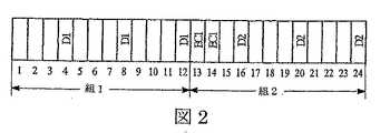
すでに示した定常状態ベクトルPの算出アルゴリズムは、ベルヌーイ・トラフィック・モデルの通信システムに対して導かれた。次の節では、CBRトラフィック・モデルの通信システムにおける定常状態ベクトルPの算出アルゴリズムを導く。このモデルではタイム・スロットは1から無限大まで番号が振られ、主データ・パケットはパケット処理装置にm>1としてt=m,2m,…のタイム・スロットに到着する。主データ・パケットは、m-1の中間のタイム・スロットの間は到着しない。一連のkの主データ・パケットは、一連の(n-k)の主ECパケットと組み合わされて、nの主パケットの組を形作る。m=4、k=3、n=5の場合のパケットの組の例を図2に示す。D1というラベルによって示された第1の組のkの主データ・パケットは、k・mのタイム・スロットの間隔の間、mタイム・スロットごとに1回、パケット処理装置10に到着する。D2というラベルで示される、次の組の主データ・パケットは、次のk・mタイム・スロットの間隔の間に同様な態様で到着する。EC1のラベルで示される第1の組の(n-k)のECパケットは、次の主パケットの組のデータ・パケットの間の空のタイム・スロットに到着する。このスキームの実現可能性を保証するために、ECパケットの数(n-k)は、次のkのデータ・パケットに対する空のタイム・スロットの数を超えないという制限を受ける。これは、
![]()
![]()
と表すことができる。 It can be expressed as.
この到着スキームは、正式には次のように表すことができる。
ここで、
2≦i≦nに対してei=ti-ti-1でありかつ、
ti=主パケットの組のi番目のパケットがパケット処理装置10に到着するタイム・スロット
である。
here,
E i = t i -t i-1 for 2 ≦ i ≦ n, and
ti = the time slot in which the i-th packet in the set of main packets arrives at the
式50のはじめの行は、第1の主データ・パケット以外の、主パケットの組の全てのデータ・パケットに関するものである。第2の行は、最後のデータ・パケットの直後に続く、その組の第1のECパケットに関するものである。第3の行は、次のパケットの組中のデータ・パケットの直後に続かない主ECパケットに関するものである。最後の行は、次のパケットの組のデータ・パケットの直後に続く主ECパケットに関するものである。 The first line of equation 50 relates to all data packets in the set of main packets other than the first main data packet. The second row is for the first EC packet in the set that immediately follows the last data packet. The third row relates to the main EC packet that does not immediately follow the data packet in the next set of packets. The last row is for the main EC packet that immediately follows the data packet of the next set of packets.
以下で導くCBRトラフィック・モデルでは、パケット処理装置10は、主パケットの組の中のはじめのパケット(これは常に主データ・パケットである)を破棄することを仮定する。このパケットが破棄されるとすれば、その確率は、その前の任意のパケットが破棄される確率とは独立である。主パケットの組の中の全てのパケットに対して、主パケットが破棄される可能性は、直前の主パケットの損失確率と直前の主パケットがパケット処理装置10に到着したときのバッファーの使用量を反復的に使用することで計算することができる。この反復的アプローチは式2に示した表現と整合性があり、主パケットが破棄されたときは常に少なくともL-1のバッファー使用量があることを示している。先行する主パケットが到着するとき使用量が少なくともL-1ある状態は、前記の先行するパケットが破棄されず、かつバッファー使用量が0からL-1というより少ないレベルにある場合の状態に比べて、次の主パケットが到着するときに使用量が少なくともL-1ある確率を上昇させる。その結果、パケット処理装置10が先行する主パケットを破棄するか否かという点は、バッファー使用量に関する何らかの情報を与え、これは言い換えると、次の主パケットが破棄される可能性に関する何らかの情報を与える。
In the CBR traffic model derived below, it is assumed that the
2. CBRトラフィック・モデルにおける遷移行列
ベルヌーイ・トラフィック・モデルのすでに述べた遷移行列を、CBRトラフィック・モデルに適合させる。ベルヌーイ分布トラフィックでは、到着過程は到着確率pAにのみ依存するのであるから、全てのタイム・スロットに対して到着過程は統計的に等しい。その結果、すでに述べた遷移T行列は、任意の2の連続するタイム・スロットの確率の間の遷移を適切に記述することができる。CBRトラフィックでは、平均あるいは合成到着確率はpA=1/mで表されるが、CBRトラフィックの到着プロセスは決定的であり、各タイム・スロットは2のクラスの1に分類することができる。タイム・スロットi=1(mod m)では、主パケットが到着し、これらのタイム・スロットに対する遷移行列Fは、式3にpAに1を、qAに0を代入することによって得られる。タイム・スロットi≠1(mod m)では、主パケットが到着せず、これらのタイム・スロットに対する遷移行列Gは、式3にpAに0を、qAに1を代入することによって得られる。遷移行列FとGの積は、連続するタイム・スロットでパケットが到着することを表す。パケットが到着するタイム・スロットは行列Fで表され、パケットが到着しないタイム・スロットは行列Gで表される。
2. Transition matrix in the CBR traffic model The transition matrix already described in the Bernoulli traffic model is adapted to the CBR traffic model. For Bernoulli-distributed traffic, the arrival process depends only on the arrival probability p A , so the arrival process is statistically equal for all time slots. As a result, the previously described transition T matrix can adequately describe transitions between the probabilities of any two consecutive time slots. For CBR traffic, the average or combined arrival probability is expressed as p A = 1 / m, but the arrival process of CBR traffic is deterministic and each time slot can be classified into one of two classes. In time slot i = 1 (mod m), the main packet arrives, transition matrix F to these time slots, one in
3. EC保護のないCBRトラフィック・モデルでのパケット損失確率
EC保護のないCBRトラフィック・モデルの、バッファー使用量に対する定常状態ベクトルπは次のように表される。
![]()
The steady-state vector π with respect to buffer usage for the CBR traffic model without EC protection is expressed as:
![]()
ここで、Tは行列の積の転置を意味する。 Here, T means transposition of matrix product.
式51は行列(FGm-1)T-Iの特異値分解によって解くことができる。ここで、Iは全ての対角成分が1である対角行列であって、一次元の解空間をもち、式
をもちいてπの最終値を決定する。主データ・パケットの損失確率は、式53に示す定常状態ベクトルPを用いるのではなく、定常状態ベクトルπを用いて、式2と同様な式から計算できる。
![]()
![]()
4. EC保護のあるCBRトラフィック・モデルにおけるパケット損失確率
EC保護のないCBRトラフィック・モデルにおけるパケット損失確率を計算する式を導くアプローチを拡張して、EC保護のあるCBRトラフィック・モデルにおける式を導くことができる。これはkのデータ・パケットからなる組の、任意の主データ・パケットがリカバーされない確率を計算することによって、行うことができる。
4). Packet loss probability in CBR traffic model with EC protection
The approach for deriving the equation for calculating the packet loss probability in the CBR traffic model without EC protection can be extended to derive the equation in the CBR traffic model with EC protection. This can be done by calculating the probability that any main data packet of a set of k data packets will not be recovered.
a) 主パケットに対する送信スキームの定義
あるパケットの組の中のnの主パケットのうちのはじめのものが損失する確率は、第1の主データ・パケットが到着するタイム・スロットの直前のタイム・スロットのバッファー使用量の定常状態ベクトルSから決定することができる。この定常状態ベクトルは、ある主パケットの組のkのデータ・パケットが到着する、m・kのタイム・スロットの組に対して導くことができる。主パケットに先行する組の(n-k)のECパケットは、はじめのwのタイム・スロットの間に到着する。ここで、
である。 It is.
m≦wの場合、主パケットの最新の組のデータ・パケットのいくつかもまた、第一のwのタイム・スロットの間に到着する。式49から、w≦m・kであることがわかる。 If m ≦ w, some of the latest set of data packets of the main packet also arrive during the first w time slots. From Equation 49, it can be seen that w ≦ m · k.
さらに次の値を定義する。
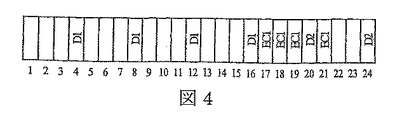
値z-1は、想定したk・mのタイム・スロットのw番目のタイム・スロットと、次の主データ・パケットとの間のタイム・スロットの数に等しい。値yは、データ・パケットがECパケットによって干渉さてれない場合の、mのタイム・スロットの周期または期間の数に等しい。定常状態ベクトルSはこれらの値によって表現できる。式62は、図3に示すようなm-1>wの状態を表しており、ここでは、m=4、k=4、n=6、w=2、u=2、z=2、f=1、y=3である。式63は、図4に示すようなm-1<wの状態を表しており、ここでは、m=4、k=4、n=8、w=5、u=1、z=3、f=1、y=2である。w=m-1に対しては、wは全てのm≧2に対してm-1(mod m)と合同ではないので、式は必要ではない。これは、m=2の場合を検討することでわかる。m=2とすれば、wは偶数であり、m-1(mod m)と合同となることはない。m>2に対しては、反対のことを想定すれば矛盾が生じるので合同ではないことが証明できる。すなわち、次に示す(n-k)の値が存在すると仮定する。
定義より
ここで、0≦d≦m-2であって、この式と式59から、
![]()
![]()
であることがわかる。式61は、左辺は整数であるが、右辺は整数ではないので真とはなり得ない。このことは式59の仮定とは矛盾し、wはm-1(mod m)とは合同とはなり得ないことを示している。 It can be seen that it is. Expression 61 cannot be true because the left side is an integer, but the right side is not an integer. This contradicts the assumption of Equation 59, and indicates that w cannot be congruent with m−1 (mod m).
上に示した到着過程の定義より、定常状態ベクトルSは次のように表すことができる。
πではなくSに対する式52を使用して、式51からから、ベクトルπと同じ方法で、定常状態ベクトルSを決定することができる。 From equation 51, steady state vector S can be determined from equation 51 using equation 52 for S instead of π.
b) ECリカバリー確率
CBRトラフィック・モデルで、ECプロセスによって破棄されたデータ・パケットがリカバリーされる確率は、次に示す5段階のステップによって計算できる。
b) EC recovery probability
In the CBR traffic model, the probability that a data packet discarded by the EC process is recovered can be calculated by the following five steps.
ステップ1:このステップでは、タイム・スロットjの終了時におけるバッファー使用量がgであるという条件を前提として、タイム・スロットj+m-1の終了時におけるバッファー使用量がhである、条件つき確率を決定する。この確率U(m-1,g,h)は次のように表される。
![]()
![]()
ここで、xjは正の整数であり、
![]()
![]()
である。 It is.
この条件つき確率の定義が表していることは、m-1の中間のタイム・スロットの間に主パケットが到着するタイム・スロット(行列Fで表される)と、主データ・パケットが到着しないタイム・スロット(行列Gで表される)があるということである。特に、(j-1)番目のデータ・パケットが到着したタイム・スロットの終了時のバッファー使用量がgであることを前提として、j番目の主パケットが到着する前のタイム・スロットの終了時におけるバッファー使用量がhである条件つき確率R(ej-1,g,h)を、2≦j≦nに対して、計算する。
ここで、
(Fx)g,h=行列Fのx乗のg行h列の要素
(Gy)g,h=行列Gのy乗のg行h列の要素
(FxGy)g,h=行列の積FxGxのg行h列の要素
(F x ) g, h = x-th element of matrix F, g-by-h element
(G y ) g, h = y-th element of matrix G
(F x G y ) g, h = matrix product F x G x g-by-h element
である。項R(ej-1,g,h)は2≦j≦nに対してのみ定義されているのであるから、jがこの範囲に収まらないw、m、q、uのパラメーターの組は、発生することがなく無視されるべき条件を表す。 It is. Since the term R (e j -1, g, h) is defined only for 2 ≦ j ≦ n, the set of parameters for w, m, q, u where j does not fall within this range is Represents a condition that should not be generated and should be ignored.
ステップ2:このステップでは、主パケットが到着するタイム・スロットの直前のタイム・スロットの終了時におけるバッファー使用量がhであるときの、到着する主パケットが破棄されるか場合と、破棄されない場合の条件つき確率を決定する。パケットが破棄されない条件は次の通りである。 Step 2: In this step, when the buffer usage at the end of the time slot immediately before the time slot where the main packet arrives is h, whether the arriving main packet is discarded or not discarded Determine the conditional probability of. The conditions under which the packet is not discarded are as follows.
・ h≦L-2である場合、または、h=L-1かつk=L-2である場合は、到着するパケットは破棄されない。 -If h≤L-2, or if h = L-1 and k = L-2, the arriving packet is not discarded.
・ rを主パケットが到着するタイム・スロットの終了時におけるバッファー使用量として、h=r=L-1である場合、次の条件のいずれか一方が満たされれば、到着するパケットは破棄されない。1)競合パケットが到着せず、パケットがバッファーから確率qCpDで送信される。2)競合パケットが到着したが、それは主パケットの後に到着し、パケットがバッファーから確率
![]()
![]()
で送信される。 Sent by.
・ rを主パケットが到着するタイム・スロットの終了時におけるバッファー使用量として、h=L-1かつr=Lである場合、次の条件のいずれか一方が満たされれば、到着するパケットは破棄されない。1)競合パケットが到着せず、確率qCqDでパケットがバッファーから送信されない。2)競合パケットが到着したが、それは主パケットの後に到着し、確率
![]()
![]()
でパケットがバッファーから送信されない。 Packets are not sent from the buffer.
・ h=Lの場合、到着する主パケットは破棄される。 • When h = L, the incoming main packet is discarded.
最新のタイム・スロットにおいて主パケットが到着し、前のタイム・スロットの終了時のバッファー使用量がhであると仮定して、最新のタイム・スロットの終了時のバッファー使用量がrであり、かつ到着する主パケットが破棄されない条件つき確率は次のように表すことができる。
同様に、最新のタイム・スロットにおいて主パケットが到着し、前のタイム・スロットの終了時のバッファー使用量がhであると仮定して、最新のタイム・スロットの終了時のバッファー使用量がrであり、到着する主パケットが破棄される条件つき確率は次の様に表すことができる。
ステップ3:このステップでは、ある組の中の(j-1)番目の主パケットが到着するタイム・スロットの終了時のバッファー使用量がgであるとして、その組の主パケットのj番目のパケットが到着するタイム・スロットの終了時のバッファー使用量がrであり、かつ、j番目のパケットが破棄されない場合の、条件つき確率を決定する。この条件つき確率は次のように表すことができる。
同様に、ある組の中の(j-1)番目の主パケットが到着するタイム・スロットの終了時のバッファー使用量がgであるとして、その組の主パケットのj番目のパケットが到着するタイム・スロットの終了時のバッファー使用量がrであり、かつ、j番目のパケットが破棄される場合の条件つき確率は、次のように表すことができる。
ステップ4:このステップでは、1≦a≦nかつ0≦b≦aとして、主パケットの組のはじめのaのパケットのうち、bのパケットが破棄される条件つき確率M(a,b,d)と、そのa番目のパケットが到着するタイム・スロットの終了時のバッファー使用量がdに等しい条件つき確率を決定する。a=1に対しては、確率M(a,b,d)は、すでに述べた式62および63に定義されたベクトルSの関数として表現することができる。a>1に対しては、確率M(a,b,d)は、次の式に示すように、A(k,g,j)とB(k,g,j)を用いて再帰的に定義することができる。
ステップ5:このステップでは、kの主パケットのうちνが破棄され、はじめのaのECパケットのうちbが破棄され、a番目のECパケットが到着するタイム・スロットの終了時にバッファー使用量がdに等しい確率D(a,b,d,ν)を求める。ここで、1≦a≦n-k、0≦b≦a、0≦ν≦kである。a=1に対して、確率D(a,b,d,ν)はM(k,ν,j)、A(j,d,k)、B(j,d,k)の関数として表すことができる。a>1に対しては、確率D(a,b,d,ν)はD(a-1,b,d,ν)、A(j,d,k)、B(j,d,k)を用いて、次の式に示すように、再帰的に定義することができる。
kの主データ・パケットのうちνが破棄され、(n-k)のECパケットのうちbが破棄される確率H(ν,b)は次のように表すことができる。
ECプロセスによってリカバリーされるデータ・パケットの数の平均値または期待値Erecは次のように表すことができる。
ここで、
である。 It is.
F. CBRトラフィク・モデルにおける近似アルゴリズム
Erecの近似値のみを計算をするアルゴリズムは、ベルヌーイ・トラフィック・モデルにおいては通常不要である。なぜなら、式48に示すようにErecを厳密に算出するには、計算複雑性がO(1)である、式42、k=L-1に対する式43、および式44を計算し、計算複雑性がO(nk)である式46が必要であるからである。Erecを計算するこのアルゴリズムの全体にわたる計算複雑性は、O(nk)である。この複雑性を表す数は、全ての必要な二項係数が予め計算され、引き続いて使用することができるように格納されていることを想定している。Erecを計算するのに必要な時間は、L=400の場合、Cプログラミング言語を用いて実装し、カリフォルニア州サンタ・クララのIntel社から供給されている3.4GHzのペンティアム(R)マイクロプロセッサーを用いれば、1msec未満である。これは、多くの実施例でのリアル・タイム性の要求に十分合致する速度である。
F. Approximation algorithm in CBR traffic model
An algorithm that calculates only the approximate value of E rec is usually unnecessary in the Bernoulli traffic model. Because, in order to calculate E rec exactly as shown in Expression 48, the calculation complexity is O (1), the expression 42, the expression 43 and the expression 44 for k = L−1 are calculated, and the calculation complexity is calculated. This is because the formula 46 having sex O (nk) is necessary. The overall computational complexity of this algorithm for calculating E rec is O (nk). This complexity number assumes that all necessary binomial coefficients are pre-calculated and stored for subsequent use. The time required to calculate E rec is implemented using the C programming language when L = 400, and a 3.4 GHz Pentium (R) microprocessor supplied by Intel, Santa Clara, California. If used, it is less than 1 msec. This is a speed that well meets the real-time requirements of many embodiments.
残念ながら、CBRトラフィック・モデルでは、Erecの近似値を求めるアルゴリズムが必要である。なぜなら、厳密アルゴリズムの計算複雑性が極めて高いからである。 Unfortunately, the CBR traffic model requires an algorithm that approximates E rec . This is because the computational complexity of the exact algorithm is extremely high.
1. 厳密アルゴリズムの複雑性
前記の5ステップのアルゴリズムから導かれた式71は、近似を用いることなく期待値Erec計算するのであるから、ここでは厳密アルゴリズムと呼ぶ。第1ステップでは行列m・kの積を行った上で、行列(L+1)x(L+1)の特異値分解を計算する。これらの演算の計算複雑性はO(mkL3)である。第2ステップと第3ステップを実行するために必要な演算の計算複雑性は、無視することができる。確率M(a,b,d)を計算する第4ステップの演算の計算複雑性はO(k2L)である。確率D(a,b,dν)を計算する第5ステップの演算の計算複雑性はO((n-k)2kL2)である。5段階のアルゴリズムの全体としての計算複雑性は、およそO(mkL 3 +k 2 L+((n-k) 2 kL 2 ))である。しかしながら、現実的な実装では、バッファーの大きさLは、n,kの値よりも1桁または2桁大きいと思われるのであるから、このアルゴリズムの全体としての複雑性はおよそO(mkL3)である。
1. Complexity of Exact Algorithm Since Expression 71 derived from the above five-step algorithm calculates the expected value E rec without using approximation, it is called an exact algorithm here. In the first step, the product of the matrix m · k is performed, and then the singular value decomposition of the matrix (L + 1) x (L + 1) is calculated. The computational complexity of these operations is O (mkL 3 ). The computational complexity of the operations required to perform the second and third steps can be ignored. The computational complexity of the operation in the fourth step for calculating the probability M (a, b, d) is O (k 2 L). The computational complexity of the fifth step of calculating the probability D (a, b, dν) is O ((nk) 2 kL 2 ). The overall computational complexity of the five-stage algorithm is approximately O (mkL 3 + k 2 L + ((nk) 2 kL 2 )) . However, in a practical implementation, the buffer size L is likely to be one or two orders of magnitude greater than the value of n, k, so the overall complexity of this algorithm is approximately O (mkL 3 ) It is.
表1の要素は、5ステップのアルゴリズムをCプログラミング言語で書いた実装の例を、3.4GHzペンティアム・プロセッサー上で実行した場合の、Erecを計算するために必要な総時間を示している。第1ステップの特異値分解には、ケンブリッジ大学出版局1992年、Press他著「Numerical Recipes in C++; The Art of Scientific Computing(第2版)」に記載の、「svdcmp」ルーチンを用いた。
典型的なマルチメディア無線ネットワークでは、パケット処理装置10は市場に流通しているIEEE802.11に基づいたワイヤレス・アクセス・ポイント(AP)として実装され、典型的には300またはそれ以上のパケットにあたるバッファーの格納容量がある。表1の要素がによれば、このようなAPでは、前記の典型的な実装を用いて期待値Erecを計算するのに必要な時間は、少なくとも623msecであるということである。残念ながら、多くのマルチメディア・アプリケーションに対して、ECパラメーター(n,k)をリアル・タイムに適用するためには、少なくとも1桁少ない時間の間にこの計算を行わなければならない。つぎに、かなり少ない時間でErecの概算値を計算する、より複雑性の少ないアルゴリズムを次に導く。
In a typical multimedia wireless network, the
2.崩壊状態モデル
前記の5ステップのアルゴリズムの目的は、ECリカバリー後の情報の損失を最小化するECパラメーター(n,k)を決定することである。このアルゴリズムを用いて計算をする必要があるのは、バッファー・オーバーフローのためにパケット処理装置10が1または複数のパケットを破棄してパケット損失が発生した場合のみである。バッファー・オーバーフローが発生するのは、バッファー使用量がLであるか、またはそれに近い値であり、パケット処理装置10における競合パケットと主パケット両者の累積的な到着頻度が、その装置がパケットをバッファーから送信する頻度に比べて高い場合である。言葉を換えれば、kがLにきわめて近い例外的な場合を除いて、全てのkに対して、定常状態ベクトルSの成分Skは0か、または0に近いということである。
2. Collapsed state model The purpose of the five-step algorithm is to determine EC parameters (n, k) that minimize the loss of information after EC recovery. The calculation using this algorithm is required only when the
数値実験によって、これらの予想を確認する。図5ないし7に、異なる競合トラフィック頻度pCに対する定常状態確率Skの分布を示す。この3の例において、m=4、n=6、k=5、pD=0.8である。到着頻度の合計pA+pCがpDに等しいとき、このモデルは平衡状態になり、これはpC=0.5の時に生じる。図5に示す例では、pC=0.52であり、これは、平衡頻度に比べてわずかに大きい。この図に示すように、kが増大するに従って、定常状態確率Skは急速に増大するが、定常状態確率が0.01より大きくなるのは、k>95の場合だけである。pCが増大して、到着頻度の合計pA+pCが転送頻度pDより大きい場合、例えば、図6及び7にそれぞれ示すようにpC=0.6およびpC=0.66のような場合であっても、kがLにきわめて近い場合でない限り、定常状態確率Skは、0であるか0に近い。 These predictions are confirmed by numerical experiments. 5 to 7 show the distribution of steady state probabilities S k for different competing traffic frequencies p C. In these three examples, m = 4, n = 6, k = 5, and p D = 0.8. The model is in equilibrium when the total arrival frequency p A + p C is equal to p D , which occurs when p C = 0.5. In the example shown in FIG. 5, p C = 0.52, which is slightly larger than the equilibrium frequency. As shown in this figure, according to k increases, although the steady-state probability S k increases rapidly, the steady state probability is greater than 0.01 is only the case of k> 95. When p C increases and the total arrival frequency p A + p C is larger than the transfer frequency p D , for example, when p C = 0.6 and p C = 0.66 as shown in FIGS. Even so, unless k is very close to L, the steady state probability S k is 0 or close to 0.
この挙動は、よい近似アルゴリズムの開発に使用できる。定常状態確率Skが0あるいは0に近いトラフィック・モデルのいかなる状態も、システムに対して顕著な影響を与えない。なぜなら、システムは原則としてこの状態にならないからである。図5ないし7に示す例では、Sk≒0である全ての状況のうち大部分は、定常状態モデルの動的変化に影響をほとんど与えないか、全く与えない。結果として、これらの状態を定常状態ベクトルSの計算を行うときに無視したとしても、計算結果に大きな変化を与えないし、Erecの計算値に大きな変化を与えない。 This behavior can be used to develop good approximation algorithms. Any state of the traffic model with a steady state probability Sk of 0 or close to 0 has no significant effect on the system. This is because the system does not enter this state in principle. In the examples shown in FIGS. 5-7, the majority of all situations where S k ≈0 have little or no effect on the dynamic change of the steady state model. As a result, even if these states are ignored when calculating the steady state vector S, the calculation result is not significantly changed, and the calculated value of E rec is not significantly changed.
この観察結果に基づけば、Sk>εであって、εを小さい閾値としたときの、定常状態kのみに対するErecを計算する近似アルゴリズムを導くことができる。この近似アルゴリズムは、Sk>εである全ての状態kが個々のベクトル成分Ck=Sk+L0によって表され、Sk≧εである他の全ての状態kは単一状態C0に崩壊する、崩壊した状態ベクトルCを使用する。L0をバッファー使用量の閾値として、k≦L0でSk≦εが前提とされている。結果として、崩壊した状態ベクトルCは、0≦k≦L-L0に対して、L-L0+1の成分Ckを持つにすぎない。 Based on this observation result, it is possible to derive an approximation algorithm for calculating E rec for only the steady state k when S k > ε and ε is a small threshold. This approximation algorithm is such that all states k with S k > ε are represented by individual vector components C k = S k + L0 and all other states k with S k ≧ ε are in a single state C 0 . Use collapsed state vector C. Assuming that L 0 is the buffer usage threshold, k ≦ L 0 and S k ≦ ε. As a result, the collapsed state vector C has only LL 0 +1 component C k for 0 ≦ k ≦ LL 0 .
式3の遷移行列を、Lにかえて値L-L0を用いて再定義することによって、L+1の成分を持つ定常状態ベクトルSは、L-L0+1のみの成分を持つ崩壊した状態ベクトルCによって、近似的に表すことができる。0≦a,b≦L-L0に対する、状態CaとCbの間の遷移確率を、Ta+L0,b+L0と定義する。この遷移行列は、a,b>0であれば、バッファー使用量の変化を正確に表しているが、a=0であるかまたはb=0である場合には、バッファー使用量の動的変化を近似的に表すにすぎない。この近似は、閾値εに十分に小さな値を選べば、1≦k≦L-L0のときCkの計算の正確性に顕著な影響を与えない。なぜなら、崩壊した状態C0は、確率がεL0という、きわめてまれな頻度でしか発生しないからである。正確にいえば、差の絶対値|Ck-Ck+L0|は1≦k≦L-L0において極めて小さいことが期待できるのである。
By redefining the transition matrix of
崩壊した状態ベクトルCは、式62または63のいずれかに特異値分解を適用し、すでに述べたようにベクトルπに換えてベクトルCを使った式52を用いて前記結果を正規化することによって、計算することができる。ベクトルCを計算した後、Erecの近似値は、ベクトルSではなくベクトルCを用いて式71から計算できる。図5ないし7の例から、値L0は値Lに近いことが予想できるので、計算複雑性をO(mkL3)からO(mk(L-L0)3)に減少させることができるということが予想できる。表1でバッファーの大きさLに換えて値L-L0を使用して、L0が充分にLに近い場合、この典型的な実装の実行時間を1桁またはそれ以上減少させることがわかる。L0の値は、多くのマルチメディア・アプリケーションのリアル・タイム性の要求を満たすような、近似アルゴリズムの実装ができる値が選ばれる。 The collapsed state vector C is obtained by applying singular value decomposition to either Equation 62 or 63 and normalizing the result using Equation 52 using Vector C instead of Vector π as already mentioned. Can be calculated. After calculating vector C, the approximate value of E rec can be calculated from equation 71 using vector C instead of vector S. From the examples of FIGS. 5 to 7, since the value L 0 can be expected to be close to the value L, it is possible to reduce the computational complexity from O (mkL 3 ) to O (mk (LL 0 ) 3 ). I can expect. Using the value LL 0 instead of the buffer size L in Table 1, it can be seen that if L 0 is sufficiently close to L, the execution time of this exemplary implementation is reduced by an order of magnitude or more. The value of L 0 is selected so that an approximation algorithm can be implemented that satisfies the real-time requirements of many multimedia applications.
近似アルゴリズムを使用する前に、L0を決定しなければならない。数値シミュレーションによれば、μ=0.1として、pA+pC>pD+μである場合は常に、近似アルゴリズムの正確性を顕著に下げることなく、L0=10を選ぶことができる。式71から計算されたErecの正確な値とともに、近似アルゴリズムに使用するために、μの異なる値に対して適切であるL0の値の組を予め計算しておくことができる。これは、L0のどの値を使用すれば近似アルゴリズムがErecを見積もる上で正確性を維持できるのかを決定するためである。 Before using the approximation algorithm, L 0 must be determined. According to the numerical simulation, whenever μ = 0.1 and p A + p C > p D + μ, L 0 = 10 can be selected without significantly reducing the accuracy of the approximation algorithm. Along with the exact value of E rec calculated from Equation 71, a set of L 0 values that are appropriate for different values of μ can be pre-calculated for use in the approximation algorithm. This is to determine which value of L 0 can be used to maintain accuracy in estimating the Erec by the approximation algorithm.
この崩壊した定常状態近似技術は、原則としていかなるトラフィック・モデルに対しても、計算複雑性を減少したアルゴズムを得るために使用することができる。 This collapsed steady state approximation technique can in principle be used for any traffic model to obtain an algorithm with reduced computational complexity.
G 実施例
前記の技術を使用して、パケット通信システムにおける様々な種類の実施例を実装するアルゴリズムを導くことができる。
G Embodiments The techniques described above can be used to derive algorithms that implement various types of embodiments in packet communication systems.
ある実施例では、前記のアルゴリズムを使用して、パラメーターpA、pC、pD、LおよびECパラメーター(n,k)が与えられたときの、ECリカバリー後の主パケットの損失確率を計算する。 In one embodiment, the above algorithm is used to calculate the loss probability of the main packet after EC recovery given the parameters p A , p C , p D , L and EC parameters (n, k) To do.
ある実施例では、ECパラメーター(n,k)を順応させて、ECリカバリー後の主データ・パケットの損失を最小化する。これを実現する一つの方法は、検討中の通信システムに対して、全ての適切なパラメーター値の組(n,k)を、はじめに決定しておくことである。通信経路帯域幅および最大許容遅延などのこのシステムに関する制約は、ECパラメーターの選択に関しても制約となる。帯域幅に関する制限は比率φに関する制限となり、遅延に関する制限は、パラメーターnに関する制限となる。最大限許容可能な遅延の総量と帯域幅を規定した上で、これらの要求を満たすECパラメーターの組(n,k)を全て特定することによって、適切なパラメーターの値の組(n,k)を決定することができる。上に導いたアルゴリズムを、パラメーターpA、pC、pD、Lおよび、適切なECパラメーターの値の全部又は一部に適用することによって、関連する損失確率を計算することができる。損失確率を最も下げるECパラメータの値(n,k)が、パラメーターの最適な組として選択される。 In one embodiment, EC parameters (n, k) are adapted to minimize loss of main data packets after EC recovery. One way to achieve this is to first determine all appropriate parameter value pairs (n, k) for the communication system under consideration. Constraints on this system such as communication path bandwidth and maximum allowable delay are also constraints on the selection of EC parameters. The limit on bandwidth is a limit on ratio φ, and the limit on delay is a limit on parameter n. By specifying all the EC parameter pairs (n, k) that meet these requirements, specifying the maximum allowable delay amount and bandwidth, the appropriate parameter value set (n, k) Can be determined. By applying the algorithm derived above to all or part of the values of the parameters p A , p C , p D , L and the appropriate EC parameters, the associated loss probabilities can be calculated. The value (n, k) of the EC parameter that minimizes the loss probability is selected as the optimal set of parameters.
他の実施例は、データ源2が主パケットを送信する最適な頻度を決定するために使用される。この実施例では、ECパラメーター(n,k)の値を選択し、異なるパケット到着頻度pAに対して前記のアルゴリズムを適用して、関連する損失確率を計算する。多くの場合、実施上の配慮から、考え得る頻度に関して制限がある。損失確率を最小化する頻度は、データ源の最適送信頻度として設定される。
Another embodiment is used to determine the optimal frequency at which
別の方法として、導かれたアルゴリズムを、ECパラメーター(n,k)とパケット到着頻度の両者の一連の値に適用して、損失確率を最小化する設定を決定する。 Alternatively, the derived algorithm is applied to a series of values for both the EC parameter (n, k) and the packet arrival frequency to determine a setting that minimizes the loss probability.
さらに別の実施例では、パラメーターpA、pD、L、ECパラメーター(n,k)、および、ECリカバリー後の主パケットを損失する割合を与えて、競合パケットが到着する確率を表すpCを計算する。前記のアプリケーションは、パラメーターpA、pC、pD、Lの値は既知のものであることを想定している。pCの値が未知である場合、EC保護がないときはpCの値はパラメーターpA、pD、Ploss、およびLから得ることができ、EC保護があるときは、pA、n、k、pD、Eloss、およびLから得ることができる。例えば、データ源2において、pCを計算する反復処理が実装されてもよい。この処理は、データ源2からpA、n、およびkの値を得ることができ、レシーバー20からpD、および、PlossまたはElossの値を得ることができる。Lの値は通常はア・プリオリにわかっているのであるが、仮にわかっていなかった場合にはパケット処理装置10から得ることができる。反復を行う方法は、次のパラグラフで述べる。このプロセスで計算されるpcの値は、すでに述べたアルゴリズムの入力パラメーターとして使うなど、他の実施例において使用することもできる。
In yet another embodiment, the parameters p A , p D , L, EC parameters (n, k), and p C representing the probability of a competing packet arriving given the percentage of loss of the main packet after EC recovery. Calculate The application assumes that the values of the parameters p A , p C , p D , L are known. If the value of p C is unknown, the value of p C can be obtained from the parameters p A , p D , P loss , and L when there is no EC protection, and p A , n when there is EC protection , K, p D , E loss , and L. For example, in the
EC保護がない場合、ベルヌーイ・トラフィック・システムのpcの値は、式2および式42ないし44に定められた関係から決定することができる。CBRトラフィック・モデルでは、この値は、式2に定められた関係と、式53に関連して述べた前記の技術から決定することができる。いずれのタイプのシステムであっても、これらの式によって定められた関係から、pCとPlossの間の関係は単調な一対一写像となる。この写像の特徴を使用して、pcの値に収束する反復的二分探索法によってpcを決定することができる。
In the absence of EC protection, the Bernoulli traffic system pc value can be determined from the relationships defined in
EC保護がある場合、ベルヌーイ・トラフィック・システムのpcの値は、式2および48に定められた関係から決定することができる。CBRトラフィック・モデルでは、その値は、式2および71に定められた関係から決定することができる。いずれのタイプのシステムであっても、これらの式によって定められた関係から、pCとErecの間の関係は単調な一対一写像となる。この写像の特徴を使用して、pcの値に収束する反復的二分探索法によってpcを決定することができる。
With EC protection, the value of pc for Bernoulli traffic system can be determined from the relationship defined in
多くの実装では、nとkの適切な選択は、帯域幅と遅延の要求によって制限を受ける。前のパラグラフで記載したアルゴリズムを使用して、全ての適切なnとkの組の中から、ECリカバリー後の損失確率を最小化するECパラメーター(n,k)を発見することができる。pcの値は前記の方法で決定され、nとkの全ての適切な値に対する探索が行われて、最適値を見つける。 In many implementations, the proper choice of n and k is limited by bandwidth and delay requirements. Using the algorithm described in the previous paragraph, an EC parameter (n, k) that minimizes the loss probability after EC recovery can be found out of all the appropriate n and k pairs. The value of pc is determined in the manner described above, and a search is performed for all appropriate values of n and k to find the optimal value.
H実装
図1によれば、通信経路3、5、11、21、および22は、金属線を経由する電気信号、光ファイバーを経由する光信号、空間を経由する無線周波数(RF)放射のような、原則として任意の技術とメディアによって実装することができる。本発明は、図1に示すような、通信経路11が無線RF経路であり、他の通信経路が電気又は光経路である通信システムの場合に、有利に使用することができる。
H implementation According to FIG. 1,
本発明の様々な実施態様を実施するのに必要な機能は、個別の論理要素、集積回路、1または複数のASIC、ないしプログラム制御プロセッサーを含む様々な方法によって実装することができる。これらの要素が実装される態様は、本発明にとって重要ではない。 The functions required to implement various embodiments of the present invention can be implemented by various methods including individual logic elements, integrated circuits, one or more ASICs, or a program control processor. The manner in which these elements are implemented is not critical to the present invention.
本発明をソフトウェアとして実装した場合、超音波領域から紫外線領域を含む周波数帯域のベースバンドあるいは変調された通信経路、または、磁気テープ、磁気カード、磁気ディスク、光カード、光ディスク、紙を含む媒体上の可読性のあるマークを含む、原則として任意の記録技術を用いた情報を運ぶ記憶媒体のような、様々な種類の機械可読媒体に搭載することができる。 When the present invention is implemented as software, a baseband or modulated communication path in a frequency band including an ultrasonic region to an ultraviolet region, or a medium including a magnetic tape, a magnetic card, a magnetic disk, an optical card, an optical disk, and paper. Can be mounted on various types of machine-readable media, such as storage media that carry information using, in principle, any recording technique, including any readable mark.
Claims (12)
パケットの組の形にアレンジされた情報を運ぶ源信号を供給する第1のデータ源と、
前記源信号を受信し、バッファー・サイズの大きさを持つバッファーに前記パケットの組の中の少なくともいくつかのパケットに対応する情報を格納し、前記バッファーに格納されていた少なくともいくつかのパケットの情報を有するパケットを含む出力信号を送信するパケット処理装置であって、前記パケットの組の中の少なくともいくつかのパケットに対応する情報が、前記バッファーが一杯であることを原因とする損失のために前記出力信号から削除されている、パケット処理装置と、
前記出力信号のパケットの少なくともいくつかのパケットを受信するレシーバーと
を含み、当該方法は、
(a)前記バッファー・サイズと、一定時間間隔の間に、前記パケット処理装置によって任意の競合データ源からの競合パケットが受信される干渉確率と、前記バッファーが空でない時に前記一定時間間隔の間に前記パケット処理装置がパケットの送信に成功する送信確率とを表すパラメーターを運ぶ1または複数の信号を受信するステップと、
(b)前記パラメーターから損失確率の1または複数の量を導くステップであって、各量はデータ・パケット中の情報が損失する確率を表し、損失確率の各量は前記バッファーが一杯であることを原因とする損失を計算に入れるプロセスから導かれ、
(1)前記プロセスは、ベルヌーイ過程の確率分布の確率過程に従って前記原信号のパケットが前記パケット処理装置に到着するモデルの解決法を表現し、前記バッファー・サイズとは独立の計算複雑性をもち、0から1の間の値をとる第1の到着確率と前記送信確率と前記干渉確率の全ての値に対して、前記損失確率は0から1の間の値をとるか、または、
(2)前記プロセスは、前記源信号中のパケットが決定的過程に従って前記パケット処理装置に到着するモデルの解決法を表すか
のいずれかである、ステップと、
(c)前記パケット処理装置の前記バッファーが一杯であるためにデータ・パケット中の情報が損失する可能性を引き下げるために前記第1のデータ源の動作を順応させるステップであって、
前記パケットの組が、第1数のデータ・パケットと第2数のエラー訂正パケットとを含み、前記レシーバーが前記受信したパケットにエラー訂正処理を適用して、破損あるいは損失した情報をリカバリーし、前記パラメーターは、前記第1および前記第2数、ならびに前記第1のデータ源からのパケットが前記一定時間間隔内に前記パケット処理装置によって受信される第2の到着確率をも表し、データ・パケット中の情報が失われエラー訂正処理によってリカバリーされない確率を表す損失確率の量が、前記パラメーターから導かれ、前記損失確率の量に対応して前記第1数または前記第2数を変更するように前記第1のデータ源が動作するか、
または、
複数の到着確率のそれぞれに対応する損失確率の各量は前記パラメーターから導かれ、各到着確率は、前記第1のデータ源からのパケットが時間間隔内に前記パケット処理装置によって受信される確率を表し、複数の損失確率の中で最小の損失確率を導く前記到着確率を選択し、前記パケット処理装置が選択された到着確率をより厳密に反映するようにパケットを受信するよう前記第1のデータ源の動作を変更することによって、前記第1のデータ源の動作が順応させられるか、
のいずれかであるステップとを含む方法。A method for controlling the supply of packets in a communication system, the communication system comprising:
A first data source that provides a source signal carrying information arranged in packet sets;
Receiving the source signal, storing information corresponding to at least some packets in the set of packets in a buffer having a size of a buffer size, and storing at least some of the packets stored in the buffer; a packet processing device for transmitting an output signal containing a packet having the information, information corresponding to at least some of the packets in the set of packets, because the losses caused by that the buffer is full A packet processing device that has been deleted from the output signal;
Look including a receiver for receiving at least some of the packets of the packet of the output signal, the method comprising
(A) and the buffer size, during a predetermined time interval, an interference probability that a competing packet from any competing data source is received by the packet processing device during said predetermined time interval when the buffer is not empty a step of the packet processing device receives one or more signals that carry parameters representing the transmission probability of successful transmission of a packet,
And (b) directing one or more of the amount of loss probability from the parameters, it each quantity represents a probability of loss of information in the data packets, each amount of loss probability is the buffer is full derived from the process to account for the losses caused by,
(1) The process expresses a solution of a model in which the original signal packet arrives at the packet processing device according to the probability process of the Bernoulli process probability distribution, and has computational complexity independent of the buffer size. The loss probability takes a value between 0 and 1 for all values of the first arrival probability , the transmission probability and the interference probability taking a value between 0 and 1, or
(2) the process is either representing a model solution where packets in the source signal arrive at the packet processing device according to a deterministic process; and
(C) adapting the operation of the first data source to reduce the possibility of losing information in the data packet because the buffer of the packet processing device is full ,
Set of packets comprises a first number of data packets and error correction packets of the second number applies error correction processing to packets the receiver the received, the broken Sun-Rui information lost recover the parameter represents the first and the second number, and also the second arrival probability that a packet from the first data source is received by the packet processing apparatus in the predetermined time interval, A loss probability amount representing the probability that information in the data packet is lost and not recovered by the error correction process is derived from the parameter, and the first number or the second number is changed according to the loss probability amount. whether the first data source is operable to,
Or
Each amount of loss probability corresponding to each of a plurality of arrival probabilities is derived from the parameter , and each arrival probability is a probability that a packet from the first data source is received by the packet processing device within a time interval. The first data to represent, select the arrival probability that leads to a minimum loss probability among a plurality of loss probabilities , and receive the packet so that the packet processing device more accurately reflects the selected arrival probability Whether the operation of the first data source is adapted by changing the operation of the source;
And a step that is any of the following.
前記干渉確率が、確率的過程に従って前記パケット処理装置に到着する競合パケットの第2の確率分布に一致する、請求項1に記載の方法。The arrival probability, matches according deterministic process to a first probability distribution of packets in the source signal arriving at the packet processing device,
The method of claim 1, wherein the interference probability matches a second probability distribution of competing packets arriving at the packet processing device according to a stochastic process.
前記プロセスは、近似することなく損失確率の量を導き、前記第2数と第3数の積に比例する計算複雑性をもち、該第3数は前記第1数と前記第2数の和に等しい、請求項1に記載の方法。The arrival probability matches a first probability distribution of packets in the source signal arriving at the packet processing device according to a Bernoulli process;
The process leads to the amount of loss probability without approximation, the second number and have a computational complexity that is proportional to the third number of the product, the third number is the sum of the second number and the first number The method of claim 1, wherein
前記源信号を受信し、バッファー・サイズの大きさを持つバッファーに前記パケットの組の中の前記パケットの少なくともいくつかのパケットに対応する情報を格納し、前記バッファーに格納されていた少なくともいくつかのパケットの情報を有するパケットを含む出力信号を送信するパケット処理装置であって、前記パケットの組の中の少なくともいくつかのパケットに対応する情報が、前記バッファーが一杯であることを原因とする損失のために前記出力信号から削除されている、パケット処理装置と、
前記出力信号の前記パケットの少なくともいくつかのパケットを受信するレシーバーと を含む通信システムであって、1又は複数の前記第1のデータ源と、前記パケット処理装置と、前記レシーバーとが、請求項1ないし8のいずれか1項に記載の方法を実行する回路を有する、通信システム。A first data source that provides a source signal carrying information arranged in packet sets;
Receiving the source signal, storing information corresponding to at least some of the packets in the set of packets in a buffer having a buffer size, and storing at least some of the packets stored in the buffer A packet processing apparatus for transmitting an output signal including a packet having information on a plurality of packets, the information corresponding to at least some of the packets in the set of packets caused by the buffer being full A packet processing device being deleted from the output signal due to loss;
A communication system comprising: a receiver that receives at least some of the packets of the output signal, wherein the one or more first data sources, the packet processing device, and the receiver are: 1 to have a circuitry to run the method according to any one of 8, a communication system.
前記レシーバーがエラー訂正プロセスを前記受信したパケットに適用して、破損したあるいは失われた情報をリカバリーする、請求項9に記載の通信システム。The set of packets includes a first number of data packets and a second number of error correction packets;
The communication system according to claim 9, wherein the receiver applies an error correction process to the received packet to recover corrupted or lost information.
パケットの組の形でアレンジされた情報を運ぶ源信号を提供する第1のデータ源と、
前記源信号を受信し、バッファー・サイズの大きさを持つバッファーに前記パケットの組の中の少なくともいくつかのパケットに対応する情報を格納し、前記バッファーに格納されていた少なくともいくつかのパケットの情報を有するパケットを含む出力信号を送信するパケット処理装置であって、前記パケットの組の中のパケットの少なくともいくつかに対応する情報が前記バッファーが一杯であることを原因とするに損失のために前記出力信号から削除されている、パケット処理装置と、
前記出力信号のパケットのうち少なくともいくつかを受信するレシーバーと
を含む、記録媒体。 A recording medium for recording a program of instructions for causing an apparatus to execute the method according to any one of claims 1 to 8 for controlling the provision of packets in a communication system , wherein the communication system includes:
A first data source providing a source signal carrying information arranged in packet sets;
Receiving the source signal, storing information corresponding to at least some packets in the set of packets in a buffer having a size of a buffer size, and storing at least some of the packets stored in the buffer; A packet processing device for transmitting an output signal including a packet having information, the information corresponding to at least some of the packets in the set of packets due to loss due to the buffer being full A packet processing device that has been deleted from the output signal;
And a receiver for receiving at least some of the packets of said output signals, a recording medium.
前記レシーバーは前記受信したパケットにエラー訂正処理を適用して破損したあるいは失われた情報をリカバリーする、請求項11に記載の記録媒体。The set of packets includes a first number of data packets and a second number of error correction packets;
The recording medium according to claim 11, wherein the receiver recovers damaged or lost information by applying error correction processing to the received packet.
Applications Claiming Priority (3)
| Application Number | Priority Date | Filing Date | Title |
|---|---|---|---|
| US11/174,005 | 2005-06-30 | ||
| US11/174,005 US7447977B2 (en) | 2005-06-30 | 2005-06-30 | Method and system for optimizing forward error correction of multimedia streaming over wireless networks |
| PCT/US2006/020861 WO2007005160A1 (en) | 2005-06-30 | 2006-05-26 | Method and system for optimizing forward error correction of multimedia streaming over wireless networks |
Publications (3)
| Publication Number | Publication Date |
|---|---|
| JP2008545356A JP2008545356A (en) | 2008-12-11 |
| JP2008545356A5 JP2008545356A5 (en) | 2009-07-02 |
| JP5048664B2 true JP5048664B2 (en) | 2012-10-17 |
Family
ID=36942296
Family Applications (1)
| Application Number | Title | Priority Date | Filing Date |
|---|---|---|---|
| JP2008520239A Expired - Fee Related JP5048664B2 (en) | 2005-06-30 | 2006-05-26 | Method and communication system for controlling the supply of packets |
Country Status (10)
| Country | Link |
|---|---|
| US (1) | US7447977B2 (en) |
| EP (1) | EP1900134B1 (en) |
| JP (1) | JP5048664B2 (en) |
| KR (1) | KR101246783B1 (en) |
| CN (1) | CN101273570B (en) |
| AT (1) | ATE492081T1 (en) |
| DE (1) | DE602006018925D1 (en) |
| MY (1) | MY144828A (en) |
| TW (1) | TWI392286B (en) |
| WO (1) | WO2007005160A1 (en) |
Families Citing this family (28)
| Publication number | Priority date | Publication date | Assignee | Title |
|---|---|---|---|---|
| CA2364425A1 (en) * | 2001-12-05 | 2003-06-05 | Algorithmics International Corp. | A system for calculation of operational risk capital |
| US7533324B2 (en) * | 2004-09-22 | 2009-05-12 | Kencast, Inc. | System, method and apparatus for FEC encoding and decoding |
| US7739580B1 (en) | 2005-02-17 | 2010-06-15 | Kencast, Inc. | System, method and apparatus for reducing blockage losses on information distribution networks |
| US8223643B1 (en) * | 2005-09-06 | 2012-07-17 | Kencast, Inc. | Method for packet-level FEC encoding a stream of source packets using shifted interleaving |
| EP2249528B1 (en) | 2006-04-13 | 2013-06-12 | Dolby Laboratories Licensing Corporation | Estimating wireless processing device queue length and estimating signal reception quality in a wireless network |
| CN101529771B (en) * | 2006-08-17 | 2013-04-24 | 杜比实验室特许公司 | Transient analysis of packet queuing loss in a broadcast network |
| US8707139B2 (en) | 2006-10-18 | 2014-04-22 | Kencast, Inc. | Systems, methods, apparatus, and computer program products for providing forward error correction with low latency |
| US8046656B2 (en) * | 2006-10-31 | 2011-10-25 | Hewlett-Packard Development Company, L.P. | Rendering and correcting data |
| US20080239953A1 (en) * | 2007-03-28 | 2008-10-02 | Honeywell International, Inc. | Method and apparatus for minimizing congestion in gateways |
| US20080239948A1 (en) * | 2007-03-28 | 2008-10-02 | Honeywell International, Inc. | Speculative congestion control system and cross-layer architecture for use in lossy computer networks |
| US7930616B2 (en) * | 2007-04-12 | 2011-04-19 | Cisco Technology, Inc. | Variable forward error correction for optical communication links |
| US9106800B2 (en) * | 2007-08-31 | 2015-08-11 | At&T Intellectual Property I, L.P. | System and method of monitoring video data packet delivery |
| US8418034B2 (en) | 2008-02-08 | 2013-04-09 | Kencast, Inc. | Systems, methods, apparatus and computer program products for highly reliable file delivery using compound and braided FEC encoding and decoding |
| US8145975B2 (en) * | 2008-02-28 | 2012-03-27 | Ip Video Communications Corporation | Universal packet loss recovery system for delivery of real-time streaming multimedia content over packet-switched networks |
| JP5607991B2 (en) * | 2009-09-02 | 2014-10-15 | 創新音▲速▼股▲ふん▼有限公司 | BSR method and communication apparatus |
| US8653819B2 (en) * | 2009-09-08 | 2014-02-18 | California Institute Of Technology | Technique for performing dielectric property measurements at microwave frequencies |
| GB2492830B (en) * | 2011-07-14 | 2018-06-27 | Skype | Correction data |
| US10498359B2 (en) | 2011-07-14 | 2019-12-03 | Microsoft Technology Licensing, Llc | Correction data |
| US9612902B2 (en) | 2012-03-12 | 2017-04-04 | Tvu Networks Corporation | Methods and apparatus for maximum utilization of a dynamic varying digital data channel |
| KR101506770B1 (en) * | 2012-12-28 | 2015-03-27 | 삼성에스디에스 주식회사 | System and method for data transmission |
| KR101432033B1 (en) * | 2013-03-19 | 2014-08-21 | 경희대학교 산학협력단 | Method for block retransmission scheme based on IEEE 802.15.4 to reduce communication overheads in WBAN environment and the WBAN system the method applied thereto |
| WO2014154271A1 (en) * | 2013-03-27 | 2014-10-02 | Irdeto B.V. | Data processing |
| HUE043713T2 (en) * | 2013-03-29 | 2019-09-30 | Intel Ip Corp | Quality-aware rate adaptation techniques for dash streaming |
| US20160012235A1 (en) * | 2014-02-10 | 2016-01-14 | Vivo Security Inc. | Analysis and display of cybersecurity risks for enterprise data |
| EP3447986B1 (en) * | 2016-04-19 | 2022-01-12 | Sony Group Corporation | Information processing device, information processing system, and information processing method |
| CN110855402A (en) * | 2016-09-30 | 2020-02-28 | 瞬已网络科技(上海)有限公司 | Network real-time video transmission method and device |
| US10714098B2 (en) * | 2017-12-21 | 2020-07-14 | Dolby Laboratories Licensing Corporation | Selective forward error correction for spatial audio codecs |
| CN110958078B (en) * | 2019-11-01 | 2022-06-24 | 南通先进通信技术研究院有限公司 | Low-delay stream code packet transmission method for high-loss link |
Family Cites Families (12)
| Publication number | Priority date | Publication date | Assignee | Title |
|---|---|---|---|---|
| US5699369A (en) * | 1995-03-29 | 1997-12-16 | Network Systems Corporation | Adaptive forward error correction system and method |
| JPH09162867A (en) * | 1995-12-01 | 1997-06-20 | Nippon Telegr & Teleph Corp <Ntt> | Performance estimating method and device therefor |
| US6728921B1 (en) * | 1996-05-31 | 2004-04-27 | Nortel Networks Limited | Cell based data transmission method |
| JPH1084386A (en) * | 1996-09-10 | 1998-03-31 | Toshiba Corp | Control input computer in congestion control of packet communication system, control input calculation method, communication quality computer and communication quality calculation method |
| US6278716B1 (en) * | 1998-03-23 | 2001-08-21 | University Of Massachusetts | Multicast with proactive forward error correction |
| US6421387B1 (en) * | 1998-05-15 | 2002-07-16 | North Carolina State University | Methods and systems for forward error correction based loss recovery for interactive video transmission |
| JPH11355312A (en) * | 1998-06-03 | 1999-12-24 | Kdd Corp | Evaluation method for cell traffic characteristic via plural atm exchanges |
| EP1009138B8 (en) * | 1998-11-30 | 2006-03-08 | Matsushita Electric Industrial Co., Ltd. | Data transmission method |
| JP2000261431A (en) * | 1999-03-04 | 2000-09-22 | Nippon Telegr & Teleph Corp <Ntt> | Method for managing variable band |
| US6678267B1 (en) * | 1999-08-10 | 2004-01-13 | Texas Instruments Incorporated | Wireless telephone with excitation reconstruction of lost packet |
| US6868083B2 (en) * | 2001-02-16 | 2005-03-15 | Hewlett-Packard Development Company, L.P. | Method and system for packet communication employing path diversity |
| US7394870B2 (en) * | 2003-04-04 | 2008-07-01 | Silicon Storage Technology, Inc. | Low complexity synchronization for wireless transmission |
-
2005
- 2005-06-30 US US11/174,005 patent/US7447977B2/en not_active Expired - Fee Related
-
2006
- 2006-05-26 CN CN2006800234760A patent/CN101273570B/en not_active Expired - Fee Related
- 2006-05-26 KR KR1020077030969A patent/KR101246783B1/en not_active IP Right Cessation
- 2006-05-26 AT AT06771551T patent/ATE492081T1/en not_active IP Right Cessation
- 2006-05-26 WO PCT/US2006/020861 patent/WO2007005160A1/en active Application Filing
- 2006-05-26 JP JP2008520239A patent/JP5048664B2/en not_active Expired - Fee Related
- 2006-05-26 EP EP06771551A patent/EP1900134B1/en not_active Not-in-force
- 2006-05-26 DE DE602006018925T patent/DE602006018925D1/en active Active
- 2006-05-30 TW TW095119162A patent/TWI392286B/en active
- 2006-06-21 MY MYPI20062943A patent/MY144828A/en unknown
Also Published As
| Publication number | Publication date |
|---|---|
| JP2008545356A (en) | 2008-12-11 |
| WO2007005160A1 (en) | 2007-01-11 |
| EP1900134A1 (en) | 2008-03-19 |
| KR20080028896A (en) | 2008-04-02 |
| EP1900134B1 (en) | 2010-12-15 |
| US7447977B2 (en) | 2008-11-04 |
| US20070022361A1 (en) | 2007-01-25 |
| CN101273570A (en) | 2008-09-24 |
| CN101273570B (en) | 2012-03-21 |
| DE602006018925D1 (en) | 2011-01-27 |
| KR101246783B1 (en) | 2013-03-26 |
| MY144828A (en) | 2011-11-15 |
| TWI392286B (en) | 2013-04-01 |
| ATE492081T1 (en) | 2011-01-15 |
| TW200707988A (en) | 2007-02-16 |
Similar Documents
| Publication | Publication Date | Title |
|---|---|---|
| JP5048664B2 (en) | Method and communication system for controlling the supply of packets | |
| US8913618B2 (en) | Reordering packets | |
| US8750316B2 (en) | Systems and methods for providing distributed packet loss concealment in packet switching communications networks | |
| JP5465723B2 (en) | Stream data over time-varying transport media | |
| CN101529771B (en) | Transient analysis of packet queuing loss in a broadcast network | |
| EP3780542A1 (en) | Data transmission method and device | |
| CN110086728B (en) | Method for sending message, first network equipment and computer readable storage medium | |
| CN112751644B (en) | Data transmission method, device and system and electronic equipment | |
| JPWO2005086436A1 (en) | Packet transfer device, packet transfer network system, and terminal device | |
| US10541932B2 (en) | Method of transmitting data between a source node and destination node | |
| US8929216B2 (en) | Packet scheduling method and apparatus based on fair bandwidth allocation | |
| WO2016147791A1 (en) | Communication device, available band calculation system, available band calculation method and program | |
| CN111404840A (en) | Message processing method and device | |
| US20040028041A1 (en) | Packet processing device | |
| Georgiadis et al. | Stability and capacity through evacuation times | |
| Leung et al. | A resequencing model for high-speed packet-switching networks | |
| JP2003264583A (en) | Packet shaping method and device | |
| CN114422416B (en) | Method, system, device and storage medium for transmitting multilink aggregated data | |
| WO2022168306A1 (en) | Transmission system, transmission method, and transmission program | |
| Krouk et al. | Transmission of priority messages with the help of transport coding | |
| CN113992304A (en) | Packet loss resistance rate updating method and device, electronic equipment and storage medium | |
| JP4774411B2 (en) | Edge node and bandwidth control method | |
| JP2006074087A (en) | Band control apparatus and program | |
| CN113162829A (en) | Method and device for determining transmission delay and storage medium | |
| CN114827018A (en) | SDN routing method and device based on service classes and electronic equipment |
Legal Events
| Date | Code | Title | Description |
|---|---|---|---|
| A521 | Request for written amendment filed |
Free format text: JAPANESE INTERMEDIATE CODE: A523 Effective date: 20090514 |
|
| A621 | Written request for application examination |
Free format text: JAPANESE INTERMEDIATE CODE: A621 Effective date: 20090514 |
|
| A977 | Report on retrieval |
Free format text: JAPANESE INTERMEDIATE CODE: A971007 Effective date: 20110905 |
|
| A131 | Notification of reasons for refusal |
Free format text: JAPANESE INTERMEDIATE CODE: A131 Effective date: 20110913 |
|
| RD03 | Notification of appointment of power of attorney |
Free format text: JAPANESE INTERMEDIATE CODE: A7423 Effective date: 20111012 |
|
| A521 | Request for written amendment filed |
Free format text: JAPANESE INTERMEDIATE CODE: A523 Effective date: 20111208 |
|
| TRDD | Decision of grant or rejection written | ||
| A01 | Written decision to grant a patent or to grant a registration (utility model) |
Free format text: JAPANESE INTERMEDIATE CODE: A01 Effective date: 20120703 |
|
| A01 | Written decision to grant a patent or to grant a registration (utility model) |
Free format text: JAPANESE INTERMEDIATE CODE: A01 |
|
| A61 | First payment of annual fees (during grant procedure) |
Free format text: JAPANESE INTERMEDIATE CODE: A61 Effective date: 20120719 |
|
| FPAY | Renewal fee payment (event date is renewal date of database) |
Free format text: PAYMENT UNTIL: 20150727 Year of fee payment: 3 |
|
| R150 | Certificate of patent or registration of utility model |
Free format text: JAPANESE INTERMEDIATE CODE: R150 |
|
| R250 | Receipt of annual fees |
Free format text: JAPANESE INTERMEDIATE CODE: R250 |
|
| R250 | Receipt of annual fees |
Free format text: JAPANESE INTERMEDIATE CODE: R250 |
|
| LAPS | Cancellation because of no payment of annual fees |